Embed Size (px)
Citation preview
c12) United States Patent Chelminski
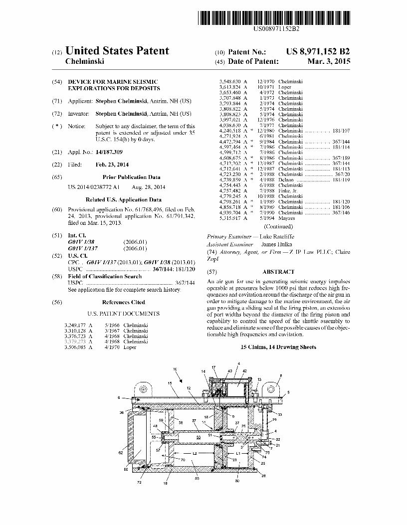
(54) DEVICE FOR MARINE SEISMIC EXPLORATIONS FOR DEPOSITS
(71) Applicant: Stephen Chelminski, Antrim, NH (US)
(72) Inventor: Stephen Chelminski, Antrim, NH (US)
( * ) Notice: Subject to any disclaimer, the term ofthis patent is extended or adjusted under 35 U.S.C. 154(b) by 0 days.
(21) Appl. No.: 14/187,309
(22) Filed: Feb.23,2014
(65) Prior Publication Data
US 2014/0238772 Al Aug. 28, 2014
Related U.S. Application Data
(60) Provisional application No. 61/768,496, filed on Feb. 24, 2013, provisional application No. 61/791,342, filed on Mar. 15, 2013.
(51) Int. Cl. GOlV 1138 GOlV 11137
(2006.01) (2006.01)
(52) U.S. Cl. CPC . GOlV 11137 (2013.01); GOlV 1138 (2013.01) USPC ........................................... 367/144; 181/120
( 58) Field of Classification Search USPC .......................................................... 367/144 See application file for complete search history.
(56) References Cited
U.S. PATENT DOCUMENTS
3,249,177 A 5/1966 Chelminski 3,310,128 A 3/1967 Chelminski 3,376,723 A 4/1968 Chelminski 3,379,273 A 4/1968 Chelminski 3,506,085 A 4/1970 Loper
62
72 18
I lllll llllllll Ill lllll lllll lllll lllll lllll 111111111111111111111111111111111 US008971152B2
(IO) Patent No.: US 8,971,152 B2 Mar.3,2015 (45) Date of Patent:
3,548,630 A 12/1970 Chelminski 3,613,824 A 10/1971 Loper 3,653,460 A 4/1972 Chelminski 3,707,848 A 111973 Chelminski 3,793,844 A 2/1974 Chelminski 3,808,822 A 5/1974 Chelminski 3,808,823 A 5/1974 Chelminski 3,997,021 A 12/1976 Chelminski 4,038,630 A 7/1977 Chelminski 4,240,518 A * 12/1980 Chelminski . 1811107 4,271,924 A 6/1981 Chelminski 4,472,794 A * 9/1984 Chelminski ................... 367/144 4,597,464 A * 7/1986 Chelminski . 1811114 4,599,712 A 7/1986 Chelminski 4,608,675 A * 8/1986 Chelminski ................... 367/189 4,712,202 A * 12/1987 Chelminski ................... 367/144 4,712,641 A * 12/1987 Chelminski . 1811113 4,723,230 A * 2/1988 Chelminski ..................... 367/20 4,739,859 A * 4/1988 Delano 1811119 4,754,443 A 6/1988 Chelminski 4,757,482 A 7/1988 Fiske, Jr. 4,779,245 A 10/1988 Chelminski 4,798,261 A * 111989 Chelminski . 1811120 4,858,718 A * 8/1989 Chelminski . 1811106 4,939,704 A * 7/1990 Chelminski ................... 367/146 5,315,917 A 5/1994 Mayzes
(Continued)
Primary Examiner - Luke Ratcliffe Assistant Examiner - James Hulka (74) Attorney, Agent, or Firm - Z IP Law PLLC; Claire Zapf
(57) ABSTRACT
An air gun for use in generating seismic energy impulses operable at pressures below 1000 psi that reduces high frequencies and cavitation around the discharge of the air gun in order to mitigate damage to the marine environment, the air gun providing a sliding seal at the firing piston, an extension of port widths beyond the diameter of the firing piston and capability to control the speed of the shuttle assembly to reduce and eliminate some of the possible causes of the objectionable high frequencies and cavitation.
15 Claims, 14 Drawing Sheets
4
(56) References Cited
US 8,971,152 B2 Page 2
U.S. PATENT DOCUMENTS
6,612,396 Bl* 7,269,099 B2 8,223,591 B2
5,432,757 A 5,615,170 A * 5,978,316 A * 6,464,035 Bl *
7/1995 Chelminski 3/1997 Chelminski ..................... 367/15
1111999 Ambsetal. ................... 367/134 10/2002 Chelminski . 1811120
2006/0021609 Al* 2008/0019214 Al* 2010/0320027 Al*
* cited by examiner
9/2003 9/2007 7/2012 212006 1/2008
12/2010
Chelminski et al. Jensen Chelminski
1811113
Jensen 124/56 Pramik ........................... 367/16 Chelminski . 1811120
U.S. Patent
l/ r(T(, ', \:;±:'.)
'· ... ·-.................................. ..
Mar.3,2015
..-..-
r--N
©
Sheet 1of14
/ ~I ,l N / _J
/ / 0
I'-
US 8,971,152 B2
0 ("')
0 I..()
..-(9
LL
U.S. Patent
0 ro
Mar.3,2015
<D N
co
Sheet 2of14
N
~ u::
US 8,971,152 B2
..--N
N N
U.S. Patent
"tj" co
N co
Mar.3,2015
N co
co
l I I
I., •• )
r- -, I I
Sheet 3of14
co co
C") ..-
D
co co
US 8,971,152 B2
U.S. Patent Mar.3,2015
I i ... -····"''- ..... ~
Sheet 4of14 US 8,971,152 B2
0 C')
00 (!)
U.S. Patent
co L!')
Mar.3,2015 Sheet 5of14 US 8,971,152 B2
U.S. Patent Mar.3,2015 Sheet 6of14 US 8,971,152 B2
..-00
-}\
Ii (+-, ~
CJ) ! 'l 'IV N I I ..-
!J M .q-
CJ) ,/ '' N
... , ....
..... I'-I'-
co LO L ___ --i <!)
I
LI... I ,-
<( LO
-...:: t9 -<O;
LI...
00 N c.o LO
60
/./'""~~'·'~" ... ," r fi.; 1 ~ .,,_,
15
100
\ 12
102 >.t 111 L2---.
70 /20
179 50 FIG. 6
17 42
122
157
168
\ ·-
196 152
~ 00 • ~ ~ ~ ~ = ~
~ ~ :-:
"'(.H
N 0 .... Ul
1J1
=-('D ('D ..... -....J 0 ..... .... .i;...
d rJl.
_,,OIO \C -....l !"'" "'"" tit N
= N
U.S. Patent
N 0) ....-
Mar.3,2015
C"? 0 N
(!) en ......
Sheet 9of14
N N ......
'<:!'" 0) ......
US 8,971,152 B2
co I'--
<.9 LL
U.S. Patent
N 0 N
N LO ..-
~ 0) LO ......
Mar.3,2015
co LO
r--.. N ......
Sheet 10of14
co N ......
US 8,971,152 B2
~---,--· --...--i__
U.S. Patent Mar.3,2015
(j) LO -----Hr-.-+-'""'-4"
N 0 N
......
. ··· \
\\ ~ \ \ \ \ ~.
Sheet 11of14 US 8,971,152 B2
Tl':h~-:4-- """ '""h'---1-""I (j) ......
U.S. Patent Mar.3,2015 Sheet 12of14
<( 00
US 8,971,152 B2
U.S. Patent
N co
Mar.3,2015
I
t---1
Sheet 13of14
co C'?
co co (.9
LL
US 8,971,152 B2
co ......
U.S. Patent Mar.3,2015 Sheet 14of14 US 8,971,152 B2
0 CX)
CD LL
US 8,971,152 B2 1
DEVICE FOR MARINE SEISMIC EXPLORATIONS FOR DEPOSITS
RELATED PATENT APPLICATIONS
This application claims the benefit of pending U.S. Provisional Patent Application No. 61/768,496 filed Feb. 24, 2013 and U.S. Provisional Patent Application No. 61/791,342 filed Mar. 15, 2013 both applications entitled DEVICE FOR MARINE SEISMIC EXPLORATIONS FOR DEPOSITS which are each hereby incorporated herein by reference in the entirety.
FIELD OF THE INVENTION
The present invention relates to air guns intended for use in generating seismic energy impulses, i.e. acoustical waves, in a body of water. More particularly, this invention relates to low pressure air guns operable at pressures below 1000 psi in order to mitigate damage to the marine environment by reducing or eliminating high frequency sounds which are thought to be the source of damage to the hearing of marine mammals and fish as well as disturbing the habitats and well-being of marine life.
BACKGROUND OF THE INVENTION
Air guns, as used herein, are sound sources for marine seismic exploration for petroleum deposits. The operating components of air guns of the prior art include a firing chamber holding a charge of gas under high pressure, a two-piston shuttle assembly having a firing piston which retains the charge of pressurized gas within the firing chamber, and an operating piston positioned within an operating chamber where highly pressurized gas acts against the operating piston to maintain the shuttle assembly in a closed position until firing. A hollow shaft of the shuttle assembly interconnects the two pistons and provides for pressurized gas to flow from the operating chamber through the shaft to charge the firing chamber. The air gun is triggered using a solenoid operated valve to release high pressure air into the operating chamber actuating the shuttle assembly to cause an abrupt discharge of high pressure air from the firing chamber through discharge ports and directly into the surrounding water, the water in which the air gun is immersed.
Air guns of the prior art are normally run using an air compressor on board an exploration vessel that yields high pressure compressed air in the range of 2000 psi to 3000 psi. The air gun is towed astern. The return signals are received by an array of towed hydrophones. Air guns are relatively deep penetration sources, operating with output frequencies generally between 10 Hz to about 1200 Hz, to identify subsurface geologic layers and define the subsurface structure. The present invention provides many advantages considered significant and valuable by the inventor hereof. The inventor hereof has additional patents such as U.S. Pat. Nos. 3,379,273 4,038,630, 4,271,924, 4,599,712, 4,779,245, 5,432,757, and 8,223,591. There are also some other inventors in the same field such as Fiske, U.S. Pat. No. 4,757,482, Mayzes, U.S. Pat. No. 5,315,917, Jensen U.S. Pat. No. 7,269,099 and others in the field.
OBJECTS AND SUMMARY OF THE INVENTION
As noted, air guns of the prior art that are used for oil exploration typically use air pressures of from 2000 psi to
2 3000 psi which explodes from the air guns when they are triggered thus producing the sound pulses used for seismic analysis. The high operating pressures of these air guns produce spurious high frequency sounds which are not helpful
5 for the purpose of finding oil and which are thought to be the source of damage to the hearing of marine mammals and fish as well as disturbing the habitats and well-being of marine life. There is recently mounting pressure on the exploration industry to eliminate these high frequencies from the pulses
10 of the air gun arrays used. Possible causes of these high frequencies being, 1) the high pressure which air guns are run at cause cavitation at the corners of the ports as the air bursts out of the ports; 2) high pressure air leaking from clearances
15 between the gun housing and shuttle as the shuttle accelerates after being triggered before clearing the ports; 3) conventional air guns shoot a slug of water out of the ports as the shuttle accelerates after the gun is triggered this slug of water may be producing a water gun effect causing cavitation as
20 water guns do when they are triggered; and 4) the high pressure air may rush out of the ports at such high velocity as to cause high frequency sounds due to cavitation around the edges of the ports during its acceleration from the ports. The high pressures as well produce a very short rise time of the
25 initial pulse that is thought to also be a cause of unwanted high frequencies. The air gun of the present invention reduces high frequencies and cavitations by providing a sliding seal at the firing piston, extending the discharge port widths beyond the diameter of the firing piston and controlling the speed of the
30 shuttle assembly to control the rate of release of pressurized air through the outlet ports. By controlling the rate of release of the pressurized air, the rise time from zero pressure to peak pressure of the first or primary pressure pulse may be slowed, increasing the time to reach peak pressure which may in fact
35 reduce some of the causes the objectionable high frequencies and cavitation. Additionally, providing an air gun which fires at low pressure will itself be a source of reduced high frequency noise.
It is an object of the present invention to operate an air gun 40 at low pressures below 1000 psi and more preferably at pres
sures from 400 psi-600 psi. It is another object of the invention to provide an air gun
which produces little or no harmful high frequencies. It is another object of the invention to provide an air gun
45 which produces increased low frequency output. It is another object of the invention to provide an air gun
which reduces cavitation around the air gun to limit the disruption of the marine ecosystem.
It is another object of the invention to provide a sound 50 source which will produce more low frequency energy and
less high frequencies. It is another object of the present invention to assemble an
air gun lighter in construction in proportion to the lower operating pressure of a low pressure air gun as compared to
55 the operating pressure of a conventional high pressure air gun thereby producing a lighter and more easily handled air gun.
It is another object of the present invention to assemble a low pressure air gun using a snap ring to affix the firing chamber to the cylindrical housing of the low pressure air gun
60 housing. It is another object of the present invention to assemble a
low pressure air gun using a snap ring to affix the operating chamber head to the cylindrical housing of the low pressure air gun housing.
65 It is another object of the present invention to reduce the use of bolts or clamp rings in assembling the air gun by using snap rings.
US 8,971,152 B2 3
It is another object of the present invention to assemble a low pressure air gun having shuttle assembly flanges that are thinner and lighter than conventional high pressure air guns providing for faster acceleration of the shuttle assembly within the air gun housing.
It is another object of the present invention to assemble a low pressure air gun having a sliding firing seal that is directly adjacent to the ports to prevent the release of air from the firing chamber until the firing piston moves past the ports.
4 end of the shuttle assembly shaft, the firing piston separating the air cushion chamber from the firing chamber; and wherein the air cushion chamber is of a length along the shuttle axis that is at least 1.2 times the length of the operating chamber along the shuttle axis.
It is another object of the present invention to prevent 10
leakage during the acceleration distance.
The air gun for seismic exploration operates at pressures below 1000 psi and more preferably within a range of 400 psi to 600 psi. The bulkhead wall of the air gun for seismic exploration may be vacuum brazed within the cylindrical housing. The central opening in the bulkhead wall of the air gun may have shaft seal rings and a retainer ring. The shuttle
It is another object of the present invention to extend the width of the ports beyond the outer diameter of the firing piston providing a larger communication area of air expelled to the outside water for the least amount of travel of the shuttle 15
assembly.
assembly shaft has a hollow bore through the shaft and cylindrical bearings and piston rings within the hollow bore and a shuttle assembly support spindle is inserted within the hollow bore. The air gun for seismic exploration further comprises snap rings to attach the firing chamber and an operating
It is another object of the present invention to improve the firing precision of the air gun by providing a shortened trigger air passage, the air passage at a length shorter than the radius of the operating flange.
chamber head to the cylindrical housing. The air gun for seismic exploration further comprises a backbone vacuum brazed permanently in place on top of and to reinforce the
20 cylindrical housing and serve as a flat mounting surface for solenoid operated air gun firing valve. The air gun for seismic exploration further comprises a trigger air passage directly through the backbone and the bulkhead wall to an annular
It is another object of the invention to provide an air cushion chamber of a length that is approximately 20% longer in length than the length of the operating chamber thereby reducing pressure buildup in the air cushion chamber that may decrease the length of the stroke of the shuttle assembly. 25
space of the operating flange within the operating chamber. The air gun may comprise a solenoid valve housing detachable from the reinforcing backbone, the solenoid valve hous-It is another object of the invention to provide full opening
of the ports at low pressure. It is another object of the invention that from a set position
the distance from the inner face of the firing piston is longer than the distance from the face of the operating flange to the 30
chamber head.
ing enclosing one of at least a solenoid operated air gun firing valve and a firing circuit. Alternatively, the air gun may comprise a solenoid valve housing vacuum brazed to the reinforcing backbone. The cup shaped firing piston of the air gun may have a sliding seal preventing air leaks between the cylindri-
It is another object of the invention to assemble an air gun having a piston ring on the outside diameter of the shuttle assembly operating flange.
It is another object of the invention to control the speed of the shuttle assembly through adjustment of the geometry of grooves by adjusting the depth, width, length, and slope of grooves within a fluted sleeve within the operating chamber.
It is another object of the present invention to provide an air gun with improved shuttle assembly speed control.
It is another object of the present invention to control the rise time from zero pressure to peak pressure of the first or primary pressure pulse to increase the time to reach peak pressure to reduce or eliminate objectionable high frequencies.
It is another object of the present invention to assemble a low pressure air gun using vacuum oven brazing at mating surfaces to affix a reinforcing backbone to the cylindrical housing, the back bone having air passages for providing compressed air to the low pressure air gun.
It is another object of the present invention to assemble a low pressure air gun using vacuum oven brazing to affix a bulkhead wall within the cylindrical housing of the air gun.
It is another object of the present invention to reduce degradation and wear on seals and structural components of the low pressure air gun.
It is a still further object of the invention to provide an air gun which by virtue of being operated at low pressures is safer.
The present invention is related to an air gun for seismic exploration, that comprises a cylindrical housing having a plurality of discharge ports; a bulkhead wall within the cylindrical housing to separate an operating chamber from an air cushion chamber; a shuttle assembly having a shaft inserted through a central opening in the bulkhead wall and having an operating flange on an end of the shaft within the operating chamber; a cup shaped firing piston secured to an opposing
cal housing, firing chamber and air cushion chamber until the air gun is triggered and air is released through the plurality of discharge ports. The plurality of discharge ports of the air gun
35 may have at least one horizontal post divider and the ports may extend beyond the outer diameter of the cup shaped firing piston, and the ports may point outwardly opposite each other and horizontally away from the center line of the air gun.
40 The present invention further relates to a low pressure air gun for seismic exploration which reduces spurious high frequency sounds, that comprises a cylindrical housing; a bulkhead wall within the cylindrical housing to separate an operating chamber from an air cushion chamber; a central
45 opening in the bulkhead wall; a shuttle assembly having a shaft inserted through the central opening in the bulkhead wall and having an operating flange on an end of the shaft within the operating chamber; a cup shaped firing piston secured to an opposing end of the shuttle assembly shaft
50 separating the air cushion chamber from the firing chamber; a plurality of ports formed within the cylindrical housing, the width of the ports extending to a distance greater than the outer diameter of the cup shaped firing piston; a firing chamber secured to the cylindrical housing; and the air gun oper-
55 ates at pressures is in a range of 400 psi to 1000 psi. The air cushion chamber of the low pressure air gun for
seismic exploration which reduces spurious high frequency sounds may be of a length along the shuttle axis that is at least 1.2 times the length within the operating chamber along the
60 shuttle axis as measured from the face of the operating flange to an operating chamber head. The low pressure air gun for seismic exploration which reduces spurious high frequency sounds may further comprise a speed controller which comprises a fluted sleeve installed within the operating chamber;
65 a piston ring installed to the outer diameter of the operating flange; and when triggered the operating flange moves the piston ring over the fluted sleeve to control the speed of the
US 8,971,152 B2 5
shuttle assembly. The speed controller controls the speed of the shuttle assembly to control the rise time from zero pressure to peak pressure of the primary pressure pulse. The speed controller fluted sleeve has grooves and the slope of the rise time of the primary pressure pulse is adjusted by modifying the geometry of one of at least the length, width, depth, slope and shape of the grooves. The low pressure air gun may further comprise a fluid filled speed controller.
The low pressure air gun for seismic exploration which reduces spurious high frequency sounds further comprises 10
snap rings to attach the firing chamber and the operating chamber head to the cylindrical housing. The low pressure air gun for seismic exploration which reduces spurious high frequency sounds further comprises a backbone vacuum brazed permanently in place on top of and to reinforce the 15
cylindrical housing and serve as a flat mounting surface for solenoid operated air gun firing valve. The low pressure air gun further comprises a trigger air passage directly through the backbone and the bulkhead wall to an annular space of the operating flange within the operating chamber said trigger air 20
passage length less than radius of the operating flange. The low pressure air gun may further comprise a solenoid valve housing detachable from the reinforcing backbone, the solenoid valve housing enclosing one of at least a solenoid operated air gun firing valve and a firing circuit. Alternatively, the 25
low pressure air gun may further comprise a solenoid valve housing vacuum brazed to the reinforcing backbone. The bulkhead wall of the low pressure air gun may be brazed in place to the cylindrical housing. The low pressure air gun may further comprise shaft seal rings and a retainer ring installed 30
within the central opening in the bulkhead wall around the shuttle assembly shaft to seal the operating chamber from the air cushion chamber. The cup shaped firing piston of the low pressure air gun may have a sliding seal preventing air leaks between the cylindrical housing, firing chamber and air cush- 35
ion chamber until the air gun is triggered and air is released through the plurality of ports. The plurality of ports of the low pressure air gun may have at least one horizontal post divider and the ports may extend beyond the outer diameterof the cup shaped firing piston, said ports pointing outwardly opposite 40
each other and horizontally away from the center line of the air gun.
The present invention is further related to a method of reducing spurious high frequency sounds from an air gun, comprising the steps of assembling an air gun having a cylin- 45
drical housing; vacuum brazing a bulkhead wall within the cylindrical housing to separate an operating chamber from an air cushion chamber; installing close fitting shaft seal rings and a retainer ring within a central opening in the bulkhead wall; inserting a shuttle assembly having a shaft through the 50
central opening in the bulkhead wall to seal the operating chamber from the air cushion chamber, the shuttle assembly shaft having a hollow bore through the shaft and having an operating flange on an end of the shaft within the operating chamber; inserting a fluted sleeve within the operating cham- 55
ber; installing a piston ring to the outer diameter of the operating flange; installing cylindrical bearings and shaft seal rings within the hollow bore of the shuttle assembly shaft; inserting a shuttle assembly support spindle within the hollow bore; affixing an operating chamber head to the cylindrical 60
housing snap rings; affixing a cup shaped firing piston to an opposing end of the shuttle assembly shaft within the air cushion chamber; forming a plurality of ports within the cylindrical housing, the width of the ports extending to a distance greater than the outer diameter of the cup shaped 65
firing piston; affixing a firing chamber to the cylindrical housing snap rings; supplying an air trigger pulse to the operating
6 flange to move the piston ring over the fluted sleeve to control the speed of the operating flange and thereby the rise time from zero pressure to peak pressure of the primary pressure pulse as airis expelling from the ports as the bottom end of the cup shaped firing piston crosses an edge of the plurality of ports. The method of reducing spurious high frequency sounds from an air gun may further comprise the steps of vacuum brazing a reinforcing backbone to the cylindrical housing; and vacuum brazing a solenoid valve housing to the reinforcing backbone, the solenoid valve housing enclosing a solenoid operated air gun firing valve and firing circuit. The method of reducing spurious high frequency sounds from an air gun may further comprise the step of sealing the bottom end of the cup shaped firing piston to the firing chamber using a spring loaded backup ring and sliding firing seal. The method of reducing spurious high frequency sounds from an air gun may further comprise the step of operating the air gun at pressures below 1000 psi and more preferably within a range of 400 psi to 600 psi.
These and other features, advantages and improvements according to this invention will be better understood by reference to the following detailed description and accompanying drawings. While references may be made to upper, lower, vertical and horizontal, these terms are used merely to describe the relationship of components and not to limit the operation of the present invention to any one orientation.
BRIEF DESCRIPTION OF THE DRAWINGS
The invention, together with further objects, features, aspects and advantages thereof will be more fully understood and appreciated by consideration of the following description in conjunction with the accompanying drawings in which the respective elements bear the same reference numerals throughout the various views.
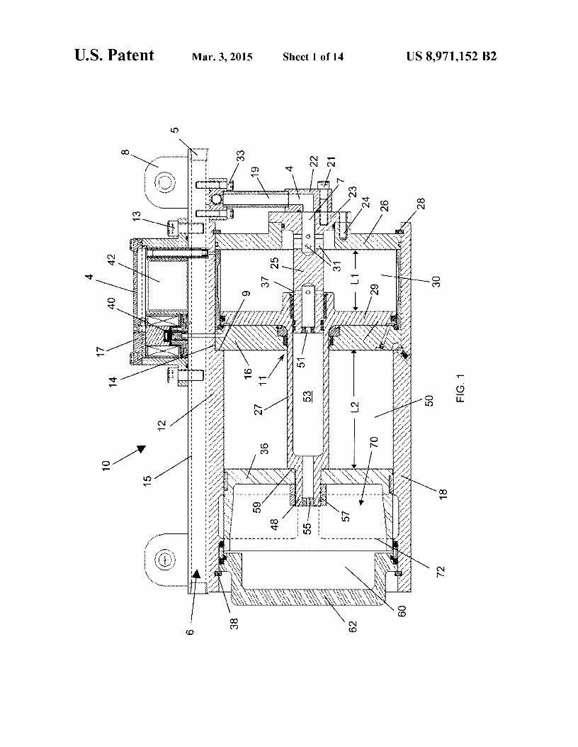
FIG. 1 is a longitudinal cross sectional view of an embodiment of the air gun of the present invention;
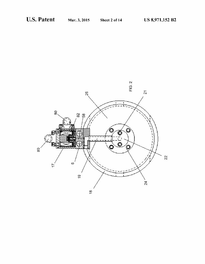
FIG. 2 is an end view of an embodiment of the air gun of the present invention showing an electrical cable block connector that may be optionally on the top or side of the solenoid valve housing of the present invention;
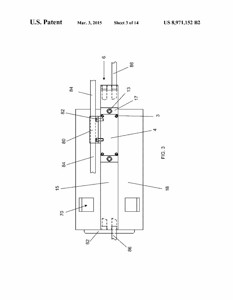
FIG. 3 is a top view of an embodiment of the air gun of the present invention;
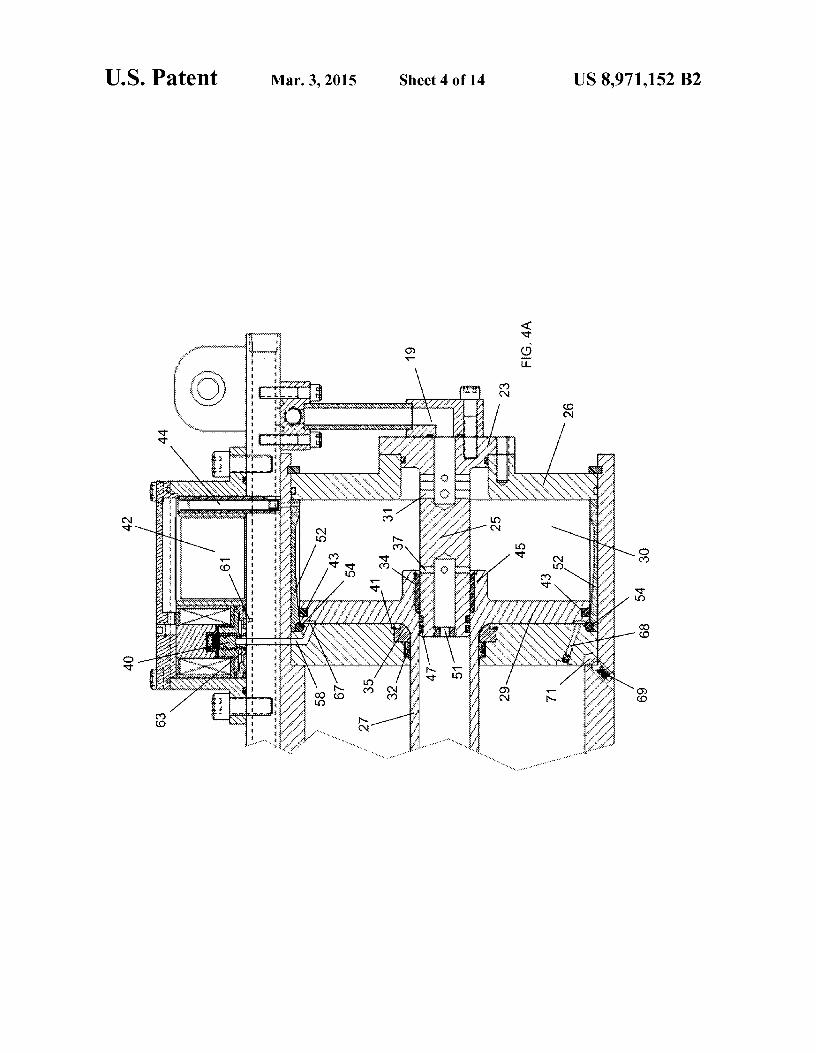
FIG. 4A is a longitudinal cross sectional view of an embodiment of the solenoid valve housing and operating chamber of the air gun of the present invention;
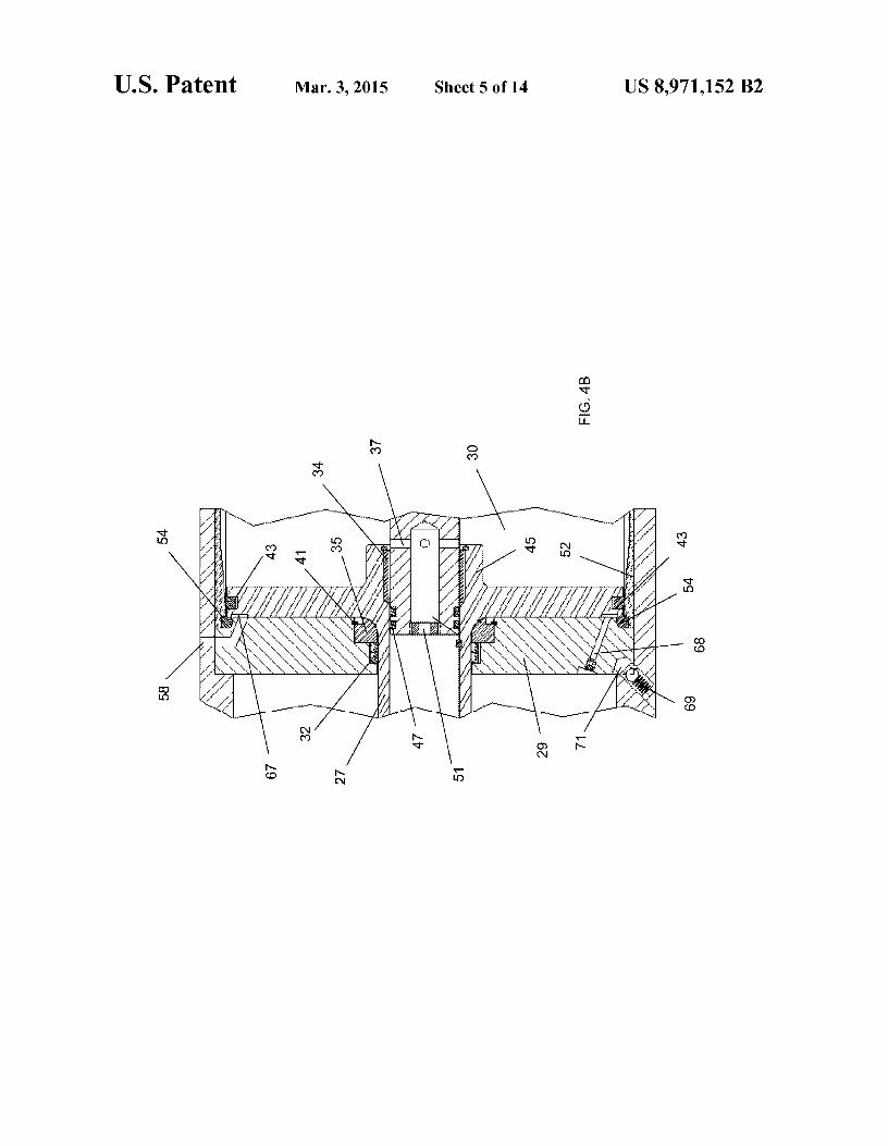
FIG. 4B is a longitudinal cross sectional view of an embodiment of the operating chamber of the air gun of the present invention;
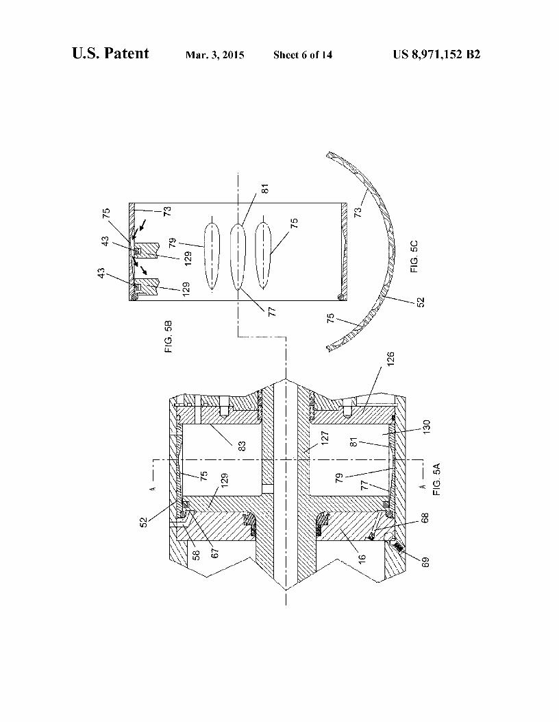
FIG. SA is a longitudinal cross sectional view of an embodiment of the liner sleeve of the operating chamber of the air gun of the present invention;
FIG. SB is a longitudinal cross sectional view of an embodiment of the liner sleeve of the operating chamber of the air gun of the present invention;
FIG. SC is a cross sectional view along section A-A ofFIG. SA of an embodiment of the liner sleeve of the operating chamber of the air gun of the present invention;
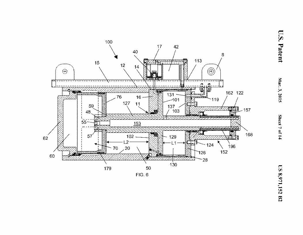
FIG. 6 is a longitudinal cross sectional view of a further embodiment of the air gun of the present invention;
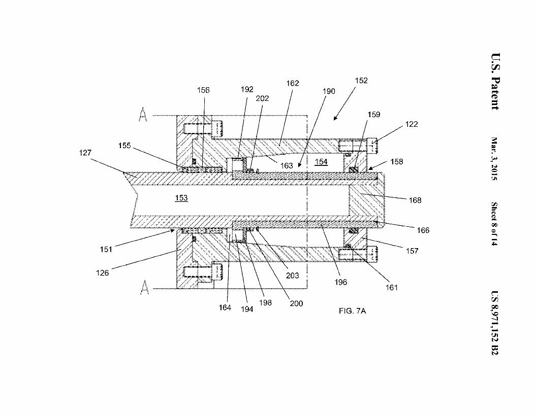
FIG. 7A is a longitudinal cross sectional view of an embodiment of a fluid filled speed controller in the further embodiment of the air gun of the present invention;
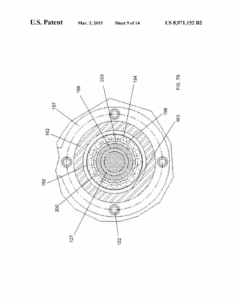
FIG. 7B is a cross sectional view along section A-A ofFIG. 7 A of an embodiment of a fluid filled speed controller in the further embodiment of the air gun of the present invention;
US 8,971,152 B2 7
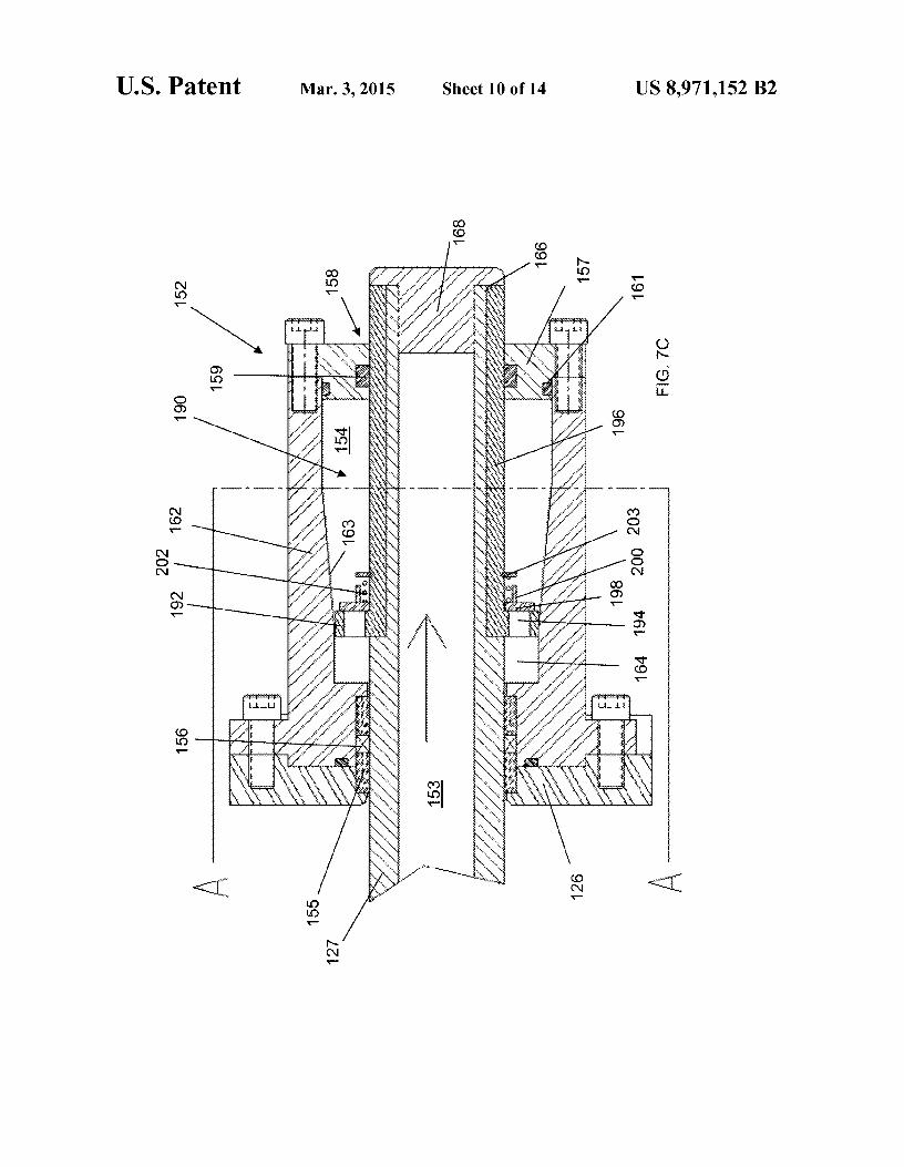
FIG. 7C is a longitudinal cross sectional view of an embodiment of a fluid filled speed controller in the firing position in the further embodiment of the air gun of the present invention;
8 as an air supply passage for the air volume 60 within the firing chamber 62. An air inlet orifice 51 controls the flow rate of air entering the shaft interior bore 53 and an outlet orifice 55
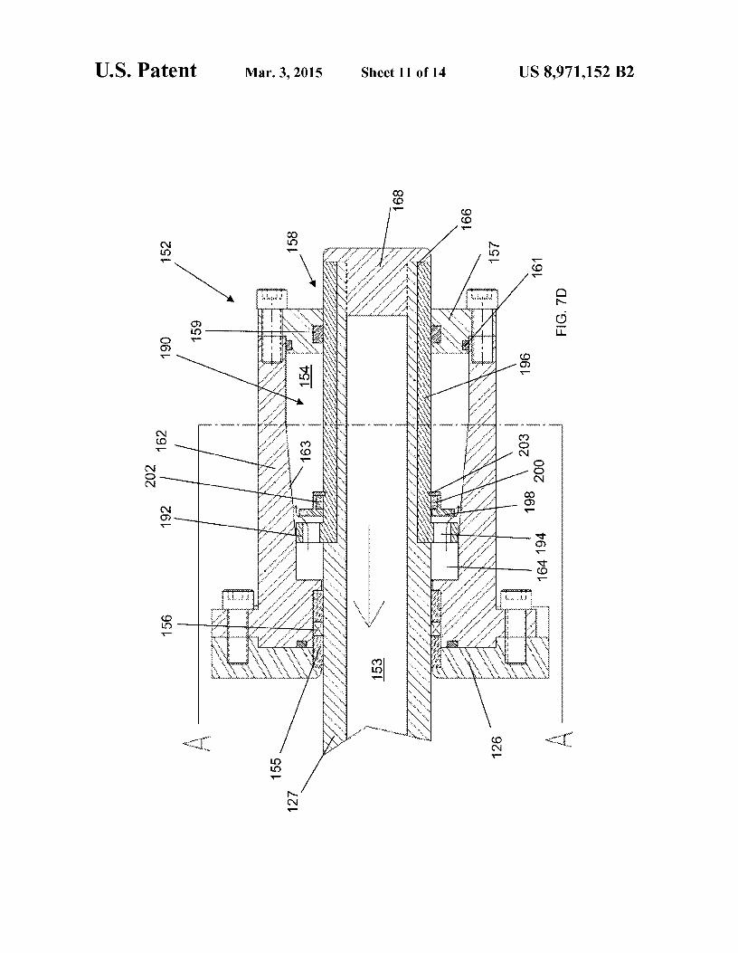
FIG. 7D is a longitudinal cross sectional view of an 5
embodiment of a fluid filled speed controller in the set position in the further embodiment of the air gun of the present invention;
controls the rate of flow of air entering the volume 60 of the firing chamber 62. Air is supplied from the operating chamber 30 through inlet holes 37 in the shuttle assembly support spindle 25. The shaft end 4S of the shuttle assembly shaft 27 is threaded and the cup shaped firing piston 36 is attached to the shaft end 4S using a nut 57 to lock the cup flange 36 FIG. SA is a longitudinal cross sectional view of an
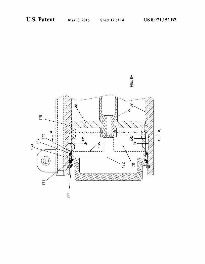
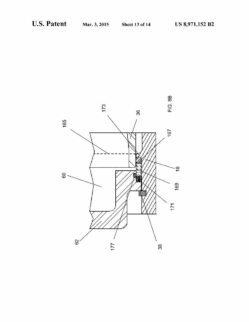
embodiment of the firing chamber and discharge ports of the air gun of the present invention;
FIG. SB is a cut out cross sectional view of an embodiment of the sliding firing seal and assembly of the air gun of the present invention; and
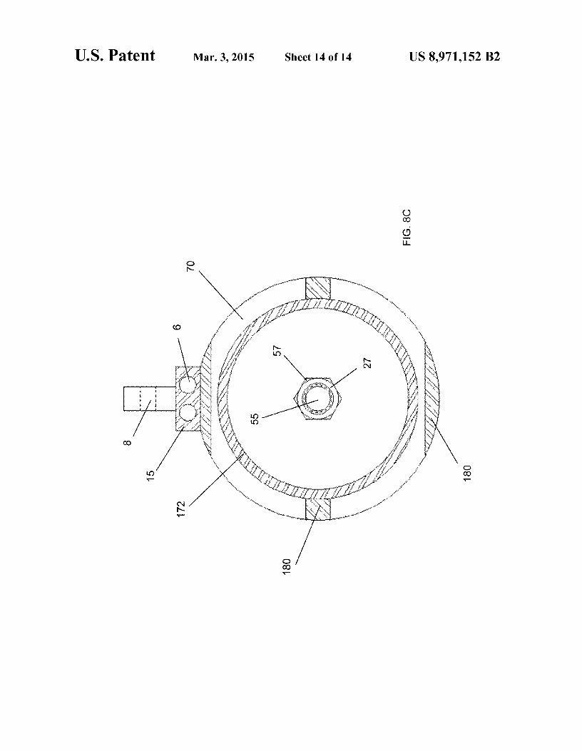
FIG. SC is a cross sectional view along section A-A of FIG. SA of an embodiment of the firing chamber and discharge ports of the air gun of the present invention.
DETAILED DESCRIPTION OF THE DRAWINGS
10 against a shoulder 59 formed at the base of the shaft 27. Rider bearings 179 installed along the outer diameter of the cup shaped firing piston 36 to provide for the piston to freely slide along the inner walls 20 of the low pressure air gun cylindrical housing lS. In high pressure air guns of the prior art, the space
15 behind the firing piston is filled with water that is displaced as the gun fires may cause cavitation that could disrupt the marine ecosystem. By trapping ambient air behind the firing piston, the displacement of water is reduced limiting a source of cavitation around the water gun. A series of ports 70 are
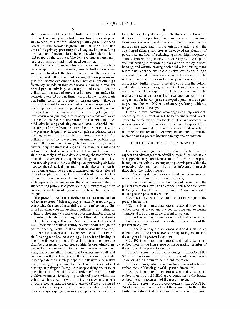
20 formed through the housing lS at the firing chamber 62 as In an embodiment of the present invention, an air gun 10, as indicated by dotted lines 72 showing the openings. The firing
shown in FIG. 1, comprises a dual purpose reinforcing back- chamber 62 may be of any required dimension and may be bone air passage manifold 15 to strengthen the housing lS to replaced to adjust the size to create a larger or smaller volume supply and distribute compressed air through one or more based on survey requirements. The firing chamber 62 is passages 6 by connecting a supply line to a connector 5 on 25 secured to the air gun housing lS using retainer ring 3S. By either end of the backbone 15. The backbone 15 may have one using snap type retainer rings instead of bolts, the cylindrical or more tow ears S that may be brazed into the backbone 15 walls of the housing lS may be thinner where there is no for towing the air gun 10. The backbone 15 is secured to the necessity to thicken the wall to install bolts or clamping rings. air gun housing lS by vacuum oven brazing at mating sur- A solenoid valve housing 17 may be bolted using bolts 13 faces 12 between the bottom of the backbone and the air gun 30 or be brazed to the backbone 15. The solenoid valve housing cylindrical housing providing a flattened top for mounting a 17 may enclose only a solenoid valve 40 or a solenoid valve solenoid operated air gun firing valve eliminating the neces- and control circuit 42 based on the specification requirements sity of using bolts to attach the backbone manifold 15 to the of the air gun system. An electrical cable block connector SO housing lS, thus making the air gun more reliable and lighter. extends either from the top or side of the solenoid valve Bulkhead wall 16 is also brazed into air gun housing lS at 35 housing 17, as shown in FIG. 2. A multi-pin cable connector joint 14 instead of the housing being machined out of a single (not shown) provides for the cable block connector SO to be billet of stainless steel thus saving material costs, machine electrically connected to the solenoid valve 40 or control time, and labor. The bulkhead wall 16 may be seated against circuit 42 components. The block connector SO may then be a shoulder 9 formed in the housing lS where the diameter of bolted to the solenoid valve housing 17 using bolts S2. The the housing lS is enlarged to secure the bulkhead wall 16 and 40 cable block connector SO may be detached to replace the form the tubular structure of the operating chamber 30. entire solenoid valve housing 17 with the solenoid valve 40 Because the air gun 10 is run at low pressures the housing lS and control circuit 42 as a unit. Alternatively, an access cover may have a dimensioned wall thickness that is thinner than 4 attached to the solenoid valve housing 17 using bolts 3 may high pressure air guns of the prior art, reducing the overall be provided to provide access to repair or replace the solenoid weight and costs of the air gun 10. The shuttle assembly 45 valvehousing17internalcomponents.Inthismanneradefec-includes a shuttle assembly shaft 27 and an operating flange tive control circuit or solenoid valve can be repaired or 29. The shuttle assembly shaft 27 is inserted through the replaced without removal of the solenoid valve housing from opening to the operating chamber 30 and through a center the backbone 15. The cable block connector SO further pro-hole 11 in the bulkhead wall 16 with the sealing face of the vides for a faulty air gun 10 to be replaced by only discon-operating flange 29 aligning against the bulkhead wall 16. 50 necting the electrical cable block connector SO from the sole-Instead of using bolts or clamping rings, the operating cham- noid valve housing and the air supply line from the backbone ber 30 is enclosed by securing in place the operating chamber 15 and attaching the cable block connector SO and air supply head 26 using a retaining ring 2S. The shuttle assembly sup- line to a new air gun 10, greatly reducing down time for port spindle 25 is inserted into the hollow shuttle assembly failures during deployment of an array of air guns. As shown shaft with and the shuttle assembly support spindle flange 23 55 the trigger air passage 5S extends between the air passages 6 is secured to the operating chamber head 26 using bolt circle directly through the backbone 15 to provide for more precise 24. An air channel block 22 is secured to the shuttle assembly firing of the air gun 10 where the air trigger passage is of a support spindle flange 23 using bolt circle 21. The air channel substantially shortened length as compared to air guns of the block 22 has a 90° passage 4 to direct air flow through the air prior art. input fitting 19 and through the spindle air passage 7 to inlet 60 A top view of the air gun 10 is shown in FIG. 3 with the openings 31 to provide air to the operating chamber 30. The electric cable block connector SO directedoffto the side of the compressed air input fitting 19 is secured to the backbone 15 solenoid valve housing 17 and electrical cables S4 extending using air input line retainer bolts 33 to communicate with from the block connector SO to the exploration vessel or other compressed air passage 6. similar air guns. Air supply lines S6 extend from each end of
The shuttle assembly shaft 27 extends through the bulk- 65 the backbone 15. A second air passage 6 may be provided for head wall 16 to the air cushion chamber 50. The shaft 27 may additional air supply lines if a number of air guns 10 are used behollowtoreducetheoverall weightoftheairgunlO and act in a single array. The trigger air passage 5S directs air flow to
US 8,971,152 B2 9
a grooved annular space 67 around the inner face of the operating flange 29 as shown in FIG. 4A.
10 middle area 79 and tapers to a less deep rounded channel 81 closer to the inner wall 83 of the operating chamber head 26.
The present invention does not require holes to be drilled through the bulkhead wall 16 to allow water to flow to lubricate the shaft seals because the shuttle assembly shaft 27 is 5
sealed using two close fitting self-lubricating shaft seal rings 32, as shown in FIG. 4B, that seal the operating chamber 30 from the air cushion chamber SO and allow the shuttle shaft 27
When the operating flange 129 is in the set to fire position shown in FIG. SA, there is none or very little air leakage around the piston ring 43. When the trigger valve 6S is actuated by an electric pulse from the firing circuit 42, the flange 129 accelerates from left to right. A time break transducer 44 installed at a passage from the operating chamber 130 trans-
to move freely through the center hole 11 of the bulkhead wall 16 without leakage. A retainer ring 3S holds the shaft seal 10
rings 32 in place with the retainer ring 3S being held in place using a snap ring 41. A sliding sleeve bearing 34 is installed within a recess 4S where the shuttle assembly shaft 27 is installed along the shuttle assembly support spindle 2S with two piston rings 47 sealing the shaft 27 from the operating 15
chamber 30. A piston ring 43 surrounds the operating flange
mits a signal to the control circuit 42 that the air gun 10 has fired. As shown in FIG. SB, arrows indicate air flow as the piston ring 43 of the flange 129 rides along the lands 73 of the inner surface of the liner sleeve S2 between the grooves 7S. The lands 73 guide the piston ring 43 within the operating flange 129. By restricting air flow initially through the formation of the shallow narrow shape of the groove 7S at the first end 77, the rise time of the first primary pressure pulse may be slowed until the operating flange 129 reaches the widened channel in the middle 79 of the groove 7S. The
29 to travel along a liner sleeve S2 which retains the operating seal S4.
A trigger valve air supply hole 61 is drilled through the top wall of air passage 6 into the trigger valve air input chamber 63, enabling solenoid operated trigger valve 6S to be supplied with air. When the trigger valve 6S is actuated by an electric pulse from the firing circuit 42, a shot of air flows rapidly through trigger air passage S8 into annular space 67 to trigger the air gun by breaking the seal between the outside diameter of operating flange 29 and operating seal S4 allowing the shuttle assembly to start its firing movement as pushed by the air pressure within the firing chamber 62 across the cross sectional area of the cup shaped firing piston 30. Air vent passage 68 is drilled through bulkhead wall 16 near the bottom of operating chamber S8 and air cushion chamber SO, thus allowing the air pressure in the annular space 67 to be at ambient water pressure when the operating flange 29 has returned to the set position. Check valve 69 positioned for outward flow, vents water or air from ambient air cushion chamber SO through drilled port 71. If any water seeps into the ambient air cushion chamber SO between air gun shots, the air is purged out through check valve 69 by the temporary air pressure build up in ambient air cushion chamber SO during the time the cup shaped firing piston 3 6 is moving from the set position as shown in FIGS. 1, 4A and 4B, to the right and back again, compressing the air from about ambient water pressure and allowing some of the air to flow through drilled passage 68 into ambient air cushion chamber SO thus pressurizing the chamber SO and pushing any water which may have collected in the bottom of the air cushion chamber SO out through check valve 69 and between the clearance of the cup shaped firing piston rider bearing 179 and the cylindrical wall 20 of the housing 18. Recessed within the bulkhead wall 16, close fitting shaft seal rings 32 and retainer ring 3S prevent air from the operating chamber 30 from leaking through the center hole 11 of the bulkhead wall 16 and the outside diameter of shuttle assembly shaft 27 when the operating flange 29 is not in the set or cocked position.
When the air gun 10 is triggered, the liner sleeve S2 within the operating chamber 30, as shown in FIG. SA, controls the air flow around the operating flange 29 to control the speed of the operating flange 29 as described in patent, U.S. Pat. No. 4,779,245 to the same inventor. However, different from the described conical tapered surface of revolution that would extend completely along the inner surface 73 of the liner sleeve S2, the present invention includes a series of noncontiguous flutes or grooves 7S shown in FIGS. SB and SC as cross sections of the operating chamber 30 along section A-A shown in FIG. SA. The grooves 7S are machined into the sleeve S2 and are formed as a shallow narrow groove at a first end 77, that expands to a deeper rounded channel along a
20 operating flange 129 then progressively accelerates until passing the widened and deepened middle section when flange 129 nears the end 81 where the slope and width of the grooves start to close off the air flow, the flange 129 is slowed by compressing the air within the operating chamber 130 to
25 slow and stop the flange 129 prior to hitting the inner wall 83 of the operating chamber head 126. This is the point where the pressure peaks triggering the time break transducer which puts out the signal that the gun has fired. The speed of the operating flange 129 may therefore be controlled by the
30 geometry of the grooves where the shape, width, length, slope and depth of the groove will all contribute to control of the rise time of the primary pressure pulse. By slowing the rise time, the time for the primary pressure pulse to reach peak pressure is increased which may reduce some high frequencies that are
35 detrimental to marine life. Therefore, the appropriate groove geometry at the lower operating pressures of the air gun 10 may remove a source of spurious frequencies that may cause damage to the hearing of marine manimals and fish.
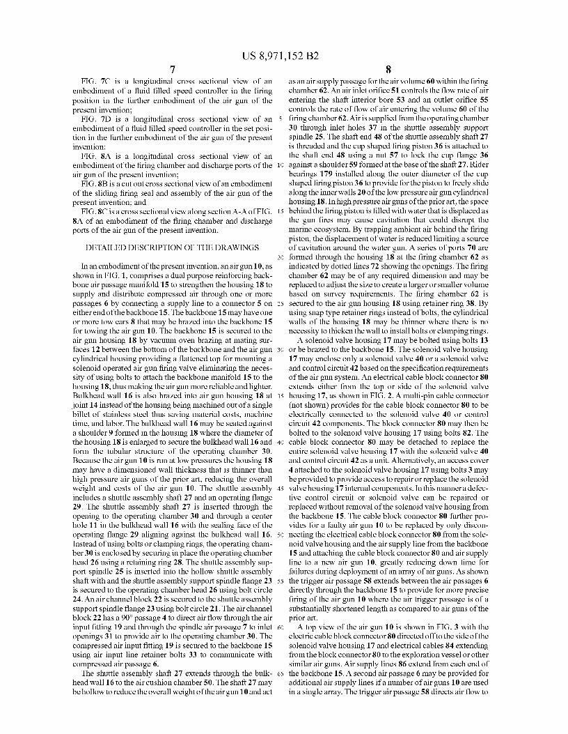
In a further embodiment of the low pressure air gun 100, as 40 shown in FIG. 6, the solenoid valve housing 17 may be affixed
to the backbone lS by vacuum oven brazing at mating surfaces 113 between the bottom of the housing 17 and backbone lS thereby eliminating the necessity of using bolts to attach the solenoid valve housing 17. The operating chamber 130 is
45 supplied with compressed air directly from the air supply line 119 through inlet 131 and the hollow interior bore 1S3 of the shaft 127 is supplied with air through inlet holes 137. The shuttle assembly shaft 127 extends through an opening in the operating chamber head 126. The air cushion chamber SO
50 may be of a length L2 that is at least 1.2 times longer in length along the axis of the shuttle assembly as measured in a set position from the inner face 76 of the firing piston 36 to the inner surface 102 of the bulkhead wall 16 than the length L1 within the operating chamber 30 along the axis of the shuttle
55 assembly as measured in a set position from the inner face 101 of the operating flange 129 to the inner surface 103 of the operating chamber head 126. By increasing the length of the distance from the inner face 76 of the cup shaped firing piston 36 to the bulkhead wall 16, there is less buildup of air pressure
60 within the air cushion chamber SO when firing the air gun and therefore the speed and travel distance of the cup shaped firing piston 36 is less impeded. This provides for the discharge ports 70 to be opened more fully where the shuttle assembly is mostly slowed and stopped by the air cushion
65 build up within the operating chamber 30. By opening the ports 70 more fully, the energy output from operating the air gun 10 at lower pressures may be comparable to high pressure
US 8,971,152 B2 11
air guns of the prior art. A fluid filled speed controller 152 is affixed to the operating chamber head 126 using bolts 124.
12
In this further embodiment which may be in addition to the operating chamber speed controller 52, a hydraulic speed controller 152 may be installed to an extended portion of the 5
shuttle assembly shaft 127 of the air gun 100. The hydraulic speed controller 152 is bolted using bolts 122 to the outside center of the firing chamber head 126 of the air gun 100 to control the speed the shuttle assembly travels after the air gun 100 is triggered. The hydraulic speed controller 152 as shown 10
in FIG. 7A includes an oil filled chamber 154 with the shaft
air gun may be adjusted to control the frequency content of the outgoing pulse in order to eliminate undesired high frequencies from the pulse.
As shown in FIG. SA, due to the very rapid acceleration of the shuttle assembly of high pressure air guns, a very sharp sound output spike occurs when the end surface 172 of the opening cup shaped firing piston 36 clears the opening edge 165 of the exhaust ports 70. The rapid rise time of the resulting sound spike is so sharp, it may produce an abundance of high frequency sound in the surrounding water which is thought to be damaging to marine life such as fish and marine mammals. In order to reduce these spurious high frequencies in a low pressure air gun, a sliding firing seal 167 is installed on the outer diameter of the cup shaped shuttle assembly
assembly 127 of uniform diameter entering the opening 151 of the chamber 154 through two plastic bearings 155 with a shaft seal 156 retained between the two bearings 155. A check valve piston assembly 190 is installed to the shaft 127 and a speed controller housing head 157 is bolted to the top of the oil filled chamber 154 with an opening 15S for the end of the shaft 127 to extend through the head 157. An internal shaft seal 159 seals the outside diameter of the shaft 127 within the speed controller head 157 and an 0-ring seal 161 seals the head 157 to the housing 162. A threaded retainer cap 16S is inserted into the hollow bore 153 to seal the shaft 127 and retain the check valve piston assembly 190 that surrounds the shuttle assembly shaft 127. The check valve piston assembly 190 includes a piston 192 with a ring of holes 194. The piston 192 is held in place within a bore 164 of the housing 162 by a tubular retainer 196 running through the speed controller housing head 157 and shaft seal 159. There is check valve plate 19S shaped like a circular washer biased against the check valve piston 192 by a spring 202 to cover the piston holes 194 causing the piston 192 with holes 194 and the spring biased ring plate 19S to become a check valve to remain closed when the shuttle assembly shaft 127 is accelerating upon triggering of the air gun 100. A spring retainer 200 retains the spring 202 and a ring plate 203 stops the spring biased ring plate 19S and sets the distance that the spring biased ring plate 19S moves when the check valve is opened.
15 flange 36 to prevent the leakage of air prior to the end surface 172 of the cup 36 clearingthe edge 165 of the port. The sliding firing seal 167, as shown in FIG. SB is held securely between the contoured spring loaded back ring 169 and contoured shoulder 173 of the housing lS. A spring 171 is positioned
20 within the spring loaded back ring 169 to provide the force to hold the firing seal 169 against the shoulder 173. In the set position the sliding firing seal 167 seals the outside diameter of the cup shaped firing piston 36 to retain the air within the firing chamber 62. A seal 177 seals the inside diameter of the
25 spring loaded backup ring 169. The firing piston 36 rider bearing 179 is installed around the outer diameterof the upper portion of the cup shaped firing piston 36.
In an embodiment of the present invention, the width of the ports W extends beyond the outer diameter OD of the cup
30 shaped firing piston 36 providing for as much air as possible to be expelled from the firing chamber with the shortest distance travel of the shuttle assembly shaft 27 improving the overall efficiency of the low pressure air sun 10. The ports 70 are formed as divider ports with strengthening horizontal
35 posts lSO to give the air gun housing lS rigidity between each of four ports shown in FIG. SC in cross section of section A-A shown in FIG. SA.
A cross sectional view of the speed controller 152 along 40
section A-A of FIG. 7A is shown in FIG. 7B.
In operation at pressures lower than 1000 psi, the shuttle assembly shaft 27 accelerates when the air gun 10 is triggered and the bottom outside diameter surface 163 of the cup shaped firing piston 36 moves until it passes the sealing
When the air gun shuttle assembly shaft 127 is in the set position before triggering the check valve piston assembly 190 is at the bottom of the speed controller housing 162 as shown in FIG. 7A where the clearance between the piston 192 and housing 162 is small. After triggering the shuttle assembly shaft 127 moves a short distance building pressure up in the housing 162 which acts against the top of the piston 192 and check valve plate 19S closing the holes 194 to retard and control the speed of the shuttle assembly as shown in FIG. 7C. The piston 192 starts to move with the shaft 127 over the outwardly tapered slope 163 of the housing bore 164 and as the shuttle assembly moves a greater distance the diameter around the piston 192 increases which allows the shuttle assembly to move faster until a terminal velocity is reached by the designed clearance between the piston 192 and housing 162. Thus the speed of the shuttle assembly can be controlled by the length of the bore and contour of the slope of the speed controller housing 162. After the shuttle assembly halts its movement after firing it reverses itself to return to the set position and during the return stroke the check valve plate 192
surface of the sliding firing seal 167. The spring loaded backup ring 169 maintains a force on the sliding firing seal 167 to prevent any leakage from around the outer diameter of
45 the cup shaped firing piston 36. Therefore, while moving toward the edge of the ports 165 within the air gun housing lS no compressed air is released from the compression chamber 30 during the acceleration distance. The reduction of air leakage and lower velocity of air as it accelerates out of the ports
50 70 at lower pressures reduces the content of high frequencies in the outgoing pulse and differently from conventional high pressure air guns, may reduce cavitations in the water that may disrupt the marine ecostructure and with the objectionable high frequencies may damage the hearing of marine
55 mammals. Although specific embodiments of the invention have been
disclosed herein in detail, it is to be understood that this is for purposes of illustration. This disclosure is not to be construed as limiting the scope of the invention, since the described
60 embodiments may be changed in details as will become apparent to those skilled in the art in order to adapt the low pressure air guns to particular applications, without departing from the scope of the following claims and equivalents of the claimed elements.
of the hydraulic piston assembly 190 opens to allow free hydraulic fluid such as oil to flow so that the shuttle assembly can return freely to its set position. By controlling the speed of the shuttle assembly shaft 127 through the geometry of the 65
hydraulic speed controller bore 164 and slope 163 of the housing 162 the rate of rise of the outgoing sound pulse of the
What is claimed is: 1. A low pressure air gun for seismic exploration which
reduces high frequency sounds, comprising:
US 8,971,152 B2 13
a cylindrical housing; a bulkhead wall within the cylindrical housing to separate
an operating chamber from an air cushion chamber a central opening in the bulkhead wall; ' a shuttle assembly having a shaft inserted through the
c~ntral opening in the bulkhead wall and having an operatmg flange on an end of the shaft within the operating chamber;
14 7. The low pressure air gun for seismic exploration which
reduces high frequency sounds of claim 1 further comprising a fluid filled speed controller.
8. The low pressure air gun for seismic exploration which reduces high frequency sounds of claim 1 further comprising a backbone vacuum brazed permanently in place on top of and to reinforce the cylindrical housing and serve as a flat mounting surface for solenoid operated air gun firing valve.
9. The low pressure air gun for seismic exploration which a cup shaped firing piston secured to an opposing end of the shuttle assembly shaft separating the air cushion chamber from the firing chamber;
a plural~ty of ports formed within the cylindrical housing, the width of the ports extending to a distance greater than t~e outer diameter of the cup shaped firing piston;
10 reduces high frequency sounds of claim 8 further comprising a trigger air passage directly through the backbone and the b~l~ead wall to. an annular space of the operating flange within the operatmg chamber said trigger air passage length less than the radius of the operating flange.
a finng chamber secured to the cylindrical housing; and wherein the air gun operates at pressures in a range of 400
psi to 1000 psi.
15
2. The low pressure air gun for seismic exploration which reduces high frequency sounds of claim 1, wherein the air cushion chamber in a set position is of a length along the 20
shuttle axis that is at least 1.2 times the length within the operating chamber along the shuttle axis as measured from the face of the operating flange to an operating chamber head.
3. The low pressure air gun for seismic exploration which reduce.s high frequency sounds of claim 2 further comprising 25
snap nngs to attach the firing chamber and the operating chamber head to the cylindrical housing.
10. The low pressure air gun for seismic exploration which reduces high frequency sounds of claim 8 further comprising a solenoid valve housing detachable from the reinforcing backbone, the solenoid valve housing enclosing one of at least a solenoid operated air gun firing valve and a firing circuit.
11. The low pressure air gun for seismic exploration which reduces high frequency sounds of claim 8 further comprising a solenoid valve housing vacuum brazed to the reinforcing backbone, the solenoid valve housing enclosing one of at least a solenoid operated air gun firing valve and a firing circuit.
12. The low pressure air gun for seismic exploration which reduces high frequency sounds of claim 1 wherein the bulkhead wall is brazed in place to the cylindrical housing.
13. The low pressure air gun for seismic exploration which reduces high frequency sounds of claim 1 further comprising
4. The low pressure air gun for seismic exploration which reduces high frequency sounds of claim 1 further comprising a speed controller, the speed controller comprising:
a fluted sleeve installed within the operating chamber; a piston ring installed to the outer diameter of the operating
flange; and
30 shaft seal rings and a retainer ring installed within the central opening in the bulkhead wall around the shuttle assembly shaft to seal the operating chamber from the air cushion chamber.
when triggered the operating flange moves the piston ring over the fluted sleeve to control the speed of the shuttle 35
assembly. 5. The low pressure air gun for seismic exploration which
reduces high frequency sounds of claim 4 wherein the speed controller controls the speed of the shuttle assembly to control the rise time from zero pressure to peak pressure of the 40
primary pressure pulse. 6. The low pressure air gun for seismic exploration which
reduces high frequency sounds of claim 4 wherein the speed c.ontr?ller fluted sleeve having grooves and the slope of the ns.e time of the primary pressure pulse is adjusted by modi- 45
fymg the geometry of one of at least the length, width, depth, slope and shape of the grooves.
14. The low pressure air gun for seismic exploration which reduces high frequency sounds of claim 1 wherein the cup shaped firing piston having a sliding seal preventing air leaks between the cylindrical housing, firing chamber and air cushion chamber until the air gun is triggered and air is released through the plurality of ports.
15. The low pressure air gun for seismic exploration which reduces high frequency sounds of claim 1 wherein the plurality of ports having at least one horizontal post divider and the po:ts ex~ending beyond the outer diameter of the cup shaped finng piston, said ports pointing outwardly opposite each other and horizontally away from the center line of the air gun.
* * * * *