Embed Size (px)
Citation preview
United Stains Ofiicn of EP A’500.?-9 ! :05 1 environmental Protecrion RES3arCh and Developrnont September 1991 Agency ‘Nashinglon, DC 20460 2-LJ-L~L /$I=-


EPN600/2-91/051 September 1991
ACHIEVEMENTS IN SOURCE REDUCTION AND RECYCLING FOR TEN INDUSTRIES IN THE UNITED STATES
bY
Joseph W. Tillman Science Applications lntemational Corporation
Cincinnati, Ohio 45203
Work Assignment 2-09 EPA Contract No. 68-C8-0062
Technical Project Managers
Anne Robertson Emma Lou George
Pollution Prevention Research Branch Risk Reduction Engineering Laboratory U.S. Environmental Protection Agency
Cincinnati, OH 45268
RISK REDUCTION ENGINEERING LABORATORY OFFICE OF RESEARCH AND DEVELOPMENT U.S. ENVIRONMENTAL. PROTECTION AGENCY
CINCINNATI, OHIO 45268
@ Printed on Recycled Paper

DISCLAIMER
The information in this document has been funded wholly or in part by the United States Environmental
been subjected to the Agency's peer and administrative review, and it has been approved for publication as an EPA document. Mention of trade names or commercial products does not constitute endorsement or recommendation for use.
~
Protection Agency under Contract No. 68-C8-0062 to Science Applications International Corporation. It has -~
ii

FOREWORD
Waste Minimization (WM) is a policy that was specifically mandated by the US. Congress in the 1984 Hazardous and Solid Wastes AmehdmentS to the Resource Conservation and Recovery Act (RCRA). This mandate, coupled with other RCRA provisions that have led to unprecedented increases in the costs of waste management, have heightened general interest in WM. A strong contributing factor has been a desire on the part of generators to reduce their environmental impairment liabilities under the provisions of the Comprehensive Environmental Response, Compensation and Liabilities Act (CERCLA, or "Superfund"). Because of these increasing costs and liability exposure, WM has become more and more attractive economically.
More recently (in early 1989), as part of ks effort to reduce the amount of wastes generated, EPA made source reduction and recycling top priorities for environmental research, development, and implementation projects sponsored by the Agency. EPAs Risk Reduction Engineering Laboratory (RREL) and Office of Pollution Prevention (OPP) have taken the lead in this effort.
Implementation of source reduction and recycling has been successful for many companies. By pursuing research and development of new technologies, or incorporating available new technologies from outside sources, US. Industries have reported the following successes from their efforts:
Cost saving by reducing waste treatment and disposal costs, raw material purchases, and other operating costs.
Achievement of state and national WM policy goals.
Reduction of potential environmental liabilities.
Protection of public health and worker health and safety.
Protection of the environment.
The increased success of source reduction and recycling efforts has resulted in increased research, development, and implementation of technologies to achieve source reduction and recycling.
The pupose of this report is to document a sample collection of source reduction and recycling case studies which were presented to the US. EPA as success stories. While the technical and administrative assessments of these case studies were not exhaustive, we feel that the informatlon contained herein has considerable utility to similar industries.
iii
TABLE OF CONTENTS
- ~~
Disclaimer ii ~
Foreword . . . . . . . . . . . . . . . . . . . . . . . . . . . . . . . . . . . . . . . . . . . . . . . . . . . . . . . . . . . . . . iii
. . . . . . . . . . . . . . . . . . . . . . . . . . . . . . . . . . . . . . . . . . . . . . . . . . . . . . . . . . . . .
Acknowledgements vi . ......................................................
INTRODUCTION 1 ........................................................
CASESTUDIES 2 ........................................................
Metals Fabrication
Four Star Tool, Inc. - Rosemont, IL . . . . . . . . . . . . . . . . . . . . . . . . . . . . . . . . . . . . . 3 Ford Motor Company - Plymouth, MI . . . . . . . . . . . . . . . . . . . . . . . . . . . . . . . . . . . . 6
Manufacturing of Machinery (non-electric)
Garden Way, Inc. - Troy, NY . . . . . . . . . . . . . . . . . . . . . . . . . . . . . . . . . . . . . . . . . . TRW, Ross Gear Division - Greeneville, TN ............................... 12
9
Lumber Products
Perry Builders, Inc. - Henderson, NC . . . . . . . . . . . . . . . . . . . . . . . . . . . . . . . . . . . . 15 17 Kinnear DoorMlayne-Dalton Corp. - Centraiia, WA ..........................
Electronics
US. Dry Cell Battery Manufacturing Industry . . . . . . . . . . . . . . . . . . . . . . . . . . . . . . . 20
23 AT&T Bell Laboratories/AT&T Network Systems -
Princeton, NJ and Columbus, OH . . . . . . . . . . . . . . . . . . . . . . . . . . . . . . . . . . . . .
Burke Mills, Inc. - Valdese, NC . . . . . . . . . . . . . . . . . . . . . . . . . . . . . . . . . . . . . . . . . 26 Amital Spinning Corporation - New Bern, NC . . . . . . . . . . . . . . . . . . . . . . . . . . . . . . 29 __
iv
TABLE OF CONTENTS (con’t)
Petroleum
Chevron Oil Field Research Co. - La Habra, CA ............................ 32 34 Atlantic Richfield Company - Carson, CA . . . . . . . . . . . . . . . . . . . . . . . . . . . . . . . . .
Food Products
Maola Milk and Ice Cream Co. - New Bern, NC Mount Dora Growers Cooperative - Mount Dora, FL
............................ 37 40 .........................
Chemical Products
43 46
Dow Chemical, USA. - Hebron, OH Union Carbide - Seadrift & Texas City, TX ................................
....................................
Printinq and Publishing
49 52
Amko Plastics, Inc. - Cincinnati, OH Terry Printing - Janesville, WI
.................................... .........................................
Tranmortation Related Industries
Kenworth Ttuck Company . Chillicothe, OH ............................... 55 Southern California Edison Co. - Rosemead, CA ............................ 50
V
ACKNOWLEDGEMENTS
This report was prepared under the direction and coordination of Ms. Anne Robertson and Ms. Emma ~
Lou George, EPA's Technical Project Managers in the Pollution Prevention Research Branch of the Risk .~ ~
Reduction Engineering Laboratory, Cincinnati, Ohio.
This report was prepared for EPAs Office of Research and Development by Mr. Joseph Tillman of Science Applications International Corporation and for the U.S. EPA under Contract No. 68-C8-0062.
The following are companies and organizations that supplied information (acquired directly or through published references) used to generate this report. Numerous individuals representing these companies and organizations aided in gathering information andlor reviewing respective writeups. Therefore, the names of the primary contactsheviewers have been included with the actual case study writeups included in this document. The efforts of all those involved with this document's creation are sincerely appreciated.
-~
~
COMPANIES
AT&T Bell Laboratories - Princeton, NJ
AT&T Quality/EnvironmentaI Public Relations -
AT&T Network Systems - Columbus, OH
Amital Spinning Corporation - New Bern, NC
Amko Plastics, Inc. - Cincinnati, OH
Atlantic Richfield Corporation - Los Angeles, CA
Betz MetChem Corporation - Horsham. PA
Boyle Engineering Corporation - Orlando, FL
Burke Mills, Inc. - Valdese, NC
Chevron Oil Field Research Co. - La Habra, CA
Chevron Corporation - San Francisco, CA
DOW Chemical, U.S.A. - Hebron, OH - Midland, MI
Ford Motor Company - Plymouth, MI
Basking Ridge, NJ
- Carson, CA
- Dearborn, MI
Four Star Tool, Inc. - Rosemont, IL
Garden Way, Inc. - Troy, NY
Kenworth Truck Company - Chillicothe, OH
Kinnear DoorWayne Dalton Cop. - Centralia, WA
Maola Milk and Ice Cream Co. - New Bern, NC
Mount Dora Growers Cooperative - Mount Dora, FL
Perry Builders, Inc. - Henderson, NC
Sinclair and Valentine, L.P. - West St. Paul, MN
Southern California Edison Co. - Rosemead, CA
The Fabricator Magazine - RocMord, IL
Terry Printing, Inc. - Janesville, WI
TRW, Inc. (Ross Gear Division) - Greeneville, TN
Union Carbide Chemicals and Plastics Co., Inc. - - Danbury, CT __ - Port Lavaca, TX - Seadrift, TX - Texas city, TX
vi
ORGANIZATIONS
American Petroleum Institute - Washington, DC
American Soybean Association - St. Louis, MO
City of Los Angeles Hazardous and Toxic Materials Project - Los Angeles, CA
EPA, Office of Air Quality Planning and Standards - Research Triangle Park, NC
Fabricators and Manufacturers Association - Rockford, IL
Georgia Tech Research Institute -Atlanta, GA
Illinois Hazardous Waste and Information Center - Champaigne, IL
New York, NY and Madison, WI
Extension - Raleigh, NC
Resources/Pollution Prevention Program - Raleigh, NC
Olympia, WA
National Electric Manufacturer’s Association .
North Carolina State University/Food Science
State of Nohh Carolina Dept. of Health & Human
State of Washington Dept. of Ecology -
Note: A list of additional companies and organizations that provided contacts or information that aided in the eventual acquisition of report information are listed below. Their efforts and insight are greatly appreciated.
Ohio EPA Pollution Prevention Office - Columbus, OH State Environmental Facilities Corporation - Albany, NY Waste Reduction Institute for Training and Applications Research - Minneapolis, MN Wisconsin Department of Natural Resources - Madison, WI
vii


INTRODUCTION
The 1984 Amendments to RCRA, the Hazardous and Solid Waste Amendments (HSWA) of 1984, specifically mandated Waste Minimization (WM) as an objective forthe nation's environmental management program. One means of implementing this directive has been the encouragement of source reduction and recycling approaches for both industry and the public. In response to the HSWA, the US EPA developed an industrial WM program which has sought to assess waste practices and identify WM opportunities. In early 1989, source reduction was assigned the highest priority within EPAfollowed by secondary emphasis on recycling.
This report provides 20 examples of recently successful initiatives by industry to minimize waste through source reduction and recycling efforts. These examples will help the reader to better understand how source reduction and recycling can be achieved within the industrial sector. The examples described in this report can provide other businesses with ideas on how to incorporate source reduction and recycling into their operations. The ten industry types featured in this document include: metals fabrication, manufacturing of non-electric machinery, lumber products, electronics, textiles, petroleum, food products, chemical products, printing and publishing, and transportation related industries.
These examples are presented as concise and easily understandable two- and three-page summaries containing photographs that supplement the narrative. In certain cases, process flow diagrams, graphs and summary tables are included. These case summaries should provide valuable information to both technical and non-technical professionals, including policy makers and industry representatives. The organizations featured encompass a broad and diverse group, ranging from small companies having less than 50 employees to large industrial sites having over 1,000 employees. The examples featured are all fairly recent endeavors that were implemented or achieved suwess within the last 2 to 3 years.
This report was submitted in partial fulfillment of Contract No. 68-C8-0062, Work Assignment 2-09, under the sponsorship of the US. Environmental Protection Agency (EPA). This report covers a period from August 1989 to April 1991, and work was completed in April 1991.
.
1
CASE STUDIES
2

FOUR STAR TOOL, INC. ROSEMONT, ILLINOIS
Process Modification to Nonhalogenated Degreasing System
Four Star Tool, Inc. located in Rosemont, Illinois, is a medium-size fabricating firm that employs approximately 150 people. The plant manufactures custom tools for a variety of industries and has been in operation for more than 30 years.
By switching to a new cleaning agent (in 1988), Four Star Tool, Inc. eliminated the generation of approximately 15 to 20 drums of spent trichloroethylene (TCE) solvent per year. The associated cost savings that resulted from the switch (mainly from reduction of waste disposal costs) were reported to be $5,805 per year.
As with most metal fabricating companies, Four Star Tool, Inc. had utilized a halogenated degreasing solvent for removing oils and greases. Halogenated compounds, although being excellent degreasing agents, present potential liability concerns due to their toxic and/or carcinogenic effects and bans for industrial use are being considered via toxic-reduction legislation. The degreasing operation used at Four Star Tool, Inc. was also labor intensive and, as shown in the photo below, involved hand-dipping a basket of small parts into an open tank of TCE.
The basket was hung up to dry aftelwards and any ferrous parts were treated with an anti- rust compound to preserve the clean surface until it could be plated.
Due to increasing frustration with local regu la to rs and increasing concern for employee health, the management at Four Star Tool, Inc. was determined to make a change that would avoid most future liabilities.
With the aid of the Hand-Dipped Basket of Parts
Illinois Hazardous Waste Research and Information Center (HWRIC), Four Star Tool, Inc. was put in contact with a local solvent supplier by way of a representative of the Chicago Metal Finishing Institute.
By closely working with this local company (Todco Chemical Co., Inc.), Four Star Tool, Inc. was able to substitute a non-toxic degreasing agent, d-limonene, for the TCE. D-limonene is a naturally occurring organic chemical that is extracted from the rinds of citrus. This natural chemical is a member of the
.
3

terpene family and has been used for a variety of applications. D-limonene has been used in hand cleaners for its orange fragrance; however, it is strong enough to separate oils and greases from most surfaces and therefore can be utilized in manufacturing processes.
To Incorporate the new degreaslng system into Four Star Tool, Inc.'s operations, Todco Chemical Co., ~~
Inc. determined the optimum operating parameters of the new process through daily experimentation. One particular hurdle that had to be overcome was to find a proper heating temperature for the new degreasing tank so that the potent d-limonene odor of oranges would not be spread over a radius of many blocks.
addition of small amounts of supplementing cleaning chemical (such as surfactants) was found to be necessary. Four Star Tool, Inc. acquires the new biodegradable degreaser premixed.
The selection and design process for the new system took approximately two months and an fldditional month was r e q u i r e d f o r construction and installation of the new tanks and plUmbing. Capital costs were a p p r o x i m a t e l y $10,000 and a payback on this i n v e s t m e n t i s expected in about 2 years.
The new heated degreasing tank has a capacity of 400 gallons (see photo at
-~
Also, to accelerate the relatively slower cleaning process of the new solvent (as compared with TCE), the -~
~
NobHalogenated Degreaslng System left). As a result. it will accommodate large cleaning loads
and largely overcomes any reduction in speed since the baskets can be hung in the bath while the operator attends to other responsibilities. Prior to the new system, the baskets were dipped manually in 30-gallon drums of TCE.
The schematic on the next page shows the layout of the new degreasing system. The proprietary and limonene-based cleaning agent mixture is added to tap water in a ratio of 1:IO and is then maintained at 100' F. The cleaning agent works best at this modest temperature which can be attained by heat supplied from a small gas heater. As the degreased oils and particulates are separated from the immersed parts, they float to the surface and are removed by a skimmer. After degreasing, the baskets are hand-removed, drained and rinsed in 150' F heated tap water contained in an adjacent tank. Two to three water rinses within this same tank may occur before rack drying. Plated parts receive an additional rinse in deionized water heated at 125" F. No residue remains following evaporation. Unplated ferrous items are treated in a third tank (100 gallons) containing a diluted anti-rust agent heated to looo F. The d-limonene cleaner tends to get the parts cleaner than the TCE solvent did.
__
__
4

The residuals from this operation includes the diluted cleaning solution in the bath and the oily material removed by skimming. The discarded
Skimmer cleaner (pH of 7) has approval from the local waste treatment plant for direct disposal to the sewer. The skimmed oily material is put into barrels and shipped to a
Deoreasing Tank commercial waste handler who burns the waste.
10% Limonene-hied
90% Tap wusr Deionized Walsr Cleaning Agent
The d-limonene cleaner is biodegradable and eliminates the generation of hazardous spent solvents, as welt as
Sldevlew of the Four Star Tool Co. Non-Halogenlc Degreaslng System reducina toxic air
Source Tancig and Wickliff, 1990
energy recovery or reclaimed for reuse.
NOTES
Company Contact: John Meyer Purchasing Agent Four Star Tool, Inc. 5260 North 080 Ave. Rosemont, IL 60018 (708) 678-6179
(thus, kducing exposure to operators). The separated surface oil can be burned for
OIher: References: * "Ma'or Changes Are Comin for One of ten Illinois organizations
awarded 1989 Illinois Governofs
- F a k r i c a t o r s , Who & s e Degreasers", The Fabricator Pollution Prevention Award Magazine. JulylAugusll990, Vol. 20,No. 5, pp. 26-27, by W.Tancig and A.Wickliff (HWRIC)
. Illinois Hazardous Waste Research and Information Center. Champaign, IL. (217) 333-8955
. Four Star Tool, Inc
5
FORD MOTOR COMPANY PLYMOUTH, MICHIGAN
Process Modification for No-Rinse Treatment in Metals Fabrication
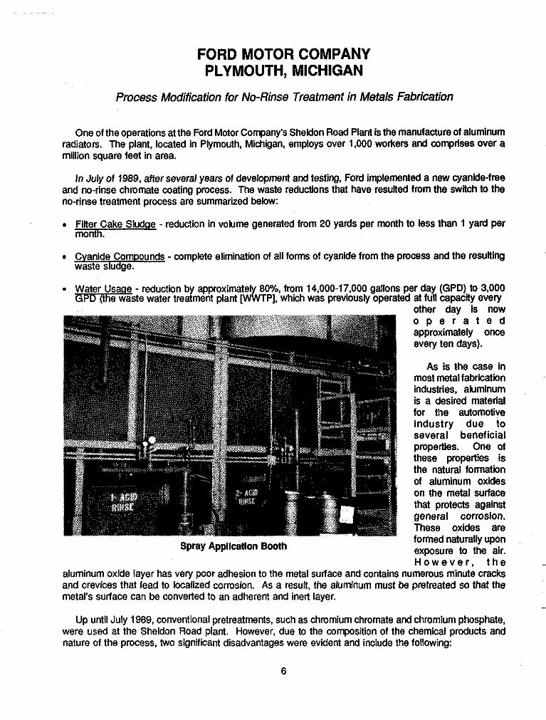
-~ One of the operations at the Ford Motor Company's Sheldon Road Plant is the manufacture of alUminUm radiators. The plant, located in Plymouth, Michigan, employs over 1,000 workers and comprises over a million square feet in area.
In July of 1989, after several years of development and testing, Ford implemented a new cyanide-free and no-rinse chromate coating process. The waste reductions that have resulted from the switch to the no-rinse treatment process are summarized below:
Filter Cake Sludae - reduction in volume generated from 20 yards per month to less than 1 yard per month.
Cyanide Compounds - complete elimination of all forms of cyanide from the process and the resulting waste sludge.
~
~
Water Usa e reduction by approximatel 80%, from 14,000-17,000 gallons per day (GPD) to 3,000 m d s i e water treatment plant [ v\K;vr PI. which was previously operated at full CaDacitv evely
Spray Appllcatlon Booth
other day is now o p e r a t e d approximately once every ten days).
As is the case in most metal fabrication industries, aluminum is a desired material for the automotive industry due to several beneficial properties. One of these properties is the natural formation of aluminum oxides on the metal surface that protects against general corrosion. These oxides are formed naturally upon exposure to the air. H o w e v e r , t h e __
aluminum oxide layer has very poor adhesion to the metal surface and contains numerous minute cracks and crevices that lead to localized corrosion. As a result, the aluminum must be pretreated so that the metal's surface can be converted to an adherent and inert layer.
Up until July 1989, conventional pretreatments, such as chromium chromate and chromium phosphate, were used at the Sheldon Road plant. However, due to the composition of the chemical products and nature of the process, two significant disadvantages were evident and include the following:
6

1) These conventional pretreatments contain ferricyanide, an extremely stable iron-cyanide complex, that, although in this form has not been demonstrated to be a particularly hazardous material, is very difficult to destroy.
2) Conventional pretreatments require rinsing following treatment to halt the chemical reactions and remove residual reactants and reaction products from the surface.
Aluminum finishes typically remove the residual ferricyanide from rinse water by precipitation in a wastewater treatment plant with the chemically reduced chromate residual waste. This treatment results in a waste sludge containing from 0.1 to 0.5% total cyanide, which can not be disposed of in landfills due to the US EPA Land Disposal Restrictions.
Although it may have been possible to destroy the cyanide in the sludge through chemical reaction with chlorine at high temperatures over an extended period of time, Fords approach was to address the iron cyanide issue at its source, the coating process.
Control Panel for Automated System
When switching to the no-rinse coating process, the Sheldon Road Plant continued to utilize the same large booth that had always been used for the spray application (see photo on previous page). However, the new system allowed for the elimination of two rinse stages, thus allowing room within the spray booth to install piping and collection equipment that would allow for c o l l e c t i o n a n d repeated reuse of the new t r e a t m e n t chemical. After the coating product is applied, it is blown off, collected and recycled via gravity
drained PVC piping back into the system. Other modfications included adding controls for automatic sampling and replenishment of a precise waterkhemical mixture; thus, achieving a very consistent application and minimizing the amount of product used (see photo above). The modification of Fords seven zone process for pretreatment of aluminum is shown diagrammatically on the next page as a comparison to the old system.
The switch to a no-rinse treatment process has utilized both source reduction and recycling techniques, without compromising the integrity of the coating application. Now, as the new mixture is applied, the water
7
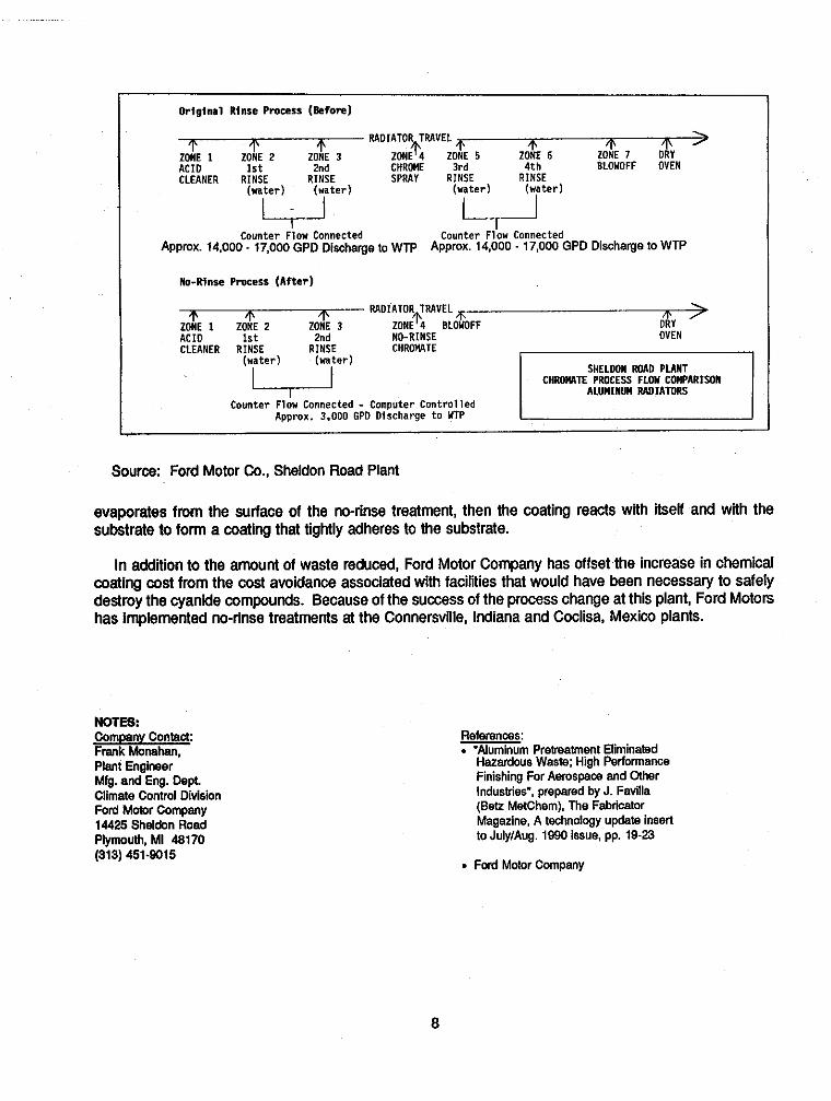
original R inse Process (Before)
RADIATOR TRAVEL ZONE + 7 DRY 1 \ > - ZONE 1 ZONE 2 ZONE 3 ZONE + 4 ZOtE 5 ZOtE 6
ACID 1 s t 2nd CHROME 3 r d 4 t h CLEANER RINSE RINSE SPRAY RINSE RINSE
BLOWOFF OVEN
(water ) (water ) (water ) ( w a t e r )
Counter Flow Connected Counter Flow Connected Appmx. 14,000. 17,000 GPD Discharge to WTP APPmx. 1 4 , 0 0 0 ~ ~ 7 , 0 0 0 GPD Discharge 10 WTP
No-Rinse Process ( A f t e r )
RADIATOR TRAVEL ~- 1' ZONE 1 ZONE 2 ZONE 4 BLOWOFF ACID 1 s t 2nd NO-RINSE CLEANER RINSE RINSE CHROMRTE
(water ) (water )
Counter Flow Connected - Computer C o n t r o l l e d Approx. 3.000 GPO Discharge t o YTP
SHELDON R M D PUNT
ALUMINUM MDIATORS C H M T E PROCESS FLOH COMPARISON
Source: Ford Motor Co., Sheldon Road Plant
evaporates from the surface of the no-rinse treatment, then the coating reacts with itself and with the substrate to form a coating that tightly adheres to the substrate.
In addition to the amount of waste reduced, Ford Motor Company has offset the increase in chemical coating cost from the cost avoidance associated with facilities that would have been necessary to safely destroy the cyanide compounds. Because of the success of the process change at this plant, Ford Motors has implemented no-rinse treatments at the Connersville, Indiana and Coclisa, Mexico plants.
NOTES:
Plant Engineer Mfg. and Eng. Dept. Climate Control Division Ford Motor Company 14425 Sheldon Road Plymouth. MI 48170 (313) 451-9015
References: . "Aluminum Prelreattnent Eliminated Hazardous Waste: High Performance Finishina For Aemsmce and Other Induslri&, prepared by J. Favilla (Bet? MetChem), The Fabricator Magazine, A technology update insert to July/Aug. 1990 issue, pp. 19-23
. Ford Motor Company
8
GARDEN WAY, INC. TROY, NEW YORK
Elimination of Solvent Wastestreams in the Manufacturing of Power Eqoipment via Switch to Powder Paint Technology
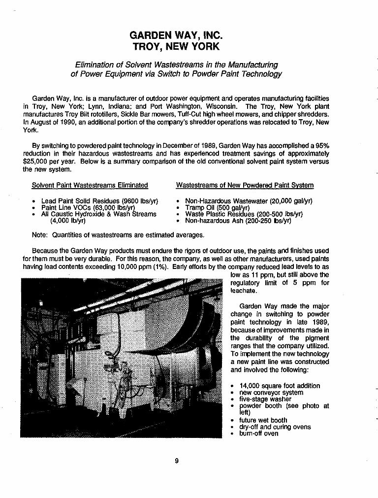
Garden Way, Inc. is a manufacturer of outdoor power equipment and operates manufacturing facilities in Troy, New York; Lynn, Indiana; and Port Washington, Wisconsin. The Troy, New York plant manufactures Troy Bilt rototillers, Sickle Bar mowers, Tuff-Cut high wheel mowers, and chipper shredders. In August of 1990, an additional portion of the company’s shredder operations was relocated to Troy, New York.
By switching to powdered paint technology in December of 1989, Garden Way has accomplished a 95% reduction in their hazardous wastestreams and has experienced treatment savings of approximately $25,000 per year. Below is a summary comparison of the old conventional solvent paint system versus the new system.
Solvent Paint Wastestreams Eliminated Wastestreams of New Powdered Paint Svstem
Lead Paint Solid Residues (9600 Ibs/yr) Non-Hazardous Wastewater (20,000 gavyr) Paint Line VOCs (63,000 lbs/yr Tramp Oil (500 gay r) All Caustic Hvdroxide & Wash s treams 9 Waste Plastic Residllles (200-500 Ibs/vr) .,
(4,000 lb/ir) Non-hazardous Ash (20&25Oibs/yr)
Note: Quantities of wastestreams are estimated averages.
Because the Garden Way products must endure the rigors of outdoor use, the paints and finishes used for them must be very durable. For this reason, the company, as well as other manufacturers, used paints having lead contents exceeding 10,000 ppm (1%). Early efforts by the company reduced lead levels to as
low as 11 ppm, but still above the regulatory limit of 5 ppm for leachate.
Garden Way made the major change in switching to powder paint technology in late 1989, because of improvements made in the durability of the pigment ranges that the company utilized. To implement the new technology a new paint line was constructed and involved the following:
14,000 square foot addition new conveyor system five-stage washer
future wet booth 9 dry-off and curing ovens 9 bum-off oven
owder booth (see photo at pert)
9

Bringing the new paint line into production took Garden Way approximately 8 months (including construction time). The capital cost associated with the new system was approximately $1.25 million and the payback time was originally estimated at 10 years, but may actually be as soon as 5 years.
Initially the project was designed to obtain a higher quality product, improve flexibility and increase production capacity. The new system afforded Garden Way the improved ability to handle new stocks of galvanized material for new product lines. Reducing the company's hazardous wastestreams and permit
tap water rinse; iron phosphate stage; a second rinse; non-chrome sealer; drying off stage (250' F); a powder booth; and curing oven (400" F). The new powder paint process used at Garden Way is shown diagrammatically below.
___ ~
costs were noted additional benefits. The new system layout consists of a low pH hydroxide wash: clean -~
~
FLOW DIAGRAM OF POWDER PAINT SYSTEM
Powder paint, essentially afine, semi-polymerized polyester dust (3-10 microns), is applied by automatic and manual electrostatic spray guns. The majority of the overspray (97-98%) is contained within the powder booth and recycled via an inherent pump system. The collected powder is returned to the fill hopper and reused. The 2-3% powder that becomes contaminated with dust from outside the spray booth is collected in a High Efficiency Particulate Air Fiber (HEPA) vac and cured to form a non-hazardous disposable plastic. The powder coated part is baked so that the coating melts into a durable, high gloss plastic/polyester finish. Improperly painted parts are cleaned in a 1200" F oven equipped with a 1400" F afterburner, and the small quantity of non-hazardous ash is sent to a sanitary landfill.
The non-hazardous disposable residues go to a sanitary landfill, as does the ash (the Toxic Characteristic Leachate Procedure showed the ash to be non-hazardous). The tramp oils are paraffin- and petroleum-based oils that are present on the metal stocks when received in shipment (for protective purposes). The oils are collected as float during stock washing operations and are sent to a repmcessor for recovery and reuse, either as lube oil or for fuel blending.
__
___
10

The photograph above shows the unpainted parts entering the Powder Paint Wash System (foreground) and finished powder-painted parts leaving the 400degree F Caving Oven and Cooling Tunnel.
NOTES: Company Contact: Paul Hoffmann Mgr., Environmental Services Garden Way, Inc. 102nd Street and 9th Ave. Troy, New York 12180 (518) 235-6010
References: . "Garden Way, Inc., Troy, New York Plant. Hazardous Waste Reduction- Powdered Paint Line". by P. Hoffmann. presented at the New'York State Third Annual Waste Minimization Conferenw June. 1990, Albany, NY.
- Garden Way, Inc.
11

TRW, ROSS GEAR DIVISION GREENEVILLE, TENNESSEE
Elimination of Hazardous Solvent Waste Generation Via Ultrasonic Cleaning Technology for the Manufacturing of Hydraulic Components
The ROSS Gear Dlvision of TRW Inc. is a manufacturer of hydraulic motors, hydrostatic steering units, and manual steering gears. The hydrostatic steering units are used in off-highway vehicles such as farm equipment (e.g., tractors and combines) and the manual steering gears are used in large highway trucks. The company employs approximately 350 people at the Greeneville Plant, which comprises 281,920 square feet. The plant has been in operation since June of 1972.
To reduce wastes associated with one of their processes, TRW replaced the method by which they remove lapping compound from the parts (December of 1987) and more recently (1989) switched to a water-based lapping solution. As well as eliminating the potential health hazards that were associated with the old solvent vapor degreasing system, TRW has achieved a 50% reduction in the overall quantity of hazardous waste generated at the Greeneville plant and has, in turn, significantly decreased disposal costs. This reduction in hazardous waste generated is shown graphically below
~
The fluid power c o m p o n e n t s manufactured at the Greeneville facility are extremely sensitive to contamination by dirt and the abrasive solutions used to c l e a n t h e components. For instance. if hydraulic motor components that were not properly c l e a n e d w e r e installed in a vehicle, the entire hydraulic system of that vehicle could be affected since the fluid is pumped throughout the entire system. For this reason, TRW
70
60
50
40
30
20
10
0
HAZARDOUS WASTES TOTAL GENERATED 1981 - 1988
Thousands 01 Iba.
1981
42.1 I
1982 1983
59.8
1984
41.4
1985
42.2
I986
44.2 -
1987 I988
OTHER WASTES TCE WASTES
must meet cleaning specifications that are required by their clients.
To improve the surface finish of their parts. TRW uses an intensive machining process referred to as lapping. The lapping process utilizes an abrasive media that must be completely removed from the parts after the finishing operation. The lapping material that had been used at the Greeneville Piant was a sluny consisting of fiie-micron silicon grit and an oil carrier.
Prior to late 1987 the company used a solvent vapor degreasing system to remove the lapping compound from the parts. Trichloroethylene (TCE), the solvent used, worked well but generated
__
__
12

wastestreams that included (1) hazardous still bottoms from in-house distillation of TCE, (2) hazardous waste filtration powder (containing residual TCE), and (3) stack and fugitive emissions containing TCE.
The amount of wastes generated by these wastestreams was significant. For instance, in 1987 the Greeneville plant generated approximately 14,090 pounds of TCE still bottoms, 3,740 pounds of filtration powder, and an estimated 50,300 pounds of fugitive and stack emissions. The TCE still bottoms were transported offsite to a hazardous waste treatment and disposal faciliiy and the filtration powder was sent offsite for incineration.
Because of the health and environmental concerns associated with the TCE, the company began investigating feasible alternatives to solvent degreasing in 1986. Extensive research and evaluation culminated in the discontinued use of TCE in December 1987. The alternative process chosen involved the use of an aqueous alkaline solution (a cleaning agent) in conjunction with ultrasonic cleaning.
T h r o u g h a contractor, TRW designed and built a three-stage ultrasonic system washer. The system consists of three primary steps which include an ultrasonic cleaner tank, a water rinse dip tank, and a Rlst inhibitor treatment tank. The parts are transported to the s y s t e m v i a a conveyor line (see photo to left) and are p l a c e d i n t h e ultrasonic cleaning tank where sound w a v e s a r e
propagated through an alkaline solution by way of transducers. The transducers are small piezoelectric devices that are encased in stainless steel and are placed at the bottom and sides of the cleaning tank. These sound waves, which are in lieu of agitation, impinge on the parts with sufficient energy to satisfactorily clean the parts. The alkaline solution is a product of Calgon and was chosen after testing the system with several formulations. A surfactant is a necessary component used in conjunction with TRWs ultrasonic system to properly loosen the lapping compound from the parts.
The non-hazardous waste from the rinse dip tank is sent to an ultrafiltration unit, which handles wastestreams from other plant processes as well. Both residuals from the ultrafiltration unit, namely oils that came from other plant operations, and alkaline solution are non-hazardous. The oils are sent offsite to a treatment facility and the aqueous solution is discharged to the sanitary sewer.
TRW has continually been refining the new system since it first replaced solvent degreasing. In 1989 the company added more transducers to the ultrasonic cleaning stage to improve the cleaning efficiency. They also recently switched from an oil-based lapping solution to a water-based aluminum oxide solution. By making this change, the plant has eliminated the need for using mineral spirits, which were used for the parts precleaning.
13

The plant has just added special filters to the ultrasonic cleaning solution which will stabilize the amount of particulates in the cleaning solution at a level which is optimum for the best cleaning resuits. As shown in the photo to the right, there is one filter for each of the three tanks that comprise the system.
TRW is involved with the University of Tennessee Center for Industrial Services. T h r o u g h t h i s organization, TRW has been able to transfer their acquired know-how of ultrasonic cleaning systems to other companies in the State of Tennessee that have similar cleaning operations.
NOTES Company Contact: Frank HartmanlCHMM Environmental Coordinator TRW, Ross Gear Division P.O. Box 1790 Greeneville, TN 37744-1790 (615) 639-8151
Other: References: - . TRW. Ross Gear Division Winner of the state of Tennessee 1988 Governor's Award for . Governors Award Nomination Excellence in Hazardous Waste
Information Management
14

PERRY BUILDERS, INC. HENDERSON, NORTH CAROLINA
Process ModificatiodProcedoral Changes for Reduction of Hazardous Waste Generafed in Treatment of Lumber
Peny Builders, Inc. is a family owned and operated corporation that treats lumber used for building outdoor structures that are exposed to the weather (e.g., outdoor decks, fences, boat docks, etc.). The Raleigh Road Plant i n Henderson, NC was established in July of 1985 and employs approximately 20 people.
To minimize the accumulation of hazardous wood treatment waste, Perry Builders implemented several steps involving equipment and process changes, starting in 1987 and continuing up through 1989. These changes, which have resulted in an annual waste drum reduction from 14 to 2, and associated 80% waste disposal cost savings, include (1) installation of a vacuum pump to achieve a dlyer lumber, thus reducing drippage; (2) procedural change of paying wood treaters from a per unit to an hourly basis; (3) extension of the time period for the final vacuum process; and (4) installation of a roof atop the treated lumber storage area.
The Raleigh Road Plant pressure treats wood products with a mixture of chromated copper arsenate (CCA). a wood preservative, and water. To minimize worker exposure to the CCA, all functions associated with the receipt, transfer, storage, and application of the treatment solution are conducted in a contained area. The treatment application is conducted in a treatment cylinder. This cylinder (shown in the above photo) is 46 feet in length and 6% feet in diameter. "Lumber packs", approximately 2 feet high, are rolled into the treatment cylinder on "rail cars", the door to the cylinder is closed and the chamber is flooded with the treatment solution. A computer is utilized for determining the proper amount of treatment solution added to the amount of wood inserted into the chamber.
During the treatment process, any excess CCA solution that drips off the wood is mixed with sawdust, wood chips and dirt. As a result, any excess wlution that has been contaminated with those particulates becomes a listed hazardous waste, classified as DO04 and D007. This excess flows from a drip pad that slopes back to the "door pit", which is a concrete pit at the front of the treatment cylinder.
The basis for Peny Builders implementing the three time-related steps (as previously listed above) is to keep the treatment solution in the treated wood within the cylinder; thus, preventing the solution from dripping from the wood and coming in contact with the particulates that result in the generation of hazardous waste. The new vacuum pump installed is vefv powerful and results in a faster and stronger
15

vacuum, which in turn results in a reduction of drippings of CCA solution. After the lumber packs are rolled into the treatment chamber, the door is closed and the cylinder is flooded with solution and pressure is applied for 15 minutes to force treatment solution into the wood. Aftenwards, the valves on the cylinder are opened and the vacuum is applied to force any excess treatment solution out of the wood.
Due to the stronger vacuum and increased time applied, the treated wood that exits the cylinder is a lot dryer than the wood treated by the process used in the past. The management decision to increase the vacuum time and to pay wood treaters on an hourly basis (rather than a per unit basis as was done previously) has encouraged the achievement of a dry lumber product.
The fourth step taken, installation of a roof above the treated lumber storage area, is a post-treatment preventative measure. CCA takes approximately 48 hours to be fixed in the wood cells. Until this time, the roof prevents any potential leaching of the treatment compound by rain. Once the copper and arsenate are bonded into the wood cells, the treated wood is virtually leach proof, according to Vice President, Leon Perry, 111.
___ ~~
-
~
The volume reduction and associated cost savings from the measures implemented by Perry Builders, Inc. are summarized below.
SUMMARY OF SOURCE REDUCTION
#of Drums Disposal &&r Generated - costs % Saved
1987 1988 1989
14 $2,380 __ 10 $1,500 37 2 $ 300 80
The photo at the right shows the new vacuum pump adjacent to the w w d treatment cylinder.
NOTES: ~~
Company Contact: Other Contacts: References: Leon W. Perry, 111, Vice President Pew Builders, Inc.
Gary Hunt 8 Stephanie Richardson N. Carolina De~t . of Envimnmental.
. Entry Form - State of N.C. __ Govemovs Award of Excellence
Raleigh Road South Health and Nahral Resources - ' for Outstanding Achievements in P.O. Box 589 Pollution Prevention Program Waste Management Henderson, NC 27536 (919) 492-9171 Raleigh, NC 27611 Perry Builders, Inc.
P.O. Box 27687
(919) 733-7015
16

KINNEAR DOORNVAYNE-DALTON CORPORATION CENTRALIA, WASHINGTON
Recycling of Wastewater Via Product Substitution of Glue Formulations in the Lumber Products Industry
Kinnear DoorMlayne-Dalton Corporation, located in Centralia, Washington, is a manufacturer of wooden parts for overhead garage doors. The company employs as many as 100 workers in the Centralia plant, which handles approximately 13 to 14 million board feet of lumber annually. Manufacturing processes used at the plant involve drying, milling, jointing, and gluing wood parts to form the building products.
As a result of several inexpensive measures implemented by Kinnear Door, the company now reuses much of its glue washdown water to mix up new glue formulations. Prior to this, all of the wastewater was disposed. At a startup cost of $1,500, for purchase and installation of the new equipment, Kinnear Door has saved an estimated $1,000 per year in permit fees, $300 per month in sewer fees, $2,000 per year in landfill disposal fees, and $10,000 a year in pretreatment costs.
T h e p r i m a r y w a s t e s t r e a m associated with the manufacturing of the w o o d p a r t s i s wastewater containing g lue washdown water. Early in the company's history, which dates back to 1963, the wastewater was disposed of in a s e p t i c s y s t e m designed for that purpose. However, due to environmental regulations, the company began using the septic tank(s) to store the wastewater. It was anticipated that the wastewater would eventually be taken by a septic pumper to a local landfill and spray@.
More recent regulations, which prohibited disposal of the wastewater at landfills, eliminated the aforementioned option. Thus, with the help of the State of Washington Department of Ecology, Kinnear Door investigated alternative means for disposing of the wastewater that was being generated at a rate of up to 2,500 gallons per month. Options considered included treatment systems involving settling ponds and evaporators for pretreatment and ultimate treatment at a local sewage treatment plant.
However, the initial remedies considered were determined to be undesirable. Treatment systems would have to be evaluated for environmental permitting, and the cost of pretreatment chemicals and the
17

associated analyses necessary to determine the suitability of disposing of the wastewater at the local sewage treatment plant was estimated to be $10,000 annually. Ultimately, the solution to the company’s problem came from self-evaluation of the washwater. Because the melamine-urea and PVA glues being used were water-based, the employees themselves pursued the possibility of reusing the glue washdown water to mix up their glue (formulations), thus reducing the volume of wastewater generated at the source. The company decided to purchase dry glues to replace the liquid glues that had always been used. Water was not added to the already-mixed liquid glues; however, water was needed for mixing up glue formulations from the dry glues. Thus, the employees figured that a good portion of the mixing water used could be wastewater. -~
The system that was developed to implement this change (in October 1989) was fairly simplistic and involved two barrels to hold the wastewater, pumps, and a fiberglass settling tank. This glue washwater recycling system setup is shown in the photo on the previous page.
To extend the pot l ie of the glue, the employees determined what proportion of fresh water and recycled water were needed to attain the proper pH. It was determined that 10 pounds of water needed to be added to the dry glues, 6 pounds could be wastewater and 4 pounds fresh water.
___ ~~
-
This photograph shows the lining of a 3-gallon glue mixing pot, which has eliminated generation of rinse water.
Besides adding the tanks, the company line their 3-gallon glue mixing pots with plastic trash compactor bags, which has eliminated rinsing (see photo at left). At the end of each day, the company now tip the lined pots upside down and empty remaining wet glue into a 55 gallon drum. Once the glue sets up in the drum, lt is immobile and can be sent to a sanitary landfill. Prior to using the plastic liners, the glue pots had to be rinsed to prevent buildup of dried glue. T h e w e t g l u e contaminated rinse water cannot be sent to a landfill, thus the plastic liners have precluded Kinnear Door __ from h a v i n g t o construct expensive glue/water separation s t r u c t u r e s ( i e . evaporation pond).
~
__
18

The primary wastestream generated at the manufacturing plant now consists of non-hazardous glue solids that settle out of the wastewater in the settling tank and are drained out of the glue pots. These drummed glue solids are sent to a local landfill.
NOTES: Comparw Contact: John Ver Valen Kinnear DoorNVavne- Dalton Corporati& 2001 Industrial Drive Centralia. WA 98531 (206) 736-7651
Other Contact: Judy Kennedy State of Washington Department of Ecology PV-11 Olympia, WA 98504-871 1 (206) 459-6356
.
References: , "Success Thmugh Waste
Reduction: Proven Techniaues fmm Washington Businesses", Washington State Department of Ecology. Publication 90.22, pp. 5-6.
Washington State Department of Ecology
Kinnear DoorNVaynoDalton Corp.
19

U.S. DRY CELL BATTERY MANUFACTURING INDUSTRY
Reduction in Toxicity in Dry-Cell Batteries via Product Substitution
he ~ r y Battery sect ion of the National Electrical M a n u f a c t u r i n g Association (NEMA) r e p r e s e n t s c o m m e r c i a l household battery manufacturers located in the United States. Members include such companies as Eveready Battery Company, Duracell USA, R a y o v a c Corporation, and Kodak. Several years ago, the U.S. battery i n d u s t r y , i n conjunction with NEMA, adopted a source reduction strategy for reducing the amounts of mercury and cadmium used in battery production. A source reduction option was preferred over recycling due to logistical and safety concerns relating to battery collection facilities.
As a result of the individual efforts of dry-cell battery manufacturers, members of the NEMA Dry Battery Section have achieved successful source reduction of toxicity in dry-cell batteries. The table on the next page shows the steadily decreasing volumes of mercury occurring in batteries over the past six years. The table also shows how batteries, as a whole, have contained the largest amount of mercury of any product in the US.; thus, the reduction of mercury in batteries will have a significant impact on the amount of mercury in consumer products.
According to U.S. Bureau of Mines data, the US. battery industry decreased its total consumption of mercury by 91% during the five years from 1984 to 1989, while all other users combined increased their consumption by 25% during the same time period. In the U.S. production of household batteries (used by consumers for their personal needs), mercury usage has fallen from 778 tons in 1984 to a projected 62 tons in 1989, a decrease of 92% in just six years. For calendar year 1990, NEMA estimates that the percentage of total United States mercury consumption going into household battery production will be around 5%.
Mercury has historically been used in non-rechargeable batteries to coat zinc. Zinc is used as the negative electrode material in five types of household batteries (shown in the table on the next page).
The zinc anodic material added in alkaline-manganese batteries is in a powdered form. Small amounts of mercury (an estimated 1-3% by weight) have, in the past, been mixed with the powdered zinc to prevent the zinc from reacting with other battery ingredients. The mercury combines with the zinc to form a
20
-
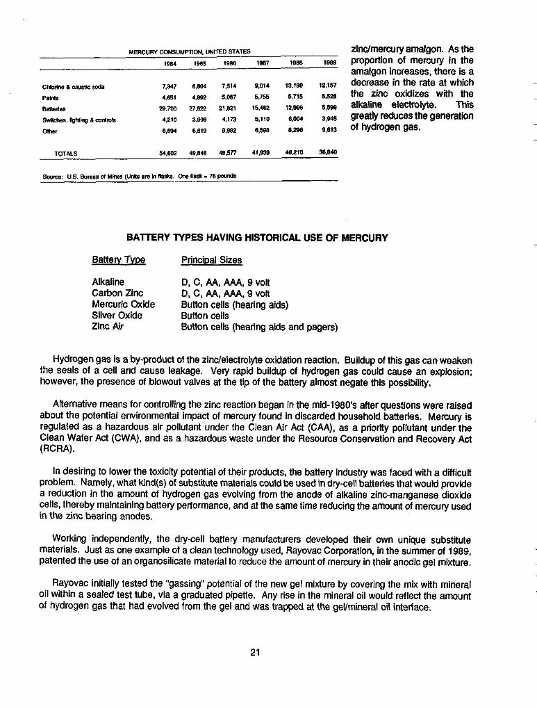
MERCURY CONSUMPTION. UNITED STATES zinclmercury amalgon. As the 1984 1887 1088 IWO proportion of mercury in the
amalgon increases, there is a
BAlTERY TYPES HAVING HISTORICAL USE OF MERCURY
Battetv TvDe Principal Sizes
Alkaline Carbon Zinc Mercuric Oxide Silver Oxide Button cells Zinc Air
D, C, AA, AAA, 9 volt 0, C, AA, AAA, 9 vol Button cells (hearing aids)
Button cells (hearing aids and pagers)
Hydrogen gas is a by-product of the zindelectrolyte oxidation reaction. Buildup of this gas can weaken the seals of a cell and cause leakage. Very rapid buildup of hydrogen gas could cause an explosion: however, the presence of blowout valves at the tip of the battery almost negate this possibility.
Alternative means for controlling the zinc reaction began in the mid-1980's after questions were raised about the potential environmental impact of mercury found in discarded household batteries. Mercury is regulated as a hazardous air pollutant under the Clean Air Act (CAA), as a priority pollutant under the Clean Water Act (CWA), and as a hazardous waste under the Resource Conservation and Recovery Act (RCRA).
In desiring to lower the toxicity potential of their products, the battery industry was faced with a dificult problem. Namely, what kind@) of substitute materials could be used in dry-cell batteries that would provide a reduction in the amount of hydrogen gas evolving from the anode of alkaline zinc-manganese dioxide cells, thereby maintaining battery performance, and at the same time reducing the amount of mercury used in the zinc bearing anodes.
Working independently, the dry-cell battery manufacturers developed their own unique substitute materials. Just as one example of a clean technology used, Rayovac Corporation, in the summer of 1989, patented the use of an organosilicate material to reduce the amount of mercury in their anodic gel mixture.
Rayovac initially tested the "gassing" potential of the new gel mixture by covering the mix with mineral oil within a sealed test tube, via a graduated pipette. Any rise in the mineral oil would reflect the amount of hydrogen gas that had evolved from the gel and was trapped at the gevmineral oil interface.
21
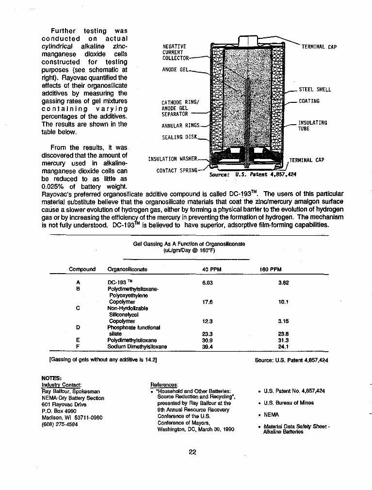
Further testing was conducted on actual cylindrical alkaline zinc- manganese dioxide cells constructed for testing purposes (see schematic at right). Rayovac quantified the effects of their organosilicate additives by measuring the gassing rates of gel mixtures c o n t a i n i n g v a r y i n g percentages of the addlives. The results are shown in the table below.
From the results, it was discovered that the amount of mercury used in alkaline- manganese dioxide cells can be reduced to as little as
NEGATIVE CURRENT COLLECTOR
ANODE GEL
CATHODE RING/ ANODE GEL SEPARATOR
INSULATION WASHER,
ANNULAR RINGS
SEALING DISK,
I U.S. Pate,
STEEL SHELL
-COATING
CAP
0.025% of battery weight. Rayovac's preferred organosilicate additive compound is called DC-193TM. The users of this partiCUlar material substitute believe that the organosilicate materials that coat the zlndmerculy amalgon sulface cause a slower evolution of hydrogen gas, either by forming a physical barrier to the evolution of hydrogen gas or by increasing the efficienc of the mercury in preventing the formation of hydrogen. The mechanism is not fully understood. DC-193 /M . IS believed to have superior, adsorptive film-forming capabilities.
Gel Gassing As A FuIIclion of Organoslliconate (uUgmlDay @ 160°F)
Compound Organoslliconate 40 PPM 160 PPM
A DC-193" 6.03 3.82 B Polydlmethylslloxane-
Polyoxyethylene
C Non-Hyrdolkable Siliconelywl Copolymer 12.3 3.15
D Phosphoate hinctbnal sllate 23.3 23.8
E Polydlmethylsiloxane 30.9 31.3 F Sodium Dimethylsiloxane 39.4 24.1
Copolymer 17.6 10.1
[Gassing of gels wlhout any addlive Is 14.21
NOTES Industry Contact: Ray Ballour. Spokesman NEMA.Dry Battery Section 601 Rayovec Drive P.O. Box 4960 Madison, WI 5371 1.0960 (608) 275-4584
Source: U.S. Patenl4.857.424
References: . "Household and m e r Batteries: Source Reduction and Recycling". presented by Ray Ballour at the 9lh Annual Resource Recovery Conference of the US.
. U.S. Patent No. 4,857,424
. US. Bureau of Mines - NEMA - Material Data Safely Sheet Conference of Mayors, Washington, DC. March 30, 1990 Alkaline Batteries
22

AT&T BELL LABORATORIES/AT&T NETWORK SYSTEMS PRINCETON, NEW JERSEY/COLUMBUS, OHIO
Elimination of Postsolder Cleaning in Printed Circuit Board Manufacturing Via Development of a Low Solid Flux Application Process
AT&T Bell Laboratories (Princeton, NJ) developed a patented process in flux technology which has been implemented at several AT&T manufacturing facilities, including AT&T Network Systems in Columbus, Ohio where telecommunications systems are manufactured. The Low Solids Fluxer (LSF), reported to be a significant advance in flux technology, is available to electronic manufacturing companies other than AT&T. This technology could aid the entire electronic industry in their effort to phase out worldwide chlorofluorocarbons (CFCs) production by the year 2000, as part of an international agreement (the Montreal Protocol).
The Columbus plant was the first AT&T facility to completely convert to the new system (August 1988). By utilizing the LSF-2000 (shown schematically below) to precisely control and monitor low-solid flux coatings, the Columbus plant has reoorted the following source reduction benefits:
&in Control Cabinet
Flux Dcllvery System
AWAICED APPLlCAlO8 OF LOY SOLID FLUXES (Source: l T L 1 Bell Labontortcr)
elimination of excessive flux resulting in elimination of postsolder cleaning processes:
total elimination of the perchloro-ethylene (PCE) postsolder cleaner they had used (a reduction of 30,000 gallons per year): and
reduction in roduct flux material used /&timated at 2,000 gallons).
These achievements, in conjunction with the elimination of monitoring and reporting of hazardous materials losses and elimination for the need of solvent recovery and carbon adsorption facilities, have resulted in cost savings at the Columbus plant estimated at $145,000 per year.
The electronics industry has used solvents containing CFCs and other chlorinated compounds extensively for cleaning components during manufacturing, most notably for removing excess fluxes from printed circuit boards. Flux, a cleaning and wetting agent, is applied prior to soldering to enhance adherence of the solder. Therefore, if application of excess flux can be minimized or eliminated, then the chemicals (which often include CFCs) used to remove excess flux can be minimized or eliminated.
Several no-clean fluxes are available on the market, and are designed to leave minimal residue. These fluxes are categorized as low solid fluxes and contain I-5% nonvolatile material by weight, which is considerably less than the conventional fluxes that typically contain 25-35% nonvolatile solids by weight. Although use of these low solid fluxes without special application methods would significantly reduce flux residues, extensive research by AT&T indicated that even these small amounts of residue may present
23
problems relating to prodbct reliability. Thus, the LSF applicator was designed to eliminate all residues to Insignificant levels.
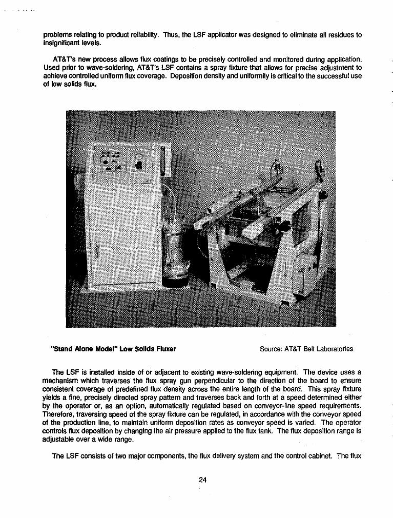
AT&T's new process allows flux coatings to be precisely controlled and monitored during application.
achieve controlled unitorm flux coverage. Deposition density and uniformity is critical to the successful use of low solids flux.
___ Used prior to wave-soldering, AT&T's LSF contains a spray fixture that allows for precise adjustment to
~~
-
"Stand Alone Model" Low Sollds Fluxer Source: AT&T Bell Laboratories
The LSF is installed inside of or adjacent to existing wave-soldering equipment. The device uses a mechanism which traverses the flux spray gun perpendicular to the direction of the board to ensure consistent coverage of predefined flux density across the entire length of the board. This spray fixture yields a fine, precisely directed spray pattern and traverses back and forth at a speed determined either by the operator or, as an option, automatically regulated based on conveyor-line speed requirements. Therefore, traversing speed of the spray fixture can be regulated, in accordance with the conveyor speed of the production line, to maintain uniform deposition rates as conveyor speed is varied. The operator controls flux deposition by changing the air pressure applied to the flux tank. The flux deposition range is adjustable over a wide range.
The LSF consists of two major components, the flux delively system and the control cabinet. The flux
__
__
24

delivery system which is comprised of a self-cleaning spray gun, traverse mechanism, and exhaust hood with safety sensors, is mounted in the wave-soldering machine. The free-standing control cabinet contains all electrical and pneumatic control systems. An easy-to-use operator control panel provides visual and audible feedback when operator intervention is required.
To control flux vapor, the LSF contains an exhaust system. The LSF's hood is designed to capture and remove flux overspray. To prevent flux vapor build-up, a sensor automatically shuts down the system when the exhaust hood is removed and an air-flow sensor shuts down the system when there is no air flow in the exhaust.
The consistency of AT&T's most advanced flux applicator is reported to allow for a uniformity with f15% variation and a repeatability of *IO%. Topside deposition and residue are undetectable. The solderability of the board is reported to be greatly increased while allowing subsequent soldering processes to yield consistent topside fillets.
.
NOTES: Companv Contacts: Magit EloGenthedHead of MTG Manufacturina Tech G r o w (Developer) (669) 639-2238 and'
Dr. Leslie A. GuthElux Expert (609) 639-3040 ATBT Bell Laboratories Engineering Research Center P.O. Box 900 Princeton, NJ 08540 (609) 639-3040
Girish Parikh, Sr. Engr. ATBT Network Systems 6200 East Broad Street Columbus, OH 43213 (614) 860-5594
Re fe re n ce s : "To Clean or Not to Clean? ATBT Studies the Behavlor of Low-Solids (no-clean) Fluxes", by Leslie A. Guth. Circuits Manufacturing, Vol. 29, No. 2, p. 59, February 1989.
. Nomination Information for Annual Govemor's Award for Outstanding Achievement in Pollution Prevention (State of New Jersey), submined by ATBT, February 1991.
'Elimination of Perchloroethylene in Wave Soldering Using Low Solids Fluxef. Presented by G.D. Parib and G.M. Renner at the National Electric Packaging and Production Conference, Anaheim, CA, February 27, 1990.
25

BURKE MILLS, INC. VALDESE, NORTH CAROLINA
Minimization of Waste Solvent and Recycling of Solid Waste in the Textile Industry Through Recovery and Reuse
___ ~~
-
Burke Mills, Inc. - Frank Gaddy Yarn Division, located in Valdese, North Carolina, is a yarn plant that -~ employs approximately 325 people. The plant produces high twist filament yam for the neckwear emblem and sewing thread industries. The company is also involved in texturing of polyesters and has a dyehouse for spun yarn, filament yam and stretch nylon.
The plant uses the solvent l.l,l-trichloroethane (l,l,l-TCA) for removing greases and oils from yarn cleaning machinery parts. In the spring of 1985, the company determined that they were contaminating approximately 450 gallons of l,I,l-TCA with either the oils and greases, or dyes and chemicals from cleaning the finished product. Proper disposal of the spent solvent cost $650 per 55 gallon drum.
Through bulk purchasing of the l,I,l-TCA in 3,000 gallon shipments versus 55 gallon drums, the company saved approximately $1 1,330 annually. Improved management practices (e.g., establishment of a central distribution area) implemented by the company, coupled with the purchase of a distillation unit, has resulted in better than 90% reclamation of 1 ,l,l-TCA solvent. As a result, the amount of hazardous waste being disposed has decreased from 5,400 gallons annually to approximately 55 gallons annually, with an associated cost reduction from $63.168 annually to $650 annually. Total annual savings was reported to be $99,964, which resulted in a payback period of less than one month.
The company pined the South East Waste Exchange in May of 1985 and became aware of the solvent distilling unit at a seminar. The company purchased the LS-15 Little Still (manufactured by Finish Engineering Co., Inc. of PA) for $6,800 after visiting other industries that used the apparatus for recycling other chemicals.
Even prior to purchase of the distiller, Burke Mills made a significant change in the purchasing of the solvent. By utilizing an existing 6,000 gallon, stainless steel tank, the company was able to acquire solvent in 3,000 gallon shipments. By eliminating drum storage and handling, a central distribution area was established which improved control over the chemical and led to safer conditions.
~
The distilling unit (shown at right) operates at a low pressure and has a 15 gallon capacity per cycle run. The spent solvent is sent through the recovery process. After completion of the cycle, the reclaimed solvent is collected into designated containers and is tested by a certified operator before being issued for use.
In addition to this solvent reclamation project, the Burke Mills plant is also involved in the recycling of plastic cylindrical tubes that are the base of the yam, dirty and excess waste yarn and cardboard. As a
-
-
26
result they have significantly reduced the solid waste that would go to the Burke County landfill.
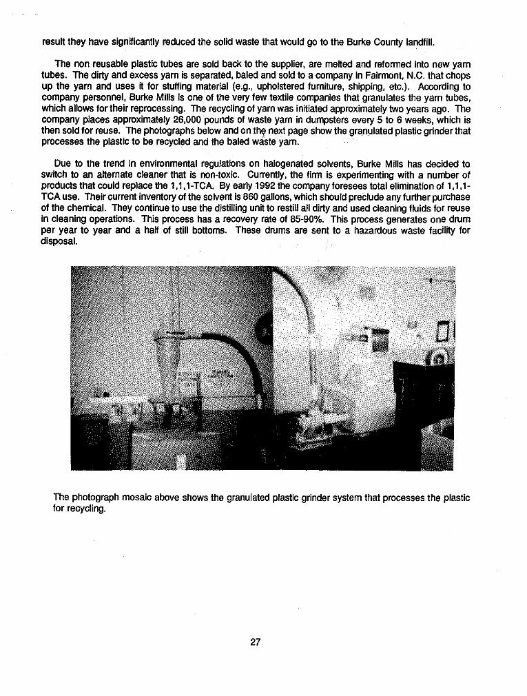
The non reusable plastic tubes are sold back to the supplier, are melted and reformed into new yarn tubes. The dirty and excess yarn is separated, baled and sold to a company in Fairmont, N.C. that chops up the yarn and uses it for stuffing material (e.g., upholstered furniture, shipping, etc.). According to company personnel, Burke Mills is one of the very few textile companies that granulates the yarn tubes, which allows for their reprocessing. The recycling of yarn was initiated approximately two years ago. The company places approximately 26,000 pounds of waste yarn in dumpsters every 5 to 6 weeks, which is then sold for reuse. The photographs below and on thq next page show the granulated plastic grinder that processes the plastic to be recycled and the baled waste yarn.
Due to the trend in environmental regulations on halogenated solvents, Burke Mills has decided to switch to an alternate cleaner that is non-toxic. Currently, the firm is experimenting with a number of products that could replace the 1,1 ,I-TCA. By early 1992 the company foresees total elimination of 1,1,1- TCA use. Their current inventory of the solvent is 860 gallons, which should preclude any further purchase of the chemical. They continue to use the distilling unit to restill all dirty and used cleaning fluids for reuse in cleaning operations. This process has a recovery rate of 85-90%. This process generates one dwm per year to year and a half of still bottoms. These drums are sent to a hazardous waste facility for disposal.
The photograph mosaic above shows the granulated plastic grinder system that processes the plastic for recycling.
27

The photograph below shows the consolidated waste yarn that is reused for other applications.
NOTW: Comoanv Contact: Other Contacts: Ray Shuping Burke Mills, Inc. - Frank Gaddy Yarn Division Sterling St.. P.O. Box 190 Valdese. NC 28690 P.O. Box 27687 Board.
References: . EnIrant Form information submitted
to the State of North Carolina Governor's Waste Management
Gary Hunt & Stephanie Richardson N. Carolina Dept. of Environmental, Health and Natural Resources - Pollution Prevention Program
(704) 874-2261 Raleigh, NC 2761 1 (919) 733-7015 . Burke Mills, Inc.
Other: Winner of 1988 Governofs Award of Excellence for Outstandina
-
Achievement in Hazardous Waste Management - Small Industry Category.
28
AMITAL SPINNING CORPORATION NEW BERN, NORTH CAROLINA
Recycling and Reuse of Process Water/Reduction in Dyebath Chemical Usage Via Automated Controls
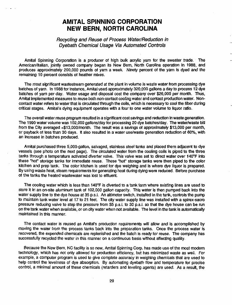
Amital Spinning Corporation is a producer of high bulk acrylic yarn for the sweater trade. The Americanlltalian, jointly owned company began its New Bern, North Carolina operation in 1988, and produces approximately 200,000 pounds of yarn a week. Ninety percent of the yarn is dyed and the remaining 10 percent consists of heather mixes.
The most significant wastestream generated at the plant in volume is waste water from processing dye batches of yarn. In 1988 for instance, Amital used approximately 320,000 gallons a day to process 12 dye batches of yarn per day. Water usage and disposal cost the company over $26,000 per month. Thus, Amital implemented measures to reuse both non-contact cooling water and contact production water. Non- contact water refers to water that is circulated through the coils, which is necessary to cool the fiber during critical stages. Amital's dying equipment operates with a four to one water volume to liquor ratio.
The overall water reuse program resulted in a significant cost savings and reduction in waste generation. The 1990 water volume was 102,000 gallons/day for processing 20 dye batchedday. The water/waste bill from the City averaged <$13,00O/month. The result was a savings of approximately $13,000 per month, or payback of less than 30 days. It also resulted in a water usdwaste generation reduction of 60%, with an increase in batches produced.
Amital purchased three 5,000-gallon, salvaged, stainless steel tanks and placed them adjacent to dye vessels (see photo on the next page). The circulated water from the cooling coils is piped to the three tanks through a temperature activated diverter valve. This valve was set to direct water over 14OoF into these "hot" storage tanks for immediate reuse. These "hot" storage tanks were then piped to the color klchen and prep tank. The color kitchen is used for dye weighing and is where dye liquor is prepared. By using waste heat, steam requirements for generating heat during dying were reduced. Before purchase of the tanks the heated wastewater was lost to effluent.
The cooling water which is less than 140°F is diverted to a tank farm where existing lines are used to store it in an on-site aluminum tank of 102,000 gallon capacity. This water is then pumped back into the water supply line to the dye house at 35 p.s.i. An altimeter switch, installed in the tank, controls the pump to maintain tank water level at I7 to 21 feet. The cEy water supply line was installed with a spirex-sacro pressure reducing valve to step the pressure from 55 psi . to 30 ps i . so that the dye house can be run on the tank water when available, or on city water when not available. The level in the tank is automatically maintained in this manner.
The contact water is reused as Amital's production requirements will allow and is accomplished by moving the water from the process tanks back into the preparation tanks. Once the process water is recovered, the expended chemicals are replenished and the batch is ready for reuse. The company has successfully recycled the water in this manner on a continuous basis without affecting qualiiy.
Because the New Bern, NC facility is so new, Amital Spinning Corp. has made use of the most modem technology, which has not only allowed for production efficiency, but has minimized waste as well. For example, a computer program is used to give complete accuracy in weighing chemicals that are used to help control the levelness of dye absorption. By automating dyebath flow and temperature for precise control, a minimal amount of these chemicals (retarders and leveling agents) are used. As a result, the
29

final dyebath exhaust is essentially clean, thus eliminating the need for rinsing after dying.
Another example of utilizing modern technology is the use of a kier (a dying machine) that has packages i n a h o r i z o n t a l configuration as opposed to a vertical configuration. By using the horizontal e q u i p m e n t as o p p o s e d t o a conventional vertical OBEM kier, the company has reported an estimated 50% reduction in both water and chemicals utilization.
The water reuse implementation at Amital initially cost the company approximately $5,600. As a result of the contact and non-contact water recycling, Amiial's dye house reported a chemical savings of about $45.00 per batch and reduced heat-up time by 8-10 minutes per cycle. The reduced heat-up time resulted in fuel usage reduction of approximately 440 gallons per day. Water use was reduced 3.000 gallons per batch recycled.
In addition to the examples previously mentioned, Amital has more recently (1990) made changes to reduce fuel consumption and overall energy usage, including:
Reduction in #2 fuel oil consumption by approximately 100 gallons per day. By adjusting the chilled water temperature set point upward by 6"F, the company was able to balance steam and chilled water to achieve optimum temperature and humidity parameters. The result was the operational elimination of one HVAC unit and one air washer and associated fan motors and pumps.
0 Installation of a tower recirculation line that allowed lowerin of tower operation temperature and
$40,000 per month. improved the efficiency of the chiller. This aided in pea a summer month energy Savings Of
30

Amital's Water Reuse System City Water Feed
Pump
Dye Mixing Valve Outside Vessel To Storage
Cooling Tank Coils 70,000 gal.
4 Recovered Water
Diverter Valve
Preparation
I+/ Tank v
Pumped to Recovered Water Tanks Dye Vessel 30,000 gal. Total
Note: cycle to preparation tank. The remaining hot water goes to outside storage to be used again
The honest water returning from coils is stored in 3 tanks which will be used for next dye
Source: Amital Spinning Corp.
NOTES: Company Contact:
Brenda Waters, Director of Dying Amital Spinning Corporation P.O. Box 5407 New Bern. NC 288561 (919) 636-3435
References: . Amital Spinning Corporation - "Amital: State-of-the-Art S inning and Dying" by 0. Robert qurner, Textile Chemist and Colorist Magazine. December 1989, pp. 23-24.
31
CHEVRON OIL FIELD RESEARCH COMPANY LA HABRA, CALIFORNIA
Equipment Redesign for Reduction of Waste Solvent in Petroleum Production Research
-
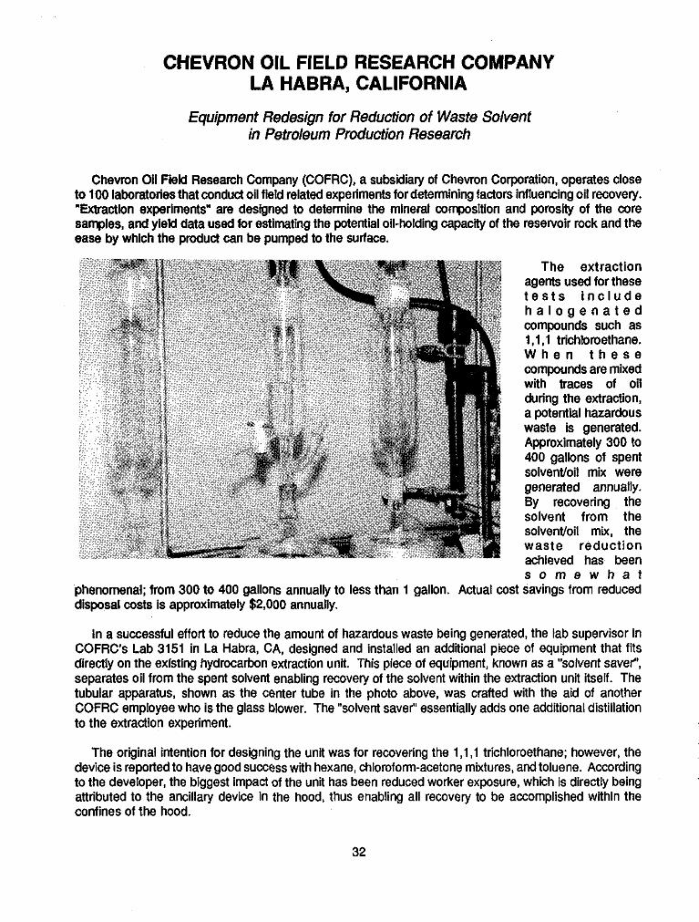
Chevron Oil Field Research Company (COFRC), a subsidiary of Chevron Corporation, operates close to 100 laboratories that conduct oil field related experiments for determining factors influencing oil recovery. "Extraction experiments" are designed to determine the mineral composition and porosity of the core samples, and yield data used for estimating the potential oil-holding capacity of the resewoir rock and the ease by which the produd can be pumped to the surface.
~
The extraction agents used for these t e s t s i n c l u d e h a l o g e n a t e d compounds such as 1, l . l trichloroethane. W h e n t h e s e compounds are mixed with traces of oil during the extraction, a potential hazardous waste is generated. Approximately 300 to 400 gallons of spent solventloil mix were generated annually. By recovering the solvent from the solventloil mix, the waste reduction achieved has been s o m e w h a t
phenomenal; from 300 to 400 gallons annually to less than 1 gallon. Actual cost savings from reduced disposal costs is approximately $2,000 annually.
In a successful effort to reduce the amount of hazardous waste being generated, the lab supervisor in COFRC's Lab 3151 in La Habra, CA, designed and installed an additional piece of equipment that fits directly on the existing hydrocarbon extraction unit. This piece of equipment, known as a "solvent saver"', separates oil from the spent solvent enabling recovery of the solvent within the extraction unit itself. The tubular apparatus, shown as the center tube in the photo above, was crafted with the aid of another COFRC employee who is the glass blower. The "solvent saver" essentially adds one additional distillation to the extraction experiment. __
The original intention for designing the unit was for recovering the 1,1,1 trichloroethane; however, the device is reported to have good success with hexane, chloroform-acetone mixtures, and toluene. According to the developer, the biggest impact of the unit has been reduced worker exposure, which is directly being attributed to the ancillary device in the hood, thus enabling all recovery to be accomplished within the confines of the hood.
~
__
32

Because of the success of the unit, several of the units have been installed in the company's San Ramon, California and Algiers, Louisiana laboratories. A patent application has been filed for the device.
Supplemental to the solvent recovery ongoing at the La Habra COFRC facility is a relatively new computerized chemical inventory used for tracking relevant data for every chemical used throughout COFRC's labs. The automated data base went on-line in November of 1988 and has led to a procedural source reduction technique by reducing unnecessary ordering of chemicals and fully utilizing existing inventories. The system enables researchers to enter an ID number on their desktop computer and retrieve a comprehensive list of all other researchers that have that certain desired chemical onsite. The chemical inventory was expanded in the summer of 1989 and now includes approximately 3,500 chemicals that are keyed to the particular regulatory list(s) in which the chemical appears.
Collection of Recovered Solvent
NOTES: Company Contacts: Bill CampbelVLarry Brooks Chevron Oil Field Research Company 1300 Beach Blvd. La Habra, CA 90631 -6374 (213) 694-7000
References: - Chevron Save Money and Reduce Toxics (SMART) Brochure
Chevron Oil Field Research Company
The photograph at the left shows the 99% plus pure s o l v e n t b e i n g recovered from the "solvent saver" device from within the hood. The r e c o v e r e d solvent is pure enough to be reused i n s u b s e q u e n t e x p e r i m e n t s , whereas, before, it was discarded.
. American Petroleum Institute
33

ATLANTIC RICHFIELD CORPORATION CARSON, CALIFORNIA
Process Modification for Production of Substitute "Emission Control" Fuel for Reduction of Air Pollutants
__ .~ ~
-
Although the state of California has the most stringent regulations in the nation for stationary and mobile -~ sources of air emissions, the air quality in the Los Angeles Basin continues to be the worst in the nation. As a result, state and local authorities have included use of clean-burning non-gasoline motor fuels as a mandate in their plans to address the problems. However, conversion to nongasollne motor fuels will not take place immediately. Currently, approximately 30% of vehicular pollution in Southern CalRmia is generated by vehicles that lack catalytic converters and operate on leaded regular gasoline. These include pre-1975 automobiles and pre-1989 ttucks.
Atlantic Richfield Corporation (ARCO) has developed a cleaner-burning fuel that can be produced by current technology for use in these existing vehicles. The new gasoline, Emission Control - 1 (EC-1) Regular was formulated to reduce carbon monoxide, nitrogen oxide, ozone, and particulate matter to help meet federal and state ambient air qualily standards.
~
Based on the results of exposure and urban airshed models ( to be discussed below), ARC0 projected that If the EC-1 gas formulation replaced all leaded gasoline in Southern CaliRomia, there would be a reduction from 350 to 600 tons per day of vehicular pollutants ( d e p e n d i n g o n misfueling estimates). This would be e q u i v a l e n t t o removing 20% (or 320,000) Of the old vehicles from the roads. Based on
ARCOs market in Southern California, the company estimates that around 100 tons of vehicle pollutant are reduced daily. There are no cost savings associated with production of EC-1. ARCO reports that they spend 24 per gallon more to produce EC-1 regular versus leaded regular.
EC-1 was developed between March and August of 1989 by a team of engineers and chemists at the ARCO Engineering and Technology Center in Anaheim and the ARCO Los Angeles Refinery in Carson. The team utilized its in-house gasoline component interaction model to define candidate fuel blends and then employed the services of an outside firm for urban airshed modeling to screen the candidate fuel
__
-
34

blends for ozone formation potential. The resulting EC-1 formulation contains no lead, but instead contains methyl tertiary butyl ether (MTBE), a high octane component blended to a minimum of 1% oxygen.
The ARCO refinery in Carson, California was chosen as the production faciliiy for the EC-1 formulation, since it supplies the Southern California market which has some of the worst air quality in the nation. To help generate raw chemicals, a new MTBE production facility was constructed at the Carson Refinery at a cost of approximately $20 million (see photo on previous page).
This facility supplies all of the blendstock required for the EC-1 production. Other than constructing the MTBE plant, the changes made at the Carson plant were operational. For instance, to reduce the vapor pressure of the new gasoline (to reduce volatility), ARCO reduced the amount of butane blended into the production process. The excess butane was sold or burned for fuel.
The Carson Refinery began producing EC-I at a rate of 18,000 to 20,000 barrels per day, and the refinery can produce 36 million gallons of EC-1 per month. The new formulation was introduced to the public on September 1, 1989, and is available at over 700 locations that sell gasoline (e.g. mini markets, tune up centers, and sewice centers) between Santa Barbara and San Diego. To implement EC-1, ARCO had to install distinctive dispensers having larger nozzles for leaded gasoline to target the fuel to older vehicles without catalflic converters and other emission control devices.
The newly formulated gasoline was fleet tested at two independent laboratories, the Southwest Research Institute (SWRI) and the National Institute for Petroleum and Energy Research (NIPER). EPA vehicle emission test procedures were strictly adhered to at both laboratories. The fleet consisted of 20 vehicles including 16 passenger cars and 4 light duty trucks. The reported summary of results are shown below.
Summary of Results
Pollutant Reduction %
Hydrocarbons (exhaust) 5 Hydrocarbons (evaporative) 22 Carbon Monoxide (CO) 10 Nitrogen Oxide (NOx) 6 Benzene 43 Toluene 42 Xylenes 52
It should be noted that oxygenated and olefinic emissions were found to be somewhat higher; formaldehyde (+ 17%) and propylene (+ 17%).
Systems Applications, Inc. (SAI) conducted a study for ARCO to analyze the effects of EC-1 emissions in Southern California, and to project the consequent effect of those emission changes on episode ozone levels in the South Coast Air Basin. SAl’s urban airshed model (UAM) analysis for ozone air quality used meteorological condfiions occurring from June 5-7, 1985 as a baseline. This is the same episode emphasized for all ozone modeling done in the development of the ozone portion of the Southern California Air Quality Monitoring Program (SCAQMP). Their acute ozone exposure findings predicted that use of the EC-1 fuel would result in 453,997 fewer person-exceedences of the federal ozone standard. Elimination of on-road non-catalyst (NCAT) emissions was predicted to result in a 28% reduction; which, on an ozone
35
exposure basis, EC-1 was expressed as equivalent to eliminating emissions from 20.5% of on-road NCAT vehicles.
ARCO recently (September 1990) introduced EC-P gasoline for vehicles having catalytic convertors that operate on unleaded fuels. Over the next ten years, the company plans to spend an estimated $2 billion
EC-P fuel, the Carson Plant reactivated a distillation column that had been out of service for several years. This "dehexanizet", shown in the photograph below, removes certain carbon compounds in advance of the catalytic reforming process. The result is a 300 barrels- per-day reduction in benzene production, which, in turn, reduces benzene in the product fuel (EC-P) without increasing benzene in the other gasoline grades. EC-P contains a minimum of 1.5% oxygen in the form of MTBE. The refinery purchases MTBE from an ARCO chemical plant in Houston, Texas to supplement the refinery's production.
__ to convert both regular and premium unleaded gasoline lines into "emission control fuels". To make the .~
-
-~
NOTES: Company Contacts: Doua Elmets. Director/ MeGa 8 Public Relations 1055 W. Seventh St. Lo6 Angeles. CA 90017 (213) 4869181
Mr. Leigh Noda Mgr. of Refinery Technology 1801 East Sepulveda Blvd. Canon, CA 90749-6210 (213) 816-8730
Other: . Winner of Mayot's Award of Excellence for Significant
References: - . EC-1 Emission Control Gasoline - Final Repod. by L. Cohu, L. Ram. and J. %gal (ARCO Products I%.), September 1989. Prevention
Achievement in Pollution
- Analysis of the Effect of a New . New Product Award. First place California Society of Pmlessional ARCO Gasoline (EC-1) On Ozone
Levels in the South Coast Air Basin, Engineers __ by Systems Applications, Inc., September 30, 1989. . Air Pollution Technology Award.
South Coast Air Quality Management District - Product of the Year. Fortune Magazine
__
36

MAOLA MILK AND ICE CREAM COMPANY NEW BERN, NORTH CAROLINA
Reduction of Dairy Waste Via Minimization of Product Loss and Process Changes to Reduce BOD, Load
Maola Milk and Ice Cream Company (Maola) is a multiproduct daily producing several milk products (Le., buttermilk, chocolate imitation milk drink, etc.), frozen desserts, juices, and fruit drinks. By the end of 1987, Maola had fully implemented a milk loss program and had completed several process changes that allowed for the recovery and reuse of ice cream, milk and water.
The initial source reduction measures prevented the loss of an estimated 170,000 Ibs. of milk and decreased the biochemical oxygen demand (BOD,) by 17,000 Ibs. over an approximate 4 month period (Sept. - Dec., 1986). The resulting savings in dollars were estimated at approximately $24,000 per month. When the recovery process changes were included with the milk loss program, the company estimated that it had saved in excess of $350,000 during 1988. As a gauge of how much waste was being reduced at its source, the municipal treatment works which receives Maola's waste discharge, reported "profound results" soon after Maola's efforts were implemented. Influent data to the City of New Bern Treatment Plant showed a 14.7% reduction in BOD, per day and a 22.8% decrease in suspended solids over a one-month period, much of which was attributable to the Maola program. This aided the New Bern Plant in complying with the National Pollutant Discharge Elimination System (NPDES) requirements. Although difficult to quantify, Maola's reduced BOD, load also translated into reduced chemical usage, less sludge accumulation, and reduced power requirements for the New Bern Treatment Plant.
ANIMAL FOOD RECOVERY SYSTEM Check Valve
""d r ,::::::::~:::~::::::. :;. .......... :<. :qyJ .................... ; ........................ ............. A:>:::*:::::::::$: $;?@% E .......
Drain
Source: Carawan et al. 1987
Maola's interest in a planned operation for reducing waste began in 1986 with the formation of a research team, consisting of the c o m p a n y management and North Carolina State University (NCSU) food scientists from the North Carolina Agricultural Extension Service. This project team conducted a feasibility study for reduction of waste l o a d b y t h e recoverylreuse of process waste. The scope of the study included: (1) a plant survey to identifv
sources of milk solids losses from the production processes, (2) identification of methodswhich could be used to reduce or recover and reuse the milk solids lost from the system, (3) development of a conceptual
37
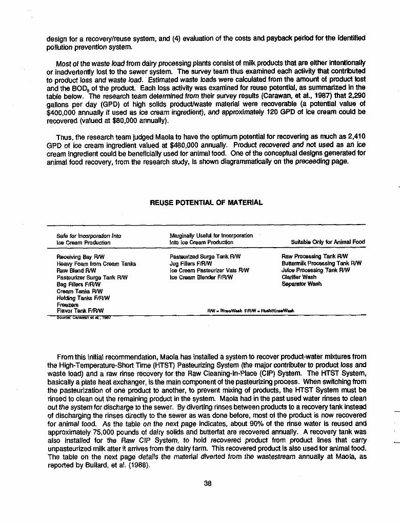
design for a recovery/reuse system, and (4) evaluation of the costs and payback period for the identified pollution prevention system.
Most of the waste load from dairy processing plants consist of milk products that are either intentionally or inadvertently lost to the sewer system. The survey team thus examined each activity that contributed to product loss and waste load. Estimated waste loads were calculated from the amount of product lost and the BOD, of the product. Each loss activity was examined for reuse potential, as summarized In the table below. The research team determined from their survey results (Carawan. et al., 1987) that 2,290 gallons per day (GPD) of high solids producthaste material were recoverable (a potential value of $400,000 annually if used as ice cream ingredient), and approximately 120 GPD of ice cream could be recovered (valued at $80,000 annually).
Thus, the research team judged Maola to have the optimum potential for recovering as much as 2,410 GPD of ice cream ingredient valued at $480,000 annually. Product recovered and not used as an ice cream ingredient could be beneficially used for animal food. One of the conceptual designs generated for animal food recovery, from the research study, is shown diagrammatically on the preceeding page.
__
- ~
REUSE POTENTIAL OF MATERIAL
Safe for Inmrparation Into Marginally Useful for Incorporation Im Cream Production Into Ice Cream Production
Receiving Bay WW Pasteurized Surge Tank WW Heavy Foam from Cream Tanks Jug Fillers FIRMI Raw Blend WW Ice Cream Pasteurizer Vats FUW Pasreuiizer Surge Tank WW Im Cream Blender FIRMI Clarifier Wash Bag Fillers F/WW Separator Wash Cream Tank WW Holding Tank F I W Freezers Flavor Tank F/WW soY1Oo: Liarawsnot*.. lssl
Suitable Only for Animal Food
Raw Promssing Tank W Bunemilk Processing Tank RMI Juiw Pmwssing Tank W
WW - RitwWwh F M - Flu.NRinuNyuh
From this initial recommendation, Maola has installed a system to recover product-water mixtures from the High-Temperature-Short Time (HTST) Pasteurizing System (the major contributer to product loss and waste load) and a raw rinse recovery for the Raw Cleaning-In-Place (CIP) System. The HTST System, basically a plate heat exchanger, is the main component of the pasteurizing process. When switching from the pasteurization of one product to another, to prevent mixing of products, the HTST System must be rinsed to clean out the remaining product in the system. Maola had in the past used water rinses to clean out the system for discharge io the sewer. By diverting rinses between products to a recovery tank instead of discharging the rinses directly to the sewer as was done before, most of the product is now recovered for animal food. As the table on the next page indicates, about 90% of the rinse water is reused and approximately 75,000 pounds of dairy solids and butterfat are recovered annually. A recovery tank was also installed for the Raw CIP System, to hold recovered product from product lines that carry unpasteurized milk after it arrives from the dairy farm. This recovered product is also used for animal food. The table on the next page details the material diverted from !he wastestream annually at Maola, as reported by Bullard, et al. (1988).
-
-
38

MATERIAL DIVERTED FROM THE WASTE STREAM ANNUALLY
Recovered Dairy Material (Ib) Butterfat Solids
HTST Rinse (Reused)
(“A) 1.4 8 (Ib) 939,120 13,148 61,981 ($) 18,802 23,555
Other Reusable Material (“w 3.5 12.5 (Presently Diverted to (Ib) 245,960 8,644 22,136 Animal Feed; Value Shown ($1 12,361 8,412 for Reuse)
Ice Cream Plant (“h) 8 32 (Recovered and Reused (Ib) 117,000 9,360 28,080 Material) ($) 13,385 10,670
Unreusable Waste (“4 0.5 4
(9 0 0 Source: Bullard, et ai, 1988
(Animal Feed) (Ib) 804,960 4,025 28,174
NOTES
Contact: Dr. Roy Carawan N.C. State - Food Science Ext
- Box 7624 Raleiah. NC 27695 (919 j737-2956
Relerences: “A Dairy Processor Does It” R. Bullard, J. Rushing, and 2 “Detailed Plans for the Reduction
In Waste Load from a Daily and Carawan, Proceedings of the ice Cream Plant“, by R. C a k a n , N.C. Pollution Prevention J. Rushing, and R. Bullard, Feb. Program; Waste Reduction 1987. Pollution Prevention: Progress and Prospects Within North Carolina, Raleigh, NC, March 31, 1988.
39

MOUNT DORA GROWERS COOPERATIVE MOUNT DORA, FLORIDA
Reuse of Washwater for a Fresh Citrus Packinghouse
The Mount Dora Growers Cooperative represents 46 citrus growers in central Florida. The Cooperative's packinghouse, which has been a landmark in the city of Mount Dora for almost 75 years, is where oranges, grapefruits, and tangerines are cleaned and prepared for shipment to out-of-state retail outlets.
-
In 1988, the cooperative became concerned with the amount of wastewater it generated. On a typical day, the Cooperative generated 10,000 to 20,000 gallons of wastewater. Wth the assistance of Boyle Engineering Corporation, the Cooperative has installed (December 1990) a water pretreatment and reuse system that enables the packinghouse to reclaim and reuse their water 20 to 40 times over. The resulting daily water savings can exceed as much as 19,000 gallons.
Waste washwater is generated from a number of operations conducted at the packinghouse, including detergent washing, disinfection, waxing, and coloring. The chemicals used in these citrus prep operations are listed on the next page.
The fruit is first disinfected with a chlorinated water spray, and then washed with detergents and wetting agents to remove pesticides, residuals, sooty mold, and dirt. A soluble red color additive is then applied to accentuate an orange color appearance to the actual yellow, yellow-green color of the fruit. The fruit skin is coated with an FDA food grade wax emulsion, primarily to seal the porous skin and lessen any dehydration and help prevent spoilage during shipment. A fungicide is also added to retard spoilage.
The characteristics of the waste water depend on the type of citrus being processed. The water generally contains residuals of cleaning chemicals, wax and oil, sand, sooty mold, and fruit debris (navels and leaves). The strength amount of chemical additives used) of the washwater is dependent on the fruit type, time of season, and the condition of the fruit upon arrival from the groves.
The Cooperative had discharged its washwater to the local city waste water treatment plant (WWTP), but switched to alternative means over concerns about the relative strength of the washwater. Parameters of primary concern to the city are total Kjeldahl nitrogen (TKN), chemical oxygen demand (COD), total suspended solids (TSS), oil and grease, and copper. -
40

TVPICAL CHEMICALS USED AT FRESH CrlRUS PACKINGHOUSES
The Cooperative contracted Boyle Engineering Corporation of Orlando, to evaluate pretreatment options for the Coop's combined washwater flow, which ranged from
The pretreatment option chosen was a coagulation, flocculation, and primary sedimentation system. The pretreatment system, which was started in October of 1988, consisted of three primary components: a 10,000 gallon clarlier (see photo, on preceeding page), a septic tank, and a drain field. The performance, based on the average of five monthly composite samples collected between December 1988 and April 1989, is shown below.
The modiied septic tank system, which serves as an aerobic digester and sludge thickener, receives sludge 2-4 times a day. Supernatant overflows to a drain field; stabilized solids are removed periodically and are applied to a local citius grove owned by the Cooperative.
10,000 - 20,000 gpd.
The reuse system was developed in conjunction with the pretreatment system and created a clean technology that allows reclaimed water to be reused approximately 20-40 times before being replaced. The system includes a 1,100 gallon polypropylene reservoir (see photo, preceeding page), a two HP recirculation pump, a canister filter with a removable micro-mesh cartridge element, and a chlorinator. A flow diagram of the Cooperative's washwater reuse facilities is shown on next page.
The effluent drains by gravity into the reservoir, which provides adequate contact time for chlorination (in accordance with State regulations - Chapter 17-610, F.A.C.). Chlorination also minimizes algae growth in the reuse system. If necessary make-up water is added to the reservoir from the potable water system. A surfactant is used periodically to reduce foaming that is caused by the color-add process for early season oranges.
Four reported benefits of the new pretreatment and reuse system are: 1) water conservation, 2) compliance with water restrictions, 3) use of a viable disposal method and, 4) lower operating costs.
PRETREATMENT PERFORMANCE
Parameter Removal (%I TSS 78 COD b 6 0 BOD 50 TKN 49 TP 63 Copper 61 011 & Grease 60
The capital cost of the pretreatment system was approximately $15,000, and $5,000 for the reuse system. Annual operating cost are approximately $8,000. The plant Cooperative spends less than 1 1/2 hours each day on facility operation.
In the citrus growing areas of Florida, water and sewer charges are currently $2.00 - $5.00 per thousand gallons and are expected to significantly increase in the future. Based on figures accumulated since
41

MOUNT WRA GROWERS COOPERATIVE UASHWATER REUSE FACILITIES
D e t e r g e n t
4 BOXING
I Rrclailned Hater 1-2 mi1 Chlorinm
I DELIVERY
quaternary h " l " m
CRATE b TRUCK PACKINGHOUSE-_, PRETREATMENT , REUSE TRAILER RINSING WASHWATER SYSTEM SYSTEM
I Reclaimed Water
1-2 mgll C h l o r i n e
REUSE STREAM
RESERVOIR ->RECYCLE PUMP---sFILTER------,RECLAIMED WATER
Chlorine ake-up Water u C h l o r i n e k S u r f a c t a n t
Note: Dashed (- -1 lines indicate processes &e. coloration) which are not conducted on late season fruit. Source: Melear and Bouch, 1990.
system start-up, the Cooperative has estimated a reduction of total water usage and sewer disposal Costs from $750/month to $25/month. Although there are added chemical purchase costs of approximately $150/month, the Cooperative estimates that it will recover initial capital costs within 2-3 growing seasons.
NOTES Company Contacts: Robert Blairs. General Mgr. Mount Dora Growers Cooperative
Erik Melear Boyle Engineering Coy.
P.O. Box 36 Mount Dora, FL 32757 (904) 383-41 14
320 E. South St. Orlanda. FL 32801 (407) 425-1 100
Referencas: . "Pretreatment and Reuse of Washwater for Fresh Ciws Packinghouses", by E. Melear and D. Bouch, presented at the Fourth Annual Food lndusby Environmental Conference, Novemberl2-14,1990,Atlanta, GA (sponsored by Georgia Tech Research InstiUte).
-
42

DOW CHEMICAL, U.S.A. HEBRON, OHIO
Source ReductiodRecycling and Reuse of Solid Wastestreams Associated With Production of Polystyrene and Barrier Films
Dow Chemical’s Licking River Film Center, having approximately 130 full time employees, manufactures polystyrene and barrier films used for a variety of applications. TRYCITETM film (produced since 1969) is used as window film in business envelopes, labels for bottles, and lamination on paper plates and cups. SARANEXTM film which is produced by the Barrier Film Department, is used in food and medical packaging as a barrier of odor and moisture. The primary solid wastes associated with the processing and packaging of the film include loose film, off-grade film and process related waste.
Beginning in 1989, the Film Center has reduced landfill disposal by 600,000 pounds per year through process modification, equipment redesigns, and improved quality control. Source reduction applications have been implemented at the Film Center in conjunction with recycling efforts. Installation of state-of-the- art winder technology has resulted in computer-controlled tension and consistent roll quality. As a result, roll scrap is being reduced by 200,000 pounds per year. Installation of proprietary equipment to control polymer degrading through the process has additionally reduced scrap and has extended process runs.
By reprocessing customer-returned film and off grade film, and resale of film trim, the Barrier Film Department has reduced landfill disposal costs and total operating costs by $500,000 per year. The Polystyrene Department has saved an estimated 75,000 pounds per year in landfill volume from the recycle of resin and film, and an estimated addilional 40,000 pounds per year by recycling polystyrene dust.
Also, the plant has reduced water usage by 3 million gallons a year by reducing single-pass cooling water usage. Cooling water which is needed to cool extruded molten recycled polymer (before the material can be made into pellets), is now recycled for the plants two largest streams that require cooling. Facility
Source: Dow Chemical, Hebron, OH
43

employees have refined the existing cooling bath system to eliminate single-pass iuns. Cooling water, that was previously discharged to the sewer after one cooling pass is now recooled in heat exchangers and reused. Other non-process-specific wastes recycled include scrap aluminum, steel, copper, cardboard, and in-house paper (estimated at 90% recycle).
across their product line to one involving specific recycling practices for specific product lines. To determine what waste streams within the plant could be targeted for recycling, a waste reduction team was formed and consisted of production engineers, operating technicians and purchasing personnel. The first task the team engaged in was the development of a process flow chart listing all raw materials, internal and extemal recycle streams, and all discarded process and packaging material. A flow chart showing the revised management approach for the Polystyrene Film Department is shown on the preceeding page.
After careful evaluation and research into available markets, the following materials were selected for
__
Waste reduction management was changed at the Film Center in 1990, from a generic recycle program ~~
-
~
recycle consideration: cardboard; loose film, cut as samples for evaluation of film quality: po styrene dust and resin from processing of film;
scrap film and pallets from Lickin 8 ier Film Center's customers: and palets Y and end boards used in ship ing film rolls;
spent cooling water used to cool a 'Im pmduction material.
It was determined that the loose film and scrap customer film could be recycled by the use of grinding equipment as long as p l a n t q u a l i t y specifications were met (see photo at left).
Recovery of loose film is accomplished on-line and off-line. The photograph on the next page shows one type of off-line film trim recovery s y s t e m , w h i c h includes an unwind stand and a cyclone separator.
The polystyrene dust and resin that do not meet plant quality specifications, are now sold to companies that can use the material in other polystyrene products that do not require high grade clarity (i.e. polystyrene furniture).
Ongoing at the Licking River Film Center is a "Quantifying Waste Program". To fully implement this
estimated to be the end of the first quarter of 1991). Also, the center plans to monitor and quantify waste- streams as related to waste of air, solid waste, hydraulic load, and non-aqueous liquid waste.
__
program, it is planned to designate onsite compactors to a specific category of solid waste (completion is -
44

Off-Llne Recovery System Source: Dow Chemical
NOTES Other: Company Contacts: References: - DOW WRAP Program - 1989 Marvin Schmehl. Safeiy and Training
Director a Fred Houdeshen, WRAP OH Outstanding Achievement Award Winner Coordinating Technician . Waste Reduction Always
Pays (WRAP) Sheet Licking River Film Center 3700 Hebmn Road Hebron. Ohio 43025 (614) 929-5100
. Dow Chemical, U.S.A. - Hebron,
45
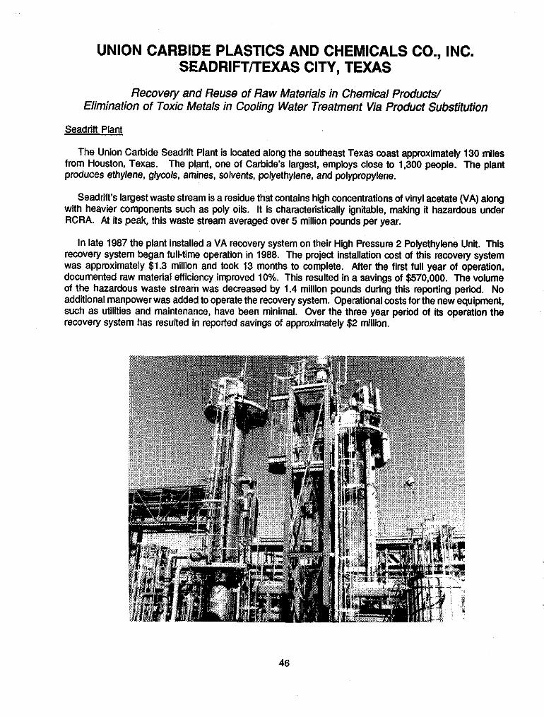
UNION CARBIDE PLASTICS AND CHEMICALS CO., INC. SEADRlFTflEXAS CITY, TEXAS
Recovery and Reuse of Raw Materials in Chemical Products/ Elimination of Toxic Metals in Cooling Water Treatment Via Product Substitution
__ ~
Seadrifl Plant
The Union Carbide Seadrift Plant is located along the southeast Texas coast approximately 130 miles from Houston, Texas. The plant, one of Carbide's largest, employs close to 1,300 people. The plant produces ethylene, glycols, amines, solvents, polyethylene, and polypropylene.
Seadrift's largest waste stream is a residue that contains high concentrations of vinyl acetate (VA) along with heavier components such as poly oils. It is characteristically ignitable, making it hazardous under RCRA. At its peak, this waste stream averaged over 5 million pounds per year.
In late 1987 the plant installed a VA recovery system on their High Pressure 2 Polyethylene Unit. This recovery system began full-time operation in 1988. The project installation cost of this recovery system was approximately $1.3 million and took 13 months to complete. After the first full year of operation, documented raw material efficiency improved 10%. This resulted in a savings of $570,000. The volume of the hazardous waste stream was decreased by 1.4 million pounds during this reporling period. No additional manpower was added to operate the recovery system. Operational costs for the new equipment, such as utilities and maintenance, have been minimal. Over the three year period of its operation the recovery sysiem has resulted in reported savings of approximately $2 million.
~
46

The vinyl acetate recovery system (photograph on previous page) is closed-loop recycle (see flow diagram on next page). The residue is taken from the reaction system purge column and various entrainment separators to the Recovery System ("Lights" Column Feed Tank), which operates at fairly low pressures and temperatures below 100' C. in the feed tank some of the dissolved lights (ethylene and propylene) are sent to a vent gas suction system. An inhibitor is also added at this point to prevent the VA from polymerizing.
The residue stream is then fed to the Lights Column where the bulk of the dissolved ethylene and propylene are taken out. This column contains a number of trays with an integral upward draft condenser. The column operates under 20 psi and below 100" C.
The lights from the Lights Column go to the Flash Tank for disposal via thermal treatment and the heavies (vinyl acetate and poly oils) go to the Vinyl Acetate (VA) Recovery Column. The VA Recovery Column contains 21 trays below 20 psi and below 150' C. The column takes refined VA as an "overhead make at a reflux ratio of approximately 2. The recovered vinyl acetate is therefore able to be used as a raw material in the original process.
Improvements were made to the recovery system during 1989 which resulted in another 10% increase in efficiency. The calandria was revised to provide better fluid dynamics and heat transfer. Modifications to recycle piping improved recovery during start-up, shutdown, and reactor upsets. Closer attention to product scheduling and operating parameters (such as base temperature) have also allowed for improvements with no additional capital investment. The control panel display has been modfied to show operators the cost savings in a graphic way to encourage optimization.
Texas City Plant
Union Carbide Chemical and Plastics facilities at Texas City, Texas is situated on approximately 120 acres. There are approximately 1500 employees at the location. The principal products produced here are C&, alcohols, aldehydes, and acids, vinyl acetate, and vinyl chloride monomers. The plant, which has been in operation since 1941 also serves as a major redistribution point for many other products.
At this plant, chromates had been the preferred corrosion inhibitor in water treatment applications because of cost and effectiveness. However, in April of 1988, the Energy Systems Department made a switch in the treatment of the cooling water cycle that eliminated chromates and zinc from the plant waste water stream. The switch was made to comply with stricter regulations placed on chromatic discharges by OSHA and EPA and implemented by the Texas Air Control Board and the Texas Water Commission.
Initially, the corrosion rate of the new system was higher than expected. Adjustments were made in the treatment program and the corrosion rates dropped to an acceptable level. As a result of the change to the phosphate treatment program the plants discharge of chromates to the waste water system was reduced to zero.
A stabilized phosphate treatment program by Betz Chemicals, Dianodic 11, was chosen after several water treatment programs were investigated. It's cost is about 2.6 times that of the chromate treatment. Akhough this was not the lowest cost program investigated, it was chosen based on its effectiveness, ease of implementation, and because phosphates are non-regulated chemicals. The switch in the treatment of the cooling water cycle that eliminated chromates and zinc from the plant waste water stream was made in April 1988.
The cooling water cycle is comprised of 11 cooling towers of various sizes and loads that contain approximately 13 million gallons of water. The average blowdown rate of the cycle is 600 gallons per million (gpm). The conversion was accomplished by allowing the chromates to drop from a normal level
47

r, L l l h D + reed From Rmctlo" wrtsn -".I
n (01- bW"WY
* SYSt6.
T-d Talk
21 o . ~ n t i n g c ~ ~ d i t i o n . i vary with Because the phosphate treatment program requires tighter control of the svstem DH and phosphate
Re.ctor Product SlMPLIFIED FLOW DIAGRAM VINYL ACETATE RECOVERY SYSTEM 3) w a r wtmnt on17 I S 1 1 1 u , t m t t d
~
The phosphates slug feeds to 3 towers. The stabilized phosphate treatment requires that the pH of the cycle be maintained between 7.2 and
t R m ,,nli Fsed 7.8. The make up water (Brazos River water) is normally about 8.0 pH, therefore sulfuric acid has to be added to control the pH in the required
___ ~~ "l",l *.Ut.
S W W W
,a "<""I Lcet l t r
B.<X ro m t m -
Dlul
~
Source: Union Carbide, Seadrift Plant concentration, chemicai feed and monitoring systems (BMAC 1300)
were installed at two cooling towers. Output from the BMACs is transmitted by phone lines to personal computers in a central control room for data monloring and tracking.
To monitor the effectiveness of the conversion, a test heat exchanger was installed throughout the cycle. Plant personnel were able to track and control the heat load on the exchanger and visually inspect the tubes for corrosion. Corrosion coupons were installed throughout the cycle. The coupons provided a numerical value and visual indication of corrosion. Corrosion meters were installed at three cooling towers and measured instantaneous corrosion rates. Although not absolute the readings were used as data. Numerous inspections of various plant heat exchangers were performed as production units were down for maintenance.
NOTES Company Contacts and Referenma:
Seadritl Plant Seadritl Plant Kamy Hunt Mike Gohlke Sr. Environmental Engr. Envr. Protection Dept. HP-2 Unit P.O. Box 186 (512) 553-2949 Port Lavaca, TX 77979 (512) 553-3054
Sr. Production Engr.
Texas City Plant Corporate Stan Green, Plant Mgr. Solvent 8 Coatings Div. Energy Systems Dept. Environmental Affairs Texas City, TX 77592- 39 Old Ridgebury Rd. 0471 Danburf. CT 06817-
Henty Ward Health, Safety and
(409) 948-5514 0001 (203) 794-5270
48
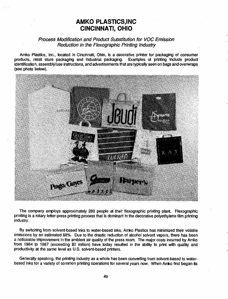
AMKO PLASTICS,INC CINCINNATI, OHIO
Process Modification and Product Substitution for VOC Emission Reduction in the Flexographic Printing Industry
Amko Plastics, Inc., located in Cincinnati, Ohio, is a decorative printer for packaging of consumer products, retail store packaging and industrial packaging. Examples of printing include product identification, assemblyhse instructions, and advertisements that are typically seen on bags and overwraps (see photo below).
The company employs approximately 280 people at their flexographic printing plant. Flexographic printing is a rotary letter-press printing process that is dominant in the decorative polyethylene film printing industry.
By switching from solvent-based inks to water-based inks, Amko Plastics has minimized their volatile emissions by an estimated 88%. Due to the drastic reduction of alcohol solvent vapors, there has been a noticeable improvement in the ambient air quality of the press room. The major costs incurred by Amko from 1984 to 1987 (exceeding $2 million) have today resulted in the ability to print with quality and productivity at the same level as U.S. solvent-based printers.
Generally speaking, the printing industry as a whole has been converting from solvent-based to water- based inks for a variety of common printing operations for several years now. When Amko first began its
49

program however, attempts to do the same for flexographic printing had resulted in lktle success. Amko Plastics’ conversion to water-based inks has recently attained a level of success that was envisioned as far back as 1983 when the firm first experimented with water-based inks. From 1984 through mid-1987. Amko experimented with newly, in-house developed technologies and techniques (many of which are proprietary), which initially adversely affected their manufacturing operations. The photo below shows a 6-color impression flexographic printing press designed and specified for printing plastic films exclusively with water-based inks.
___ . ~~
For years, alcohol solvent inks have persisted as the preferred inks for printing polyethylene films for the following reasons:
- Alcohol achieves uniform wetting of the polyethylene surface, which prevents streaking, pin holing and variegated color which diminishes visual quality of the product.
Alcohol dries rapidly after being applied to the substrate. In flexographic printing, inadequate drying adversely affects the finished print quality and slows production.
The resin in the inks that carries and binds pigment and other ink additives to the substrate is readily resoluble in alcohol. Poor resolubility of ink solids also diminishes print quality and increases downtime required for press wash-up.
__
Although water-based inks for printing on low-density, polyethylene films were not available in 1983, Amko chose to pursue the ink-switch alternative over alcohol recovery or installation of incinerator control devices, based on a detailed cost analysis. Not until latter 1987 did Amko make a complete conversion to new flexographic print technologies that emerged for use on a commercial production scale. Amko
__
50

experimented with proprietary ink formulations. Following the decision to switch to a water-based acrylic ink, additional experimental process changes and modifications were evaluated. Some of these included the following:
Control of H of the water-based ink to maintain ink viscosity and print quality, a variable not critical
Modification of dryer heads between successive color print stations which directed heated air onto printed film. To enable the increased drying capability needed for drying water-based inks, Amko had to determine changes to air volume on and away from the printed film, specific air velocity as the air impinges the film, and the proper amount of heat in the air.
Redesign of their ink metering systems for handling a higher stren th ink that was needed to achieve
reduced drying times (the previously used alcohol inks were applied in thicker layers, but still dried quickly due to their volatility).
Determination of the optimum shape and number of cells that were needed for the anilox rolls to achieve quality and productive printing. The anilox rolls transfer ink from the ink fountain transfer roll to the printing plate. As water-based ink formulation continued lo be improved, Amko replaced its metal anilox rolls, which were having their wear-life drastically reduced as the use of water-based ink increased, with more expensive ceramic rolls which last longer and offset initial cost increases.
A witch in the fountain roll surface material to harder durometer rubber to improve wear-life of the roll. The new ceramic rolls had an increased wearing effect on the fountain rolls.
Development of systems and equipment to inversely vary the percentage of resin "slip additive" blended into the resin as the film was being extruded. Controlling the erucamid slip additive content was essential for high speed printing with water-based inks, so that the blooming of this slip additive on the surface of the plastic ("slip blooming") could be reduced. The more slip that blooms on the surface, the more difficult it is for the water-based ink to adhere to the plastic print media.
Installation of newer and larger corona treating systems that enabled the electrostatic treatment of the film surface at the higher surface tension required for water-based inks.
A switch to foam cushion "sticky-back" from conventional "sticky-back'' to compensate for the additional pressure needed to achieve the greater amount of impression, required by water-based inks, for uniform film welting and transfer. Sticky-back secures the printing plate to the cylinder in the press.
to alcohol- E ased inks.
a reduction in the amount of liquid in water ink that would in turn a 9 low for thinner ink application and
Having reduced substantially their VOC's emission, the company is now in the process of designing a recovery system that will virtually eliminate the costly disposal of the plant's ink press wastes. This system, which is expected to be on-line in early 1991, will enable processing of ink solids for disposal as a non- hazardous waste and will also enable the treated wastewater effluent to be discharged directly to the sanitary sewer system. The payback for the recovery system is expected to be one year.
NOTES: Company Contact: Geome A. Makrauer. PresGent and CEO ' Amko Plastics, Inc. 12025 Tricon Road Cincinnati, OH 45246-1792 (513) 671-1777
References: "Innovations of Flexographic Printing: Reducina VoCs with Water-Lased Inkshhen Printing on High-Slip Polyethylene Films", by George A. Makrauer. Pre- sented at the 80th Annual Meeting of APCA, New 'fork. NY, June 21-26, 1987.
- Amko Plastics Inc.
51

TERRY PRINTING, INC. JANESVILLE, WISCONSIN
Reduction of VOC Emissions Via Product Substitution and Recycling of Solid Waste in the Commercial Sheef-Fed Printing Industry
__ . ~~
-
Terry Printing, Inc. is afamily-owned, full-sewice, commercial sheet-fed printer that produces instruction manuals, sales sheets, catalogs, brochures, annual reports, and greeting cards. The fifty year old company employs 38 people.
In I989 Terry Printing replaced their petroleum-based inks with an ink derived from soy beans. The new ink is used for all of the company's printing operations and has not required any conversions of equipment for incorporation (Le., fivecolor press shown below).
Although Terry Printing has not conducted monitoring of emissions, the soy-based ink manufacturer has reported that the ink reduces volatile emissions into the air by 65- 85%. In addition to changing to soy-based ink, Terry Printing implemented a major paper recycling effort in 1989. To date, an estimated 80% reduction of paper and related solid wastes has been achieved. Measures to recover silver film negatives have resulted in resale of 6- 10 ounces of silver every six to eight months.
-
Terry Printing first became familiar with soy-based inks from a Wisconsin advertising firm that works closely with agribusiness clients. The advertising firm was curious about soy-based inks and requested the printing company to contact Sinclair & Vatentine, a developer of soy heat-set inks for magazines and glossy paper printing. The developer first received a request for developing a sheet-fed, soy-based ink in late 1988, and extensive lab work conducted in 1989 resulted in the development of a soy ink with drytime, gloss and tub characteristics reported to be comparable to most conventional sheet-fed systems.
The major concern of replacing petroleum-based printing inks with the soy-based ink centered around the drying time of the ink. Unlike newspaper inks, which dry by absorption and evaporation, sheet-fed inks dry by oxidation. To solve this problem, the ink supplier had to develop a proprietary formulation of soy ink, petroleum oil, and dryers. To date, Terry Printing, the first sheet-fed printing company who pioneered (according to their supplier) the use of soy-based inks in Wisconsin, has not incurred any problems with delayed ink drying.
Soy ink was originally developed by the American Newspaper Publishers Association in 1985 as a buffer against oil crises. The ink is made from refined soybean oil, which is the same product as vegetable cooking oils. Much of the soy-based ink success has been measured in lithographic and letterpress
-
__
52
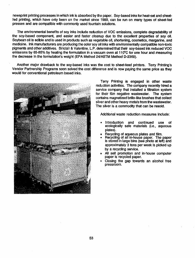
newsprint printing processes in which ink is absorbed by the paper. Soy-based inks for heat-set and sheet- fed printing, which have only been on the market since 1989, can be run on many types of sheet-fed presses and are compatible with commonly used fountain solutions.
The environmental benefiis of soy inks include reduction of VOC emissions, complete degradabilty of the soy-based component, and easier and faster cleanup due to the excellent properties of soy oil. Soybean oil is edible and is used in products such as vegetable oil. shortening, cosmetics, margarine, and medicine. Ink manufacturers are producing the color soy oil inks with environmentally compatible non-toxic pigments and other additives. Sinclair & Valentine, L.P. determined that their soy-based ink reduced VOC emissions by 6585% by heating the formulation in a vacuum oven at 110°C for one hour and measuring the decrease in the formulation’s weight (EPA Method 24/ASTM Method D-2369).
Another major drawback to the soy-based inks was the cost to sheet-feed printers. Terry Printing’s Vendor Partnership Programs soon solved the cost difference and is now paying the same price as they would for conventional petroleum based inks.
Terly Printing is engaged in other waste reduction activities. The company recently hired a service company that installed a filtration system for their film negative wastewater. The system contains magnetized brillo-like brushes that collect silver and other heavy metals from the wastewater. The silver is a commodity that can be resold.
Additional waste reduction measures include:
Introduction and continued use of ecologically safe materials (i.e., aqueous plates). Recycling of a ueous plates and film. Recycling of a! in-house pa er The paper
approximately 3 tons per week is picked up by a recycling service. All self promotion and in-house computer paper is recycled paper. Closing the gap towards an alcohol free pressroom.
is stored in large bins (see p R ’ oto at left) and
53
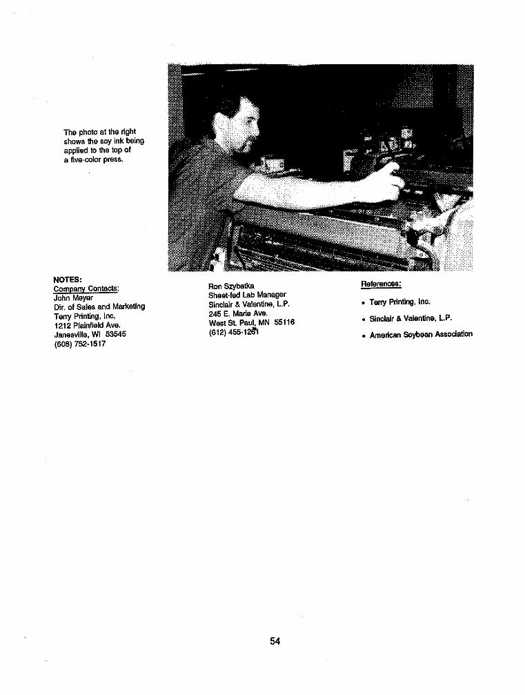
The photo at the right shows the soy ink baing applied to the top Of a five-wlor press.
NOTES: Companv Contacts: John Meyer Dir. of Sales and Marketing Teny Printing, Inc. 121 2 Plainfield Ave. Janesville, WI 53545 (608) 752-1517
Ron Szybalka Sheet-fad Lab Manager Sinclair &Valentine, L.P. 245 E. Mane Ave. WestSt. Paul, MN 55116 (612) 455-1261
References:
. Teny Printing, InC. . Sinclair &Valentine. L.P. . American Saybean Association
54

KENWORTH TRUCK COMPANY CHILLICOTHE, OHIO
Reduction in Paint Waste Via Process Changes and Equipment Modification
The Kenworth Truck Company is a Division of PACCAR, Inc. The Kenworth Division consists of two plants in the U.S., one in the State of Washington, and a facility in Chillicothe, Ohio. The Kenworth- Chillicothe plant was built in 1973 and began production in 1974 at a low rate. The Chillicothe plant is located on a 121-acre parcel of land, and current production rate at the facility is several times higher than the original start-up rate. The plant employs over 850 people.
Kenworth produces class 8 trucks and specializes in custom paint colors and designs. This facility assembles live different models. The production processes are primarily related to assembly and painting while the majority of the components of the vehicles are manufactured at other sites.
Kenworth Truck C o m p a n y h a s achieved a significant decrease in overall volume 01 waste generated per truck and associated d i s p o s a l a n d transportation costs f r o m i m p r o v e d housekeeping source reduction measures. These amounts are shown in the table at the rigM and take into account increased truck production between 1987 and 1989. As a result of t h e i r e f f o r t s , Kenworth’s waste disposal cost per truck was reduced by over 77% from 1987 to 1989.
1987 88 vs 87 89 vs 88
TNck Produdion Base Year +32.1% +11.8%
Wane Paint 8 Still Bottoms Pounds Generated _.. +6.6% +29.3% Disposal Costs _.. -30.9% -74.0%
DetadGiied Paint Pounds Generated ... -27.9% -46.2% Disposal Cons ... -24.1% -41.0%
Pretreatment Sludge Pounds Generated ... -15.1% +24.2% Disposal Costs ... +57.3% -30.5%
Heavy Drums Pounds Generaled ... -73.3% -100.0% Disposal Costs ... -77.4% -100.0% -
Source: Kenworth Truck Co.
Production is done on one main assembly line which begins with the chassis (frame rails) and ends with a ready-to-start truck. Associated assembly/finishing procedures such as cab painting, door assembly, phosphating of small parts, etc., are done on small assembly lines which incorporate their finished work in the main assembly line. The assembly line is continuously moving and a tight schedule is required to produce the required quantities in one 8-hour period.
A large portion of the wastes associated with truck manufacturing center around the painting operations. Kenworth converted from conventional solvent paints to high solid paints on all trucks in 1989. This
55
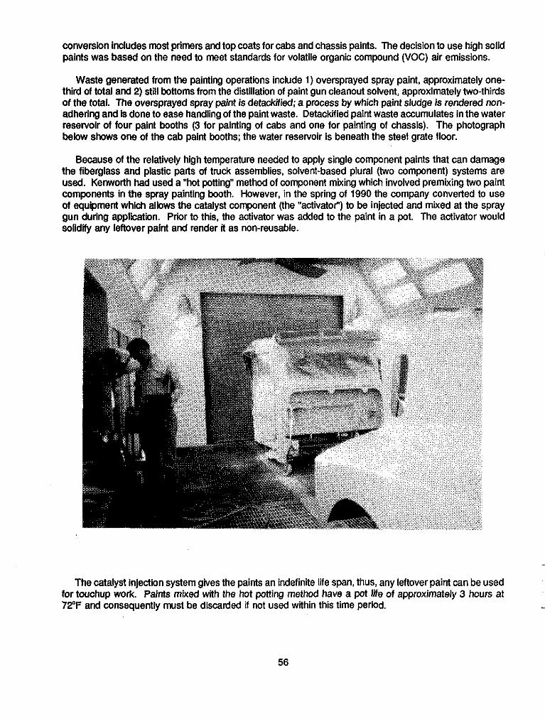
conversion includes most primers and top coats for cabs and chassis paints. The decision to use high solid paints was based on the need to meet standards for volatile organic compound (VOC) air emissions.
Waste generated from the painting operations include 1) oversprayed spray paint, approximately one- third of total and 2) still bottoms from the distillation of paint gun cleanout solvent, approximately two-thirds
adhering and is done to ease handling of the paint waste. Detackfied paint waste accumulates in the water
below shows one of the cab paint booths; the water reservoir is beneath the steel grate floor.
Because of the relatively high temperature needed to apply single component paints that can damage the fiberglass and plastic parts of truck assemblies, solvent-based plural (two component) systems are used. Kenworth had used a "hot potting" method of component mixing which involved premixing two paint components in the spray painting booth. However, in the spring of 1990 the company converted to use of equipment which allows the catalyst component (the "activator") to be injected and mixed at the spray gun during application. Prior to this, the activator was added to the paint in a pot. The activator would solidify any leftover paint and render it as non-reusable.
___ of the total. The oversprayed spray paint is detackiied; a process by which paint sludge is rendered non-
reselvoir of four paint booths (3 for painting of cabs and one for painting of chassis). The photograph
.~
-
~
The catalyst injection system gives the paints an indefinite life span, thus, any leftover paint can be used for touchup work. Paints mixed with the hot potting method have a pot Me of approximately 3 hours at 72OF and consequently must be discarded if not used within this time period.
56

In addition to switching to the catalyst injection system, Kenworth converted their paint spray guns in the chassis booth to high volume-low pressure guns. Listed below were specific measures taken related to this effort to minimize generation of waste paint.
Ftting the air regulators with locks to prevent operators from using a higher pressure, thus minimizing overspray.
9 Installing new air caps to reduce painting pressures from 60 psi to 40 psi.
Heating of paints to reduce their viscosity to allow use of lower air pressures (chassis paint is heated to 95" to 100°F and most cab paints are heated to 110°F).
Improved efficiency of the solvent that cleans out the spray guns by injecting the solvent via air at 60 psi. This reduces the volume of solvent required.
NOTES: Company Contact: Ken Legner, Environ. Engr. Kenworth Truck Co. 65 Kenworth Drive Chillicothe, OH 45601 (614) 774-5227
References: "Haz Waste Reduction Using . "Waste Minimization Op ortuniiy Assessment: A Class S !ruck
Oganic Polymers', by D. Mitchell and M.Schweers, Pollution
Assembly Plant", Draft Report by Engineering. March 1989. Science Applications lntemetional corp.. 1990. Kenwarth Truck Company
57

SOUTHERN CALIFORNIA EDISON COMPANY ROSEMEAD, CALIFORNIA
Elimination of Tailpipe Emissions and Reduction of Waste Oil Via Incorporation of Electric Powered Vehicles in Fleet Transportation
Southern California Edison Company (Edison) provides electric power to over 4 million customers in a 50,000 square mile area of southern California. The company has more than 7,000 vehicles.
In the fall of 1989, Edison purchased 15 electrically- powered vans (EVs) and initiated a loan program (utilizing 9 of the vehicles) for interested fleets. In less than a year‘s time, over 50 private and public fleets have borrowed the vehicles for a period of 3 weeks. Edison is planning on as many as 15 EVs in its own fleet in 1991. These EVs will replace existing gasoline vehicles (e.g., mail delivery vans, site shuttle buses, etc.). Edison’s power plants have the capability to easily sustain over a half million EVs.
M E ELECTRIC 6-VAN
Battery Pack Controller
FRONT OF
VEHICLE
Charging Plug
Source: SCE Co.
The South Coast Air Quality Management District (SCAQMD) and the Southern California Association of Governments adopted a 20-year airquality management plan in 1989 to help the City of Los Angeles meet federal and state air quality standards. The plan’s goal is to have 40% of the new passenger vehicles purchased by the year 2000 to be low-pollution-emitting vehicles. Edison estimates that initial incorporation of the 15 EVs will reduce fleet vehicle NO, emissions by 384 Ibdyr, VOC emissions by 322 Ibs/yr and CO emissions by 3,708 Ibs/yr. These figures are based on each vehicle being driven an average of 50 miles per day, 250 days a year. However, emission reduction potential has a much greater significance as increased numbers of electric vehicles are incorporated into its fleet.
The EV utilized by Edison is called the G-Van, which is manufactured cooperatively by General Motors, Vehma International Inc. and Chloride EV Systems (a battery and electronics manufacturer). This one-ton cargo/passenger van was designed for versatile use (e.g. carrying heavy cargo, van pooling, shuttle services, etc.) and is reported to be an improved version of the Griffin Van, aforerunner of the G-Van which is currently being
used in England. A schematic of the electric G-Van and a(3hoto of its charging plugs are shown above.
58

The GVan has the following power sources:
Power Source Function
DC Electric Motor Main Power Main and Auxiliary Power (i.e., lights, wipers, etc.) Operation of hydraulic pump (for power
brakeskteering) Auxiliary Power (115 minute reserve) - Recharge of lead-acid battery
Auxiliary Battery Li uid fueled Heater diesel) O!-biard Charger (260-250 V, 35 Amps, 60 Hz) Heat in winter
The G-Van has a range of approximately 60 miles under simulated urban driving, and has a top speed of 52 m.p.h. Market research has indicated that about 60,000 of the 150,000 commercial fleet, light-duty vehicles (about 40%) in Southem California travel fewer than 60 miles per day.
The Electric Power Research Institute (EPRI) conducted a study comparing the emission characteristics of EVs (including the G-Van) with gasoline vans of the same type. According to EPRI, all emissions associated with EVs come from the power plants that would supply the electricity, with the emission characteristics dependent on the generation mix of fuels (i.e., coal, petroleum, etc.) used to generate the electricity.
There are several direct and indirect sources of emissions associated with electrical energy production, including mining operations, fuel transportation, and electricity transmission and distribution. EPRI used all generation scenarios in their study, which ranges from fossil-fueled power plants to future cleaner power plants.
The principal emiss ions tha t contribute to u&an air quality problems are VOCs, NO, and carbon monoxide. VOCs and nitrogen oxides are precursors of ozone. The table at right compares California and U.S. 1 9 8 9 e m i s s i o n s t a n d a r d s f o r gasoline-powered vans to EV emissions under d i f ferent generation scenarios.
Fleet Van Emissions Associated with Urban Air Quality (grams per mile)
GM Gasoline-Powered Van Electric G-Van
Current Emissions Generation Scenarios
LA Basin us. US. New California U.S. Current Current Post-1995
vocs 0.8 1.1 0.02 0.02 0.02
NO. 1.1 1.8 0.17 2.5 0.7 co 9.0 10.0 0.02 0.1 0.1
Source: EPRI Technical B r i e f (1989)
EPRI concluded that widespread EV use could contribute only minimally to inareased power plant emissions of SO2 and NOx.
The two primary capital costs associated with EVs are: (1) initial purchase of the vehicle and (2) battery replacement. The G-Van's current higher initial cost is reported to be partially offset by an increased vehicle life. Battery life is 4 years or 27,000 to 30,000 miles. Maintenance on the G-Van consists mainly
59

of filling the lead-acid battery pack with water every three weeks. The vehicle requires approximately 8 hours of charging daily via a 220 volt, 50 amp wall socket.
c Fuel and Maintenance Cost Comparison , (over l i f e o f vehicle) I I G-Van 1 I I Fuel and Maintenance Costs
6) 0 Fuel
Maintenance
Source: Southern Cal i forn ia Edison Co.
NOTES: Companv Contact: William R. West Senior Environmental Specialist Southern California Edison Co. P.O. Box 800
An added benefit of the EVs is the reduction in waste oil generated. Based on Edison’s normal servicing of their gasoline driven vans, EVs would result in an annual waste oil reduction - ~~
per van of approximately 5 gallons. As reported by Edison, there are considerable fuel and maintenance cost savings associated with this alternate vehicle technology, as shown graphically at the left.
__
~
References:
. EPRl Technical Brief
Southern California Edison Co. 2244 Walnut Grove Ave. Rosemead, CA 91770 (818) 302-9534
60
*US. GOVERNMENT PRINTING OFFICE: I993 - 750002/60173