Embed Size (px)
Citation preview

www.unicourse.org Unit Workbook 1 – Level 4 EEE – U63 Electrical Power – LO1 Three-Phase Systems author: Michael Lopez BEng(Hons) MSc PGCert CertEd MIFL MIET FHEA ©Unicourse Ltd 2016
Page 1 of 15 Page 1 of 15
online learning
Pearson BTEC Higher Nationals in Electrical and Electronic Engineering (QCF)
Unit 63: Electrical Power
Unit Workbook 1 in a series of 2 for this unit
Learning Outcome
Three-Phase Systems

www.unicourse.org Unit Workbook 1 – Level 4 EEE – U63 Electrical Power – LO1 Three-Phase Systems author: Michael Lopez BEng(Hons) MSc PGCert CertEd MIFL MIET FHEA ©Unicourse Ltd 2016
Page 2 of 15 Page 2 of 15
Contents INTRODUCTION .................................................................................................................................................. 3
GUIDANCE .......................................................................................................................................................... 3
1.1 Use of j Notation ..................................................................................................................................... 4
1.2 Three-Phase Circuit Problems using j Notation ...................................................................................... 8

www.unicourse.org Unit Workbook 1 – Level 4 EEE – U63 Electrical Power – LO1 Three-Phase Systems author: Michael Lopez BEng(Hons) MSc PGCert CertEd MIFL MIET FHEA ©Unicourse Ltd 2016
Page 3 of 15 Page 3 of 15
Purpose
Theory
Question
Challenge
ee
Example
Video
INTRODUCTION This Workbook guides you through the learning outcomes related to:
Use of j Notation
GUIDANCE This document is prepared to break the unit material down into bite size chunks. You will see the learning
outcomes above treated in their own sections. Therein you will encounter the following structures;
Explains why you need to study the current section of material. Quite often learners
are put off by material which does not initially seem to be relevant to a topic or
profession. Once you understand the importance of new learning or theory you will
embrace the concepts more readily.
Conveys new material to you in a straightforward fashion. To support the treatments
in this section you are strongly advised to follow the given hyperlinks, which may be
useful documents or applications on the web.
The examples/worked examples are presented in a knowledge-building order. Make
sure you follow them all through. If you are feeling confident then you might like to
treat an example as a question, in which case cover it up and have a go yourself.
Many of the examples given resemble assignment questions which will come your
way, so follow them through diligently.
Questions should not be avoided if you are determined to learn. Please do take the
time to tackle each of the given questions, in the order in which they are presented.
The order is important, as further knowledge and confidence is built upon previous
knowledge and confidence. As an Online Learner it is important that the answers to
questions are immediately available to you. You will find the answers, upside down,
below each set of questions. Contact your Unit Tutor if you need help.
You can really cement your new knowledge by undertaking the challenges. A
challenge could be to download software and perform an exercise. An alternative
challenge might involve a practical activity or other form of research.
Videos on the web can be very useful supplements to your distance learning efforts.
Wherever an online video(s) will help you then it will be hyperlinked at the
appropriate point.

www.unicourse.org Unit Workbook 1 – Level 4 EEE – U63 Electrical Power – LO1 Three-Phase Systems author: Michael Lopez BEng(Hons) MSc PGCert CertEd MIFL MIET FHEA ©Unicourse Ltd 2016
Page 4 of 15 Page 4 of 15
1.1 Use of j Notation
When we have circuits containing just resistors then life is so easy in terms of circuit analysis. Most useful
circuits also contain capacitors and inductors (usually coils and windings). The introduction of capacitors
and inductors into circuits causes ‘phase angles’ in our calculations. The study of these phase angles is
made much easier by introducing complex numbers.
From your level 3 studies you will have come across Inductive Reactance (XL) and Capacitive Reactance (XC).
These terms are used to quantify the amount of ‘opposition’ caused by capacitors and inductors to changes
in current or voltage. The term ‘reactance’ is brought about because capacitors cannot be charged or
discharged in zero time, and inductors cannot be energised or de-energised in zero time. A good analogy
for capacitors is the amount of water in a bathtub. It is impossible to fill a bathtub in zero time, and it’s also
impossible to empty a bathtub in zero time. The amount of reactance from capacitors and inductors is a
function of their manufactured properties and the frequency of operation. Let’s review the equations for
these reactances…
𝑋𝐿 = 2𝜋𝑓𝐿 [Ω]
𝑋𝐶 =1
2𝜋𝑓𝐶 [Ω]
where;
𝑋𝐿 = 𝑖𝑛𝑑𝑢𝑐𝑡𝑖𝑣𝑒 𝑟𝑒𝑎𝑐𝑡𝑎𝑛𝑐𝑒 (𝑚𝑒𝑎𝑠𝑢𝑟𝑒𝑑 𝑖𝑛 𝑂ℎ𝑚𝑠, Ω)
𝑋𝐶 = 𝑐𝑎𝑝𝑎𝑐𝑖𝑡𝑖𝑣𝑒 𝑟𝑒𝑎𝑐𝑡𝑎𝑛𝑐𝑒 (𝑚𝑒𝑎𝑠𝑢𝑟𝑒𝑑 𝑖𝑛 𝑂ℎ𝑚𝑠, Ω)
𝑓 = 𝑓𝑟𝑒𝑞𝑢𝑒𝑛𝑐𝑦 (𝑚𝑒𝑎𝑠𝑢𝑟𝑒𝑑 𝑖𝑛 𝐻𝑒𝑟𝑡𝑧, 𝐻𝑧)
𝐿 = 𝑖𝑛𝑑𝑢𝑐𝑡𝑎𝑛𝑐𝑒 (𝑚𝑒𝑎𝑠𝑢𝑟𝑒𝑑 𝑖𝑛 𝐻𝑒𝑛𝑟𝑖𝑒𝑠, H)
𝐶 = 𝑐𝑎𝑝𝑎𝑐𝑖𝑡𝑎𝑛𝑐𝑒 (𝑚𝑒𝑎𝑠𝑢𝑟𝑒𝑑 𝑖𝑛 𝐹𝑎𝑟𝑎𝑑𝑠, 𝐹)
Consider the RLC circuit below…
We can draw a phasor diagram for this circuit, as follows…

www.unicourse.org Unit Workbook 1 – Level 4 EEE – U63 Electrical Power – LO1 Three-Phase Systems author: Michael Lopez BEng(Hons) MSc PGCert CertEd MIFL MIET FHEA ©Unicourse Ltd 2016
Page 5 of 15 Page 5 of 15
The black arrow represents resistance. The current through a resistor is always in phase with the voltage
across it. We place resistance on the horizontal axis.
The red arrow represents inductive reactance. We see that this leads the resistance by 90 degrees
(𝜋 2 𝑟𝑎𝑑𝑠.⁄ ). We name this axis the ‘+j axis’. Mathematicians tend to designate this the ‘+i’ (imaginary) axis.
Engineers do not use i since it clashes with the current symbol, so we use ‘j’ instead.
The blue arrow represents capacitive reactance. We see that this lags the resistance by 90 degrees
(𝜋 2 𝑟𝑎𝑑𝑠.⁄ ). We designate this the ‘-j’ axis.
The dashed lines represent a graphical method of finding the resultant of these phasors, drawn in green.
We term this resultant the impedance of the circuit and mark it with ‘r’ for resultant. This resultant
impedance makes an angle with the horizontal axis, marked with 𝜙.
The resultant impedance is given the symbol Z for calculation purposes. We see that the green resultant
has both horizontal and vertical components. The horizontal contribution is known as the real component
and the vertical contribution is known as the imaginary component.
We may use Pythagoras’ theorem to denote impedance as follows…
𝑍2 = 𝑅2 + 𝑋2
∴ 𝑍 = √𝑅2 + 𝑋2 [Ω]
In complex number notation we represent Z as…
𝒁 = 𝑹 + 𝒋(𝑿𝑳 − 𝑿𝑪) [𝛀]

www.unicourse.org Unit Workbook 1 – Level 4 EEE – U63 Electrical Power – LO1 Three-Phase Systems author: Michael Lopez BEng(Hons) MSc PGCert CertEd MIFL MIET FHEA ©Unicourse Ltd 2016
Page 6 of 15 Page 6 of 15
Worked Example 1
Worked Example 2
The series combination of a 𝟏𝟎𝟎𝛀 resistor and a 10mH inductor form an impedance. If the circuit
frequency is 10kHz determine the impedance of the circuit in complex number form.
We have the real part already. It is 100Ω (the value of the resistor). We calculate the imaginary part of the
circuit as follows…
𝑋𝐿 = 2𝜋𝑓𝐿 = 2𝜋 × 104 × 10 × 10−3 = 628.3Ω
We denote a complex number as follows…
𝒄𝒐𝒎𝒑𝒍𝒆𝒙 𝒏𝒖𝒎𝒃𝒆𝒓 = 𝒓𝒆𝒂𝒍 𝒑𝒂𝒓𝒕 + 𝒋(𝒊𝒎𝒂𝒈𝒊𝒏𝒂𝒓𝒚 𝒑𝒂𝒓𝒕)
So we may answer the question by writing…
𝒁 = (𝟏𝟎𝟎 + 𝒋𝟔𝟐𝟖. 𝟑) [𝛀]
If a complex number is given by 𝒁 = (𝟏𝟎𝟎 + 𝒋𝟔𝟐𝟖. 𝟑) [𝛀] find its Polar Form.
The Polar Form is given by the length of the resultant impedance (represented by r and the green phasor
above) and the associated angle (𝜙) of the resultant impedance, as follows…
𝑍 = 𝑟∠𝜙 [Ω]
Basic trigonometry tells us that…
𝑟 = √𝑅2 + 𝑋𝐿2 = √1002 + 628.32 = 636.2 Ω
𝜙 = 𝑡𝑎𝑛−1 {𝑋𝐿
𝑅} = 𝑡𝑎𝑛−1 {
628.3
100} = 80.96𝑜
So the Polar Form is given by…
𝒁 = 𝟔𝟑𝟔. 𝟐 ∠𝟖𝟎. 𝟗𝟔𝒐 [𝛀]
Quite often we need to add, subtract, multiply and divide complex numbers. We may also like to multiply
and divide Polar numbers. Let’s look at the mechanics of these operations.
We define j as the square root of -1…
𝑗 = √−1

www.unicourse.org Unit Workbook 1 – Level 4 EEE – U63 Electrical Power – LO1 Three-Phase Systems author: Michael Lopez BEng(Hons) MSc PGCert CertEd MIFL MIET FHEA ©Unicourse Ltd 2016
Page 7 of 15 Page 7 of 15
Worked Example 3
Worked Example 4
𝑗 + 𝑗 = 2𝑗
5𝑗 − 3𝑗 = 2𝑗
𝑗 × 𝑗 = 𝑗2 = √−1 × √−1 = −10.5 × −10.5 = −10.5+0.5 = −11 = −1
6𝑗
3𝑗= 2
A circuit current calculation involves the division of a voltage by an impedance…
𝒊 =𝟏𝟎 − 𝒋𝟑𝟎
𝟑 + 𝒋𝟒
Determine the value of the current.
To perform such calculations we need to determine the complex conjugate of the denominator and then
multiply this complex conjugate by both the numerator and denominator. The process is…
𝑐𝑜𝑚𝑝𝑙𝑒𝑥 𝑛𝑢𝑚𝑏𝑒𝑟 1
𝑐𝑜𝑚𝑝𝑙𝑒𝑥 𝑛𝑢𝑚𝑏𝑒𝑟 2=
𝑐𝑜𝑚𝑝𝑙𝑒𝑥 𝑛𝑢𝑚𝑏𝑒𝑟 1
𝑐𝑜𝑚𝑝𝑙𝑒𝑥 𝑛𝑢𝑚𝑏𝑒𝑟 2×
𝑐𝑜𝑚𝑝𝑙𝑒𝑥 𝑐𝑜𝑛𝑗𝑢𝑔𝑎𝑡𝑒 𝑜𝑓 𝑛𝑢𝑚𝑏𝑒𝑟 2
𝑐𝑜𝑚𝑝𝑙𝑒𝑥 𝑐𝑜𝑛𝑗𝑢𝑔𝑎𝑡𝑒 𝑜𝑓 𝑛𝑢𝑚𝑏𝑒𝑟 2
The use of the complex conjugate actually simplifies our task because the new denominator becomes a
purely real number.
The complex conjugate of a complex number is simply the same complex number with the sign on the j
term negated. So, we can write…
𝒊 =𝟏𝟎 − 𝒋𝟑𝟎
𝟑 + 𝒋𝟒=
(𝟏𝟎 − 𝒋𝟑𝟎)
(𝟑 + 𝒋𝟒)×
(𝟑 − 𝒋𝟒)
(𝟑 − 𝒋𝟒)
=30 − 𝑗40 − 𝑗90 − −𝑗2120
9 − 𝑗12 + 𝑗12 + −𝑗216
We know that 𝑗2 = −1 so we may now say…
=30 − 𝑗40 − 𝑗90 − −(−1) × 120
9 − 𝑗12 + 𝑗12 + −(−1) × 16=
30 − 𝑗40 − 𝑗90 − 120
9 − 𝑗12 + 𝑗12 + 16=
−90 − 𝑗130
25
= (−𝟑. 𝟔 − 𝒋𝟓. 𝟐) [𝑨]
Such calculations are rather messy, as you can see. Fortunately, using the Polar Form of complex numbers
when performing divisions leads to shorter calculations.

www.unicourse.org Unit Workbook 1 – Level 4 EEE – U63 Electrical Power – LO1 Three-Phase Systems author: Michael Lopez BEng(Hons) MSc PGCert CertEd MIFL MIET FHEA ©Unicourse Ltd 2016
Page 8 of 15 Page 8 of 15
Worked Example 5
A circuit current calculation involves the division of a voltage by an impedance…
𝒊 =𝟏𝟐 − 𝒋𝟏𝟎
𝟔 − 𝒋𝟗
Determine the value of the current using the Polar Form.
A quick conversion on a scientific calculator will transform our problem into…
𝑖 =15.62∠−39.8𝑜
10.82∠−56.31𝑜 [𝐴]
When faced with such a Polar division the answer is determined in a quite straightforward manner…
Polar Division: Divide the magnitudes, subtract the angles…
𝒊 =𝟏𝟓. 𝟔𝟐∠−𝟑𝟗. 𝟖𝒐
𝟏𝟎. 𝟖𝟐∠−𝟓𝟔. 𝟑𝟏𝒐=
𝟏𝟓. 𝟔𝟐
𝟏𝟎. 𝟖𝟐∠(−𝟑𝟗. 𝟖 − −𝟓𝟔. 𝟑𝟏) = 𝟏. 𝟒𝟒∠𝟏𝟔. 𝟓𝟏𝒐 [𝑨]
Another common task is to multiply the Polar form of two complex numbers, as illustrated in the next
worked example.
A circuit voltage is determined by multiplying current times impedance. The calculation is…
𝑽 = 𝟏𝟎∠𝟒𝟎𝒐 × 𝟑∠𝟓𝟎𝒐 𝒗𝒐𝒍𝒕𝒔
Determine the voltage in Polar form.
When faced with such a Polar multiplication the answer is again determined in a quite straightforward
manner…
Polar Multiplication: Multiply the magnitudes, add the angles…
𝑽 = 𝟏𝟎∠𝟒𝟎𝒐 × 𝟑∠𝟓𝟎𝒐 = 𝟑𝟎∠𝟗𝟎𝟎 𝒗𝒐𝒍𝒕𝒔
1.2 Three-Phase Circuit Problems using j Notation
We are now armed with the mathematical tools needed to analyse three-phase circuits. Consider the
unbalanced 4-wire star system below…

www.unicourse.org Unit Workbook 1 – Level 4 EEE – U63 Electrical Power – LO1 Three-Phase Systems author: Michael Lopez BEng(Hons) MSc PGCert CertEd MIFL MIET FHEA ©Unicourse Ltd 2016
Page 9 of 15 Page 9 of 15
We notice that phase voltage 1 is entirely across phase impedance 1. We may therefore say…
𝑖1 =𝑉1
𝑍1=
230∠0𝑜
115∠100= 2∠−10𝑜 [𝐴]
The situation is similar for the other two phases…
𝑖2 =𝑉2
𝑍2=
230∠120𝑜
5∠−600= 46∠180𝑜 [𝐴]
𝑖3 =𝑉3
𝑍3=
230∠240𝑜
10∠400= 23∠200𝑜 [𝐴]
The sum of these three phase currents is equal to the neutral current (𝐼𝑁) in this star configuration.
Unfortunately, we cannot add Polar quantities (division and multiplication are ok though, as we’ve seen) so
we need to convert each of them into 𝑎 + 𝑗𝑏 form. Some quick conversions on the calculator yield…
𝑖1 =𝑉1
𝑍1=
230∠0𝑜
115∠100= 2∠−10𝑜 ≡ 1.97 − 𝑗0.35 [𝐴]
𝑖2 =𝑉2
𝑍2=
230∠120𝑜
5∠−600= 46∠180𝑜 ≡ −46 + 𝑗0 [𝐴]
𝑖3 =𝑉3
𝑍3=
230∠240𝑜
10∠400= 23∠200𝑜 ≡ −21.61 − 𝑗7.87 [𝐴]
Adding the complex numbers gives…
𝒊𝑵 = (𝟏. 𝟗𝟕 − 𝟒𝟔 − 𝟐𝟏. 𝟔𝟏) + 𝒋(−𝟎. 𝟑𝟓 + 𝟎 − 𝟕. 𝟖𝟕) = −𝟔𝟓. 𝟔𝟒 − 𝒋𝟖. 𝟐𝟐 ≡ 𝟔𝟔. 𝟏𝟓∠−𝟏𝟕𝟐. 𝟖𝟔𝒐 [𝑨]
Let us now consider the voltage between two separate phases. Look at the phasor diagram below…

www.unicourse.org Unit Workbook 1 – Level 4 EEE – U63 Electrical Power – LO1 Three-Phase Systems author: Michael Lopez BEng(Hons) MSc PGCert CertEd MIFL MIET FHEA ©Unicourse Ltd 2016
Page 10 of 15 Page 10 of 15
The diagram on the left illustrates phase 1 in red (𝑉𝑃1). For the sake of analytical simplicity it is given a
magnitude of 1 volt, although this could be scaled up to any voltage you like. The solid blue phasor
represents phase 2, which is 120 degrees out of phase with phase 1. To work out the difference in voltage
between these two phases we must find invert phase 2, giving −𝑉𝑃2, shown dashed in blue. Our task is to
find the resultant of 𝑉𝑃1 and −𝑉𝑃2. This task is performed in the diagram on the right.
The green phasor represents the resultant line voltage, 𝑉𝐿. This is formed by drawing a parallelogram based
upon 𝑉𝑃1 and −𝑉𝑃2. To work out the magnitude of the line voltage in green we apply Pythagoras’
theorem…
|𝑉𝐿| = √[(1 + 0.5)2 + (√3
2)
2
]
|𝑽𝑳| = √[(𝟑
𝟐)
𝟐
+ (√𝟑
𝟐)
𝟐
] = √𝟗
𝟒+
𝟑
𝟒= √
𝟏𝟐
𝟒= √𝟑 𝒗𝒐𝒍𝒕𝒔
This then proves that the line voltage (from phase to phase) is √3 times the phase voltage. Therefore, if we
have a phase voltage of 230 V then the line voltage will be √3 × 230 = 398.37 𝑣𝑜𝑙𝑡𝑠. This figure tends to
be rounded to 400 V in the UK since it is impossible to maintain an exact voltage on the distribution
system.
In the UK the consumer supply voltage is 230 V +10%/-6%. This means that the phase voltage can rise to
253V and fall to 216.2 V. If we look at the line voltage then it can be as high as 438.2 volts and as low as

www.unicourse.org Unit Workbook 1 – Level 4 EEE – U63 Electrical Power – LO1 Three-Phase Systems author: Michael Lopez BEng(Hons) MSc PGCert CertEd MIFL MIET FHEA ©Unicourse Ltd 2016
Page 11 of 15 Page 11 of 15
Worked Example 6
374.5 volts. The figure of 438.2 volts for maximum line voltage tends to be rounded to 440 volts for normal
everyday use and signage.
Three identical coils, each of resistance 𝟐𝟎𝛀 and inductance 𝟐𝟎𝟎𝒎𝑯, are connected in a Delta
configuration to a 230 volt, 50Hz 3-phase supply. Determine the magnitude of each load current.
The first step here is to determine the load impedance on each phase…
𝑋𝐿 = 2𝜋𝑓𝐿 = 2𝜋 × 50 × 0.2 = 20𝜋 = 62.83Ω
∴ 𝑍𝐿 = 20 + 𝑗62.83 ≡ 65.94∠72.34𝑜 [Ω]
The circuit is shown below.
We already know that the line voltage magnitude is √3 times the phase voltage…
𝐿𝑖𝑛𝑒 𝑣𝑜𝑙𝑡𝑎𝑔𝑒 𝑚𝑎𝑔𝑛𝑖𝑡𝑢𝑑𝑒 = √3 × 230 = 398.37 𝑉
We also notice that each load impedance has a line voltage connected. We simply need to divide our
magnitudes for voltage and impedance to find the magnitude of each load current…
𝑴𝒂𝒈𝒏𝒊𝒕𝒖𝒅𝒆 𝒐𝒇 𝒆𝒂𝒄𝒉 𝒍𝒐𝒂𝒅 𝒄𝒖𝒓𝒓𝒆𝒏𝒕 = 𝟑𝟗𝟖. 𝟑𝟕
𝟔𝟓. 𝟗𝟒= 𝟔. 𝟎𝟒 𝑨
There are two common ways to measure the total effective power dissipated in the loads. The two-
wattmeter method is employed for balanced loads. The three-wattmeter method is employed for balanced
or unbalanced loads.

www.unicourse.org Unit Workbook 1 – Level 4 EEE – U63 Electrical Power – LO1 Three-Phase Systems author: Michael Lopez BEng(Hons) MSc PGCert CertEd MIFL MIET FHEA ©Unicourse Ltd 2016
Page 12 of 15 Page 12 of 15
Video
Worked Example 7
Draw a star-star 230V, 50Hz, 3-phase system with BALANCED loads of 𝟐𝟎∠𝟑𝟎𝒐 [Ω] on the TINA-TI
simulator. Use both the two-wattmeter and three-wattmeter methods to determine the total effective
power dissipated in the load system.
Useful starter video on TINA-TI
The TINA-TI free simulator is available here. Before we draw the two measurement circuits we need to
know how to represent a load impedance of 20∠30𝑜 [Ω] at 50Hz.
Convert the Polar form of the given impedance into its complex number form using a calculator…
20∠300 ≡ 17.32 + 𝑗10
We see that the j part is positive so we are looking for an inductor. To determine the value of the inductor
we proceed as follows…
𝑋𝐿 = 2𝜋𝑓𝐿 = 10 ∴ 𝐿 =𝑋𝐿
2𝜋𝑓=
10
2𝜋 × 50= 0.032 𝐻
So each load consists of a resistor of 17.32Ω and a series inductor of 0.032 H. We then place these into our
star load and construct the measurement circuits. The simulation is started by clicking ANALYSIS->AC
ANALYSIS->CALCULATE NODAL VOLTAGES…

www.unicourse.org Unit Workbook 1 – Level 4 EEE – U63 Electrical Power – LO1 Three-Phase Systems author: Michael Lopez BEng(Hons) MSc PGCert CertEd MIFL MIET FHEA ©Unicourse Ltd 2016
Page 13 of 15 Page 13 of 15
Worked Example 8
Challenge
ee
The total power is found in each case by adding the readings on the wattmeters. The two-wattmeter
measurement produces 1.14kW + 2.29kW = 3.43kW. The three-wattmeter method produces three lots of
1.14kW = 3.42kW. There is only a minor difference here, caused by our truncation whilst calculating the
inductance value.
Reproduce the above results on the TINA-TI simulator.
We turn now to the situation where there are faults in our three-phase systems. Consider the system
below which has the first phase open-circuited…

www.unicourse.org Unit Workbook 1 – Level 4 EEE – U63 Electrical Power – LO1 Three-Phase Systems author: Michael Lopez BEng(Hons) MSc PGCert CertEd MIFL MIET FHEA ©Unicourse Ltd 2016
Page 14 of 15 Page 14 of 15
Worked Example 9
Challenge
ee
Here we can see that the neutral current will comprise of 𝑖2 + 𝑖3. Let’s do the calculation…
𝑖𝑁 = 𝑖2 + 𝑖3 =𝑉2
𝑍2+
𝑉3
𝑍3=
230∠120𝑜
5∠−60𝑜+
230∠240𝑜
10∠400= 46∠180𝑜 + 23∠200𝑜
Since we cannot directly add Polar numbers we must convert to complex number form, do the addition,
then convert back to Polar form…
(−46 + 𝑗0) + (−21.61 − 𝑗7.87) = −67.61 − 𝑗7.87 ≡ 68.1∠−173.40 [𝐴]
Note: When you see a load impedance with a negative angle then the reactive component involved is a
capacitance rather than an inductance. This is handy to know when you are checking your calculations
on the TINA-TI simulator.
Reproduce the above results on the TINA-TI simulator.
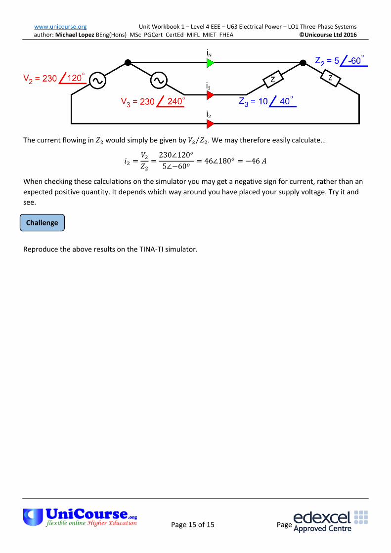
What about the situation where we have impedance 1 developing an open circuit? In this case we would
like to determine the current flowing in impedance 2. Let’s look at the scenario again…
www.unicourse.org Unit Workbook 1 – Level 4 EEE – U63 Electrical Power – LO1 Three-Phase Systems author: Michael Lopez BEng(Hons) MSc PGCert CertEd MIFL MIET FHEA ©Unicourse Ltd 2016
Page 15 of 15 Page 15 of 15
Challenge
ee
The current flowing in 𝑍2 would simply be given by 𝑉2 𝑍2⁄ . We may therefore easily calculate…
𝑖2 =𝑉2
𝑍2=
230∠120𝑜
5∠−60𝑜= 46∠180𝑜 = −46 𝐴
When checking these calculations on the simulator you may get a negative sign for current, rather than an
expected positive quantity. It depends which way around you have placed your supply voltage. Try it and
see.
Reproduce the above results on the TINA-TI simulator.


![[WAABSHKI-MIIGWAN PHASE 1 WORKBOOK] - ltbbodawa-nsn.gov Court/DrugCourt/WMDCP PHASE ONE WORKBOO… · week 1 - where am i? where will i go? 3 week 2 - what to expect from us? what](https://img.pdfslide.us/doc/110x75/5dd090e9d6be591ccb619c4a/waabshki-miigwan-phase-1-workbook-ltbbodawa-nsn-courtdrugcourtwmdcp-phase.jpg)

![[WAABSHKI-MIIGWAN PHASE 2 WORKBOOK] - … Court/DrugCourt/WMDCP PHASE TWO...Song” on DVD#4 and answer the following questions. 1. Did you enjoy “Step 3”, ... [WAABSHKI-MIIGWAN](https://img.pdfslide.us/doc/110x75/5b1885d67f8b9a41258bded7/waabshki-miigwan-phase-2-workbook-courtdrugcourtwmdcp-phase-twosong.jpg)

![[WAABSHKI-MIIGWAN PHASE 2 WORKBOOK]ltbbodawa-nsn.gov/Tribal Court/DrugCourt/WMDCP PHASE TWO... · 2019-05-29 · [WAABSHKI-MIIGWAN PHASE 2 WORKBOOK] January 10, 2011 Little Traverse](https://img.pdfslide.us/doc/110x75/5f30b781dc16ff3a0f1564b7/waabshki-miigwan-phase-2-workbookltbbodawa-nsngovtribal-courtdrugcourtwmdcp.jpg)


![[WAABSHKI-MIIGWAN PHASE 1 WORKBOOK] Court... · [WAABSHKI-MIIGWAN PHASE 1 WORKBOOK] Thank you for joining us in the Waabshki-Miigwan Drug Court Program! Phase One is the Learning](https://img.pdfslide.us/doc/110x75/5e520a5531ec89132931a889/waabshki-miigwan-phase-1-workbook-court-waabshki-miigwan-phase-1-workbook.jpg)