Embed Size (px)
Citation preview
UNIT-V
OPTICAL NETWORKS
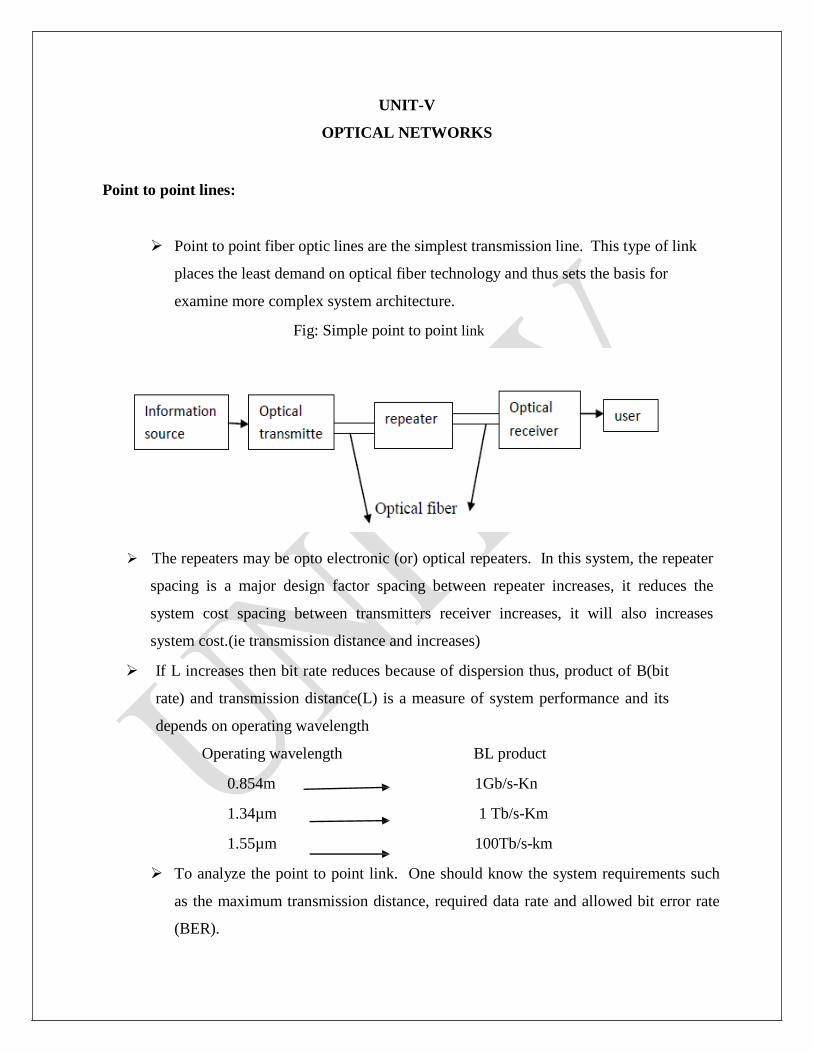
Point to point lines:
Point to point fiber optic lines are the simplest transmission line. This type of link
places the least demand on optical fiber technology and thus sets the basis for
examine more complex system architecture.
Fig: Simple point to point link
The repeaters may be opto electronic (or) optical repeaters. In this system, the repeater
spacing is a major design factor spacing between repeater increases, it reduces the
system cost spacing between transmitters receiver increases, it will also increases
system cost.(ie transmission distance and increases)
If L increases then bit rate reduces because of dispersion thus, product of B(bit
rate) and transmission distance(L) is a measure of system performance and its
depends on operating wavelength
Operating wavelength BL product
0.854m 1Gb/s-Kn
1.34µm 1 Tb/s-Km
1.55µm 100Tb/s-km
To analyze the point to point link. One should know the system requirements such
as the maximum transmission distance, required data rate and allowed bit error rate
(BER).

To satisfy these requirements the system should be designed based on the
components available and their characteristics.
1. Multimode (or) single mode fiber (transmission media)
(a)Core radius (b) fiber repactive index profile (c) bandwidth (or) dispession
(d) fiber attenuation (e) numerical aperture
2. Optical sources (LED or laser diode)
(a) Emission wavelength (b) output power (c) spectral line width (d)
radiation pattern (e) radiating area (f) no. of emitted modes (g)
stability and life time.
3. Light detectors (PIN (or) APD)
(a) Responsivity (b) efficiency (c) operating wavelength (d) speed (e)
sensitivity (f)noise figure
System considerations:
a. Operating wavelength selection:
First generation optical wavelength are in the range of 0.8µm to 0.9µm. Here the
transmission less is maximum and dispersion is also maximum.
Today we choose the wavelength around 1.3µm to 1.55µm. Here the attenuation and
dispersion are very small in silica fibers are used for long distance transmission.
b. System performance:
System performance is decided by three major blocks (or) the optical fiber
transmission. They are transmitter, optical fiber links and receiver. The designer
should choose proper light source, proper optical fiber and proper photo detector to get
high bit rate and high S/N ratio.
Regarding optical fiber, the single mode step index fiber is the proper choice. Even in
that to reduce dispersion proper choice of the refractive index profile is necessary. These
single mode step index fibers are preferable.
Regarding optical sources, single mode laser diodes are suitable for single mode stop
index fibers. For multi mode fibers, heterojunction LEDs chosen based on economy.
Regarding optical receivers, the P-i-n photodiodes and avalanche photodiodes are
preperable. Here also they should be quantum noise limited.

The maximum transmission distance is limited by the net less of fiber cable such that
L=10/α log10(Pt/pr)
α=not loss (in dB/1cm)
Pt=average power from transmitter
Pr=average power detected at receiver =NphvB
Np=minimum no. of photons/bit required
Hv=energy of photon
B=bit rate Link Power Budget:
The main aim of power budget is to have enough power at the receiver so as to maintain
reliable performance during the life time of the entire fiber optic system. The minimum
power required at the receiver is the receiver sensitivity Pmin. The average power
launched at the transmitter is Ptr.
Generally less can be calculated by
Loss(dB)=10log (Pout/pin)
Where Pin and pout =optical power emerging in and out of the element
Let Ptr=transmit power
Pmin=minimum power required at the receiver(decides receiver sensitivity)
Ploss=Total power loss produced by the fiber optic channel
Psm=system margin
Fig: optical power loss model for point to point links
System margin is the link power margin which is normally added with the total
power less in the analysis of power budget
where αfL=fiber attenuation (dB/Km)
Lc =connector loss.
lsp=splicing loss
Total power loss
PT=Ptr-Pmin
Subs (2) in (3)
Therefore, PT= αfL+ lc+lsp +system margin (Psm ) for simplicity add connector loss and
splicing loss
ie lc=lsp
Usually system margin is 6 to 8 dB
Rise budget:
In linear system, the rise time is defined as the time during which the response increases
From 10% to 90% of the final output value when the input is changed abruptly in a stop
wise manner.
τr = rise time
τf=fall time
Rise time budget analysis is a method for determining the dispersion limitation of an

optical fiber link. The rise time of the system is given by
∆ti= Rise time of each component in the system
There are four basis element that limit the system spped of optical communication
system.
1. Transmitter rise time
2. Receiver rise time
3. Material dispession rise time
4. Modal dispession rise time
1. Transmission rise time (ttx):
It depends on light source, drive circuit of light source. It is the calculated value and it
is specified optical fiber data sheet.
2. Receiver rise time (trx):
It depends on photodetector response and receiver front and response . Receiver front
and response depends on first order low pass filter in the receiver having step response and it
is given by
u(t)=step frequency
Brx=3dB Bandwidth of receiver
The rise time of the receiver is defined as the time interval between g(t)=0.1 to
g(t)=0.9. This is known as 10 to 90% rise time. It is generally given by
Trx=350/ Brx (or) 350/B B= Brx
3. Material dispession rise time:
σλ=half of spectral width of the source
D=dispession parameter (Its value change from fiber
to fiber) L=Length of the optical fiber
4. Modal dispession rise time:
The relationship between B.W and rise time of the fiber is given by
∆t modal =0.44/BM(L)
BM(L)=Bandwidth BM in a link length L can be expressed by approximate emphrical relation as,
BM(L)=Bo/Lq
Where Bo=B.W of 1Km length of fiber cable
Q=empirically fit parameter
Q=1 indicates steady state modal equilibrium is not reached
Q=0.5 indicates steady state modal equilibrium is reached
∆t modal=0.44/ Bo/Lq = 0.44Lq/Bo
Total rise time of optical system is given by
Where all time ∆t sys is in nano seconds
SONET: (Synchronous Optical Network)
SONET is the set of standards developed by Bell core and then adopted by 170-
7(cc 177) as an international standard designated Synchronous Digital Hierarchy
(SDH).
SONET specifies the rates, formats and parameters of all physical transmission media.
Even though SONET is called an optical network, it can support traditional electrical
transmission. The electrical signal in SONET are called Synchronous Transport
Signal(STS).STS level 1,designated as STS-1 transmit at 51.84 Mbits/sec. All other
levels are multiples of STS-1 as shown in the following table.
Electrical signal Optical signal Bit rate STS-1 OC-1 51.84
STS-3 OC-3 155.52
STS-9 OC-9 466.56 STS-12 OC-12 633.08
STS-18 OC-18 933.12 STS-24 OC-24 1244.16
STS-48 OC-48 2488.32
Higher bit rate signals, starting with STS-9 are not defined as electrical standards
and they never actually transmitted in electrical form
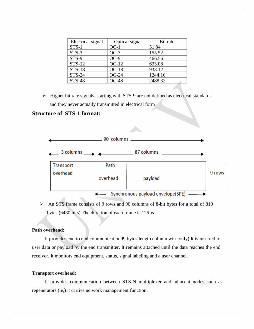
Structure of STS-1 format:
An STS frame consists of 9 rows and 90 columns of 8-bit bytes for a total of 810
bytes (6480 bits).The duration of each frame is 125µs.
Path overhead:
It provides end to end communication99 bytes length column wise only).It is inserted to
user data or payload by the end transmitter. It remains attached until the data reaches the end
receiver. It monitors end equipment, status, signal labeling and a user channel.
Transport overhead:
It provides communication between STS-N multiplexer and adjacent nodes such as
regenerators (ie,) it carries network management function.
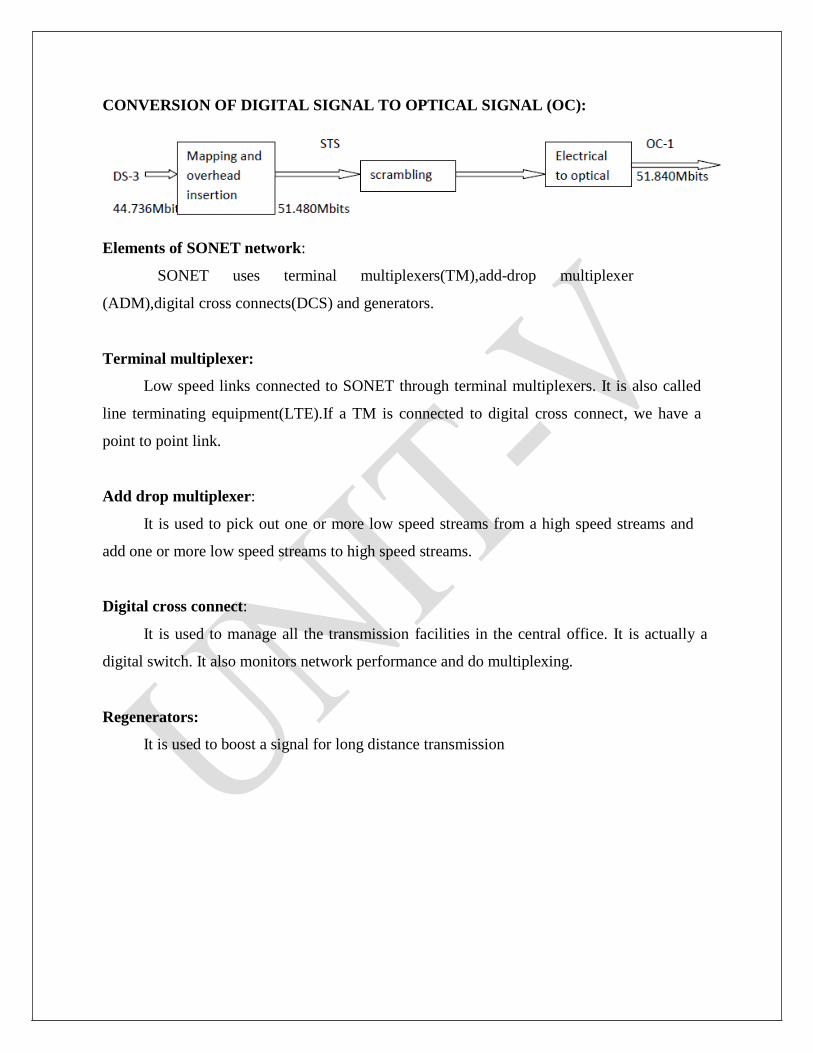
CONVERSION OF DIGITAL SIGNAL TO OPTICAL SIGNAL (OC):
Elements of SONET network:
SONET uses terminal multiplexers(TM),add-drop multiplexer
(ADM),digital cross connects(DCS) and generators.
Terminal multiplexer:
Low speed links connected to SONET through terminal multiplexers. It is also called
line terminating equipment(LTE).If a TM is connected to digital cross connect, we have a
point to point link.
Add drop multiplexer:
It is used to pick out one or more low speed streams from a high speed streams and
add one or more low speed streams to high speed streams.
Digital cross connect:
It is used to manage all the transmission facilities in the central office. It is actually a
digital switch. It also monitors network performance and do multiplexing.
Regenerators:
It is used to boost a signal for long distance transmission
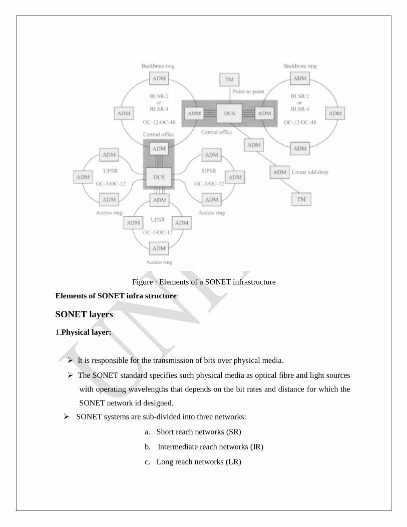
Figure : Elements of a SONET infrastructure
Elements of SONET infra structure:
SONET layers:
1.Physical layer:
It is responsible for the transmission of bits over physical media.
The SONET standard specifies such physical media as optical fibre and light sources
with operating wavelengths that depends on the bit rates and distance for which the
SONET network id designed.
SONET systems are sub-divided into three networks:
a. Short reach networks (SR)
b. Intermediate reach networks (IR)
c. Long reach networks (LR)

For short reach network, SONET recommended 1310nm operating wavelength
LED and multimode fiber.
For long reach network, SONET recommended 1550nm operating wavelength DFB
laser diode and single mode fiber. Physical layer is needed as each node.
2. Section layer:
It is responsible for sending data to the physical layer.
It interface with the physical layer by adding appropriate bytes to the frame overhead.
It also provides error monitoring and control.
It regenerates the signal and protect the multiplexing and switching operations.
Section layer is needed at each regenerator.
3. Line layer:
It is responsible for multiplexing many path layer connections onto a single link
between adjacent nodes.
This layer also provides most of the operating, administrative management and
provisioning (OAM& P) functions, including network protections.
A line layer needed at ADMS and TMS.
4. Path layer:
It is an end to end layer.
It is responsible for connections between a source and destination.
It accepts data from line layer, adds routing and error control information.
It also monitors and tracks the status of connection.
A path layer is needed at each SONET terminal multiplexer.
Passive Optical Network (PON):
PON use some form of passive components such as optical star coupler or static
wavelength router as the remote node.
Simple PON architecture uses a separate fiber pair from the CO to each ONU. The main
Problem with this approach is that cost of CO equipment scales with the number of ONU’s.
Moreover, the operator needs to install and maintain all these fiber pairs. This type of
architecture used to provide high speed service.
Instead of providing a fiber pair to each ONU, a single fiber can be used with Bidirectional
transmission. However the same wavelength cannot be used to transmit data simultaneously
in both the directions because of the uncontrolled reflection in the fiber.
One way is to use time division multiplexing so that both the ends does not
transmit simultaneously. Another is to use different wavelength (1.3 and
1.55µm,for example)for the different directions.
In PON architecture, fiber pair can also shared by many users.
Common example for such network is SONET/SDH rings. This type of network
provides high speed services to large business customers. An ONU is a SONET
add drop multiplexer(ADM),which can drop its information at particular
wavelength.
PON architecture types:
T PON-Passive Optical Network for Telephony.
W PON-Wavelength Division Multiplexing(WDM) Passive Optical Network.
WR PON-Wavelength Routing Passive Optical Network.
Disadvantages of PON:
The cost of CO equipment scales with number of ONU’s.
Operator needs to install and maintain all the pair of fibers coming from each ONU’s to
CO.
Advantages of PON:
Since this architecture is made from passive components, its reliability is very high.
Ease of maintenance.
Fiber infra structure itself is transparent to bit rate modulation formats and the overall
network can be upgraded in the future without changing the infra structure itself.
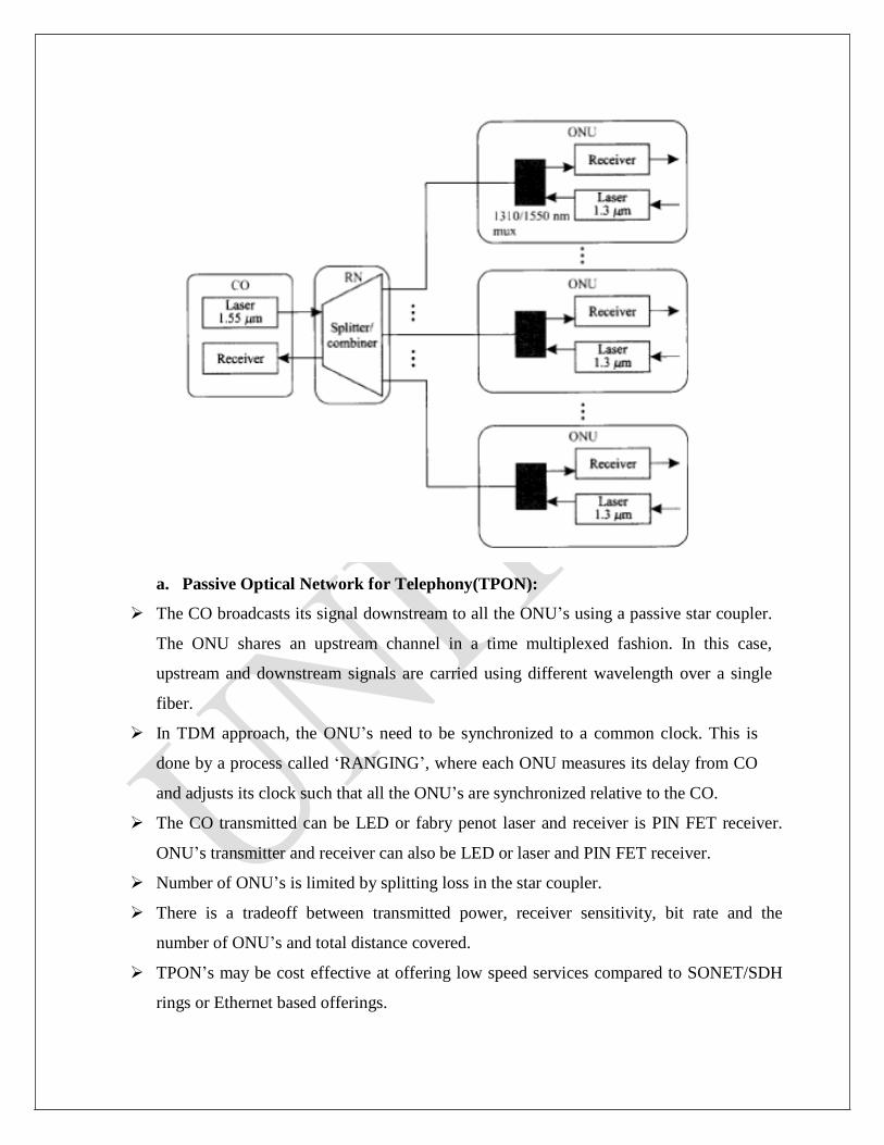
a. Passive Optical Network for Telephony(TPON):
The CO broadcasts its signal downstream to all the ONU’s using a passive star coupler.
The ONU shares an upstream channel in a time multiplexed fashion. In this case,
upstream and downstream signals are carried using different wavelength over a single
fiber.
In TDM approach, the ONU’s need to be synchronized to a common clock. This is
done by a process called ‘RANGING’, where each ONU measures its delay from CO
and adjusts its clock such that all the ONU’s are synchronized relative to the CO.
The CO transmitted can be LED or fabry penot laser and receiver is PIN FET receiver.
ONU’s transmitter and receiver can also be LED or laser and PIN FET receiver.
Number of ONU’s is limited by splitting loss in the star coupler.
There is a tradeoff between transmitted power, receiver sensitivity, bit rate and the
number of ONU’s and total distance covered.
TPON’s may be cost effective at offering low speed services compared to SONET/SDH
rings or Ethernet based offerings.
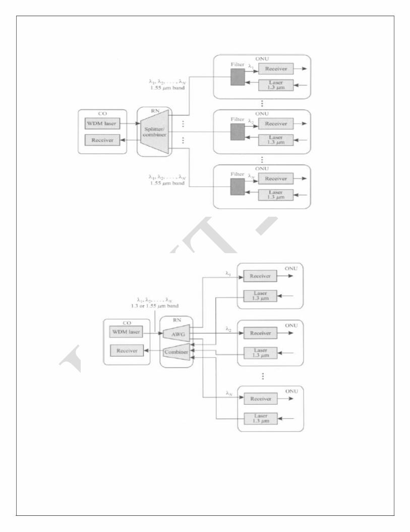
b. WDM PON:
It is an upgraded version of the basic PON architecture. In this case, the CO
broadcasts multiple wavelengths to all the ONU’s and each ONU select a
particular wavelength.
In this case, a single transceiver at the CO with WDM array of transmitters or
single tunable transmitter to yield (WDM PON).
This approach allows each ONU’s to have electronics running only at the rate it
receives data, and not at the aggregate bit rate.
However it is still limited by the power splitting at the star coupler.
c. WR PON- Wavelength routing PON:
In this case, a passive arrayed waveguide grating (AWG) is used to route different
wavelength to different ONUS in the down stream directions, without is curring a
splitting loss.
AS in the TPON and WPON architectures, the ONUS time shared wavelength for
Upstream transmission
It allows point to point dedicated services to be provided to ONUS.
FTTH: Fiber to the home
IN FTTC ie Fiber to the curb (or) Fiber to the building, data is transmitted digitally
over optical fiber from the hub, or central office, to fiber terminating nodes called
optical network units(ONU). The expectation is that fiber would get much closer to
the subscriber with this architecture.
IN FTTH (fiber to the home) architecture, the ONUS would perform the function of
NIU. Here the optical fiber is used to transmit data from central office to remote node
(RN) and RN to home.
In network from the co to ONU is typically a passive optical network(PON). The
remote node is a simple passive device such as an optical star coupler and it may some
be collocated in the central office itself rather than in the field.
Although many different architectural alternatives can be used for FTTC, the term
FTTC is usually used to describe a version where the signals are broadcast from the
central office to the ONUS, and the ONUS share a common total bandwidth in time
division multiplexed fashion.
In FTTC, the fiber is within about 100m of the end user. In this case, there is an
additional distribution network from the ONUS to the NIUS with the fiber to the
cabinet (FTTcab) approach, the fiber is terminated in a cabinet in the neighbourhood
and is within about 11cm of the end user.
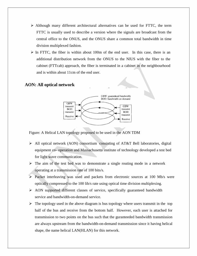
AON: All optical network
Figure: A Helical LAN topology proposed to be used in the AON TDM
All optical network (AON) consortium consisting of AT&T Bell laboratories, digital
equipment co- operation and Massachusetts institute of technology developed a test bed
for light wave communication.
The aim of the test bed was to demonstrate a single routing mode in a network
operating at a transmission rate of 100 bits/s.
Packet interleaving was used and packets from electronic sources at 100 Mb/s were
optically compressed to the 100 lib/s rate using optical time division multiplexing.
AON supported different classes of service, specifically guaranteed bandwidth
service and bandwidth-on-demand service.
The topology used in the above diagram is bus topology where users transmit in the top
half of the bus and receive from the bottom half. However, each user is attached for
transmission to two points on the bus such that the guranteeded bandwidth transmission
are always upstream from the bandwidth-on-demand transmission since it having helical
shape, the name helical LAN(HLAN) for this network.
Wavelength division Multiplexing (WDM):
A powerful aspect of an optical communication link is that many different wavelengths
can be sent along a single fiber simultaneously in the 1300 to 1600nm spectral band. The
technology of combining a number of wavelengths on to the same fiber is known as
wavelength division multiplexing or WDN.
Features of WDN:
Capacity upgrade:
If each wavelength support an independent network signal of perhaps a few giga bits
per second, then WDN can increase the capacity of fiber optic network dramatically.
Transparency:
Using different wavelengths, fast (Or) slow asynchronous and synchronous digital
data and analog information can be sent simultaneously and independently, over the same
fiber, without the need for a common signal structure.
Wavelength routing:
The use of wavelength sensitive optical routing devices makes it possible to use
wavelength as another dimension, in addition to the time and space in designing
communication networks and switches. In wavelength routed networks, use the actual wavelength as
intermediate (or) final address.
Wavelength switching:
Wavelength routed network-rigid configuration (can not be altered)
Wavelength switched network (WSN):
Allow the reconfiguration of optical network. Key components needed for WSN add
drop multiplexed .Optical cross connects and wavelength converters.
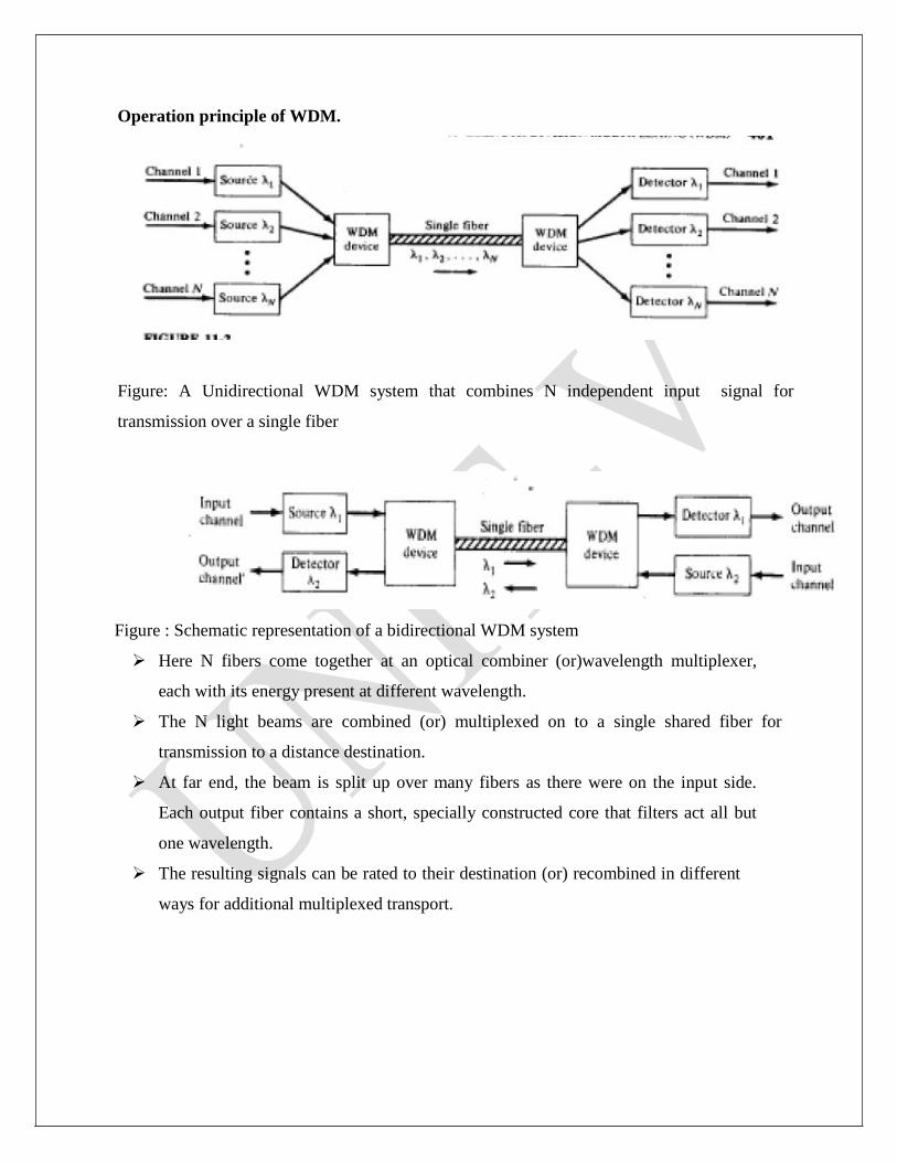
Operation principle of WDM.
Figure: A Unidirectional WDM system that combines N independent input signal for
transmission over a single fiber
Figure : Schematic representation of a bidirectional WDM system
Here N fibers come together at an optical combiner (or)wavelength multiplexer,
each with its energy present at different wavelength.
The N light beams are combined (or) multiplexed on to a single shared fiber for
transmission to a distance destination.
At far end, the beam is split up over many fibers as there were on the input side.
Each output fiber contains a short, specially constructed core that filters act all but
one wavelength.
The resulting signals can be rated to their destination (or) recombined in different
ways for additional multiplexed transport.
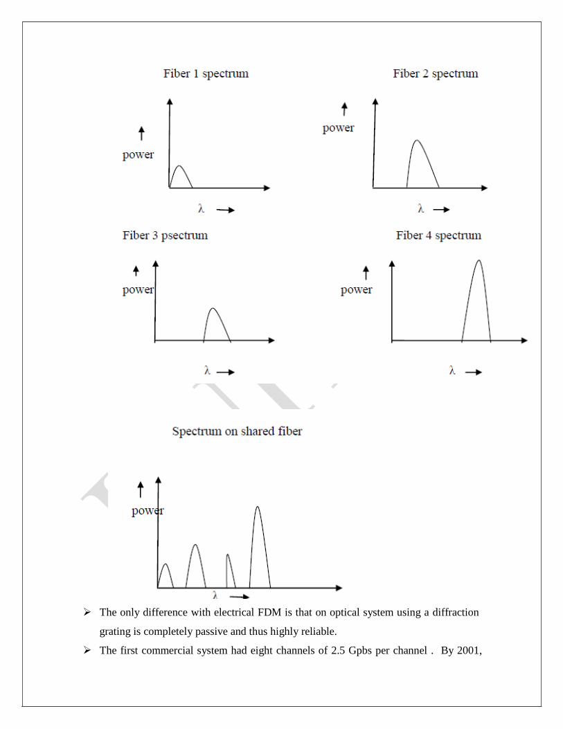
The only difference with electrical FDM is that on optical system using a diffraction
grating is completely passive and thus highly reliable.
The first commercial system had eight channels of 2.5 Gpbs per channel . By 2001,

there were products with 96 channels of 10 Gpbs , for a total of 960 Gbps.
When the number of channels is very large and wavelength are spaced close
together, for example 0.1nm, the system often referred to as DWDM (Dense
WDM).
By running many channels in parallel on different wavelength, the aggregate bandwidth is
increased linearly with the no. of channels. Since the bandwidth of single fiber band is
about 25,000 GHZ, there is theoretically room for 2500 10 GPPS channels even at 1
bit/HZ. (for DWDM, write same explanation with the diagram)


![SONET€¦ · Optical Interface Layers There are four optical interface layers in SONET. (section 3.3.1 of [3] and section 9.1 of [2]) They are the path layer, line layer, section](https://img.pdfslide.us/doc/110x75/5b5edfca7f8b9a415d8d4495/sonet-optical-interface-layers-there-are-four-optical-interface-layers-in-sonet.jpg)


![National Institute Of Science & Technology SONET Manjit Hota (EC200118144) [1] Synchronous Optical Network (SONET) Technical Seminar Presentation By Manjit](https://img.pdfslide.us/doc/110x75/56649d095503460f949dacff/national-institute-of-science-technology-sonet-manjit-hota-ec200118144.jpg)