Embed Size (px)
Citation preview

UNIT V
CLEANING AND INSPECTION OF CATSING
After the casting is extracted from the mould, it is no longer fit for use as such, as it has sprue, risers, etc.,
attached to it. Besides, it is not completely free of sand particles. This operation of cutting off the unwanted
parts, and cleaning and finishing the casting is known as fettling. The fettling operation may be divided into
different stages:
(1) knocking out of dry sand cores;
(2) removal of gates and risers;
(3) extraction of fins and unwanted projections at places where the gates and risers have been
removed and also elsewhere;
(4) cleaning and smoothening the surface; and
(5) Repairing castings to fill up blowholes, straightening the warped or deformed castings.
(1) Knocking out of Dry Sand Cores Dry sand cores may be removed by rapping or knocking with an
iron bar. For quick knocking, pneumatic or hydraulic devices may be employed. These devices,
besides knocking the cores, also help in cleaning and smoothening the casting.
(2) Removal of Gates and Risers The choice of method for removing gates and risers from the castings
depends upon the size and the shape of the casting and the type of the metal. The options for such
work are:
(i) knocking off or breaking with a hammer, which is particularly suited in case of grey iron castings
and other brittle metals
(ii) sawing with a metal cutting saw, which may be a band saw, a circular saw, or a power hacksaw
(a metal band saw of the 'do-all' type is considered suitable for steel, malleable iron, and non-
ferrous castings)
(iii) flame cutting with oxyacetylene gas, generally adopted for ferrous metals, especially for large-
sized castings where the risers and the gates are very heavy
(iv) using a sprue cutter for shearing of the gates
(v) employing abrasive cut-off machines, which can work with all metals but are specially designed
for hard metals, which are difficult to saw or shear
(vi) plasma arc cutting, now being increasingly used to cut sprues and risers of plate-shaped castings
with a view to eliminate the manual operation of burning off and to make the work fast, clean and
accurate, by using a programmable robot for holding and manipulating the castings.
(3) Removal of Fins and Unwanted Projections The operation of removing unwanted metal fins,
projections, etc., from the surface of the casting is called snagging. While snagging, care must be
exercised to see that a proper casting contour is followed and too much metal is not removed.
MEE54 INDUSTRIAL CASTING TECHNOLOGY
The methods for snagging include:
1) using grinders of pedestal, bench, flexible shaft, or swing-frame type;
2) chipping with hand or pneumatic tools;
3) gouging and flame-cutting;
4) removing metal by arc-air equipment; and
5) filing.
(4) Cleaning and Smoothening Castings
In the as-cast state, castings often have sand particles adhering to their surface in a fused form. When the
castings are heat-treated, a scale is also formed on the surface. In order that the casting surface be clean
and smooth, the adhering sand particles and the scale have to be removed. The various methods available
for this purpose are now described briefly.
1. Tumbling The castings to be cleaned are put in a large steel shell or barrel, which is closed at its ends
by cast-iron lids. The barrel is supported on horizontal trunnions and is rotated at a speed varying from
25-50 rpm. Along with the castings, small pieces of white iron called stars are also charged to help
complete the cleaning and polishing operations. When the barrel is rotated, it causes the castings to
tumble over and over again, rubbing against each other. Thus, by a continuous preening action, not
only do the castings get cleaned and polished but also the sharp edges and fins get eliminated and the
internal stresses in the castings are relieved.
When the barrel is charged, care should be taken to ensure that the castings are packed tight enough
to prevent any breakage. At the same time, these should not be so tight as to prevent the relative
motion of the adjacent pieces. The capacities of tumbling barrels (Fig. 8.1) may vary from 1-12 cu m.
The limitation of this process is that heavy castings cannot be charged with small ones of fragile nature.
Generally, small-sized castings, which are not fragile in nature, are best suited for tumbling.
2. Tumbling with Hydroblast In this method, the barrel is not horizontal bill is arranged obliquely at an
angle of about 30°. One end of the barrel, which is at a higher level than the other, may be kept open
to enable observation of the cleaning process. When the castings are tumbled, a high-velocity stream
of water and sand is blasted on the castings at a velocity of about 6000 metres per minute. This action
results in more efficient cleaning and polishing, and the tumbling time is also considerably reduced.
The method is better adapted to non-ferrous castings since ferrous ones tend to get corroded due
to water treatment. The base of the barrel is perforated to facilitate removal of the sand-and-water
mixture. For large castings, hydroblasting chambers are used. The castings are placed on a slowly
rotating table and a high-velocity stream is emitted from an adjustable nozzle.
3. Cleaning with Compressed Air Impact (Sand Blasting) A high-velocity stream of compressed air along
with abrasive particles is directed by means of a blast gun against the casting surface. The blast gun

MEE54 INDUSTRIAL CASTING TECHNOLOGY
is designed to convey air at high velocity into a mixing chamber. The abrasive is fed into this chamber
through a side tube by suction feed, gravity feed, or direct pressure. Generally, in the case of small
guns, the abrasive is drawn in the mixing chamber due to vacuum created by the passage of high-
velocity air. The abrasive used is either sand or steel grit. From the mixing chamber, air-borne sand
particles are directed towards the casting. Figure 8.2 shows a complete sand-blasting arrangement
which has a manually operated blast pipe.
The blasting operation is generally carried out in special cabinets or rooms where the operator
directs the blast against the castings to be cleaned. The discharged sand drops through a perforated
floor from where it is conveyed to the moulding shop for re-use. The room reserved for sand blasting is
provided with an exhaust system for collecting the dust and suitable mechanical means for handling
the castings. The small-sized castings are cleaned in cabinets equipped with windows through which
the operator can manipulate the gun and direct the blast. While working, the operator must be
thoroughly protected against harmful dust. He should wear large rubber gloves, protective clothing on
the body, and an air-pressurized helmet.
Unlike tumbling, the sand-blasting method can be adopted for both fragile and large-sized castings.
The method is also more efficient and ensures good polish.
4. Cleaning with Mechanical Impact (Shot Blasting) Instead of using air pressure for hurling the
abrasive grit towards the casting, centrifugal force may be exerted by means of an impeller wheel.
The abrasive applied in this case is steel shots. As the shots move from the hub of the impeller
towards the periphery, their velocity gets accelerated and they finally leave the impeller at a very
high velocity, hitting the casting surface with enormous impact. Large cleaning units may be
equipped with one or more blasting impellers strategically positioned at different places all around
the casting. The casting may also be mounted on a rotating table (Fig. 8.3). I n some units, the
castings are tumbled and at the same time the abrasive is hurled towards them. In a monorail-type
shot blast, the castings are carried by a power conveyer into the machine from one side and taken
out from the other side.
(5) Repairing the Castings
Defects such as blowholes, gas holes, cracks, etc., may often occur in castings. Sometimes the
castings get broken, bent, or deformed during shake-out or because of rough handling. Often the castings
get, warped during heat treatment or while they cool down in the mould. Such defective castings cannot
be rejected outright for reasons of economy. They are therefore repaired by suitable means and put to use
unless the defects are such that they cannot be remedied. The common methods of repair are now dealt
with.
(i) Metal-Arc Welding Large-sized cracks, blowholes, and other imperfections can be rectified by metal-
arc welding. The area to be welded must first be cleaned by chipping, filing, gouging, or grinding. Then

MEE54 INDUSTRIAL CASTING TECHNOLOGY
the joint must be accurately prepared and, if necessary, widened before welding is commenced.
Metals that can be welded by this method include almost all cast metals, except magnesium. A proper
selection of welding electrode is vital. AC metal-arc welding is most often selected for welding steel
castings. The electrodes used should preferably be coated so that a dense and strong joint is
produced. DC arc welding is preferred for welding cast irons and non-ferrous metals as the polarity
can be changed and more heat can be obtained on either the electrode or the workpiece, as desired.
DC welding can thus give lower electrode consumption, higher metal deposition rates and smoother
welds. It is also less dangerous, the arc voltage used being lower than in the case of AC welding.
(ii) Oxy-acetylene Gas Welding This method, which is the least expensive and easily portable, is suitable
where the sections to be welded are not too heavy and when- slower cooling rates are required, for
instance, to prevent hardenable steels from getting hardened. Gas welding can easily allow the use of
a broad flame, which can pre-heat the area ahead of the section being welded. This is not possible in
arc welding. The flame temperature is also lower than that of the arc, so cooling rates are slow. The
flame can be adjusted so as to make it oxidising, reducing, or neutral. An oxidising flame is used for
welding brasses and bronzes, reducing flame for high carbon and alloy steels, nickel alloys, and other
hard-facing materials, and a neutral flame for low carbon steels. By using the proper technique, almost
all cast metals and alloys, except magnesium, can be gas welded. Liquefied petroleum gas (LPG) or
natural gas is also used in place of acetylene where a broad flame is desired.
(iii) Carbon Arc Welding Here the electrode is not made of consumable metal but of carbon, and a separate
filler rod is fed into the arc to acquire deposition. The method is suitable for all foundry alloys except
magnesium and particularly suited for welding copper base and aluminium alloys.
(iv) Inert Gas Tungsten Arc Welding (TIG Process) This process uses a non-consumable type of tungsten
electrode together with a shield of inert gas, such as helium and argon for protection of the welding
zone. It is most suitable for metals that tend to get quickly oxidised, for instance, magnesium and
magnesium alloys. It is also widely used for welding thin aluminium castings as also for stainless steels
and alloys of copper and nickel.
(v) Inert-Gas Metal-Arc Welding (MIG Welding) The electrode is made of metal similar to the work metal
and is of the consumable type. The method is very fast as the electrode wire is automatically fed, and
the inert gas protects the metal from oxidation. The gases used are argon, nitrogen, and carbon
monoxide. The method is suitable for the repair and joining of large-sized steel castings and is
economical where high speed of operation is required.
(vi) Submerged Arc Welding In this case, the entire welding action takes place beneath a granular mineral
material which acts as flux (Fig. 5.1). The electrode used is in bare form. The flow of current melts the
flux, spreading it over the weld zone and keeping the arc and weld metal submerged. The metal is
thus completely protected from oxidation; besides, there is no visible arc, sparks, spatter, or smoke.
This enables use of heavy welding currents, high welding speeds, deeper penetration, and superior

MEE54 INDUSTRIAL CASTING TECHNOLOGY
quality of welds. The method is unsuitable for repair work as it is basically a production process, but it
is adopted for building up large pressure vessels or structures by welding together smaller steel
castings.
Fig. 5.1 Submerged Arc Welding
(vii) Atomic Hydrogen Welding A continuous stream of hydrogen is passed through the arc produced
between two tungsten electrodes. Due to the heat of the arc, the gas dissociates from molecular to
atomic form. When the atoms of hydrogen strike the cooler work surface, they again re-unite and emit
an enormous amount of heat, thus melting the base metals that need to be joined. The heat input thus
available is very high; moreover, hydrogen also acts as a shield against the action of atmospheric
oxygen and nitrogen. Filler metal is fed separately from a wire. This process is ideal for the repair
welding of metal moulds and dies made of alloy steels, and is also used for welding of thin castings in
stainless steel, aluminium alloys, etc., It produces a very homogeneous and smooth joint with strength
that equals that of the parent metal.
(viii) Thermit Welding The high temperature required for melting metal to fill up the joint is attained by
employing an exothermic reaction. The method is more like a casting process. It entails igniting in a
crucible a mixture of iron oxide and finely divided aluminium in the ratio of 3: 1 and a special powder
used to ignite the mixture. Due to the heat of ignition, the mixture explodes at a temperature of about
1540°C, and pure iron with aluminium oxide as slag is produced:
8Al + 3Fe304 -> 9Fe + 4Al2O3
The joint, crack or cavity to be filled is arranged in a sand mould with a proper gating and feeding
system and the metal from the thermit crucible is poured into the mould. Pure metal occupies the space
between the pieces to be joined and slag floats at the top. To enable preparation of the sand mould in
one piece, wax is placed in the joint space and around, and the gating system, also in wax, is attached.
The whole assembly is embedded in moulding sand and the mould inverted and heated to cause the
wax to melt and flow out, leaving the cavity around the metal parts to be joined as shown in Fig. 5.2.

MEE54 INDUSTRIAL CASTING TECHNOLOGY
Fig. 5.2 Arrangement of thermit welding for casting repair
Thermit welding is employed for repairing large and heavy steel castings such as steel mill rolls,
ship-stern frames, and gears. It is also used for the fabrication of heavy units by joining relatively simple
castings. The process is simpler, less time-consuming, and cheaper than other methods and produces
good strength and better quality. Also, no stress relief is necessary as the cooling is very slow and the
operation itself relieves the stresses.
(ix) Flow Welding This entails melting the metal, in the same way as for casting purposes, and then
continuously pouring the molten metal directly into the crack or cavity to be filled, till the surrounding
area also starts melting. The excess metal is then removed by grinding or machining. This method is
not much favoured now as easier and quicker methods of welding are available.
(x) Braze Welding This process is applied for such parts that tend to get distorted or cracked when welded
by other means. A lower heat input is required as the base metal is not actually melted and the bond
is obtained only by diffusion. A non-ferrous copper base or silver base alloy which melts at a
temperature above 430°C is employed as filler metal. It is introduced in the liquid state in between the
pieces that are to be joined. The method may be used to make castings watertight and to repair pipes
and pipe fittings and other thin plate-type castings for filling fine cracks, crevices, porosity, etc.
(xi) Soldering This is similar to brazing, the difference being in the filler metal: a tin-lead alloy which melts
at a much lower temperature (below 430°C) is preferred for soldering. The process serves to fill up
surface imperfections when high strength is not required and porous areas in copper-base alloy
castings are to be made pressure tight.
(xii) Resin Impregnation Where welding or brazing cannot effectively fill the porous areas of a casting, resin

impregnation often admirably serves the purpose. The process entails forcing a resin to enter the
MEE54 INDUSTRIAL CASTING TECHNOLOGY
pores under pressure while the casting is kept under vacuum. Resin impregnation equipment is
expensive but works out worthwhile for foundries where pressure-tight castings, either ferrous or non-
ferrous, are regular products. IS: 12799-1989 describes the recommended practice for impregnation
of castings.
(xiii) Epoxy Fillers Certain epoxy plastic fillers can be used to fill up pinholes, blowholes and cracks, and to
impart enough strength to the casting. For good mechanical properties, fillers are also duly charged
with metal powders to suit different cast metals. These fillers are of two types, viz., general purpose
and fast-curing. The latter takes hardly two hours to harden whereas the former takes longer. Smooth-
on cement, which is a pasty mixture of iron filings in a hardening agent, is also widely used to repair
iron castings.
(xiv) Straightening Deformed or warped castings can be straightened in a press by applying pressure. This
operation is possible only in the case of ductile materials, such as steel, aluminium, copper, and
bronze. Generally, a hydraulic press is used along with formed dies. Small castings can also be
straightened by hammering manually. Both cold and hot pressing are used according to size and
material of casting.
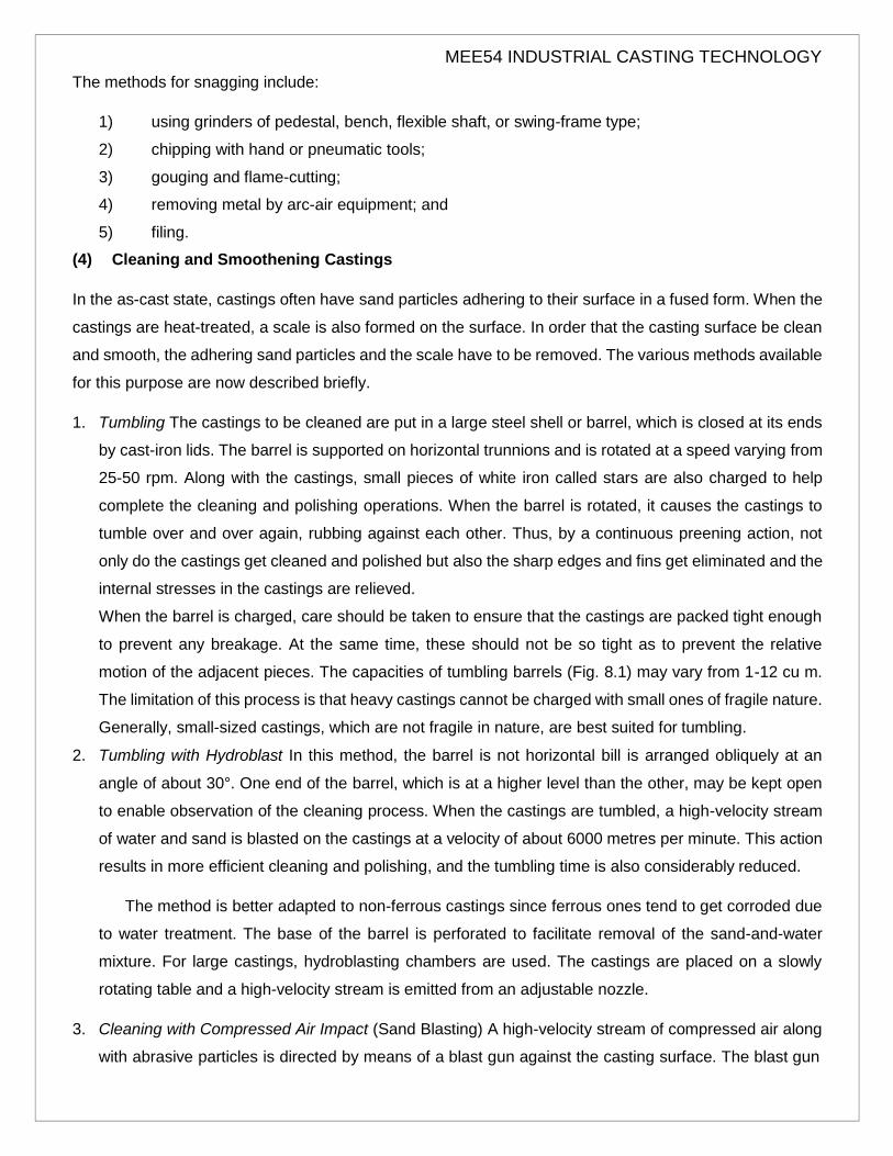
(xv) Metal Spraying When the casting becomes undersized, it can be built up by providing a coat of metal
in the desired thickness by a metal-spraying process. This is a simple and relatively inexpensive way
of forming a layer of metal on the cast surface. The sprayed metal may be either the same as the base
metal or a dissimilar one. The deposited metal is taken in wire form. The spray gun uses oxygen and
acetylene to melt the wire and compressed air to atomise the molten metal in the form of spray. All
types of metals and alloys can be sprayed. The bond obtained is of the mechanical type with negligible
diffusion. The joint between the parent metal and the sprayed metal is not as strong as that obtained
by welding or brazing. This technique is also used for providing an anticorrosive metal layer on iron
and steel castings. Fig. 5.3 explains the principle of metal spraying and Fig. 5.4 shows the set-up
required for the process.
Fig. 5.3 Metal Spraying

MEE54 INDUSTRIAL CASTING TECHNOLOGY
Fig. 5.4 Set-up for metal spraying
HEAT TREATMENT OF CASTINGS
Heat treatment involves the improvement of the properties of materials by bringing about certain permanent
structural changes. Modern demands for high-quality castings have made heat treatment an indispensable
step between the casting process and the finished product for engineering applications.
DEFECTS IN SAND CASTINGS
There are numerous opportunities for things to go wrong in a casting operation, resulting in quality defects
in the cast product. Some defects are common to any and all casting processes. These defects are
discussed below:
(1) Misruns: castings that solidify before completely filling the mould cavity. This occurs because of (1)
low fluidity of the molten metal, (2) low pouring temperature, (3) slow pouring, (4) thinner cross-section
of the mould cavity
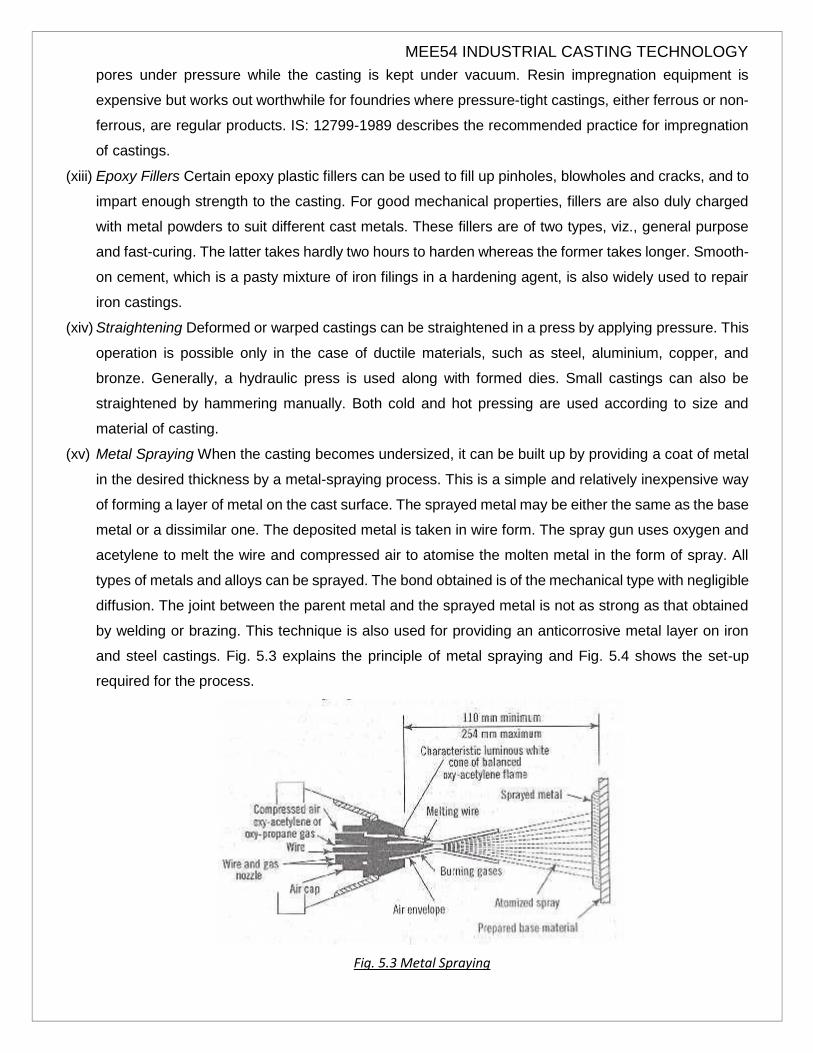
(2) Cold Shuts: This defect occurs when two portions of the metal flow together but no fusion occurs
between them due to premature freezing. Causes:
a) low temperature of molten metal b) improper gating system c) too thin casting sections
MEE54 INDUSTRIAL CASTING TECHNOLOGY
d) slow and intermitted pouring e) improper alloy composition f) use of damaged pattern
Remedies: a) Smooth pouring with the help of monorail. b) Properly transport mould during pouring. c) Arrange proper clamping arrangement. d) providing appropriate pouring temperature.
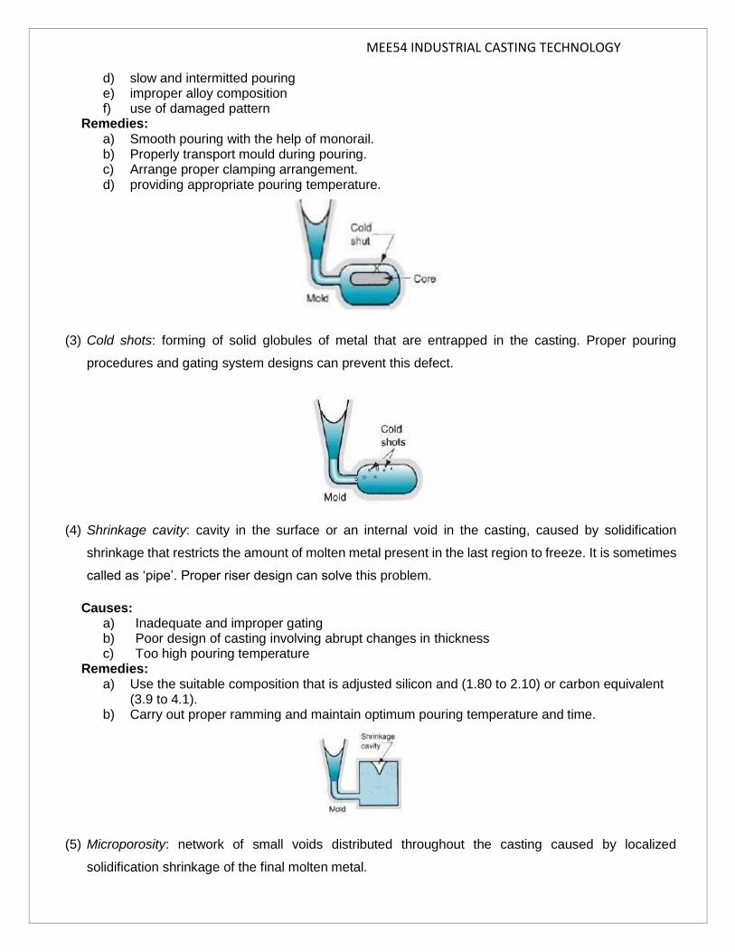
(3) Cold shots: forming of solid globules of metal that are entrapped in the casting. Proper pouring
procedures and gating system designs can prevent this defect.
(4) Shrinkage cavity: cavity in the surface or an internal void in the casting, caused by solidification
shrinkage that restricts the amount of molten metal present in the last region to freeze. It is sometimes
called as ‘pipe’. Proper riser design can solve this problem.
Causes: a) Inadequate and improper gating b) Poor design of casting involving abrupt changes in thickness c) Too high pouring temperature
Remedies: a) Use the suitable composition that is adjusted silicon and (1.80 to 2.10) or carbon equivalent
(3.9 to 4.1). b) Carry out proper ramming and maintain optimum pouring temperature and time.
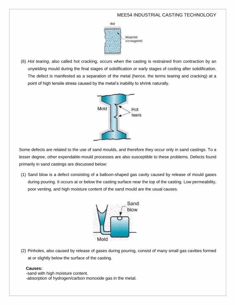
(5) Microporosity: network of small voids distributed throughout the casting caused by localized
solidification shrinkage of the final molten metal.
MEE54 INDUSTRIAL CASTING TECHNOLOGY
(6) Hot tearing, also called hot cracking, occurs when the casting is restrained from contraction by an
unyielding mould during the final stages of solidification or early stages of cooling after solidification.
The defect is manifested as a separation of the metal (hence, the terms tearing and cracking) at a
point of high tensile stress caused by the metal’s inability to shrink naturally.
Some defects are related to the use of sand moulds, and therefore they occur only in sand castings. To a
lesser degree, other expendable-mould processes are also susceptible to these problems. Defects found
primarily in sand castings are discussed below:
(1) Sand blow is a defect consisting of a balloon-shaped gas cavity caused by release of mould gases
during pouring. It occurs at or below the casting surface near the top of the casting. Low permeability,
poor venting, and high moisture content of the sand mould are the usual causes.
(2) Pinholes, also caused by release of gases during pouring, consist of many small gas cavities formed
at or slightly below the surface of the casting.
Causes: -sand with high moisture content. -absorption of hydrogen/carbon monoxide gas in the metal.

MEE54 INDUSTRIAL CASTING TECHNOLOGY
-alloy not being properly degassed. -steel is poured from wet ladles. -sand containing gas producing ingredients. Remedies: -reducing the moisture content of moulding sand. -increasing its permeability. -employing good melting and fluxing practices. -improving a rapid rate of solidification.
(3) Sand wash: surface dip that results from erosion of the sand mould during pouring. This contour is
formed in the surface of the final cast part.
(4) Scab: It is caused by portions of the mould surface flaking off during solidification and gets embedded
in the casting surface.
(5) Penetration: surface defect that occurs when the liquid penetrates into the sand mould as the fluidity
of liquid metal is high, After solidifying, the casting surface consists of a mixture of sand and metal.
Harder ramming of sand mould minimize this defect.

MEE54 INDUSTRIAL CASTING TECHNOLOGY
(6) Mould shift: defect caused by displacement of the mould cope in sideward direction relative to the
drag. This results in a step in the cast product at the parting line.
Causes: -worn dowel in patterns made in halves. -improper alignment of mould boxes due to worn out/ill fitting mould boxes. Remedies: - Properly arrange box warpage. - Properly move boxes with pins. - Properly clamp the boxes.
(7) Core shift: displacement of core vertically. Core shift and mould shift are caused by buoyancy of the
molten metal.
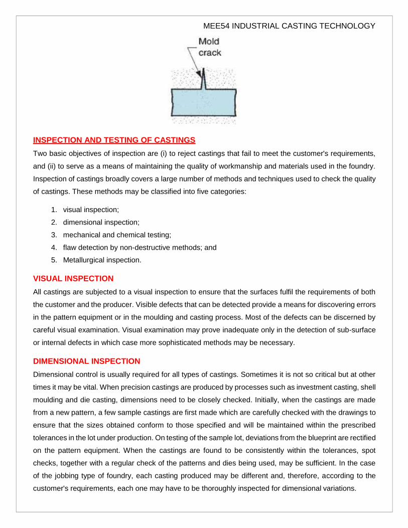
(8) Mould crack: ‘fin’ like defect in cast part that occurs when mould strength is very less, and a crack
develops, through which liquid metal can seep.
MEE54 INDUSTRIAL CASTING TECHNOLOGY
INSPECTION AND TESTING OF CASTINGS
Two basic objectives of inspection are (i) to reject castings that fail to meet the customer's requirements,
and (ii) to serve as a means of maintaining the quality of workmanship and materials used in the foundry.
Inspection of castings broadly covers a large number of methods and techniques used to check the quality
of castings. These methods may be classified into five categories:
1. visual inspection;
2. dimensional inspection;
3. mechanical and chemical testing;
4. flaw detection by non-destructive methods; and
5. Metallurgical inspection.
VISUAL INSPECTION
All castings are subjected to a visual inspection to ensure that the surfaces fulfil the requirements of both
the customer and the producer. Visible defects that can be detected provide a means for discovering errors
in the pattern equipment or in the moulding and casting process. Most of the defects can be discerned by
careful visual examination. Visual examination may prove inadequate only in the detection of sub-surface
or internal defects in which case more sophisticated methods may be necessary.
DIMENSIONAL INSPECTION
Dimensional control is usually required for all types of castings. Sometimes it is not so critical but at other
times it may be vital. When precision castings are produced by processes such as investment casting, shell
moulding and die casting, dimensions need to be closely checked. Initially, when the castings are made
from a new pattern, a few sample castings are first made which are carefully checked with the drawings to
ensure that the sizes obtained conform to those specified and will be maintained within the prescribed
tolerances in the lot under production. On testing of the sample lot, deviations from the blueprint are rectified
on the pattern equipment. When the castings are found to be consistently within the tolerances, spot
checks, together with a regular check of the patterns and dies being used, may be sufficient. In the case
of the jobbing type of foundry, each casting produced may be different and, therefore, according to the
customer's requirements, each one may have to be thoroughly inspected for dimensional variations.

MEE54 INDUSTRIAL CASTING TECHNOLOGY
Dimensional inspection of castings may be conducted by various methods:
(i) Standard Measuring Instruments to Check the Sizes Instruments such as rule, vernier calipers, vernier
height gauge, vernier depth gauge, micrometers, scribing block, combination set, straight edge,
squares, spirit level, and dial indicator are commonly used. For high precision castings or after
machining, more advanced measuring instruments, such as auto-collimator, comparator, ultrasonic
instruments for measuring wall thickness and projection instruments are also required.
(ii) Templates and Contour Gauges for the Checking of Profiles, Curves, and Intricate Shapes Templates
act as time-saving aids in measurement and facilitate the entire job. These can be easily prepared in
mild steel or brass sheet by marking out, and cutting and finishing the profile that is required to be
checked on the castings.
(iii) Limit Gauges For toleranced dimensions on casting produced on a repetitive basis, limit gauges are
usually used. The type of limit gauges—plug, ring, snap, plate—depends on the shape of the
parameter to be checked. Periodical checking and maintenance of limit gauges is very important.
(iv) Special Fixtures Special fixtures are required to be designed and used where dimensions cannot be
conveniently checked by using instruments, for instance, during the checking of locations, relative
dimensions, centre-to-centre distance, angularity of surfaces, and so on.
(v) Coordinate Measuring and Marking Machine (CMM) This machine is very useful for measurement and
inspection of uneven, undulated, irregular, or curved surfaces which cannot be conveniently or
accurately checked by other measuring tools or instruments. The accuracy of measurement of these
machine ranges from 0.001 mm to 0.05 mm. Besides measuring, it can be used for marking purposes
also in all three dimensions on metallic or non-metallic surfaces. Measurement and marking are
accomplished easily without errors in reading in all three dimensions. Once the machine is set, all
measurements can be carried out in a programmed sequence automatically. The machine in reality is
a multi-axial device providing measurement of output of position and displacement sequentially without
a need for changing tools.
The machine essentially consists of a touch probe, usually having a ruby tip, which is mounted on
a horizontally sliding arm, movable vertically along a column. The column is fixed to a base which in
turn is held on a large accurately machined granite surface plate and is movable in a direction
perpendicular to the direction of the movement of arm. Thus, the probe is capable of being moved
along all three axes for carrying out measurement of different surfaces of a workpiece. The sliding
movements of the arm and column are performed with great precision and are read on an electronic
digital read-out unit, attached to the machine. When marking is to be done on surfaces, a scriber is
used in place of a probe. A larger variety of probes, scribers and other accessories are available to
enable the machine to be highly flexible and accurate in operation. The movements along the three
axes may be manual or motorised. The machine can be further equipped with a small computer system
for processing the data obtained from measurement and for storing and retrieving the same.

MEE54 INDUSTRIAL CASTING TECHNOLOGY
A special software is also available with the computer so that measurement and inspection of
different types of surfaces can be carried out automatically without the need for manual control. The
drawing data from CAD station can be also transmitted to this machine by interlinking the two systems
with the actual value of dimensions. A printer can also be provided with the computer for producing a
hard copy of the inspection report. The CMM machines are now getting increasingly popular in
inspection departments attached to tool rooms, pattern and die shops, foundry and forging shops,
press shops, welding and structural shops and plastic and glass-part manufacturing units.
MECHANICAL AND CHEMICAL TESTING
All foundries should have facilities for determining the mechanical properties of a cast metal and its
chemical composition. Mechanical testing methods include certain procedures which require a standard
type of equipment. These are:
(i) tensile test to determine the tensile strength, yield strength, percentage elongation, and
percentage reduction in area,
(ii) bend, notch bend, and impact transverse tests to evaluate the ductility and resistance to shock
of the cast metal;
(iii) hardness test, which can indicate the strength and ductility of the metal (often, only hardness
testing is conducted with visual inspection. Other tests are used only when so required);
(iv) fatigue test, applied in cases where an appraisal of the life of the casting in service is to be
known; and
(v) tests for damping capacity and wear resistance.
Chemical testing is required to determine allowable limits. In the case of ferrous castings, it is necessary
to know the percentage of carbon, silicon, sulphur, manganese, and phosphorus contents. The presence
of alloying elements or metallic inclusions, such as Cr, Ni, Cu, Mg, W, V, Mo and Co, may also have to be
determined. Chemical analysis can be used in all such cases to accurately ascertain the composition,
though certain tests may be too cumbersome and time-consuming.
In many instances, it is necessary to quickly determine the content of carbon, silicon, and sulphur. This
may also have to be regularly checked where a close control of the composition of metal is consistently
required. Certain quick tests have been developed for such cases. One such test, commonly used in the
case of grey iron, malleable iron, and ductile iron, is called Carbon Equivalent Measurement.
Carbon equivalent (CE) is given by
Total carbon % + %
Since silicon has a predominant effect on the graphitising tendency of iron, the cumulative effect of carbon
and silicon can indicate the strength characteristics of the iron produced. For shop floor use, a measuring
MEE54 INDUSTRIAL CASTING TECHNOLOGY
instrument, known as 'instant carbon sensor' that quickly assesses CE. is available. It works on the principle
that CE is directly related to the liquidus arrest temperature of the metal. The instrument is equipped to
hold molten metal in a small reservoir over a chromel-alumel thermocouple and the temperature of the
metal, as it solidifies in the reservoir, is registered on the chart of the temperature recorder. From this chart
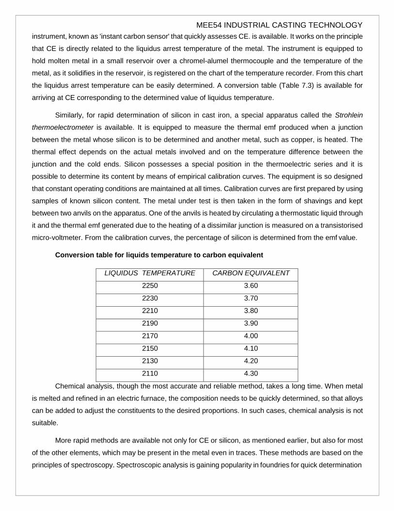
the liquidus arrest temperature can be easily determined. A conversion table (Table 7.3) is available for
arriving at CE corresponding to the determined value of liquidus temperature.
Similarly, for rapid determination of silicon in cast iron, a special apparatus called the Strohlein
thermoelectrometer is available. It is equipped to measure the thermal emf produced when a junction
between the metal whose silicon is to be determined and another metal, such as copper, is heated. The
thermal effect depends on the actual metals involved and on the temperature difference between the
junction and the cold ends. Silicon possesses a special position in the thermoelectric series and it is
possible to determine its content by means of empirical calibration curves. The equipment is so designed
that constant operating conditions are maintained at all times. Calibration curves are first prepared by using
samples of known silicon content. The metal under test is then taken in the form of shavings and kept
between two anvils on the apparatus. One of the anvils is heated by circulating a thermostatic liquid through
it and the thermal emf generated due to the heating of a dissimilar junction is measured on a transistorised
micro-voltmeter. From the calibration curves, the percentage of silicon is determined from the emf value.
Conversion table for liquids temperature to carbon equivalent
LIQUIDUS TEMPERATURE CARBON EQUIVALENT
2250 3.60
2230 3.70
2210 3.80
2190 3.90
2170 4.00
2150 4.10
2130 4.20
2110 4.30
Chemical analysis, though the most accurate and reliable method, takes a long time. When metal
is melted and refined in an electric furnace, the composition needs to be quickly determined, so that alloys
can be added to adjust the constituents to the desired proportions. In such cases, chemical analysis is not
suitable.
More rapid methods are available not only for CE or silicon, as mentioned earlier, but also for most
of the other elements, which may be present in the metal even in traces. These methods are based on the
principles of spectroscopy. Spectroscopic analysis is gaining popularity in foundries for quick determination

MEE54 INDUSTRIAL CASTING TECHNOLOGY
of the constituent elements including the trace elements. Various types of spectroscopic analyzers are
available, the selection depending on the nature of requirements in terms of the elements to be checked,
the accuracy desired, the frequency at which tests are to be conducted, and the type of cast metal.
A microprocessor-based system operating on the principle of thermal analysis is also available for
quick determination of carbon equivalent, total carbon, silicon and temperature of molten metal. It can be
used for various cast metals like grey iron, malleable iron, SG iron, steel and copper-base alloys. The
instrument is equipped with a digital display. A print-out is also obtained for permanent record. It has a high
degree of accuracy, e.g., within ± 0.05% for carbon equivalent and total carbon and within ± 0.15% for
silicon.
FLAW DETECTION BY NON-DESTRUCTIVE METHODS
Non-destructive tests are also required to be conducted in foundries to examine the castings for
any sub-surface or internal defects, surface defects, which cannot be detected by visual examination and
for overall soundness or pressure tightness, which may be required in service. These tests are valuable
not only in detecting but even in locating the casting defects present in the interior of the casting, which
could impair the performance of the machine member when placed in service. Parts may also be examined
in service, permitting their replacement before the actual failure or breakdown occurs.
The important non-destructive test for castings include:
1. sound or percussion test (stethoscope test);
2. impact test;
3. pressure test;
4. radiographic examination;
5. magnetic particle inspection;
6. electrical conductivity test;
7. fluorescent dye-penetrant inspection;
8. ultrasonic test; and
9. Eddy current test.
1. Sound or Percussion Test (Stethoscope Test): This is an old method, which has been refined over the
years. Basically, it entails suitably supporting the suspension of the part by chains or other equipment,
permitting the part to swing free of the floor and other obstructions, and then tapping it with a hammer. The
weight of the hammer blows is so adjusted that vibrations will be set up in the casting producing a certain
characteristic tone which may or may not change the wavelength of sound produced by the blows.

MEE54 INDUSTRIAL CASTING TECHNOLOGY
The stethoscope test serves to detect relatively large discontinuities in an otherwise homogeneous metal
and may be successful when applied to simple shapes and uniform cross sections. The drawback of the
method is that it is difficult to judge the extent of the defect and to locate the fault.
2. Impact Test This test may be destructive or non-destructive in nature, depending on the quality of
casting. Moreover, it cannot be used in all cases as it can damage the casting.
A hammer of appropriate size is used to strike or fall on certain members of the casting where the defect
is suspected. It is expected that the casting containing harmful defects will break and will thus be
automatically rejected whereas those that are faultless will stand the test.
A variation of this method involves dropping the casting from a specified height onto a steel base.
Obviously, the method of testing is not very reliable and sometimes even the defect-free castings may
break. This method is therefore sparingly used these days.
3. Pressure Test This method is employed to locate leaks and to test overall strength of certain parts,
such as cylinders, valves, pipes, and fittings, which are required to hold or carry fluids in service under
various amounts of pressure. The fluid used in testing may be water, air, or steam. Water being
incompressible is generally preferred since danger is minimized even if the casting should shatter due to
pressure. The pressure may vary from one and a half times to two times the working pressure. For safety
reasons, the pressure is generally applied by means of a small hand pump. A leak, even if it is not located
immediately, may be detected on the pressure gauge. Steam tests have the advantage that steam can
press through smaller holes or openings through which water may not readily pass. Besides, the heat of
the steam also causes minute cracks to widen due to expansion. While testing pneumatically, the casting
is immersed in a tank carrying water and then the air pressure is applied. If there is a leak, air bubbles are
formed.
4. Radiographic Examination Radiography is a non-destructive test for detection of internal voids in
castings. Electromagnetic waves having low wavelengths (varying between 10-6 and 10~10 cm) are used
as a means of inspection. These waves, generally called X-rays, have properties similar to those of light
waves, but they have much shorter wavelengths, which lie outside the range of human sensitivity. These
X-rays can, however, be detected by a sensitive photographic film. Owing to their shorter wavelengths,
these waves can penetrate materials that are normally opaque to light. The denser the material, the shorter
the wavelength required to penetrate it. The test can be applied to all grades of iron and steel castings,
though it is an expensive method of inspection.
The X-rays are produced by an X-ray tube which carries two sealed copper elements, the cathode and the
anode. The cathode bears an electrically heated filament which generates electrons; when these electrons
strike the tungsten target fixed to the anode they are driven towards the positively charged anode. The
striking of the electrons causes their kinetic energy to be partly converted into heat, which is conducted
MEE54 INDUSTRIAL CASTING TECHNOLOGY
away through the cooling fins provided on the anode and the remainder of the energy is converted into
electromagnetic waves, termed X-rays. The X-rays pass out of the tube through a window in the form of a
beam. The intensity of these X-rays is controlled by regulating the current passing through the filament.
Similarly, the wavelength of the ray is inversely proportional to the voltage applied between the two poles.
The shorter the wavelength, the greater the depth of penetration.
If there is a cavity or a hole in the casting under inspection, and, when such a casting is kept against the
X-rays, the rays finding less obstruction penetrate more freely than at the place where the metal is more
dense and solid. The rays that penetrate and emerge from the casting are absorbed by a photographic
plate. Thus the part of the photographic plate opposite the defect will receive more rays and will be more
exposed than the rest of the plate. This will produce a contrasting image on the negative. For more accurate
results, special films with an emulsion coating are found suitable. Sometimes, in place of a photographic
plate, fluoroscopic screens are used; these screens are made of materials that fluoresce when exposed to
X-rays in a dark room. To protect the viewer from continuous exposure to the rays, the image of the screen
is observed in a mirror, which is so placed that observer is located out of the path of the X-rays. The
voltages required for the X-ray machines depend on the density of the metal and its section thickness.
Like X-rays, gamma rays which are emitted during the decomposition of radium, are also suitable for the
inspection of castings. The wavelengths of these rays range between 10~75 and 10~105 cm and since
these are shorter than X-rays they can penetrate metals more easily. Due to their high penetrating power,
the radiation absorbed by the photographic film is negligible and the remainder passes through the film.
Further, the difficulty experienced during the observation of thick and thin sections simultaneously is also
less than when using X-rays. But due to the high cost of radium and the need for expensive protective
equipment, the technique is used to a limited extent.
Radiography does not enable detection of cracks. The position of defects in the section also cannot be
easily defined unless special techniques are employed. Interpretation of radiographs depends on a
subjective assessment and hence requires proficiency in the work along with experience. Castings which
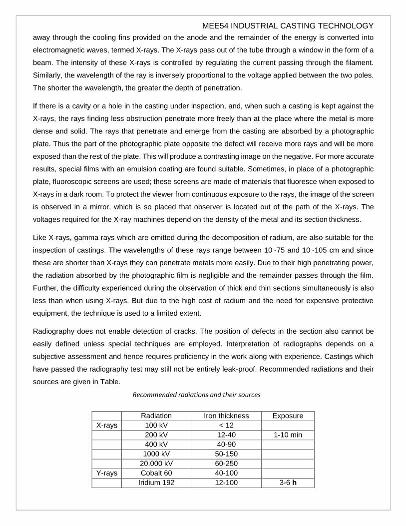
have passed the radiography test may still not be entirely leak-proof. Recommended radiations and their
sources are given in Table.
Recommended radiations and their sources
Radiation Iron thickness Exposure
X-rays 100 kV < 12
200 kV 12-40 1-10 min
400 kV 40-90
1000 kV 50-150
20,000 kV 60-250
Y-rays Cobalt 60 40-100
Iridium 192 12-100 3-6 h

Cesium 137 20-200

MEE54 INDUSTRIAL CASTING TECHNOLOGY
5. Magnetic Particle Inspection This test is used to reveal the location of cracks that extend to the
surface of iron or steel castings, which are magnetic in nature. The casting is first magnetised and then
iron particles are sprinkled all over the path of the magnetic field. The particles align themselves in the
direction of the lines of force. Their distribution is also in proportion to the strength of the magnetic field. In
the case of a faultless casting, particles will be distributed uniformly all over the surface, whereas if a defect
exists, the iron particles will jumble round the defect. The reason is that a discontinuity in the casting causes
the lines of force to bypass the discontinuity and to concentrate around the extremities of the defect. By
studying the concentration of the particles, the depth at which the defect occurs can also be judged.
However, considerable experience is necessary for an accurate estimation of the defects. With correct test
procedure, cracks longer than 1 mm and a fraction of a millimetre deep can be detected.
Generally, a casting can be magnetised by passing an electric current through it. The current may be either
alternating or direct. An alternating current is used when high surface sensitivity is desired, and the direct
current is preferred where defects are to be located beneath the surface. Other methods for magnetizing
castings include positioning the casting between two magnetic poles or placing the casting in a coil carrying
a direct current.
Iron particles may be applied either dry with a handshaker or bulb blower or in wet form by spraying or
pouring over the surface. When wet, the particles are carried in suspension form in liquid, for instance,
kerosene, gasoline, or carbon tetrachloride. After testing, casting remains magnetised unless subjected to
demagnetisation.
(6) Electrical Conductivity Method In this method, current is passed through the casting and read on
an ammeter. If the casting has imperfections, there is a resistance to the flow of current and this is
evident by a drop in the reading. The method is difficult to apply in practice owing to variations in
sectional thickness, size and metallurgical structure; also it cannot be used directly unless a suitable
standard is developed for a given lot of castings.
(7) Fluorescent Dye-Penetrant Inspection Penetrant testing helps to direct small surface cracks in
castings, which cannot be observed with the naked eye. Although this method shows up the finest
surface defects in a magnified form, interior defects, where the penetrant does not reach, cannot
be revealed.
The method is very simple and can be applied to all cast metals. It entails applying a thin
penetrating oil-base dye to the surface of the casting and allowing it to stand for some time so that
the oil passes into the cracks by means of capillary action. The oil is then thoroughly wiped and
cleaned from the surface. If the casting under inspection has any surface cracks, the oil will remain
in these cracks and will tend to seep out. To detect the defects, the casting is painted with a coat
of whitewash or powdered with talc and then viewed under ultraviolet light. The oil, being fluorescent
in nature, can be easily detected under this light, and thus the defects are clearly revealed. By close
MEE54 INDUSTRIAL CASTING TECHNOLOGY
observation of the amount of penetrant coming to the surface, the form and size of the crack can
also be estimated with a fair degree of accuracy. The oils used are water-emulsifiable penetrants
and are of proprietary nature.
Fluorescent dye inspection can also disclose those surface defects that are not revealed by
radiographic inspection. For this reason, the penetrant test is often used to supplement the
radiographic test.
(8) Ultrasonic Testing Ultrasonic testing used for detecting internal voids in castings, is based on the
principle of reflection of high-frequency sound waves. If the surface under test contains some
defect, the high-frequency sound wave, when emitted through the section of the casting, will be
reflected from the surface of the defect and return in a shorter period of time. On the other hand, if
the section is homogeneous and faultless, the wave will be reflected back after it travels through
the whole of the section. In this case, it will take longer to return to its source. For detecting the
lengths of time, an oscillograph is used. The path of travel of sound wave is plotted on the CRT
screen of the oscillograph where it can also be measured. The advantage this method of testing
has over other methods is that the defect, even if in the interior, is not only detected and located
accurately, but its dimension can also be quickly measured without in any way damaging or
destroying the casting. With a clean metal of small grain size, holes as small as 0.025 mm in
diameter can be detected.
Ultrasonic testing can be applied to spheroidal graphite, compacted graphite, malleable and
high-grade iron castings. The ease of application depends on casting shape. Proper test procedure
can detect almost any hole, cavity or discontinuity. The method can be adopted for measuring wall
thicknesses when only one side is accessible. Defects closer than 2 mm to a surface need special
techniques to be detected.
The test frequencies used for detection vary from 0.5 to 5.0 MHz, according to the nature of
iron and section thickness. For example, for SG iron having 20-50 nun section thickness, 5 MHz
frequency is required, whereas for Grade 20 grey iron, 1 to 1.5 MHz is adequate. The equipment is
light and portable; weighing 5 to 6 kg and can be taken anywhere at the work sites.
(9) Eddy Current Test This test is used for rapidly checking the hardness of iron castings. In this method
of non-destructive testing, a coil carrying alternating current induces an eddy current of the same
frequency in the test part under investigation. The eddy currents produced are affected by changes
in the electrical conductivity, magnetic permeability and physical and metallurgical properties of the
test part.
The instrument consists of (i) a main unit, with a cathode ray tube (CRT) video display
complete with frequency selector, oscilloscope controls, coil balance and sensitivity controls, and
phase-shifting controls, and (ii) a matched pair of coils. The physical or metallurgical characteristics
of any two parts kept in these coils are electromagnetically compared by observing their signals on

MEE54 INDUSTRIAL CASTING TECHNOLOGY
the CRT screen. Before actual testing, the instrument has to be balanced. For this purpose, two
similar parts are kept in the two coils and the test frequency is adjusted to the optimum value suiting
the parameters of the test. The instrument is then balanced to obtain a horizontal straight line on
the screen, showing that both parts are identical. Calibration curves are prepared and used for
regular inspection.
One of the two parts kept originally for balancing is replaced by the part under test. The
dissimilarity in shape of the signals, as observed on the CRT screen, indicates the variance in the
concerned property of the two parts.
The eddy current intensity is greatest at the surface of the specimen and decreases as the
depth increases. At high frequencies, eddy currents are produced only in the skin region, enabling
the study of case depth, case hardness, and surface flaws or imperfections. Use of lower
frequencies can be made to study sub-surface flaws, segregation, grain structure and chemical
composition. The depth of penetration also depends on the conductivity and relative permeability
of the specimen. Thus, the optimum frequency suiting the conductivity, magnetic permeability and
depth of penetration desired must be selected such that the signals are clear and easily
interpretable.
The eddy current method is suitable for testing hardness of rolled, forged, extruded, sintered
or cast components in ferrous and nonferrous alloys, particularly, heat treated castings, such as
malleable iron, nodular iron and CG iron. Hardness can be predicted to ±10 points Brinell. The test
is normally limited to castings which will fit inside a 300-mm dia. coil. It is particularly well-suited for
inspection of components produced by mass production machines on the shop floor, where the
components produced have to be simultaneously inspected and segregated into good or bad lots
or into different categories according to the quality.
METALLURGICAL INSPECTION
Metallurgical inspection is very useful for checking grain size, non-metallic inclusions, sub-microscopic pin
holes, the type and distribution of phases present in the cast structure, and the response to heat treatment.
These features can be appraised by certain methods:
1. chill test;
2. fracture test;
3. macro-etching test;
4. sulphur print test; and
5. microscopic examination.
1) Chill Test Wedge test is a common method for chill testing of grey iron. It offers a convenient means
for an approximate evaluation of the graphitising tendency of the iron produced and forms an important
and quick shop floor test for ascertaining whether this iron will be of the class desired. The depth of chill

MEE54 INDUSTRIAL CASTING TECHNOLOGY
obtained on a test piece is affected by the carbon and silicon present and can therefore be related to
the carbon equivalent, whose value, in turn, determines the grade of iron.
In practice, a wedge-test specimen (Fig. 5.5) of standard dimensions (IS: 5699-1970) is cast in a
resin or oil-bonded sand mould. The test specimen is removed from the mould as soon as it is
completely solid, quenched in water and then fractured in the middle by striking with a hammer. The
chilled iron at the apex of the wedge usually consists of two zones; the portion nearest the apex entirely
free of graphite is 'clear chill' followed by the portion in which spots of cementite or white iron are visible,
called 'mottled zone'. The width of the chilled zone, measured parallel to the base and across the wedge
is designated as 'total chill'. The value should not exceed more than half the value of the base. Chill
width is largely affected by the use of alloy additions or inoculants and therefore the same value should
not be expected in all cases.
Fig. 5.5 Standard wedge No.2
Wedge
No.
Breadth
mm
Height
mm
Included
angle dec.
Length
mm
1 5 25 11.5 100
2 10 30 18 100
3 20 40 28 100
4 25 45 32 125
5 30 50 34.5 150
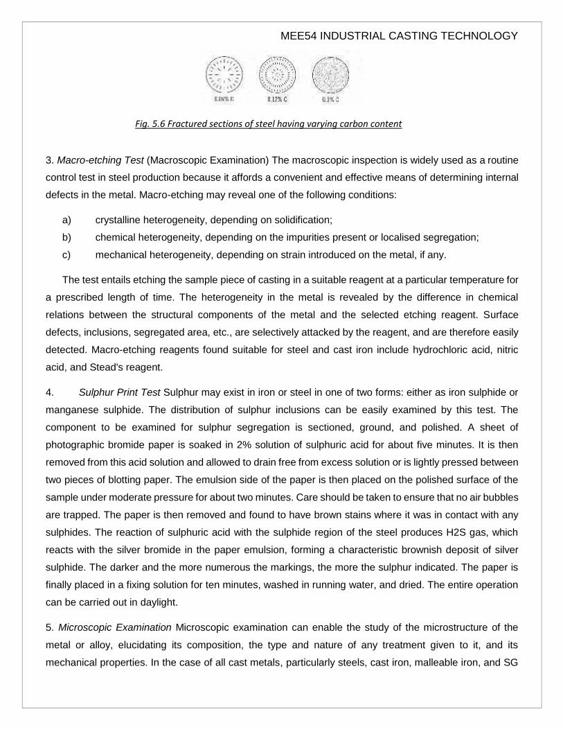
2. Fracture Test By examining a fractured surface of the casting, it is possible to observe coarse graphite,
mottled graphite or chilled portion and also shrinkage cavity, pin hole, etc., The apparent soundness of the
casting can thus be judged by seeing the fracture.
In case of steel casting, fracture test is also used in some foundries to quickly judge the amount of carbon
present. A test rod of 25-mm diameter and 75-mm length is cast in a sand mould and quenched in water.
The rod is then broken into two pieces and the fracture examined visually. Due to quenching, martensite is
formed which is seen in the fractured section in the form of white spots or lines according to the amount of
carbon present. Fig. 5.6 shows three types of fractures for varying amounts of carbon.
MEE54 INDUSTRIAL CASTING TECHNOLOGY
Fig. 5.6 Fractured sections of steel having varying carbon content
3. Macro-etching Test (Macroscopic Examination) The macroscopic inspection is widely used as a routine
control test in steel production because it affords a convenient and effective means of determining internal
defects in the metal. Macro-etching may reveal one of the following conditions:
a) crystalline heterogeneity, depending on solidification;
b) chemical heterogeneity, depending on the impurities present or localised segregation;
c) mechanical heterogeneity, depending on strain introduced on the metal, if any.
The test entails etching the sample piece of casting in a suitable reagent at a particular temperature for
a prescribed length of time. The heterogeneity in the metal is revealed by the difference in chemical
relations between the structural components of the metal and the selected etching reagent. Surface
defects, inclusions, segregated area, etc., are selectively attacked by the reagent, and are therefore easily
detected. Macro-etching reagents found suitable for steel and cast iron include hydrochloric acid, nitric
acid, and Stead's reagent.
4. Sulphur Print Test Sulphur may exist in iron or steel in one of two forms: either as iron sulphide or
manganese sulphide. The distribution of sulphur inclusions can be easily examined by this test. The
component to be examined for sulphur segregation is sectioned, ground, and polished. A sheet of
photographic bromide paper is soaked in 2% solution of sulphuric acid for about five minutes. It is then
removed from this acid solution and allowed to drain free from excess solution or is lightly pressed between
two pieces of blotting paper. The emulsion side of the paper is then placed on the polished surface of the
sample under moderate pressure for about two minutes. Care should be taken to ensure that no air bubbles
are trapped. The paper is then removed and found to have brown stains where it was in contact with any
sulphides. The reaction of sulphuric acid with the sulphide region of the steel produces H2S gas, which
reacts with the silver bromide in the paper emulsion, forming a characteristic brownish deposit of silver
sulphide. The darker and the more numerous the markings, the more the sulphur indicated. The paper is
finally placed in a fixing solution for ten minutes, washed in running water, and dried. The entire operation
can be carried out in daylight.
5. Microscopic Examination Microscopic examination can enable the study of the microstructure of the
metal or alloy, elucidating its composition, the type and nature of any treatment given to it, and its
mechanical properties. In the case of all cast metals, particularly steels, cast iron, malleable iron, and SG

iron, microstructure examination is essential for assessing metallurgical structure and composition.

MEE54 INDUSTRIAL CASTING TECHNOLOGY
The sample for examination is first cut to about 12-mm diameter and 9-mm thickness, and filed and ground
to erase any deep grooves or marks. The piece should not get overheated at any time as this may alter its
structure. The specimen is then polished on a series of emery papers of various grit sizes, the last one
being of the finest variety. Sample polishing machines are available for the purpose. It may sometimes be
desired to mount the sample in Bakelite, epoxy resin, or some plastic material before it is polished so as to
keep edges from getting rounded off. For final polishing, the specimen is rubbed on a special cloth, which
has already been impregnated with a polishing medium. It is then thoroughly cleaned and degreased, by
washing in hot water, and sprayed with acetone or spirit.
The next step is to etch the specimen so that the etching reagent will first dissolve the thin bright layer
produced during polishing and then attack metal at the grain boundaries and make them prominent on the
surface. Owing to the nature of the grain boundaries, the rate of chemical solution along the boundaries
will be greater than within the grains. Therefore, etching will produce the true underlying microstructure.
The specimen is treated with the etching reagent for a few seconds until it acquires a dull matt appearance.
It is then washed in hot water and dried in hot-air blast.
Etching Reagents
For steel and cast irons
(i) nital. (2% solution of nitric acid in alcohol);
(ii) picral. (4% solution of picric acid in alcohol); and
(iii) alkaline sodium picrate (2g of picric acid and 25 g of caustic soda added to 100 ml of water).
For copper and its alloys
(i) ferric chloride solution in water or alcohol; and
(ii) ammonium hydroxide-hydrogen peroxide.
For aluminium and its alloys
(i) hydrofluoric acid solution in water (0.5%);
(ii) sodium hydroxide solution in water (1.0%); and
(iii) sulphuric acid.
After the specimen is etched and washed, it is ready for examination under the metallurgical microscope.
Scanning Electron Microscope The use of a scanning electron microscope (SEM) has brought new insights
in the field of metallurgical analysis, particularly in the study of fractures (fractography), grain size and grain
growth, phase transformations, impurities and trace elements, characteristics of powders and their

MEE54 INDUSTRIAL CASTING TECHNOLOGY
compaction. No specimen preparation is usually necessary. Even non-conducting materials can be
examined by applying a mild conductive coating on the surface. The resolution of SEM being as high as
and the depth of field being nearly 300 times that of an optical microscope, this instrument can be extremely
valuable in quality control of castings, as also other products.
A fine beam of electrons is allowed to interract with the sample. The low-energy secondary electrons are
made to strike a scintillator. The photon image is then fed to a photo multiplier through a light guide. The
signal from the photomultiplier is used to influence the scanning in a cathode ray tube in synchronism with
the scanning of the specimen by the original electron beam. The image on the tube is a magnified view of
the specimen surface with excellent fidelity to topographic details.
POLLUTION CONTROL IN FOUNDRIES
POLLUTANTS IN A FOUNDRY
Foundries are among the industrial plants causing environmental pollution, producing substantial quantities
of air pollutants. The numerous processes available for moulding, melting and casting are accompanied by
evolution of heat, noise, dust and gases. Dust, fines, fly ash, oxides, etc., which form particulate matter are
generated in large quantities when preparing mould and core sands and moulds, melting metals, pouring
moulds, knocking out poured moulds and loading and unloading raw materials. Gaseous matter like gases,
vapours, fumes and smoke are produced during melting and pouring operations. The major pollutants
emitted from various work areas in a foundry are given in Table 9.1. The basic means of controlling the
emission of pollutants are changing the production process, sup plying adequate make-up air, proper
aeration and ventilation of the shop, reduction of pollutants at source by taking appropriate control
measures, dispersion and dilution of pollutants in the air space and good housekeeping.
Major pollutants emitted in a foundry
Work area Pollutant Emission
concentration g/m3
Pattern shop Sawdust, wood chips Heavy
Sand preparation
Dust and fumes, 100-175
powder materials 75-150
Moulding and core-making
Sand 50-100
fumes 100-175
Binder dust 75-150

MEE54 INDUSTRIAL CASTING TECHNOLOGY
Vapours Light
Mould drying and ladle heating CO, so2 Light
Cupola
so2 Light
CO Heavy
Unburnt hydrocarbons. Heavy
smoke
Metallic oxides Moderate
Coke dust 100-175
Limestone dust, fly ash Moderate
Electric arc furnance
Dust, CO, S02 oxides, Moderate
Nitrogen cyanide, fluoride, etc. Light
Electric induction furance Dust, oxides, smoke Light
Pouring and mould cooling
CO Light
Binder fumes Moderate
Oil vapours Heavy
Knock-out
Sand, fines and dust 200-350
Smoke, steam, vapours Heavy
Fettling
Dust, metal dust, sand fumes >100
Abrasive powder 10-50
Heat treatment CO, SO,, oil vapours Light
DUST AND FUME CONTROL
It is of utmost importance that the air polluted by foundry work be cleansed to maintain hygienic working
conditions. The atmosphere in the pattern shop is charged with fine particles of sawdust. Dust sand
particles are exuded when sand is mixed and prepared during moulding, shake-out fettling operations.
Fumes are produced during melting, metal-transfer, and pouring operations. It is essential to devise a
system for collecting all the dust and fumes so produced and disposing them so that they do not pollute

MEE54 INDUSTRIAL CASTING TECHNOLOGY
the atmosphere in the foundry and pose a threat to the health of the workers. When a foundry layout is
planned, provision should be made for dust and fume control. If this vital aspect is attended to as an
afterthought, it becomes difficult to incorporate the necessary equipment.
Materials requiring to be separated may be classified into two broad categories: particulate matter, where
the particles are either solid, such as dust, fume, smoke, and fly ash, or liquid, such as mist and fog; and
gaseous matter, where the contaminant may be either gas over the entire range of atmospheric and
process temperatures and pressures, or liquid at lower temperature, and gas at the temperature and
pressure of its release into the atmosphere.
The method of separation depends on the category to which the pollutant belongs. Some separation
processes are applicable to several types of pollutants whereas others to only one of them. The methods
commonly used in foundries are now outlined.
1. Filter The filter serves for removing particulate matter from gas or air streams by retaining it in or on the
porous structure through which the gas flows (Fig. 5.7.). The porous structure is usually a woven or
felted fabric. The filter must be continuously or periodically cleaned, or replaced.
The filtering action may be obtained in various ways, such as direct interception, impaction, diffusion,
and electrostatic precipitation. In direct interception, the particle is carried by a streamline of gas, which
heads it directly towards a part of the solid surface comprising the filter. In impaction, the particle is in a
streamline of gas, which sweeps by the solid material of the filter and allows the particle to touch the filter
material. In diffusion, a blow from a molecule of the gas projects the particle to the filter surface. In
electrostatic precipitation, electrical charges on the particle and filter attract the particle towards the filter.
One or more high-intensity electrical fields are maintained to cause the particles to acquire an electrical
charge and be forced to move towards the collecting surface.
Filters are commonly employed in pattern shops on various woodworking machines, such as band saw,
circular saw, and sanding machines. They are also used on cupola collection systems in conjunction with
other equipment, such as after-burners, gas cooler, recuperators and exhaust blower. Sand-reclamation
plants also use bag filters for separating 'fines' from sand grains.

MEE54 INDUSTRIAL CASTING TECHNOLOGY
Fig. 5.7 (A) Bag filter (B) Schematic arrangement of an ultra-jet type filter
2. Cyclone The cyclone (Fig. 5.8) works on the principle of Vortex core centrifugal separation in which a
vortex motion of the particulate matter is created within the collector. This motion provides the
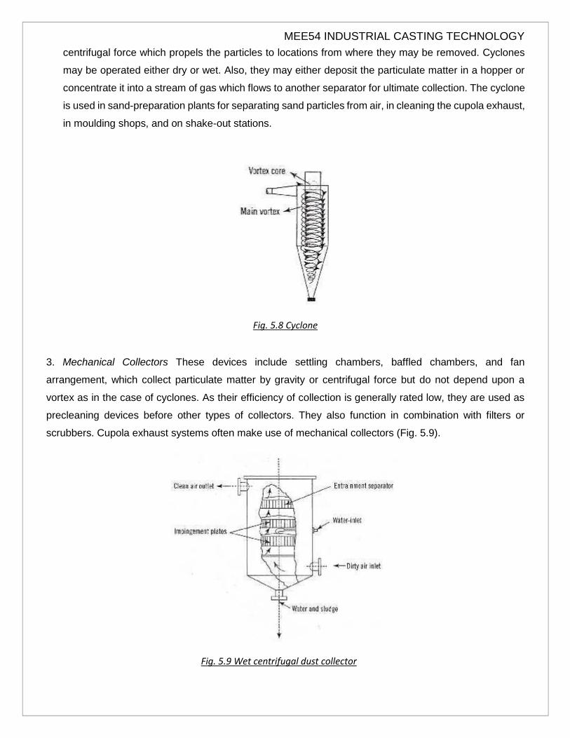
MEE54 INDUSTRIAL CASTING TECHNOLOGY
centrifugal force which propels the particles to locations from where they may be removed. Cyclones
may be operated either dry or wet. Also, they may either deposit the particulate matter in a hopper or
concentrate it into a stream of gas which flows to another separator for ultimate collection. The cyclone
is used in sand-preparation plants for separating sand particles from air, in cleaning the cupola exhaust,
in moulding shops, and on shake-out stations.
Fig. 5.8 Cyclone
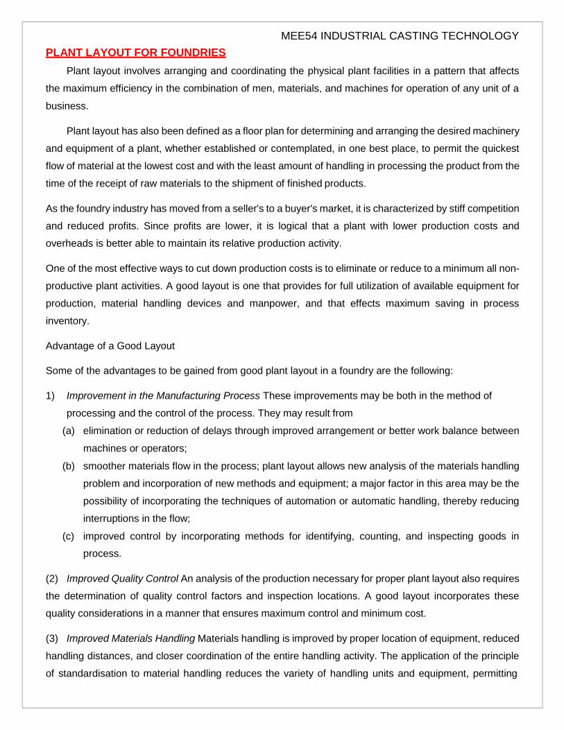
3. Mechanical Collectors These devices include settling chambers, baffled chambers, and fan
arrangement, which collect particulate matter by gravity or centrifugal force but do not depend upon a
vortex as in the case of cyclones. As their efficiency of collection is generally rated low, they are used as
precleaning devices before other types of collectors. They also function in combination with filters or
scrubbers. Cupola exhaust systems often make use of mechanical collectors (Fig. 5.9).
Fig. 5.9 Wet centrifugal dust collector

MEE54 INDUSTRIAL CASTING TECHNOLOGY
4. Scrubbers The scrubber is employed primarily for removing gases and vapour-phase contaminants
from the carrier gas, though it can also remove particulate matter. A liquid, usually water, is introduced
into the collector and it either dissolves or chemically reacts with the contaminant collected. Methods
used to effect a contact between scrubbing liquid and carrier gas includes (i) spraying the liquid into
chambers containing baffles, grille, or packing; (ii) flowing the liquid over weirs; and (iii) bubbling the
gas through tanks or troughs of liquid. Scrubbers are ideal for cleaning the exhausts of cupola and arc
furnaces.
5. After Burners The after-burner assists in oxidising the solid combustible material present in the
particulate matter and converts it into gaseous form. It also helps to convert carbon monoxide into
carbon dioxide as in the case of cupola gases. After-burning may be accomplished by using furnace
oil as a fuel and introducing it along with air into a combustion chamber through which the carrier gas
passes.
6. Combination Devicess Some devices combine features of the aforementioned equipment so that dust
and fumes are controlled most economically and with a minimum pressure drop. For instance, there
are cyclones in which liquid is sprayed, and scrubbers in which cyclonic action is used. Packed-bed
filters, operated wet, and packed-bed scrubbers are similar to each other, the only difference being
that the equipment designed to separate particulate matter is called a filter and the same when
designed to separate gaseous contaminants is called a scrubber. Often, equipment of different types
are used in series. Fig. 5.10 shows a common arrangement of exhaust cleaning used on large-sized
cupolas.
Fig. 5.10 Cupola furnace installation
MEE54 INDUSTRIAL CASTING TECHNOLOGY
PLANT LAYOUT FOR FOUNDRIES
Plant layout involves arranging and coordinating the physical plant facilities in a pattern that affects
the maximum efficiency in the combination of men, materials, and machines for operation of any unit of a
business.
Plant layout has also been defined as a floor plan for determining and arranging the desired machinery
and equipment of a plant, whether established or contemplated, in one best place, to permit the quickest
flow of material at the lowest cost and with the least amount of handling in processing the product from the
time of the receipt of raw materials to the shipment of finished products.
As the foundry industry has moved from a seller's to a buyer's market, it is characterized by stiff competition
and reduced profits. Since profits are lower, it is logical that a plant with lower production costs and
overheads is better able to maintain its relative production activity.
One of the most effective ways to cut down production costs is to eliminate or reduce to a minimum all non-
productive plant activities. A good layout is one that provides for full utilization of available equipment for
production, material handling devices and manpower, and that effects maximum saving in process
inventory.
Advantage of a Good Layout
Some of the advantages to be gained from good plant layout in a foundry are the following:
1) Improvement in the Manufacturing Process These improvements may be both in the method of
processing and the control of the process. They may result from
(a) elimination or reduction of delays through improved arrangement or better work balance between
machines or operators;
(b) smoother materials flow in the process; plant layout allows new analysis of the materials handling
problem and incorporation of new methods and equipment; a major factor in this area may be the
possibility of incorporating the techniques of automation or automatic handling, thereby reducing
interruptions in the flow;
(c) improved control by incorporating methods for identifying, counting, and inspecting goods in
process.
(2) Improved Quality Control An analysis of the production necessary for proper plant layout also requires
the determination of quality control factors and inspection locations. A good layout incorporates these
quality considerations in a manner that ensures maximum control and minimum cost.
(3) Improved Materials Handling Materials handling is improved by proper location of equipment, reduced
handling distances, and closer coordination of the entire handling activity. The application of the principle
of standardisation to material handling reduces the variety of handling units and equipment, permitting

MEE54 INDUSTRIAL CASTING TECHNOLOGY
greater flexibility without sacrificing efficiency. Standardisation may also reduce the investment required for
materials handling.
(4) Minimum Equipment Investment Planned machine balance and location, with minimum handling load
distances, and planned machine loading reduces the inclusion of idle or partially loaded units in production
areas, thereby reducing investment requirements. The reduction of equipment investment applies to
service and maintenance equipment, materials handling equipment, and office equipment, as well as
production machines.
(5) Effective Use of Available Area In many plants, expansion and growth has taken place in such a
manner that plant arrangement has been a matter of immediate convenience. A well-planned plant layout
offers an opportunity to place equipment and services in such a manner that the most effective coordination
is possible. Locating equipment and services such that they can perform multiple functions, development
of up-to-date work areas, and operator job assignment for full utilisation of the labour force, help to improve
utilisation of plant areas.
(6) Improved Utilisation of Labour Proper plant layout allows the design of individual operations, the
process, the flow, and material handling in such a manner that each worker can effectively apply his
activities to the best overall plant effort. Balancing of labour to production needs and machine requirements
eliminates many situations in which the operator's time is not utilised to the maximum. Layout of equipment
for ease of maintenance reduces maintenance personnel requirement. Improved handling, which
frequently means further incorporation of mechanical means, minimises both direct and indirect labour
requirements.
(7) Improved Employee Morale A layout that provides for employee convenience and comfort inevitably
boosts employee morale. A design that incorporates such items as correct lighting, proper cooling and
ventilation, noise and vibration control, sufficient and convenient rest rooms and lunch facilities leads to
efficient job performance and to reduced idle time, otherwise spent in travelling to facilities or in grievance
actions that result from dissatisfaction.
(8) Improved Efficiency in Plant Services Efficiency is obtained by considering the problems of
maintenance and service equipment and buildings during the arrangement and layout planning. New utility
distribution systems giving maximum flexibility and capacity become an integral part of the new layout,
thereby facilitating future re-arrangement or expansion.
Steps in Planning a Foundry Layout
In order to realise the maximum potential of a layout for a new foundry, a systematic procedure must be
followed. The final layout can be no better than the data upon which it is based. Certain steps if followed
assure the collection and analysis of the necessary supporting data.

MEE54 INDUSTRIAL CASTING TECHNOLOGY
1) Analyse the Product to be Manufactured This implies having available or deciding
(a) the annual tonnage;
(b) the type of castings to be produced: their range of sizes, weights, composition, and product mix;
and
(c) the maximum piece weight.
(2) Determine the Process Required to Manufacture the Product Operation sheets must be prepared or
developed for each manufactured product. For layout purposes, only the sequence of operations is required
initially.
Castings may be classified as light, medium, and heavy or according to the quantity required. Logical
location of workplaces like moulding, core-making, melting, inspection, etc., should be suitably determined.
Green sand, skin dried, dry sand, machine moulding, shell moulding, CO, process, etc., are among the
various processes to be broadly considered first to suit the casting requirements before the details of layout
are decided.
(3) Prepare Layout Planning Charts The layout planning chart is of prime importance as it serves as the
medium for first tabulating and then combining the various factors to be provided for in the final layout. It
incorporates
a) the flow process showing all operations, movements, storages, and inspections in sequence;
b) standard times for each operation obtained from time studies or predetermined time standards;
c) machine selection;
d) machine balance;
e) manpower requirements; and
f) materials handling load, method, and equipment requirements.
To complete the layout planning chart, a full review and analysis is required at each step. Once this is done,
the layout of the manufacturing area involves primarily a conversion of the layout planning chart data to the
physical plant statistics. To achieve this, three additional jobs require attention:
(4) Determine Work Stations The requirements of machine, operator, materials, and service areas must
be considered. This is accomplished by using man-machine and/or operation charts and scaled workstation
sketches/models.
(5) Analyse Storage Area Requirements Before beginning the actual layout both the size and the location
of the storage area should be studied with relation to production activities. At least three types of storage
should be included in the survey:
(i) storage of raw-materials;
(ii) in-process storage; and
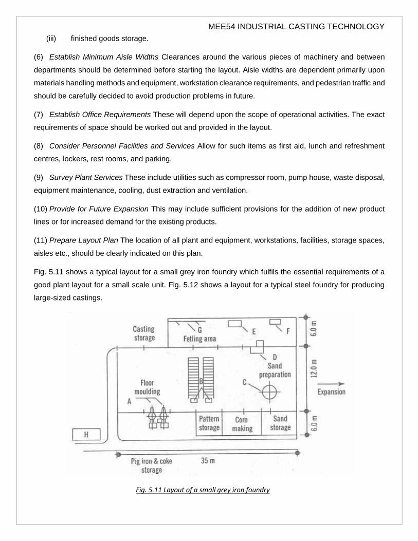
MEE54 INDUSTRIAL CASTING TECHNOLOGY
(iii) finished goods storage.
(6) Establish Minimum Aisle Widths Clearances around the various pieces of machinery and between
departments should be determined before starting the layout. Aisle widths are dependent primarily upon
materials handling methods and equipment, workstation clearance requirements, and pedestrian traffic and
should be carefully decided to avoid production problems in future.
(7) Establish Office Requirements These will depend upon the scope of operational activities. The exact
requirements of space should be worked out and provided in the layout.
(8) Consider Personnel Facilities and Services Allow for such items as first aid, lunch and refreshment
centres, lockers, rest rooms, and parking.
(9) Survey Plant Services These include utilities such as compressor room, pump house, waste disposal,
equipment maintenance, cooling, dust extraction and ventilation.
(10) Provide for Future Expansion This may include sufficient provisions for the addition of new product
lines or for increased demand for the existing products.
(11) Prepare Layout Plan The location of all plant and equipment, workstations, facilities, storage spaces,
aisles etc., should be clearly indicated on this plan.
Fig. 5.11 shows a typical layout for a small grey iron foundry which fulfils the essential requirements of a
good plant layout for a small scale unit. Fig. 5.12 shows a layout for a typical steel foundry for producing
large-sized castings.
Fig. 5.11 Layout of a small grey iron foundry

MEE54 INDUSTRIAL CASTING TECHNOLOGY
Fig. 5.12 Typical Layout of a grey iron foundry
AREAS FOR MECHANISATION
Mechanisation has a distinct impact on areas concerned with the preparation and control of sand;
moulding and core-making; melting, pouring, and shake-out operations and material handling.
Sand Preparation and Control, Moulding and Core-Making
Sand preparation equipment is invaluable in both jobbing and mass-production foundries. The riddle
which rids sand of refuse, the muller which kneads the sand for re-use, the magnetic separator which
removes iron particles from return sand, the aerator which helps to improve the flowability of sand, hoppers
which act as storage for sand before it is sent for mulling, all such equipment are essential for maintaining
the homogeneity of sand mixtures. If sand is initially wet, it has to be dried in sand driers. In case the sand
gets overheated in the mould, it has to be cooled down to room temperature in special coolers, before it
can be re-used.
Continuous Mixer Continuous mixers (Fig. 5.13) are now coming increasingly into use with the development
of organic no-bake resin systems based on phenolic binders. These two-part no-bake systems are fast-
acting, need less sand, generate low nitrogen, give high productivity and the sands are reclaimed easily.
Two types of mixers are used—pivotal type for small to medium sizes, and the mobile type for heavy jobs.

MEE54 INDUSTRIAL CASTING TECHNOLOGY
Fig. 5.13 Continuous mixer unit
The mixer consists of a horizontal trough fixed to a column at one end with a rotating shaft with blades
around fastened to it. The sand along with resin and hardener are introduced at one end in the trough in
measured quantities using a pneumatic metering device. As the constituents travel in the trough from one
end to the other, they get thoroughly mixed and the sand grains are uniformly coated with resin. The sand
mix is finally discharged from a spout directly into the moulding box placed below on a compaction table.
The sand is compacted by means of low amplitude and high-frequency vibrations caused to the table using
two unbalanced motors. The moulds are then painted, cores laid in place, closed and poured. The poured
moulds after cooling down are transferred on a conveyer line to the shake-out and reclamation.
Integrated systems, now available, consist of a sand-preparation unit supplying mixed resin sand
continuously, discharging it into a moulding box placed on a vibratory compaction table, a pattern loop-
mould stripping device, and a shake-out with a reclamation plant (Fig. 5.14) The reclamation unit consists
of a fluidised sand cooler cum classifier which allows about 80-90% of the used sand to be reclaimed and
re-used, thus affecting considerable savings in sand costs. The castings are removed from the mould, the
sand lumps are reduced to grain size in a scrubber and oversized grains, lumps, tramp metal and other
degradable material along with sand fines are separated. The dust is removed using a bag filter- type dust-
extractor unit. The sand is cooled in a cooler unit using cooling water circulating through copper tubes
placed in the fluidised bed. The water is cooled continuously in an evaporative type water-cooling tower.
The reclaimed sand is conveyed pneumatically to the mixer unit. The new sand is added to reclaimed sand
in the desired proportion by adjusting a pneumatic slide-gate valve.

MEE54 INDUSTRIAL CASTING TECHNOLOGY
Fig. 5.14 Reclaimer unit
Thus, the use of a continuous mixer enables the quality of castings produced to be much higher than those
produced by the CO, process. Also, sand and fettling costs are reduced and labour productivity is greatly
increased.
Sand-testing facilities are essential for controlling the characteristics affecting the properties of moulds and
cores. The conventional approach to sand control in foundries is to maintain a constant, predetermined
moisture level. At constant moisture, however, there is no regulation of the variation in the composition and
temperature of sand, in the nature or the amount of additives, all of which affect the working and ramming
properties of sand. Consequently, improved methods of sand control have come into vogue. In one method,
sand is prepared to a constant degree of mouldability. The apparatus, called the mouldability controller
(Fig. 5.15), adjusts the moisture addition to compensate for the variations in sand composition.
Fig. 5.15 Mouldability Controller
The mouldability controller has a slotted vibratory feeder trough and a system of photoelectric cells.
The controller is positioned at the sand mixer from where a small amount of sand enters the controller. The
sand falls on to the vibratory feeder and moves towards the slots. When the sand is dry, it falls through the

slots and blocks off the focusing apertures through which two light sources are directed towards two

MEE54 INDUSTRIAL CASTING TECHNOLOGY
photocells. The interruption of these light beams opens two water valves in the mixer to add more moisture
to the sand. When the required amount of water has been received by the sand and the desired mouldability
level attained, sand moving on the vibratory feeder tends to bridge the slots rather than fall through them.
It, therefore, no longer obstructs the light beams, and so the water valves get closed. This system of
adjusting water additions by the opening and closing of water valves operates continually according to the
requirements of the sand and thus maintains a constant workability, producing moulds of an exceptionally
high quality.
Melting, Pouring and Shake-out Equipment
In a mechanized foundry, the attempt is to substitute manual labour by mechanical devices wherever
possible. However, the extent to which the machine can be exploited is dependent on factors such as the
type and condition of equipment, the economical feasibility of installing such devices, and the floor space
available. Although the mechanical gear varies from foundry to foundry, it generally includes a crane, lift
truck, turnover truck, belt conveyer, or bucket conveyer system for handling charges, such as pig iron,
scrap, and coke and flux, and transporting to the furnace.
Machines are also essential for sending the charge up to the charging door, as in the cupola, and
discharging it into the furnace. A skip-hoist type of conveyor is customarily used to send the charge-up. In
this arrangement, the charging bucket is mounted on wheels, and guided by a vertical or inclined track.
The bucket is raised and lowered along the track by the working of a reversible electric motor through a
cable. When the bucket reaches the charging door, it operates an electrical limit switch which brakes the
motor instantly and, after some time lag, reverses it. For convenient loading, the bucket is lowered into a
pit. The discharge bucket used is usually the top-discharge type which is automatically inverted as it enters
the charging door of the cupola.
For large-sized cupolas, the crane type of conveyance is suitable. Here, the bucket is raised by a crane
from the loading station and carried horizontally into the charging door. The bottom of the discharge bucket
has a hinged door which swings open for discharging.
In the case of other furnaces, such as the open-hearth furnace, air furnace, and electric furnace, the crane
arrangement with either the top discharge or the bottom discharge bucket is commonly employed.
The variety of equipment used for melting the metals has already been discussed in Chapter 6. Factors
such as the metal to be melted, the quantity of metal required, the quality and purity of metal desired, and
the availability of fuel determine the type of equipment needed in the foundry shop.
After the metal is melted, it is scooped into ladles and carried to the pouring floor by means of a crane. The
metal may be poured either by keeping the ladle stationary in the crane and moving the moulds one after

MEE54 INDUSTRIAL CASTING TECHNOLOGY
another on a roller conveyer or by keeping the moulds fixed in a line and shifting the ladle forward every
time a mould is filled with the metal.
When the castings are sufficiently cool, the moulds are transported by a crane or conveyer to the shake-
out station where they are vibrated or shaken in such a way that the castings along with the sand are eased
out of the moulding boxes. The shaking operation is conducted on a grating which has a sand conveyer
beneath. The sand duly separated from the castings passes through the grate and is carried away to a
sand-reclamation plant whereas the castings and the emptied moulding boxes remain on the grating. The
castings are then sent to the fettling and inspection shop and the moulding boxes are returned to the
moulding section.
Shake-out machines are of many types. For small-sized moulds, a stationary grating installed at a small
incline is most suitable. The moulds break, when jolted and dropped, allowing the sand to pass through the
grating and leaving the casting and the moulding box above it. For small- and medium-sized castings, the
vibrating type of shake-out is commonly used. It consists of a perforated plate or a heavy grille fastened to
a vibrating frame. After the mould is placed on the grille, the frame is vibrated by means of a motor-driven
eccentric arrangement to extract the sand from the mould and release it through the grille. The vibrating
frame is connected to the machine structure by compression springs, thus largely eliminating the
transmission of vibrations into the foundation.
For heavy moulds, the ideal shake-out is the bumper type. The mould is positioned on two heavy beams
which are hinged at one end. The free ends of the beams rest on motor-driven cams. When the cams are
rotated, the beams get first lifted slightly, then dropped back into place. This action jolts the mould. All
shake- outs should be fitted with a hood and a powerful dust-suction device to prevent fine sand and dust
particles from escaping into the air around.
Automatic Pouring System During the last ten years, several foundries in the country have installed
automatic pouring systems as an adjunct to large-capacity induction furnaces with the objective of
maintaining consistent quality of castings produced, and for controlling pouring rate and pouring time of
molten metal and reducing metal losses. This has reduced manpower requirements considerably,
improving yield of the castings and productivity of the foundry, and, further, the quality of work life. These
systems are well-suited in innovative and quality- oriented foundries engaged in large-scale mass
production or continuous type of production of gray and ductile iron castings using automatic moulding
lines.
Their success is leading the way for more widespread adoption of this modern technology. Thus, increased
casting production, higher casting quality and enhanced worker safety is made possible by applying
automatic pouring technology. The pouring system uses a high response stopper-rod pouring mechanism
and a vision-based control technology, which can allow precise pours mould-after- mould, without any

MEE54 INDUSTRIAL CASTING TECHNOLOGY
operator intervention or interruption. Ladles bring hot metal from the furnaces at carefully timed intervals to
maintain the desired pouring temperature range in the pouring tundish. Automatic pouring continues as the
tundish is replenished.
The moulding lines are so arranged that perfectly filled moulds move from the automatic pouring system
along the now-empty manual pouring line. Apart from the advantages enumerated above, other savings
and efficiencies are obtained in several other areas, such as reduced maintenance requirements, improved
working environment, commitment to quality and productivity and finally rapid payback of capital
expenditure.
MATERIAL HANDLING
Material handling equipment is an invaluable asset in the rapid and economic production of castings on a
large-scale. The foundry which is the receiving centre of huge quantities of diverse materials, requires to
be suitably equipped to ensure efficient handling and treatment of items, such as
1) sand;
2) moulds and cores;
3) molten metal; and
4) castings.
1) Handling Sands Sands are required to be conveyed from one part of the production foundry to another
for various purposes. For example, sand is taken from the shake-out station to the riddle for screening;
from the screen to the magnetic separator; from the magnetic separator to the reconditioning plant, i.e.,
muller and aerator or to the hoppers for storage; and from the storage to the mixing or conditioning
plant. Reconditioned sand has to be sent to distribution mains and then to workstations. All this
travelling to and fro is conducted on a sand conveyer. The wide range of sand conveyers covers
specified areas of work in the foundry shop.
(i) Belt Conveyer The belt conveyer is commonly used for transferring sand from one place to
another in travel that requires a horizontal or an inclined direction of movement. It consists of
an endless belt, two pulleys (called head and tail pulleys), rollers or idlers for carrying the loaded
belt and returning the empty belt, a belt-tightening mechanism, and bell cleaners. The belts are
available in various sizes and strengths and are made of cotton plies bonded with synthetic
rubber. Since such material cannot withstand more than about 150°C, the belt conveyer can be
used only when the temperature of the sand is within the limit. Where hot sand is to be
transported, a metal conveyer is used.
The head pulley is used for driving the belt and is connected to an electric motor through
reduction gear. Its diameter should be large enough to ensure full traction. To prevent sand
from spilling and to keep it in the centre, the idlers which support the belt are arranged in three

MEE54 INDUSTRIAL CASTING TECHNOLOGY
pieces, i.e., each set of idlers has three rollers, one horizontal in the centre and two slightly
inclined on the sides. These idlers should not be spaced very far apart, otherwise the belt will
sag too much under load. When the sand conveyer is used for inclined travel, the angle of incline
should not exceed 15° for dry and 25° for tempered sand to keep it from rolling backwards.
(ii) Bucket Elevator When the sand is to be conveyed vertically upwards, a bucket elevator is ideal.
There are two pulleys, one at the top and the other at the bottom which carry an endless belt.
The belt carries a number of buckets all around and the whole assembly is enclosed in a steel
casing which has two openings, one at the bottom for feeding and the other at the top for
discharge. The bucket elevator is generally preferred to the inclined belt conveyer owing to a
saving in space and cost.
(iii) Apron Conveyer The apron conveyer's overlapping steel plates, hinged at the ends, serve, when
assembled, the same purpose as a belt. The advantage of an apron conveyer is that it can be
used for transporting materials that are too hot to be carried by a belt. The drawbacks are that
it cannot be used at high speeds, there are chances of sand spillage and leakage through the
plates, and the cost of maintenance as well as the initial costs are higher.
(iv) Flight Conveyer The flight conveyer is generally used for distributing sand to workstations from
an overhead trough. It has two endless chains moving on sprockets, fixed at both ends, and
carrying steel plates, called 'flights', at certain intervals. When the chain moves, it causes the
flights to shift in the trough and force the sand to enter the openings in the hoppers.
(v) Reciprocating and Oscillating Conveyer Occasionally, the reciprocating and oscillating
conveyers are also considered suitable for transporting sand. The reciprocating action is
produced by a crank-pin and connecting-rod arrangement. This type of conveyer is used for
short travels where the depth of excavation needed for continuous conveyance is not a requisite.
The oscillating conveyer is also sometimes selected for transporting hot sand and hot castings.
It is made of steel plates which are fastened together and secured by two beams. The oscillating
action is produced by means of an eccentric.
(vi) Mono-rail Conveyer The mono-rail conveyer is frequently used for carrying sand and other
items, such as castings, molten metal, and furnace charge. The sand is filled in buckets or
containers of the drop-bottom type and transported from one place to another on an overhead
mono-rail. The conveyer may be either manually or electrically operated.
(vii) Crane For small foundries engaged in jobbing work, an overhead travelling crane may be more
convenient for carrying sand. The sand is filled in a bottom discharge type of bucket which is
transferred with the help of a crane.
2) Handling Moulds In a production foundry, moulds may be conveyed from the mould-production section
to the storage where they remain stationary for pouring or they may be conveyed past a pouring station
where molten metal is poured into them while they are in motion. The moulds when cool are conveyed
MEE54 INDUSTRIAL CASTING TECHNOLOGY
to a shake- out station and, after shake-out operation, the emptied flasks, moulding boards, etc., are
returned to the mould-production area. All these transport operations in a mechanised foundry are
conducted on a suitable conveyer system.
Like sand conveyers, mould conveyers also are of many types, each suited to particular working
conditions.
(i) Roller Conveyer The roller conveyer has two beams fixed on trestles of suitable height and
supporting laterally arranged rollers above. It may be either of the gravity or the power-driven type.
Gravity conveyers are those in which no power is used to drive the rollers and move the moulds.
Instead, the ends of the rollers are fitted in sealed bearings and the moulds need to be pushed by
the operator to cause them to move on the rollers. The beams may be fixed at a slight incline to
facilitate the moulds' movement by the force of gravity.
In the case of power-driven conveyers, some of the rollers at fixed intervals along the length
of the conveyer are driven by an electric motor which has a variable speed to enable coordination
of the mould movement with mould-production. This type of conveyer is expensive and is,
therefore, considered worthwhile only for mass-production foundries whereas the gravity conveyer
is suitable for both jobbing and mass-production foundries.
(ii) Pallet (Car- Type) Conveyer The pallet or car-type conveyer is the most efficient means of moving
moulds in large-scale foundries from the mould-production area to the pouring department and
after allowing adequate time for cooling, to the shake-out station. It has pallets made for cast iron
or steel plates mounted on wheels which can roll along a narrow gauge track. The moulds are
placed on the pallets and pushed manually. In the case of continuous drives, however, the pallets
may be connected by a chain and driven from one end by power. Pallet conveyers have made
completely mechanised work possible.
(iii) Overhead Conveyer Sometimes an overhead conveyer of the mono-rail type is also employed for
transporting moulds in small foundries. The completed moulds are placed on the platform of the
conveyer and the platform is carried to the pouring area by an overhead mono-rail. After the casting
has solidified, the same carrier is moved to the shake-out station.
3) Handling Molten Metal For pouring molten metal into moulds, two systems are commonly followed.
Where a continuous conveyer is not used, the moulds after completion are carried on a roller conveyer
to the storage area. The molten metal is transferred in ladles to this area with the help of a traveling
crane or hoist and is poured into the stored moulds. Where the moulds are constantly moving, the metal
is brought on a mono-rail conveyer and poured into the moving moulds.
4) Handling Castings After the castings are removed from the moulds at the shake-out station, they are
transported on a suitable conveyer to the clearing and fettling section. The range of conveyers includes
the plate-band, roller, oscillating and overhead varieties.

MEE54 INDUSTRIAL CASTING TECHNOLOGY
(i) Plate-band Conveyer A plate-band conveyer is used in many foundries for
carrying castings to the fettling or inspection sections. It is excellent for both
horizontal and inclined travels and for short as well as long distances. The plates
are joined together and mounted on a continuous chain moving on power-driven
sprockets.
(ii) Roller Conveyer The roller conveyer can carry castings in the same way as it
carries moulds. The gravity type is particularly cheap to install, and satisfies the
need of small foundries.
(iii) Oscillating Conveyer The oscillating conveyer, which is the frequent choice for
sands, is sparingly used for transferring castings.
(iv) Overhead Conveyer The overhead conveyer is considered suitable for carrying
castings from the shake-out station to the shot-blasting rooms for cleaning. It
carries the castings by means of hooks suspended from a chain. The conveyer
along with the castings enters the shot-blasting chamber from one side and
leaves it through the exit on the rear side.
(v) Industrial Trucks Lift trucks and front-end loaders are in use in foundaries for
decades. For industrial trucks, a careful evaluation of the factors that limit their
efficiency can help in improving the foundry productivity. It can also help to
evaluate the function of trucks in the planning of overall materials handling,
involving cranes, monorail carriers and belt conveyers, which may lead to saving
in time and manufacturing costs.
(vi) Robots Several operations in a foundry shop are assumed to be hazardous,
unpleasant, suffocating, tiring and unattractive to workers. Robots are most
suitable to operate in such locations to enhance productivity, quality and to
decrease manufacturing cost of the operations, which are repetitive in nature
requiring consistency in quality and quantity of production. A robot, being a
programmable device, is capable of performing complex actions in a wide
variety of operations without human intervention.