Embed Size (px)
Citation preview
Unit III– Theory of columns
Dr.P.Venkateswara Rao, Associate Professor, Dept. of Civil Engg., SVCE, Sriperumbudir
1
Dr.P.Venkateswara Rao, Associate Professor, Dept. of Civil Engg., SVCE, Sriperumbudir
2
Unit III – Theory of Columns
• References:
Punmia B.C.,"Theory of Structures" (SMTS) Vol II, Laxmi Publishing Pvt Ltd, New Delhi 2004.
Rattan.S.S., "Strength of Materials", Tata McGraw Hill Education Pvt. Ltd., New Delhi, 2011.
Rajput R.K., "Strength of Materials (Mechanics of Solids)", S.Chand & company Ltd., New Delhi, 2010.
Ramamrutham S., “Theory of structures” Dhanpat Rai & Sons, New Delhi 1990.
Columns
• Columns are compression members.
• There are various examples of members subjected to compressive loads.
• Post is a general term applied to a compression member.
• Strut is a compression member whose lateral dimensions are small compared to it’s length.
• A strut may be horizontal, inclined or vertical and this term is used in trusses. (Tie is a tension member in a truss)
• But a vertical strut, used in buildings or frames is called column.
• Columns, pillars and stanchions are vertical members used in building frames.
Dr.P.Venkateswara Rao, Associate Professor, Dept. of Civil Engg., SVCE, Sriperumbudir
3
Various names of compression members as per application:
Classification of Columns
• 1.Short column: Short column fails by crushing (compressive yielding) of the material.
• 2. Long column: Long column fails by buckling or bending. ( geometric or configuration failure)
• 3. Intermediate column: Intermediate column fails by combined buckling and crushing. (failure due to both material crushing and geometrical instability)
Dr.P.Venkateswara Rao, Associate Professor, Dept. of Civil Engg., SVCE, Sriperumbudir
4
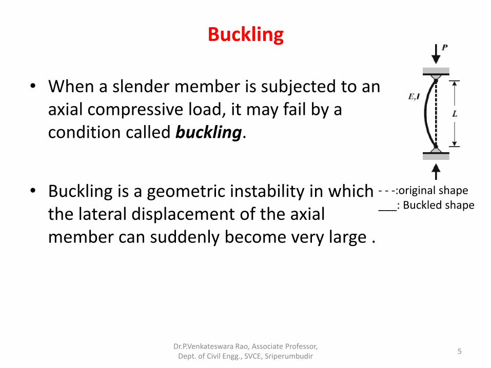
Buckling
• When a slender member is subjected to an axial compressive load, it may fail by a condition called buckling.
• Buckling is a geometric instability in which the lateral displacement of the axial member can suddenly become very large .
- - -:original shape ___: Buckled shape
Dr.P.Venkateswara Rao, Associate Professor, Dept. of Civil Engg., SVCE, Sriperumbudir
5
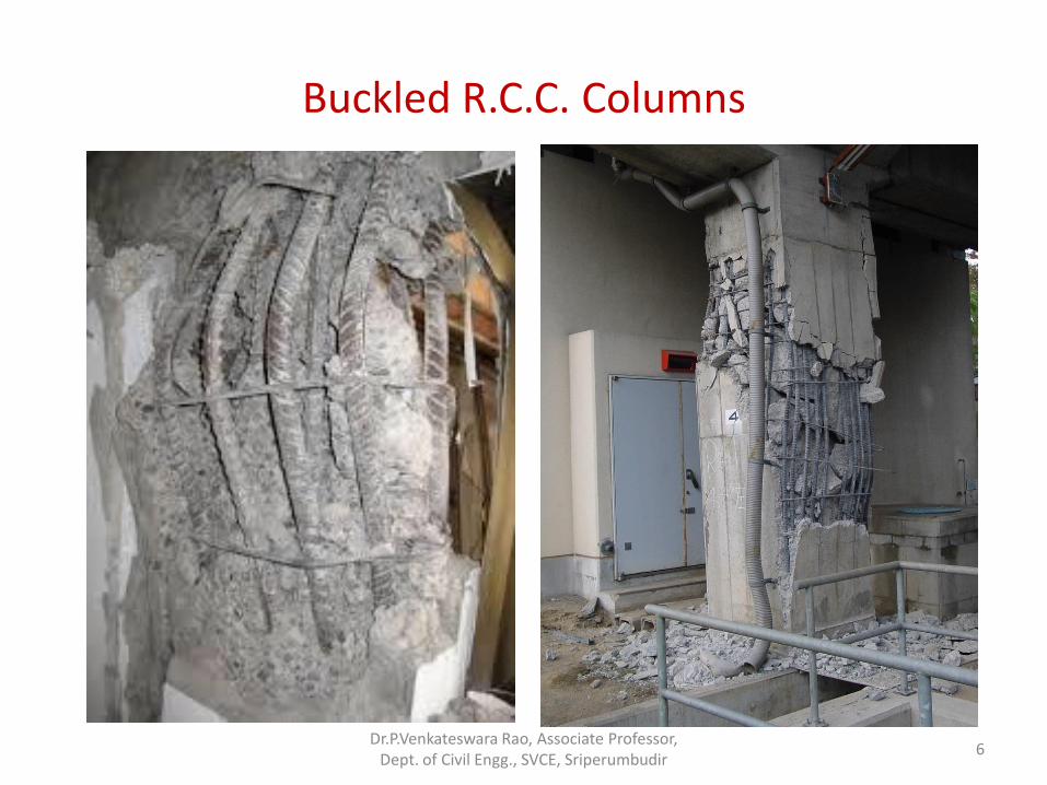
Buckled R.C.C. Columns
Dr.P.Venkateswara Rao, Associate Professor, Dept. of Civil Engg., SVCE, Sriperumbudir
6
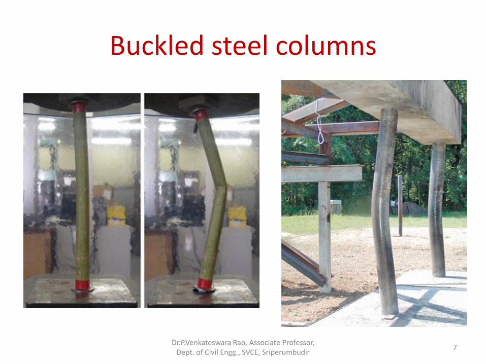
Buckled steel columns
Dr.P.Venkateswara Rao, Associate Professor, Dept. of Civil Engg., SVCE, Sriperumbudir
7
Buckling examples of structural members
• 1. Building columns that transfer loads to the ground
•
• 2. Truss members in compression
• 3. Machine elements
• 4. Submarine hulls subjected to water pressure
Dr.P.Venkateswara Rao, Associate Professor, Dept. of Civil Engg., SVCE, Sriperumbudir
8
Equilibrium States
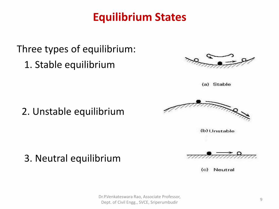
Three types of equilibrium:
1. Stable equilibrium
2. Unstable equilibrium
3. Neutral equilibrium
Dr.P.Venkateswara Rao, Associate Professor, Dept. of Civil Engg., SVCE, Sriperumbudir
9
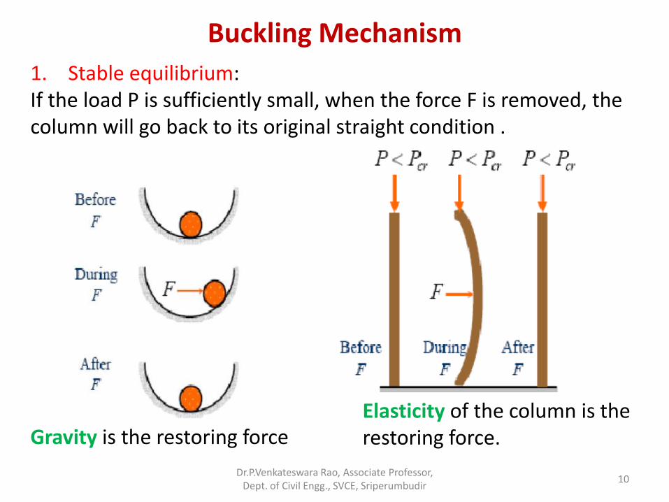
Buckling Mechanism
1. Stable equilibrium: If the load P is sufficiently small, when the force F is removed, the column will go back to its original straight condition .
Elasticity of the column is the restoring force. Gravity is the restoring force
Dr.P.Venkateswara Rao, Associate Professor, Dept. of Civil Engg., SVCE, Sriperumbudir
10
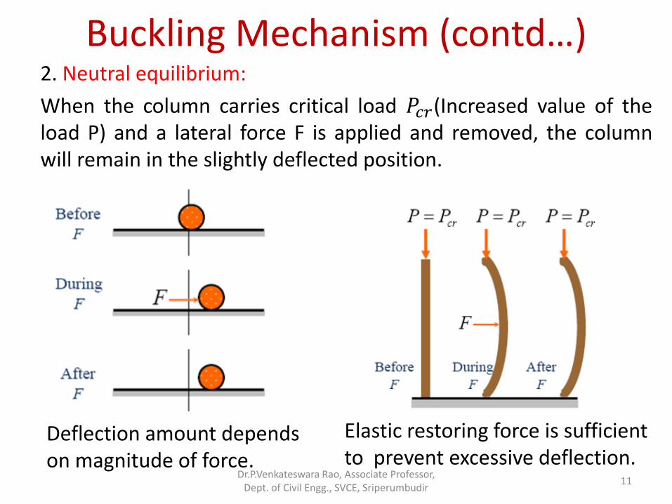
Buckling Mechanism (contd…) 2. Neutral equilibrium:
When the column carries critical load 𝑃𝑐𝑟(Increased value of the load P) and a lateral force F is applied and removed, the column will remain in the slightly deflected position.
Elastic restoring force is sufficient to prevent excessive deflection.
Deflection amount depends on magnitude of force.
Dr.P.Venkateswara Rao, Associate Professor, Dept. of Civil Engg., SVCE, Sriperumbudir
11
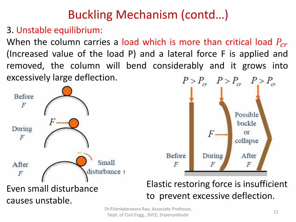
Buckling Mechanism (contd…) 3. Unstable equilibrium: When the column carries a load which is more than critical load 𝑃𝑐𝑟 (Increased value of the load P) and a lateral force F is applied and removed, the column will bend considerably and it grows into excessively large deflection.
Elastic restoring force is insufficient to prevent excessive deflection.
Even small disturbance causes unstable.
Dr.P.Venkateswara Rao, Associate Professor, Dept. of Civil Engg., SVCE, Sriperumbudir
12
Buckling Mechanism (contd…)
• Conclusion:
Depending on the magnitude of force P, either column remains in straight position or in slight bent position or collapse due to crack extension.
Dr.P.Venkateswara Rao, Associate Professor, Dept. of Civil Engg., SVCE, Sriperumbudir
13
Euler’s long column theory
• The direct stress 𝑓0 due to direct load is very small compared to bending stress 𝑓𝑏 due to buckling in long column.
• Euler derived an equation, for the buckling load of long column based on bending stress (neglecting the effect of direct stress).
• Buckling load cannot be used in short column.
Dr.P.Venkateswara Rao, Associate Professor, Dept. of Civil Engg., SVCE, Sriperumbudir
14
Assumptions in the Euler’s theory
1. The column is initially straight.
2. The cross section is uniform throughout.
3. The ends of the column are frictionless.
4. The material is homogeneous and isotropic.
5. The self weight of the column is neglected.
6. The line of thrust coincides exactly with the axis of the column.
7. The shortening of column due to axial compression is negligible.
8. The column failure occurs due to buckling only.
Dr.P.Venkateswara Rao, Associate Professor,
Dept. of Civil Engg., SVCE, Sriperumbudir 15
Cases of long columns based on end conditions
• 1. Both end pinned
• 2. Both ends fixed
• 3. One end fixed and the other end pinned
• 4. One end fixed and the other end free
Dr.P.Venkateswara Rao, Associate Professor, Dept. of Civil Engg., SVCE, Sriperumbudir
16
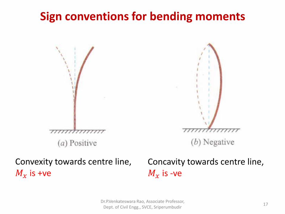
Sign conventions for bending moments
Convexity towards centre line, 𝑀𝑥 is +ve
Concavity towards centre line, 𝑀𝑥 is -ve
Dr.P.Venkateswara Rao, Associate Professor, Dept. of Civil Engg., SVCE, Sriperumbudir
17
End conditions of column
• Three important end conditions based on support types.
• (i) Pinned end: End is fixed in position only. ∴ Deflection, 𝑦 = 0.
• (ii) Fixed end: End is fixed in position and direction.
∴ Deflection 𝑦 = 0 and slope, 𝑑𝑦
𝑑𝑥= 0.
• (iii) Free end: Neither fixed in position nor in direction.
Dr.P.Venkateswara Rao, Associate Professor, Dept. of Civil Engg., SVCE, Sriperumbudir
18
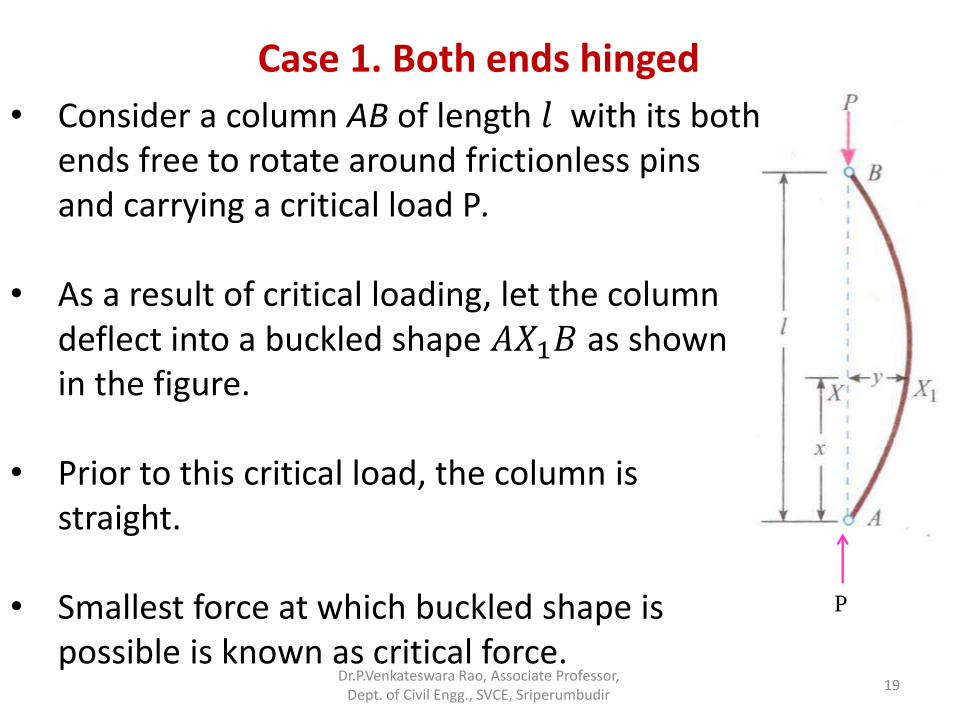
Case 1. Both ends hinged
P
• Consider a column AB of length 𝑙 with its both ends free to rotate around frictionless pins and carrying a critical load P.
• As a result of critical loading, let the column
deflect into a buckled shape 𝐴𝑋1𝐵 as shown in the figure.
• Prior to this critical load, the column is straight.
• Smallest force at which buckled shape is possible is known as critical force.
Dr.P.Venkateswara Rao, Associate Professor, Dept. of Civil Engg., SVCE, Sriperumbudir
19
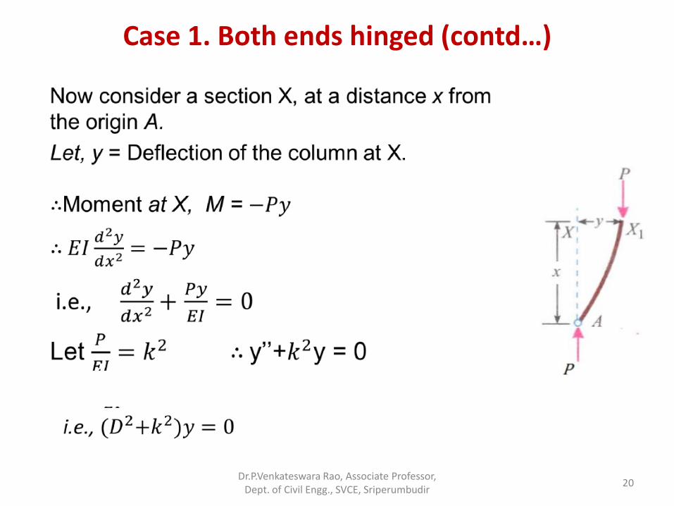
Case 1. Both ends hinged (contd…)
Dr.P.Venkateswara Rao, Associate Professor, Dept. of Civil Engg., SVCE, Sriperumbudir
20
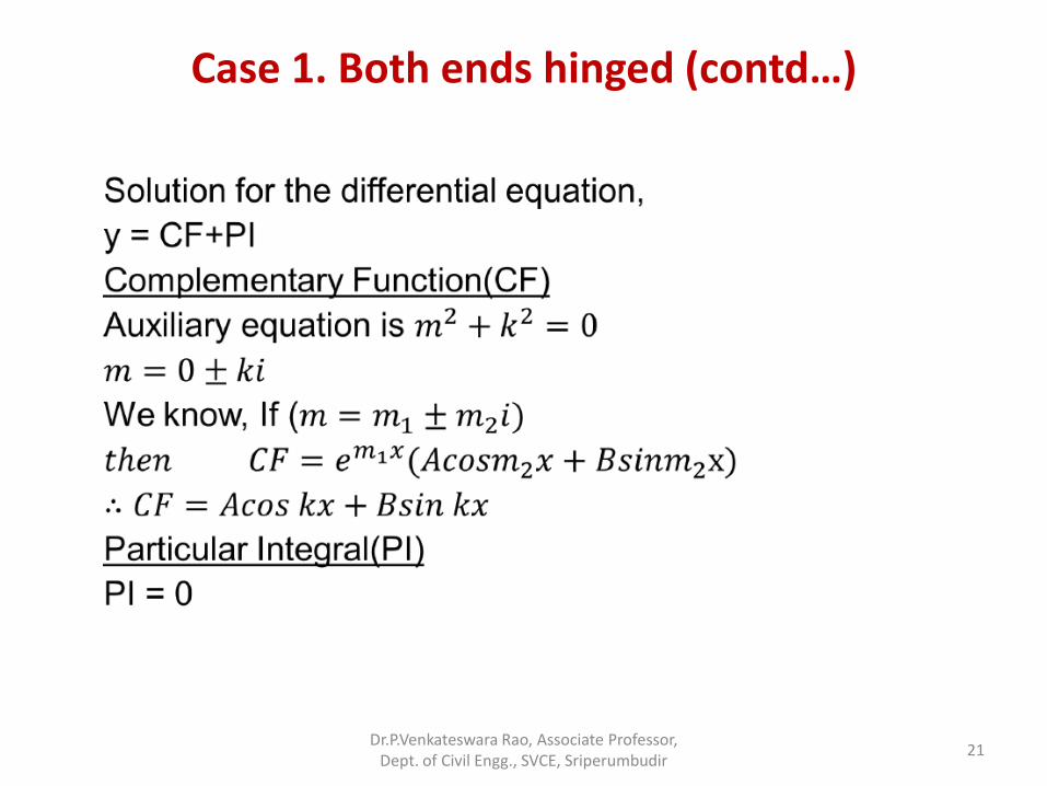
Case 1. Both ends hinged (contd…)
Dr.P.Venkateswara Rao, Associate Professor, Dept. of Civil Engg., SVCE, Sriperumbudir
21
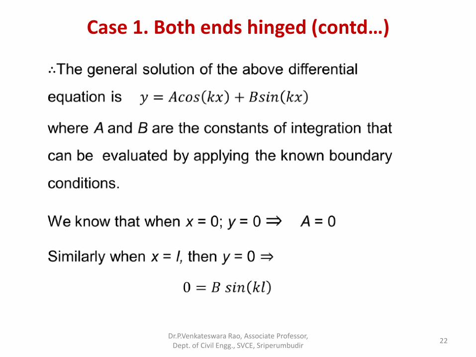
Case 1. Both ends hinged (contd…)
Dr.P.Venkateswara Rao, Associate Professor, Dept. of Civil Engg., SVCE, Sriperumbudir
22
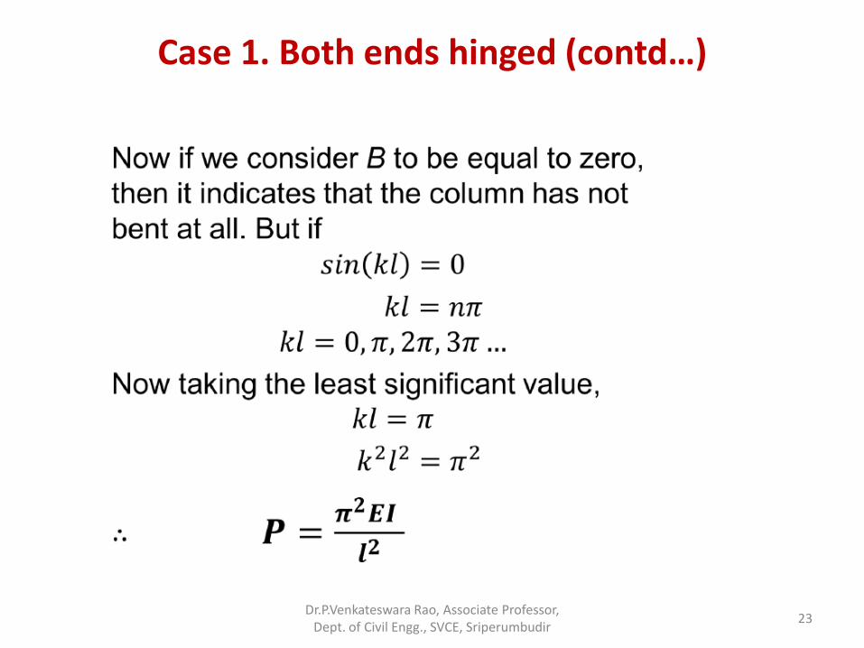
Case 1. Both ends hinged (contd…)
Dr.P.Venkateswara Rao, Associate Professor, Dept. of Civil Engg., SVCE, Sriperumbudir
23
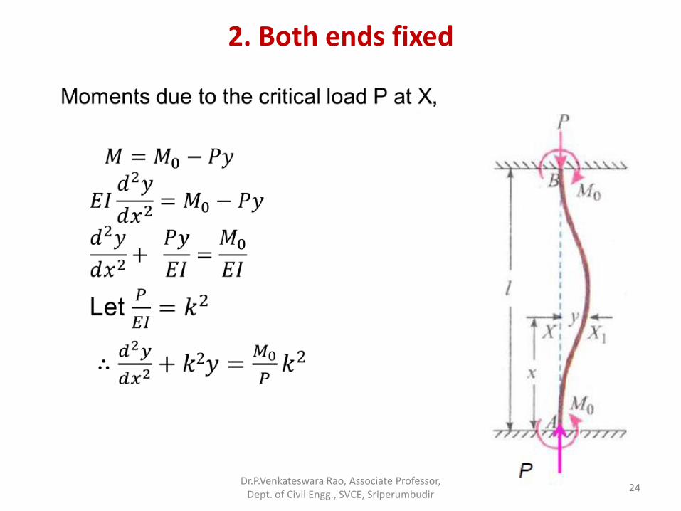
2. Both ends fixed
Dr.P.Venkateswara Rao, Associate Professor, Dept. of Civil Engg., SVCE, Sriperumbudir
24
2. Both ends fixed (contd…)
Dr.P.Venkateswara Rao, Associate Professor, Dept. of Civil Engg., SVCE, Sriperumbudir
25
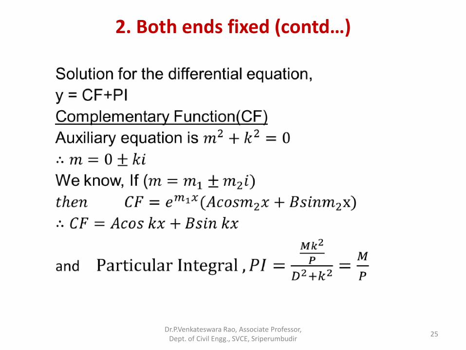
2. Both ends fixed (contd…)
Dr.P.Venkateswara Rao, Associate Professor, Dept. of Civil Engg., SVCE, Sriperumbudir
26
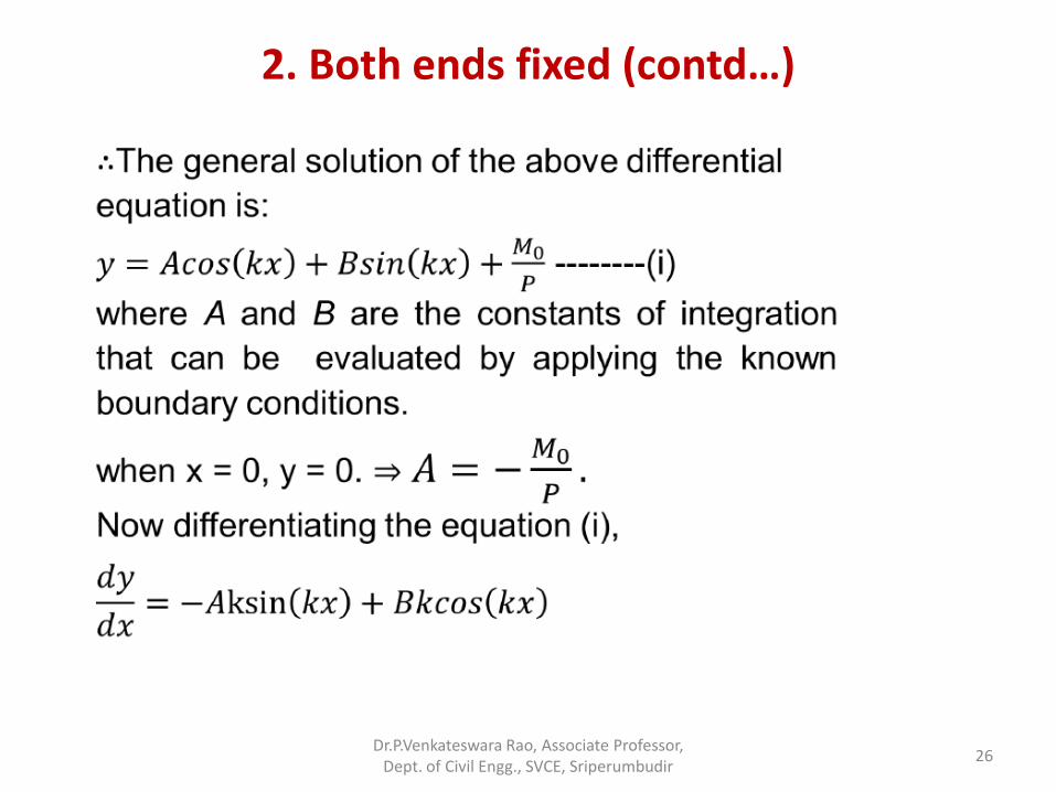
2. Both ends fixed (contd…)
Dr.P.Venkateswara Rao, Associate Professor, Dept. of Civil Engg., SVCE, Sriperumbudir
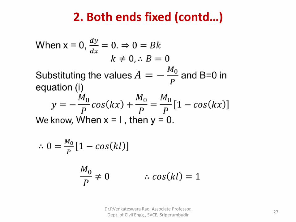
27
2. Both ends fixed (contd…)
Dr.P.Venkateswara Rao, Associate Professor, Dept. of Civil Engg., SVCE, Sriperumbudir
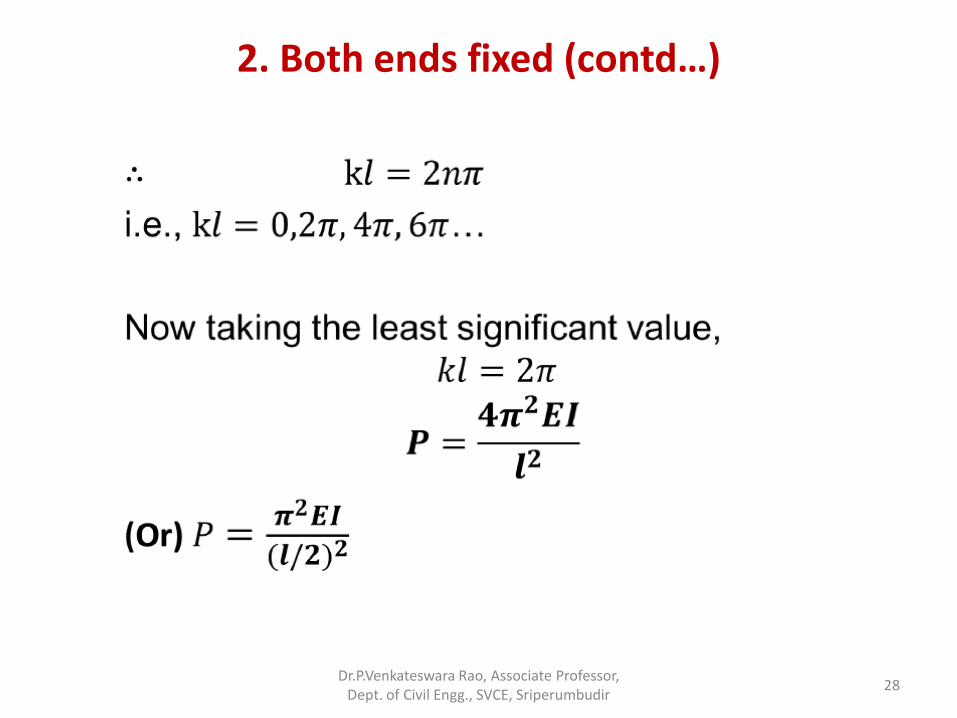
28
3. One end fixed and other hinged
Dr.P.Venkateswara Rao, Associate Professor, Dept. of Civil Engg., SVCE, Sriperumbudir
29
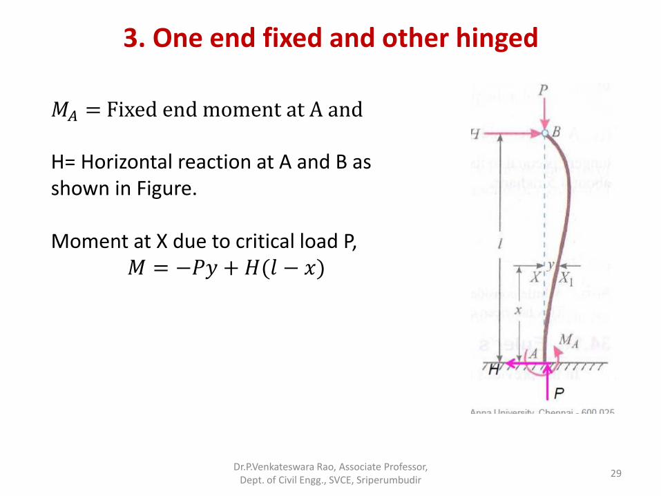
𝑀𝐴 = Fixed end moment at A and
H= Horizontal reaction at A and B as shown in Figure. Moment at X due to critical load P,
𝑀 = −𝑃𝑦 + 𝐻(𝑙 − 𝑥)
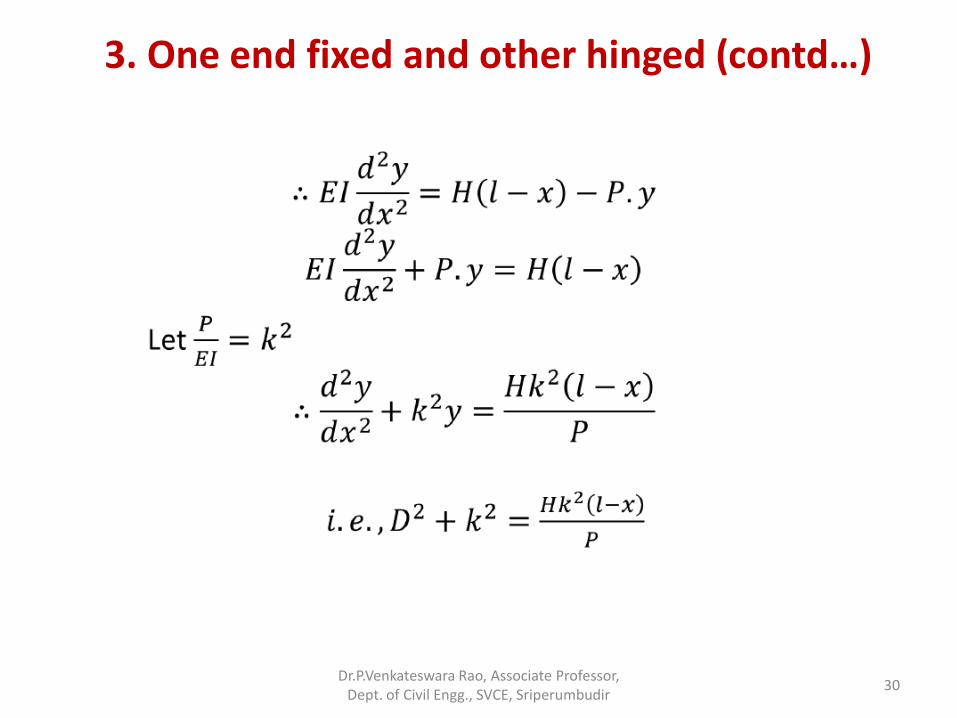
3. One end fixed and other hinged (contd…)
Dr.P.Venkateswara Rao, Associate Professor, Dept. of Civil Engg., SVCE, Sriperumbudir
30
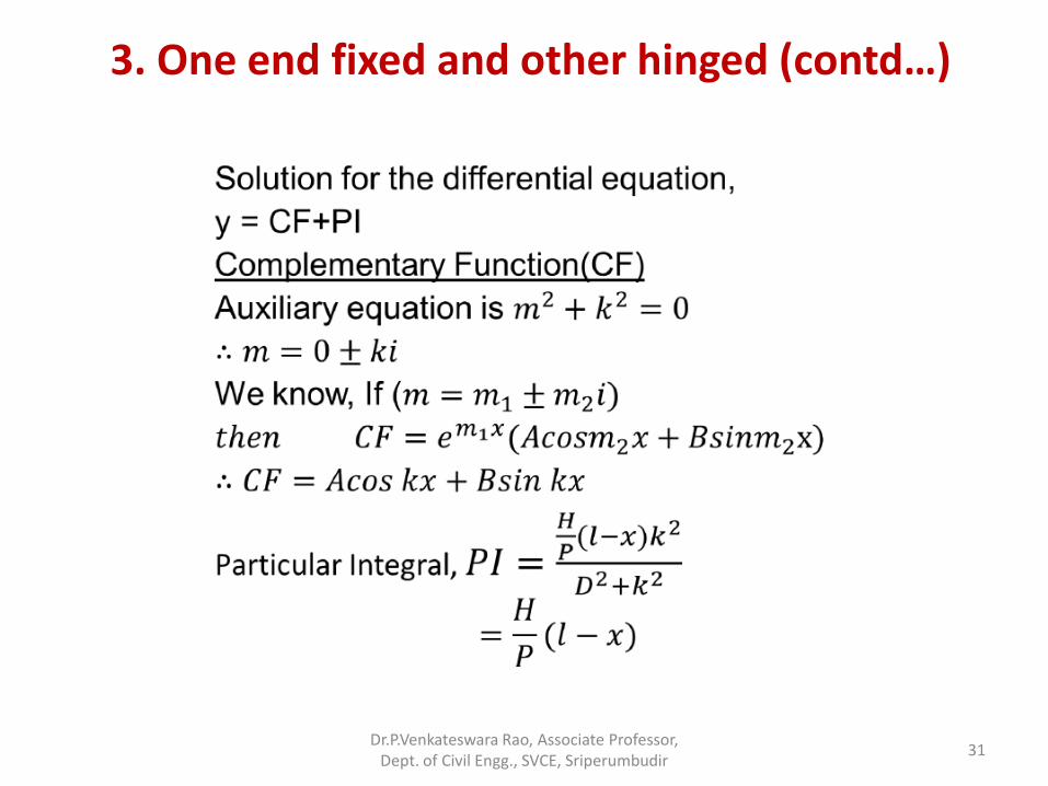
3. One end fixed and other hinged (contd…)
Dr.P.Venkateswara Rao, Associate Professor, Dept. of Civil Engg., SVCE, Sriperumbudir
31
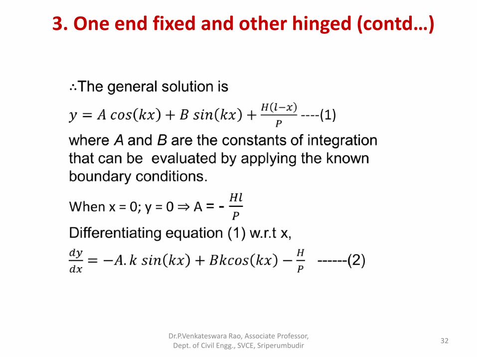
3. One end fixed and other hinged (contd…)
Dr.P.Venkateswara Rao, Associate Professor, Dept. of Civil Engg., SVCE, Sriperumbudir
32
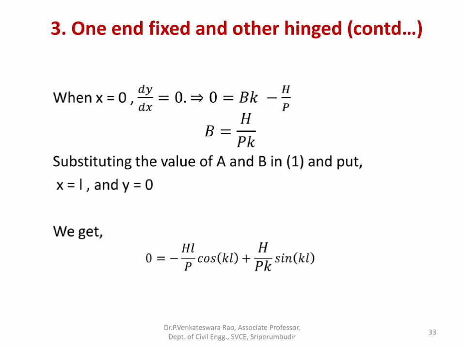
3. One end fixed and other hinged (contd…)
Dr.P.Venkateswara Rao, Associate Professor, Dept. of Civil Engg., SVCE, Sriperumbudir
33
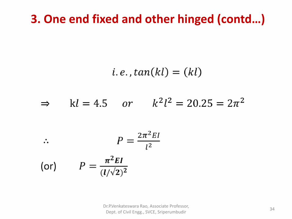
3. One end fixed and other hinged (contd…)
Dr.P.Venkateswara Rao, Associate Professor, Dept. of Civil Engg., SVCE, Sriperumbudir
34
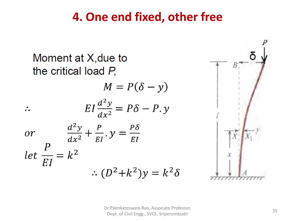
4. One end fixed, other free
Dr.P.Venkateswara Rao, Associate Professor, Dept. of Civil Engg., SVCE, Sriperumbudir
35
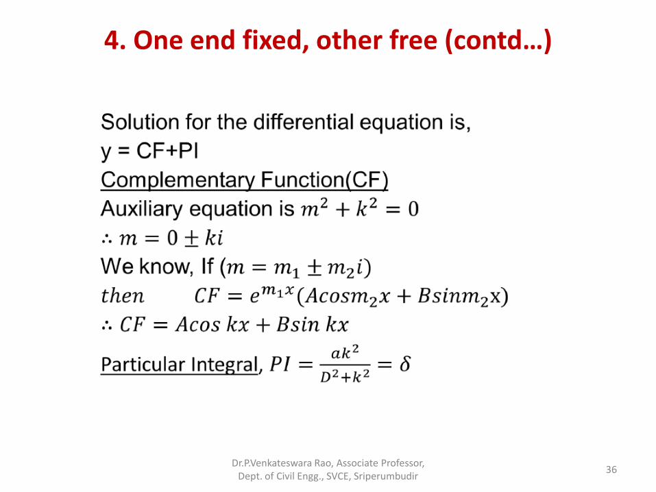
4. One end fixed, other free (contd…)
Dr.P.Venkateswara Rao, Associate Professor, Dept. of Civil Engg., SVCE, Sriperumbudir
36
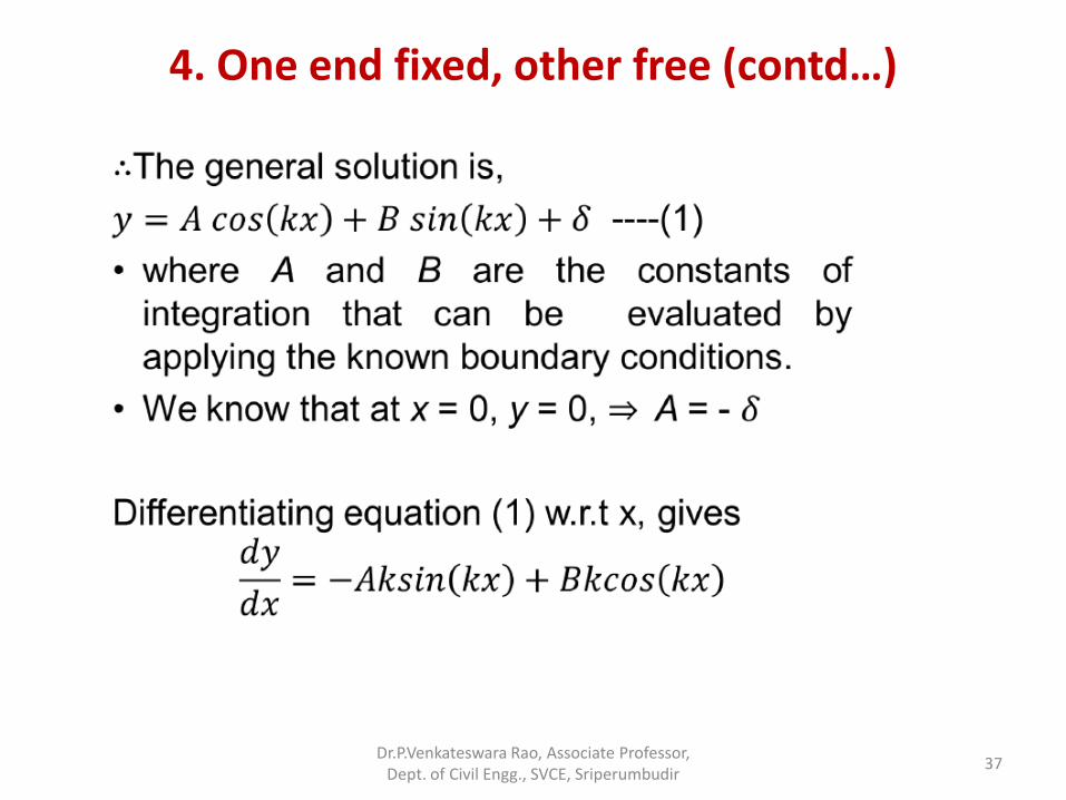
4. One end fixed, other free (contd…)
Dr.P.Venkateswara Rao, Associate Professor, Dept. of Civil Engg., SVCE, Sriperumbudir
37
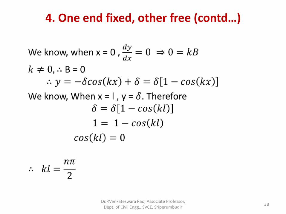
4. One end fixed, other free (contd…)
Dr.P.Venkateswara Rao, Associate Professor, Dept. of Civil Engg., SVCE, Sriperumbudir
38
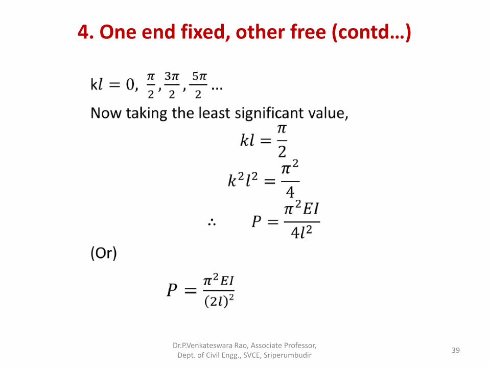
4. One end fixed, other free (contd…)
Dr.P.Venkateswara Rao, Associate Professor, Dept. of Civil Engg., SVCE, Sriperumbudir
39
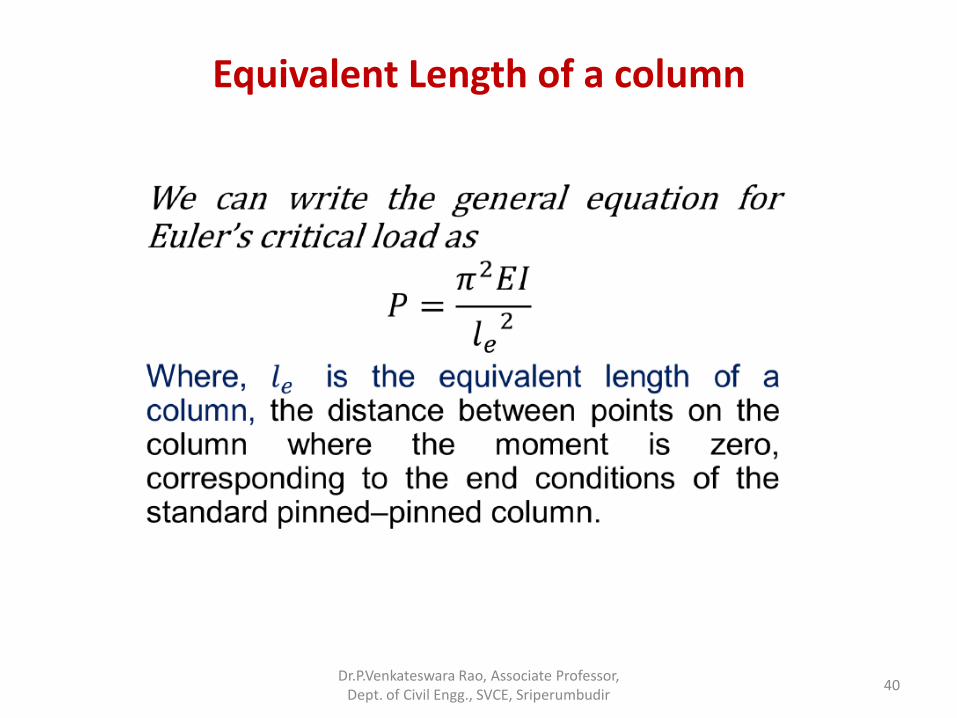
Equivalent Length of a column
Dr.P.Venkateswara Rao, Associate Professor, Dept. of Civil Engg., SVCE, Sriperumbudir
40
Equivalent length (Effective Length)
Dr.P.Venkateswara Rao, Associate Professor, Dept. of Civil Engg., SVCE, Sriperumbudir
41
Effective Length
• Physically, the effective length is the distance between points on the buckled column where the moment goes to zero, i.e., where the column is effectively pinned. Considering the deflected shape, the moment is zero where the curvature is zero (from beam theory).
• Zero curvature corresponds to an inflection point in the deflected shape (where the curvature changes sign).
Dr.P.Venkateswara Rao, Associate Professor, Dept. of Civil Engg., SVCE, Sriperumbudir
42
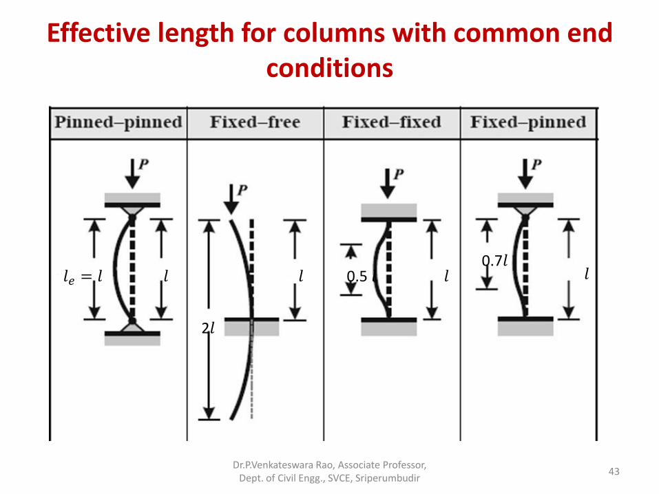
Effective length for columns with common end conditions
𝑙𝑒 = 𝑙 𝑙
2𝑙
𝑙 0.5 𝑙 𝑙 0.7𝑙
𝑙
Dr.P.Venkateswara Rao, Associate Professor, Dept. of Civil Engg., SVCE, Sriperumbudir
43
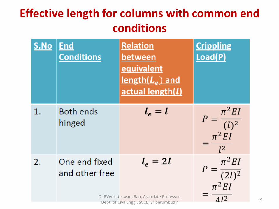
Effective length for columns with common end conditions
Dr.P.Venkateswara Rao, Associate Professor, Dept. of Civil Engg., SVCE, Sriperumbudir
44
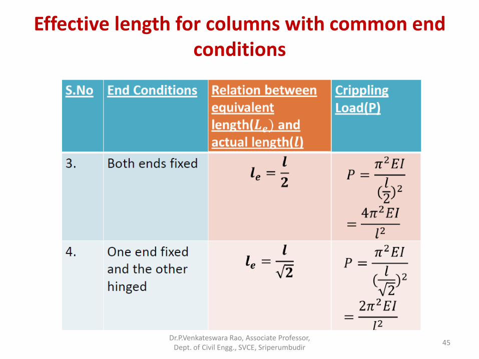
Effective length for columns with common end conditions
Dr.P.Venkateswara Rao, Associate Professor, Dept. of Civil Engg., SVCE, Sriperumbudir
45
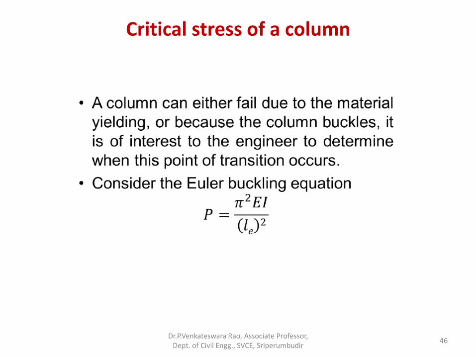
Critical stress of a column
Dr.P.Venkateswara Rao, Associate Professor, Dept. of Civil Engg., SVCE, Sriperumbudir
46
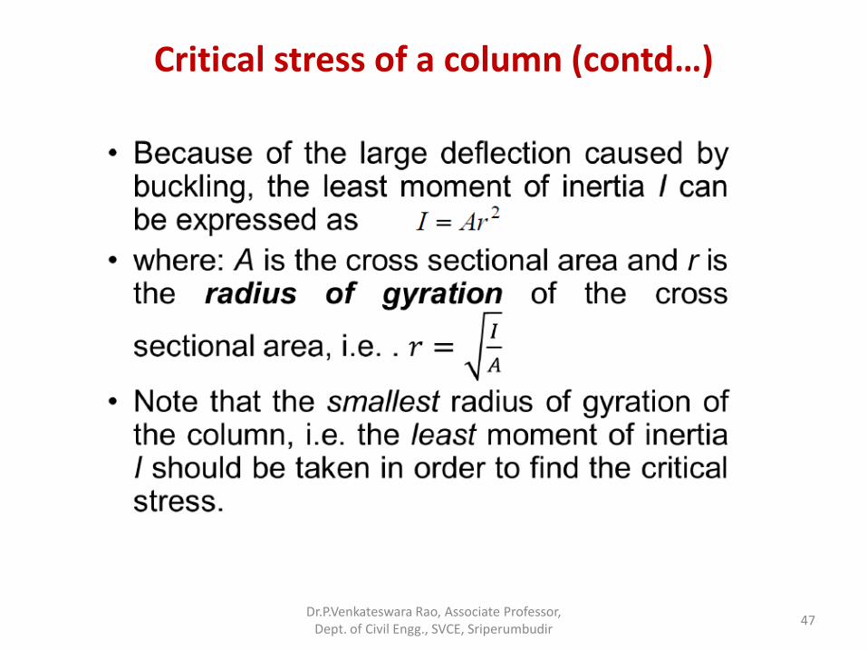
Critical stress of a column (contd…)
Dr.P.Venkateswara Rao, Associate Professor, Dept. of Civil Engg., SVCE, Sriperumbudir
47
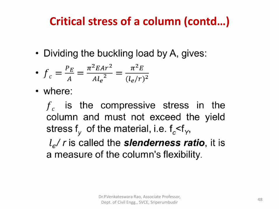
Critical stress of a column (contd…)
Dr.P.Venkateswara Rao, Associate Professor, Dept. of Civil Engg., SVCE, Sriperumbudir
48
Limitations of Euler’s formula
• 1. It is applicable to an ideal strut only and in practice, there is always crookedness in the column and the load applied may not be exactly co-axial.
• 2. It takes no account of direct stress. It means that it may give a buckling load for struts, far in excess of load which they can be withstand under direct compression.
Dr.P.Venkateswara Rao, Associate Professor, Dept. of Civil Engg., SVCE, Sriperumbudir
49
Problems
Problem. A hollow circular column of internal diameter 20 mm and external diameter 40 mm has a total length of 5m. One end of the column is fixed and the other end is hinged. Find out the crippling stress of the column if 𝐸 = 2 × 10⁵ N/mm2. Also findout the shortest length of this column for which Euler’s formula is valid taking the yield stress equal to 250 N/mm2 .
Dr.P.Venkateswara Rao, Associate Professor, Dept. of Civil Engg., SVCE, Sriperumbudir
50
Problems
Solution.
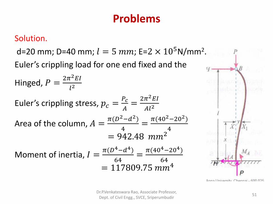
d=20 mm; D=40 mm; 𝑙 = 5 𝑚𝑚; E=2 × 10⁵N/mm2.
Euler’s crippling load for one end fixed and the
Hinged, 𝑃 =2𝜋2𝐸𝐼
𝑙2
Euler’s crippling stress, 𝑝𝑐 =𝑃𝑐
𝐴=
2𝜋2𝐸𝐼
𝐴𝑙2
Area of the column, 𝐴 =𝜋(𝐷2−𝑑2)
4=
𝜋(402−202)
4
= 942.48 𝑚𝑚2
Moment of inertia, 𝐼 =𝜋(𝐷4−𝑑4)
64=
𝜋(404−204)
64
= 117809.75 𝑚𝑚4
Dr.P.Venkateswara Rao, Associate Professor, Dept. of Civil Engg., SVCE, Sriperumbudir
51
Problems
Solution.
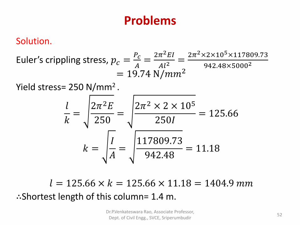
Euler’s crippling stress, 𝑝𝑐 =𝑃𝑐
𝐴=
2𝜋2𝐸𝐼
𝐴𝑙2=
2𝜋2×2×105×117809.73
942.48×50002
= 19.74 N/𝑚𝑚2
Yield stress= 250 N/mm2 .
𝑙
𝑘=
2𝜋2𝐸
250=
2𝜋2 × 2 × 105
250𝐼= 125.66
𝑘 =𝐼
𝐴=
117809.73
942.48= 11.18
𝑙 = 125.66 × 𝑘 = 125.66 × 11.18 = 1404.9 𝑚𝑚
∴Shortest length of this column= 1.4 m.
Dr.P.Venkateswara Rao, Associate Professor, Dept. of Civil Engg., SVCE, Sriperumbudir
52
Problems
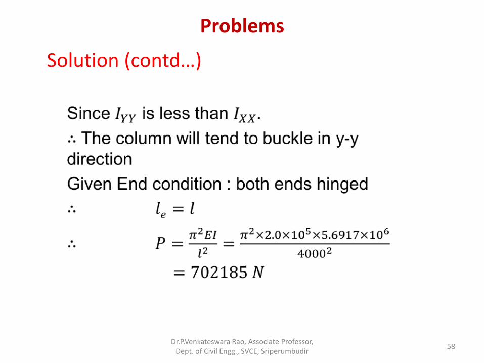
Problem1. A T-section 150 mm x 120 mm x 20 mm is used as a strut of 4 m long with hinged at its both ends. Calculate the crippling load if modulus of elasticity for the material be 2.0 x 10⁵
N/mm2.
Dr.P.Venkateswara Rao, Associate Professor, Dept. of Civil Engg., SVCE, Sriperumbudir
53
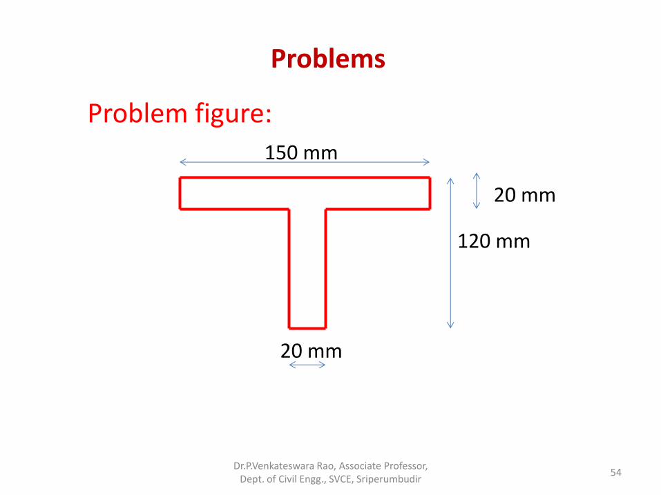
150 mm
120 mm
20 mm
20 mm
Problems
Problem figure:
Dr.P.Venkateswara Rao, Associate Professor, Dept. of Civil Engg., SVCE, Sriperumbudir
54
Problems
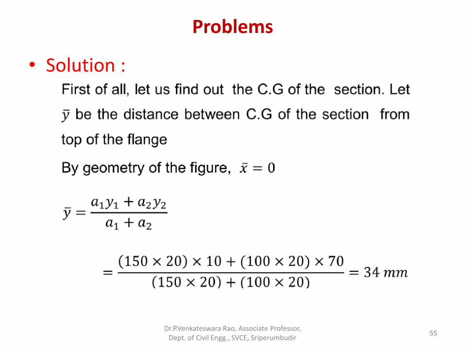
• Solution :
Dr.P.Venkateswara Rao, Associate Professor, Dept. of Civil Engg., SVCE, Sriperumbudir
55
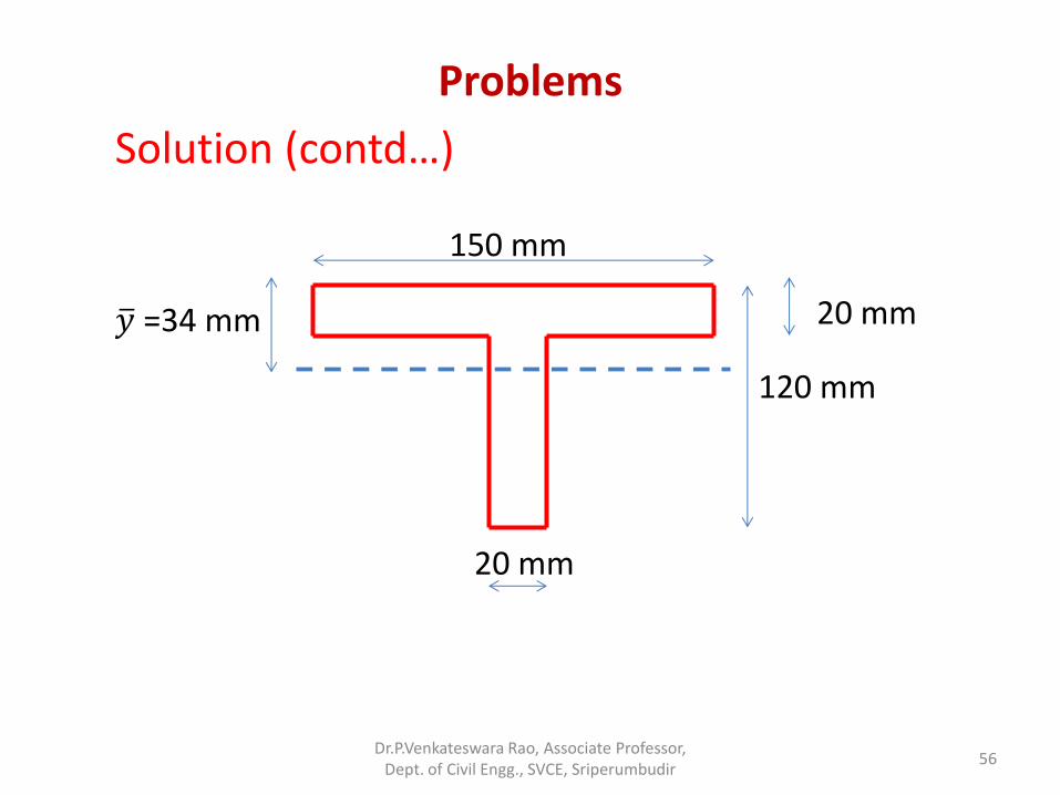
150 mm
120 mm
20 mm
20 mm
𝑦 =34 mm
Problems
Solution (contd…)
Dr.P.Venkateswara Rao, Associate Professor, Dept. of Civil Engg., SVCE, Sriperumbudir
56
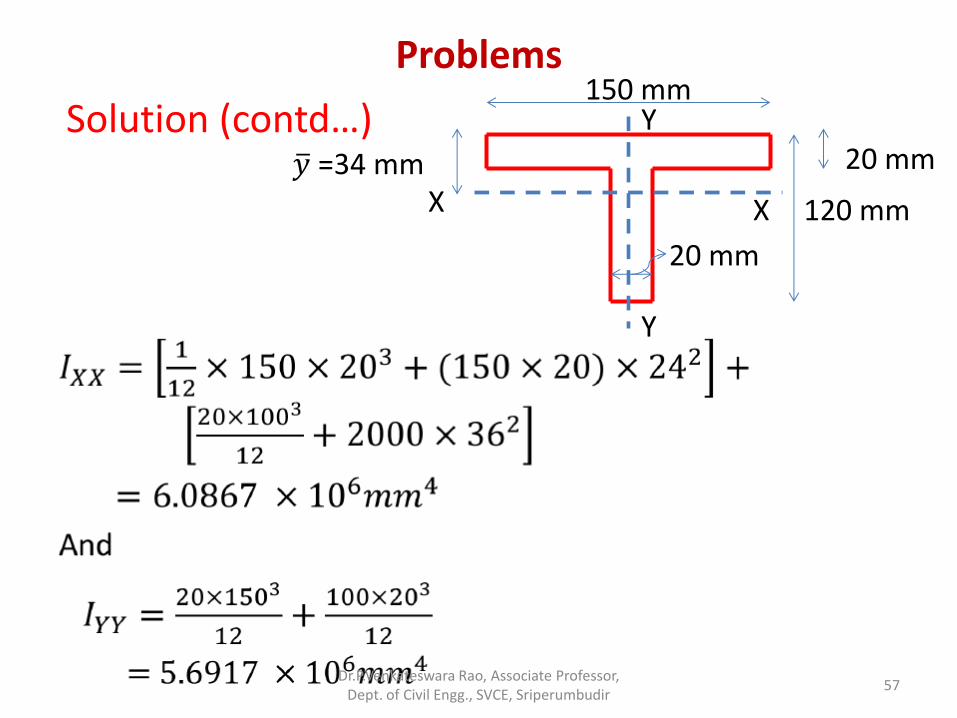
Problems 150 mm
120 mm
20 mm
20 mm
𝑦 =34 mm X X
Y
Y
Solution (contd…)
Dr.P.Venkateswara Rao, Associate Professor, Dept. of Civil Engg., SVCE, Sriperumbudir
57
Problems
Solution (contd…)
Dr.P.Venkateswara Rao, Associate Professor, Dept. of Civil Engg., SVCE, Sriperumbudir
58
Problems
• Problem 2: Compare the ratio of the strength of a solid steel column to that of a hollow of the same cross-sectional area. The internal diameter of the hollow column is ¾ of the external diameter. Both the column have the same length and are pinned at both ends.
Dr.P.Venkateswara Rao, Associate Professor, Dept. of Civil Engg., SVCE, Sriperumbudir
59
Problems
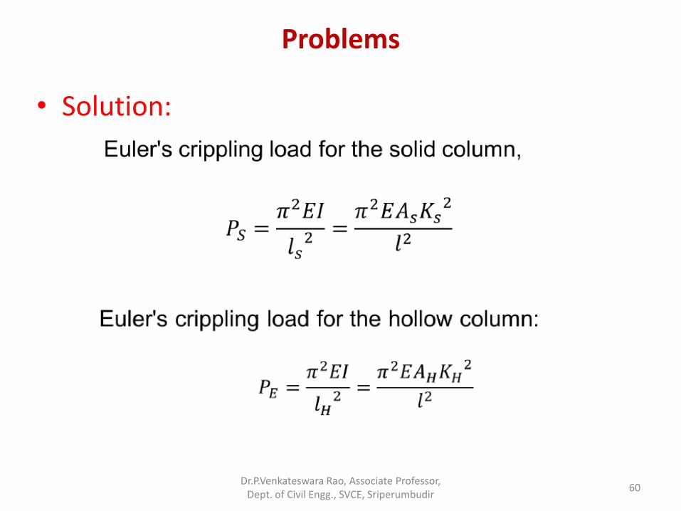
• Solution:
Dr.P.Venkateswara Rao, Associate Professor, Dept. of Civil Engg., SVCE, Sriperumbudir
60
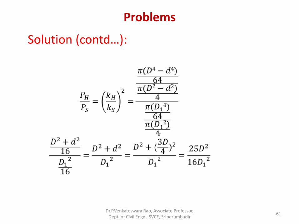
Problems
Solution (contd…):
Dr.P.Venkateswara Rao, Associate Professor, Dept. of Civil Engg., SVCE, Sriperumbudir
61
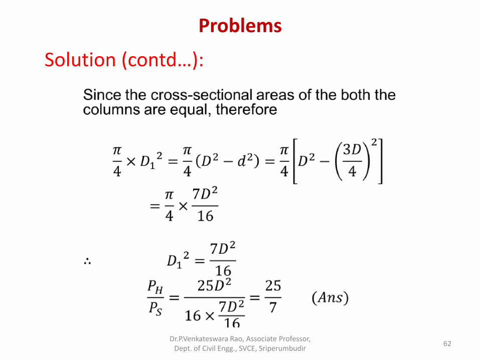
Problems
Solution (contd…):
Dr.P.Venkateswara Rao, Associate Professor, Dept. of Civil Engg., SVCE, Sriperumbudir
62
Intermediate columns: Empirical Formulae
• Euler’s formula is valid only for long columns, i.e. for columns
having 𝐿
𝐾 ratio greater than a certain value for a particular
material.
• Euler’s formula though valid for 𝐿
𝑘> 89 for mild steel column,
doesn’t take into account the direct compressive stress.
• For intermediate columns, empirical formulae i.e., Rankine’s formula, Gordan’s formula and Johnson’s formulae are appropriate.
Dr.P.Venkateswara Rao, Associate Professor, Dept. of Civil Engg., SVCE, Sriperumbudir
63
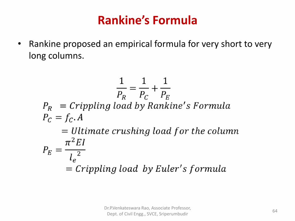
Rankine’s Formula
• Rankine proposed an empirical formula for very short to very long columns.
Dr.P.Venkateswara Rao, Associate Professor, Dept. of Civil Engg., SVCE, Sriperumbudir
64
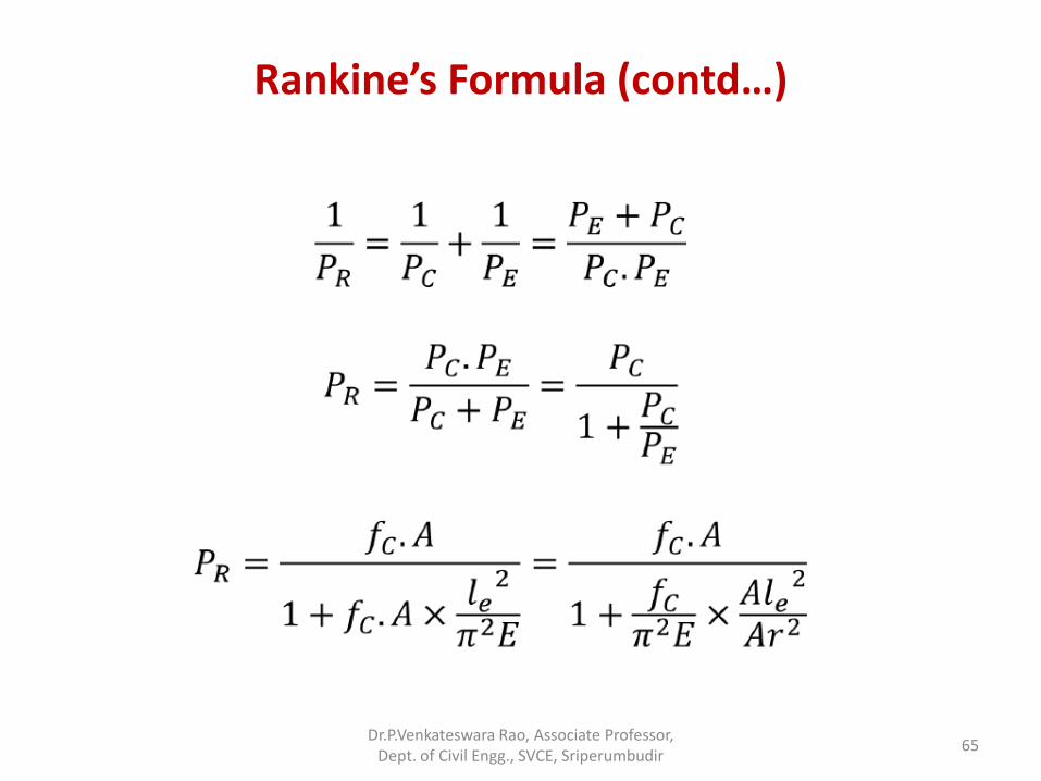
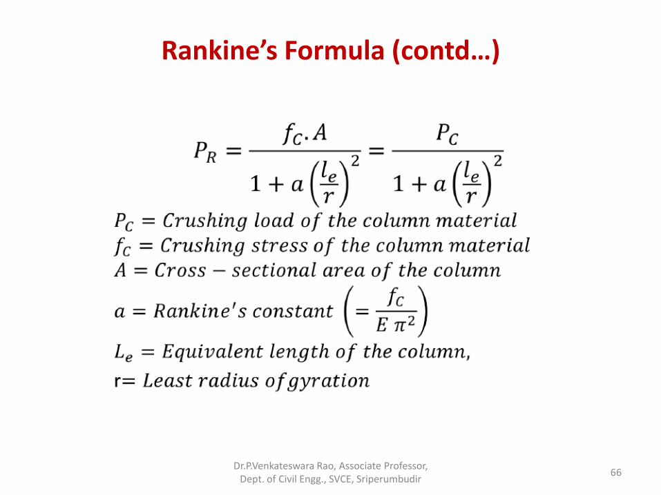
Rankine’s Formula (contd…)
Dr.P.Venkateswara Rao, Associate Professor, Dept. of Civil Engg., SVCE, Sriperumbudir
65
Rankine’s Formula (contd…)
Dr.P.Venkateswara Rao, Associate Professor, Dept. of Civil Engg., SVCE, Sriperumbudir
66
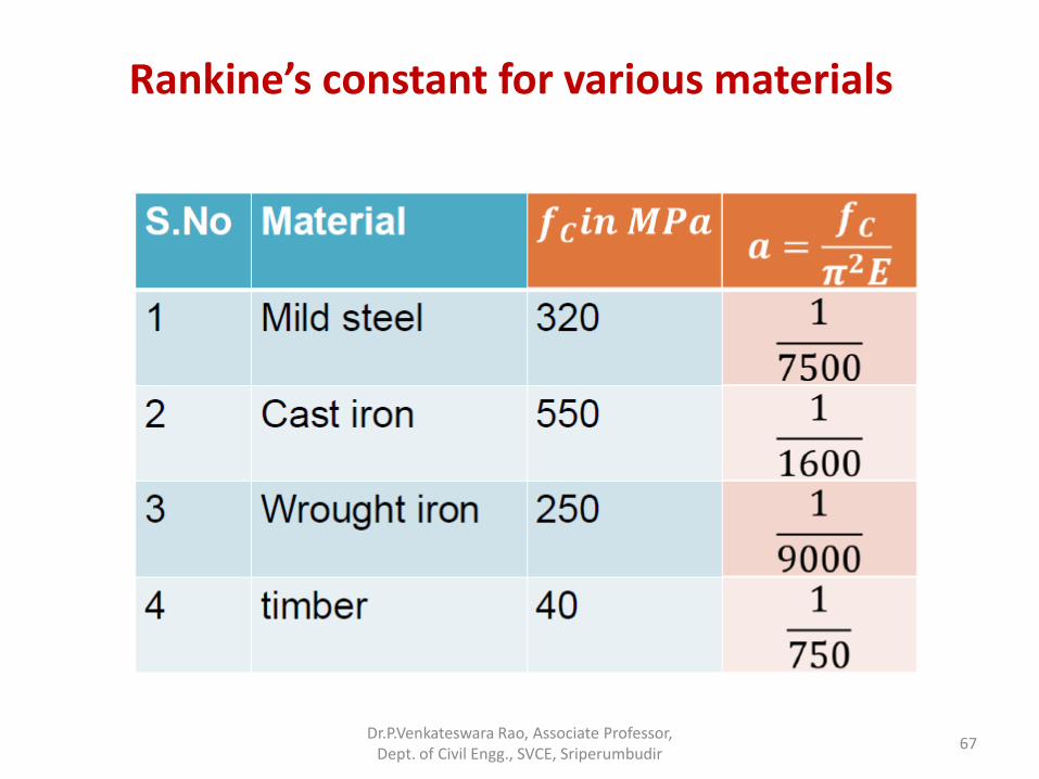
Rankine’s constant for various materials
Dr.P.Venkateswara Rao, Associate Professor, Dept. of Civil Engg., SVCE, Sriperumbudir
67
Problems
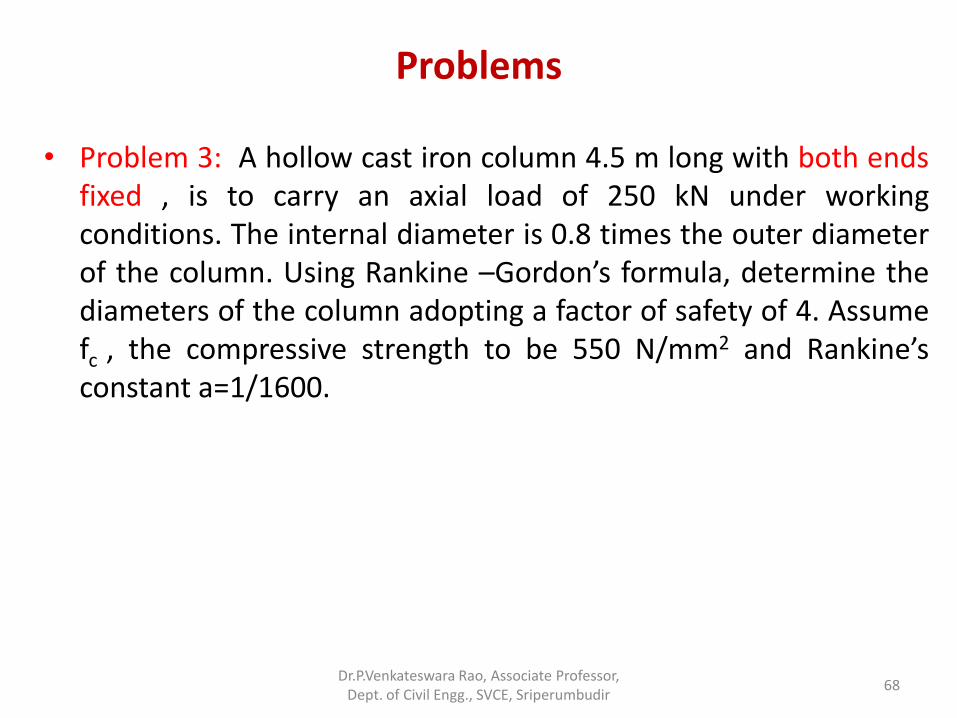
• Problem 3: A hollow cast iron column 4.5 m long with both ends fixed , is to carry an axial load of 250 kN under working conditions. The internal diameter is 0.8 times the outer diameter of the column. Using Rankine –Gordon’s formula, determine the diameters of the column adopting a factor of safety of 4. Assume fc , the compressive strength to be 550 N/mm2 and Rankine’s constant a=1/1600.
Dr.P.Venkateswara Rao, Associate Professor, Dept. of Civil Engg., SVCE, Sriperumbudir
68
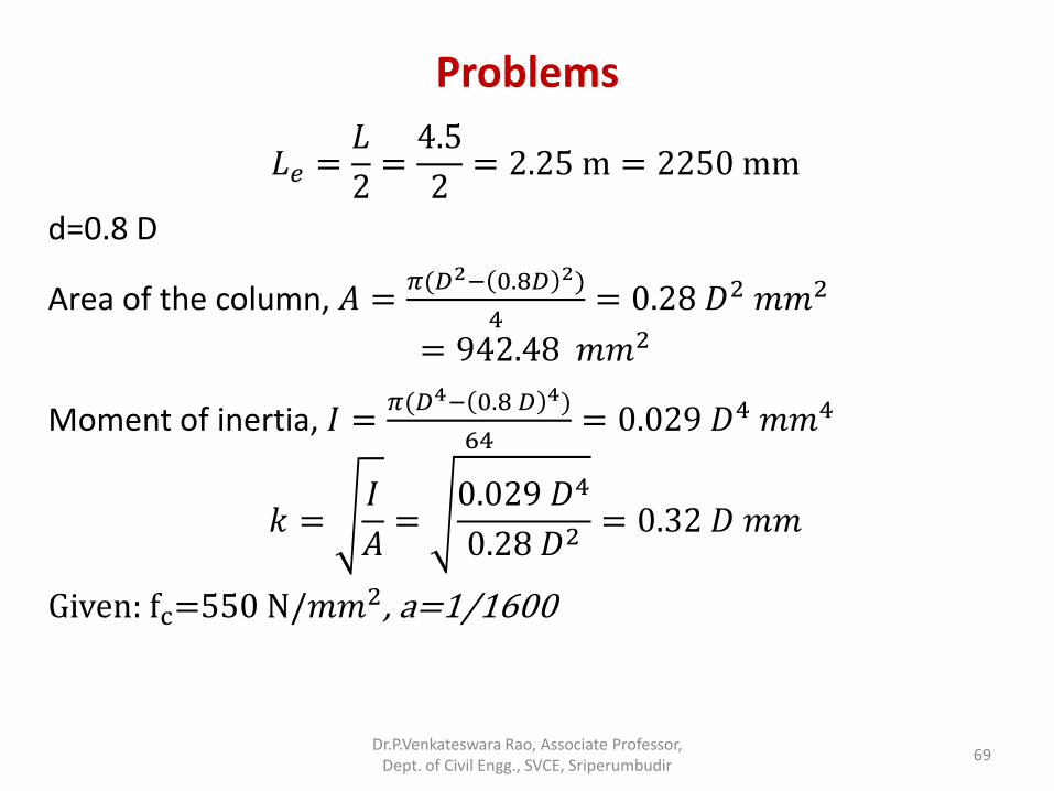
Problems
𝐿𝑒 =𝐿
2=4.5
2= 2.25 m = 2250 mm
d=0.8 D
Area of the column, 𝐴 =𝜋(𝐷2− 0.8𝐷 2)
4= 0.28 𝐷2 𝑚𝑚2
= 942.48 𝑚𝑚2
Moment of inertia, 𝐼 =𝜋(𝐷4− 0.8 𝐷 4)
64= 0.029 𝐷4 𝑚𝑚4
𝑘 =𝐼
𝐴=
0.029 𝐷4
0.28 𝐷2= 0.32 𝐷 𝑚𝑚
Given: fc=550 N/𝑚𝑚2, a=1/1600
Dr.P.Venkateswara Rao, Associate Professor, Dept. of Civil Engg., SVCE, Sriperumbudir
69
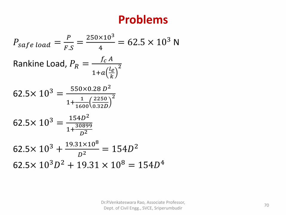
Problems
𝑃𝑠𝑎𝑓𝑒 𝑙𝑜𝑎𝑑 =𝑃
𝐹.𝑆=
250×103
4= 62.5 × 10³ N
Rankine Load, 𝑃𝑅 =𝑓𝑐 𝐴
1+𝑎𝑙𝑒𝑘
2
62.5× 103 =550×0.28 𝐷2
1+1
1600
2250
0.32𝐷
2
62.5× 103 =154𝐷2
1+30899
𝐷2
62.5× 10³ +19.31×10⁸
𝐷2 = 154𝐷2
62.5× 10³𝐷2 + 19.31 × 108 = 154𝐷4
Dr.P.Venkateswara Rao, Associate Professor, Dept. of Civil Engg., SVCE, Sriperumbudir
70
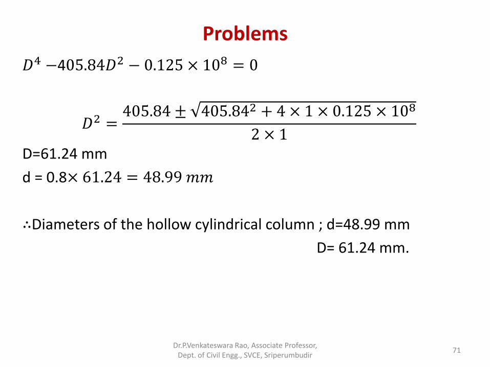
Problems
𝐷4 −405.84𝐷2 − 0.125 × 108 = 0
𝐷2 =405.84 ± 405.842 + 4 × 1 × 0.125 × 108
2 × 1
D=61.24 mm
d = 0.8× 61.24 = 48.99 𝑚𝑚
∴Diameters of the hollow cylindrical column ; d=48.99 mm
D= 61.24 mm.
Dr.P.Venkateswara Rao, Associate Professor, Dept. of Civil Engg., SVCE, Sriperumbudir
71
Problems
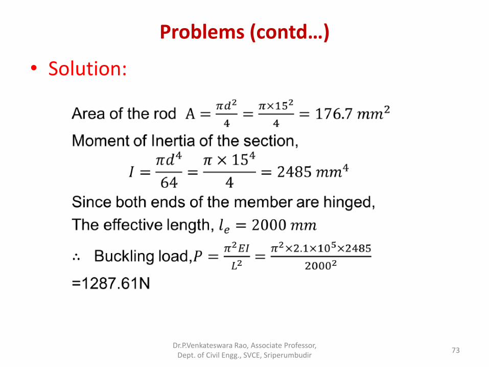
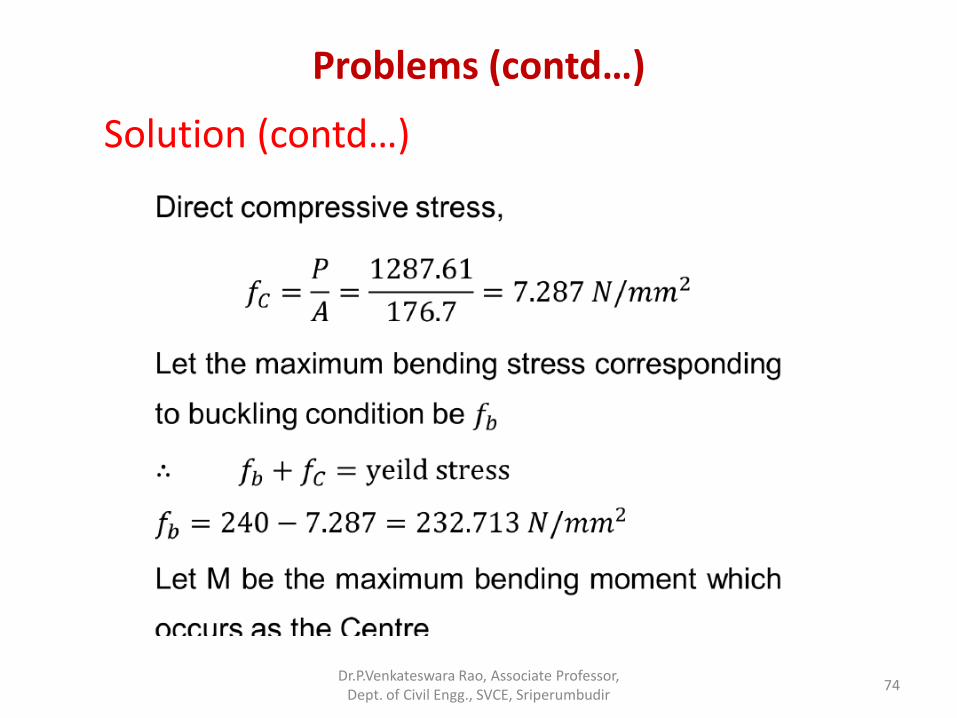
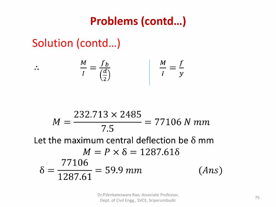
• Problem 4: A round steel rod of diameter 15 mm and length 2m is subjected to a gradual increasing axial compressive load. Using Euler’s formula find the buckling load. Find also the maximum lateral deflection corresponding to the buckling condition. Both ends of the rod may be taken as hinged. Take E = 2.1 x 10⁵ N/mm2 and the yield stress of steel = 240 N/mm2.
Dr.P.Venkateswara Rao, Associate Professor, Dept. of Civil Engg., SVCE, Sriperumbudir
72
Problems (contd…)
• Solution:
Dr.P.Venkateswara Rao, Associate Professor, Dept. of Civil Engg., SVCE, Sriperumbudir
73
Problems (contd…)
Solution (contd…)
Dr.P.Venkateswara Rao, Associate Professor, Dept. of Civil Engg., SVCE, Sriperumbudir
74
Problems (contd…)
Solution (contd…)
Dr.P.Venkateswara Rao, Associate Professor, Dept. of Civil Engg., SVCE, Sriperumbudir
75
Problems (contd…)
• Problem 5: A cast iron hollow cylindrical column 3 m in length when hinged at both ends, has a critical buckling load of P kN. When this column is fixed at both the ends, its critical load rises to P+300 kN. If the ratio of external diameter to internal diameter is 1.25 and E = 1.0x10⁵ N/mm2. Determine the external diameter of the column.
Dr.P.Venkateswara Rao, Associate Professor, Dept. of Civil Engg., SVCE, Sriperumbudir
76
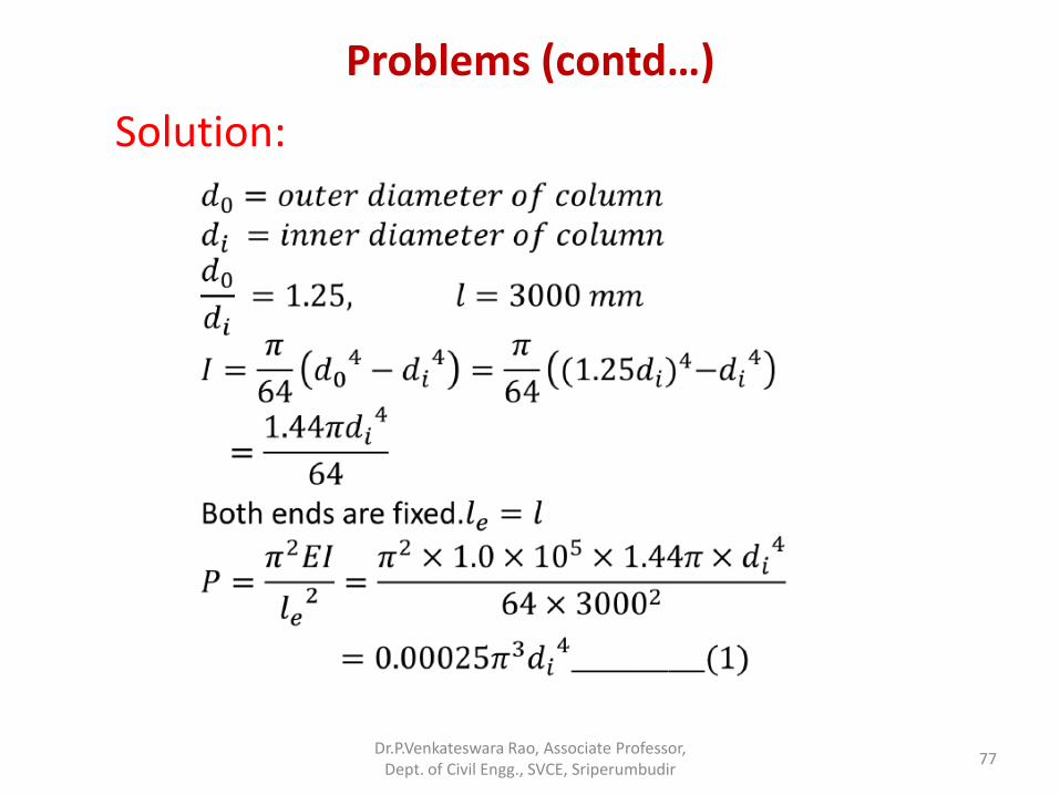
Problems (contd…)
Solution:
Dr.P.Venkateswara Rao, Associate Professor, Dept. of Civil Engg., SVCE, Sriperumbudir
77
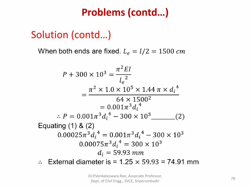
Problems (contd…)
Solution (contd…)
Dr.P.Venkateswara Rao, Associate Professor, Dept. of Civil Engg., SVCE, Sriperumbudir
78
Problems (contd…)
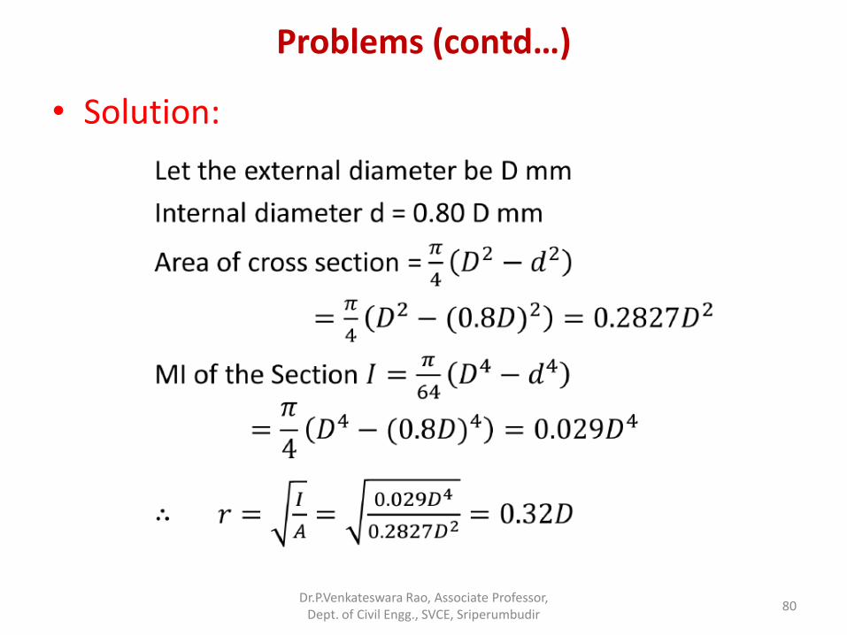
• Problem 5: A hollow cylindrical cast iron column is 4 m long, both ends being fixed. Design the column to carry an axial load of 250 kN. Use Rankine’s formula and adopt a factor of safety of 5. The internal diameter may be taken as 0.8 times the
external diameter. Take 𝑓𝑐 = 550 N/mm2 and 𝑎 =1
1600.
Dr.P.Venkateswara Rao, Associate Professor, Dept. of Civil Engg., SVCE, Sriperumbudir
79
Problems (contd…)
• Solution:
Dr.P.Venkateswara Rao, Associate Professor, Dept. of Civil Engg., SVCE, Sriperumbudir
80
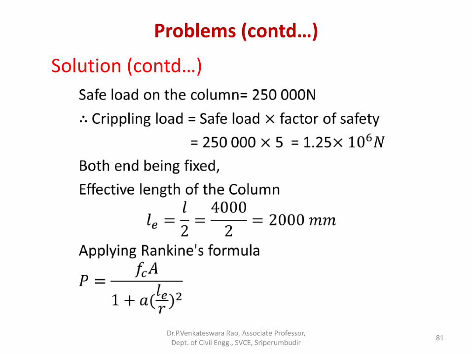
Problems (contd…)
Solution (contd…)
Dr.P.Venkateswara Rao, Associate Professor, Dept. of Civil Engg., SVCE, Sriperumbudir
81
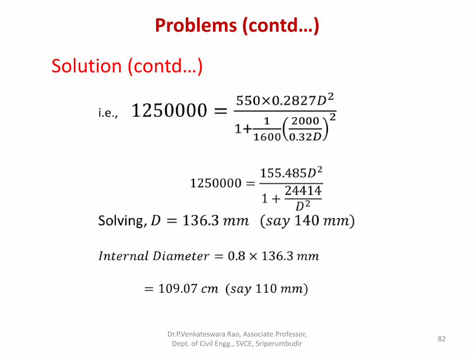
Problems (contd…)
Solution (contd…)
Dr.P.Venkateswara Rao, Associate Professor, Dept. of Civil Engg., SVCE, Sriperumbudir
82
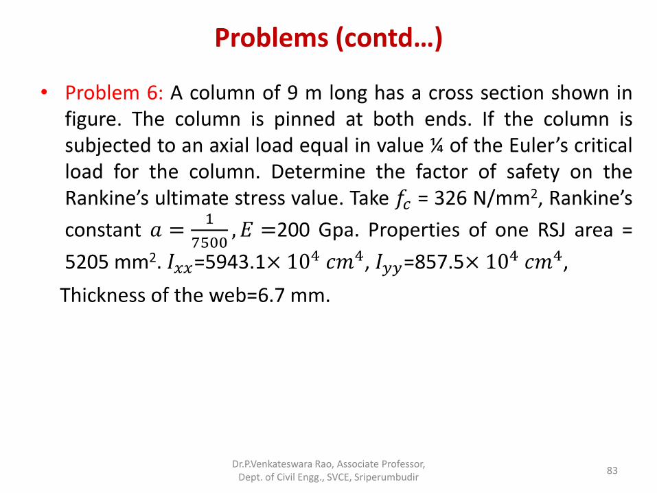
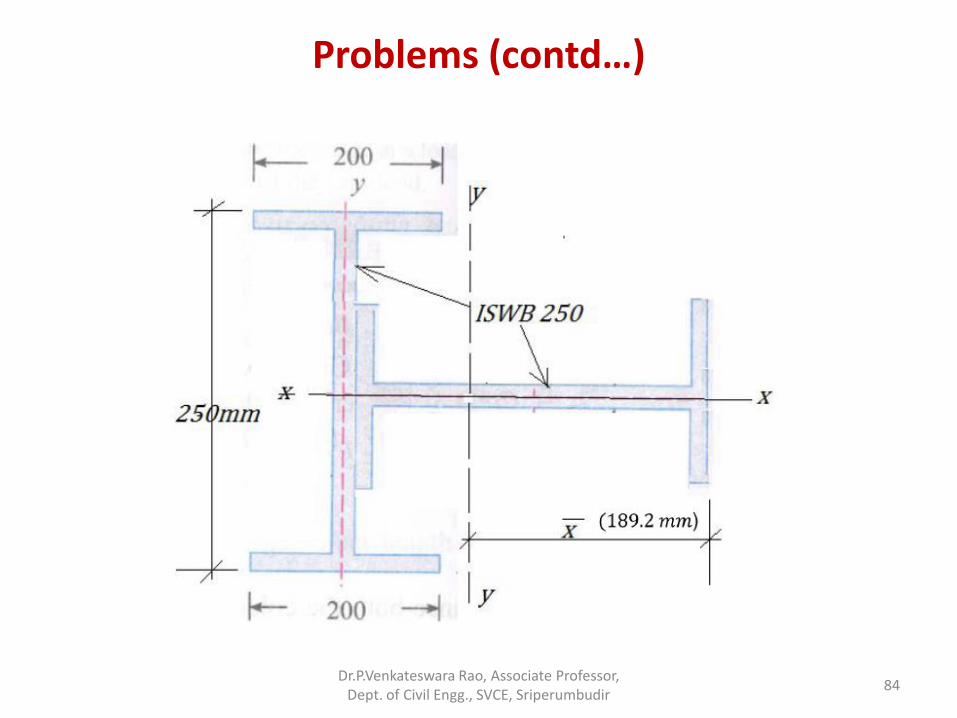
Problems (contd…)
• Problem 6: A column of 9 m long has a cross section shown in figure. The column is pinned at both ends. If the column is subjected to an axial load equal in value ¼ of the Euler’s critical load for the column. Determine the factor of safety on the Rankine’s ultimate stress value. Take 𝑓𝑐 = 326 N/mm2, Rankine’s
constant 𝑎 =1
7500, 𝐸 =200 Gpa. Properties of one RSJ area =
5205 mm2. 𝐼𝑥𝑥=5943.1× 104 𝑐𝑚4, 𝐼𝑦𝑦=857.5× 10⁴ 𝑐𝑚4,
Thickness of the web=6.7 mm.
Dr.P.Venkateswara Rao, Associate Professor, Dept. of Civil Engg., SVCE, Sriperumbudir
83
Problems (contd…)
Dr.P.Venkateswara Rao, Associate Professor, Dept. of Civil Engg., SVCE, Sriperumbudir
84
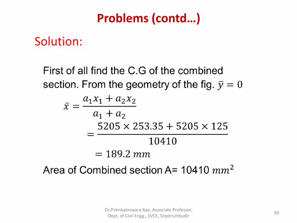
Problems (contd…)
Solution:
Dr.P.Venkateswara Rao, Associate Professor, Dept. of Civil Engg., SVCE, Sriperumbudir
85
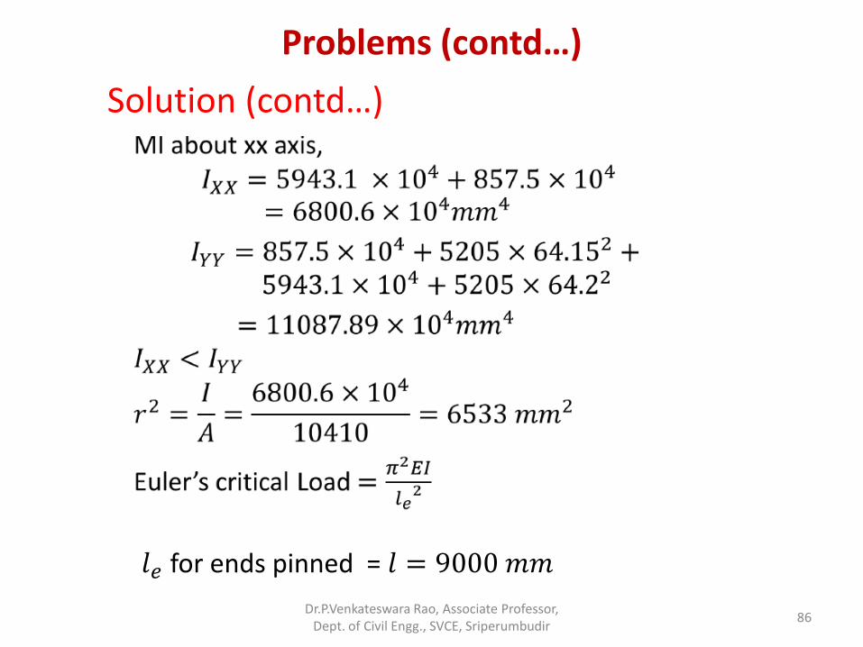
Problems (contd…)
Solution (contd…)
𝑙𝑒 for ends pinned = 𝑙 = 9000 𝑚𝑚
Dr.P.Venkateswara Rao, Associate Professor, Dept. of Civil Engg., SVCE, Sriperumbudir
86
Problems (contd…)
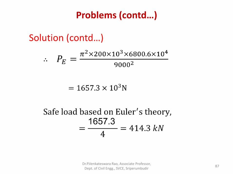
Solution (contd…)
Dr.P.Venkateswara Rao, Associate Professor, Dept. of Civil Engg., SVCE, Sriperumbudir
87
Problems (contd…)
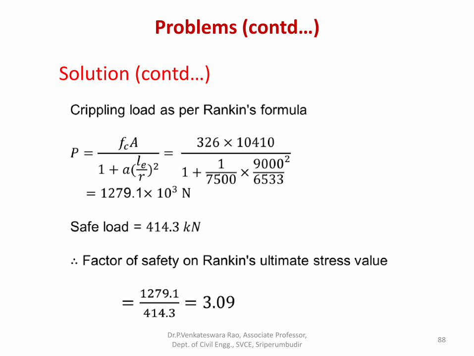
Solution (contd…)
Dr.P.Venkateswara Rao, Associate Professor, Dept. of Civil Engg., SVCE, Sriperumbudir
88
Problems (contd…)
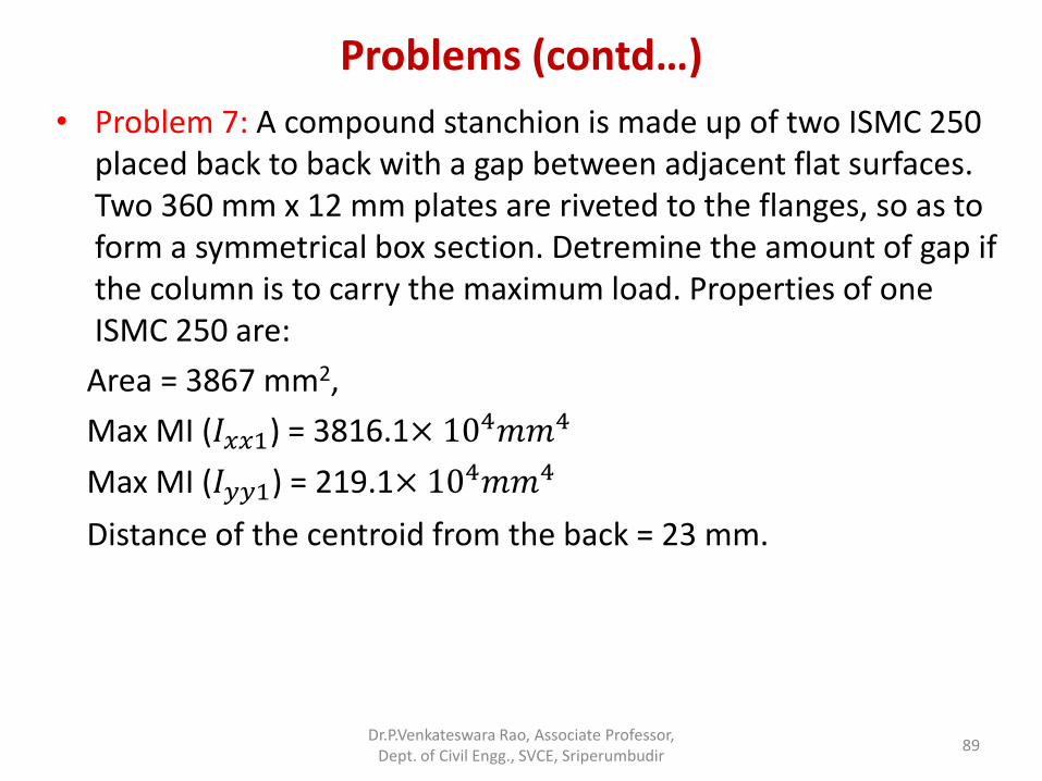
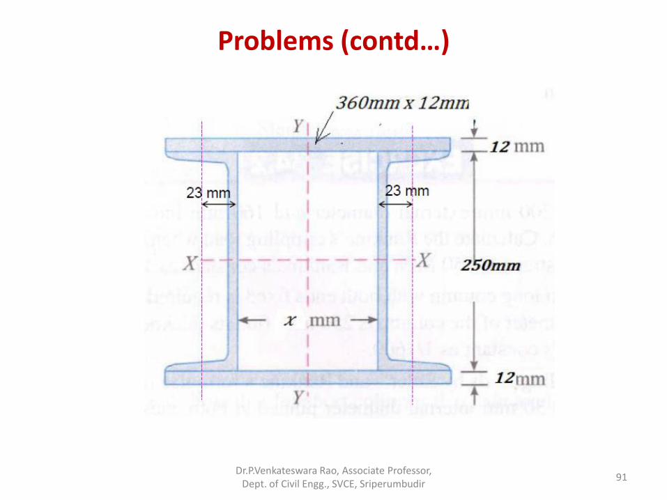
• Problem 7: A compound stanchion is made up of two ISMC 250 placed back to back with a gap between adjacent flat surfaces. Two 360 mm x 12 mm plates are riveted to the flanges, so as to form a symmetrical box section. Detremine the amount of gap if the column is to carry the maximum load. Properties of one ISMC 250 are:
Area = 3867 mm2,
Max MI (𝐼𝑥𝑥1) = 3816.1× 104𝑚𝑚4
Max MI (𝐼𝑦𝑦1) = 219.1× 10⁴𝑚𝑚4
Distance of the centroid from the back = 23 mm.
Dr.P.Venkateswara Rao, Associate Professor, Dept. of Civil Engg., SVCE, Sriperumbudir
89
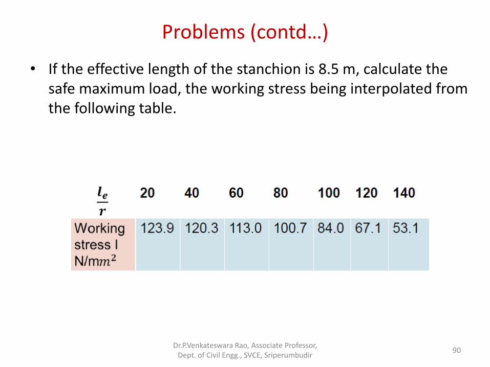
Problems (contd…)
• If the effective length of the stanchion is 8.5 m, calculate the safe maximum load, the working stress being interpolated from the following table.
Dr.P.Venkateswara Rao, Associate Professor, Dept. of Civil Engg., SVCE, Sriperumbudir
90
Problems (contd…)
Dr.P.Venkateswara Rao, Associate Professor, Dept. of Civil Engg., SVCE, Sriperumbudir
91
Problems (contd…)
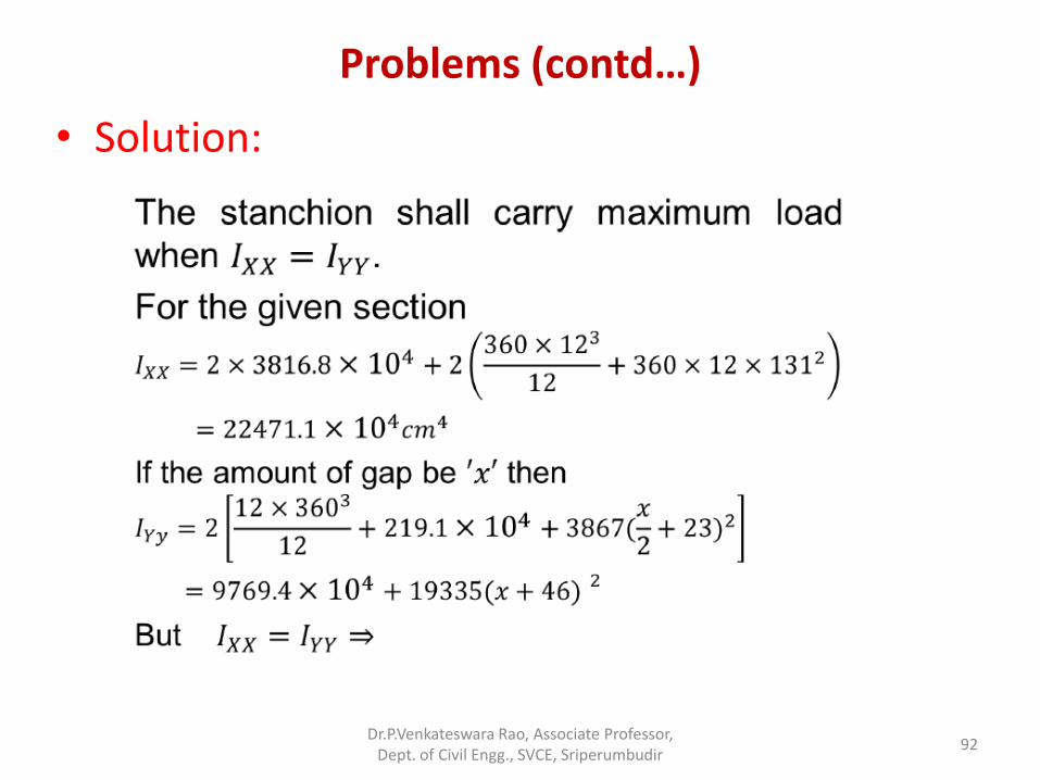
• Solution:
Dr.P.Venkateswara Rao, Associate Professor, Dept. of Civil Engg., SVCE, Sriperumbudir
92
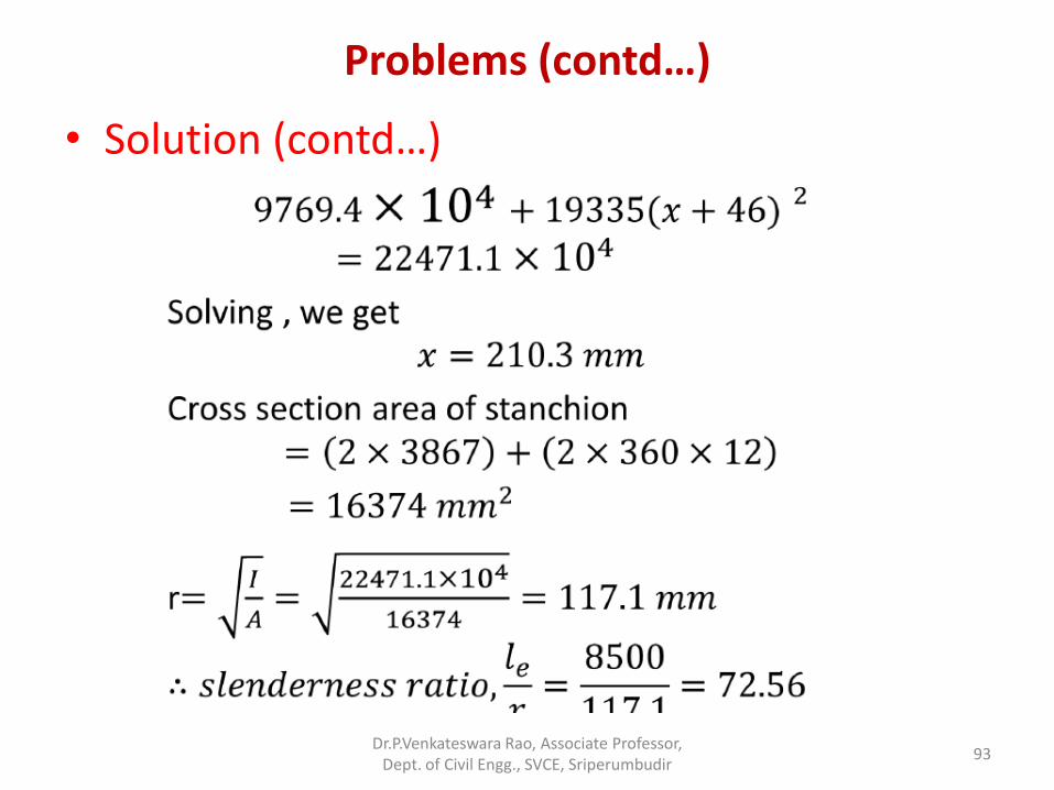
Problems (contd…)
• Solution (contd…)
Dr.P.Venkateswara Rao, Associate Professor, Dept. of Civil Engg., SVCE, Sriperumbudir
93
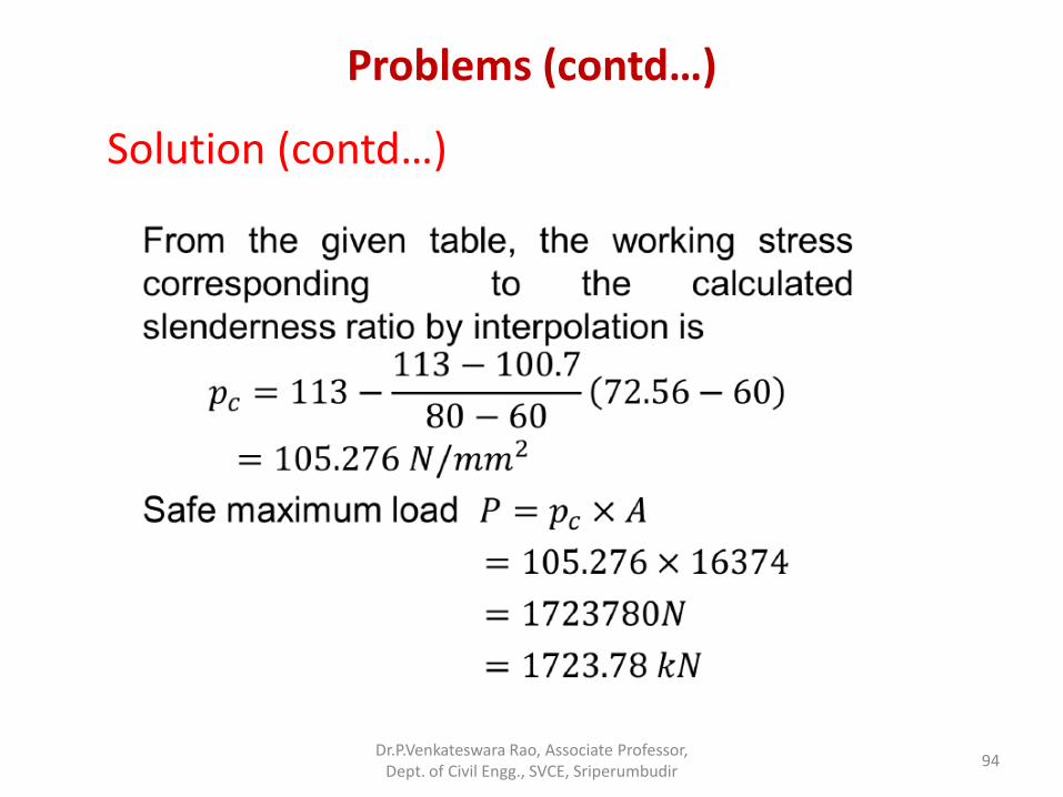
Problems (contd…)
Solution (contd…)
Dr.P.Venkateswara Rao, Associate Professor, Dept. of Civil Engg., SVCE, Sriperumbudir
94
Short Columns
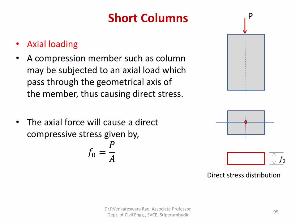
• Axial loading
• A compression member such as column may be subjected to an axial load which pass through the geometrical axis of the member, thus causing direct stress.
• The axial force will cause a direct compressive stress given by,
𝑓0 =𝑃
𝐴
Dr.P.Venkateswara Rao, Associate Professor, Dept. of Civil Engg., SVCE, Sriperumbudir
95
𝑓0
Direct stress distribution
P
Short Columns
• Eccentric Loading:
• Some times a compression member such as column may be subjected to an axial load which may not pass through the geometrical axis of the member, thus causing bending as well as direct stress.
• In all such cases position of neutral layer change or altogether vanishes.
• The axial force will cause a direct compressive stress given by,
• 𝑓0 =𝑃
𝐴
• The bending couple will cause longitudinal tensile and compressive stresses.
Dr.P.Venkateswara Rao, Associate Professor, Dept. of Civil Engg., SVCE, Sriperumbudir
96
Short Columns
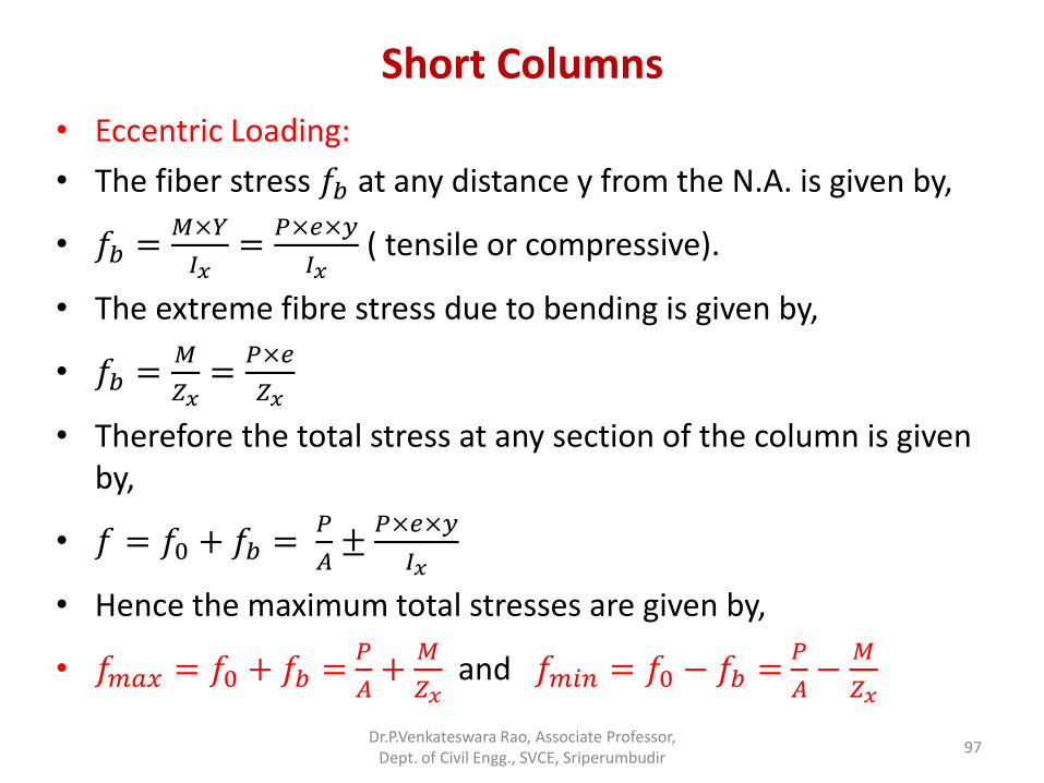
• Eccentric Loading:
• The fiber stress 𝑓𝑏 at any distance y from the N.A. is given by,
• 𝑓𝑏 =𝑀×𝑌
𝐼𝑥=
𝑃×𝑒×𝑦
𝐼𝑥 ( tensile or compressive).
• The extreme fibre stress due to bending is given by,
• 𝑓𝑏 =𝑀
𝑍𝑥=
𝑃×𝑒
𝑍𝑥
• Therefore the total stress at any section of the column is given by,
• 𝑓 = 𝑓0 + 𝑓𝑏 = 𝑃
𝐴±
𝑃×𝑒×𝑦
𝐼𝑥
• Hence the maximum total stresses are given by,
• 𝑓𝑚𝑎𝑥 = 𝑓0 + 𝑓𝑏 = 𝑃
𝐴+
𝑀
𝑍𝑥 and 𝑓𝑚𝑖𝑛 = 𝑓0 − 𝑓𝑏 =
𝑃
𝐴−
𝑀
𝑍𝑥
Dr.P.Venkateswara Rao, Associate Professor, Dept. of Civil Engg., SVCE, Sriperumbudir
97
Short Columns
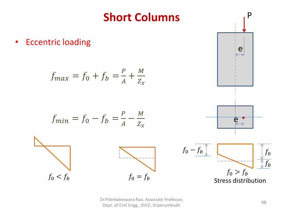
• Eccentric loading
Dr.P.Venkateswara Rao, Associate Professor, Dept. of Civil Engg., SVCE, Sriperumbudir
98
e
e
𝑓𝑚𝑎𝑥 = 𝑓0 + 𝑓𝑏 = 𝑃
𝐴+
𝑀
𝑍𝑥
𝑓𝑚𝑖𝑛 = 𝑓0 − 𝑓𝑏 = 𝑃
𝐴−
𝑀
𝑍𝑥
𝑓0
Stress distribution
𝑓𝑏
𝑓0 − 𝑓𝑏
𝑓0 > 𝑓𝑏 𝑓0 < 𝑓𝑏 𝑓0 = 𝑓𝑏
P
Short Columns
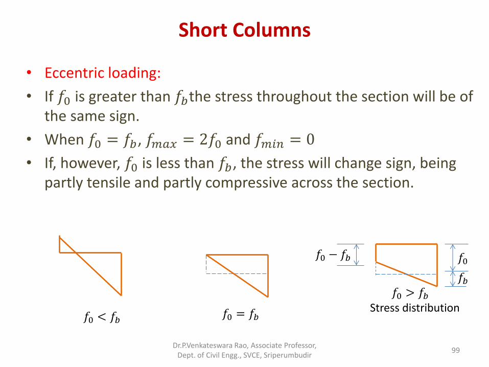
• Eccentric loading:
• If 𝑓0 is greater than 𝑓𝑏the stress throughout the section will be of the same sign.
• When 𝑓0 = 𝑓𝑏, 𝑓𝑚𝑎𝑥 = 2𝑓0 and 𝑓𝑚𝑖𝑛 = 0
• If, however, 𝑓0 is less than 𝑓𝑏, the stress will change sign, being partly tensile and partly compressive across the section.
Dr.P.Venkateswara Rao, Associate Professor, Dept. of Civil Engg., SVCE, Sriperumbudir
99
𝑓0 < 𝑓𝑏 𝑓0 = 𝑓𝑏
𝑓0
Stress distribution
𝑓𝑏
𝑓0 − 𝑓𝑏
𝑓0 > 𝑓𝑏
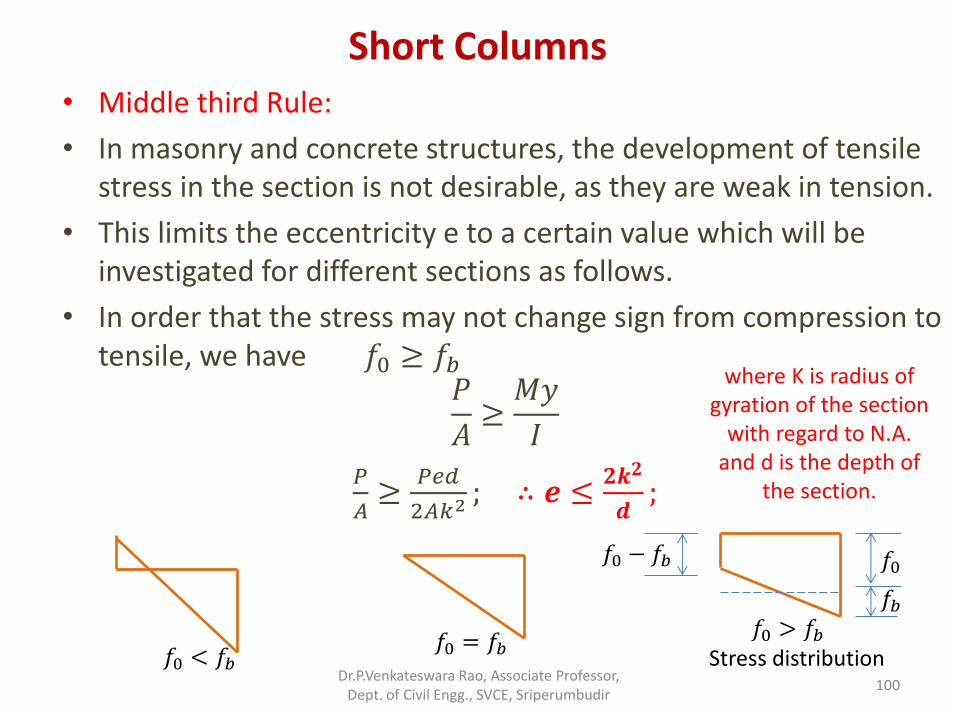
Short Columns • Middle third Rule:
• In masonry and concrete structures, the development of tensile stress in the section is not desirable, as they are weak in tension.
• This limits the eccentricity e to a certain value which will be investigated for different sections as follows.
• In order that the stress may not change sign from compression to tensile, we have 𝑓0 ≥ 𝑓𝑏
𝑃
𝐴≥𝑀𝑦
𝐼
𝑃
𝐴≥
𝑃𝑒𝑑
2𝐴𝑘2; ∴ 𝒆 ≤
𝟐𝒌𝟐
𝒅;
Dr.P.Venkateswara Rao, Associate Professor, Dept. of Civil Engg., SVCE, Sriperumbudir
100
𝑓0 = 𝑓𝑏 𝑓0 < 𝑓𝑏
𝑓0
Stress distribution
𝑓𝑏
𝑓0 − 𝑓𝑏
𝑓0 > 𝑓𝑏
where K is radius of gyration of the section
with regard to N.A. and d is the depth of
the section.
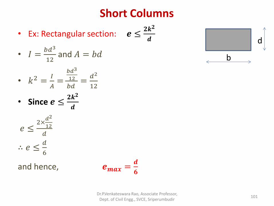
Short Columns
• Ex: Rectangular section: 𝒆 ≤𝟐𝒌𝟐
𝒅
• 𝐼 =𝑏𝑑3
12 and 𝐴 = 𝑏𝑑
• 𝑘2 =𝐼
𝐴=
𝑏𝑑3
12
𝑏𝑑 =
𝑑2
12
• Since 𝒆 ≤𝟐𝒌𝟐
𝒅
𝑒 ≤2×
𝑑2
12
𝑑
∴ 𝑒 ≤𝑑
6
and hence, 𝒆𝒎𝒂𝒙 =𝒅
𝟔
Dr.P.Venkateswara Rao, Associate Professor, Dept. of Civil Engg., SVCE, Sriperumbudir
101
b
d
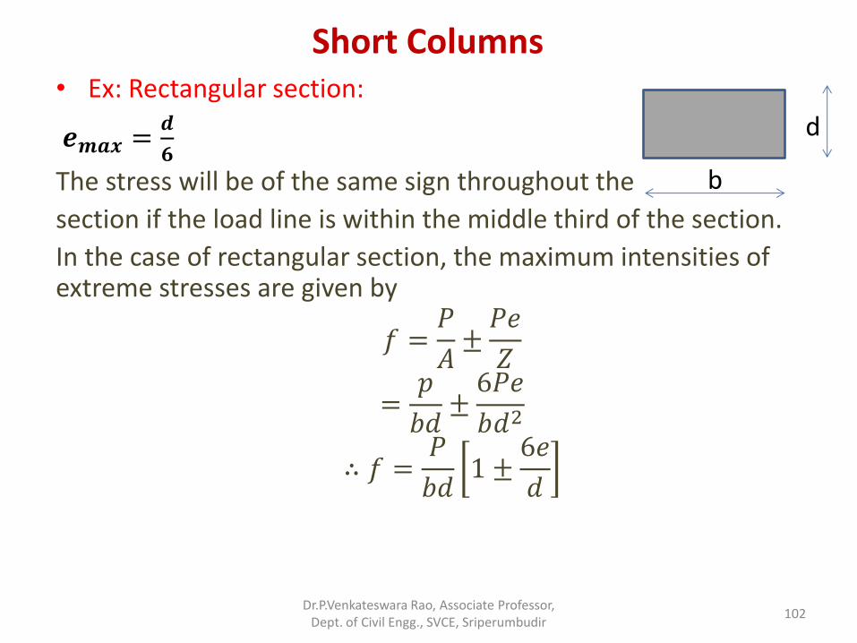
Short Columns • Ex: Rectangular section:
𝒆𝒎𝒂𝒙 =𝒅
𝟔
The stress will be of the same sign throughout the
section if the load line is within the middle third of the section.
In the case of rectangular section, the maximum intensities of extreme stresses are given by
𝑓 =𝑃
𝐴±𝑃𝑒
𝑍
=𝑝
𝑏𝑑±6𝑃𝑒
𝑏𝑑2
∴ 𝑓 =𝑃
𝑏𝑑1 ±
6𝑒
𝑑
Dr.P.Venkateswara Rao, Associate Professor, Dept. of Civil Engg., SVCE, Sriperumbudir
102
b
d
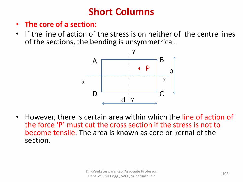
Short Columns • The core of a section: • If the line of action of the stress is on neither of the centre lines
of the sections, the bending is unsymmetrical.
• However, there is certain area within which the line of action of the force ‘P’ must cut the cross section if the stress is not to become tensile. The area is known as core or kernal of the section.
Dr.P.Venkateswara Rao, Associate Professor, Dept. of Civil Engg., SVCE, Sriperumbudir
103
x
y
A B
D C d
b x
y
P
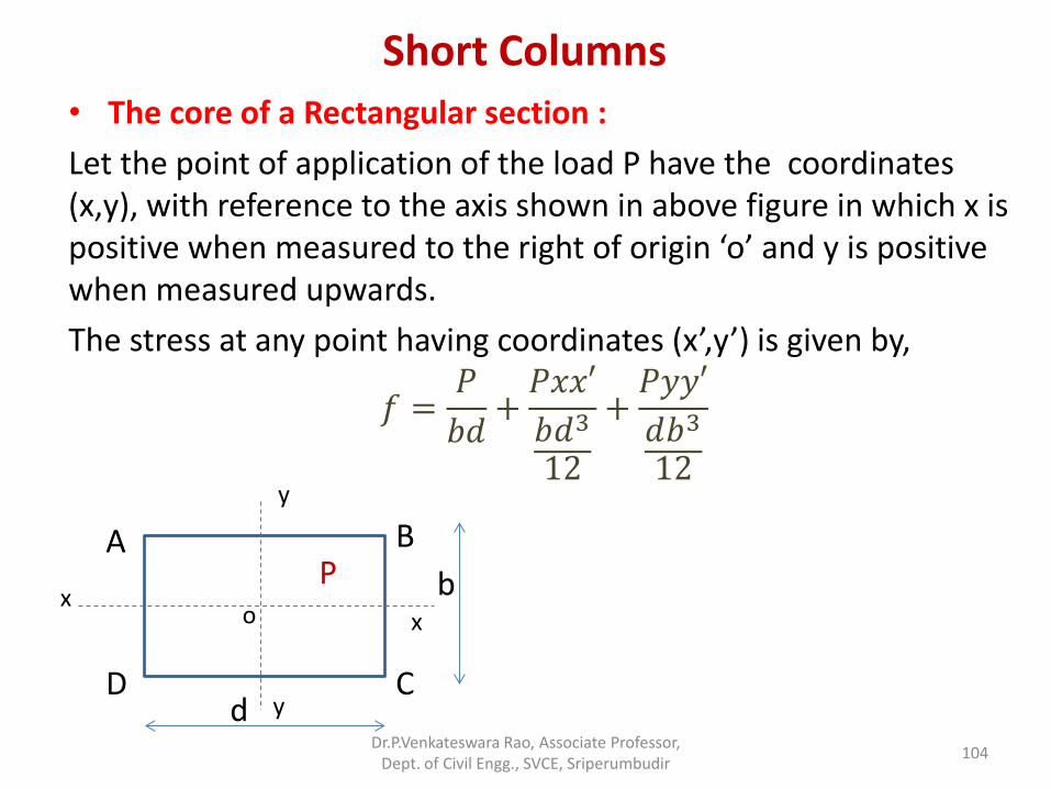
Short Columns • The core of a Rectangular section :
Let the point of application of the load P have the coordinates (x,y), with reference to the axis shown in above figure in which x is positive when measured to the right of origin ‘o’ and y is positive when measured upwards.
The stress at any point having coordinates (x’,y’) is given by,
𝑓 =𝑃
𝑏𝑑+𝑃𝑥𝑥′
𝑏𝑑3
12
+𝑃𝑦𝑦′
𝑑𝑏3
12
Dr.P.Venkateswara Rao, Associate Professor, Dept. of Civil Engg., SVCE, Sriperumbudir
104
x
y
A B
D C d
b x
y
P o
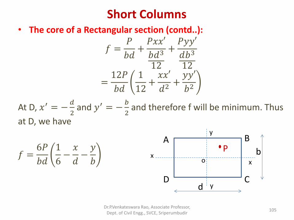
Short Columns • The core of a Rectangular section (contd..):
𝑓 =𝑃
𝑏𝑑+𝑃𝑥𝑥′
𝑏𝑑3
12
+𝑃𝑦𝑦′
𝑑𝑏3
12
=12𝑃
𝑏𝑑
1
12+𝑥𝑥′
𝑑2+𝑦𝑦′
𝑏2
At D, 𝑥′ = −𝑑
2 and 𝑦′ = −
𝑏
2 and therefore f will be minimum. Thus
at D, we have
𝑓 =6𝑃
𝑏𝑑
1
6−𝑥
𝑑−𝑦
𝑏
Dr.P.Venkateswara Rao, Associate Professor, Dept. of Civil Engg., SVCE, Sriperumbudir
105
y
x
A B
D C d
b x
y
P o
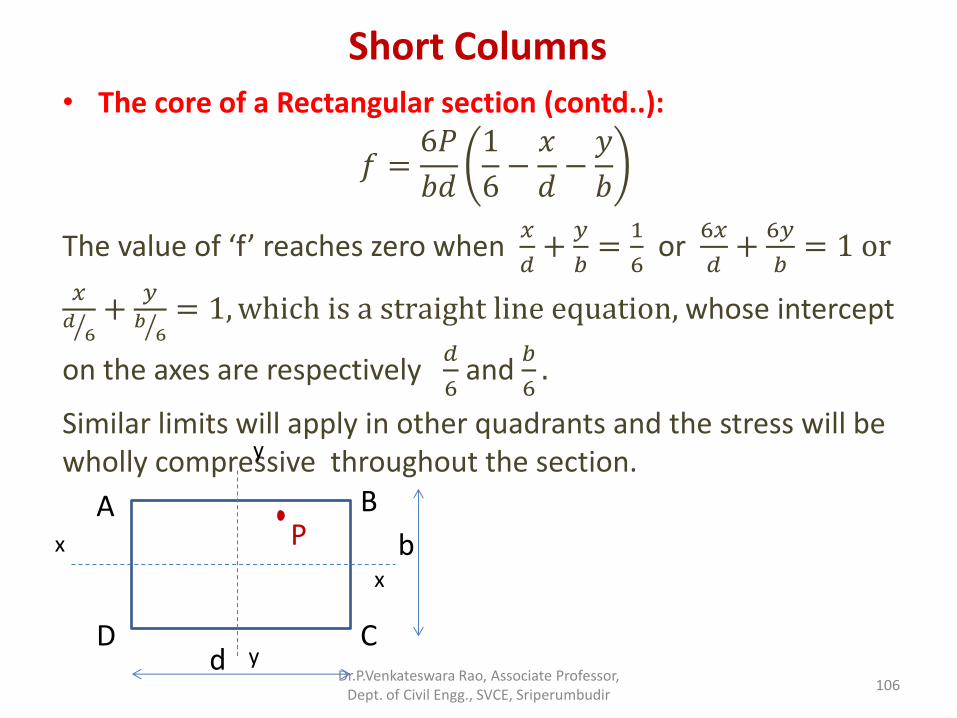
Short Columns • The core of a Rectangular section (contd..):
𝑓 =6𝑃
𝑏𝑑
1
6−𝑥
𝑑−𝑦
𝑏
The value of ‘f’ reaches zero when 𝑥
𝑑+
𝑦
𝑏=
1
6 or
6𝑥
𝑑+
6𝑦
𝑏= 1 or
𝑥𝑑
6 +
𝑦𝑏
6 = 1,which is a straight line equation, whose intercept
on the axes are respectively 𝑑
6 and
𝑏
6.
Similar limits will apply in other quadrants and the stress will be wholly compressive throughout the section.
Dr.P.Venkateswara Rao, Associate Professor, Dept. of Civil Engg., SVCE, Sriperumbudir
106
x
y
A B
D C d
b x
y
P
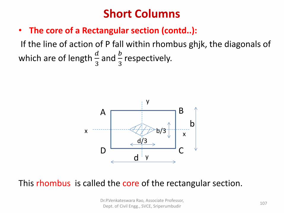
Short Columns • The core of a Rectangular section (contd..):
If the line of action of P fall within rhombus ghjk, the diagonals of
which are of length 𝑑
3 and
𝑏
3 respectively.
This rhombus is called the core of the rectangular section.
Dr.P.Venkateswara Rao, Associate Professor, Dept. of Civil Engg., SVCE, Sriperumbudir
107
y
A B
D C d
b x
y
x
d/3
b/3
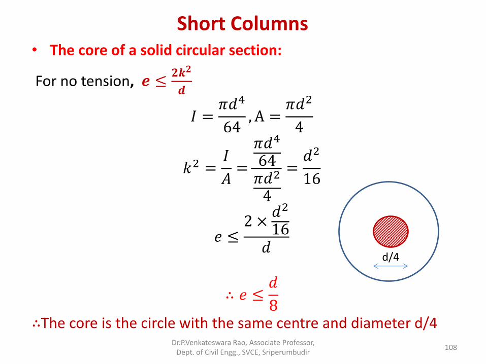
Short Columns • The core of a solid circular section:
For no tension, 𝒆 ≤𝟐𝒌𝟐
𝒅
𝐼 =𝜋𝑑4
64, A =
𝜋𝑑2
4
𝑘2 =𝐼
𝐴=
𝜋𝑑4
64𝜋𝑑2
4
=𝑑2
16
𝑒 ≤2 ×
𝑑2
16𝑑
∴ 𝑒 ≤𝑑
8
∴The core is the circle with the same centre and diameter d/4 Dr.P.Venkateswara Rao, Associate Professor,
Dept. of Civil Engg., SVCE, Sriperumbudir 108
d/4
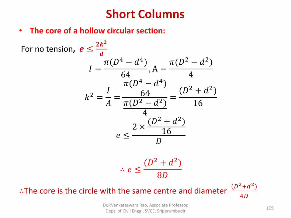
Short Columns • The core of a hollow circular section:
For no tension, 𝒆 ≤𝟐𝒌𝟐
𝒅
𝐼 =𝜋(𝐷4 − 𝑑4)
64, A =
𝜋(𝐷2 − 𝑑2)
4
𝑘2 =𝐼
𝐴=
𝜋(𝐷4 − 𝑑4)64
𝜋(𝐷2 − 𝑑2)4
=(𝐷2 + 𝑑2)
16
𝑒 ≤2 ×
(𝐷2 + 𝑑2)16
𝐷
∴ 𝑒 ≤(𝐷2 + 𝑑2)
8𝐷
∴The core is the circle with the same centre and diameter (𝐷2+𝑑2)
4𝐷
Dr.P.Venkateswara Rao, Associate Professor, Dept. of Civil Engg., SVCE, Sriperumbudir
109
A.U. Question Paper Problems
• State the Euler’s assumption in column theory. And derive a relation for the Euler’s crippling load for a columns with both ends hinged (Nov/Dec 2014).
Dr.P.Venkateswara Rao, Associate Professor, Dept. of Civil Engg., SVCE, Sriperumbudir
110
A.U. Question Paper Problems
• A short length of tube having Internal diameter and external diameter are 4 cm and 5 cm respectively, which failed in compression at a load of 250 kN. When a 1.8 m length of the same tube was tested as a strut with fixed ends, the load failure was 160 kN. Assuming that 𝜎𝑐 in Rankin’s formula is given by the first test, find the value of the constant 𝛼 in the same formula. What will be the crippling load of this tube if it is used as a strut 2.8 m long with one end fixed and the other hinged? (Nov/Dec 2014)
Dr.P.Venkateswara Rao, Associate Professor, Dept. of Civil Engg., SVCE, Sriperumbudir
111
2 marks questions and Answers
1. State the middle third rule?
2. What is known as crippling load?
Dr.P.Venkateswara Rao, Associate Professor, Dept. of Civil Engg., SVCE, Sriperumbudir
112