Embed Size (px)
Citation preview

UNIT IV IMAGE SEGMENTATION
1. What is segmentation? [AUC APR/MAY 2012]
Segmentation subdivides on image in to its constitute regions or objects. The level to which the
subdivides is carried depends on the problem being solved .That is segmentation should when the
objects of interest in application have been isolated.
2. Write the applications of segmentation.
* Detection of isolated points.
* Detection of lines and edges in an image.
3. What are the three types of discontinuity in digital image?[AUC NOV /DEC 2013]
Points, lines and edges.
4. How the derivatives are obtained in edge detection during formulation?
The first derivative at any point in an image is obtained by using the magnitude of
the gradient at that point. Similarly the second derivatives are obtained by using the laplacian.
5. Write about linking edge points.
The approach for linking edge points is to analyze the characteristics of pixels in a
small neighborhood (3x3 or 5x5) about every point (x,y)in an image that has undergone edge
detection. All points that are similar are linked, forming a boundary of pixels that share some
common properties.
6. What are the two properties used for establishing similarity of edge pixels?
(1) The strength of the response of the gradient operator used to produce the edge
pixel.
(2) The direction of the gradient.
7. What is edge?
An edge isa set of connected pixels that lie on the boundary between two regions
edges are more closely modeled as having a ramplike profile. The slope of the ramp is inversely
proportional to the degree of blurring in the edge.
8. Give the properties of the second derivative around an edge?
* The sign of the second derivative can be used to determine whether an edge
pixel lies on the dark or light side of an edge.
* It produces two values for every edge in an image.
* An imaginary straightline joining the extreme positive and negative values of
the second derivative would cross zero near the midpoint of the edge.
9. Define Gradient Operator? [AUC APR/MAY 2009]
First order derivatives of a digital image are based on various approximation of
the 2-D gradient. The gradient of an image f(x,y) at location(x,y) is defined as the
vector
Magnitude of the vector is
_f=mag( _f )=[Gx2+ Gy2]1/2
_(x,y)=tan-1(Gy/Gx)
_(x,y) is the direction angle of vector _f
10. What is meant by object point and background point?
To execute the objects from the background is to select a threshold T that separate these modes.
Then any point (x,y) for which f(x,y)>T is called an object point. Otherwise the point is called
background point.

11. What is global, Local and dynamic or adaptive threshold?
When Threshold T depends only on f(x,y) then the threshold is called global . If T
depends both on f(x,y) and p(x,y) is called local. If T depends on the spatial coordinates x and y
the threshold is called dynamic or adaptive where f(x,y) is the original image.
12. Define region growing? [AUC APR/MAY 2010]
Region growing is a procedure that groups pixels or subregions in to layer regions based on
predefined criteria. The basic approach is to start with a set of seed points and from there grow
regions by appending to each seed these neighbouring pixels that have properties similar to the
seed.
13. Specify the steps involved in splitting and merging?
Split into 4 disjoint quadrants any region Ri for which P(Ri)=FALSE.
Merge any adjacent regions Rj and Rk for which P(RjURk)=TRUE.
Stop when no further merging or splitting is positive.
14. What is meant by markers?
An approach used to control over segmentation is based on markers.
marker is a connected component belonging to an image. We have internal markers, associated
with objects of interest and external markers associated with background.
15. What are the 2 principles steps involved in marker selection?
The two steps are
1. Preprocessing
2. Definition of a set of criteria that markers must satisfy.
16. Define chain codes?
Chain codes are used to represent a boundary by a connected sequence of
straight line segment of specified length and direction. Typically this representation is based on 4
or 8 connectivity of the segments . The direction of each segment is coded by using a numbering
scheme.
17. What are the demerits of chain code?
* The resulting chain code tends to be quite long.
* Any small disturbance along the boundary due to noise cause changes in the code
that may not be related to the shape of the boundary.
18. What is thinning or skeletonizing algorithm?
An important approach to represent the structural shape of a plane region is to
reduce it to a graph. This reduction may be accomplished by obtaining the
skeletonizing algorithm. It play a central role in a broad range of problems in image
processing, ranging from automated inspection of printed circuit boards to counting
of asbestos fibres in air filter.
19. Specify the various image representation approaches
20. What is polygonal approximation method ?
Polygonal approximation is a image representation approach in which a digital
boundary can be approximated with arbitary accuracy by a polygon.For a closed curve the
approximation is exact when the number of segments in polygon is equal to the number of points
in the boundary so that each pair of adjacent points defines a segment in the polygon.

21. Specify the various polygonal approximation methods
22. Name few boundary descriptors
numbers
23. Give the formula for diameter of boundary
The diameter of a boundary B is defined as
Diam(B)=max[D(pi,pj)]
i,j D-distance measure
pi,pj-points on the boundary
24. Define length of a boundary. [AUC APR/MAY 2009]
The length of a boundary is the number of pixels along a boundary.Eg.for a chain
coded curve with unit spacing in both directions the number of vertical and horizontal components
plus _2 times the number of diagonal components gives its exact length.
25. Define eccentricity and curvature of boundary
Eccentricity of boundary is the ratio of the major axis to minor axis.
Curvature is the rate of change of slope.
26. Define shape numbers
Shape number is defined as the first difference of smallest magnitude. The order n of a shape
number is the number of digits in its representation.
27. Describe Fourier descriptors
Fourier descriptor of a boundary can be defined as
K-1
a(u)=1/K_s(k)e-j2_uk/K
k=0
for u=0,1,2……K-1.The complex coefficients a(u) are called Fourier descriptor
of a boundary.
The inverse Fourier descriptor is
K-1
s(k)= _ a(u)ej2_uk/K
u=0
for k=0,1,2,……K-1
28. Give the Fourier descriptors for the following transformations
(1)Identity (2)Rotation (3)Translation (4)Scaling (5)Starting point
(1)Identity – a(u)
(2)Rotation -ar(u)= a(u)ej_
(3) Translation-at(u)=a(u)+_xy_(u)
(4)Scaling-as(u)=_a(u)
(5)Starting point-ap(u)=a(u)e-j2_uk0/K
29. Specify the types of regional descriptors
30. Name few measures used as simple descriptors in region descriptors

31. Define compactness
Compactness of a region is defined as (perimeter)^2/area. It is a dimensionless quantity and is
insensitive to uniform scale changes.
32. Describe texture
Texture is one of the regional descriptors. It provides measures of
properties such as smoothness, coarseness and regularity. There are 3 approaches used to
describe texture of a region.
They are:
33. Describe statistical approach[AUC APR/MAY 2012]
Statistical approaches describe smooth,coarse,grainy characteristics of
texture.This is the simplest one compared to others.It describes texture using statistical moments
of the gray-level histogram of an image or region.
34. Define gray-level co-occurrence matrix.
A matrix C is formed by dividing every element of A by n(A is a k x k matrix and n is the total
number of point pairs in the image satisfying P(position operator). The matrix C is called gray-
level co-occurrence matrix if C depends on P,the presence of given texture patterns may be
detected by choosing an appropriate position operator.
35. Explain structural and spectral approach [AUC NOV /DEC 2013]
Structural approach deals with the arrangement of image primitives such as description of texture
based on regularly spaced parallel lines.
Spectral approach is based on properties of the Fourier spectrum and are primarily to detect global
periodicity in an image by identifying high energy, narrow peaks in spectrum.There are 3 features
of Fourier spectrum that are useful for texture description.
They are:
ncipal direction of texture patterns.
patterns.
- periodic
image elements.

Digital Image Processing Question & Answers
1. What are the derivative operators useful in image segmentation? Explain
their role in segmentation. [AUC NOV /DEC 2013]
Gradient operators:
First-order derivatives of a digital image are based on various approximations of the 2-D
gradient. The gradient of an image f (x, y) at location (x, y) is defined as the vector
It is well known from vector analysis that the gradient vector points in the direction of maximum
rate of change of f at coordinates (x, y). An important quantity in edge detection is the magnitude
of this vector, denoted by f, where
This quantity gives the maximum rate of increase of f (x, y) per unit distance in the direction of f. It is a common (although not strictly correct) practice to refer to f also as the gradient. The
direction of the gradient vector also is an important quantity. Let α (x, y) represent the direction
angle of the vector f at (x, y). Then, from vector analysis,
where the angle is measured with respect to the x-axis. The direction of an edge at (x, y) is
perpendicular to the direction of the gradient vector at that point. Computation of the gradient of
an image is based on obtaining the partial derivatives f/ x and f/ y at every pixel location. Let the
3x3 area shown in Fig. 1.1 (a) represent the gray levels in a neighborhood of an image. One of the
simplest ways to implement a first-order partial derivative at point z5 is to use the following
Roberts cross-gradient operators:

Digital Image Processing Question & Answers
These derivatives can be implemented for an entire image by using the masks shown in Fig.
1.1(b). Masks of size 2 X 2 are awkward to implement because they do not have a clear center. An
approach using masks of size 3 X 3 is given by
Fig.1.1 A 3 X 3 region of an image (the z’s are gray-level values) and various masks used to
compute the gradient at point labeled z5.

Digital Image Processing Question & Answers
A weight value of 2 is used to achieve some smoothing by giving more importance to the center
point. Figures 1.1(f) and (g), called the Sobel operators, and are used to implement these two
equations. The Prewitt and Sobel operators are among the most used in practice for computing
digital gradients. The Prewitt masks are simpler to implement than the Sobel masks, but the latter
have slightly superior noise-suppression characteristics, an important issue when dealing with
derivatives. Note that the coefficients in all the masks shown in Fig. 1.1 sum to 0, indicating that
they give a response of 0 in areas of constant gray level, as expected of a derivative operator.
The masks just discussed are used to obtain the gradient components Gx and Gy. Computation of
the gradient requires that these two components be combined. However, this implementation is
not always desirable because of the computational burden required by squares and square roots.
An approach used frequently is to approximate the gradient by absolute values:
This equation is much more attractive computationally, and it still preserves relative changes in
gray levels. However, this is not an issue when masks such as the Prewitt and Sobel masks are
used to compute Gx and Gy.
It is possible to modify the 3 X 3 masks in Fig. 1.1 so that they have their strongest responses
along the diagonal directions. The two additional Prewitt and Sobel masks for detecting
discontinuities in the diagonal directions are shown in Fig. 1.2.

Digital Image Processing Question & Answers
Fig.1.2 Prewitt and Sobel masks for detecting diagonal edges
The Laplacian:
The Laplacian of a 2-D function f(x, y) is a second-order derivative defined as
For a 3 X 3 region, one of the two forms encountered most frequently in practice is
Fig.1.3 Laplacian masks used to implement Eqns. above.

Digital Image Processing Question & Answers
where the z's are defined in Fig. 1.1(a). A digital approximation including the diagonal neighbors
is given by
Masks for implementing these two equations are shown in Fig. 1.3. We note from these masks that
the implementations of Eqns. are isotropic for rotation increments of 90° and 45°, respectively.
2. Write about edge detection. [AUC APR/MAY 2012]
Intuitively, an edge is a set of connected pixels that lie on the boundary between two regions.
Fundamentally, an edge is a "local" concept whereas a region boundary, owing to the way it is
defined, is a more global idea. A reasonable definition of "edge" requires the ability to measure
gray-level transitions in a meaningful way. We start by modeling an edge intuitively. This will
lead us to formalism in which "meaningful" transitions in gray levels can be measured. Intuitively,
an ideal edge has the properties of the model shown in Fig. 2.1(a). An ideal edge according to this
model is a set of connected pixels (in the vertical direction here), each of which is located at an
orthogonal step transition in gray level (as shown by the horizontal profile in the figure).
In practice, optics, sampling, and other image acquisition imperfections yield edges that
are blurred, with the degree of blurring being determined by factors such as the quality of the
image acquisition system, the sampling rate, and illumination conditions under which the image is
acquired. As a result, edges are more closely modeled as having a "ramp like" profile, such as the
one shown in Fig.2.1 (b).

Digital Image Processing Question & Answers
Fig.2.1 (a) Model of an ideal digital edge (b) Model of a ramp edge. The slope of the ramp is
proportional to the degree of blurring in the edge.
The slope of the ramp is inversely proportional to the degree of blurring in the edge. In this model,
we no longer have a thin (one pixel thick) path. Instead, an edge point now is any point contained
in the ramp, and an edge would then be a set of such points that are connected. The "thickness" of
the edge is determined by the length of the ramp, as it transitions from an initial to a final gray
level. This length is determined by the slope, which, in turn, is determined by the degree of
blurring. This makes sense: Blurred edges lend to be thick and sharp edges tend to be thin. Figure
2.2(a) shows the image from which the close-up in Fig. 2.1(b) was extracted. Figure 2.2(b) shows
a horizontal gray-level profile of the edge between the two regions. This figure also shows the first
and second derivatives of the gray-level profile. The first derivative is positive at the points of
transition into and out of the ramp as we move from left to right along the profile; it is constant for
points in the ramp; and is zero in areas of constant gray level. The second derivative is positive at
the transition associated with the dark side of the edge, negative at the transition associated with
the light side of the edge, and zero along the ramp and in areas of constant gray level. The signs of
the derivatives in Fig. 2.2(b) would be reversed for an edge that transitions from light to dark.
We conclude from these observations that the magnitude of the first derivative can be used to
detect the presence of an edge at a point in an image (i.e. to determine if a point is on a ramp).
Similarly, the sign of the second derivative can be used to determine whether an edge pixel lies

Digital Image Processing Question & Answers
on the dark or light side of an edge. We note two additional properties of the second derivative
around an edge: A) It produces two values for every edge in an image (an undesirable feature);
and B) an imaginary straight line joining the extreme positive and negative values of the second
derivative would cross zero near the midpoint of the edge. This zero-crossing property of the
second derivative is quite useful for locating the centers of thick edges.
Fig.2.2 (a) Two regions separated by a vertical edge (b) Detail near the edge, showing a gray-
level profile, and the first and second derivatives of the profile.

Digital Image Processing Question & Answers
3. Explain about the edge linking procedures.
The different methods for edge linking are as follows
(i) Local processing
(ii) Global processing via the Hough Transform
(iii) Global processing via graph-theoretic techniques.
(i) Local Processing:
One of the simplest approaches for linking edge points is to analyze the characteristics of pixels in
a small neighborhood (say, 3 X 3 or 5 X 5) about every point (x, y) in an image that has been
labeled an edge point. All points that are similar according to a set of predefined criteria are
linked, forming an edge of pixels that share those criteria.
The two principal properties used for establishing similarity of edge pixels in this kind of analysis
are (1) the strength of the response of the gradient operator used to produce the edge pixel; and (2)
the direction of the gradient vector. The first property is given by the value of f.
Thus an edge pixel with coordinates (xo, yo) in a predefined neighborhood of (x, y), is similar in
magnitude to the pixel at (x, y) if
The direction (angle) of the gradient vector is given by Eq. An edge pixel at (xo, yo) in the
predefined neighborhood of (x, y) has an angle similar to the pixel at (x, y) if
where A is a nonnegative angle threshold. The direction of the edge at (x, y) is perpendicular to
the direction of the gradient vector at that point.
A point in the predefined neighborhood of (x, y) is linked to the pixel at (x, y) if both magnitude
and direction criteria are satisfied. This process is repeated at every location in the image. A
record must be kept of linked points as the center of the neighborhood is moved from pixel to
pixel. A simple bookkeeping procedure is to assign a different gray level to each set of linked edge
pixels.
Digital Image Processing Question & Answers
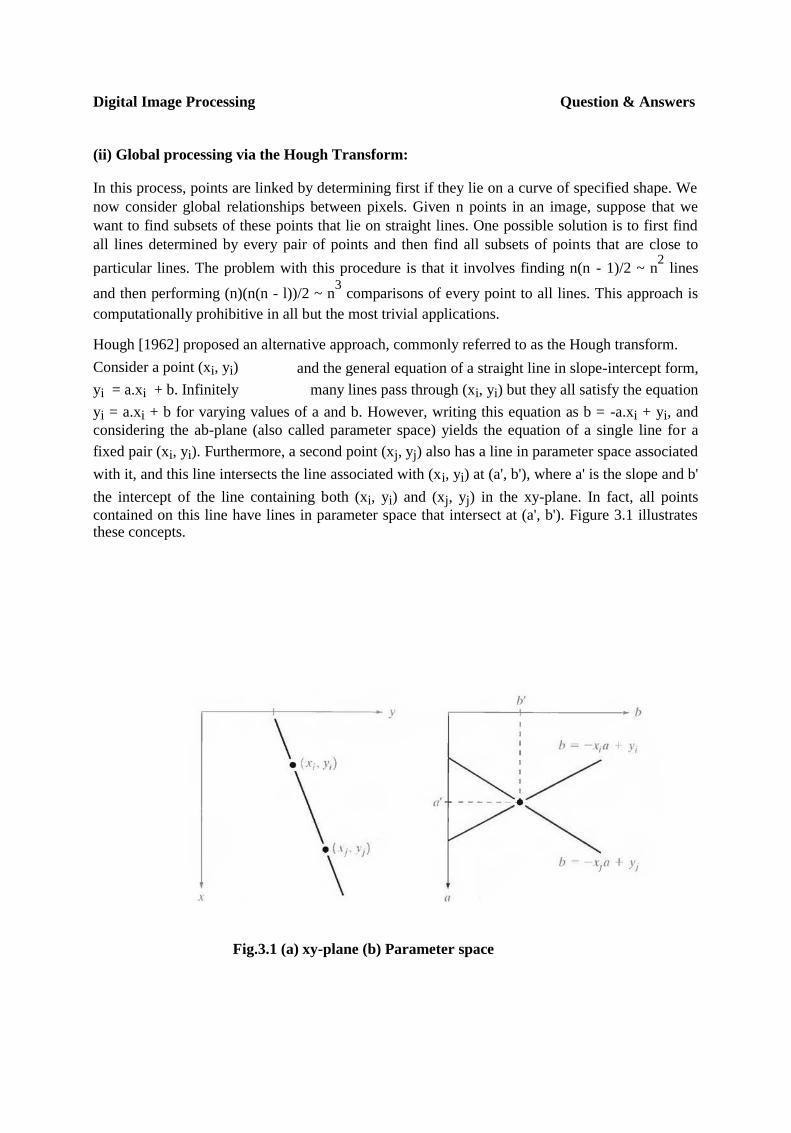
(ii) Global processing via the Hough Transform:
In this process, points are linked by determining first if they lie on a curve of specified shape. We
now consider global relationships between pixels. Given n points in an image, suppose that we
want to find subsets of these points that lie on straight lines. One possible solution is to first find
all lines determined by every pair of points and then find all subsets of points that are close to
particular lines. The problem with this procedure is that it involves finding n(n - 1)/2 ~ n2 lines
and then performing (n)(n(n - l))/2 ~ n3 comparisons of every point to all lines. This approach is
computationally prohibitive in all but the most trivial applications.
Hough [1962] proposed an alternative approach, commonly referred to as the Hough transform.
Consider a point (xi, yi) and the general equation of a straight line in slope-intercept form,
yi = a.xi + b. Infinitely many lines pass through (xi, yi) but they all satisfy the equation
yi = a.xi + b for varying values of a and b. However, writing this equation as b = -a.xi + yi, and
considering the ab-plane (also called parameter space) yields the equation of a single line for a
fixed pair (xi, yi). Furthermore, a second point (xj, yj) also has a line in parameter space associated
with it, and this line intersects the line associated with (xi, yi) at (a', b'), where a' is the slope and b'
the intercept of the line containing both (xi, yi) and (xj, yj) in the xy-plane. In fact, all points
contained on this line have lines in parameter space that intersect at (a', b'). Figure 3.1 illustrates these concepts.
Fig.3.1 (a) xy-plane (b) Parameter space

Digital Image Processing Question & Answers
Fig.3.2 Subdivision of the parameter plane for use in the Hough transform
The computational attractiveness of the Hough transform arises from subdividing the parameter
space into so-called accumulator cells, as illustrated in Fig. 3.2, where (amax , amin) and (bmax ,
bmin), are the expected ranges of slope and intercept values. The cell at coordinates (i, j), with
accumulator value A(i, j), corresponds to the square associated with parameter space coordinates
(ai , bi).
Initially, these cells are set to zero. Then, for every point (xk, yk) in the image plane, we let the
parameter a equal each of the allowed subdivision values on the fl-axis and solve for the
corresponding b using the equation b = - xk a + yk .The resulting b’s are then rounded off to the
nearest allowed value in the b-axis. If a choice of ap results in solution bq, we let A (p, q) = A (p,
q) + 1. At the end of this procedure, a value of Q in A (i, j) corresponds to Q points in the xy-plane
lying on the line y = ai x + bj. The number of subdivisions in the ab-plane determines the accuracy
of the co linearity of these points. Note that subdividing the a axis into K increments gives, for
every point (xk, yk), K values of b corresponding to the K possible values of a. With n image
points, this method involves nK computations. Thus the procedure just discussed is linear in n, and
the product nK does not approach the number of computations discussed at the beginning unless K
approaches or exceeds n.
A problem with using the equation y = ax + b to represent a line is that the slope
approaches infinity as the line approaches the vertical. One way around this difficulty is to use the
normal representation of a line:
x cosθ + y sinθ = ρ

Digital Image Processing Question & Answers
Figure 3.3(a) illustrates the geometrical interpretation of the parameters used. The use of this
representation in constructing a table of accumulators is identical to the method discussed for the
slope-intercept representation. Instead of straight lines, however, the loci are sinusoidal curves in
the ρθ -plane. As before, Q collinear points lying on a line x cosθj + y sinθj = ρ, yield Q
sinusoidal curves that intersect at (pi, θj) in the parameter space. Incrementing θ and solving for
the corresponding p gives Q entries in accumulator A (i, j) associated with the cell determined by
(pi, θj). Figure 3.3 (b) illustrates the subdivision of the parameter space.
Fig.3.3 (a) Normal representation of a line (b) Subdivision of the ρθ-plane into cells
The range of angle θ is ±90°, measured with respect to the x-axis. Thus with reference to Fig. 3.3
(a), a horizontal line has θ = 0°, with ρ being equal to the positive x-intercept. Similarly, a vertical
line has θ = 90°, with p being equal to the positive y-intercept, or θ = - 90°, with ρ being equal to
the negative y-intercept.
(iii) Global processing via graph-theoretic techniques
In this process we have a global approach for edge detection and linking based on representing
edge segments in the form of a graph and searching the graph for low-cost paths that correspond
to significant edges. This representation provides a rugged approach that performs well in the
presence of noise.

Digital Image Processing Question & Answers
Fig.3.4 Edge clement between pixels p and q
We begin the development with some basic definitions. A graph G = (N,U) is a finite, nonempty
set of nodes N, together with a set U of unordered pairs of distinct elements of N. Each pair (ni, nj)
of U is called an arc. A graph in which the arcs are directed is called a directed graph. If an arc is
directed from node ni to node nj, then nj is said to be a successor of the parent node ni. The
process of identifying the successors of a node is called expansion of the node. In each graph we define levels, such that level 0 consists of a single node, called the start or root node, and the
nodes in the last level are called goal nodes. A cost c (ni, n j) can be associated with every arc (ni,
nj). A sequence of nodes n1, n2... nk, with each node ni being a successor of node ni-1 is called a
path from n1 to nk. The cost of the entire path is
The following discussion is simplified if we define an edge element as the boundary between two
pixels p and q, such that p and q are 4-neighbors, as Fig.3.4 illustrates. Edge elements are
identified by the xy-coordinates of points p and q. In other words, the edge element in Fig. 3.4 is
defined by the pairs (xp, yp) (x q, yq). Consistent with the definition an edge is a sequence of
connected edge elements.
We can illustrate how the concepts just discussed apply to edge detection using the 3
X 3 image shown in Fig. 3.5 (a). The outer numbers are pixel

Digital Image Processing Question & Answers
Fig.3.5 (a) A 3 X 3 image region, (b) Edge segments and their costs, (c) Edge corresponding
to the lowest-cost path in the graph shown in Fig. 3.6
coordinates and the numbers in brackets represent gray-level values. Each edge element, defined
by pixels p and q, has an associated cost, defined as
where H is the highest gray-level value in the image (7 in this case), and f(p) and f(q) are the gray-
level values of p and q, respectively. By convention, the point p is on the right-hand side of the
direction of travel along edge elements. For example, the edge segment (1, 2) (2, 2) is between
points (1, 2) and (2, 2) in Fig. 3.5 (b). If the direction of travel is to the right, then p is the point
with coordinates (2, 2) and q is point with coordinates (1, 2); therefore, c (p, q) = 7 - [7 - 6] = 6.
This cost is shown in the box below the edge segment. If, on the other hand, we are traveling to
the left between the same two points, then p is point (1, 2) and q is (2, 2). In this case the cost is 8,
as shown above the edge segment in Fig. 3.5(b). To simplify the discussion, we assume that edges
start in the top row and terminate in the last row, so that the first element of an edge can be only
between points (1, 1), (1, 2) or (1, 2), (1, 3). Similarly, the last edge element has to be between
points (3, 1), (3, 2) or (3, 2), (3, 3). Keep in mind that p and q are 4-neighbors, as noted earlier.
Figure 3.6 shows the graph for this problem. Each node (rectangle) in the graph corresponds to an
edge element from Fig. 3.5. An arc exists between two nodes if the two corresponding edge
elements taken in succession can be part of an edge.

Digital Image Processing Question & Answers
Fig. 3.6 Graph for the image in Fig.3.5 (a). The lowest-cost path is shown dashed.
As in Fig. 3.5 (b), the cost of each edge segment, is shown in a box on the side of the arc leading
into the corresponding node. Goal nodes are shown shaded. The minimum cost path is shown
dashed, and the edge corresponding to this path is shown in Fig. 3.5 (c).

Digital Image Processing Question & Answers
4. What is thresholding? Explain about global thresholding. [AUC APR/MAY
2009,2012,2013]
Thresholding:
Because of its intuitive properties and simplicity of implementation, image thresholding enjoys a
central position in applications of image segmentation.
Global Thresholding:
The simplest of all thresholding techniques is to partition the image histogram by using a single
global threshold, T. Segmentation is then accomplished by scanning the image pixel by pixel and
labeling each pixel as object or back-ground, depending on whether the gray level of that pixel is
greater or less than the value of T. As indicated earlier, the success of this method depends
entirely on how well the histogram can be partitioned.
Fig.4.1 FIGURE 10.28 (a) Original image, (b) Image histogram, (c) Result of global
thresholding with T midway between the maximum and minimum gray levels.

Figure 4.1(a) shows a simple image, and Fig. 4.1(b) shows its histogram. Figure 4.1(c) shows the
result of segmenting Fig. 4.1(a) by using a threshold T midway between the maximum and
minimum gray levels. This threshold achieved a "clean" segmentation by eliminating the shadows
and leaving only the objects themselves. The objects of interest in this case are darker than the
background, so any pixel with a gray level ≤ T was labeled black (0), and any pixel with a gray
level ≥ T was labeled white (255).The key objective is merely to generate a binary image, so the
black-white relationship could be reversed. The type of global thresholding just described can be
expected to be successful in highly controlled environments. One of the areas in which this often
is possible is in industrial inspection applications, where control of the illumination usually is
feasible.The threshold in the preceding example was specified by using a heuristic approach,
based on visual inspection of the histogram. The following algorithm can be used to obtain T
automatically:
1. Select an initial estimate for T.
2. Segment the image using T. This will produce two groups of pixels: G1 consisting of all pixels
with gray level values >T and G2 consisting of pixels with values < T.
3. Compute the average gray level values µ1 and µ2 for the pixels in regions G1 and G2.
4. Compute a new threshold value:
5. Repeat steps 2 through 4 until the difference in T in successive iterations is smaller than a
predefined parameter To.
When there is reason to believe that the background and object occupy comparable areas in the
image, a good initial value for T is the average gray level of the image. When objects are small
compared to the area occupied by the background (or vice versa), then one group of pixels will
dominate the histogram and the average gray level is not as good an initial choice. A more
appropriate initial value for T in cases such as this is a value midway between the maximum and
minimum gray levels. The parameter To is used to stop the algorithm after changes become small
in terms of this parameter. This is used when speed of iteration is an important issue.
5. Explain about basic adaptive thresholding process used in image
segmentation. [AUC APR/MAY 2011]
Basic Adaptive Thresholding:
Imaging factors such as uneven illumination can transform a perfectly segmentable histogram
into a histogram that cannot be partitioned effectively by a single global threshold. An approach
for handling such a situation is to divide the original image into subimages and then utilize a
different threshold to segment each subimage. The key issues in this approach are how to
subdivide the image and how to estimate the threshold for each resulting subimage. Since the
threshold used for each pixel depends on the location of the pixel in terms of the subimages, this
type of thresholding is adaptive.

Fig.5 (a) Original image, (b) Result of global thresholding. (c) Image subdivided into
individual subimages (d) Result of adaptive thresholding.
We illustrate adaptive thresholding with a example. Figure 5(a) shows the image, which we
concluded could not be thresholded effectively with a single global threshold. In fact, Fig. 5(b)
shows the result of thresholding the image with a global threshold manually placed in the valley of
its histogram. One approach to reduce the effect of nonuniform illumination is to subdivide the
image into smaller subimages, such that the illumination of each subimage is approximately
uniform. Figure 5(c) shows such a partition, obtained by subdividing the image into four equal
parts, and then subdividing each part by four again. All the subimages that did not contain a
boundary between object and back-ground had variances of less than 75. All subimages containing
boundaries had variances in excess of 100. Each subimage with variance greater than 100 was
segmented with a threshold computed for that subimage using the algorithm. The initial value for
T in each case was selected as the point midway between the minimum and maximum gray levels
in the subimage. All subimages with variance less than 100 were treated as one composite image,
which was segmented using a single threshold estimated using the same algorithm. The result of
segmentation using this procedure is shown in Fig. 5(d).
With the exception of two subimages, the improvement over Fig. 5(b) is evident. The boundary
between object and background in each of the improperly segmented subimages was small and
dark, and the resulting histogram was almost unimodal.

6. Explain in detail the threshold selection based on boundary characteristics. Use of Boundary Characteristics for Histogram Improvement and Local Thresholding:
It is intuitively evident that the chances of selecting a "good" threshold are enhanced considerably
if the histogram peaks are tall, narrow, symmetric, and separated by deep valleys. One approach
for improving the shape of histograms is to consider only those pixels that lie on or near the edges
between objects and the background. An immediate and obvious improvement is that histograms
would be less dependent on the relative sizes of objects and the background. For instance, the
histogram of an image composed of a small object on a large background area (or vice versa)
would be dominated by a large peak because of the high concentration of one type of pixels.
If only the pixels on or near the edge between object and the background were used, the
resulting histogram would have peaks of approximately the same height. In addition, the
probability that any of those given pixels lies on an object would be approximately equal to the
probability that it lies on the back-ground, thus improving the symmetry of the histogram peaks.
Finally, as indicated in the following paragraph, using pixels that satisfy
some simple measures based on gradient and Laplacian operators has a tendency to deepen the
valley between histogram peaks.
The principal problem with the approach just discussed is the implicit assumption that the edges
between objects and background arc known. This information clearly is not available during
segmentation, as finding a division between objects and background is precisely what
segmentation is all about. However, an indication of whether a pixel is on an edge may be
obtained by computing its gradient. In addition, use of the Laplacian can yield information
regarding whether a given pixel lies on the dark or light side of an edge. The average value of the
Laplacian is 0 at the transition of an edge, so in practice the valleys of histograms formed from the
pixels selected by a gradient/Laplacian criterion can be expected to be sparsely populated. This
property produces the highly desirable deep valleys.
The gradient at any point (x, y) in an image can be found. Similarly, the Laplacian 2f can also be
found. These two quantities may be used to form a three-level image, as follows:
where the symbols 0, +, and - represent any three distinct gray levels, T is a threshold, and the
gradient and Laplacian are computed at every point (x, y). For a dark object on a light background,
the use of the Eqn. produces an image s(x, y) in which (1) all pixels that are not on an edge (as
determined by being less than T) are labeled 0; (2) all pixels on the dark side of an edge are
labeled +; and (3) all pixels on the light side of an edge are labeled -. The symbols + and - in Eq.
above are reversed for a light object on a dark background. Figure 6.1 shows the labeling
produced by Eq. for an image of a dark, underlined stroke written on a light background.
the pixels selected by a gradient/Laplacian criterion can be expected to be sparsely populated. This
property produces the highly desirable deep valleys.
The gradient at any point (x, y) in an image can be found. Similarly, the Laplacian 2f can also be
found. These two quantities may be used to form a three-level image, as follows:

where the symbols 0, +, and - represent any three distinct gray levels, T is a threshold, and the
gradient and Laplacian are computed at every point (x, y). For a dark object on a light background,
the use of the Eqn. produces an image s(x, y) in which (1) all pixels that are not on an edge (as
determined by being less than T) are labeled 0; (2) all pixels on the dark side of an edge are
labeled +; and (3) all pixels on the light side of an edge are labeled -. The symbols + and - in Eq.
above are reversed for a light object on a dark background. Figure 6.1 shows the labeling
produced by Eq. for an image of a dark, underlined stroke written on a light background.
The information obtained with this procedure can be used to generate a segmented,
binary image in which l's correspond to objects of interest and 0's correspond to the background.
The transition (along a horizontal or vertical scan line) from a light background to a dark object
must be characterized by the occurrence of a - followed by a + in s (x, y). The interior of the
object is composed of pixels that are labeled either 0 or +. Finally, the transition from the object
back to the background is characterized by the occurrence of a + followed by a -. Thus a
horizontal or vertical scan line containing a section of an object has the following structure:
The information obtained with this procedure can be used to generate a segmented, binary image
in which l's correspond to objects of interest and 0's correspond to the background. The transition
(along a horizontal or vertical scan line) from a light background to a dark object must be
characterized by the occurrence of a - followed by a + in s (x, y). The interior of the object is
composed of pixels that are labeled either 0 or +. Finally, the transition from the object back to the
background is characterized by the occurrence of a + followed by a -. Thus a horizontal or vertical
scan line containing a section of an object has the following structure:
.
Fig.6.1 Image of a handwritten stroke coded by using Eq. discussed above
where (…) represents any combination of +, -, and 0. The innermost parentheses contain object
points and are labeled 1. All other pixels along the same scan line are labeled 0, with the exception
of any other sequence of (- or +) bounded by (-, +) and (+, -).

Fig.6.2 (a) Original image, (b) Image segmented by local thresholding.
Figure 6.2 (a) shows an image of an ordinary scenic bank check. Figure 6.3 shows the histogram
as a function of gradient values for pixels with gradients greater than 5. Note that this histogram
has two dominant modes that are symmetric, nearly of the same height, and arc separated by a
distinct valley. Finally, Fig. 6.2(b) shows the segmented image obtained by with T at or near the
midpoint of the valley. Note that this example is an illustration of local thresholding, because the
value of T was determined from a histogram of the gradient and Laplacian, which are local
properties.
Fig.6.3 Histogram of pixels with gradients greater than 5

7. Explain about region based segmentation. [AUC NOV / DEC 2011]
Region-Based Segmentation:
The objective of segmentation is to partition an image into regions. We approached this problem
by finding boundaries between regions based on discontinuities in gray levels, whereas
segmentation was accomplished via thresholds based on the distribution of pixel properties, such
as gray-level values or color.
Basic Formulation:
Let R represent the entire image region. We may view segmentation as a process that partitions R
into n subregions, R1, R 2..., Rn, such that
Here, P (Ri) is a logical predicate defined over the points in set Ri and Ǿ` is the null set. Condition
(a) indicates that the segmentation must be complete; that is, every pixel must be in a region.
Condition (b) requires that points in a region must be connected in some predefined sense.
Condition (c) indicates that the regions must be disjoint. Condition (d) deals with the properties
that must be satisfied by the pixels in a segmented region—for example P (Ri) = TRUE if all
pixels in Ri, have the same gray level. Finally, condition (c) indicates that regions Ri and Rj are
different in the sense of predicate P.
Region Growing:
As its name implies, region growing is a procedure that groups pixels or subregions into larger
regions based on predefined criteria. The basic approach is to start with a set of "seed" points and
from these grow regions by appending to each seed those neighboring pixels that have properties
similar to the seed (such as specific ranges of gray level or color). When a priori information is not
available, the procedure is to compute at every pixel the same set of properties that ultimately will
be used to assign pixels to regions during the growing process. If the result of these computations
shows clusters of values, the pixels whose properties place them near the centroid of these clusters
can be used as seeds.
The selection of similarity criteria depends not only on the problem under consideration, but also
on the type of image data available. For example, the analysis of land-use satellite imagery
depends heavily on the use of color. This problem would be significantly more difficult, or even
impossible, to handle without the inherent information available in color images. When the images
are monochrome, region analysis must be carried out with a set of descriptors based on gray levels
and spatial properties (such as moments or texture).
Basically, growing a region should stop when no more pixels satisfy the criteria for inclusion in
that region. Criteria such as gray level, texture, and color, are local in nature and do not take into
account the "history" of region growth. Additional criteria that increase the power of a region-
growing algorithm utilize the concept of size, likeness between a candidate pixel and the pixels
grown so far (such as a comparison of the gray level of a candidate and the average gray level of

the grown region), and the shape of the region being grown. The use of these types of descriptors
is based on the assumption that a model of expected results is at least partially available.
Figure 7.1 (a) shows an X-ray image of a weld (the horizontal dark region) containing several
cracks and porosities (the bright, white streaks running horizontally through the middle of the
image). We wish to use region growing to segment the regions of the weld failures. These
segmented features could be used for inspection, for inclusion in a database of historical studies,
for controlling an automated welding system, and for other numerous applications.
Fig.7.1 (a) Image showing defective welds, (b) Seed points, (c) Result of region growing, (d)
Boundaries of segmented ; defective welds (in black).

The first order of business is to determine the initial seed points. In this application, it is known
that pixels of defective welds tend to have the maximum allowable digital value B55 in this case).
Based on this information, we selected as starting points all pixels having values of 255. The
points thus extracted from the original image are shown in Fig. 10.40(b). Note that many of the
points are clustered into seed regions.
The next step is to choose criteria for region growing. In this particular
example we chose two criteria for a pixel to be annexed to a region: (1) The absolute gray-level
difference between any pixel and the seed had to be less than 65. This number is based on the
histogram shown in Fig. 7.2 and represents the difference between 255 and the location of the first
major valley to the left, which is representative of the highest gray level value in the dark weld
region. (2) To be included in one of the regions, the pixel had to be 8-connected to at least one
pixel in that region.
If a pixel was found to be connected to more than one region, the
regions were merged. Figure 7.1 (c) shows the regions that resulted by starting with the seeds in
Fig. 7.2 (b) and utilizing the criteria defined in the previous paragraph. Superimposing the
boundaries of these regions on the original image [Fig. 7.1(d)] reveals that the region-growing
procedure did indeed segment the defective welds with an acceptable degree of accuracy. It is of
interest to note that it was not necessary to specify any stopping rules in this case because the
criteria for region growing were sufficient to isolate the features of interest.
Fig.7.2 Histogram of Fig. 7.1 (a)

Region Splitting and Merging:
The procedure just discussed grows regions from a set of seed points. An alternative is to
subdivide an image initially into a set of arbitrary, disjointed regions and then merge and/or split
the regions in an attempt to satisfy the conditions. A split and merge algorithm that iteratively
works toward satisfying these constraints is developed.
Let R represent the entire image region and select a predicate P. One approach for segmenting R is
to subdivide it successively into smaller and smaller quadrant regions so that, for any region Ri,
P(Ri) = TRUE. We start with the entire region. If P(R) = FALSE, we divide the image into
quadrants. If P is FALSE for any quadrant, we subdivide that quadrant into subquadrants, and so
on. This particular splitting technique has a convenient representation in the form of a so-called
quadtree (that is, a tree in which nodes have exactly four descendants), as illustrated in Fig. 7.3.
Note that the root of the tree corresponds to the entire image and that each node corresponds to a
subdivision. In this case, only R4 was subdivided further.
Fig. 7.3 (a) Partitioned image (b) Corresponding quadtree.
If only splitting were used, the final partition likely would contain adjacent regions with identical
properties. This drawback may be remedied by allowing merging, as well as splitting. Satisfying
the constraints, requires merging only adjacent regions whose combined pixels satisfy the
predicate P. That is, two adjacent regions Rj and R k are merged only if P (Rj U Rk) = TRUE.
The preceding discussion may be summarized by the following procedure, in which, at any step
we
1. Split into four disjoint quadrants any region Ri, for which P (Ri) = FALSE.
2. Merge any adjacent regions Rj and Rk for which P (Rj U Rk) = TRUE.
3. Stop when no further merging or splitting is possible.
Several variations of the preceding basic theme are possible. For example, one possibility is to
split the image initially into a set of blocks. Further splitting is carried out as described previously,
but merging is initially limited to groups of four blocks that are descendants in the quadtree
representation and that satisfy the predicate P. When no further mergings of this type are possible,
the procedure is terminated by one final merging of regions satisfying step 2. At this point, the
merged regions may be of different sizes. The principal advantage of this approach is that it uses
the same quadtree for splitting and merging, until the final merging step.