Embed Size (px)
Citation preview
Paavai Institutions Department of MECH
UNIT-III 3. 1
UNIT-III
CONCEPTS OF MEASUREMENT
www.vidyathiplus.com
Paavai Institutions Department of MECH
UNIT-III 3. 2
CONTENTS
3.1 INTRODUCTION
3.1.1 Screw Thread Measurement
3.1.2 Screw Thread Terminology
3.1.3 Error in Thread
3.1.4 Measurement of various elements of Thread
3.2 GEAR MEASUREMENT
3.2.1 Introduction
3.2.2 Types of gears
3.2.3 Gear terminology
3.2.4 Gear errors
3.2.5 Gear Measurement
3.3.6 Parkinson Gear Tester
3.4 RADIUS MEASUREMENT
3.5 SURFACE FINISH MEASUREMENT
3.5.1 Introduction
3.5.2 Elements of surface texture
3.5.3 Analysis of surface finish
3.5.4 Methods of measuring surface finish
3.6 STRAIGHTNESS MEASUREMENT
3.7 FLATNESS TESTING
3.7.1 Procedure for determining flatness
3.8 ROUNDNESS MEASUREMENTS
3.8.1 Devices used for measurement of roundness
3.8.2 Roundness measuring spindle
3.8.3 Roundness measuring machine
3.8.4 Modern Roundness Measuring Instruments
www.vidyathiplus.com
Paavai Institutions Department of MECH
UNIT-III 3. 3
TECHNICAL TERMS
Pitch
It is the distance measured parallel to the screw threads axis between the
corresponding points on two adjacent threads in the same axial plane. The basic pitch is
equal to the lead divided by the number of thread starts.
Lead:
The axial distance advanced by the screw in one revolution is the lead.
Addendum
Radial distance between the major and pitch cylinders for external thread. Radial
distance between the minor and pitch cylinder for internal thread.
Dedendum
It is the radial distance between the pitch and minor cylinders for external thread.
Also radial distance between the major and pitch cylinders for internal thread.
Pressure angle (a)
It is the angle making by the line of action with the common tangent to the pitch
circles of mating gears.
Module(m)
It is the ratio of pitch circle diameter to the total number of teeth
Lead angle
It is the angle between the tangent to the helix and plane perpendicular to the axis
of cylinder.
Straightness
A line is said to be straight over a given length, if the variation of the distance of
its from two planes perpendicular to each other and parallel to the general direction of the
line remains within the specified tolerance limits
Roundness Roundness is defined as a condition of a surface of revolution. Where all
points of the surface intersected by any plane perpendicular to a common axis in case of
cylinder and cone.
www.vidyathiplus.com
Paavai Institutions Department of MECH
UNIT-III 3. 4
3.1 INTRODUCTION
Threads are of prime importance, they are used as fasteners. It is a helical groove,
used to transmit force and motion. In plain shaft, the hole assembly, the object of
dimensional control is to ensure a certain consistency of fit. The performance of screw
threads during their assembly with nut depends upon a number of parameters such as the
condition of the machine tool used for screw cutting, work material and tool.
Form measurement includes
Screw thread measurement
Gear measurement
Radius measurement
Surface Finish measurement
Straightness measurement
Flatness and roundness measurements
3.1.1 Screw Thread Measurement
Screw threads are used to transmit the power and motion, and also used to fasten
two components with the help of nuts, bolts and studs. There is a large variety of screw
threads varying in their form, by included angle, head angle, helix angle etc. The screw
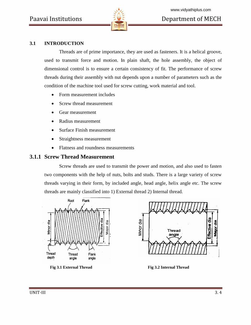
threads are mainly classified into 1) External thread 2) Internal thread.
Fig 3.1 External Thread Fig 3.2 Internal Thread
www.vidyathiplus.com
Paavai Institutions Department of MECH
UNIT-III 3. 5
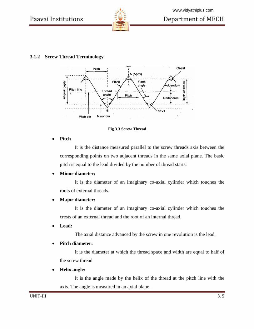
3.1.2 Screw Thread Terminology
Fig 3.3 Screw Thread
Pitch
It is the distance measured parallel to the screw threads axis between the
corresponding points on two adjacent threads in the same axial plane. The basic
pitch is equal to the lead divided by the number of thread starts.
Minor diameter:
It is the diameter of an imaginary co-axial cylinder which touches the
roots of external threads.
Major diameter:
It is the diameter of an imaginary co-axial cylinder which touches the
crests of an external thread and the root of an internal thread.
Lead:
The axial distance advanced by the screw in one revolution is the lead.
Pitch diameter:
It is the diameter at which the thread space and width are equal to half of
the screw thread
Helix angle:
It is the angle made by the helix of the thread at the pitch line with the
axis. The angle is measured in an axial plane.
www.vidyathiplus.com
Paavai Institutions Department of MECH
UNIT-III 3. 6
Flank angle:
It is the angle between the flank and a line normal to the axis passing
through the apex of the thread.
Height of thread:
It is the distance measured radially between the major and minor
diameters respectively
Addendum:
Radial distance between the major and pitch cylinders for external thread.
Radial distance between the minor and pitch cylinder for internal thread.
Dedendum:
It is the radial distance between the pitch and minor cylinders for external
thread. Also radial distance between the major and pitch cylinders for internal
thread.
3.1.3 Error in Thread
The errors in screw thread may arise during the manufacturing or storage of
threads. The errors either may cause in following six main elements in the thread.
1) Major diameter error
2) Minor diameter error
3) Effective diameter error
4) Pitch error
5) Flank angles error
6) Crest and root error
1) Major diameter error
It may cause reduction in the flank contact and interference with the matching
threads.
2) Minor diameter error
It may cause interference, reduction of flank contact.
3) Effective diameter error
www.vidyathiplus.com
Paavai Institutions Department of MECH
UNIT-III 3. 7
If the effective diameter is small the threads will be thin on the external screw and
thick on an internal screw.
4) Pitch errors
If error in pitch, the total length of thread engaged will be either too high or too
small.
The various pitch errors may classified into
1. Progressive error
2. Periodic error
3. Drunken error
4. Irregular error
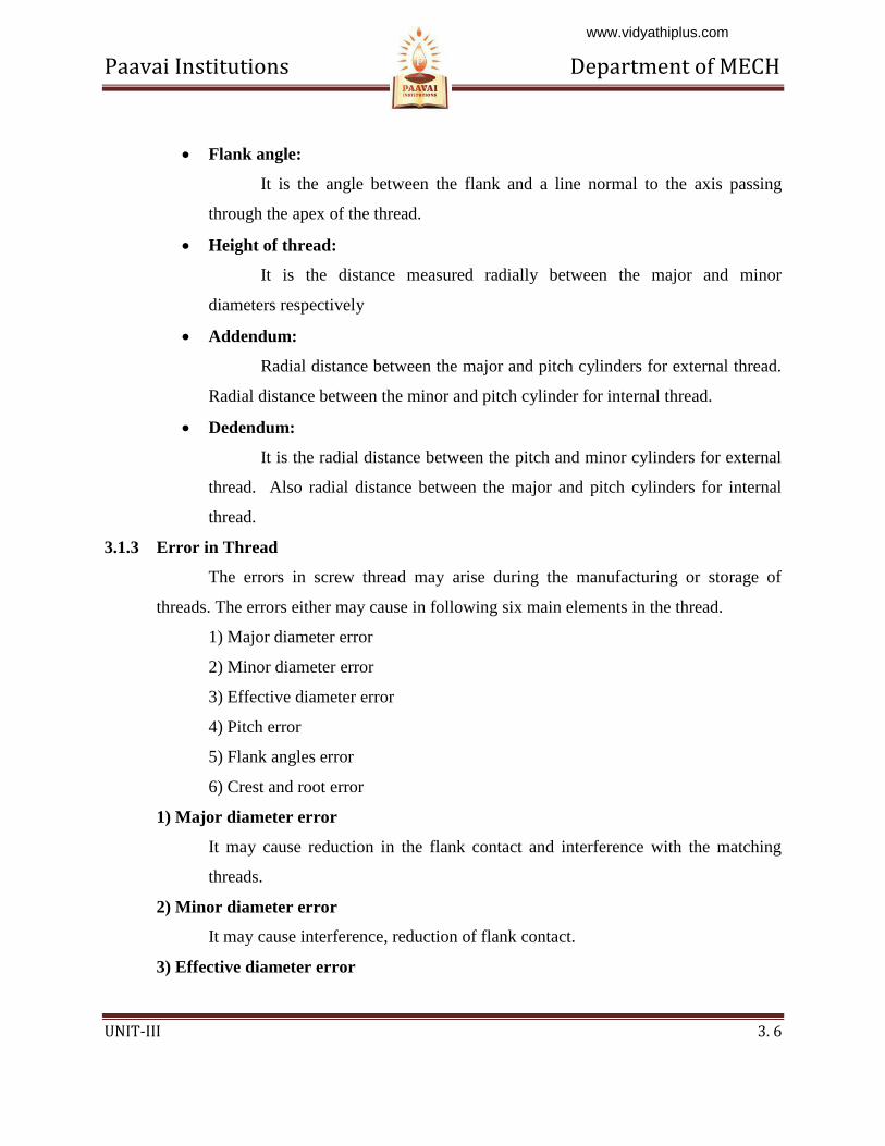
1) Progressive error
The pitch of the thread is uniform but is longer or shorter its nominal value and
this is called progressive.
Causes of progressive error:
1. Incorrect linear and angular velocity ratio.
2. In correct gear train and lead screw.
3. Saddle fault.
4. Variation in length due to hardening.
Fig 3.4 Progressive Error
2) Periodic error
These are repeats itself at regular intervals along the thread
Causes of periodic error:
1. Un uniform tool work velocity ratio.
www.vidyathiplus.com
Paavai Institutions Department of MECH
UNIT-III 3. 8
2. Teeth error in gears.
3. Lead screw error.
4. Eccentric mounting of the gears.
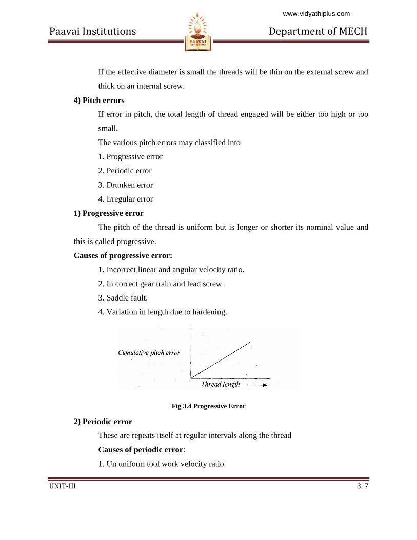
3) Drunken error
Drunken errors are repeated once per turn of the thread in a drunken thread. In
Drunken thread the pitch measured parallel to the thread axis. If the thread is not cut to
the true helix the drunken thread error
will form
Fig 3.5 Drunken Error
4) Irregular errors
It is vary irregular manner along the length of the thread.
Irregular error causes:
1. Machine fault.
2. Non-uniformity in the material.
3. Cutting action is not correct.
4. Machining disturbances.
Effect of pitch errors
Increase the effective diameter of the bolt and decreases the diameter of nut.
The functional diameter of the nut will be less.
Reduce the clearance.
Increase the interference between mating threads.
www.vidyathiplus.com
Paavai Institutions Department of MECH
UNIT-III 3. 9
3.1.4 Measurement of various elements of Thread
To find out the accuracy of a screw thread it will be necessary to measure the following:
1. Major diameter.
2. Minor diameter.
3. Effective or Pitch diameter.
4. Pitch
5. Thread angle and form
1. Measurement of major diameter:
The instruments which are used to find the major diameter are by
Ordinary micrometer
Bench micrometer.
Ordinary micrometer
The ordinary micrometer is quite suitable for measuring the external major
diameter. It is first adjusted for appropriate cylindrical size (S) having the same diameter
(approximately).This process is known as ‘gauge setting’. After taking this reading ‘R the
micrometer is set on the major diameter of the thread, and the new reading is ‘R2.
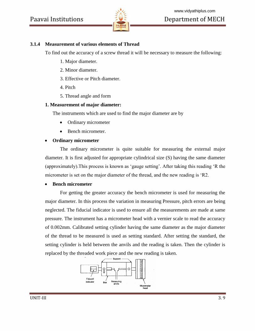
Bench micrometer
For getting the greater accuracy the bench micrometer is used for measuring the
major diameter. In this process the variation in measuring Pressure, pitch errors are being
neglected. The fiducial indicator is used to ensure all the measurements are made at same
pressure. The instrument has a micrometer head with a vernier scale to read the accuracy
of 0.002mm. Calibrated setting cylinder having the same diameter as the major diameter
of the thread to be measured is used as setting standard. After setting the standard, the
setting cylinder is held between the anvils and the reading is taken. Then the cylinder is
replaced by the threaded work piece and the new reading is taken.
www.vidyathiplus.com
Paavai Institutions Department of MECH
UNIT-III 3. 10
Fig 3.6 Bench Micrometer
Measurement of the major diameter of an Internal thread
The Inter thread major diameter is usually measured by thread comparator fitted
with ball-ended styli. First the Instrument is set for a cylindrical reference having the
same diameter of major diameter
of internal thread and the reading is
taken. Then the floating head is
retracted to engage the tips of the styli
at the root of spring under pressure. For that the new reading is taken,
2. Measurement of Minor diameter
The minor diameter is measured by a comparative method by using floating
carriage diameter measuring machine and small V pieces which make contact with the
root of the thread. These V pieces are made in several sizes, having suitable radii at the
edges. V pieces are made of hardened steel. The floating carriage diameter-measuring
machine is a bench micrometer mounted on a carriage.
www.vidyathiplus.com
Paavai Institutions Department of MECH
UNIT-III 3. 11
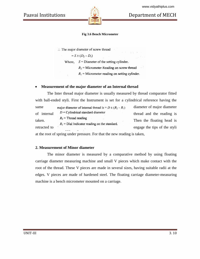
Fig 3.7 Measurement of Minor diameter
Measurement process
The threaded work piece is mounted between the centers of the instrument and the
V pieces are placed on each side of the work piece and then the reading is noted. After
taking this reading the work piece is then replaced by a standard reference cylindrical
setting gauge.
Measurement of Minor diameter of Internal threads
The Minor diameter of Internal threads are measured by
1. Using taper parallels
2. Using Rollers.
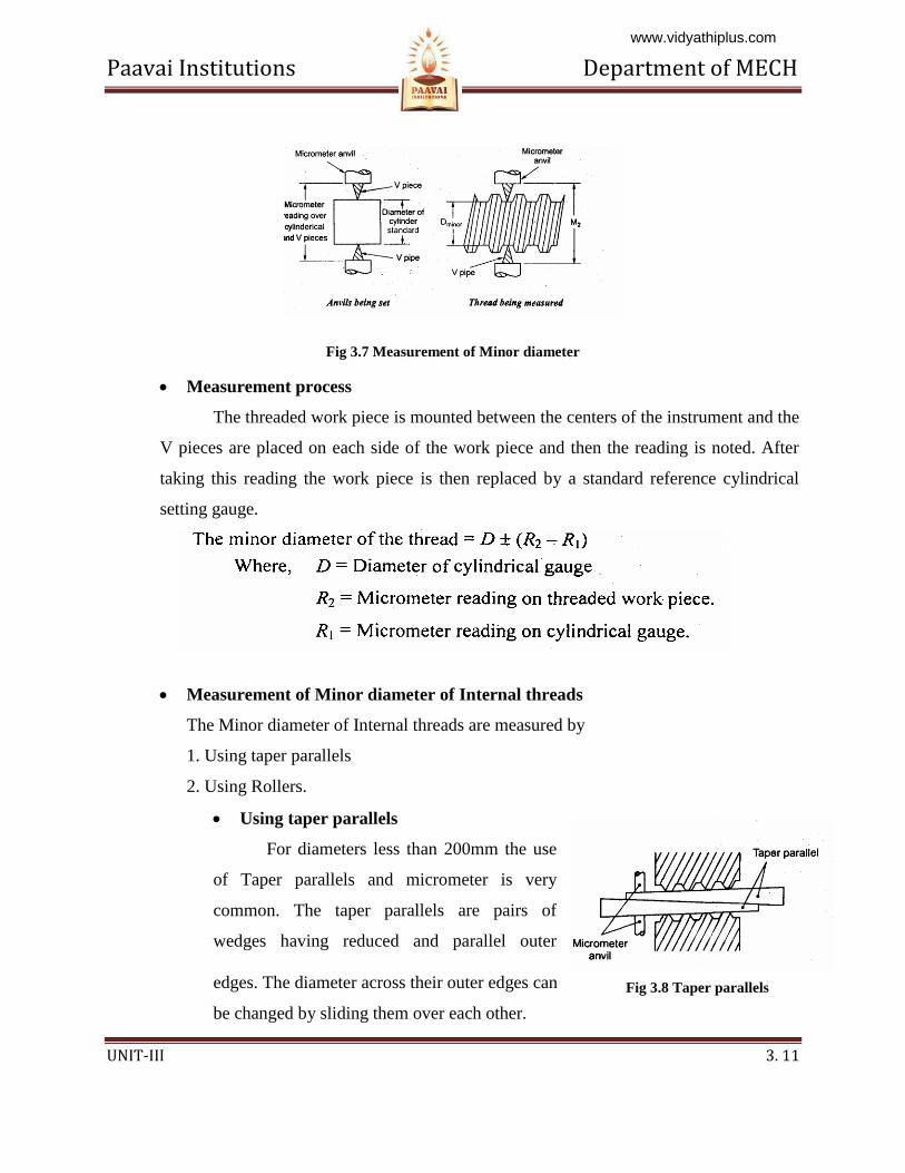
Using taper parallels
For diameters less than 200mm the use
of Taper parallels and micrometer is very
common. The taper parallels are pairs of
wedges having reduced and parallel outer
edges. The diameter across their outer edges can
be changed by sliding them over each other.
Fig 3.8 Taper parallels
www.vidyathiplus.com
Paavai Institutions Department of MECH
UNIT-III 3. 12
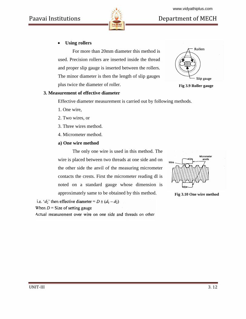
Using rollers
For more than 20mm diameter this method is
used. Precision rollers are inserted inside the thread
and proper slip gauge is inserted between the rollers.
The minor diameter is then the length of slip gauges
plus twice the diameter of roller.
3. Measurement of effective diameter
Effective diameter measurement is carried out by following methods.
1. One wire,
2. Two wires, or
3. Three wires method.
4. Micrometer method.
a) One wire method
The only one wire is used in this method. The
wire is placed between two threads at one side and on
the other side the anvil of the measuring micrometer
contacts the crests. First the micrometer reading dl is
noted on a standard gauge whose dimension is
approximately same to be obtained by this method.
Fig 3.9 Roller gauge
Fig 3.10 One wire method
www.vidyathiplus.com
Paavai Institutions Department of MECH
UNIT-III 3. 13
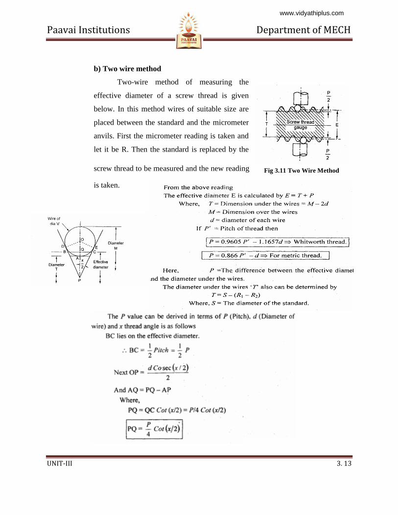
b) Two wire method
Two-wire method of measuring the
effective diameter of a screw thread is given
below. In this method wires of suitable size are
placed between the standard and the micrometer
anvils. First the micrometer reading is taken and
let it be R. Then the standard is replaced by the
screw thread to be measured and the new reading
is taken.
Fig 3.11 Two Wire Method
www.vidyathiplus.com
Paavai Institutions Department of MECH
UNIT-III 3. 14
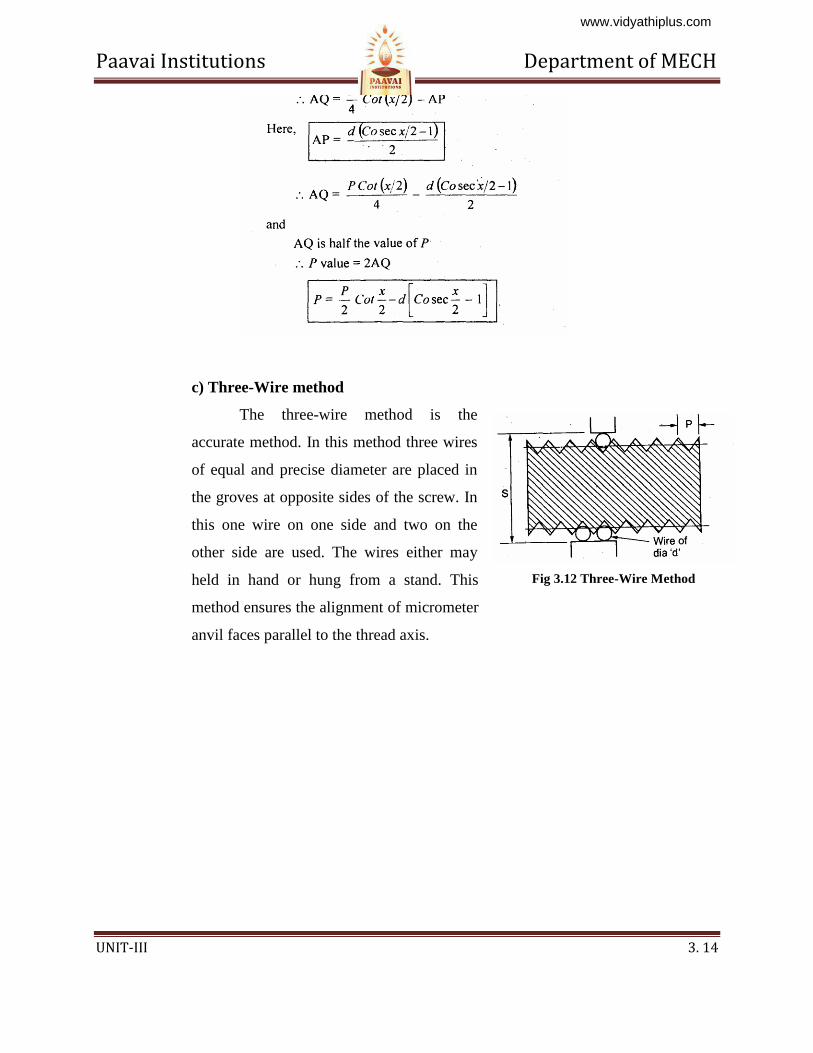
c) Three-Wire method
The three-wire method is the
accurate method. In this method three wires
of equal and precise diameter are placed in
the groves at opposite sides of the screw. In
this one wire on one side and two on the
other side are used. The wires either may
held in hand or hung from a stand. This
method ensures the alignment of micrometer
anvil faces parallel to the thread axis.
Fig 3.12 Three-Wire Method
www.vidyathiplus.com
Paavai Institutions Department of MECH
UNIT-III 3. 15
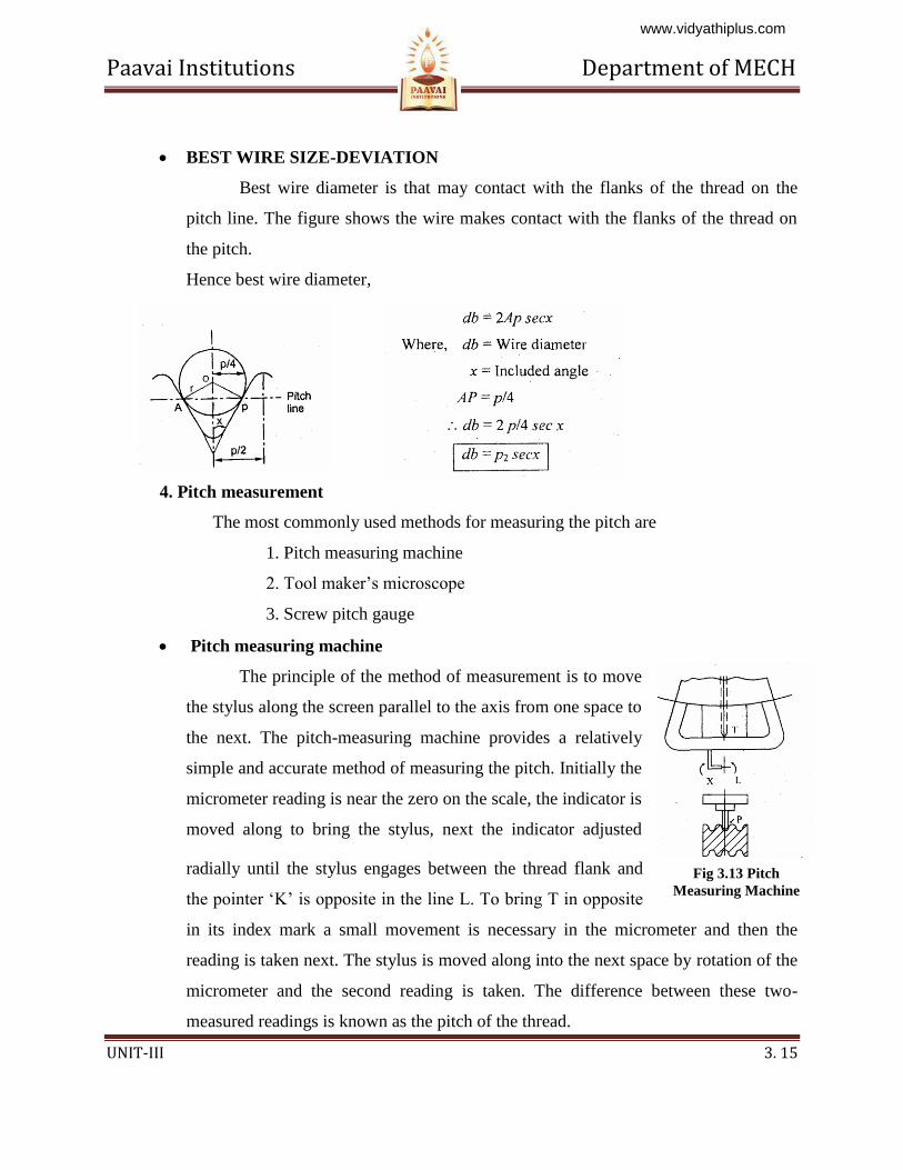
BEST WIRE SIZE-DEVIATION
Best wire diameter is that may contact with the flanks of the thread on the
pitch line. The figure shows the wire makes contact with the flanks of the thread on
the pitch.
Hence best wire diameter,
4. Pitch measurement
The most commonly used methods for measuring the pitch are
1. Pitch measuring machine
2. Tool maker’s microscope
3. Screw pitch gauge
Pitch measuring machine
The principle of the method of measurement is to move
the stylus along the screen parallel to the axis from one space to
the next. The pitch-measuring machine provides a relatively
simple and accurate method of measuring the pitch. Initially the
micrometer reading is near the zero on the scale, the indicator is
moved along to bring the stylus, next the indicator adjusted
radially until the stylus engages between the thread flank and
the pointer ‘K’ is opposite in the line L. To bring T in opposite
in its index mark a small movement is necessary in the micrometer and then the
reading is taken next. The stylus is moved along into the next space by rotation of the
micrometer and the second reading is taken. The difference between these two-
measured readings is known as the pitch of the thread.
Fig 3.13 Pitch
Measuring Machine
www.vidyathiplus.com
Paavai Institutions Department of MECH
UNIT-III 3. 16
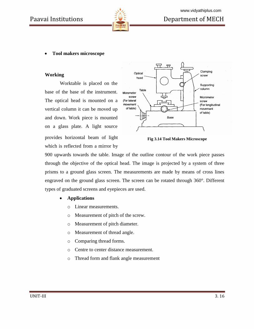
Tool makers microscope
Working
Worktable is placed on the
base of the base of the instrument.
The optical head is mounted on a
vertical column it can be moved up
and down. Work piece is mounted
on a glass plate. A light source
provides horizontal beam of light
which is reflected from a mirror by
900 upwards towards the table. Image of the outline contour of the work piece passes
through the objective of the optical head. The image is projected by a system of three
prisms to a ground glass screen. The measurements are made by means of cross lines
engraved on the ground glass screen. The screen can be rotated through 360°. Different
types of graduated screens and eyepieces are used.
Applications
o Linear measurements.
o Measurement of pitch of the screw.
o Measurement of pitch diameter.
o Measurement of thread angle.
o Comparing thread forms.
o Centre to center distance measurement.
o Thread form and flank angle measurement
Fig 3.14 Tool Makers Microscope
www.vidyathiplus.com
Paavai Institutions Department of MECH
UNIT-III 3. 17
Thread form and flank angle measurement
The optical projections are used to check the thread form and angles in the
thread. The projectors equipped with work holding fixtures, lamp, and lenses. The
light rays from the lens are directed into the cabinet and prisons and mirrors. The
enlarged image of thread is drawn. The ideal and actual forms are compared for
the measurement.
3.2 GEAR MEASUREMENT
3.2.1 Introduction
Gear is a mechanical drive which transmits power through toothed wheel. In this
gear drive, the driving wheel is in direct contact with driven wheel. The accuracy of
gearing is the very important factor when gears are manufactured. The transmission
efficiency is almost 99 in gears. So it is very important to test and measure the gears
precisely. For proper inspection of gear, it is very important to concentrate on the raw
materials, which are used to manufacture the gears, also very important to check the
machining the blanks, heat treatment and the finishing of teeth. The gear blanks should be
tested for dimensional accuracy and tooth thickness for the forms of gears.
The most commonly used forms of gear teeth are
1. Involute
2. Cycloidal
The involute gears also called as straight tooth or spur gears. The cycloidal
gears are used in heavy and impact loads. The involute rack has straight teeth. The
involute pressure angle is either 20° or 14.5°.
3.2.2 Types of gears
1. Spur gear
Cylindrical gear whose tooth traces is straight line. These are used for
transmitting power between parallel shafts.
2. Spiral gear
The tooth of the gear traces curved lines.
www.vidyathiplus.com
Paavai Institutions Department of MECH
UNIT-III 3. 18
3. Helical gears
These gears used to transmit the power between parallel shafts as well as
nonparallel and non-intersecting shafts. It is a cylindrical gear whose tooth traces is
straight line.
4. Bevel gears:
The tooth traces are straight-line generators of cone. The teeth are cut on the
conical surface. It is used to connect the shafts at right angles.
5. Worm and Worm wheel:
It is used to connect the shafts whose axes are non-parallel and non-intersecting.
6. Rack and Pinion:
Rack gears are straight spur gears with infinite radius.
3.2.3 Gear terminology
1. Tooth profile
It is the shape of any side of gear tooth in its cross section.
2. Base circle
It is the circle of gear from which the involute profile is derived. Base circle
diameter Pitch circle diameter x Cosine of pressure angle of gear
3. Pitch circle diameter (PCD)
The diameter of a circle which will produce the same motion as the toothed gear
wheel.
4. Pitch circle
It is the imaginary circle of gear that rolls without slipping over the circle of its
matiug gear.
5. Addendum circle
The circle coincides with the crests (or) tops of teeth.
6. Dedendum circle (or) Root circle
www.vidyathiplus.com

Paavai Institutions Department of MECH
UNIT-III 3. 19
This circle coincides with the roots (or) bottom on teeth.
7. Pressure angle (a)
It is the angle making by the line of action with the common tangent to the pitch
circles of mating gears.
8. Module(m)
It is the ratio of pitch circle diameter to the total number of teeth. Where,
d = Pitch circle diameter. n = Number f teeth.
9. Circular pitch
It is the distance along the pitch circle between corresponding points of adjacent
teeth.
10. Addendum
Radial distance between tip circle and pitch circle. Addendum value = 1 module.
11 Dedendum
Radial distance between itch circle and root circle,
Dedendum value = 1 .25module.
12. Clearance (C)
Amount of distance made by the tip of one gear with the root of mating gear.
Clearance = Difference between Dedendum and addendum values.
13. Blank diameter:
The diameter of the blank from which gear is out. Blank diameter = PCD + 2m
14. Face:
Part of the tooth in the axial plane lying between tip circle and pitch circle.
15. Flank:
Part of the tooth lying between pitch circle and root circle.
16. Top land:
Top surface of a tooth.
17. Lead angle
The angle between the tangent to the helix and plane perpendicular to the axis of
cylinder.
www.vidyathiplus.com
Paavai Institutions Department of MECH
UNIT-III 3. 20
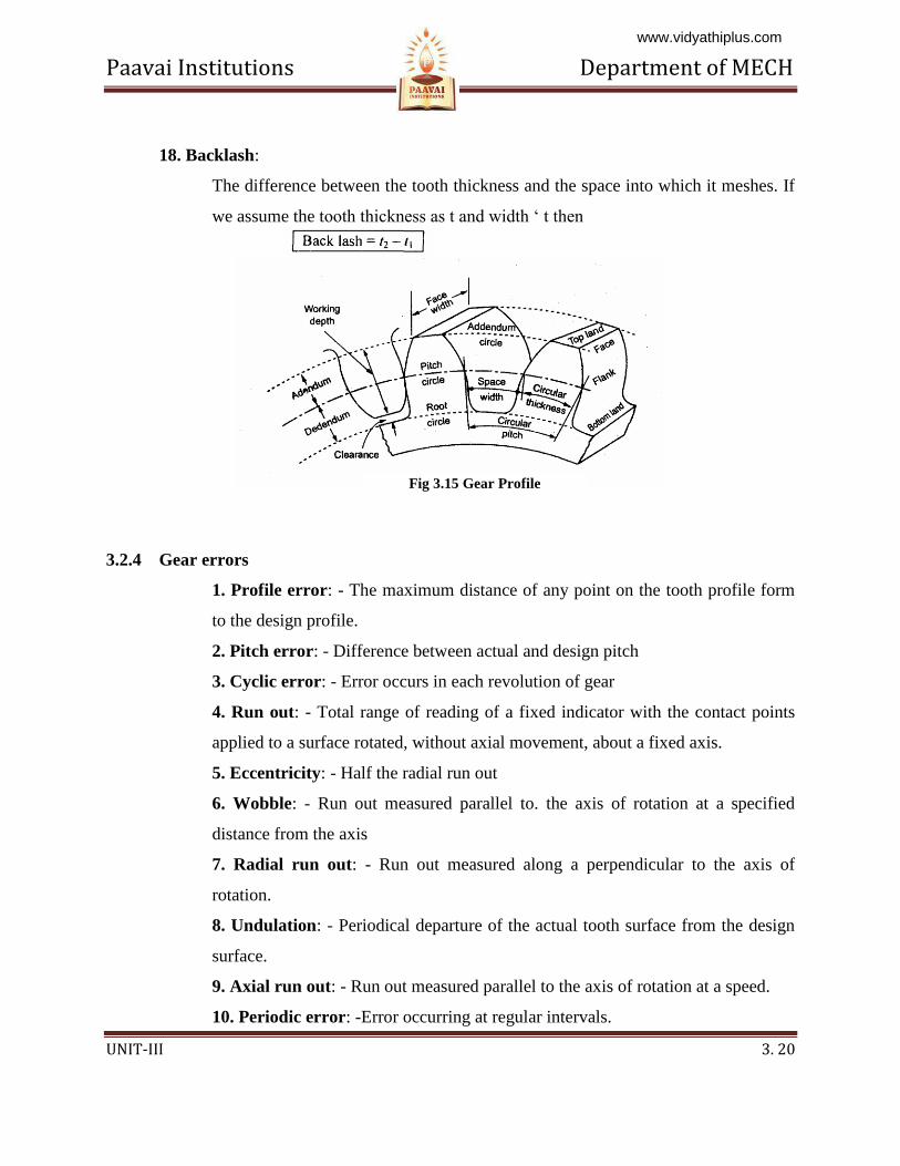
18. Backlash:
The difference between the tooth thickness and the space into which it meshes. If
we assume the tooth thickness as t and width ‘ t then
3.2.4 Gear errors
1. Profile error: - The maximum distance of any point on the tooth profile form
to the design profile.
2. Pitch error: - Difference between actual and design pitch
3. Cyclic error: - Error occurs in each revolution of gear
4. Run out: - Total range of reading of a fixed indicator with the contact points
applied to a surface rotated, without axial movement, about a fixed axis.
5. Eccentricity: - Half the radial run out
6. Wobble: - Run out measured parallel to. the axis of rotation at a specified
distance from the axis
7. Radial run out: - Run out measured along a perpendicular to the axis of
rotation.
8. Undulation: - Periodical departure of the actual tooth surface from the design
surface.
9. Axial run out: - Run out measured parallel to the axis of rotation at a speed.
10. Periodic error: -Error occurring at regular intervals.
Fig 3.15 Gear Profile
www.vidyathiplus.com
Paavai Institutions Department of MECH
UNIT-III 3. 21
3.2.5 Gear Measurement
The Inspection of the gears consists of determine the following elements in which
manufacturing error may be present.
1. Runout.
2. Pitch
3. Profile
4. Lead
5. Back lash
6. Tooth thickness
7. Concentricity
8. Alignment
1. Runout:
It means eccentricity in the pitch circle. It will give periodic vibration during each
revolution of the gear. This will give the tooth failure in gears. The run out is measured
by means of eccentricity testers. In the testing the gears are placed in the mandrel and the
dial indicator of the tester possesses special tip depending upon the module of the gear
and the tips inserted between the tooth spaces and the gears are rotated tooth by tooth and
the variation is noted from the dial indicator.
2. Pitch measurement:
There are two ways for measuring the pitch.
1. Point to point measurement (i.e. One tooth point to next toot point)
2. Direct angular measurement
1. Tooth to Tooth measurement
www.vidyathiplus.com
Paavai Institutions Department of MECH
UNIT-III 3. 22
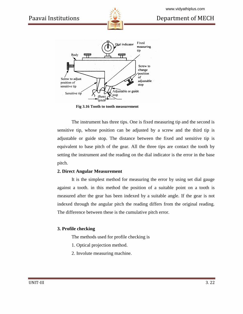
The instrument has three tips. One is fixed measuring tip and the second is
sensitive tip, whose position can be adjusted by a screw and the third tip is
adjustable or guide stop. The distance between the fixed and sensitive tip is
equivalent to base pitch of the gear. All the three tips are contact the tooth by
setting the instrument and the reading on the dial indicator is the error in the base
pitch.
2. Direct Angular Measurement
It is the simplest method for measuring the error by using set dial gauge
against a tooth. in this method the position of a suitable point on a tooth is
measured after the gear has been indexed by a suitable angle. If the gear is not
indexed through the angular pitch the reading differs from the original reading.
The difference between these is the cumulative pitch error.
3. Profile checking
The methods used for profile checking is
1. Optical projection method.
2. Involute measuring machine.
Fig 3.16 Tooth to tooth measurement
www.vidyathiplus.com
Paavai Institutions Department of MECH
UNIT-III 3. 23
1. Optical projection method:
The profile of the gear projected on the screen by optical lens and
then projected value is compared with master profile.
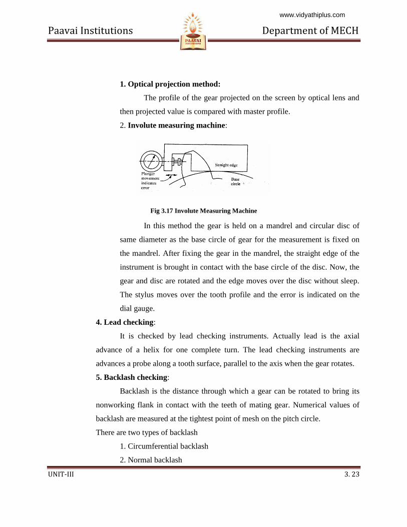
2. Involute measuring machine:
Fig 3.17 Involute Measuring Machine
In this method the gear is held on a mandrel and circular disc of
same diameter as the base circle of gear for the measurement is fixed on
the mandrel. After fixing the gear in the mandrel, the straight edge of the
instrument is brought in contact with the base circle of the disc. Now, the
gear and disc are rotated and the edge moves over the disc without sleep.
The stylus moves over the tooth profile and the error is indicated on the
dial gauge.
4. Lead checking:
It is checked by lead checking instruments. Actually lead is the axial
advance of a helix for one complete turn. The lead checking instruments are
advances a probe along a tooth surface, parallel to the axis when the gear rotates.
5. Backlash checking:
Backlash is the distance through which a gear can be rotated to bring its
nonworking flank in contact with the teeth of mating gear. Numerical values of
backlash are measured at the tightest point of mesh on the pitch circle.
There are two types of backlash
1. Circumferential backlash
2. Normal backlash
www.vidyathiplus.com
Paavai Institutions Department of MECH
UNIT-III 3. 24
The determination of backlash is, first one of the two gears of the pair is
locked, while other is rotated forward and backward and by the comparator the
maximum displacement is measured. The stylus of comparator is locked near the
reference cylinder and a tangent to this is called circular backlash.
6. Tooth thickness measurement:
Tooth thickness is generally measured at pitch circle and also in most
cases the chordal thickness measurement is carried out i.e. the chord joining the
intersection of the tooth profile with the pitch circle.
The methods which are used for measuring the gear tooth thickness is
a) Gear tooth vernier caliper method (Chordal thickness method)
b) Base tangent method.
c) Constant chord method.
d) Measurement over pins or balls.
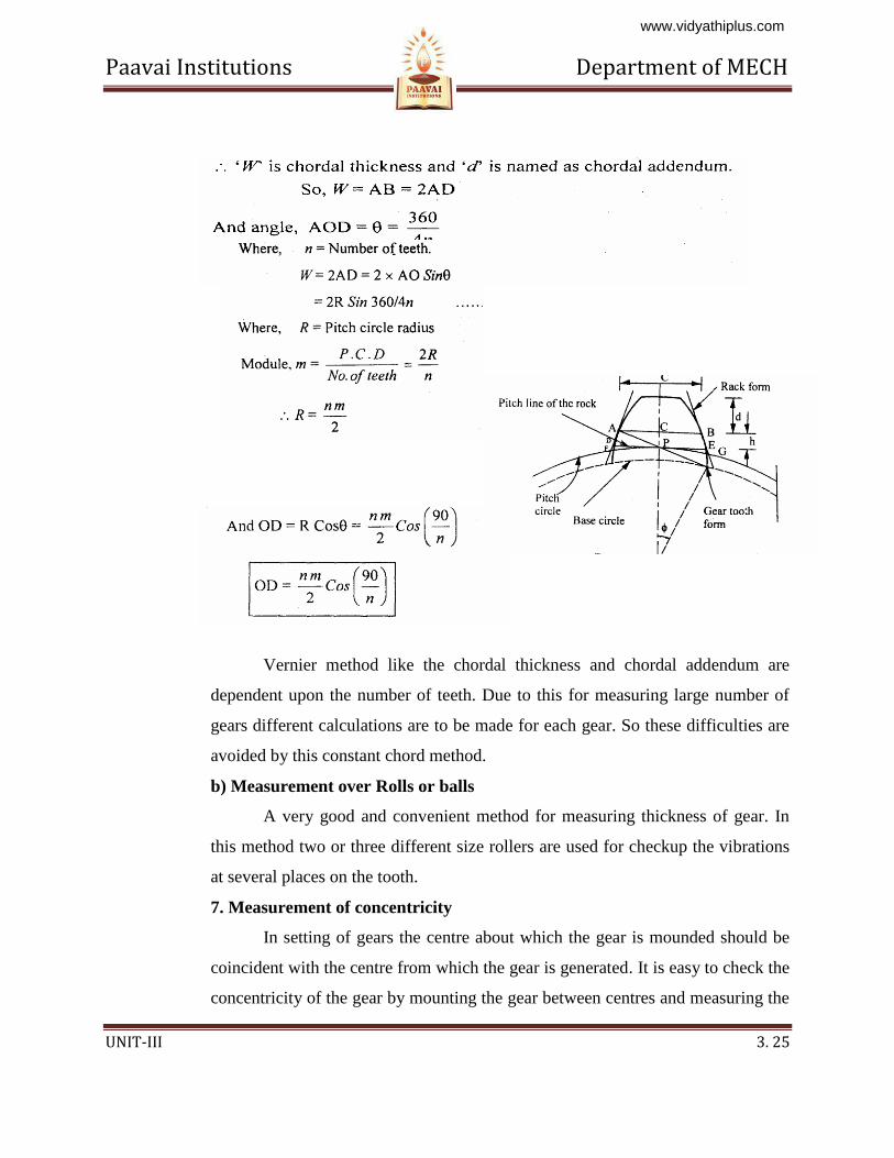
a) Gear tooth vernier method
In gear tooth vernier method the thickness is measured at the pitch line.
Gear tooth thickness varies from the tip of the base circle of the tooth, and the
instrument is capable of measuring the thickness at a specified position on the
tooth. The tooth vernier caliper consists of vernier scale and two perpendicular
arms. In the two perpendicular arms one arm is used to measure the thickness and
other arm is used to measure the depth. Horizontal vernier scale reading gives
chordal thickness (W) and vertical vernier scale gives the chordal addendum.
Finally the two values compared.
The theoretical values of W and d can be found out by considering one
tooth in the gear and it can be verified. In fig noted that w is a chord ADB and
tooth thickness is specified by AEB. The distance d is noted and adjusted on
instrument and it is slightly greater than addendum CE.
www.vidyathiplus.com
Paavai Institutions Department of MECH
UNIT-III 3. 25
Vernier method like the chordal thickness and chordal addendum are
dependent upon the number of teeth. Due to this for measuring large number of
gears different calculations are to be made for each gear. So these difficulties are
avoided by this constant chord method.
b) Measurement over Rolls or balls
A very good and convenient method for measuring thickness of gear. In
this method two or three different size rollers are used for checkup the vibrations
at several places on the tooth.
7. Measurement of concentricity
In setting of gears the centre about which the gear is mounded should be
coincident with the centre from which the gear is generated. It is easy to check the
concentricity of the gear by mounting the gear between centres and measuring the
www.vidyathiplus.com
Paavai Institutions Department of MECH
UNIT-III 3. 26
variation in height of a roller placed between the successive teeth. Finally the
variation in reading will be a function of the eccentricity present.
8. Alignment checking
It is done by placing a parallel bar between the gear teeth and the gear
being mounted between centres. Finally the readings are taken at the two ends of
the bar and difference in reading is the misalignment.
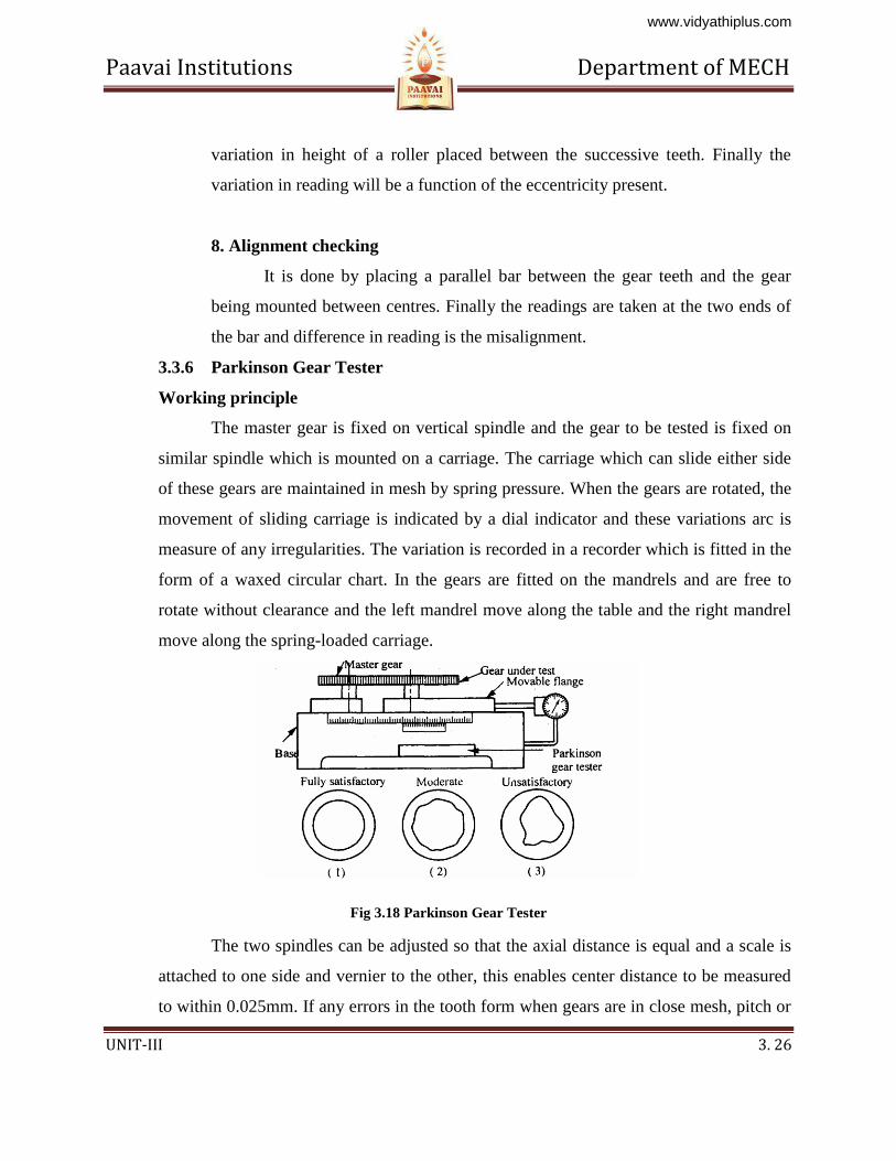
3.3.6 Parkinson Gear Tester
Working principle
The master gear is fixed on vertical spindle and the gear to be tested is fixed on
similar spindle which is mounted on a carriage. The carriage which can slide either side
of these gears are maintained in mesh by spring pressure. When the gears are rotated, the
movement of sliding carriage is indicated by a dial indicator and these variations arc is
measure of any irregularities. The variation is recorded in a recorder which is fitted in the
form of a waxed circular chart. In the gears are fitted on the mandrels and are free to
rotate without clearance and the left mandrel move along the table and the right mandrel
move along the spring-loaded carriage.
Fig 3.18 Parkinson Gear Tester
The two spindles can be adjusted so that the axial distance is equal and a scale is
attached to one side and vernier to the other, this enables center distance to be measured
to within 0.025mm. If any errors in the tooth form when gears are in close mesh, pitch or
www.vidyathiplus.com
Paavai Institutions Department of MECH
UNIT-III 3. 27
concentricity of pitch line will cause a variation in center distance from this movement of
carriage as indicated to the dial gauge will show the errors in the gear test. The recorder
also fitted in the form of circular or rectangular chart and the errors are recorded.
Limitations of Parkinson gear tester:
1. Accuracy±0.001mm
2. Maximum gear diameter is 300mm
3. Errors are not clearly identified:
4. Measurement dependent upon the master gear.
5. Low friction in the movement of the floating carriage.
3.4 RADIUS MEASUREMENT
In radius measurement we are going see about two methods namely.
1 Radius of circle and
2. Radius of concave surface
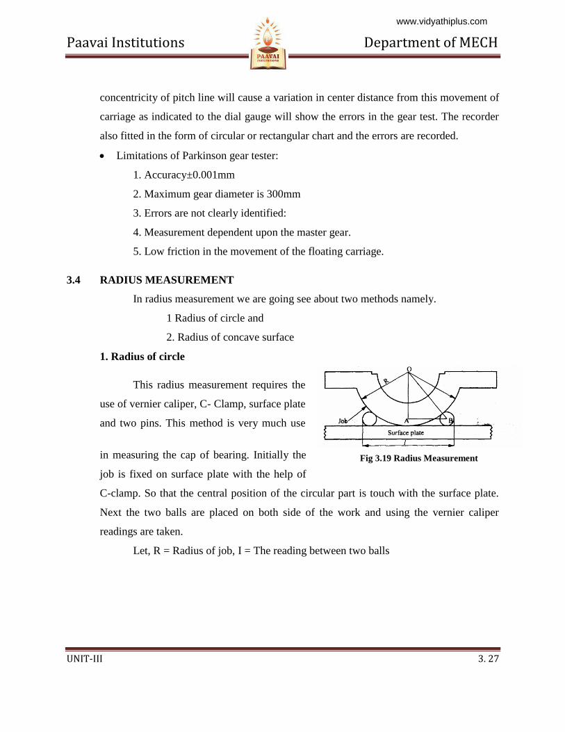
1. Radius of circle
This radius measurement requires the
use of vernier caliper, C- Clamp, surface plate
and two pins. This method is very much use
in measuring the cap of bearing. Initially the
job is fixed on surface plate with the help of
C-clamp. So that the central position of the circular part is touch with the surface plate.
Next the two balls are placed on both side of the work and using the vernier caliper
readings are taken.
Let, R = Radius of job, I = The reading between two balls
Fig 3.19 Radius Measurement
www.vidyathiplus.com
Paavai Institutions Department of MECH
UNIT-III 3. 28
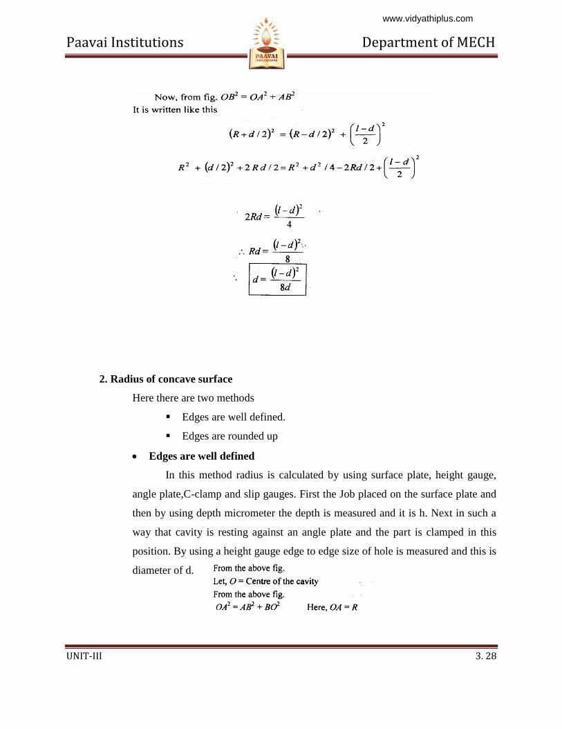
2. Radius of concave surface
Here there are two methods
Edges are well defined.
Edges are rounded up
Edges are well defined
In this method radius is calculated by using surface plate, height gauge,
angle plate,C-clamp and slip gauges. First the Job placed on the surface plate and
then by using depth micrometer the depth is measured and it is h. Next in such a
way that cavity is resting against an angle plate and the part is clamped in this
position. By using a height gauge edge to edge size of hole is measured and this is
diameter of d.
www.vidyathiplus.com

Paavai Institutions Department of MECH
UNIT-III 3. 29
When cavities are rounded up the radius is measured by depth micrometer
and slip gauges. First the width of the micrometer is measured by slip gauges and
it is let ‘ d’. Then it is placed in the cavity and measuring tip is lowered down to
touches the base. From this condition the reading is noted and it be h and the
radius is measured by using the formula
2) Edges are rounded up
When cavities are rounded up the radius is measured by depth micrometer
and slip gauges. First the width of the micrometer is measured
by slip gauges and it is let ‘d’. Then it is
placed in the cavity and measuring tip
is lowered down to touches the base.
From this condition the reading is noted
and it be h and the radius is measured
by using the formula
3.5 SURFACE FINISH MEASUREMENT
Fig 3.21 Edges round up
Fig 3.20 Radius of Concave
surface
www.vidyathiplus.com
Paavai Institutions Department of MECH
UNIT-III 3. 30
3.5.1 Introduction
When we are producing components by various methods of manufacturing
process it is not possible to produce perfectly smooth surface and some irregularities are
formed. These irregularities are causes some serious difficulties in using the components.
So it is very important to correct the surfaces before use. The factors which are affecting
surface roughness are
1. Work piece material
2. Vibrations
3. Machining type
4. Tool and fixtures
The geometrical irregularities can be classified as
1. First order
2. Second order
3 Third order
4. Fourth order
1. First order irregularities
These are caused by lack of straightness of guide ways on which tool must
move.
2. Second order irregularities
These are caused by vibrations
3. Third order irregularities
These are caused by machining.
4. Fourth order irregularities
These are caused by improper handling machines and equipments.
www.vidyathiplus.com
Paavai Institutions Department of MECH
UNIT-III 3. 31
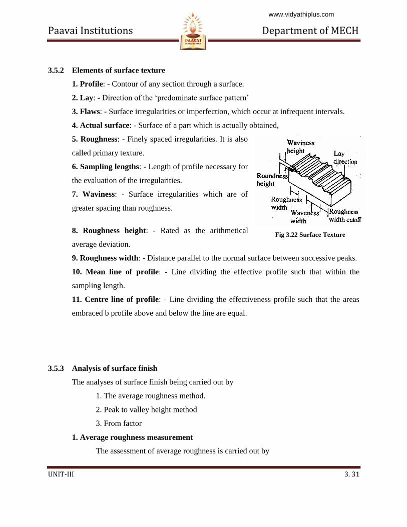
3.5.2 Elements of surface texture
1. Profile: - Contour of any section through a surface.
2. Lay: - Direction of the ‘predominate surface pattern’
3. Flaws: - Surface irregularities or imperfection, which occur at infrequent intervals.
4. Actual surface: - Surface of a part which is actually obtained,
5. Roughness: - Finely spaced irregularities. It is also
called primary texture.
6. Sampling lengths: - Length of profile necessary for
the evaluation of the irregularities.
7. Waviness: - Surface irregularities which are of
greater spacing than roughness.
8. Roughness height: - Rated as the arithmetical
average deviation.
9. Roughness width: - Distance parallel to the normal surface between successive peaks.
10. Mean line of profile: - Line dividing the effective profile such that within the
sampling length.
11. Centre line of profile: - Line dividing the effectiveness profile such that the areas
embraced b profile above and below the line are equal.
3.5.3 Analysis of surface finish
The analyses of surface finish being carried out by
1. The average roughness method.
2. Peak to valley height method
3. From factor
1. Average roughness measurement
The assessment of average roughness is carried out by
Fig 3.22 Surface Texture
www.vidyathiplus.com
Paavai Institutions Department of MECH
UNIT-III 3. 32
a Centre line average (CLA).
b Root mean square (RMS)
c Ten point method
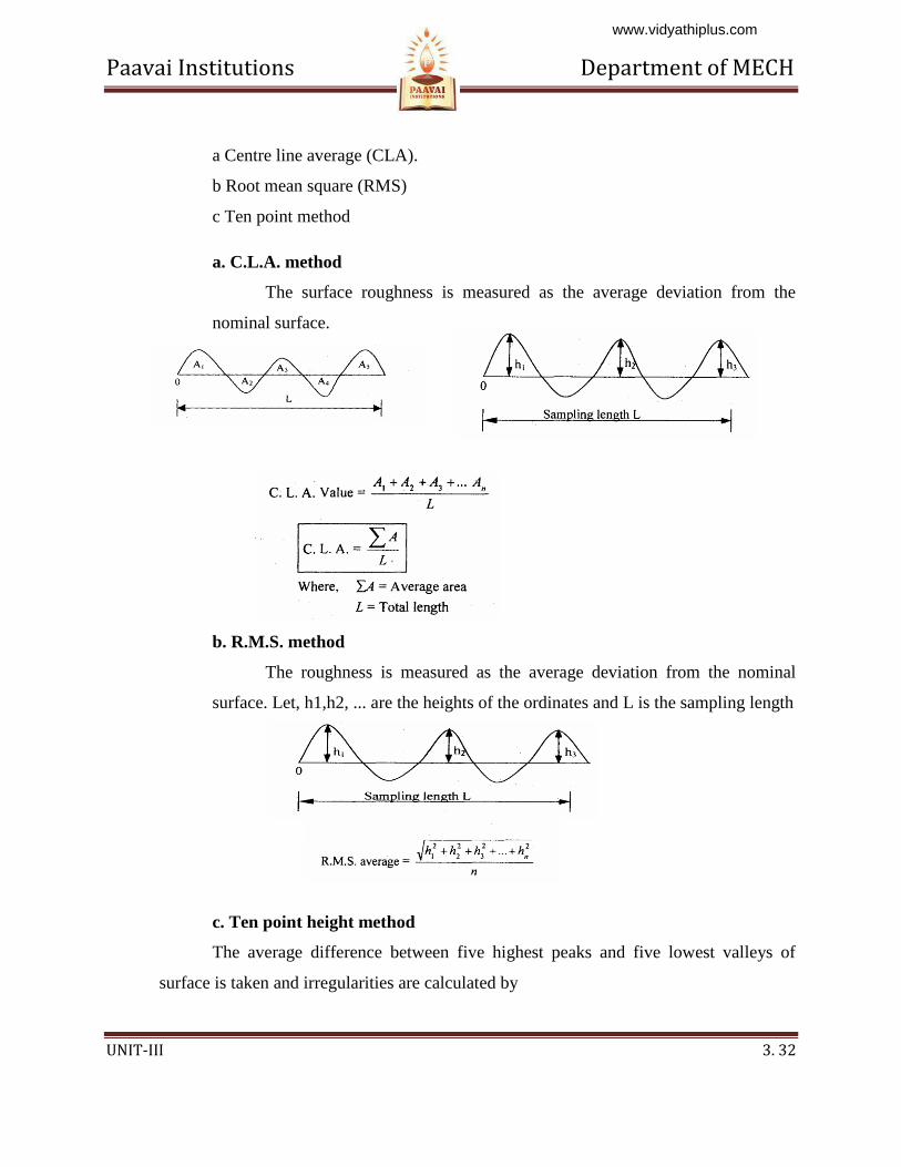
a. C.L.A. method
The surface roughness is measured as the average deviation from the
nominal surface.
b. R.M.S. method
The roughness is measured as the average deviation from the nominal
surface. Let, h1,h2, ... are the heights of the ordinates and L is the sampling length
c. Ten point height method
The average difference between five highest peaks and five lowest valleys of
surface is taken and irregularities are calculated by
www.vidyathiplus.com
Paavai Institutions Department of MECH
UNIT-III 3. 33
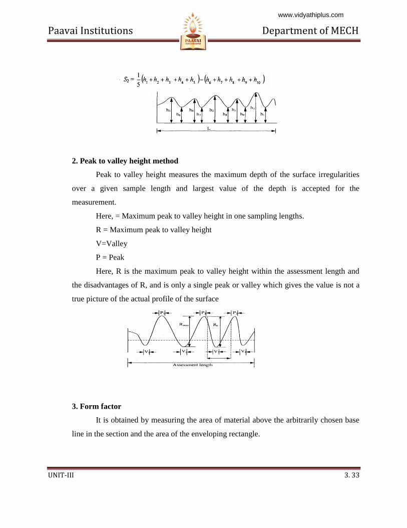
2. Peak to valley height method
Peak to valley height measures the maximum depth of the surface irregularities
over a given sample length and largest value of the depth is accepted for the
measurement.
Here, = Maximum peak to valley height in one sampling lengths.
R = Maximum peak to valley height
V=Valley
P = Peak
Here, R is the maximum peak to valley height within the assessment length and
the disadvantages of R, and is only a single peak or valley which gives the value is not a
true picture of the actual profile of the surface
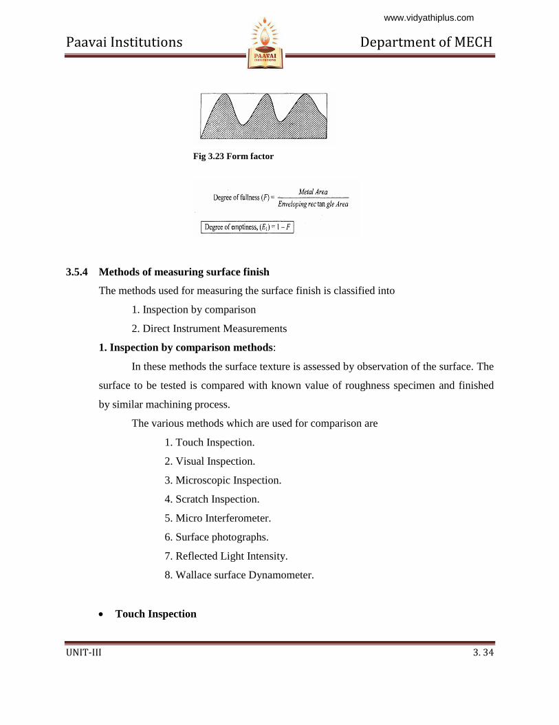
3. Form factor
It is obtained by measuring the area of material above the arbitrarily chosen base
line in the section and the area of the enveloping rectangle.
www.vidyathiplus.com
Paavai Institutions Department of MECH
UNIT-III 3. 34
3.5.4 Methods of measuring surface finish
The methods used for measuring the surface finish is classified into
1. Inspection by comparison
2. Direct Instrument Measurements
1. Inspection by comparison methods:
In these methods the surface texture is assessed by observation of the surface. The
surface to be tested is compared with known value of roughness specimen and finished
by similar machining process.
The various methods which are used for comparison are
1. Touch Inspection.
2. Visual Inspection.
3. Microscopic Inspection.
4. Scratch Inspection.
5. Micro Interferometer.
6. Surface photographs.
7. Reflected Light Intensity.
8. Wallace surface Dynamometer.
Touch Inspection
Fig 3.23 Form factor
www.vidyathiplus.com
Paavai Institutions Department of MECH
UNIT-III 3. 35
It is used when surface roughness is very high and in this method the fingertip is
moved along the surface at a speed of 25mm/second and the irregularities as up to
0.0125mm can be detected.
Visual Inspection
In this method the surface is inspected by naked eye and this measurement is
limited to rough surfaces.
Microscopic Inspection
In this method finished surface is placed under the microscopic and compared
with the surface under inspection. The light beam also used to check the finished surface
by projecting the light about 60° to the work.
Scratch Inspection:
The materials like lead, plastics rubbed on surface are inspected by this method.
The impression of this scratches on the surface produced is then visualized.
Micro-Interferometer
Optical flat is placed on the surface to be inspected and illuminated by a
monochromatic source of light.
Surface Photographs
Magnified photographs of the surface are taken with different types of
illumination. The defects like irregularities are appear as dark spots and flat portion of the
surface appears as bright.
Reflected light Intensity
A beam of light is projected on the surface to be inspected and the light intensity
variation on the surface is measured by a photocell and this measured value is calibrated
Wallace surface Dynamometer:
It consists of a pendulum in which the testing shoes are clamped to a bearing
surface and a pre determined spring pressure can be applied and then, The pendulum is
lifted to its initial starting position and allowed to swing over the surface to be tested.
www.vidyathiplus.com
Paavai Institutions Department of MECH
UNIT-III 3. 36
2. Direct instrument measurements
Direct methods enable to determine a numerical value of the surface finish of any
surface. These methods are quantitative analysis methods and the output is used to
operate recording or indicating instrument. Direct Instruments are operated by electrical
principles. These instruments are classified into two types according to the operating
principle. In this is operated by carrier-modulating principle and the other is operated by
voltage-generating principle, and in the both types the output is amplified.
Some of the direct measurement instruments are
1. Stylus probe instruments.
2. Tomlinson surface meter.
3. Profilometer.
4. Taylor-Hobson Talysurf
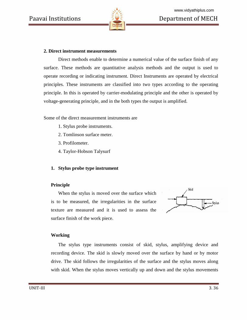
1. Stylus probe type instrument
Principle
When the stylus is moved over the surface which
is to be measured, the irregularities in the surface
texture are measured and it is used to assess the
surface finish of the work piece.
Working
The stylus type instruments consist of skid, stylus, amplifying device and
recording device. The skid is slowly moved over the surface by hand or by motor
drive. The skid follows the irregularities of the surface and the stylus moves along
with skid. When the stylus moves vertically up and down and the stylus movements
www.vidyathiplus.com
Paavai Institutions Department of MECH
UNIT-III 3. 37
are magnified, amplified and recorded to produce a trace. Then it is analyzed by
automatic device.
Advantage
Any desired roughness parameter can be recorded.
Disadvantages
1. Fragile material cannot be measured.
2. High Initial cost.
3. Skilled operators are needed to operate.
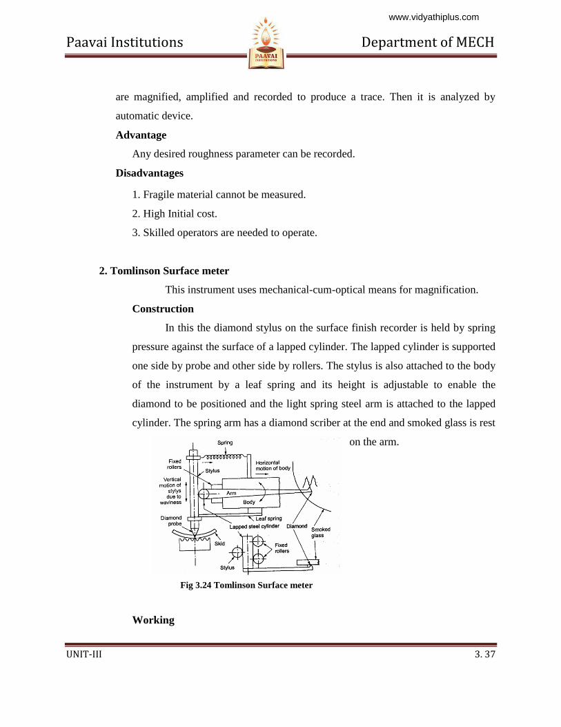
2. Tomlinson Surface meter
This instrument uses mechanical-cum-optical means for magnification.
Construction
In this the diamond stylus on the surface finish recorder is held by spring
pressure against the surface of a lapped cylinder. The lapped cylinder is supported
one side by probe and other side by rollers. The stylus is also attached to the body
of the instrument by a leaf spring and its height is adjustable to enable the
diamond to be positioned and the light spring steel arm is attached to the lapped
cylinder. The spring arm has a diamond scriber at the end and smoked glass is rest
on the arm.
Working
Fig 3.24 Tomlinson Surface meter
www.vidyathiplus.com
Paavai Institutions Department of MECH
UNIT-III 3. 38
When measuring surface finish the body of the instrument is moved across
the surface by a screw rotation. The vertical movement of the probe caused by the
surface irregularities makes the horizontal lapped cylinder to roll. This rolling of
lapped cylinder causes the movement of the arm. So this movement is induces the
diamond scriber on smoked glass. Finally the movement of scriber together with
horizontal movement produces a trace on the smoked glass plate and this trace is
magnified by an optical projector.
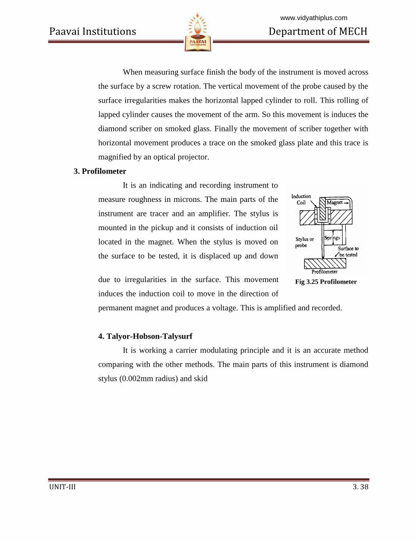
3. Profilometer
It is an indicating and recording instrument to
measure roughness in microns. The main parts of the
instrument are tracer and an amplifier. The stylus is
mounted in the pickup and it consists of induction oil
located in the magnet. When the stylus is moved on
the surface to be tested, it is displaced up and down
due to irregularities in the surface. This movement
induces the induction coil to move in the direction of
permanent magnet and produces a voltage. This is amplified and recorded.
4. Talyor-Hobson-Talysurf
It is working a carrier modulating principle and it is an accurate method
comparing with the other methods. The main parts of this instrument is diamond
stylus (0.002mm radius) and skid
Fig 3.25 Profilometer
www.vidyathiplus.com
Paavai Institutions Department of MECH
UNIT-III 3. 39
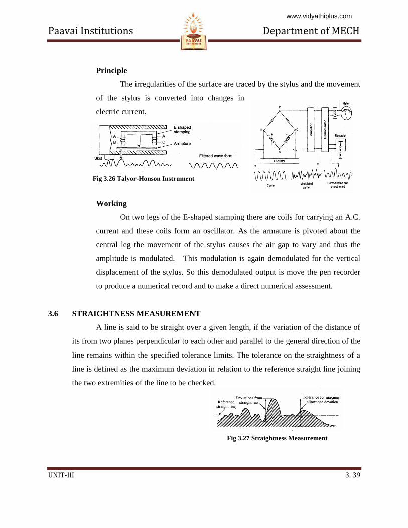
Principle
The irregularities of the surface are traced by the stylus and the movement
of the stylus is converted into changes in
electric current.
Working
On two legs of the E-shaped stamping there are coils for carrying an A.C.
current and these coils form an oscillator. As the armature is pivoted about the
central leg the movement of the stylus causes the air gap to vary and thus the
amplitude is modulated. This modulation is again demodulated for the vertical
displacement of the stylus. So this demodulated output is move the pen recorder
to produce a numerical record and to make a direct numerical assessment.
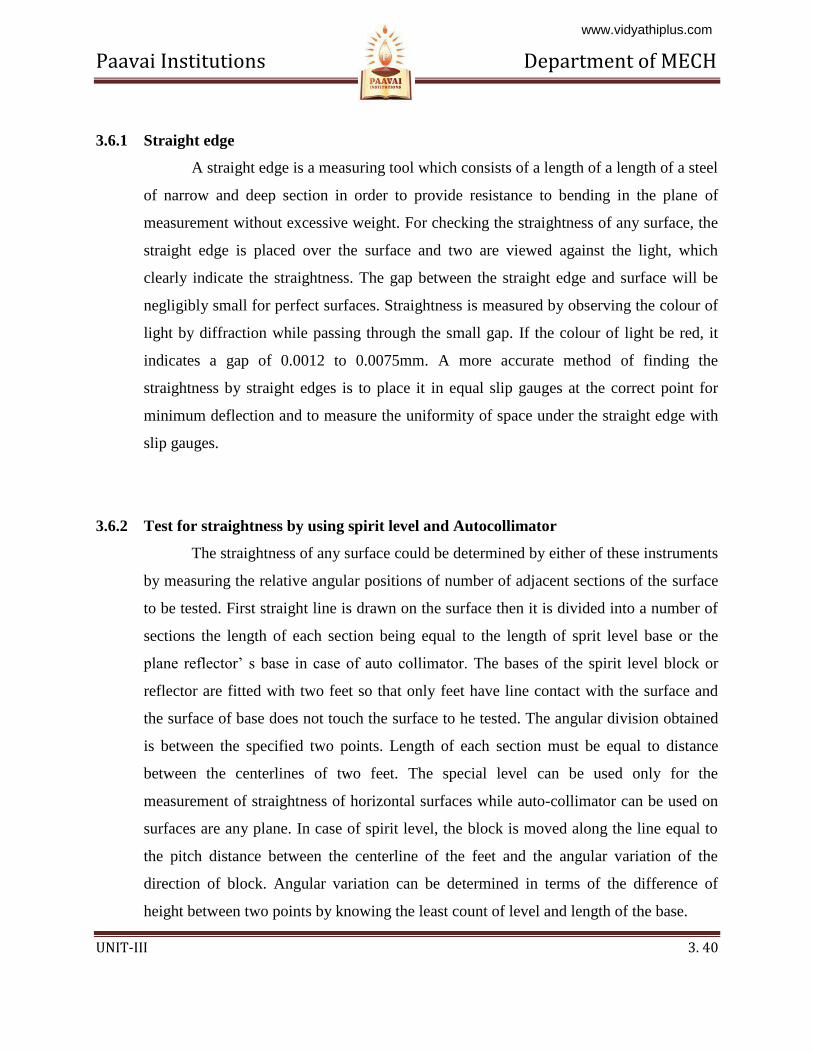
3.6 STRAIGHTNESS MEASUREMENT
A line is said to be straight over a given length, if the variation of the distance of
its from two planes perpendicular to each other and parallel to the general direction of the
line remains within the specified tolerance limits. The tolerance on the straightness of a
line is defined as the maximum deviation in relation to the reference straight line joining
the two extremities of the line to be checked.
Fig 3.26 Talyor-Honson Instrument
Fig 3.27 Straightness Measurement
www.vidyathiplus.com
Paavai Institutions Department of MECH
UNIT-III 3. 40
3.6.1 Straight edge
A straight edge is a measuring tool which consists of a length of a length of a steel
of narrow and deep section in order to provide resistance to bending in the plane of
measurement without excessive weight. For checking the straightness of any surface, the
straight edge is placed over the surface and two are viewed against the light, which
clearly indicate the straightness. The gap between the straight edge and surface will be
negligibly small for perfect surfaces. Straightness is measured by observing the colour of
light by diffraction while passing through the small gap. If the colour of light be red, it
indicates a gap of 0.0012 to 0.0075mm. A more accurate method of finding the
straightness by straight edges is to place it in equal slip gauges at the correct point for
minimum deflection and to measure the uniformity of space under the straight edge with
slip gauges.
3.6.2 Test for straightness by using spirit level and Autocollimator
The straightness of any surface could be determined by either of these instruments
by measuring the relative angular positions of number of adjacent sections of the surface
to be tested. First straight line is drawn on the surface then it is divided into a number of
sections the length of each section being equal to the length of sprit level base or the
plane reflector’ s base in case of auto collimator. The bases of the spirit level block or
reflector are fitted with two feet so that only feet have line contact with the surface and
the surface of base does not touch the surface to he tested. The angular division obtained
is between the specified two points. Length of each section must be equal to distance
between the centerlines of two feet. The special level can be used only for the
measurement of straightness of horizontal surfaces while auto-collimator can be used on
surfaces are any plane. In case of spirit level, the block is moved along the line equal to
the pitch distance between the centerline of the feet and the angular variation of the
direction of block. Angular variation can be determined in terms of the difference of
height between two points by knowing the least count of level and length of the base.
www.vidyathiplus.com
Paavai Institutions Department of MECH
UNIT-III 3. 41
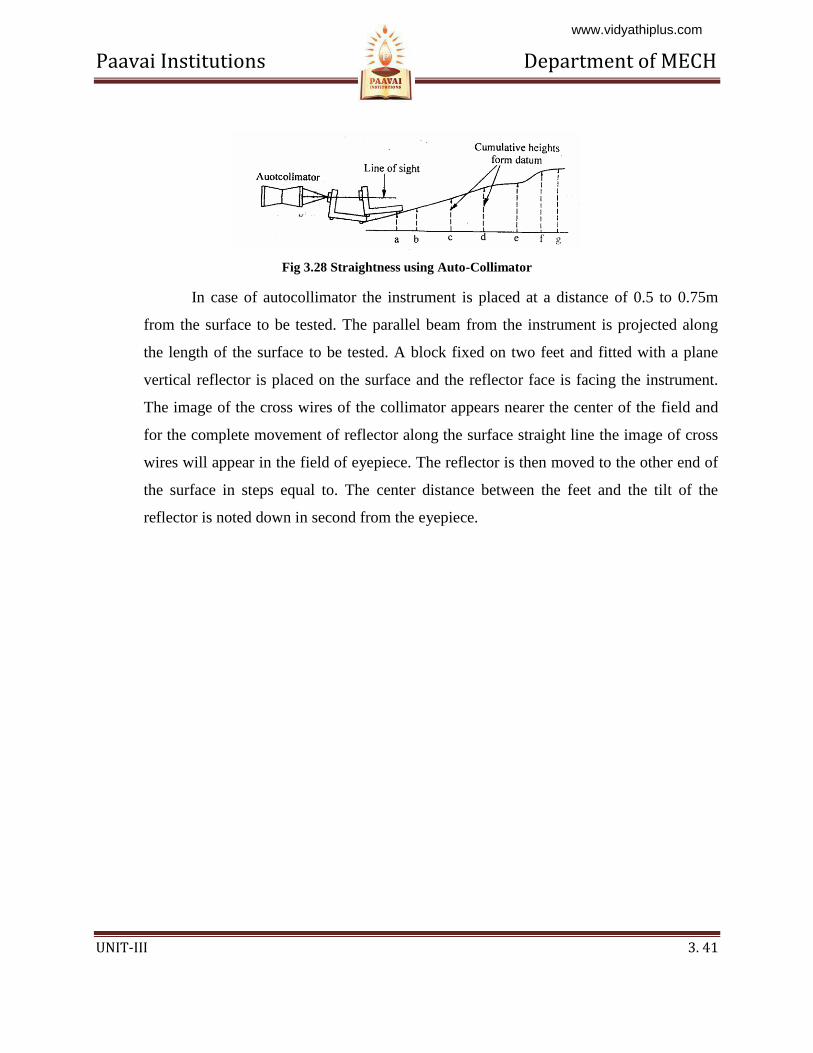
Fig 3.28 Straightness using Auto-Collimator
In case of autocollimator the instrument is placed at a distance of 0.5 to 0.75m
from the surface to be tested. The parallel beam from the instrument is projected along
the length of the surface to be tested. A block fixed on two feet and fitted with a plane
vertical reflector is placed on the surface and the reflector face is facing the instrument.
The image of the cross wires of the collimator appears nearer the center of the field and
for the complete movement of reflector along the surface straight line the image of cross
wires will appear in the field of eyepiece. The reflector is then moved to the other end of
the surface in steps equal to. The center distance between the feet and the tilt of the
reflector is noted down in second from the eyepiece.
www.vidyathiplus.com
Paavai Institutions Department of MECH
UNIT-III 3. 42
3.7 FLATNESS TESTING
Flatness testing is possible by comparing the surface with an accurate surface.
This method is suitable for small plates and not for large surfaces. Mathematically
flatness error of a surface states that the departure from flatness is the minimum
separation of a pair of parallel planes which will contain all points on the Surface. The
figure which shows that a surface can be considered to be composed of an infinitely large
number of lines. The surface will be flat only if all the lines are straight and they lie in the
same plane. In the case of rectangular table arc the lines are straight and parallel to the
sides of the rectangle in both the perpendicular direction. Even it is not plat, but concave
and convex along two diagonals. For verification, it is essential to measure the
straightness of diagonals in addition to the lines parallel to the sides.
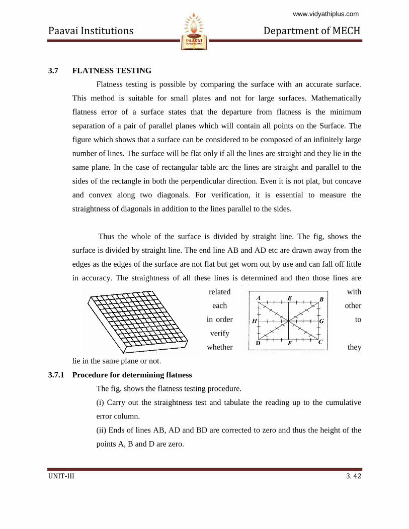
Thus the whole of the surface is divided by straight line. The fig, shows the
surface is divided by straight line. The end line AB and AD etc are drawn away from the
edges as the edges of the surface are not flat but get worn out by use and can fall off little
in accuracy. The straightness of all these lines is determined and then those lines are
related with
each other
in order to
verify
whether they
lie in the same plane or not.
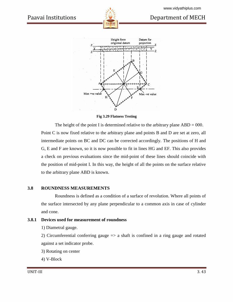
3.7.1 Procedure for determining flatness
The fig. shows the flatness testing procedure.
(i) Carry out the straightness test and tabulate the reading up to the cumulative
error column.
(ii) Ends of lines AB, AD and BD are corrected to zero and thus the height of the
points A, B and D are zero.
www.vidyathiplus.com
Paavai Institutions Department of MECH
UNIT-III 3. 43
Fig 3.29 Flatness Testing
The height of the point I is determined relative to the arbitrary plane ABD = 000.
Point C is now fixed relative to the arbitrary plane and points B and D are set at zero, all
intermediate points on BC and DC can be corrected accordingly. The positions of H and
G, E and F are known, so it is now possible to fit in lines HG and EF. This also provides
a check on previous evaluations since the mid-point of these lines should coincide with
the position of mid-point I. In this way, the height of all the points on the surface relative
to the arbitrary plane ABD is known.
3.8 ROUNDNESS MEASUREMENTS
Roundness is defined as a condition of a surface of revolution. Where all points of
the surface intersected by any plane perpendicular to a common axis in case of cylinder
and cone.
3.8.1 Devices used for measurement of roundness
1) Diametral gauge.
2) Circumferential conferring gauge => a shaft is confined in a ring gauge and rotated
against a set indicator probe.
3) Rotating on center
4) V-Block
www.vidyathiplus.com
Paavai Institutions Department of MECH
UNIT-III 3. 44
5) Three-point probe.
6) Accurate spindle.
1. Diametral method
The measuring plungers are located 180° a part and the diameter is measured at
several places. This method is suitable only when the specimen is elliptical or has an even
number of lobes. Diametral check does not necessarily disclose effective size or
roundness. This method is unreliable in determining roundness.
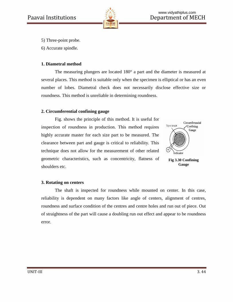
2. Circumferential confining gauge
Fig. shows the principle of this method. It is useful for
inspection of roundness in production. This method requires
highly accurate master for each size part to be measured. The
clearance between part and gauge is critical to reliability. This
technique does not allow for the measurement of other related
geometric characteristics, such as concentricity, flatness of
shoulders etc.
3. Rotating on centers
The shaft is inspected for roundness while mounted on center. In this case,
reliability is dependent on many factors like angle of centers, alignment of centres,
roundness and surface condition of the centres and centre holes and run out of piece. Out
of straightness of the part will cause a doubling run out effect and appear to be roundness
error.
Fig 3.30 Confining
Gauge
www.vidyathiplus.com
Paavai Institutions Department of MECH
UNIT-III 3. 45
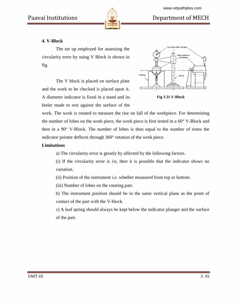
4. V-Block
The set up employed for assessing the
circularity error by using V Block is shown in
fig.
The V block is placed on surface plate
and the work to be checked is placed upon it.
A diameter indicator is fixed in a stand and its
feeler made to rest against the surface of the
work. The work is rotated to measure the rise on fall of the workpiece. For determining
the number of lobes on the work piece, the work piece is first tested in a 60° V-Block and
then in a 90° V-Block. The number of lobes is then equal to the number of times the
indicator pointer deflects through 360° rotation of the work piece.
Limitations
a) The circularity error is greatly by affected by the following factors.
(i) If the circularity error is i\e, then it is possible that the indicator shows no
variation.
(ii) Position of the instrument i.e. whether measured from top or bottom.
(iii) Number of lobes on the rotating part.
b) The instrument position should be in the same vertical plane as the point of
contact of the part with the V-block.
c) A leaf spring should always be kept below the indicator plunger and the surface
of the part.
Fig 3.31 V-Block
www.vidyathiplus.com
Paavai Institutions Department of MECH
UNIT-III 3. 46
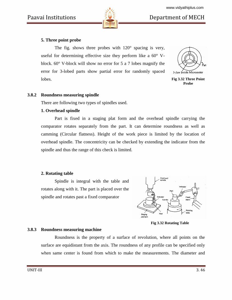
5. Three point probe
The fig. shows three probes with 120° spacing is very,
useful for determining effective size they perform like a 60° V-
block. 60° V-block will show no error for 5 a 7 lobes magnify the
error for 3-lobed parts show partial error for randomly spaced
lobes.
3.8.2 Roundness measuring spindle
There are following two types of spindles used.
1. Overhead spindle
Part is fixed in a staging plat form and the overhead spindle carrying the
comparator rotates separately from the part. It can determine roundness as well as
camming (Circular flatness). Height of the work piece is limited by the location of
overhead spindle. The concentricity can be checked by extending the indicator from the
spindle and thus the range of this check is limited.
2. Rotating table
Spindle is integral with the table and
rotates along with it. The part is placed over the
spindle and rotates past a fixed comparator
3.8.3 Roundness measuring machine
Roundness is the property of a surface of revolution, where all points on the
surface are equidistant from the axis. The roundness of any profile can be specified only
when same center is found from which to make the measurements. The diameter and
Fig 3.32 Three Point
Probe
Fig 3.32 Rotating Table
www.vidyathiplus.com
Paavai Institutions Department of MECH
UNIT-III 3. 47
roundness are measured by different method and instruments. For measurement of
diameter it is done statically, for measuring roundness, rotation is always necessary.
Roundness measuring instruments are two types.
1. Rotating pick up type.
2. Turn table type.
These are accurate, speed and reliable measurements. The rotating pick up type
the work piece is stationary and the pickup revolved. In the turn table the work piece is
rotated and pick up is stationery. On the rotating type, spindle is designed to carry the
light load of the pickup. The weight of the work piece, being stationary and is easy to
make. In the turn table type the pickup is not associated with the spindle. This is easier to
measure roundness. Reposition the pickup has no effects on the reference axis.
The pickup converts the circuit movement of the stylus into electrical signal,
which is processed and amplified and fed to a polar recorder. A microcomputer is
incorporated with integral visual display unit and system is controlled from compact
keyboards, which increases the system versatility, scope and speed of analysis. System is
programmed to access the roundness of work piece with respect to any four of the
internationality recognized reference circles. A visual display of work piece profile can
be obtained. Work piece can be assessed over a circumference, and with undercut surface
or an interrupted surface with sufficient data the reference circle can be fitted to the
profile. The program also provides functions like auto centering, auto ranging, auto
calibration and concentricity.
3.8.4 Modern Roundness Measuring Instruments
This is based on use of microprocessor to provide measurements of roundness
quickly and in a simple way; there is no need of assessing out of roundness. Machine can
do centering automatically and calculate roundness and concentricity, straightness and
provide visual and digital displays. A computer is used to speed up calculations and
provide the stand reference circle.
www.vidyathiplus.com
Paavai Institutions Department of MECH
UNIT-III 3. 48
(i) Least square circle
The sum of the squares of a sufficient no. of equally spaced radial ordinates
measured from the circle to the profile has minimum value. The center of such circle is
referred to as the least square center. Out of roundness is defined as the radial distance of
the maximum peak from the circle (P) plus the distance of the maximum valley from this
circle.
(ii) Minimum zone or Minimum radial separation circle
These are two concentric circles. The value of the out of roundness is the radial
distance between the two circles. The center of such a circle is termed as the minimum
zone center. These circles can be found by using a template.
(iii) Maximum inscribed circle
This is the largest circle. Its center and radius can be found by trial and error by
compare or by template or computer. Since V = 0 there is no valleys inside the circle.
(iv)Minimum circumscribed circles
This is the smallest circle. Its center and radius can be found by the previous
method since P = 0 there is no peak outside the circle. The radial distance between the
minimum circumscribing circle and the maximum inscribing circle is the measure of the
error circularity. The fig shows the trace produced by a recording instrument.
This trace to draw concentric circles on the polar graph which pass through the
maximum and minimum points in such way that the radial distance be minimum
circumscribing circle containing the trace or the n inscribing circle which can fitted into
the trace is minimum. The radial distance between the outer and inner circle is minimum
is considered for determining the circularity error. Assessment of roundness can be done
by templates. The out off roundness is defined as the radial distance of the maximum
peak (P) from the least square circle plus the distance of the maximum valley (V) from
www.vidyathiplus.com

Paavai Institutions Department of MECH
UNIT-III 3. 49
the least square circle. All roundness analysis can be performed by harmonic and slope
analysis.
www.vidyathiplus.com
Paavai Institutions Department of MECH
UNIT-III 3. 50
QUESTION BANK
Part-A (2 Marks)
1. Name the various methods for measuring effective diameter
2. Name the various methods for measuring pitch diameter.
3. Name the two corrections are to be applied in the measurement of effective diameter.
4. What is best size of wire?
5. Define. Drunken thread
6. What is the effect of flank angle error?
7. What are the applications of toolmaker's microscope?
8. Define: Periodic error.
9. What are the commonly used forms of gear teeth?
10. What are the types of gears?
11. Define: Module
12. Define: Lead angle
13. What are the various methods used for measuring the gear tooth thickness?
14. Name four gear errors.
15. Name the method used for checking the pitch of the gear.
Part-B (16 Marks)
1. Explain the construction and working of floating carriage micrometer
2. How are the major and minor diameters of thread measured?
3. Define various terminologies related with screw thread
4. Define various terminologies related with screw gears
5. Explain any two taper measurements method.
6. Explain the construction and working of Gear tooth vernier
7. Explain a method used in the measurement of surface finish and flatness
8. How to measure the pitch of the screw thread by using the tool maker’s microscope?
Discuss in detail.
www.vidyathiplus.com
Paavai Institutions Department of MECH
UNIT-III 3. 51
9. Describe the method of inspecting the profile of spur gear by using involute measuring
machine.
10. How to check the composite errors of the gear by using Parkinson gear testing machine?
Explain it in detail?
11. Briefly describe major, minor and effective diameter of thread?
12. Describe the two wire method of finding the effective diameter of screw threads.
13. Describe the chordal thickness method using gear tooth vernier caliper.
14. Explain one method of assessing the straightness of a straight-edge.
15. Write notes on the types of irregularities of a circular part and mention its causes.
16. What is the ‘best wire size’? Derive an expression for the same in terms of the pitch and
angle of the thread,
17. Explain the principle of measuring gear tooth thickness by base tangent method. What is
the span length over 5 teeth of gear having 45 teeth module 4mm and pressure angle 20o
18. Derive the formula for measuring the effective diameter of thread by 3-wire method
19. With the aid of sketch describe the principle of operation of a rolling gear testing
machine.
www.vidyathiplus.com


![[4173]-101 - Vidyarthiplus](https://img.pdfslide.us/doc/110x75/61d6e0e3f9ec18156175b586/4173-101-vidyarthiplus.jpg)