Embed Size (px)
Citation preview
Strength of Materials
UNIT - II Shear Force Diagrams
and Bending Moment Diagrams
Lecture Number -1 Prof. M. J. Naidu
Mechanical Engineering DepartmentSmt. Kashibai Navale College of Engineering, Pune-41

Introduction
SFD and BMD used for analysis of Beam.
SFD- Variation of the shear force along the length.
BMD- Variation of the bending moment along the length.
Value of Shear Force use to calculate shear stress
Value of Bending moment use to calculate Bending Stress
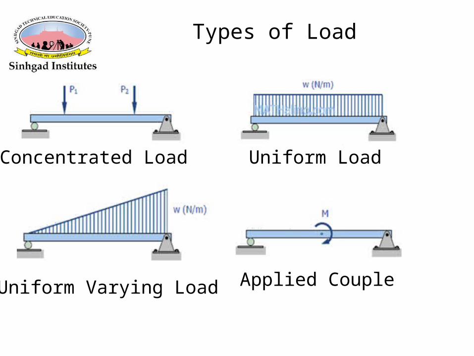
Types of Load
Concentrated Load Uniform Load
Uniform Varying Load Applied Couple
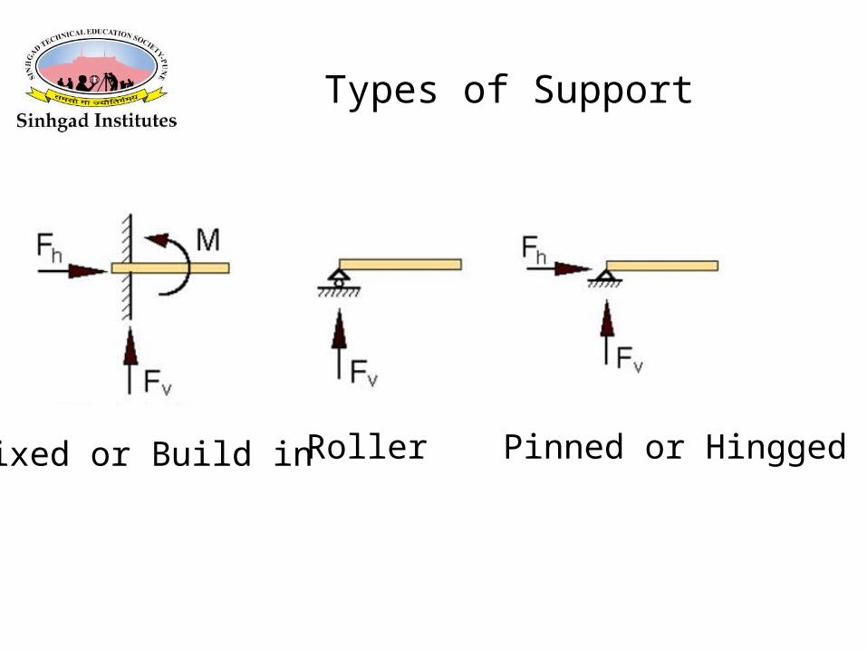
Types of Support
Fixed or Build in Roller Pinned or Hingged
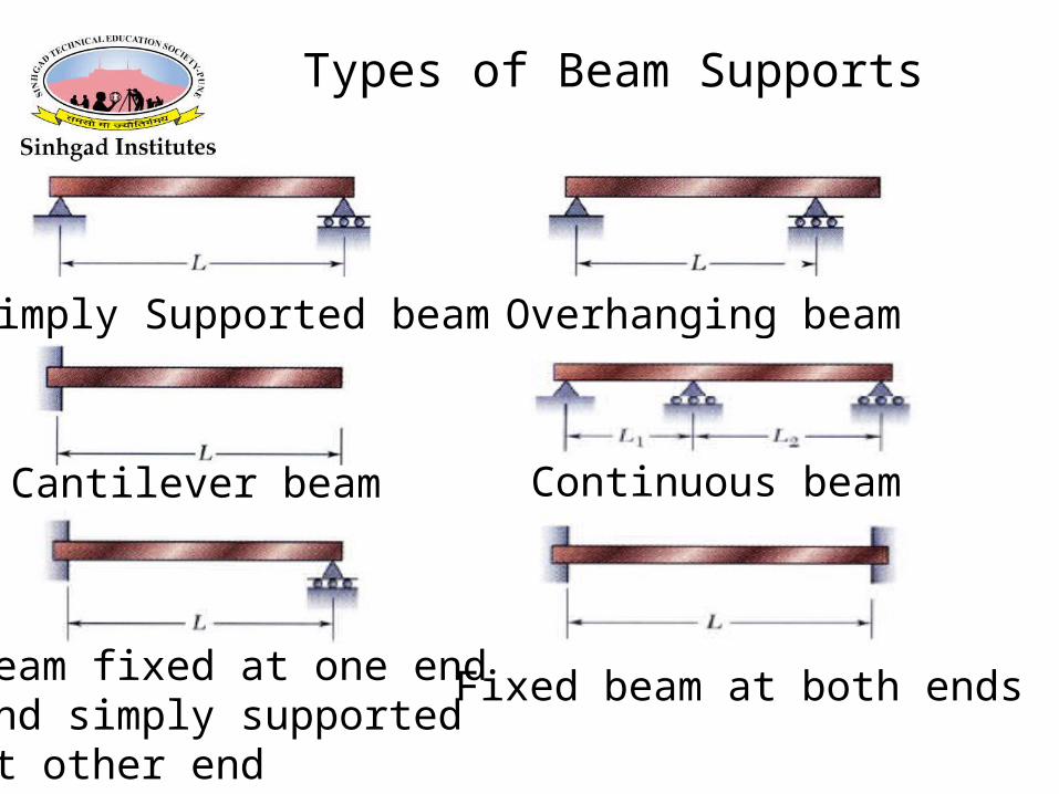
Types of Beam Supports
Simply Supported beam Overhanging beam
Cantilever beam Continuous beam
Beam fixed at one end and simply supported at other end
Fixed beam at both ends
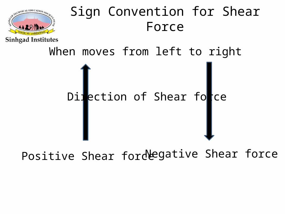
Sign Convention for Shear Force
Positive Shear force Negative Shear force
Direction of Shear force
When moves from left to right
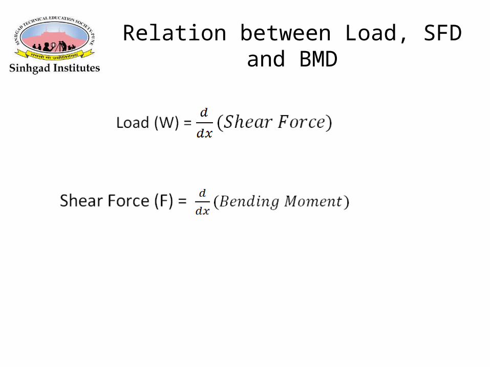
Relation between Load, SFD and BMD
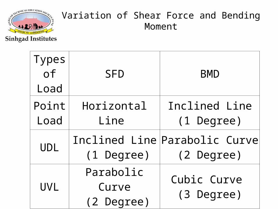
Variation of Shear Force and Bending Moment
Types of Load SFD BMD
Point Load Horizontal Line Inclined Line
(1 Degree)
UDL Inclined Line (1 Degree)
Parabolic Curve (2 Degree)
UVL Parabolic Curve (2 Degree)
Cubic Curve (3 Degree)
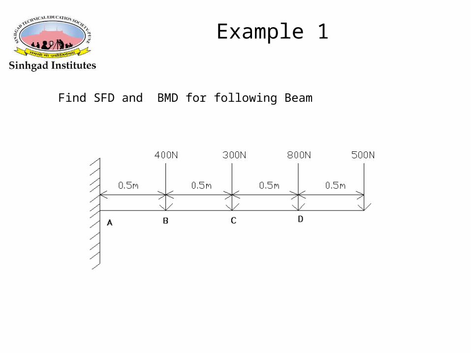
Example 1
Find SFD and BMD for following Beam
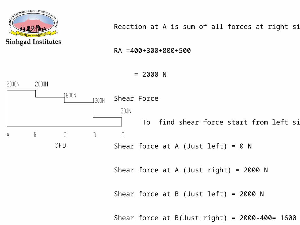
Reaction at A is sum of all forces at right side of A
RA =400+300+800+500
= 2000 N
Shear Force
To find shear force start from left side
Shear force at A (Just left) = 0 N
Shear force at A (Just right) = 2000 N
Shear force at B (Just left) = 2000 N
Shear force at B(Just right) = 2000-400= 1600 N
Shear force at C (Just left) = 1600 N
Shear force at C (Just right) = 1600-300= 1300 N
Shear force at D (Just left) = 1300 N
Shear force at D (Just right) = 1300-800= 500 N
Shear force at E (Just left) = 500 N
Shear force at E (Just right) = 500-500 N= 0 N
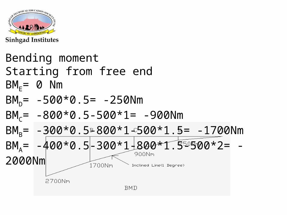
Bending momentStarting from free endBME= 0 NmBMD= -500*0.5= -250NmBMC= -800*0.5-500*1= -900NmBMB= -300*0.5-800*1-500*1.5= -1700NmBMA= -400*0.5-300*1-800*1.5-500*2= -2000Nm
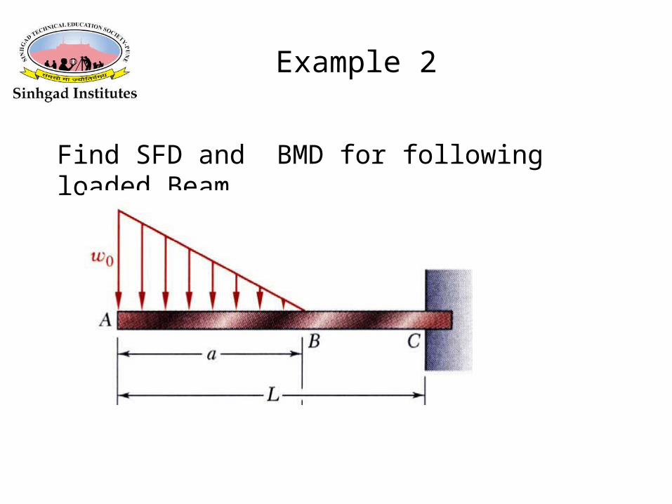
Example 2
Find SFD and BMD for following loaded Beam
HINTS
• Take the entire beam as a free body.• Determine the reactions at C.• Apply the relationship between shear and load• Develop the shear diagram..• Apply the relationship between bending moment
and shear• Develop the bending moment diagram.
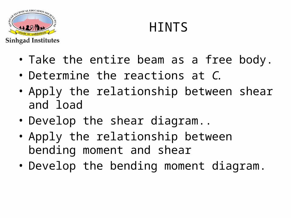
• Taking the entire beam as a free body, determine the reactions at C.
• Result from integration of the load and shear distributions should be equivalent.
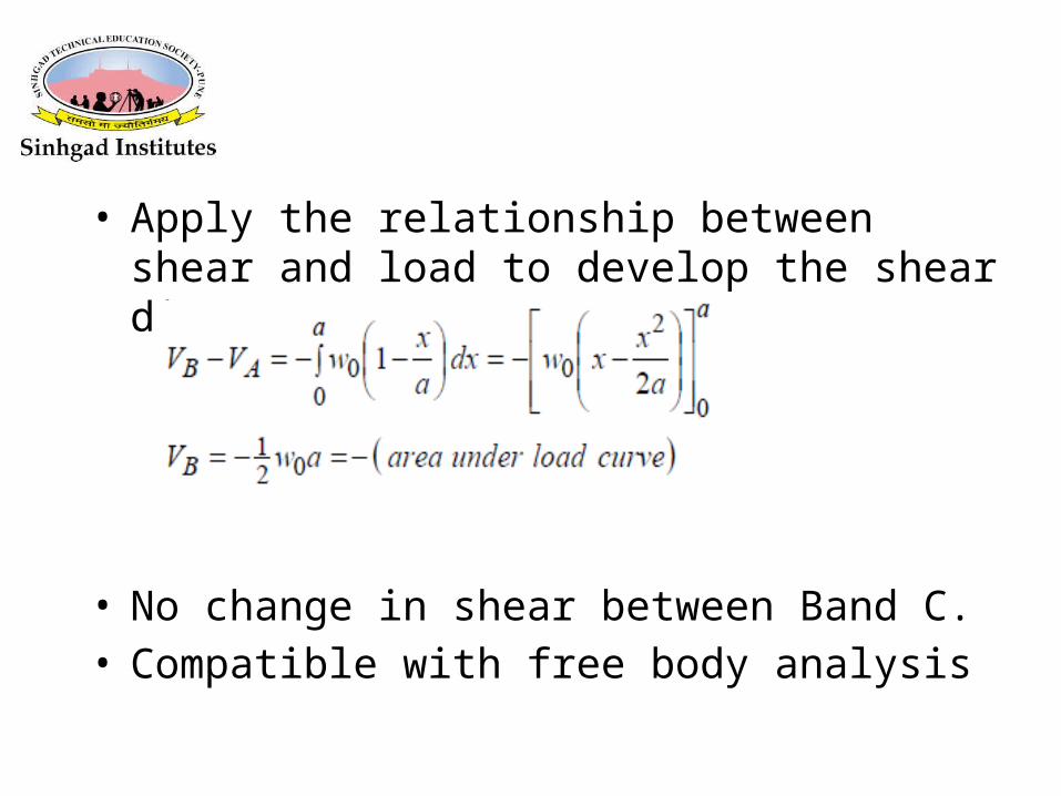
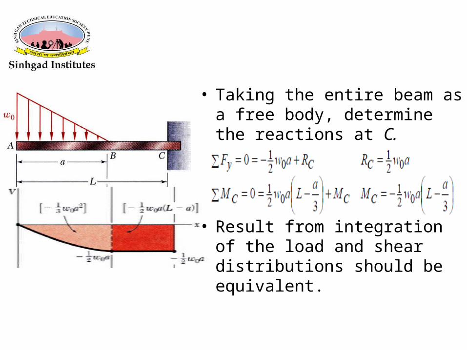
• Apply the relationship between shear and load to develop the shear diagram.
• No change in shear between Band C.• Compatible with free body analysis
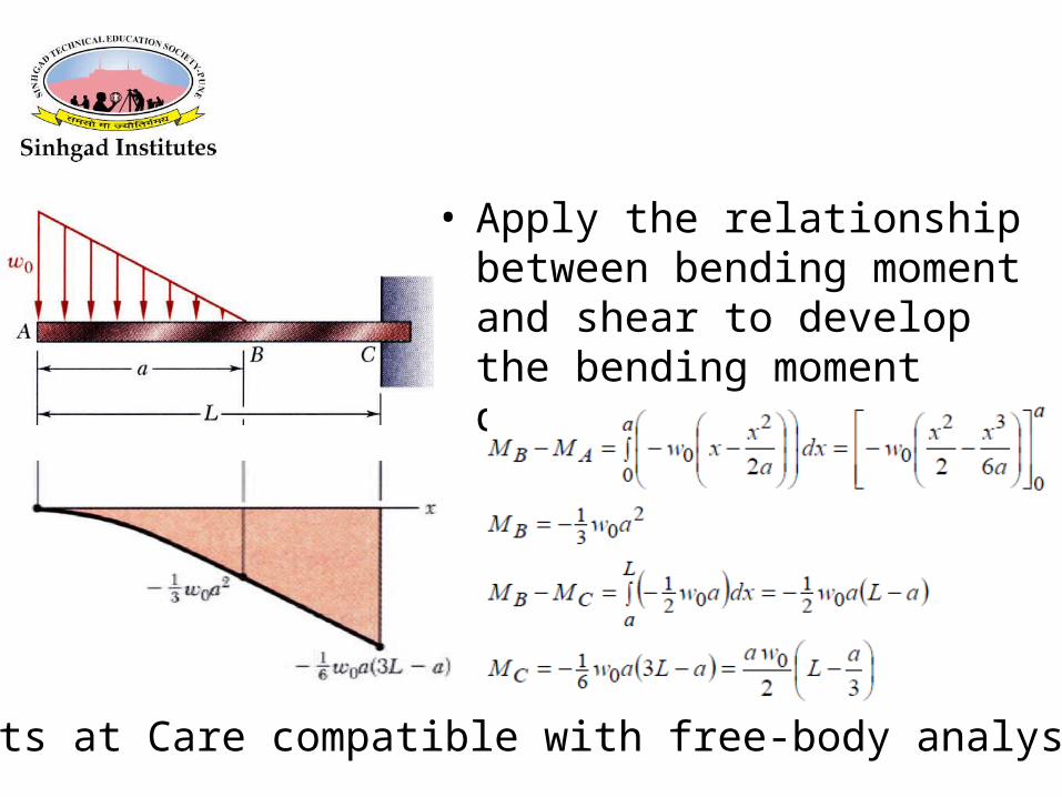
• Apply the relationship between bending moment and shear to develop the bending moment diagram.
• Results at Care compatible with free-body analysis
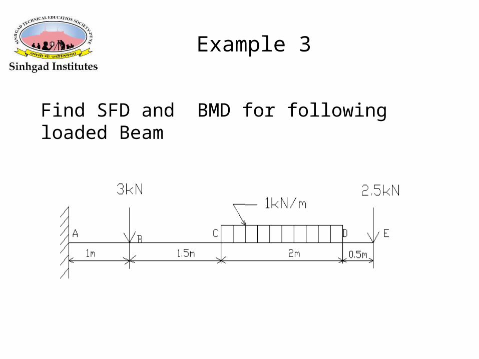
Example 3
Find SFD and BMD for following loaded Beam
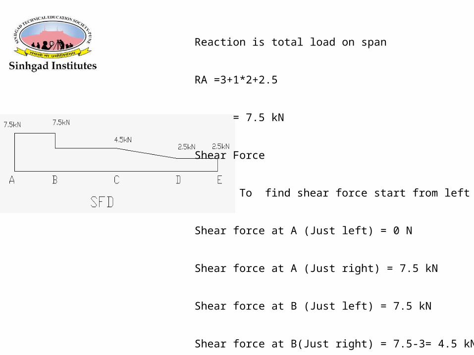
Reaction is total load on span
RA =3+1*2+2.5
= 7.5 kN
Shear Force
To find shear force start from left side
Shear force at A (Just left) = 0 N
Shear force at A (Just right) = 7.5 kN
Shear force at B (Just left) = 7.5 kN
Shear force at B(Just right) = 7.5-3= 4.5 kN
Shear force at C =4.5 kN
Shear force at D = 4.5- 1*2= 2.5 kN
Shear force at E (Just left) = 2.5 kN
Shear force at E (Just right) = 2.5-2.5= 0 kN
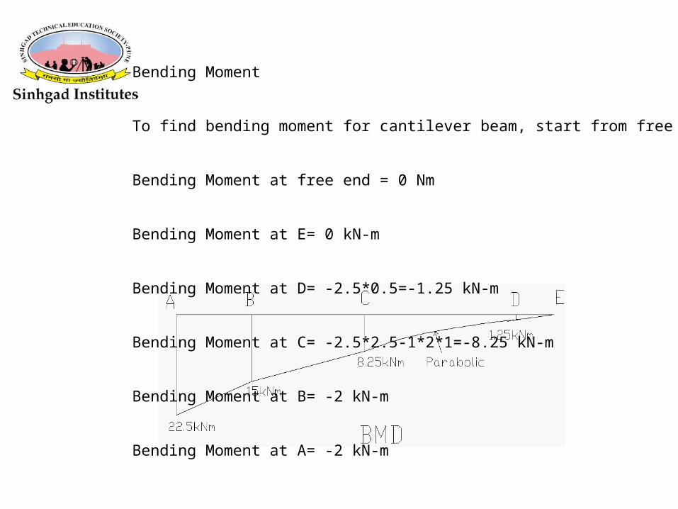
Bending Moment
To find bending moment for cantilever beam, start from free end
Bending Moment at free end = 0 Nm
Bending Moment at E= 0 kN-m
Bending Moment at D= -2.5*0.5=-1.25 kN-m
Bending Moment at C= -2.5*2.5-1*2*1=-8.25 kN-m
Bending Moment at B= -2 kN-m
Bending Moment at A= -2 kN-m
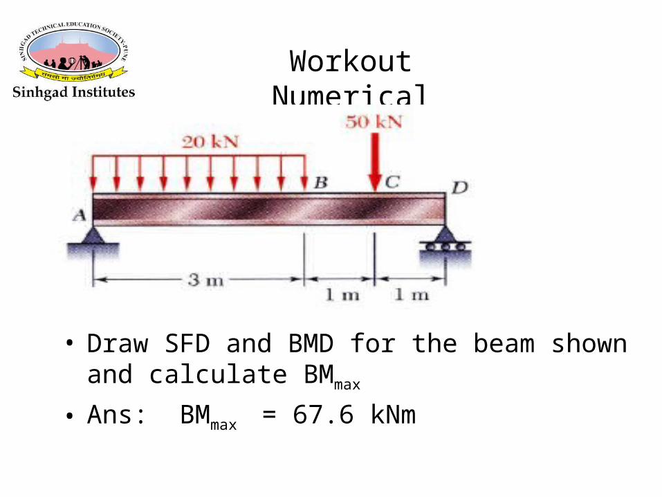
• Draw SFD and BMD for the beam shown and calculate BMmax
• Ans: BMmax = 67.6 kNm
Workout Numerical