Embed Size (px)
Citation preview
UNIT II
INTERNAL COMBUSTION ENGINES Classification of IC engine, IC engine components and functions. Valve timing diagram and port timing diagram. Comparison of two stroke and four stroke engines. Fuel supply systems, Ignition Systems, Performance calculation. Comparison of petrol & diesel engine. Fuels, Air-fuel ratio calculation, Knocking and Detonation. Lubrication system and cooling system. Exhaust gas analysis, pollution control norms. Numerical Problems.
INTRODUCTION As the name implies or suggests, the internal combustion engines (briefly written as IC
engines) are those engines in which the combustion of fuel takes place inside the engine cylinder. These are petrol, diesel, and gas engines. We have seen in steam engines or steam turbines that the fuel, fed into the cylinder, is in the form of steam which is already heated (or superheated), and is ready for working in the combustion cycle of the engine. But, in case of internal combustion engines, the combustion of fuel takes place inside the engine cylinder by a spark and produces very high temperature as compared to steam engines. The high temperature produced may ruin the metal of cylinder, valves, etc. It is, therefore, necessary to abstract some of heat from the engine cylinder. The abstraction of heat or the cooling of cylinder may be effected by the surrounding air as in case of a motor cycle or aeroplane engine; or by circulating water through jackets surrounding the cylinder barrel and cylinder head. The water cooling is mostly adopted for large pistons.
CLASSIFICATION OF IC ENGINES The internal combustion engines may be classified in many ways, but the following are
important from the subject point of view 1. According to the type of fuel used
(a) Petrol engines. (b) Diesel engines or oil engines, and (c) Gas engines.
2. According to the method of igniting the fuel (a) Spark ignition engines (briefly written as S.1. engines), (b) Compression ignition engines (briefly written as C.I. engines), and (c) Hot spot ignition engines
3. According to the number of strokes per cycle
(a) Four stroke cycle engines, and (b) Two stroke cycle engines.
4. According to the cycle of operation (a) Otto. cycle (also known as constant volume cycle) engines, (b) Diesel cycle (also known as constant pressure cycle) engines, and (c) Dual combustion cycle (also known as semi-diesel cycle) engines.
5. According to the speed of the engine
(a) Slow speed engines, (b) Medium speed engines, (c) High speed engines.
6. According to the cooling system
(a) Air-cooled engines. (b) Water-cooled engines. (c) Evaporative cooling engines.
7. According to the method of fuel injection
(a) Carburetor engines, (b) Air injection engines, (c) Airless or solid injection
engines. 8. According to the number of cylinders
(a) Single cylinder engines (b) Multi-cylinder engines. 9. According to the arrangement of cylinders
(a) Vertical engines, (b) Horizontal engines, (c) Radial engines, (d) In-line multi-cylinder engines, (e)V-type multi-cylinder engines, (j) Opposite-cylinder engines, (g) Opposite- piston engi
MAIN COMPONENTS OF IC ENGINES
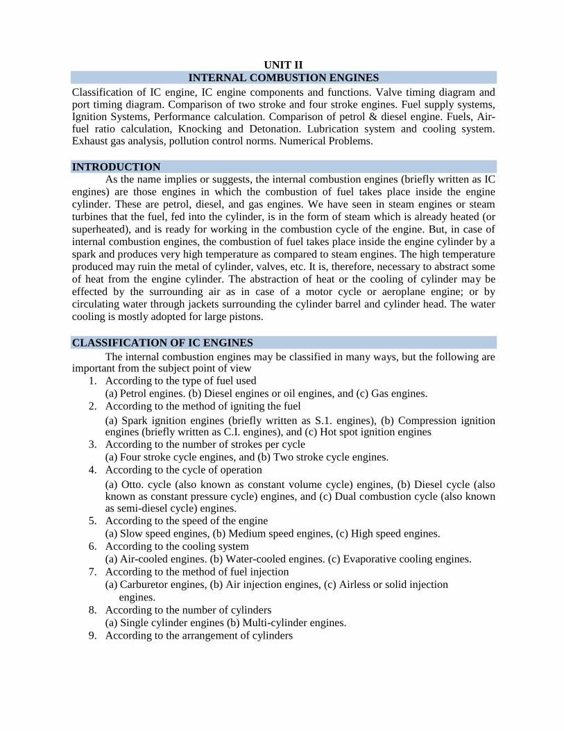
As a matter of fact, an IC engine consists of hundreds of different parts, which are important for its proper working. The description of all these parts is beyond the scope of this book. However, the main components, which are important from academic point of view, are shown and are discussed below: 1. Cylinder. It is one of the most important part of the engine, in which the piston moves to and fro in order to develop power. Generally, the engine cylinder has to withstand a high pressure (more than 50 bar) and temperature (more than 2000°C). Thus the materials for an engine cylinder should be such that it can retain sufficient strength at such a high pressure and temperature. For ordinary engines, the cylinder is made of ordinary cast iron. But for heavy duty engines, it is made of steel alloys or aluminium alloys. In case of multiple cylinder engines, the cylinders are cast in one block known as cylinder block.Sometimes, a liner or sleeve is inserted into the cylinder, which can be replaced when worn out. As the material required for liner is comparatively small, it can be made of alloy cast iron having long life and sufficient resistance to rapid wear and tear to the fast moving reciprocating parts. 2. Cylinder head: It is fitted on one end of the cylinder, and acts as a cover to close the
cylinder bore. Generally, the cylinder head contains inlet and exit valves for admitting fresh charge and exhausting the burnt gases. In petrol engines, the cylinder head also contains a spark plug for igniting the fuel-air mixture, towards the end of compression stroke. But in diesel engines, the cylinder head contains nozzle (i.e. fuel valve) for injecting the fuel into the cylinder. The cylinder head is, usually, cast as one piece and bolted to one end of the cylinder. Generally, the cylinder block and cylinder head are made from the same material. A copper or asbestos gasket is provided between the engine cylinder and cylinder head to make an air-tight joint.
3. Piston: It is considered as the heart of an l.c. engine, whose main function is to transmit the force exeI1ed by the burning of charge to the connecting rod. The pistons are generally made of aluminium alloys which are light in weight. They have good heat conducting property and also greater strength at higher temperatures. 4. Piston rings: These are circular rings and made of special steel alloys which retain elastic properties even at high temperatures. The piston rings are housed in the circumferential grooves provided on the outer surface of the piston. Generally, there are two sets of rings mounted for the piston. The function of the upper rings is to provide air tight seal to prevent leakage of the burnt gases into the lower portion. Similarly, the function of the lower rings is to provide effective seal to prevent leakage of the oil into the engine cylinder. 5. Connecting rod: It is a link between the piston and crankshaft, whose main function is to transmit force from the piston to the crankshaft. Moreover, it converts reciprocating motion of the piston into circular motion of the crankshaft, in the working stroke. The upper (i.e. smaller) end of the connecting rod is fitted to the piston and the lower (i.e. bigger) end to the crank. The special steel alloys or aluminium alloys are used for the manufacture of connecting rods. A special care is required for the design and manufacture of connecting rod, as it is subjected to alternatively compressive and tensile stresses as well as bending stresses. 6. Crankshaft: It is considered as the backbone of an l.c. engine whose function is to convert the reciprocating motion of the piston into the rotary motion with the help of connecting rod. This shaft contains one or more eccentric portions called cranks. That part of the crank, to which bigger end of the connecting rod is fitted, is called crank pin.It has been experienced that too many main bearings create difficulty of correct alignment. Special steel alloys are used for the manufacture of crankshaft. A special care is required for the design and manufacture of crankshaft. 7. Crank case: It is a cast iron case, which holds the cylinder and crankshaft of an I.c. engine. It also serves as a sump for the lubricating oil. The lower portion of the crank case is known as bed plate, which is fixed with the help of bolts. 8. Flywheel: It is a big wheel, mounted on the crankshaft, whose function is to maintain its speed constant. It is done by storing excess energy during the power stroke, which is returned during other strokes.
SEQUENCE OF OPERATIONS IN A CYCLE Strictly speaking, when an engine is working continuously, we may consider a cycle
starting from any stroke. We know that when the engine returns back to the stroke where it started we say that one cycle has been completed. The readers will find different sequence of operations in different books. But in this chapter, we shall consider the following sequence of operation in a cycle, which is widely used. I. Suction stroke: In this stroke, the fuel vapor in correct proportion, is supplied to the engine cylinder. 2. Compression stroke: In this stroke, the fuel vapor is compressed in the engine cylinder. 3. Expansion or working stroke: In this stroke, the fuel vapor is fired just before the compression is complete. It results in the sudden rise of pressure, due to expansion of the combustion products in the engine cylinder. This sudden rise of the pressure pushes the piston with a great force, and rotates the crankshaft. The crankshaft, in turn, drives the machine connected to it. 4. Exhaust stroke: In this stroke, the burnt gases (or combustion products) are exhausted
from the engine cylinder, so as to make space available for the fresh fuel vapor.
TWO STROKE AND FOUR STROKE CYCLE ENGINE
In a two-stroke engine, the working cycle is completed in two strokes of the piston or one revolution of the crankshaft. This is achieved by carrying out the suction and compression processes in one stroke (or more precisely in inward stroke), expansion and exhaust processes in the second stroke (or more precisely in outward stroke). In a four-stroke engine, the working cycle is completed in four-strokes of the piston or two-revolutions of the crankshaft. This is achieved by carrying out suction, compression, expansion and exhaust processes in each stroke. It will be interesting to know that from the thermodynamic point of view, there is no difference between two-stroke and four-stroke cycle engines. The difference is purely mechanical. Advantages and Disadvantage of Two-stroke over Four-stroke Cycle Engines Advantages
1. A two stroke cycle engine gives twice the number of power strokes than the four stroke cycle engine at the same engine speed. Theoretically, a two-stroke cycle engine should develop twice the power as that of a four-stroke cycle engine. But in actual practice, a two-stroke cycle engine develops 1.7 to 1.8 times greater value for slow speed engines the power developed by four-stroke cycle engine of the same dimensions and speed. This is due to lower compression ratio and effective stroke being less than the theoretical stroke.
2. For the same power developed, a two-stroke cycle engine is lighter, less bulky and occupies less floor area. Thus it makes, a two-stroke cycle engine suitable for marine engines and other light vehicles.
3. As the number of working strokes in a two-stroke cycle engine are twice than the four-stroke cycle engine, so the turning moment of a two-stroke cycle engine is more uniform. Thus it makes a two-stroke cycle engine to have a lighter flywheel and foundations. This also leads to a higher mechanical efficiency of a two-stroke cycle engine.
4. The initial cost of a two-stroke cycle engine is considerably less than a four-stroke cycle engine.
5. The mechanism of a two-stroke cycle engine is much simpler than a four-stroke cycle engine.
6. The two-stroke cycle engines are much easier to start. Disadvantages
1. Thermal efficiency of a two-stroke cycle engine is less than that a four-stroke cycle engine, because a two-stroke cycle engine has less compression ratio than that of a four-stroke cycle engine.
2. Overall efficiency of a two stroke cycle engine is also less than that of a four-stroke cycle engine because in a two-stroke cycle, inlet and exhaust ports remain open simultaneously for some time. In spite of careful design, a small quantity of charge is lost from the engine cylinder.
3. In case of a two-stroke cycle engine, the number of power strokes is twice as those of a four-stroke cycle engine. Thus the capacity of the cooling system must be higher. Beyond a certain limit, the cooling capacity offers a considerable difficulty. Moreover, there is a greater wear and tear in a two-stroke cycle engine.
4. The consumption of lubricating oil is large in a two-stroke cycle engine because of high operating temperature.
5. The exhaust gases in a two-stroke cycle engine create noise, because of short time available for their exhaust.
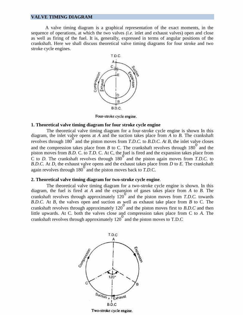
VALVE TIMING DIAGRAM
A valve timing diagram is a graphical representation of the exact moments, in the sequence of operations, at which the two valves (i.e. inlet and exhaust valves) open and close as well as firing of the fuel. It is, generally, expressed in terms of angular positions of the crankshaft. Here we shall discuss theoretical valve timing diagrams for four stroke and two stroke cycle engines.
1. Theoretical valve timing diagram for four stroke cycle engine The theoretical valve timing diagram for a four-stroke cycle engine is shown In this
diagram, the inlet valve opens at A and the suction takes place from A to B. The crankshaft
revolves through 1800 and the piston moves from T.D.C. to B.D.C. At B, the inlet valve closes
and the compression takes place from B to C. The crankshaft revolves through 1800 and the
piston moves from B.D. C. to T.D. C. At C, the fuel is fired and the expansion takes place from
C to D. The crankshaft revolves through 1800 and the piston again moves from T.D.C. to
B.D.C. At D, the exhaust valve opens and the exhaust takes place from D to E. The crankshaft
again revolves through 1800 and the piston moves back to T.D.C.
2. Theoretical valve timing diagram for two-stroke cycle engine.
The theoretical valve timing diagram for a two-stroke cycle engine is shown. In this diagram, the fuel is fired at A and the expansion of gases takes place from A to B. The
crankshaft revolves through approximately 1200 and the piston moves from T.D.C. towards
B.D.C. At B, the valves open and suction as well as exhaust take place from B to C. The
crankshaft revolves through approximately 1200 and the piston moves first to B.D.C and then
little upwards. At C. both the valves close and compression takes place from C to A. The
crankshaft revolves through approximately 1200 and the piston moves to T.D.C
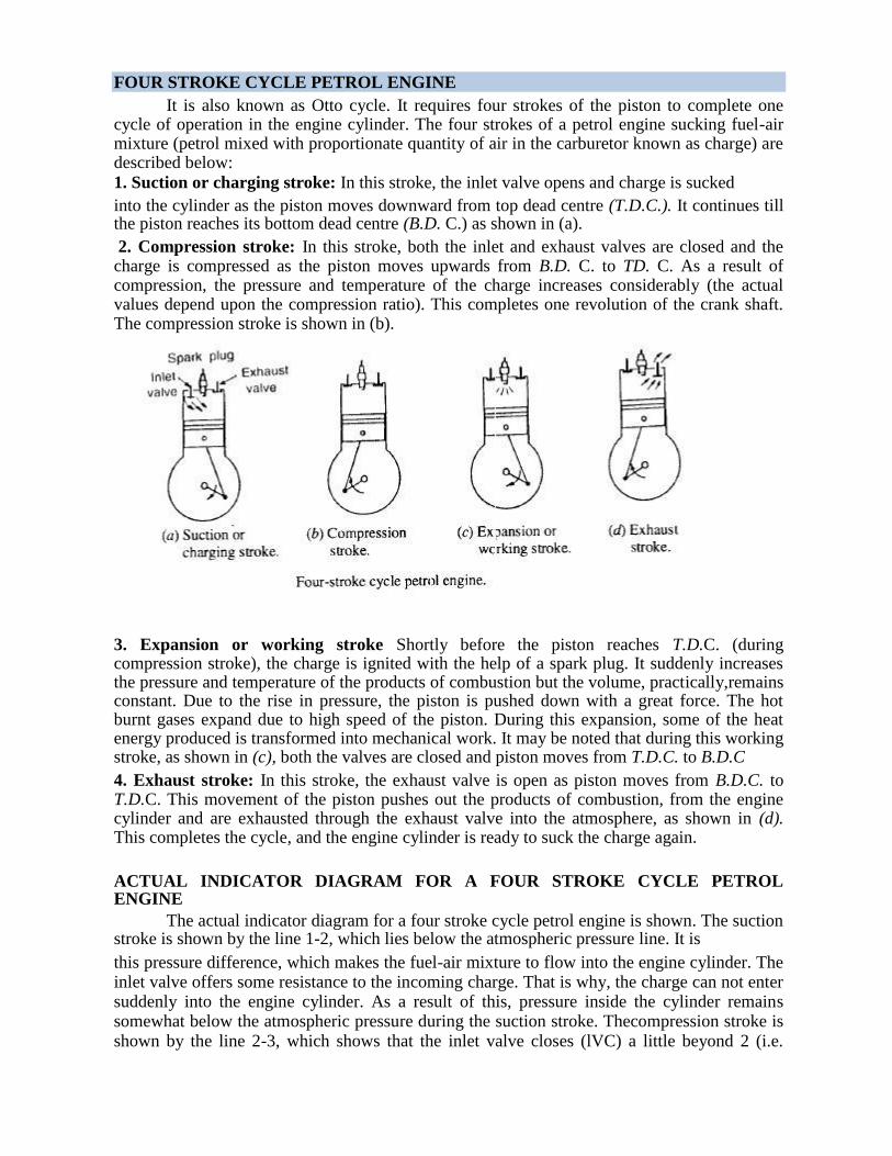
FOUR STROKE CYCLE PETROL ENGINE It is also known as Otto cycle. It requires four strokes of the piston to complete one
cycle of operation in the engine cylinder. The four strokes of a petrol engine sucking fuel-air mixture (petrol mixed with proportionate quantity of air in the carburetor known as charge) are described below: 1. Suction or charging stroke: In this stroke, the inlet valve opens and charge is sucked into the cylinder as the piston moves downward from top dead centre (T.D.C.). It continues till the piston reaches its bottom dead centre (B.D. C.) as shown in (a). 2. Compression stroke: In this stroke, both the inlet and exhaust valves are closed and the charge is compressed as the piston moves upwards from B.D. C. to TD. C. As a result of compression, the pressure and temperature of the charge increases considerably (the actual values depend upon the compression ratio). This completes one revolution of the crank shaft. The compression stroke is shown in (b).
3. Expansion or working stroke Shortly before the piston reaches T.D.C. (during compression stroke), the charge is ignited with the help of a spark plug. It suddenly increases the pressure and temperature of the products of combustion but the volume, practically,remains constant. Due to the rise in pressure, the piston is pushed down with a great force. The hot burnt gases expand due to high speed of the piston. During this expansion, some of the heat energy produced is transformed into mechanical work. It may be noted that during this working stroke, as shown in (c), both the valves are closed and piston moves from T.D.C. to B.D.C 4. Exhaust stroke: In this stroke, the exhaust valve is open as piston moves from B.D.C. to T.D.C. This movement of the piston pushes out the products of combustion, from the engine cylinder and are exhausted through the exhaust valve into the atmosphere, as shown in (d). This completes the cycle, and the engine cylinder is ready to suck the charge again.
ACTUAL INDICATOR DIAGRAM FOR A FOUR STROKE CYCLE PETROL ENGINE
The actual indicator diagram for a four stroke cycle petrol engine is shown. The suction stroke is shown by the line 1-2, which lies below the atmospheric pressure line. It is this pressure difference, which makes the fuel-air mixture to flow into the engine cylinder. The inlet valve offers some resistance to the incoming charge. That is why, the charge can not enter suddenly into the engine cylinder. As a result of this, pressure inside the cylinder remains somewhat below the atmospheric pressure during the suction stroke. Thecompression stroke is shown by the line 2-3, which shows that the inlet valve closes (lVC) a little beyond 2 (i.e.
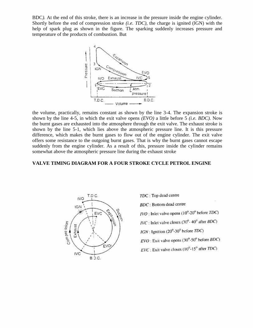
BDC). At the end of this stroke, there is an increase in the pressure inside the engine cylinder. Shortly before the end of compression stroke (i.e. TDC), the charge is ignited (lGN) with the help of spark plug as shown in the figure. The sparking suddenly increases pressure and temperature of the products of combustion. But
the volume, practically, remains constant as shown by the line 3-4. The expansion stroke is shown by the line 4-5, in which the exit valve opens (EVO) a little before 5 (i.e. BDC). Now the burnt gases are exhausted into the atmosphere through the exit valve. The exhaust stroke is shown by the line 5-1, which lies above the atmospheric pressure line. It is this pressure difference, which makes the burnt gases to flow out of the engine cylinder. The exit valve offers some resistance to the outgoing burnt gases. That is why the burnt gases cannot escape suddenly from the engine cylinder. As a result of this, pressure inside the cylinder remains somewhat above the atmospheric pressure line during the exhaust stroke
VALVE TIMING DIAGRAM FOR A FOUR STROKE CYCLE PETROL ENGINE
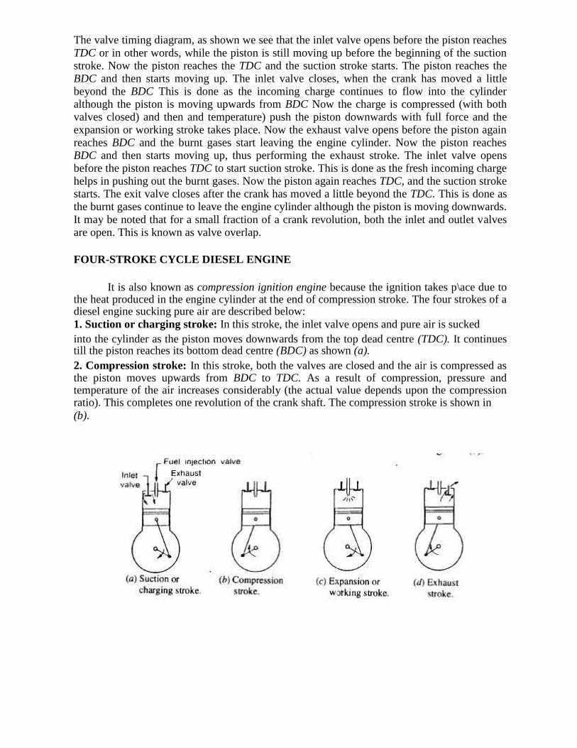
The valve timing diagram, as shown we see that the inlet valve opens before the piston reaches
TDC or in other words, while the piston is still moving up before the beginning of the suction stroke. Now the piston reaches the TDC and the suction stroke starts. The piston reaches the BDC and then starts moving up. The inlet valve closes, when the crank has moved a little beyond the BDC This is done as the incoming charge continues to flow into the cylinder although the piston is moving upwards from BDC Now the charge is compressed (with both valves closed) and then and temperature) push the piston downwards with full force and the expansion or working stroke takes place. Now the exhaust valve opens before the piston again reaches BDC and the burnt gases start leaving the engine cylinder. Now the piston reaches BDC and then starts moving up, thus performing the exhaust stroke. The inlet valve opens before the piston reaches TDC to start suction stroke. This is done as the fresh incoming charge helps in pushing out the burnt gases. Now the piston again reaches TDC, and the suction stroke starts. The exit valve closes after the crank has moved a little beyond the TDC. This is done as the burnt gases continue to leave the engine cylinder although the piston is moving downwards.
It may be noted that for a small fraction of a crank revolution, both the inlet and outlet valves are open. This is known as valve overlap.
FOUR-STROKE CYCLE DIESEL ENGINE
It is also known as compression ignition engine because the ignition takes p\ace due to
the heat produced in the engine cylinder at the end of compression stroke. The four strokes of a diesel engine sucking pure air are described below: 1. Suction or charging stroke: In this stroke, the inlet valve opens and pure air is sucked into the cylinder as the piston moves downwards from the top dead centre (TDC). It continues till the piston reaches its bottom dead centre (BDC) as shown (a). 2. Compression stroke: In this stroke, both the valves are closed and the air is compressed as the piston moves upwards from BDC to TDC. As a result of compression, pressure and temperature of the air increases considerably (the actual value depends upon the compression ratio). This completes one revolution of the crank shaft. The compression stroke is shown in (b).
3. Expansion or working stroke: Shortly before the piston reaches the TDC (during the
compression stroke), fuel oil is injected in the form of very fine spray into the engine cylinder, through the nozzle, known as fuel injection valve. At this moment temperature of the compressed air is sufficiently high to ignite the fuel. It suddenly increases the pressure and temperature of the products of combustion. The fuel oil is continuously injected for a fraction of the revolution. The fuel oil is assumed to be burnt at constant pressure. Due to increased pressure, the piston is pushed down with a great force. The hot burnt gases expand due to high speed of the piston. During this expansion, some of the heat energy is transformed into mechanical work. It may be noted that during this working stroke, both the valves are closed and the piston moves from TDC to BDC. 4. Exhaust stroke: In this stroke, the exhaust valve is open as the piston moves from BDC to TDC. This movement of the piston pushes out the products of combustion from the engine cylinder through the exhaust valve into the atmosphere. This completes the cycle and the engine cylinder is ready to suck the fresh air again.
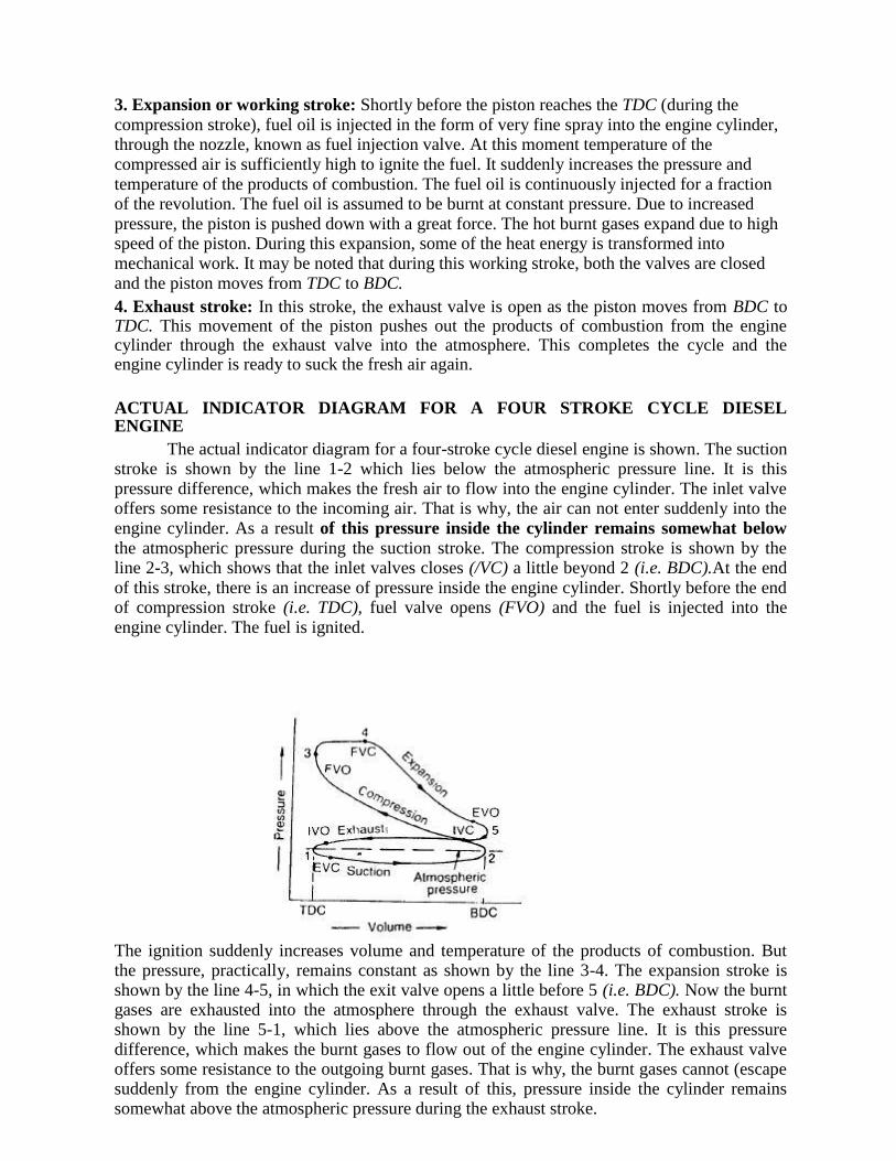
ACTUAL INDICATOR DIAGRAM FOR A FOUR STROKE CYCLE DIESEL ENGINE
The actual indicator diagram for a four-stroke cycle diesel engine is shown. The suction stroke is shown by the line 1-2 which lies below the atmospheric pressure line. It is this pressure difference, which makes the fresh air to flow into the engine cylinder. The inlet valve offers some resistance to the incoming air. That is why, the air can not enter suddenly into the engine cylinder. As a result of this pressure inside the cylinder remains somewhat below the atmospheric pressure during the suction stroke. The compression stroke is shown by the line 2-3, which shows that the inlet valves closes (/VC) a little beyond 2 (i.e. BDC).At the end of this stroke, there is an increase of pressure inside the engine cylinder. Shortly before the end of compression stroke (i.e. TDC), fuel valve opens (FVO) and the fuel is injected into the engine cylinder. The fuel is ignited.
The ignition suddenly increases volume and temperature of the products of combustion. But the pressure, practically, remains constant as shown by the line 3-4. The expansion stroke is shown by the line 4-5, in which the exit valve opens a little before 5 (i.e. BDC). Now the burnt gases are exhausted into the atmosphere through the exhaust valve. The exhaust stroke is shown by the line 5-1, which lies above the atmospheric pressure line. It is this pressure difference, which makes the burnt gases to flow out of the engine cylinder. The exhaust valve offers some resistance to the outgoing burnt gases. That is why, the burnt gases cannot (escape suddenly from the engine cylinder. As a result of this, pressure inside the cylinder remains somewhat above the atmospheric pressure during the exhaust stroke.
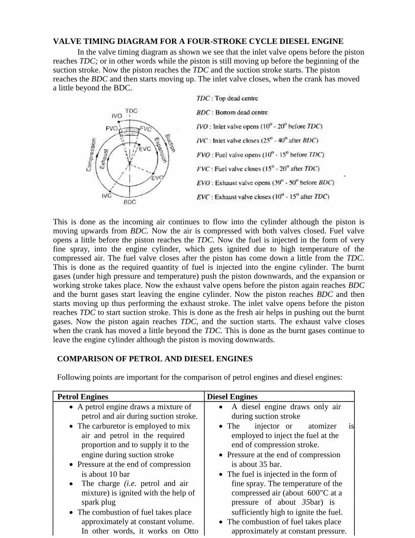
VALVE TIMING DIAGRAM FOR A FOUR-STROKE CYCLE DIESEL ENGINE In the valve timing diagram as shown we see that the inlet valve opens before the piston
reaches TDC; or in other words while the piston is still moving up before the beginning of the suction stroke. Now the piston reaches the TDC and the suction stroke starts. The piston reaches the BDC and then starts moving up. The inlet valve closes, when the crank has moved a little beyond the BDC. This is done as the incoming air continues to flow into the cylinder although the piston is moving upwards from BDC. Now the air is compressed with both valves closed. Fuel valve opens a little before the piston reaches the TDC. Now the fuel is injected in the form of very fine spray, into the engine cylinder, which gets ignited due to high temperature of the compressed air. The fuel valve closes after the piston has come down a little from the TDC. This is done as the required quantity of fuel is injected into the engine cylinder. The burnt gases (under high pressure and temperature) push the piston downwards, and the expansion or working stroke takes place. Now the exhaust valve opens before the piston again reaches BDC and the burnt gases start leaving the engine cylinder. Now the piston reaches BDC and then starts moving up thus performing the exhaust stroke. The inlet valve opens before the piston reaches TDC to start suction stroke. This is done as the fresh air helps in pushing out the burnt gases. Now the piston again reaches TDC, and the suction starts. The exhaust valve closes when the crank has moved a little beyond the TDC. This is done as the burnt gases continue to leave the engine cylinder although the piston is moving downwards.
COMPARISON OF PETROL AND DIESEL ENGINES Following points are important for the comparison of petrol engines and diesel engines:
Petrol Engines Diesel Engines
A petrol engine draws a mixture of A diesel engine draws only air
petrol and air during suction stroke. during suction stroke
The carburetor is employed to mix The injector or atomizer is
air and petrol in the required employed to inject the fuel at the proportion and to supply it to the end of compression stroke.
engine during suction stroke Pressure at the end of compression
Pressure at the end of compression is about 35 bar.
is about 10 bar The fuel is injected in the form of
The charge (i.e. petrol and air fine spray. The temperature of the
mixture) is ignited with the help of compressed air (about 600"C at a spark plug pressure of about 35bar) is
The combustion of fuel takes place sufficiently high to ignite the fuel.
approximately at constant volume. The combustion of fuel takes place In other words, it works on Otto approximately at constant pressure.
cycle In other words. It works on Diesel
A petrol engine has compression cycle.
ratio approximately from 6 to 10. A diesel engine has compression
The starting' is easy due to low ratio approximately from 15 to 25. compression ratio. The starting is little difficult due. to
As the compression ratio is low, the high compression ratio.
petrol engines are lighter and As the compression ratio is high.
cheaper. the diesel engine;; are heavier and
The running cost of a petrol engine costlier.
is high because of the higher cost of The running cost of diesel engine is
petrol. low because of the lower cost of
The maintenance cost is less. diesel.
The thermal efficiency is up to The maintenance cost is more.
about 26%. The thermal efficiency is up to
Overheating trouble is more due to about 40%
low thermal efficiency. Overheating trouble is less due to
These are high speed engines. high thermal efficiency
The petrol engines arc generally These are relatively low speed
employed in light duty vehicles engines.
such as scooters, motorcycles, cars. The diesel engines are generally
These are also used in aero planes employed in heavy duty vehicles
like buses. trucks, and earth moving . TWO-STROKE CYCLE PETROL ENGINE
A two-stroke cycle petrol engine was devised by Duglad Clerk in I RHO. In this cycle,
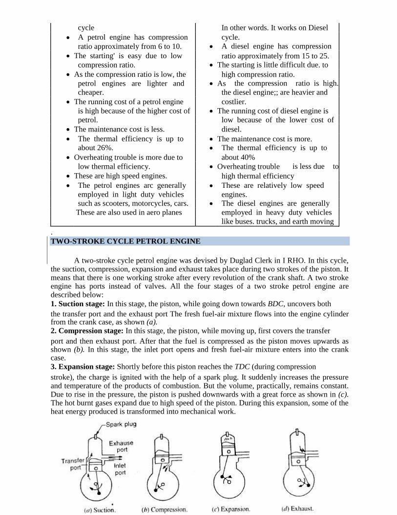
the suction, compression, expansion and exhaust takes place during two strokes of the piston. It means that there is one working stroke after every revolution of the crank shaft. A two stroke engine has ports instead of valves. All the four stages of a two stroke petrol engine are described below: 1. Suction stage: In this stage, the piston, while going down towards BDC, uncovers both the transfer port and the exhaust port The fresh fuel-air mixture flows into the engine cylinder from the crank case, as shown (a). 2. Compression stage: In this stage, the piston, while moving up, first covers the transfer port and then exhaust port. After that the fuel is compressed as the piston moves upwards as shown (b). In this stage, the inlet port opens and fresh fuel-air mixture enters into the crank case. 3. Expansion stage: Shortly before this piston reaches the TDC (during compression stroke), the charge is ignited with the help of a spark plug. It suddenly increases the pressure and temperature of the products of combustion. But the volume, practically, remains constant. Due to rise in the pressure, the piston is pushed downwards with a great force as shown in (c). The hot burnt gases expand due to high speed of the piston. During this expansion, some of the heat energy produced is transformed into mechanical work.
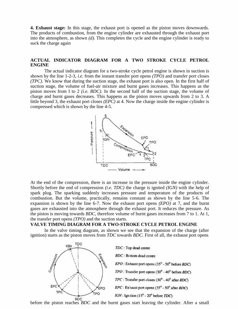
4. Exhaust stage: In this stage, the exhaust port is opened as the piston moves downwards. The products of combustion, from the engine cylinder are exhausted through the exhaust port into the atmosphere, as shown (d). This completes the cycle and the engine cylinder is ready to suck the charge again ACTUAL INDICATOR DIAGRAM FOR A TWO STROKE CYCLE PETROL ENGINE
The actual indicator diagram for a two-stroke cycle petrol engine is shown in suction is shown by the line 1-2-3, i.e. from the instant transfer port opens (TPO) and transfer port closes (TPC). We know that during the suction stage, the exhaust port is also open. In the first half of suction stage, the volume of fuel-air mixture and burnt gases increases. This happens as the piston moves from I to 2 (i.e. BDC). In the second half of the suction stage, the volume of charge and burnt gases decreases. This happens as the piston moves upwards from 2 to 3. A little beyond 3, the exhaust port closes (EPC) at 4. Now the charge inside the engine cylinder is compressed which is shown by the line 4-5. At the end of the compression, there is an increase in the pressure inside the engine cylinder. Shortly before the end of compression (i.e. TDC) the charge is ignited (IGN) with the help of spark plug. The sparking suddenly increases pressure and temperature of the products of combustion. But the volume, practically, remains constant as shown by the line 5-6. The expansion is shown by the line 6-7. Now the exhaust port opens (EPO) at 7, and the burnt gases are exhausted into the atmosphere through the exhaust port. It reduces the pressure. As the piston is moving towards BDC, therefore volume of burnt gases increases from 7 to 1. At 1, the transfer port opens (TPO) and the suction starts.
VALVE TIMING DIAGRAM FOR A TWO-STROKE CYCLE PETROL ENGINE In the valve timing diagram, as shown we see that the expansion of the charge (after
ignition) starts as the piston moves from TDC towards BDC. First of all, the exhaust port opens before the piston reaches BDC and the burnt gases start leaving the cylinder. After a small
fraction of the crank revolution, the transfer port also opens and the fresh fuel-air mixture enters into the engine cylinder. This is done as the fresh incoming charge helps in pushing out the burnt gases. Now the piston reaches BDC and then starts moving upwards. As the crank moves a little beyond BDC, first the transfer port closes and then the exhaust port also closes. This is done to suck fresh charge through the transfer port and to exhaust the burnt gases through the exhaust port simultaneously. Now the charge is compressed with both ports closed, and then ignited with the help of a spark plug before the end of compression stroke. This is done as the charge requires some time to ignite. By the time the piston reaches TDC, the burnt gases (under high pressure and temperature) push the piston downwards with full force and expansion of the burnt gases takes place. It may be noted that the exhaust and transfer ports open and close at equal angles on either side of the BDC position.
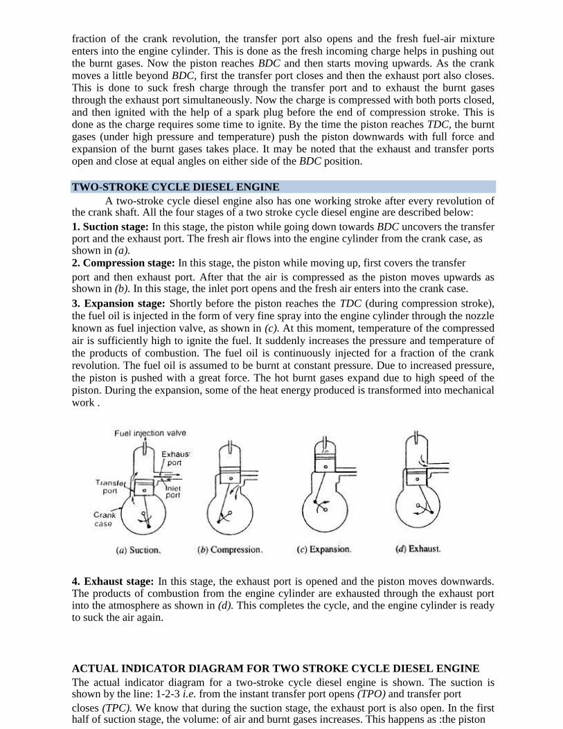
TWO-STROKE CYCLE DIESEL ENGINE A two-stroke cycle diesel engine also has one working stroke after every revolution of
the crank shaft. All the four stages of a two stroke cycle diesel engine are described below: 1. Suction stage: In this stage, the piston while going down towards BDC uncovers the transfer port and the exhaust port. The fresh air flows into the engine cylinder from the crank case, as shown in (a). 2. Compression stage: In this stage, the piston while moving up, first covers the transfer port and then exhaust port. After that the air is compressed as the piston moves upwards as shown in (b). In this stage, the inlet port opens and the fresh air enters into the crank case. 3. Expansion stage: Shortly before the piston reaches the TDC (during compression stroke), the fuel oil is injected in the form of very fine spray into the engine cylinder through the nozzle known as fuel injection valve, as shown in (c). At this moment, temperature of the compressed air is sufficiently high to ignite the fuel. It suddenly increases the pressure and temperature of the products of combustion. The fuel oil is continuously injected for a fraction of the crank revolution. The fuel oil is assumed to be burnt at constant pressure. Due to increased pressure, the piston is pushed with a great force. The hot burnt gases expand due to high speed of the piston. During the expansion, some of the heat energy produced is transformed into mechanical work . 4. Exhaust stage: In this stage, the exhaust port is opened and the piston moves downwards. The products of combustion from the engine cylinder are exhausted through the exhaust port into the atmosphere as shown in (d). This completes the cycle, and the engine cylinder is ready to suck the air again. ACTUAL INDICATOR DIAGRAM FOR TWO STROKE CYCLE DIESEL ENGINE The actual indicator diagram for a two-stroke cycle diesel engine is shown. The suction is shown by the line: 1-2-3 i.e. from the instant transfer port opens (TPO) and transfer port closes (TPC). We know that during the suction stage, the exhaust port is also open. In the first half of suction stage, the volume: of air and burnt gases increases. This happens as :the piston
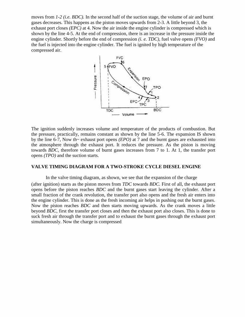
moves from 1-2 (i.e. BDC). In the second half of the suction stage, the volume of air and burnt
gases decreases. This happens as the piston moves upwards from 2-3. A little beyond 3, the
exhaust port closes (EPC) at 4. Now the air inside the engine cylinder is compressed which is
shown by the line 4-5. At the end of compression, there is an increase in the pressure inside the
engine cylinder. Shortly before the end of compression (i. e. TDC), fuel valve opens (FVO) and
the fuel is injected into the engine cylinder. The fuel is ignited by high temperature of the
compressed air. The ignition suddenly increases volume and temperature of the products of combustion. But the pressure, practically, remains constant as shown by the line 5-6. The expansion IS shown by the line 6-7, Now th~ exhaust port opens (EPO) at 7 and the burnt gases are exhausted into the atmosphere through the exhaust port. It reduces the pressure. As the piston is moving towards BDC, therefore volume of burnt gases increases from 7 to 1. At 1, the transfer port opens (TPO) and the suction starts.
VALVE TIMING DIAGRAM FOR A TWO-STROKE CYCLE DIESEL ENGINE
In the valve timing diagram, as shown, we see that the expansion of the charge (after ignition) starts as the piston moves from TDC towards BDC. First of all, the exhaust port opens before the piston reaches BDC and the burnt gases start leaving the cylinder. After a small fraction of the crank revolution, the transfer port also opens and the fresh air enters into the engine cylinder. This is done as the fresh incoming air helps in pushing out the burnt gases. Now the piston reaches BDC and then starts moving upwards. As the crank moves a little beyond BDC, first the transfer port closes and then the exhaust port also closes. This is done to suck fresh air through the transfer port and to exhaust the burnt gases through the exhaust port simultaneously. Now the charge is compressed
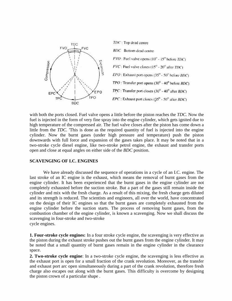
with both the ports closed. Fuel valve opens a little before the piston reaches the TDC. Now the fuel is injected in the form of very fine spray into the engine cylinder, which gets ignited due to high temperature of the compressed air. The fuel valve closes after the piston has come down a little from the TDC. 'This is done as the required quantity of fuel is injected into the engine cylinder. Now the burnt gases (under high pressure and temperature) push the piston downwards with full force and expansion of the gases takes place. It may be noted that in a two-stroke cycle diesel engine, like two-stroke petrol engine, the exhaust and transfer ports open and close at equal angles on either side of the BDC position.
SCAVENGING OF I.C. ENGINES
We have already discussed the sequence of operations in a cycle of an I.C. engine. The last stroke of an IC engine is the exhaust, which means the removal of burnt gases from the engine cylinder. It has been experienced that the burnt gases in the engine cylinder are not completely exhausted before the suction stroke. But a part of the gases still remain inside the cylinder and mix with the fresh charge. As a result of this mixing, the fresh charge gets diluted and its strength is reduced. The scientists and engineers, all over the world, have concentrated on the design of their IC engines so that the burnt gases are completely exhausted from the engine cylinder before the suction starts. The process of removing burnt gases, from the combustion chamber of the engine cylinder, is known a scavenging. Now we shall discuss the scavenging in four-stroke and two-stroke cycle engines.
1. Four-stroke cycle engines: In a four stroke cycle engine, the scavenging is very effective as the piston during the exhaust stroke pushes out the burnt gases from the engine cylinder. It may be noted that a small quantity of burnt gases remain in the engine cylinder in the clearance space. 2. Two-stroke cycle engine: In a two-stroke cycle engine, the scavenging is less effective as the exhaust port is open for a small fraction of the crank revolution. Moreover, as the transfer and exhaust port arc open simultaneously during a part of the crank revolution, therefore fresh charge also escapes out along with the burnt gases. This difficulty is overcome by designing the piston crown of a particular shape .
TYPES OF SCAVENGING
Though there are many types of scavenging, yet the following are important from the
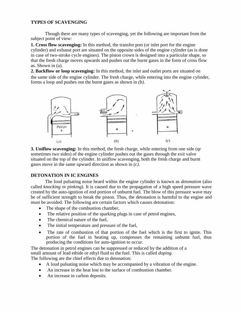
subject point of view: 1. Cross flow scavenging: In this method, the transfer port (or inlet port for the engine cylinder) and exhaust port are situated on the opposite sides of the engine cylinder (as is done in case of two-stroke cycle engines). The piston crown is designed into a particular shape, so that the fresh charge moves upwards and pushes out the burnt gases in the form of cross flow as. Shown in (a). 2. Backflow or loop scavenging: In this method, the inlet and outlet ports are situated on the same side of the engine cylinder. The fresh charge, while entering into the engine cylinder, forms a loop and pushes out the burnt gases as shown in (b).
3. Uniflow scavenging: In this method, the fresh charge, while entering from one side (qr sometimes two sides) of the engine cylinder pushes out the gases through the exit valve situated on the top of the cylinder. In uniflow scavenging, both the fresh charge and burnt gases move in the same upward direction as shown in (c).
DETONATION IN IC ENGINES The loud pulsating noise heard within the engine cylinder is known as detonation (also
called knocking or pinking). It is caused due to the propagation of a high speed pressure wave created by the auto-ignition of end portion of unburnt fuel. The blow of this pressure wave may be of sufficient strength to break the piston. Thus, the detonation is harmful to the engine and must be avoided. The following are certain factors which causes detonation:
The shape of the combustion chamber,
The relative position of the sparking plugs in case of petrol engines,
The chemical nature of the fuel,
The initial temperature and pressure of the fuel,
The rate of combustion of that portion of the fuel which is the first to ignite. This portion of the fuel in heating up, compresses the remaining unbumt fuel, thus producing the conditions for auto-ignition to occur.
The detonation in petrol engines can be suppressed or reduced by the addition of a small amount of lead ethide or ethyl fluid to the fuel. This is called doping. The following are the chief effects due to detonation:
A loud pulsating noise which may be accompanied by a vibration of the engine. An increase in the heat lost to the surface of combustion chamber.
An increase in carbon deposits.
RATING OF SI ENGINE FUELS OCTANE NUMBER
The hydrocarbon fuels used in spark ignition (S.I.) engine have a tendency to cause
engine knock when the engine operating conditions become severe. The knocking tendency of
a fuel in S.I. engines is generally expressed by its octane number. The percentage, by volume, of iso-octane in a mixture of iso-octane normal heptane ,which exactly matches the knocking
intensity of a given fuel, in a standard engine, under given standard operating conditions, is termed as the octane number rating of that fuel. Thus, if a mixture of 50 percent iso-octane and
50 percent normal heptane matches the fuel under test, then this fuel is assigned an octane number rating of 50. If a fuel matches in knocking intensity a mixture of 75 percent iso-octane
and 25 percent normal heptane, then this fuel would be assigned an octane number rating of 75. This octane number rating is an expression which indicates the ability of a fuel to resist knock
in a S.1. engine. Since iso-octane is a very good anti-knock fuel, therefore it is assigned a rating of 100 octane number. On the other hand, normal heptane has very poor anti-knock
qualities, therefore it is given a rating of 0 (zero) octane number. These two fuels, i.e. iso-
octane and normal heptane are known as primary reference fuels. It may be noted that higher the octane number rating of a fuel, the greater will be its resistance to knock and the higher will
be the· compression ratio. Since the power output and specific fuel consumption are functions of compression ratio, therefore we may say that these are also functions of octane number
rating. This fact indicates the extreme importance of the octane number rating in fuels for S.I. engines.
RATING OF CI ENGINE FUELS CETANE NUMBER
The knocking tendency is also found in compression ignition (C.I.) engines with an effect similar to that of S.1. engines, but it is due to a different phenomenon. The knock in C.I. engines is due to sudden ignition and abnormally rapid combustion of accumulated fuel in the combustion chamber Such a situation occurs Because of an Ignition lag in the combustion of the fuel between the time of injection and the actual burning. The property of ignition lag is generally measured in terms of cetane number. It is defined as the percentage, by volume, of cetane in a mixture of cetane and alpha-methyl-naphthalene that produces the same ignition lag as the fuel being tested in the same engine and under the same operating conditions. For example, a fuel of cetane number 50 has the same ignition quality as a mixture of 50 percent cetane and 50 percent alpha-methyl-naphthalene. The cetane which is a straight chain paraffin with good ignition quality is assigned a cetane number of 100 and alpha-methyl-naphthalene which is a hydrocarbon with poor ignition quality, is assigned a 0 (zero) cetane number.
IGNITION SYSTEMS OF PETROL ENGINES
We have already discussed that the ignition in a petrol engine, takes place by means of a spark plug at the end of the compression stroke. The voltage required to produce a spark across the gap between the sparking points of a plug, is about 8000 volts. Thus, the ignition system in a petrol engine has to transform the normal battery voltage (6 to 12 volts) to 8000 volts. In addition to this, the ignition system has to provide spark in each cylinder at the appropriate time. Following two ignition systems of petrol engines are important from the subject point of view: 1. Coil ignition system 2. Magneto ignition system.
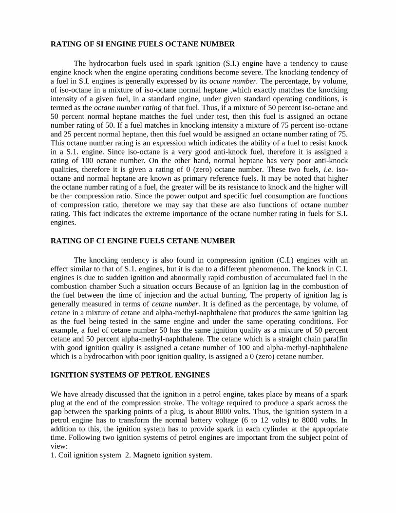
COIL IGNITION SYSTEM
It is also known as battery ignition system, and has an induction coil, which consists of two coils known as primary and secondary coils wound on a soft iron core, as shown . The primary coil consists of a few hundred turns (about 300 turns) of wire. Over this coil, but insulated from it, are wound several thousand turns (about 20,000 turns) of secondary coil. The one end of the primary coil is connected to a ignition switch, ammeter and battery generally of 6 volts. The other end of the primary coil is connected to a condenser and a contact breaker.
A condenser is connected across the contact-breaker for the following two reasons: It prevents sparking across the gap between the points,
It causes a more rapid break of the primary current, giving a higher voltage in the
secondary circuit. The secondary coil is connected to a distributor (in a multi-cylinder engine) with the central
terminal of the sparking plugs. The outer terminals of the sparking plugs are earthed together,
and connected to the body of the engine. When the current flows through the primary coil, it sets up a magnetic field which surrounds both the primary and secondary coils. As the switch is
on, the contact-breaker connects the two ends. The magnetic field in coils has tendency to grow from zero to maximum value. Due to this change in the magnetic field, a voltage is generated
in both the coils, but opposite to the applied voltage (of battery). Thus the primary coil does not give the final value. The voltage in the secondary coil is, therefore, not sufficient to overcome
the resistance of the air gap of the sparking plug, hence no spark occurs. When the current in the primary coil is switched off by the moving cam, the magnetic field generated around the
coil collapses immediately. The sudden variation of flux, which takes place, gives rise to the
voltage generated in each coil. The value of the voltage depends upon the number of turns in each coil. As a matter of fact, the voltage required to produce a spark across the gap, between
the sparking points, is between 10 000 to 20 000 volts. Since the secondary coil has several thousand turns, so it develops a sufficient high voltage to overcome the resistance of the gap of
the sparking plug. This high voltage then passes to a distributor. It connects the sparking plugs in rotation depending upon the firing order of the engine. Hence, the ignition of fuel takes
place in all the engine cylinders. The coil ignition system is employed in medium and heavy spark ignition engines such as in cars. MAGNETO IGNITION SYSTEM
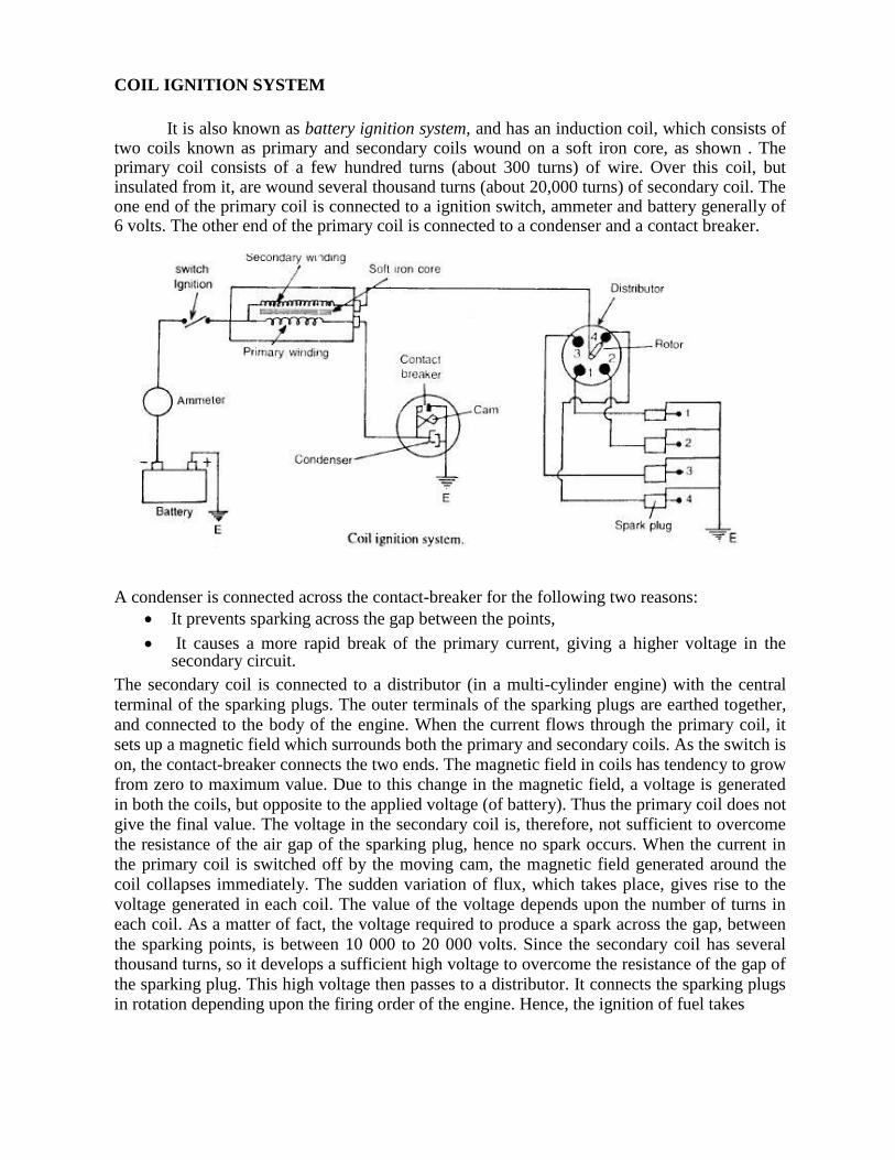
The magneto ignition system as shown has the same principle of working as that of coil ignition system; except that no battery is required as the magneto acts its own generator. It consists of either rotating magnets in fixed coils, or rotating coils in fixed magnets. The current produced by the magneto is made to flow to the induction coil which works in the same way as that of coil ignition system. The high voltage current is then made to flow to the distributor, which connects the sparking plugs in rotation depending upon the firing order of the engine. This type of ignition system is generally employed in small spark ignition engines such as scooters, motor cycles and small motor boat engines. FUEL INJECTION SYSTEM FOR DIESEL ENGINES
The fol1owing two methods of fuel injection system are generally employed with diesel
engines (i.e.compression ignition engines) : 1. Air injection method, and 2. Airless or solid injection method.
These methods are discussed, in detail, as follows: 1. Air injection method: In this method of fuel injection, a blast of compressed air is used to inject the fuel into the engine cylinder. This method requires the aid of an air compressor which is driven by the engine crankshaft. The air is compressed at a pressure higher than that of engine cylinder at the end of its compression stroke. This method is not used now-a-days because of complicated and expensive system. 2. Airless or solid injection method: The most modern compression ignition engines use, now-a-days, the solid injection system. In this method, a separate fuel pump driven by the main crankshaft is used for forcing the fuel. The fuel is compressed in this pump to a pressure higher than that of engine cylinder at the end of compression. This fuel under pressure is directly sprayed into the combustion chamber of the engine cylinder at the end of compression stroke,
with the help of an injector. The solid injection method may be further divided into the following two commonly used systems.
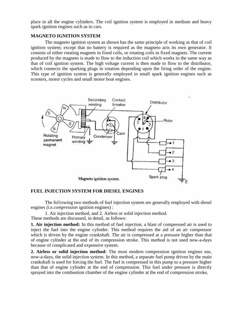
Common rail system
Individual pump system Common rail system: In the common rail system as shown a multi cylinder high pressure pump is used to supply the fuel at a high pressure to a common rail or header.
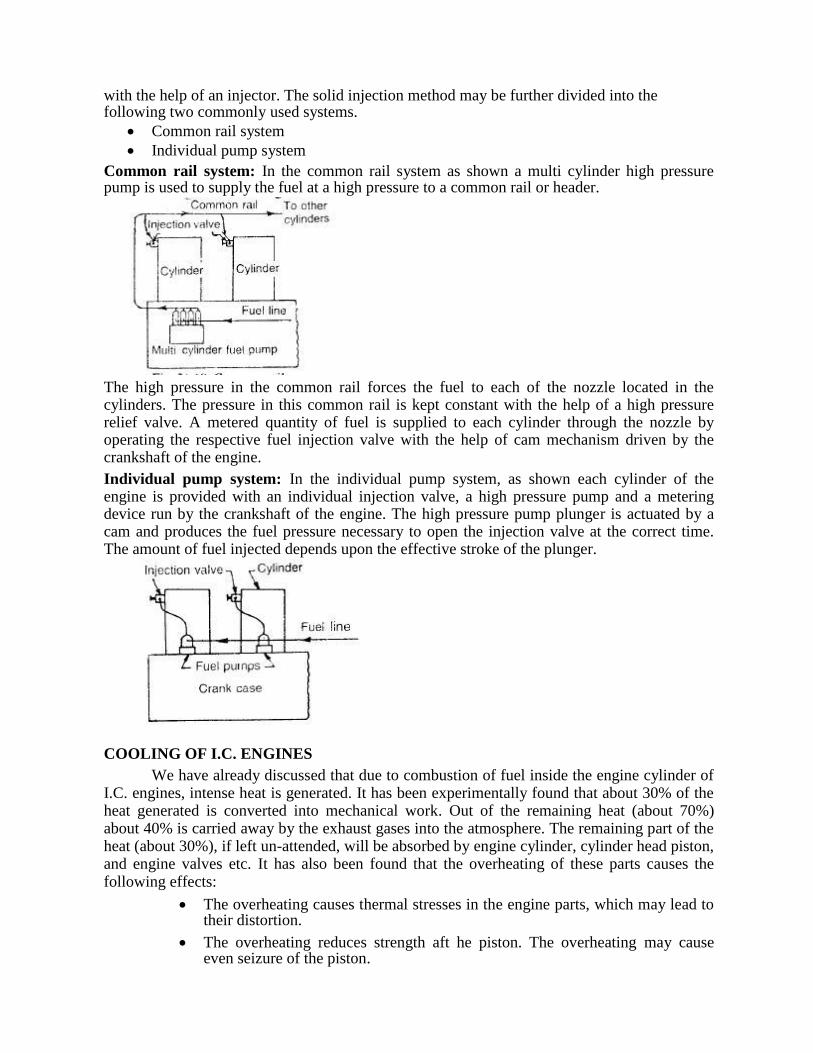
The high pressure in the common rail forces the fuel to each of the nozzle located in the cylinders. The pressure in this common rail is kept constant with the help of a high pressure relief valve. A metered quantity of fuel is supplied to each cylinder through the nozzle by operating the respective fuel injection valve with the help of cam mechanism driven by the crankshaft of the engine. Individual pump system: In the individual pump system, as shown each cylinder of the engine is provided with an individual injection valve, a high pressure pump and a metering device run by the crankshaft of the engine. The high pressure pump plunger is actuated by a cam and produces the fuel pressure necessary to open the injection valve at the correct time. The amount of fuel injected depends upon the effective stroke of the plunger. COOLING OF I.C. ENGINES
We have already discussed that due to combustion of fuel inside the engine cylinder of I.C. engines, intense heat is generated. It has been experimentally found that about 30% of the heat generated is converted into mechanical work. Out of the remaining heat (about 70%) about 40% is carried away by the exhaust gases into the atmosphere. The remaining part of the heat (about 30%), if left un-attended, will be absorbed by engine cylinder, cylinder head piston, and engine valves etc. It has also been found that the overheating of these parts causes the following effects:
The overheating causes thermal stresses in the engine parts, which may lead to their distortion.
The overheating reduces strength aft he piston. The overheating may cause
even seizure of the piston.
The overheating causes decomposition of the lubricating oil, which may cause carbon deposit on the engine and piston head.
The over heating, causes burning of valves and valve seats.
The overheating reduces volumetric efficiency of the engine.
The overheating increases tendency of the detonation . In other to avoid the adverse effects of overheating, it is very essential to provide some
cooling system for an I.C. engine. In general, the cooling system provided should have the following two characteristics for its efficient working:
It should be capable of removing about 30% of that total heat generated in the combustion chamber. It has been experienced that removal of more than 30% of heat generated reduces thermal efficiency of the engine. Similarly, removal of less than 30% of the heat generated will have some adverse effects as mentioned above.
It should be capable of removing heat at a fast rate, when the engine is hot. But at the
time of starting the engine, the cooling should be comparatively slow, so that the various components of the engine attain their working temperature in a short time.
COOLING SYSTEMS FOR I.C. ENGINES We have already discussed, in the last article, the adverse effects of overheating of an
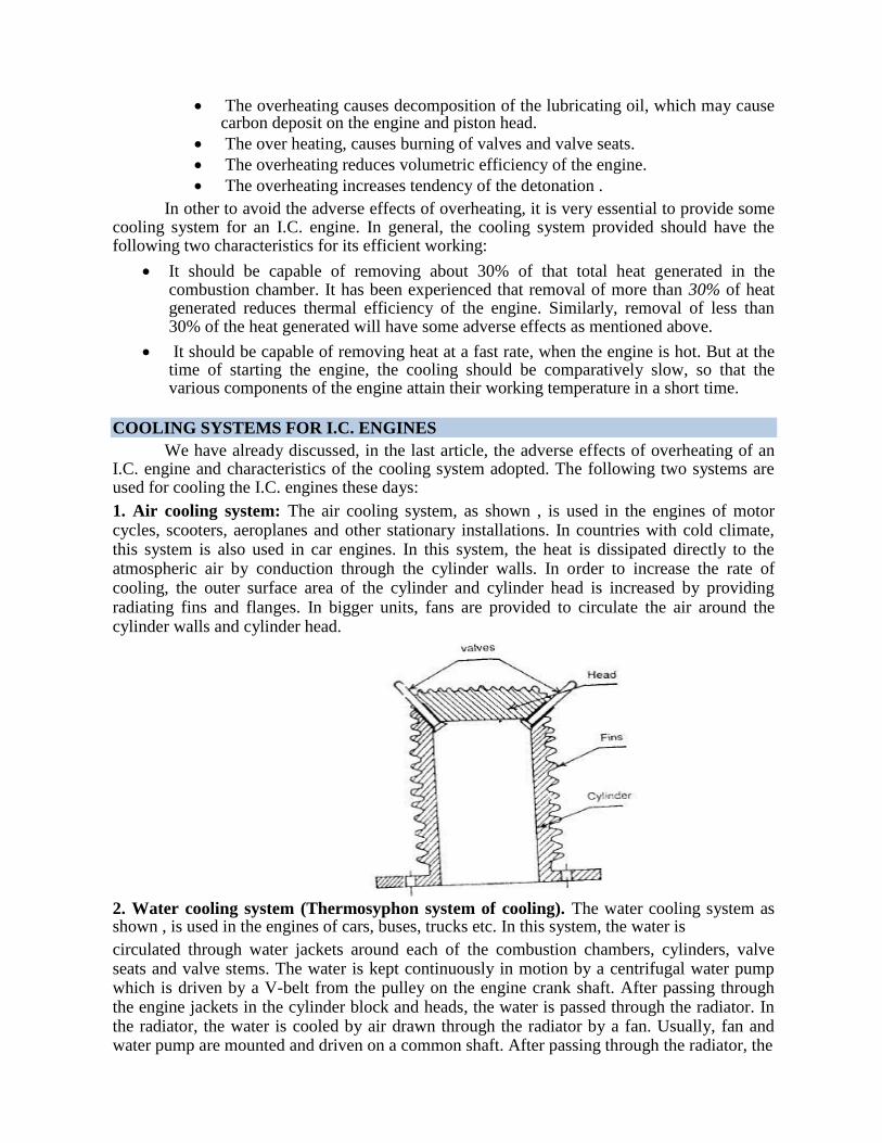
I.C. engine and characteristics of the cooling system adopted. The following two systems are used for cooling the I.C. engines these days: 1. Air cooling system: The air cooling system, as shown , is used in the engines of motor cycles, scooters, aeroplanes and other stationary installations. In countries with cold climate, this system is also used in car engines. In this system, the heat is dissipated directly to the atmospheric air by conduction through the cylinder walls. In order to increase the rate of cooling, the outer surface area of the cylinder and cylinder head is increased by providing radiating fins and flanges. In bigger units, fans are provided to circulate the air around the cylinder walls and cylinder head. 2. Water cooling system (Thermosyphon system of cooling). The water cooling system as shown , is used in the engines of cars, buses, trucks etc. In this system, the water is circulated through water jackets around each of the combustion chambers, cylinders, valve seats and valve stems. The water is kept continuously in motion by a centrifugal water pump which is driven by a V-belt from the pulley on the engine crank shaft. After passing through the engine jackets in the cylinder block and heads, the water is passed through the radiator. In the radiator, the water is cooled by air drawn through the radiator by a fan. Usually, fan and water pump are mounted and driven on a common shaft. After passing through the radiator, the
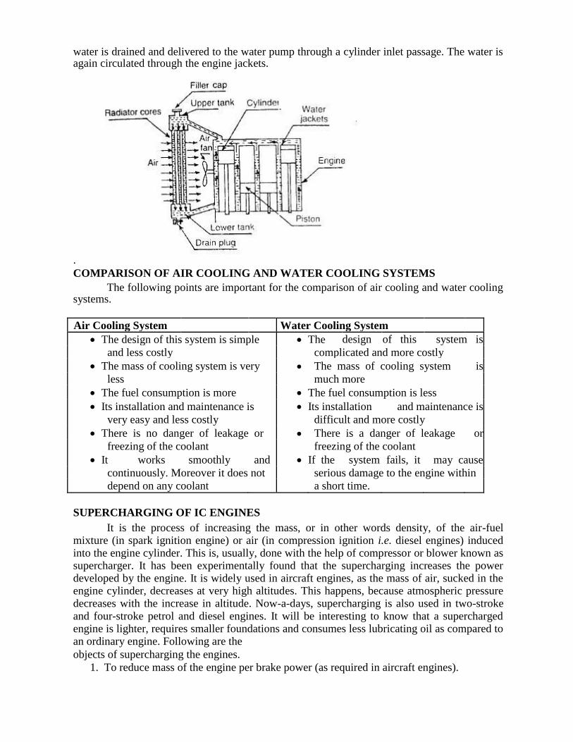
water is drained and delivered to the water pump through a cylinder inlet passage. The water is again circulated through the engine jackets.
. COMPARISON OF AIR COOLING AND WATER COOLING SYSTEMS
The following points are important for the comparison of air cooling and water cooling systems.
Air Cooling System Water Cooling System
The design of this system is simple The design of this system is
and less costly complicated and more costly
The mass of cooling system is very The mass of cooling system is
less much more
The fuel consumption is more The fuel consumption is less
Its installation and maintenance is Its installation and maintenance is
very easy and less costly difficult and more costly
There is no danger of leakage or There is a danger of leakage or
freezing of the coolant freezing of the coolant
It works smoothly and If the system fails, it may cause
continuously. Moreover it does not serious damage to the engine within
depend on any coolant a short time.
SUPERCHARGING OF IC ENGINES It is the process of increasing the mass, or in other words density, of the air-fuel
mixture (in spark ignition engine) or air (in compression ignition i.e. diesel engines) induced into the engine cylinder. This is, usually, done with the help of compressor or blower known as supercharger. It has been experimentally found that the supercharging increases the power developed by the engine. It is widely used in aircraft engines, as the mass of air, sucked in the engine cylinder, decreases at very high altitudes. This happens, because atmospheric pressure decreases with the increase in altitude. Now-a-days, supercharging is also used in two-stroke and four-stroke petrol and diesel engines. It will be interesting to know that a supercharged engine is lighter, requires smaller foundations and consumes less lubricating oil as compared to an ordinary engine. Following are the objects of supercharging the engines.
1. To reduce mass of the engine per brake power (as required in aircraft engines).
2. To maintain power of aircraft engines at high altitudes where less oxygen is available
for combustion. 3. To reduce space occupied by the engine (as required in marine engines).
4. To reduce the consumption of lubricating oil (as required in all type of engines). 5. To increase the power output of an engine when greater power is required (as required
in racing cars and other engines).
METHODS OF SUPERCHARGING Strictly speaking, a supercharger is an air pump, which receives air from the'
atmosphere surrounding the engine, compresses it to a higher pressure and then feeds it into the inlet valve of the engine.
Following two method; of supercharging are important from the subject point of view: 1. Reciprocating type: It has a piston which moves to and fro inside a cylinder. It is an old method and is not encouraged these days, as it occupies a large space and has lubrication problem. 2. Rotary type: It resembles a centrifugal pump i 1its outward appearance, but differs in action. There are many types of rotary pumps, but gear type, lobe type and vane type are commonly used.
LUBRICATION OF I.C. ENGINES As a matter of fact, the moving parts of an I.C engine are likely to wear off due to
continuous rubbing action of one part with another. In order to avoid an early wearing of the engine parts, a proper lubrication arrangement is provided in I.C. engines.
In general, following are the main advantages of lubrication of I.C. engines:
1. It reduces wear and tear of the moving parts.
2. It damps down the vibrations of the engine.
3. It dissipates the heat generated from the moving parts due to friction.
4. It cleans the moving parts.
5. It makes the piston gas-tight. LUBRICATION SYSTEM FOR IC ENGINES
The following two lubrication systems of I.C. engines are important from the subject
point of view:
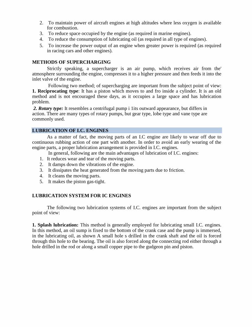
1. Splash lubrication: This method is generally employed for lubricating small I.C. engines. In this method, an oil sump is fixed to the bottom of the crank case and the pump is immersed, in the lubricating oil, as shown A small hole s drilled in the crank shaft and the oil is forced through this hole to the bearing. The oil is also forced along the connecting rod either through a hole drilled in the rod or along a small copper pipe to the gudgeon pin and piston.
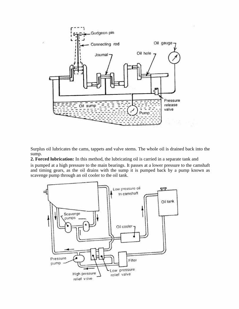
Surplus oil lubricates the cams, tappets and valve stems. The whole oil is drained back into the sump. 2. Forced lubrication: In this method, the lubricating oil is carried in a separate tank and is pumped at a high pressure to the main bearings. It passes at a lower pressure to the camshaft and timing gears, as the oil drains with the sump it is pumped back by a pump known as scavenge pump through an oil cooler to the oil tank.
GOVERNING OF I.C. ENGINES As a matter of fact, all the I.C. engines like other engines, are always designed to run at
a particular speed. But in actual practice, load on the engine keeps on fluctuating from time to time. A little consideration will show, that change of load, on an I.C. engine, is sure to change its speed. It has been observed that if load on an I.C. engine is decreased without changing the quantity of fuel, the engine will run at a higher speed. Similarly, if load on the engine is increased without changing the quantity of fuel, the engine will run at a lower speed. Now, in order to have a high efficiency of an I.C. engine, at different load conditions, its speed must be kept constant as far as possible. The process of providing any arrangement, which will keep the speed constant (according to the changing load conditions) is known as governing of I.C. engines.
METHODS OF GOVERNING I.C.ENGINES
Through there are many methods for the governing of I.C. engines, yet the following
are important from the subject point of view: I. Hit and miss governing: This method of governing is widely used for IC engines of smaller capacity or gas engines This method is most suitable for engines, which are frequently subjected to reduced loads and ,LS a result of this, the engines tend to run at higher speeds. In this system of governing, whenever the engine starts running at higher speed (due to decreased load), some explosion are omitted or missed. This is done with help of centrifugal governor in which the inlet valve of fuel is closed and the explosions are omitted till the engine speed reaches its normal value. The only disadvantage of this method is that there is uneven turning moment due to missing of explosions. As a result of this, it requires a heavy flywheel. . 2. Qualitative governing: In this system of governing, a control valve is fitted in the fuel delivery pipe, which controls the quantity of fuel to be mixed in the charge. The movement of control valve is regulated by the centrifugal governor through rack and pinion arrangement. It may be noted that in this system, the amount of air used in each cycle remains the same. But with the change in the quantity of fuel (with quantity of air remaining constant), the quality of charge (i. e. air-fuel ratio of mixture) changes. Whenever the engine starts running at higher speed (due to decreased load), the quantity of fuel is reduced till the engine speed reaches its normal value. Similarly, whenever the engine starts running at lower speed (due to increased load), the quantity of fuel is increased. In automobile engines, the rack and pinion arrangement is connected with the accelerator. 3. Quantitative governing: In this system of governing, the quality of charge (i.e. air-fuel ratio of the mixture) is kept constant. But quantity of mixture supplied to the engine cylinder is varied by means of a throttle valve which is regulated by the centrifugal governor through rack and pinion arrangement. Whenever the engine starts running at higher speed (cue to decreased load), the quantity of charge is reduced till the engine speed reaches its normal value. Similarly, whenever the engine starts running at lower speed (due to increased load), the quantity of charge is increased. This method is used for governing large engines. 4. Combination system of governing: In this system of governing, the above mentioned two methods of governing (i.e. qualitative and quantitative) are combined together, so that quality as well as quantity of the charge is varied according to the changing conditions. This system is complicated, and has not proved to be successful.
CARBURETTOR
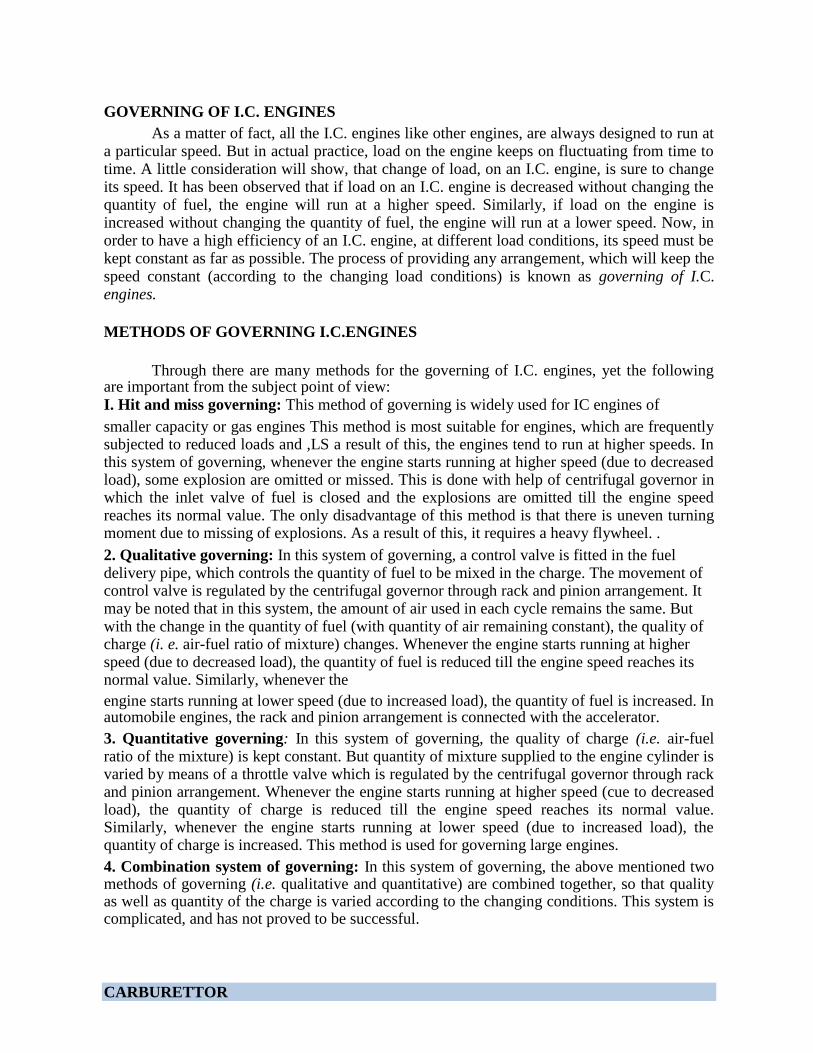
The carburettor is a device for atomising and vaporing the fuel and mixing it with the
air in the varying proportions to suit the changing operating conditions of the engine. The process of breaking up and mixing the fuel with the air is called carburation. There are many types of the carburettors in use, but the simplest form of the carburettor is shown. It consists of a fuel jet located in the centre of the choke tube. A float chamber is provided for maintaining the level of the fuel in the jet and is controlled by a float and lever which operates its needle valve. The fuel is pumped into the float chamber and when the correct level of the fuel is reached, the float closes the needle valve, and shuts off the petrol supply. The suction produced by the engine draws air through t:le choke tube. The reduced diameter of the choke tube increases the velocity of air and reduces the pressure. The high velocity and low pressure in the tube facilitates the breaking up of fuel and its admixture with the air. A throttle valve controls the flow of the mixture delivered to the engine cylinder.
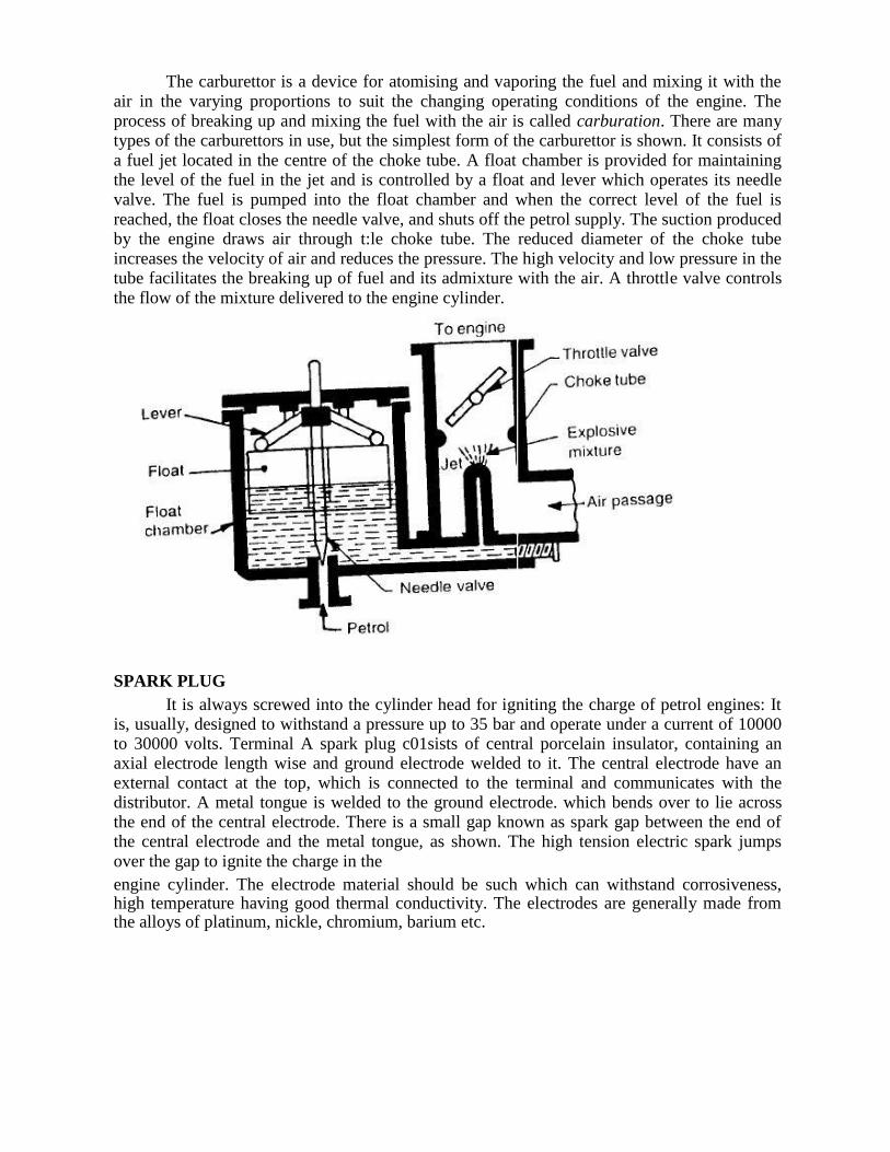
SPARK PLUG It is always screwed into the cylinder head for igniting the charge of petrol engines: It
is, usually, designed to withstand a pressure up to 35 bar and operate under a current of 10000 to 30000 volts. Terminal A spark plug c01sists of central porcelain insulator, containing an axial electrode length wise and ground electrode welded to it. The central electrode have an external contact at the top, which is connected to the terminal and communicates with the distributor. A metal tongue is welded to the ground electrode. which bends over to lie across the end of the central electrode. There is a small gap known as spark gap between the end of the central electrode and the metal tongue, as shown. The high tension electric spark jumps over the gap to ignite the charge in the engine cylinder. The electrode material should be such which can withstand corrosiveness, high temperature having good thermal conductivity. The electrodes are generally made from the alloys of platinum, nickle, chromium, barium etc.
FUEL PUMP
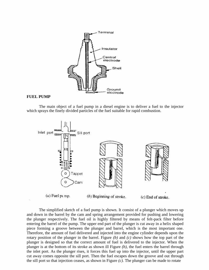
The main object of a fuel pump in a diesel engine is to deliver a fuel to the injector
which sprays the finely divided particles of the fuel suitable for rapid combustion.
The simplified sketch of a fuel pump is shown. It consist of a plunger which moves up and down in the barrel by the cam and spring arrangement provided for pushing and lowering the plunger respectively. The fuel oil is highly filtered by means of felt-pack filter before entering the barrel of the pump. The upper end part of the plunger is cut away in a helix shaped piece forming a groove between the plunger and barrel, which is the most important one. Therefore, the amount of fuel delivered and injected into the engine cylinder depends upon the rotary position of the plunger in the barrel. Figure (b) and (c) shows how the top part of the plunger is designed so that the correct amount of fuel is delivered to the injector. When the plunger is at the bottom of its stroke as shown ill Figure (b), the fuel enters the barrel through the inlet port. As the plunger rises, it forces this fuel up into the injector, until the upper part cut away comes opposite the sill port. Then the fuel escapes down the groove and out through the sill port so that injection ceases, as shown in Figure (c). The plunger can be made to rotate
in the barrel and therefore more fuel is injected. When the plunger is rotated so that the groove
is opposite to the sill port, no fuel at all is injected and thus the engine stops
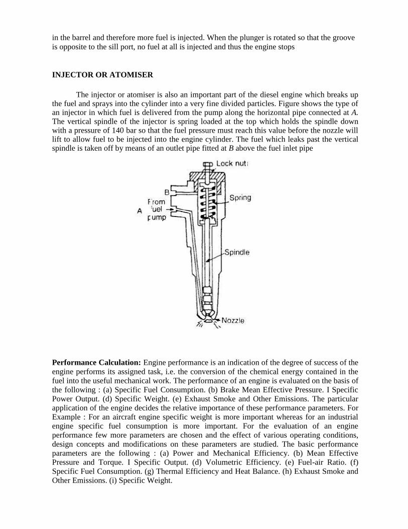
INJECTOR OR ATOMISER
The injector or atomiser is also an important part of the diesel engine which breaks up the fuel and sprays into the cylinder into a very fine divided particles. Figure shows the type of an injector in which fuel is delivered from the pump along the horizontal pipe connected at A. The vertical spindle of the injector is spring loaded at the top which holds the spindle down with a pressure of 140 bar so that the fuel pressure must reach this value before the nozzle will lift to allow fuel to be injected into the engine cylinder. The fuel which leaks past the vertical spindle is taken off by means of an outlet pipe fitted at B above the fuel inlet pipe
Performance Calculation: Engine performance is an indication of the degree of success of the
engine performs its assigned task, i.e. the conversion of the chemical energy contained in the fuel into the useful mechanical work. The performance of an engine is evaluated on the basis of the following : (a) Specific Fuel Consumption. (b) Brake Mean Effective Pressure. I Specific Power Output. (d) Specific Weight. (e) Exhaust Smoke and Other Emissions. The particular application of the engine decides the relative importance of these performance parameters. For Example : For an aircraft engine specific weight is more important whereas for an industrial engine specific fuel consumption is more important. For the evaluation of an engine performance few more parameters are chosen and the effect of various operating conditions, design concepts and modifications on these parameters are studied. The basic performance parameters are the following : (a) Power and Mechanical Efficiency. (b) Mean Effective Pressure and Torque. I Specific Output. (d) Volumetric Efficiency. (e) Fuel-air Ratio. (f) Specific Fuel Consumption. (g) Thermal Efficiency and Heat Balance. (h) Exhaust Smoke and Other Emissions. (i) Specific Weight.
Power and Mechanical Efficiency The main purpose of running an engine is to obtain
mechanical power. • Power is defined as the rate of doing work and is equal to the product of force and linear velocity or the product of torque and angular velocity. Thus, the measurement of power involves the measurement of force (or torque) as well as speed. The force or torque is measured with the help of a dynamometer and the speed by a tachometer. The power developed by an engine and measured at the output shaft is called the brake power (bp) and is given by
BP=2ΠNT/60
where, T is torque in N-m and N is the rotational speed in revolutions per minute. The total power developed by combustion of fuel in the combustion chamber is, however, more than the BP and is called indicated power (IP). Of the power developed by the engine, i.e. IP, some power is consumed in overcoming the friction between moving parts, some in the process of inducting the air and removing the products of combustion from the engine combustion chamber.
Indicated Power It is the power developed in the cylinder and thus, forms the basis of evaluation of combustion efficiency or the heat release in the cylinder.
I.P= PmLANK/60 Where,
Pm = Mean effective pressure, N/m2, L = Length of the stroke, m, A = Area of the piston, m
2,
N = Rotational speed of the engine, rpm (It is N/2 for four stroke engine), and k = Number of cylinders. Thus, we see that for a given engine the power output can be measured in terms of mean effective pressure. The difference between the IP and BP is the indication of the power lost in the mechanical components of the engine (due to friction) and forms the basis of mechanical efficiency; which is defined as follows:
Mechanical efficiency=BP/IP
The difference between ip and bp is called friction power (FP). FP = IP − Bp Mechanical efficiency= BP/(BP+FP)
Mean Effective Pressure and Torque Mean effective pressure is defined as a hypothetical/average pressure which is assumed to be acting on the piston throughout the power stroke. Therefore,
Pm=60XI.P/LANk
where, Pm = Mean effective pressure, N/m2, IP = Indicated power, Watt, L = Length of the
stroke, m, A = Area of the piston, m2, N = Rotational speed of the engine, rpm (It is N/2 for
four stroke engine), and k = Number of cylinders. If the mean effective pressure is based on BP it is called the brake mean effective pressure( Pm), and if based on IP it is called indicated mean effective pressure (imep). Similarly, the friction mean effective pressure (fmep) can be defined as,
fmep = imep – bmep
The torque is related to mean effective pressure by the relation
B.P=2ΠnT/60
I.P=PmLANk/60
2ΠnT/60=[bmep.A.L.(Nk/60)]
or, T=(bmep.A.L.k)/2π
Thus, the torque and the mean effective pressure are related by the engine size. A large engine produces more torque for the same mean effective pressure. For this reason, torque is not the measure of the ability of an engine to utilize its displacement for producing power from fuel. It is the mean effective pressure which gives an indication of engine displacement utilization for this conversion. Higher the mean effective pressure, higher will be the power developed by the engine for a given displacement. Again we see that the power of an engine is dependent on its size and speed. Therefore, it is not possible to compare engines on the basis of either power or torque. Mean effective pressure is the true indication of the relative performance of different engines.
Specific Output Specific output of an engine is defined as the brake power (output) per unit of piston displacement and is given by, Specific output=B.P/A.L
Constant = bmep × rpm •
The specific output consists of two elements – the bmep (force) available to work and the speed with which it is working. • Therefore, for the same piston displacement and bmep an engine operating at higher speed will give more output. It is clear that the output of an engine can be increased by increasing either speed or bmep. Increasing speed involves increase in the mechanical stress of various engine parts whereas increasing bmep requires better heat release and more load on engine cylinder.
Fuel-Air Ratio (F/A) Fuel-air ratio (F/A) is the ratio of the mass of fuel to the mass of air in
the fuel-air mixture. Air-fuel ratio (A/F) is reciprocal of fuel-air ratio. Fuel-air ratio of the mixture affects the combustion phenomenon in that it determines the flame propagation velocity, the heat release in the combustion chamber, the maximum temperature and the completeness of combustion. Relative fuel-air ratio is defined as the ratio of the actual fuel-air ratio to that of the stoichiometric fuel-air ratio required to burn the fuel supplied. Stoichiometric fuel-air ratio is the ratio of fuel to air is one in which case fuel is completely burned due to minimum quantity of air supplied.
Relative fuel-air ratio, =(Actual Fuel- Air ratio)/(Stoichiometric fuel-Air ratio)
Indicated Specific Fuel Consumption: This is defined as the mass of fuel consumption per hour in order to produce an indicated power of one kilo watt.
Brake Specific fuel consumption:- This defined as the mass of fuel consumed per hour,in order to develop a brake power of one kilowatt.
Thermal Efficiency : There are two definitions of thermal efficiency as applied to IC engines. One is based on indicated power and the other on brake power.The one based on indicated power is called as „indicated thermal efficiency”, and the one based on brake power is known as “brake thermal efficiency”. Indicated thermal efficiency is
defined as the ratio of indicated power to the energy available due to combustion of the fuel.
Similarly brake thermal efficiency is defined as the ratio of brake power to energy available
due to combustion of the fuel.
Mechanical Efficiency: Mechanical efficiency takes into account the mechanical losses in an engine. The mechanical losses include (i) frictional losses, (ii) power absorbed by engine auxillaries like fuel pump, lubricating oil pump, water circulating pump, magneto and distributor, electric generator for battery charging, radiator fan etc., and (iii) work requited to charge the cylinder with fresh charge and work for discharging the exhaust gases during the exhaust stroke. It is defined as the ratio of brake power to indicated power. Thus
Volumetric efficiency: Volumetric efficiency is the ratio of the actual mass of air drawn into
the cylinder during a given period of time to the theoretical mass which should have been
drawn in during the same interval of time based on the total piston displacement, and the
pressure and temperature of the surrounding atmosphere.
HEAT BALANCE SHEET
• The energy input to the engine goes out in various forms – a part is in the form of brake output, a part into exhaust, and the rest is taken by cooling water and the lubricating oil. • The break-up of the total energy input into these different parts is called the heat balance. • The main components in a heat balance are brake output, coolant losses, heat going to exhaust, radiation and other losses. • Preparation of heat balance sheet gives us an idea about the amount of energy wasted in various parts and allows us to think of methods to reduce the losses so incurred.
A heat balance sheet is an account of heat supplied and heat utilized in various ways in the system. Necessary information concerning the performance of the engine is obtained from the heat balance. The heat balance is generally done on second basis or minute basis or hour basis. The heat supplied to the engine is only in the form of fuel-heat and that is given by
Qs = mf X CV Where mf is the mass of fuel supplied per minute or per sec. and CV is the lower calorific value of the fuel. The various ways in which heat is used up in the system is given by(a) Heat equivalent of BP = kW = kJ/sec. = kJ/min. (b) Heat carried away by cooling water = Cpw X mw (Two – Twi) kJ/min
Where mw is the mass of cooling water in kg/min or kg/sec circulated through the cooling jacket and (Two – Twi) is the rise in temperature of the water passing through the cooling jacket of the engine and Cpw is the specific heat of water in kJ/kg-K.
(c) Heat carried away by exhaust gases = mg Cpg (Tge – Ta) (kJ/min.) or (kJ/sec)
Where mg is the mass of exhaust gases in kg/min. or kg/sec and it is calculated by using one of the methods already explained.
Tg = Temperature of burnt gases coming out of the engine. Ta = Ambient Temperature. Cpg = Sp. Heat of exhaust gases in (kJ/kg-K)
(d) A part of heat is lost by convection and radiation as well as due to the leakage of
gases. Part of the power developed inside the engine is also used to run the accessories as lubricating pump, cam shaft and water circulating pump. These cannot be measured precisely and so this is known as unaccounted „losses‟. This unaccounted heat energy is calculated by the different between heat supplied Qs and the sum of (a) + (b) (c).
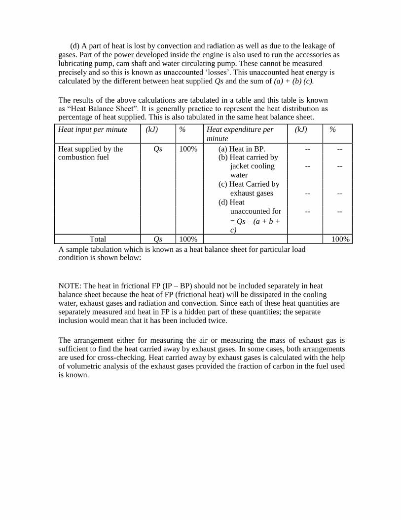
The results of the above calculations are tabulated in a table and this table is known as “Heat Balance Sheet”. It is generally practice to represent the heat distribution as percentage of heat supplied. This is also tabulated in the same heat balance sheet.
Heat input per minute (kJ) % Heat expenditure per (kJ) %
minute
Heat supplied by the Qs 100% (a) Heat in BP. -- -- combustion fuel (b) Heat carried by
jacket cooling -- --
water
(c) Heat Carried by
exhaust gases -- -- (d) Heat
unaccounted for -- --
= Qs – (a + b + c)
Total Qs 100% 100% A sample tabulation which is known as a heat balance sheet for particular load condition is shown below:
NOTE: The heat in frictional FP (IP – BP) should not be included separately in heat balance sheet because the heat of FP (frictional heat) will be dissipated in the cooling water, exhaust gases and radiation and convection. Since each of these heat quantities are separately measured and heat in FP is a hidden part of these quantities; the separate inclusion would mean that it has been included twice.
The arrangement either for measuring the air or measuring the mass of exhaust gas is sufficient to find the heat carried away by exhaust gases. In some cases, both arrangements are used for cross-checking. Heat carried away by exhaust gases is calculated with the help of volumetric analysis of the exhaust gases provided the fraction of carbon in the fuel used is known.