Embed Size (px)
Citation preview

UNIT II
ELECTRICAL AND ELECTRONICS INSTRUMENTS
Principle and types of analog and digital voltmeters, ammeters, multi meters – single and three phase
wattmeter’s and energy meters – magnetic measurements – determination of B-H curve and
measurements of iron loss – instrument transformers – instruments for measurement of frequency and
phase.
Theory Permanent Magnet Moving Coil (PMMC) Instruments
The general theory of moving-coil instruments may be dealt with considering a rectangular coil of turns,
free to rotate about a vertical axis. N
Fig. 42.1(a) shows the basic construction of a PMMC instrument. A moving coil instrument consists
basically of a permanent magnet to provide a magnetic field and a small lightweight coil is wound on a
rectangular soft iron core that is free to rotate round
IV SEM - MEASUREMENTS & INSTRUMENTATION
its vertical axis. When a current is passed through the coil windings, a torque is developed on the coil
by the interaction of the magnetic field and the field set up by the current in the coil. The aluminum
pointer attached to rotating coil and the pointer moves around the calibrated scale indicates the
deflection of the coil. To reduce parallax error a mirror is usually placed along with the scale. A balance
weight is also attached to the pointer to counteract its weight (see Fig.). To use PMMC device as a
meter, two problems must be solved. First, a way must be found to return the coil to its original position
when there is no current through the coil. Second, a method is needed to indicate the amount of coil
movement. The first problem is solved by the use of hairsprings attached to each end of the coil as
shown in Fig. These hairsprings are not only supplying a restoring torque but also provide an electric
connection to the rotating coil. With the use of hairsprings, the coil will return to its initial position when
no current is flowing though the coil. The springs will also resist the movement of coil when there is
current through coil. When the developing force between the magnetic fields (from permanent magnet
and electro magnet) is exactly equal to the force of the springs, the coil rotation will stop. The coil set
up is supported on jeweled bearings in order to achieve free movement. Two other features are
considered to increase the accuracy and efficiency of this meter movement. First, an iron core is placed
inside the coil to concentrate the magnetic fields. Second, the curved pole faces ensure the turning force
on the coil increases as the current increases.
It is assumed that the coil sides are situated in a uniform radial magnetic field of flux density2/
Bwbm, let the length of a coil side (within the magnetic field) be (meter), and the distance from each
coil side to the axis be (meter). lr
Principle of operation
It has been mentioned that the interaction between the induced field and the field produced by
the permanent magnet causes a deflecting torque, which results in rotation of the coil. The deflecting
torque produced is described below in mathematical form:
Truly speaking, the equation (42.2) is valid while the iron core is cylindrical and the air gap between
the coil and pole faces of the permanent magnet is uniform. This result the flux density B is constant
and the torque is proportional to the coil current and instrument scale is linear.
Controlling Torque: The value of control torque depends on the mechanical design of the control device.
For spiral springs and strip suspensions, the controlling torque is directly proportional to the angle of
deflection of the coil.
Ie Control torque =C θ (42.3)
where,
θ = deflection angle in radians and = spring constant C/. Nm rad

Damping Torque: It is provided by the induced currents in a metal former or core on which
the coil is wound or in the circuit of the coil itself. As the coil moves in the field of the permanent
magnet, eddy currents are set up in the metal former or core. The magnetic field produced by the eddy
currents opposes the motion of the coil. The pointer will therefore swing more slowly to its proper
position and come to rest quickly with very little oscillation. Electromagnetic damping is caused by the
induced effects in the moving coil as it rotates in magnetic field, provided the coil forms part of closed
electric circuit.
Deflecting torque:
If the coil is carrying a current of I am, the force on a coil side B il N (Newton N)
Torque due to both coil side = (2r) (Bil N) (N m)
Where G is the galvanometer constant and is expressed as G=2 r BlN (Nm/amp)
=NBA (Nm/amp)
Where A= 2rl= area of Coil.
N=no of turns of the coil.
B=flux density in Wb/m2
L=length of the vertical side of the coil,m
2r=breath of the coil.
I=current in ampere.
A= 2rl= area, m2
Equation of motion: the resulting torque in a coil or motion of a coil in a magnetic field is due to
D d
the combined effect of deflecting torque (Td) controlling torque(Cθ) damping torque dt and it is
expressed mathematically as
d2
d Jd2
Dd
j 2 = Gi –C
dt – D
dt =
dt2 + dt
+ c = G I

Where J is the moment of inertia of moving parts. One can easily study the dynamic behavior of the
above second order system by solving the differential equation
Remarks: When the moving system reached at steady state i.e. at final deflected position, the
controlling torque becomes equal and opposite to the deflecting torque. The deflecting angle is directly
proportional to the current in the movable coil (see eq). For this reason, the scale of the moving coil
instrument is calibrated linearly
Multi-range ammeters and voltmeters
An ammeter is required to measure the current in a circuit and it therefore connected in series
with the components carrying the current. If the ammeter resistance is not very much smaller than the
load resistance, the load current can be substantially altered by the inclusion of the ammeter in the
circuit. To operate a moving coil instrument around a current level 50ma is impractical owing to the
bulk and weight of the coil that would be required. So, it is necessary to extend the meter-range shunts
(in case of ammeters) and multipliers (in case of volt meters) are used in the following manner.
For higher range ammeters a low resistance made up of managing (low temperature coefficient
of resistance) is connected in parallel to the moving coil (see Fig.) and instrument may be calibrated to
read directly to the total current.
They are called shunts. The movement of PMMC instrument is not inherently insensitive to
temperature, but it may be temperature-compensated by the appropriate use of series and shunt resistors
of copper and managing. Both the magnetic field strength and spring-tension decrease with an increase
in temperature. On other side, the coil resistance
increases with an increase in temperature. These changes lead to make the pointer read low for a given
current with respect to magnetic field strength and coil resistance. Use of manganic resistance (known
as swamping resistance which has a temperature coefficient practically zero) in series with the coil

resistance can reduce the error due to the variation of resistance of the moving coil. The swamping
resistance () is usually three times that of coil thereby reducing a possible error of, say, 4% to 1%. A
multiage ammeter can be constructed simple by employing several values of shunt resistances, with a
rotary switch to select the desired range. Fig. 42.2(b) shows the circuit arrangement’s
When an instrument is used in this fashion, care must be taken to ensure shunt does not become
open-circuited, even for a very short instant. When the switch is moved from position ‗B‘ to
‗C ‘or moved to any positions, the shunt resistance will remain open-circuited for a fraction of time,
resulting a very large current may flow through the ammeter and damage the instrument. To avoid such
situation, one may use the make-before-break switch as shown in Fig.42.(c).
The wide-ended moving contact connected to the next terminal to which it is being moved before it
loses contact with the previous terminals. Thus, during the switching time there are two resistances are
parallel with the instrument and finally the required shunt only will come in parallel to the instrument
When an instrument is used in this fashion, care must be taken to ensure shunt does not become open
circuit, even for a very short instant. When the switch is moved from the position B to C or moved to
any position, the shunt resistance will remain open circuit for a fraction of time, resulting a very large
current may flow through the ammeter and damage the instrument .to avoid such situation, one may use
the make before break switch as shown in fig.
Multi-range voltmeter: A dc voltmeter is constructed by a connecting a resistor in series with a PMMC
instrument. Unlike an ammeter, a voltmeter should have a very high resistances R and it is normally
connected in parallel with the circuit where the voltage is to be measured (see Fig.42.4). To minimize
voltmeter loading, the voltmeter operating current should be very small i.e., the resistance connected in
series with the coil should be high.

The moving coil instrument can be suitable modified to act either as an ammeter or as a voltmeter. For
multi range voltmeter the arrangement is follows as shown in fig. any one of several multiplier resistor
is selected by means of rotary switch. Unlike the case of the ammeter, the rotary switch used with the
voltmeter should be a break before make, type, that is, moving contact should be disconnect from one
terminal before connecting to the next terminal
Advantages, Limitations and sources of errors
Advantages:
• The scale is uniformly divided (see at steady state ,sGICθ=).
• The power consumption can be made very low(25200WtoWμμ).
• The torque-weight ratio can be made high with a view to achieve high accuracy.
• A single instrument can be used for multi range ammeters and voltmeters.
• Error due to stray magnetic field is very small.
Limitations:
• They are suitable for direct current only.
• The instrument cost is high.
• Variation of magnet strength with time.
The Errors are due to:
i) Frictional error,
ii) Magnetic decay,
iii) Thermo electric error,
iv) Temperature error.
Errors can be reduced by following the steps given below:
• Proper pivoting and balancing weight may reduce the frictional error.
• Suitable aging can reduce the magnetic decay.
• Use of managing resistance in series (swamping resistance) can nullify the effect of variation of
resistance of the instrument circuit due to temperature variation.
• The stiffness of spring, permeability of magnetic core (Magnetic core is the core of electromagnet or
inductor which is typically made by winding a coil of wire around a ferromagnetic material) decreases
with increases in temperature.
Ammeter Sensitivity:
Ammeter sensitivity is determined by the amount of current required by the meter coil to
produce full-scale deflection of the pointer. The smaller the amount of current required producing this
deflection, the greater the sensitivity of the meter. A meter movement that requires only 100
microamperes for full- scale deflection has a greater sensitivity than a meter movement that requires 1
mA for the same deflection.
Voltmeter Sensitivity:
The sensitivity of a voltmeter is given in ohms per volt. It is determined by dividing the sum of
the resistance of the meter (R ), plus the series resistance (R ), by the full-scale reading in volts. m s
Construction and Basic principle operation of Moving-iron Instruments
We have mentioned earlier that the instruments are classified according to the principles of operation.
Furthermore, each class may be subdivided according to the nature of the movable system and method
by which the operating torque is produced. Specifically, the electromagnetic instruments are sub-
classes as (i) moving-iron instruments (ii) electro-dynamic or dynamometer instruments, (iii) induction
instruments. In this section, we will discuss briefly the basic principle of moving-iron instruments that
are generally used to measure alternating voltages and currents. In moving –iron instruments the
movable system consists of one or more pieces of specially-shaped soft iron, which are so pivoted as to
be acted upon by the magnetic field produced by the current in coil. There are two general types of
moving-iron instruments namely (i) Repulsion (or double iron) type (ii) Attraction (or single-iron) type.
The brief description of different components of a moving-iron instrument is given below.
• Moving element: a small piece of soft iron in the form of a vane or rod
• Coil: to produce the magnetic field due to current flowing through it and also to magnetize the iron
pieces.
• In repulsion type, a fixed vane or rod is also used and magnetized with the same polarity.
• Control torque is provided by spring or weight(gravity)
• Damping torque is normally pneumatic, the damping device consisting of an air chamber and a
moving vane attached to the instrument spindle.
• Deflecting torque produces a movement on an aluminum pointer over a graduated scale.
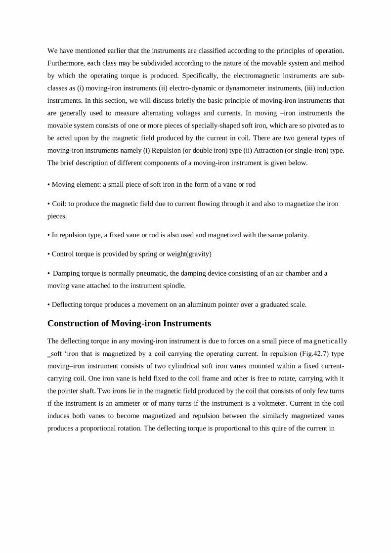
Construction of Moving-iron Instruments
The deflecting torque in any moving-iron instrument is due to forces on a small piece of magnetically
‗soft ‘iron that is magnetized by a coil carrying the operating current. In repulsion (Fig.42.7) type
moving–iron instrument consists of two cylindrical soft iron vanes mounted within a fixed current-
carrying coil. One iron vane is held fixed to the coil frame and other is free to rotate, carrying with it
the pointer shaft. Two irons lie in the magnetic field produced by the coil that consists of only few turns
if the instrument is an ammeter or of many turns if the instrument is a voltmeter. Current in the coil
induces both vanes to become magnetized and repulsion between the similarly magnetized vanes
produces a proportional rotation. The deflecting torque is proportional to this quire of the current in

the coil, making the instrument reading is a true ‗RMS ‘quantity Rotation is opposed by a hairspring
that produces the restoring torque. Only the fixed coil carries load current, and it is constructed so as to
withstand high transient current. Moving iron instruments having scales that are nonlinear and
somewhat crowded in the lower range of calibration. Another type of instrument that is usually classed
with the attractive types of instrument is shown inFig.42.8.
This instrument consists of a few soft iron discs (B) that are fixed to the Spidle, pivoted in
jeweled bearings. The spindle also carries a pointer, a balance weight, a controlling weight and a
damping piston (DDP1W2WE), which moves in a curved fixed cylinder. The special shape of the
moving-iron discs is for obtaining a scale of suitable form. F

Remark: Moving-iron vanes instruments may be used for DC current and voltage measurements and
they are subject to minor frequency errors only. The instruments may be effectively shielded from the
influence of external magnetic fields by enclosing the working parts, except the pointer, in a laminated
iron cylinder with laminated iron end covers.
Torque expression:
Torque expression may be obtained in terms of the inductance of the instrument. Suppose the
initial current is I the instrument inductance l and the deflection θ. Then let I change to i+dI being a
small change of the current as a result let θ change to (θ+d θ) and the L to (l+dl). In order to get an
instrument change in current di there must be an increase in the applied voltage across coil.
V =dLI = I dl+ L di
The applied voltage dt dt dt
The electric energy supplied to the coils in dt is
V I dt = i2dl + IL dI
Increase in energy stored in the magnetic field = ½ (I+dI)2 (L+dL)- ½ I2 L
(Neglecting second and higher order terms in small quantity)
If the T is the value of the control torque corresponding to deflection θ the extra energy stored in the
control due to the changed θ to T d θ . The stored increase in stored
energy= IL d I + ½ i 2 d L + T d
From the principle of the conversion of energy, one can write the flowing expression
Electric energy drawn from the supply =increases in stored energy + mechanical work done.
Controlling torque
I spring control Ts=Ks θ where Ks is the spring.
II Gravity control TG=KG sin θ
Ranges of Ammeters and Voltmeters
For a given moving-iron instrument the ampere-turns necessary to produce full-scale deflection are
constant. One can alter the range of ammeters by providing a shunt coil with the moving coil.
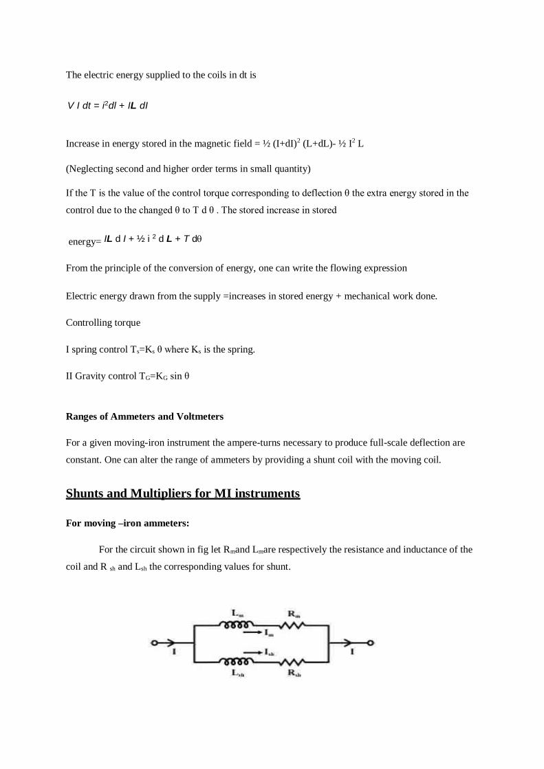
Shunts and Multipliers for MI instruments
For moving –iron ammeters:
For the circuit shown in fig let Rmand Lmare respectively the resistance and inductance of the
coil and R sh and Lsh the corresponding values for shunt.

m m m
m m se m
The ratio of current in two parallel
Ish= Im
The above ratio will be independent of the frequency ω provided that he time constants of the parallel
Lm
two branches are sameRm =Lsh
Rm
In other words
IshIm
= Rm Rsh
Now
I = Ish + I m = Im Rm+1Rsh
Rm+ 1.
Multipliers for the shunt = It is difficult to design a shuntwith the appropriate
inductance and shunts are rarely incorporated in moving iron ammeters. thus the multiplier for the
Rm+ 1.
shunt = it is difficult to design a shunt with the appropriate inductance and shuntare
rarely incorporated in moving iron ammeters. Thus the multi range can effectively be obtained by
winding the instrument coil in section which may be connected in series, parallel or series parallel
combination which in turn change the total ampere in the magnetizing coil.
For moving –iron voltmeters:
Voltmeter ranges may be altered connecting a resistance in series with the coil. Hence the same
coil winding specification may be employed for a number of ranges. Let us considered a high resistance
Rse is connected in series with the moving coil and it shown in fig.
V = I R 2 + (w L )2
V = I (R + R )2 + (w L )2
Multiplier
V= v
Rsh
Rsh

Note: An ordinary arrangement with a non-inductive resistance in series with the fixed coil-result in
error that increase as the frequency increases .the change of the impedance of the instrument with change
of frequency error; multiplier may be easily shunted by the capacitor.
Advantages:
• The instruments are suitable for use in a.c and d.c circuits.
• The instruments are robust, owing to the simple construction of the moving parts.
• The stationary parts of the instruments are also simple.
• Instrument is low cost compared to moving coil instrument.
• Torque/weight ratio is high, thus less frictional error.
Errors:
i. Errors due to temperature variation.
ii. Errors due to friction is quite small as torque-weight ratio is high in moving-iron instruments.
iii. Stray fields cause relatively low values of magnetizing force produced by the coil. Efficient
magnetic screening is essential to reduce this effect.
iv. Error due to variation of frequency causes change of reactance of the coil and also changes the
eddy currents induced in neighboring metal.
v. Deflecting torque is not exactly proportional to the square of the current due to non-linear
characteristics of iron material.

Induction type meters
GENERAL THEORY
Induction type instruments are used only on a.c. circuits. All induction type instruments consist
of 2 windings and an aluminum disc. When alternating currents flow through the windings, fluxes 1
and 2 are produced. Both these fluxes induce emfs E1 and E2 in the disc or drum and circulate eddy
currents I1 and I2 respectively. Therefore 2 torques are produced by:
1st flux Ф interacting with eddy current I2produced by other flux 2nd
flux Ф 2 interacting with eddy current I1 produced by other flux
Total torque is the sum of these 2 torques. Let and 2 be instantaneous values of 2 fluxes having a
phase difference of and therefore,
1= m1sinwt
2= m
2sinwt
Where r.m.s values are,

1= 0.707m1
2=0.707m
2
Flux 1 produces an emf in the disc by transformer action. The instantaneous value of this emf is,
e1 d dt) dm1(sinwt m1cost) - f
m1 cos t)
dt
Therefore e1 lags flux by 90o. Let E1 be r.m.s value of emf e1, then
E10.707(fm
1)
f0.707(fm
1)1
If impedance of eddy current path Z, then eddy current,
I1 = E1=f
lags E1byan angle Z Z
Average torque produced by the interaction of and I1 is,
Td12I1cos(90°–+)
Td
121fcos(90°–+) z

Similarly,
Average torque produced by the interaction of and I1 is,
Td
21I2cos(90°–+)
Td
221fcos(90°–+) z
Applying Fleming ‘s left hand rule, the two torques act in opposite direction,
Td = Td1 – Td2
Td=
21
fcos(90°–+)–21fcos(90°–+)
z z
Td21 fsincosz
Solving we get,
For torque to be large,
(i) as possible.
(ii) Angle Ф12should be almost 90o. Hence two fluxes must be displaced by90o.
Induction type energy meter
Energy is the total power delivered or consumed over a time interval, i.e.,
Energy = Power x Time
Electrical energy developed as work or dissipated as heat over an interval of time t is,W= v idt
Energy is an integrating type of instrument used for measurement of energy in domestic and industrial
a.c. circuits.
Single phase induction type energy meter
Construction:
There are 4 main parts:
Driving System:
Consist of 2 electromagnets made of silicon steel laminations
Coil of one of the electromagnet (shunt magnet) is excited by load current known as current coil
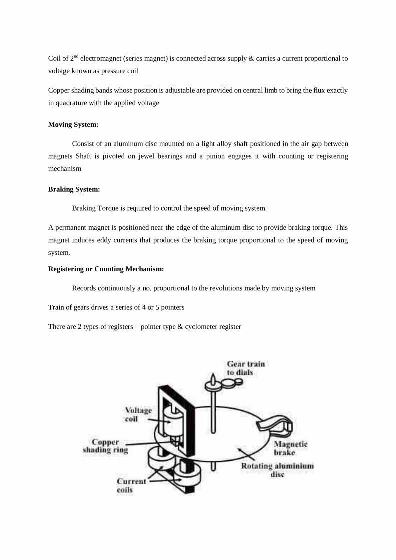
Coil of 2nd electromagnet (series magnet) is connected across supply & carries a current proportional to
voltage known as pressure coil
Copper shading bands whose position is adjustable are provided on central limb to bring the flux exactly
in quadrature with the applied voltage
Moving System:
Consist of an aluminum disc mounted on a light alloy shaft positioned in the air gap between
magnets Shaft is pivoted on jewel bearings and a pinion engages it with counting or registering
mechanism
Braking System:
Braking Torque is required to control the speed of moving system.
A permanent magnet is positioned near the edge of the aluminum disc to provide braking torque. This
magnet induces eddy currents that produces the braking torque proportional to the speed of moving
system.
Registering or Counting Mechanism:
Records continuously a no. proportional to the revolutions made by moving system
Train of gears drives a series of 4 or 5 pointers
There are 2 types of registers – pointer type & cyclometer register

Theory and operation:
Supply voltage V is applied across pressure coil. As pressure coil is highly inductive with a
small resistance then current Ip that flow through the coil, lags it by a few degrees less than 90o. Current
Ip produces flux Фpt, which consist of Фg and Фp. Flux Фg flows across side gaps whereas flux Фp links
with the disc and eddy emf Eep is induced in it. This in turn produces eddy current Iep which lags Eep by
an angle as the path of eddy current is inductive. Load current I flows through current coil and
produce flux Фs proportional to it. This flux induces eddy emf Ees in the disc. As a result, eddy current
Ies flows through it and lags it by an angle Фb Two torques are produced – Td1 by the interaction of Фs
with Iep and Td2 by the interaction of Фg with Ies, acting in the opposite direction. Net torque is the
difference of these two torques.
Let Ф – phase angle of load
Δ- Phase angle between the supply voltage and pressure coil flux
f – Frequency
Z - Impedance of eddy current paths
Net Driving Torque, Tdps
fsincos= K1ps fsincos
z z
Where
K1 is a constant
β was phase angle between fluxes Ф 1 and Ф 2. From phasor diagram, angle between fluxes Ф p and
Ф s isФ
Td = K1ps fsin(– ) cosz
pV andsI
Td = K2ps fsin(– ) cosz
If f, Z and α are constant,
Td = K3psI sin(– ) cos
Braking Torque, TB = K4N where N is the steady speed
At steady speed, TB= Td
K4N = K3psI sin(– )

N = K3 K4 psI sin(– )
if Δ= 90o then,
N = K VI cos Ф = K x Power
Total no. of revolutions = ∫N dt
=∫K VI cos Ф dt
= K ∫ Power (dt)
= K x Energy
Lag Adjustment / Power Factor Adjustment / Quadrature Adjustment / Inductive load Adjustment:
In order to make the angle between fluxes 90o, a magnetic shunt circuit known as lag
coil is introduced. The pressure coil is excited by voltage V and carries a current Ip which produces an
mmf ATpt which in turn produces a flux Ф pt lagging the voltage by an angle 90o- . But only flux Ф p
links with lag coil. As a result, a voltage EL is induced in the coil lagging by 90o and this circulates
current IL through it. The lag coil produces an mmf ATL. The flux Ф p that links with the disc is created
by the combined action of main mmf A Tpt in phase with Ip and lag coil mmf ATL in phase with IL. Thus
this flux Ф p will be in phase with the resultant mmf ATp. By varying mmf of lag coil either in magnitude
or in phase we can adjust the phase of flux Фp.
Arrangements for adjusting the mmf of the lag coil are:
Adjustable resistance:
A few turns of thick wire are placed around central limb of shunt magnet and
circuit is closed through a low adjustable resistance. An increase in resistance decreases current and mmf
ATL and hence lag angle Ф decreases. Decreases in resistance increases current and mmf ATL and
hence lag angle increases. Thus angle can be adjusted.
Shading bands:
In this copper shading bands L1 are placed on central limb. When shading bands are
moved up the limb it embraces more flux and hence mmf ATL increases resulting in an increase in
θ when shading bands a removed down, mmf ATL decreasesandhenceФ decreases Thus, angle
can be adjusted.
Light Load or Friction Compensation:
At light loads, error due to friction is high. Hence a small torque is provided which is
independent of the load, and is equal in magnitude to the frictional torque. For this, a shading loop L2
is situated between the center pole of the shunt magnet and the disc. The interaction between the
portions of the flux, which are shaded and unshaded by this loop and the current in the disc induce a
small driving torque whose value can be adjusted by lateral movement of the loop.

Creep:
- In some meters a slow but continuous rotation is obtained even when only pressure coil is
energized. (i.e; there is no current flowing in current coil). This is called creeping.
- Major cause is overcompensation of friction. This occurs when the friction compensating device is
such that it compensates the starting friction (Starting Friction > Running Friction)
- Other causes are excessive voltage across potential coil, vibrations, stray magnetic fields
- To prevent creeping two diametrically opposite holes are drilled in the disc. The disc will come to rest
with one of the holes under the edge of a pole of the shunt magnet, the rotation thus limited to a
maximum of half revolution. If a hole is under the edge of a pole the eddy current path is distorted and
the effective center is A ‘. As a result, there is a force on the disc tending to move A ‘away from pole
axis A. But further rotation of disc is opposed. The magnitude of this opposing torque is not sufficient
to rotate the disc in other direction.
- Another method is by attaching a small iron piece to edge of disc. Force of attraction between brake
magnet and iron piece prevents creeping.
Overload Compensation:
- When disc revolves continuously in field of series magnet under load conditions, there is a
dynamically induced emf in the disc. This causes eddy currents to interact with field of series magnet
to produce self - braking torque TSB.
TSB =Load Current 2
- To minimize this,
Full load speed of disc is kept low almost 40 rpm.
Фs is kept small as compared to Фp
Overload compensating device is added which takes the form of a magnetic shunt for the series magnet
that diverts flux Фs.
Voltage Compensation:
- Energy meters must be compensated for variation in voltage as this can cause errors as shunt
magnet flux: is not linear with supply voltage owing to saturation
produces dynamically induced emf that produces self-braking torque TSB
TSB = Supply Voltage2
- Compensation is provided using storable magnetic shunt, which diverts flux or by providing holes in
side limbs of shunt magnet

Temperature Compensation:
- Increase in temperature increases resistance of metal parts resulting in:
(i) Decrease in potential coil flux & reduction in angle of lag between V and
(ii) Decrease in torque produced by all shading bands
(iii) Increase in resistance of eddy current paths
(iv) Decrease in angle of lag of eddy currents
- These effects neutralize each other
- Error is serious at low power factors
- Compensation is provided using temperature shunt on brake magnet
Errors:
Errors caused by driving system are:
(i) Incorrect magnitude of fluxes – caused by abnormal values of voltage, current, frequency and
change in resistance of coil
(ii) Incorrect phase angles – caused by improper lag adjustments, abnormal frequencies, change in
resistance
(iii) Lack of symmetry in magnetic circuit – causes creep
Errors caused by braking system are:
Changes in strength of brake magnets
Changes in disc resistance
Self-braking effect
Abnormal friction of moving parts
Adjustments:
Some adjustments are carried out in energy meters so that they read correctly. They are,
Preliminary Light Load Adjustment:
Disc is so positioned that the holes are not underneath the electromagnets
Rated voltage applied to pressure coil with no current in current coil
Light load device adjusted until disc just fails to start
Full load unity power factor adjustment
Rated voltage applied to pressure coil
Rated full load current at up passed through current coil
Position of brake magnet adjusted so that disc revolves at correct speed
Lag Adjustment (Low power factor Adjustment)
Rated voltage applied to pressure coil
Rated full load current at 0.5 pf lagging passed through current coil
- Lag device adjusted so that disc revolves at correct speed
Full load unity power factor adjustment and Low power factor Adjustment
Rated voltage applied to pressure coil
Rated full load current at up passed through current coil
Full load unity power factor adjustment & low power factor adjustment done so that disc revolves at
correct speed
Light Load Adjustment
Rated voltage applied to pressure coil
Low current passed through current coil at up
Light Load Adjustment done so that disc revolves at correct speed
Full load unity power factor and Light Load Adjustment are gain done so that disc revolves at correct
speed
Performance is rechecked at 0.5 pf lagging
Creep adjustment - Pressure coil is excited by 110% of rated voltage with zero load current. At this
condition meter should not creep
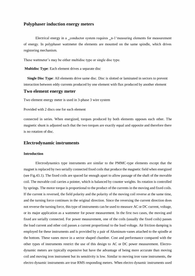
Polyphaser induction energy meters
Electrical energy in a ‗conductor system requires ‗n-1‘measuring elements for measurement
of energy. In polyphaser wattmeter the elements are mounted on the same spindle, which drives
registering mechanism.
These wattmeter’s may be either multidisc type or single disc type.
Multidisc Type: Each element drives a separate disc
Single Disc Type: All elements drive same disc. Disc is slotted or laminated in sectors to prevent
interaction between eddy currents produced by one element with flux produced by another element
Two element energy meter
Two element energy meter is used in 3-phase 3 wire system
Provided with 2 discs one for each element
connected in series. When energized, torques produced by both elements opposes each other. The
magnetic shunt is adjusted such that the two torques are exactly equal and opposite and therefore there
is no rotation of disc.
Electrodynamic instruments
Introduction
Electrodynamics type instruments are similar to the PMMC-type elements except that the
magnet is replaced by two serially connected fixed coils that produce the magnetic field when energized
(see Fig.43.1). The fixed coils are spaced far enough apart to allow passage of the shaft of the movable
coil. The movable coil carries a pointer, which is balanced by counter weights. Its rotation is controlled
by springs. The motor torque is proportional to the product of the currents in the moving and fixed coils.
If the current is reversed, the field polarity and the polarity of the moving coil reverse at the same time,
and the turning force continues in the original direction. Since the reversing the current direction does
not reverse the turning force, this type of instruments can be used to measure AC or DC current, voltage,
or its major application as a wattmeter for power measurement. In the first two cases, the moving and
fixed are serially connected. For power measurement, one of the coils (usually the fixed coils) passes
the load current and other coil passes a current proportional to the load voltage. Air friction damping is
employed for these instruments and is provided by a pair of Aluminum-vanes attached to the spindle at
the bottom. These vanes move in a sector shaped chamber. Cost and performance compared with the
other types of instruments restrict the use of this design to AC or DC power measurement. Electro-
dynamic meters are typically expensive but have the advantage of being more accurate than moving
coil and moving iron instrument but its sensitivity is low. Similar to moving iron vane instruments, the
electro dynamic instruments are true RMS responding meters. When electro dynamic instruments used

for power measurement its scale is linear because it predicts the average power delivered to the load
and it is calibrated in average values for AC. Voltage, current and power can all be measured if the fixed
and moving coils are connected appropriately. Other parts of the instruments are described briefly
below:
Electro dynamic (or Dynamometer) type Instruments:
Fixed coil: The magnetic field is produced by the fixed coil which is divided into two sections
to give more uniform field near the center and to allow passage of the instrument shaft.
Moving coil: The moving coil is wound either as a self-sustaining coil or else on a non-magnetic
former. A metallic former cannot be used, as eddy currents would be induced in it by alternating field.
Light but rigid construction is used for the moving coil. It should be noted that both fixed and moving
coils are air cored.
Springs: The controlling torque is provided by two control springs. These hairsprings also act as leads
of current to the moving coil.
Dampers: Air friction damping is employed for these instruments and is provided by a pair of
Aluminum-vanes attached to the spindle at the bottom. These vanes move in a sector shaped chamber.
Shielding: Since the magnetic field produced by fixed coils is weaker than that in other types of
instruments, these meters need a special magnetic shielding. Electro-dynamic instruments are
effectively shielded from the effects of external magnetic fields by enclosing the mechanism in a
laminated iron hollow cylinder with closed ends.

Operating Principle
Let us consider the currents in the fixed and moving coils are fi and respectively. The action of
electrodynamic instrument depends upon the force exerted between fixed and moving coils carrying
current. The flux density produced by the fixed coil is proportional to (fixed coil current). The force on
the conductors of the moving coil, for a given strength field, will proportional to (moving coil current)
and the number of turns ‗‘ of the moving coil. In case of ammeter and voltmeter fixed and moving coils
are connected in series and the developed torque is due to the interaction of the magnetic fields produced
by currents in the fixed and moving coils and thus it will be proportional
Thus, dynamic instruments can be used for dc and ac measurements. to
Expression for developed torque:
Let us assume that the fixed and moving coil having self-inductance Lf and Lm respectively
. further it is assumed that the mutual inductance between the fixed and movable coil is M.
Total energy stored in the magnetic field of the coil is given by
W = 1l i2 + 1l i2 + M l i2
2f f
2m m fm
Where Ifand Im are the current through the fixed and moving coil. From the above equation for the
torque developed
Td = dw= ifimdm
d d
L eq= L+Lm+2M
And form mutual inductance between them
M = 1[Leq – (Lf + Lm)]
2
With all deflection type instrument, however the mutual inductance varies with the relative position of
the moving coil and fixed coil. The maximum value M max of the mutual inductance occur when the
axis of the moving and fixed coil are lined with θ=180 as this position gives the maximum flux linage
between coils. When θ=0‘, M=-m max. if the plane of the moving coil is at an angle θ with the direction
of the B that produced by the fixed coil. then the mutual inductance expressed in M=- Mmax
T
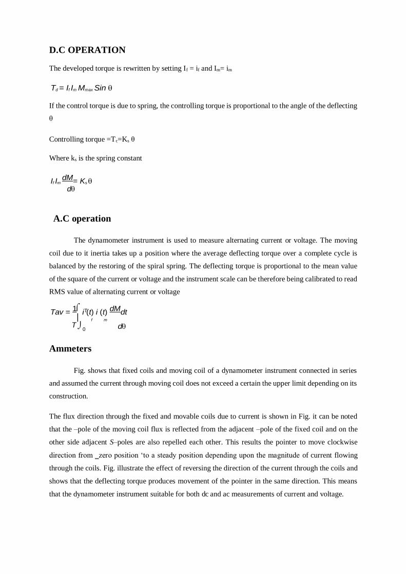
D.C OPERATION
The developed torque is rewritten by setting If = if and Im= im
Td = If Im Mmax Sin
If the control torque is due to spring, the controlling torque is proportional to the angle of the deflecting
θ
Controlling torque =Tc=Ks θ
Where ks is the spring constant
If Im dM= Ks
d
A.C operation
The dynamometer instrument is used to measure alternating current or voltage. The moving
coil due to it inertia takes up a position where the average deflecting torque over a complete cycle is
balanced by the restoring of the spiral spring. The deflecting torque is proportional to the mean value
of the square of the current or voltage and the instrument scale can be therefore being calibrated to read
RMS value of alternating current or voltage
Tav = 1
i (t) i (t) dMdt f m
0 d
Ammeters
Fig. shows that fixed coils and moving coil of a dynamometer instrument connected in series
and assumed the current through moving coil does not exceed a certain the upper limit depending on its
construction.
The flux direction through the fixed and movable coils due to current is shown in Fig. it can be noted
that the –pole of the moving coil flux is reflected from the adjacent –pole of the fixed coil and on the
other side adjacent S–poles are also repelled each other. This results the pointer to move clockwise
direction from ‗zero position ‘to a steady position depending upon the magnitude of current flowing
through the coils. Fig. illustrate the effect of reversing the direction of the current through the coils and
shows that the deflecting torque produces movement of the pointer in the same direction. This means
that the dynamometer instrument suitable for both dc and ac measurements of current and voltage.
T

The dynamic instrument when uses as a voltmeter, the fixed coils wounded with thin wire are
connectedinserieswiththemovingcoilandanon-inductiveresistanceFig.Forammeterapplication the fixed
coils are connected in parallel with the moving coil, and in parallel with a shunt, as required (see
Fig.43.4). NN
Remarks: The scale of the instrument can be conveniently calibrated on dc and then used to measure
ac.
Ranges of Ammeters and Voltmeters
Ammeters
A given size of instruments requires a definite number of ampere-turns to be supplied by the
fixed and moving coils to obtain a full–scale deflection. Ammeter ranges are altered by changing the
number of turns and size of conductor in the fixed and moving coils. A double range instrument may
easily be obtained by connecting different coil sections either in series or in parallel. The internal
connections are shown in Fig.43.3. The maximum range for which ammeters are usually constructed is
dependent on its application. For ammeter use in which only fraction of rated current (say 200 ma) is
carried by the moving coil to alter its range by changing the mode of connection of the fixed coils.
Voltmeters: With voltmeters the ranges are altered by changing the number of turns in the coils and the
value of series resistances, but the range of a given instrument may be increased by connecting
additional resistances in series with it. For example, the range of a given voltmeter may be doubled
while connecting in series with it a non–inductive resistance equal in value to the original resistance of
the instrument.

Connections for ammeter, voltmeter and wattmeter Ammeter
When ammeters for ranges above about 250, the moving coil cannot be connected in series with the
fixed coil (note the control spring is unsuitable for currents above about 250). Therefore, the moving
coil must be connected in parallel with the fixed coils as shown in Fig 43.4.
Here the moving coil current is kept within 200 mA and the rest of current is passed
through the fixed coil. Moving coil carries a small fraction of measured current through the moving
coil. For extreme accuracy the connection shown in Fig. 43.4 must fulfill the following conditions.
• The resistance/reactance ratio must have the same value (i.e. time constant of moving coil = time
constant of fixed coil) for each branch.
• ThepercentagechangeofresistancewithtemperaturemustbethesameforthetwoTheconnection for
use as a voltmeterisshowninFig.43.5, in which fixed and moving coils are connected in series with
a high series resistance having―zero resistivity co-efficient ‖.
Voltmeters
Voltmeter: the connection for use as a voltmeter is shown in fig. in which fixed and moving coil are
connected in series with a high resistance having ‗Zero resistivity co-efficient.

Remarks: Electro-dynamic meter‘s use is much more common for ac voltmeters than for ac ammeters.
Wattmeter: Perhaps the most important use of the electrodynamometer is for the wattmeter. The
mechanism of electro dynamic wattmeter closely resembles that of an electro-dynamic ammeter, but
the moving coil of wattmeter is connected in series with a high non–inductive resistance.
Advantages and disadvantages of electro-dynamic instruments
Advantages:
i Free from hysteresis and eddy current errors.
ii Applicable to both dc and ac circuits.
iii Precision grade accuracy for 40 Hz to 500Hz.
iv Electro-dynamic voltmeters give accurate r.m.s values of voltage irrespective of waveforms.
Disadvantages:
i Low torque/weight ratio, hence more frictional errors.
ii More expensive than PMMC or MI instruments.
iii Power consumption higher than PMMC but less than MI instruments.

For these reasons, dynamometer ammeters and voltmeters are not in common use (except for calibration
purpose) especially in dc circuits. The most important application of the dynamometer type instruments
used as dynamometer wattmeter
Frequency meters
Frequency meters are instruments used to indicate frequency. The different types of frequency
meters are:
MECHANICAL RESONANCE TYPE OR VIBRATING REED TYPE
FREQUENCY METER
Construction:
Reeds
- Thin steel strips called reeds are placed in a row alongside close to an electromagnet.
All reeds are similar with their natural frequencies of vibration different (as they have slightly
different dimensions) & are arranged in ascending order of frequencies.
- Reeds are fixed at bottom end and are free at top end with a portion bend to serve as flag.
Electromagnet
- Electromagnet has a laminated iron core on which coil is wound. The coil is connected in series
across the supply whose frequency is to be measured.
Vibrating Reed
Reed
Type Frequency Meter
Operation:

Frequency Meter is connected across the supply whose frequency is to be measured the coil of
electromagnet carries a current i, which alternates at the supply frequency. The force of attraction
between the reeds and the electromagnet is proportional to i2and therefore this force varies twice at the
frequency supply frequency. Thus, the force exerted on the reeds varies every half cycle. All the reeds
tend to vibrate, but the reed whose natural frequency is equal to twice the frequency of supply tends to
vibrate the most. Vibration of other reeds is unobservable.
Variation of amplitude of vibrations with frequency For a frequency exactly midway between that of the
reeds, both will vibrate with amplitudes with equal magnitude.
Electrical resonance type
Two types of electrical Resonance Meters are described below:
Ferro dynamic type of frequency
meter: Construction:
Magnetizing Coil
- Consists of a fixed coil called magnetizing coil, which is connected across the supply whose
frequency is to be measured
- It is mounted on a laminated iron core
Iron core
- Cross section of iron core varies gradually over the length being maximum near the end where
magnetizing coil is mounted and minimum at the other end.
Moving Coil
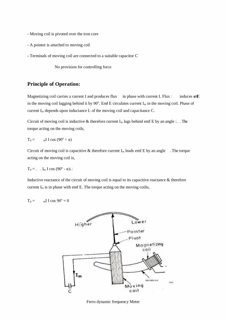
- Moving coil is pivoted over the iron core
- A pointer is attached to moving coil
- Terminals of moving coil are connected to a suitable capacitor C
No provision for controlling force
Principle of Operation:
Magnetizing coil carries a current I and produces flux in phase with current I. Flux induces emf E
in the moving coil lagging behind it by 90o. Emf E circulates current Im in the moving coil. Phase of
current Im depends upon inductance L of the moving coil and capacitance C.
Circuit of moving coil is inductive & therefore current Im lags behind emf E by an angle . The
torque acting on the moving coils,
Td = mI I cos (90o + α)
Circuit of moving coil is capacitive & therefore current Im leads emf E by an angle . The torque
acting on the moving coil is,
Td = Im I cos (90o - α)
Inductive reactance of the circuit of moving coil is equal to its capacitive reactance & therefore
current Im is in phase with emf E. The torque acting on the moving coilis,
Td = mI I cos 90o = 0
Ferro dynamic frequency Meter

Working:
For a fixed frequency, capacitive reactance is constant but inductive reactance of
moving coil depends upon the position it occupies on the iron core. Inductive reactance is maximum
when moving coil occupies a position close to the magnetizing coil and is minimum at the other end.
The figure shows the position of moving coil at normal frequency. At this position,
inductive reactance is equal to the capacitive reactance.
Suppose the frequency increases above its normal value then, XL> XC& therefore
torque is produced. This torque pulls the moving coil to an equilibrium position i.e., moving coil deflects
towards the section of iron core having minimum cross section. So inductive reactance decreases and
moving coil comes to rest at a position where XL = XC.
Suppose the frequency decreases below its normal value then, XL< XC& therefore
torque is produced. This torque pulls the moving coil to an equilibrium position i.e., moving coil
deflects towards the section of iron core having maximum cross section. So inductive reactance
increases and moving coil comes to rest at a position where XL = XC.
Advantage:
Great sensitivity
Electrodynamometer type of frequency meter:
Construction:
Fixed coil
Fixed coil is divided into two parts 1 and 2 which forms two separates resonant circuits
- Fixed coil 1 is in series with an inductance L1 and a capacitance C1 forming a resonant circuit of
frequencyf1.
- Fixed coil 2 is in series with an inductance L2 and a capacitance C2 forming a resonant circuit of
frequencyf2.
Moving Coil
- Current through the moving coil is sum of the currents through the 2 parts of fixed coil
- Torque on the movable element is proportional to the current through the moving coil

A small iron vane mounted on the moving system provides controlling torque.
Electrodynamometer type frequency meter
Operation:
At a particular frequency, the current through circuit of fixed coil 1 lags
behind applied voltage (as XL1>XC1) while the current through circuit of fixed coil 2 leads applied
voltage (as XL2<XC2). Therefore, torques produced by 2 coils act in opposition on the moving coil. The
resultant torque is a function of frequency of the applied voltage.
Application:
- For power frequency measurements
- In power system, for monitoring the frequency
Power factor meters
Power Factor meters indicate directly, the power factor of the circuit to which they are connected.
General Construction:
Current Circuit that carries the current in the circuit whose power factor is to be measured
Pressure Circuit is connected across the circuit whose power factor is to be measured
Pressure circuit is split into 2 parallel paths - one inductive and other non-inductive

Operation:
Deflection of pointer depends upon the phase difference (i.e. cos between the main current and
the currents in the two paths of pressure circuit Moving system is perfectly balanced at equilibrium
position by 2 opposing forces & therefore there is no need for controlling torque. Hence, when a
power factor meter is disconnected from a circuit the pointer remains at the position, which it
occupied at the instant of disconnection.
The different types of power factor meters are:
Electrodynamometer power factor meter
Single phase electrodynamometer power factor meter
Construction:
Fixed Coil or Current Coil
- Current Coil is split into 2parts
- It carries current of circuit under test and produces magnetic field proportional to the main current
Pressure Coil or Moving Coil
- There are 2 identical pressure coils A and B connected across the voltage of the circuit
- Pressure coil A has a non-inductive resistance R connected in series with it.
- Pressure coil B has a highly inductive choke coil L connected in series with it.
- Current through coil A is in phase with the circuit voltage while that in coil B lags voltage by an
angle , which is nearly equal to90o
- Angle between the plane of the coils A & B is also
- At normal frequency, values of L and R are such that current through both the coils have same
magnitude i.e., R = L
- Connections to the moving coils are made through thin silver or gold ligaments

Single Phase Electrodynamometer Power Factor Meter
Operation:
Let‘s assume that current through coil B lags the voltage by exactly 90o. Therefore, angle between plane
of coils is 90o. Let be the angular deflection from the plane of reference and Mmax be the maximum
value of mutual inductance. Consider the case of lagging power factor:
Deflecting torque acting on coil A,
TA = K V I Mmax cos Ф sin θ
Deflecting torque acting on coil B,
TB = K V I Mmax cos (90o - Ф ) sin (90o + θ)
TB = K V I Mmax sin Ф cos θ
The two torques acts in opposite direction. The coil will take up a position such that the two torques are
equal. Hence at equilibrium,
TA = TB
K V I Mmax cos θ sin = K V I Mmax sin Ф cos θ
Thus, deflection of the instrument is a measure of phase angle of the circuit. Scale of instrument can
be directly calibrated in terms of powerfactor.

Disadvantage:
Error in the indication may be caused by change in reactance of the coil due to,
change in supply frequency (other than the one it is calibrated at)
presence of harmonics in the supply
Three phase electrodynamometer power factor meter
Construction:
Fixed Coil or Current Coil – similar to that of single phase
Pressure Coil or Moving Coil
- There are 2 identical pressure coils A and B connected across two different phases of the circuit
- Each coil has only a series resistance & therefore current through both the coils (IA& IB) are in phase
with applied voltage
- Required phase displacement between current IA& IB is obtained from supply itself
- Hence, angle between the plane of the coils is120o
3-phase electrodynamometer power factor meter
Operation:

Assume,
V12 – voltage applied across coil A
V13 – voltage applied across coil B
V12 = V13 =V
Let be the angular deflection from the plane reference and the maximum value of mutual inductance.
Consider the case of lagging power factor:
Deflecting torque acting on coil A,
TA=KV12IMmaxcos(30o+Ф)sin(60o+θ) = KVIM cos(30o+
Ф) sin (60o + θ)
Deflecting torque acting on coil B,
TB = K V13I Mmax cos (30o - Ф ) sin (120o+ θ ) K V I Mmax cos(30o
- Ф ) sin (120o + θ )
The two torques acts in opposite direction. The coil will take up a position such that the two
torques are equal. Hence at equilibrium,
TA = TB K V I Mmax cos (30o + Ф) sin (60o+ θ) K V I Mmax cos (30o - sin Ф) (120o+ θ)
Solving,
Thus, deflection of the instrument is a measure of phase angle of the circuit
Advantage:

Error due to change in frequency is eliminated as currents in both the coils are equally affected.
Moving iron power factor meter
According to principle of operation these may be classified as,
Rotating field power factor meter
Three phase rotating field power factor meter
Construction:
Fixed Coils
A1, A2, A3 are three fixed coils connected respectively in lines 1, 2 and 3 of 3-phase supply through
current transformers Axes of A1, A2 and A3 are120o displaced from each other and intersecting on the
central line of the instrument Equivalent moving coil- Fixed coil P is connected in series with a high
resistance across one pair of lines (2 &3)
Iron cylinder C is placed inside the coil P pivoted on a spindle. Two sector shaped iron vanes 180o
apart are fixed to the cylinder
Spindle also carries damping vanes and a pointer
Iron Cylinder, Vanes and coil P are equivalent electromagnetically to a rectangular moving coil
There are no control springs
Rotating Field Moving Iron Power Factor Meter

Operation:
Current Ip, which is in phase with and proportional to line voltage (due to the large resistance in series),
magnetizes coil P and the vanes. The alternating flux produced interacts with the fluxes produced by
coils A1, A2 and A3. This causes moving system to take up a position determined by the phase angle
of the system.
Total deflecting torque,
Td 1IIpcos (90o – ) sin (90o+ ) + I2 Ipcos (330o – ) sin (210o+ ) + I3Ip cos (210o – )sin (330o +
)]
For a steady deflection, the total torque must be zero. Also considering system to be balanced i.e., I1 =
I2 = I3, we have,
cos (90o – ) sin (90o + ) + cos (330o – ) sin (210o + ) + cos (210o – ) sin (330o + ) = 0
Solving Note:
The three fixed coils A1, A2, A3 produce a rotating magnetic field. In order to prevent induction motor
action high resistivity metal is used for the moving irons so as to reduce the values of induced currents.
Single phase rotating field power factor meter
Construction:
Fixed coils
A1, A2, A3 are three fixed coils connected respectively in lines 1, 2 and 3 of 3-phase supply with
resistor R, inductor L and a capacitor C in series with it respectively.
Current in coil A1 is in phase with the line voltage
Current in coil A2 lags by 600
Current in coil A3 leads 60o
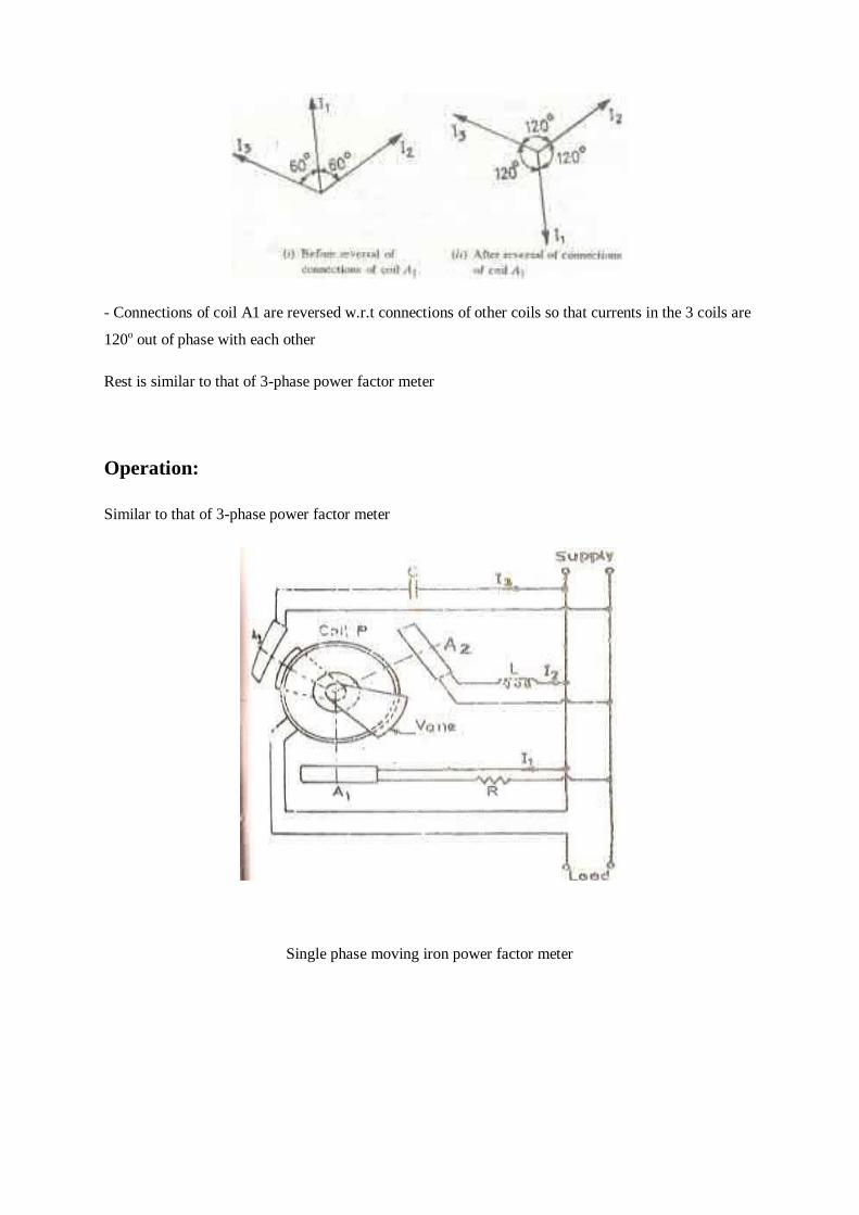
- Connections of coil A1 are reversed w.r.t connections of other coils so that currents in the 3 coils are
120o out of phase with each other
Rest is similar to that of 3-phase power factor meter
Operation:
Similar to that of 3-phase power factor meter
Single phase moving iron power factor meter
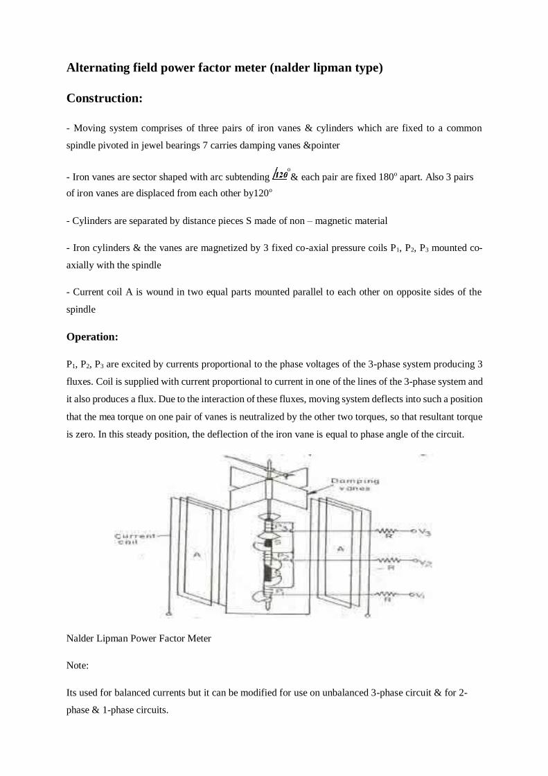
Alternating field power factor meter (nalder lipman type)
Construction:
- Moving system comprises of three pairs of iron vanes & cylinders which are fixed to a common
spindle pivoted in jewel bearings 7 carries damping vanes &pointer
- Iron vanes are sector shaped with arc subtending o
& each pair are fixed 180o apart. Also 3 pairs
of iron vanes are displaced from each other by120o
- Cylinders are separated by distance pieces S made of non – magnetic material
- Iron cylinders & the vanes are magnetized by 3 fixed co-axial pressure coils P1, P2, P3 mounted co-
axially with the spindle
- Current coil A is wound in two equal parts mounted parallel to each other on opposite sides of the
spindle
Operation:
P1, P2, P3 are excited by currents proportional to the phase voltages of the 3-phase system producing 3
fluxes. Coil is supplied with current proportional to current in one of the lines of the 3-phase system and
it also produces a flux. Due to the interaction of these fluxes, moving system deflects into such a position
that the mea torque on one pair of vanes is neutralized by the other two torques, so that resultant torque
is zero. In this steady position, the deflection of the iron vane is equal to phase angle of the circuit.
Nalder Lipman Power Factor Meter
Note:
Its used for balanced currents but it can be modified for use on unbalanced 3-phase circuit & for 2-
phase & 1-phase circuits.

No rotating magnetic field is produced here
Advantage of Moving Iron power factor meter
Working forces are very large
All coils are fixed. Hence the use of ligaments is
eliminated Scale extends over 360o
Simple & robust in construction
Cheap
Disadvantage of Moving Iron power factor meter
Less accurate due to iron losses
Calibration is affected by variations in supply frequency, voltage & waveform
Magnetic measurements
Ballistic galvanometer
It is used for the measurement of quantity of electricity passed through it. It is due to the result of an
instantaneous emf induced in search coil connected across the ballistic galvanometer terminals. The
quantity of electricity passing through the galvanometer is proportional to the emf induced and hence
to the change in the flux linking with the search coil.

When we pass a current through a galvanometer it
does not reach its steady state deflection immediately but there is a time interval or
period of transition during which the galvanometer deflects from zero position to final
steady position. Dynamic behavior of galvanometer during this period is examined by
the equation of motion. The constants of galvanometer are known as intrinsic
constants.
The different torque acting on the moving system are
1. Deflecting Torque(Td): It is for deflecting the pointer from initial zero position.
Td=BANi
B= Flux
density
in air
gap
A=Area
of coil
N= Number of turns
i = Current through the galvanometer.
2. Inertia Torque (Tj): A retarding torque is produced due to inertia of moving
system. This torque depends upon the moment of inertia of the moving system and
angular acceleration.
Tj = J d2θ/dt2
J = Moment of inertia of moving system, θ =deflection at any time.
3. Damping Torque (TD): Damping is provided by the friction due the motion of
the coil in air and also by induced electrical effects, if a closed circuit is provided.
T
D= D
dθ/dt
D=
damp
ing
const
ant.
4. Controlling Torque (Tc): It is provided due to the elasticity of the system which
tries to restore the moving system back to its original position.
Tc = kθ , k= Control constant
Flux meter
It is a special type of ballistic galvanometer in which the controlling torque is very
small and the electromagnetic damping is heavy.
The construction is similar to that of a moving coil mille ammeter. A coil of small
cross section is suspended from a spring supported by means of a single silk thread.
The coil moves in the narrow gap of a permanent magnet. There are no control springs.
The current is lead in to the coil with the help of a very loose helices of thin, annealed
silver strips. The controlling torque is thus reduced to minimum. The coil is former
less and air friction damping is negligible.
The terminals of the flux meter are connected to a search coil. The flux linking
with the search coil is changed either by removing the coil from the magnetic field or
by reversing the field. Due to the change in the value of the flux linking with the search
coil an emf is induced in it. This emf send a current through the flux meter which
deflects through an angle depending upon the change in the value of the flux linkages.
If the flux meter permanent magnet field is uniform for all positions of the moving
coil, G is a constant. Change in the value of the flux is directly proportional to the
change in the deflection. So the instrument has a uniform scale.

Lloyd – fisher square
This is the most commonly used magnetic square and therefore it is
described in greater details. The strips used are usually 0.25 m long and 50 to 60 mm
wide. These strips are built up into four stacks. Each stack is made up of two types of
strips one cut in the direction of rolling and other cut perpendicular to the direction of
rolling. The stacks or strips are placed inside four similar magnetizing coils of large
cross sectional area. These four coils are connected in series to form the primary
winding. Each magnetizing coil has two similar single layer coils underneath it. They
are called secondary coils. These secondary coils are connected in series in groups of
four, one from each core to form two separate secondary windings.
The ends of the strips project beyond the magnetizing coils.
The strips are so arranged that plane of each strip is perpendicular to the plane of the
square. The magnetic circuit is completed by bringing the four stacks together in the
form of a square and joining them at the corners. Measured loss has to be corrected
for the loss in the corner pieces.