Embed Size (px)
Citation preview
UNIT HEATERS FOR STEAM OR HOT WATER
Ro
sem
ex P
rod
uct
s
HEAT
ING
01 2009
2
FEATURESBROAD RANGE OF APPLICATION
• Hot water or steam ROSEMEX unit heaters provide eco-nomical ‘‘space comfort’’ for industrial, commercial and insti-tutional applications.
• Horizontal models H and HS in 13 sizes; up to 492 MBH.
• Vertical models V and VS in 13 sizes; up to 685 MBH.
• Greater throw with ‘‘low outlet temperature» HS and VS units(with high pressure steam).
• Maximum flexibility of air distribution with optional diffuserarrangements.
• Units with special coil available on request: copper fins oncopper tubes, steel fins on either steel, Bundyweld steel(copper plated steel), copper or red brass tubes.
APPEARANCE
• Compact and attractive. Modern design enhanced by alu-minium semi-gloss finish.
HIGH PERFORMANCE
• More CFM for lower outlet air temperature.
• Quieter operation with lower RPM motors.
• Greater air throw and circulation.
• Top opening on V models helps recover warm air at ceiling.
• Suitable for higher temperature drops.
• HS and VS units have wider fin spacing allowing for higherCFM and higher outlet velocities for even greater throw.
• Accurately rated in accordance with AMCA bulletins # 20and 22.
• Guaranteed to be free from defects in material or workman-ship for a period of one year from date of purchase.
RUGGED ‘‘LONG-LIFE’’ CONSTRUCTION
• Casing: die formed, reinforced steel.
• Finish: sheet metal chemically degreased, phosphatized andetched. Semi-gloss ‘‘grey’’ paint finish.
• Coil: steel pipe headers, copper tubes, ribbed aluminumplate fins. Red brass tubes, heavy 0.035’’ wall is standard onHS and VS models, optional on all other models, andrecommended for steam over 5 PSIG. All coils tested with200 PSIG air pressure under water.
• Motors: specially selected and tested; thermally protected;permanently lubricated for a minimum of 20,000 hours on Hand HS models, and 20,000 hours on V and VS models.Motors totally enclosed on H and HS models.
• Motor mounts: rugged, corrosion resistant. All motors or sup-ports resiliently mounted.
• Fans: aluminum blades; sturdy, balanced, efficient and quiet.
EASY MAINTENANCE
• All parts fully accessible for maintenance, service or replace-ment.
• Motors readily accessible on model H units, and easilyremovable through fan opening on model V units.
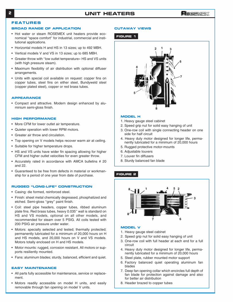
CUTAWAY VIEWS
FIGURE 1
MODEL H1. Heavy gauge steel cabinet2. Speed grip nut for solid easy hanging of unit3. One-row coil with single connecting header on one
side for half circuit4. Heavy duty motor designed for longer life, perma-
nently lubricated for a minimum of 20,000 hours5. Rugged protective motor-mounts6. Adjustable louvers7. Louver fin diffusers8. Sturdy balanced fan blade
FIGURE 2
MODEL V1. Heavy gauge steel cabinet2. Speed grip nut for solid easy hanging of unit3. One-row coil with full header at each end for a full
circuit4. Heavy duty motor designed for longer life, perma-
nently lubricated for a minimum of 20,000 hours5. Steel plate, rubber mounted motor support6. Factory balanced quiet operating aluminum fan
blades7. Deep fan opening collar which encircles full depth of
fan blade for protection against damage and alsofor better air distribution
8. Header brazed to copper tubes
UNIT HEATERS
3
GENERAL SELECTIONHEAT LOSSES
Should be calculated according toASHRAE Guide or other reliablesource.
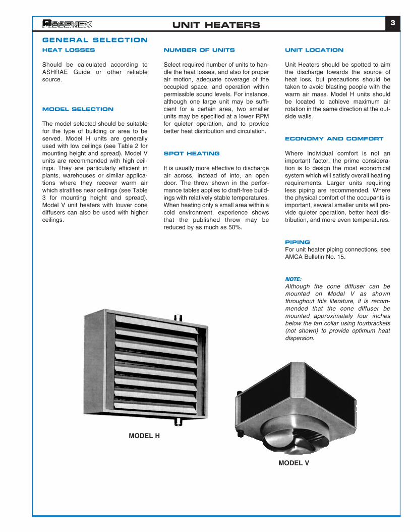
MODEL SELECTION
The model selected should be suitablefor the type of building or area to beserved. Model H units are generallyused with low ceilings (see Table 2 formounting height and spread). Model Vunits are recommended with high ceil-ings. They are particularly efficient inplants, warehouses or similar applica-tions where they recover warm airwhich stratifies near ceilings (see Table3 for mounting height and spread).Model V unit heaters with louver conediffusers can also be used with higherceilings.
NUMBER OF UNITS
Select required number of units to han-dle the heat losses, and also for properair motion, adequate coverage of theoccupied space, and operation withinpermissible sound levels. For instance,although one large unit may be suffi-cient for a certain area, two smallerunits may be specified at a lower RPMfor quieter operation, and to providebetter heat distribution and circulation.
SPOT HEATING
It is usually more effective to dischargeair across, instead of into, an opendoor. The throw shown in the perfor-mance tables applies to draft-free build-ings with relatively stable temperatures.When heating only a small area within acold environment, experience showsthat the published throw may bereduced by as much as 50%.
UNIT LOCATION
Unit Heaters should be spotted to aimthe discharge towards the source ofheat loss, but precautions should betaken to avoid blasting people with thewarm air mass. Model H units shouldbe located to achieve maximum airrotation in the same direction at the out-side walls.
ECONOMY AND COMFORT
Where individual comfort is not animportant factor, the prime considera-tion is to design the most economicalsystem which will satisfy overall heatingrequirements. Larger units requiringless piping are recommended. Wherethe physical comfort of the occupants isimportant, several smaller units will pro-vide quieter operation, better heat dis-tribution, and more even temperatures.
PIPINGFor unit heater piping connections, seeAMCA Bulletin No. 15.
NOTE:Although the cone diffuser can bemounted on Model V as shownthroughout this literature, it is recom-mended that the cone diffuser bemounted approximately four inchesbelow the fan collar using fourbrackets(not shown) to provide optimum heatdispersion.
MODEL H
MODEL V
UNIT HEATERS
UNIT HEATERS
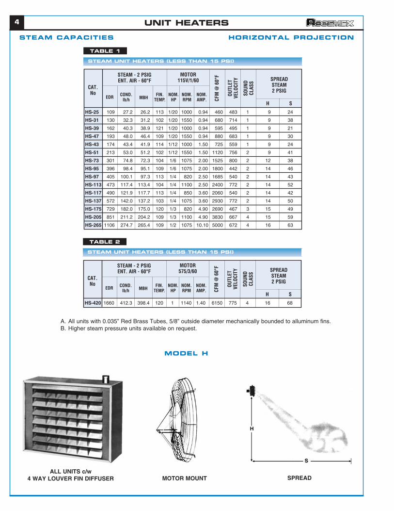
STEAM CAPACITIES HORIZONTAL PROJECTION
4
SPREADMOTOR MOUNTALL UNITS c/w
4 WAY LOUVER FIN DIFFUSER
MODEL H
HS-25 109 27.2 26.2 113 1/20 1000 0.94 460 483 1 9 24
HS-31 130 32.3 31.2 102 1/20 1550 0.94 680 714 1 9 38
HS-39 162 40.3 38.9 121 1/20 1000 0.94 595 495 1 9 21
HS-47 193 48.0 46.4 109 1/20 1550 0.94 880 683 1 9 30
HS-43 174 43.4 41.9 114 1/12 1000 1.50 725 559 1 9 24
HS-51 213 53.0 51.2 102 1/12 1550 1.50 1120 756 2 9 41
HS-73 301 74.8 72.3 104 1/6 1075 2.00 1525 800 2 12 38
HS-95 396 98.4 95.1 109 1/6 1075 2.00 1800 442 2 14 46
HS-97 405 100.1 97.3 113 1/4 820 2.50 1685 540 2 14 43
HS-113 473 117.4 113.4 104 1/4 1100 2.50 2400 772 2 14 52
HS-117 490 121.9 117.7 113 1/4 850 3.60 2060 540 2 14 42
HS-137 572 142.0 137.2 103 1/4 1075 3.60 2930 772 2 14 50
HS-175 729 182.0 175.0 120 1/3 820 4.90 2690 467 3 15 49
HS-205 851 211.2 204.2 109 1/3 1100 4.90 3830 667 4 15 59
HS-265 1106 274.7 265.4 109 1/2 1075 10.10 5000 672 4 16 63
STEAM UNIT HEATERS (LESS THAN 15 PSI)
TABLE 1
STEAM - 2 PSIGENT. AIR - 60°F
MOTOR115V/1/60
CAT.No
EDR COND.lb/h MBH
FIN.TEMP.
NOM.HP
NOM.RPM
NOM.AMP. CF
M @
60°
F
OUTL
ETVE
LOCI
TY
SOUN
DCL
ASS SPREAD
STEAM2 PSIG
H S
HS-420 1660 412.3 398.4 120 1 1140 1.40 6150 775 4 16 68
STEAM UNIT HEATERS (LESS THAN 15 PSI)
TABLE 2
STEAM - 2 PSIGENT. AIR - 60°F
MOTOR575/3/60
CAT.No
EDR COND.lb/h MBH
FIN.TEMP.
NOM.HP
NOM.RPM
NOM.AMP. CF
M @
60°
F
OUTL
ETVE
LOCI
TY
SOUN
DCL
ASS SPREAD
STEAM2 PSIG
H S
A. All units with 0.035” Red Brass Tubes, 5/8” outside diameter mechanically bounded to alluminum fins.B. Higher steam pressure units available on request.
5
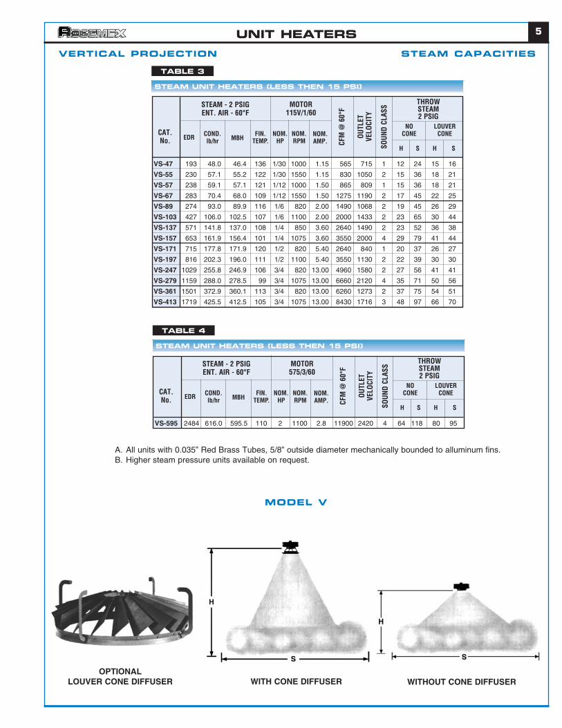
VERTICAL PROJECTION STEAM CAPACITIES
MODEL V
WITHOUT CONE DIFFUSERWITH CONE DIFFUSEROPTIONAL
LOUVER CONE DIFFUSER
VS-47 193 48.0 46.4 136 1/30 1000 1.15 565 715 1 12 24 15 16
VS-55 230 57.1 55.2 122 1/30 1550 1.15 830 1050 2 15 36 18 21
VS-57 238 59.1 57.1 121 1/12 1000 1.50 865 809 1 15 36 18 21
VS-67 283 70.4 68.0 109 1/12 1550 1.50 1275 1190 2 17 45 22 25
VS-89 274 93.0 89.9 116 1/6 820 2.00 1490 1068 2 19 45 26 29
VS-103 427 106.0 102.5 107 1/6 1100 2.00 2000 1433 2 23 65 30 44
VS-137 571 141.8 137.0 108 1/4 850 3.60 2640 1490 2 23 52 36 38
VS-157 653 161.9 156.4 101 1/4 1075 3.60 3550 2000 4 29 79 41 44
VS-171 715 177.8 171.9 120 1/2 820 5.40 2640 840 1 20 37 26 27
VS-197 816 202.3 196.0 111 1/2 1100 5.40 3550 1130 2 22 39 30 30
VS-247 1029 255.8 246.9 106 3/4 820 13.00 4960 1580 2 27 56 41 41
VS-279 1159 288.0 278.5 99 3/4 1075 13.00 6660 2120 4 35 71 50 56
VS-361 1501 372.9 360.1 113 3/4 820 13.00 6260 1273 2 37 75 54 51
VS-413 1719 425.5 412.5 105 3/4 1075 13.00 8430 1716 3 48 97 66 70
STEAM UNIT HEATERS (LESS THEN 15 PSI)
TABLE 3
STEAM - 2 PSIGENT. AIR - 60°F
MOTOR115V/1/60
CAT.No. EDR COND.
lb/hr MBHFIN.
TEMP.NOM.
HP
NOCONE
H S H S
LOUVERCONENOM.
RPMNOM.AMP. CF
M @
60°
F
OUTL
ETVE
LOCI
TY
THROWSTEAM2 PSIG
SOUN
D CL
ASS
VS-595 2484 616.0 595.5 110 2 1100 2.8 11900 2420 4 64 118 80 95
STEAM UNIT HEATERS (LESS THEN 15 PSI)
TABLE 4
STEAM - 2 PSIGENT. AIR - 60°F
MOTOR575/3/60
CAT.No. EDR COND.
lb/hr MBHFIN.
TEMP.NOM.
HP
NOCONE
H S H S
LOUVERCONENOM.
RPMNOM.AMP. CF
M @
60°
F
OUTL
ETVE
LOCI
TYTHROWSTEAM2 PSIG
SOUN
D CL
ASS
UNIT HEATERS
A. All units with 0.035” Red Brass Tubes, 5/8” outside diameter mechanically bounded to alluminum fins.B. Higher steam pressure units available on request.
6
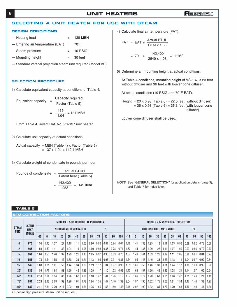
SELECTING A UNIT HEATER FOR USE WITH STEAM
DESIGN CONDITIONS
— Heating load = 139 MBH
— Entering air temperature (EAT) = 70°F
— Steam pressure = 10 PSIG
— Mounting height = 30 feet
— Standard vertical projection steam unit required (Model VS).
SELECTION PROCEDURE
1) Calculate equivalent capacity at conditions of Table 4.
Capacity requiredEquivalent capacity = ————————
Factor (Table 5)
139= ——— = 134 MBH
1.04
From Table 4, select Cat. No. VS-137 unit heater.
2) Calculate unit capacity at actual conditions.
Actual capacity = MBH (Table 4) x Factor (Table 5)= 137 x 1.04 = 142.4 MBH
3) Calculate weight of condensate in pounds per hour.
Actual BTUHPounds of condensate = ——————————
Latent heat (Table 5)
142,400= ———— = 149 lb/hr
953
4) Calculate final air temperature (FAT).
Actual BTUHFAT = EAT + ——————
CFM x 1.08
142,400= 70 + —————— = 119°F
2640 x 1.08
5) Determine air mounting height at actual conditions.
At Table 4 conditions, mounting height of VS-137 is 23 feetwithout diffuser and 36 feet with louver cone diffuser.
At actual conditions (10 PSIG and 70°F EAT).
Height = 23 x 0.98 (Table 6) = 22.5 feet (without diffuser)= 36 x 0.98 (Table 6) = 35.3 feet (with louver cone
diffuser)
Louver cone diffuser shall be used.
NOTE: See ‘‘GENERAL SELECTION’’ for application details (page 3),and Table 7 for noise level.
BTU CORRECTION FACTORS
TABLE 5
-10 0 10 20 30 40 50 60 70 80 90 100
0 970 1.54 1.45 1.37 1.27 1.19 1.11 1.03 0.96 0.88 0.81 0.74 0.67
2 966 1.59 1.50 1.41 1.32 1.24 1.16 1.08 1.00 0.93 0.85 0.78 0.71
5 961 1.64 1.55 1.46 1.37 1.29 1.21 1.13 1.05 0.97 0.90 0.83 0.76
10 953 1.73 1.64 1.55 1.46 1.38 1.29 1.21 1.13 1.06 0.98 0.91 0.84
15 945 1.80 1.71 1.61 1.53 1.44 1.34 1.28 1.19 1.12 1.04 0.97 0.90
20* 939 1.86 1.77 1.68 1.58 1.50 1.42 1.33 1.25 1.17 1.10 1.02 0.95
50* 911 2.13 2.04 1.94 1.85 1.76 1.67 1.58 1.50 1.42 1.34 1.26 1.19
75* 894 2.28 2.18 2.09 1.99 1.90 1.81 1.72 1.64 1.55 1.47 1.40 1.32
100* 880 2.41 2.31 2.20 2.11 2.02 1.93 1.84 1.75 1.66 1.58 1.50 1.42
-10 0 10 20 30 40 50 60 70 80 90 100
1.48 1.41 1.33 1.25 1.18 1.11 1.03 0.96 0.89 0.82 0.75 0.69
1.52 1.44 1.36 1.29 1.22 1.14 1.07 1.00 0.93 0.86 0.79 0.73
1.57 1.49 1.41 1.33 1.26 1.19 1.11 1.05 0.98 0.91 0.84 0.77
1.64 1.56 1.48 1.40 1.33 1.25 1.18 1.11 1.04 0.97 0.90 0.84
1.69 1.61 1.53 1.46 1.38 1.31 1.24 1.17 1.10 1.03 0.96 0.90
1.73 1.65 1.57 1.50 1.42 1.35 1.28 1.21 1.14 1.07 1.00 0.94
1.93 1.85 1.77 1.70 1.63 1.55 1.48 1.42 1.35 1.28 1.21 1.15
2.04 1.97 1.90 1.82 1.75 1.68 1.61 1.54 1.47 1.40 1.33 1.27
2.15 2.07 1.99 1.92 1.85 1.77 1.70 1.63 1.56 1.49 1.43 1.36
STEAMPSIG
LATENTHEAT
BTUH/lb
MODELS H & HS HORIZONTAL PROJECTION
ENTERING AIR TEMPERATURE °F
MODELS V & VS VERTICAL PROJECTION
ENTERING AIR TEMPERATURE °F
* Special high pressure steam unit on request.
UNIT HEATERS
7
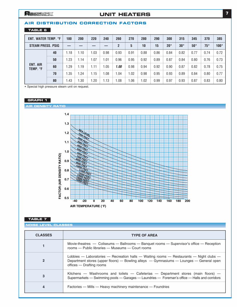
AIR DISTRIBUTION CORRECTION FACTORS
ENT. WATER TEMP. °F 180 200 220 240 260 270 280 290 300 315 345 370 385
STEAM PRESS. PSIG — — — — 2 5 10 15 20* 30* 50* 75* 100*
40 1.18 1.10 1.03 0.98 0.93 0.91 0.88 0.86 0.84 0.82 0.77 0.74 0.72
50 1.23 1.14 1.07 1.01 0.96 0.95 0.92 0.89 0.87 0.84 0.80 0.76 0.73
60 1.29 1.19 1.11 1.05 1.00 0.98 0.94 0.92 0.90 0.87 0.82 0.78 0.75
70 1.35 1.24 1.15 1.08 1.04 1.02 0.98 0.95 0.93 0.89 0.84 0.80 0.77
80 1.43 1.30 1.20 1.13 1.08 1.06 1.02 0.99 0.97 0.93 0.87 0.83 0.80
NOISE LEVEL CLASSES
TABLE 7
AIR DENSITY RATIO
GRAPH 1
TABLE 6
ENT. AIRTEMP. °F
Movie-theatres — Coliseums — Ballrooms — Banquet rooms — Supervisor’s office — Receptionrooms — Public libraries — Museums — Court rooms
Lobbies — Laboratories — Recreation halls — Waiting rooms — Restaurants — Night clubs —Department stores (upper floors) — Bowling alleys — Gymnasiums — Lounges — General openoffices — Drafting rooms
Kitchens — Washrooms and toilets — Cafeterias — Department stores (main floors) —Supermarkets — Swimming pools — Garages — Laundries — Foreman’s office — Halls and corridors
Factories — Mills — Heavy machinery maintenance — Foundries
1
2
3
4
CLASSES TYPE OF AREA
0.5
0.6
0.7
0.8
0.9
1.0
1.1
1.2
1.3
1.4
-40
AIR TEMPERATURE (°F)
FA
CT
OR
(A
IR D
EN
SIT
Y R
AT
IO)
-20 0 20 40 60 80 100 120 140 160 180 200
SEA LEVEL1000 FEET2000 FEET
3000 FEET4000 FEET5000 FEET6000 FEET7000 FEET8000 FEET9000 FEET10000 FEET11000 FEET12000 FEET13000 FEET
14000 FEET15000 FEET
* Special high pressure steam unit on request.
UNIT HEATERS
8
23.5 3.20 2.70 92 28.4 3.90 3.60 98
22.1 2.30 1.50 90 27.0 2.70 2.00 96
19.3 1.30 0.60 86 24.3 1.70 0.9 93
16.7 0.90 0.30 83 21.6 1.10 0.40 98
33.0 3.30 4.10 94 39.9 4.10 5.60 102
29.7 2.00 1.70 91 36.7 2.50 2.40 98
26.5 1.40 0.90 88 33.5 1.70 1.30 95
37.1 3.80 5.00 90 45.0 4.60 6.90 97
33.4 2.30 2.10 97 41.3 2.80 3.00 94
29.8 1.50 1.10 84 37.7 1.90 1.60 91
52.5 7.00 0.85 93 63.0 8.37 1.17 100
46.6 4.66 0.40 90 57.7 5.77 0.58 97
37.8 3.10 0.19 84 50.4 4.00 0.30 92
42.0 2.75 0.15 87
58.8 11.76 2.20 104 70.0 14.00 3.05 102
54.0 7.20 0.88 93 65.8 8.88 1.29 100
48.0 4.80 0.42 89 60.2 6.02 0.64 96
33.0 2.25 0.10 80 45.5 3.00 0.17 88
73.8 9.90 1.70 98 84.0 11.25 2.20 103
69.6 6.96 0.89 96 82.5 8.25 1.23 102
54.0 3.50 0.25 88 70.0 4.62 0.42 96
61.3 3.10 0.16 91
85.4 11.39 2.22 93 101.5 13.50 3.08 99
81.6 8.16 1.21 91 98.0 9.80 1.68 98
69.0 4.62 0.42 87 87.5 5.88 0.63 94
52.4 2.65 0.15 80 71.7 3.62 0.26 88
99.0 13.20 2.13 97 117.2 15.62 2.90 104
96.0 9.60 1.18 96 114.1 11.41 1.62 103
84.0 5.60 0.44 91 103.6 6.90 0.64 99
70.2 3.50 0.18 86 91.0 4.50 0.30 94
105.0 14.00 2.37 93 124.3 16.62 3.25 99
103.2 10.32 1.36 92 121.1 12.11 1.82 98
93.0 6.20 0.52 89 114.1 7.62 0.76 96
78.0 3.95 0.22 85 100.1 5.00 0.36 92
145.4 19.39 2.55 98 172.9 23.00 3.43 105
135.0 13.50 1.30 95 164.5 16.45 1.85 103
117.0 7.75 0.47 91 145.2 9.70 0.71 98
99.0 5.00 0.21 86 127.7 6.37 0.33 93
151.4 20.19 2.80 97 176.7 23.50 3.60 105
143.3 14.34 1.48 95 173.2 17.32 2.09 102
123.0 8.15 0.52 90 154.0 10.25 0.79 97
104.4 5.25 0.23 85 133.0 6.62 0.35 92
195.6 19.56 2.85 99 234.5 23.45 3.95 107
174.4 11.52 1.09 95 215.2 14.37 1.63 103
153.0 7.62 0.50 90 192.5 9.62 0.77 99
207.0 20.70 3.15 98 247.8 24.78 4.45 105
183.6 12.25 1.21 94 226.8 15.12 1.83 102
159.6 8.00 0.55 89 201.2 10.00 0.82 97
372.6 38.20 5.40 116 448.3 46.30 7.60 127
339.2 23.20 3.90 111 415.7 28.60 5.80 122
306.2 15.60 3.20 106 338.3 19.70 5.10 117
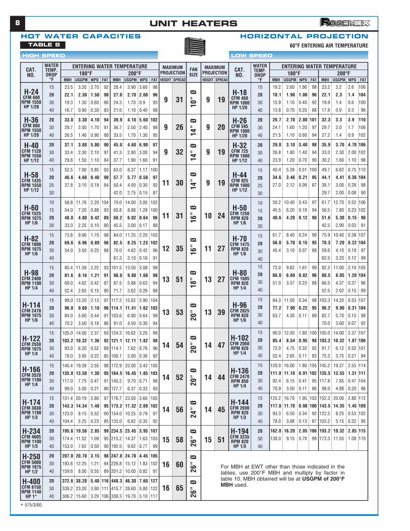
MBH USGPM WPD FAT MBH USGPM WPD FAT HEIGHT SPREAD200°F180°F200°F
MAXIMUMPROJECTION
FANSIZE
HEIGHT SPREAD
MAXIMUMPROJECTION180°F
ENTERING WATER TEMPERATURE ENTERING WATER TEMPERATURE
60°F ENTERING AIR TEMPERATURE
WATERTEMP.DROP
°F
CAT.NO.
H-24CFM 680
RPM 1550HP 1/20
H-36CFM 880
RPM 1550HP 1/20
H-40CFM 1120RPM 1550
HP 1/12
H-58CFM 1435RPM 1550
HP 1/12
H-60CFM 1525RPM 1075
HP 1/6
H-82CFM 1800RPM 1075
HP 1/6
H-98CFM 2400RPM 1100
HP 1/4
H-114CFM 2470RPM 1075
HP 1/6
H-122CFM 2930RPM 1075
HP 1/4
H-166CFM 3520RPM 1100
HP 1/4
H-174CFM 3830RPM 1100
HP 1/3
H-234CFM 4605RPM 1100
HP 1/3
H-250CFM 5000RPM 1075
HP 1/2
H-400CFM 6150RPM 1140
HP 1*
15
20
30
40
20
30
40
20
30
40
15
20
25
30
10
15
20
30
15
20
30
40
15
20
30
40
15
20
30
40
15
20
30
40
15
20
30
40
15
20
30
40
20
30
40
20
30
40
20
30
40
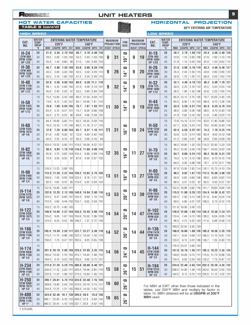
HOT WATER CAPACITIES HORIZONTAL PROJECTION
HIGH SPEED LOW SPEED
19.2 2.60 1.90 98 23.2 3.2 2.6 106
18.1 1.90 1.00 96 22.1 2.3 1.4 104
15.9 1.10 0.40 92 19.9 1.4 0.6 100
13.8 0.70 0.20 88 17.8 0.9 0.3 96
26.7 2.70 2.80 101 32.3 3.3 3.9 110
24.1 1.60 1.20 97 29.7 2.0 1.7 106
21.5 1.10 0.60 94 27.2 1.4 0.9 102
29.8 3.10 3.40 98 35.9 3.70 4.70 106
26.8 1.80 1.40 94 33.0 2.30 2.00 102
23.9 1.20 0.70 90 30.2 1.60 1.10 98
40.4 5.39 0.51 100 49.7 6.62 0.75 110
34.6 3.46 0.21 95 44.1 4.41 0.36 104
27.0 2.12 0.09 87 38.1 3.00 0.28 98
29.7 2.00 0.08 90
50.2 10.40 0.43 97 61.7 12.70 0.52 106
45.5 6.20 0.19 94 56.5 7.80 0.23 102
40.6 4.20 0.12 90 51.6 5.30 0.15 98
42.5 2.90 0.03 91
61.7 8.40 0.24 99 75.9 10.40 0.38 107
56.0 5.70 0.15 95 70.3 7.20 0.22 104
45.4 3.10 0.07 88 59.6 4.10 0.19 97
62.5 3.20 0.12 99
72.0 9.62 1.61 99 82.3 11.00 2.10 105
66.0 6.60 0.82 96 80.5 8.05 1.20 104
51.0 3.37 0.23 88 66.5 4.37 0.37 96
52.5 2.62 0.15 89
84.3 11.50 0.34 98 103.3 14.20 0.53 107
77.2 7.90 0.22 95 96.2 9.90 0.31 104
63.7 4.30 0.11 89 82.7 5.70 0.15 98
70.0 3.60 0.07 92
90.0 12.00 1.80 100 105.0 14.00 2.37 107
85.4 8.54 0.95 98 103.2 10.32 1.87 106
72.0 4.75 0.32 92 91.7 6.12 0.52 101
52.4 2.65 0.11 83 75.3 3.75 0.21 94
120.0 16.00 1.80 105 145.2 19.37 2.55 114
111.0 11.10 0.91 102 135.5 13.55 1.31 111
92.4 6.15 0.41 95 117.8 7.85 0.47 104
70.9 3.50 0.11 86 98.0 4.88 0.20 96
125.2 16.70 1.95 103 152.3 20.00 2.80 112
117.0 11.70 0.98 100 143.5 14.35 1.45 109
93.3 6.50 0.34 92 122.5 8.25 0.53 102
78.0 3.88 0.13 87 103.2 5.15 0.22 95
162.0 16.20 2.05 106 193.2 19.32 2.85 115
138.0 9.15 0.70 99 173.3 11.55 1.08 110
MBH USGPM WPD FAT MBH USGPM WPD FAT
WATERTEMP.DROP
°F
CAT.NO.
H-18CFM 460
RPM 1000HP 1/20
H-26CFM 595
RPM 1000HP 1/20
H-32CFM 725
RPM 1000HP 1/12
H-44CFM 925
RPM 1000HP 1/12
H-50CFM 1250RPM 820HP 1/6
H-70CFM 1475RPM 820HP 1/6
H-80CFM 1685RPM 820HP 1/4
H-96CFM 2025RPM 820HP 1/6
H-102CFM 2060RPM 820HP 1/4
H-136CFM 2470RPM 850HP 1/4
H-144CFM 2690RPM 820HP 1/3
H-194CFM 3235RPM 820HP 1/3
15
20
30
40
20
30
40
20
30
40
15
20
25
30
10
15
20
30
15
20
30
40
15
20
30
40
15
20
30
40
15
20
30
40
15
20
30
40
15
20
30
40
20
30
40
9 31 9 19
9 26 9 20
9 32 9 19
11 30 9 19
11 31 10 24
12 35 11 27
13 51 13 27
13 53 13 39
14 54 14 47
14 52 14 44
14 56 14 45
15 58 15 51
16 60
16 65
10”
Ø14
” Ø
14”
Ø14
” Ø
16”
Ø16
” Ø
18”
Ø20
” Ø
20”
Ø20
” Ø
24”
Ø26
” Ø
26”
Ø26
” Ø
TABLE 8
For MBH at EWT other than those indicated in thetables, use 200°F MBH and multiply by factor intable 10. MBH obtained will be at USGPM of 200°FMBH used.
* 575/3/60.
UNIT HEATERS
10
HIGH SPEED LOW SPEED
39.4 8.00 1.00 109 47.2 9.50 1.40 11834.8 4.75 0.38 103 42.7 5.70 0.54 11332.5 3.25 0.19 100 39.9 3.99 0.28 10927.0 2.25 0.10 93 34.3 2.75 0.14 10224.0 1.65 0.05 90 30.1 2.00 0.08 97
43.4 9.00 1.20 95 53.2 10.50 1.70 10343.2 5.90 0.56 94 50.7 6.70 0.70 10140.0 4.00 0.28 92 49.0 4.90 0.40 9937.2 3.00 0.17 90 45.5 3.70 0.24 9734.2 2.30 0.10 87 42.0 2.75 0.14 9432.0 1.60 0.07 85 40.9 2.10 0.09 93
60.0 12.00 2.10 97 71.7 14.25 3.00 10454.0 7.25 0.85 93 64.7 8.50 1.20 10047.5 4.75 0.38 89 58.8 5.88 0.56 9639.0 2.70 0.14 84 47.3 3.20 0.19 8933.0 1.75 0.06 80 40.3 2.00 0.08 85
76.4 15.40 2.10 99 91.3 18.25 2.90 10772.0 9.70 0.85 97 85.7 11.25 1.10 10467.5 6.75 0.42 95 82.0 8.20 0.62 10258.6 4.00 0.16 90 71.7 4.75 0.22 9754.0 2.50 0.06 87 63.0 3.05 0.10 92
90.9 18.25 2.50 95 108.5 21.50 4.00 10185.2 11.30 1.15 92 100.8 13.25 1.30 9882.0 8.20 0.63 91 95.2 9.52 0.70 9672.0 4.75 0.21 87 87.2 5.90 0.34 9363.0 3.25 0.10 84 77.0 3.80 0.14 89
108.2 22.30 2.60 102 129.5 26.70 3.50 110102.7 14.00 1.20 99 123.5 17.00 1.60 10896.8 9.90 0.65 97 117.8 12.10 0.90 10585.6 5.80 0.32 93 106.7 7.30 0.38 10174.6 3.80 0.09 89 95.7 4.90 0.20 97
117.5 23.50 5.40 94 138.3 27.70 7.00 100109.4 14.60 2.00 92 131.2 17.25 2.70 98103.0 10.30 1.00 90 124.5 12.45 1.50 9689.4 6.00 0.38 86 110.3 7.30 0.54 9275.0 3.75 0.15 82 95.9 4.75 0.23 88
129.0 19.25 2.20 93 152.6 20.20 2.50 99123.0 12.30 1.00 91 147.5 14.75 1.40 97115.8 9.40 0.58 89 141.7 11.50 0.85 96108.0 7.25 0.35 87 133.0 8.85 0.50 9493.0 4.70 0.15 84 117.2 5.75 0.22 90
148.2 19.75 2.80 103 173.2 22.75 3.60 110145.0 14.50 1.50 102 170.0 17.00 2.10 109141.0 11.25 0.95 101 168.0 13.50 1.35 109133.4 9.00 0.60 99 162.7 10.75 0.85 107114.0 5.75 0.25 93 144.9 7.25 0.42 102
171.0 22.75 3.60 97 203.0 26.75 5.00 104165.0 16.50 2.00 96 195.0 19.50 2.60 102159.0 12.80 1.20 95 189.0 15.25 1.70 101154.5 10.25 0.80 94 185.5 12.25 1.10 100138.0 7.00 0.38 90 171.5 8.50 0.54 97
200.0 20.00 2.80 91 238.0 23.80 3.80 96192.0 16.00 1.80 89 232.7 18.75 2.50 96190.6 12.75 1.20 89 228.2 15.25 1.60 95175.4 8.75 0.56 87 215.0 10.75 0.85 93
294.0 29.40 3.60 96 350.0 35.00 5.20 103282.0 22.50 2.00 94 340.2 27.50 3.20 101265.4 17.75 1.40 92 325.5 21.75 2.00 100238.6 12.00 0.65 89 294.0 14.60 0.95 96
420.0 42.00 5.00 95 511.0 51.10 7.50 103396.0 31.50 3.00 93 485.1 39.50 4.50 101358.6 24.50 1.70 90 456.7 30.50 2.80 98319.4 16.00 0.65 87 408.8 20.40 1.20 94
MBH USGPM WPD FAT MBH USGPM WPD FAT HEIGHT SPREAD
200°F180°F200°FMAXIMUM*PROJECTION FAN
SIZEHEIGHT SPREAD
MAXIMUM*PROJECTION180°F
ENTERING WATER TEMPERATURE ENTERING WATER TEMPERATUREWATERTEMP.DROP
°F
CAT.NO.
V-40CFM 750
RPM 1550HP 1/30
V-48CFM 1150RPM 1550
HP 1/12
V-66CFM 1500RPM 1725
HP 1/4
V-84CFM 1435RPM 1100
HP 1/6
V-96CFM 2425RPM 1725
HP 1/4
V-106CFM 2400RPM 1075
HP 1/4
V-130CFM 3200RPM 1075
HP 1/4
V-140CFM 3660RPM 1100
HP 1/2
V-180CFM 3200RPM 1100
HP 1/2
V-200CFM 4250RPM 1100
HP 1/2
V-252CFM 6000RPM 1075
HP 3/4
V-370CFM 7600RPM 1075
HP 3/4
V-520CFM 11100RPM 1100
HP 2
1015202530
101520253040
1015203040
1015203040
1015203040
1015203040
1015203040
1520253040
1520253040
1520253040
20253040
20253040
20253040
33.0 6.65 0.52 120 40.0 7.80 0.95 13227.6 3.75 0.25 110 34.3 4.50 0.35 12223.0 2.30 0.10 102 29.4 2.94 0.16 11318.0 1.50 0.05 93 24.5 2.00 0.08 10416.4 1.00 0.02 90 21.0 1.30 0.04 98
36.6 7.45 0.85 103 43.4 8.55 1.10 11133.6 4.55 0.35 100 40.3 5.25 0.65 10832.5 3.25 0.19 98 38.8 3.88 0.26 10627.0 2.25 0.09 92 34.3 2.75 0.14 10024.0 1.65 0.06 88 30.1 2.00 0.08 96
48.0 9.50 1.40 106 57.4 11.40 2.05 11542.0 5.50 0.70 100 50.7 6.75 0.73 10836.0 3.60 0.23 94 48.8 4.88 0.40 10731.4 2.50 0.12 90 33.6 2.40 0.11 9224.0 1.20 0.03 83 31.5 1.50 0.05 90
66.0 13.25 1.50 106 78.7 15.70 2.10 11461.4 8.25 0.60 102 73.5 9.85 1.90 11157.5 5.75 0.30 100 70.0 7.00 0.45 10848.0 3.25 0.10 93 59.5 4.00 0.16 10142.0 2.00 0.04 89 52.5 2.55 0.07 96
73.2 14.60 1.90 103 86.8 17.25 2.60 11169.0 9.25 0.80 101 81.9 10.75 1.10 10865.0 6.50 0.40 98 79.0 7.90 0.58 10754.0 3.60 0.13 92 68.3 4.50 0.20 10049.2 2.50 0.06 89 59.5 3.00 0.09 95
84.0 16.90 2.60 103 100.0 20.00 3.70 11279.2 10.60 1.10 101 94.5 12.45 1.50 10970.0 7.00 0.50 96 87.5 8.75 0.75 10554.0 3.70 0.15 88 68.3 4.50 0.21 9542.0 2.20 0.06 81 54.6 2.75 0.09 88
108.2 22.20 2.60 102 128.9 26.60 3.50 110102.2 14.00 1.20 100 123.0 16.90 1.60 10896.4 9.90 0.65 97 117.3 12.10 0.90 10585.2 5.80 0.32 93 106.2 7.30 0.38 10174.3 3.80 0.09 89 95.3 4.90 0.23 97
109.4 14.60 1.35 97 129.5 17.00 1.80 103104.0 10.40 0.70 95 124.5 12.45 1.00 10294.8 7.75 0.40 92 119.0 9.50 0.60 10087.0 6.00 0.25 89 110.3 7.30 0.36 9773.4 3.75 0.10 85 95.9 4.75 0.15 92
127.2 17.00 2.10 111 148.7 19.75 2.80 119123.6 12.36 1.15 109 145.2 14.52 1.50 118114.0 9.25 0.65 105 138.6 11.25 0.95 115105.0 7.10 0.40 102 130.2 8.70 0.58 11288.4 4.50 0.16 95 112.7 5.60 0.24 105
145.4 19.30 2.60 102 172.2 22.75 3.60 110140.0 14.00 1.45 101 167.5 16.75 2.10 109135.0 10.75 0.85 99 161.0 13.00 1.30 107127.2 8.50 0.55 97 155.4 10.25 0.80 105110.4 5.50 0.24 92 145.2 7.25 0.40 102
171.0 17.10 2.10 96 202.5 20.25 2.70 103166.6 13.50 1.30 95 197.7 16.00 1.80 102160.4 10.75 0.85 94 192.5 12.75 1.20 101150.0 7.50 0.42 92 178.5 8.80 0.44 98
247.5 24.75 2.60 101 297.5 29.75 4.00 110232.4 18.75 1.50 99 285.2 23.00 2.30 108219.0 14.60 0.95 97 267.7 17.85 1.40 105196.4 9.90 0.42 93 241.5 12.00 0.62 100
MBH USGPM WPD FAT MBH USGPM WPD FAT
WATERTEMP.DROP
°F
CAT.NO.
V-30CFM 510
RPM 1000HP 1/30
V-38CFM 780
RPM 1000HP 1/12
V-50CFM 955
RPM 1075HP 1/4
V-70CFM 1340RPM 820HP 1/6
V-80CFM 1545RPM 1075
HP 1/4
V-90CFM 1790RPM 850HP 1/4
V-108CFM 2380RPM 850HP 1/4
V-124CFM 2730RPM 820HP 1/2
V-144CFM 2380RPM 820HP 1/2
V-170CFM 3160RPM 820HP 1/2
V-204CFM 4470RPM 820HP 3/4
V-300CFM 5660RPM 820HP 3/4
1015202530
101520253040
1015203040
1015203040
1015203040
1015203040
1015203040
1520253040
1520253040
1520253040
20253040
20253040
12 28 12 22
14 35 12 29
15 46 14 40
18 58 15 35
18 58 17 44
20 55 17 44
18 60 15 46
20 55 17 44
14 31 12 31
18 35 18 31
26 69 22 45
35 68 25 51
45 85
12”
Ø14
” Ø
14”
Ø16
” Ø
16”
Ø18
” Ø
18”
Ø20
” Ø
20”
Ø24
” Ø
24”
Ø30
” Ø
30”
Ø
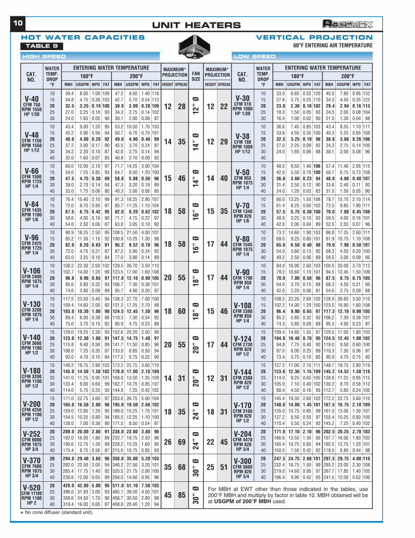
HOT WATER CAPACITIES VERTICAL PROJECTIONTABLE 9
* No cone diffuser (standard unit).
60°F ENTERING AIR TEMPERATURE
For MBH at EWT other than those indicated in the tables, use200°F MBH and multiply by factor in table 10. MBH obtained will beat USGPM of 200°F MBH used.
UNIT HEATERS
11
54.1 10.00 1.50 127 63.0 11.50 2.80 13752.8 6.75 0.65 125 60.0 8.00 1.00 13447.5 4.75 0.38 118 55.0 5.50 0.70 12841.9 3.30 0.20 112 52.5 4.00 0.28 12437.9 2.50 0.12 107 49.0 3.25 0.19 120
62.1 11.00 1.80 110 70.2 12.60 2.30 11660.0 7.75 0.95 108 67.5 9.00 1.20 11459.0 5.90 0.80 107 65.0 6.50 0.70 11253.9 4.25 0.32 103 63.0 5.00 0.42 11052.0 3.50 0.22 102 60.0 4.00 0.28 10845.6 2.30 0.10 97 54.0 2.75 0.15 103
81.9 15.00 3.20 110 96.3 17.30 4.20 11978.1 10.25 1.60 108 90.0 12.00 2.10 11572.5 7.25 0.85 105 82.5 8.25 1.00 11158.4 4.00 0.28 96 71.2 4.75 0.38 10452.0 2.70 0.14 92 61.2 3.10 0.19 97
105.9 19.15 3.00 114 121.5 22.00 4.20 122100.0 13.25 1.50 111 115.5 15.40 2.10 12097.0 9.70 0.85 110 110.0 11.00 1.20 11785.9 5.75 0.32 104 101.2 6.75 0.42 11278.1 4.00 0.16 100 92.2 4.65 0.21 107
125.6 22.60 4.20 108 144.0 26.00 5.40 116118.4 15.70 2.20 105 136.9 18.25 2.50 112113.0 11.30 1.15 103 130.0 13.00 1.50 110104.0 7.00 0.45 100 123.0 8.20 0.63 10796.0 4.75 0.21 97 112.5 5.75 0.32 103
134.4 24.40 5.40 112 153.9 28.00 7.00 120129.9 17.25 2.80 110 150.0 20.00 3.80 118125.0 12.50 1.50 108 141.0 14.10 1.90 114108.8 7.25 0.54 102 131.2 8.75 0.75 11189.9 4.50 0.22 95 110.2 5.50 0.30 102
159.2 28.75 7.10 106 180.9 33.00 9.50 112153.9 20.30 3.70 105 176.2 23.50 5.40 111146.0 14.60 2.00 102 167.5 16.75 2.60 108132.0 8.75 0.75 98 154.5 10.30 1.00 105119.2 6.00 0.38 94 141.8 6.10 0.40 101
180.0 23.50 3.60 106 203.4 27.00 4.40 111172.5 17.25 1.90 104 196.2 19.62 2.40 110165.6 13.25 1.10 102 191.2 15.25 1.50 108160.0 10.75 0.75 100 184.5 12.30 1.00 107144.0 7.25 0.34 96 171.0 8.50 0.48 103
200.0 26.50 5.00 118 229.5 30.50 6.00 126197.5 19.75 2.80 117 220.0 22.00 3.40 124193.9 15.50 1.70 116 218.5 17.50 2.20 123190.4 12.75 1.20 115 217.5 14.50 1.50 122177.9 9.00 0.60 111 207.0 10.50 0.85 120
236.0 31.50 6.50 111227.5 22.75 3.60 110 260.0 26.00 5.00 117220.0 17.70 2.20 108 252.0 20.25 3.00 115216.0 14.50 1.50 107 247.5 16.50 2.00 114206.0 10.25 0.80 105 237.6 12.00 1.10 112
275.0 27.50 5.40 102 315.0 31.50 7.00 108269.9 21.55 3.40 101 307.8 24.60 4.20 107264.0 17.70 2.30 100 300.0 20.00 2.80 106254.1 12.75 1.20 99 292.5 14.75 1.50 105
402.5 40.25 6.50 109396.0 31.70 4.60 108 468.0 36.00 5.80 117385.6 25.70 2.90 107 441.0 29.40 3.60 114353.9 17.75 1.40 103 415.8 16.75 1.30 111
602.5 60.25 10.50 111572.0 46.00 6.00 108 661.5 53.00 8.00 116544.0 36.15 3.80 106 630.0 42.00 5.00 113478.1 24.50 1.70 100 580.5 29.10 2.50 109
MBH USGPM WPD FAT MBH USGPM WPD FAT HEIGHT SPREAD
240°F220°F240°FMAXIMUM*PROJECTION FAN
SIZEHEIGHT SPREAD
MAXIMUM*PROJECTION220°F
ENTERING WATER TEMPERATURE ENTERING WATER TEMPERATUREWATERTEMP.DROP
°F
CAT.NO.
V-40CFM 750
RPM 1550HP 1/30
V-48CFM 1150RPM 1550HP 1/12
V-66CFM 1500RPM 1725
HP 1/4
V-84CFM 1435RPM 1100
HP 1/6
V-96CFM 2425RPM 1725
HP 1/4
V-106CFM 2400RPM 1075
HP 1/4
V-130CFM 3200RPM 1075
HP 1/4
V-140CFM 3660RPM 1100
HP 1/2
V-180CFM 3200RPM 1100
HP 1/2
V-200CFM 4250RPM 1100
HP 1/2
V-252CFM 6000RPM 1075
HP 3/4
V-370CFM 7600RPM 1075
HP 3/4
V-520CFM 11100RPM 1100
HP 2
1015202530
101520253040
1015203040
1015203040
1015203040
1015203040
1015203040
1520253040
1520253040
1520253040
20253040
20253040
20253040
45.6 8.25 1.05 143 57.6 9.50 1.40 16441.9 5.50 0.50 136 49.9 6.65 0.52 15037.5 3.75 0.25 128 44.0 4.40 0.34 14030.4 2.40 0.10 115 38.2 3.00 0.17 12927.2 1.75 0.06 109 34.5 2.30 0.10 123
49.9 9.00 1.30 119 57.6 10.25 1.60 12848.0 6.25 0.62 117 55.9 7.45 0.85 12645.5 4.55 0.36 114 51.5 5.15 0.48 12141.9 3.30 0.20 109 49.5 4.00 0.28 11937.9 2.50 0.15 105 48.7 3.25 0.19 11832.0 1.65 0.06 98 39.6 2.00 0.08 107
42.0 5.50 0.70 100 50.7 6.75 0.73 10861.6 8.00 1.00 119 72.0 9.50 1.40 12955.0 5.50 0.70 113 67.0 6.70 0.70 12444.0 3.10 0.18 102 54.0 3.60 0.23 11241.9 2.50 0.12 100 46.8 2.25 0.10 105
89.9 16.25 2.20 122 103.5 18.75 3.00 13185.9 11.40 1.15 119 99.4 13.25 1.50 12782.5 8.25 0.60 117 94.5 9.45 0.80 12572.0 4.80 0.22 110 86.2 5.75 0.30 11964.0 3.25 0.10 104 76.5 3.80 0.14 113
100.0 18.25 2.50 119 114.6 21.00 3.80 12896.0 12.70 1.40 117 109.8 14.60 1.90 12592.0 9.25 0.80 114 105.0 10.50 1.00 12281.9 5.50 0.30 108 97.5 6.50 0.40 11872.0 3.60 0.13 102 87.3 4.50 0.20 111
116.0 20.90 4.00 120 132.3 24.00 5.00 128110.1 14.50 2.00 117 126.7 16.90 2.60 125106.0 10.60 1.10 115 120.0 12.00 1.40 12285.9 5.75 0.34 104 105.0 7.00 0.50 11472.0 3.70 0.15 97 87.8 4.50 0.22 105
134.4 24.40 5.40 112 153.9 28.00 7.00 120129.9 17.25 2.80 110 150.0 20.00 3.80 118125.0 12.50 1.50 108 141.0 14.10 1.90 114108.8 7.25 0.54 102 131.2 8.75 0.75 11189.9 4.50 0.22 95 110.2 5.50 0.30 102
152.0 20.00 2.50 111 173.2 23.00 3.20 118146.0 14.60 1.35 109 165.0 16.50 1.70 115140.0 11.25 0.85 107 162.0 12.90 1.10 114132.0 8.75 0.50 104 156.0 10.40 0.70 112116.0 6.00 0.25 99 138.6 7.00 0.32 106
172.0 22.75 3.60 131 196.2 26.00 4.80 138170.0 17.00 2.10 128 191.5 19.15 2.70 136164.0 13.25 1.30 125 189.0 15.00 1.60 135156.0 10.50 0.85 122 185.4 12.36 1.15 134140.0 7.10 0.40 116 166.5 8.30 0.52 126
201.9 26.75 5.00 119 232.2 30.75 7.00 128193.0 19.30 2.60 116 220.0 22.00 3.40 124188.0 15.00 1.60 115 214.2 17.25 2.20 123182.4 12.25 1.10 113 210.0 14.00 1.40 121169.6 8.50 0.55 110 198.0 10.00 0.75 118
236.0 23.60 4.00 110 267.5 26.75 5.00 117229.6 18.35 2.50 109 261.9 21.00 3.20 116225.6 15.00 1.60 108 256.7 17.10 2.10 114213.8 10.75 0.85 105 245.7 12.40 1.20 112
345.0 34.50 5.20 118336.0 27.00 3.20 116 384.7 30.75 4.20 124320.0 21.30 1.90 114 371.2 24.75 2.60 122292.0 14.60 0.95 109 342.0 17.25 1.30 117
MBH USGPM WPD FAT MBH USGPM WPD FAT
WATERTEMP.DROP
°F
CAT.NO.
V-30CFM 510
RPM 1000HP 1/30
V-38CFM 780
RPM 1000HP 1/12
V-50CFM 955
RPM 1075HP 1/4
V-70CFM 1340RPM 820HP 1/6
V-80CFM 1545RPM 1075
HP 1/4
V-90CFM 1790RPM 850HP 1/4
V-108CFM 2380RPM 850HP 1/4
V-124CFM 2730RPM 820HP 1/2
V-144CFM 2380RPM 820HP 1/2
V-170CFM 3160RPM 820HP 1/2
V-204CFM 4470RPM 820HP 3/4
V-300CFM 5660RPM 820HP 3/4
1015202530
101520253040
1015203040
1015203040
1015203040
1015203040
1015203040
1520253040
1520253040
1520253040
20253040
20253040
12 28 12 22
14 35 12 29
15 46 14 40
18 58 15 35
18 58 17 44
20 55 17 44
18 60 15 46
20 55 17 44
14 31 12 31
18 35 18 31
26 69 22 45
35 68 25 51
45 85
12”
Ø14
” Ø
14”
Ø16
” Ø
16”
Ø18
” Ø
18”
Ø20
” Ø
20”
Ø24
” Ø
24”
Ø30
” Ø
30”
Ø
HIGH SPEED LOW SPEED
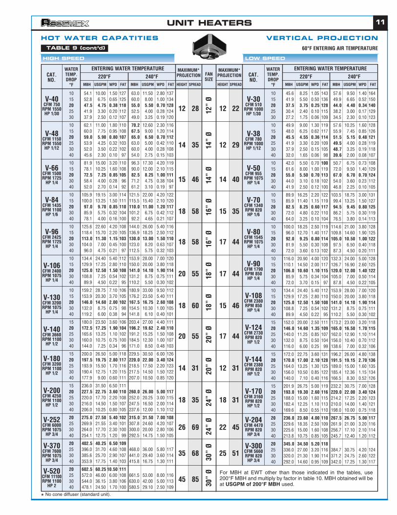
HOT WATER CAPATITIES VERTICAL PROJECTIONTABLE 9 (cont’d)
* No cone diffuser (standard unit).
60°F ENTERING AIR TEMPERATURE
For MBH at EWT other than those indicated in the tables, use200°F MBH and multiply by factor in table 10. MBH obtained will beat USGPM of 200°F MBH used.
UNIT HEATERS
12
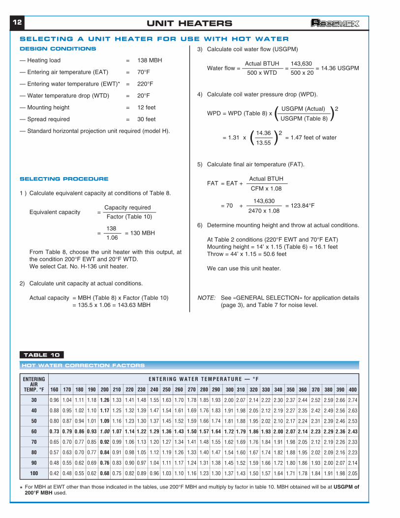
SELECTING A UNIT HEATER FOR USE WITH HOT WATERDESIGN CONDITIONS
— Heating load = 138 MBH
— Entering air temperature (EAT) = 70°F
— Entering water temperature (EWT)* = 220°F
— Water temperature drop (WTD) = 20°F
— Mounting height = 12 feet
— Spread required = 30 feet
— Standard horizontal projection unit required (model H).
SELECTING PROCEDURE
1 ) Calculate equivalent capacity at conditions of Table 8.
Capacity requiredEquivalent capacity = —————————
Factor (Table 10)
138 = ——— = 130 MBH
1.06
From Table 8, choose the unit heater with this output, atthe condition 200°F EWT and 20°F WTD.We select Cat. No. H-136 unit heater.
2) Calculate unit capacity at actual conditions.
Actual capacity = MBH (Table 8) x Factor (Table 10)= 135.5 x 1.06 = 143.63 MBH
3) Calculate coil water flow (USGPM)
Actual BTUH 143,630Water flow = ——————— = ———— = 14.36 USGPM
500 x WTD 500 x 20
4) Calculate coil water pressure drop (WPD).
USGPM (Actual) WPD = WPD (Table 8) x —————————
USGPM (Table 8)
14.36= 1.31 x ——— = 1.47 feet of water
13.55
5) Calculate final air temperature (FAT).
Actual BTUHFAT = EAT + ———————
CFM x 1.08
143,630 = 70 + —————— = 123.84°F
2470 x 1.08
6) Determine mounting height and throw at actual conditions.
At Table 2 conditions (220°F EWT and 70°F EAT)Mounting height = 14’ x 1.15 (Table 6) = 16.1 feetThrow = 44’ x 1.15 = 50.6 feet
We can use this unit heater.
NOTE: See «GENERAL SELECTION» for application details(page 3), and Table 7 for noise level.
( )2
( )2
E N T E R I N G W A T E R T E M P E R A T U R E — ° F
160 170 180 190 200 210 220 230 240 250 260 270 280 290
30 0.96 1.04 1.11 1.18 1.26 1.33 1.41 1.48 1.55 1.63 1.70 1.78 1.85 1.93
40 0.88 0.95 1.02 1.10 1.17 1.25 1.32 1.39 1.47 1.54 1.61 1.69 1.76 1.83
50 0.80 0.87 0.94 1.01 1.09 1.16 1.23 1.30 1.37 1.45 1.52 1.59 1.66 1.74
60 0.73 0.79 0.86 0.93 1.00 1.07 1.14 1.22 1.29 1.36 1.43 1.50 1.57 1.64
70 0.65 0.70 0.77 0.85 0.92 0.99 1.06 1.13 1.20 1.27 1.34 1.41 1.48 1.55
80 0.57 0.63 0.70 0.77 0.84 0.91 0.98 1.05 1.12 1.19 1.26 1.33 1.40 1.47
90 0.48 0.55 0.62 0.69 0.76 0.83 0.90 0.97 1.04 1.11 1.17 1.24 1.31 1.38
100 0.42 0.48 0.55 0.62 0.68 0.75 0.82 0.89 0.96 1.03 1.10 1.16 1.23 1.30
300 310 320 330 340 350 360 370 380 390 400
2.00 2.07 2.14 2.22 2.30 2.37 2.44 2.52 2.59 2.66 2.74
1.91 1.98 2.05 2.12 2.19 2.27 2.35 2.42 2.49 2.56 2.63
1.81 1.88 1.95 2.02 2.10 2.17 2.24 2.31 2.39 2.46 2.53
1.72 1.79 1.86 1.93 2.00 2.07 2.14 2.23 2.29 2.36 2.43
1.62 1.69 1.76 1.84 1.91 1.98 2.05 2.12 2.19 2.26 2.33
1.54 1.60 1.67 1.74 1.82 1.88 1.95 2.02 2.09 2.16 2.23
1.45 1.52 1.59 1.66 1.72 1.80 1.86 1.93 2.00 2.07 2.14
1.37 1.43 1.50 1.57 1.64 1.71 1.78 1.84 1.91 1.98 2.05
ENTERINGAIR
TEMP. °F
HOT WATER CORRECTION FACTORS
TABLE 10
* For MBH at EWT other than those indicated in the tables, use 200°F MBH and multiply by factor in table 10. MBH obtained will be at USGPM of200°F MBH used.
UNIT HEATERS
13
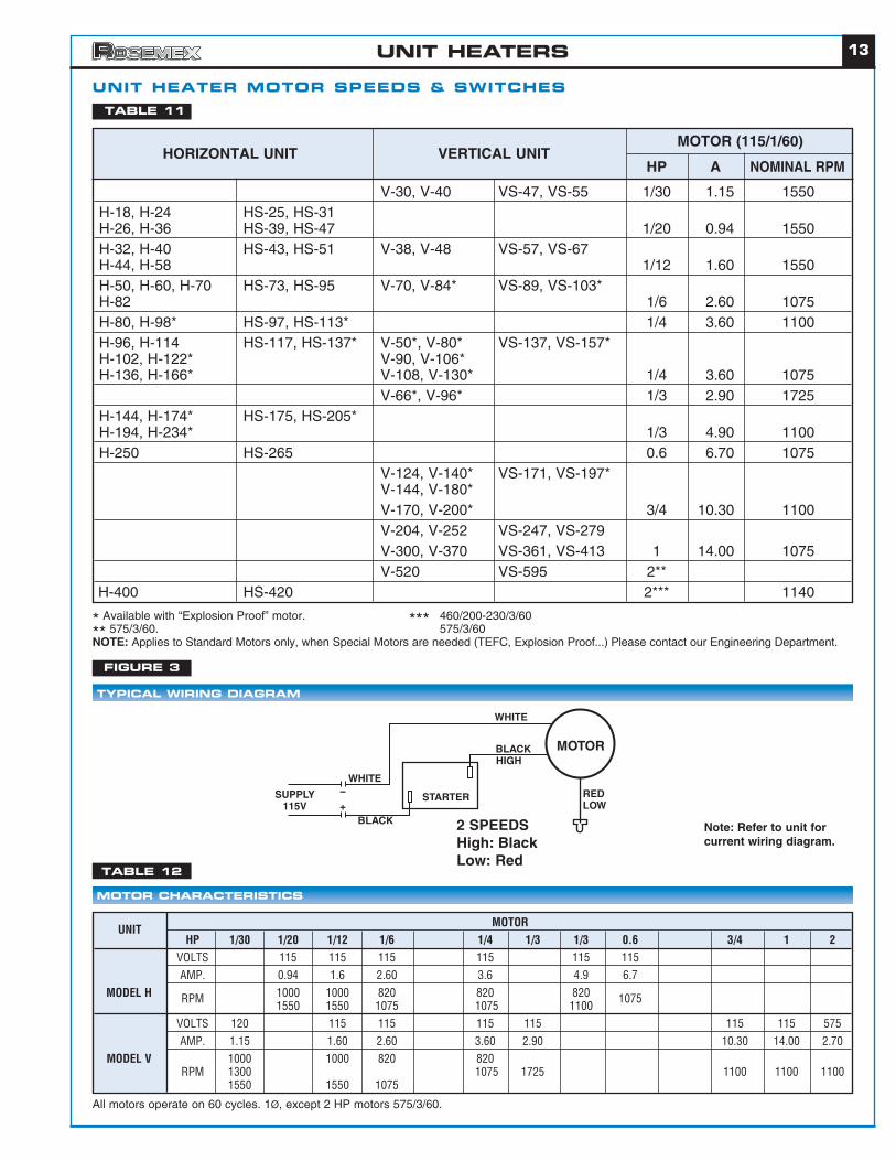
UNIT HEATER MOTOR SPEEDS & SWITCHES
HP 1/30 1/20 1/12 1/6 1/4 1/3 1/3 0.6 3/4 1 2VOLTS 115 115 115 115 115 115AMP. 0.94 1.6 2.60 3.6 4.9 6.7
MODEL H RPM 1000 1000 820 820 820 10751550 1550 1075 1075 1100
VOLTS 120 115 115 115 115 115 115 575AMP. 1.15 1.60 2.60 3.60 2.90 10.30 14.00 2.70
MODEL V 1000 1000 820 820RPM 1300 1075 1725 1100 1100 1100
1550 1550 1075
MOTOR CHARACTERISTICS
TYPICAL WIRING DIAGRAM
TABLE 11
TABLE 12
HORIZONTAL UNIT VERTICAL UNITMOTOR (115/1/60)
HP A NOMINAL RPM
V-30, V-40 VS-47, VS-55 1/30 1.15 1550H-18, H-24 HS-25, HS-31H-26, H-36 HS-39, HS-47 1/20 0.94 1550H-32, H-40 HS-43, HS-51 V-38, V-48 VS-57, VS-67H-44, H-58 1/12 1.60 1550H-50, H-60, H-70 HS-73, HS-95 V-70, V-84* VS-89, VS-103*H-82 1/6 2.60 1075H-80, H-98* HS-97, HS-113* 1/4 3.60 1100H-96, H-114 HS-117, HS-137* V-50*, V-80* VS-137, VS-157*H-102, H-122* V-90, V-106*H-136, H-166* V-108, V-130* 1/4 3.60 1075
V-66*, V-96* 1/3 2.90 1725H-144, H-174* HS-175, HS-205*H-194, H-234* 1/3 4.90 1100H-250 HS-265 0.6 6.70 1075
V-124, V-140* VS-171, VS-197*V-144, V-180*V-170, V-200* 3/4 10.30 1100V-204, V-252 VS-247, VS-279V-300, V-370 VS-361, VS-413 1 14.00 1075V-520 VS-595 2**
H-400 HS-420 2*** 1140
All motors operate on 60 cycles. 1Ø, except 2 HP motors 575/3/60.
* Available with “Explosion Proof” motor. *** 460/200-230/3/60
** 575/3/60. 575/3/60NOTE: Applies to Standard Motors only, when Special Motors are needed (TEFC, Explosion Proof...) Please contact our Engineering Department.
UNITMOTOR
FIGURE 3
MOTOR
REDLOW
WHITE
WHITE
BLACK
BLACK
HIGH
STARTERSUPPLY115V
--
+
2 SPEEDSHigh: BlackLow: Red
Note: Refer to unit forcurrent wiring diagram.
UNIT HEATERS
14
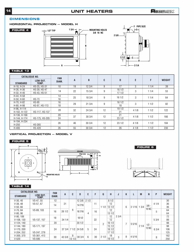
DIMENSIONS
E
CD
3 1/4
3 1/2
2 5/8
F PIPE SIZEMOUNTING HOLES
3/8 16 NC1 3/41/2" TYP
A
B
HORIZONTAL PROJECTION — MODEL H
VERTICAL PROJECTION — MODEL V
FIGURE 4
FIGURE 6
FIGURE 5
TABLE 13
TABLE 14
L
F
M
A
A
F
MOUNTING HOLESN
J
M
C
LGPipe sizeK min
D
E
H
CEILING
P
LOW OUT. A C D E F G H J K L M N P WEIGHTSTANDARD TEMP.V-30, 40 VS-47, 55 12 12 3/8 2 1/2 8 1/2 30V-38, 48 VS-57, 67 21 11 12 4 1/4 36V-50, 66 1 1/2 13 1/2 36V-70, 84 VS-89, 103 12 64V-80, 96 13 1/2 64V-90, 106 12 72V-108, 130 VS-137, 157 34 1/4 22 12 5 3/4 89V-124, 140 20 20 1/2 16 1/2 98V-144, 180 VS-171, 197 15 1/2 98V-170, 200 24 37 3/4 7 1/2 24 5/8 5 24 16 1/2 106V-204, 252 VS-247, 279 17 1/2 125V-300, 370 VS-361, 413 18 162V-520 VS-595 19 1/2 250
14
16
18
30 43 5/8 913 1/2
30 3/4 6 30
2
2 1/2 3
6
7
8
3 1/16
5 5/16
4 5/16
1 3/4
2 1/4
3/8 -16 NC
1/2 -13 NC
26 1/2 64
14 7/16
16 7/16
18 1/2
16
2 3/4
5
6 3/4
8
CATALOGUE NO. FANDIAM.
LOW OUT. A B C D E F WEIGHTSTANDARD TEMP.
H-18, H-24 HS-25, HS-31 10 19 12 3/4 9 17 3 1 1/4 39H-26, H-36 HS-39, HS-47 16 1/2H-32, H-40 HS-43, HS-51 17 1/2H-44, H-58 14H-50, H-60 HS-73 16H-70, H-82 HS-95 16 16 1/2H-80, H-98 HS-97, HS-113 18 18H-96, H-114 19 1/2H-102, H-122 HS-117, HS-137 21H-136, H-166 20 21H-144, H-174 HS-175, HS-205 24 23 1/2H-194, H-234
26 46 30 3/4 12 23 1/2 4 1/8 1 1/2 184H-250 HS-265H-400 HS-420 26 55 30 3/4 12 26 4 1/8 1 1/2 230
14
20
22
25
29
32
37
15 3/4
18 3/4
21 3/4
24 3/4
30 3/4
9
9
9
12
12
3
3
3
4 1/8
4 1/8
1 1/4
1 1/4
1 1/2
1 1/2
1 1/2
53
64
82
122
166
16 1/2
CATALOGUE NO.FAN
DIAM.
UNIT HEATERS
15
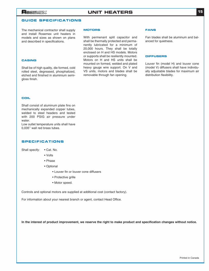
GUIDE SPECIFICATIONS
SPECIFICATIONS
The mechanical contractor shall supplyand install Rosemex unit heaters inmodels and sizes as shown on plansand described in specifications.
CASING
Shall be of high quality, die formed, coldrolled steel, degreased, phosphatized,etched and finished in aluminium semi-gloss finish.
COIL
Shall consist of aluminum plate fins onmechanically expanded copper tubes,welded to steel headers and testedwith 200 PSIG air pressure underwater.Low outlet temperature units shall have0,035’’ wall red brass tubes.
MOTORS
With permenant split capacitor andshall be thermally protected and perma-nently lubricated for a minimum of20,000 hours. They shall be totallyenclosed on H and HS models. Motorsor supports shall be resiliently mounted.Motors on H and HS units shall bemounted on formed, welded and platedheavy gauge wire support. On V andVS units, motors and blades shall beremovable through fan opening.
FANS
Fan blades shall be aluminum and bal-anced for quietness.
DIFFUSERS
Louver fin (model H) and louver cone(model V) diffusers shall have individu-ally adjustable blades for maximum airdistribution flexibility.
Shall specify: • Cat. No.
• Volts
• Phase
• Optional
• Louver fin or louver cone diffusers
• Protective grille
• Motor speed.
Controls and optional motors are supplied at additional cost (contact factory).
For information about your nearest branch or agent, contact Head Office.
In the interest of product improvement, we reserve the right to make product and specification changes without notice.
Printed in Canada
UNIT HEATERS

MECAR METAL
1560, Marie-Victorin blvdSaint-Bruno (Quebec)J3V 6B9Tel.: (450) 653-1002Fax: (450) 653-3464
Products
http://www.rosemex.com