Embed Size (px)
Citation preview

Unit Workbook 2 - Level 5 ENG – U64 Thermofluids © 2020 UniCourse Ltd. All Rights Reserved
Page 1 of 26
Pearson BTEC Level 5 Higher Nationals in Engineering (RQF)
Unit 64: Thermofluids
Unit Workbook 2 in a series of 4 for this unit
Learning Outcome 2
Vapour Power Cycles
Sample
Unit Workbook 2 - Level 5 ENG – U64 Thermofluids © 2020 UniCourse Ltd. All Rights Reserved
Page 2 of 26
Contents INTRODUCTION .................................................................................................................................................. 3
GUIDANCE .......................................................................................................................................................... 3
2.1 Power Cycles ........................................................................................................................................... 4
2.1.1 The Brayton Cycle ............................................................................................................................ 4
2.1.2 Second Law of Thermodynamics with Heat Engines ....................................................................... 4
2.1.3 Carnot Cycle ..................................................................................................................................... 4
2.1.3 Vapour Cycles .................................................................................................................................. 6
2.1.4 Whole Plant Efficiency ..................................................................................................................... 7
2.1.4.1 Ideal Boiler ................................................................................................................................ 8
2.1.4.2 Real Boiler ................................................................................................................................. 8
2.2 Two-Phase Fluids Through the Carnot Cycle .......................................................................................... 9
2.2.1 Carnot Cycle Issues .......................................................................................................................... 9
2.3 Rankine Cycle ........................................................................................................................................ 10
2.3.1 The Ideal Rankine Cycle ................................................................................................................. 10
2.3.2 Real Rankine Cycles ....................................................................................................................... 10
2.4 Improving the Rankine Cycle................................................................................................................. 13
2.4.1 Lowering Condenser Pressure ....................................................................................................... 13
2.4.2 Increasing Boiler Pressure ............................................................................................................. 14
3.4.3 Superheating .................................................................................................................................. 15
3.4.3 Reheating ....................................................................................................................................... 16
3.4.4 Feed Water Regeneration .............................................................................................................. 18
3.5 Combined Cycle Gas Turbines ............................................................................................................... 21
Sample
Unit Workbook 2 - Level 5 ENG – U64 Thermofluids © 2020 UniCourse Ltd. All Rights Reserved
Page 3 of 26
Purpose
Theory
Question
Challenge
Example
Video
INTRODUCTION Examine the operation of practical steam and gas turbines plants
• Steam and gas turbine plant:
o Principles of operation of steam and gas turbine plants.
o Use of property diagrams to analyse plant.
o Characteristics of steam/gas turbine plant as used in energy supply.
o Energy-saving options adopted on steam plants operating on modified Rankine cycle.
o Performance characteristics of steam and gas power plant.
o Cycle efficiencies: turbine isentropic efficiencies and overall relative efficiency.
GUIDANCE This document is prepared to break the unit material down into bite size chunks. You will see the learning
outcomes above treated in their own sections. Therein you will encounter the following structures;
Explains why you need to study the current section of material. Quite often learners
are put off by material which does not initially seem to be relevant to a topic or
profession. Once you understand the importance of new learning or theory you will
embrace the concepts more readily.
Conveys new material to you in a straightforward fashion. To support the treatments
in this section you are strongly advised to follow the given hyperlinks, which may be
useful documents or applications on the web.
The examples/worked examples are presented in a knowledge-building order. Make
sure you follow them all through. If you are feeling confident then you might like to
treat an example as a question, in which case cover it up and have a go yourself. Many
of the examples given resemble assignment questions which will come your way, so
follow them through diligently.
Questions should not be avoided if you are determined to learn. Please do take the
time to tackle each of the given questions, in the order in which they are presented.
The order is important, as further knowledge and confidence is built upon previous
knowledge and confidence. As an Online Learner it is important that the answers to
questions are immediately available to you. Contact your Unit Tutor if you need help.
You can really cement your new knowledge by undertaking the challenges. A challenge
could be to download software and perform an exercise. An alternative challenge
might involve a practical activity or other form of research.
Videos on the web can be very useful supplements to your distance learning efforts.
Wherever an online video(s) will help you then it will be hyperlinked at the appropriate
point.
Sample
Unit Workbook 2 - Level 5 ENG – U64 Thermofluids © 2020 UniCourse Ltd. All Rights Reserved
Page 4 of 26
2.1 Power Cycles 2.1.1 The Brayton Cycle So far, the only power cycle discussed has been the Brayton cycle, which usually considers that the working
fluid moving through the system is a gas, and that it does not go through any phase change. In this workbook,
power cycles that use a liquid will be analysed, and because of the high temperatures, these liquids will likely
involve a phase change.
2.1.2 Second Law of Thermodynamics with Heat Engines The second law of thermodynamics is a series of observations that concerns the way things flow as time
progresses forward. Typical observations are “water flows from high to low”, and “heat flows from hot to
cold”. In the context of heat engines, however, the second law can be summed up as: “No heat engine can
be 100% efficient”.
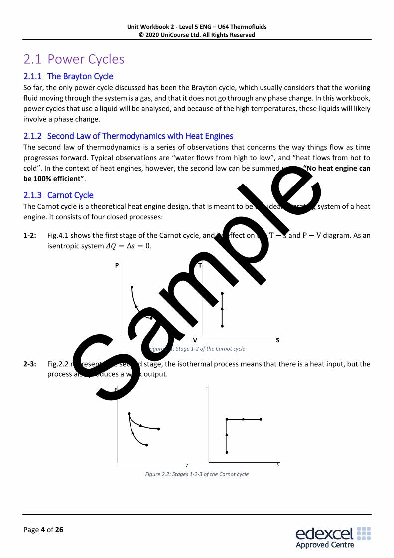
2.1.3 Carnot Cycle The Carnot cycle is a theoretical heat engine design, that is meant to be the ideal operating system of a heat
engine. It consists of four closed processes:
1-2: Fig.4.1 shows the first stage of the Carnot cycle, and its effect on the T − s and P − V diagram. As an
isentropic system 𝛥𝑄 = Δ𝑠 = 0.
Figure 2.1: Stage 1-2 of the Carnot cycle
2-3: Fig.2.2 represents the second stage, the isothermal process means that there is a heat input, but the
process also produces a work output.
Figure 2.2: Stages 1-2-3 of the Carnot cycle
Sample
Unit Workbook 2 - Level 5 ENG – U64 Thermofluids © 2020 UniCourse Ltd. All Rights Reserved
Page 5 of 26
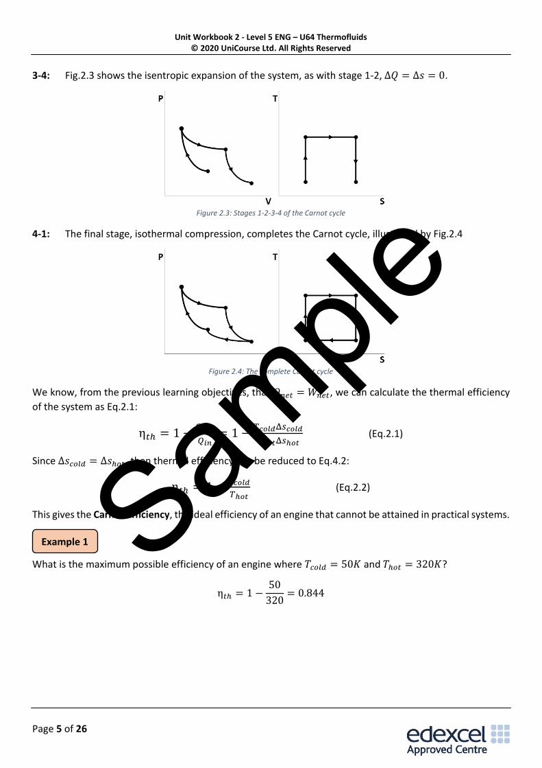
3-4: Fig.2.3 shows the isentropic expansion of the system, as with stage 1-2, Δ𝑄 = Δ𝑠 = 0.
Figure 2.3: Stages 1-2-3-4 of the Carnot cycle
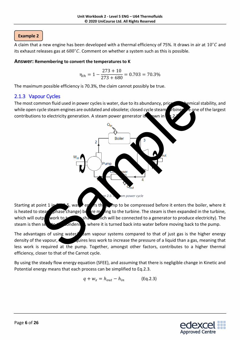
4-1: The final stage, isothermal compression, completes the Carnot cycle, illustrated by Fig.2.4
Figure 2.4: The complete Carnot cycle
We know, from the previous learning objectives, that 𝑄𝑛𝑒𝑡 = 𝑊𝑛𝑒𝑡, we can calculate the thermal efficiency
of the system as Eq.2.1:
η𝑡ℎ = 1 −𝑄𝑜𝑢𝑡
𝑄𝑖𝑛= 1 −
𝑇𝑐𝑜𝑙𝑑Δ𝑠𝑐𝑜𝑙𝑑
𝑇ℎ𝑜𝑡Δ𝑠ℎ𝑜𝑡 (Eq.2.1)
Since Δ𝑠𝑐𝑜𝑙𝑑 = Δ𝑠ℎ𝑜𝑡, then thermal efficiency can be reduced to Eq.4.2:
η𝑡ℎ = 1 −𝑇𝑐𝑜𝑙𝑑
𝑇ℎ𝑜𝑡 (Eq.2.2)
This gives the Carnot efficiency, the ideal efficiency of an engine that cannot be attained in practical systems.
What is the maximum possible efficiency of an engine where 𝑇𝑐𝑜𝑙𝑑 = 50𝐾 and 𝑇ℎ𝑜𝑡 = 320𝐾?
η𝑡ℎ = 1 −50
320= 0.844
Example 1 Sample
Unit Workbook 2 - Level 5 ENG – U64 Thermofluids © 2020 UniCourse Ltd. All Rights Reserved
Page 6 of 26
A claim that a new engine has been developed with a thermal efficiency of 75%. It draws in air at 10∘𝐶 and
its exhaust releases gas at 680∘𝐶. Comment on whether a system such as this is possible.
Answer: Remembering to convert the temperatures to K
η𝑡ℎ = 1 −273 + 10
273 + 680= 0.703 = 70.3%
The maximum possible efficiency is 70.3%, the claim cannot possibly be true.
2.1.3 Vapour Cycles The most common fluid used in power cycles is water, due to its abundancy, price and chemical stability, and
while open cycle steam engines are outdated and obsolete; closed cycle steam turbines are one of the largest
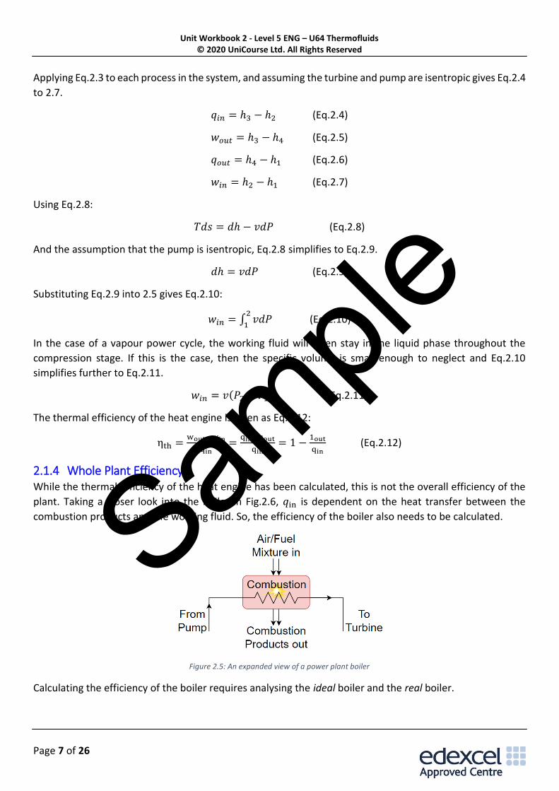
contributions to electricity generation. A steam power generator is shown in Fig.2.5.
Figure 2.5: A steam power cycle
Starting at point 1 in Fig.2.5, water enters the pump to be compressed before it enters the boiler, where it
is heated to steam (phase change) before moving to the turbine. The steam is then expanded in the turbine,
which will output work to turn the shaft (which will be connected to a generator to produce electricity). The
steam is then sent to the condenser, where it is turned back into water before moving back to the pump.
The advantages of using water/steam vapour systems compared to that of just gas is the higher energy
density of the vapour, it also requires less work to increase the pressure of a liquid than a gas, meaning that
less work is required at the pump. Together, amongst other factors, contributes to a higher thermal
efficiency, closer to that of the Carnot cycle.
By using the steady flow energy equation (SFEE), and assuming that there is negligible change in Kinetic and
Potential energy means that each process can be simplified to Eq.2.3.
𝑞 + 𝑤𝑥 = ℎ𝑜𝑢𝑡 − ℎ𝑖𝑛 (Eq.2.3)
Example 2
Sample
Unit Workbook 2 - Level 5 ENG – U64 Thermofluids © 2020 UniCourse Ltd. All Rights Reserved
Page 7 of 26
Applying Eq.2.3 to each process in the system, and assuming the turbine and pump are isentropic gives Eq.2.4
to 2.7.
𝑞𝑖𝑛 = ℎ3 − ℎ2 (Eq.2.4)
𝑤𝑜𝑢𝑡 = ℎ3 − ℎ4 (Eq.2.5)
𝑞𝑜𝑢𝑡 = ℎ4 − ℎ1 (Eq.2.6)
𝑤𝑖𝑛 = ℎ2 − ℎ1 (Eq.2.7)
Using Eq.2.8:
𝑇𝑑𝑠 = 𝑑ℎ − 𝑣𝑑𝑃 (Eq.2.8)
And the assumption that the pump is isentropic, Eq.2.8 simplifies to Eq.2.9.
𝑑ℎ = 𝑣𝑑𝑃 (Eq.2.9)
Substituting Eq.2.9 into 2.5 gives Eq.2.10:
𝑤𝑖𝑛 = ∫ 𝑣𝑑𝑃2
1 (Eq.2.10)
In the case of a vapour power cycle, the working fluid will often stay in the liquid phase throughout the
compression stage. If this is the case, then the specific volume is small enough to neglect and Eq.2.10
simplifies further to Eq.2.11.
𝑤𝑖𝑛 = 𝑣(𝑃2 − 𝑃1) (Eq.2.11)
The thermal efficiency of the heat engine is given as Eq.2.12:
ηth =wout−win
qin=
qin−qout
qin= 1 −
1out
qin (Eq.2.12)
2.1.4 Whole Plant Efficiency While the thermal efficiency of the heat engine has been calculated, this is not the overall efficiency of the
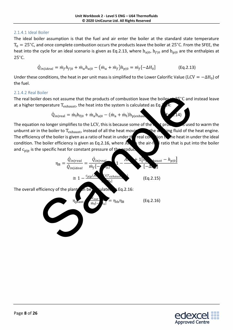
plant. Taking a closer look into the boiler in Fig.2.6, 𝑞in is dependent on the heat transfer between the
combustion products and the working fluid. So, the efficiency of the boiler also needs to be calculated.
Figure 2.5: An expanded view of a power plant boiler
Calculating the efficiency of the boiler requires analysing the ideal boiler and the real boiler.
Sample
Unit Workbook 2 - Level 5 ENG – U64 Thermofluids © 2020 UniCourse Ltd. All Rights Reserved
Page 8 of 26
2.1.4.1 Ideal Boiler
The ideal boiler assumption is that the fuel and air enter the boiler at the standard state temperature
T0 = 25∘C, and once complete combustion occurs the products leave the boiler at 25∘C. From the SFEE, the
heat into the cycle for an ideal scenario is given as Eq.2.13, where ha|0, h𝑓|0 and hp|0 are the enthalpies at
25∘C.
��𝑖𝑛|𝑖𝑑𝑒𝑎𝑙 = ��𝑓ℎ𝑓|0 + ��𝑎ℎ𝑎|0 − (��𝑎 + ��𝑓)ℎ𝑝|0 = 𝑚𝑓 [−Δ𝐻0] (Eq.2.13)
Under these conditions, the heat in per unit mass is simplified to the Lower Calorific Value (LCV = −ΔH0) of
the fuel.
2.1.4.2 Real Boiler
The real boiler does not assume that the products of combustion leave the boiler at 25∘C and instead leave
at a higher temperature Texhaust, the heat into the system is calculated as Eq.2.14:
Qin|real = mfhf|0 + maha|0 − (ma + mf)hp|exhaust (Eq.2.14)
The equation no longer simplifies to the LCV, this is because some of the heat produced is used to warm the
unburnt air in the boiler to Texhaust, instead of all the heat moving into the working fluid of the heat engine.
The efficiency of the boiler is given as a ratio of heat in under the real condition to the heat in under the ideal
condition. The boiler efficiency is given as Eq.2.16, where AFR is the air-fuel ratio that is put into the boiler
and cp|p is the specific heat for constant pressure of the products.
ηB =��𝑖𝑛|𝑟𝑒𝑎𝑙
��𝑖𝑛|𝑖𝑑𝑒𝑎𝑙
=��𝑖𝑛|𝑟𝑒𝑎𝑙
��𝑓[−∆𝐻0]= 1 −
𝐴𝐹𝑅 + 1[ℎ𝑝|𝑒𝑥ℎ𝑎𝑢𝑠𝑡 − ℎ𝑝|0]
[−∆𝐻0]
≅ 1 −𝑐𝑝|𝑝(𝐴𝐹𝑅+1)(𝑇𝑒𝑥ℎ𝑎𝑢𝑠𝑡−𝑇0)
[−∆𝐻0] (Eq.2.15)
The overall efficiency of the plant can be calculated as Eq.2.16:
ηplant =Wout−Win
mf[−ΔH0]= ηthηB (Eq.2.16)
Sample