Embed Size (px)
Citation preview

UNIT-4 TESTING AND IMPLEMENTATION
SOFTWARE TESTING FUNDAMENTALS
Definition For Testing:
Software testing is a process of executing a program or application with the intent of
finding the software bugs. It can also be stated as the process of validating and
verifying that a software program or application or product.
Testing Fundamental
Software engineer attempts to build software from an abstract concept to a
tangible product. Next is Testing.
The engineer creates a series of test cases that are intended to "demolish" the
software that has been built.
In fact, testing is the one step in the software process that could be viewed as
destructive rather than constructive.
Testing Principles
All tests should be traceable to customer requirements.
Tests should be planned long before testing begins.
The Pareto principle applies to software testing.
Testing should begin “in the small” and progress toward testing “in the large.”
Exhaustive testing is not possible.
To be most effective, testing should be conducted by an independent third party.
Software Testability
S/w testability is simply how easily system or program or product can be tested.
Testing must exhibit set of characteristics that achieve the goal of finding errors
with a minimum of effort.
Characteristics of s/w Testability:
o Operability - “The better it works, the more efficiently it can be tested”
o Relatively few bugs will block the execution of tests.
o Allowing testing progress without fits and starts o Observability - “What you see is what you test. “
o Distinct output is generated for each input.
o System states and variables are visible or queriable during execution.
o Incorrect output is easily identified.
o Internal errors are automatically detected & reported.
o Source code is accessible.
o Controllability - "The better we can control the software, the more the testing
can be automated and optimized”
o Software and hardware states and variables can be controlled directly by
the test engineer.
o Tests can be conveniently specified, automated, and reproduced. o Decomposability - By controlling the scope of testing, we can more quickly
isolate problems and perform smarter retesting.
o Independent modules can be tested independently.
o Simplicity - The less there is to test, the more quickly we can test it."
o Functional simplicity (e.g., the feature set is the minimum necessary to meet
requirements).
o Structural simplicity (e.g., architecture is modularized to limit the
propagation of faults).
o Code simplicity (e.g., a coding standard is adopted for ease of inspection
and maintenance).
o Stability - "The fewer the changes, the fewer the disruptions to testing."
o Changes to the software are infrequent.
o Changes to the software are controlled.
o Changes to the software do not invalidate existing tests.
o Understandability – "The more information we have, the smarter we will test."
o Dependencies between internal, external, and shared components are well
understood.
o Changes to the design are communicated to testers.
o Technical documentation is instantly accessible, well organized, specific
and detailed, and accurate.
Testing attributes:
1. A good test has a high probability of finding an error.
Tester must understand the software and attempt to develop a mental
picture of how the software might fail.
2. A good test is not redundant.
Testing time and resources are limited.
There is no point in conducting a test that has the same purpose as
another test.
Every test should have a different purpose
Ex. Valid/ invalid password.
3. A good test should be “best of breed”
In a group of tests that have a similar intent, time and resource limitations
may mitigate toward the execution of only a subset of these tests.
4. A good test should be neither too simple nor too complex.
sometimes possible to combine a series of tests into one test case, the
possible side effects associated with this approach may mask errors.
Each test should be executed separately
INTERNAL AND EXTERNAL VIEWS OF TESTING:
Objectives of testing is to finding the most errors with a minimum amount of
time and effort.
Test case design methods provide a mechanism that can help to ensure the
completeness of tests and provide the highest likelihood for uncovering errors in
software.
Any product or system can be tested on two ways:
1. Knowing the specified function that a product has been designed to perform;
tests can be conducted that demonstrate each function is fully operational while
at the same time searching for errors in each function
The first test approach takes an external view is called Black Box testing
2. knowing the internal workings of a product, tests can be conducted to ensure
that "all gears mesh," that is, internal operations are performed according to
specifications and all internal components have been effectively exercised.
The second requires an internal view is called White box testing.
White box testing
White-box testing of software is predicated on close examination of procedural
detail.
Logical paths through the software are tested by providing test cases that
exercise specific sets of conditions and/or loops.
The "status of the program" may be examined at various points.
White-box testing, sometimes called glass-box testing, is a test case design method
that uses the control structure of the procedural design to derive test cases.
Using this method, SE can derive test cases that
1. Guarantee that all independent paths within a module have been exercised at
least once
2. Exercise all logical decisions on their true and false sides,
3. Execute all loops at their boundaries and within their operational bounds
4. Exercise internal data structures to ensure their validity.
Basis path testing
Basis path testing is a white-box testing technique
To derive a logical complexity measure of a procedural design.
Test cases derived to exercise the basis set are guaranteed to execute every
statement in the program at least one time.
Methods:
1. Flow graph notation
2. Independent program paths or Cyclomatic complexity
3. Deriving test cases
4. Graph Matrices
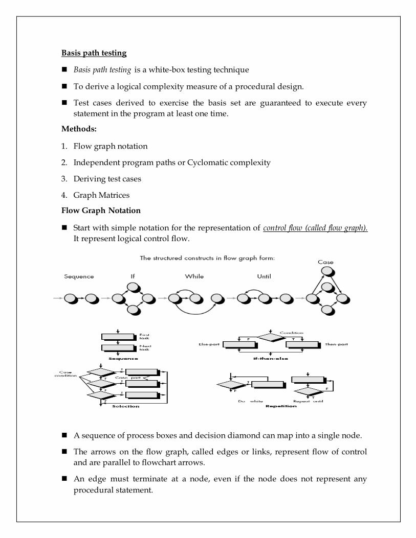
Flow Graph Notation
Start with simple notation for the representation of control flow (called flow graph).
It represent logical control flow.
A sequence of process boxes and decision diamond can map into a single node.
The arrows on the flow graph, called edges or links, represent flow of control
and are parallel to flowchart arrows.
An edge must terminate at a node, even if the node does not represent any
procedural statement.

Areas bounded by edges and nodes are called regions. When counting regions,
we include the are outside the graph as a region.
When compound condition are encountered in procedural design, flow graph
becomes slightly more complicated.
When we translating PDL segment into flow graph, separate node is created for
each condition.
Each node that contains a condition is called predicate node and is characterized
by two or more edges comes from it.
Independent program paths or Cyclomatic complexity
An independent path is any path through the program that introduces at least one
new set of processing statement or new condition.
For example, a set of independent paths for flow graph:
Path 1: 1-11
Path 2: 1-2-3-4-5-10-1-11 Basis Set
Path 3: 1-2-3-6-8-9-1-11
Path 4: 1-2-3-6-7-9-1-11
Note that each new path introduces a new edge.
The path 1-2-3-4-5-10-1-2-3-6-8-9-1-11 is not considered to e an independent path
because it is simply a combination of already specified paths and does not
traverse any new edges.
Test cases should be designed to force execution of these paths (basis set).
Every statement in the program should be executed at least once and every
condition will have been executed on its true and false.
How do we know how many paths to looks for?
Cyclomatic complexity is a software metrics that provides a quantitative measure
of the logical complexity of a program.

It defines no. of independent paths in the basis set and also provides number of
test that must be conducted.
One of three ways to compute cyclomatic complexity:
The no. of regions corresponds to the cyclomatic complexity.
Cyclomatic complexity, V(G), for a flow graph, G, is defined as
V(G) = E - N + 2
E is the number of flow graph edges, N is the number of flow graph nodes.
Cyclomatic complexity, V(G), for a flow graph, G, is also defined as
V(G) = P + 1
where P is the number of predicate nodes edges
So the value of V(G) provides us with upper bound of test cases.
Deriving Test Cases
It is a series of steps method.
The procedure average depicted in PDL.
Average, an extremely simple algorithm, contains compound conditions and
loops.
To derive basis set, follow the steps.
1. Using the design or code as a foundation, draw a corresponding flow graph.
A flow graph is created by numbering those PDL statements that
will be mapped into corresponding flow graph nodes.
2. Determine the cyclomatic complexity of the resultant flow graph. V(G) can be
determined without developing a flow graph by counting all conditional
statements in the PDL (for the procedure average, compound conditions count as
two) and adding 1
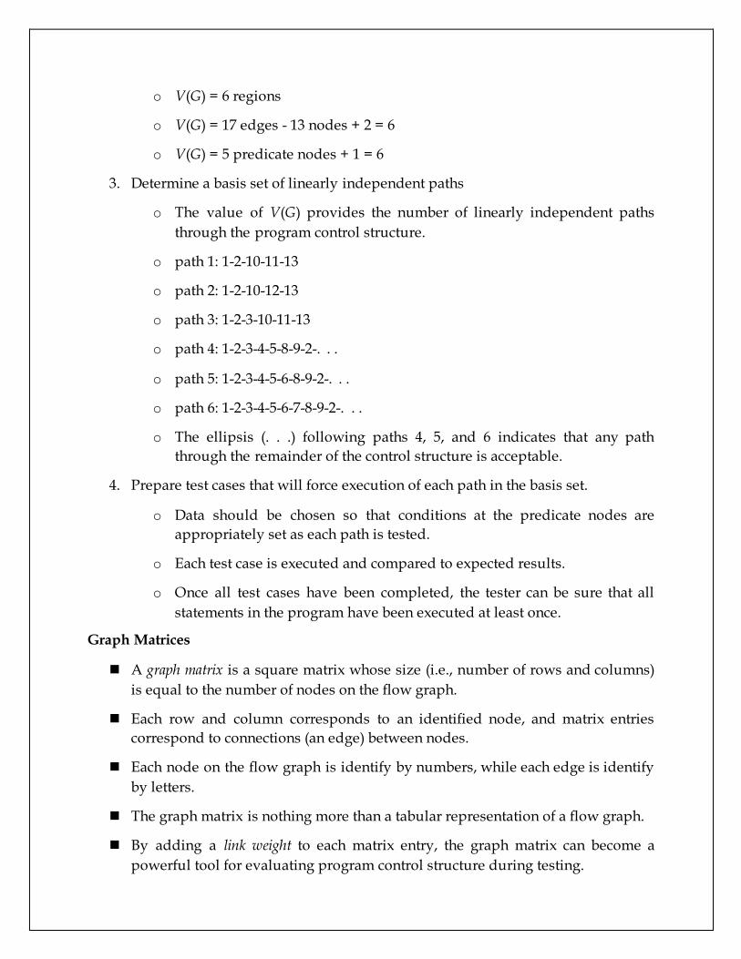
o V(G) = 6 regions
o V(G) = 17 edges - 13 nodes + 2 = 6
o V(G) = 5 predicate nodes + 1 = 6
3. Determine a basis set of linearly independent paths
o The value of V(G) provides the number of linearly independent paths
through the program control structure.
o path 1: 1-2-10-11-13
o path 2: 1-2-10-12-13
o path 3: 1-2-3-10-11-13
o path 4: 1-2-3-4-5-8-9-2-. . .
o path 5: 1-2-3-4-5-6-8-9-2-. . .
o path 6: 1-2-3-4-5-6-7-8-9-2-. . .
o The ellipsis (. . .) following paths 4, 5, and 6 indicates that any path
through the remainder of the control structure is acceptable.
4. Prepare test cases that will force execution of each path in the basis set.
o Data should be chosen so that conditions at the predicate nodes are
appropriately set as each path is tested.
o Each test case is executed and compared to expected results.
o Once all test cases have been completed, the tester can be sure that all
statements in the program have been executed at least once.
Graph Matrices
A graph matrix is a square matrix whose size (i.e., number of rows and columns)
is equal to the number of nodes on the flow graph.
Each row and column corresponds to an identified node, and matrix entries
correspond to connections (an edge) between nodes.
Each node on the flow graph is identify by numbers, while each edge is identify
by letters.
The graph matrix is nothing more than a tabular representation of a flow graph.
By adding a link weight to each matrix entry, the graph matrix can become a
powerful tool for evaluating program control structure during testing.
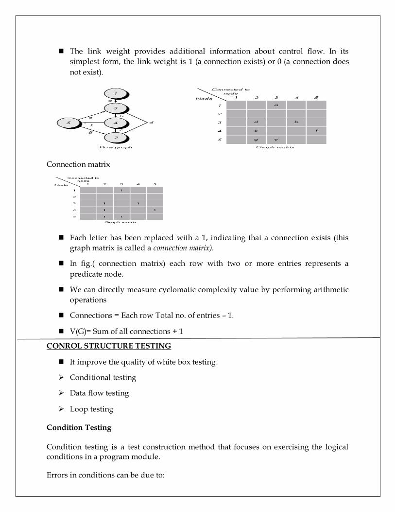
The link weight provides additional information about control flow. In its
simplest form, the link weight is 1 (a connection exists) or 0 (a connection does
not exist).
Connection matrix
Each letter has been replaced with a 1, indicating that a connection exists (this
graph matrix is called a connection matrix).
In fig.( connection matrix) each row with two or more entries represents a
predicate node.
We can directly measure cyclomatic complexity value by performing arithmetic
operations
Connections = Each row Total no. of entries – 1.
V(G)= Sum of all connections + 1
CONROL STRUCTURE TESTING
It improve the quality of white box testing.
Conditional testing
Data flow testing
Loop testing
Condition Testing
Condition testing is a test construction method that focuses on exercising the logical conditions in a program module.
Errors in conditions can be due to:
Boolean operator error Boolean variable error Boolean parenthesis error Relational operator error Arithmetic expression error
definition: "For a compound condition C, the true and false branches of C and every simple condition in C need to be executed at least once." Multiple-condition testing requires that all true-false combinations of simple conditions be exercised at least once. Therefore, all statements, branches, and conditions are necessarily covered.
Data flow testing
Selects test paths according to the location of definitions and use of variables. This is a somewhat sophisticated technique and is not practical for extensive use. Its use should be targeted to modules with nested if and loop statements
Loop Testing
• A white-box testing technique that focuses exclusively on the validity of loop constructs
• Four different classes of loops exist – Simple loops – Nested loops – Concatenated loops – Unstructured loops
• Testing occurs by varying the loop boundary values – Examples:
for(i=0;i<MAX_INDEX;i++) while (currentTemp >= MINIMUM_TEMPERATURE)
Testing of Simple Loops
1) Skip the loop entirely 2) Only one pass through the loop 3) Two passes through the loop 4) m passes through the loop, where m < n 5) n –1, n, n + 1 passes through the loop
Testing of Nested Loops
1) Start at the innermost loop; set all other loops to minimum values 2) Conduct simple loop tests for the innermost loop while holding the outer loops
at their minimum iteration parameter values; add other tests for out-of-range or excluded values

3) Work outward, conducting tests for the next loop, but keeping all other outer loops at minimum values and other nested loops to “typical” values
4) Continue until all loops have been tested
Testing of Concatenated Loops
• For independent loops, use the same approach as for simple loops • Otherwise, use the approach applied for nested loops
Testing of Unstructured Loops
• Redesign the code to reflect the use of structured programming practices • Depending on the resultant design, apply testing for simple loops, nested loops,
or concatenated loops
Black box testing
Also called behavioral testing, focuses on the functional requirements of the software.
It enables the software engineer to derive sets of input conditions that will fully exercise all functional requirements for a program.
Black-box testing is not an alternative to white-box techniques but it is complementary approach.
Black-box testing attempts to find errors in the following categories: Incorrect or missing functions, Interface errors, Errors in data structures or external data base access. Behavior or performance errors, Initialization and termination errors.
Black-box testing purposely ignored control structure, attention is focused on the information domain. Tests are designed to answer the following questions:
How is functional validity tested? How is system behavior and performance tested? What classes of input will make good test cases?
By applying black-box techniques, we derive a set of test cases that satisfy the following criteria
Test cases that reduce the number of additional test cases that must be designed to achieve reasonable testing (i.e minimize effort and time)
Test cases that tell us something about the presence or absence of classes of errors
Black box testing methods Graph-Based Testing Methods Equivalence partitioning Boundary value analysis (BVA) Orthogonal Array Testing

Graph-Based Testing Methods
To understand the objects that are modeled in software and the relationships that connect these objects.
Next step is to define a series of tests that verify “all objects have the expected relationship to one another.
Stated in other way: Create a graph of important objects and their relationships Develop a series of tests that will cover the graph
So that each object and relationship is exercised and errors are uncovered. Begin by creating graph –
a collection of nodes that represent objects links that represent the relationships between objects node weights that describe the properties of a node link weights that describe some characteristic of a link.
Nodes are represented as circles connected by links that take a number of different forms.
A directed link (represented by an arrow) indicates that a relationship moves in only one direction.
A bidirectional link, also called a symmetric link, implies that the relationship applies in both directions.
Parallel links are used when a number of different relationships are established between graph nodes.
Object #1 = new file menu select Object #2 = document window Object #3 = document text
Referring to example figure, a menu select on new file generates a document window.
The link weight indicates that the window must be generated in less than 1.0 second.
The node weight of document window provides a list of the window attributes that are to be expected when the window is generated.
An undirected link establishes a symmetric relationship between the new file menu select and document text,
parallel links indicate relationships between document window and document text
Number of behavioral testing methods that can make use of graphs: Transaction flow modeling.
The nodes represent steps in some transaction and the links represent the logical connection between steps
Finite state modeling. The nodes represent different user observable states of the software and
the links represent the transitions that occur to move from state to state. (Starting point and ending point)
Data flow modeling. The nodes are data objects and the links are the transformations that occur
to translate one data object into another. Timing modeling.
The nodes are program objects and the links are the sequential connections between those objects.
Link weights are used to specify the required execution times as the program executes.
Equivalence Partitioning
Equivalence partitioning is a black-box testing method that divides the input domain of a program into classes of data from which test cases can be derived.
Test case design for equivalence partitioning is based on an evaluation of equivalence classes for an input condition.
An equivalence class represents a set of valid or invalid states for input conditions. Typically, an input condition is either a specific numeric value, a range of values,
a set of related values, or a Boolean condition.
To define equivalence classes follow the guideline
1. If an input condition specifies a range, one valid and two invalid equivalence classes are defined.

2. If an input condition requires a specific value, one valid and two invalid equivalence classes are defined.
3. If an input condition specifies a member of a set, one valid and one invalid equivalence class are defined.
4. If an input condition is Boolean, one valid and one invalid class are defined.
Example
area code—blank or three-digit number prefix—three-digit number not beginning with 0 or 1 suffix—four-digit number password—six digit alphanumeric string commands— check, deposit, bill pay, and the like area code:
Input condition, Boolean—the area code may or may not be present. Input condition, value— three digit number
prefix: Input condition, range—values defined between 200 and 999, with specific
exceptions. Suffix:
Input condition, value—four-digit length password:
Input condition, Boolean—a password may or may not be present. Input condition, value—six-character string.
command: Input condition, set— check, deposit, bill pay.
Boundary Value Analysis (BVA)
Boundary value analysis is a test case design technique that complements equivalence partitioning.
Rather than selecting any element of an equivalence class, BVA leads to the selection of test cases at the "edges" of the class.
In other word, Rather than focusing solely on input conditions, BVA derives test cases from the output domain as well.
Guidelines for BVA
1. If an input condition specifies a range bounded by values a and b, test cases should be designed with values a and b and just above and just below a and b.
2. If an input condition specifies a number of values, test cases should be developed that exercise the minimum and maximum numbers. Values just above and below minimum and maximum are also tested.
3. Apply guidelines 1 and 2 to output conditions. 4. If internal program data structures have prescribed boundaries be certain to
design a test case to exercise the data structure at its boundary
Orthogonal Array Testing
The number of input parameters is small and the values that each of the parameters may take are clearly bounded.
When these numbers are very small (e.g., three input parameters taking on three discrete values each), it is possible to consider every input permutation .
However, as the number of input values grows and the number of discrete values for each data item increases (exhaustive testing occurs)
Orthogonal array testing can be applied to problems in which the input domain is relatively small but too large to accommodate exhaustive testing.
Orthogonal Array Testing can be used to reduce the number of combinations and provide maximum coverage with a minimum number of test cases.
Example
Consider the send function for a fax application. Four parameters, P1, P2, P3, and P4, are passed to the send function. Each takes
on three discrete values. P1 takes on values:
P1 = 1, send it now P1 = 2, send it one hour later P1 = 3, send it after midnight
P2, P3, and P4 would also take on values of 1, 2 and 3, signifying other send functions.
OAT is an array of values in which each column represents a Parameter - value that can take a certain set of values called levels.
Each row represents a test case. Parameters are combined pair-wise rather than representing all possible
combinations of parameters and levels
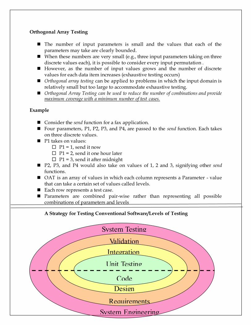
A Strategy for Testing Conventional Software/Levels of Testing
Code
Design
Requirements
System Engineering
Unit Testing
Integration Testing
Validation
Testing
System Testing

Regression Testing
• Each new addition or change to baselined software may cause problems with functions that previously worked flawlessly
• Regression testing re-executes a small subset of tests that have already been conducted
– Ensures that changes have not propagated unintended side effects – Helps to ensure that changes do not introduce unintended behavior or
additional errors – May be done manually or through the use of automated capture/playback
tools • Regression test suite contains three different classes of test cases
– A representative sample of tests that will exercise all software functions – Additional tests that focus on software functions that are likely to be
affected by the change – Tests that focus on the actual software components that have been
changed
Unit testing
– Concentrates on each component/function of the software as implemented in the source code
– Exercises specific paths in a component's control structure to ensure complete coverage and maximum error detection
– Components are then assembled and integrated – Focuses testing on the function or software module – Concentrates on the internal processing logic and data structures – Is simplified when a module is designed with high cohesion – Reduces the number of test cases – Allows errors to be more easily predicted and uncovered – Concentrates on critical modules and those with high cyclomatic
complexity when testing resources are limited
Targets for Unit Test Cases
• Module interface – Ensure that information flows properly into and out of the module
• Local data structures – Ensure that data stored temporarily maintains its integrity during all steps
in an algorithm execution • Boundary conditions
– Ensure that the module operates properly at boundary values established to limit or restrict processing
• Independent paths (basis paths) – Paths are exercised to ensure that all statements in a module have been
executed at least once
• Error handling paths – Ensure that the algorithms respond correctly to specific error conditions
Common Computational Errors in Execution Paths
• Misunderstood or incorrect arithmetic precedence • Mixed mode operations (e.g., int, float, char) • Incorrect initialization of values • Precision inaccuracy and round-off errors • Incorrect symbolic representation of an expression (int vs. float)
Other Errors to Uncover
• Comparison of different data types • Incorrect logical operators or precedence • Expectation of equality when precision error makes equality unlikely (using ==
with float types) • Incorrect comparison of variables • Improper or nonexistent loop termination • Failure to exit when divergent iteration is encountered • Improperly modified loop variables • Boundary value violations
Problems to uncover in Error Handling
• Error description is unintelligible or ambiguous • Error noted does not correspond to error encountered • Error condition causes operating system intervention prior to error handling • Exception condition processing is incorrect • Error description does not provide enough information to assist in the location of
the cause of the error
Drivers and Stubs for Unit Testing
• Driver – A simple main program that accepts test case data, passes such data to the
component being tested, and prints the returned results • Stubs
– Serve to replace modules that are subordinate to (called by) the component to be tested
– It uses the module’s exact interface, may do minimal data manipulation, provides verification of entry, and returns control to the module undergoing testing
• Drivers and stubs both represent overhead – Both must be written but don’t constitute part of the installed software
product
Integration Testing
• Defined as a systematic technique for constructing the software architecture – At the same time integration is occurring, conduct tests to uncover errors
associated with interfaces • Objective is to take unit tested modules and build a program structure based on
the prescribed design • Two Approaches
– Non-incremental Integration Testing – Incremental Integration Testing
Non-incremental Integration Testing
• Commonly called the “Big Bang” approach • All components are combined in advance • The entire program is tested as a whole • Chaos results • Many seemingly-unrelated errors are encountered • Correction is difficult because isolation of causes is complicated • Once a set of errors are corrected, more errors occur, and testing appears to enter
an endless loop
Incremental Integration Testing
• Three kinds – Top-down integration – Bottom-up integration – Sandwich integration
• The program is constructed and tested in small increments • Errors are easier to isolate and correct • Interfaces are more likely to be tested completely • A systematic test approach is applied
Top-down Integration
• Modules are integrated by moving downward through the control hierarchy, beginning with the main module
• Subordinate modules are incorporated in either a depth-first or breadth-first fashion
– DF: All modules on a major control path are integrated – BF: All modules directly subordinate at each level are integrated
• Advantages
– This approach verifies major control or decision points early in the test process
• Disadvantages

– Stubs need to be created to substitute for modules that have not been built or tested yet; this code is later discarded
– Because stubs are used to replace lower level modules, no significant data flow can occur until much later in the integration/testing process
Bottom-up Integration
• Integration and testing starts with the most atomic modules in the control hierarchy
• Advantages
– This approach verifies low-level data processing early in the testing process
– Need for stubs is eliminated • Disadvantages
– Driver modules need to be built to test the lower-level modules; this code is later discarded or expanded into a full-featured version
– Drivers inherently do not contain the complete algorithms that will eventually use the services of the lower-level modules; consequently, testing may be incomplete or more testing may be needed later when the upper level modules are available
Sandwich Integration
• Consists of a combination of both top-down and bottom-up integration • Occurs both at the highest level modules and also at the lowest level modules • Proceeds using functional groups of modules, with each group completed before
the next – High and low-level modules are grouped based on the control and data
processing they provide for a specific program feature – Integration within the group progresses in alternating steps between the
high and low level modules of the group – When integration for a certain functional group is complete, integration
and testing moves onto the next group • Reaps the advantages of both types of integration while minimizing the need for
drivers and stubs • Requires a disciplined approach so that integration doesn’t tend towards the “big
bang” scenario
Validation Testing
• Validation testing follows integration testing • The distinction between conventional and object-oriented software disappears • Focuses on user-visible actions and user-recognizable output from the system • Demonstrates conformity with requirements • Designed to ensure that
– All functional requirements are satisfied

– All behavioral characteristics are achieved – All performance requirements are attained – Documentation is correct – Usability and other requirements are met (e.g., transportability,
compatibility, error recovery, maintainability) • After each validation test
– The function or performance characteristic conforms to specification and is accepted
– A deviation from specification is uncovered and a deficiency list is created • A configuration review or audit ensures that all elements of the software
configuration have been properly developed, cataloged, and have the necessary detail for entering the support phase of the software life cycle
Alpha and Beta Testing
• Alpha testing – Conducted at the developer’s site by end users – Software is used in a natural setting with developers watching intently – Testing is conducted in a controlled environment
• Beta testing – Conducted at end-user sites – Developer is generally not present – It serves as a live application of the software in an environment that
cannot be controlled by the developer – The end-user records all problems that are encountered and reports these
to the developers at regular intervals • After beta testing is complete, software engineers make software modifications
and prepare for release of the software product to the entire customer base
System Testing
System Testing (ST) is a black box testing technique performed to evaluate the complete system the system's compliance against specified requirements.
In System testing, the functionalities of the system are tested from an end-to-end perspective.
System testing is performed on the entire system in the context of a Functional Requirement Specification(s) (FRS) and/or a System Requirement Specification (SRS).
System testing tests not only the design, but also the behaviour and even the believed expectations of the customer.
It is also intended to test up to and beyond the bounds defined in the software/hardware requirements specification(s) .Some of system testing are as follows:
System testing is actually a series of different tests whose primary purpose is to fully
exercise the computer-based system. Although each test has a different purpose,all

work to verify that system elements have been properly integrated and perform allocated functions. Recovery testing is a system test that forces the software to fail in a variety of ways and
verifies that recovery is properly performed. If recovery is automatic (performed by the system itself), reinitialization, check pointing mechanisms, data recovery, and restart are evaluated for correctness. If recovery requires human intervention, the mean-time-to-repair (MTTR) is evaluated to determine whether it is within acceptable limits. Security Testing
Security testing attempts to verify that protection mechanisms built into a system Stress testing executes a system in a manner that demands resources in abnormal
quantity, frequency, or volume. For example, (1) special tests may be designed that generate ten interrupts per second, when one or two is the average rate, (2) input data rates may be increased by an order of magnitude to determine how input functions will respond, (3) test cases that require maximum memory or other resources are executed, (4) test cases that may cause thrashing in a virtual operating system are designed, (5) test cases that may cause excessive hunting for disk-resident data are created. Essentially, the tester attempts to break the program. Performance testing occurs throughout all steps in the testing process. Even at the unit
level, the performance of an individual module may be assessed as tests are conducted. However, it is not until all system elements are fully integrated that the true performance of a system can be ascertained.
Deployment testing-software must execute on a variety of platforms and under more
than one operating system environment. Deployment testing, sometimes called configuration testing, exercises the software in each environment in which it is to operate. In addition, deployment testing examines all installation procedures and specialized installation software (e.g., “installers”) that will be used by customers and all documentation that will be used to introduce the software to end users Debugging Process
• Debugging occurs as a consequence of successful testing
• It is still very much an art rather than a science
• Good debugging ability may be an innate human trait
• Large variances in debugging ability exist
• The debugging process begins with the execution of a test case
• Results are assessed and the difference between expected and actual
performance is encountered
• This difference is a symptom of an underlying cause that lies hidden
• The debugging process attempts to match symptom with cause, thereby leading
to error correction
Why is Debugging so Difficult?
• The symptom and the cause may be geographically remote
• The symptom may disappear (temporarily) when another error is corrected
• The symptom may actually be caused by nonerrors (e.g., round-off accuracies)
• The symptom may be caused by human error that is not easily traced
• The symptom may be a result of timing problems, rather than processing
problems
• It may be difficult to accurately reproduce input conditions, such as
asynchronous real-time information
• The symptom may be intermittent such as in embedded systems involving both
hardware and software
• The symptom may be due to causes that are distributed across a number of tasks
running on different processes
Debugging Strategies
• Objective of debugging is to find and correct the cause of a software error
• Bugs are found by a combination of systematic evaluation, intuition, and luck
• Debugging methods and tools are not a substitute for careful evaluation based
on a complete design model and clear source code
• There are three main debugging strategies
– Brute force
– Backtracking
– Cause elimination
Strategy #1: Brute Force
• Most commonly used and least efficient method
• Used when all else fails
• Involves the use of memory dumps, run-time traces, and output statements
• Leads many times to wasted effort and time
Strategy #2: Backtracking
• Can be used successfully in small programs

• The method starts at the location where a symptom has been uncovered
• The source code is then traced backward (manually) until the location of the
cause is found
• In large programs, the number of potential backward paths may become
unmanageably large
Strategy #3: Cause Elimination
• Involves the use of induction or deduction and introduces the concept of binary
partitioning
– Induction (specific to general): Prove that a specific starting value is true;
then prove the general case is true
– Deduction (general to specific): Show that a specific conclusion follows from
a set of general premises
• Data related to the error occurrence are organized to isolate potential causes
• A cause hypothesis is devised, and the aforementioned data are used to prove or
disprove the hypothesis
• Alternatively, a list of all possible causes is developed, and tests are conducted to
eliminate each cause
• If initial tests indicate that a particular cause hypothesis shows promise, data are
refined in an attempt to isolate the bug
Software implementation techniques
Refactoring
Refactoring is the process of modifying the structure of a program while
preserving all of its actual functionality.
There are various ways of refactoring like renaming a class, changing the
method signature, or extracting some code into a method.
While using every refactoring technique, perform a sequence of steps that keep
your code consistent with the original code.
If we do refactoring manually; there is a large probability of occurrence of errors
into your code such as spelling mistakes etc.
To remove these errors, testing should be done before and after using each
refactoring technique.
Refactoring is made to those programs which are poorly coded
You should refactor:
o Any time that you see a better way to do things
“Better” means making the code easier to understand and to
modify in the future

o You can do so without breaking the code
Unit tests are essential for this
You should not refactor:
o Stable code (code that won’t ever need to change)
o Someone else’s code
Unless you’ve inherited it (and now it’s yours)
Significance of Testing in refactoring
Testing is the process which we perform on every software to check the software
from every perspective, whether it is giving the desired output on giving certain
input or not.
Testing of Java code before doing and after performing refactoring is necessary
because refactoring changes the structure of your code.
If the refactoring is done by hand, then a good suite of tests is a must.
When using an automated tool to refactor, you should have to still test, but it is
less tedious and time consuming in comparison to testing after doing refactoring
manually
Types of Refactoring
Type 1 – Physical Structure • Move
• Rename
• Change Method Signature
• Convert Anonymous Class to Nested
• Convert Nested Type to Top Level (Eclipse 2 only)
• Move Member Type to New File (Eclipse 3 only) Type 2 – Class Level Structure
• Push Down • Pull Up • Extract Interface • Generalize Type (Eclipse 3 only)
• User Supertype Where Possible Type 3 – Structure inside a Class • Inline
• Extract Method
• Extract Local Variable
• Extract Constant
• Introduce Parameter (Eclipse 3 only)
• Introduce Factory (Eclipse 3 only) • Encapsulate Field
Design vs. coding
“Design” is the process of determining, in detail, what the finished product will
be and how it will be put together
“Coding” is following the plan
In traditional engineering (building bridges), design is perhaps 15% of the total
effort
In software engineering, design is 85-90% of the total effort
By comparison, coding is cheap
Example 1: switch statements
switch statements are very rare in properly designed object-oriented code
Therefore, a switch statement is a simple and easily detected “bad smell”
Of course, not all uses of switch are bad
A switch statement should not be used to distinguish between various
kinds of object