Embed Size (px)
Citation preview

UNIT-4 SATELLITE COMMUNICATION SYSTEM
MALLIKARJUN S H, LECTURER GPT KAMPLI 1
SATELLITE COMMUNICATION SYSTEM
If a transmitting station cannot communicate directly with one or more receiving stations
because of line-of-sight limitations, then a satellite can be used. The transmitting station sends
the information to the satellite which, in turn. retransmits it to the receiving stations. The satellite
in this application is known as a repeater.
Communications
satellite repeater
Fig. 4.1: Satellite communications system
Fig. 4.1 show the basic operation of a communications satellite. An earth station
transmits information to the satellite on an RF carrier called the uplink. A typical up-link
frequency is 6 GHz. The satellite contains a receiver which picks up the transmitted
signal. amplifies it and translates it to another frequency This new frequency is then
retransmitted to the receiving stations back on earth. The transmitter-receiver
combination in the satellite is known as a transponder. The basic function of a
transponder is amplification and frequency translation. Retransmitted signal from the
satellite to the receiving stations is called the down link. The downlink frequency is lower
than the up-link frequency. A common down-link frequency is 4 GHz. The downlink
frequencies are kept different from the uplink frequencies in order to avoid interference.
station

UNIT-4 SATELLITE COMMUNICATION SYSTEM
MALLIKARJUN S H, LECTURER GPT KAMPLI 2
TRANSPONDER
Fig.4.2 shows the operation of the transponder (repeater) in a communications satellite.
Transponder is a combination of transmitter and receiver. The function of a transponder is
amplification and frequency translation. The satellite contains a receiver which picks up the
transmitted signal (6 GHz). Low Noise Amplifier (LNA) amplifies the received signal with a
high signal to noise ratio. Frequency mixer translates this signal to another frequency (4 GHz)
by heterodyning with a local oscillator (2 GHz). A High-Power Amplifier (HPA) increases
the signal strength of the 4 GHz signal to a suitable level. It is then retransmitted to the
receiving stations on earth. The downlink frequencies are kept different from the uplink
frequencies in order to avoid interference.
TYPES OF TRANSPONDERS
The transmitter-receiver combination in the satellite is known as a transponder. The
basic function of a transponder is amplification and frequency translation. The equipment
carried aboard the satellite also can be classified according to function. The payload refers to
the equipment used to provide the service for which the satellite has been launched. The bus
refers to the vehicle which carries the payload and various subsystems required to service the
payload. In a communications satellite, the transponder forms one of the main sections of the
payload, the other being the antenna subsystems.
antenna antenna
Receiving Transmitting
Fig. 4.2: Transponder

UNIT-4 SATELLITE COMMUNICATION SYSTEM
MALLIKARJUN S H, LECTURER GPT KAMPLI 3
There are three transponder configurations:
1. Single-conversion transponder
2. Double-conversion transponder
3. Regenerative transponders
SINGLE CONVERSION TRANSPONDER
Fig. 4.3 shows a basic block diagram of a single-conversion transponder. The term
"single conversion" implies that frequency translation is done only once within the satellite.
The uplink signal is picked up by the receiving antenna and is first routed to a low-noise
amplifier (LNA)
Fig. 4.3: Single-conversion transponder
Amplifier with an extremely low noise figure must be used to increase the level of the
signal. The output of the LNA is frequency-translated in a mixer circuit. Any original
modulation is retained during the frequency translation process. The mixer output (downlink
signal) is amplified by a high-power amplifier (HPA) such as travelling wave tube (TWT)
and fed to a band pass filter. The purpose of the band pass filter is to allow only the desired
downlink signal of4 GHz and eliminate harmonics and intermodulation components. The
resulting output is fed to the downlink antenna. In some cases, a single antenna is used for
both transmission and reception. The duplexer is a waveguide assembly that allows one
antenna to be shared by a transmitter and a receiver.
DOUBLE CONVERSION TRANSPONDER
Fig. 4.4 shows a simplified block diagram of a double-conversion transponder. It is
similar to a single-conversion transponder. The only difference is that two frequency
conversions are carried out. The uplink signal is picked up by the antenna, amplified by the
LNA and fed to the first mixer. The mixer translates the incoming signal into an IF. Typical
IFS are 70 and 150 MHz
Mixer Antenna Antenna
LO

UNIT-4 SATELLITE COMMUNICATION SYSTEM
MALLIKARJUN S H, LECTURER GPT KAMPLI 4
Fig. 4.4: Double-conversion transponder
The IF signal from the first mixer is fed to an IF amplifier where very high gain is
achieved. The output of the IF amplifier is fed to another mixer which translates the signal to
the downlink frequency. Band pass filter selects only the downlink frequency and eliminates
the unwanted mixer output. The HPA increases the signal level. The output band pass filter
eliminates the harmonics and intermodulation components. The resulting output is fed to the
down-link antenna.
Merits
➢ Greater flexibility in filtering and amplification.
➢ Amplification and selectivity at the lower IF level is easier to achieve.
➢ Switching is simpler at intermediate frequencies. Switching is the process of
cross-connecting the channels in satellites employing multiple transponders.
REGENERATIVE TRANSPONDER
Like the other configurations, regenerative transponder performs the basic amplification and
frequency translation functions. But in this case, the received signal is demodulated.
remodulation is necessary to create the downlink signal.
Mixer Mixer Antenna Antenna
LO LO

UNIT-4 SATELLITE COMMUNICATION SYSTEM
MALLIKARJUN S H, LECTURER GPT KAMPLI 5
Fig. 4.5: Regenerative transponder
The block diagram of a regenerative transponder is shown in Fig. 4.5. The uplink signal is
picked up by the receiving antenna and is first routed to a low-noise amplifier (LNA).
Amplifier with an extremely low noise figure must be used to increase the level of the signal.
Once the uplink signal has been amplified, it is frequency-translated in a mixer circuit. Any
original modulation is retained during the frequency translation process. Demodulator is used
for recovering the baseband signal (voice, video or digital data). Some amplification may be
provided to this signal. Next, the baseband signal is fed to a frequency modulator along with a
carrier at the downlink frequency. The output of the modulator is amplified, filtered and
transmitted over the downlink.
Merits
❖ In a regenerative transponder, the receiver ends at the demodulator output. The
transmitter begins at the modulator input. This separation permits each section to be
fully optimized in performance. In the other configurations, this demarcation is difficult
to make.
❖ The amplification is easier to obtain at the baseband frequencies.
❖ The circuits are simpler and less expensive.
❖ The SIN ratio of the transponder can be improved.
❖ In multi-transponder satellites with input and output switching, the regenerative
arrangement is simpler and more flexible to implement. It is easier to switch baseband
signals than higher frequency signals. This flexibility allows a wider variety of
switching options to be implemented.
Mixer Antenna
Antenna
L
O

UNIT-4 SATELLITE COMMUNICATION SYSTEM
MALLIKARJUN S H, LECTURER GPT KAMPLI 6
SATELLITE FREQUENCY ALLOCATION
Most communications satellites operate in the microwave frequency spectrum.
However, there are some exceptions to this. For example, many military and amateur radio
satellites operate in the 200 - 400 MHz UHF range. The microwave spectrum is divided up into
frequency bands
which have been allocated to satellites as well as other communications services such
as radar. These frequency bands are generally designated by a letter of the alphabet.
Table. 4.1 shows the various frequency bands used in satellite communications.
Frequency, GHz Ban Purpose
0.225 -0390 P Military
0.350-0530 J Military
1.53 -2.7 L Military
2.5 - 2.7 S Commercial
3.4 - 6.425 C Commercial
7.250 - 8.400 X Military
10.95 - 14.5 Commercial
17.7-21.2 Kc Commercial
27.5 -31 K Commercial
36 -46 Q Military
46 - 56 V Military
56- 100 W Military
Table. 4.1: Satellite frequency bands
The most widely used satellite communications band is the C band. It is widely used for
television network feeds, transmissions to cable-television head-ends and some Direct
Broadcast Satellite (DBS) services. The frequencies designated for the C band uplink and
downlink are 5925 - 6425 MHz and 3700 -4200 MHz respectively. Occasionally C band is
referred to by the designation 6 GHz/4 GHz where the up-link frequency is given first.
Although most satellite communications activity takes place in the C band, there is a
steady move toward the higher frequencies such as Ku band. The reason for this shift upward
in frequency is that the C band is becoming overcrowded. The frequencies designated for the
Ku band uplink and downlink are 14 - 14.5 GHz and 11.7 - 12.2 GHz respectively. The Ku
band is designated as 14/12 GHz.

UNIT-4 SATELLITE COMMUNICATION SYSTEM
MALLIKARJUN S H, LECTURER GPT KAMPLI 7
The electronic equipment needed to achieve higher frequencies is more complex and
expensive. For a given antenna size, the gain is higher in the Ku band than in the C band. This
can improve communications reliability while decreasing antenna size and cost. This makes the
Ku-band popular for the newer direct-to-home (DTH) and direct-broadcast satellite (DBS)
systems.
Two other bands of interest are the X and L bands. The military uses the X band for its
satellites and radar, and the L band is used in marine and aeronautical communications and
radar.
SATELLITE BANDWIDTH
The satellite bandwidth is 500 MHz which is capable of carrying a large number of
signals. The 500 MHz bandwidth is divided into 12 segments, each 36 MHz wide. A
transponder is used to cover each segment which is capable of carrying an enormous amount of
information.
INCREASING CHANNEL CAPACITY
Many techniques have been developed to effectively increase the bandwidth and signal
carrying capacity of the satellite. Two of these techniques are:
l. Frequency reuse
2. Spatial isolation
FREQUENCY REUSE
Frequency reuse doubles the bandwidth and information carrying capacity of a satellite.
In this system, a communications satellite is provided with two identical sets of 12
transponders which transmit in the same frequency spectrum without interference. The two
systems are isolated from one another by the use of antennas with different polarizations.
Radio signal is a combination of electric and magnetic fields perpendicular to each
other Polarization is the orientation of the electric field with respect to the earth. If the electric
field oriented vertically with respect to the earth, then the signal is said to be vertically
polarized. If the electric field is horizontal to the earth, then the signal is said to be horizontally
polarized. Positioning of the antenna determines the polarization. A vertical antenna produces
vertical polarization whereas horizontal antenna produces horizontal polarization.

UNIT-4 SATELLITE COMMUNICATION SYSTEM
MALLIKARJUN S H, LECTURER GPT KAMPLI 8
A signal that is transmitted with vertical polarization will not be received on an antenna
that is horizontally polarized. Similarly, a signal that is transmitted with horizontal polarization
not be received by a vertically polarized antenna.
Circular polarization is also used in some types of antennas. There is left-hand and
right. hand circular polarization. An antenna using left-hand circular polarization will not be
received on an antenna with right-hand circular polarization. Similarly, an antenna using right-
hand circular polarization will not be received on an antenna with left-hand circular
polarization.
By using transmitting and receiving antennas that are vertically or horizontally
polarized or that use left- or right-hand polarization, two completely separate sets of
transponders operating on the same frequency can be used simultaneously. One set of 12
transponders will have a vertical) polarized or left-hand circular polarized antenna. The other
set will use horizontal or right-hand circular polarization. By careful positioning and
orientation of the antennas, one set of signals will not interfere with the other. For example, if
two earth stations transmit on the same frequency but with different polarizations, one will be
rejected by one transponder but picked by another.
Two transponders transmitting signals on the same frequency but with different
polarizati0flS will not interfere with one another as ground station antenna polarization will
selectively them out. In this way, two 500 MHz bandwidths with signal carrying capacity can
be included in a satellite.
SPATIAL ISOLATION
Spatial isolation is a technique whereby additional information-carrying channels can b
obtained. With this technique, extra sets of transponders are used. Special antenna techniques
are used to isolate the inputs and outputs. In spatial isolation, very narrow beam width antennas
used to focus the down-link signals to specific areas of the earth. Such antennas are referred to
as spot-beam antennas. By using such antennas on the spacecraft, the signals can be confined
to a particular area. In this way, different earth stations can use the same frequencies. They do
not interfere with one another because of the highly directional antennas. In this way, the total
bandwidth or information-carrying capacity of the satellite can be doubled. For example, a
satellite could contain up to four sets of 12 transponders each, all using the same frequencies.
With frequency reuse techniques as well as spot beams, a total of 48 transponders can be used.

UNIT-4 SATELLITE COMMUNICATION SYSTEM
MALLIKARJUN S H, LECTURER GPT KAMPLI 9
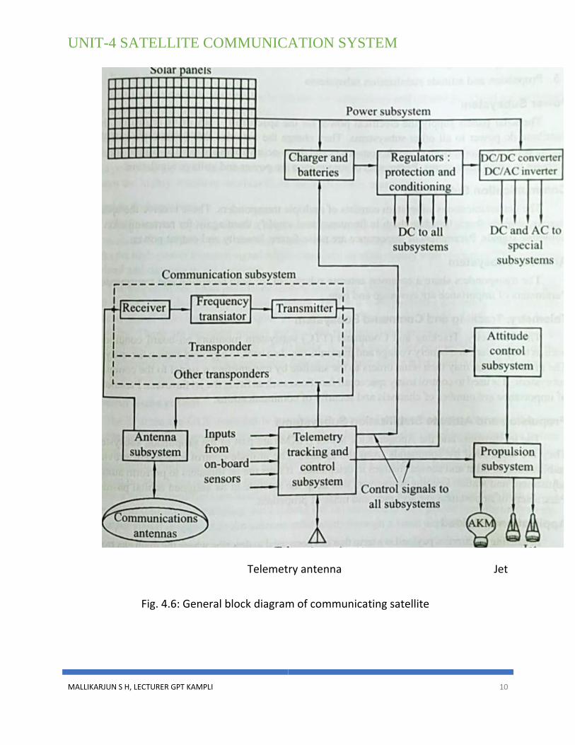
GENERAL BLOCK DIAGRAM OF COMMUNICATION
SATELLITE
Fig. 4.6 shows the block diagram of a communications satellite. The heart of a
communications satellite is the communications subsystem. This is a set of transponders that
receive the uplink signals and retransmit them to earth. The transponders are supported by a
number of housekeeping subsystems. The main subsystems that constitute a satellite are as
follows:
❖ Power subsystem
❖ Communication subsystem
❖ Antenna subsystem
❖ Telemetry, tracking and command subsystems
❖ Propulsion and attitude stabilization subsystems
UNIT-4 SATELLITE COMMUNICATION SYSTEM
MALLIKARJUN S H, LECTURER GPT KAMPLI 10
Telemetry antenna Jet
Fig. 4.6: General block diagram of communicating satellite

UNIT-4 SATELLITE COMMUNICATION SYSTEM
MALLIKARJUN S H, LECTURER GPT KAMPLI 11
Power Subsystem
The solar panels supply the electrical power for the spacecraft. They drive regulators
that distribute dc power to all other subsystems. They charge the batteries that operate the
satellite during eclipse periods. Both dc-to-dc converters and dc-to-ac inverters are used to
supply special voltages to some subsystems. Parameters of importance are power and voltage
regulation.
Communication Subsystem
The communications subsystem consists of multiple transponders. These receive the
uplink signals, amplify them, translate them in frequency and amplify them again for
retransmission downlink signals. Parameters of importance are noise figure, linearity and
output power.
Antenna Subsystem
The transponders share a common antenna subsystem for both reception and
transmission Parameters of importance are coverage and gain.
Telemetry, Tracking and Command Subsystem
The Telemetry, Tracking and Command (TTC) subsystem monitors on-board
conditions such as temperature and battery voltage and transmits this data back to a ground
station for analysis. The ground station may then issue orders to the satellite by transmitting a
signal to the command subsystem. It is used to control many spacecraft functions such as firing
the jet thrusters. Parameters of importance are number of channels and security of
communications.
Propulsion and Attitude Stabilization Subsystems
The jet thrusters and the Apogee Kick Motor (AKM) are part of the propulsion
subsystem They are controlled by commands from the ground. The attitude-control subsystem
provides stabilization in orbit and senses changes in orientation. It fires the jet thrusters to
perform attitude adjustment and station keeping maneuvers that keep the satellite in its
assigned orbital position, Parameters of importance are accuracy and mass of propellant.
Applications Payload
In satellite electronics payload is a term that has been used to describe where the main
electronic circuits are. The main payload on a communications satellite is the communications
subsystem that performs the function of a repeater or relay station.

UNIT-4 SATELLITE COMMUNICATION SYSTEM
MALLIKARJUN S H, LECTURER GPT KAMPLI 12
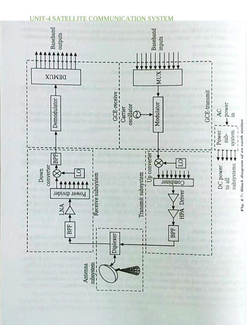
SATELLITE EARTHSTATION
Fig. 4.7 gives the block diagram of an earth station which transmits signal to a satellite
and receives signal from the satellite. An earth station consists of the following five main
subsystems:
➢ Antenna subsystem
➢ Receive subsystem
➢ Transmit subsystem
➢ Ground communications equipment (GCE) subsystem
➢ Power subsystem
Many earth stations have multiple circuits for redundancy and reliability. These are
switched on automatically if the main unit fails.
Antenna Subsystem
The antenna subsystem consists of the parabolic reflector, the horn antenna, related
mounts and a polarized diplexer that permits both the transmitter and receiver to use the same
antenna. It isolates the highly sensitive receiver from the high-power transmitter.
Receive Subsystem
The polarized diplexer feeds a band pass filter in the receiver section that ensures that
only the received frequencies pass through to the sensitive receiving circuits. This band pass
filter blocks the high-power transmit signal which can occur simultaneously with reception.
This prevents overload and damage to the receiver.
The output of the band pass filter feeds a low-noise amplifier (LNA) with an extremely
low noise figure. The LNA drives a power divider. This is a waveguide like assembly that
splits the received signal into smaller but equal power signals. The power divider feeds several
down converters. These are standard mixers fed by LOS that translate the received signals
down to an intermediate frequency (IF), usually of 70 MHz A band pass filter ensures the
selection of the proper sidebands out of the down converter. Any original modulation is
retained during the frequency translation process.
Transmit Subsystem

UNIT-4 SATELLITE COMMUNICATION SYSTEM
MALLIKARJUN S H, LECTURER GPT KAMPLI 13
The IF from the GCE-transmit is translated to the final output frequency by way of an
upconverter circuit. The up-converter is a mixer with its local oscillator tuned to generate the
uplink frequency. All the up-converted signals are then applied to a power combiner. This
waveguide like device equally combines all the RF signals into the final signal to be
transmitted. This feeds a driver circuit which has sufficient power to operate the final amplifier
high power amplifier (HPA). Transistor power amplifiers are used in low power earth stations,
klystrons are used in high power narrow band stations and traveling wave tubes (TWTs) are
used in high power broadband systems. The output signal is applied to the antenna subsystem
through a band pass filter.
Ground Communications Equipment (GCE) Subsystem
GCE subsystem consists of both receiving and transmitting circuits. receiving portion,
referred to as GCE-receive, consists of down converters, filters. demodulators and
demultiplexing equipment. The transmit portion, referred to as GCE-transmit, consists of
multiplexers, modulators. up converters and the related filters. Connections to the telephone
system. terrestrial microwave relay links, computer interfaces and so on are made through the
GCE subsystem
GCE-Receive
GCE-receive, demodulator recovers the baseband signal (voice, video or digital data).
Demultiplexer is used for sorting and sending the baseband signals to their respective
destinations. The IF signal containing the data from the receive subsystem is sent to the
receive GCE where it is demodulated and fed to a demultiplexer. The original signals are
finally obtained at the output of the demultiplexer. The demultiplexer outputs are the baseband
or original communications signals. In actual systems, several levels of demodulation and
demultiplexing may have to take place to obtain the original signals.
GCE-Transmit
In the GCE-transmit, the baseband signals such as telephone signals, video or computer
data are applied to a multiplexer which permits multiple signals to be carried on a single
channel. The multiplexed composite signals are applied to a modulator along with the carrier
oscillator operating at the IF of 70 MHz This IF is transmitted to the transmit subsystem.
Common forms of modulation are FM (for voice and video) and QPSK (for data). Several
levels of multiplexing and modulation may be used depending upon the application.
UNIT-4 SATELLITE COMMUNICATION SYSTEM
MALLIKARJUN S H, LECTURER GPT KAMPLI 14

UNIT-4 SATELLITE COMMUNICATION SYSTEM
MALLIKARJUN S H, LECTURER GPT KAMPLI 15
Power Subsystem
The power subsystem supplies power to the equipment. The primary sources of power are
the standard ac power lines. The power subsystem also consists of emergency power sources
such as diesel generators, batteries and inverters to ensure continuous operation during power
failures.
REVIEW QUESTIONS
5 Marks Questions
1. Define Satellite frequency allocation and bandwidth.
2. Define Transponders and List the types of satellite transponders.
3. List the different types of satellite subsystems.
4. Explain Single conversion transponder with neat sketch.
5. Explain double conversion transponder with neat sketch.
6. Explain Regenerative transponder with neat sketch.
7. Explain Power subsystem of a satellite.
8. Explain TT&C subsystem of a satellite.
9. Explain applications payload of a satellite.
10. Illustrate the importance of a transponder in a satellite system.
11. Explain methods of increasing channel capacity of a satellite.
12. Explain Frequency and spatial isolation techniques for increasing the satellite
channel capacity.
13. Describe the general block diagram of a communication satellite.
10 Marks Questions
1. Explain the working of TTC satellite subsystem with neat block diagram.
2. Explain working of a satellite earth station with block diagram.
3. Describe transponder. Explain working of regenerative transponder with neat
sketch.