Embed Size (px)
Citation preview

KSIT[CSE]
1
UNIT 2
MACHINE INSTRUCTIONS & PROGRAMS (CONT.)
ADDRESSING MODES
• The different ways in which the location of an operand is specified in an instruction are referred to as addressing modes (Table 2.1).
IMPLEMENTATION OF VARIABLE AND CONSTANTS
• Variables & constants are the simplest data-types and are found in almost every computer program.
• In assembly language, a variable is represented by allocating a register (or memory-location) to hold its value. Thus, the value can be
changed as needed using appropriate instructions.
Register Mode
• The operand is the contents of a register.
• The name (or address) of the register is given in the instruction.
• Registers are used as temporary storage locations where the data in a register are accessed.
• For example, the instruction,
Move R1, R2 ;Copy content of register R1 into register R2
Absolute (Direct) Mode
• The operand is in a memory-location.
• The address of memory-location is given explicitly in the instruction.
• For example, the instruction,
Move LOC, R2 ;Copy content of memory-location LOC into register R2
Immediate Mode
• The operand is given explicitly in the instruction.
• For example, the instruction,
Move #200, R0 ;Place the value 200 in register R0
• Clearly, the immediate mode is only used to specify the value of a source-operand.
KSIT[CSE]
2
INDIRECTION AND POINTERS
• In this case, the instruction does not give the operand or its address explicitly; instead, it provides information from which the memory-
address of the operand can be determined. We refer to this address as the effective address(EA) of the operand.
Indirect Mode
• The EA of the operand is the contents of a register(or memory-location) whose address appears in the instruction.
• The register (or memory-location) that contains the address of an operand is called a pointer. {The indirection is denoted by ( ) sign around the
register or memory-location}.
E.g: Add (R1),R0 ;The operand is in memory. Register R1 gives the effective-address(B) of the operand. The data
is read from location B and added to contents of register R0
* To execute the Add instruction in fig (a), the processor uses the value which is in register R1, as the EA of the operand.
* It requests a read operation from the memory to read the contents of location B. The value read is the desired operand, which the processor adds to the contents
of register R0.
* Indirect addressing through a memory location is also possible as shown in fig (b). In this case, the processor first reads the contents of memory location A,
then requests a second read operation using the value B as an address to obtain the operand
• In above program, Register R2 is used as a pointer to the numbers in the list, and the operands are accessed indirectly through R2.
• The initialization-section of the program loads the counter-value n from memory-location N into R1 and uses the immediate addressing-mode
to place the address value NUM1, which is the address of the first number in the list, into R2. Then it clears R0 to 0.
• The first two instructions in the loop implement the unspecified instruction block starting at LOOP.
• The first time through the loop, the instruction Add (R2), R0 fetches the operand at location NUM1 and adds it to R0.
• The second Add instruction adds 4 to the contents of the pointer R2, so that it will contain the address value NUM2 when the above
instruction is executed in the second pass through the loop.

KSIT[CSE]
3
INDEXING AND ARRAYS
• A different kind of flexibility for accessing operands is useful in dealing with lists and arrays.
Index mode
• The operation is indicated as X(Ri)
where X=the constant value contained in the instruction Ri=the name of the
index register
• The effective-address of the operand is given by EA=X+[Ri]
• The contents of the index-register are not changed in the process of generating the effective-address.
• In an assembly language program, the constant X may be given either
→ as an explicit number or
→ as a symbolic-name representing a numerical value.
* Fig(a) illustrates two ways of using the Index mode. In fig(a), the index register, R1, contains the address of a memory location, and the value X defines
an offset(also called a displacement) from this address to the location where the operand is found.
* An alternative use is illustrated in fig(b). Here, the constant X corresponds to a memory address, and the contents of the index register define the offset to the
operand. In either case, the effective address is the sum of two values; one is given explicitly in the instruction, and the other is stored in a register.
Base with Index Mode
• Another version of the Index mode uses 2 registers which can be denoted as (Ri, Rj)
• Here, a second register may be used to contain the offset X.
• The second register is usually called the base register.
• The effective-address of the operand is given by EA=[Ri]+[Rj]
• This form of indexed addressing provides more flexibility in accessing operands, because both components of
the effective address can be changed.
Base with Index & Offset Mode
• Another version of the Index mode uses 2 registers plus a constant, which can be denoted as X(Ri, Rj)
• The effective-address of the operand is given by EA=X+[Ri]+[Rj]
• This added flexibility is useful in accessing multiple components inside each item in a record, where the beginning of an item is
specified by the (Ri, Rj) part of the addressing-mode. In other words, this mode implements a 3-dimensional array.

KSIT[CSE]
4
RELATIVE MODE
• This is similar to index-mode with an exception: The effective address is determined using the PC in place of the general purpose register Ri.
• The operation is indicated as X(PC).
• X(PC) denotes an effective-address of the operand which is X locations above or below the current contents of PC.
• Since the addressed-location is identified "relative" to the PC, the name Relative mode is associated with this type of addressing.
• This mode is used commonly in conditional branch instructions.
• An instruction such as
Branch > 0 LOOP ;Causes program execution to go to the branch target location identified by
name LOOP if branch condition is satisfied.
ADDITIONAL ADDRESSING MODES
• The following 2 modes are useful for accessing data items in successive locations in the memory.
Auto-increment Mode
• The effective-address of operand is the contents of a register specified in the instruction (Fig: 2.16).
• After accessing the operand, the contents of this register are automatically incremented to point to the next item in a list.
• Implicitly, the increment amount is 1.
• This mode is denoted as
(Ri)+ ;where Ri=pointer register
Auto-decrement Mode
• The contents of a register specified in the instruction are first automatically decremented and are then used as the effective address of the
operand.
• This mode is denoted as
-(Ri) ;where Ri=pointer register
• These 2 modes can be used together to implement an important data structure called a stack.

KSIT[CSE]
5
ASSEMBLY LANGUAGE
• A complete set of symbolic names and rules for their use constitute an assembly language.
• The set of rules for using the mnemonics in the specification of complete instructions and programs is called the
syntax of the language.
• Programs written in an assembly language can be automatically translated into a sequence of machine instructions by a program
called an assembler.
• The user program in its original alphanumeric text formal is called a source program, and the assembled machine language program
is called an object program.
• Move instruction is written is
MOVE R0,SUM ;The mnemonic MOVE represents the binary pattern, or OP code, for the operation performed by the
instruction.
• The instruction
ADD #5,R3 ;Adds the number 5 to the contents of register R3 and puts the result back into register R3.
ASSEMBLER DIRECTIVES
• EQU informs the assembler about the value of an identifier (Figure: 2.18).
Ex: SUM EQU 200 ; This statement informs the assembler that the name SUM should be replaced by the value
200 wherever it appears in the program.
• ORIGIN tells the assembler about the starting-address of memory-area to place the data block.
• DATAWORD directive tells the assembler to load a value (say 100) into the location (say 204). Ex: N DATAWORD
100
• RESERVE directive declares that a memory-block of 400 bytes is to be reserved for data and that the name NUM1 is to be associated
with address 208.
Ex: NUM1 RESERVE 400
• END directive tells the assembler that this is the end of the source-program text.
• RETURN directive identifies the point at which execution of the program should be terminated.
• Any statement that makes instructions or data being placed in a memory-location may be given a label.
• The label(say N or NUM1) is assigned a value equal to the address of that location.
GENERAL FORMAT OF A STATEMENT
• Most assembly languages require statements in a source program to be written in the form:
Label Operation Operands Comment
→ Label is an optional name associated with the memory-address where the machine language instruction produced
from the statement will be loaded.
→ The Operation field contains the OP-code mnemonic of the desired instruction or assembler → The Operand field contains
addressing information for accessing one or more operands,
depending on the type of instruction.

KSIT[CSE]
6
→ The Comment field is used for documentation purposes to make the program easier to understand.

KSIT[CSE]
7
ASSEMBLY AND EXECUTION OF PRGRAMS
• Programs written in an assembly language are automatically translated into a sequence of machine instructions by the assembler.
• Assembler program
→ replaces all symbols denoting operations & addressing-modes with binary-codes used in machine instructions.
→ replaces all names and labels with their actual values.
→ assigns addresses to instructions & data blocks, starting at the address given in the ORIGIN directive.
→ inserts constants that may be given in DATAWORD directives.
→ reserves memory-space as requested by RESERVE directives.
• As the assembler scans through a source-program, it keeps track of all names of numerical-values that correspond to them in a
symbol-table. Thus, when a name appears a second time, it is replaced with its value from the table. Hence, such an assembler is called a two-
pass assembler.
• The assembler stores the object-program on a magnetic-disk. The object-program must be loaded into the memory of the computer
before it is executed. For this, a loader program is used.
• Debugger program is used to help the user find the programming errors.
• Debugger program enables the user
→ to stop execution of the object-program at some points of interest and
→ to examine the contents of various processor registers and memory-location
KSIT[CSE]
8
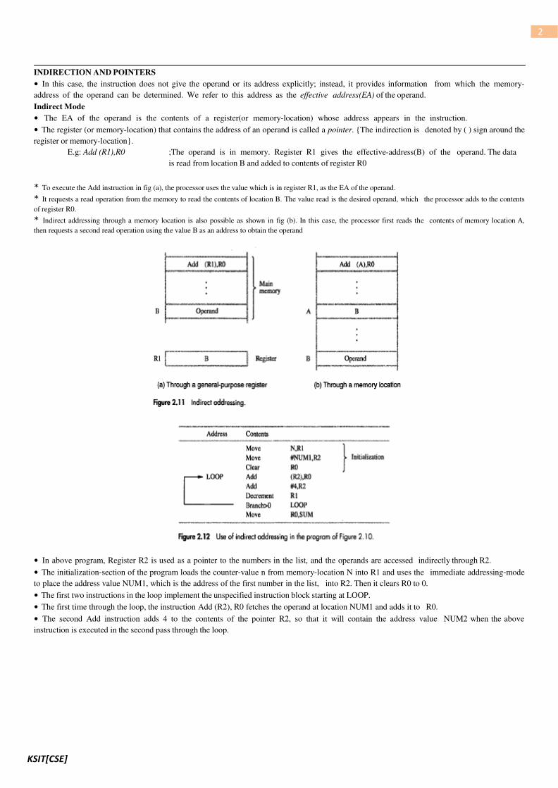
BASIC INPUT/OUTPUT OPERATIONS
• Consider the problem of moving a character-code from the keyboard to the processor. For this transfer, buffer-
register(DATAIN) & a status control flags(SIN) are used.
• Striking a key stores the corresponding character-code in an 8-bit buffer-register(DATAIN) associated with the keyboard (Figure: 2.19).
• To inform the processor that a valid character is in DATAIN, a SIN is set to 1.
• A program monitors SIN, and when SIN is set to 1, the processor reads the contents of DATAIN.
• When the character is transferred to the processor, SIN is automatically cleared to 0.
• If a second character is entered at the keyboard, SIN is again set to 1 and the process repeats.
• An analogous process takes place when characters are transferred from the processor to the display. A buffer- register, DATAOUT, and a
status control flag, SOUT are used for this transfer.
• When SOUT=1, the display is ready to receive a character.
• The transfer of a character to DATAOUT clears SOUT to 0.
• The buffer registers DATAIN and DATAOUT and the status flags SIN and SOUT are part of circuitry commonly known as a device
interface.
• Following is a program to read a line of characters and display it
MEMORY-MAPPED I/O
• Some address values are used to refer to peripheral device buffer-registers such as DATAIN and DATAOUT.
• No special instructions are needed to access the contents of the registers; data can be transferred between these registers and the processor using
instructions such as Move, Load or Store.
• For example, contents of the keyboard character buffer DATAIN can be transferred to register R1 in the processor by the
instruction
MoveByte DATAIN,R1
• The MoveByte operation code signifies that the operand size is a byte.
• The Testbit instruction tests the state of one bit in the destination, where the bit position to be tested is indicated by the first
operand.

KSIT[CSE]
9
STACKS
• A stack is a list of data elements with the accessing restriction that elements can be added or removed at one end of the list only. This end
is called the top of the stack, and the other end is called the bottom (Figure: 2.21).
• The terms push and pop are used to describe placing a new item on the stack and removing the top item from the stack, respectively.
• A processor-register is used to keep track of the address of the element of the stack that is at the top at any given time. This register is
called the SP (Stack Pointer).
• If we assume a byte-addressable memory with a 32-bit word length,
→ The push operation can be implemented as
Subtract #4,SR Move
NEWITEM,(SP)
→ The pop operation can be implemented as
Move (SP),ITEM Add
#4,SP
• Routine for a safe pop and push operation as follows

KSIT[CSE]
10
QUEUE
• Data are stored in and retrieved from a queue on a FIFO basis.
• Difference between stack and queue?
1) One end of the stack is fixed while the other end rises and falls as data are pushed and popped.
2) A single pointer is needed to point to the top of the stack at any given time.
On the other hand, both does of a queue move to higher addresses as data are added at the back and removed
from the front. So, two pointers are needed to keep track of the two does of the queue.
3) Without further control, a queue would continuously move through the memory of a computer in the direction of higher
addresses. One way to limit the queue to a fixed region in memory is to use a circular buffer.
SUBROUTINES
• A subtask consisting of a set of instructions which is executed many times is called a subroutine.
• The program branches to a subroutine with a Call instruction (Figure: 2.24).
• Once the subroutine is executed, the calling-program must resume execution starting from the instruction immediately following the
Call instructions i.e. control is to be transferred back to the calling-program. This is done by executing a Return instruction at the end of the
subroutine.
• The way in which a computer makes it possible to call and return from subroutines is referred to as its
subroutine linkage method.
• The simplest subroutine linkage method is to save the return-address in a specific location, which may be a register dedicated to this
function. Such a register is called the link register.
• When the subroutine completes its task, the Return instruction returns to the calling-program by branching indirectly through the link-
register.
• The Call instruction is a special branch instruction that performs the following operations:
→ Store the contents of PC into link-register.
→ Branch to the target-address specified by the instruction.
• The Return instruction is a special branch instruction that performs the operation:
→ Branch to the address contained in the link-register.

KSIT[CSE]
11
SUBROUTINE NESTING AND THE PROCESSOR STACK
• Subroutine nesting means one subroutine calls another subroutine.
• In this case, the return-address of the second call is also stored in the link-register, destroying its previous contents.
• Hence, it is essential to save the contents of the link-register in some other location before calling another subroutine. Otherwise, the
return-address of the first subroutine will be lost.
• Subroutine nesting can be carried out to any depth. Eventually, the last subroutine called completes its computations and returns to
the subroutine that called it.
• The return-address needed for this first return is the last one generated in the nested call sequence. That is, return-addresses are generated
and used in a LIFO order.
• This suggests that the return-addresses associated with subroutine calls should be pushed onto a stack. A particular register is
designated as the SP(Stack Pointer) to be used in this operation.
• SP is used to point to the processor-stack.
• Call instruction pushes the contents of the PC onto the processor-stack.
Return instruction pops the return-address from the processor-stack into the PC.
PARAMETER PASSING
• The exchange of information between a calling-program and a subroutine is referred to as parameter passing
(Figure: 2.25).
• The parameters may be placed in registers or in memory-location, where they can be accessed by the subroutine.
• Alternatively, parameters may be placed on the processor-stack used for saving the return-address • Following is a program for adding a list
of numbers using subroutine with the parameters passed through registers.
KSIT[CSE]
12
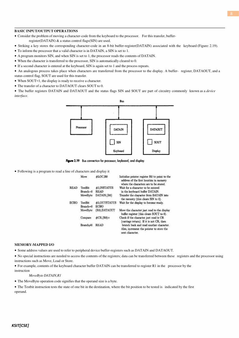
STACK FRAME
• Stack frame refers to locations that constitute a private work-space for the subroutine(Figure:2.26).
• The work-space is
→ created at the time the subroutine is entered &
→ freed up when the subroutine returns control to the calling-program.
• Following is a program for adding a list of numbers using subroutine with the parameters passed to stack
• Fig: 2.27 show an example of a commonly used layout for information in a stack-frame.
• Frame pointer(FP) is used to access the parameters passed
→ to the subroutine &
→ to the local memory-variables
• The contents of FP remains fixed throughout the execution of the subroutine, unlike stack-pointer SP, which must always point to the
current top element in the stack.

KSIT[CSE]
13
Operation on Stack Frame
• Initially SP is pointing to the address of oldTOS.
• The calling-program saves 4 parameters on the stack (Figure 2.27).
• The Call instruction is now executed, pushing the return-address onto the stack.
• Now, SP points to this return-address, and the first instruction of the subroutine is executed.
• Now, FP is to be initialized and its old contents have to be stored. Hence, the first 2 instructions in the subroutine are:
Move FP,-(SP)
Move SP,FP
• The FP is initialized to the value of SP i.e. both FP and SP point to the saved FP address.
• The 3 local variables may now be pushed onto the stack. Space for local variables is allocated by executing the instruction
Subtract #12,SP
• Finally, the contents of processor-registers R0 and R1 are saved in the stack. At this point, the stack-frame has been set up as shown in the fig
2.27.
• The subroutine now executes its task. When the task is completed, the subroutine pops the saved values of R1 and R0 back into those
registers, removes the local variables from the stack frame by executing the instruction.
Add #12, SP
• And subroutine pops saved old value of FP back into FP. At this point, SP points to return-address, so the Return instruction can be executed,
transferring control back to the calling-program.
KSIT[CSE]
14
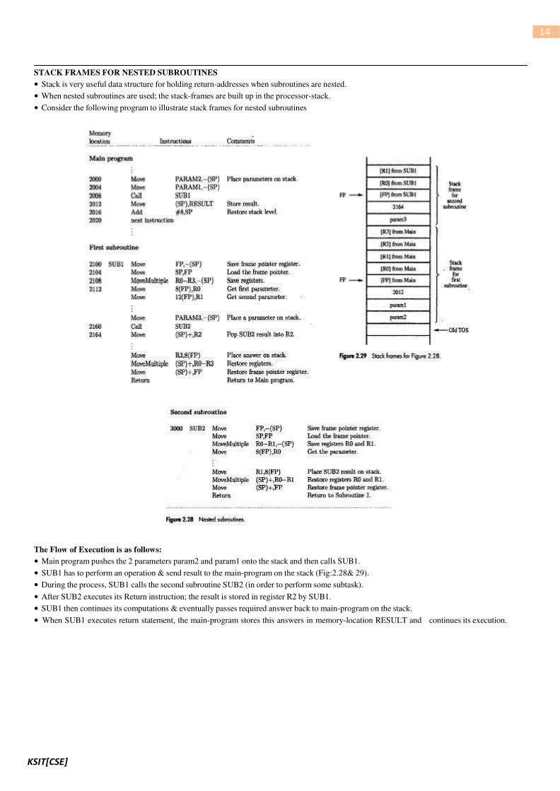
STACK FRAMES FOR NESTED SUBROUTINES
• Stack is very useful data structure for holding return-addresses when subroutines are nested.
• When nested subroutines are used; the stack-frames are built up in the processor-stack.
• Consider the following program to illustrate stack frames for nested subroutines
The Flow of Execution is as follows:
• Main program pushes the 2 parameters param2 and param1 onto the stack and then calls SUB1.
• SUB1 has to perform an operation & send result to the main-program on the stack (Fig:2.28& 29).
• During the process, SUB1 calls the second subroutine SUB2 (in order to perform some subtask).
• After SUB2 executes its Return instruction; the result is stored in register R2 by SUB1.
• SUB1 then continues its computations & eventually passes required answer back to main-program on the stack.
• When SUB1 executes return statement, the main-program stores this answers in memory-location RESULT and continues its execution.

KSIT[CSE]
15
LOGIC INSTRUCTIONS
• Logic operations such as AND, OR, and NOT applied to individual bits.
• These are the basic building blocks of digital-circuits.
• This is also useful to be able to perform logic operations is software, which is done using instructions that apply these operations to all bits of
a word or byte independently and in parallel.
• For example, the instruction
Not dst
SHIFT AND ROTATE INSTRUCTIONS
• There are many applications that require the bits of an operand to be shifted right or left some specified number of bit positions.
• The details of how the shifts are performed depend on whether the operand is a signed number or some more general binary-coded
information.
• For general operands, we use a logical shift.
For a number, we use an arithmetic shift, which preserves the sign of the number.
LOGICAL SHIFTS
• Two logical shift instructions are needed, one for shifting left(LShiftL) and another for shifting right(LShiftR).
• These instructions shift an operand over a number of bit positions specified in a count operand contained in the instruction.

KSIT[CSE]
16
ROTATE OPERATIONS
• In shift operations, the bits shifted out of the operand are lost, except for the last bit shifted out which is retained in the Carry-flag C.
• To preserve all bits, a set of rotate instructions can be used.
• They move the bits that are shifted out of one end of the operand back into the other end.
• Two versions of both the left and right rotate instructions are usually provided. In one version, the
bits of the operand is simply rotated.
In the other version, the rotation includes the C flag.
KSIT[CSE]
17
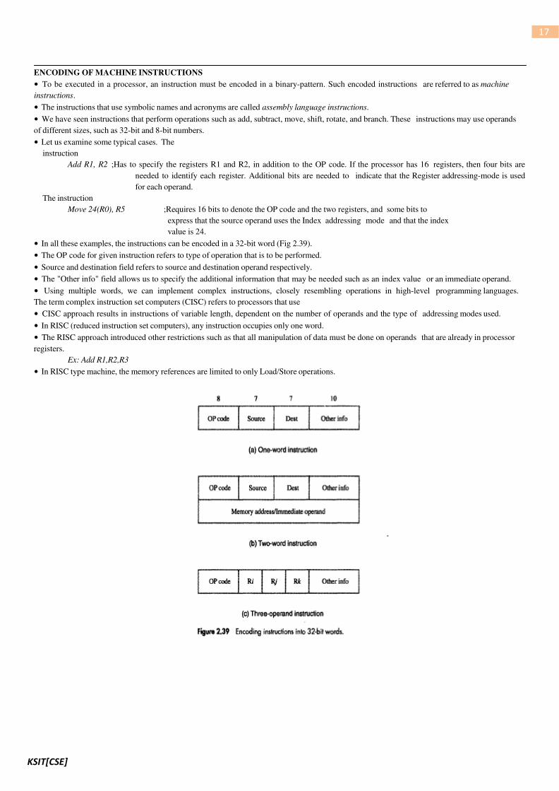
ENCODING OF MACHINE INSTRUCTIONS
• To be executed in a processor, an instruction must be encoded in a binary-pattern. Such encoded instructions are referred to as machine
instructions.
• The instructions that use symbolic names and acronyms are called assembly language instructions.
• We have seen instructions that perform operations such as add, subtract, move, shift, rotate, and branch. These instructions may use operands
of different sizes, such as 32-bit and 8-bit numbers.
• Let us examine some typical cases. The
instruction
Add R1, R2 ;Has to specify the registers R1 and R2, in addition to the OP code. If the processor has 16 registers, then four bits are
needed to identify each register. Additional bits are needed to indicate that the Register addressing-mode is used
for each operand.
The instruction
Move 24(R0), R5 ;Requires 16 bits to denote the OP code and the two registers, and some bits to
express that the source operand uses the Index addressing mode and that the index
value is 24.
• In all these examples, the instructions can be encoded in a 32-bit word (Fig 2.39).
• The OP code for given instruction refers to type of operation that is to be performed.
• Source and destination field refers to source and destination operand respectively.
• The "Other info" field allows us to specify the additional information that may be needed such as an index value or an immediate operand.
• Using multiple words, we can implement complex instructions, closely resembling operations in high-level programming languages.
The term complex instruction set computers (CISC) refers to processors that use
• CISC approach results in instructions of variable length, dependent on the number of operands and the type of addressing modes used.
• In RISC (reduced instruction set computers), any instruction occupies only one word.
• The RISC approach introduced other restrictions such as that all manipulation of data must be done on operands that are already in processor
registers.
Ex: Add R1,R2,R3
• In RISC type machine, the memory references are limited to only Load/Store operations.

KSIT[CSE]
18
UNIT 3: INPUT/OUTPUT ORGANIZATION
ACCESSING I/O DEVICES
• There are 2 ways to deal with I/O devices (Figure 4.1).
1) Memory mapped I/O
• Memory and I/O devices share a common address-space.
• Any data-transfer instruction(like Move, Load) can be used to exchange information.
• For example, Move DATAIN, R0 ;this instruction reads data from DATAIN(input-buffer associated with keyboard) & stores
them into processor-register R0.
2) In I/O mapped I/O, memory and I/0 address-spaces are different.
• A special instructions named IN and OUT are used for data transfer.
• Advantage of separate I/O space: I/O devices deal with fewer address-lines.
I/O Interface for an Input Device
• Address decoder: decodes address sent on bus, so as to enable input-device (Figure 4.2).
• Data register: holds data being transferred to or from the processor.
• Status register: contains information relevant to operation of I/O device.
• Address decoder, data- and status-registers, and control-circuitry required to coordinate I/O transfers constitute device's interface-circuit.

KSIT[CSE]
19
MECHANISMS USED FOR INTERFACING I/O DEVICES
1) Program Controlled I/O
• Processor repeatedly checks a status-flag to achieve required synchronization between processor & input/output device. (We
say that the processor polls the device).
• Main drawback: The processor wastes its time in checking the status of the device before actual data transfer takes place.
2) Interrupt I/O
• Synchronization is achieved by having I/O device send a special signal over bus whenever it is ready for a data transfer operation.
3) Direct Memory Access (DMA)
•This involves having the device-interface transfer data directly to or from the memory without continuous involvement by the
processor.
INTERRUPTS
• I/O device initiates the action instead of the processor. This is done by sending a special hardware signal to the processor called as
interrupt(INTR), on the interrupt-request line.
• The processor can be performing its own task without the need to continuously check the I/O device.
• When device gets ready, it will "alert" the processor by sending an interrupt-signal (Figure 4.5).
• The routine executed in response to an interrupt-request is called ISR(Interrupt Service Routine).
• Once the interrupt-request signal comes from the device, the processor has to inform the device that its request has been recognized and will
be serviced soon. This is indicated by a special control signal on the bus called interrupt-acknowledge(INTA).
Difference between subroutine & ISR
• A subroutine performs a function required by the program from which it is called.
However, the ISR may not have anything in common with the program being executed at the time the interrupt-
request is received. Before starting execution of ISR, any information that may be altered during the execution of that
routine must be saved. This information must be restored before the interrupted-program resumed.
• Another difference is that an interrupt is a mechanism for coordinating I/O transfers whereas a subroutine is just
a linkage of 2 or more function related to each other.
Note:
• The speed of operation of the processor and I/O devices differ greatly. Also, since I/O devices are manually operated in many cases
(like pressing a key on keyboard), there may not be synchronization between the CPU operations and I/O operations with reference to CPU
clock. To cater to the different needs of I/O operations, 3 mechanisms have been developed for interfacing I/O devices. 1) Program controlled
I/O 2) Interrupt I/O 3) Direct memory access (DMA).
• Saving registers increases the delay between the time an interrupt request is received and the start of execution of the ISR. This delay is called
interrupt latency.
• Since interrupts can arrive at any time, they may alter the sequence of events. Hence, facility must be provided to enable and disable
interrupts as desired.
• Consider the case of a single interrupt request from one device. The device keeps the interrupt request signal activated until it is informed
that the processor has accepted its request. This activated signal, if not deactivated may lead to successive interruptions, causing the system to
enter into an infinite loop.

KSIT[CSE]
20
INTERRUPT HARDWARE
• An I/O device requests an interrupt by activating a bus-line called interrupt-request(IR).
• A single IR line can be used to serve „n‟ devices (Figure 4.6).
• All devices are connected to IR line via switches to ground.
• To request an interrupt, a device closes its associated switch. Thus, if all IR signals are inactive(i.e. if all switches are open), the voltage on the
IR line will be equal to Vdd.
• When a device requests an interrupt by closing its switch, the voltage on the line drops to 0, causing the INTR
received by the processor to goto 1.
• The value of INTR is the logical OR of the requests from individual devices INTR=INTR1+
INTR2+ . . . . . +INTRn
• A special gates known as open-collector or open-drain are used to drive the INTR line.
• Resistor R is called a pull-up resistor because
it pulls the line voltage up to the high-voltage state when the switches are open.
ENABLING & DISABLING INTERRUPTS
• To prevent the system from entering into an infinite-loop because of interrupt, there are 3 possibilities:
1) The first possibility is to have the processor-hardware ignore the interrupt-request line until the execution of the first
instruction of the ISR has been completed.
2) The second option is to have the processor automatically disable interrupts before starting the execution of the ISR.
3) In the third option, the processor has a special interrupt-request line for which the interrupt-handling circuit responds only to the
leading edge of the signal. Such a line is said to be edge-triggered.
• Sequence of events involved in handling an interrupt-request from a single device is as follows:
1) The device raises an interrupt-request.
2) The program currently being executed is interrupted.
3) All interrupts are disabled(by changing the control bits in the PS).
4) The device is informed that its request has been recognized, and
in response, the device deactivates the interrupt-request signal.
5) The action requested by the interrupt is performed by the ISR.
6) Interrupts are enabled again and execution of the interrupted program is resumed.

KSIT[CSE]
21
HANDLING MULTIPLE DEVICES
Polling
• Information needed to determine whether a device is requesting an interrupt is available in its status-register.
• When a device raises an interrupt-request, it sets IRQ bit to 1 in its status-register (Figure 4.3).
• KIRQ and DIRQ are the interrupt-request bits for keyboard & display.
• Simplest way to identify interrupting device is to have ISR poll all I/O devices connected to bus.
• The first device encountered with its IRQ bit set is the device that should be serviced. After servicing this device, next requests may be
serviced.
• Main advantage: Simple & easy to implement.
Main disadvantage: More time spent polling IRQ bits of all devices (that may not be requesting any service).
Vectored Interrupts
• A device requesting an interrupt identifies itself by sending a special-code to processor over bus. (This enables processor to identify
individual devices even if they share a single interrupt-request line).
• The code represents starting-address of ISR for that device.
• ISR for a given device must always start at same location.
• The address stored at the location pointed to by interrupting-device is called the interrupt-vector.
• Processor
→ loads interrupt-vector into PC &
→ executes appropriate ISR
• Interrupting-device must wait to put data on bus only when processor is ready to receive it.
• When processor is ready to receive interrupt-vector code, it activates INTA line.
• I/O device responds by sending its interrupt-vector code & turning off the INTR signal.

KSIT[CSE]
22
CONTROLLING DEVICE REQUESTS
• There are 2 independent mechanisms for controlling interrupt requests.
• At device-end, an interrupt-enable bit in a control register determines whether device is allowed to generate an interrupt request.
• At processor-end, either an interrupt-enable bit in the PS register or a priority structure determines whether a given interrupt-request will be
accepted.

KSIT[CSE]
23
INTERRUPT NESTING
• A multiple-priority scheme is implemented by using separate INTR & INTA lines for each device
• Each of the INTR lines is assigned a different priority-level (Figure 4.7).
• Priority-level of processor is the priority of program that is currently being executed.
• During execution of an ISR, interrupt-requests will be accepted from some devices but not from others
depending upon device‟s priority.
• Processor accepts interrupts only from devices that have priority higher than its own.
• At the time of execution of an ISR for some device is started, priority of processor is raised to that of the device
• Processor's priority is encoded in a few bits of processor-status(PS) word. This can be changed by program instructions that write into
PS. These are called privileged instructions.
• Privileged-instructions can be executed only while processor is running in supervisor-mode.
• Processor is in supervisor-mode only when executing operating-system routines. (An attempt to execute a privileged-instruction while
in the user-mode leads to a special type of interrupt called a privileged exception).
SIMULTANEOUS REQUESTS
• INTR line is common to all devices (Figure 4.8).
• INTA line is connected in a daisy-chain fashion such that INTA signal propagates serially through devices.
• When several devices raise an interrupt-request and INTR line is activated, processor responds by setting INTA line to 1. This signal is
received by device 1.
• Device 1 passes signal on to device 2 only if it does not require any service.
• If device 1 has a pending-request for interrupt, it blocks INTA signal and proceeds to put its identifying code on data lines.
• Device that is electrically closest to processor has highest priority.
• Main advantage: This allows the processor to accept interrupt-requests from some devices but not from others depending
upon their priorities.

KSIT[CSE]
24
EXCEPTIONS
• An interrupt is an event that causes
→ execution of one program to be suspended &
→ execution of another program to begin.
• Exception refers to any event that causes an interruption. I/O interrupts
are one example of an exception.
Recovery from Errors
• Computers use a variety of techniques to ensure that all hardware-components are operating properly. For e.g. many computers include an
error-checking code in main-memory which allows detection of errors in stored-data.
• If an error occurs, control-hardware detects it & informs processor by raising an interrupt.
• When exception processing is initiated (as a result of errors), processor
→ suspends program being executed &
→ starts an ESR(Exception Service Routine). This routine takes appropriate action to recover from the error to inform user about
it.
Debugging
• Debugger
→ helps programmer find errors in a program and
→ uses exceptions to provide 2 important facilities: 1) Trace & 2) Breakpoints
• When a processor is operating in trace-mode, an exception occurs after execution of every instruction (using debugging-program as ESR).
• Debugging-program enables user to examine contents of registers (AX, BX), memory-locations and so on.
• On return from debugging-program,
next instruction in program being debugged is executed, then debugging-
program is activated again.
• Breakpoints provide a similar facility except that program being debugged is interrupted only at specific points selected by user. An
instruction called Trap(or Software interrupt) is usually provided for this purpose.
Privilege Exception
• To protect OS of computer from being corrupted by user-programs, certain instructions can be executed only while processor is in
supervisor-mode. These are called privileged instructions.
• For e.g. when the processor is running in user-mode, it will not execute an instruction that changes priority-level of processor.
• An attempt to execute such an instruction will produce a privilege-exception. As a result, processor switches to supervisor-mode & begins to
execute an appropriate routine in OS.

KSIT[CSE]
25
DIRECT MEMORY ACCESS (DMA)
• The transfer of a block of data directly between an external device & main memory without continuous involvement by processor
is called as DMA.
• DMA transfers are performed by a control-circuit that is part of I/O device interface. This circuit is called as a
DMA controller (Figure 4.19).
• DMA controller performs the functions that would normally be carried out by processor
• In controller, 3 registers are accessed by processor to initiate transfer operations (Figure 4.18):
1) Two registers are used for storing starting-address & word-count
2) Third register contains status- & control-flags
• The R/W bit determines direction of transfer.
When R/W=1, controller performs a read operation(i.e. it transfers data from memory to I/O), Otherwise it performs a write
operation (i.e. it transfers data from I/O device to memory).
• When Done=1, controller
→ completes transferring a block of data &
→ is ready to receive another command.
• When IE=1, controller raises an interrupt after it has completed transferring a block of data (IE=Interrupt Enable).
• Finally, when IRQ=1, controller requests an interrupt. (Requests by DMA devices for using the bus are always given higher priority than
processor requests).
• There are 2 ways in which the DMA operation can be carried out:
2) In one method, processor originates most memory-access cycles. DMA controller is said to "steal" memory cycles from
processor. Hence, this technique is usually called cycle stealing.
3) In second method, DMA controller is given exclusive access to main-memory to transfer a block of data without any interruption.
This is known as block mode (or burst mode).
KSIT[CSE]
26
BUS ARBITRATION
• The device that is allowed to initiate data transfers on bus at any given time is called bus-master.
• There can be only one bus master at any given time.
• Bus arbitration is the process by which next device to become the bus-master is selected and bus-mastership is transferred to it.
• There are 2 approaches to bus arbitration:
1) In centralized arbitration, a single bus-arbiter performs the required arbitration.
2) In distributed arbitration, all device participate in selection of next bus-master.
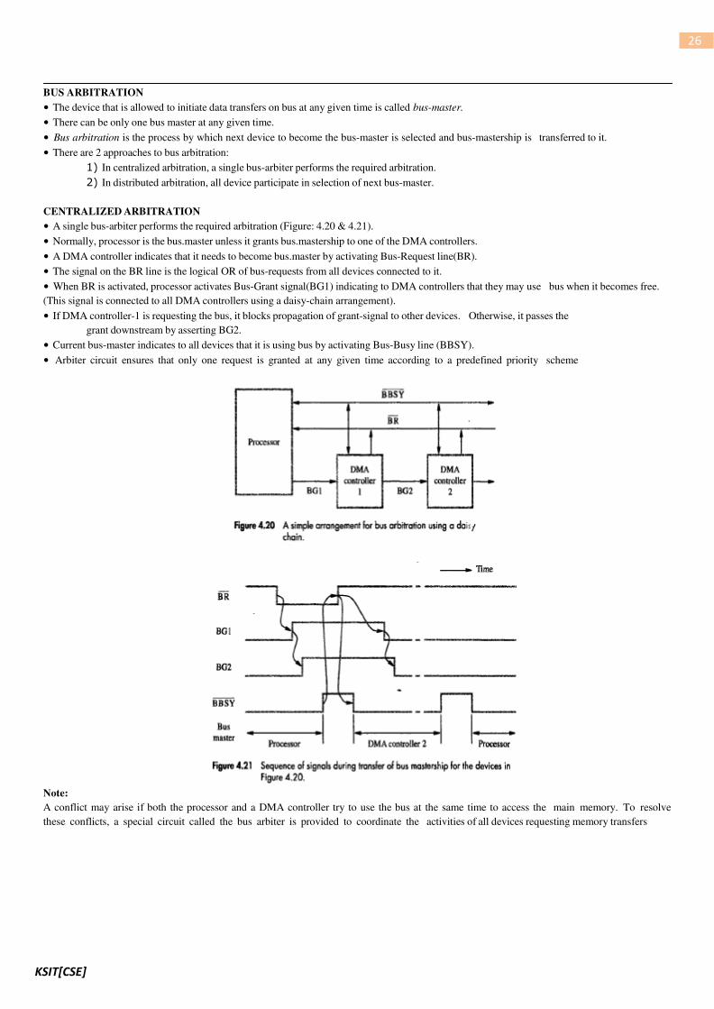
CENTRALIZED ARBITRATION
• A single bus-arbiter performs the required arbitration (Figure: 4.20 & 4.21).
• Normally, processor is the bus.master unless it grants bus.mastership to one of the DMA controllers.
• A DMA controller indicates that it needs to become bus.master by activating Bus-Request line(BR).
• The signal on the BR line is the logical OR of bus-requests from all devices connected to it.
• When BR is activated, processor activates Bus-Grant signal(BG1) indicating to DMA controllers that they may use bus when it becomes free.
(This signal is connected to all DMA controllers using a daisy-chain arrangement).
• If DMA controller-1 is requesting the bus, it blocks propagation of grant-signal to other devices. Otherwise, it passes the
grant downstream by asserting BG2.
• Current bus-master indicates to all devices that it is using bus by activating Bus-Busy line (BBSY).
• Arbiter circuit ensures that only one request is granted at any given time according to a predefined priority scheme
Note:
A conflict may arise if both the processor and a DMA controller try to use the bus at the same time to access the main memory. To resolve
these conflicts, a special circuit called the bus arbiter is provided to coordinate the activities of all devices requesting memory transfers

KSIT[CSE]
27
DISTRIBUTED ARBITRATION
• All device participate in the selection of next bus-master (Figure 4.22)
• Each device on bus is assigned a 4-bit identification number (ID).
• When 1 or more devices request bus, they
→ assert Start-Arbitration signal &
→ place their 4-bit ID numbers on four open-collector lines ARB 0 through ARB 3 .
• A winner is selected as a result of interaction among signals transmitted over these lines by all contenders.
• Net outcome is that the code on 4 lines represents request that has the highest ID number.
• Main advantage: This approach offers higher reliability since operation of bus is not dependent on any single device.

KSIT[CSE]
28
BUSES
• Bus
→ is used to inter-connect main-memory, processor & I/O devices
→ includes lines needed to support interrupts & arbitration
• Primary function: To provide a communication-path for transfer of data.
• Bus protocol is set of rules that govern the behavior of various devices connected to the buses.
• Bus-protocol specifies parameters such as:
→ asserting control-signals
→ timing of placing information on bus
→ rate of data-transfer
• A typical bus consists of 3 sets of lines: 1) Address, 2) Data and 3) Control lines.
• Control-signals specify whether a read or a write operation is to be performed.
• R/W line specifies
→ read operation when R/W=1
→ write operation when R/W=0
• In data-transfer operation, one device plays the role of a bus-master which initiates data transfers by issuing Read or Write commands on
bus ( Hence it may be called an initiator).
• Device addressed by master is referred to as a slave (or target).
• Timing of data transfers over a bus is classified into 2 types:
1) Synchronous and 2) Asynchronous
SYNCHRONOUS BUS
• All devices derive timing-information from a common clock-line.
• Equally spaced pulses on this line define equal time intervals.
• Each of these intervals constitutes a bus-cycle during which one data transfer can take place.
A sequence of events during a read operation:
• At time t0, the master (processor)
→ places the device-address on address-lines &
→ sends an appropriate command on control-lines (Figure 4.23).
• Information travels over bus at a speed determined by its physical & electrical characteristics.
• Clock pulse width(t1-t0) must be longer than the maximum propagation-delay between 2 devices connected to bus.
• Information on bus is unreliable during the period t0 to t1 because signals are changing state.
• Slave places requested input-data on data-lines at time t1.
• At end of clock cycle(at time t2), master strobes(captures) data on data-lines into its input-buffer
• For data to be loaded correctly into any storage device (such as a register built with flip-flops), data must be available at input of that
device for a period greater than setup-time of device.
KSIT[CSE]
29
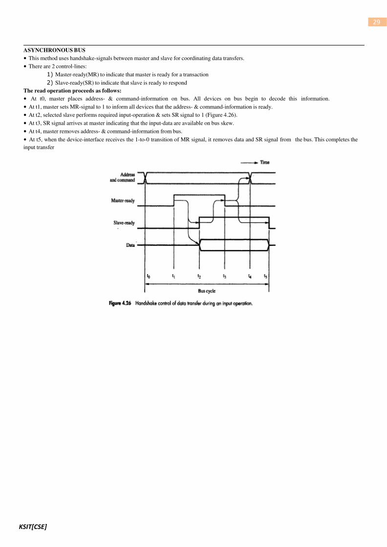
ASYNCHRONOUS BUS
• This method uses handshake-signals between master and slave for coordinating data transfers.
• There are 2 control-lines:
1) Master-ready(MR) to indicate that master is ready for a transaction
2) Slave-ready(SR) to indicate that slave is ready to respond
The read operation proceeds as follows:
• At t0, master places address- & command-information on bus. All devices on bus begin to decode this information.
• At t1, master sets MR-signal to 1 to inform all devices that the address- & command-information is ready.
• At t2, selected slave performs required input-operation & sets SR signal to 1 (Figure 4.26).
• At t3, SR signal arrives at master indicating that the input-data are available on bus skew.
• At t4, master removes address- & command-information from bus.
• At t5, when the device-interface receives the 1-to-0 transition of MR signal, it removes data and SR signal from the bus. This completes the
input transfer

KSIT[CSE]
30


![BOYMOR.QLE QL.REP] - Stacksxk898wv6983/xk898wv6983.pdf · 15 jun 1978 6:55 boymor.qle ql,rep] page 1-1 (cont.) (cont.) (cont.) (cont.) (cont.) (cont.) prover prover (cont.) 5 comment](https://img.pdfslide.us/doc/110x75/6057337242a55f07515b3baa/qlrep-stacks-xk898wv6983xk898wv6983pdf-15-jun-1978-655-boymorqle-qlrep.jpg)


![EES KissSoft Programs for Machine Design Brochure [2010]](https://img.pdfslide.us/doc/110x75/5475f538b4af9f9d0a8b5e5f/ees-kisssoft-programs-for-machine-design-brochure-2010.jpg)