Embed Size (px)
Citation preview
Unit: 2 (Circuit interrupting devices)
Basic fuse terminology:
Fuse: A fuse is a short piece of metal, inserted in the circuit, which melts when excessive
current flows through it and thus break the circuit.
Fuse elements: The most commonly used materials for fuse element are lead, tin, copper,
zinc and silver.
Rated current: It is the current which the fuse element can normally carry without
overheating or melting.
Fusing current: It is the minimum current at which the fuse element melts and thus
disconnects the circuit protected by it.
Fusing factor: It is the ratio of minimum fusing current to the current rating of the fuse
element.
Fusing factor = 𝑴𝒊𝒏𝒊𝒎𝒖𝒎 𝒇𝒖𝒔𝒊𝒏𝒈 𝒄𝒖𝒓𝒓𝒆𝒏𝒕
𝑪𝒖𝒓𝒓𝒆𝒏𝒕 𝒓𝒂𝒕𝒊𝒏𝒈 𝒐𝒇 𝒇𝒖𝒔𝒆
Prospective current: It is the r.m.s. value of the first loop of the fault current obtained if
the fuse is replaced by an ordinary conductor of negligible resistance.
Cut-off current: It is the maximum value of fault current actually reached before the fuse
melts.
Pre-arcing time: It is the time between the commencement of fault and the instant when
cut off occurs.
Arcing time: this is the time between the end of pre-arcing time and the instant when the
arc is extinguished.
Total operating time: It is the sum of pre-arcing and arcing time.
Rupturing capacity: It is the r.m.s. value of a.c. component of maximum prospective
current that a fuse can deal with at rated service voltage.
Fuse characteristics: (i) Low melting point
(ii) High conductivity
(iii) Free from deterioration due to oxidation
(iv) Low cost
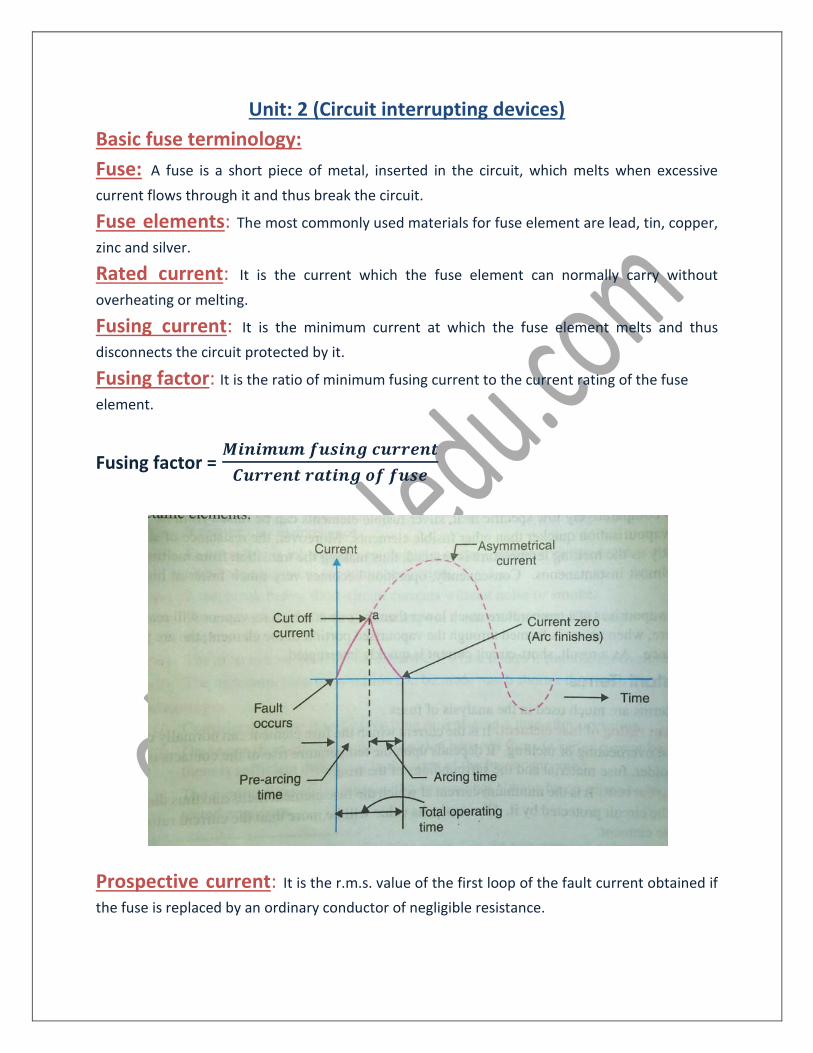
HRC Fuse: HRC Fuse consists of heat resisting ceramic body having metal end caps
on which silver current carrying element is welded in a special manner.
The fuse elements have a portion of Tin Alloy, known as a Eutectic Material. This alloy is used to give the fuse specific operating characteristics. Also, constrictions in the fuse element are provided which play a very vital role in the operation of Fuse. The space between the bodies surrounding the Fuse element is filled filling powder such as with Silica Send, Chalk, plaster of perish etc
Working Principle of HRC Fuse: Under normal operating conditions the current flowing through the Fuse element does not provide enough energy to melt the element. The heat produced is absorbed by the surrounding filling powder. If a large current flows the energy produced melts and vaporizes the fuse element before the fault current reaches the peak. The chemical reaction between the fuse element vapour and filling powder results into high resistance material which helps in extinguishing the arc.
Advantages: (i) The H.R.C. fuse is able to clear heavy faults safely. (ii) Low temperature rise at full load. (iii) They do not require maintenance. (iv) It protects the large industrial load.
Disadvantages: (i) It is more expensive than the re-wire-able or cartridge fuse. (ii) Most uneconomical as the whole unit will have to be replaced after blowing the fuse
wire.
Circuit Breaker
Circuit Breaker: The circuit breaker is a protective device which can make or break a
circuit either manually or by remote control under normal condition, break a circuit
automatically under fault condition.
Operating Principle:
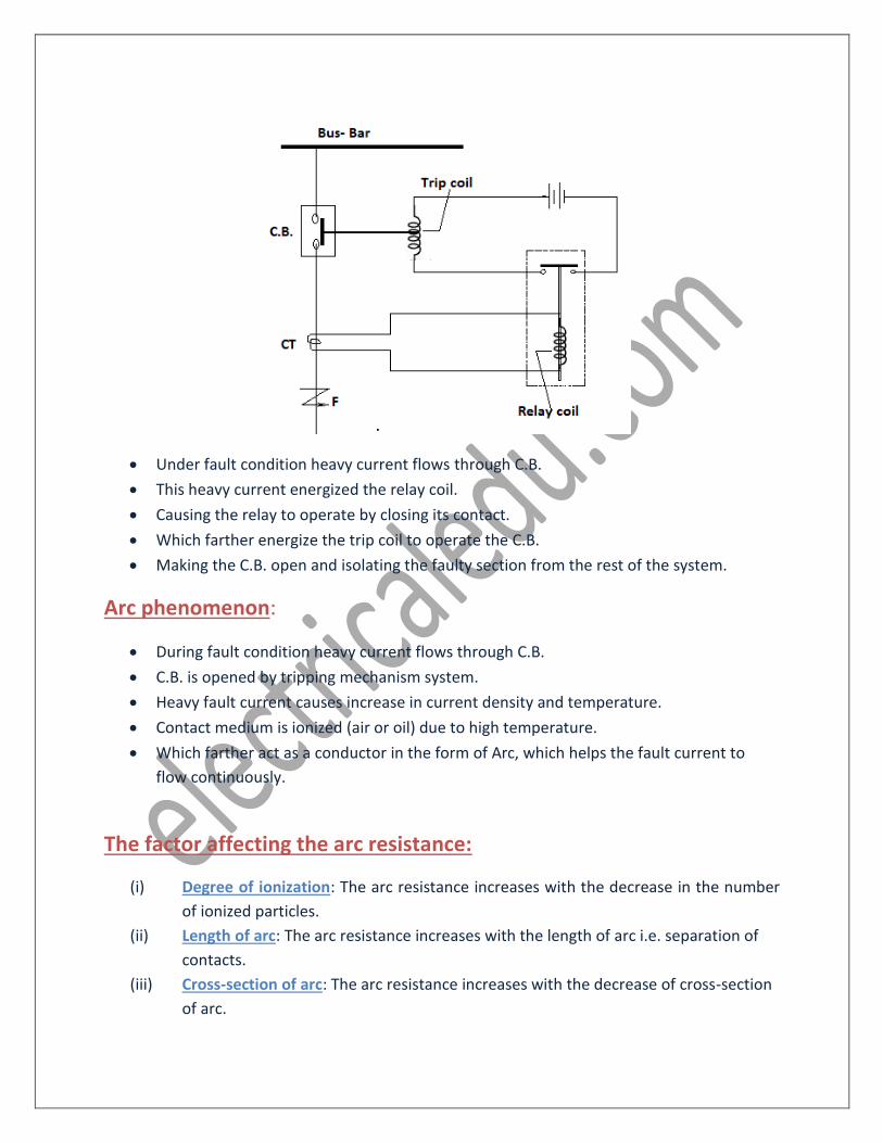
• Under fault condition heavy current flows through C.B.
• This heavy current energized the relay coil.
• Causing the relay to operate by closing its contact.
• Which farther energize the trip coil to operate the C.B.
• Making the C.B. open and isolating the faulty section from the rest of the system.
Arc phenomenon:
• During fault condition heavy current flows through C.B.
• C.B. is opened by tripping mechanism system.
• Heavy fault current causes increase in current density and temperature.
• Contact medium is ionized (air or oil) due to high temperature.
• Which farther act as a conductor in the form of Arc, which helps the fault current to
flow continuously.
The factor affecting the arc resistance:
(i) Degree of ionization: The arc resistance increases with the decrease in the number
of ionized particles.
(ii) Length of arc: The arc resistance increases with the length of arc i.e. separation of
contacts.
(iii) Cross-section of arc: The arc resistance increases with the decrease of cross-section
of arc.
Principle of arc extinction: The factors responsible to maintain the arc are.
(i) Potential difference between the contact
(ii) Ionized particle between the contacts.
Method of arc extinction:
(i) High resistance method
(ii) Low resistance method
High resistance method: In this method resistance is increased with the time so that
current is insufficient to maintain the arc. The resistance of the arc may be increased by
(i) Increasing the arc length
(ii) Cooling the arc
(iii) Reducing cross-section area
(iv) Splitting the arc
Low resistance method:
• In an a.c. system current drops to zero after every half cycle. At every current zero the
arc extinguishes for a brief moment.
• Due to re-striking voltage the dielectric strength of the medium is broken down and arc
will continue for next half cycle.
• If the dielectric strength is build up more rapidly at current zero, arc fails to re-strike
and current will be interrupted. This can be achieved by
(i) Increasing the gap between contacts
(ii) Increasing the pressure
(iii) Cooling the medium
(iv) Blast effect
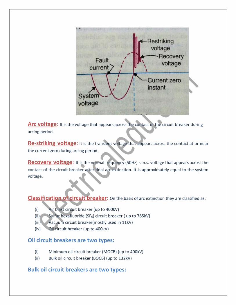
Arc voltage: It is the voltage that appears across the contact of the circuit breaker during
arcing period.
Re-striking voltage: It is the transient voltage that appears across the contact at or near
the current zero during arcing period.
Recovery voltage: It is the normal frequency (50Hz) r.m.s. voltage that appears across the
contact of the circuit breaker after final arc extinction. It is approximately equal to the system
voltage.
Classification of circuit breaker: On the basis of arc extinction they are classified as:
(i) Air blast circuit breaker (up to 400kV)
(ii) Sulfur hexafluoride (SF6) circuit breaker ( up to 765kV)
(iii) Vacuum circuit breaker(mostly used in 11kV)
(iv) Oil circuit breaker (up to 400kV)
Oil circuit breakers are two types:
(i) Minimum oil circuit breaker (MOCB) (up to 400kV)
(ii) Bulk oil circuit breaker (BOCB) (up to 132kV)
Bulk oil circuit breakers are two types:
(i) Plain break oil C.B.
(ii) Arc control oil C.B.
Arc control oil circuit breakers are two types:
(i) Force blast oil C.B.
(ii) Self blast oil C.B.
Self blast oil circuit breakers are three types:
(i) Plain explosion pot
(ii) Cross jet explosion pot
(iii) Self compensated explosion pot
Plain Break oil circuit breaker
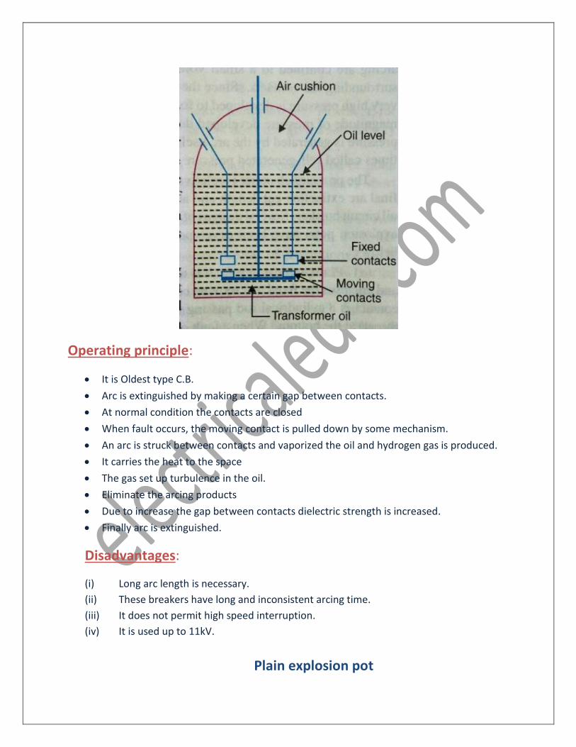
Operating principle:
• It is Oldest type C.B.
• Arc is extinguished by making a certain gap between contacts.
• At normal condition the contacts are closed
• When fault occurs, the moving contact is pulled down by some mechanism.
• An arc is struck between contacts and vaporized the oil and hydrogen gas is produced.
• It carries the heat to the space
• The gas set up turbulence in the oil.
• Eliminate the arcing products
• Due to increase the gap between contacts dielectric strength is increased.
• Finally arc is extinguished.
Disadvantages:
(i) Long arc length is necessary.
(ii) These breakers have long and inconsistent arcing time.
(iii) It does not permit high speed interruption.
(iv) It is used up to 11kV.
Plain explosion pot
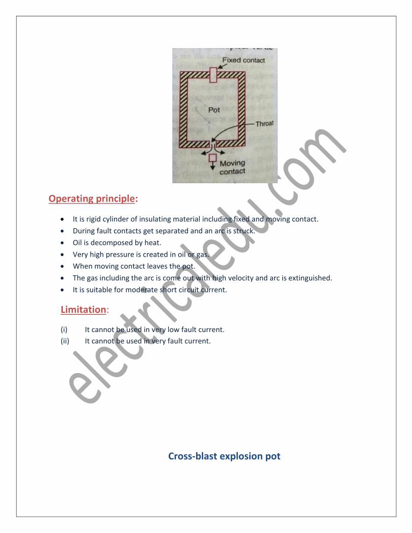
Operating principle:
• It is rigid cylinder of insulating material including fixed and moving contact.
• During fault contacts get separated and an arc is struck.
• Oil is decomposed by heat.
• Very high pressure is created in oil or gas.
• When moving contact leaves the pot.
• The gas including the arc is come out with high velocity and arc is extinguished.
• It is suitable for moderate short circuit current.
Limitation:
(i) It cannot be used in very low fault current.
(ii) It cannot be used in very fault current.
Cross-blast explosion pot
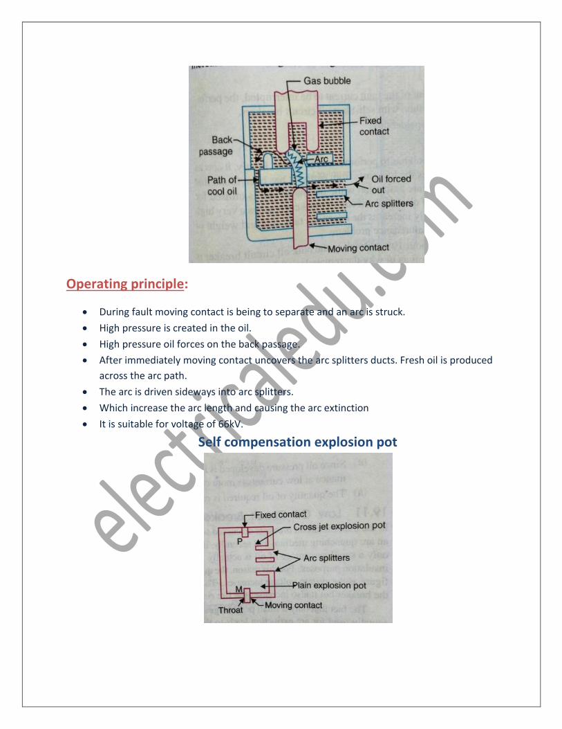
Operating principle:
• During fault moving contact is being to separate and an arc is struck.
• High pressure is created in the oil.
• High pressure oil forces on the back passage.
• After immediately moving contact uncovers the arc splitters ducts. Fresh oil is produced
across the arc path.
• The arc is driven sideways into arc splitters.
• Which increase the arc length and causing the arc extinction
• It is suitable for voltage of 66kV.
Self compensation explosion pot
Operating principle:
• It can interrupt low as well as heavy short circuit current
• It consists of two chambers, upper chamber is cross-jet explosion pot and lower
chamber is plain explosion pot.
• During heavy short circuit it behaves as a cross-jet explosion pot.
• On low short circuit current, the rate of gas generation is small.
• The moving contact will take the time to reach the lower chamber.
• During this time gas builds up sufficient pressure.
• When the moving contact comes out of the throat, the arc is extinguished by plain
explosion pot.
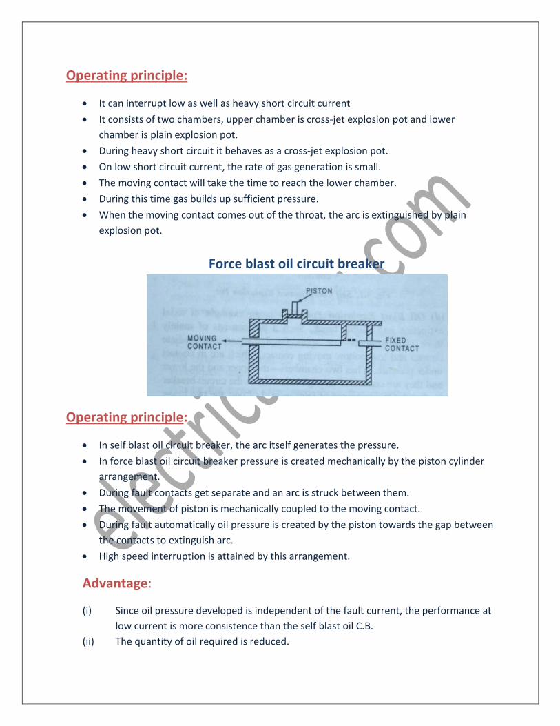
Force blast oil circuit breaker
Operating principle:
• In self blast oil circuit breaker, the arc itself generates the pressure.
• In force blast oil circuit breaker pressure is created mechanically by the piston cylinder
arrangement.
• During fault contacts get separate and an arc is struck between them.
• The movement of piston is mechanically coupled to the moving contact.
• During fault automatically oil pressure is created by the piston towards the gap between
the contacts to extinguish arc.
• High speed interruption is attained by this arrangement.
Advantage:
(i) Since oil pressure developed is independent of the fault current, the performance at
low current is more consistence than the self blast oil C.B.
(ii) The quantity of oil required is reduced.
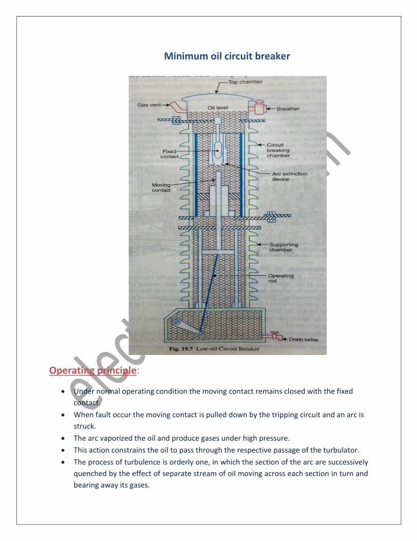
Minimum oil circuit breaker
Operating principle:
• Under normal operating condition the moving contact remains closed with the fixed
contact.
• When fault occur the moving contact is pulled down by the tripping circuit and an arc is
struck.
• The arc vaporized the oil and produce gases under high pressure.
• This action constrains the oil to pass through the respective passage of the turbulator.
• The process of turbulence is orderly one, in which the section of the arc are successively
quenched by the effect of separate stream of oil moving across each section in turn and
bearing away its gases.
Advantage: (i) It requires less quantity oil.
(ii) It requires smaller space.
(iii) There is reduced risk of fire.
(iv) Maintenance problem is reduced.
Disadvantage:
(i) Due to small quantity of oil the degree of carbonization is increased.
(ii) There is a difficulty of removing the gases from the contact space in time.
(iii) The dielectric strength of the oil deteriorates rapidly.
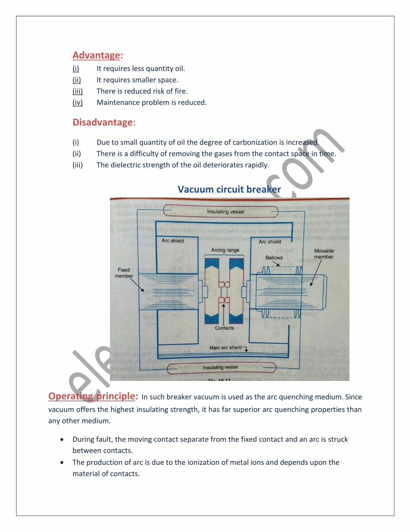
Vacuum circuit breaker
Operating principle: In such breaker vacuum is used as the arc quenching medium. Since
vacuum offers the highest insulating strength, it has far superior arc quenching properties than
any other medium.
• During fault, the moving contact separate from the fixed contact and an arc is struck
between contacts.
• The production of arc is due to the ionization of metal ions and depends upon the
material of contacts.
• The arc is quickly extinguished because of the metallic vapour, electrons and ions.
• Since vacuum has very fast rate of recovery of dielectric strength, the arc extinction in
vacuum occurs with short contact separation.
Advantage: (i) They are compact, reliable and have longer life.
(ii) There are no fire hazards.
(iii) There is no generation of gas during and after operation.
(iv) They require little maintenance.
(v) They can successfully withstand lightning surges.
(vi) It is used up to 66kV.
Air blast circuit breaker
Operating principle:
• These breakers employ a high pressure air (nitrogen, carbon di-oxide and hydrogen can
be used) as an arc quenching medium.
• During fault moving contact is being separated from the fixed contact.
• Air blast is established by opening of blast valve.
• The air blast cools the arc and sweeps away the arcing products to the atmosphere.
• This rapidly increases the dielectric strength of the medium between contacts and
prevents from re-establishing the arc.
• Consequently the arc is extinguished and flow of current is interrupted.
• The different types of air blast circuit breakers are:
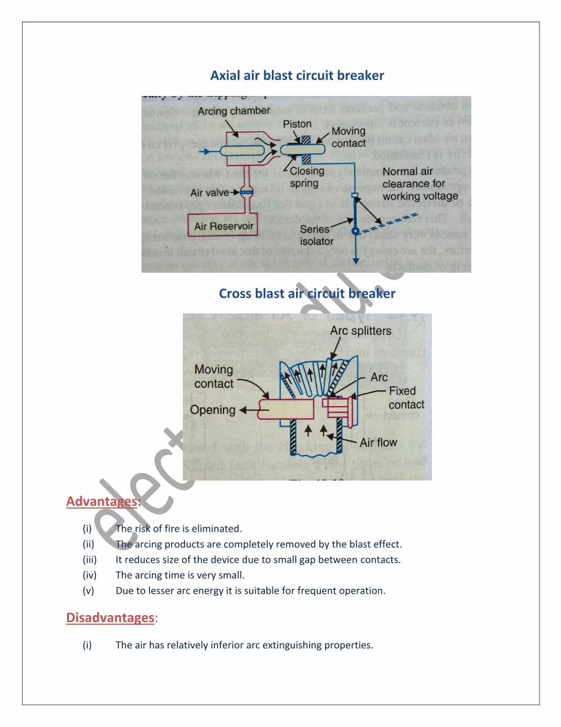
Axial air blast circuit breaker
Cross blast air circuit breaker
Advantages:
(i) The risk of fire is eliminated.
(ii) The arcing products are completely removed by the blast effect.
(iii) It reduces size of the device due to small gap between contacts.
(iv) The arcing time is very small.
(v) Due to lesser arc energy it is suitable for frequent operation.
Disadvantages:
(i) The air has relatively inferior arc extinguishing properties.
(ii) Considerable maintenance is required for the compressor plant which supplies the
air blast.
(iii) There is a difficulty of removing the gases from the contact space in time.
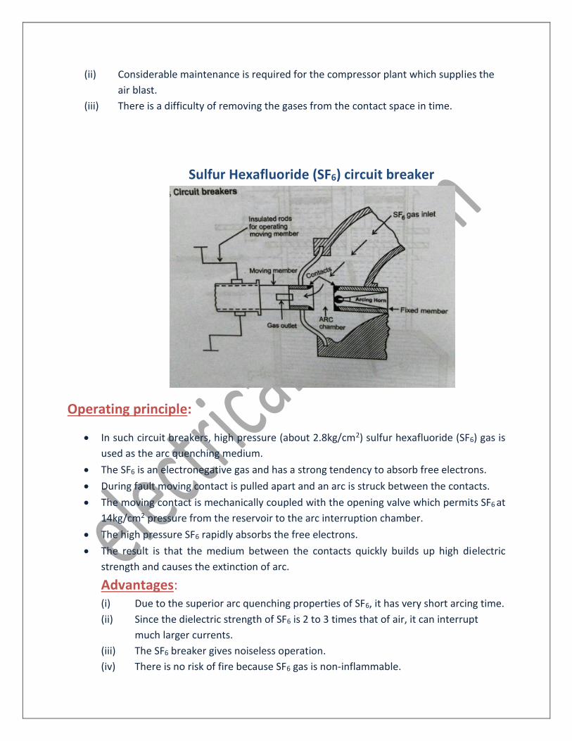
Sulfur Hexafluoride (SF6) circuit breaker
Operating principle:
• In such circuit breakers, high pressure (about 2.8kg/cm2) sulfur hexafluoride (SF6) gas is
used as the arc quenching medium.
• The SF6 is an electronegative gas and has a strong tendency to absorb free electrons.
• During fault moving contact is pulled apart and an arc is struck between the contacts.
• The moving contact is mechanically coupled with the opening valve which permits SF6 at
14kg/cm2 pressure from the reservoir to the arc interruption chamber.
• The high pressure SF6 rapidly absorbs the free electrons.
• The result is that the medium between the contacts quickly builds up high dielectric
strength and causes the extinction of arc.
Advantages: (i) Due to the superior arc quenching properties of SF6, it has very short arcing time.
(ii) Since the dielectric strength of SF6 is 2 to 3 times that of air, it can interrupt
much larger currents.
(iii) The SF6 breaker gives noiseless operation.
(iv) There is no risk of fire because SF6 gas is non-inflammable.
(v) It is used up to 765kV
Disadvantages:
(i) SF6 breakers are costly due to high cost of SF6.
(ii) Since SF6 gas has to be reconditioned after every operation of breaker, additional
equipment is required for this purpose.
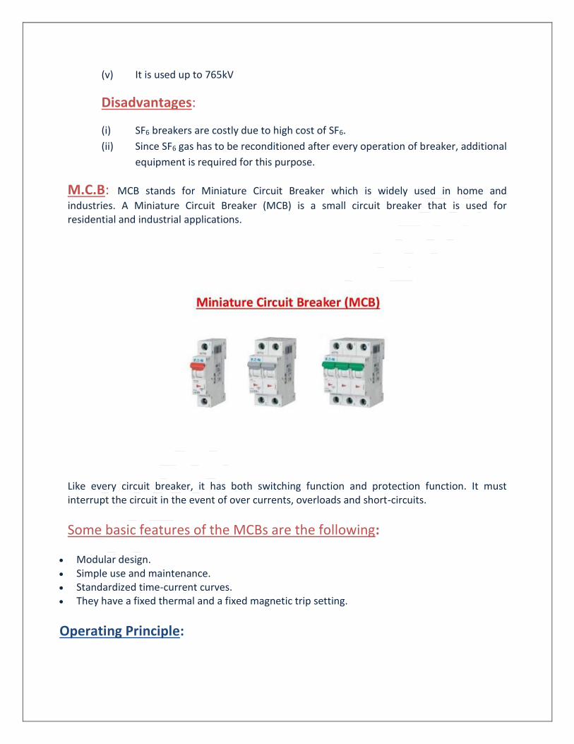
M.C.B: MCB stands for Miniature Circuit Breaker which is widely used in home and
industries. A Miniature Circuit Breaker (MCB) is a small circuit breaker that is used for residential and industrial applications.
Like every circuit breaker, it has both switching function and protection function. It must interrupt the circuit in the event of over currents, overloads and short-circuits.
Some basic features of the MCBs are the following:
• Modular design. • Simple use and maintenance. • Standardized time-current curves. • They have a fixed thermal and a fixed magnetic trip setting.
Operating Principle:
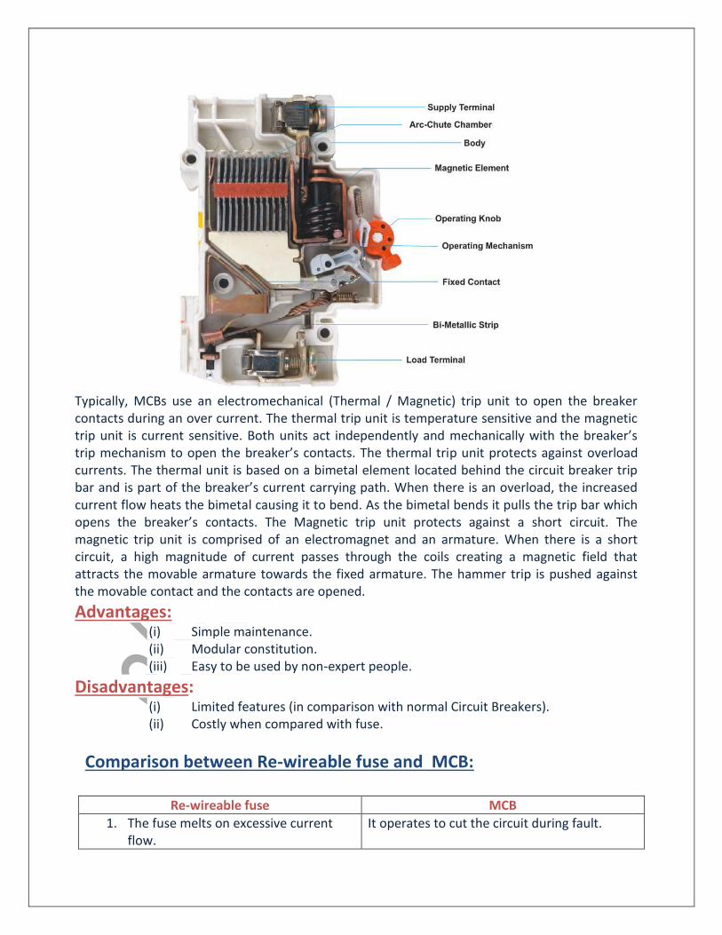
Typically, MCBs use an electromechanical (Thermal / Magnetic) trip unit to open the breaker contacts during an over current. The thermal trip unit is temperature sensitive and the magnetic trip unit is current sensitive. Both units act independently and mechanically with the breaker’s trip mechanism to open the breaker’s contacts. The thermal trip unit protects against overload currents. The thermal unit is based on a bimetal element located behind the circuit breaker trip bar and is part of the breaker’s current carrying path. When there is an overload, the increased current flow heats the bimetal causing it to bend. As the bimetal bends it pulls the trip bar which opens the breaker’s contacts. The Magnetic trip unit protects against a short circuit. The magnetic trip unit is comprised of an electromagnet and an armature. When there is a short circuit, a high magnitude of current passes through the coils creating a magnetic field that attracts the movable armature towards the fixed armature. The hammer trip is pushed against the movable contact and the contacts are opened.
Advantages: (i) Simple maintenance. (ii) Modular constitution. (iii) Easy to be used by non-expert people.
Disadvantages: (i) Limited features (in comparison with normal Circuit Breakers). (ii) Costly when compared with fuse.
Comparison between Re-wireable fuse and MCB:
Re-wireable fuse MCB
1. The fuse melts on excessive current flow.
It operates to cut the circuit during fault.
2. The fuse wire available at the time of rewiring may not be standard rating.
These are available in standard rating
3. It is cheapest in cost It is very costly
4. It deteriorates with time It does not deteriorate with time
5. A fuse need repairs and fuse wire is to be replaced after it is melt.
A MCB needs no repair and there is no replacement of any parts.
Isolator: Isolators are disconnecting switches which can be used for disconnecting a circuit
under no load condition. They are generally used along with a circuit breaker. An isolator can be
opened only after the circuit breaker. They are two types:
(i) Single pole isolator
(ii) Three pole isolator
Earth switch/Earth isolator: Earth switch is connected between the line conductor
and earth. Normally it is open. When the line is disconnected the earth switch is closed so as to
discharge the voltage trapped on the line. Normally earth switch is mounted on the frame of
isolator.
Sequence of operation of Isolator, Circuit breaker and Earth switch:
While opening:
(i) Open Circuit breaker
(ii) Open Isolator
(iii) Closed Earth switch
While Closing:
(i) Ensure Circuit breaker is open
(ii) Open Earth switch
(iii) Close Isolator
(iv) Close Circuit breaker
Autorecloser: In electric power distribution, a recloser or autorecloser is a circuit breaker
that can automatically close after it has been opened due to a fault. Reclosers are used on
overhead distribution systems to detect and interrupt momentary faults. Since many short-
circuit on overhead lines clear
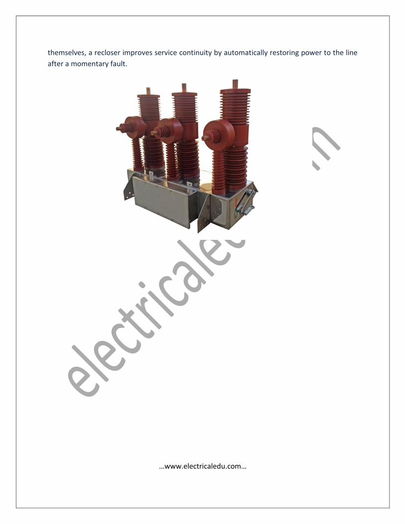
themselves, a recloser improves service continuity by automatically restoring power to the line
after a momentary fault.
…www.electricaledu.com…