Embed Size (px)
Citation preview
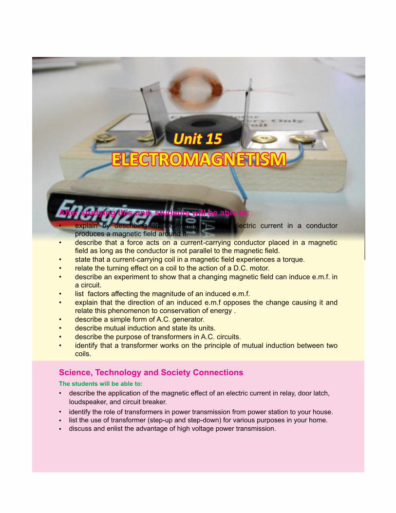
Unit 15Unit 15Unit 15
• explain by describing an experiment that an electric current in a conductor produces a magnetic field around it.
• describe that a force acts on a current -carrying conductor placed in a magnetic field as long as the conductor is not parallel to the magnetic field.
• state that a current-carrying coil in a magnetic field experiences a torque. • relate the turning effect on a coil to the action of a D.C. motor. • describe an experiment to show that a changing magnetic field can induce e.m.f. in
a circuit. • list factors affecting the magnitude of an induced e.m.f. • explain that the direction of an induced e.m.f opposes the change causing it and
relate this phenomenon to conservation of energy . • describe a simple form of A.C. generator. • describe mutual induction and state its units. • describe the purpose of transformers in A.C. circuits. • identify that a transformer works on the principle of mutual induction between two
coils.
ELECTROMAGNETISM ELECTROMAGNETISM ELECTROMAGNETISM
After this students will be able to:studying unit,
• describe the application of the magnetic effect of an electric current in relay, door latch,
loudspeaker, and circuit breaker.
Science, Technology and Society Connections
identify the role of transformers in power transmission from power station to your house.
The students will be able to:
•
••
list the use of transformer (step-up and step-down) for various purposes in your home.discuss and enlist the advantage of high voltage power transmission.
ELECTROMAGNETISM
Interesting informationElectr ic charges can be separated into a single type. For example, you can have a single negative charge or a single positive charge. Magnetic poles cannot be separated. It is not possible to have a magnetic north pole without a magnetic south pole. This is a fundamental difference between magnetism and electricity.
Electromagnetism is the study of magnetic effects of current. The use of electromagnetism in different fields of science and technology is very wide. Motors and electric meters are based on the effect of magnetism produced by the electric current in wires. Generators produce electric current due to the movement of wires near very large magnets.
15.1 MAGNETIC EFFECTS OF A STEADY CURRENT
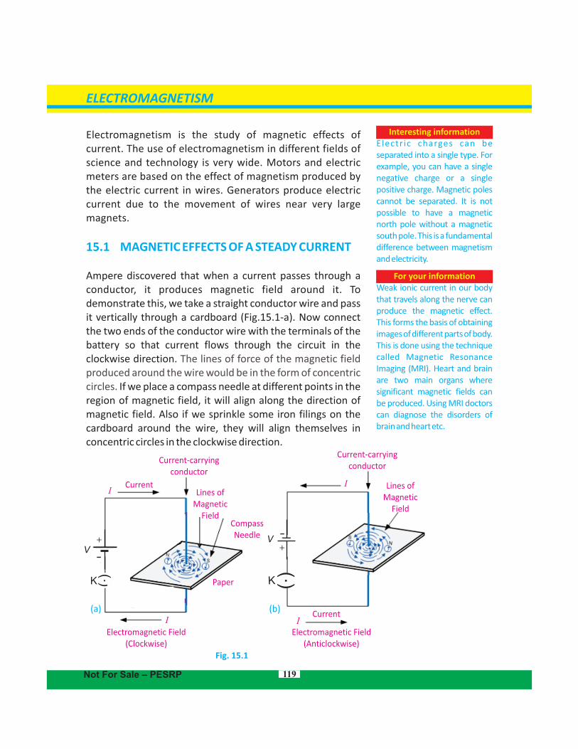
Ampere discovered that when a current passes through a conductor, it produces magnetic field around it. To demonstrate this, we take a straight conductor wire and pass it vertically through a cardboard . Now connect (Fig.15.1-a)the two ends of the conductor wire with the terminals of the battery so that current flows through the circuit in the clockwise direction. The lines of force of the magnetic field produced around the wire would be in the form of concentric circles. If we place a compass needle at different points in the region of magnetic field, it will align along the direction of magnetic field. Also if we sprinkle some iron filings on the cardboard around the wire, they will align themselves in concentric circles in the clockwise direction.
Fig. 15.1
119
For your informationWeak ionic current in our body that travels along the nerve can produce the magnetic effect. This forms the basis of obtaining images of different parts of body. This is done using the technique called Magnetic Resonance Imaging (MRI). Heart and brain are two main organs where significant magnetic fields can be produced. Using MRI doctors can diagnose the disorders of brain and heart etc.
KK
Current-carryingconductor
CurrentLines of
MagneticField
Compass Needle
I
Paper
I
+
Electromagnetic Field(Clockwise)
(a) (b)
Electromagnetic Field(Anticlockwise)
CurrentI
+
I
Current-carryingconductor
Lines ofMagnetic
Field
Not For Sale – PESRP
V-
-V
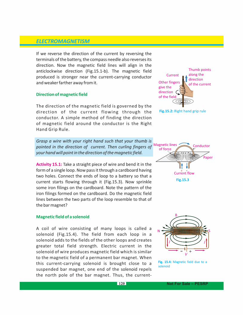
If we reverse the direction of the current by reversing the terminals of the battery, the compass needle also reverses its direction. Now the magnetic field lines will align in the anticlockwise direction (Fig.15.1-b). The magnetic field produced is stronger near the current-carrying conductor and weaker farther away from it.
Direction of magnetic field
The direction of the magnetic field is governed by the direct ion of the current f lowing through the conductor. A simple method of finding the direction of magnetic field around the conductor is the Right Hand Grip Rule.
Grasp a wire with your right hand such that your thumb is pointed in the direction of current. Then curling fingers of your hand will point in the direction of the magnetic field.
Activity 15.1: Take a straight piece of wire and bend it in the form of a single loop. Now pass it through a cardboard having two holes. Connect the ends of loop to a battery so that a current starts flowing through it (Fig.15.3). Now sprinkle some iron filings on the cardboard. Note the pattern of the iron filings formed on the cardboard. Do the magnetic field lines between the two parts of the loop resemble to that of the bar magnet?
Magnetic field of a solenoid
A coil of wire consisting of many loops is called a solenoid (Fig.15.4). The field from each loop in a solenoid adds to the fields of the other loops and creates greater total field strength. Electric current in the solenoid of wire produces magnetic field which is similar to the magnetic field of a permanent bar magnet. When this current-carrying solenoid is brought close to a suspended bar magnet, one end of the repels solenoidthe north pole of the bar magnet. Thus, the current-
120
Fig.15.3
Fig.15.2: Right hand grip rule
Thumb points along thedirection of the current
Current
Other fingers give the direction of the field
Conductor Magnetic linesof force
Paper
Current flow
ELECTROMAGNETISM
Not For Sale – PESRP
B
N S
II
+V
-
Fig. 15.4: Magnetic field due to a solenoid
121
Electriccurrent
Iron core
Coil magnet
Bar magnet
N
N
S
S
ELECTROMAGNETISM
Not For Sale – PESRP
FB B+
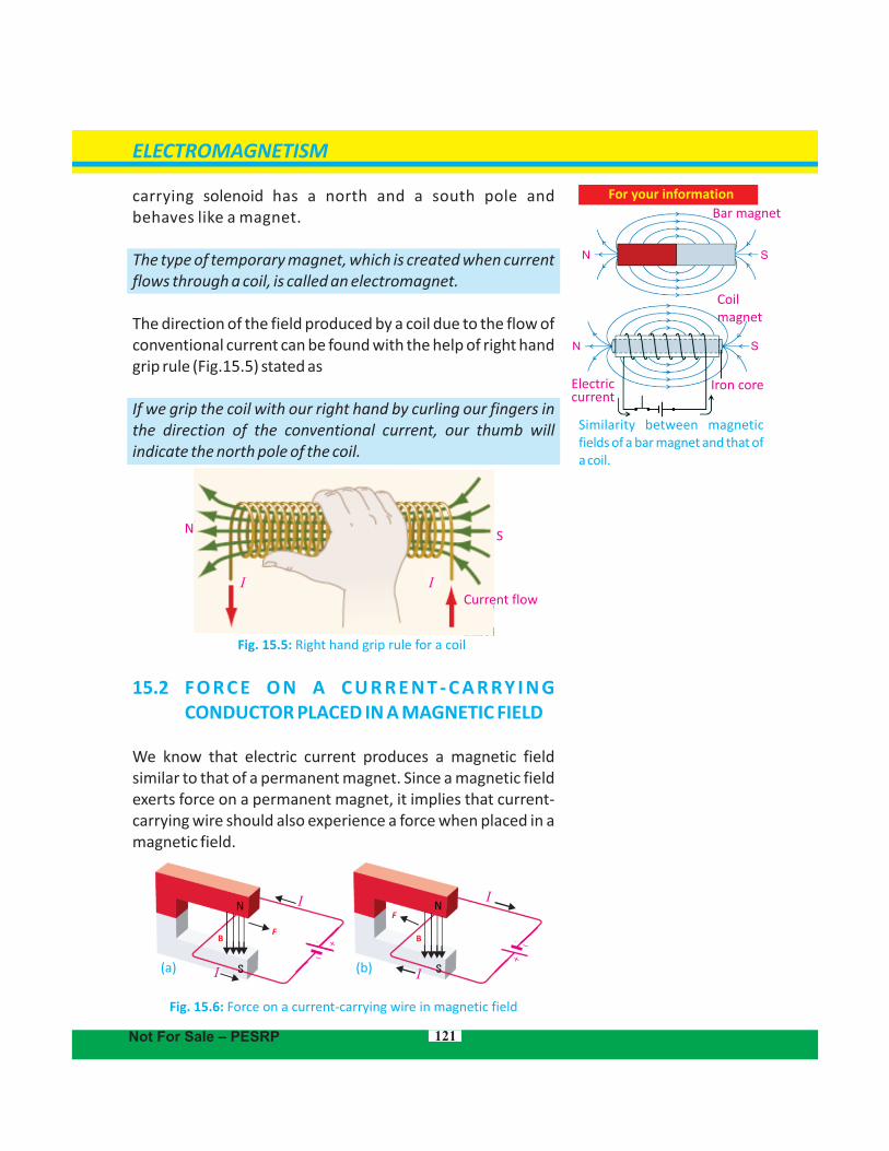
carrying has a north and a south pole and solenoidbehaves like a magnet.
The type of temporary magnet, which is created when current flows through a coil, is called an electromagnet.
The direction of the field produced by a coil due to the flow of conventional current can be found with the help of right hand grip rule (Fig.15.5) stated as
If we grip the coil with our right hand by curling our fingers in the direction of the conventional current, our thumb will indicate the north pole of the coil.
Fig. 15.5: Right hand grip rule for a coil
15.2 F O R C E O N A C U R R E N T - C A R RY I N G CONDUCTOR PLACED IN A MAGNETIC FIELD
We know that electric current produces a magnetic field similar to that of a permanent magnet. Since a magnetic field exerts force on a permanent magnet, it implies that current-carrying wire should also experience a force when placed in a magnetic field.
(a) (b)
Fig. 15.6: Force on a current-carrying wire in magnetic field
F
– +
–
SN
I ICurrent flow
For your information
Similarity between magnetic fields of a bar magnet and that of a coil.
I
II
I
The force on a wire in a magnetic field can be demonstrated using the arrangement shown in Fig. 15.6. A battery produces current in a wire placed inside the magnetic field of a permanent magnet. Current-carrying wire produces its own magnetic field which interacts with the field of the magnet. As a result, a force is exerted on the wire. Depending on the direction of the current, the force on the wire either pushes or pulls it towards right (Fig. 15.6-a) or towards left (Fig.15.6-b).
Michael Faraday discovered that the force on the wire is at right angles to both the direction of the magnetic field and the direction of the current. The force is increased if
The current in the wire is increased
Strength of magnetic field is increased
The length of the wire inside the magnetic field is increased
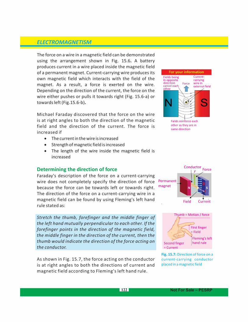
Determining the direction of forceFaraday's description of the force on a current-carrying wire does not completely specify the direction of force because the force can be towards left or towards right. The direction of the force on a current-carrying wire in a magnetic field can be found by using Fleming's left hand rule stated as:
Stretch the thumb, forefinger and the middle finger of the left hand mutually perpendicular to each other. If the forefinger points in the direction of the magnetic field, the middle finger in the direction of the current, then the thumb would indicate the direction of the force acting on the conductor.
As shown in Fig. 15.7, the force acting on the conductor is at right angles to both the directions of current and magnetic field according to Fleming's left hand rule.
122
ELECTROMAGNETISM
Not For Sale – PESRP
Thumb = Motion / force
First finger = Field
Fleming’s lefthand ruleSecond finger
= Current
CurrentField
Permanentmagnet
Conductor Force
F
N S
Fig. 15.7: Direction of force on a current-carrying conductor placed in a magnetic field
For your information
Force
Current- carryingwire in external field
Fields being in opposite direction cancel each other
Fields reinforce eachother as they are insame direction
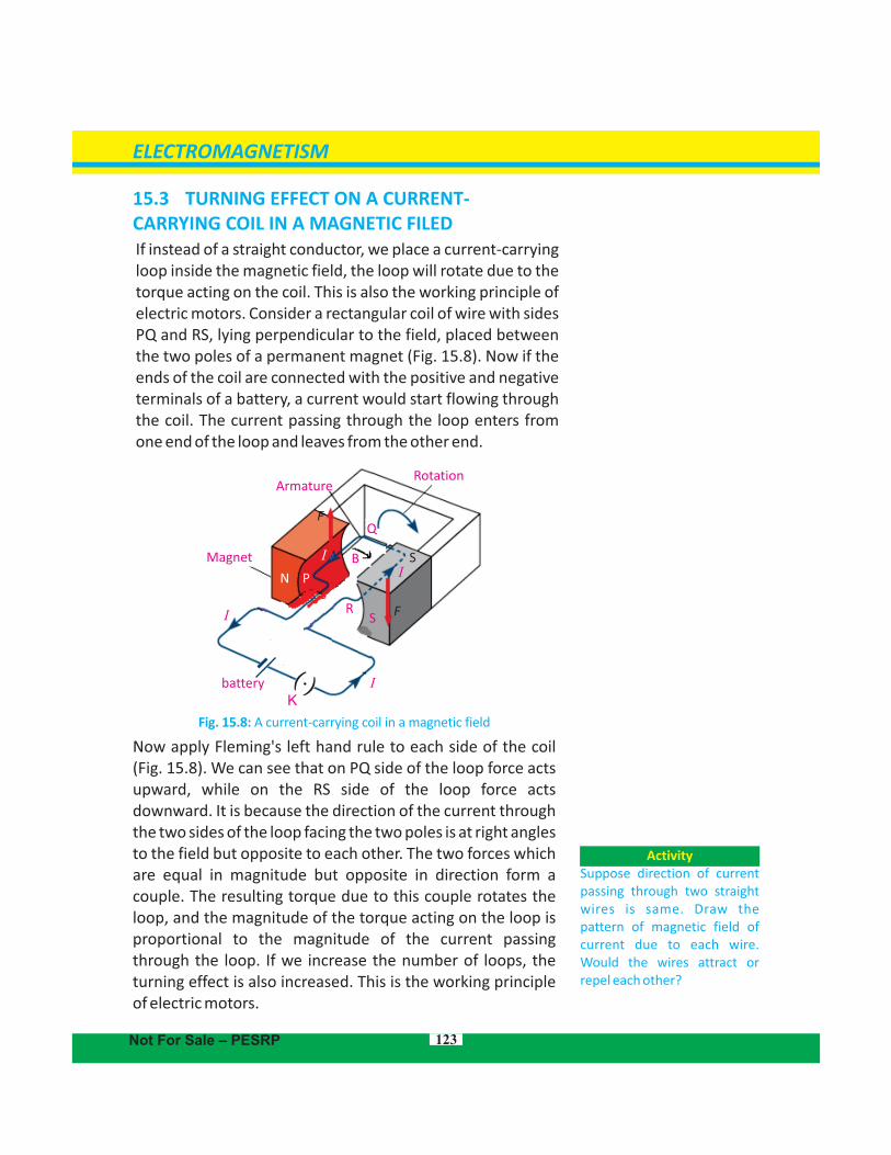
15.3 TURNING EFFECT ON A CURRENT-CARRYING COIL IN A MAGNETIC FILEDIf instead of a straight conductor, we place a current-carrying loop inside the magnetic field, the loop will rotate due to the torque acting on the coil. This is also the working principle of electric motors. Consider a rectangular coil of wire with sides PQ and RS, lying perpendicular to the field, placed between the two poles of a permanent magnet (Fig. 15.8). Now if the ends of the coil are connected with the positive and negative terminals of a battery, a current would start flowing through the coil. The current passing through the loop enters from one end of the loop and leaves from the other end.
Fig. 15.8: A current-carrying coil in a magnetic field
Now apply Fleming's left hand rule to each side of the coil (Fig. 15.8). We can see that on PQ side of the loop force acts upward, while on the RS side of the loop force acts downward. It is because the direction of the current through the two sides of the loop facing the two poles is at right angles to the field but opposite to each other. The two forces which are equal in magnitude but opposite in direction form a couple. The resulting torque due to this couple rotates the loop, and the magnitude of the torque acting on the loop is proportional to the magnitude of the current passing through the loop. If we increase the number of loops, the turning effect is also increased. This is the working principle of electric motors.
123
ELECTROMAGNETISM
Not For Sale – PESRP
ActivitySuppose direction of current passing through two straight wires is same. Draw the pattern of magnetic field of current due to each wire. Would the wires attract or repel each other?
Rotation
Kbattery
Magnet
Armature
N P
RS F
B SI
I
I
I
QF
Magnet
Brushes
Armature Rotation
CommutatorI
I
K
S
F
I
Q
N P
R
BI
F
S
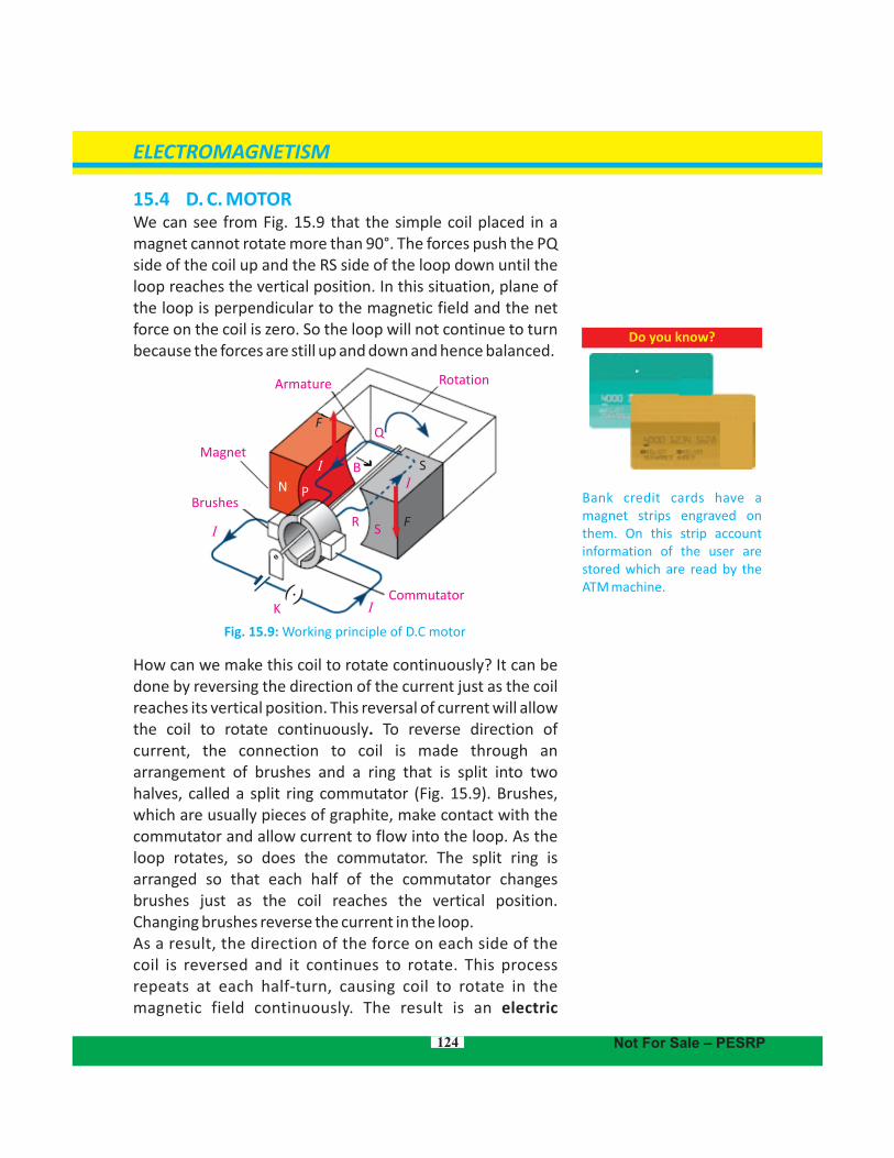
15.4 D. C. MOTOR We can see from Fig. 15.9 that the simple coil placed in a magnet cannot rotate more than 90°. The forces push the PQ side of the coil up and the RS side of the loop down until the loop reaches the vertical position. In this situation, plane of the loop is perpendicular to the magnetic field and the net force on the coil is zero. So the loop will not continue to turn because the forces are still up and down and hence balanced.
Fig. 15.9: Working principle of D.C motor
How can we make this coil to rotate continuously? It can be done by reversing the direction of the current just as the coil reaches its vertical position. This reversal of current will allow the coil to rotate continuously. To reverse direction of current, the connection to coil is made through an arrangement of brushes and a ring that is split into two halves, called a split ring commutator (Fig. 15.9). Brushes, which are usually pieces of graphite, make contact with the commutator and allow current to flow into the loop. As the loop rotates, so does the commutator. The split ring is arranged so that each half of the commutator changes brushes just as the coil reaches the vertical position. Changing brushes reverse the current in the loop.As a result, the direction of the force on each side of the coil is reversed and it continues to rotate. This process repeats at each half-turn, causing coil to rotate in the magnetic field continuously. The result is an electric
124
Do you know?
Bank credit cards have a magnet strips engraved on them. On this strip account information of the user are stored which are read by the ATM machine.
ELECTROMAGNETISM
Not For Sale – PESRP
motor, which is a device that converts electric energy into rotational kinetic energy.
In a practical electric motor, the coil, called the armature, is made of many loops mounted on a shaft or axle. The magnetic field is produced either by permanent magnets or by an electromagnet, called a field coil. The torque on the armature, and, as a result, the speed of the motor, is controlled by varying the current through the motor.The total force acting on the armature can be increased by
Increasing the number of turns of the coil
Increasing the current in the coil
Increasing the strength of the magnetic field
Increasing the area of the coil
15.5 ELECTROMAGNETIC INDUCTION
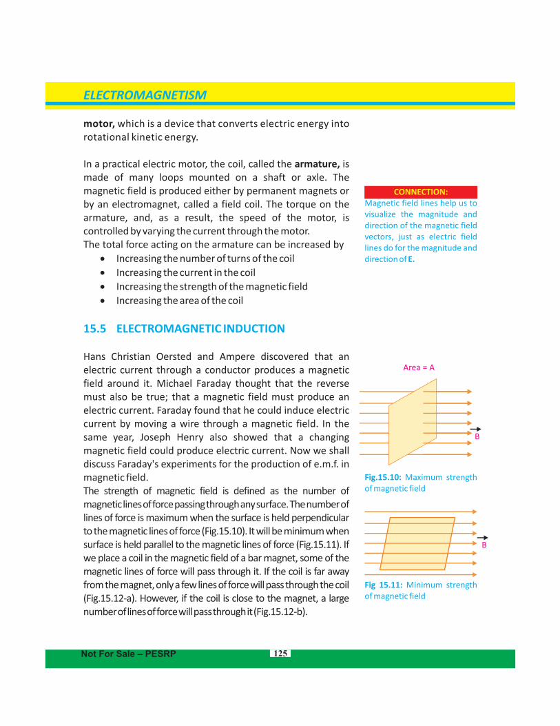
Hans Christian Oersted and Ampere discovered that an electric current through a conductor produces a magnetic field around it. Michael Faraday thought that the reverse must also be true; that a magnetic field must produce an electric current. Faraday found that he could induce electric current by moving a wire through a magnetic field. In the same year, Joseph Henry also showed that a changing magnetic field could produce electric current. Now we shall discuss Faraday's experiments for the production of e.m.f. in magnetic field. The strength of magnetic field is defined as the number of magnetic lines of force passing through any surface. The number of lines of force is maximum when the surface is held perpendicular to the magnetic lines of force (Fig.15.10). It will be minimum when surface is held parallel to the magnetic lines of force (Fig.15.11). If we place a coil in the magnetic field of a bar magnet, some of the magnetic lines of force will pass through it. If the coil is far away from the magnet, only a few lines of force will pass through the coil (Fig.15.12-a). However, if the coil is close to the magnet, a large number of lines of force will pass through it (Fig.15.12-b).
125
CONNECTION:Magnetic field lines help us to visualize the magnitude and direction of the magnetic field vectors, just as electric field lines do for the magnitude and direction of E.
ELECTROMAGNETISM
Not For Sale – PESRP
Fig 15.11: Minimum strength of magnetic field
Fig.15.10: Maximum strength of magnetic field
Area = A
B
B
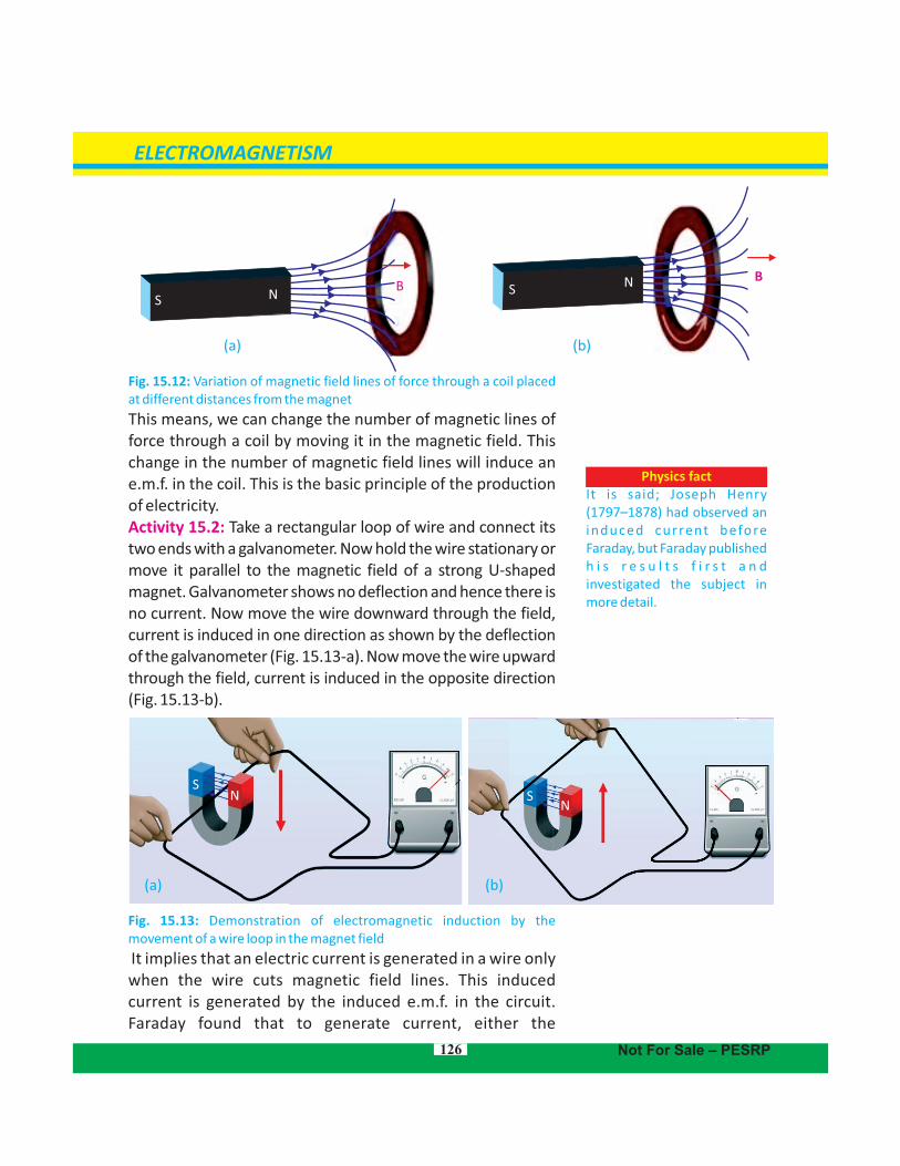
Fig. 15.12: Variation of magnetic field lines of force through a coil placed at different distances from the magnet
This means, we can change the number of magnetic lines of force through a coil by moving it in the magnetic field. This change in the number of magnetic field lines will induce an e.m.f. in the coil. This is the basic principle of the production of electricity.Activity 15.2: Take a rectangular loop of wire and connect its two ends with a galvanometer. Now hold the wire stationary or move it parallel to the magnetic field of a strong U-shaped magnet. Galvanometer shows no deflection and hence there is no current. Now move the wire downward through the field, current is induced in one direction as shown by the deflection of the galvanometer (Fig. 15.13-a). Now move the wire upward through the field, current is induced in the opposite direction (Fig. 15.13-b).
Fig. 15.13: Demonstration of electromagnetic induction by the movement of a wire loop in the magnet field
It implies that an electric current is generated in a wire only when the wire cuts magnetic field lines. This induced current is generated by the induced e.m.f. in the circuit. Faraday found that to generate current, either the
126
ELECTROMAGNETISM
(a) (b)
(a) (b)
SSN
N BB
Not For Sale – PESRP
Physics factIt is said; Joseph Henry (1797–1878) had observed an induced current before Faraday, but Faraday published h i s r e s u l t s f i r s t a n d investigated the subject in more detail.
SS
NN
conductor must move through a magnetic field or a magnetic field must change across the conductor. Thus, The process of generating an induced current in a circuit by changing the number of magnetic lines of force passing through it is called electromagnetic induction.
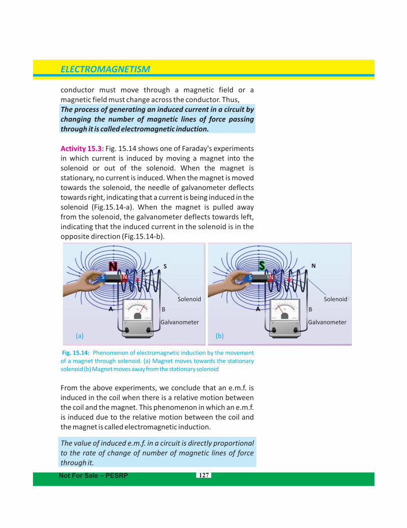
Activity 15.3: Fig. 15.14 shows one of Faraday's experiments in which current is induced by moving a magnet into the solenoid or out of the solenoid. When the magnet is stationary, no current is induced. When the magnet is moved towards the solenoid, the needle of galvanometer deflects towards right, indicating that a current is being induced in the solenoid (Fig.15.14-a). When the magnet is pulled away from the solenoid, the galvanometer deflects towards left, indicating that the induced current in the solenoid is in the opposite direction . (Fig.15.14-b)
Fig. 15.14: Phenomenon of electromagnetic induction by the movement of a magnet through solenoid. (a) Magnet moves towards the stationary solenoid (b) Magnet moves away from the stationary solenoid
From the above experiments, we conclude that an e.m.f. is induced in the coil when there is a relative motion between the coil and the magnet. This phenomenon in which an e.m.f. is induced due to the relative motion between the coil and the magnet is called electromagnetic induction.
The value of induced e.m.f. in a circuit is directly proportional to the rate of change of number of magnetic lines of force through it.
127
ELECTROMAGNETISM
Galvanometer
Solenoid
Galvanometer
Solenoid
BB
(a) (b)
S SN N
Not For Sale – PESRP
NS
This is called Faraday's law of electromagnetic induction.Factors Affecting Induced e.m.fThe magnitude of induced e.m.f. in a circuit depends on the following factors: 1. Speed of relative motion of the coil and the magnet2. Number of turns of the coil
15.6 Direction of induced e.m.f. – Lenz’s LawLenz devised a rule to find out the direction of a current induced in a circuit. It is explained from the following activity:
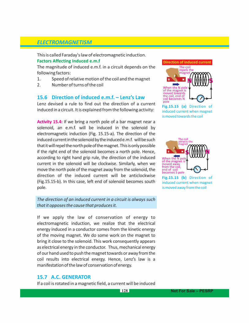
Activity 15.4: If we bring a north pole of a bar magnet near a solenoid, an e.m.f. will be induced in the solenoid by electromagnetic induction (Fig. 15.15-a). The direction of the induced current in the solenoid by the induced e.m.f. will be such that it will repel the north pole of the magnet. This is only possible if the right end of the solenoid becomes a north pole. Hence, according to right hand grip rule, the direction of the induced current in the solenoid will be clockwise. Similarly, when we move the north pole of the magnet away from the solenoid, the direction of the induced current will be anticlockwise (Fig.15.15-b). In this case, left end of solenoid becomes south pole.
The direction of an induced current in a circuit is always such that it opposes the cause that produces it.
If we apply the law of conservation of energy to electromagnetic induction, we realize that the electrical energy induced in a conductor comes from the kinetic energy of the moving magnet. We do some work on the magnet to bring it close to the solenoid. This work consequently appears as electrical energy in the conductor. Thus, mechanical energy of our hand used to push the magnet towards or away from the coil results into electrical energy. Hence, Lenz’s law is a manifestation of the law of conservation of energy.
15.7 A.C. GENERATORIf a coil is rotated in a magnetic field, a current will be induced
128
ELECTROMAGNETISM
Not For Sale – PESRP
The coil repels the magnet
When the N poleof the magnet is moved towardsthe coil, end of coil becomes Npole
Direction of induced current
Fig.15.15 (a) Direction of induced current when magnet is moved towards the coil
When the N poleof the magnet is moved away from the coil, end of coil becomes S pole
The coilattracts themagnet
Fig.15.15 (b) Direction of induced current when magnet is moved away from the coil
129
Do you know?
A g e n e r a t o r i n s i d e a hydroelectr ic dam uses electromagnetic induction to convert mechanical energy of a spinning turbine into electrical energy.
ELECTROMAGNETISM
Not For Sale – PESRP
Michael Faraday (1791-1867)
Michael Faraday was a British chemist and physicist. At the early stage of his age, he had to work as a book binder to meet his financial needs. There he learnt a lot from the books that helped him to become an expert. Although Faraday r e c e i v e d l i t t l e f o r m a l education. He was one of the most influential scientists in history, and was one of the best experimentalist in the
h i s t o r y o f s c i e n c e . H e discovered the principle of electromagnetic induction and the laws of electrolysis etc.
Direction of rotation
Force upward
Fieldlines
Slip ringsBrushes
ArmatureForce down-ward
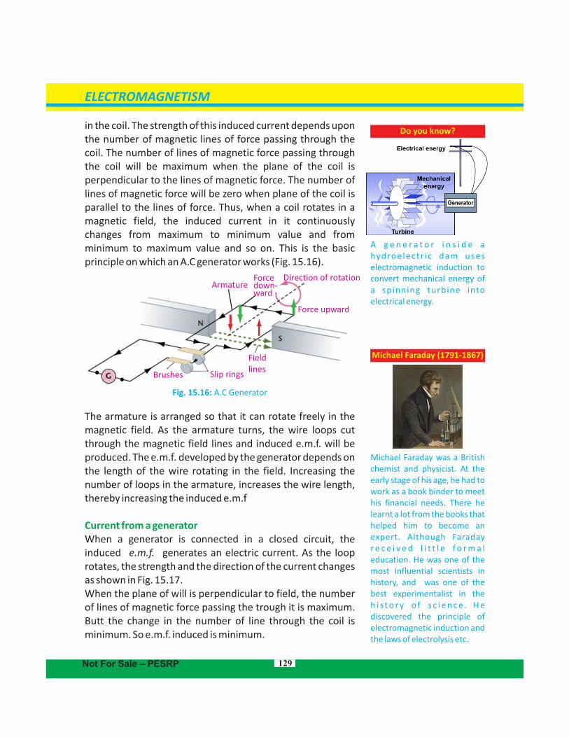
in the coil. The strength of this induced current depends upon the number of magnetic lines of force passing through the coil. The number of lines of magnetic force passing through the coil will be maximum when the plane of the coil is perpendicular to the lines of magnetic force. The number of lines of magnetic force will be zero when plane of the coil is parallel to the lines of force. Thus, when a coil rotates in a magnetic field, the induced current in it continuously changes from maximum to minimum value and from minimum to maximum value and so on. This is the basic principle on which an A.C generator works (Fig. 15.16).
Fig. 15.16: A.C Generator
The armature is arranged so that it can rotate freely in the magnetic field. As the armature turns, the wire loops cut through the magnetic field lines and induced e.m.f. will be produced. The e.m.f. developed by the generator depends on the length of the wire rotating in the field. Increasing the number of loops in the armature, increases the wire length, thereby increasing the induced e.m.f
Current from a generator When a generator is connected in a closed circuit, the induced e.m.f. generates an electric current. As the loop rotates, the strength and the direction of the current changes as shown in Fig. 15.17.When the plane of will is perpendicular to field, the number of lines of magnetic force passing the trough it is maximum. Butt the change in the number of line through the coil is minimum. So e.m.f. induced is minimum.
Connection:A generator is a d.c motor with its input and output reversed.
130
For your information
Walk-through metal detectors are installed at airports and other places for security purpose. These detectors detect metal weapons etc. u s i n g t h e p r i n c i p l e o f electromagnetic induction.
ELECTROMAGNETISM
Not For Sale – PESRP
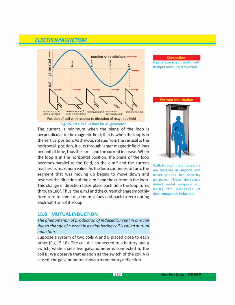
Fig. 15.17: e.m.f. Vs time for AC generator
The current is minimum when the plane of the loop is perpendicular to the magnetic field; that is, when the loop is in the vertical position. As the loop rotates from the vertical to the horizontal position, it cuts through larger magnetic field lines per unit of time, thus the e.m.f and the current increase. When the loop is in the horizontal position, the plane of the loop becomes parallel to the field, so the e.m.f and the current reaches its maximum value. As the loop continues to turn, the segment that was moving up begins to move down and reverses the direction of the e.m.f and the current in the loop. This change in direction takes place each time the loop turns through 180°. Thus, the e.m.f and the current change smoothly from zero to some maximum values and back to zero during each half-turn of the loop.
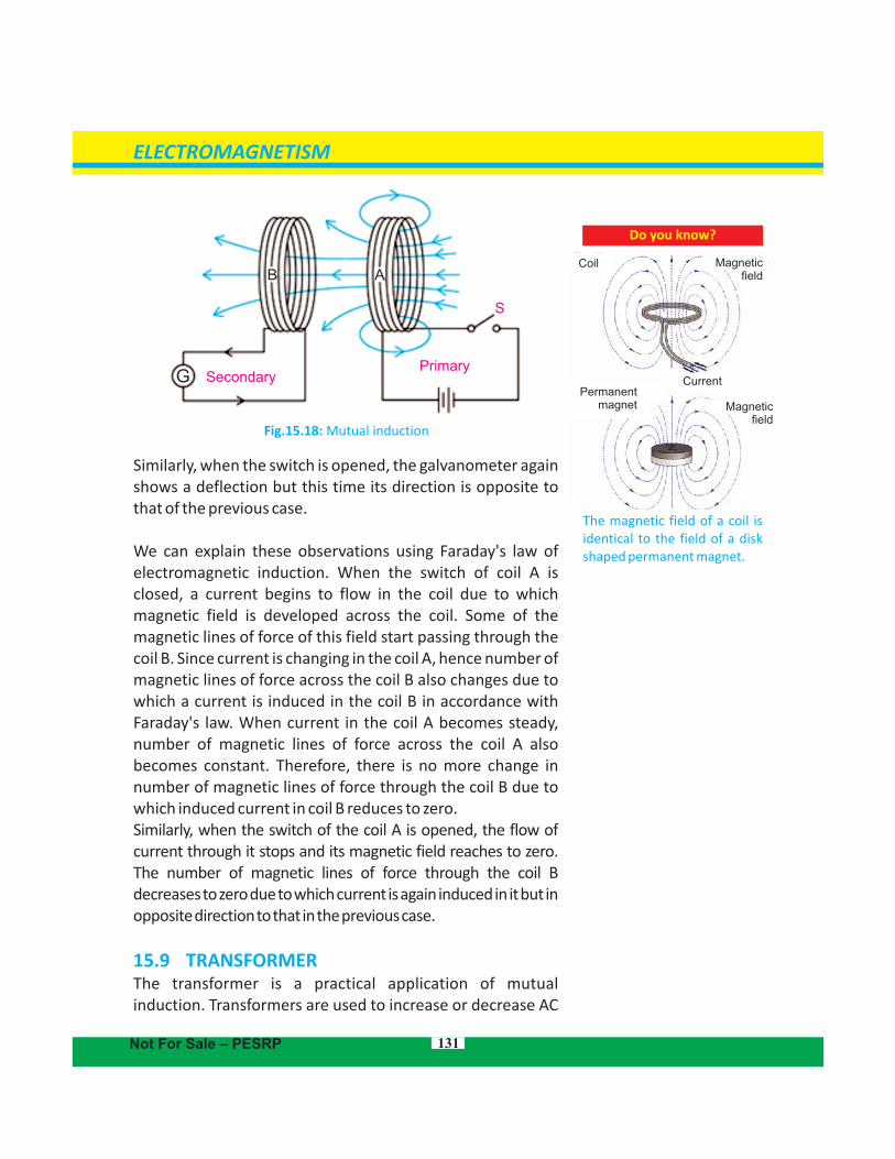
15.8 MUTUAL INDUCTIONThe phenomenon of production of induced current in one coil due to change of current in a neighboring coil is called mutual induction.Suppose a system of two coils A and B placed close to each other (Fig.15.18). The coil A is connected to a battery and a switch, while a sensitive galvanometer is connected to the coil B. We observe that as soon as the switch of the coil A is closed, the galvanometer shows a momentary deflection.
Position of coil with respect to direction of magnetic field
e.m
.f. g
ener
ated
minimum e.m.f. (coil is vertical)
maximum e.m.f(coil is horizontal)
minimum e.m.f maximum reversed e.m.f.
number of revolutions
134
12
14
minimum e.m.f
t
SecondaryPrimary
G
B A
S
Fig.15.18: Mutual induction
Similarly, when the switch is opened, the galvanometer again shows a deflection but this time its direction is opposite to that of the previous case.
We can explain these observations using Faraday's law of electromagnetic induction. When the switch of coil A is closed, a current begins to flow in the coil due to which magnetic field is developed across the coil. Some of the magnetic lines of force of this field start passing through the coil B. Since current is changing in the coil A, hence number of magnetic lines of force across the coil B also changes due to which a current is induced in the coil B in accordance with Faraday's law. When current in the coil A becomes steady, number of magnetic lines of force across the coil A also becomes constant. Therefore, there is no more change in number of magnetic lines of force through the coil B due to which induced current in coil B reduces to zero. Similarly, when the switch of the coil A is opened, the flow of current through it stops and its magnetic field reaches to zero. The number of magnetic lines of force through the coil B decreases to zero due to which current is again induced in it but in opposite direction to that in the previous case.
15.9 TRANSFORMERThe transformer is a practical application of mutual induction. Transformers are used to increase or decrease AC
131
Do you know?
The magnetic field of a coil is identical to the field of a disk shaped permanent magnet.
Coil Magnetic field
Current
Magnetic field
Permanentmagnet
ELECTROMAGNETISM
Not For Sale – PESRP
voltages. Usage of transformers is common because they change voltages with relatively little loss of energy. In fact, many of the devices in our homes, such as game systems, printers, and stereos use transformers for their working.
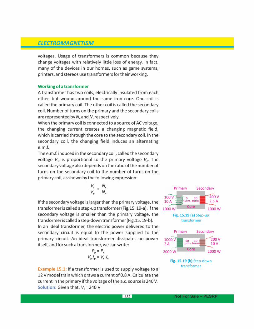
Working of a transformer A transformer has two coils, electrically insulated from each other, but wound around the same iron core. One coil is called the primary coil. The other coil is called the secondary coil. Number of turns on the primary and the secondary coils are represented by N and N respectively.P S
When the primary coil is connected to a source of AC voltage, the changing current creates a changing magnetic field, which is carried through the core to the secondary coil. In the secondary coil, the changing field induces an alternating e.m.f. The e.m.f. induced in the secondary coil, called the secondary voltage V , is proportional to the primary voltage V . The S P
secondary voltage also depends on the ratio of the number of turns on the secondary coil to the number of turns on the primary coil, as shown by the following expression:
If the secondary voltage is larger than the primary voltage, the transformer is called a step-up transformer (Fig.15. 19-a). If the secondary voltage is smaller than the primary voltage, the transformer is called a step-down transformer (Fig.15. 19-b).In an ideal transformer, the electric power delivered to the secondary circuit is equal to the power supplied to the primary circuit. An ideal transformer dissipates no power itself, and for such a transformer, we can write:
P = Pp s
V = Vp p s sI I
Example 15.1: If a transformer is used to supply voltage to a 12 V model train which draws a current of 0.8 A. Calculate the current in the primary if the voltage of the a.c. source is 240 V.Solution: Given that, V = 240 Vp
132
Fig. 15.19 (a) Step-up transformer
Fig. 15.19 (b) Step-down transformer
Primary Secondary
400 V2.5 A
100 V10 A
1000 W1000 WCore
20 turns
5turns
Primary Secondary
1000 V2 A
200 V10 A
2000 W2000 WCore
50 turns
10turns
ELECTROMAGNETISM
Not For Sale – PESRP
Vs
Vp
Ns
Np
=
Is sVVp
(12 V) (0.8 A)240 V
I =p or Ip = = 0.04 A
V = 12 Vs
= 0.8 AsI I = ?p
By law of conservation of energy, Input power of the primary = Output power of the secondary I V = Vp s i.e., Ip s
Therefore,
15.10 HIGH VOLTAGE TRANSMISSIONElectric power is usually generated at places which are far from the places where it is consumed. The power is transmitted over
long distances at high voltage to minimize the loss of energy in the form of heat during transmission. As heat dissipated in the
2transmission cable of resistance R is I Rt. Hence, by reducing the current through the cable, power loss in the form of heat dissipation can also be reduced. So the alternating voltage is stepped up at the generating station. It is then transmitted to the main sub-station. This voltage is stepped down and is transmitted to the switching transformer station or the city sub-station. At the city sub-station, it is further stepped down to 220 V and supplied to the consumers. A schematic diagram of high voltage transmission is shown in Fig. 15.20.
Fig.15.20: High voltage transmission
Transformers play an essential part in power distribution. Transformers work only with A.C. This is one reason why
133
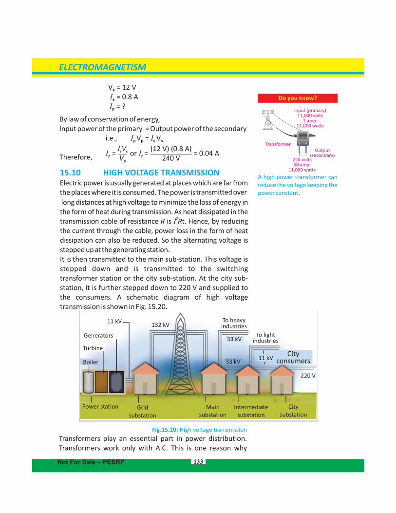
Do you know?
A high power transformer can reduce the voltage keeping the power constant.
Input (primary)11,000 volts
1 amp.11,000 watts
220 volts50 amp.
11,000 watts
Output (secondary)
Transformer
ELECTROMAGNETISM
Not For Sale – PESRP
11 kV
Generators
Turbine
Boiler
Power station Grid substation
Main substation
City substation
Intermediate substation
132 kV
33 kV
To heavyindustries
To lightindustries
Cityconsumers33 kV
11 kV
220 V
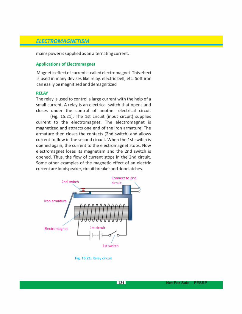
mains power is supplied as an alternating current.
Applications of Electromagnet
Magnetic effect of current is called electromagnet. This effect is used in many devises like relay, electric bell, etc. Soft iron can easily be magnitized and demagnitized
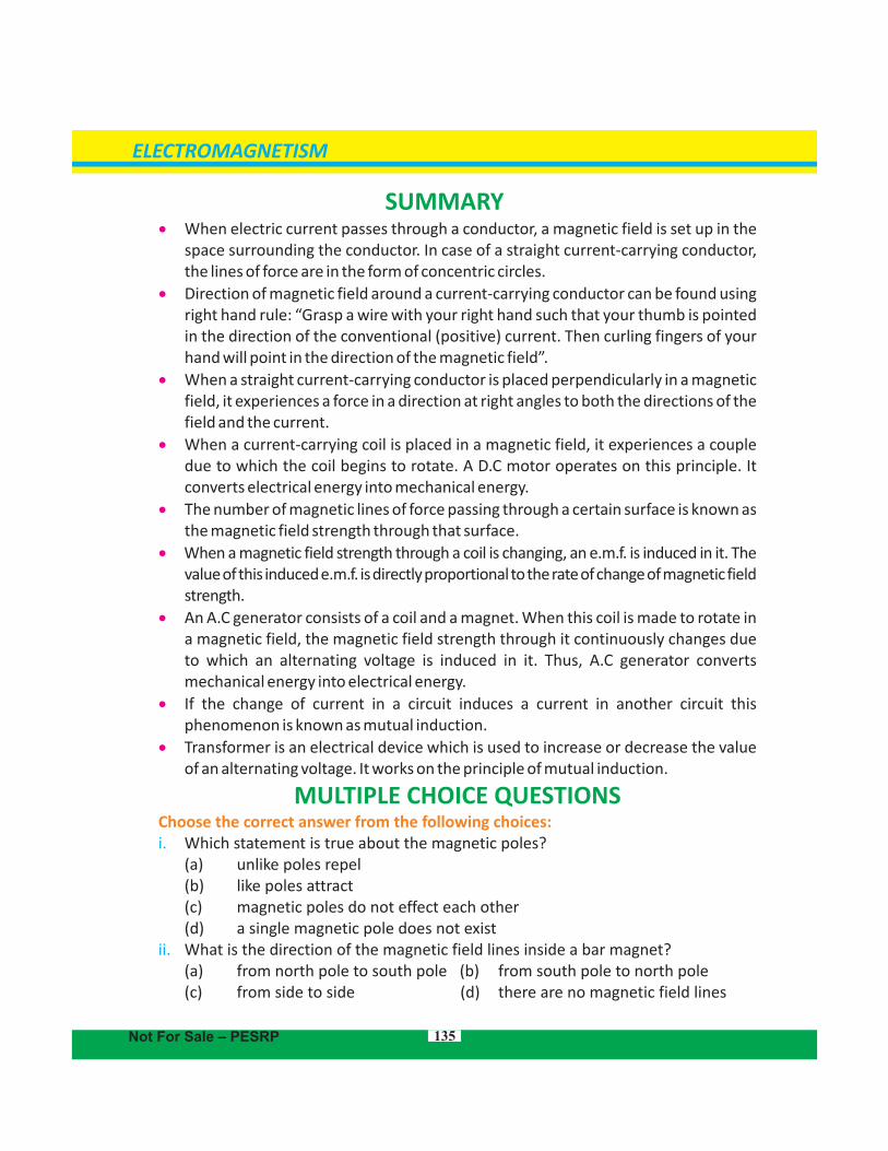
RELAYThe relay is used to control a large current with the help of a small current. A relay is an electrical switch that opens and closes under the control of another electrical circuit (Fig. 15.21). The 1st circuit (input circuit) supplies current to the electromagnet. The electromagnet is magnetized and attracts one end of the iron armature. The armature then closes the contacts (2nd switch) and allows current to flow in the second circuit. When the 1st switch is opened again, the current to the electromagnet stops. Now electromagnet loses its magnetism and the 2nd switch is opened. Thus, the flow of current stops in the 2nd circuit. Some other examples of the magnetic effect of an electric current are loudspeaker, circuit breaker and door latches.
Fig. 15.21: Relay circuit
2nd switchConnect to 2ndcircuit
Iron armature
Electromagnet
1st switch
1st circuit
ELECTROMAGNETISM
Not For Sale – PESRP134
135
SUMMARY When electric current passes through a conductor, a magnetic field is set up in the
space surrounding the conductor. In case of a straight current-carrying conductor, the lines of force are in the form of concentric circles.
Direction of magnetic field around a current-carrying conductor can be found using right hand rule: “Grasp a wire with your right hand such that your thumb is pointed in the direction of the conventional (positive) current. Then curling fingers of your hand will point in the direction of the magnetic field”.
When a straight current-carrying conductor is placed perpendicularly in a magnetic field, it experiences a force in a direction at right angles to both the directions of the field and the current.
When a current-carrying coil is placed in a magnetic field, it experiences a couple due to which the coil begins to rotate. A D.C motor operates on this principle. It converts electrical energy into mechanical energy.
The number of magnetic lines of force passing through a certain surface is known as the magnetic field strength through that surface.
When a magnetic through a coil is changing, an e.m.f. is induced in it. The field strength value of this induced e.m.f. is directly proportional to the rate of change of magnetic field strength.
An A.C generator consists of a coil and a magnet. When this coil is made to rotate in a magnetic field, the magnetic through it continuously changes due field strengthto which an alternating voltage is induced in it. Thus, A.C generator converts mechanical energy into electrical energy.
If the change of current in a circuit induces a current in another circuit this phenomenon is known as mutual induction.
Transformer is an electrical device which is used to increase or decrease the value of an alternating voltage. It works on the principle of mutual induction.
MULTIPLE CHOICE QUESTIONSChoose the correct answer from the following choices:i. Which statement is true about the magnetic poles?
(a) unlike poles repel (b) like poles attract (c) magnetic poles do not effect each other (d) a single magnetic pole does not exist
ii. What is the direction of the magnetic field lines inside a bar magnet?(a) from north pole to south pole (b) from south pole to north pole( (c) from side to side d) there are no magnetic field lines
ELECTROMAGNETISM
Not For Sale – PESRP
136
iii. The presence of a magnetic field can be detected by a( (a) small mass b) stationary positive charge(c) ( stationary negative charge d) magnetic compass
iv. If the current in a wire which is placed perpendicular to a magnetic field increases, the force on the wire(a) increases b) decreases ((c) remains the same d) will be zero(
v. A D.C motor converts(a) mechanical energy into electrical energy(b) mechanical energy into chemical energy(c) electrical energy into mechanical energy (d) electrical energy into chemical energy
vi. Which part of a D.C motor reverses the direction of current through the coil every half-cycle?(a) the armature b) the commutator(( (c) the brushes d) the slip rings
vii. The direction of induced e.m.f. in a circuit is in accordance with conservation of ( (a) mass b) charge ( (d) momentum d) energy
viii. The step-up transformer (a) increases the input current (b) increases the input voltage (c) has more turns in the primary (d) has less turns in the secondary coil
ix. The turn ratios of a transformer is10. It means ( I (a) I = 10 b) N = N /10s p s p
(c) ( N = 10 N d) V = V /10s p s p
REVIEW QUESTIONS
15.1. Demonstrate by an experiment that a magnetic field is produced around a straight current-carrying conductor.15.2. State and explain the rule by which the direction of the lines of force of the magnetic field around a current-carrying conductor can be determined.15.3. You are given an unmarked magnetized steel bar and bar magnet, its north and south ends are marked N and S respectively. State how would you determine the p o l a r i t y at each end of the unmarked bar? 15.4. When a straight current-carrying conductor is placed in a magnetic field, it experiences a force. State the rule by which the direction of this force can be found out.
ELECTROMAGNETISM
Not For Sale – PESRP
137
15.5. State that a current-carrying coil in a magnetic field experiences a torque.15.6. What is an electric motor? Explain the working principle of D.C motor.15.7. Describe a simple experiment to demonstrate that a changing magnetic field can induce e.m.f. in a circuit.15.8. What are the factors which affect the magnitude of the e.m.f. induced in a circuit by a changing magnetic field? 15.9. Describe the direction of an induced e.m.f. in a circuit? How does this phenomenon relate to conservation of energy? 15.10. Draw a labelled diagram to illustrate the structure and working of A.C generator. 15.11. What do you understand by the term mutual induction? 15.12. What is a transformer? Explain the working of a transformer in connection with mutual induction. 15.13. The voltage chosen for the transmission of electrical power over large distances is many times greater than the voltage of the domestic supply. State two reasons why electrical power is transmitted at high voltage.15.14. Why is the voltage used for the domestic supply much lower than the voltage at which the power is transmitted?
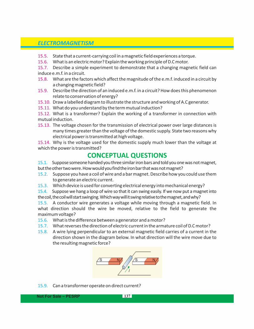
CONCEPTUAL QUESTIONS15.1. Suppose someone handed you three similar iron bars and told you one was not magnet, but the other two were. How would you find the iron bar that was not magnet?15.2. Suppose you have a coil of wire and a bar magnet. Describe how you could use them to generate an electric current.15.3. Which device is used for converting electrical energy into mechanical energy?15.4. Suppose we hang a loop of wire so that it can swing easily. If we now put a magnet into the coil, the coil will start swinging. Which way will it swing relative to the magnet, and why?15.5. A conductor wire generates a voltage while moving through a magnetic field. In what direction should the wire be moved, relative to the field to generate the maximum voltage?15.6. What is the difference between a generator and a motor? 15.7. What reverses the direction of electric current in the armature coil of D.C motor? 15.8. A wire lying perpendicular to an external magnetic field carries of a current in the direction shown in the diagram below. In what direction will the wire move due to the resulting magnetic force?
15.9. Can a transformer operate on direct current?
ELECTROMAGNETISM
SS NN
I
Not For Sale – PESRP
138
NUMERICAL PROBLEMS15.1. A transformer is needed to convert a mains 240 V supply into a 12 V supply. If there are 2000 turns on the primary coil, then find the number of turns on the secondary coil. Ans. (100)15.2. A step-up transformer has a turn ratios of 1 : 100. An alternating supply of 20 V is connected across the primary coil. What is the secondary voltage? Ans. (2000 V)15.3. A step-down transformer has a turns ratio of 100 : 1. An ac voltage of amplitude 170 V is applied to the primary. If the current in the primary is 1.0 mA, what is the current in the secondary? Ans. (0.1A)15.4. A transformer, designed to convert the voltage from 240 V a.c mains to 12 V, has 4000 turns on the primary coil. How many turns should be on the secondary coil? If the transformer were 100% efficient, what current would flow through the primary coil when the current in the secondary coil was 0.4 A? Ans. (200, 0.02A)15.5. A power station generates 500 MW of electrical power which is fed to a transmission line. What current would flow in the transmission line, if the input voltage is 250 kV? 3Ans. (2 x 10 A)
ELECTROMAGNETISM
Not For Sale – PESRP