Embed Size (px)
Citation preview
1
Unit 14 – Timers and Counters
2
A BRIEF SUMMARY Review of some key concepts from the first half of the semester
3
A Few Big Ideas 1
• Setting and clearing bits in a register tells the hardware what do and when (this is SW interacting with HW)
• Speed matters – Your software is executing quickly compared to how fast a human can
do something
– You can use that to your advantage: blinking an LED at a fast rate can give the illusion it's always on but just more dim
– Or it can work to your disadvantage: One button press may look like many because a loop may see one press on multiple iterations.
– We must write our software with this in mind
4
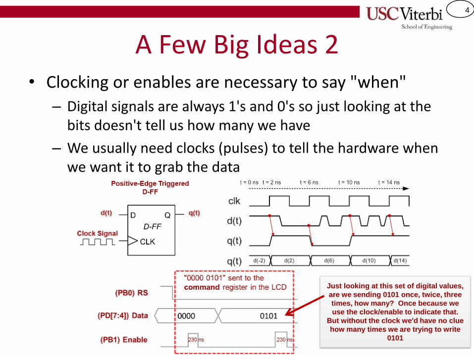
A Few Big Ideas 2 • Clocking or enables are necessary to say "when"
– Digital signals are always 1's and 0's so just looking at the bits doesn't tell us how many we have
– We usually need clocks (pulses) to tell the hardware when we want it to grab the data
Just looking at this set of digital values,
are we sending 0101 once, twice, three
times, how many? Once because we
use the clock/enable to indicate that.
But without the clock we'd have no clue
how many times we are trying to write
0101
5
A Few Big Ideas 3
• External events happen asynchronously with your software (don't know "when" something has happened)
– Your software program is the brains for how to process information but it doesn't magically know "when" something has happened?
– We have to keep checking it (polling) or
– Hardware designers built "interrupt" mechanisms to help
• Many tasks can be done in either SW or HW; SW may be easier to code/use but HW provides parallelism
– A 0.1 second timer can be done in SW using delays but then software can't do much else
– Or in HW using timers allowing SW to do other tasks
6
TIMERS
7
Counter/Timers Overview
• ATmega328P has two 8-bit and one 16-bit counters.
– Can configure to count at some frequency up to some value (a.k.a. counter modulus), generate an interrupt and start over counting again, if desired
– Useful for performing operations at specific time intervals. Every time an interrupt occurs, do something.
– Can be used for other tasks such as pulse-width modulation (covered in future lectures)
• But don't we already have delay()…why do we need timers
– So that we can do other useful work while we are waiting for time to elapse!
8
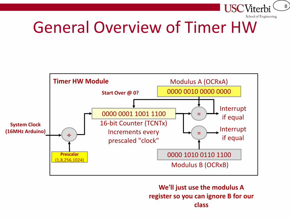
General Overview of Timer HW
0000 0001 1001 1100
16-bit Counter (TCNTx) Increments every prescaled "clock"
=
0000 0010 0000 0000
Modulus A (OCRxA)
=
0000 1010 0110 1100
Modulus B (OCRxB)
Interrupt if equal
Interrupt if equal
Start Over @ 0?
System Clock (16MHz Arduino)
Prescalar (1,8,256,1024)
Timer HW Module
We'll just use the modulus A register so you can ignore B for our
class
9
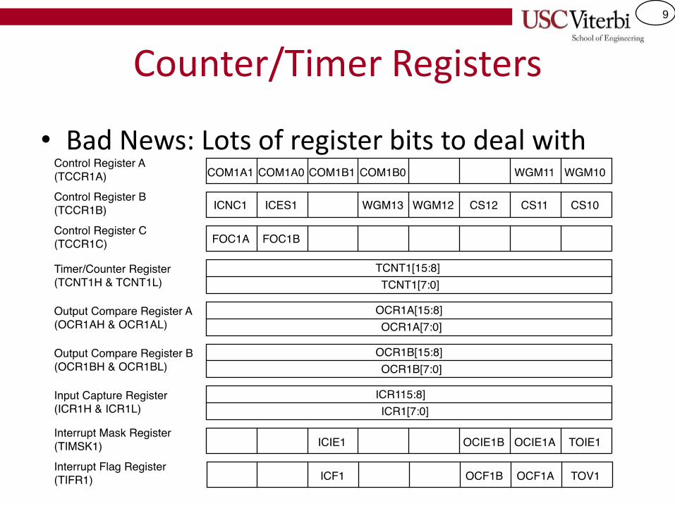
Counter/Timer Registers
• Bad News: Lots of register bits to deal with
10
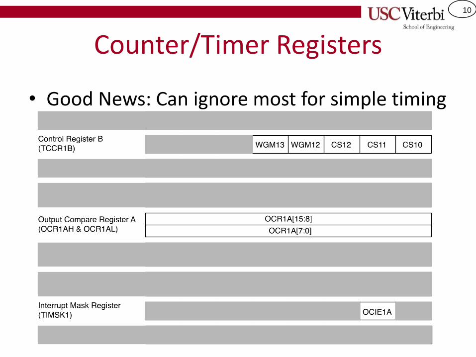
Counter/Timer Registers
• Good News: Can ignore most for simple timing
11
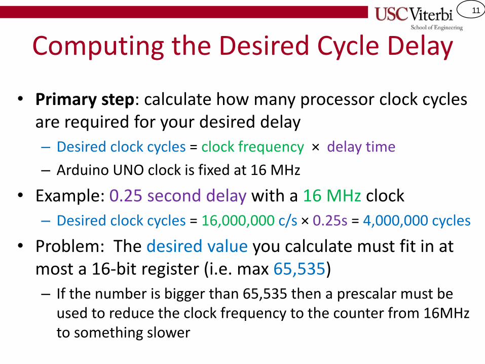
Computing the Desired Cycle Delay
• Primary step: calculate how many processor clock cycles are required for your desired delay
– Desired clock cycles = clock frequency × delay time
– Arduino UNO clock is fixed at 16 MHz
• Example: 0.25 second delay with a 16 MHz clock
– Desired clock cycles = 16,000,000 c/s × 0.25s = 4,000,000 cycles
• Problem: The desired value you calculate must fit in at most a 16-bit register (i.e. max 65,535)
– If the number is bigger than 65,535 then a prescalar must be used to reduce the clock frequency to the counter from 16MHz to something slower
12
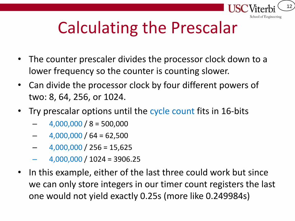
Calculating the Prescalar
• The counter prescaler divides the processor clock down to a lower frequency so the counter is counting slower.
• Can divide the processor clock by four different powers of two: 8, 64, 256, or 1024.
• Try prescalar options until the cycle count fits in 16-bits – 4,000,000 / 8 = 500,000
– 4,000,000 / 64 = 62,500
– 4,000,000 / 256 = 15,625
– 4,000,000 / 1024 = 3906.25
• In this example, either of the last three could work but since we can only store integers in our timer count registers the last one would not yield exactly 0.25s (more like 0.249984s)
13
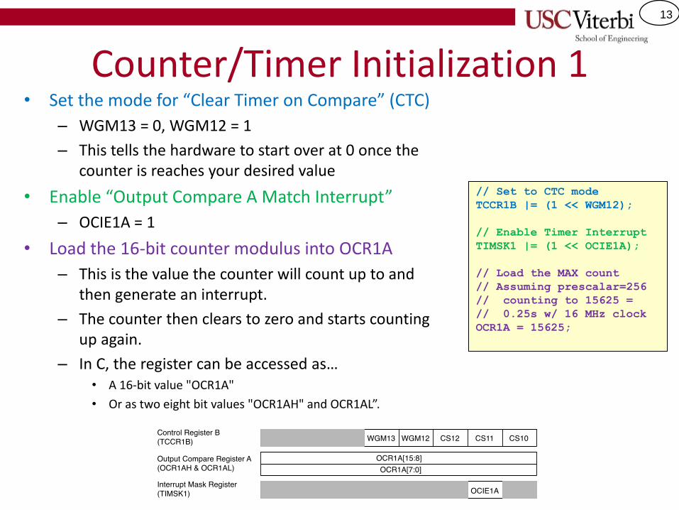
Counter/Timer Initialization 1 • Set the mode for “Clear Timer on Compare” (CTC)
– WGM13 = 0, WGM12 = 1
– This tells the hardware to start over at 0 once the counter is reaches your desired value
• Enable “Output Compare A Match Interrupt”
– OCIE1A = 1
• Load the 16-bit counter modulus into OCR1A
– This is the value the counter will count up to and then generate an interrupt.
– The counter then clears to zero and starts counting up again.
– In C, the register can be accessed as… • A 16-bit value "OCR1A"
• Or as two eight bit values "OCR1AH" and OCR1AL”.
// Set to CTC mode
TCCR1B |= (1 << WGM12);
// Enable Timer Interrupt
TIMSK1 |= (1 << OCIE1A);
// Load the MAX count
// Assuming prescalar=256
// counting to 15625 =
// 0.25s w/ 16 MHz clock
OCR1A = 15625;
14
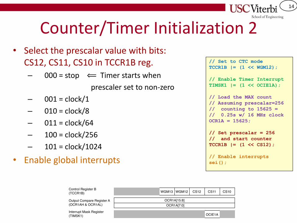
Counter/Timer Initialization 2 • Select the prescalar value with bits:
CS12, CS11, CS10 in TCCR1B reg. – 000 = stop ⟸ Timer starts when
prescaler set to non-zero
– 001 = clock/1
– 010 = clock/8
– 011 = clock/64
– 100 = clock/256
– 101 = clock/1024
• Enable global interrupts
// Set to CTC mode
TCCR1B |= (1 << WGM12);
// Enable Timer Interrupt
TIMSK1 |= (1 << OCIE1A);
// Load the MAX count
// Assuming prescalar=256
// counting to 15625 =
// 0.25s w/ 16 MHz clock
OCR1A = 15625;
// Set prescalar = 256
// and start counter
TCCR1B |= (1 << CS12);
// Enable interrupts
sei();
15
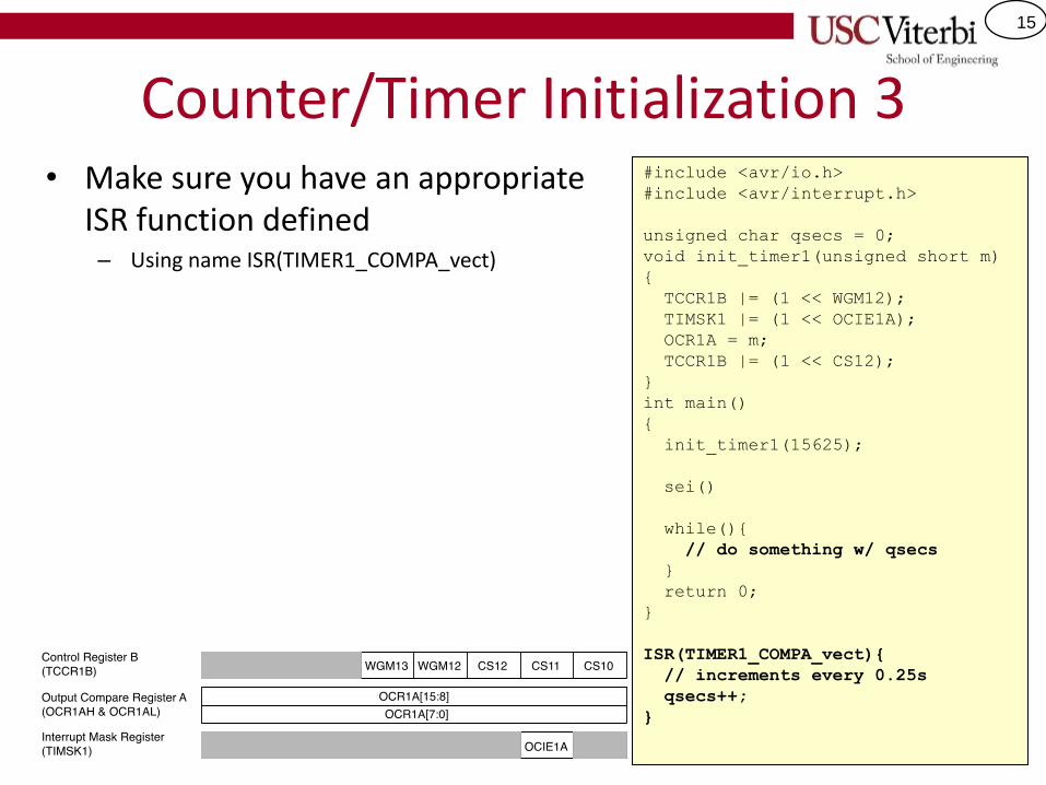
Counter/Timer Initialization 3 • Make sure you have an appropriate
ISR function defined – Using name ISR(TIMER1_COMPA_vect)
#include <avr/io.h>
#include <avr/interrupt.h>
unsigned char qsecs = 0;
void init_timer1(unsigned short m)
{
TCCR1B |= (1 << WGM12);
TIMSK1 |= (1 << OCIE1A);
OCR1A = m;
TCCR1B |= (1 << CS12);
}
int main()
{
init_timer1(15625);
sei()
while(){
// do something w/ qsecs
}
return 0;
}
ISR(TIMER1_COMPA_vect){
// increments every 0.25s
qsecs++;
}
16
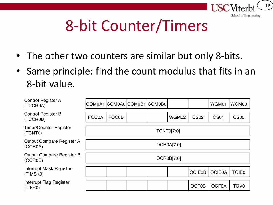
8-bit Counter/Timers
• The other two counters are similar but only 8-bits.
• Same principle: find the count modulus that fits in an 8-bit value.
17
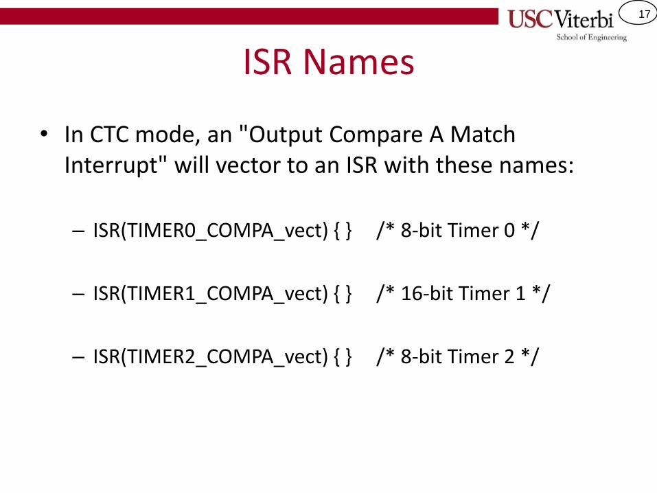
ISR Names
• In CTC mode, an "Output Compare A Match Interrupt" will vector to an ISR with these names:
– ISR(TIMER0_COMPA_vect) { } /* 8-bit Timer 0 */
– ISR(TIMER1_COMPA_vect) { } /* 16-bit Timer 1 */
– ISR(TIMER2_COMPA_vect) { } /* 8-bit Timer 2 */