Embed Size (px)
Citation preview
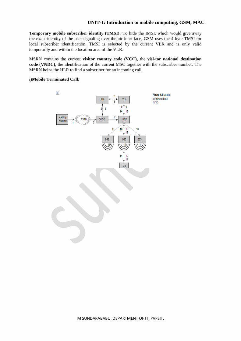
UNIT-1: Introduction to mobile computing, GSM, MAC.
M SUNDARABABU, DEPARTMENT OF IT, PVPSIT.
UNIT-1
Introduction to Mobile Computing
• The process of computation on a mobile-device.
• In mobile computing, a set of distributed computing systems or service provider servers
participate, connect, and synchronise through mobile communication protocols
• Provides decentralized (distributed) computations on diversified devices, systems, and
networks, which are mobile, synchronized, and interconnected via mobile communication
standards and protocols.
• Mobile device does not restrict itself to just one application, such as, voice communication
• Offers mobility with computing power
• Facilitates a large number of applications on a single device
• Also called pervasive computing when a set of computing devices, systems, or networks have
the characteristics of transparency, application-aware adaptation, and have an environment
sensing ability
Novel applications:
SmartPhone Feature Example.
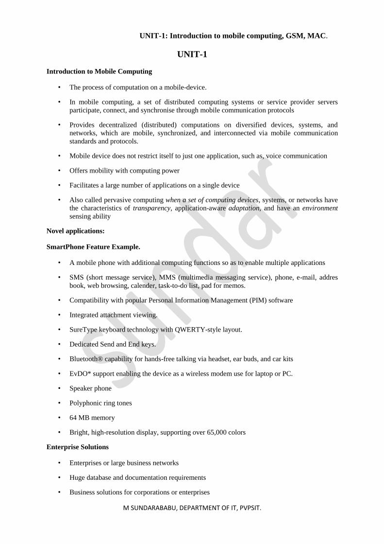
• A mobile phone with additional computing functions so as to enable multiple applications
• SMS (short message service), MMS (multimedia messaging service), phone, e-mail, addres
book, web browsing, calender, task-to-do list, pad for memos.
• Compatibility with popular Personal Information Management (PIM) software
• Integrated attachment viewing.
• SureType keyboard technology with QWERTY-style layout.
• Dedicated Send and End keys.
• Bluetooth® capability for hands-free talking via headset, ear buds, and car kits
• EvDO* support enabling the device as a wireless modem use for laptop or PC.
• Speaker phone
• Polyphonic ring tones
• 64 MB memory
• Bright, high-resolution display, supporting over 65,000 colors
Enterprise Solutions
• Enterprises or large business networks
• Huge database and documentation requirements
• Business solutions for corporations or enterprises
UNIT-1: Introduction to mobile computing, GSM, MAC.
M SUNDARABABU, DEPARTMENT OF IT, PVPSIT.
Mobile Computing application to Music and Video
• Example─ Apple iPods enables listening to one’s favourite tunes anytime and anywhere
• View photo albums
• Slide shows
• Video clips
Mobile Commerce
• Stock quotes in real time or on demand.
• The stock purchases or selling
• Bank transactions
• Retail purchases
• Supply chain management
• e-Ticketing─ booking cinema, train, flight, and bus tickets
Limitations to mobile computing
• Resource constraints: Battery
• Interference: the quality of service (QoS)
• Bandwidth: connection latency
• Dynamic changes in communication environment: variations in signal power within a region,
thus link delays and connection losses
• Network Issues: discovery of the connection-service to destination and connection stability
• Interoperability issues: the varying protocol standards
• Security constraints: Protocols conserving privacy of communication
UNIT-1: Introduction to mobile computing, GSM, MAC.
M SUNDARABABU, DEPARTMENT OF IT, PVPSIT.
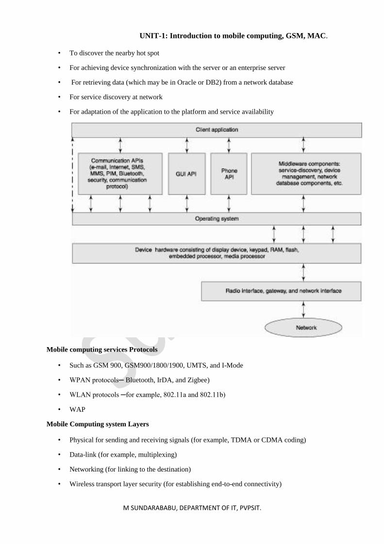
Mobile Computing Architecture
• Programming languages used for mobile system software
• Operating system functions to run the software components onto the hardware
• Middleware components deployment
• Layered structure arrangement of mobile computing components
• Protocols and layers used for transmission and reception
Programming Languages
• Java J2SE.
• J2ME (Java2 Micro edition)
• JavaCard (Java for smart card)
• The Java enterprise edition (J2EE) used for web and enterprise server based applications of
mobile services
• C and C++ ,Visual C++ ,Visual Basic.
Operating System
• Symbian OS, Window CE, Mac OS…
• Offers the user to run an application without considering the hardware specifications and
functionalities
• Provides functions which are used for scheduling the multiple tasks in a system
• Provides the functions required for the synchronization of multiple tasks in the system
• Multiple threads synchronization and priority allocation
• Management functions (such as creation, activation, deletion, suspension, and delay) for tasks
and memory .
• Provides Interfaces for communication between software components at the application layer,
middleware layers, and hardware devices
• Facilitates execution of software components on diversified hardware.
• Provides Configurable libraries for the GUI (graphic user interface) in the device.
• Provides User application’s GUIs, VUI (voice user interface) components, and phone API
• Provides the device drivers for the keyboard, display, USB, and other devices
Middleware for Mobile Systems
• Software components that link the application components with the network-distributed
components
• To discover the nearby device such as Bluetooth
UNIT-1: Introduction to mobile computing, GSM, MAC.
M SUNDARABABU, DEPARTMENT OF IT, PVPSIT.
• To discover the nearby hot spot
• For achieving device synchronization with the server or an enterprise server
• For retrieving data (which may be in Oracle or DB2) from a network database
• For service discovery at network
• For adaptation of the application to the platform and service availability
Mobile computing services Protocols
• Such as GSM 900, GSM900/1800/1900, UMTS, and I-Mode
• WPAN protocols─ Bluetooth, IrDA, and Zigbee)
• WLAN protocols ─for example, 802.11a and 802.11b)
• WAP
Mobile Computing system Layers
• Physical for sending and receiving signals (for example, TDMA or CDMA coding)
• Data-link (for example, multiplexing)
• Networking (for linking to the destination)
• Wireless transport layer security (for establishing end-to-end connectivity)
UNIT-1: Introduction to mobile computing, GSM, MAC.
M SUNDARABABU, DEPARTMENT OF IT, PVPSIT.
• Wireless transaction protocol
• Wireless session protocol
• Wireless application environment (for running a web application, for example, mobile e-
business)
GSM (global system for mobile communications):
GSM is the most successful digital mobile telecommunication system in the world today. It is used by
over 800 million people in more than 190 countries. In the early 1980s, Europe had numerous
coexisting analog mobile phone sys-tems, which were often based on similar standards (e.g., NMT
450), but ran on slightly different carrier frequencies. To avoid this situation for a second genera-tion
fully digital system, the groupe spéciale mobile (GSM) was founded in 1982. This system was soon
named the global system for mobile communications (GSM), with the specification process lying in
the hands of ETSI (ETSI, 2002), (GSM Association, 2002).
GSM is a typical second generation system, replacing the first generation analogy systems, but not
offering the high worldwide data rates that the third generation systems, such as UMTS, are
promising. GSM has initially been deployed in Europe using 890–915 MHz for uplinks and 935–960
MHz for downlinks – this system is now also called GSM 900 to distinguish it from the later versions.
These versions comprise GSM at 1800 MHz (1710–1785 MHz uplink, 1805–1880 MHz downlink),
also called DCS (digital cellular system) 1800.
The following section describes the architecture, services, and protocols of GSM that are common to
all three major solutions, GSM 900, GSM 1800, and GSM 1900.
Mobile services:
GSM permits the integration of different voice and data services and the inter-working with existing
networks. Services make a network interesting for customers. GSM has defined three different
categories of services: bearer, tele, and supplementary services. These are described in the following
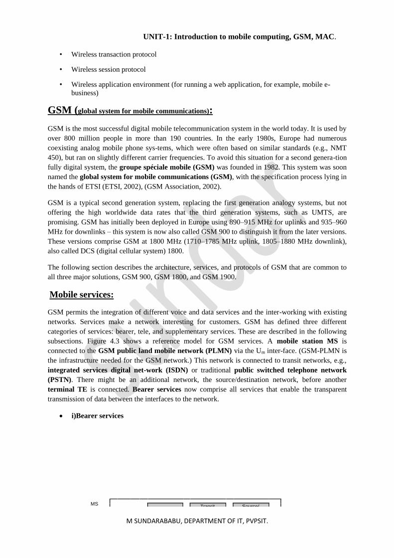
subsections. Figure 4.3 shows a reference model for GSM services. A mobile station MS is
connected to the GSM public land mobile network (PLMN) via the Um inter-face. (GSM-PLMN is
the infrastructure needed for the GSM network.) This network is connected to transit networks, e.g.,
integrated services digital net-work (ISDN) or traditional public switched telephone network
(PSTN). There might be an additional network, the source/destination network, before another
terminal TE is connected. Bearer services now comprise all services that enable the transparent
transmission of data between the interfaces to the network.
• i)Bearer services
MS
Transit Source/
UNIT-1: Introduction to mobile computing, GSM, MAC.
M SUNDARABABU, DEPARTMENT OF IT, PVPSIT.
Bearer services
permit transparent
and non-
transparent, synchronous or asynchronous data transmission. Transparent bearer services only use
the functions of the physi-cal layer to transmit data. Data transmission has a constant delay and
throughput if no transmission errors occur. The only mechanism to increase.
Figure 4.3 Bearer and tele services reference model
transmission quality is the use of forward error correction (FEC), which codes redundancy into the
data stream and helps to reconstruct the original data in case of transmission errors.. Non-transparent
bearer services use protocols of layers two and three to implement error correction and flow control.
These services use the transparent bearer services, adding a radio link protocol (RLP). This protocol
comprises mechanisms of high-level data link control (HDLC).
• ii)Tele services
GSM mainly focuses on voice-oriented tele services. These comprise encrypted voice transmission,
message services, and basic data communication with termi-nals as known from the PSTN or
ISDN.Another service offered by GSM is the emergency number. This service is mandatory for all
providers and free of charge. This connection also has the highest priority, possibly pre-empting other
connections. A useful service for very simple message transfer is the short message ser-vice (SMS),
which offers transmission of messages of up to 160 characters. The successor of SMS, the enhanced
message service (EMS), offers a larger message size (e.g., 760 characters, concatenating several
SMs), formatted text. EMS never really took off as the multimedia message service (MMS) was
avail-able..
• iii)Supplementary services
Services are user identification, call redirection, or forwarding of ongoing calls. Standard ISDN
features such as closed user groups and multi-party communication may be available.
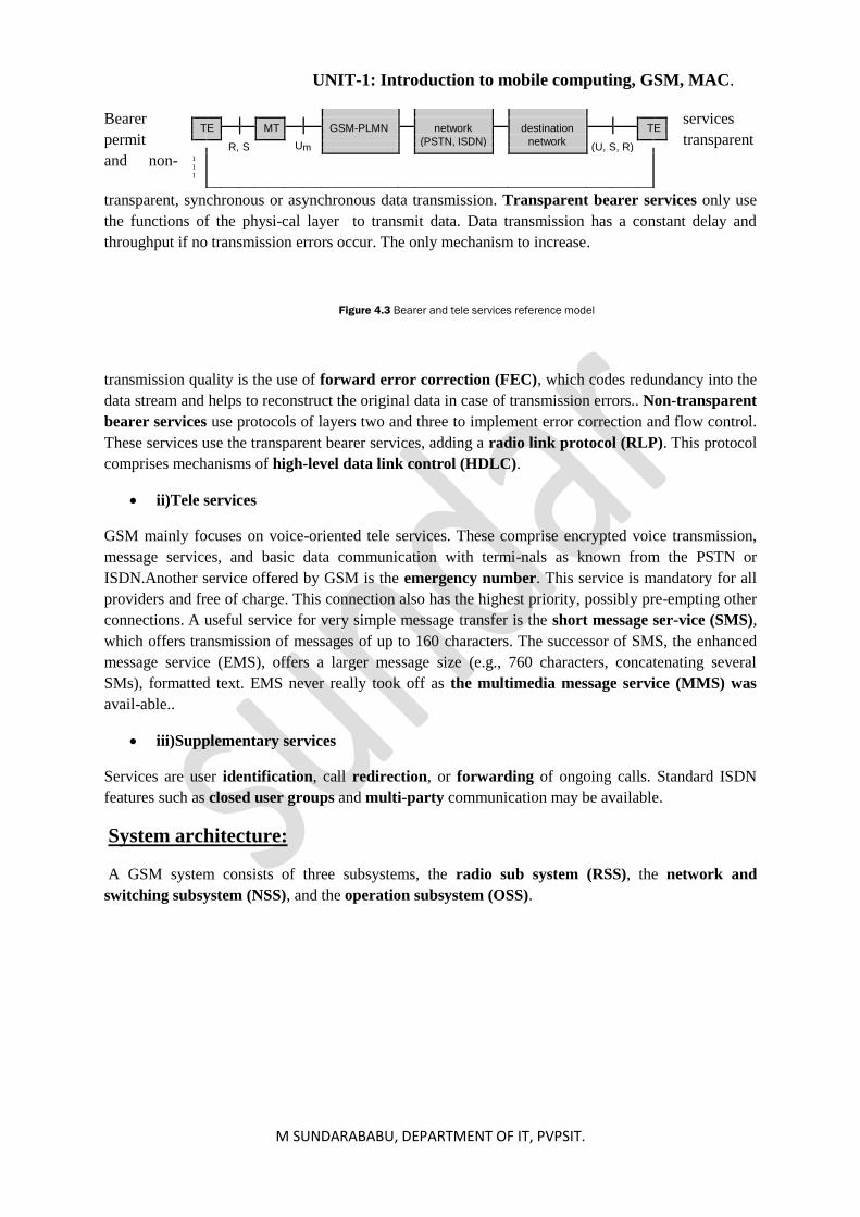
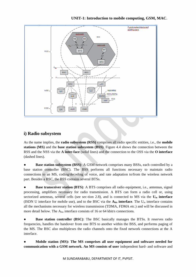
System architecture:
A GSM system consists of three subsystems, the radio sub system (RSS), the network and
switching subsystem (NSS), and the operation subsystem (OSS).
TE
MT
GSM-PLMN
network
destination
TE
R, S
Um
(PSTN, ISDN)
network (U, S, R)
1
1
1
UNIT-1: Introduction to mobile computing, GSM, MAC.
M SUNDARABABU, DEPARTMENT OF IT, PVPSIT.
i) Radio subsystem
As the name implies, the radio subsystem (RSS) comprises all radio specific entities, i.e., the mobile
stations (MS) and the base station subsystem (BSS). Figure 4.4 shows the connection between the
RSS and the NSS via the A inter-face (solid lines) and the connection to the OSS via the O interface
(dashed lines).
● Base station subsystem (BSS): A GSM network comprises many BSSs, each controlled by a
base station controller (BSC). The BSS performs all functions necessary to maintain radio
connections to an MS, coding/decoding of voice, and rate adaptation to/from the wireless network
part. Besides a BSC, the BSS contains several BTSs.
● Base transceiver station (BTS): A BTS comprises all radio equipment, i.e., antennas, signal
processing, amplifiers necessary for radio transmission. A BTS can form a radio cell or, using
sectorized antennas, several cells (see sec-tion 2.8), and is connected to MS via the Um interface
(ISDN U interface for mobile use), and to the BSC via the Abis interface. The Um interface contains
all the mechanisms necessary for wireless transmission (TDMA, FDMA etc.) and will be discussed in
more detail below. The Abis interface consists of 16 or 64 kbit/s connections.
● Base station controller (BSC): The BSC basically manages the BTSs. It reserves radio
frequencies, handles the handover from one BTS to another within the BSS, and performs paging of
the MS. The BSC also multiplexes the radio channels onto the fixed network connections at the A
interface.
● Mobile station (MS): The MS comprises all user equipment and software needed for
communication with a GSM network. An MS consists of user independent hard- and software and
UNIT-1: Introduction to mobile computing, GSM, MAC.
M SUNDARABABU, DEPARTMENT OF IT, PVPSIT.
of the subscriber identity module (SIM), which stores all user-specific data that is relevant to GSM.3
While an MS can be identified via the international mobile equipment identity (IMEI), a user can
personalize any MS using his or her SIM. Without the SIM, only emergency calls are possible. The
SIM card contains many identifiers and tables, such as card-type, serial number, a list of subscribed
services, a personal identity number (PIN), a PIN unblocking key (PUK), an authentication key
Ki, and the inter-national mobile subscriber identity (IMSI) (ETSI, 1991c). The PIN is used to
unlock the MS. Using the wrong PIN three times will lock the SIM. In such cases, the PUK is needed
to unlock the SIM.
ii) Network and switching subsystem
The “heart” of the GSM system is formed by the network and switching sub-system (NSS). The
NSS connects the wireless network with standard public networks, performs handovers between
different BSSs, comprises functions for worldwide localization of users and supports charging,
accounting, and roaming of users between different providers in different countries. The NSS consists
of the following switches and database
● Mobile services switching center (MSC): MSCs are high-performance digi-tal ISDN
switches. They set up connections to other MSCs and to the BSCs via the A interface, and form the
fixed backbone network of a GSM system. Typically, an MSC manages several BSCs in a
geographical region. A gateway MSC (GMSC) has additional connections to other fixed networks,
such as PSTN and ISDN. Using additional interworking functions (IWF), an MSC
Home location register (HLR): The HLR is the most important database in a GSM system as it
stores all user-relevant information. This comprises static information, such as the mobile subscriber
ISDN number (MSISDN), sub-scribed services (e.g., call forwarding, roaming restrictions, GPRS),
and the international mobile subscriber identity (IMSI). Dynamic information is also needed, e.g.,
the current location area (LA) of the MS, the mobile sub-scriber roaming number (MSRN), the
current VLR and MSC. As soon as an MS leaves its current LA, the information in the HLR is
updated.
Visitor location register (VLR): The VLR associated to each MSC is a dynamic database which
stores all important information needed for the MS users currently in the LA that is associated to the
MSC. ). If a new MS comes into an LA the VLR is respons-ible for, it copies all relevant information
for this user from the HLR.
iii) Operation subsystem
The third part of a GSM system, the operation subsystem (OSS), contains the necessary functions
for network operation and maintenance.
Operation and maintenance center (OMC): The OMC monitors and con-trols all other network
entities via the O interface (SS7 with X.25). Typical OMC management functions are traffic
monitoring, status reports of net-work entities, subscriber and security management, or accounting
and billing.
Authentication centre (AuC): As the radio interface and mobile stations are particularly vulnerable,
a separate AuC has been defined to protect user identity and data transmission. The AuC contains the
algorithms for authentication as well as the keys for encryption and generates the values needed for
user authentication in the HLR
UNIT-1: Introduction to mobile computing, GSM, MAC.
M SUNDARABABU, DEPARTMENT OF IT, PVPSIT.
Equipment identity register (EIR): The EIR is a database for all IMEIs, i.e., it stores all device
identifications registered for this network. As MSs are mobile, they can be easily stolen.the EIR also
contains a list of valid IMEIs (white list), and a list of malfunctioning devices (gray list).
Radio interface:
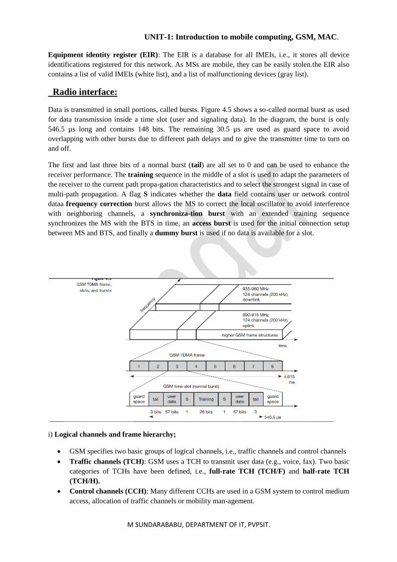
Data is transmitted in small portions, called bursts. Figure 4.5 shows a so-called normal burst as used
for data transmission inside a time slot (user and signaling data). In the diagram, the burst is only
546.5 µs long and contains 148 bits. The remaining 30.5 µs are used as guard space to avoid
overlapping with other bursts due to different path delays and to give the transmitter time to turn on
and off.
The first and last three bits of a normal burst (tail) are all set to 0 and can be used to enhance the
receiver performance. The training sequence in the middle of a slot is used to adapt the parameters of
the receiver to the current path propa-gation characteristics and to select the strongest signal in case of
multi-path propagation. A flag S indicates whether the data field contains user or network control
dataa frequency correction burst allows the MS to correct the local oscillator to avoid interference
with neighboring channels, a synchroniza-tion burst with an extended training sequence
synchronizes the MS with the BTS in time, an access burst is used for the initial connection setup
between MS and BTS, and finally a dummy burst is used if no data is available for a slot.
i) Logical channels and frame hierarchy;
• GSM specifies two basic groups of logical channels, i.e., traffic channels and control channels
• Traffic channels (TCH): GSM uses a TCH to transmit user data (e.g., voice, fax). Two basic
categories of TCHs have been defined, i.e., full-rate TCH (TCH/F) and half-rate TCH
(TCH/H).
• Control channels (CCH): Many different CCHs are used in a GSM system to control medium
access, allocation of traffic channels or mobility man-agement.
UNIT-1: Introduction to mobile computing, GSM, MAC.
M SUNDARABABU, DEPARTMENT OF IT, PVPSIT.
▪ Broadcast control channel (BCCH): A BTS uses this channel to signal information to
all MSs within a cell. Information transmitted in this channel, e.g., the cell identifier.
▪ The BTS sends information for frequency correction via the frequency correction
channel (FCCH) and information about time synchronization via the synchronization
channel (SCH), where both channels are subchannels of the BCCH.
▪ Common control channel (CCCH):
▪ All information regarding connec-tion setup between MS and BS is exchanged via the
CCCH. For calls toward an MS, the BTS uses the paging channel (PCH) for paging the
appropriate MS. If an MS wants to set up a call, it uses the random access channel
(RACH) to send data to the BTS. The RACH implements multiple access (all MSs within
a cell may access this channel) using slot-ted Aloha. The BTS uses the access grant
channel (AGCH) to signal an MS that it can use a TCH or SDCCH for further
connection setup.
▪ Dedicated control channel (DCCH):
▪ following channels are bidirectional. As long as an MS has not established a TCH with
the BTS, it uses the stand-alone dedicated control channel (SDCCH) with a low data
rate (782 bit/s) for signalling.
▪ This can comprise authentication, registration or other data needed for setting up a TCH.
Each TCH and SDCCH has a slow associated dedicated control channel (SACCH)
associated with it.
▪ GSM uses a fast asso-ciated dedicated control channel (FACCH). The FACCH uses
the time slots which are otherwise used by the TCH.
Protocols:
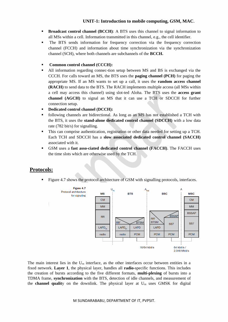
▪ Figure 4.7 shows the protocol architecture of GSM with signalling protocols, interfaces.
The main interest lies in the Um interface, as the other interfaces occur between entities in a
fixed network. Layer 1, the physical layer, handles all radio-specific functions. This includes
the creation of bursts according to the five different formats, multi-plexing of bursts into a
TDMA frame, synchronization with the BTS, detection of idle channels, and measurement of
the channel quality on the downlink. The physical layer at Um uses GMSK for digital
UNIT-1: Introduction to mobile computing, GSM, MAC.
M SUNDARABABU, DEPARTMENT OF IT, PVPSIT.
modulation and performs encryption/decryption of data, i.e., encryption is not performed end-
to-end, but only between MS and BSS over the air interface.
Synchronization also includes the correction of the individual path delay between an MS and the
BTS. All MSs within a cell use the same BTS and thus must be synchronized to this BTS. The
BTS generates the time-structure of frames, slots.
LAPDm protocol has been defined at the Um interface for layer two. LAPDm, as the name
already implies, has been derived from link access procedure for the D-channel (LAPD) in
ISDN systems. LAPDm offers reliable data transfer over connections, re-sequencing of data
frames, and flow control (ETSI, 1993b), (ETSI, 1993c).. defined for the Um interface. Further
services provided by LAPDm include segmentation and reassembly of data and
acknowledged/unacknowledged data transfer.
The network layer in GSM, layer three, comprises several sublayers as Figure 4.7 shows. The
lowest sublayer is the radio resource management (RR). Only a part of this layer, RR’, is
implemented in the BTS, the remainder is situ-ated in the BSC. The functions of RR’ are
supported by the BSC via the BTS management (BTSM). The main tasks of RR are setup,
maintenance, and release of radio channels. RR also directly accesses the physical layer for
radio information and offers a reliable connection to the next higher layer.
Mobility management (MM) contains functions for registration, authentica-tion, identification,
location updating, and the provision of a temporary mobile subscriber identity (TMSI) that
replaces the international mobile subscriber identity (IMSI).
Finally, the call management (CM) layer contains three entities: call con-trol (CC), short
message service (SMS), and supplementary service (SS). SMS allows for message transfer
using the control channels SDCCH and SACCH.
Data transmission at the physical layer typically uses pulse code modulation (PCM) systems. .
LAPD is used for layer two at Abis, BTSM for BTS management.
Signaling system No. 7 (SS7) is used for signalling between an MSC and a BSC. This protocol
also transfers all management information between MSCs, HLR, VLRs, AuC, EIR, and OMC.
An MSC can also control a BSS via a BSS application part (BSSAP).
Localization and calling:
To locate an MS and to address the MS, several numbers are needed:
Mobile station international ISDN number (MSISDN): The only important number for a user
of GSM is the phone number. Remember that the phone number is not associated with a certain
device but with the SIM, which is personalized for a user. The MSISDN follows the ITU-T
standard E.164 for addresses as it is also used in fixed ISDN networks. This number consists of
the country code (CC) (e.g., +49 179 1234567 with 49 for Germany), the national destination
code (NDC) (i.e., the address of the network provider, e.g., 179), and the subscriber number
(SN).
International mobile subscriber identity (IMSI): GSM uses the IMSI for internal unique
identification of a subscriber. IMSI consists of a mobile country code (MCC) (e.g., 240 for
Sweden, 208 for France), the mobile network code (MNC) (i.e., the code of the network
provider), and finally the mobile subscriber identification number (MSIN).
UNIT-1: Introduction to mobile computing, GSM, MAC.
M SUNDARABABU, DEPARTMENT OF IT, PVPSIT.
Temporary mobile subscriber identity (TMSI): To hide the IMSI, which would give away
the exact identity of the user signaling over the air inter-face, GSM uses the 4 byte TMSI for
local subscriber identification. TMSI is selected by the current VLR and is only valid
temporarily and within the location area of the VLR.
MSRN contains the current visitor country code (VCC), the visi-tor national destination
code (VNDC), the identification of the current MSC together with the subscriber number. The
MSRN helps the HLR to find a subscriber for an incoming call.
i)Mobile Terminated Call:
UNIT-1: Introduction to mobile computing, GSM, MAC.
M SUNDARABABU, DEPARTMENT OF IT, PVPSIT.
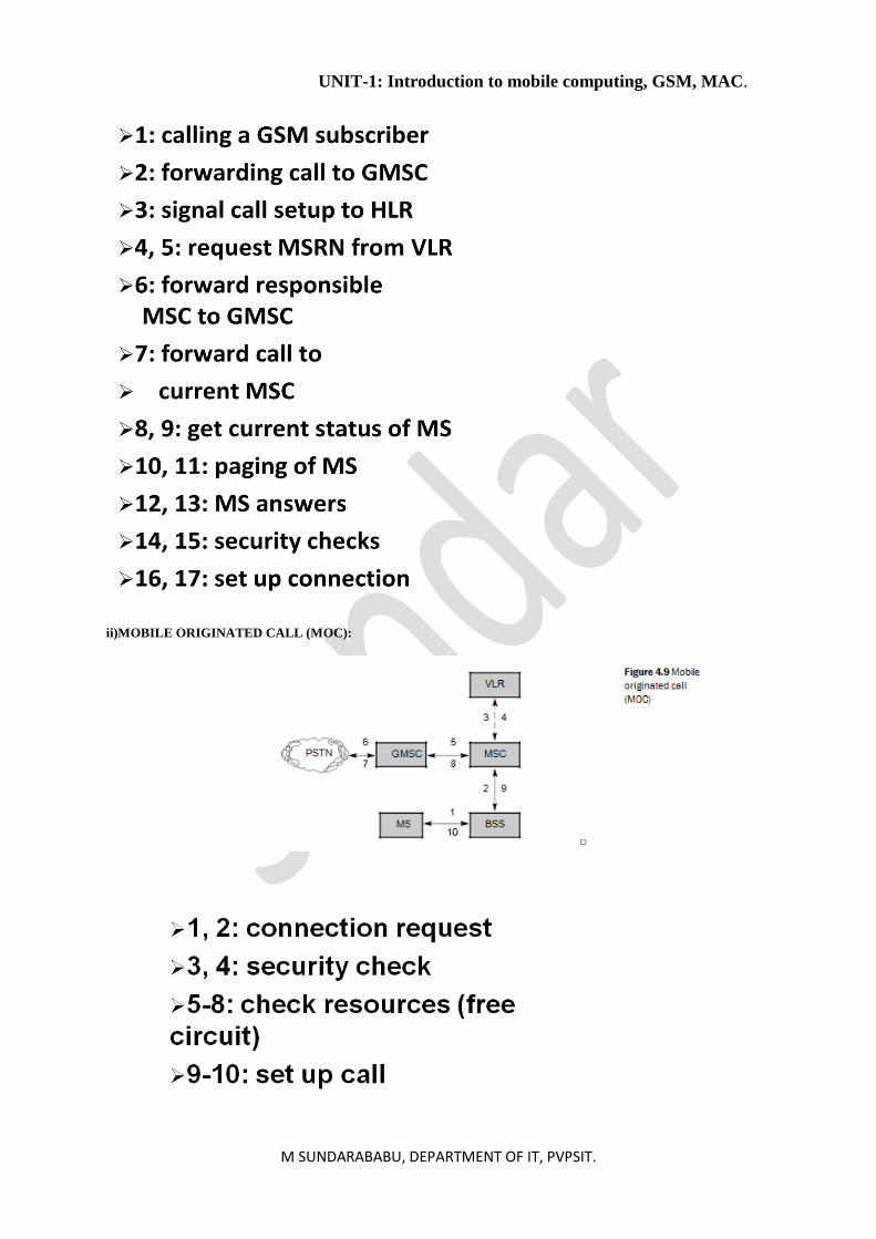
ii)MOBILE ORIGINATED CALL (MOC):
UNIT-1: Introduction to mobile computing, GSM, MAC.
M SUNDARABABU, DEPARTMENT OF IT, PVPSIT.
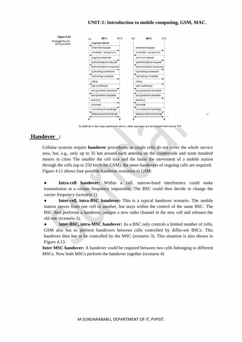
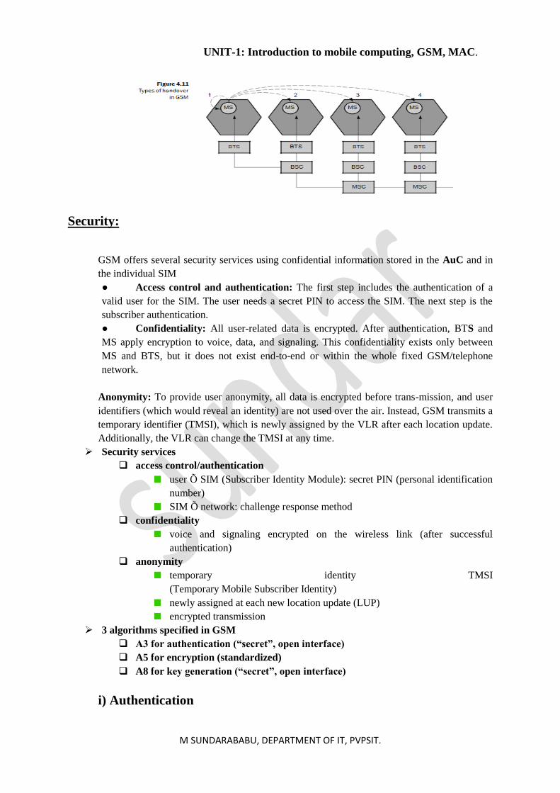
Handover :
Cellular systems require handover procedures, as single cells do not cover the whole service
area, but, e.g., only up to 35 km around each antenna on the countryside and some hundred
meters in cities The smaller the cell size and the faster the movement of a mobile station
through the cells (up to 250 km/h for GSM), the more handovers of ongoing calls are required.
Figure 4.11 shows four possible handover scenarios in GSM:
● Intra-cell handover: Within a cell, narrow-band interference could make
transmission at a certain frequency impossible. The BSC could then decide to change the
carrier frequency (scenario 1).
● Inter-cell, intra-BSC handover: This is a typical handover scenario. The mobile
station moves from one cell to another, but stays within the control of the same BSC. The
BSC then performs a handover, assigns a new radio channel in the new cell and releases the
old one (scenario 2).
● Inter-BSC, intra-MSC handover: As a BSC only controls a limited number of cells;
GSM also has to perform handovers between cells controlled by differ-ent BSCs. This
handover then has to be controlled by the MSC (scenario 3). This situation is also shown in
Figure 4.13.
Inter MSC handover: A handover could be required between two cells belonging to different
MSCs. Now both MSCs perform the handover together (scenario 4)
UNIT-1: Introduction to mobile computing, GSM, MAC.
M SUNDARABABU, DEPARTMENT OF IT, PVPSIT.
Security:
GSM offers several security services using confidential information stored in the AuC and in
the individual SIM
● Access control and authentication: The first step includes the authentication of a
valid user for the SIM. The user needs a secret PIN to access the SIM. The next step is the
subscriber authentication.
● Confidentiality: All user-related data is encrypted. After authentication, BTS and
MS apply encryption to voice, data, and signaling. This confidentiality exists only between
MS and BTS, but it does not exist end-to-end or within the whole fixed GSM/telephone
network.
Anonymity: To provide user anonymity, all data is encrypted before trans-mission, and user
identifiers (which would reveal an identity) are not used over the air. Instead, GSM transmits a
temporary identifier (TMSI), which is newly assigned by the VLR after each location update.
Additionally, the VLR can change the TMSI at any time.
➢ Security services
access control/authentication
user Õ SIM (Subscriber Identity Module): secret PIN (personal identification
number)
SIM Õ network: challenge response method
confidentiality
voice and signaling encrypted on the wireless link (after successful
authentication)
anonymity
temporary identity TMSI
(Temporary Mobile Subscriber Identity)
newly assigned at each new location update (LUP)
encrypted transmission
➢ 3 algorithms specified in GSM
A3 for authentication (“secret”, open interface)
A5 for encryption (standardized)
A8 for key generation (“secret”, open interface)
i) Authentication
UNIT-1: Introduction to mobile computing, GSM, MAC.
M SUNDARABABU, DEPARTMENT OF IT, PVPSIT.
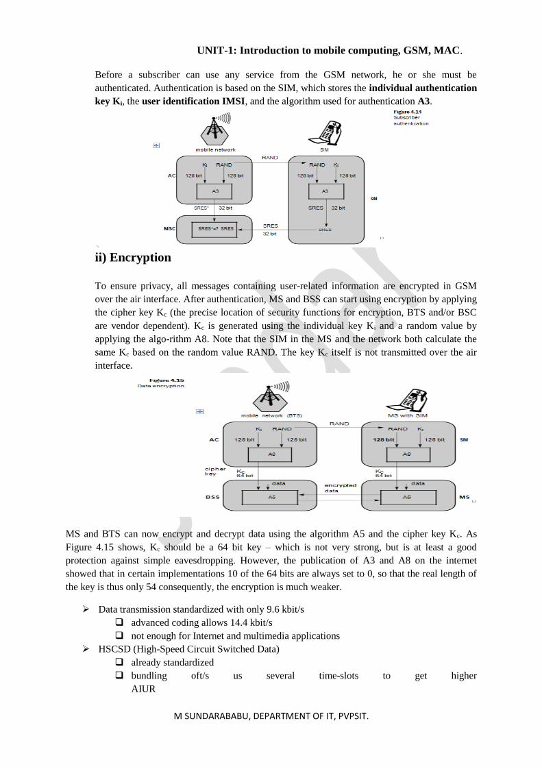
Before a subscriber can use any service from the GSM network, he or she must be
authenticated. Authentication is based on the SIM, which stores the individual authentication
key Ki, the user identification IMSI, and the algorithm used for authentication A3.
ii) Encryption
To ensure privacy, all messages containing user-related information are encrypted in GSM
over the air interface. After authentication, MS and BSS can start using encryption by applying
the cipher key Kc (the precise location of security functions for encryption, BTS and/or BSC
are vendor dependent). Kc is generated using the individual key Ki and a random value by
applying the algo-rithm A8. Note that the SIM in the MS and the network both calculate the
same Kc based on the random value RAND. The key Kc itself is not transmitted over the air
interface.
MS and BTS can now encrypt and decrypt data using the algorithm A5 and the cipher key Kc. As
Figure 4.15 shows, Kc should be a 64 bit key – which is not very strong, but is at least a good
protection against simple eavesdropping. However, the publication of A3 and A8 on the internet
showed that in certain implementations 10 of the 64 bits are always set to 0, so that the real length of
the key is thus only 54 consequently, the encryption is much weaker.
➢ Data transmission standardized with only 9.6 kbit/s
advanced coding allows 14.4 kbit/s
not enough for Internet and multimedia applications
➢ HSCSD (High-Speed Circuit Switched Data)
already standardized
bundling oft/s us several time-slots to get higher
AIUR
UNIT-1: Introduction to mobile computing, GSM, MAC.
M SUNDARABABU, DEPARTMENT OF IT, PVPSIT.
advantage: ready to use, constant quality, simple
disadvantage: channels blocked for voice transmission
➢ GPRS (General Packet Radio Service)
packet switching
using free slots only if data packets ready to send
standardization 1998
advantage: one step towards UMTS, more flexible
disadvantage: more investment needed
GPRS network elements
GSN (GPRS Support Nodes): GGSN and SGSN
GGSN (Gateway GSN)
interworking unit between GPRS and PDN (Packet Data Network)
SGSN (Serving GSN)
supports the MS (location, billing, security)
GR (GPRS Register)
user addresses
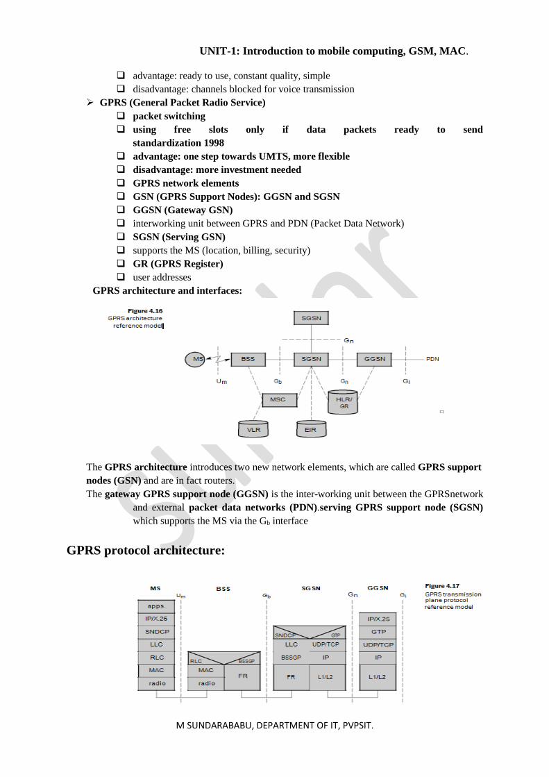
GPRS architecture and interfaces:
The GPRS architecture introduces two new network elements, which are called GPRS support
nodes (GSN) and are in fact routers.
The gateway GPRS support node (GGSN) is the inter-working unit between the GPRSnetwork
and external packet data networks (PDN).serving GPRS support node (SGSN)
which supports the MS via the Gb interface
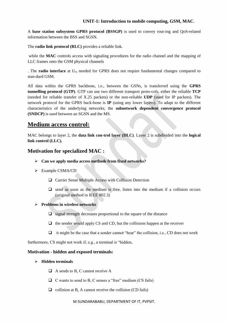
GPRS protocol architecture:
UNIT-1: Introduction to mobile computing, GSM, MAC.
M SUNDARABABU, DEPARTMENT OF IT, PVPSIT.
A base station subsystem GPRS protocol (BSSGP) is used to convey rout-ing and QoS-related
information between the BSS and SGSN.
The radio link protocol (RLC) provides a reliable link.
while the MAC controls access with signaling procedures for the radio channel and the mapping of
LLC frames onto the GSM physical channels
. The radio interface at Um needed for GPRS does not require fundamental changes compared to
stan-dard GSM.
All data within the GPRS backbone, i.e., between the GSNs, is transferred using the GPRS
tunnelling protocol (GTP). GTP can use two different transport proto-cols, either the reliable TCP
(needed for reliable transfer of X.25 packets) or the non-reliable UDP (used for IP packets). The
network protocol for the GPRS back-bone is IP (using any lower layers). To adapt to the different
characteristics of the underlying networks, the subnetwork dependent convergence protocol
(SNDCP) is used between an SGSN and the MS.
Medium access control:
MAC belongs to layer 2, the data link con-trol layer (DLC). Layer 2 is subdivided into the logical
link control (LLC).
Motivation for specialized MAC :
➢ Can we apply media access methods from fixed networks?
➢ Example CSMA/CD
Carrier Sense Multiple Access with Collision Detection
send as soon as the medium is free, listen into the medium if a collision occurs
(original method in IEEE 802.3)
➢ Problems in wireless networks
signal strength decreases proportional to the square of the distance
the sender would apply CS and CD, but the collisions happen at the receiver
it might be the case that a sender cannot “hear” the collision, i.e., CD does not work
furthermore, CS might not work if, e.g., a terminal is “hidden.
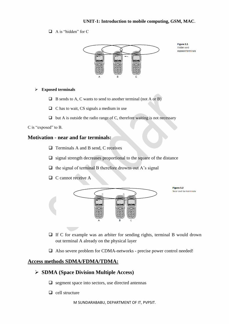
Motivation - hidden and exposed terminals:
➢ Hidden terminals
A sends to B, C cannot receive A
C wants to send to B, C senses a “free” medium (CS fails)
collision at B, A cannot receive the collision (CD fails)
UNIT-1: Introduction to mobile computing, GSM, MAC.
M SUNDARABABU, DEPARTMENT OF IT, PVPSIT.
A is “hidden” for C
➢ Exposed terminals
B sends to A, C wants to send to another terminal (not A or B)
C has to wait, CS signals a medium in use
but A is outside the radio range of C, therefore waiting is not necessary
C is “exposed” to B.
Motivation - near and far terminals:
Terminals A and B send, C receives
signal strength decreases proportional to the square of the distance
the signal of terminal B therefore drowns out A’s signal
C cannot receive A
If C for example was an arbiter for sending rights, terminal B would drown
out terminal A already on the physical layer
Also severe problem for CDMA-networks - precise power control needed!
Access methods SDMA/FDMA/TDMA:
➢ SDMA (Space Division Multiple Access)
segment space into sectors, use directed antennas
cell structure
UNIT-1: Introduction to mobile computing, GSM, MAC.
M SUNDARABABU, DEPARTMENT OF IT, PVPSIT.
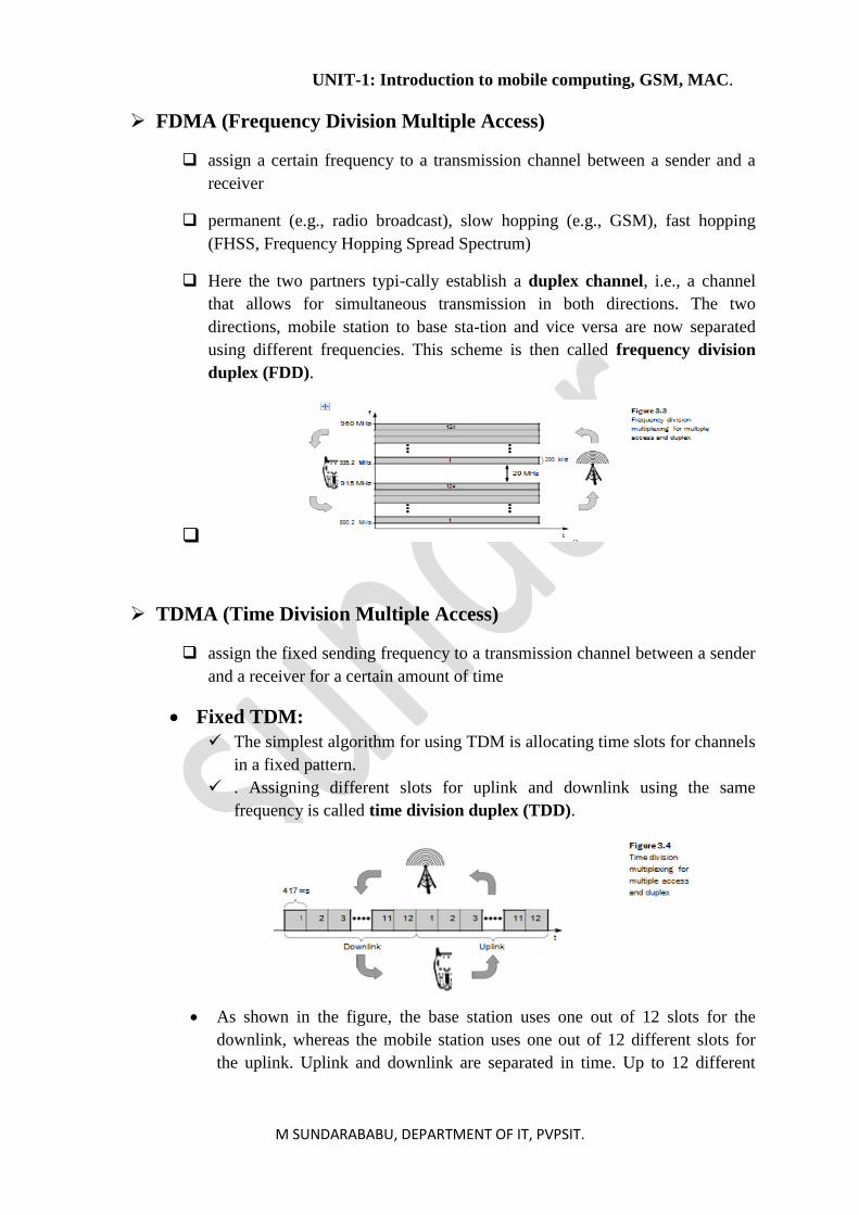
➢ FDMA (Frequency Division Multiple Access)
assign a certain frequency to a transmission channel between a sender and a
receiver
permanent (e.g., radio broadcast), slow hopping (e.g., GSM), fast hopping
(FHSS, Frequency Hopping Spread Spectrum)
Here the two partners typi-cally establish a duplex channel, i.e., a channel
that allows for simultaneous transmission in both directions. The two
directions, mobile station to base sta-tion and vice versa are now separated
using different frequencies. This scheme is then called frequency division
duplex (FDD).
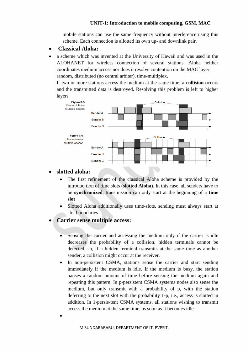
➢ TDMA (Time Division Multiple Access)
assign the fixed sending frequency to a transmission channel between a sender
and a receiver for a certain amount of time
• Fixed TDM:
✓ The simplest algorithm for using TDM is allocating time slots for channels
in a fixed pattern.
✓ . Assigning different slots for uplink and downlink using the same
frequency is called time division duplex (TDD).
• As shown in the figure, the base station uses one out of 12 slots for the
downlink, whereas the mobile station uses one out of 12 different slots for
the uplink. Uplink and downlink are separated in time. Up to 12 different
UNIT-1: Introduction to mobile computing, GSM, MAC.
M SUNDARABABU, DEPARTMENT OF IT, PVPSIT.
mobile stations can use the same frequency without interference using this
scheme. Each connection is allotted its own up- and downlink pair.
• Classical Aloha:
• a scheme which was invented at the University of Hawaii and was used in the
ALOHANET for wireless connection of several stations. Aloha neither
coordinates medium access nor does it resolve contention on the MAC layer.
random, distributed (no central arbiter), time-multiplex.
If two or more stations access the medium at the same time, a collision occurs
and the transmitted data is destroyed. Resolving this problem is left to higher
layers
• slotted aloha:
• The first refinement of the classical Aloha scheme is provided by the
introduc-tion of time slots (slotted Aloha). In this case, all senders have to
be synchronized, transmission can only start at the beginning of a time
slot
• Slotted Aloha additionally uses time-slots, sending must always start at
slot boundaries
• Carrier sense multiple access:
• Sensing the carrier and accessing the medium only if the carrier is idle
decreases the probability of a collision. hidden terminals cannot be
detected, so, if a hidden terminal transmits at the same time as another
sender, a collision might occur at the receiver.
• In non-persistent CSMA, stations sense the carrier and start sending
immediately if the medium is idle. If the medium is busy, the station
pauses a random amount of time before sensing the medium again and
repeating this pattern. In p-persistent CSMA systems nodes also sense the
medium, but only transmit with a probability of p, with the station
deferring to the next slot with the probability 1-p, i.e., access is slotted in
addition. In 1-persis-tent CSMA systems, all stations wishing to transmit
access the medium at the same time, as soon as it becomes idle.
•
UNIT-1: Introduction to mobile computing, GSM, MAC.
M SUNDARABABU, DEPARTMENT OF IT, PVPSIT.
• Demand assigned multiple access
• Channel efficiency only 18% for Aloha, 36% for Slotted Aloha (assuming
Poisson distribution for packet arrival and packet length)
• Reservation can increase efficiency to 80%
• sender reserves a future time-slot
• sending within this reserved time-slot is possible without collision
• reservation also causes higher delays
• typical scheme for satellite links
• Examples for reservation algorithms:
• Explicit Reservation according to Roberts (Reservation-ALOHA)
• Implicit Reservation (PRMA)
• Reservation-TDMA
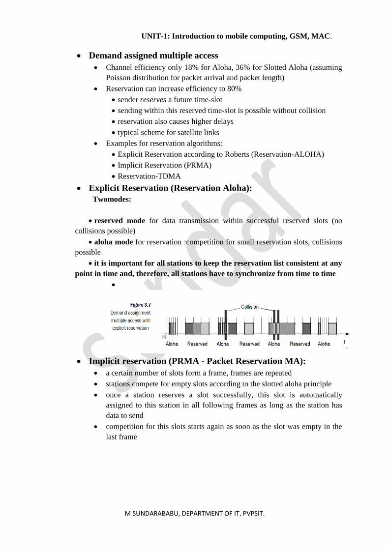
• Explicit Reservation (Reservation Aloha):
Twomodes:
• reserved mode for data transmission within successful reserved slots (no
collisions possible)
• aloha mode for reservation :competition for small reservation slots, collisions
possible
• it is important for all stations to keep the reservation list consistent at any
point in time and, therefore, all stations have to synchronize from time to time
•
• Implicit reservation (PRMA - Packet Reservation MA):
• a certain number of slots form a frame, frames are repeated
• stations compete for empty slots according to the slotted aloha principle
• once a station reserves a slot successfully, this slot is automatically
assigned to this station in all following frames as long as the station has
data to send
• competition for this slots starts again as soon as the slot was empty in the
last frame
UNIT-1: Introduction to mobile computing, GSM, MAC.
M SUNDARABABU, DEPARTMENT OF IT, PVPSIT.
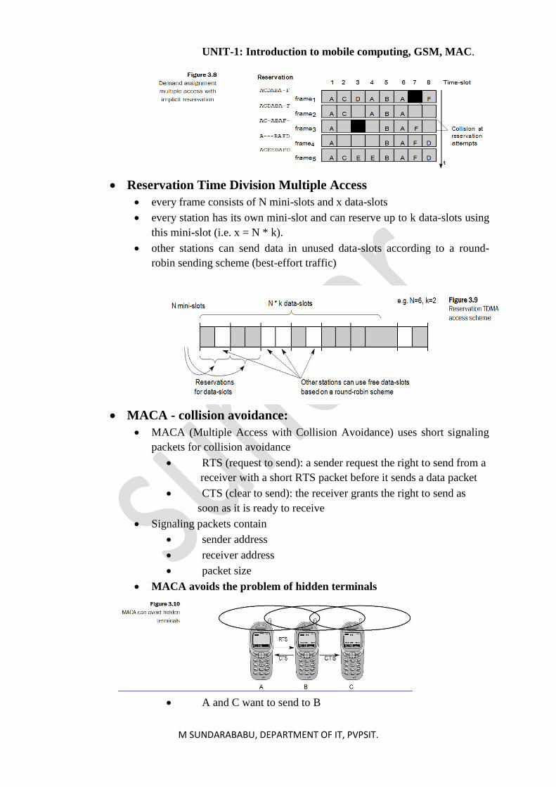
• Reservation Time Division Multiple Access
• every frame consists of N mini-slots and x data-slots
• every station has its own mini-slot and can reserve up to k data-slots using
this mini-slot (i.e. x = N * k).
• other stations can send data in unused data-slots according to a round-
robin sending scheme (best-effort traffic)
• MACA - collision avoidance:
• MACA (Multiple Access with Collision Avoidance) uses short signaling
packets for collision avoidance
• RTS (request to send): a sender request the right to send from a
receiver with a short RTS packet before it sends a data packet
• CTS (clear to send): the receiver grants the right to send as
soon as it is ready to receive
• Signaling packets contain
• sender address
• receiver address
• packet size
• MACA avoids the problem of hidden terminals
• A and C want to send to B
UNIT-1: Introduction to mobile computing, GSM, MAC.
M SUNDARABABU, DEPARTMENT OF IT, PVPSIT.
• A sends RTS first
• C waits after receiving CTS from B
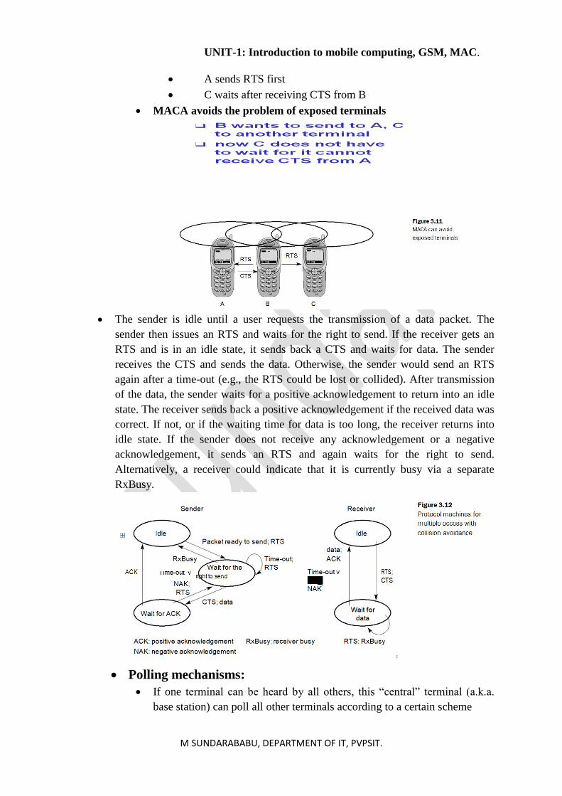
• MACA avoids the problem of exposed terminals
• The sender is idle until a user requests the transmission of a data packet. The
sender then issues an RTS and waits for the right to send. If the receiver gets an
RTS and is in an idle state, it sends back a CTS and waits for data. The sender
receives the CTS and sends the data. Otherwise, the sender would send an RTS
again after a time-out (e.g., the RTS could be lost or collided). After transmission
of the data, the sender waits for a positive acknowledgement to return into an idle
state. The receiver sends back a positive acknowledgement if the received data was
correct. If not, or if the waiting time for data is too long, the receiver returns into
idle state. If the sender does not receive any acknowledgement or a negative
acknowledgement, it sends an RTS and again waits for the right to send.
Alternatively, a receiver could indicate that it is currently busy via a separate
RxBusy.
• Polling mechanisms:
• If one terminal can be heard by all others, this “central” terminal (a.k.a.
base station) can poll all other terminals according to a certain scheme
UNIT-1: Introduction to mobile computing, GSM, MAC.
M SUNDARABABU, DEPARTMENT OF IT, PVPSIT.
• now all schemes known from fixed networks can be used (typical
mainframe - terminal scenario)
• Example: Randomly Addressed Polling
• base station signals readiness to all mobile terminals
• terminals ready to send can now transmit a random number without
collision with the help of CDMA or FDMA (the random number can be
seen as dynamic address)
• the base station now chooses one address for polling from the list of all
random numbers (collision if two terminals choose the same address)
• the base station acknowledges correct packets and continues polling the
next terminal
• this cycle starts again after polling all terminals of the list
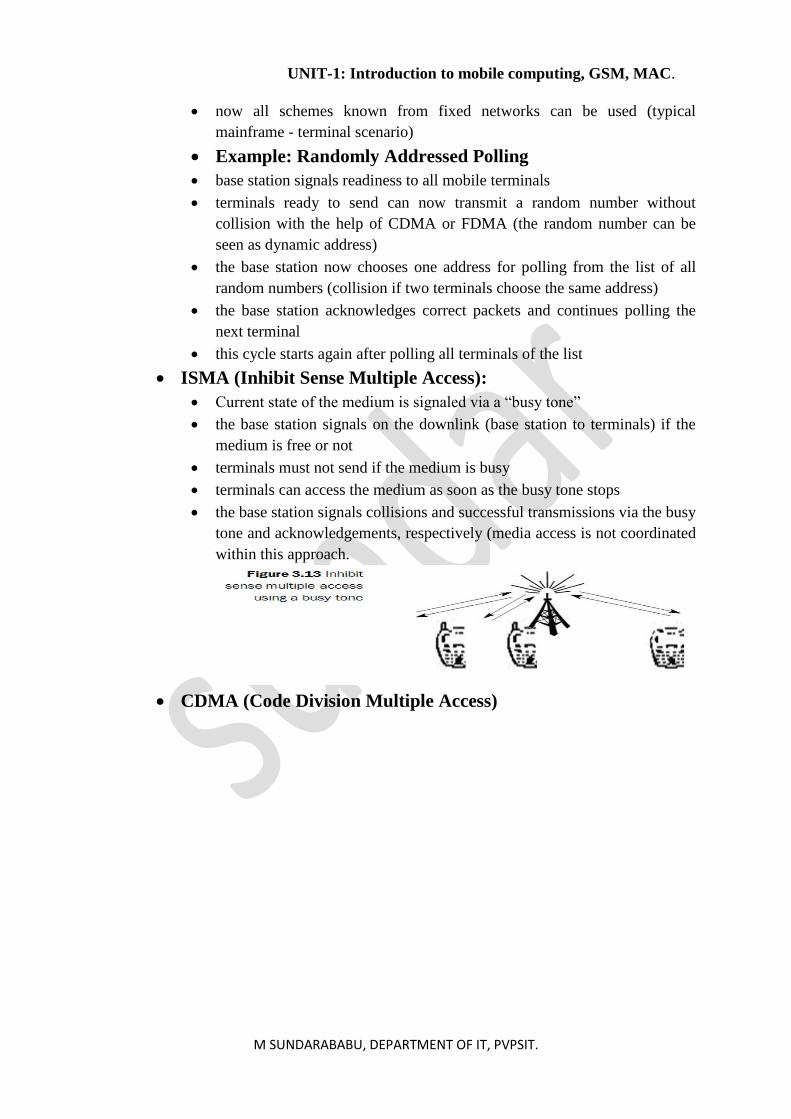
• ISMA (Inhibit Sense Multiple Access):
• Current state of the medium is signaled via a “busy tone”
• the base station signals on the downlink (base station to terminals) if the
medium is free or not
• terminals must not send if the medium is busy
• terminals can access the medium as soon as the busy tone stops
• the base station signals collisions and successful transmissions via the busy
tone and acknowledgements, respectively (media access is not coordinated
within this approach.
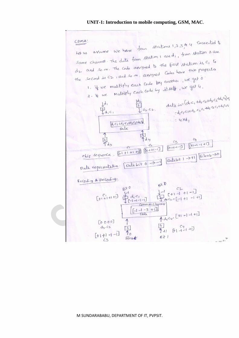
• CDMA (Code Division Multiple Access)
UNIT-1: Introduction to mobile computing, GSM, MAC.
M SUNDARABABU, DEPARTMENT OF IT, PVPSIT.
UNIT-1: Introduction to mobile computing, GSM, MAC.
M SUNDARABABU, DEPARTMENT OF IT, PVPSIT.
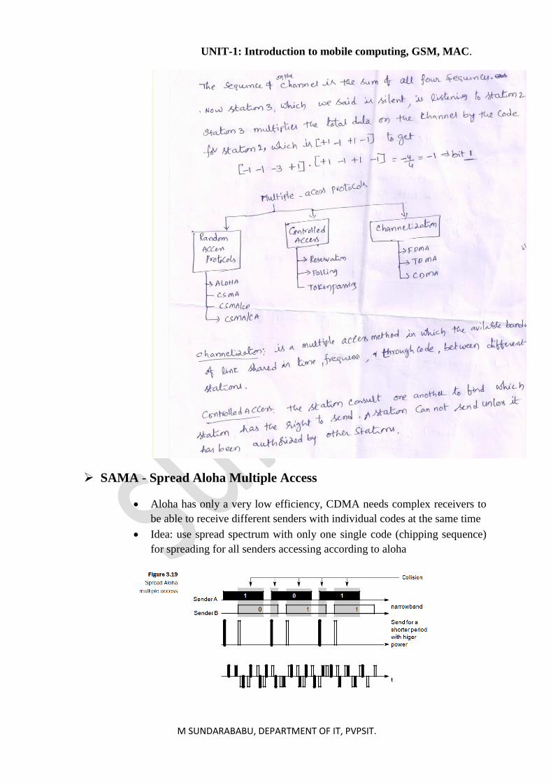
➢ SAMA - Spread Aloha Multiple Access
• Aloha has only a very low efficiency, CDMA needs complex receivers to
be able to receive different senders with individual codes at the same time
• Idea: use spread spectrum with only one single code (chipping sequence)
for spreading for all senders accessing according to aloha