Embed Size (px)
Citation preview
Unistrut Installation Guide
238 Cherry St, Shrewsbury, MA 01545 • freestylesystems.com • 508-845-4911 • fax: 508-845-4914
Copyright © Freestyle Systems LLC All Rights Reserved.

Important things to know about your Freestylist
Freestylesystems.com • Tel. 508.845.4911
Freestyle Systems
Electrical Power Requirement
Each unit should be on its own 120V AC 15-amp dedicated circuit. When applicable, the existing wall circuit may be redirected to the ceiling to power your Freestylist. Proper location makes all the difference
The Freestylist should always be installed so the dryer is suspended directly above the client’s head when seated. Location instructions should be followed carefully.
Proper installation height:
The Freestylist is manufactured for your specific installation height. After you and the Freestyle Systems specialist have determined your proper installation height, do not deviate from it. If you need to change the height, it must be done before the Freestylist is manufactured to your salon specifications. The recommended installation height for the Freestylist is between 8 and 12 feet from the floor. Light Platforms, however, need to be between 8 and 9.5 feet for optimal Spectralight performance.
Proper “weight” adjustment
Extensive testing has shown that the dryer should be adjusted so it floats downward very slowly when you let go of it at chest height. Your Freestylist is adjusted at the factory to this specification. If you want to change this or any other factory setting, pay close attention to the instructions in this booklet for adjusting your Freestylist.
Proper “resting position” height adjustment:
The Freestylist is equipped with internal height adjustment capabilities for the “resting position”. The Freestylist is installed at the predetermined installation height, but it can be easily adjusted for short or tall people. Adjustment instructions are included in this booklet. The Freestylist is equipped with a brake that engages when the dryer is raised to its resting position. (Note: The resting position is where the brake engages preventing the dryer from inadvertantly drifting downward and electrical power to the dryer is turned off by the Freestylist).Planning a new Salon?
Make sure your architect or designer knows exactly where your styling chairs will be. This will allow them to provide an unobstructed installation location.
Installing in an existing salon?
Check each location above the styling chairs for possible installation obstructions.
Important! Dryer Location Instructions
'Dryer should be suspended directly above client's head.The suggested MINIMUM distance from the mirror is 48"
" to 5 "
Important ! Dryer Location Instructions
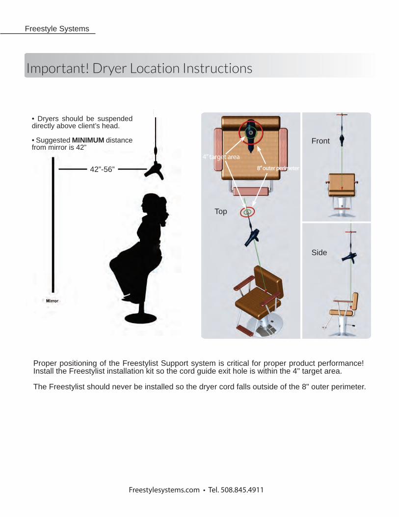
42”-56”
Freestyle Systems
Proper positioning of the Freestylist Support system is critical for proper product performance! Install the Freestylist installation kit so the cord guide exit hole is within the 4" target area.
The Freestylist should never be installed so the dryer cord falls outside of the 8" outer perimeter.
Freestylesystems.com • Tel. 508.845.4911
Front
Side
Top
8” outer perimeter
4” target area
• Dryers should be suspended directly above client’s head.
• Suggested MINIMUM distance from mirror is 42”
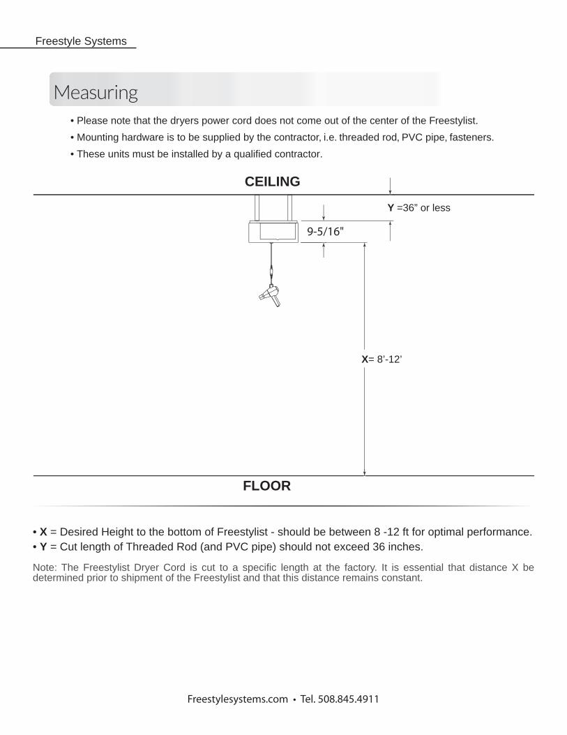
9-5/16"
FLOOR
CEILING
Measuring
Freestyle Systems
• Please note that the dryers power cord does not come out of the center of the Freestylist.
• Mounting hardware is to be supplied by the contractor, i.e. threaded rod, PVC pipe, fasteners.
• These units must be installed by a qualified contractor.
X= 8’-12’
Y =36” or less
• X = Desired Height to the bottom of Freestylist - should be between 8 -12 ft for optimal performance.• Y = Cut length of Threaded Rod (and PVC pipe) should not exceed 36 inches.
Note: The Freestylist Dryer Cord is cut to a specific length at the factory. It is essential that distance X be determined prior to shipment of the Freestylist and that this distance remains constant.
Freestylesystems.com • Tel. 508.845.4911
Parts List
Warranty
Freestyle Systems
Freestylesystems.com • Tel. 508.845.4911
What is covered: The warranty covers any defects in materials or workmanship in the Freestyl-ist Support System and the Freestylist Remote Control. Freestylist Support System = 2 years after product shipping date. Freestylist Remote Control = 90 days after product shipping date. Freestyle Systems will repair or replace any malfunctioning Freestylist Support Sstem or Free-stylist Remote Control within the warranty period at no charge.
Warranty does not cover damage done to the Freestylist Support System or the Remote Control caused by misuse, water penetration, impact, power surges, or attachment of any device not approved by Freestyle Systems. Any modifications to the Freestylist Support System or the Freestylist Remote Control by the customer voids the warranty. Attempts to repair the Freestylist Support System or the Freestylist Remote Control by the customer void the warranty. Blow Dryers carry their own warranties.
Extended Warranties available: 2 additional years (4 years total)
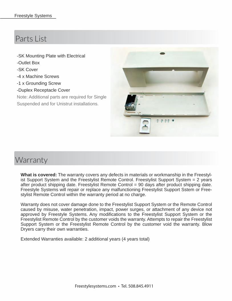
-SK Mounting Plate with Electrical
-Outlet Box
-SK Cover
-4 x Machine Screws
-1 x Grounding Screw
-Duplex Receptacle Cover
Note: Additional parts are required for Single
Suspended and for Unistrut installations.
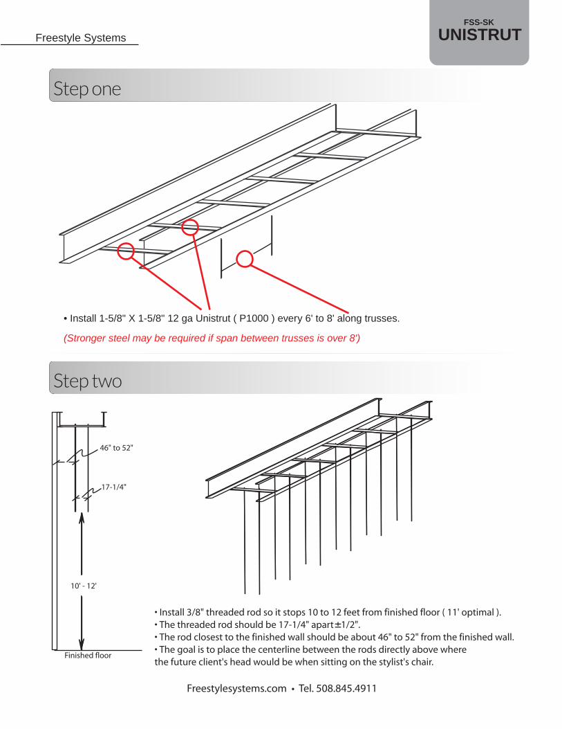
Step one
Step two
Freestylesystems.com • Tel. 508.845.4911
Freestyle Systems
• Install 1-5/8" X 1-5/8" 12 ga Unistrut ( P1000 ) every 6' to 8' along trusses.
(Stronger steel may be required if span between trusses is over 8')
Finished floor
10' - 12'
17-1/4"
46" to 52"
• Install 3/8" threaded rod so it stops 10 to 12 feet from finished floor ( 11' optimal ).• The threaded rod should be 17-1/4" apart ± 1/2". • The rod closest to the finished wall should be about 46" to 52" from the finished wall. • The goal is to place the centerline between the rods directly above where the future client's head would be when sitting on the stylist's chair.
UNISTRUTFSS-SK

Step three
Freestylesystems.com • Tel. 508.845.4911
Freestyle Systems
Step four
• Install long lengths of P1000 Unistrut to the bottom of the threaded rods with the opening U shape down
• Optional 1-1/4" PVC tubing or steel tubing can be installed on the outside of the threaded rod for decorative purposes.
Unistrut channel nutPart # P3006-1024 for use
with P1000 Unistrut
1-5/8" channels
Cord alignment hole
Knock-outs
• Attach Unistrut channel nuts ( not provided ) to the FSS-SK mounting plate. • Attach the mounting plate to the Unistrut channel. • Position cord alignment hole over the stylist's chair's backrest or directly abovewhere the future client's head would be when having their hair done. • Run electrical wires through one of the 4 knockouts provided.• Install a 20 amp,120V outlet to the box provided. • Each Freestylist unit should be on its own 20 amp circuit.
UNISTRUTFSS-SK

Step five
Freestylesystems.com • Tel. 508.845.4911
Freestyle Systems
• Mounting plates tie Unistrut channels together. • Finish wiring and painting. • Install Freestylist unit onto mounting plate.
UNISTRUTFSS-SK
Step six: Mounting Freestylist and Installing Cover
Freestylesystems.com • Tel. 508.845.4911
Freestyle Systems
• Install decorative cover by removing all the main cover screws except for the center screws.• When decorative cover is in place use the cover screws that were just removed to fasten it onto the Freestylist. • Plug in the dryer using the Freelock™ connector.
• Attach Freestylist support system to mounting plate using4, 10-32 machine screws. (Provided)
• Plug in electrical cord• Plug the diode into the mating plug
UNISTRUTFSS-SK
diode
8-3/8"
6-7/8" 10-15/16"
7-7/
8"8-
1/2"
18"
16-3
/8"
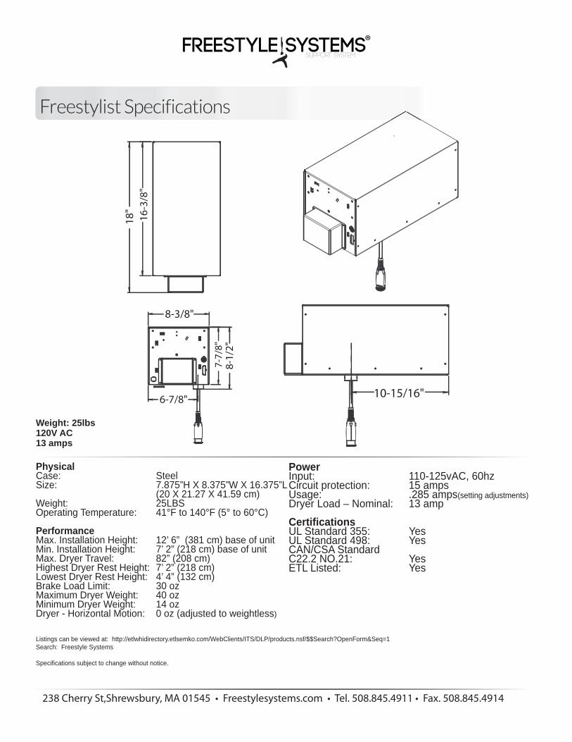
Weight: 25lbs120V AC13 amps
Freestylist Specifications
238 Cherry St,Shrewsbury, MA 01545 • Freestylesystems.com • Tel. 508.845.4911 • Fax. 508.845.4914
PhysicalCase: Steel Size: 7.875”H X 8.375”W X 16.375”L (20 X 21.27 X 41.59 cm) Weight: 25LBS Operating Temperature: 41°F to 140°F (5° to 60°C)
PerformanceMax. Installation Height: 12’ 6” (381 cm) base of unit Min. Installation Height: 7’ 2” (218 cm) base of unit Max. Dryer Travel: 82” (208 cm) Highest Dryer Rest Height: 7’ 2” (218 cm) Lowest Dryer Rest Height: 4’ 4” (132 cm) Brake Load Limit: 30 oz Maximum Dryer Weight: 40 oz Minimum Dryer Weight: 14 oz Dryer - Horizontal Motion: 0 oz (adjusted to weightless)
Listings can be viewed at: http://etlwhidirectory.etlsemko.com/WebClients/ITS/DLP/products.nsf/$$Search?OpenForm&Seq=1Search: Freestyle Systems
Specifications subject to change without notice.
PowerInput: 110-125vAC, 60hz Circuit protection: 15 amps Usage: .285 amps(setting adjustments)Dryer Load – Nominal: 13 amp
CertificationsUL Standard 355: Yes UL Standard 498: Yes CAN/CSA Standard C22.2 NO.21: Yes ETL Listed: Yes


![Unistrut 16 Catalog[1]](https://img.pdfslide.us/doc/110x75/544dea9eaf7959f3138b52c7/unistrut-16-catalog1.jpg)