Embed Size (px)
Citation preview
DESIGN DEVELOPMENT REPORT | SEPTEMBER 2007 UniSA | MAWSON INSTITUTE OF ADVANCED MANUFACTURING | BUILDING V
DESIGN DEVELOPMENT REPORT | SEPTEMBER 2007
UniS
A| M
AWSO
N IN
STIT
UTE
OF A
DVAN
CED
MAN
UFAC
TURI
NG |
BUIL
DING
V
2
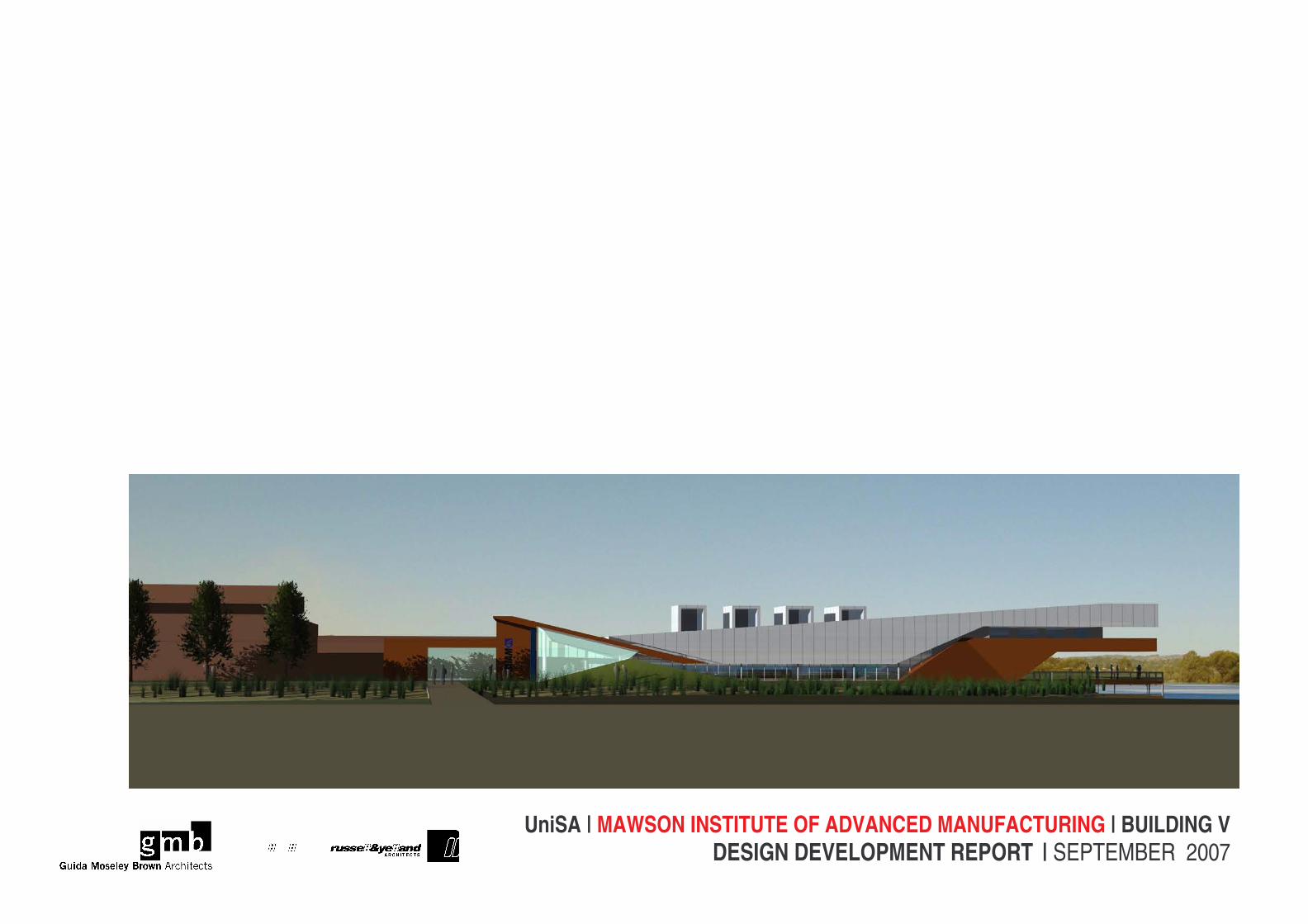
1 INTRODUCTION The proposal is to provide a new building to accommodate the Mawson Institute of Advanced Manufacturing (MIAM) at the Mawson Lakes Campus of University of South Australia (UniSA). Currently MIAM is housed in temporary accommodation in Buildings C and R at the Mawson Lakes Campus (refer Appendix A). The work will include the construction of a new building of predominately single level construction located on a site to the east of Building M. This location has been selected due to the current and future research linkages and opportunities with the research activities contained within Building M. The new building will accommodate both the laboratory and office accommodation needs of MIAM. It will be in the order of 1880m² Gross Floor Area (GFA), comprising approximately 1000 sq.m. of administrative facilities and 890 sq.m. of laboratories. Extensions to the existing campus site infrastructure, such as provision of a new chiller, extension of the existing hot and chilled pipe-work, power supply via a new culvert and loading/ deliveries area will also be required to service this new building. The University of South Australia and the SA Department of Further Education, Employment, Science and Technology have jointly funded this project. The University acknowledges the Kaurna people as the traditional owners of this land and acknowledges their living culture and unique role in the life of this region. Contents: 1 INTRODUCTION 2 2 PROJECT TEAM 3 3 PROJECT OBJECTIVES 4 4 SITE AND ORIENTATION 5 5 LANDSCAPE 6 6 INTERIOR DESIGN 8 7 INTERIOR FURNITURE & JOINERY 9 8 LABORATORY DESIGN 10 9 MAINTENANCE 11 10 CONSULTATION PROCESS 12 11 RISK MANAGEMENT 13 12 OCCUPATIONAL HEALTH AND SAFETY 16 13 DISABILITY ACCESS 23 14 ENGINEERING SERVICES 25 15 ACOUSTICS 28 16 STRUCTURAL REPORT & DOCUMENTATION 32 17 LANDSCAPE 35 18 GREEN STAR AND ESD INTIATIVES 38 19 Heritage Status 41 20 PARKING 42 21 COST PLAN 43 APPENDIX A - FINISHES AND AREA SCHEDULE 47 APPENDIX B: RISK MATRIX 50 APPENDIX C: EXTERNAL SAMPLE BOARD 53 APPENDIX D: MEETINGS SCHEDULE 54 APPENDIX E: PROGRAM 56 APPENDIX F: GREEN STAR MATRIX 57 APPENDIX G: ROOM DATA SHEETS 58 APPENDIX H: DRAWINGS 59
DESIGN DEVELOPMENT REPORT | SEPTEMBER 2007
UniS
A| M
AWSO
N IN
STIT
UTE
OF A
DVAN
CED
MAN
UFAC
TURI
NG |
BUIL
DING
V
3
2 PROJECT TEAM The project team for the Mawson Institute of Advanced Manufacturing is as follows: UniSA Project Manager Christina Coleiro/Kobus Pienaar
Architects in Association Guida Moseley Brown Architects
Russell & Yelland Architects
Laboratory Consultants Brian Griffin Laboratory Consultant
Mechanical, Electrical, Hydraulics, Acoustics and Communications Engineers Bassett Consulting Engineers
Structural and Civil Engineers Wallbridge & Gilbert
Landscape Architects Taylor Cullity & Lethlean
ESD and Green Star Professionals Sustainable Built Environments
Cost Planning Rider Levett Bucknall
Risk Management Russell & Yelland Architects and Bassett
Consulting Engineers
Disability Access Disability Consultancy Services Pty Ltd.
Building Certifiers Katnich Dodd
Construction Programming Round Table Pty Ltd
DESIGN DEVELOPMENT REPORT | SEPTEMBER 2007
UniS
A| M
AWSO
N IN
STIT
UTE
OF A
DVAN
CED
MAN
UFAC
TURI
NG |
BUIL
DING
V
4
3 PROJECT OBJECTIVES
3.1 The Client’s Requirements The client for the Mawson Institute for Advanced Manufacturing comprises a number of stakeholders who have contributed towards funding and briefing processes. The client group consists of: • The University of South Australia requiring laboratory and office accommodation for new areas of research in Biology & Materials and
Pre-Commercialisation and existing research bodies within the University, Centre for Advanced Manufacturing and Research (CAMR), Ian Wark Research Institute and the Advanced Computing Research Centre (ACRC).
• The State Government of South Australia, Building Management, Department of Transport, Energy & Infrastructure (DTEI) The project therefore provides a unique opportunity for collaboration to create new partnerships between existing research bodies within the University and the state government.
3.2 Landmark Building The Mawson Institute for Advanced Manufacturing is a significant new building on the campus both for what it is (the bringing together of different areas of research within the university) and where it is (one of the first buildings on the Eastern Edge of the campus to engage with the landscape ‘edge’ of the campus. The aspirations of the project team are that the function of the building and its landscape provide an opportunity for a unique design response. In its form, the project team intends the building should represent the ideals and motivations which the researchers working within will pursue in their own work.
3.3 Project Scope The project comprises the design, documentation and construction of the Mawson Institute for Advanced Manufacturing itself, landscaping to the immediate surrounds and linking in with the University master plan works for the ‘A13’ courtyard precinct and surrounds including the extension of the man-made swale.
3.4 Codes & Regulations The project is governed by the following: • University of South Australia’s Design and Construction Guidelines – V2.0 January 2007. • The Building Code of Australia and the various codes and standards that are referenced by that document. • The Planning Regulations of the City of Salisbury. • The Federal Department of Aviation, which has jurisdiction over the nearby Parafield Airport. • All other codes and standards as applicable to the project.
3.5 Budget The project budget is A$ 11,250,000 plus GST. The construction budget is $7,386,000 and FF&E budget is $1,256,000 plus GST.
3.6 Schedule The project requires documentation complete by December 2007, Tenders Close February 2008 and Completion prior to June 2009. Refer to Appendix C - Program
3.7 Delivery Approach The project will be lump tendered by the University of South Australia with the Architect as Superintendent and the University of South Australia as Principal.
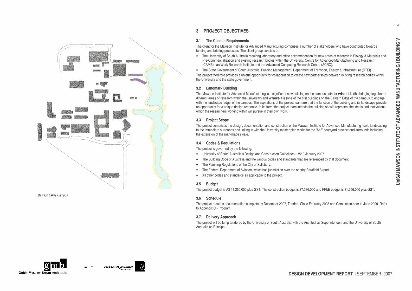
Mawson Lakes Campus
DESIGN DEVELOPMENT REPORT | SEPTEMBER 2007
UniS
A| M
AWSO
N IN
STIT
UTE
OF A
DVAN
CED
MAN
UFAC
TURI
NG |
BUIL
DING
V
5
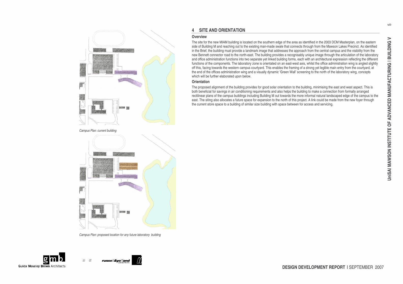
4 SITE AND ORIENTATION Overview The site for the new MIAM building is located on the southern edge of the area as identified in the 2003 DCM Masterplan, on the eastern side of Building M and reaching out to the existing man-made swale that connects through from the Mawson Lakes Precinct. As identified in the Brief, the building must provide a landmark image that addresses the approach from the central campus and the visibility from the new Bennett connector road to the north-east. The building provides a recognisably unique image through the articulation of the laboratory and office administration functions into two separate yet linked building forms, each with an architectural expression reflecting the different functions of the components. The laboratory zone is orientated on an east-west axis, whilst the office administration wing is angled slightly off this, facing towards the western campus courtyard. This enables the framing of a strong yet legible main entry from the courtyard, at the end of the offices administration wing and a visually dynamic ‘Green Wall’ screening to the north of the laboratory wing, concepts which will be further elaborated upon below. Orientation The proposed alignment of the building provides for good solar orientation to the building, minimising the east and west aspect. This is both beneficial for savings in air conditioning requirements and also helps the building to make a connection from formally arranged rectilinear plans of the campus buildings including Building M out towards the more informal natural landscaped edge of the campus to the east. The siting also allocates a future space for expansion to the north of this project. A link could be made from the new foyer through the current store space to a building of similar size building with space between for access and servicing.
Campus Plan: current building
Campus Plan: proposed location for any future laboratory building
DESIGN DEVELOPMENT REPORT | SEPTEMBER 2007
UniS
A| M
AWSO
N IN
STIT
UTE
OF A
DVAN
CED
MAN
UFAC
TURI
NG |
BUIL
DING
V
6
5 LANDSCAPE The building follows the Taylor Cullity Lethlean 2006 Landscape masterplan of the ‘Precinct A13 – Building M Green / Meadow’ which will extends the man-made swale into the courtyard, surrounded by buildings M, OC, J, K, PH and west of building P. Further descriptions of the Landscape design can be found in the ‘Landscape’ section. The main entry to the building and foyer is located at the end of a pathway that leads the visitor / user through the centre of the courtyard. Part of this work will be initiated by the university outside of this project that will help initiate the full realisation of the masterplan and engagement of the new MIAM building with the landscape. By locating the building in line with the edge of the existing building M helps to reinforce the definition of this courtyard space. This engagement of the building with the landscape will also establish a unique setting and environment for this building and it is one of the first on this campus to take advantage of such a link.
5.1 External Design Concepts The design for the Mawson Institute of Advanced Manufacturing is based upon two near parallel linear wings that provide for highly organized and flexible laboratory accommodation in one wing and for offices and support accommodation in differing patterns in the other. The linking space provides for access and circulation and is intended to be an open social place inviting and supporting informal interaction between researchers, administration, and occasional visitors. The relationship between the laboratories and the office areas is efficient and practical but with openness, visibility, direct access and interaction over three dimensions. Basically the plan of the office wing has been designed as a single level "folded" over two storeys. A single slope sloping roof helps in the creation and definition of this space. Rather than compete with the vertical scale of the adjacent Building M, the new MIAM building expresses itself horizontally, in a manner more appropriate for the landscape around. To emphasis the horizontality, a large overhanging roof form over the west entry provides shade and shelter, whilst mediating the scale of Building M. To the east, the floor plate steps to create a dramatic cantilever over the man-made swale. This creates a unique opportunity for outdoor space on the campus that is both protected and able to fully appreciate the natural environment from an outdoor deck. The Large Meeting Room is positioned so that is it easily accessible from other places on the campus, and a large sculptural earth berm assists in joining the building with the landscape, and mitigates what might otherwise be a disrupting building mass. This planted landform helps engage the building directly to the wide open landscape, landscape that is unique to this precinct of the campus, and other building forms are similarly grounded so as to provide a base from which the “soaring” roof form can arise.
5.2 Description of External Materials & Philosophy The use of two different characters of materials is intended to emphasize the articulated building forms and characteristics and the significant cantilever which provides the distinctive profile and identity of the building. The materials proposed are suited to help make this linkage to the landscape; all low elements are envisaged in earth-coloured cementitious panels, whilst the roof-form is shiny silver metal: stainless steel sheet or silver coated steel panels. The treatment of glazed walls on the western elevation has varying levels of opacity to explore the definition between private and public spaces and connectivity between the two. The use of glass channels with a slight sand blasted texture to diffuse the light passing through provides a level of privacy to the large meeting room, but still enables a sense of light penetration. A generous twelve metre wide by three metre high opening of clear glass provides a focus towards the entry, providing clear indication of the entry door, visibility to the foyer and the entry of the meeting room. In other areas the glass channel have a solid drywall partition behind to provide a softer variance of colour but united as a surface through the use of the glass channel throughout the western elevation, pre-commercialisation lab and large meeting room.
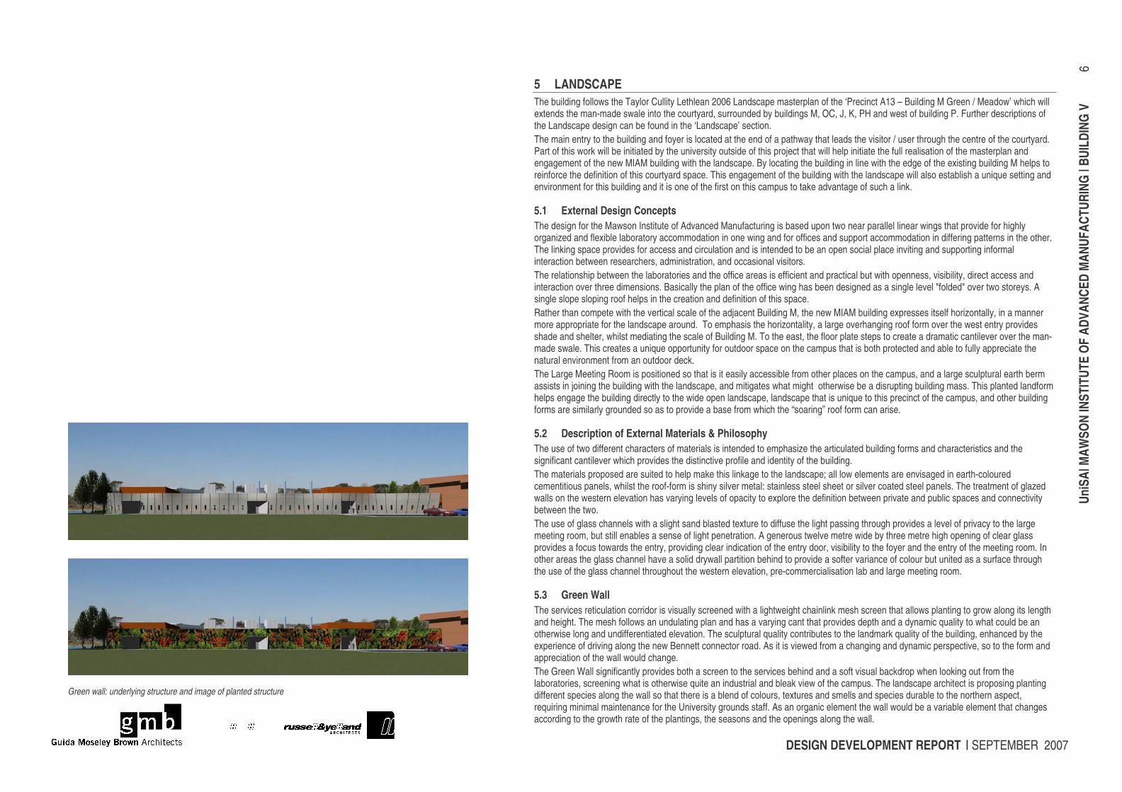
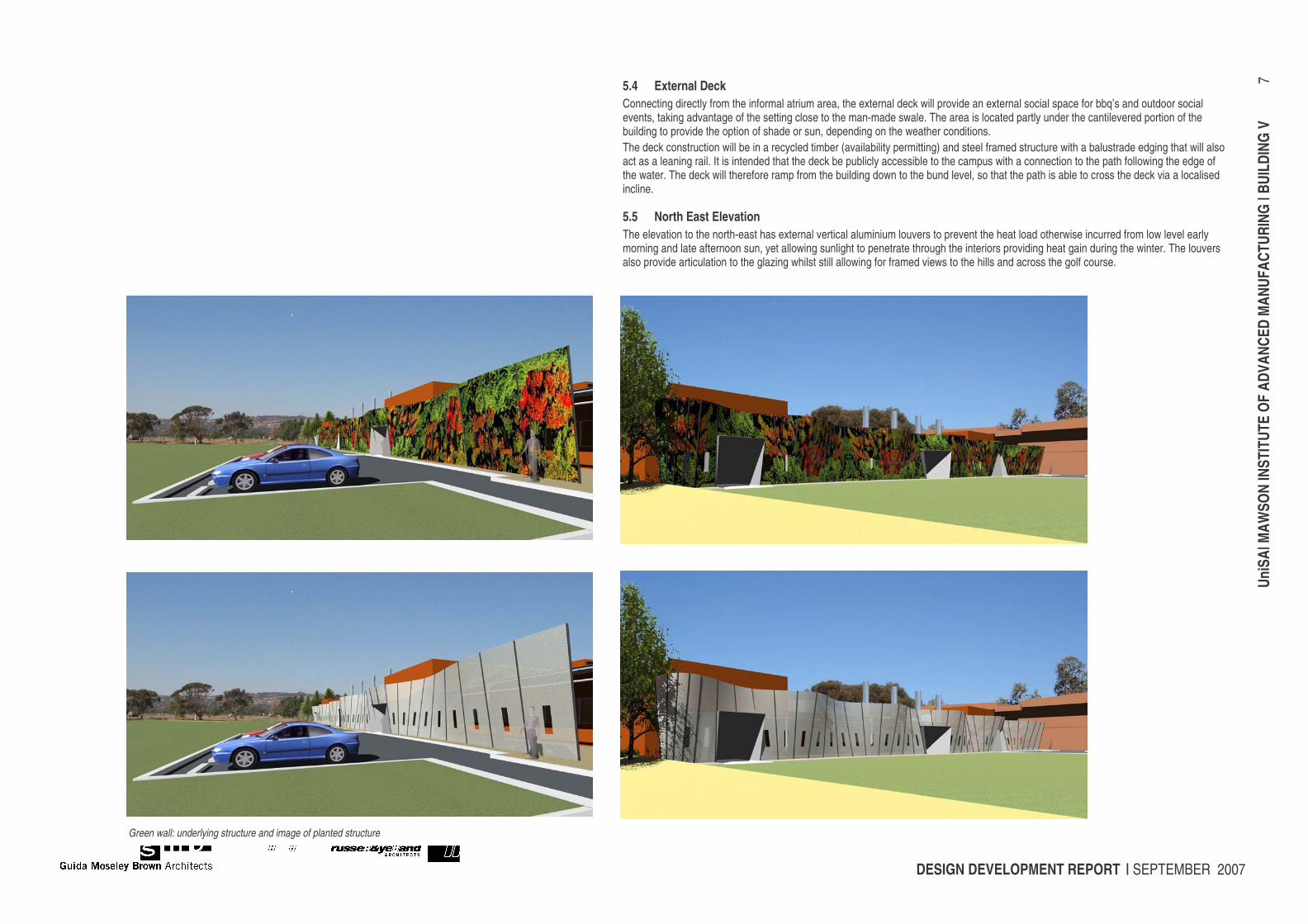
5.3 Green Wall The services reticulation corridor is visually screened with a lightweight chainlink mesh screen that allows planting to grow along its length and height. The mesh follows an undulating plan and has a varying cant that provides depth and a dynamic quality to what could be an otherwise long and undifferentiated elevation. The sculptural quality contributes to the landmark quality of the building, enhanced by the experience of driving along the new Bennett connector road. As it is viewed from a changing and dynamic perspective, so to the form and appreciation of the wall would change. The Green Wall significantly provides both a screen to the services behind and a soft visual backdrop when looking out from the laboratories, screening what is otherwise quite an industrial and bleak view of the campus. The landscape architect is proposing planting different species along the wall so that there is a blend of colours, textures and smells and species durable to the northern aspect, requiring minimal maintenance for the University grounds staff. As an organic element the wall would be a variable element that changes according to the growth rate of the plantings, the seasons and the openings along the wall.
Green wall: underlying structure and image of planted structure
DESIGN DEVELOPMENT REPORT | SEPTEMBER 2007
UniS
A| M
AWSO
N IN
STIT
UTE
OF A
DVAN
CED
MAN
UFAC
TURI
NG |
BUIL
DING
V
7
5.4 External Deck Connecting directly from the informal atrium area, the external deck will provide an external social space for bbq’s and outdoor social events, taking advantage of the setting close to the man-made swale. The area is located partly under the cantilevered portion of the building to provide the option of shade or sun, depending on the weather conditions. The deck construction will be in a recycled timber (availability permitting) and steel framed structure with a balustrade edging that will also act as a leaning rail. It is intended that the deck be publicly accessible to the campus with a connection to the path following the edge of the water. The deck will therefore ramp from the building down to the bund level, so that the path is able to cross the deck via a localised incline.
5.5 North East Elevation The elevation to the north-east has external vertical aluminium louvers to prevent the heat load otherwise incurred from low level early morning and late afternoon sun, yet allowing sunlight to penetrate through the interiors providing heat gain during the winter. The louvers also provide articulation to the glazing whilst still allowing for framed views to the hills and across the golf course.
Green wall: underlying structure and image of planted structure
DESIGN DEVELOPMENT REPORT | SEPTEMBER 2007
UniS
A| M
AWSO
N IN
STIT
UTE
OF A
DVAN
CED
MAN
UFAC
TURI
NG |
BUIL
DING
V
8
6 INTERIOR DESIGN
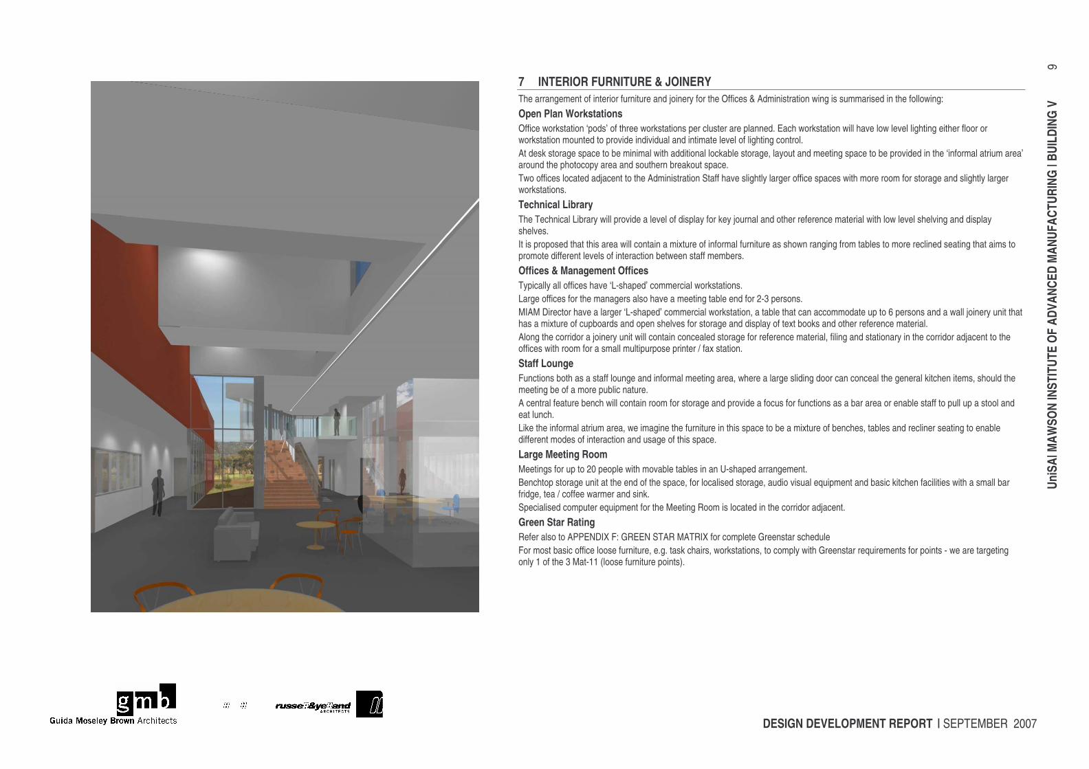
6.1 Overview The internal linking space originates at the western campus-side entrance and ‘widens’ as it leads to the staff Meeting Room overlooking the water bodies and freeform landscape at the East. Over the distance the single floor level “rises” to what may be seen as a mezzanine, creating a three dimensional space and allowing for intensified interaction. The upper level cantilevers out above the landscaped swale and water and allows for long distance views from this location. The central space is marked and provided natural light from four large roof monitors, which externally create a distinct profile in relationship to the long sloping roof. The office groupings at the ground are arranged so as to enhance the connectedness from the open office area to the upper area; the generous stair (width and low riser dimension) is part of both areas and leads directly to the Staff Meeting Room. The staff room faces the stair and the lower floor so that the whole space is opened-up to work as one and allow interactivity of functions between the two. The upper level contains the MIAM director and managers in slightly larger offices that are visible to the lower work area. The close proximity to the staff lounge enables for the usage of this space for informal meetings and a glazed door at the entry of the offices space provides a level of privacy between the two spaces.
6.2 Interior Partitions Throughout the building, a standard dry-wall partitioning system incorporating acoustic insulation is proposed. Around those rooms which require increased privacy and sound insulation, the mass of partition systems will be increased and extended up to the underside of slab or structure. These include the offices for the two researchers adjacent to the entry, the Managers, Personal Assistant and the Director of MIAM. Laminated glazing will be used extensively between offices and circulation spaces to maintain a feeling of openness and transparency throughout the building.
6.3 Room Designs Room sizes and characteristics were determined initially by the brief. The proposed construction, layout, materials and components also follow the requirements setout in the new University of South Australia’s Design and Construction Guidelines – V2.0 January 2007 and Reference Group Meetings. The current brief is an amalgam of the following documents • Original Briefing Document dated January 2007 • Briefing Supplement dated Wednesday 7th March 2007 The current design attempts to emphasise the quality of open shared space with a number of storage and kitchen areas consolidated into the open space or the staff lounge to maximise their efficiency. A comparison of briefed versus actual areas is incorporated at Appendix A.
DESIGN DEVELOPMENT REPORT | SEPTEMBER 2007
UniS
A| M
AWSO
N IN
STIT
UTE
OF A
DVAN
CED
MAN
UFAC
TURI
NG |
BUIL
DING
V
9
7 INTERIOR FURNITURE & JOINERY The arrangement of interior furniture and joinery for the Offices & Administration wing is summarised in the following: Open Plan Workstations Office workstation ‘pods’ of three workstations per cluster are planned. Each workstation will have low level lighting either floor or workstation mounted to provide individual and intimate level of lighting control. At desk storage space to be minimal with additional lockable storage, layout and meeting space to be provided in the ‘informal atrium area’ around the photocopy area and southern breakout space. Two offices located adjacent to the Administration Staff have slightly larger office spaces with more room for storage and slightly larger workstations. Technical Library The Technical Library will provide a level of display for key journal and other reference material with low level shelving and display shelves. It is proposed that this area will contain a mixture of informal furniture as shown ranging from tables to more reclined seating that aims to promote different levels of interaction between staff members. Offices & Management Offices Typically all offices have ‘L-shaped’ commercial workstations. Large offices for the managers also have a meeting table end for 2-3 persons. MIAM Director have a larger ‘L-shaped’ commercial workstation, a table that can accommodate up to 6 persons and a wall joinery unit that has a mixture of cupboards and open shelves for storage and display of text books and other reference material. Along the corridor a joinery unit will contain concealed storage for reference material, filing and stationary in the corridor adjacent to the offices with room for a small multipurpose printer / fax station. Staff Lounge Functions both as a staff lounge and informal meeting area, where a large sliding door can conceal the general kitchen items, should the meeting be of a more public nature. A central feature bench will contain room for storage and provide a focus for functions as a bar area or enable staff to pull up a stool and eat lunch. Like the informal atrium area, we imagine the furniture in this space to be a mixture of benches, tables and recliner seating to enable different modes of interaction and usage of this space. Large Meeting Room Meetings for up to 20 people with movable tables in an U-shaped arrangement. Benchtop storage unit at the end of the space, for localised storage, audio visual equipment and basic kitchen facilities with a small bar fridge, tea / coffee warmer and sink. Specialised computer equipment for the Meeting Room is located in the corridor adjacent. Green Star Rating Refer also to APPENDIX F: GREEN STAR MATRIX for complete Greenstar schedule For most basic office loose furniture, e.g. task chairs, workstations, to comply with Greenstar requirements for points - we are targeting only 1 of the 3 Mat-11 (loose furniture points).
DESIGN DEVELOPMENT REPORT | SEPTEMBER 2007
UniS
A| M
AWSO
N IN
STIT
UTE
OF A
DVAN
CED
MAN
UFAC
TURI
NG |
BUIL
DING
V
10
8 LABORATORY DESIGN The arrangement of the Laboratory Wing is a result of extensive briefing sessions with each of the user groups and the refinement of layouts in collaboration with the Laboratory Consultant and Architect Brian Griffin and the user representative David Steele. The design emphasises proposals for maximum flexibility so as to allow future alterations to the internal layouts with minimal disruption to structure and services. It allows for major reorganisation within the entire wing and future expansion to the north of the building. Refer also to Appendix D – Room Data Sheets To summarise how this has been included in the design: • The provision of an external covered services reticulation zone to the north with Mechanical, Electrical, Hydraulic and Fire Services all
exposed and accessible. • All internal partitions are non load bearing between laboratories to enable alteration of the layouts. • Internal benching layouts are arranged on a 3000 grid with 1500mm bench modules and 1500mm aisle clearance with no less than
1350 clear aisle space between two desks. • Modular strip window to the north elevation with removable infill panels at wall junctions to conceal major mechanical and electrical
installation. • Exposed ductwork in the lab spaces. • Modular sized and movable internal benches and a services spine to enable services to be carried internally for ease of access and
alteration. All benches are either 1500 x 600 and 1500 x 750, made from a solid surface material such as Corian or Chemform. • A lined and lightweight framed wall to the north of the building to enable ease of services penetrations and their alteration for future • Suspended, indirect lighting to 600lux with 800 lux to the CAMR lab. • Skylights to each laboratory for daylight access deep in to the plan, with remote coverings where required. • Sun-shading to the labs to comply with AS 2982
DESIGN DEVELOPMENT REPORT | SEPTEMBER 2007
UniS
A| M
AWSO
N IN
STIT
UTE
OF A
DVAN
CED
MAN
UFAC
TURI
NG |
BUIL
DING
V
11
9 MAINTENANCE From the various Technical Reference meetings, the following maintenance provisions are to be incorporated into the building: • The roof is accessed via the services reticulation zone with an access stair leading up to plant room level and then separate stairs
providing access onto each main roof area. Crawl boards provide access to each of the main skylight and roof mounted solar hot-water units.
• Access to ceiling in internal offices is via a small scissor lift. This lift will be located either within the building or within Building M where there is more available storage area.
• The overhanging office area can be access from the external deck below with a small ladder, with ladder hanging points provided in the edge of the soffit. This will allow access will allow access to a majority of the glass or rear louvers should they need to be changed or cleaned. The remaining windows to the south elevation overhanging the water, can be accessed by a cherry picker should they need to be replaced.
• General external building materials have been selected that are durable and require little maintenance, such as the cementitious panel, stainless steel and glass. External soffits to the services reticulation zone on the labs will be exposed structure but enclosed by the green wall and bird / rodent proof mesh. For the higher quality areas, the cementitious panel wrapped under so that there is no requirement for repainting.
• The Green Wall is separated by a minimum of 600mm (ladder width or wider to suit final servicing requirements) and is greater in a majority of other areas. In elevation is rises to a maximum of 4000mm and has a maximum cant of 600mm, so to be within the height reach of a ladder and not far to reach out from the base position. The surface below is paved so to enable leaf and other materials to be easily removed with a leaf blower and provide a stable surface for maintenance. The external structure to the services reticulation zone will be enclosed with a bird and rodent proof mesh that also provides a minimum level of security to the services zone. - Documentation – A001 – A502 as they currently stand - Renderings (updated 5 from PCG presentations with Green Wall views)
DESIGN DEVELOPMENT REPORT | SEPTEMBER 2007
UniS
A| M
AWSO
N IN
STIT
UTE
OF A
DVAN
CED
MAN
UFAC
TURI
NG |
BUIL
DING
V
12
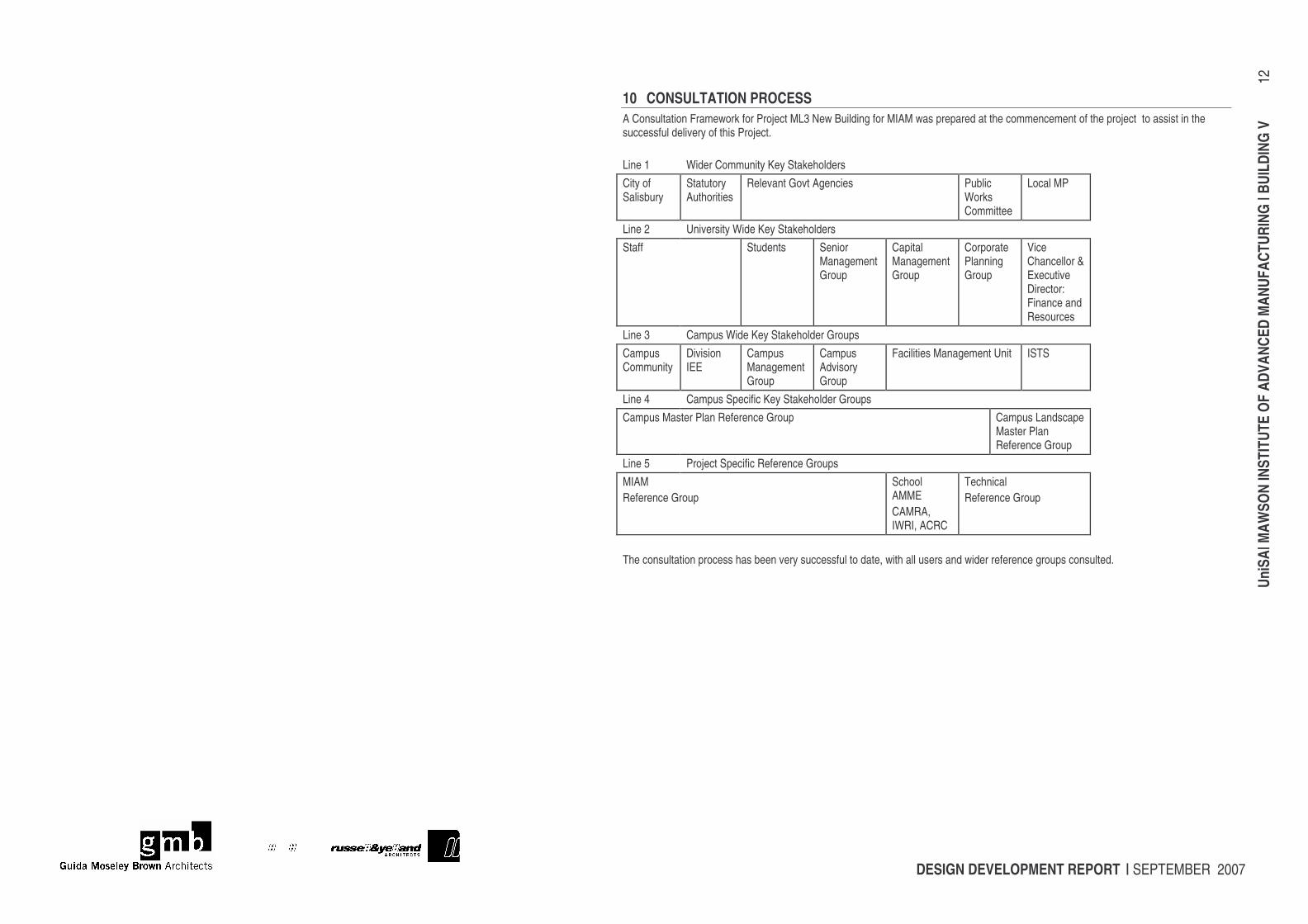
10 CONSULTATION PROCESS A Consultation Framework for Project ML3 New Building for MIAM was prepared at the commencement of the project to assist in the successful delivery of this Project. Line 1 Wider Community Key Stakeholders City of Salisbury
Statutory Authorities
Relevant Govt Agencies Public Works Committee
Local MP
Line 2 University Wide Key Stakeholders Staff Students Senior
Management Group
Capital Management Group
Corporate Planning Group
Vice Chancellor & Executive Director: Finance and Resources
Line 3 Campus Wide Key Stakeholder Groups Campus Community
Division IEE
Campus Management Group
Campus Advisory Group
Facilities Management Unit ISTS
Line 4 Campus Specific Key Stakeholder Groups Campus Master Plan Reference Group Campus Landscape
Master Plan Reference Group
Line 5 Project Specific Reference Groups MIAM Reference Group
School AMME CAMRA, IWRI, ACRC
Technical Reference Group
The consultation process has been very successful to date, with all users and wider reference groups consulted.
DESIGN DEVELOPMENT REPORT | SEPTEMBER 2007
UniS
A| M
AWSO
N IN
STIT
UTE
OF A
DVAN
CED
MAN
UFAC
TURI
NG |
BUIL
DING
V
13
11 RISK MANAGEMENT AS/NZS 4360:2004 (“the Standard”) outlines general structures for the management of risks. Identification management and assignation of the responsibilities for the reduction of risk are key factors to the success of this project. Risk identification is an evolving process and requires a regular structured review process.
11.1 Communication and Consultation The Standard identifies communication and consultation as being a key factor in the successful implementation of Risk Management. As such the following actions shall be taken by the Project Team
• Complete the project quality plan and communicate its contents to all members of the Project Team • Identify key stakeholders, both direct and indirect, in the project, and establish timely and effective means of communications
with all of them • Confirm lines of communication within the project team • Establish regular meeting schedules, and circulate minutes in a timely manner to relevant stakeholders • Establish a consultation plan to clearly define the responsibilities for communication and consultation, including projected
dates and participants, between indirect stakeholders such as future staff, students and community members.
11.2 Establishment of Context General The Standard notes that “establishing the context defines the basic parameters within which the risks must be managed and sets the scope for the rest of the risk management process. Establishing the external context The external context of the project is important, and includes the history and political context of the project. We propose that ACTPS provide a brief summary of the external context of the project as part of this risk plan. Establishing the internal context For the purposes of establishing the internal context of the project, the “organisation” referred to in the Standard is defined as the Project Team, namely Principal Consultant and secondary consultants. The key context of the organisation is described in the Project Quality Plan. Establishing the risk management context The risk management context for this project is defined in terms of an experienced project team with clear goals and clear time and cost targets. Thus the risk management plan should concentrate on
• Project-specific risks • Time constraints • Cost constraints • Specific issues relating to the construction contract, process and external influences such as the construction marketplace at
the time • Particular issues related to the external context of the project
Development of risk criteria Given the context described above, the key criteria to be considered will be project-specific risks related to time, cost, quality and scope. Risk evaluation will be assessed on a ordinal scale, as follows:
• Likelihood: high, medium, low • Consequence: high, medium, low
Define the structure for the rest of the process This can be considered as follows:
• Action list to complete this plan: refer to the Appendix to this plan • Review of risk management plan:
o As a regular part of meeting agendas
DESIGN DEVELOPMENT REPORT | SEPTEMBER 2007
UniS
A| M
AWSO
N IN
STIT
UTE
OF A
DVAN
CED
MAN
UFAC
TURI
NG |
BUIL
DING
V
14
o As a separate, structured activity at key milestones in the process o As part of the construction stage process.
11.3 Risk Identification Tools and Techniques The Risk Identification process commences with this Plan and it is proposed that a focussed risk identification meeting be held as a separate process towards the end of the first stage of the project. Issues to be considered include:
• Time, program and approvals periods • Scope changes, briefing clarifications and • Cost and budget issues • Design issues • Third-party approvals
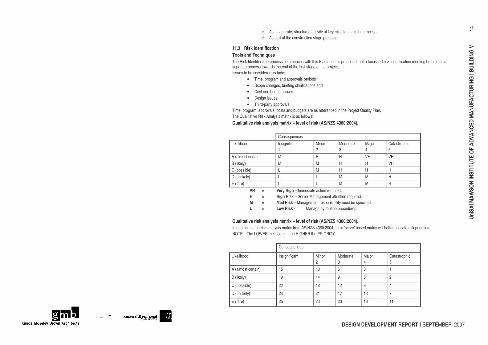
Time, program, approvals, costs and budgets are as referenced in the Project Quality Plan. The Qualitative Risk Analysis matrix is as follows: Qualitative risk analysis matrix – level of risk (AS/NZS 4360:2004).
Consequences
Likelihood Insignificant 1
Minor 2
Moderate 3
Major 4
Catastrophic 5
A (almost certain) M H H VH VH B (likely) M M H H VH C (possible) L M H H H D (unlikely) L L M M H E (rare) L L M M H
VH = Very High – Immediate action required. H = High Risk – Senior Management attention required. M = Med Risk – Management responsibility must be specified. L = Low Risk - Manage by routine procedures.
Qualitative risk analysis matrix – level of risk (AS/NZS 4360:2004). In addition to the risk analysis matrix from AS/NZS 4360:2004 – this ‘score’ based matrix will better allocate risk priorities. NOTE – The LOWER the ‘score’ – the HIGHER the PRIORITY.
Consequences
Likelihood Insignificant 1
Minor 2
Moderate 3
Major 4
Catastrophic 5
A (almost certain) 15 10 6 3 1
B (likely) 19 14 9 5 2
C (possible) 22 18 12 8 4
D (unlikely) 24 21 17 13 7
E (rare) 25 23 20 16 11
DESIGN DEVELOPMENT REPORT | SEPTEMBER 2007
UniS
A| M
AWSO
N IN
STIT
UTE
OF A
DVAN
CED
MAN
UFAC
TURI
NG |
BUIL
DING
V
15
These assessments are included as APPENDIX B: RISK MATRIX to this report.
11.4 Risk Analysis Methods of analysis In the context of this project it is not considered necessary to establish formal matrices or methods of scoring and analysis. Analysis will be qualitative and where significant risk issues are highlighted these will be separately addressed in detail as part of the Management system for the project, and have separate agenda items where necessary at a project control group level. It is proposed not to formally analyse opportunities in the same way as negative risks but to treat them as part of the management process. Documentation of the analysis Documentation of the analysis will be by the publishing and updating of the risk management matrix to the relevant stakeholders and by agenda and minute items in the regular meetings of the project team and Project Control Group. Risk Evaluation The evaluation of risks will be undertaken as part of the relevant risk management workshops and by subsequent consideration by both the Project Team and the Project Control Group. Decisions on the level of tolerable risk for any issue will be made by the Project Control Group. This group shall define
• Intolerable risk, where risk reduction measures are essential whatever the costs • Middle band risks, where costs and benefits are balanced against potential adverse consequences • Lower band risks, where potential risks are negligible and require no special actions.
For risks with significant potential health, safety or environmental consequences, the PCG group shall define the level for the risk being “As Low as Reasonably Practicable” (ALARP). Risk treatment The basic principles for Risk treatment will be to
• Where possible, avoid the risk • Where this is not practicable, assign the risk to the party best able to manage it • Sharing the risk with other parties where possible • Retaining and minimising the risk.
For the purposes of this project it is not envisaged that separate risk treatment plan is required for each risk. Documentation of risk treatment will be as part of the regular project meetings, correspondence and the Project Quality Plan. The Management of Risk is important. Strategies for managing the already identified risks are listed in the Appendix. Risk Monitoring and Review The Standard notes that ongoing review is essential to ensure that the management plan remains relevant. As part of the action plan for this project, it is proposed to set specific dates and times for review of this Risk Management Plan to coincide with key project dates. In addition, risk management will be made an agenda item for the PCG meetings.
DESIGN DEVELOPMENT REPORT | SEPTEMBER 2007
UniS
A| M
AWSO
N IN
STIT
UTE
OF A
DVAN
CED
MAN
UFAC
TURI
NG |
BUIL
DING
V
16
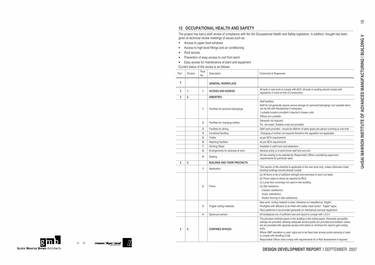
12 OCCUPATIONAL HEALTH AND SAFETY The project has had a draft review of compliance with the SA Occupational Health and Safety legislation. In addition, thought has been given at technical review meetings of issues such as: • Access to upper level windows • Access to high-level fittings and air conditioning • Roof access • Prevention of easy access to roof from berm • Easy access for maintenance of plant and equipment Current status of the review is as follows:
Part Division Para No
Description Comments & Responses
2 GENERAL WORKPLACE
2 1. 1 ACCESS AND EGRESS All exits in new work to comply with BCA. All exits in existing should comply with regulations in force at time of construction.
2 2. AMENITIES
1 Facilities for personal belongings
Staff facilities: Staff do not generally require secure storage for personal belongings, but valuable items can be left with Receptionist if necessary. Lockable location provided in teacher’s drawer units Offices are Lockable
2 Facilities for changing clothes Generally not required. For lab areas: Suitable coats are provided.
3 Facilities for dining Staff room provided - should be 600mm of table space per person lunching at one time 4 Combined facilities Changing of clothes not required therefore this regulation not applicable 5 Toilets as per BCA requirements 6 Washing Facilities As per BCA requirements 7 Drinking Water Available in staff room and elsewhere 8 Arrangements for sickness at work General policy is to send home staff who are sick
9 Seating All new seating to be selected by Responsible Officer considering ergonomic requirements for particular tasks
2 3. BUILDING AND THEIR PRECINCTS
1 Application This section of the checklist is applicable to the new work only, unless otherwise noted. Existing buildings should already comply.
2 Floors
(a) All floors to be of sufficient strength and evenness to carry out tasks. (b) Floors slope to drains as required by BCA. (c) Loose floor coverings not used in new building. (d) Slip resistance: Carpets: satisfactory Vinyls: satisfactory Rubber flooring to labs satisfactory
3 Fragile roofing materials New work: roofing material is steel, therefore not classified as "fragile". Rooflights with diffusers to be fitted with safety mesh and/or "fragile" signs. Plant platforms to be provided generally for mechanical services equipment.
4 Space per person All workplaces are of sufficient size and layout to comply with r.2.3.4
2 4. CONFINED SPACES
The principal confined space in this building is the ceiling space. Generally accessible ceilings are provided, allowing adequate access points are provided and isolation valves etc are provided with separate access from below to minimise the need to gain ceiling entry. Where SMF insulation is used, signs are to be fixed near access points advising of need to comply with handling Code. Responsible Officer shall comply with requirements for a Risk Assessment if required.
DESIGN DEVELOPMENT REPORT | SEPTEMBER 2007
UniS
A| M
AWSO
N IN
STIT
UTE
OF A
DVAN
CED
MAN
UFAC
TURI
NG |
BUIL
DING
V
17
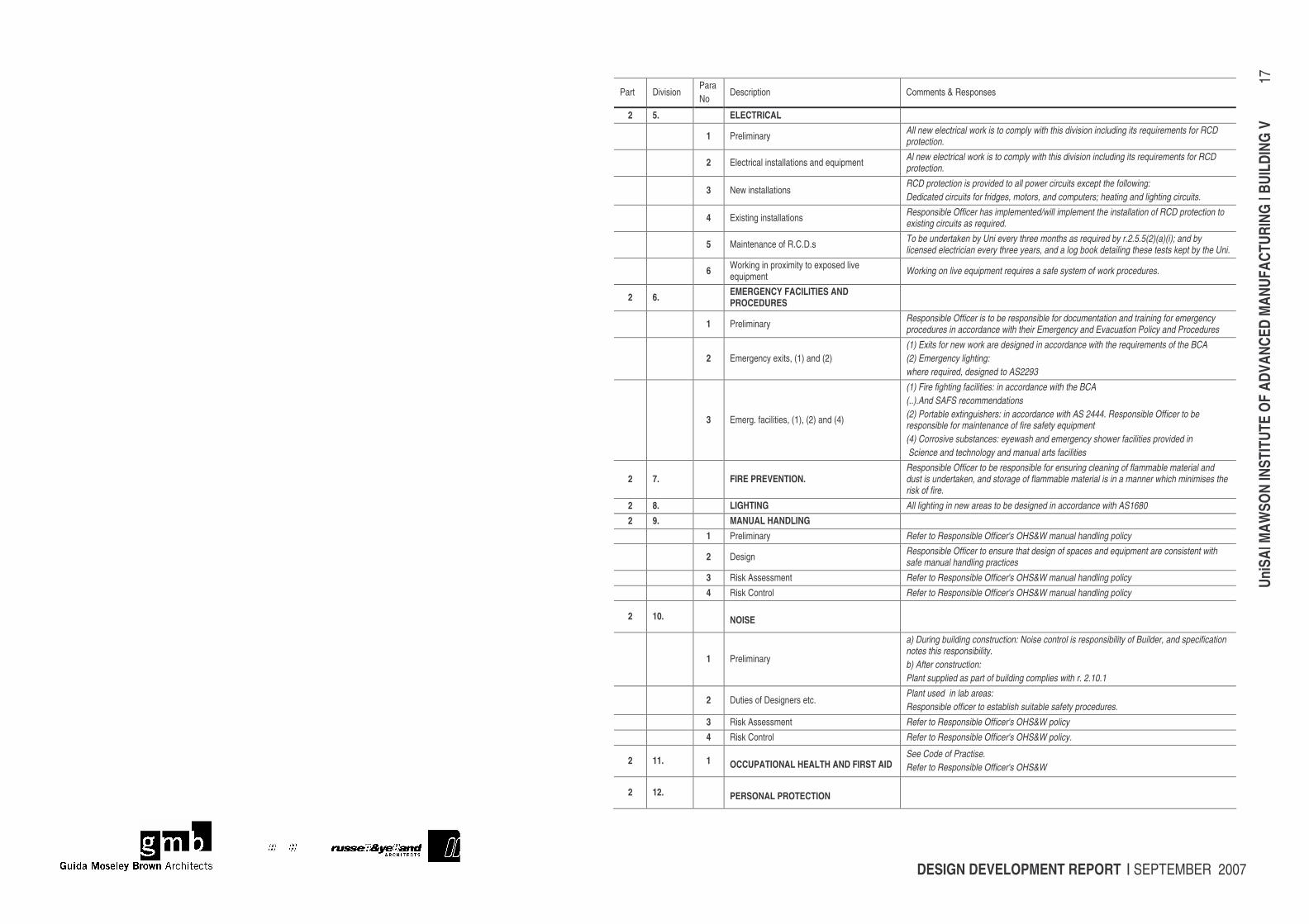
Part Division Para No
Description Comments & Responses
2 5. ELECTRICAL
1 Preliminary All new electrical work is to comply with this division including its requirements for RCD protection.
2 Electrical installations and equipment Al new electrical work is to comply with this division including its requirements for RCD protection.
3 New installations RCD protection is provided to all power circuits except the following: Dedicated circuits for fridges, motors, and computers; heating and lighting circuits.
4 Existing installations Responsible Officer has implemented/will implement the installation of RCD protection to existing circuits as required.
5 Maintenance of R.C.D.s To be undertaken by Uni every three months as required by r.2.5.5(2)(a)(i); and by licensed electrician every three years, and a log book detailing these tests kept by the Uni.
6 Working in proximity to exposed live equipment Working on live equipment requires a safe system of work procedures.
2 6. EMERGENCY FACILITIES AND PROCEDURES
1 Preliminary Responsible Officer is to be responsible for documentation and training for emergency procedures in accordance with their Emergency and Evacuation Policy and Procedures
2 Emergency exits, (1) and (2) (1) Exits for new work are designed in accordance with the requirements of the BCA (2) Emergency lighting: where required, designed to AS2293
3 Emerg. facilities, (1), (2) and (4)
(1) Fire fighting facilities: in accordance with the BCA (..).And SAFS recommendations (2) Portable extinguishers: in accordance with AS 2444. Responsible Officer to be responsible for maintenance of fire safety equipment (4) Corrosive substances: eyewash and emergency shower facilities provided in Science and technology and manual arts facilities
2 7. FIRE PREVENTION. Responsible Officer to be responsible for ensuring cleaning of flammable material and dust is undertaken, and storage of flammable material is in a manner which minimises the risk of fire.
2 8. LIGHTING All lighting in new areas to be designed in accordance with AS1680 2 9. MANUAL HANDLING 1 Preliminary Refer to Responsible Officer's OHS&W manual handling policy
2 Design Responsible Officer to ensure that design of spaces and equipment are consistent with safe manual handling practices
3 Risk Assessment Refer to Responsible Officer's OHS&W manual handling policy 4 Risk Control Refer to Responsible Officer's OHS&W manual handling policy
2 10. NOISE
1 Preliminary
a) During building construction: Noise control is responsibility of Builder, and specification notes this responsibility. b) After construction: Plant supplied as part of building complies with r. 2.10.1
2 Duties of Designers etc. Plant used in lab areas: Responsible officer to establish suitable safety procedures.
3 Risk Assessment Refer to Responsible Officer's OHS&W policy 4 Risk Control Refer to Responsible Officer's OHS&W policy.
2 11. 1 OCCUPATIONAL HEALTH AND FIRST AID See Code of Practise. Refer to Responsible Officer's OHS&W
2 12. PERSONAL PROTECTION
DESIGN DEVELOPMENT REPORT | SEPTEMBER 2007
UniS
A| M
AWSO
N IN
STIT
UTE
OF A
DVAN
CED
MAN
UFAC
TURI
NG |
BUIL
DING
V
18
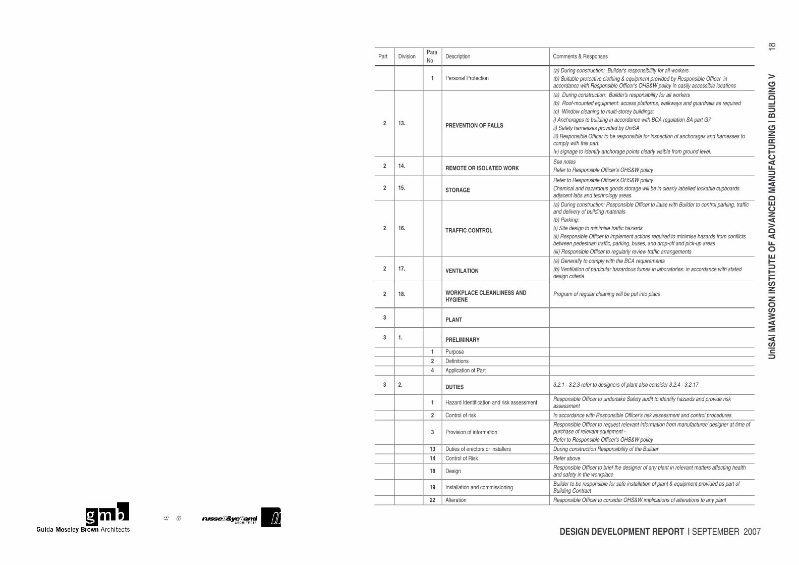
Part Division Para No
Description Comments & Responses
1 Personal Protection (a) During construction: Builder's responsibility for all workers (b) Suitable protective clothing & equipment provided by Responsible Officer in accordance with Responsible Officer's OHS&W policy in easily accessible locations
2 13. PREVENTION OF FALLS
(a) During construction: Builder's responsibility for all workers (b) Roof-mounted equipment: access platforms, walkways and guardrails as required (c) Window cleaning to multi-storey buildings: i) Anchorages to building in accordance with BCA regulation SA part G7 ii) Safety harnesses provided by UniSA iii) Responsible Officer to be responsible for inspection of anchorages and harnesses to comply with this part. Iv) signage to identify anchorage points clearly visible from ground level.
2 14. REMOTE OR ISOLATED WORK See notes Refer to Responsible Officer's OHS&W policy
2 15. STORAGE
Refer to Responsible Officer's OHS&W policy Chemical and hazardous goods storage will be in clearly labelled lockable cupboards adjacent labs and technology areas.
2 16. TRAFFIC CONTROL
(a) During construction: Responsible Officer to liaise with Builder to control parking, traffic and delivery of building materials (b) Parking: (i) Site design to minimise traffic hazards (ii) Responsible Officer to implement actions required to minimise hazards from conflicts between pedestrian traffic, parking, buses, and drop-off and pick-up areas (iii) Responsible Officer to regularly review traffic arrangements
2 17. VENTILATION
(a) Generally to comply with the BCA requirements (b) Ventilation of particular hazardous fumes in laboratories: in accordance with stated design criteria
2 18. WORKPLACE CLEANLINESS AND HYGIENE
Program of regular cleaning will be put into place
3 PLANT
3 1. PRELIMINARY
1 Purpose 2 Definitions 4 Application of Part
3 2. DUTIES 3.2.1 - 3.2.3 refer to designers of plant also consider 3.2.4 - 3.2.17
1 Hazard Identification and risk assessment Responsible Officer to undertake Safety audit to identify hazards and provide risk assessment
2 Control of risk In accordance with Responsible Officer's risk assessment and control procedures
3 Provision of information Responsible Officer to request relevant information from manufacturer/ designer at time of purchase of relevant equipment - Refer to Responsible Officer's OHS&W policy
13 Duties of erectors or installers During construction Responsibility of the Builder 14 Control of Risk Refer above
18 Design Responsible Officer to brief the designer of any plant in relevant matters affecting health and safety in the workplace
19 Installation and commissioning Builder to be responsible for safe installation of plant & equipment provided as part of Building Contract
22 Alteration Responsible Officer to consider OHS&W implications of alterations to any plant
DESIGN DEVELOPMENT REPORT | SEPTEMBER 2007
UniS
A| M
AWSO
N IN
STIT
UTE
OF A
DVAN
CED
MAN
UFAC
TURI
NG |
BUIL
DING
V
19
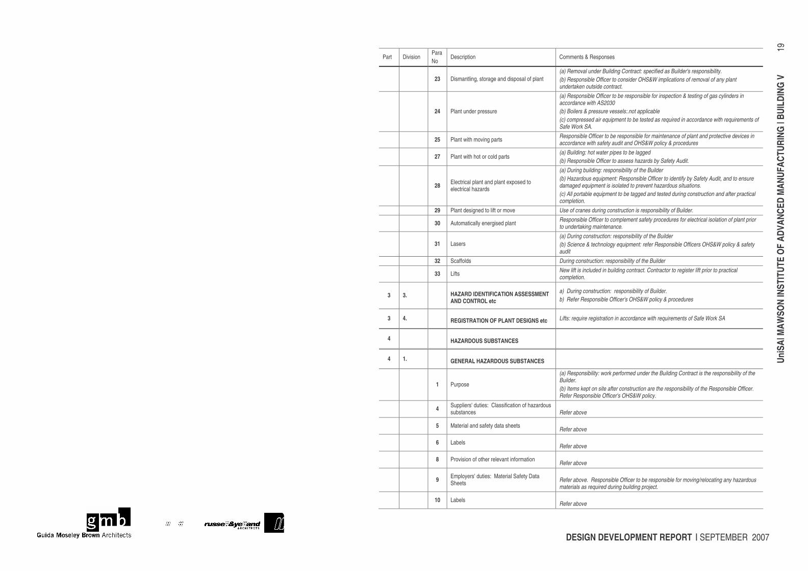
Part Division Para No
Description Comments & Responses
23 Dismantling, storage and disposal of plant (a) Removal under Building Contract: specified as Builder's responsibility. (b) Responsible Officer to consider OHS&W implications of removal of any plant undertaken outside contract.
24 Plant under pressure
(a) Responsible Officer to be responsible for inspection & testing of gas cylinders in accordance with AS2030 (b) Boilers & pressure vessels:.not applicable (c) compressed air equipment to be tested as required in accordance with requirements of Safe Work SA.
25 Plant with moving parts Responsible Officer to be responsible for maintenance of plant and protective devices in accordance with safety audit and OHS&W policy & procedures
27 Plant with hot or cold parts (a) Building: hot water pipes to be lagged (b) Responsible Officer to assess hazards by Safety Audit.
28 Electrical plant and plant exposed to electrical hazards
(a) During building: responsibility of the Builder (b) Hazardous equipment: Responsible Officer to identify by Safety Audit, and to ensure damaged equipment is isolated to prevent hazardous situations. (c) All portable equipment to be tagged and tested during construction and after practical completion.
29 Plant designed to lift or move Use of cranes during construction is responsibility of Builder.
30 Automatically energised plant Responsible Officer to complement safety procedures for electrical isolation of plant prior to undertaking maintenance.
31 Lasers (a) During construction: responsibility of the Builder (b) Science & technology equipment: refer Responsible Officers OHS&W policy & safety audit
32 Scaffolds During construction: responsibility of the Builder
33 Lifts New lift is included in building contract. Contractor to register lift prior to practical completion.
3 3. HAZARD IDENTIFICATION ASSESSMENT AND CONTROL etc
a) During construction: responsibility of Builder. b) Refer Responsible Officer's OHS&W policy & procedures
3 4. REGISTRATION OF PLANT DESIGNS etc Lifts: require registration in accordance with requirements of Safe Work SA
4 HAZARDOUS SUBSTANCES
4 1. GENERAL HAZARDOUS SUBSTANCES
1 Purpose
(a) Responsibility: work performed under the Building Contract is the responsibility of the Builder. (b) Items kept on site after construction are the responsibility of the Responsible Officer. Refer Responsible Officer's OHS&W policy.
4 Suppliers' duties: Classification of hazardous substances Refer above
5 Material and safety data sheets Refer above
6 Labels Refer above
8 Provision of other relevant information Refer above
9 Employers' duties: Material Safety Data Sheets Refer above. Responsible Officer to be responsible for moving/relocating any hazardous
materials as required during building project.
10 Labels Refer above
DESIGN DEVELOPMENT REPORT | SEPTEMBER 2007
UniS
A| M
AWSO
N IN
STIT
UTE
OF A
DVAN
CED
MAN
UFAC
TURI
NG |
BUIL
DING
V
20
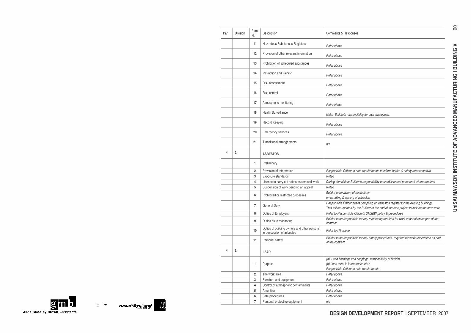
Part Division Para No
Description Comments & Responses
11 Hazardous Substances Registers Refer above
12 Provision of other relevant information Refer above
13 Prohibition of scheduled substances Refer above
14 Instruction and training Refer above
15 Risk assessment Refer above
16 Risk control Refer above
17 Atmospheric monitoring Refer above
18 Health Surveillance Note: Builder's responsibility for own employees.
19 Record Keeping Refer above
20 Emergency services Refer above
21 Transitional arrangements n/a
4 2. ASBESTOS
1 Preliminary 2 Provision of Information Responsible Officer to note requirements to inform health & safety representative 3 Exposure standards Noted 4 Licence to carry out asbestos removal work During demolition: Builder's responsibility to used licensed personnel where required 5 Suspension of work pending an appeal Noted
6 Prohibited or restricted processes Builder to be aware of restrictions on handling & sealing of asbestos
7 General Duty Responsible Officer has/is compiling an asbestos register for the existing buildings. This will be updated by the Builder at the end of the new project to include the new work.
8 Duties of Employers Refer to Responsible Officer's OHS&W policy & procedures
9 Duties as to monitoring Builder to be responsible for any monitoring required for work undertaken as part of the contract.
10 Duties of building owners and other persons in possession of asbestos Refer to (7) above
11 Personal safety Builder to be responsible for any safety procedures required for work undertaken as part of the contract.
4 3. LEAD
1 Purpose (a) Lead flashings and cappings: responsibility of Builder. (b) Lead used in laboratories etc.: Responsible Officer to note requirements
2 The work area Refer above 3 Furniture and equipment Refer above
4 Control of atmospheric contaminants Refer above 5 Amenities Refer above 6 Safe procedures Refer above 7 Personal protective equipment n/a
DESIGN DEVELOPMENT REPORT | SEPTEMBER 2007
UniS
A| M
AWSO
N IN
STIT
UTE
OF A
DVAN
CED
MAN
UFAC
TURI
NG |
BUIL
DING
V
21
Part Division Para No
Description Comments & Responses
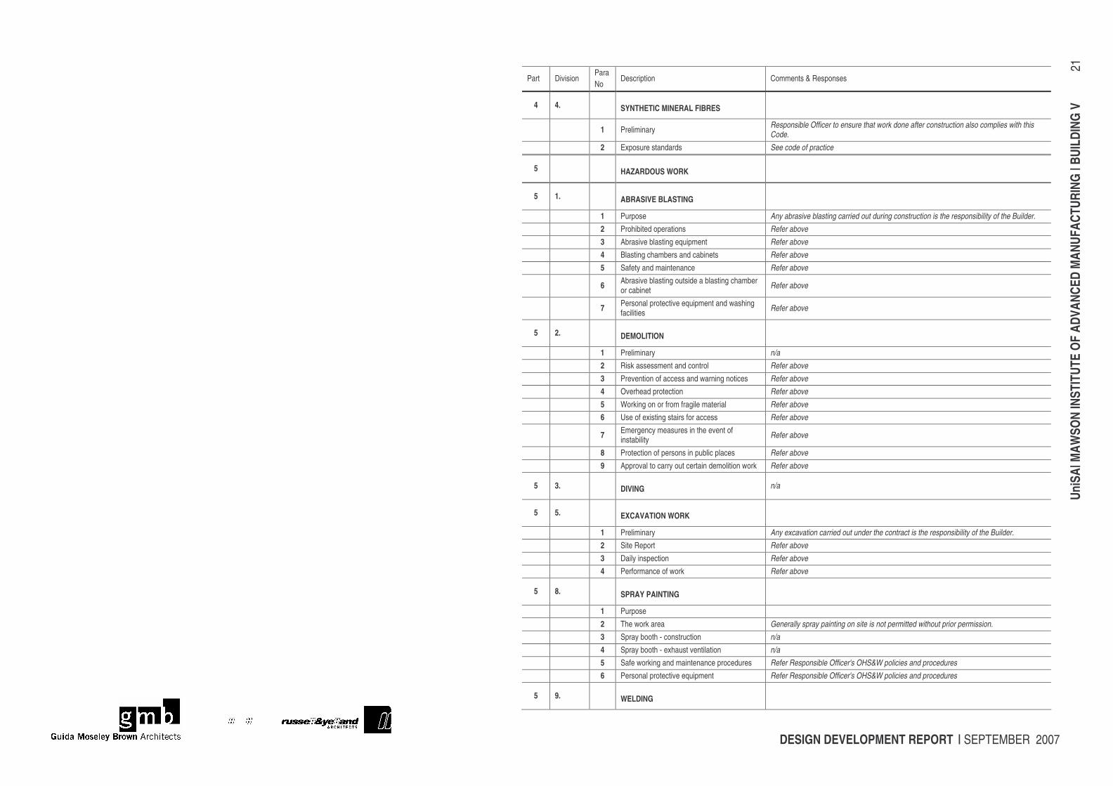
4 4. SYNTHETIC MINERAL FIBRES
1 Preliminary Responsible Officer to ensure that work done after construction also complies with this Code.
2 Exposure standards See code of practice
5 HAZARDOUS WORK
5 1. ABRASIVE BLASTING
1 Purpose Any abrasive blasting carried out during construction is the responsibility of the Builder. 2 Prohibited operations Refer above 3 Abrasive blasting equipment Refer above 4 Blasting chambers and cabinets Refer above 5 Safety and maintenance Refer above
6 Abrasive blasting outside a blasting chamber or cabinet Refer above
7 Personal protective equipment and washing facilities Refer above
5 2. DEMOLITION
1 Preliminary n/a 2 Risk assessment and control Refer above 3 Prevention of access and warning notices Refer above 4 Overhead protection Refer above 5 Working on or from fragile material Refer above 6 Use of existing stairs for access Refer above
7 Emergency measures in the event of instability Refer above
8 Protection of persons in public places Refer above 9 Approval to carry out certain demolition work Refer above
5 3. DIVING n/a
5 5. EXCAVATION WORK
1 Preliminary Any excavation carried out under the contract is the responsibility of the Builder. 2 Site Report Refer above 3 Daily inspection Refer above 4 Performance of work Refer above
5 8. SPRAY PAINTING
1 Purpose 2 The work area Generally spray painting on site is not permitted without prior permission. 3 Spray booth - construction n/a 4 Spray booth - exhaust ventilation n/a 5 Safe working and maintenance procedures Refer Responsible Officer's OHS&W policies and procedures 6 Personal protective equipment Refer Responsible Officer's OHS&W policies and procedures
5 9. WELDING
DESIGN DEVELOPMENT REPORT | SEPTEMBER 2007
UniS
A| M
AWSO
N IN
STIT
UTE
OF A
DVAN
CED
MAN
UFAC
TURI
NG |
BUIL
DING
V
22
Part Division Para No
Description Comments & Responses
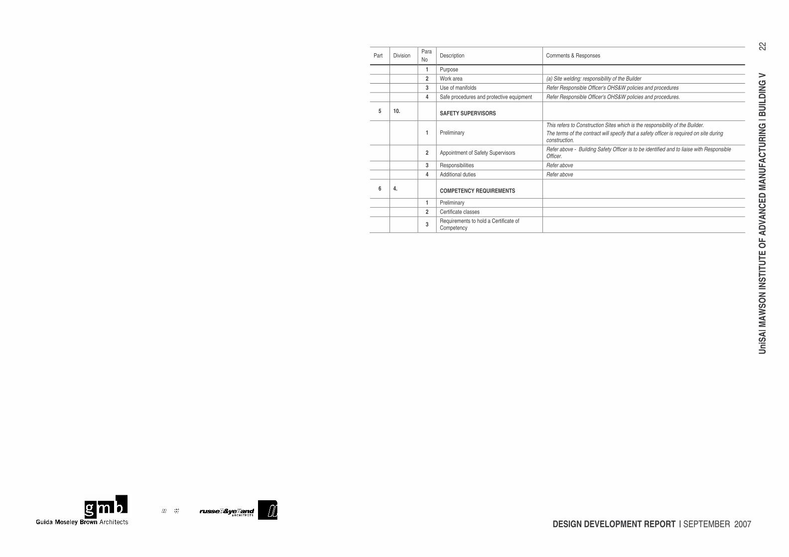
1 Purpose 2 Work area (a) Site welding: responsibility of the Builder 3 Use of manifolds Refer Responsible Officer's OHS&W policies and procedures 4 Safe procedures and protective equipment Refer Responsible Officer's OHS&W policies and procedures.
5 10. SAFETY SUPERVISORS
1 Preliminary This refers to Construction Sites which is the responsibility of the Builder. The terms of the contract will specify that a safety officer is required on site during construction.
2 Appointment of Safety Supervisors Refer above - Building Safety Officer is to be identified and to liaise with Responsible Officer.
3 Responsibilities Refer above 4 Additional duties Refer above
6 4. COMPETENCY REQUIREMENTS
1 Preliminary 2 Certificate classes
3 Requirements to hold a Certificate of Competency
DESIGN DEVELOPMENT REPORT | SEPTEMBER 2007
UniS
A| M
AWSO
N IN
STIT
UTE
OF A
DVAN
CED
MAN
UFAC
TURI
NG |
BUIL
DING
V
23
13 DISABILITY ACCESS Becky Llewellyn of DCS met with John Held, Kobus Pienaar, Dominic Marafioti, Justene Knight and David Knight on August 14th 2007 to review disability requirements of the MIAM project. The design team at Guida Moseley Brown & Russell & Yelland has been mindful of all the disability codes in planning the building exterior and interior in the following areas: External Access The building on the Mawson Lakes campus takes advantage of the flat terrain which makes access much easier. Discussion of a possible walking trail around the swale centred on some of the access difficulties of the deck’s height and function. The walking trail will be considered later as part of a wider UniSA landscaping program. Carparking There is already adequate carparking in the vicinity of the new MIAM facility, but one more will be added adjacent the building. Ground and pole-mark a complying disability wide-bay carpark at the bay nearest the main entry. Continuous Accessible Pathway - The design creates a continuous accessible pathway and flow throughout the whole building. The main entry and deck entry have level thresholds. Floors have level surfaces throughout, with the exception of the Clean Room which I will address separately. The double doorways all have a single leaf with at least 860mm clear width allowing independent mobility for wheelchair users. The deck has railings and kerb rails for safety of mobility aid users. Stairs Stairs meet AS1428.1 requirements for handrails, tactiles and nosings. Lift The lift to the Mezzanine level complies with disability requirements of AS1735.12. Sanitary Facilities There are two Access Toilets on the ground floor, one accessible to the public attending functions in the Large Meeting Room. Two suggestions to improve the plan are: The toilet pan position are handed so that they can cater for left and right handed transfers and sign accordingly with the universal symbol turned in the direction of transfer. An audible/visual emergency alarm will be provided in theses toilets for a user who may have severe hearing impairment. Emergency Evacuation The upper mezzanine floor has a large fire refuge space at the top of the staircase which needs to be included on building evacuation plans. UniSA is considering standardising marking of these safe havens. Until a standard is set, paint a small disability parking bay symbol on floor 900 x 1300mm and a sign outside the door with the universal wheelchair symbol and “Fire Refuge”. Add a 600mm grabrail as per AS1735.12 for people with ambulant disability. Consider installing a form of warden intercom to the ground level for emergency personnel to be in contact with users of the refuge. Controls and Switches To aid in building continuity, all controls will be set at 1000mm and back at least 500mm from corners. Hearing Loop Hearing augmentation will be provided for the meeting room. In keeping with UniSA policy, install a hearing loop in the Large Meeting Room as the preferred form of hearing augmentation provision. Signage Signage of lift and toilets will include symbol signage and where appropriate, raised tactile and braille information. The preferred location of the toilet signs is on the wall 100mm from the frame of the door, 1200 1600mm height range. This means that a visually impaired person cannot be hit by a door swinging while they are trying to feel the symbol. Clean Room After much discussion of design possibilities and limitations over several meetings, Russell & Yelland and DCS have not found an answer to how to make the sterile Clean Room accessible to a mobility aid user. Currently there are no codes to assist in this. Given this context, the group agreed to take the approach of treating the Clean Room as an area that is not fully required to be accessible at this time.
DESIGN DEVELOPMENT REPORT | SEPTEMBER 2007
UniS
A| M
AWSO
N IN
STIT
UTE
OF A
DVAN
CED
MAN
UFAC
TURI
NG |
BUIL
DING
V
24
If there were to be a Clean Room user who had a major disability, the University management could meet that challenge by creating a ‘reasonable adjustment’ under the DDA, working in conjunction with that person to tailor a design solution with them to meet their particular needs. This practice has also been adopted by UniSA in the recent CERAR project and was noted by Justene Knight, Senior Consultant: Equity, Diversity and Workplace Relations, who has responsibility for staff on the UniSA campuses. Reception Fixed reception desk will include an area at an accessible height. Consideration could also be given to installing deafness friendly microphone/receiver equipment such as that offered by DeafSA consultant, Rod McGinniss. Summary The Draft DDA Access to Premises Standard was released for consultation in February 2004 and has yet to be incorporated in Commonwealth legislation. Although the advice presented by DCS is in accordance with current best practice and Australian Standards regarding access, no guarantees can be given by DCS against future claims under the DDA, as there is no legal Standard yet endorsed, by the authorities This building will incorporate many new innovations emanating from the fields of energy, environment and ageing, which is the growing demographic of disability. The provisions included meet the needs of building users into the future and allow a flexible, safe workplace for creativity to flourish across and within these disciplines.
DESIGN DEVELOPMENT REPORT | SEPTEMBER 2007
UniS
A| M
AWSO
N IN
STIT
UTE
OF A
DVAN
CED
MAN
UFAC
TURI
NG |
BUIL
DING
V
25
14 ENGINEERING SERVICES
14.1 INTRODUCTION The building services will be developed in line with the University of South Australia Design and Construction Guidelines – Section 11 Engineering Services. These guidelines set out design criteria, standardisation, installation requirements etc. The Services fit-out for the MIAM Building will address the requirements (quantities, layouts etc) obtained via Design Team consultation with the user group. These details are to be collated in the form of room data sheets/1:50 architectural plans and will be addressed further in the detailed design phase.
14.2 FIRE PROTECTION SERVICES • Existing fire main to be extended to serve external fire hydrants, internal fire hose reels and sprinkler system. • Sprinkler valve room to be located at the North West corner of the building. Provision of two (2) distinct distribution mains to monitor
the Administration areas independently from the laboratory areas. • “Partial layout” fire alarm detection system (early warning smoke detectors) including some manual call points to be provided. These
will be connected to a sub Fire Indicator Panel (FIP) located in the Sprinkler Valve Room (to suit SAMFS requirements). • Sub FIP to be connected to the UniSA Mawson Lakes Campus master FIP (Building A) and provided with a new Alarm Transmission
Unit (ATU), as requested by UniSA. • An Emergency Warning and Intercommunication System (EWIS) will be provided, as requested by UniSA. • Portable fire extinguishers to be located throughout the building • In the event of a fire being detected, an alarm condition will be derived to evacuate building personnel, transmit an alarm to the
SAMFS and UniSA security personnel, and activate air conditioning systems to shut down (for the zone in alarm).
14.3 MECHANICAL SERVICES • Chilled and heating water pipework to be extended from the services tunnel (as close as possible to the Power House) to provide
thermal cooling and heating water for the new air conditioning systems. • Thermal water supplies will be metered and pumped from a plantroom at the North West corner of the building (high level metering
interface with BMS) • Chilled and heating water will be reticulated to air handling plant, active chilled beam units, fan coil units, etc to suit the Administration
and Laboratory areas. • A Universal Network Controller (UNC) will be provided in the North West plantroom and will be connected to the site Building
Management System (BMS) via conduits in the services tunnel. The UNC will control the airconditioning and ventilation plant and will be capable of providing scheduling and status/alarm functions.
• Four (4) proprietary variable air volume fume cupboards and one constant volume fume exhaust hood (over decanting sink within Store area) will be provided. Each fume exhaust fan will be located at high level in the peristial space and flues will extend vertically above the roof (height of termination will be between 3 and 5m, depending on EPA requirements).
• Each Laboratory air handling unit supply air fan will be equipped with a Variable Speed Drive (VSD) to vary the overall supply air volume in response to thermal loads. Motorised outside air dampers will be interlocked with the fume cupboards and C02 sensors (outside air volume will vary in response to C02 levels and fume extraction make up air requirements.
• The Visualisation Lab Computer room will be equipped with a close control type air conditioning unit, specifically designed for equipment/process cooling applications). Conditioned air will be discharged under the raised floor and will be dispersed through the room via floor grilles.
• Economy Cycle systems (free cooling via outside air) systems will be considered for the Laboratory area air handling units. Under Economy Cycle mode, Outside Air will be used to provide space cooling (with no additional heating/cooling from thermal water supplies) when ambient conditions permit.
• Laboratory gases required for various points of service (Laboratory benches) will be sourced from gas storage cylinders located in the peristitial space. Flammable and non-flammable gases will be separated in accordance with the relevant code requirements. At present, Natural gas is not envisaged to be provided (to be confirmed by the University)
DESIGN DEVELOPMENT REPORT | SEPTEMBER 2007
UniS
A| M
AWSO
N IN
STIT
UTE
OF A
DVAN
CED
MAN
UFAC
TURI
NG |
BUIL
DING
V
26
• Cleanrooms (Cell Culture Lab areas) will be conditioned via independent air handling units incorporating appropriate High Efficiency Particulate Air Filters (HEPA), controls, pressurisation etc to meet Class 10000 (SI 350) generally within the rooms. Proprietary Laminar Flow cupboards will be provided to achieve Class 1000 (SI 35) where required.
• Ducted Exhaust ventilation systems will be provided to the toilets, kitchen and Laboratory Store areas, in accordance with AS 1668.2 requirements.
• The Laboratory Store will have a separate air handling unit to provide exhaust make-up air and tempered cooling conditions only (a general exhaust system will be provided to extract heat from vacuum pumps and lab chillers etc which are to be provided by Uni SA).
14.4 VERTICAL TRANSPORTATION SERVICES • An eight (8) passenger (630kg) machine room less lift will be provided and will be equipped for persons with limited mobility (to
comply with AS 1735.12). Approximate internal dimensions of the lift will be 1100mm (W) X 1400mm (D). The lift will be fitted with through-car openings and standard finishes.
14.5 HYDRAULIC SERVICES • Potable water mains and recycled water mains to be extended from existing site services • Metering to be provided for each service with pulse outflow and high level interface with BMS for monitoring • Backflow prevention assemblies to be provided in accordance with code and regulatory authority requirements • Hot Water to be provided by way of roof mounted solar collectors with gas fired Hot Water Services as backup/boost. Independent
supplies (2-off) to be provided for Laboratory and Administration areas. • Sewer main to be extended from existing main located adjacent to and parallel with services tunnel • Trade waste pits to be provided in laboratories (North side) • Sanitary plumbing fixtures and fittings to be provided in accordance with the Australian Government Water Efficiency Labelling and
Standards Scheme (WELS). • Laboratory fixtures and fittings, types to be coordinated with end users. • Laboratory emergency eye /face wash facilities and showers to be provided, where required. • Hands-free basins to be provided in laboratories
14.6 ELECTRICAL SERVICES • Power to be reticulated from ‘Power House’ building via underground conduits adjacent service conduit. • MIAM building main switchboard to be located in the services area on the western end of the building. • Diesel backup generator to be located external to the building, providing emergency electrical supply. • UPS requirements to be discussed as function of each space is confirmed. • Individual distribution boards for each laboratory to be located within the peristitial space. • Multifunction meters to be located in each distribution board with high level interface to BMS for monitoring. • Power for benches within Laboratories to be reticulated from peristitial space, through benches to bench mounted bollards. • Lighting to Laboratories to be supplied by suspended fluorescent luminaries with up and down component, to 600/800 lux as
requested. • Lighting to open office area to be provided as a two component system with general light to 200 lux, with workstation mounted task
lighting to provide additional desk light as required. • Motion sensors to be installed within offices, small meeting rooms and other associated small closed areas to control lighting, with
adjustable timed off. • Power and data to open office area to be reticulated via a grid of recessed floor boxes to allow maximum flexibility for future layouts. • Exit and emergency lighting to be provided in accordance with AS 2293. Central monitoring of emergency fittings to be provided via
Stanilite Nexus LX computer monitoring system, and interfaced to existing site monitoring system. • External amenity and security lighting to be discussed further with Architect and UniSA. • C-bus lighting control to be provided to Meeting Room and Visualisation Lab (incorporate AMX control system via high level interface). • Audio visual provisions to be incorporated in accordance with AV Consultant’s requirements.
DESIGN DEVELOPMENT REPORT | SEPTEMBER 2007
UniS
A| M
AWSO
N IN
STIT
UTE
OF A
DVAN
CED
MAN
UFAC
TURI
NG |
BUIL
DING
V
27
14.7 COMMUNICATION SERVICES • Fibre optic backbone to be provided as 12pr zero water peak single mode fibre optic in each direction (Twenty-Four (24) total) from
main services tunnel fibre ring and reticulated to MIAM building via underground conduit adjacent services culvert. • 100pr voice backbone cable to be provided from MDF / PABX room within the administration building, to MIAM building via main
services tunnel and underground conduits. • Two (2) communications cabinets located in the north west, and south east of the building to house active equipment, fibre and voice
services. • 50pr voice connections to be provided to each cabinet. • Horizontal cabling to be Category 6.
14.8 SECURITY • Electronic Access Control has been indicatively shown on drawings. Further discussion with UniSA required to confirm operation and
access control strategy for each door. • Intruder detection including passive infrared detectors, glass break sensors and door monitoring to be discussed further with UniSA. • Security backbone cabling provided to interface MIAM building with existing site security system.
14.9 MAINTENANCE ISSUES • At this stage, serviceable equipment located at high level within the Administration and Visualisation Lab areas (active chilled beam
units, air distribution volume control dampers, lighting, smoke/thermal detectors, fire sprinklers etc) will require access via a proprietary mobile platform (to be confirmed by Uni SA).
• Fume cupboard and other toxic/irritant exhaust discharges at roof level may present exposure hazards to maintenance personnel. Risks to be mitigated via minimisation of roof mounted equipment requiring maintenance (no roof mounted air conditioning plant etc), careful location of hazardous discharges and possible alarm devices indicating the presence of personnel at roof level (strategies to be investigated further in conjunction with Uni SA).
• Maintenance of fume cupboard exhaust fans and fan coil units located at high level within the peristitial space will require access via a suitable ladder or mobile platform.
• Ceiling access panels will be required to service plant items installed above flush mounted ceilings or bulkheads.
DESIGN DEVELOPMENT REPORT | SEPTEMBER 2007
UniS
A| M
AWSO
N IN
STIT
UTE
OF A
DVAN
CED
MAN
UFAC
TURI
NG |
BUIL
DING
V
28
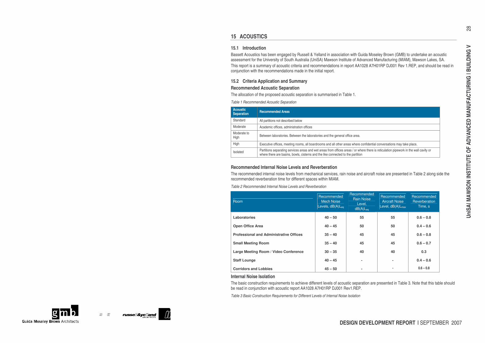
15 ACOUSTICS
15.1 Introduction Bassett Acoustics has been engaged by Russell & Yelland in association with Guida Moseley Brown (GMB) to undertake an acoustic assessment for the University of South Australia (UniSA) Mawson Institute of Advanced Manufacturing (MIAM), Mawson Lakes, SA. This report is a summary of acoustic criteria and recommendations in report AA1028 A7H01RP DJ001 Rev 1.REP, and should be read in conjunction with the recommendations made in the initial report.
15.2 Criteria Application and Summary Recommended Acoustic Separation The allocation of the proposed acoustic separation is summarised in Table 1.
Table 1 Recommended Acoustic Separation
Acoustic Separation Recommended Areas
Standard All partitions not described below
Moderate Academic offices, administration offices
Moderate to High Between laboratories. Between the laboratories and the general office area.
High Executive offices, meeting rooms, all boardrooms and all other areas where confidential conversations may take place.
Isolated Partitions separating services areas and wet areas from offices areas / or where there is reticulation pipework in the wall cavity or where there are basins, bowls, cisterns and the like connected to the partition
Recommended Internal Noise Levels and Reverberation The recommended internal noise levels from mechanical services, rain noise and aircraft noise are presented in Table 2 along side the recommended reverberation time for different spaces within MIAM.
Table 2 Recommended Internal Noise Levels and Reverberation
Room Recommended
Mech Noise Levels, dB(A)Leq
Recommended Rain Noise
Level, dB(A)Leq
Recommended Aircraft Noise
Level, dB(A)Lmax
Recommended Reverberation
Time, s
Laboratories 40 – 50 55 55 0.6 – 0.8
Open Office Area 40 – 45 50 50 0.4 – 0.6
Professional and Administrative Offices 35 – 40 45 45 0.6 – 0.8
Small Meeting Room 35 – 40 45 45 0.6 – 0.7
Large Meeting Room / Video Conference 30 – 35 40 40 0.3
Staff Lounge 40 – 45 - - 0.4 – 0.6
Corridors and Lobbies 45 – 50 - - 0.6 – 0.8
Internal Noise Isolation The basic construction requirements to achieve different levels of acoustic separation are presented in Table 3. Note that this table should be read in conjunction with acoustic report AA1028 A7H01RP DJ001 Rev1.REP.
Table 3 Basic Construction Requirements for Different Levels of Internal Noise Isolation
DESIGN DEVELOPMENT REPORT | SEPTEMBER 2007
UniS
A| M
AWSO
N IN
STIT
UTE
OF A
DVAN
CED
MAN
UFAC
TURI
NG |
BUIL
DING
V
29
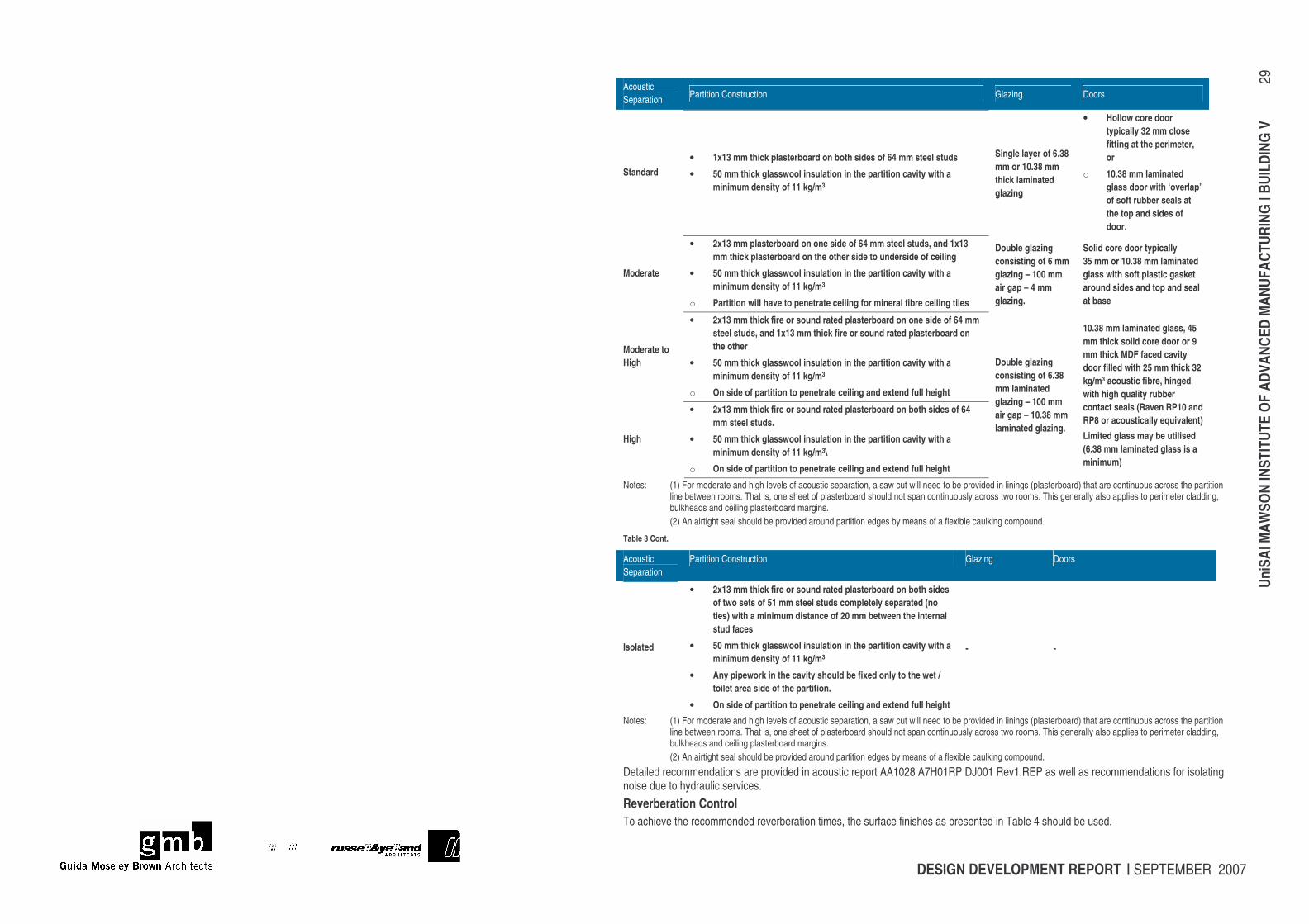
Acoustic Separation Partition Construction Glazing Doors
Standard • 1x13 mm thick plasterboard on both sides of 64 mm steel studs
• 50 mm thick glasswool insulation in the partition cavity with a minimum density of 11 kg/m3
Single layer of 6.38 mm or 10.38 mm thick laminated glazing
• Hollow core door typically 32 mm close fitting at the perimeter, or
o 10.38 mm laminated glass door with ‘overlap’ of soft rubber seals at the top and sides of door.
Moderate
• 2x13 mm plasterboard on one side of 64 mm steel studs, and 1x13 mm thick plasterboard on the other side to underside of ceiling
• 50 mm thick glasswool insulation in the partition cavity with a minimum density of 11 kg/m3
o Partition will have to penetrate ceiling for mineral fibre ceiling tiles
Double glazing
consisting of 6 mm glazing – 100 mm air gap – 4 mm glazing.
Solid core door typically 35 mm or 10.38 mm laminated glass with soft plastic gasket around sides and top and seal at base
Moderate to High
• 2x13 mm thick fire or sound rated plasterboard on one side of 64 mm steel studs, and 1x13 mm thick fire or sound rated plasterboard on the other
• 50 mm thick glasswool insulation in the partition cavity with a minimum density of 11 kg/m3
o On side of partition to penetrate ceiling and extend full height
High
• 2x13 mm thick fire or sound rated plasterboard on both sides of 64 mm steel studs.
• 50 mm thick glasswool insulation in the partition cavity with a minimum density of 11 kg/m3\
o On side of partition to penetrate ceiling and extend full height
Double glazing
consisting of 6.38 mm laminated glazing – 100 mm air gap – 10.38 mm laminated glazing.
10.38 mm laminated glass, 45 mm thick solid core door or 9 mm thick MDF faced cavity door filled with 25 mm thick 32 kg/m3 acoustic fibre, hinged with high quality rubber contact seals (Raven RP10 and RP8 or acoustically equivalent) Limited glass may be utilised (6.38 mm laminated glass is a minimum)
Notes: (1) For moderate and high levels of acoustic separation, a saw cut will need to be provided in linings (plasterboard) that are continuous across the partition line between rooms. That is, one sheet of plasterboard should not span continuously across two rooms. This generally also applies to perimeter cladding, bulkheads and ceiling plasterboard margins. (2) An airtight seal should be provided around partition edges by means of a flexible caulking compound.
Table 3 Cont.
Acoustic Separation
Partition Construction Glazing Doors
Isolated
• 2x13 mm thick fire or sound rated plasterboard on both sides of two sets of 51 mm steel studs completely separated (no ties) with a minimum distance of 20 mm between the internal stud faces
• 50 mm thick glasswool insulation in the partition cavity with a minimum density of 11 kg/m3
• Any pipework in the cavity should be fixed only to the wet / toilet area side of the partition.
• On side of partition to penetrate ceiling and extend full height
- -
Notes: (1) For moderate and high levels of acoustic separation, a saw cut will need to be provided in linings (plasterboard) that are continuous across the partition line between rooms. That is, one sheet of plasterboard should not span continuously across two rooms. This generally also applies to perimeter cladding, bulkheads and ceiling plasterboard margins. (2) An airtight seal should be provided around partition edges by means of a flexible caulking compound.
Detailed recommendations are provided in acoustic report AA1028 A7H01RP DJ001 Rev1.REP as well as recommendations for isolating noise due to hydraulic services. Reverberation Control To achieve the recommended reverberation times, the surface finishes as presented in Table 4 should be used.
DESIGN DEVELOPMENT REPORT | SEPTEMBER 2007
UniS
A| M
AWSO
N IN
STIT
UTE
OF A
DVAN
CED
MAN
UFAC
TURI
NG |
BUIL
DING
V
30
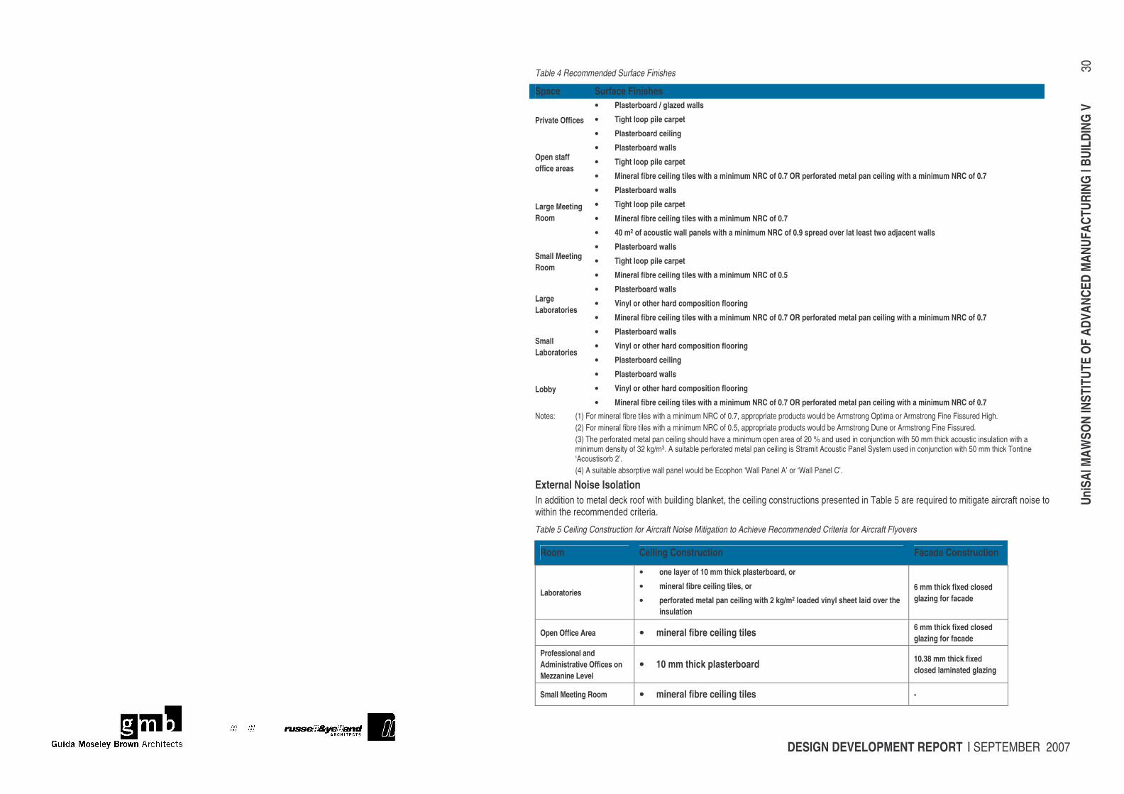
Table 4 Recommended Surface Finishes
Space Surface Finishes
Private Offices
• Plasterboard / glazed walls
• Tight loop pile carpet
• Plasterboard ceiling
Open staff office areas
• Plasterboard walls
• Tight loop pile carpet
• Mineral fibre ceiling tiles with a minimum NRC of 0.7 OR perforated metal pan ceiling with a minimum NRC of 0.7
Large Meeting Room
• Plasterboard walls
• Tight loop pile carpet
• Mineral fibre ceiling tiles with a minimum NRC of 0.7
• 40 m2 of acoustic wall panels with a minimum NRC of 0.9 spread over lat least two adjacent walls
Small Meeting Room
• Plasterboard walls
• Tight loop pile carpet
• Mineral fibre ceiling tiles with a minimum NRC of 0.5
Large Laboratories
• Plasterboard walls
• Vinyl or other hard composition flooring
• Mineral fibre ceiling tiles with a minimum NRC of 0.7 OR perforated metal pan ceiling with a minimum NRC of 0.7
Small Laboratories
• Plasterboard walls
• Vinyl or other hard composition flooring
• Plasterboard ceiling
Lobby
• Plasterboard walls
• Vinyl or other hard composition flooring
• Mineral fibre ceiling tiles with a minimum NRC of 0.7 OR perforated metal pan ceiling with a minimum NRC of 0.7 Notes: (1) For mineral fibre tiles with a minimum NRC of 0.7, appropriate products would be Armstrong Optima or Armstrong Fine Fissured High.
(2) For mineral fibre tiles with a minimum NRC of 0.5, appropriate products would be Armstrong Dune or Armstrong Fine Fissured. (3) The perforated metal pan ceiling should have a minimum open area of 20 % and used in conjunction with 50 mm thick acoustic insulation with a minimum density of 32 kg/m3. A suitable perforated metal pan ceiling is Stramit Acoustic Panel System used in conjunction with 50 mm thick Tontine ‘Acoustisorb 2’. (4) A suitable absorptive wall panel would be Ecophon ‘Wall Panel A’ or ‘Wall Panel C’.
External Noise Isolation In addition to metal deck roof with building blanket, the ceiling constructions presented in Table 5 are required to mitigate aircraft noise to within the recommended criteria.
Table 5 Ceiling Construction for Aircraft Noise Mitigation to Achieve Recommended Criteria for Aircraft Flyovers
Room Ceiling Construction Facade Construction
Laboratories
• one layer of 10 mm thick plasterboard, or
• mineral fibre ceiling tiles, or
• perforated metal pan ceiling with 2 kg/m2 loaded vinyl sheet laid over the insulation
6 mm thick fixed closed glazing for facade
Open Office Area • mineral fibre ceiling tiles 6 mm thick fixed closed glazing for facade
Professional and Administrative Offices on Mezzanine Level
• 10 mm thick plasterboard 10.38 mm thick fixed closed laminated glazing
Small Meeting Room • mineral fibre ceiling tiles -
DESIGN DEVELOPMENT REPORT | SEPTEMBER 2007
UniS
A| M
AWSO
N IN
STIT
UTE
OF A
DVAN
CED
MAN
UFAC
TURI
NG |
BUIL
DING
V
31
AS2021 • mineral fibre ceiling tiles 10.38 mm thick fixed closed laminated glazing Large
Meeting Room / Video Conference
Frequent Flyovers
• one layer of 10 mm thick plasterboard ceiling with applied acoustic treatment for reverberation control OR
• mineral fibre ceiling tiles with 50 mm thick acoustic insulation over with a minimum density of 32 kg/m3 with a 2 kg/m2 loaded vinyl sheet laid over the insulation
fixed closed double glazing – 6 and 10 mm glazing with 50 mm cavity
In addition to the constructions as recommended in Table 5, the following is required: • 6 mm thick fixed closed glazing for the skylights • hinged external doors are to be close fitting at the perimeter • sliding external glazed doors are to have acoustic rated pile weather stripping such as Raven Glidefin seal. Generally, all external windows and doors must be kept closed, since if they are left open for ventilation purposes, the aircraft noise attenuation achieved by the building envelope will be significantly reduced. The ceiling constructions as recommended for aircraft noise mitigation are the minimum required. Mitigating rain noise is additional and secondary to mitigating aircraft noise. Note that the ceiling requirements may have to be upgraded to control breakout noise from mechanical services. If it is desirable to mitigate rain noise ingress, then the ceiling for the open office area will have to upgraded (from that recommended in Table 5) to: • one layer of 10 mm thick plasterboard ceiling with applied acoustic treatment for reverberation control, or • 50 mm thick acoustic insulation with a minimum density of 32kg/m3 over mineral fibre ceiling tiles. For all other areas the ceiling constructions recommended in Table 5 will be sufficient to mitigate rain noise to the recommended level. Internal Noise Levels The noise level within the office building will be designed to achieve the recommended levels during the normal operation of the mechanical plant. In order to achieve this, different methods of noise control as presented in Table 6 will be implemented.
Table 6 Methods of Noise Control for Mechanical Services
Mechanical Services Noise Method of Noise Control
In-duct Noise
Standard noise control methods such as areas of duct lining and attenuators will be used.
Breakout Noise
Breakout noise can be controlled by appropriate ceiling treatments. Generally plasterboard ceilings should be sufficient to mitigate breakout noise, but additional treatments may be required for larger units.
Services Reticulation Area
Noise ingress from external mechanical plant located along the services reticulation area will be controlled by the glazing construction to the laboratories.
Mechanical Plant Room
Noise from the mechanical plant room can be controlled by appropriate partition construction. Note that recommended partition constructions may have to be upgraded depending on the equipment and mechanical plant to be located within the plant room.
Store Room
Noise from mechanical plant located in the store room can be controlled by appropriate partition and door construction. Note that recommended partition and door constructions may have to be upgraded depending on the equipment and mechanical plant to be located within the store room.
DESIGN DEVELOPMENT REPORT | SEPTEMBER 2007
UniS
A| M
AWSO
N IN
STIT
UTE
OF A
DVAN
CED
MAN
UFAC
TURI
NG |
BUIL
DING
V
32
16 STRUCTURAL REPORT & DOCUMENTATION
16.1 STRUCTURAL DESIGN CRITERIA LOADS AS 1170.1 Dead Distributed Self Weight Ceiling and Service 0.3 kPa Floor Coverings 0.15 kPa Tile Areas 1.0 KPa Partitions 0.5 kPa Glazed Facade 0.3 kPa
Live AS1170.1, Table 3.1 Dead Distributed Concentrated Stairs 4.0 kPa 4.5 kN Corridors 4.0 kPa 4.5 kN General Office 3.0 kPa 2.7 kN Non Trafficable Roof 0.25 kPa 1.4 kN Plant Platform 5.0 kPa 4.5 kN Access Platforms/walkways 2.5 kPa 1.0 kN Compactus 3.0kPa/m height Laboratories 3.0kPa 4.5kN
Live Load Reduction N/A WIND Importance Level 3 (BCA Table B1.2a) Probability of Exceedance 1:1000 (BCA Table B1.2b) for Wind VR = 46ms-1 Md = 1.0 MZcat = 0.915 (z � 10m) Terrain Cat 2.5 Ms = 1.0 Basic Ultimate Pressure = 1.06kPa (limit state)
Short and Long Term Combination Factors
Ψs ΨL Ψc Office 0.7 0.4 0.4 Storage/Other 1.0 0.6 0.6 Roof 0.7 0.0
Deflection Servicability Criteria
Dead Dead + ΨL Live Slabs Span/500 Span/300 Footing Beams - Span/500, 25 Max Roof Rafters (sheeted) Span/500 Span/400
DESIGN DEVELOPMENT REPORT | SEPTEMBER 2007
UniS
A| M
AWSO
N IN
STIT
UTE
OF A
DVAN
CED
MAN
UFAC
TURI
NG |
BUIL
DING
V
33
Purlins Span/400 Span/300
EARTHQUAKE Probability of Exceedance 1:500 (BCA Table B1.2b) for Earthquake Importance Level 3 Acceleration a 0.10 Site Factor S 1.25 Probability Kp 1.0 Structure Type Type Concentrically braced frames Structure Response Rf 5.0 Amplification Factor Kd 4.5 Design Category C CONCRETE STRENGTH AND COVERS
Clear Cover Strength T B S
Suspended Slabs (internal)
N25 25 20 20
Stairs N25 25 20 20 Footings N25 50 50 50 Raft Slab on Ground
N25 25 50 50
Retaining Walls N32 40 40 40
16.2 DESIGN PHILOSOPHY AND CONSTRUCTION NOTES FOUNDATIONS & CIVIL/STRUCTURAL REVIEW Site History The site of the new MIAM building structure is currently unoccupied. It is immediately east and south east of the existing Building M. An existing stormwater swale exists to the east of the proposed building footprint. Footing Design Footing geotechnical site testing has been undertaken within the vicinity of the proposed building footprint. Preliminary results of this investigation indicate Class ‘H-D’ soil classification with the recommendation for an integral raft footing and slab system to be utilised. Soils include a shallow layer of surface fill, underlain with plastic clays and sandier lenses with depth. Site preparation would include removal/stripping of surface fill and possible reuse of site won natural materials (alternatively use of imported fill), placed under Level 1 compaction to the final building plateau levels. All footings and floor slabs would then be founded on natural and/or engineered compacted fill. Footings and integral slabs are anticipated to be in the order of (subject to final design): External footings – 450mm wide x 750mm deep with 4N20 T & B and W10 ligatures @ 750mm centres Internal footings – 350mm wide x 750mm deep with 3 N20 T & B and W10 ligatures @ 750mm centres Additional and integral pad thickenings would be anticipated beneath major loadbearing support column lines. Footings would be located under all perimeter wall lines, load bearing column lines and on a general 4.0m - 4.5m orthogonal grid layout. Slabs – 125mm thick with SL102 top mesh to heavy laboratory/plant/workshop floor zones, reducing to SL82 top to the lighter office/administration/meeting areas. All footings and slabs would be founded onto firm natural materials and/or Level 1 engineered compacted filling Structural Design The new facility is divided into two separate wings – a northern ‘Laboratory’ wing and a southern ‘Office/Administration’ wing. The two wings merge and interconnect towards the western end, with the eastern end of the southern ‘Office/Administration’ wing rising to an elevated and cantilevered section extending over the existing (and to be adjusted) stormwater swale.
DESIGN DEVELOPMENT REPORT | SEPTEMBER 2007
UniS
A| M
AWSO
N IN
STIT
UTE
OF A
DVAN
CED
MAN
UFAC
TURI
NG |
BUIL
DING
V
34
The northern ‘Laboratory’ wing structural system will be a series of simple braced boxes. Horizontal roof and vertical wall bracing elements will be incorporated to resist all lateral wind and earthquake applied loadings, with rafters and columns supporting the vertically applied dead, live and roof wind loads. This form of construction is considered to be particularly efficient in that it minimises column sizing as they are only required to resist vertically applied loads and not lateral sway loads. This system will also result in simple column connections to the roof rafter system. The southern ‘Office/Administration’ wing, including its eastern elevated cantilevered section, is again a predominantly laterally braced roof system interconnected back to the northern ‘braced box’ wing. The eastern cantilevered section will include welded SHS trusses to the north and south elevation and the internal middle section to achieve the elevated cantilever. The suspended floor will be of traditional Bondek (or approved similar) metal decked composite concrete slab construction, supported by steel floor bearers. A soil berm is noted to the eastern and southern side of the main western meeting room. This will include a reinforced concrete retaining wall to support the earth filling cast with an integral toe footing to the main raft footing and slab system. Rear of retaining wall backing membranes, agricultural drainage pipework and water barriers at the vertical wall to horizontal floor junction line will be included in the construction of this retaining wall, plus a water retardant additive to the vertical wall concrete mix. The attached sketch drawings C070132 - SK1A and SK2A following depicts the general structural skeleton layout anticipated with this current concept. Preliminary design of major structural elements has been undertaken with the following abbreviated structural approximate order of sizing (all to be confirmed during detail design and documentation phase): P1 – Z15019 lapped purlins P2 – Z20019 lapped purlins (includes provision to support suspended 50mm diam pipe grid) P3 – C10019 single span purlins P4 – 150x50 RHS purlins R1 – 310 UB R2 – 360 UB R3 – 250 PFC R4 – 250 UB R10 – 250 UB R11 – 360 UB R12 – 360 UB R13 – 250 UB R14 – 460 UB R15 – 310 UB R16 – 380 PFC R17 – 380 PFC R18 – 380 PFC VR1 – 200x100 RHS ET1 – 150 UC ET2 – 200 PFC
ET3 – 300 PFC ET10 – 200 UC ET11 – 250 PFC BG1 – 200 PFC VC – 200x100 RHS C1 – 100 SHS C10 – 200x100 RHS C11 – 89 SHS C12 – 125 SHS C13 – 200x100 RHS TC*/TR*/TB* – 250 - 300 SHS Welded trusses (100 & 150SHS diagonals) XB & XB1 – 75 EA roof bracing WB – 75 EA or 75x50 RHS wall bracing Suspended slab – 150mm thick on 1.00mm Bondek 11 SB1 – 310 UB or 250 UC SB2 – 310 UC SB3 – 200 UB SB4 – 200 UB SB5 – 200 PFC
16.3 Civil Design Civil design approach will include collection of building roof stormwater discharge from base of downpipes, collection and cleansing (via use of new gross pollutant traps) of overland surface stormwater from new carpark/driveway areas and discharge of the resultant stormwater outflows to the general UniSA site stormwater infrastructure system. External pavement design and detailing will also include pavement base, subbase and finished surface level pavement aspects, with design surface levels being assessed to incorporate adequate surface falls to the stormwater drainage systems. Building floor levels will be reviewed to ensure compliance with 1:100 year flooding event levels have been adequately catered for.
DESIGN DEVELOPMENT REPORT | SEPTEMBER 2007
UniS
A| M
AWSO
N IN
STIT
UTE
OF A
DVAN
CED
MAN
UFAC
TURI
NG |
BUIL
DING
V
35
17 LANDSCAPE The landscape plan shows the proposed landscape design associated with the site of the MIAM project. Further detail is shown on the elevation and section drawing.
17.1 Scope The extent of landscape works included in the MIAM project is directly related to the building and its environs. The extent of landscape works is indicated on the plan. The University is currently investigating further landscape initiatives, extending the existing stormwater swale into the area to the south of the MIAM project, which is generally in accord with the Mawson Lakes Campus Landscape Masterplan. The extent of that proposal is shown on the landscape plan. While the swale extension is not part of the MIAM project, the landscape plan takes account of it.
17.2 Site The site is relatively flat, with attractive views of the swale and a longer vista to the east of the Mount Lofty ranges. The site does not currently include any trees or other landscape features. It is highly likely that the existing soil is heavy clay, with a high water table of saline groundwater.
17.3 Proposed soft landscape The general areas around the building will be non-irrigated dry-land grass. There are occasional large evergreen trees within the grassed area, to impart a sense of scale. Adjoining the external deck at the eastern end of the MIAM building, it is proposed to include a variety of riverine reeds and sedges, to complement the reed bed planting along the extended stormwater swale. On the north side of the building, immediately adjoining the proposed services reticulation space, a ‘green wall’ is proposed, consisting of a chain mesh climbing frame, with intensive planting of drip irrigated climbing plants. This provides a screen to the reticulation space. It is shown on the section drawing. The supporting frame is constructed of round poles and rails with chain mesh infill, similar to tennis court fencing. It is 4.0 m high. The climbing frame is offset from the vertical to a maximum of 600 mm. and is set back from the building structure to provide access for maintenance—see below. There is an entry plaza on the eastern end of the MIAM building, linking to the east-west pedestrian connection along the southern side of building M. An additional pedestrian connection, a component of the swale extension project, provides more direct access from the southern parts of the campus to the entry plaza. On the south side of the building there is a graded embankment, external to two sides of the large meeting room, forming geometric sloping planted areas. The embankment covered by ground cover plants.
17.4 Maintenance There are two elements of the landscape plan that warrant particular consideration of maintenance requirements: the ‘green wall’ and the graded embankment. Green Wall The framework described above has climbing plants growing on the chain mesh. It is proposed that all plants are evergreen – refer to planting list below. Provision of suitable growing medium (soil), drip irrigation and sub-surface drainage is included to encourage healthy growth of climbing plants. The ground surface under the green wall is paved, facilitating easy removal of leaf litter. During the establishment period for the green wall, monthly training and clipping of the climbing plants is likely to be required. It is proposed that this period of maintenance be included in the landscape contract, rather than passing to the University horticulture staff. Subsequent maintenance requirement is likely to include twice yearly clipping along with leaf litter removal. Graded Embankment The graded embankment is approximately 11 m wide and 2.5 m at the highest point. The resulting grade is 1 in 4.4, which is not suitable for grass mowing but satisfactory for general maintenance. The embankment will include erosion mat and mulch cover. The proposed species of ground cover is Myoporum parvifolium – refer to species list below. As for the green wall, the initial period of maintenance will included in the landscape contract. Subsequent maintenance requirement is likely to include twice yearly tidy up and weed control.
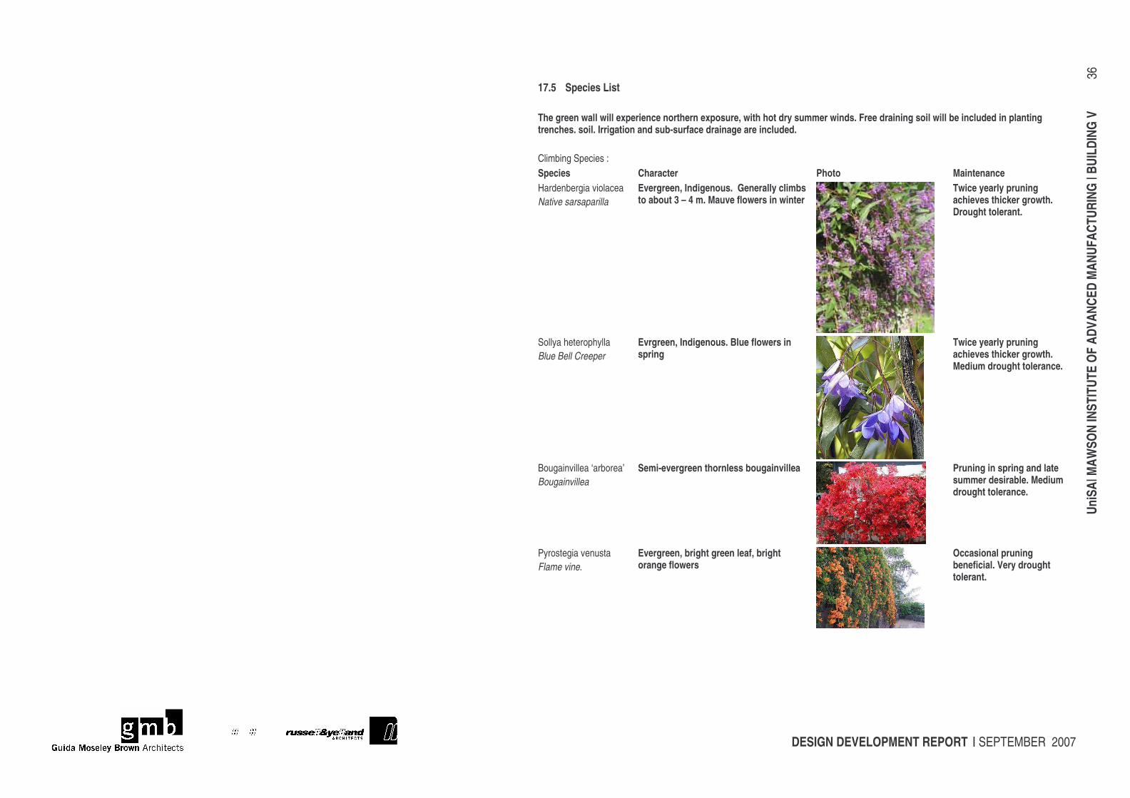
DESIGN DEVELOPMENT REPORT | SEPTEMBER 2007
UniS
A| M
AWSO
N IN
STIT
UTE
OF A
DVAN
CED
MAN
UFAC
TURI
NG |
BUIL
DING
V
36
17.5 Species List The green wall will experience northern exposure, with hot dry summer winds. Free draining soil will be included in planting trenches. soil. Irrigation and sub-surface drainage are included. Climbing Species : Species Character Photo Maintenance Hardenbergia violacea Native sarsaparilla
Evergreen, Indigenous. Generally climbs to about 3 – 4 m. Mauve flowers in winter
Twice yearly pruning achieves thicker growth. Drought tolerant.
Sollya heterophylla Blue Bell Creeper
Evrgreen, Indigenous. Blue flowers in spring
Twice yearly pruning achieves thicker growth. Medium drought tolerance.
Bougainvillea ‘arborea’ Bougainvillea
Semi-evergreen thornless bougainvillea
Pruning in spring and late summer desirable. Medium drought tolerance.
Pyrostegia venusta Flame vine.
Evergreen, bright green leaf, bright orange flowers
Occasional pruning beneficial. Very drought tolerant.
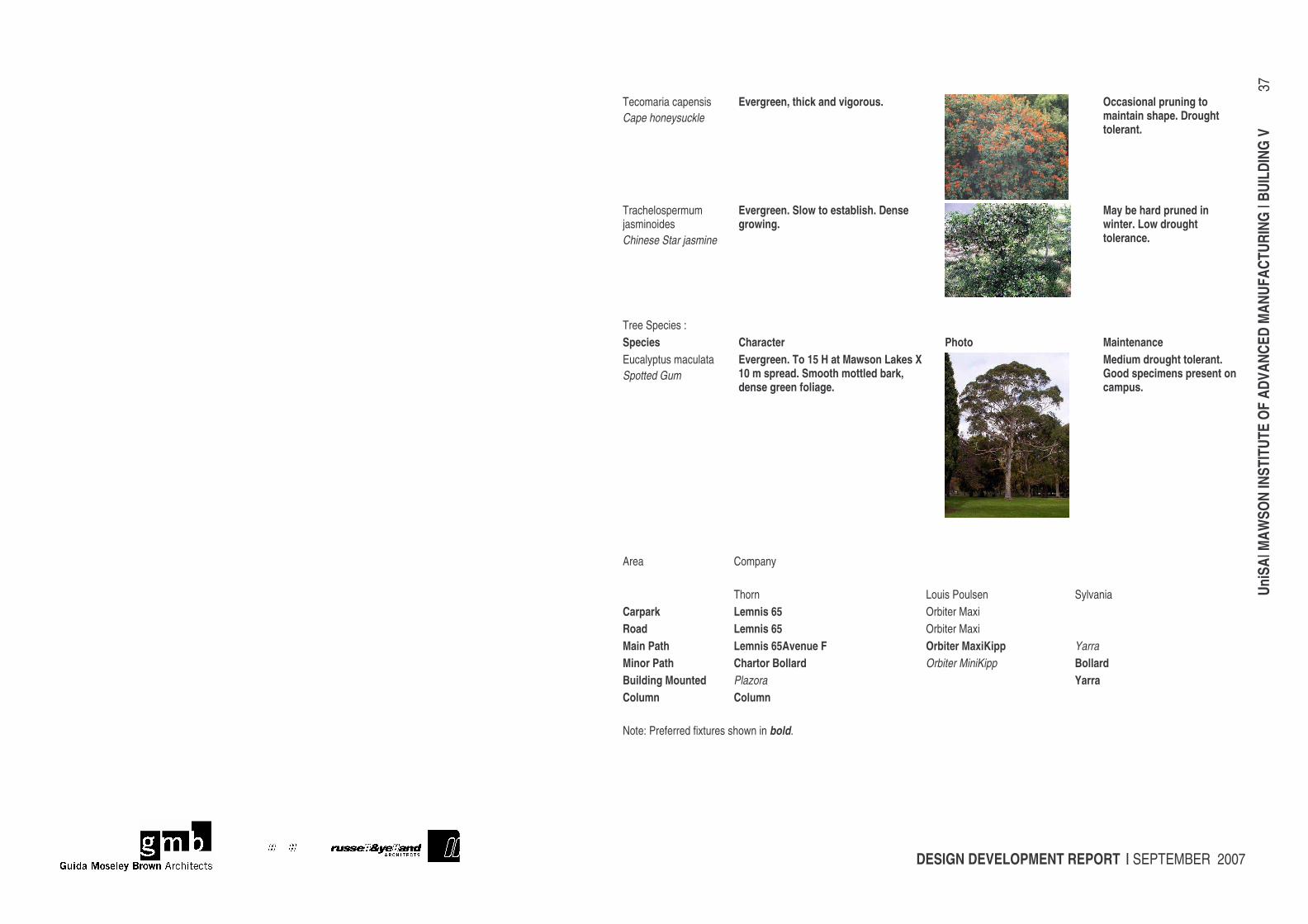
DESIGN DEVELOPMENT REPORT | SEPTEMBER 2007
UniS
A| M
AWSO
N IN
STIT
UTE
OF A
DVAN
CED
MAN
UFAC
TURI
NG |
BUIL
DING
V
37
Tecomaria capensis Cape honeysuckle
Evergreen, thick and vigorous.
Occasional pruning to maintain shape. Drought tolerant.
Trachelospermum jasminoides Chinese Star jasmine
Evergreen. Slow to establish. Dense growing.
May be hard pruned in winter. Low drought tolerance.
Tree Species : Species Character Photo Maintenance Eucalyptus maculata Spotted Gum
Evergreen. To 15 H at Mawson Lakes X 10 m spread. Smooth mottled bark, dense green foliage.
Medium drought tolerant. Good specimens present on campus.
Area Company
Thorn Louis Poulsen Sylvania Carpark Lemnis 65 Orbiter Maxi Road Lemnis 65 Orbiter Maxi Main Path Lemnis 65Avenue F Orbiter MaxiKipp Yarra Minor Path Chartor Bollard Orbiter MiniKipp Bollard Building Mounted Plazora Yarra Column Column Note: Preferred fixtures shown in bold.
DESIGN DEVELOPMENT REPORT | SEPTEMBER 2007
UniS
A| M
AWSO
N IN
STIT
UTE
OF A
DVAN
CED
MAN
UFAC
TURI
NG |
BUIL
DING
V
38
18 GREEN STAR AND ESD INTIATIVES
18.1 General Principles Since 2006 UniSA has mandated that all new buildings with a construction value greater than $1m will be designed and constructed to achieve a Five Star Green Star rating. UniSA has briefed that the pilot Education Green Star Tool framework in accordance with Green Council of Australia standards for Educational Institutions is applied to this project New Building for MIAM and is aiming to achieve a Five Star Green Star rating under that tool. The Principal Consultant and their team will be utilising the pilot Education Green Star Tool framework which is being launched in May 2007. They are formulating the necessary documentation to enable the project to be assessed against the pilot Education Tool. This project will provide valuable feedback to the Green Council in testing how well a tertiary sector research facility designed in accordance with best ESD principles for a building of its type (a mix of research laboratory and office building) matches the expectations of the Education Green Star Tool. The current status of this process is attached as APPENDIX F: GREEN STAR MATRIX. The UniSA Design and Construction Guidelines outline its Environmental Sustainability Policy and Guidelines. These have been developed to ensure that all future developments of UniSA campuses are based on sound environmental sustainable principles. All stages and aspects of the project are expected to be based on these principles. The following principles apply to this project: • Utilisation of existing infrastructure where viable and practical • Maximisation of lifecycle and future adaptability of buildings • Protection and enhancement of the site • Design and building of energy efficient buildings • Optimisation of Engineering Services designs • Creation of health building • Selection of low impact construction materials • Provision of high air quality (internal and external) • Reduction of impact of materials on indoor air quality • Reduction of noise • Optimisation of light • Efficient use of water • Minimisation of waste The consultant team includes an ESD specialist/ Green Star Accredited Professional. This specialist sub-consultant has been providing significant direction to the team. They have undertaken a significant assessment of the environmental issues surrounding the site, the brief and UniSA standard requirements to ensure that the project has minimal impact on the environment and that energy efficiency is achieved where ever possible.
18.2 ESD Initiatives Included in Project
Passive Design Passive design principles have been incorporated where ever practicable. Passive design features include: • Building Orientation-The building has been planned with a predominant east west axis enabling a strong north-south orientation.
Glazing to the east and west has been minimised and controlled. • Shading- The laboratories incorporate a peristitial service corridor that is semi- enclosed providing sensible shading to the
laboratories. • Low VOC Emissions- materials with low VOC emissions will be documented throughout the project such as low VOC paints and
adhesives
DESIGN DEVELOPMENT REPORT | SEPTEMBER 2007
UniS
A| M
AWSO
N IN
STIT
UTE
OF A
DVAN
CED
MAN
UFAC
TURI
NG |
BUIL
DING
V
39
Existing Infrastructure The Mawson Lakes Campus has significant campus infrastructure that will be utilised to support the site and building infrastructure solutions for this project. These include: • Central thermal plant • Central gas supply • Potable water supply via campus main tunnel • Recycled water system • Sophisticated Building Management System • Comprehensive fibre and data network
Adaptability of Building The following features have been incorporated in the design of this project to enable sound future flexibility and adaptability: • The laboratory areas have been designed to enable future flexibility and adaptability through the incorporation of a peristitial service
corridor which focuses all the service entry points to one key zone enabling changes to be made easily and without disruption to laboratory activities
• A systematic grid to the layout of the laboratory benches further enhances this flexibility • All laboratory partition walls are non-load bearing and have been designed without any service encumbrances and so they can be
easily relocated • The office accommodation is 75% open plan enabling a high level of flexibility and adaptability • Ceilings and floor finishes are proposed to be constructed prior to partition walls of dedicated offices enabling ease of removal and/ or
relocation as future needs demand • Structure of building is beam and column to enable internal arrangements to be non-load bearing and alterable
Building Management System Existing campus Building Management System is to be extended to the new building to control mechanical and lighting systems.
Lighting and Lighting Controls High efficient luminaries incorporating T5 lamps are to generally be used throughout the building. The use of lighting controls such as PE Cells and occupany sensors are to be used throughout the new building.
Operational Waste Management The building has been designed with specific and adequate space in both the laboratory and office areas to enable recycling bins to be provided as required.
Material Selection Selection of Materials for this project will consider the following: • Whether the product comes from a renewable source • Whether the product is recycled or recyclable • Whether the materials can be sourced locally • Durability and low maintenance properties • Selection of materials that do not adversely affect indoor air quality
Indigenous Vegetation Provision has been made to incorporate locally indigenous plant species into the landscaped areas associated with the building. These will include locally rare grass-like species which previously occurred on the site.
DESIGN DEVELOPMENT REPORT | SEPTEMBER 2007
UniS
A| M
AWSO
N IN
STIT
UTE
OF A
DVAN
CED
MAN
UFAC
TURI
NG |
BUIL
DING
V
40
Transportation The building concept design incorporates bicycle parking for both staff and visitors.
Construction Process The successful contractor will be contractually obliged to develop an Environmental Management Plan for the project. The Waste Management Plan shall include the following minimal information: • strategy for sorting construction waste • strategy for removal of construction waste • recycling and reuse plan • pollution controls • resource conservation • noise minimisation
Projected Chemical Usage in MIAM Laboratories The forecasted chemical requirements for the MIAM laboratories are small. The reagent requirements for experimentation; a range of flammables, acids and corrosives, is estimated to be approximately 30 litres per annum. The emission of these reagents, when used in plasma processing, is effectively zero since the process by-products are generally a mixture of water vapour, carbon dioxide, carbon monoxide and methane. The greatest use of chemicals will be for cleaning purposes. The laboratories generally use solutions of acetone, ethanol, isopropyl alcohol and commercial bleach solutions. For all the laboratories the total, combined usage of these two chemicals is estimated to be approximately 300 litres per annum. Given the high standards of the fume cupboard design and associated filtering it is not envisaged that there are any specific air or water quality issues emanating from this building.
DESIGN DEVELOPMENT REPORT | SEPTEMBER 2007
UniS
A| M
AWSO
N IN
STIT
UTE
OF A
DVAN
CED
MAN
UFAC
TURI
NG |
BUIL
DING
V
41
19 HERITAGE STATUS The Mawson Lakes Campus of UniSA and its buildings are not on the Heritage Register. Aboriginal Heritage In 2002 UniSA commissioned an Indigenous Cultural Heritage survey prepared by Rhondda Harris for particular proposed development sites at the Mawson Lakes Campus. This survey informed the monitoring of the excavation process for those developments. The team responsible for managing the monitoring developed a new process of site investigation (core hole drilling the footprint and main services run at 1 metre intervals). This process enabled the successful mitigation of the risks and costs associated with monitoring for possible items of significance during the project construction period. This process was later adopted by other developers including Land Management Corporation and City of Salisbury. In 2006 UniSA extended the Indigenous Cultural Heritage study further by commissioning a full study of the entire campus prepared by Vivienne Wood. There is significant evidence to indicate that parts of the Mawson Lakes area are of indigenous significance as it operated as a major residential centre for the Kaurna people in past centuries. The main aims of the study were to: • Identify areas of Aboriginal heritage significance in relation to the current South Australian Aboriginal Heritage Act 1988 • Determine the sensitivity level of significance of any areas identified • Inform UniSA of the likelihood of disturbing an area deemed significant or discovering an artefact through building works, and what
might potentially be discovered on such a building site In the main and over the course of the past one hundred years, the Mawson Lakes Campus’ original land surface has been significantly excavated, levelled and filled to varying degrees. There is however proven sensitivity of the surrounding areas such as the wider Mawson Lakes Economic Development Project area and Technology Park. So the potential remains for burial sites or items of significance to be discovered during construction excavation work on the campus proper. The 2006 Indigenous Cultural Heritage Study prepared by Vivienne Wood highlights the potentially high sensitivity zones of the Mawson Lakes Campus. The development site for this building project is included in that zone. UniSA is currently negotiating with the Kaurna’s representative group, Tappa Iri, to undertake sub-terrane site investigations prior to the commencement of construction. The methodology being proposed is a combination of two geophysical methods: • Electromagnetic induction (EMI), and • Ground penetrating radar (GPR). The EMI method is an effective tool for quickly covering large spatial areas with the aim of identifying broader disturbances in subsurface materials, including ‘smoking pits’. The GPR method is accepted globally as one of the best methods for locating subsurface objects and for defining areas of subsurface disturbance, including pits and burials. This dual-method approach increases the likelihood that potentially subtle features will be resolved because it accounts for likely variations in electromagnetic responses from different burial models. At a recent meeting the Kaurna and Tappa Iri have accepted this method of pre-construction subsurface investigation. A formal agreement between UniSA and Kaurna is currently being prepared to enable the geophysical analysis to take place by the end of June in the presence of Kaurna monitors. UniSA has advised the Kaurna that there is flexibility with both the placement of the building on site and the footprint of the building. So in the event that something of significance is uncovered through the subsurface investigations, the project has the capacity to work around the significant item(s). The Mawson Lakes Campus of UniSA is not subject to any specific native titles land claim.
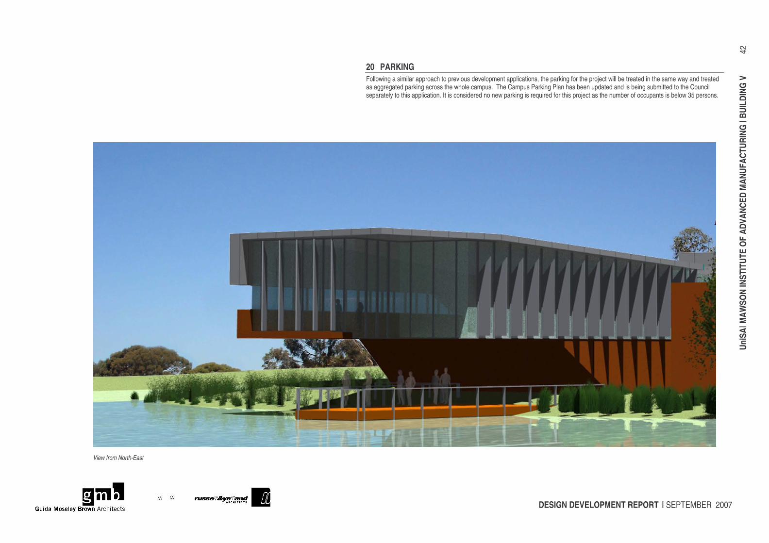
DESIGN DEVELOPMENT REPORT | SEPTEMBER 2007
UniS
A| M
AWSO
N IN
STIT
UTE
OF A
DVAN
CED
MAN
UFAC
TURI
NG |
BUIL
DING
V
42
20 PARKING Following a similar approach to previous development applications, the parking for the project will be treated in the same way and treated as aggregated parking across the whole campus. The Campus Parking Plan has been updated and is being submitted to the Council separately to this application. It is considered no new parking is required for this project as the number of occupants is below 35 persons.
View from North-East
DESIGN DEVELOPMENT REPORT | SEPTEMBER 2007
UniS
A| M
AWSO
N IN
STIT
UTE
OF A
DVAN
CED
MAN
UFAC
TURI
NG |
BUIL
DING
V
43
21 COST PLAN Rider Levett Bucknall were appointed Cost Managers by UniSA for this project. The following is extracted from their PCG report No. 3:
21.1 Approved Budget Summary For the purposes of this report we will be reporting against a budget value of $11.25M (Excluding GST), as directed by UniSA. The project budget is inclusive of all project costs as indicated in the initial project brief.
21.2 Professional Fees The current budget is inclusive of $1,431,265 (Excl. GST) for professional fees as advised by UniSA. This is inclusive of all consultant fees and sundry costs directly managed by UniSA. The total current contract amount for fees is $1,189,265 (as advised by UniSA 6 August 2007).
21.3 Construction Contingency The current estimate includes the following contingency allowances;
• Design Development 5% • Construction 5%
21.4 Risks We identify the following as areas of risk, which could impact on the cost and program of the project: • Budget adequacy • Latent ground conditions • Inclement weather (time risk) • Industrial disputation • Labour and/or subcontractor shortages and market volatility • Aboriginal / Indigenous Issues including discovery of artefacts during construction (low risk) • Additional Client Initiated Works which could impact on Construction Program and the Critical Path • Leading edge building design • Extent of landscaping / urban design
21.5 Items Specifically Excluded From This Cost Report The following is a summary of items specifically excluded from this project budget: • UniSA Staff and down time costs including UniSA property unit costs • Pre-project expenses • Contaminated Ground Removal and Reinstatement • Rock Excavation • Murals and works of art • Holding costs and interest charges • Land and legal costs • Marketing allowances • Specialist Equipment including laboratory equipment • Goods and Services Tax
21.6 Budget Status The following is a summary of the current approved budget and estimate;
DESIGN DEVELOPMENT REPORT | SEPTEMBER 2007
UniS
A| M
AWSO
N IN
STIT
UTE
OF A
DVAN
CED
MAN
UFAC
TURI
NG |
BUIL
DING
V
44
We note that there is no change since the previous report.
Item Component Approved Budget Order of Cost Estimate 17 May 2007
Variance
1.0 Building Works $7,386,000 $8,870,000 +$1,484,000
2.0 Furniture, Fittings & Equipment
$765,000 $765,000 Nil
Loose Furniture Included above Included above -
Systems Furniture Included above Included above -
Special Equipment Included above Included above -
FFE Contingency Included above Included above -
3.0 Fees
Principal Consultants & Rider Hunt $1,189,265 $1,190,000 +$735
Green star consultancy fees - separate - - -
Statutory & legal – CITB, DDA, DAC Levy
$71,000 $71,000 Nil
Miscellaneous Fees including disbursements
$71,000 $71,000 Nil
Fee Contingency $100,000 $100,000 Nil
4.0 Commissioning Costs
Relocation Costs $63,000 $63,000 Nil
IT Infrastructure Costs $63,000 $63,000 Nil
Contingency (included in 4.1) $8,000 $8,000 Nil
5.0 Corporate Costs
Corporate signage $63,000 $63,000 Nil
Miscellaneous costs $63,000 $63,000 Nil
Contingency $3,000 $3,000 Nil
6.0 Escalation to Completion $1,404,735 $662,000 ($742,735)
TOTAL $11,250,000 $11,992,000 +$742,000
21.7 Current Status At the last PCG it was reported that the team has identified potential savings up to $800,000 and an updated estimate was to be prepared to determine the impact of those savings adopted. It was hoped that this update would be completed in time for this PCG. This estimate update is currently being prepared however we are awaiting the following for inclusion in the estimate; • Engineering Service update (estimates based on developed design) • Landscaping update (to identify the extent of project scope and test the budget allowance) • Structural update, in particular footing advice based on the outcome of geotechnical investigation. In parallel with the estimate update we have reviewed several façade options. The options to be presented by GMB & R&Y result in the following cost savings;
DESIGN DEVELOPMENT REPORT | SEPTEMBER 2007
UniS
A| M
AWSO
N IN
STIT
UTE
OF A
DVAN
CED
MAN
UFAC
TURI
NG |
BUIL
DING
V
45
1) West Façade comprising of opaque glass planks and clear double glazed windows. Introduction of a plasterboard partition wall behind some areas of the glass planks. Each option represents a varied combination of the above elements. Option 1 Cost saving of $35,000 Option 2 Cost saving of $42,000
2) Green wall (northern elevation) comprising profiled wire mesh fence Option 1 Cost saving of $63,000
The resultant savings are in line with the target savings identified as part of the saving strategy.
21.8 Expenditure Current actual expenditure to date can be summarised as follows: • Fees including disbursements $182,302 • Corporate Costs $4,120 Note that the above expenditure is in accordance with UniSA’s advice received on 6 August 2007.
21.9 Upcoming Activities • Completion of updated estimate (targeted for use at VM session referred to below) including specific review of; • Engineering Services • Landscaping • Structural design development • Value Management Review (WM session scheduled for 17 August 2007) • Completion of Design Development estimate to meet the design documentation milestone of 28 August 2007. This version will
incorporate outcomes of the VM session.
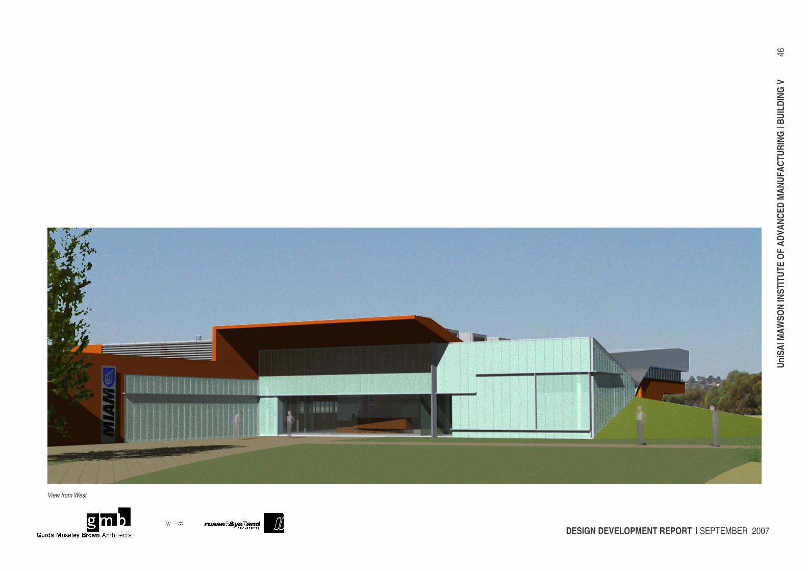
DESIGN DEVELOPMENT REPORT | SEPTEMBER 2007
UniS
A| M
AWSO
N IN
STIT
UTE
OF A
DVAN
CED
MAN
UFAC
TURI
NG |
BUIL
DING
V
46
View from West
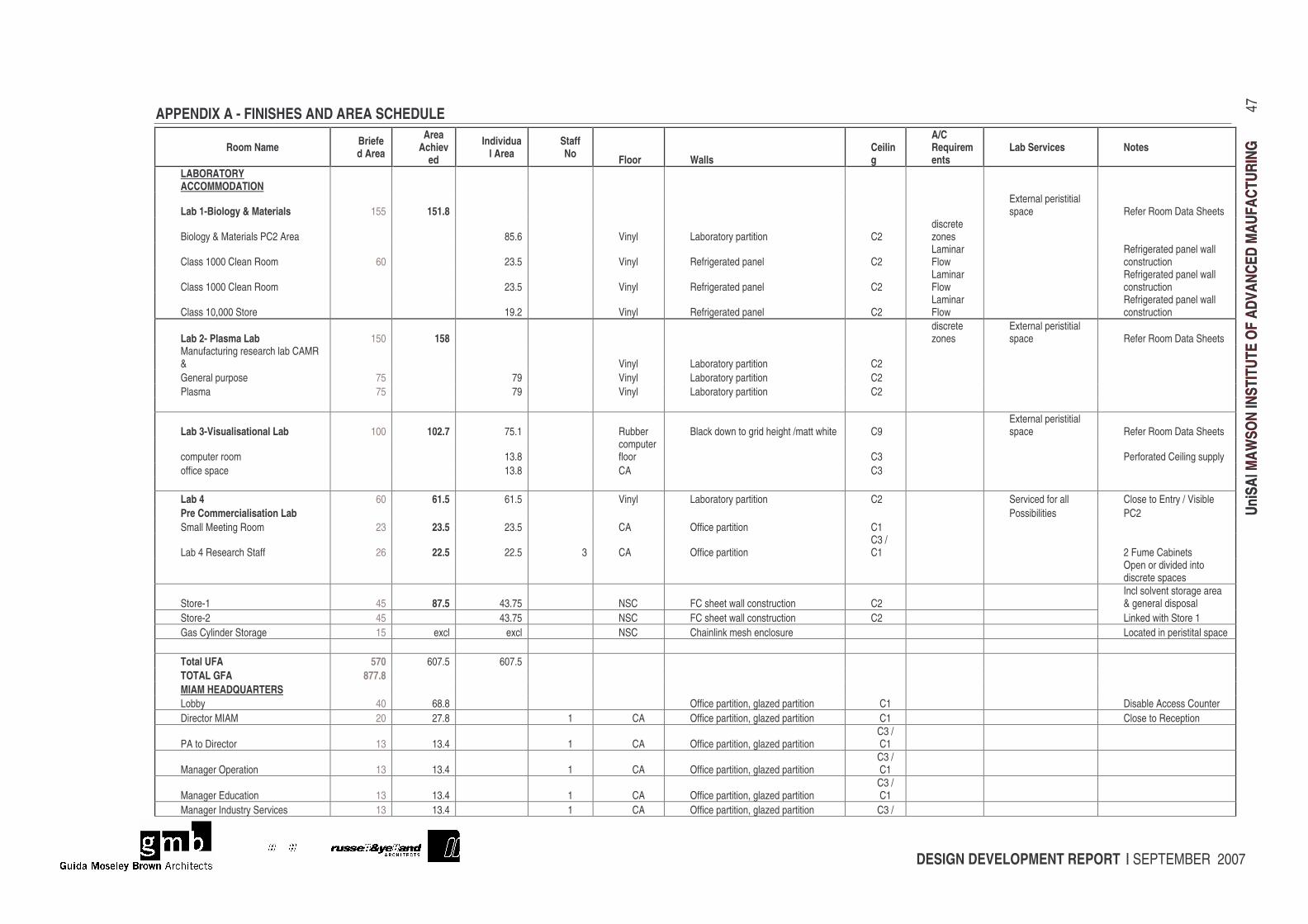
DESIGN DEVELOPMENT REPORT | SEPTEMBER 2007
UniS
A| M
AWSO
N IN
STIT
UTE
OF A
DVAN
CED
MAU
FACT
URIN
G
47
UniS
A| M
AWSO
N IN
STIT
UTE
OF A
DVAN
CED
MAU
FACT
URIN
G
APPENDIX A - FINISHES AND AREA SCHEDULE
Room Name Briefed Area
Area Achiev
ed
Individual Area
Staff No Floor Walls
Ceiling
A/C Requirements
Lab Services Notes
LABORATORY ACCOMMODATION
Lab 1-Biology & Materials 155 151.8 External peristitial space Refer Room Data Sheets
Biology & Materials PC2 Area 85.6 Vinyl Laboratory partition C2 discrete zones
Class 1000 Clean Room 60 23.5 Vinyl Refrigerated panel C2 Laminar Flow
Refrigerated panel wall construction
Class 1000 Clean Room 23.5 Vinyl Refrigerated panel C2 Laminar Flow
Refrigerated panel wall construction
Class 10,000 Store 19.2 Vinyl Refrigerated panel C2 Laminar Flow
Refrigerated panel wall construction
Lab 2- Plasma Lab 150 158 discrete zones
External peristitial space Refer Room Data Sheets
Manufacturing research lab CAMR & Vinyl Laboratory partition C2 General purpose 75 79 Vinyl Laboratory partition C2 Plasma 75 79 Vinyl Laboratory partition C2
Lab 3-Visualisational Lab 100 102.7 75.1 Rubber Black down to grid height /matt white C9 External peristitial space Refer Room Data Sheets
computer room 13.8 computer floor C3 Perforated Ceiling supply
office space 13.8 CA C3 Lab 4 60 61.5 61.5 Vinyl Laboratory partition C2 Serviced for all Close to Entry / Visible Pre Commercialisation Lab Possibilities PC2 Small Meeting Room 23 23.5 23.5 CA Office partition C1
Lab 4 Research Staff 26 22.5 22.5 3 CA Office partition C3 / C1 2 Fume Cabinets
Open or divided into discrete spaces
Store-1 45 87.5 43.75 NSC FC sheet wall construction C2 Incl solvent storage area & general disposal
Store-2 45 43.75 NSC FC sheet wall construction C2 Linked with Store 1 Gas Cylinder Storage 15 excl excl NSC Chainlink mesh enclosure Located in peristital space Total UFA 570 607.5 607.5 TOTAL GFA 877.8 MIAM HEADQUARTERS Lobby 40 68.8 Office partition, glazed partition C1 Disable Access Counter Director MIAM 20 27.8 1 CA Office partition, glazed partition C1 Close to Reception
PA to Director 13 13.4 1 CA Office partition, glazed partition C3 / C1
Manager Operation 13 13.4 1 CA Office partition, glazed partition C3 / C1
Manager Education 13 13.4 1 CA Office partition, glazed partition C3 / C1
Manager Industry Services 13 13.4 1 CA Office partition, glazed partition C3 /
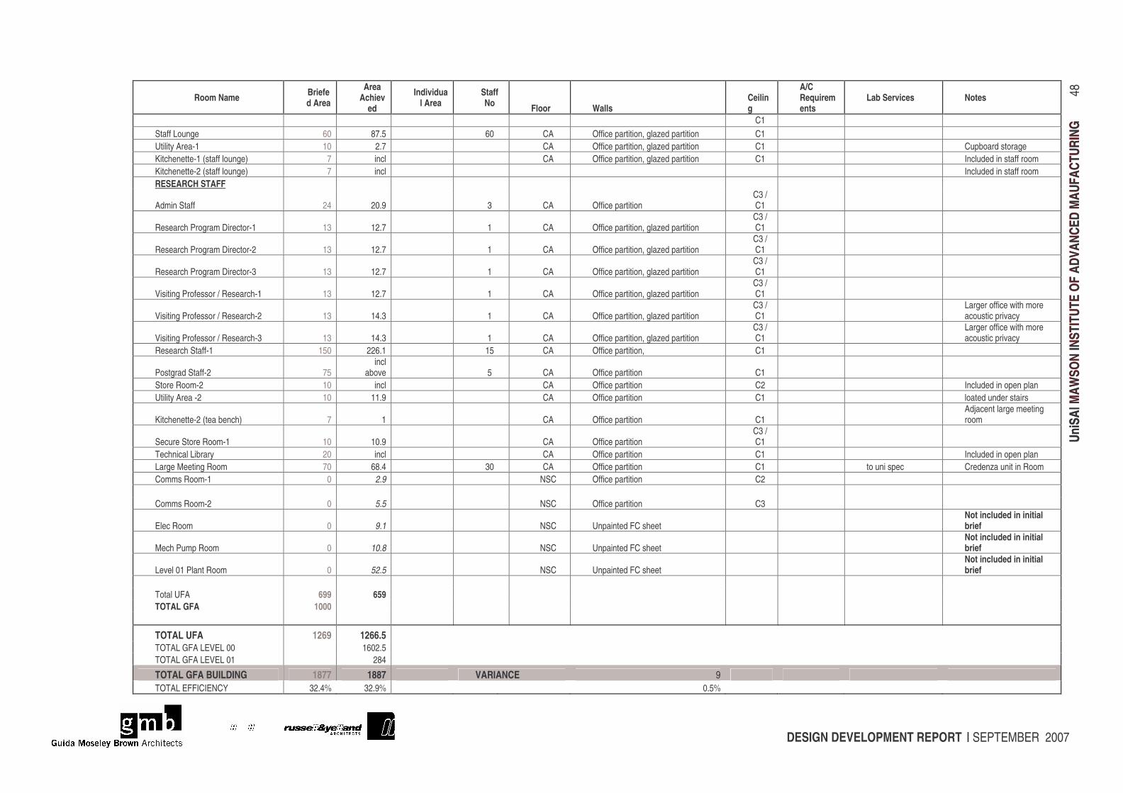
DESIGN DEVELOPMENT REPORT | SEPTEMBER 2007
UniS
A| M
AWSO
N IN
STIT
UTE
OF A
DVAN
CED
MAU
FACT
URIN
G
48
UniS
A| M
AWSO
N IN
STIT
UTE
OF A
DVAN
CED
MAU
FACT
URIN
G
Room Name Briefed Area
Area Achiev
ed
Individual Area
Staff No Floor Walls
Ceiling
A/C Requirements
Lab Services Notes
C1 Staff Lounge 60 87.5 60 CA Office partition, glazed partition C1 Utility Area-1 10 2.7 CA Office partition, glazed partition C1 Cupboard storage Kitchenette-1 (staff lounge) 7 incl CA Office partition, glazed partition C1 Included in staff room Kitchenette-2 (staff lounge) 7 incl Included in staff room RESEARCH STAFF
Admin Staff 24 20.9 3 CA Office partition C3 / C1
Research Program Director-1 13 12.7 1 CA Office partition, glazed partition C3 / C1
Research Program Director-2 13 12.7 1 CA Office partition, glazed partition C3 / C1
Research Program Director-3 13 12.7 1 CA Office partition, glazed partition C3 / C1
Visiting Professor / Research-1 13 12.7 1 CA Office partition, glazed partition C3 / C1
Visiting Professor / Research-2 13 14.3 1 CA Office partition, glazed partition C3 / C1
Larger office with more acoustic privacy
Visiting Professor / Research-3 13 14.3 1 CA Office partition, glazed partition C3 / C1
Larger office with more acoustic privacy
Research Staff-1 150 226.1 15 CA Office partition, C1
Postgrad Staff-2 75 incl
above 5 CA Office partition C1 Store Room-2 10 incl CA Office partition C2 Included in open plan Utility Area -2 10 11.9 CA Office partition C1 loated under stairs
Kitchenette-2 (tea bench) 7 1 CA Office partition C1 Adjacent large meeting room
Secure Store Room-1 10 10.9 CA Office partition C3 / C1
Technical Library 20 incl CA Office partition C1 Included in open plan Large Meeting Room 70 68.4 30 CA Office partition C1 to uni spec Credenza unit in Room Comms Room-1 0 2.9 NSC Office partition C2 Comms Room-2 0 5.5 NSC Office partition C3
Elec Room 0 9.1 NSC Unpainted FC sheet Not included in initial brief
Mech Pump Room 0 10.8 NSC Unpainted FC sheet Not included in initial brief
Level 01 Plant Room 0 52.5 NSC Unpainted FC sheet Not included in initial brief
Total UFA 699 659 TOTAL GFA 1000
TOTAL UFA 1269 1266.5 TOTAL GFA LEVEL 00 1602.5 TOTAL GFA LEVEL 01 284
TOTAL GFA BUILDING 1877 1887 VARIANCE 9 TOTAL EFFICIENCY 32.4% 32.9% 0.5%
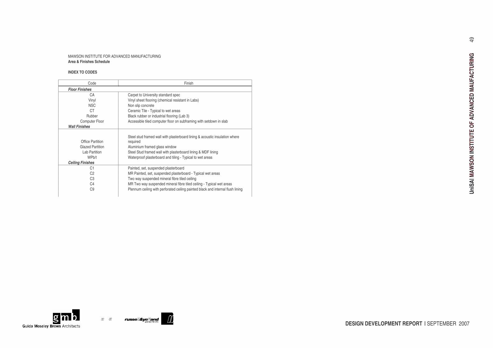
DESIGN DEVELOPMENT REPORT | SEPTEMBER 2007
UniS
A| M
AWSO
N IN
STIT
UTE
OF A
DVAN
CED
MAU
FACT
URIN
G
49
UniS
A| M
AWSO
N IN
STIT
UTE
OF A
DVAN
CED
MAU
FACT
URIN
G
MAWSON INSTITUTE FOR ADVANCED MANUFACTURING Area & Finishes Schedule INDEX TO CODES
Code Finish Floor Finishes
CA Carpet to University standard spec Vinyl Vinyl sheet flooring (chemical resistant in Labs) NSC Non slip concrete CT Ceramic Tile - Typical to wet areas
Rubber Black rubber or industrial flooring (Lab 3) Computer Floor Accessible tiled computer floor on subframing with setdown in slab
Wall Finishes
Office Partition Steel stud framed wall with plasterboard lining & acoustic insulation where required
Glazed Partition Aluminium framed glass window Lab Partition Steel Stud framed wall with plasterboard lining & MDF lining
WPb/t Waterproof plasterboard and tiling - Typical to wet areas Ceiling Finishes
C1 Painted, set, suspended plasterboard C2 MR Painted, set, suspended plasterboard - Typical wet areas C3 Two way suspended mineral fibre tiled ceiling C4 MR Two way suspended mineral fibre tiled ceiling - Typical wet areas C9 Plennum ceiling with perforated ceiling painted black and internal flush lining
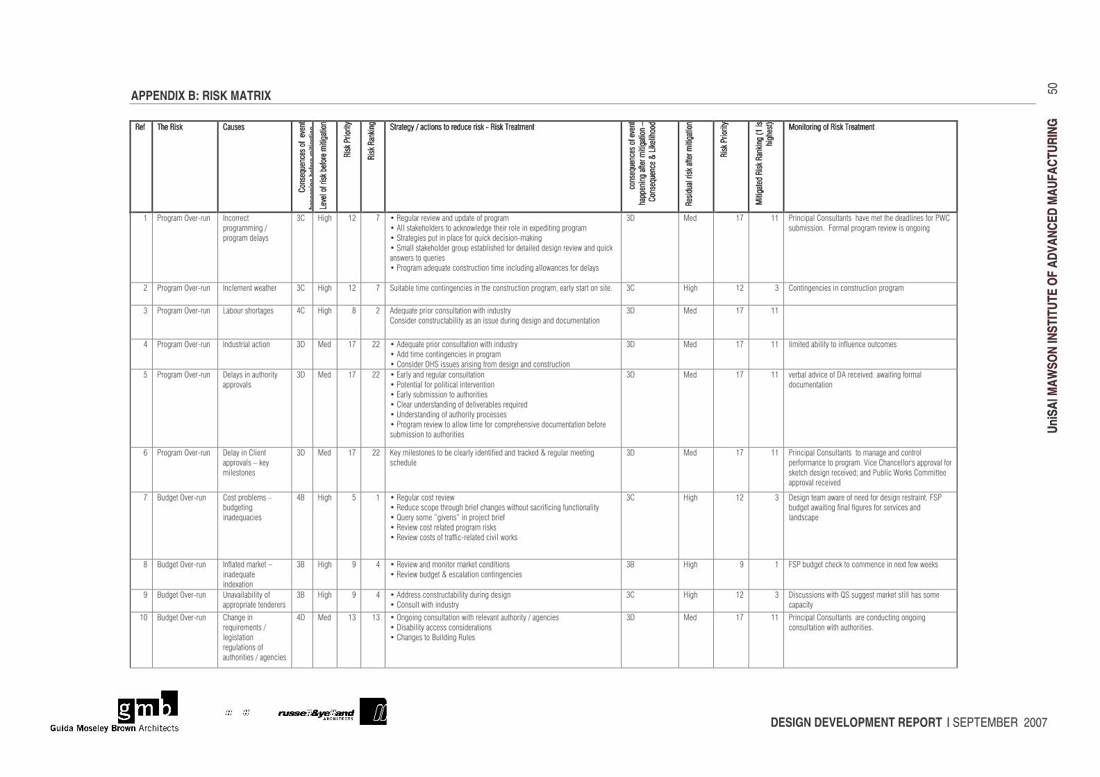
DESIGN DEVELOPMENT REPORT | SEPTEMBER 2007
UniS
A| M
AWSO
N IN
STIT
UTE
OF A
DVAN
CED
MAU
FACT
URIN
G
50
UniS
A| M
AWSO
N IN
STIT
UTE
OF A
DVAN
CED
MAU
FACT
URIN
G
APPENDIX B: RISK MATRIX ���������������� �������������������������������� ������������������������
����������� ���������
����������� ���������
����������� ���������
����������� ���������
������������� ����������� ��
������������� ����������� ��
������������� ����������� ��
������������� ����������� ���� ��
������ ��������� ����������� �
������ ��������� ����������� �
������ ��������� ����������� �
������ ��������� ����������� � �� ��
������� ����
������� ����
������� ����
������� ������ ��
����������
����������
����������
������������ ��
��������������� ���� ��������������������������� ���� ��������������������������� ���� ��������������������������� ���� ����������������������������������������������������������������������������
� ����������� ��������
� ����������� ��������
� ����������� ��������
� ����������� ��������
������������������������ ��
������������������������ ��
������������������������ ��
������������������������ �� �� ��
����������!������� �
����������!������� �
����������!������� �
����������!������� � �� ��
��������������������������� �
��������������������������� �
��������������������������� �
��������������������������� � �� ��
������� ����
������� ����
������� ����
������� ������ ��
"�������������������
"�������������������
"�������������������
"��������������������#$����
�#$����
�#$����
�#$����
�������%
�������%
�������%
�������%�� ��
" ��� ����� ���������������" ��� ����� ���������������" ��� ����� ���������������" ��� ����� �������������������
$� �� �����&�������� '�� ������
�� �����������
�� ������������
(� )���� $*� +� ,��������������-������������ ���� �����
,�.�������� ������� ���� -������������� �������/����������� �����
,�������������������������� ������������� ��������
,������������ ������� ���������������� �����������������������-����������
���-����� ���������
,��� ��������������� �������� �������������������� -������� ���������
(0� "��� $+� $$� ���������� ����������������������������������� ���1�
�������� �2��3 ������� ����������-���� �� ����
*� �� �����&�������� '���������-������� (� )���� $*� +� ��������������� �������������������� �������� ���� ����4������������� ������2� (� )���� $*� (� ���������������� �������� ���� �����
(� �� �����&�������� ��� ����� ������� 5� )���� 6� *� .����������� ��� �������� ��-�������������
�������� ���������������������������������������������� ��������� ��
(0� "��� $+� $$� ��
5� �� �����&�������� '�������������� �� (0� "��� $+� **� ,�.����������� ��� �������� ��-�������������
,�.��������� ����������������� �����
,� �������&)������������������� �������������� �������� ��
(0� "��� $+� $$� ����������������� ����������� ��� ����
7� �� �����&�������� 0������������� �����
���� �����
(0� "��� $+� **� ,�8������������������ �������� ��
,�� ��������� ��� ������������������ ��
,�8������������� ��� ����� �������
,�������������������� ������������������������
,�9������������� ������ ������� �������
,��� ����������-�� ���� -������� ��� ������������� ��������� ����� ���
�������� ��� ����� �������
(0� "��� $+� $$� �������������� ��0.���������:��-�������� �����
� ��������� ��
;� �� �����&�������� 0��������������
���� ����� ����
������ ����
(0� "��� $+� **� <��������� ����� ����������������������������������!�����������������
���������
(0� "��� $+� $$� ���������� ������������ ������������� ��� ��
���� �������� ��� ����2�=����������� �>������ ����� ��
���������������������?������������1 ��� ��������
���� �������������
+� @������&�������� ����� ������ �
����������
�������������
5@� )���� 7� $� ,���������� ��������-�
,���������� ������ ������������������-��� ��������������������� �������
,�A������ ���B������B������ C����������
,������-�� ������������� ����������
,������-�� ���� ������������������������- ���
(� )���� $*� (� 0������������-���� �������� ������������������2�3���
��������-���������������������� ���������������
����������
6� @������&�������� '�������������� �
�����������
����/��� ��
(@� )���� D� 5� ,������-������ ��� ��������� ����� ���
,������-��������!��������� ��� ������������
(@� )���� D� $� 3���������������� �� ������������/����-�-����
D� @������&�������� 9�������������� ��
���� �����������������
(@� )���� D� 5� ,�.�������� �����������������������������
,� ������-�������������
(� )���� $*� (� 0������� ���-����A��������������������������� ���
���������
$E� @������&�������� ���������
���������������
��������� ��
�������� ��� ��
���� ������������������
50� "��� $(� $(� ,�&�� ����� �������� ��-����������������� ����������������
,�0������������������ ��������� ���
,��������� �@��������������
(0� "��� $+� $$� ���������� ���������������� ��������� �� ����
� �������� ��-�������� ������2�
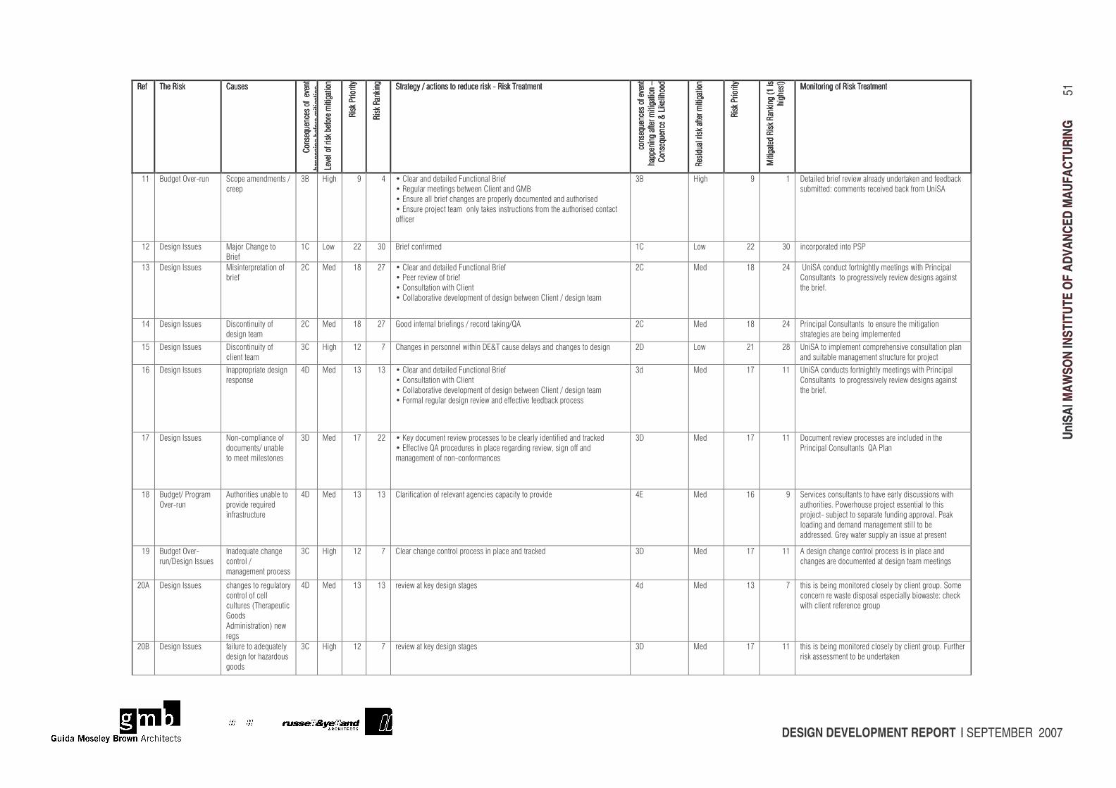
DESIGN DEVELOPMENT REPORT | SEPTEMBER 2007
UniS
A| M
AWSO
N IN
STIT
UTE
OF A
DVAN
CED
MAU
FACT
URIN
G
51
UniS
A| M
AWSO
N IN
STIT
UTE
OF A
DVAN
CED
MAU
FACT
URIN
G
���������������� �������������������������������� ������������������������
����������� ���������
����������� ���������
����������� ���������
����������� ���������
������������� ����������� ��
������������� ����������� ��
������������� ����������� ��
������������� ����������� ���� ��
������ ��������� ����������� �
������ ��������� ����������� �
������ ��������� ����������� �
������ ��������� ����������� � �� ��
������� ����
������� ����
������� ����
������� ������ ��
����������
����������
����������
������������ ��
��������������� ���� ��������������������������� ���� ��������������������������� ���� ��������������������������� ���� ����������������������������������������������������������������������������
� ����������� ��������
� ����������� ��������
� ����������� ��������
� ����������� ��������
������������������������ ��
������������������������ ��
������������������������ ��
������������������������ �� �� ��
����������!������� �
����������!������� �
����������!������� �
����������!������� � �� ��
��������������������������� �
��������������������������� �
��������������������������� �
��������������������������� � �� ��
������� ����
������� ����
������� ����
������� ������ ��
"�������������������
"�������������������
"�������������������
"��������������������#$����
�#$����
�#$����
�#$����
�������%
�������%
�������%
�������%�� ��
" ��� ����� ���������������" ��� ����� ���������������" ��� ����� ���������������" ��� ����� �������������������
$$� @������&�������� �� ����������������
������
(@� )���� D� 5� ,�������������������3����� ����@�����
,���������������������-��������������F"@�
,�8������������������������������ ������� ����������������� ������
,�8�������� C���������� ������������������ ����� ���������� ������� ������
�������
(@� )���� D� $� 0�������������������-�������������������������������
���������:�� ���������������������� ��9���.�
$*� 0������'������ "�C ��������� �
@�����
$� � -� **� (E� @������ �������� $� � -� **� (E� ��� �� ��������� �����
$(� 0������'������ "�������������� �� ��
������
*� "��� $6� *+� ,�������������������3����� ����@�����
,�����������-� ��������
,� �������� ��-����������
,� ���� ������������ ������ ������������-������������������������
*� "��� $6� *5� �9���.�� ������� �������������������-��������������
������������ ��� ����������������-�����������������
���������2�
$5� 0������'������ 0��� ��������� ��
������������
*� "��� $6� *+� F �������������������������� ���������A.� *� "��� $6� *5� ���������� ������������ �������������������� ��
���������������������������������
$7� 0������'������ 0��� ��������� ��
������������
(� )���� $*� +� �������������� �����-������08!���������������������������� �������� *0� � -� *$� *6� 9���.�� ������������ ������������� �������� �������
����������������������������������� ���� C����
$;� 0������'������ '����� ��������������
���� ����
50� "��� $(� $(� ,�������������������3����� ����@�����
,� �������� ��-����������
,� ���� ������������ ������ ������������-������������������������
,�3 �������������������������-������������������������� �����
(�� "��� $+� $$� 9���.�� �������� �������������������-��������������
������������ ��� ����������������-�����������������
���������2�
$+� 0������'������ G ��� ��������� ��
� ����������������
� ������������ ����
(0� "��� $+� **� ,�<���� ������������-��� �������� ����������������������������������
,�8���������A.��� ��������������������������������-4������ �������
����������� ��� ��� �� ��������
(0� "��� $+� $$� 0 ������������-��� ���������������������������
���������� �����������A.������
$6� @��������� �����
&��������
.��� ��������������� �
�� ��������������
���������������
50� "��� $(� $(� ���������� �� ������������������������������ ��� ����� 58� "��� $;� D� ���������� ����������� �������������������� ���-����
���� ������2�� -��� ������ C��������������� ������
�� C��������C����� ���������������������� ���2�����
� ����������������������������������� ����
���������2�F����-��������������������������������
$D� @������&����
����0������'������
'�����������������
� ��� ����
������������� �����
(� )���� $*� +� ������������� ��� ���� ������������������������� (0� "��� $+� $$� .���������������� ��� ���� ���������������������
������������� ���������������������������������
*E.� 0������'������ ��������� �������� ���
� ��� �� �������
���������#������������
F ���
.����������� �%���-�
�����
50� "��� $(� $(� �����-��������������������� 5�� "��� $(� +� ��������������� ��� ������ ����������������� ��2�� ���
� ���������-��������� ����������������� -����:������
-����������������������� ���
*E@� 0������'������ ��������� ������������
�������� ����H��� ���
� ���
(� )���� $*� +� �����-��������������������� (0� "��� $+� $$� ��������������� ��� ������ ����������������� ��2�3�������
���������������� ��������������
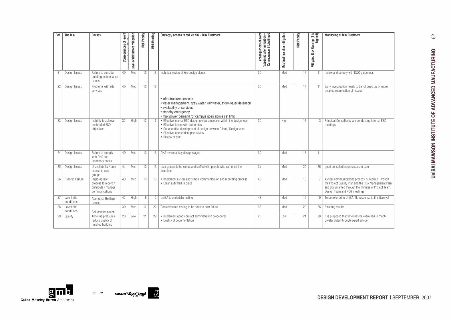
DESIGN DEVELOPMENT REPORT | SEPTEMBER 2007
UniS
A| M
AWSO
N IN
STIT
UTE
OF A
DVAN
CED
MAU
FACT
URIN
G
52
UniS
A| M
AWSO
N IN
STIT
UTE
OF A
DVAN
CED
MAU
FACT
URIN
G
���������������� �������������������������������� ������������������������
����������� ���������
����������� ���������
����������� ���������
����������� ���������
������������� ����������� ��
������������� ����������� ��
������������� ����������� ��
������������� ����������� ���� ��
������ ��������� ����������� �
������ ��������� ����������� �
������ ��������� ����������� �
������ ��������� ����������� � �� ��
������� ����
������� ����
������� ����
������� ������ ��
����������
����������
����������
������������ ��
��������������� ���� ��������������������������� ���� ��������������������������� ���� ��������������������������� ���� ����������������������������������������������������������������������������
� ����������� ��������
� ����������� ��������
� ����������� ��������
� ����������� ��������
������������������������ ��
������������������������ ��
������������������������ ��
������������������������ �� �� ��
����������!������� �
����������!������� �
����������!������� �
����������!������� � �� ��
��������������������������� �
��������������������������� �
��������������������������� �
��������������������������� � �� ��
������� ����
������� ����
������� ����
������� ������ ��
"�������������������
"�������������������
"�������������������
"��������������������#$����
�#$����
�#$����
�#$����
�������%
�������%
�������%
�������%�� ��
" ��� ����� ���������������" ��� ����� ���������������" ��� ����� ���������������" ��� ����� �������������������
*$� 0������'������ 3�������� �� �������
���������������������
�������
50� "��� $(� $(� ���������������-��������������������� (0� "��� $+� $$� �����-������ �����-����0!������������
**� 0������'������ �� ������-���������
���������
50� "��� $(� $(�
• infrastructure services • water management, grey water, rainwater, stormwater detention • availability of services • standby emergency • max power demand for campus goes above set limit
(0� "��� $+� $$� 8���������������� ��������� ����� �� -���������� ���
����������/������� �� ����������
*(� 0������'������ '���������� ���������
������������8�0�
�C��������
(� )���� $*� +� ,�8������������������8�0�������������-��� �������-����������������������
,�8�������������� ��-�������� �������
,� ���� ������������ ������ ������������-������������0�����������
,�8�������������������������������-�
,������-� ��������
(� )���� $*� (� ���������� ���������������� ������������������8�0�
���������
*5� 0������'������ 3�������� �� �����
-����&)������
��� ��� ���� ����
50� "��� $(� $(� &)�������-��������������������� (0� "��� $+� $$� ��
*7� 0������'������ 9����������������� ��
�������� ������
�� ����
5�� "��� $(� $(� 9������ ����� �����������������������-������ ����-� ��������������
����������
(�� "��� *E� *;� � ��� �������� ���� �������� ������
*;� �� �����3������� '����� �������
�� ������ ���� �����
��������������������
� ��������� ���
50� "��� $(� $(� ,�'����������������������������� ��������� ��������� �������� �����
,���������������������������
50� "��� $(� +� .�������� ��������� ����� ��������������������� ����
������ C����A������������������������"���������������
����� ������������ ���������������� ���� C��������4�
0����������������F����������
*+� ������������
� ����� ���.� ��������)��������
�������
5� )���� 6� *� 9���.�� ������������������ 58� "��� $;� D� � �������������� �9���.2�G ����� ����� ���������������
*6� ������������
� ����� ��� � ���� ��������� ��
(0� "��� $+� **� ��������� ����������� ����� ������������������ (8� "��� *E� *;� .-���������������
*D� A������� �������������������
��������������� ��
������������������
*0� � -� *$� *D� ,�'���������� ��� ������������������� ���� ��������
,�A������� ��� ��������� ��
*0� � -� *$� *6� '������� � �����������������������/���������������
������������������ �����/�������������
DESIGN DEVELOPMENT REPORT | SEPTEMBER 2007
APPENDIX C: EXTERNAL SAMPLE BOARD
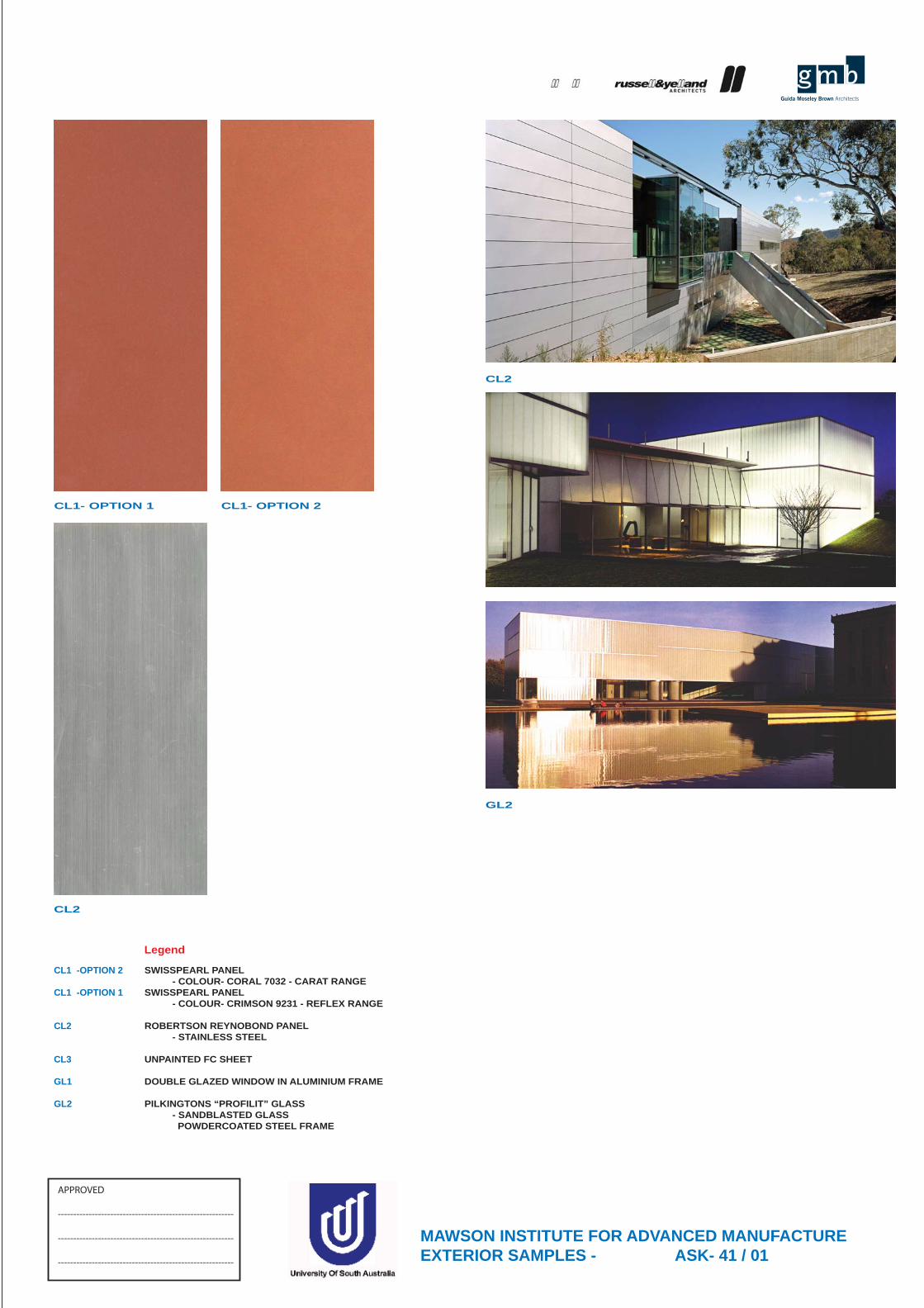
GL2
MAWSON INSTITUTE FOR ADVANCED MANUFACTUREEXTERIOR SAMPLES - ASK- 41 / 01
Legend
SWISSPEARL PANEL - COLOUR- CORAL 7032 - CARAT RANGESWISSPEARL PANEL - COLOUR- CRIMSON 9231 - REFLEX RANGE
ROBERTSON REYNOBOND PANEL - STAINLESS STEEL
UNPAINTED FC SHEET
DOUBLE GLAZED WINDOW IN ALUMINIUM FRAME
PILKINGTONS “PROFILIT” GLASS - SANDBLASTED GLASS POWDERCOATED STEEL FRAME
CL1 -OPTION 2
CL1 -OPTION 1
CL2
CL3
GL1
GL2
APPROVED
---------------------------------------------------------
---------------------------------------------------------
---------------------------------------------------------
CL1- OPTION 1
CL2
CL1- OPTION 2
CL2
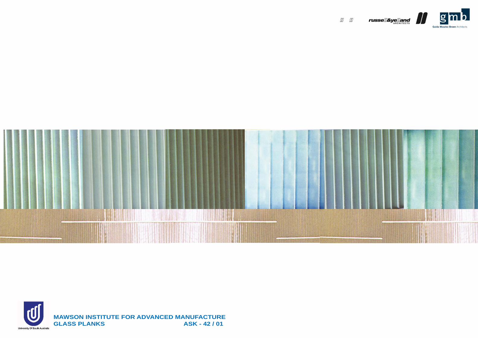
MAWSON INSTITUTE FOR ADVANCED MANUFACTURE GLASS PLANKS ASK - 42 / 01
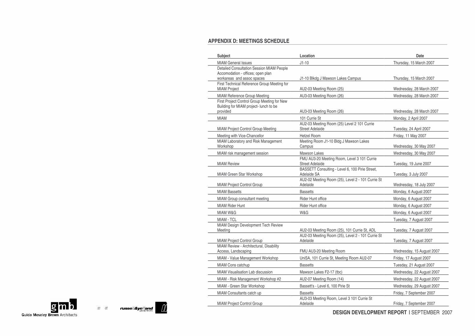
DESIGN DEVELOPMENT REPORT | SEPTEMBER 2007
APPENDIX D: MEETINGS SCHEDULE
Subject Location Date MIAM General Issues J1-10 Thursday, 15 March 2007 Detailed Consultation Session MIAM People Accomodation - offices; open plan workareas and assoc spaces J1-10 Blkdg J Mawson Lakes Campus Thursday, 15 March 2007 First Technical Reference Group Meeting for MIAM Project AU2-03 Meeting Room (25) Wednesday, 28 March 2007
MIAM Reference Group Meeting AU3-03 Meeting Room (26) Wednesday, 28 March 2007 First Project Control Group Meeting for New Building for MIAM project- lunch to be provided AU3-03 Meeting Room (26) Wednesday, 28 March 2007
MIAM 101 Currie St Monday, 2 April 2007
MIAM Project Control Group Meeting AU2-03 Meeting Room (25) Level 2 101 Currie Street Adelaide Tuesday, 24 April 2007
Meeting with Vice-Chancellor Hetzel Room Friday, 11 May 2007 MIAM Laboratory and Risk Management Workshop
Meeting Room J1-10 Bldg J Mawson Lakes Campus Wednesday, 30 May 2007
MIAM risk management session Mawson Lakes Wednesday, 30 May 2007
MIAM Review FMU AU3-20 Meeting Room, Level 3 101 Currie Street Adelaide Tuesday, 19 June 2007
MIAM Green Star Workshop BASSETT Consulting - Level 6, 100 Pirie Street, Adelaide SA Tuesday, 3 July 2007
MIAM Project Control Group AU2-02 Meeting Room (25), Level 2 - 101 Currie St Adelaide Wednesday, 18 July 2007
MIAM Bassetts Bassetts Monday, 6 August 2007
MIAM Group consultant meeting Rider Hunt office Monday, 6 August 2007
MIAM Rider Hunt Rider Hunt office Monday, 6 August 2007
MIAM W&G W&G Monday, 6 August 2007
MIAM - TCL Tuesday, 7 August 2007 MIAM Design Development Tech Review Meeting AU2-03 Meeting Room (25), 101 Currie St, ADL Tuesday, 7 August 2007
MIAM Project Control Group AU2-03 Meeting Room (25), Level 2 - 101 Currie St Adelaide Tuesday, 7 August 2007
MIAM Review - Architectural, Disability Access, Landscaping FMU AU3-20 Meeting Room Wednesday, 15 August 2007
MIAM - Value Management Workshop UniSA, 101 Currie St, Meeting Room AU2-07 Friday, 17 August 2007
MIAM Cons catchup Bassetts Tuesday, 21 August 2007
MIAM Visualisation Lab discussion Mawson Lakes F2-17 (tbc) Wednesday, 22 August 2007
MIAM - Risk Management Workshop #2 AU2-07 Meeting Room (14) Wednesday, 22 August 2007
MIAM - Green Star Workshop Bassett's - Level 6, 100 Pirie St Wednesday, 29 August 2007
MIAM Consultants catch up Bassetts Friday, 7 September 2007
MIAM Project Control Group AU3-03 Meeting Room, Level 3 101 Currie St Adelaide Friday, 7 September 2007
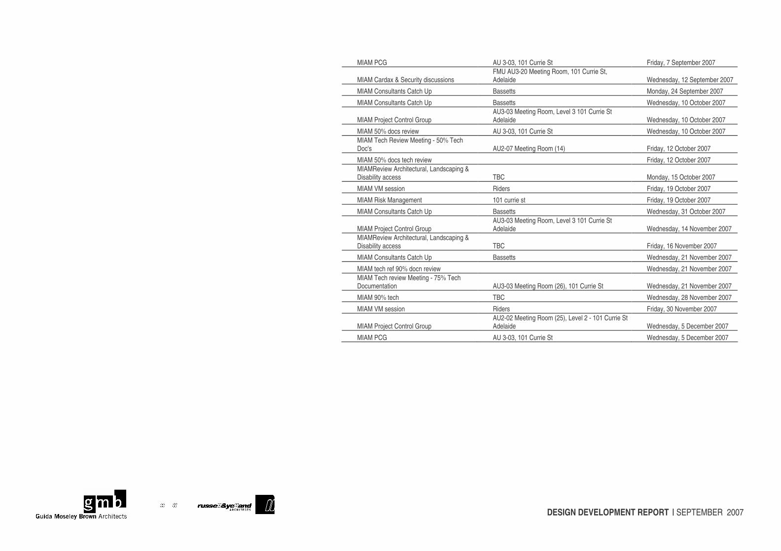
DESIGN DEVELOPMENT REPORT | SEPTEMBER 2007
MIAM PCG AU 3-03, 101 Currie St Friday, 7 September 2007
MIAM Cardax & Security discussions FMU AU3-20 Meeting Room, 101 Currie St, Adelaide Wednesday, 12 September 2007
MIAM Consultants Catch Up Bassetts Monday, 24 September 2007
MIAM Consultants Catch Up Bassetts Wednesday, 10 October 2007
MIAM Project Control Group AU3-03 Meeting Room, Level 3 101 Currie St Adelaide Wednesday, 10 October 2007
MIAM 50% docs review AU 3-03, 101 Currie St Wednesday, 10 October 2007 MIAM Tech Review Meeting - 50% Tech Doc's AU2-07 Meeting Room (14) Friday, 12 October 2007
MIAM 50% docs tech review Friday, 12 October 2007 MIAMReview Architectural, Landscaping & Disability access TBC Monday, 15 October 2007
MIAM VM session Riders Friday, 19 October 2007
MIAM Risk Management 101 currie st Friday, 19 October 2007
MIAM Consultants Catch Up Bassetts Wednesday, 31 October 2007
MIAM Project Control Group AU3-03 Meeting Room, Level 3 101 Currie St Adelaide Wednesday, 14 November 2007
MIAMReview Architectural, Landscaping & Disability access TBC Friday, 16 November 2007
MIAM Consultants Catch Up Bassetts Wednesday, 21 November 2007
MIAM tech ref 90% docn review Wednesday, 21 November 2007 MIAM Tech review Meeting - 75% Tech Documentation AU3-03 Meeting Room (26), 101 Currie St Wednesday, 21 November 2007
MIAM 90% tech TBC Wednesday, 28 November 2007
MIAM VM session Riders Friday, 30 November 2007
MIAM Project Control Group AU2-02 Meeting Room (25), Level 2 - 101 Currie St Adelaide Wednesday, 5 December 2007
MIAM PCG AU 3-03, 101 Currie St Wednesday, 5 December 2007
DESIGN DEVELOPMENT REPORT | SEPTEMBER 2007
APPENDIX E: PROGRAM
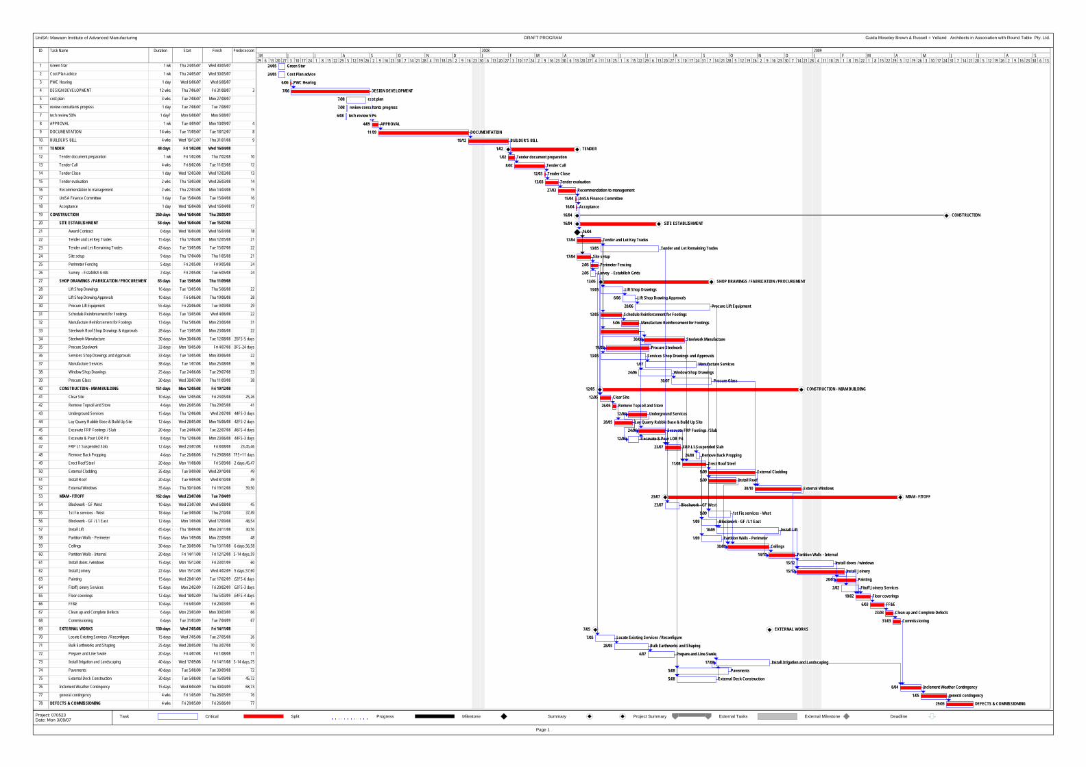
ID Task Name Duration Start Finish Predecessors
1 Green Star 1 wk Thu 24/05/07 Wed 30/05/07
2 Cost Plan advice 1 wk Thu 24/05/07 Wed 30/05/07
3 PWC Hearing 1 day Wed 6/06/07 Wed 6/06/07
4 DESIGN DEVELOPMENT 12 wks Thu 7/06/07 Fri 31/08/07 3
5 cost plan 3 wks Tue 7/08/07 Mon 27/08/07
6 review consultants progress 1 day Tue 7/08/07 Tue 7/08/07
7 tech review 50% 1 day? Mon 6/08/07 Mon 6/08/07
8 APPROVAL 1 wk Tue 4/09/07 Mon 10/09/07 4
9 DOCUMENTATION 14 wks Tue 11/09/07 Tue 18/12/07 8
10 BUILDER'S BILL 4 wks Wed 19/12/07 Thu 31/01/08 9
11 TENDER 48 days Fri 1/02/08 Wed 16/04/08
12 Tender document preparation 1 wk Fri 1/02/08 Thu 7/02/08 10
13 Tender Call 4 wks Fri 8/02/08 Tue 11/03/08 12
14 Tender Close 1 day Wed 12/03/08 Wed 12/03/08 13
15 Tender evaluation 2 wks Thu 13/03/08 Wed 26/03/08 14
16 Recommendation to management 2 wks Thu 27/03/08 Mon 14/04/08 15
17 UniSA Finance Committee 1 day Tue 15/04/08 Tue 15/04/08 16
18 Acceptance 1 day Wed 16/04/08 Wed 16/04/08 17
19 CONSTRUCTION 260 days Wed 16/04/08 Thu 28/05/09
20 SITE ESTABLISHMENT 58 days Wed 16/04/08 Tue 15/07/08
21 Award Contract 0 days Wed 16/04/08 Wed 16/04/08 18
22 Tender and Let Key Trades 15 days Thu 17/04/08 Mon 12/05/08 21
23 Tender and Let Remaining Trades 43 days Tue 13/05/08 Tue 15/07/08 22
24 Site setup 9 days Thu 17/04/08 Thu 1/05/08 21
25 Perimeter Fencing 5 days Fri 2/05/08 Fri 9/05/08 24
26 Survey - Estabilish Grids 2 days Fri 2/05/08 Tue 6/05/08 24
27 SHOP DRAWINGS / FABRICATION / PROCUREMENT 83 days Tue 13/05/08 Thu 11/09/08
28 Lift Shop Drawings 16 days Tue 13/05/08 Thu 5/06/08 22
29 Lift Shop Drawing Approvals 10 days Fri 6/06/08 Thu 19/06/08 28
30 Procure Lift Equipment 55 days Fri 20/06/08 Tue 9/09/08 29
31 Schedule Reinforcement for Footings 15 days Tue 13/05/08 Wed 4/06/08 22
32 Manufacture Reinforcement for Footings 13 days Thu 5/06/08 Mon 23/06/08 31
33 Steelwork Roof Shop Drawings & Approvals 28 days Tue 13/05/08 Mon 23/06/08 22
34 Steelwork Manufacture 30 days Mon 30/06/08 Tue 12/08/08 ,35FS-5 days
35 Procure Steelwork 33 days Mon 19/05/08 Fri 4/07/08 33FS-24 days
36 Services Shop Drawings and Approvals 33 days Tue 13/05/08 Mon 30/06/08 22
37 Manufacture Services 38 days Tue 1/07/08 Mon 25/08/08 36
38 Window Shop Drawings 25 days Tue 24/06/08 Tue 29/07/08 33
39 Procure Glass 30 days Wed 30/07/08 Thu 11/09/08 38
40 CONSTRUCTION - MIAM BUILDING 151 days Mon 12/05/08 Fri 19/12/08
41 Clear Site 10 days Mon 12/05/08 Fri 23/05/08 25,26
42 Remove Topsoil and Store 4 days Mon 26/05/08 Thu 29/05/08 41
43 Underground Services 15 days Thu 12/06/08 Wed 2/07/08 44FS-3 days
44 Lay Quarry Rubble Base & Build Up Site 12 days Wed 28/05/08 Mon 16/06/08 42FS-2 days
45 Excavate FRP Footings / Slab 20 days Tue 24/06/08 Tue 22/07/08 ,46FS-4 days
46 Excavate & Pour LOR Pit 8 days Thu 12/06/08 Mon 23/06/08 44FS-3 days
47 FRP L1 Suspended Slab 12 days Wed 23/07/08 Fri 8/08/08 23,45,46
48 Remove Back Propping 4 days Tue 26/08/08 Fri 29/08/08 7FS+11 days
49 Erect Roof Steel 20 days Mon 11/08/08 Fri 5/09/08 -2 days,45,47
50 External Cladding 35 days Tue 9/09/08 Wed 29/10/08 49
51 Install Roof 20 days Tue 9/09/08 Wed 8/10/08 49
52 External Windows 35 days Thu 30/10/08 Fri 19/12/08 39,50
53 MIAM - FITOFF 162 days Wed 23/07/08 Tue 7/04/09
54 Blockwork - GF West 10 days Wed 23/07/08 Wed 6/08/08 45
55 1st Fix services - West 18 days Tue 9/09/08 Thu 2/10/08 37,49
56 Blockwork - GF / L1 East 12 days Mon 1/09/08 Wed 17/09/08 48,54
57 Install Lift 45 days Thu 18/09/08 Mon 24/11/08 30,56
58 Partition Walls - Perimeter 15 days Mon 1/09/08 Mon 22/09/08 48
59 Ceilings 30 days Tue 30/09/08 Thu 13/11/08 -6 days,56,58
60 Partition Walls - Internal 20 days Fri 14/11/08 Fri 12/12/08 S-14 days,59
61 Install doors / windows 15 days Mon 15/12/08 Fri 23/01/09 60
62 Install Joinery 22 days Mon 15/12/08 Wed 4/02/09 -5 days,57,60
63 Painting 15 days Wed 28/01/09 Tue 17/02/09 ,62FS-6 days
64 Fitoff Joinery Services 15 days Mon 2/02/09 Fri 20/02/09 62FS-3 days
65 Floor coverings 12 days Wed 18/02/09 Thu 5/03/09 ,64FS-4 days
66 FF&E 10 days Fri 6/03/09 Fri 20/03/09 65
67 Clean up and Complete Defects 6 days Mon 23/03/09 Mon 30/03/09 66
68 Commissioning 6 days Tue 31/03/09 Tue 7/04/09 67
69 EXTERNAL WORKS 130 days Wed 7/05/08 Fri 14/11/08
70 Locate Existing Services / Reconfigure 15 days Wed 7/05/08 Tue 27/05/08 26
71 Bulk Earthworks and Shaping 25 days Wed 28/05/08 Thu 3/07/08 70
72 Prepare and Line Swale 20 days Fri 4/07/08 Fri 1/08/08 71
73 Install Irrigation and Landscaping 40 days Wed 17/09/08 Fri 14/11/08 S-14 days,75
74 Pavements 40 days Tue 5/08/08 Tue 30/09/08 72
75 External Deck Construction 30 days Tue 5/08/08 Tue 16/09/08 45,72
76 Inclement Weather Contingency 15 days Wed 8/04/09 Thu 30/04/09 68,73
77 general contingency 4 wks Fri 1/05/09 Thu 28/05/09 76
78 DEFECTS & COMMISSIONING 4 wks Fri 29/05/09 Fri 26/06/09 77
24/05 Green Star
24/05 Cost Plan advice
6/06 PWC Hearing
7/06 DESIGN DEVELOPMENT
7/08 cost plan
7/08 review consultants progress
6/08 tech review 50%
4/09 APPROVAL
11/09 DOCUMENTATION
19/12 BUILDER'S BILL
1/02 TENDER
1/02 Tender document preparation
8/02 Tender Call
12/03 Tender Close
13/03 Tender evaluation
27/03 Recommendation to management
15/04 UniSA Finance Committee
16/04 Acceptance
16/04 CONSTRUCTION
16/04 SITE ESTABLISHMENT
16/04
17/04 Tender and Let Key Trades
13/05 Tender and Let Remaining Trades
17/04 Site setup
2/05 Perimeter Fencing
2/05 Survey - Estabilish Grids
13/05 SHOP DRAWINGS / FABRICATION / PROCUREMENT
13/05 Lift Shop Drawings
6/06 Lift Shop Drawing Approvals
20/06 Procure Lift Equipment
13/05 Schedule Reinforcement for Footings
5/06 Manufacture Reinforcement for Footings
30/06 Steelwork Manufacture
19/05 Procure Steelwork
13/05 Services Shop Drawings and Approvals
1/07 Manufacture Services
24/06 Window Shop Drawings
30/07 Procure Glass
12/05 CONSTRUCTION - MIAM BUILDING
12/05 Clear Site
26/05 Remove Topsoil and Store
12/06 Underground Services
28/05 Lay Quarry Rubble Base & Build Up Site
24/06 Excavate FRP Footings / Slab
12/06 Excavate & Pour LOR Pit
23/07 FRP L1 Suspended Slab
26/08 Remove Back Propping
11/08 Erect Roof Steel
9/09 External Cladding
9/09 Install Roof
30/10 External Windows
23/07 MIAM - FITOFF
23/07 Blockwork - GF West
9/09 1st Fix services - West
1/09 Blockwork - GF / L1 East
18/09 Install Lift
1/09 Partition Walls - Perimeter
30/09 Ceilings
14/11 Partition Walls - Internal
15/12 Install doors / windows
15/12 Install Joinery
28/01 Painting
2/02 Fitoff Joinery Services
18/02 Floor coverings
6/03 FF&E
23/03 Clean up and Complete Defects
31/03 Commissioning
7/05 EXTERNAL WORKS
7/05 Locate Existing Services / Reconfigure
28/05 Bulk Earthworks and Shaping
4/07 Prepare and Line Swale
17/09 Install Irrigation and Landscaping
5/08 Pavements
5/08 External Deck Construction
8/04 Inclement Weather Contingency
1/05 general contingency
29/05 DEFECTS & COMMISSIONING
29 6 13 20 27 3 10 17 24 1 8 15 22 29 5 12 19 26 2 9 16 23 30 7 14 21 28 4 11 18 25 2 9 16 23 30 6 13 20 27 3 10 17 24 2 9 16 23 30 6 13 20 27 4 11 18 25 1 8 15 22 29 6 13 20 27 3 10 17 24 31 7 14 21 28 5 12 19 26 2 9 16 23 30 7 14 21 28 4 11 18 25 1 8 15 22 1 8 15 22 29 5 12 19 26 3 10 17 24 31 7 14 21 28 5 12 19 26 2 9 16 23 30 6 13M J J A S O N D J F M A M J J A S O N D J F M A M J J A S
2008 2009
Task Critical Split Progress Milestone Summary Project Summary External Tasks External Milestone Deadline
UniSA: Mawaon Institute of Advanced Manufacturing DRAFT PROGRAM Guida Moseley Brown & Russell + Yelland Architects in Association with Round Table Pty. Ltd.
Page 1
Project: 070523Date: Mon 3/09/07
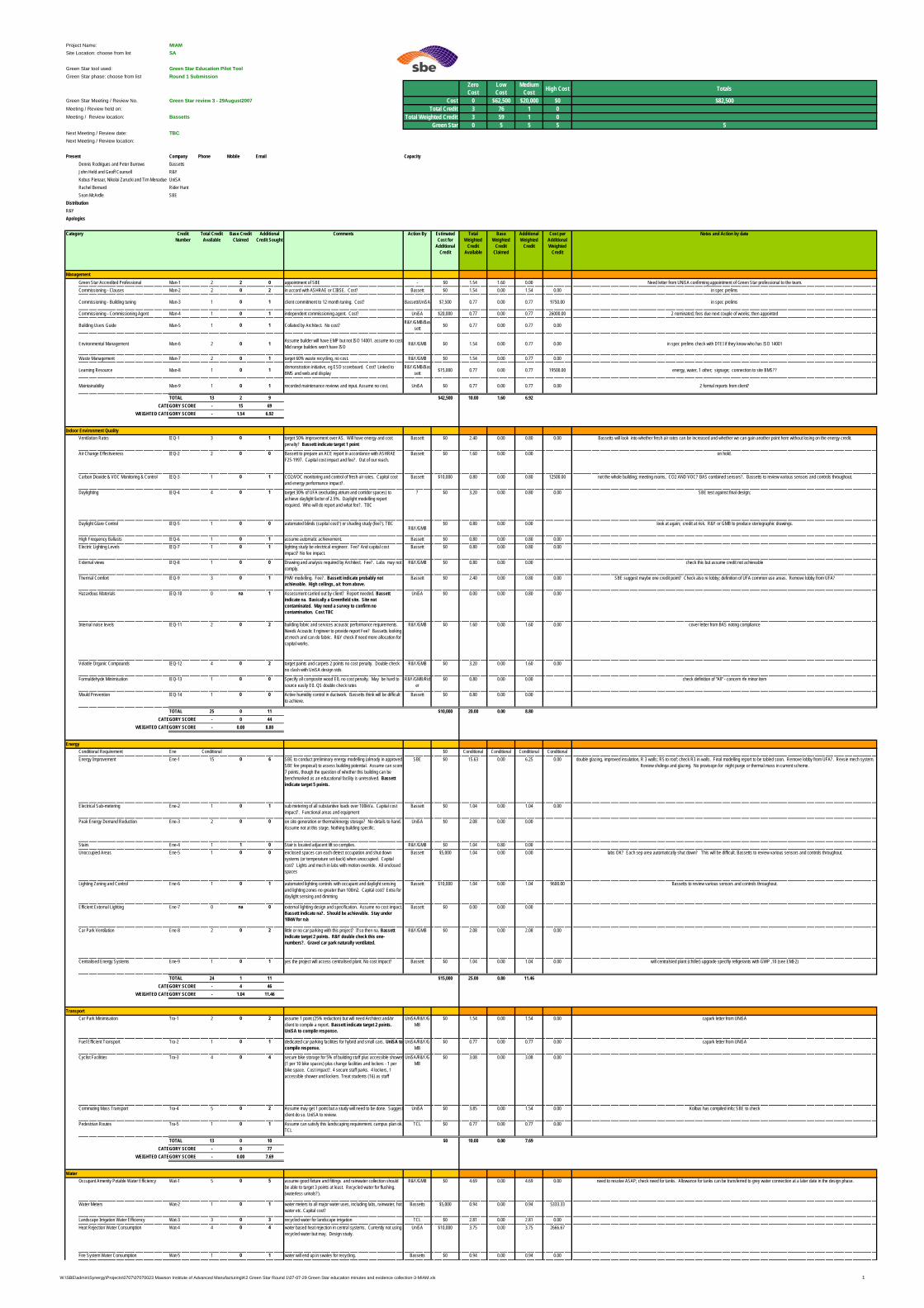
Project Name: MIAMSite Location: choose from list SA
Green Star tool used: Green Star Education Pilot ToolGreen Star phase: choose from list Round 1 Submission
ZeroCost
LowCost
Medium Cost High Cost Totals
Green Star Meeting / Review No. Green Star review 3 - 29August2007 Cost 0 $62,500 $20,000 $0 $82,500Meeting / Review held on: Total Credit 3 76 1 0Meeting / Review location: Bassetts Total Weighted Credit 3 59 1 0
Green Star 0 5 5 5 5Next Meeting / Review date: TBCNext Meeting / Review location:
Present Company Phone Mobile Email CapacityDennis Rodrigues and Peter Burrows BassettsJohn Held and Geoff Counsell R&YKobus Pienaar, Nikolai Zarucki and Tim Menadue UniSARachel Bernard Rider HuntSean McArdle SBE
DistributionR&YApologies
Category Credit Number
Total Credit Available
Base Credit Claimed
Additional Credit Sought
Comments Action By Estimated Cost for
Additional Credit
Total Weighted
Credit Available
Base Weighted
Credit Claimed
Additional Weighted
Credit
Cost per Additional Weighted
Credit
Notes and Action by date
ManagementGreen Star Accredited Professional Man-1 2 2 0 appointment of SBE - $0 1.54 1.60 0.00 Need letter from UNiSA confirming appointment of Green Star professional to the team.Commissioning - Clauses Man-2 2 0 2 in accord with ASHRAE or CIBSE. Cost? Bassett $0 1.54 0.00 1.54 0.00 in spec prelims
Commissioning - Building tuning Man-3 1 0 1 client commitment to 12 month tuning. Cost? Bassett/UniSA $7,500 0.77 0.00 0.77 9750.00 in spec prelims
Commissioning - Commissioning Agent Man-4 1 0 1 independent commissioning agent. Cost? UniSA $20,000 0.77 0.00 0.77 26000.00 2 nominated; fees due next couple of weeks; then appointed
Building Users Guide Man-5 1 0 1 Collated by Architect. No cost? R&Y/GMB/Bassett $0 0.77 0.00 0.77 0.00
Environmental Management Man-6 2 0 1 Assume builder will have EMP but not ISO 14001. assume no cost.Mid range builders won't have ISO R&Y/GMB $0 1.54 0.00 0.77 0.00 in spec prelims check with DTEI if they know who has ISO 14001
Waste Management Man-7 2 0 1 target 60% waste recycling, no cost. R&Y/GMB $0 1.54 0.00 0.77 0.00
Learning Resource Man-8 1 0 1 demonstration initiative, eg ESD scoreboard. Cost? Linked to BMS and web and display
R&Y/GMB/Bassett $15,000 0.77 0.00 0.77 19500.00 energy, water, 1 other; signage; connection to site BMS??
Maintainability Man-9 1 0 1 recorded maintenance reviews and input. Assume no cost. UniSA $0 0.77 0.00 0.77 0.00 2 formal reports from client?
TOTAL 13 2 9 $42,500 10.00 1.60 6.92CATEGORY SCORE - 15 69
WEIGHTED CATEGORY SCORE - 1.54 6.92
Indoor Environment QualityVentilation Rates IEQ-1 3 0 1 target 50% improvement over AS. Will have energy and cost
penalty? Bassett indicate target 1 pointBassett $0 2.40 0.00 0.80 0.00 Bassetts will look into whether fresh air rates can be increased and whether we can gain another point here without losing on the energy credit.
Air Change Effectiveness IEQ-2 2 0 0 Bassett to prepare an ACE report in accordance with ASHRAE F25-1997. Capital cost impact and fee?. Out of our reach.
Bassett $0 1.60 0.00 0.00 on hold.
Carbon Dioxide & VOC Monitoring & Control IEQ-3 1 0 1 CO2/VOC monitoring and control of fresh air rates. Capital cost and energy performance impact?.
Bassett $10,000 0.80 0.00 0.80 12500.00 not the whole building; meeting rooms, CO2 AND VOC? BAS combined sensors?. Bassetts to review various sensors and controls throughout.
Daylighting IEQ-4 4 0 1 target 30% of UFA (excluding atrium and corridor spaces) to achieve daylight factor of 2.5%. Daylight modelling report required. Who will do report and what fee?. TBC
? $0 3.20 0.00 0.80 0.00 SBE test against final design;
Daylight Glare Control IEQ-5 1 0 0 automated blinds (capital cost?) or shading study (fee?). TBCR&Y/GMB
$0 0.80 0.00 0.00 look at again; credit at risk. R&Y or GMB to produce steriographic drawings.
High Frequency Ballasts IEQ-6 1 0 1 assume automatic achievement. Bassett $0 0.80 0.00 0.80 0.00Electric Lighting Levels IEQ-7 1 0 1 lighting study be electrical engineer. Fee? And capital cost
impact? No fee impact.Bassett $0 0.80 0.00 0.80 0.00
External views IEQ-8 1 0 0 Drawing and analysis required by Architect. Fee?. Labs may not comply.
R&Y/GMB $0 0.80 0.00 0.00 check this but assume credit not achievable
Thermal Comfort IEQ-9 3 0 1 PMV modelling. Fee?. Bassett indicate probably not achievable. High ceilings, a/c from above.
Bassett $0 2.40 0.00 0.80 0.00 SBE suggest maybe one credit point? Check also re lobby; definition of UFA common use areas. Remove lobby from UFA?
Hazardous Materials IEQ-10 0 na 1 Assessment carried out by client? Report needed. Bassett indicate na. Basically a Greenfield site. Site not contaminated. May need a survey to confirm no contamination. Cost TBC
UniSA $0 0.00 0.00 0.80 0.00
Internal noise levels IEQ-11 2 0 2 building fabric and services acoustic performance requirements. Needs Acoustic Engineer to provide report Fee? Bassetts looking at mech and can do fabric. R&Y check if need more allocation for capital works.
R&Y/GMB $0 1.60 0.00 1.60 0.00 cover letter from BAS noting compliance
Volatile Organic Compounds IEQ-12 4 0 2 target paints and carpets 2 points no cost penalty. Double check no clash with UniSA design stds
R&Y/GMB $0 3.20 0.00 1.60 0.00
Formaldehyde Minimisation IEQ-13 1 0 0 Specify all composite wood E0, no cost penalty. May be hard to source easily E0. QS double check rates
R&Y/GMB/Rider
$0 0.80 0.00 0.00 check definition of "All" - concern rfe minor item
Mould Prevention IEQ-14 1 0 0 Active humidity control in ductwork. Bassetts think will be difficult to achieve.
Bassett $0 0.80 0.00 0.00
TOTAL 25 0 11 $10,000 20.00 0.00 8.80CATEGORY SCORE - 0 44
WEIGHTED CATEGORY SCORE - 0.00 8.80
EnergyConditional Requirement Ene Conditional $0 Conditional Conditional Conditional ConditionalEnergy Improvement Ene-1 15 0 6 SBE to conduct preliminary energy modelling (already in approved
SBE fee proposal) to assess building potential. Assume can score 7 points, though the question of whether this building can be benchmarked as an educational facility is unresolved. Bassett indicate target 5 points.
SBE $0 15.63 0.00 6.25 0.00 double glazing, improved insulation, R 3 walls; R5 to roof; check R3 in walls. Final modelling report to be tabled soon. Remove lobby from UFA?. Revsie mech system. Review shdinga and glazing. No provisopn for night purge or thermal mass in current scheme.
Electrical Sub-metering Ene-2 1 0 1 sub metering of all substantive loads over 100kVa. Capital cost impact?. Functional areas and equipment
Bassett $0 1.04 0.00 1.04 0.00
Peak Energy Demand Reduction Ene-3 2 0 0 on site generation or thermal/energy storage? No details to hand. Assume not at this stage. Nothing building specific.
UniSA $0 2.08 0.00 0.00
Stairs Ene-4 1 1 0 Stair is located adjacent lift so complies. R&Y/GMB $0 1.04 0.80 0.00Unoccupied Areas Ene-5 1 0 0 enclosed spaces can each detect occupation and shut down
systems (or temperature set-back) when unoccupied. Capital cost? Lights and mech in labs with motion override. All enclosed spaces
Bassett $5,000 1.04 0.00 0.00 labs OK? Each sep area automatically shut down? This will be difficult. Bassetts to review various sensors and controls throughout.
Lighting Zoning and Control Ene-6 1 0 1 automated lighting controls with occupant and daylight sensing and lighting zones no greater than 100m2. Capital cost? Extra for daylight sensing and dimming
Bassett $10,000 1.04 0.00 1.04 9600.00 Bassetts to review various sensors and controls throughout.
Efficient External Lighting Ene-7 0 na 0 external lighting design and specification. Assume no cost impact. Bassett indicate na?. Should be achievable. Stay under 10kW for n/a
Bassett $0 0.00 0.00 0.00
Car Park Ventilation Ene-8 2 0 2 little or no car parking with this project? If so then na. Bassett indicate target 2 points. R&Y double check this one-numbers?. Gravel car park naturally ventilated.
R&Y/GMB $0 2.08 0.00 2.08 0.00
Centralised Energy Systems Ene-9 1 0 1 yes the project will access centralised plant. No cost impact? Bassett $0 1.04 0.00 1.04 0.00 will centralsied plant (chiller) upgrade specifiy refigerants with GWP ,10 (see EMI-2)
TOTAL 24 1 11 $15,000 25.00 0.80 11.46CATEGORY SCORE - 4 46
WEIGHTED CATEGORY SCORE - 1.04 11.46
TransportCar Park Minimisation Tra-1 2 0 2 assume 1 point (25% reduction) but will need Architect and/or
client to compile a report. Bassett indicate target 2 points. UniSA to compile response.
UniSA/R&Y/GMB
$0 1.54 0.00 1.54 0.00 capark letter from UNiSA
Fuel Efficient Transport Tra-2 1 0 1 dedicated car parking facilities for hybrid and small cars. UniSA to compile response.
UniSA/R&Y/GMB
$0 0.77 0.00 0.77 0.00 capark letter from UNiSA
Cyclist Facilities Tra-3 4 0 4 secure bike storage for 5% of building staff plus accessible shower (1 per 10 bike spaces) plus change facilities and lockers - 1 per bike space. Cost impact?. 4 secure staff parks. 4 lockers, 1 accessible shower and lockers. Treat students (16) as staff
UniSA/R&Y/GMB
$0 3.08 0.00 3.08 0.00
Commuting Mass Transport Tra-4 5 0 2 Assume may get 1 point but a study will need to be done. Suggestclient do so. UniSA to review.
UniSA $0 3.85 0.00 1.54 0.00 Kolbus has compiled info; SBE to check
Pedestrian Routes Tra-5 1 0 1 Assume can satisfy this landscaping requirement. campus plan ok. TCL
TCL $0 0.77 0.00 0.77 0.00
TOTAL 13 0 10 $0 10.00 0.00 7.69CATEGORY SCORE - 0 77
WEIGHTED CATEGORY SCORE - 0.00 7.69
WaterOccupant Amenity Potable Water Efficiency Wat-1 5 0 5 assume good fixture and fittings and rainwater collection should
be able to target 3 points at least. Recycled water for flushing. (waterless urinals?).
R&Y/GMB $0 4.69 0.00 4.69 0.00 need to resolve ASAP; check need for tanks. Allowance for tanks can be transferred to grey water connection at a later date in the design phase.
Water Meters Wat-2 1 0 1 water meters to all major water uses, including labs, rainwater, hot water etc. Capital cost?
Bassetts $5,000 0.94 0.00 0.94 5333.33
Landscape Irrigation Water Efficiency Wat-3 3 0 3 recycled water for landscape irrigation TCL $0 2.81 0.00 2.81 0.00Heat Rejection Water Consumption Wat-4 4 0 4 water based heat rejection in central systems. Currently not using
recycled water but may. Design study.UniSA $10,000 3.75 0.00 3.75 2666.67
Fire System Water Consumption Wat-5 1 0 1 water will end up in swales for recycling. Bassetts $0 0.94 0.00 0.94 0.00
W:\SBE\admin\Synergy\Projects\0707\07070023 Mawson Institute of Advanced Manufacturing\K2 Green Star Round 1\07-07-29 Green Star education minutes and evidence collection-3-MIAM.xls 1
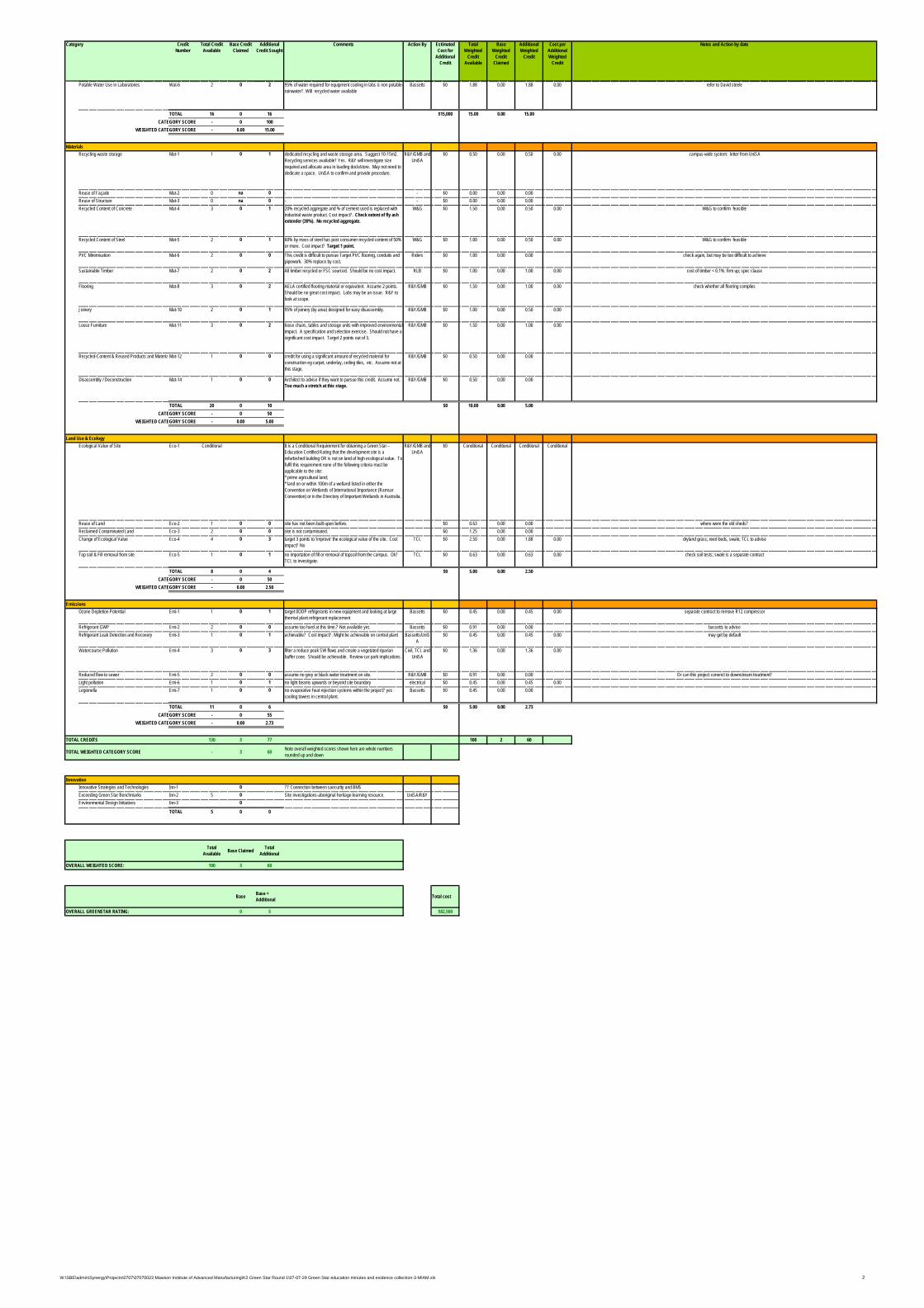
Category Credit Number
Total Credit Available
Base Credit Claimed
Additional Credit Sought
Comments Action By Estimated Cost for
Additional Credit
Total Weighted
Credit Available
Base Weighted
Credit Claimed
Additional Weighted
Credit
Cost per Additional Weighted
Credit
Notes and Action by date
Potable Water Use in Laboratories Wat-6 2 0 2 95% of water required for equipment cooling in labs is non potable-rainwater?. Will recycled water available
Bassetts $0 1.88 0.00 1.88 0.00 refer to David steele
TOTAL 16 0 16 $15,000 15.00 0.00 15.00CATEGORY SCORE - 0 100
WEIGHTED CATEGORY SCORE - 0.00 15.00
MaterialsRecycling waste storage Mat-1 1 0 1 dedicated recycling and waste storage area. Suggest 10-15m2.
Recycling services available? Yes. R&Y will investigate size required and allocate area in loading dock/store. May not need to dedicate a space. UniSA to confirm and provide procedure.
R&Y/GMB and UniSA
$0 0.50 0.00 0.50 0.00 campus-wide system: letter from UniSA
Reuse of Façade Mat-2 0 na 0 - - $0 0.00 0.00 0.00Reuse of Structure Mat-3 0 na 0 - - $0 0.00 0.00 0.00Recycled Content of Concrete Mat-4 3 0 1 20% recycled aggregate and % of cement used is replaced with
industrial waste product. Cost impact?. Check extent of fly ash extender (30%). No recycled aggregate.
W&G $0 1.50 0.00 0.50 0.00 W&G to confirm feasible
Recycled Content of Steel Mat-5 2 0 1 60% by mass of steel has post consumer recycled content of 50% or more. Cost impact? Target 1 point.
W&G $0 1.00 0.00 0.50 0.00 W&G to confirm feasible
PVC Minimisation Mat-6 2 0 0 This credit is difficult to pursue Target PVC flooring, conduits and pipework. 30% replace by cost.
Riders $0 1.00 0.00 0.00 check again, but may be too difficult to achieve
Sustainable Timber Mat-7 2 0 2 All timber recycled or FSC sourced. Should be no cost impact. RLB $0 1.00 0.00 1.00 0.00 cost of timber < 0.1%: firm up; spec clause
Flooring Mat-8 3 0 2 AELA certified flooring material or equivalent. Assume 2 points. Should be no great cost impact. Labs may be an issue. R&Y to look at scope.
R&Y/GMB $0 1.50 0.00 1.00 0.00 check whether all flooring complies
Joinery Mat-10 2 0 1 95% of joinery (by area) designed for easy disassembly. R&Y/GMB $0 1.00 0.00 0.50 0.00
Loose Furniture Mat-11 3 0 2 loose chairs, tables and storage units with improved environmental impact. A specification and selection exercise. Should not have a significant cost impact. Target 2 points out of 3.
R&Y/GMB $0 1.50 0.00 1.00 0.00
Recycled-Content & Reused Products and Materia Mat-12 1 0 0 credit for using a significant amount of recycled material for construction eg carpet, underlay, ceiling tiles, etc. Assume not at this stage.
R&Y/GMB $0 0.50 0.00 0.00
Disassembly / Deconstruction Mat-14 1 0 0 Architect to advise if they want to pursue this credit. Assume not. Too much a stretch at this stage.
R&Y/GMB $0 0.50 0.00 0.00
TOTAL 20 0 10 $0 10.00 0.00 5.00CATEGORY SCORE - 0 50
WEIGHTED CATEGORY SCORE - 0.00 5.00
Land Use & EcologyEcological Value of Site Eco-1 Conditional It is a Conditional Requirement for obtaining a Green Star –
Education Certified Rating that the development site is a refurbished building OR is not on land of high ecological value. To fulfil this requirement none of the following criteria must be applicable to the site:* prime agricultural land;* land on or within 100m of a wetland listed in either the Convention on Wetlands of International Importance (Ramsar Convention) or in the Directory of Important Wetlands in Australia.
R&Y/GMB and UniSA
$0 Conditional Conditional Conditional Conditional
Reuse of Land Eco-2 1 0 0 site has not been built upon before. $0 0.63 0.00 0.00 where were the old sheds?Reclaimed Contaminated Land Eco-3 2 0 0 site is not contaminated. $0 1.25 0.00 0.00Change of Ecological Value Eco-4 4 0 3 target 3 points to 'improve' the ecological value of the site. Cost
impact? NoTCL $0 2.50 0.00 1.88 0.00 dryland grass; reed beds, swale; TCL to advise
Top soil & Fill removal from site Eco-5 1 0 1 no importation of fill or removal of topsoil from the campus. Ok? TCL to investigate.
TCL $0 0.63 0.00 0.63 0.00 check soil tests; swale is a separate contract
TOTAL 8 0 4 $0 5.00 0.00 2.50CATEGORY SCORE - 0 50
WEIGHTED CATEGORY SCORE - 0.00 2.50
EmissionsOzone Depletion Potential Emi-1 1 0 1 target 0ODP refrigerants in new equipment and looking at large
thermal plant refrigerant replacementBassetts $0 0.45 0.00 0.45 0.00 separate contract to remove R12 compressor
Refrigerant GWP Emi-2 2 0 0 assume too hard at this time.? Not available yet. Bassetts $0 0.91 0.00 0.00 bassetts to adviseRefrigerant Leak Detection and Recovery Emi-3 1 0 1 achievable? Cost impact?. Might be achievable on central plant Bassetts/UniS
A$0 0.45 0.00 0.45 0.00 may get by default
Watercourse Pollution Emi-4 3 0 3 filter a reduce peak SW flows and create a vegetated riparian buffer zone. Should be achievable. Review car park implications.
Civil, TCL and UniSA
$0 1.36 0.00 1.36 0.00
Reduced flow to sewer Emi-5 2 0 0 assume no grey or black water treatment on site. R&Y/GMB $0 0.91 0.00 0.00 Or can this project conenct to downstream treatment?Light pollution Emi-6 1 0 1 no light beams upwards or beyond site boundary electrical $0 0.45 0.00 0.45 0.00Legionella Emi-7 1 0 0 no evaporative heat rejection systems within the project? yes
cooling towers in central plant.Bassetts $0 0.45 0.00 0.00
TOTAL 11 0 6 $0 5.00 0.00 2.73CATEGORY SCORE - 0 55
WEIGHTED CATEGORY SCORE - 0.00 2.73
TOTAL CREDITS 130 3 77 100 2 60
TOTAL WEIGHTED CATEGORY SCORE - 3 60 Note overall weighted scores shown here are whole numbers rounded up and down
InnovationInnovative Strategies and Technologies Inn-1 0 ?? Connection between saecurity and BMSExceeding Green Star Benchmarks Inn-2 5 0 Site investigations-aboriginal heritage-learning resource. UniSA/R&YEnvironmental Design Initiatives Inn-3 0
TOTAL 5 0 0
Total Available Base Claimed Total
Additional
OVERALL WEIGHTED SCORE: 100 3 60
Base Base + Additional Total cost
OVERALL GREENSTAR RATING: 0 5 $82,500
W:\SBE\admin\Synergy\Projects\0707\07070023 Mawson Institute of Advanced Manufacturing\K2 Green Star Round 1\07-07-29 Green Star education minutes and evidence collection-3-MIAM.xls 2
DESIGN DEVELOPMENT REPORT | SEPTEMBER 2007
APPENDIX F: GREEN STAR MATRIX
DESIGN DEVELOPMENT REPORT | SEPTEMBER 2007
APPENDIX G: ROOM DATA SHEETS
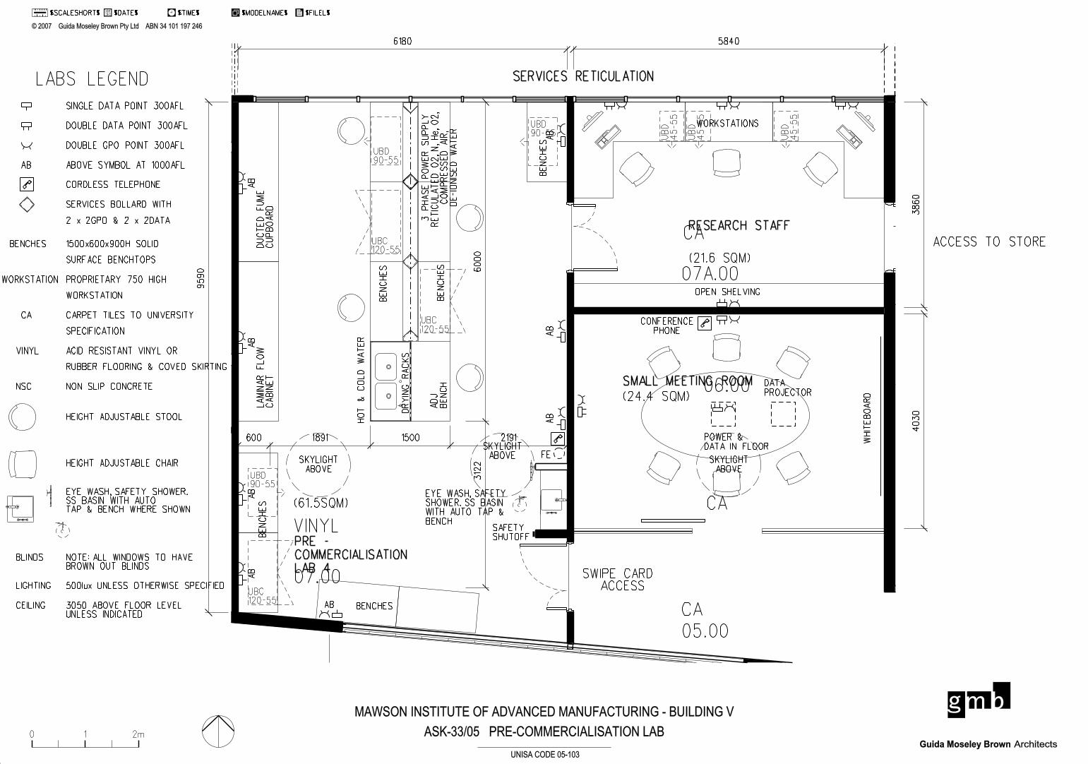
PRE -
COMMERCIALISATION
LAB 4
SMALL MEETING ROOM
SERVICES RETICULATION
RESEARCH STAFF
ACCESS TO STORE
SWIPE CARD ACCESS
(61.5SQM)
(24.4 SQM)
(21.6 SQM)
9590
6180 5840
38
60
403
0
219115001891600
312
26000
ASK-33/05 PRE-COMMERCIALISATION LAB0 1 2m
' 2007 Guida Moseley Brown Pty Ltd ABN 34 101 197 246
ArchitectsGuida Moseley Brown
$DATE$ $TIME$ $MODELNAME$ $FILEL$$SCALESHORT$1 2
UNISA CODE 05-103
MAWSON INSTITUTE OF ADVANCED MANUFACTURING - BUILDING V
VINYL
CA
CA
CA
AB
AB
AB
AB
AB
AB
AB
AB
ADJ
BE
NC
HB
EN
CH
ES
BE
NC
HE
S
BE
NC
HE
S
LA
MIN
AR
FL
OW
CA
BIN
ET
BE
NC
HE
S
BENCHES
EYE WASH, SAFETY
SHOWER. SS BASIN
WITH AUTO TAP &
BENCH
CONFERENCE
PHONE
DATA
PROJECTOR
POWER &
DATA IN FLOOR
WHIT
EB
OA
RD
WORKSTATIONS
OPEN SHELVING
SKYLIGHT
ABOVESKYLIGHT
ABOVE
SKYLIGHT
ABOVE
DR
YIN
G
RA
CK
S
FE
SAFETYSHUTOFF
3
PH
AS
E
PO
WE
R
SU
PP
LY
RE
TIC
UL
AT
ED
O2,
N,
He,
O2,
CO
MP
RE
SS
ED
AIR,
DE-IO
NIS
ED
WA
TE
R
HO
T
&
CO
LD
WA
TE
R
UBC120-55
UBC120-55
UBC120-55
UB
D
45-5
5
UB
D
45-5
5
UB
D
45-5
5
UBD90-55
UBD90-55
UBD90-55
DU
CT
ED
FU
ME
CU
PB
OA
RD
07.00
07A.00
06.00
05.00
SINGLE DATA POINT 300AFL
DOUBLE DATA POINT 300AFL
DOUBLE GPO POINT 300AFL
ABOVE SYMBOL AT 1000AFLAB
CORDLESS TELEPHONE
BENCHES 1500x600x900H SOLID
SURFACE BENCHTOPS
WORKSTATION PROPRIETARY 750 HIGH
WORKSTATION
SERVICES BOLLARD WITH
2 x 2GPO & 2 x 2DATA
CA CARPET TILES TO UNIVERSITY
SPECIFICATION
VINYL
LABS LEGEND
HEIGHT ADJUSTABLE STOOL
HEIGHT ADJUSTABLE CHAIR
EYE WASH, SAFETY SHOWER.SS BASIN WITH AUTO TAP & BENCH WHERE SHOWN
NOTE: ALL WINDOWS TO HAVEBROWN OUT BLINDS
NSC NON SLIP CONCRETE
LIGHTING 500lux UNLESS OTHERWISE SPECIFIED
BLINDS
ACID RESISTANT VINYL OR
RUBBER FLOORING & COVED SKIRTING
CEILING 3050 ABOVE FLOOR LEVELUNLESS INDICATED
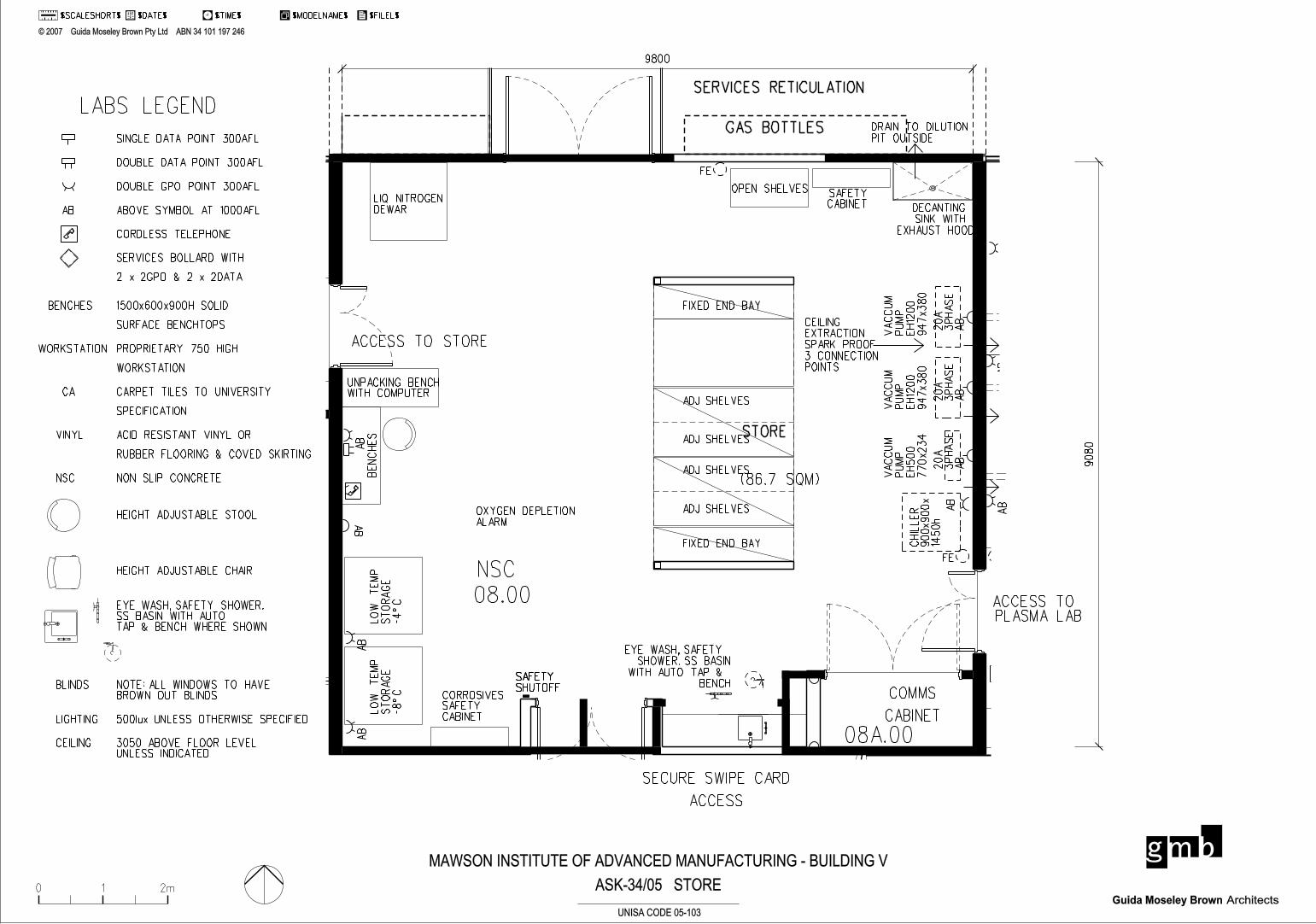
ACCESS TO STORE
STORE
SECURE SWIPE CARD
ACCESS
SERVICES RETICULATION
GAS BOTTLES
COMMS
CABINET
(86.7 SQM)
9800
908
0
ACCESS TO PLASMA LAB
ASK-34/05 STORE0 1 2m
' 2007 Guida Moseley Brown Pty Ltd ABN 34 101 197 246
ArchitectsGuida Moseley Brown
$DATE$ $TIME$ $MODELNAME$ $FILEL$$SCALESHORT$1 2
UNISA CODE 05-103
MAWSON INSTITUTE OF ADVANCED MANUFACTURING - BUILDING V
NSC
AB
AB
AB
LA
MIN
AR
FL
OW
CA
BIN
ET
CHIL
LE
R
900x900x
14
50h
20
A
3P
HA
SE
AB
20
A
3P
HA
SE
AB
20
A
3P
HA
SE
AB
VA
CC
UM
PU
MP
EH
500
77
0x23
4
VA
CC
UM
PU
MP
EH
1200
94
7x3
80
VA
CC
UM
PU
MP
EH
12
00
94
7x3
80
FE
3 X CAPPED
FOR SERVICES
CEILING
EXTRACTION
SPARK PROOF
3 CONNECTION
POINTS
OXYGEN DEPLETION
ALARM
CORROSIVESSAFETYCABINET
LO
W
TE
MP
ST
OR
AG
E
-8^
C
AB
AB
LO
W
TE
MP
ST
OR
AG
E
-4^
C
AB
BE
NC
HE
S
AB
UNPACKING BENCHWITH COMPUTER
LIQ NITROGEN
DEWAR
FE
OPEN SHELVESSAFETYCABINET DECANTING
SINK WITH
EXHAUST HOOD
DRAIN TO DILUTION
PIT OUTSIDE
ADJ SHELVES
ADJ SHELVES
ADJ SHELVES
ADJ SHELVES
FIXED END BAY
FIXED END BAY
EYE WASH, SAFETY
SHOWER. SS BASIN
WITH AUTO TAP &
BENCHSAFETYSHUTOFFSAFETYSHUTOFF
08.00
08A.00
SINGLE DATA POINT 300AFL
DOUBLE DATA POINT 300AFL
DOUBLE GPO POINT 300AFL
ABOVE SYMBOL AT 1000AFLAB
CORDLESS TELEPHONE
BENCHES 1500x600x900H SOLID
SURFACE BENCHTOPS
WORKSTATION PROPRIETARY 750 HIGH
WORKSTATION
SERVICES BOLLARD WITH
2 x 2GPO & 2 x 2DATA
CA CARPET TILES TO UNIVERSITY
SPECIFICATION
VINYL
LABS LEGEND
HEIGHT ADJUSTABLE STOOL
HEIGHT ADJUSTABLE CHAIR
EYE WASH, SAFETY SHOWER.SS BASIN WITH AUTO TAP & BENCH WHERE SHOWN
NOTE: ALL WINDOWS TO HAVEBROWN OUT BLINDS
NSC NON SLIP CONCRETE
LIGHTING 500lux UNLESS OTHERWISE SPECIFIED
BLINDS
ACID RESISTANT VINYL OR
RUBBER FLOORING & COVED SKIRTING
CEILING 3050 ABOVE FLOOR LEVELUNLESS INDICATED
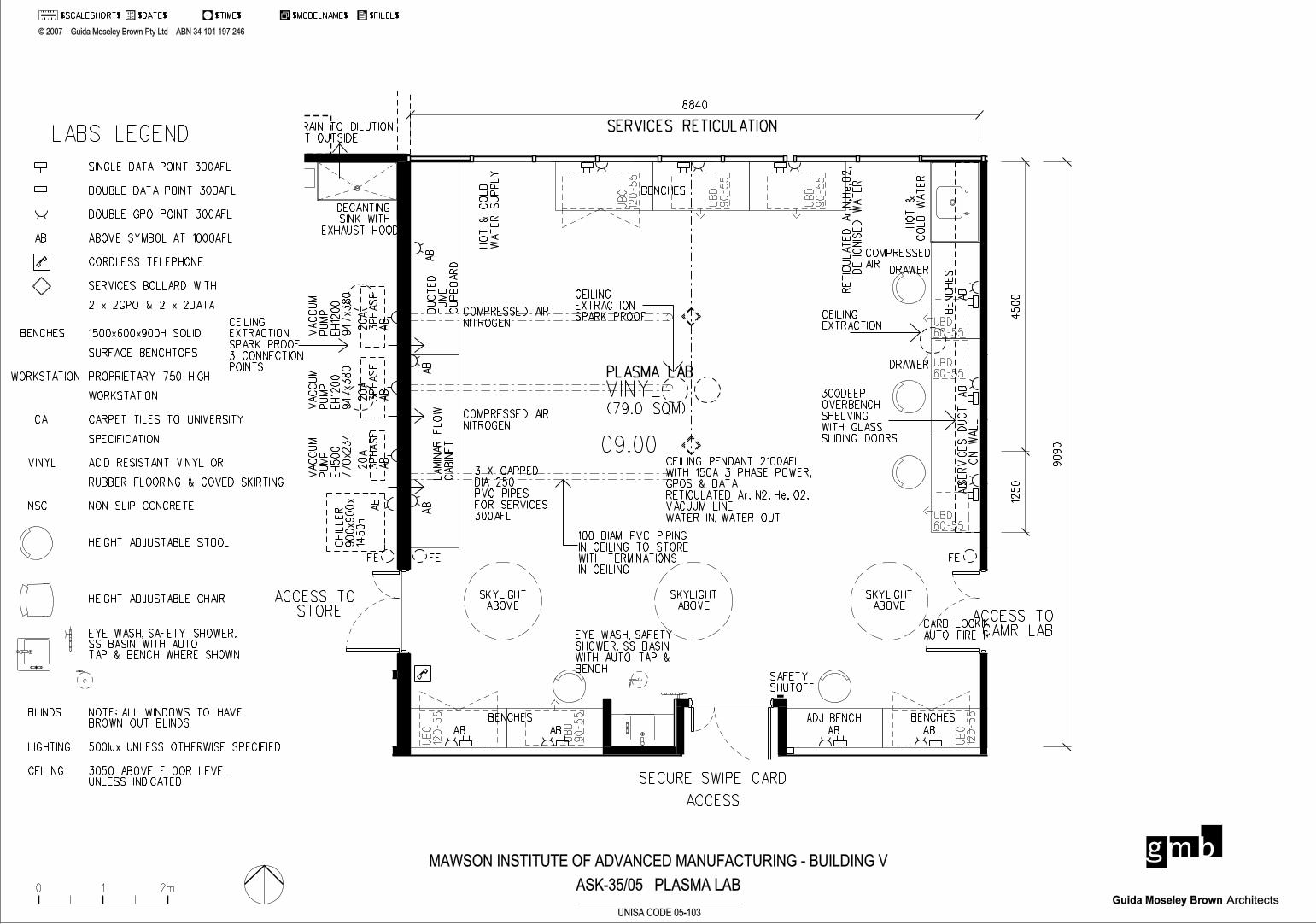
PLASMA LAB
SECURE SWIPE CARD
ACCESS
SERVICES RETICULATION
(79.0 SQM)
8840
9090
ACCESS TO CAMR LAB
ACCESS TO STORE
12
50
45
00
ASK-35/05 PLASMA LAB0 1 2m
' 2007 Guida Moseley Brown Pty Ltd ABN 34 101 197 246
ArchitectsGuida Moseley Brown
$DATE$ $TIME$ $MODELNAME$ $FILEL$$SCALESHORT$1 2
UNISA CODE 05-103
MAWSON INSTITUTE OF ADVANCED MANUFACTURING - BUILDING V
SINGLE DATA POINT 300AFL
DOUBLE DATA POINT 300AFL
DOUBLE GPO POINT 300AFL
ABOVE SYMBOL AT 1000AFLAB
CORDLESS TELEPHONE
BENCHES 1500x600x900H SOLID
SURFACE BENCHTOPS
WORKSTATION PROPRIETARY 750 HIGH
WORKSTATION
SERVICES BOLLARD WITH
2 x 2GPO & 2 x 2DATA
CA CARPET TILES TO UNIVERSITY
SPECIFICATION
VINYL
LABS LEGEND
HEIGHT ADJUSTABLE STOOL
HEIGHT ADJUSTABLE CHAIR
EYE WASH, SAFETY SHOWER.SS BASIN WITH AUTO TAP & BENCH WHERE SHOWN
NOTE: ALL WINDOWS TO HAVEBROWN OUT BLINDS
NSC NON SLIP CONCRETE
LIGHTING 500lux UNLESS OTHERWISE SPECIFIED
BLINDS
ACID RESISTANT VINYL OR
RUBBER FLOORING & COVED SKIRTING
CEILING 3050 ABOVE FLOOR LEVELUNLESS INDICATED
VINYLA
B
AB
AB
AB
ABAB AB AB
AB
AB
AB
LA
MIN
AR
FL
OW
CA
BIN
ET
BENCHES
CEILING
EXTRACTION
SPARK PROOF
HO
T
&
CO
LD
WA
TE
R
SU
PP
LY
DU
CT
ED
FU
ME
CU
PB
OA
RD
300DEEP
OVERBENCH
SHELVING
WITH GLASS
SLIDING DOORS
CEILING
EXTRACTION
BENCHES
BE
NC
HE
S
ADJ BENCH BENCHES
SE
RVIC
ES
DU
CT
ON
WA
LL
CHIL
LE
R
900x900x
14
50h
20
A
3P
HA
SE
AB
20
A
3P
HA
SE
AB
20
A
3P
HA
SE
AB
VA
CC
UM
PU
MP
EH
500
77
0x23
4
VA
CC
UM
PU
MP
EH
1200
94
7x3
80
VA
CC
UM
PU
MP
EH
12
00
94
7x3
80
SKYLIGHT
ABOVE
SKYLIGHT
ABOVE
SKYLIGHT
ABOVE
DRAWER
DRAWER
FE FEFE
SAFETYSHUTOFF
EYE WASH, SAFETY
SHOWER. SS BASIN
WITH AUTO TAP &
BENCH
3 X CAPPED
DIA 250
PVC PIPES
FOR SERVICES
300AFL
CEILING
EXTRACTION
SPARK PROOF
3 CONNECTION
POINTS
RE
TIC
UL
AT
ED
Ar,N,H
e,O
2,
DE-IO
NIS
ED
WA
TE
R
HO
T
&
CO
LD
WA
TE
R
COMPRESSED AIR
NITROGEN
COMPRESSED AIR
NITROGEN
CARD LOCKING WITH
AUTO FIRE RELEASE
CEILING PENDANT 2100AFL
WITH 150A 3 PHASE POWER,
GPOS & DATA
RETICULATED Ar, N2, He, O2,
VACUUM LINE
WATER IN, WATER OUT
COMPRESSED
AIR
UB
C
12
0-5
5
UB
C
12
0-5
5
UB
C
12
0-5
5
UBD60-55
UBD60-55
UBD60-55
UB
D
90-5
5
UB
D
90-5
5
UB
D
90-5
5
100 DIAM PVC PIPING
IN CEILING TO STORE
WITH TERMINATIONS
IN CEILING
DECANTING
SINK WITH
EXHAUST HOOD
DRAIN TO DILUTION
PIT OUTSIDE
09.00
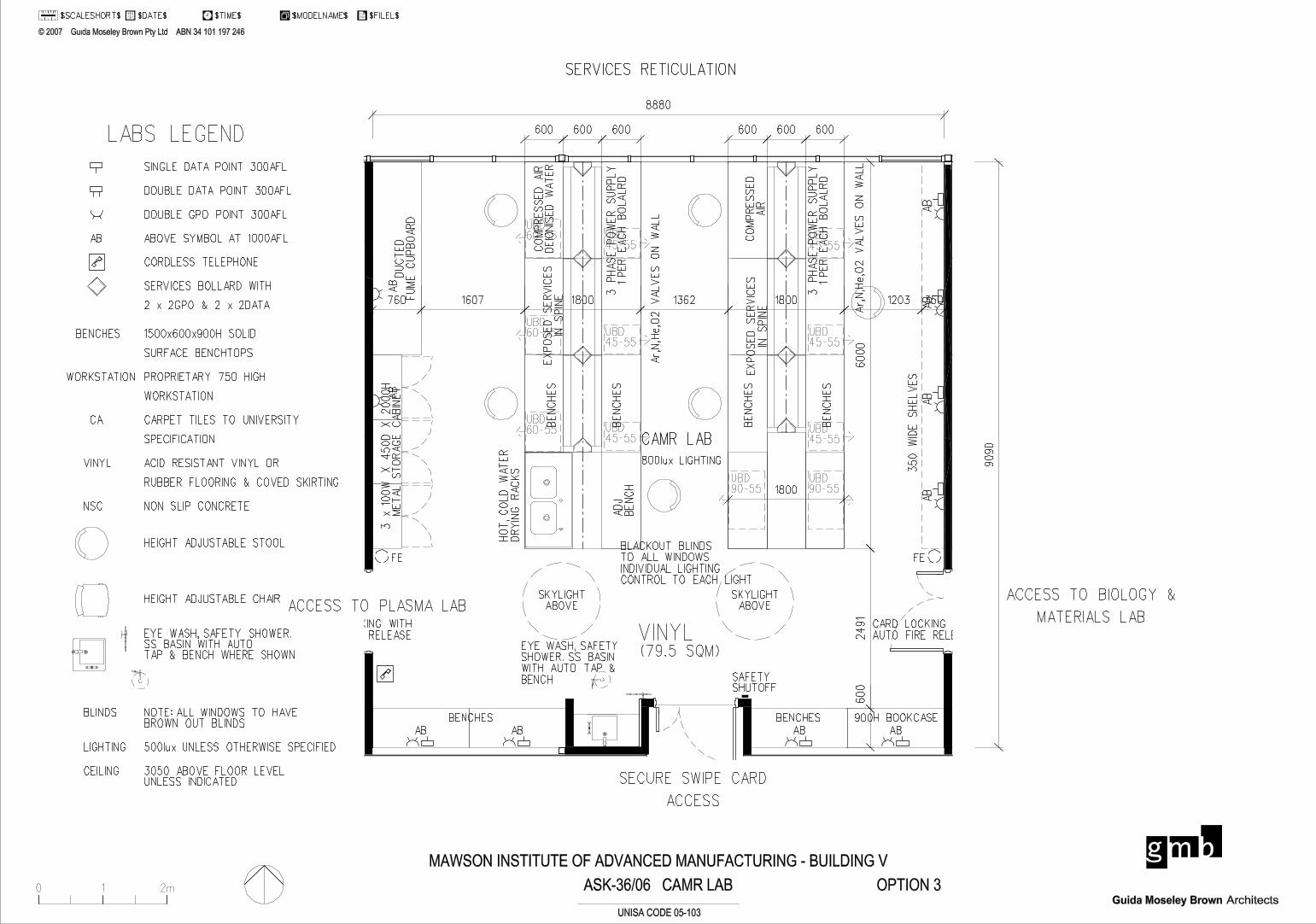
ACCESS TO PLASMA LAB
SECURE SWIPE CARD
ACCESS
SERVICES RETICULATION
ASK-36/06 CAMR LAB
CAMR LAB
(79.5 SQM)
ACCESS TO BIOLOGY &
MATERIALS LAB
8880
90
90
6000
2491
60
0
800lux LIGHTING
BLACKOUT BLINDS
TO ALL WINDOWS
INDIVIDUAL LIGHTING
CONTROL TO EACH LIGHT
1800
OPTION 3
600 600 600 600 600 600
0 1 2m
' 2007 Guida Moseley Brown Pty Ltd ABN 34 101 197 246
ArchitectsGuida Moseley Brown
$DATE$ $TIME$ $MODELNAME$ $FILEL$$SCALESHORT$1 2
UNISA CODE 05-103
MAWSON INSTITUTE OF ADVANCED MANUFACTURING - BUILDING V
VINYL
AB
AB
AB
AB
AB
AB
AB
ABABAB
BENCHES BENCHES
ON
WA
LL
DU
CT
ED
FU
ME
CU
PB
OA
RD
2100 H
IGH
SKYLIGHT
ABOVE
SKYLIGHT
ABOVE
FEFE
SAFETYSHUTOFF
EYE WASH, SAFETY
SHOWER. SS BASIN
WITH AUTO TAP &
BENCH
3 x
100W
X 4
50D
X 2
000H
M
ET
AL
ST
OR
AG
E C
AB
INE
T
350 W
IDE
SH
EL
VE
S
CARD LOCKING WITH
AUTO FIRE RELEASE
CARD LOCKING WITH
AUTO FIRE RELEASE
900H BOOKCASE
760 1607 1800 1362 1800 1203 350
BE
NC
HE
S
UBD45-55
UBD60-55
BE
NC
HE
S
HO
T,
CO
LD
WA
TE
R
DR
YIN
G R
AC
KS
UBD45-55
EX
PO
SE
D S
ER
VIC
ES
IN S
PIN
E
UBD60-55
UBD60-55
3 P
HA
SE
PO
WE
R S
UP
PL
Y1 P
ER
EA
CH
BO
LA
LR
D
UBD45-55
Ar,
N,H
e,O
2 V
AL
VE
S O
N W
AL
L
CO
MP
RE
SS
ED
AIR
DE
ION
ISE
D W
AT
ER
AD
J
BE
NC
H
UBD90-55
UBD45-55
BE
NC
HE
S
BE
NC
HE
SE
XP
OS
ED
SE
RV
ICE
S
IN S
PIN
E
CO
MP
RE
SS
ED
AIR
3 P
HA
SE
PO
WE
R S
UP
PL
Y1 P
ER
EA
CH
BO
LA
LR
D
UBD45-55
Ar,
N,H
e,O
2 V
AL
VE
S O
N W
AL
L
UBD45-55
UBD90-55
SINGLE DATA POINT 300AFL
DOUBLE DATA POINT 300AFL
DOUBLE GPO POINT 300AFL
ABOVE SYMBOL AT 1000AFLAB
CORDLESS TELEPHONE
BENCHES 1500x600x900H SOLID
SURFACE BENCHTOPS
WORKSTATION PROPRIETARY 750 HIGH
WORKSTATION
SERVICES BOLLARD WITH
2 x 2GPO & 2 x 2DATA
CA CARPET TILES TO UNIVERSITY
SPECIFICATION
VINYL
LABS LEGEND
HEIGHT ADJUSTABLE STOOL
HEIGHT ADJUSTABLE CHAIR
EYE WASH, SAFETY SHOWER.SS BASIN WITH AUTO TAP & BENCH WHERE SHOWN
NOTE: ALL WINDOWS TO HAVEBROWN OUT BLINDS
NSC NON SLIP CONCRETE
LIGHTING 500lux UNLESS OTHERWISE SPECIFIED
BLINDS
ACID RESISTANT VINYL OR
RUBBER FLOORING & COVED SKIRTING
CEILING 3050 ABOVE FLOOR LEVELUNLESS INDICATED
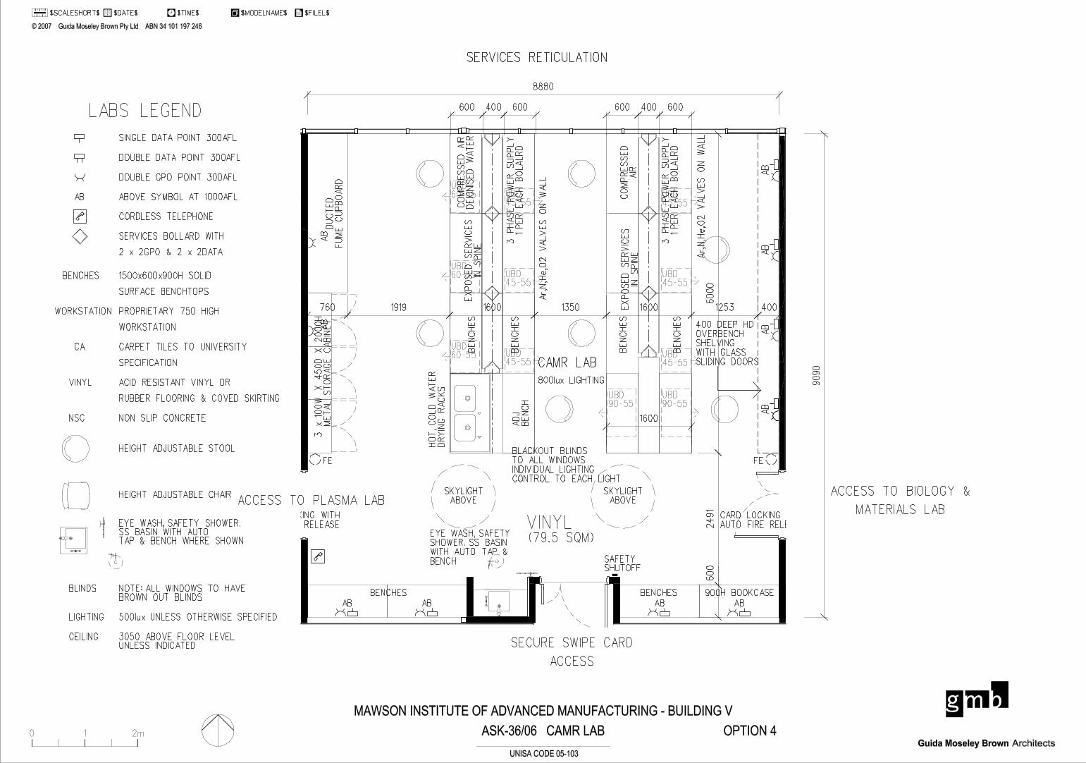
ACCESS TO PLASMA LAB
SECURE SWIPE CARD
ACCESS
SERVICES RETICULATION
ASK-36/06 CAMR LAB
CAMR LAB
(79.5 SQM)
ACCESS TO BIOLOGY &
MATERIALS LAB
8880
90
90
6000
2491
60
0
800lux LIGHTING
BLACKOUT BLINDS
TO ALL WINDOWS
INDIVIDUAL LIGHTING
CONTROL TO EACH LIGHT
1600
OPTION 4
600 400 600 600 400 600
0 1 2m
' 2007 Guida Moseley Brown Pty Ltd ABN 34 101 197 246
ArchitectsGuida Moseley Brown
$DATE$ $TIME$ $MODELNAME$ $FILEL$$SCALESHORT$1 2
UNISA CODE 05-103
MAWSON INSTITUTE OF ADVANCED MANUFACTURING - BUILDING V
VINYL
AB
AB
AB
AB
AB
AB
AB
ABABAB
BENCHES BENCHES
ON
WA
LL
DU
CT
ED
FU
ME
CU
PB
OA
RD
SKYLIGHT
ABOVE
SKYLIGHT
ABOVE
FEFE
SAFETYSHUTOFF
EYE WASH, SAFETY
SHOWER. SS BASIN
WITH AUTO TAP &
BENCH
3 x
100W
X 4
50D
X 2
000H
M
ET
AL
ST
OR
AG
E C
AB
INE
T
CARD LOCKING WITH
AUTO FIRE RELEASE
CARD LOCKING WITH
AUTO FIRE RELEASE
900H BOOKCASE
BE
NC
HE
S
UBD45-55
UBD60-55
BE
NC
HE
S
HO
T,
CO
LD
WA
TE
R
DR
YIN
G R
AC
KS
UBD45-55
EX
PO
SE
D S
ER
VIC
ES
IN S
PIN
E
UBD60-55
UBD60-55
3 P
HA
SE
PO
WE
R S
UP
PL
Y1 P
ER
EA
CH
BO
LA
LR
D
UBD45-55
Ar,
N,H
e,O
2 V
AL
VE
S O
N W
AL
L
CO
MP
RE
SS
ED
AIR
DE
ION
ISE
D W
AT
ER
UBD90-55
UBD45-55
BE
NC
HE
S
BE
NC
HE
SE
XP
OS
ED
SE
RV
ICE
S
IN S
PIN
E
CO
MP
RE
SS
ED
AIR
3 P
HA
SE
PO
WE
R S
UP
PL
Y1 P
ER
EA
CH
BO
LA
LR
D
UBD45-55
Ar,
N,H
e,O
2 V
AL
VE
S O
N W
AL
L
UBD45-55
UBD90-55
AD
J
BE
NC
H
400 DEEP HD
OVERBENCH
SHELVING
WITH GLASS
SLIDING DOORS
760 1919 1600 1350 1600 1253 400
SINGLE DATA POINT 300AFL
DOUBLE DATA POINT 300AFL
DOUBLE GPO POINT 300AFL
ABOVE SYMBOL AT 1000AFLAB
CORDLESS TELEPHONE
BENCHES 1500x600x900H SOLID
SURFACE BENCHTOPS
WORKSTATION PROPRIETARY 750 HIGH
WORKSTATION
SERVICES BOLLARD WITH
2 x 2GPO & 2 x 2DATA
CA CARPET TILES TO UNIVERSITY
SPECIFICATION
VINYL
LABS LEGEND
HEIGHT ADJUSTABLE STOOL
HEIGHT ADJUSTABLE CHAIR
EYE WASH, SAFETY SHOWER.SS BASIN WITH AUTO TAP & BENCH WHERE SHOWN
NOTE: ALL WINDOWS TO HAVEBROWN OUT BLINDS
NSC NON SLIP CONCRETE
LIGHTING 500lux UNLESS OTHERWISE SPECIFIED
BLINDS
ACID RESISTANT VINYL OR
RUBBER FLOORING & COVED SKIRTING
CEILING 3050 ABOVE FLOOR LEVELUNLESS INDICATED

ACCESS TO PLASMA LAB
SECURE SWIPE CARD
ACCESS
SERVICES RETICULATION
ASK-36/06 CAMR LAB
CAMR LAB
(79.5 SQM)
ACCESS TO BIOLOGY &
MATERIALS LAB
8880
90
90
6000
2491
60
0
800lux LIGHTING
BLACKOUT BLINDS
TO ALL WINDOWS
INDIVIDUAL LIGHTING
CONTROL TO EACH LIGHT
1500
OPTION 5
600 300 600 600 300 600
0 1 2m
' 2007 Guida Moseley Brown Pty Ltd ABN 34 101 197 246
ArchitectsGuida Moseley Brown
$DATE$ $TIME$ $MODELNAME$ $FILEL$$SCALESHORT$1 2
UNISA CODE 05-103
MAWSON INSTITUTE OF ADVANCED MANUFACTURING - BUILDING V
VINYL
AB
AB
AB
AB
AB
AB
AB
ABABAB
BENCHES BENCHES
ON
WA
LL
DU
CT
ED
FU
ME
CU
PB
OA
RD
SKYLIGHT
ABOVE
SKYLIGHT
ABOVE
FEFE
SAFETYSHUTOFF
EYE WASH, SAFETY
SHOWER. SS BASIN
WITH AUTO TAP &
BENCH
3 x
100W
X 4
50D
X 2
000H
M
ET
AL
ST
OR
AG
E C
AB
INE
T
CARD LOCKING WITH
AUTO FIRE RELEASE
CARD LOCKING WITH
AUTO FIRE RELEASE
900H BOOKCASE
BE
NC
HE
S
UBD45-55
UBD60-55
BE
NC
HE
S
HO
T,
CO
LD
WA
TE
R
DR
YIN
G R
AC
KS
UBD45-55
EX
PO
SE
D S
ER
VIC
ES
IN S
PIN
E
UBD60-55
UBD60-55
3 P
HA
SE
PO
WE
R S
UP
PL
Y1 P
ER
EA
CH
BO
LA
LR
D
UBD45-55
Ar,
N,H
e,O
2 V
AL
VE
S O
N W
AL
L
CO
MP
RE
SS
ED
AIR
DE
ION
ISE
D W
AT
ER
UBD90-55
UBD45-55
BE
NC
HE
S
BE
NC
HE
SE
XP
OS
ED
SE
RV
ICE
S
IN S
PIN
E
CO
MP
RE
SS
ED
AIR
3 P
HA
SE
PO
WE
R S
UP
PL
Y1 P
ER
EA
CH
BO
LA
LR
D
UBD45-55
Ar,
N,H
e,O
2 V
AL
VE
S O
N W
AL
L
UBD45-55
UBD90-55
AD
J
BE
NC
H
760 1507 1500 1425 1500 1441 750
UBD60-55
UBD60-55
UBD60-55
400 DEEP HD
OVERBENCH
SHELVING
WITH GLASS
SLIDING DOORS
SINGLE DATA POINT 300AFL
DOUBLE DATA POINT 300AFL
DOUBLE GPO POINT 300AFL
ABOVE SYMBOL AT 1000AFLAB
CORDLESS TELEPHONE
BENCHES 1500x600x900H SOLID
SURFACE BENCHTOPS
WORKSTATION PROPRIETARY 750 HIGH
WORKSTATION
SERVICES BOLLARD WITH
2 x 2GPO & 2 x 2DATA
CA CARPET TILES TO UNIVERSITY
SPECIFICATION
VINYL
LABS LEGEND
HEIGHT ADJUSTABLE STOOL
HEIGHT ADJUSTABLE CHAIR
EYE WASH, SAFETY SHOWER.SS BASIN WITH AUTO TAP & BENCH WHERE SHOWN
NOTE: ALL WINDOWS TO HAVEBROWN OUT BLINDS
NSC NON SLIP CONCRETE
LIGHTING 500lux UNLESS OTHERWISE SPECIFIED
BLINDS
ACID RESISTANT VINYL OR
RUBBER FLOORING & COVED SKIRTING
CEILING 3050 ABOVE FLOOR LEVELUNLESS INDICATED

ACCESS TO PLASMA LAB
SECURE SWIPE CARD
ACCESS
SERVICES RETICULATION
ASK-36/06 CAMR LAB
CAMR LAB
(79.5 SQM)
ACCESS TO BIOLOGY &
MATERIALS LAB
8880
90
90
6000
2491
60
0
800lux LIGHTING
BLACKOUT BLINDS
TO ALL WINDOWS
INDIVIDUAL LIGHTING
CONTROL TO EACH LIGHT
1800
OPTION 3
600 600 600 600 600 600
0 1 2m
' 2007 Guida Moseley Brown Pty Ltd ABN 34 101 197 246
ArchitectsGuida Moseley Brown
$DATE$ $TIME$ $MODELNAME$ $FILEL$$SCALESHORT$1 2
UNISA CODE 05-103
MAWSON INSTITUTE OF ADVANCED MANUFACTURING - BUILDING V
VINYL
AB
AB
AB
AB
AB
AB
AB
ABABAB
BENCHES BENCHES
ON
WA
LL
DU
CT
ED
FU
ME
CU
PB
OA
RD
2100 H
IGH
SKYLIGHT
ABOVE
SKYLIGHT
ABOVE
FEFE
SAFETYSHUTOFF
EYE WASH, SAFETY
SHOWER. SS BASIN
WITH AUTO TAP &
BENCH
3 x
100W
X 4
50D
X 2
000H
M
ET
AL
ST
OR
AG
E C
AB
INE
T
350 W
IDE
SH
EL
VE
S
CARD LOCKING WITH
AUTO FIRE RELEASE
CARD LOCKING WITH
AUTO FIRE RELEASE
900H BOOKCASE
760 1607 1800 1362 1800 1203 350
BE
NC
HE
S
UBD45-55
UBD60-55
BE
NC
HE
S
HO
T,
CO
LD
WA
TE
R
DR
YIN
G R
AC
KS
UBD45-55
EX
PO
SE
D S
ER
VIC
ES
IN S
PIN
E
UBD60-55
UBD60-55
3 P
HA
SE
PO
WE
R S
UP
PL
Y1 P
ER
EA
CH
BO
LA
LR
D
UBD45-55
Ar,
N,H
e,O
2 V
AL
VE
S O
N W
AL
L
CO
MP
RE
SS
ED
AIR
DE
ION
ISE
D W
AT
ER
AD
J
BE
NC
H
UBD90-55
UBD45-55
BE
NC
HE
S
BE
NC
HE
SE
XP
OS
ED
SE
RV
ICE
S
IN S
PIN
E
CO
MP
RE
SS
ED
AIR
3 P
HA
SE
PO
WE
R S
UP
PL
Y1 P
ER
EA
CH
BO
LA
LR
D
UBD45-55
Ar,
N,H
e,O
2 V
AL
VE
S O
N W
AL
L
UBD45-55
UBD90-55
SINGLE DATA POINT 300AFL
DOUBLE DATA POINT 300AFL
DOUBLE GPO POINT 300AFL
ABOVE SYMBOL AT 1000AFLAB
CORDLESS TELEPHONE
BENCHES 1500x600x900H SOLID
SURFACE BENCHTOPS
WORKSTATION PROPRIETARY 750 HIGH
WORKSTATION
SERVICES BOLLARD WITH
2 x 2GPO & 2 x 2DATA
CA CARPET TILES TO UNIVERSITY
SPECIFICATION
VINYL
LABS LEGEND
HEIGHT ADJUSTABLE STOOL
HEIGHT ADJUSTABLE CHAIR
EYE WASH, SAFETY SHOWER.SS BASIN WITH AUTO TAP & BENCH WHERE SHOWN
NOTE: ALL WINDOWS TO HAVEBROWN OUT BLINDS
NSC NON SLIP CONCRETE
LIGHTING 500lux UNLESS OTHERWISE SPECIFIED
BLINDS
ACID RESISTANT VINYL OR
RUBBER FLOORING & COVED SKIRTING
CEILING 3050 ABOVE FLOOR LEVELUNLESS INDICATED

ACCESS TO PLASMA LAB
SECURE SWIPE CARD
ACCESS
SERVICES RETICULATION
ASK-36/06 CAMR LAB
CAMR LAB
(79.5 SQM)
ACCESS TO BIOLOGY &
MATERIALS LAB
8880
90
90
6000
2491
60
0
800lux LIGHTING
BLACKOUT BLINDS
TO ALL WINDOWS
INDIVIDUAL LIGHTING
CONTROL TO EACH LIGHT
1600
OPTION 4
600 400 600 600 400 600
0 1 2m
' 2007 Guida Moseley Brown Pty Ltd ABN 34 101 197 246
ArchitectsGuida Moseley Brown
$DATE$ $TIME$ $MODELNAME$ $FILEL$$SCALESHORT$1 2
UNISA CODE 05-103
MAWSON INSTITUTE OF ADVANCED MANUFACTURING - BUILDING V
VINYL
AB
AB
AB
AB
AB
AB
AB
ABABAB
BENCHES BENCHES
ON
WA
LL
DU
CT
ED
FU
ME
CU
PB
OA
RD
SKYLIGHT
ABOVE
SKYLIGHT
ABOVE
FEFE
SAFETYSHUTOFF
EYE WASH, SAFETY
SHOWER. SS BASIN
WITH AUTO TAP &
BENCH
3 x
100W
X 4
50D
X 2
000H
M
ET
AL
ST
OR
AG
E C
AB
INE
T
CARD LOCKING WITH
AUTO FIRE RELEASE
CARD LOCKING WITH
AUTO FIRE RELEASE
900H BOOKCASE
BE
NC
HE
S
UBD45-55
UBD60-55
BE
NC
HE
S
HO
T,
CO
LD
WA
TE
R
DR
YIN
G R
AC
KS
UBD45-55
EX
PO
SE
D S
ER
VIC
ES
IN S
PIN
E
UBD60-55
UBD60-55
3 P
HA
SE
PO
WE
R S
UP
PL
Y1 P
ER
EA
CH
BO
LA
LR
D
UBD45-55
Ar,
N,H
e,O
2 V
AL
VE
S O
N W
AL
L
CO
MP
RE
SS
ED
AIR
DE
ION
ISE
D W
AT
ER
UBD90-55
UBD45-55
BE
NC
HE
S
BE
NC
HE
SE
XP
OS
ED
SE
RV
ICE
S
IN S
PIN
E
CO
MP
RE
SS
ED
AIR
3 P
HA
SE
PO
WE
R S
UP
PL
Y1 P
ER
EA
CH
BO
LA
LR
D
UBD45-55
Ar,
N,H
e,O
2 V
AL
VE
S O
N W
AL
L
UBD45-55
UBD90-55
AD
J
BE
NC
H
400 DEEP HD
OVERBENCH
SHELVING
WITH GLASS
SLIDING DOORS
760 1919 1600 1350 1600 1253 400
SINGLE DATA POINT 300AFL
DOUBLE DATA POINT 300AFL
DOUBLE GPO POINT 300AFL
ABOVE SYMBOL AT 1000AFLAB
CORDLESS TELEPHONE
BENCHES 1500x600x900H SOLID
SURFACE BENCHTOPS
WORKSTATION PROPRIETARY 750 HIGH
WORKSTATION
SERVICES BOLLARD WITH
2 x 2GPO & 2 x 2DATA
CA CARPET TILES TO UNIVERSITY
SPECIFICATION
VINYL
LABS LEGEND
HEIGHT ADJUSTABLE STOOL
HEIGHT ADJUSTABLE CHAIR
EYE WASH, SAFETY SHOWER.SS BASIN WITH AUTO TAP & BENCH WHERE SHOWN
NOTE: ALL WINDOWS TO HAVEBROWN OUT BLINDS
NSC NON SLIP CONCRETE
LIGHTING 500lux UNLESS OTHERWISE SPECIFIED
BLINDS
ACID RESISTANT VINYL OR
RUBBER FLOORING & COVED SKIRTING
CEILING 3050 ABOVE FLOOR LEVELUNLESS INDICATED
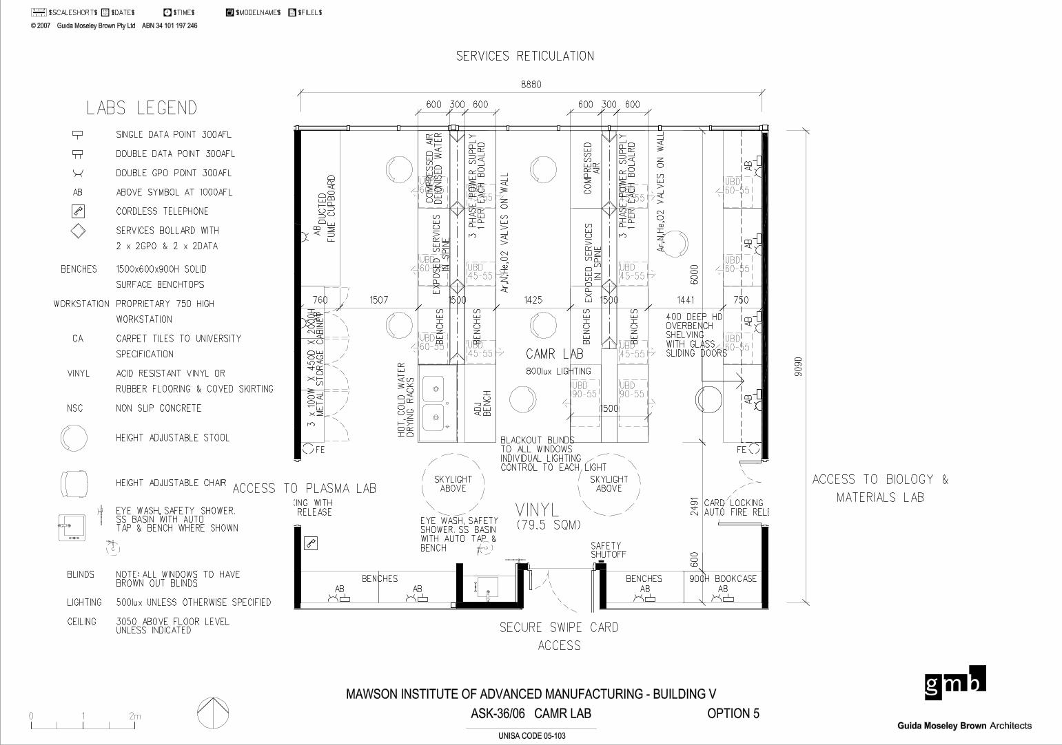
ACCESS TO PLASMA LAB
SECURE SWIPE CARD
ACCESS
SERVICES RETICULATION
ASK-36/06 CAMR LAB
CAMR LAB
(79.5 SQM)
ACCESS TO BIOLOGY &
MATERIALS LAB
8880
90
90
6000
2491
60
0
800lux LIGHTING
BLACKOUT BLINDS
TO ALL WINDOWS
INDIVIDUAL LIGHTING
CONTROL TO EACH LIGHT
1500
OPTION 5
600 300 600 600 300 600
0 1 2m
' 2007 Guida Moseley Brown Pty Ltd ABN 34 101 197 246
ArchitectsGuida Moseley Brown
$DATE$ $TIME$ $MODELNAME$ $FILEL$$SCALESHORT$1 2
UNISA CODE 05-103
MAWSON INSTITUTE OF ADVANCED MANUFACTURING - BUILDING V
VINYL
AB
AB
AB
AB
AB
AB
AB
ABABAB
BENCHES BENCHES
ON
WA
LL
DU
CT
ED
FU
ME
CU
PB
OA
RD
SKYLIGHT
ABOVE
SKYLIGHT
ABOVE
FEFE
SAFETYSHUTOFF
EYE WASH, SAFETY
SHOWER. SS BASIN
WITH AUTO TAP &
BENCH
3 x
100W
X 4
50D
X 2
000H
M
ET
AL
ST
OR
AG
E C
AB
INE
T
CARD LOCKING WITH
AUTO FIRE RELEASE
CARD LOCKING WITH
AUTO FIRE RELEASE
900H BOOKCASE
BE
NC
HE
S
UBD45-55
UBD60-55
BE
NC
HE
S
HO
T,
CO
LD
WA
TE
R
DR
YIN
G R
AC
KS
UBD45-55
EX
PO
SE
D S
ER
VIC
ES
IN S
PIN
E
UBD60-55
UBD60-55
3 P
HA
SE
PO
WE
R S
UP
PL
Y1 P
ER
EA
CH
BO
LA
LR
D
UBD45-55
Ar,
N,H
e,O
2 V
AL
VE
S O
N W
AL
L
CO
MP
RE
SS
ED
AIR
DE
ION
ISE
D W
AT
ER
UBD90-55
UBD45-55
BE
NC
HE
S
BE
NC
HE
SE
XP
OS
ED
SE
RV
ICE
S
IN S
PIN
E
CO
MP
RE
SS
ED
AIR
3 P
HA
SE
PO
WE
R S
UP
PL
Y1 P
ER
EA
CH
BO
LA
LR
D
UBD45-55
Ar,
N,H
e,O
2 V
AL
VE
S O
N W
AL
L
UBD45-55
UBD90-55
AD
J
BE
NC
H
760 1507 1500 1425 1500 1441 750
UBD60-55
UBD60-55
UBD60-55
400 DEEP HD
OVERBENCH
SHELVING
WITH GLASS
SLIDING DOORS
SINGLE DATA POINT 300AFL
DOUBLE DATA POINT 300AFL
DOUBLE GPO POINT 300AFL
ABOVE SYMBOL AT 1000AFLAB
CORDLESS TELEPHONE
BENCHES 1500x600x900H SOLID
SURFACE BENCHTOPS
WORKSTATION PROPRIETARY 750 HIGH
WORKSTATION
SERVICES BOLLARD WITH
2 x 2GPO & 2 x 2DATA
CA CARPET TILES TO UNIVERSITY
SPECIFICATION
VINYL
LABS LEGEND
HEIGHT ADJUSTABLE STOOL
HEIGHT ADJUSTABLE CHAIR
EYE WASH, SAFETY SHOWER.SS BASIN WITH AUTO TAP & BENCH WHERE SHOWN
NOTE: ALL WINDOWS TO HAVEBROWN OUT BLINDS
NSC NON SLIP CONCRETE
LIGHTING 500lux UNLESS OTHERWISE SPECIFIED
BLINDS
ACID RESISTANT VINYL OR
RUBBER FLOORING & COVED SKIRTING
CEILING 3050 ABOVE FLOOR LEVELUNLESS INDICATED
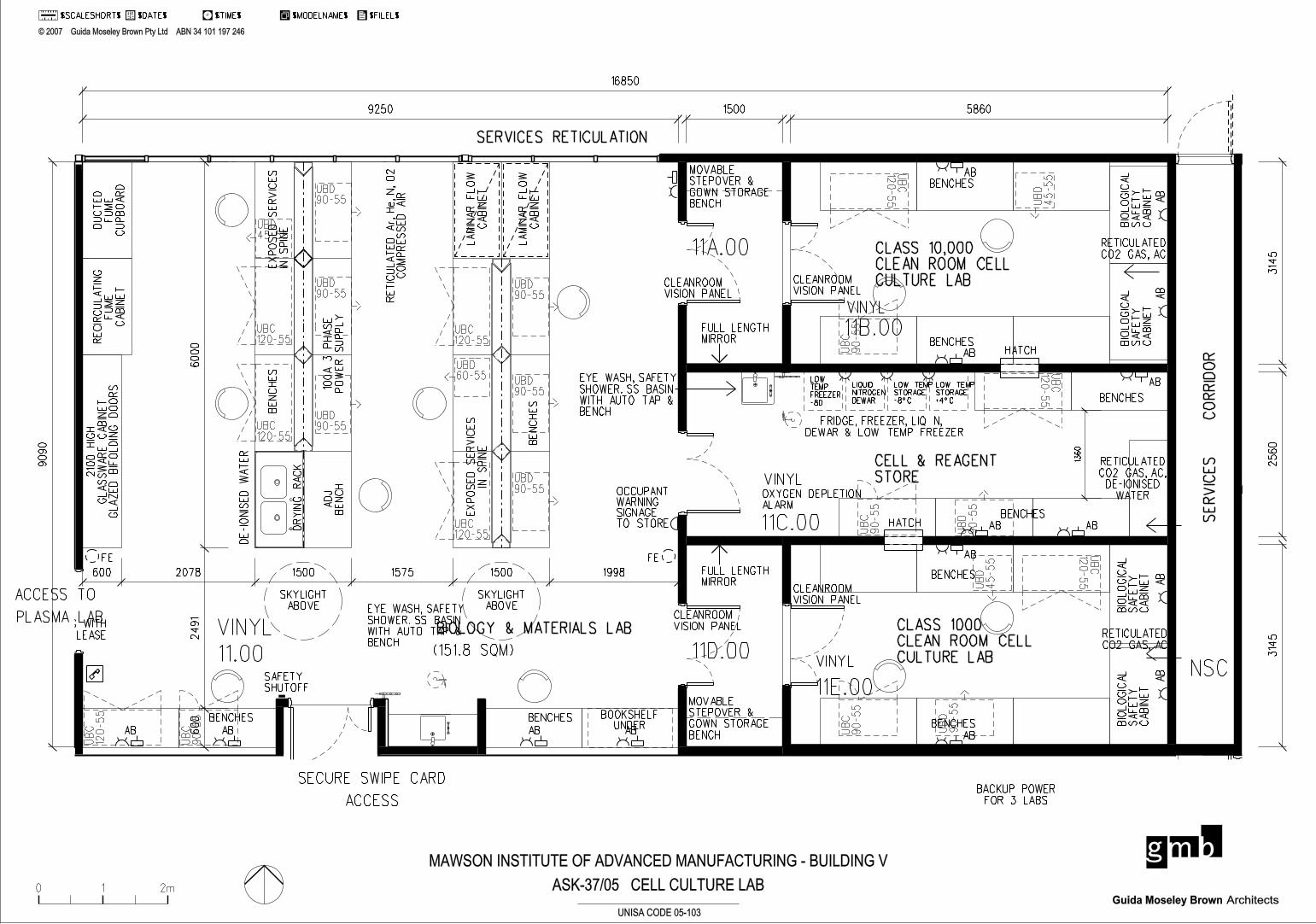
SECURE SWIPE CARD
ACCESS
SERVICES RETICULATION
ACCESS TO
PLASMA LAB
CELL & REAGENT
STORE
SE
RVIC
ES
CO
RRID
OR
BIOLOGY & MATERIALS LAB
BACKUP POWER
FOR 3 LABS
(151.8 SQM)
9090
9250
16850
5860
600
24
91
6000
19981500157515002078600
314
53
14
52
560
1500
CLASS 10,000
CLEAN ROOM CELL
CULTURE LAB
CLASS 1000
CLEAN ROOM CELL
CULTURE LAB
ASK-37/05 CELL CULTURE LAB0 1 2m
' 2007 Guida Moseley Brown Pty Ltd ABN 34 101 197 246
ArchitectsGuida Moseley Brown
$DATE$ $TIME$ $MODELNAME$ $FILEL$$SCALESHORT$1 2
UNISA CODE 05-103
MAWSON INSTITUTE OF ADVANCED MANUFACTURING - BUILDING V
VINYL
VINYL
VINYL
NSC
AB AB AB ABAB
AB
AB
AB
AB AB
AB
AB
AB
AB
AB
BENCHES
ADJ
BE
NC
H
100
A 3
PH
AS
E
PO
WE
R
SU
PP
LY
BE
NC
HE
S
RE
CIR
CU
LA
TIN
G
FU
ME
CA
BIN
ET
DU
CT
ED
FU
ME
CU
PB
OA
RD
EX
PO
SE
D
SE
RVIC
ES
IN
SPIN
E
LA
MIN
AR
FL
OW
CA
BIN
ET
LA
MIN
AR
FL
OW
CA
BIN
ET
BE
NC
HE
S
EX
PO
SE
D
SE
RVIC
ES
IN
SPIN
E
BENCHESBENCHES
BENCHES
BIO
LO
GIC
AL
SA
FE
TY
CA
BIN
ET
BIO
LO
GIC
AL
SA
FE
TY
CA
BIN
ET
RETICULATED
CO2 GAS, AC
BENCHES
HATCHBENCHES
BENCHES
BENCHESHATCH
BIO
LO
GIC
AL
SA
FE
TY
CA
BIN
ET
BIO
LO
GIC
AL
SA
FE
TY
CA
BIN
ET
LOW TEMP
STORAGE
+4^C
LOW TEMP
STORAGE
-8^C
LIQUID
NITROGEN
DEWAR
FRIDGE, FREEZER, LIQ N,
DEWAR & LOW TEMP FREEZER
RETICULATED
CO2 GAS, AC
EYE WASH, SAFETY
SHOWER. SS BASIN
WITH AUTO TAP &
BENCH
2100
HIG
H
GL
AS
SW
AR
E
CA
BIN
ET
GL
AZ
ED
BIF
OL
DIN
G
DO
OR
S
SKYLIGHT
ABOVE
SKYLIGHT
ABOVE
VINYL
DR
YIN
G
RA
CK
DE-IO
NIS
ED
WA
TE
R
FEFE
SAFETYSHUTOFF
EYE WASH, SAFETY
SHOWER. SS BASIN
WITH AUTO TAP &
BENCH
CLEANROOM
VISION PANEL
CLEANROOM
VISION PANEL
MOVABLE
STEPOVER &
GOWN STORAGE
BENCH
CLEANROOM
VISION PANELCLEANROOM
VISION PANEL
MOVABLE
STEPOVER &
GOWN STORAGE
BENCH
RE
TIC
UL
AT
ED
Ar,
He,
N,
O2
CO
MP
RE
SS
ED
AIR
OXYGEN DEPLETION
ALARM
RETICULATED
CO2 GAS, AC,
DE-IONISED
WATER
BOOKSHELFUNDER
CARD LOCKING WITH
AUTO FIRE RELEASE
LOW
TEMP
FREEZER
-80
FULL LENGTH
MIRROR
FULL LENGTH
MIRROR
UB
C12
0-55
UB
C12
0-55
UB
C12
0-55
UBC120-55
UBC120-55
UBC120-55
UB
C
120-5
5
UB
C
90-5
5
UB
C
90-5
5U
BC
90-5
5
UB
C
90-5
5
UBC120-55
UBD90-55
UBD90-55
UBD90-55
UBD90-55
UBD90-55
UBD90-55
UB
D
90-5
5
UB
D
90-5
5
UB
D
45-5
5
UB
D
45-5
5
UBD45-55
UBD60-55
OCCUPANT WARNING SIGNAGE TO STORE
13
60
11.00
11B.00
11C.00
11E.00
11D.00
11A.00
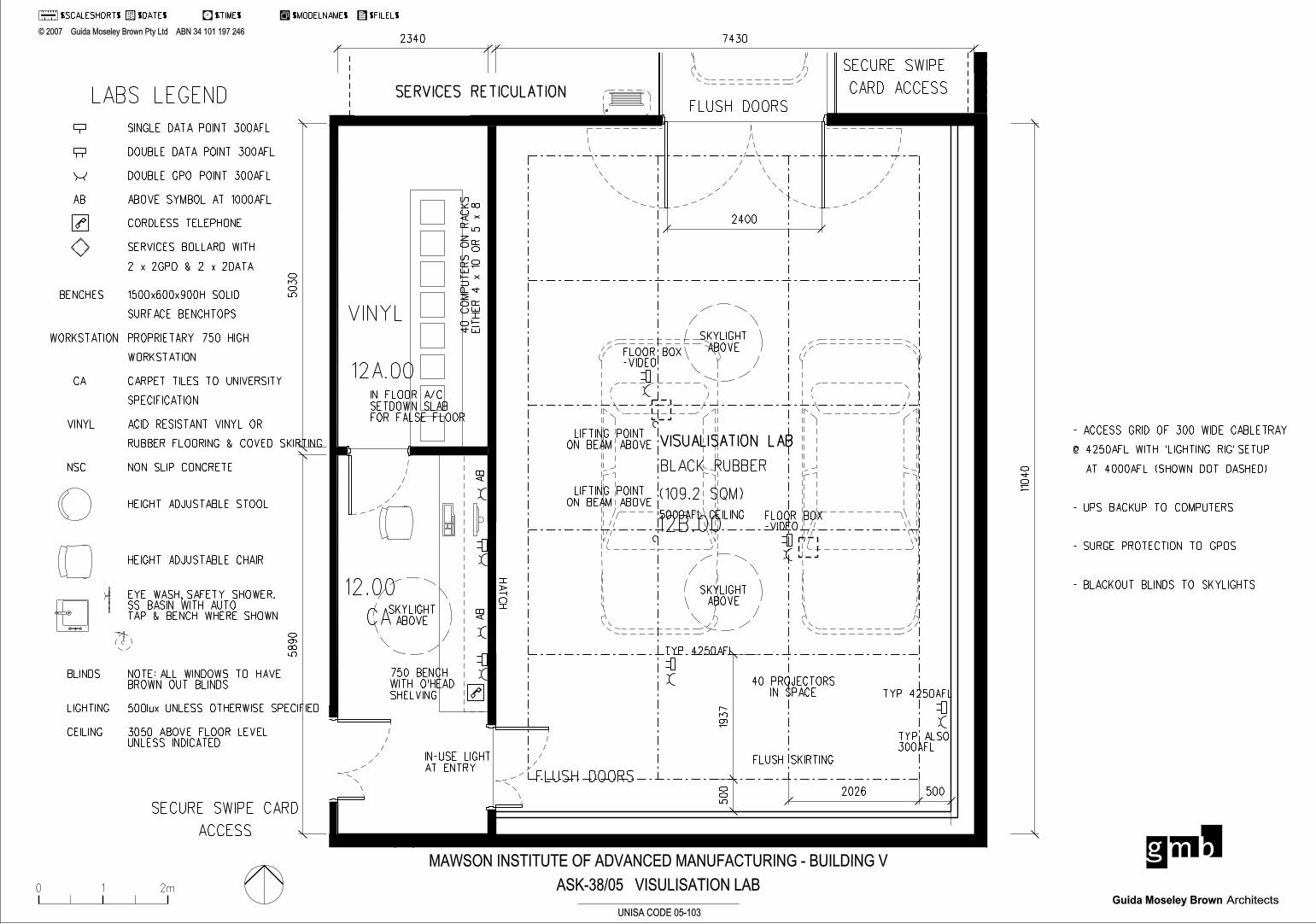
SECURE SWIPE CARD
ACCESS
SERVICES RETICULATION
VISUALISATION LAB
(109.2 SQM)
FLUSH DOORS
1104
0
74302340
58
90
503
0
5000AFL CEILING
2400
ASK-38/05 VISULISATION LAB
2026 500
500
193
7
- ACCESS GRID OF 300 WIDE CABLETRAY
@ 4250AFL WITH ’LIGHTING RIG’ SETUP
AT 4000AFL (SHOWN DOT DASHED)
- UPS BACKUP TO COMPUTERS
- SURGE PROTECTION TO GPOS
- BLACKOUT BLINDS TO SKYLIGHTS
SECURE SWIPE
CARD ACCESS
0 1 2m
' 2007 Guida Moseley Brown Pty Ltd ABN 34 101 197 246
ArchitectsGuida Moseley Brown
$DATE$ $TIME$ $MODELNAME$ $FILEL$$SCALESHORT$1 2
UNISA CODE 05-103
MAWSON INSTITUTE OF ADVANCED MANUFACTURING - BUILDING V
FLUSH DOORS
CA
VINYL
AB
AB
TYP 4250AFL
40 PROJECTORS
IN SPACE
LIFTING POINT
ON BEAM ABOVE
LIFTING POINT
ON BEAM ABOVE
TYP 4250AFL
TYP ALSO300AFL
750 BENCH
WITH O’HEAD
SHELVING
IN FLOOR A/C
SETDOWN SLAB
FOR FALSE FLOOR
SKYLIGHT
ABOVE
SKYLIGHT
ABOVE
SKYLIGHT
ABOVEFLOOR BOX-VIDEO
FLOOR BOX-VIDEO
IN-USE LIGHT
AT ENTRY
40
CO
MP
UT
ER
S
ON
RA
CK
S
EIT
HE
R
4
x 10
OR
5
x 8
HAT
CH
BLACK RUBBER
FLUSH SKIRTING
12B.00
12.00
12A.00
SINGLE DATA POINT 300AFL
DOUBLE DATA POINT 300AFL
DOUBLE GPO POINT 300AFL
ABOVE SYMBOL AT 1000AFLAB
CORDLESS TELEPHONE
BENCHES 1500x600x900H SOLID
SURFACE BENCHTOPS
WORKSTATION PROPRIETARY 750 HIGH
WORKSTATION
SERVICES BOLLARD WITH
2 x 2GPO & 2 x 2DATA
CA CARPET TILES TO UNIVERSITY
SPECIFICATION
VINYL
LABS LEGEND
HEIGHT ADJUSTABLE STOOL
HEIGHT ADJUSTABLE CHAIR
EYE WASH, SAFETY SHOWER.SS BASIN WITH AUTO TAP & BENCH WHERE SHOWN
NOTE: ALL WINDOWS TO HAVEBROWN OUT BLINDS
NSC NON SLIP CONCRETE
LIGHTING 500lux UNLESS OTHERWISE SPECIFIED
BLINDS
ACID RESISTANT VINYL OR
RUBBER FLOORING & COVED SKIRTING
CEILING 3050 ABOVE FLOOR LEVELUNLESS INDICATED

DESIGN DEVELOPMENT REPORT | SEPTEMBER 2007
APPENDIX H: DRAWINGS