Embed Size (px)
Citation preview
UNI/PdR 30:2017
© UNI 1
FOREWORD
The UNI/PdR 30:2017 does not have the status of a UNI technical standard, it is, instead, a
document published by UNI, as provided for in Regulation (EU) No 1025/2012, and adopting the
requirements related to practices shared by the following proposers who have signed an agreement
of collaboration with UNI:
AIPE - Associazione Italiana Polistirene Espanso
Via M.A. Colonna, 46
20149 Milano
This UNI/PdR has been developed by the working group "Formworks made with EPS”, led by UNI
and constituted by the following experts:
Marco Piana – Project Leader (AIPE)
Alessandro Jug (REXPOL Srl)
Domenico Sambataro (PONTAROLO ENGINEERING SpA)
Romeo Tonello (REXPOL Srl)
Alberto Zacchè (POLIESPANSO Srl)
This UNI/PdR has been ratified by UNI President on 8 March 2017.
UNI/PdRs, adopted exclusively on a national level, are part of the “European standardisation delivelirables”, as provided
for in Regulation (EU) No 1025/2012, and they are documents introducing technical requirements that are developed
through a fast track process reflecting the consensus of the participants only, under the operational direction of UNI.
UNI/PdRs are valid for a limited duration of 5 years or until its transformation into another deliverable (UNI, UNI/TS,
UNI/TR) whichever is the sooner. When 5 years have passed, the UNI/PdR shall be withdrawn if it is not transformed into
another deliverable.
Further to the application of this UNI/PdR, anyone interested in providing suggestions for its improvement is requested to
send their own contributions to UNI, Italian Organization for Standardization, which shall take them into account.
UNI/PdR 30:2017
© UNI 2
SOMMARIO
INTRODUCTION .......................................................................................................................................................... 4
1 SCOPE ............................................................................................................................................................. 5
2 NORMATIVE REFERENCES .......................................................................................................................... 5
3 TERMS AND DEFINITIONS ............................................................................................................................ 6
4 PRINCIPLES .................................................................................................................................................... 7
5 REQUIREMENTS ............................................................................................................................................. 7
5.1 EPS REQUIREMENTS ..................................................................................................................................... 7
5.1.1 COMPRESSIVE STRENGTH ...................................................................................................................... 8
5.1.2 FLEXURAL STRENGTH .............................................................................................................................. 8
5.1.3 WATER ABSORPTION ................................................................................................................................ 8
5.1.4 PERMEABILITY TO WATER VAPOUR ...................................................................................................... 8
5.1.5 REACTION TO FIRE .................................................................................................................................... 9
5.1.6 THERMAL CONDUCTIVITY AND THERMAL RESISTANCE .................................................................... 9
5.1.7 DANGEROUS SUBSTANCES .................................................................................................................... 9
5.2 REQUIREMENTS OF EPS FORMWORKS ..................................................................................................... 9
5.2.1 DIMENSIONS AND DIMENSIONAL TOLERANCES .................................................................................. 9
5.2.2 SURFACE APPEARANCE ........................................................................................................................ 13
5.2.3 FIRE RESISTANCE OF THE SLAB SYSTEM .......................................................................................... 13
5.2.4 MECHANICAL STRENGTH ....................................................................................................................... 13
5.2.5 THERMAL RESISTANCE OF THE SLAB ................................................................................................. 14
5.2.6 ACOUSTIC PROPERTIES ......................................................................................................................... 14
5.2.7 DURABILITY .............................................................................................................................................. 14
6 TEST METHODS ............................................................................................................................................ 15
6.1 DIMENSIONS OF EPS FORMWORKS ......................................................................................................... 15
6.2 SURFACE APPEARANCE ............................................................................................................................ 15
6.3 COMPRESSIVE STRENGTH ........................................................................................................................ 15
6.4 FLEXURAL STRENGTH ................................................................................................................................ 15
6.5 WATER ABSORPTION .................................................................................................................................. 15
6.6 PERMEABILITY TO WATER VAPOUR ........................................................................................................ 15
UNI/PdR 30:2017
© UNI 3
6.7 REACTION TO FIRE ...................................................................................................................................... 16
6.7.1 FIRE REACTION OF EPS AND THE SLAB SYSTEM .............................................................................. 16
6.7.2 FIRE RESISTANCE OF THE SLAB SYSTEM .......................................................................................... 16
6.8 THERMAL PROPERTIES .............................................................................................................................. 17
6.8.1 THERMAL CONDUCTIVITY ...................................................................................................................... 17
6.8.2 THERMAL RESISTANCE OF THE SLAB ................................................................................................. 17
6.9 MECHANICAL RESISTANCE ....................................................................................................................... 17
6.9.1 SELF-SUPPORT ........................................................................................................................................ 17
6.9.2 WALKABILITY ........................................................................................................................................... 20
6.9.3 STRENGTH OF THE TOE/BASE BEAM ................................................................................................... 22
7 VERIFICATION OF CONFORMITY TO DECLARED PERFORMANCE ...................................................... 22
APPENDIX – REACTION TO FIRE OF LIGHTWEIGHT SLAB SYSTEMS .............................................................. 26
UNI/PdR 30:2017
© UNI 4
INTRODUCTION
The document is a guideline for characterizing the constituent elements of formworks made of
insulating EPS intended to remain after the construction of horizontal or sloped slabs, as employed
in the construction industry.
The permanent slab formwork made with EPS is characterized by a weight less than that of
traditional slabs and is easily managed on building sites during the construction phase of the
building.
This component helps to obtain a building characterized by a high resistance to mechanical stress.
The presence of EPS creates a light slab that offers, at the same time, an adequate mechanical
resistance created by an elevated structural rigidity.
The interaction between the horizontal elements so manufactured and vertical elements allow for
the creation of a building that responds adequately to seismic stresses in accordance with existing
national legislation.
This type of slab is also used in diffusely reinforced building systems, defined in Italy by the
acronym “SAAD” (Sistemi Ad Armatura Diffusa).
It can be placed on a deck of provisional supports, perfectly matching the formworks in order to
eliminate any thermal bridge in correspondence with the ribs, and integrated with the cast concrete
to form beams and the slabs of specified width.
EPS is used as the material that constitutes the formwork, remaining in place around the cast
concrete and its reinforcement and, at the same time, providing thermal insulation. EPS elements
can be of different sizes and geometries and also incorporate elements of different materials.
The components of the formwork manufactured in EPS may include elements of longitudinal
reinforcement that contribute to achieving the self-supporting capacity of the formwork. These
stiffening elements are often inserted in the insulating material so that they also offer support in
position for the finishing of the lower surface of the slab by providing for appropriate systems to
achieve this finishing.
The slab includes the use of metal reinforcement and cast concrete to meet the needs of the
structural size required by law and the finishing of extrados and intrados for the completion of the
works.
UNI/PdR 30:2017
© UNI 5
1 SCOPE
This UNI/PdR 30:2017 defines the requirements and performance criteria for formworks made with
expanded polystyrene (EPS) used in building projects to construct reinforced concrete slabs for
mono-, bi-, and monolithic structures.
The formworks in EPS do not add to the structural strength of the finished slab system (formworks
with no structural features).
The formworks of EPS are employed to make both the first and intermediate floors and also
covering slabs. They contribute to a high and continuous thermal and acoustic insulation of the
complete horizontal structure and, therefore, of the building system.
NOTE UNI EN 15037-4 is not applicable to the slabs that are the object of this UNI/PdR 30:2017 as these are
not resting on joists of prefabricated concrete. That provision is, however, the most exhaustive normative
reference for the purpose of structuring this UNI /PdR.
2 NORMATIVE REFERENCES
This UNI/PdR makes reference, by dated and undated references, to provisions contained in other
publications. These normative references are cited at the appropriate points in the text and listed
below. For dated references, subsequent amendments or revisions made to any of these
publications apply only when cited in the present document as update or review. For undated
references, the latest edition of the referenced publication applies.
UNI EN 826 Thermal insulating products for building applications - Determination of compression
behaviour
UNI EN 1365-2 Testing of fire resistance for load-bearing elements - Part 2: Floors and roofs
UNI EN 1609 Thermal insulation products for building applications - Determination of short term
water absorption by partial immersion
UNI EN 1994-1-1 Eurocode 4 - Design of composite steel and concrete structures - Part 1-1:
General rules and rules for buildings
UNI EN ISO 10211 Thermal bridges in building construction - Heat flows and surface temperatures -
Detailed calculations
UNI EN ISO 11925-2 Reaction to fire tests - Ignitability of building products subjected to direct
impingement of flame - Part 2: Single-flame source
UNI EN 12089 Thermal insulating products for building applications - Determination of bending
behaviour
UNI EN 12390-4 Testing hardened concrete - Compressive strength - Specification for testing
machines
UNI/PdR 30:2017
© UNI 6
UNI EN 12667 Thermal performance of building materials and products - Determination of thermal
resistance by means of guarded hot plate and heat flow meter methods - Products of high and
medium thermal resistance
UN EN 13163 Thermal insulation products for building applications - Factory made expanded
polystyrene (EPS) products – Specifications
UNI EN 13369 Common rules for precast concrete products
UNI EN 13501-1 Fire classification of construction products and building elements - Part 1:
Classification using test data from reaction to fire tests
UNI EN 13501-2 Fire Classification of Construction Products and Building Elements - Part 2:
Classification Using Test Data from Fire Resistance Tests, Excluding Ventilation Systems
UNI EN 15037-4 UNI EN 15037-4 Precast concrete products – Beam and block floor systems - Part
4: Expanded polystyrene blocks
UNI EN ISO 16000-1 Indoor air - Part 1: General aspects of sampling strategy
UNI EN ISO 16000-2 Indoor air - Part 2: Sampling strategy for formaldehyde
UNI EN ISO 16000-5 Indoor air - Part 5: Sampling strategy for volatile organic compounds (VOC)
UNI EN ISO 16000-9 Indoor air – Part 9: Determination of the emission of volatile organic
compounds from building products and furnishing – Emission test chamber method
UNI EN ISO 16000-10 Indoor air - Part 10: Determination of the emission of volatile organic
compounds from building products and furnishing – Emission test cell method
UNI EN ISO 16000-11 Indoor air - Part 11: Determination of the emission of volatile organic
compounds from building products and furnishing – Sampling, storage of samples, and preparation
of test samples
UNI EN ISO 16000-19 Indoor air - Part 19: Sampling strategy for moulds
UNI EN ISO 16000-26 Indoor air - Part 26: Sampling strategy for carbon dioxide (CO2)
CEN/TS 16516 Construction Products – Assessment of the Release of Dangerous Substances –
Determination of Emissions into Indoor Air
3 TERMS AND DEFINITIONS
For the purposes of this document, the following terms and definitions apply:
3.1 toe/base beam: The element of the EPS formwork that allows it to limit the poured reinforced
concrete. This element can be made in two parts that belong to two separate adjacent pieces of
formwork, or it can be included in each individual formwork
UNI/PdR 30:2017
© UNI 7
3.2 insulated formwork: Formwork of variable geometry in EPS for forming reinforced concrete
slabs in building projects and then performs as thermal insulation. It can provide for the presence of
reinforcing elements and the support elements for finishing the intrados surface.
3.3 reinforcing elements: Presence of any elements positioned within the formwork in EPS to
improve the load bearing capacity.
3.4 EPS: Rigid cellular plastic material, virgin and / or regenerated, manufactured by sintering
beads / granules of expandable polystyrene or one of its copolymers, characterized by a structure
with air-containing closed cells.
3.5 SAAD: Italian acronym for “diffusely reinforced building systems”.
3.6 slab system: System consisting of EPS formwork, reinforcing rods, cast concrete with the
completed extrados and the finishing of the intrados.
4 PRINCIPLES
UNI/PdR 30:2017 defines the requirements and performance criteria for the formwork made with
expanded polystyrene (EPS) that is used for making reinforced concrete slabs in building
construction.
In the document, requirements for the material are identified along with the requirements for the
finished product and the test methods related to the defined requirements.
The document also defines the checks that shall be performed for verifying conformity with the
declared performance in terms of identifying initial testing and factory production controls.
The appendix completing the document relates to the fire behaviour of lightened slab systems.
5 REQUIREMENTS
5.1 EPS REQUIREMENTS
The EPS material used shall satisfy the pertinent requirements specified in UNI EN 13163.
If other materials are combined with EPS, their suitability shall be demonstrated.
Suitability may be demonstrated by a European standard that would specifically apply to the use of
this material in building construction. In the absence of a European standard, suitability can also be
demonstrated, with the same conditions, by an international ISO standard.
UNI/PdR 30:2017
© UNI 8
If this material is not covered by a European or international standard, or deviates from the
requirements of these standards, suitability may be demonstrated from:
- relevant national standards or provisions valid where the product is used that relate
specifically to the use of this material in products for building construction;
- or an approved European technical specification for the use of this material in building
construction.
5.1.1 COMPRESSIVE STRENGTH
Formworks in EPS shall satisfy the following requirements.
The minimum class shall be CS(10)70 (compressive strength σ10 ≥ 70 KPa for 10% deformation) in
accordance with UNI EN 13163.
The compressive strength shall be measured as defined in clause 6.3.
5.1.2 FLEXURAL STRENGTH
The manufacturer shall declare a flexural strength measured in accordance with clause 6.4.
5.1.3 WATER ABSORPTION
Water absorption by the EPS that is used for insulating formworks shall have values ≤ 0,5 Kg/m2
determined in accordance with UNI EN 1609 (partial immersion for a period of 24 h) as described in
clause 6.5.
5.1.4 PERMEABILITY TO WATER VAPOUR
To express the transpiration of water vapour by a material, two correlated quantities are normally
used:
- δ [Kg/s m Pa], permeability of water vapour: expresses the actual quantity of vapour that
actually crosses through a material, that is the quantity of vapour in Kg per second that
crosses through a 1 meter thickness of the material under a pressure difference of 1 Pascal;
- μ [-], resistance factor to the diffusion of water vapour: this dimensionless parameter
expresses the ratio between the thickness of air to the thickness of the material in question
offering the same resistance to the passage of water vapour.
The manufacturer shall declare the resistance factor to water vapour in accordance with clause 6.6.
UNI/PdR 30:2017
© UNI 9
5.1.5 REACTION TO FIRE
The manufacturer shall declare a reaction to fire in conformity with UNI EN 13501-1 not inferior to
Euroclass E.
5.1.6 THERMAL CONDUCTIVITY AND THERMAL RESISTANCE
The value of λD (thermal conductivity) and the calculation of the value of R (thermal resistance) shall be declared on the basis of the geometry of the block (weighted thermal resistance).
NOTE The thermal conductivity of EPS does not change with time.
5.1.7 DANGEROUS SUBSTANCES
In the absence of harmonized test methods at the European level, verification and declarations relating to the release / content of substances can be carried out taking into account national provisions in the place of use.
National regulations on hazardous substances may require the verification and declaration concerning the release of substances, and sometimes the content, when the construction products covered by this standard are placed on the market.
The assessment of the release of certain substances can be conducted in accordance with standards in UNI EN ISO 16000 and in accordance with CEN/TS 16516.
An online database of information relative to European and national provisions on dangerous substances is available at http://ec.europa.eu/growth/tools-databases/cp-ds/index_en.htm.
5.2 REQUIREMENTS OF EPS FORMWORKS
5.2.1 DIMENSIONS AND DIMENSIONAL TOLERANCES
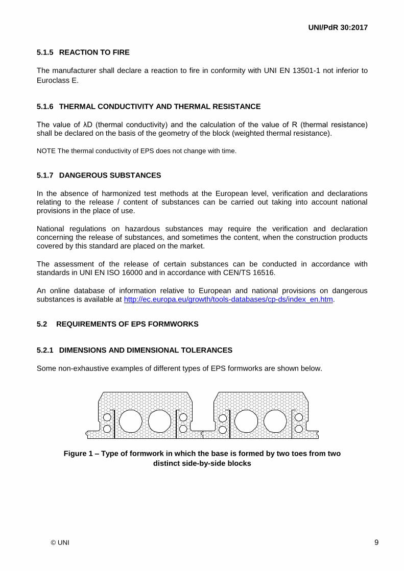
Some non-exhaustive examples of different types of EPS formworks are shown below.
Figure 1 – Type of formwork in which the base is formed by two toes from two
distinct side-by-side blocks
UNI/PdR 30:2017
© UNI 10
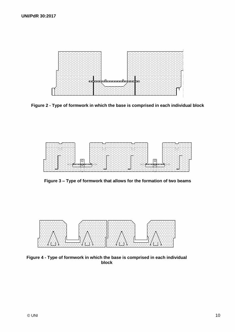
Figure 2 - Type of formwork in which the base is comprised in each individual block
Figure 3 – Type of formwork that allows for the formation of two beams
Figure 4 - Type of formwork in which the base is comprised in each individual block
UNI/PdR 30:2017
© UNI 11
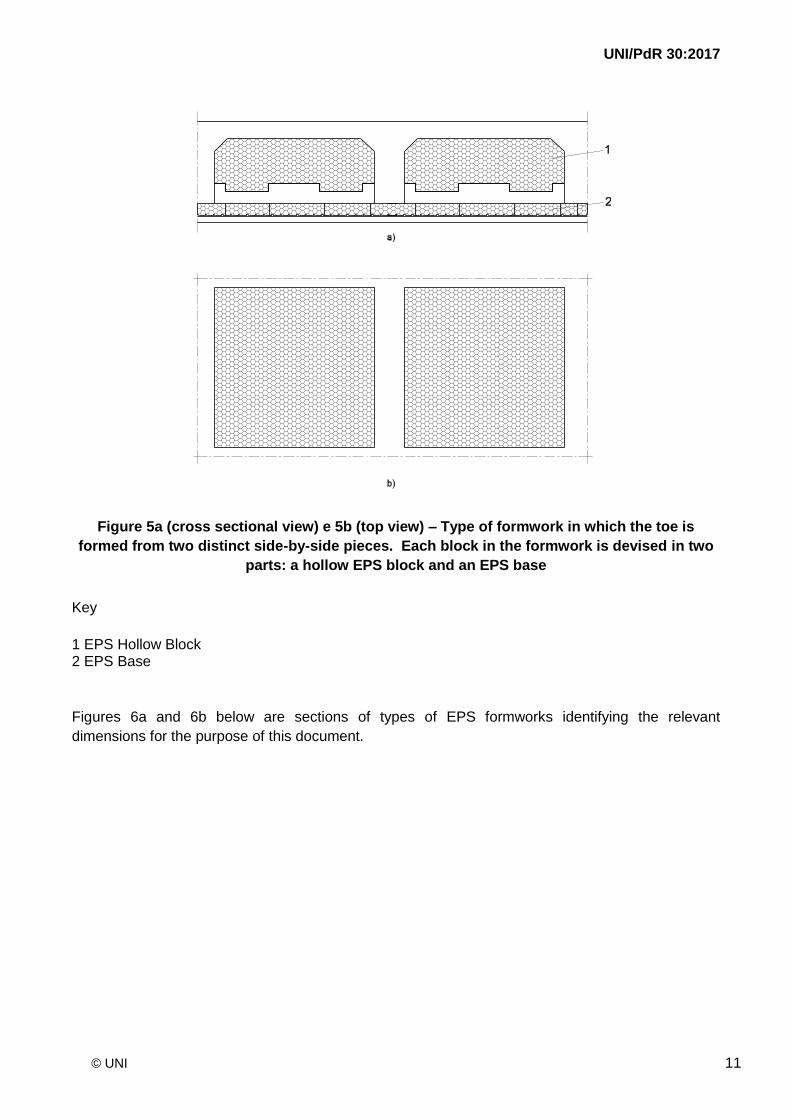
Figure 5a (cross sectional view) e 5b (top view) – Type of formwork in which the toe is
formed from two distinct side-by-side pieces. Each block in the formwork is devised in two
parts: a hollow EPS block and an EPS base
Key
1 EPS Hollow Block 2 EPS Base
Figures 6a and 6b below are sections of types of EPS formworks identifying the relevant
dimensions for the purpose of this document.
UNI/PdR 30:2017
© UNI 12
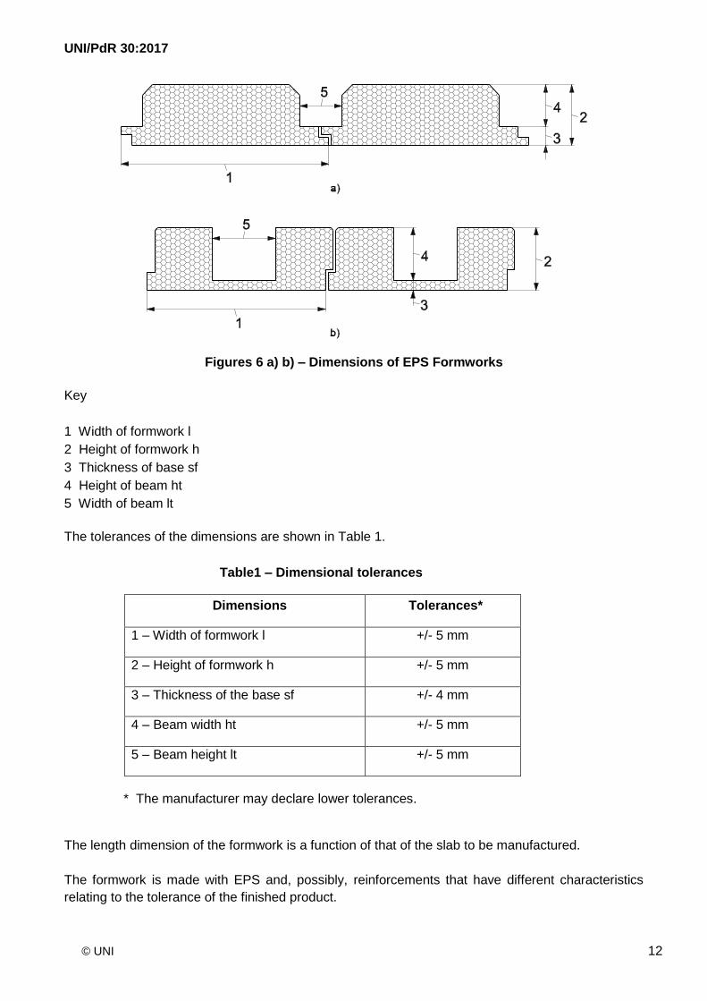
Figures 6 a) b) – Dimensions of EPS Formworks
Key
1 Width of formwork l
2 Height of formwork h
3 Thickness of base sf
4 Height of beam ht
5 Width of beam lt
The tolerances of the dimensions are shown in Table 1.
Table1 – Dimensional tolerances
Dimensions Tolerances*
1 – Width of formwork l +/- 5 mm
2 – Height of formwork h +/- 5 mm
3 – Thickness of the base sf +/- 4 mm
4 – Beam width ht +/- 5 mm
5 – Beam height lt +/- 5 mm
* The manufacturer may declare lower tolerances.
The length dimension of the formwork is a function of that of the slab to be manufactured.
The formwork is made with EPS and, possibly, reinforcements that have different characteristics
relating to the tolerance of the finished product.
UNI/PdR 30:2017
© UNI 13
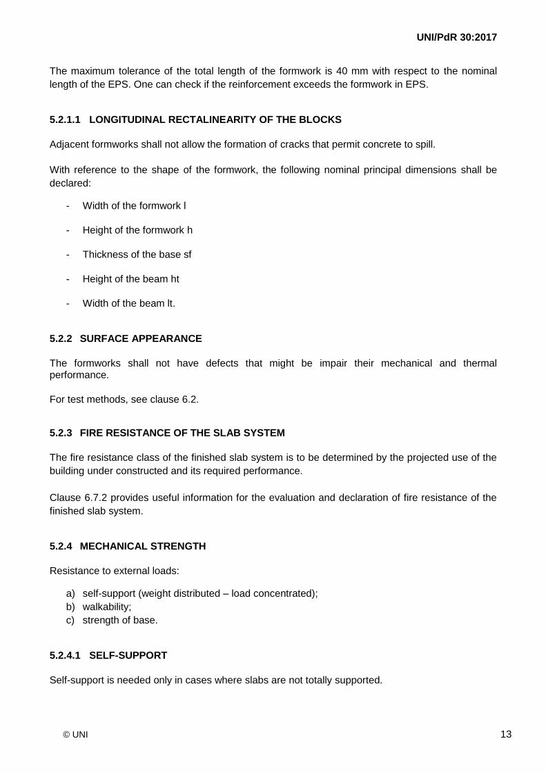
The maximum tolerance of the total length of the formwork is 40 mm with respect to the nominal
length of the EPS. One can check if the reinforcement exceeds the formwork in EPS.
5.2.1.1 LONGITUDINAL RECTALINEARITY OF THE BLOCKS
Adjacent formworks shall not allow the formation of cracks that permit concrete to spill.
With reference to the shape of the formwork, the following nominal principal dimensions shall be
declared:
- Width of the formwork l
- Height of the formwork h
- Thickness of the base sf
- Height of the beam ht
- Width of the beam lt.
5.2.2 SURFACE APPEARANCE
The formworks shall not have defects that might be impair their mechanical and thermal performance.
For test methods, see clause 6.2.
5.2.3 FIRE RESISTANCE OF THE SLAB SYSTEM
The fire resistance class of the finished slab system is to be determined by the projected use of the
building under constructed and its required performance.
Clause 6.7.2 provides useful information for the evaluation and declaration of fire resistance of the
finished slab system.
5.2.4 MECHANICAL STRENGTH
Resistance to external loads:
a) self-support (weight distributed – load concentrated);
b) walkability;
c) strength of base.
5.2.4.1 SELF-SUPPORT
Self-support is needed only in cases where slabs are not totally supported.
UNI/PdR 30:2017
© UNI 14
The self-supporting panels shall be able to withstand the loads at the initial construction stage, i.e., fresh concrete, reinforcing rods, and workers, as provided for by UNI EN 1994-1-1.
The test is carried out as described in clause 6.9.1 to verify the deformation deflection caused by agent loads defined according to the actual use and distance between supporting purlins. 5.2.4.2 WALKABILITY
Walkability is measured by the resistance to concentrated loads, PRK.
The minimum resistance to PRK concentrated loads shall be not less than 1.5 KN value (for the 5%
fractile) and is evaluated according to the test described in clause 6.9.2 (test load focused on a
single block).
5.2.4.3 STRENGTH OF THE TOE/BASE BEAM
The strength of the toe/base beam shall be evaluated by a load test in which an appropriate
equivalent load simulates the load that shall supported by the work in progress (the poured concrete
and iron reinforcement).
The test method is specified in clause 6.9.3. The test is passed if the breaking point of the toe/base
is not reached with an appropriately-determined equivalent load.
5.2.5 THERMAL RESISTANCE OF THE SLAB
To calculate the thermal resistance of the slab (R value), the equivalent λ value shall be used. One method is shown in clause 6.8. Another method can be used, provided that the results are equivalent.
5.2.6 ACOUSTIC PROPERTIES
The acoustic properties depend on the finished slab (type of formwork, elements applied to the inferior and superior surfaces of the slab, etc.)
Where pertinent, clause 4.3.5 of UNI EN 13369:2004 should be applied.
NOTE For design purposes, and in the absence of measurement results, the method shown in Appendix L of UNI EN 15037-1:2008 shall be used (sound insulation from impacts and airborne noise).
5.2.7 DURABILITY
The durability of the formwork shall be consistent with the materials used for the construction of the slab.
UNI/PdR 30:2017
© UNI 15
6 TEST METHODS
6.1 DIMENSIONS OF EPS FORMWORKS
Dimensions shall meet the requirements and values declared by the manufacturer within the
tolerances specified in clause 5.2.1.
The following are the principal nominal dimensions:
- formwork width l
- formwork height h
- thickness of the base sf
- beam height ht
- beam width lt.
Dimensions shall be checked at least once for each order.
6.2 SURFACE APPEARANCE
The surface appearance of the blocks shall be visually inspected. Defective products shall be discarded.
6.3 COMPRESSIVE STRENGTH
The compressive strength of the EPS shall be determined in accordance with UNI EN 826.
6.4 FLEXURAL STRENGTH
The flexural strength of the EPS shall be determined in accordance with UNI EN 12089.
6.5 WATER ABSORPTION
The water absorption of the EPS shall be determined in accordance with UNI EN 1609 for
absorption after partial immersion for a short period (24 h).
6.6 PERMEABILITY TO WATER VAPOUR
The factor of resistance to water vapour diffusion in EPS, μ, shall be determined according to UNI
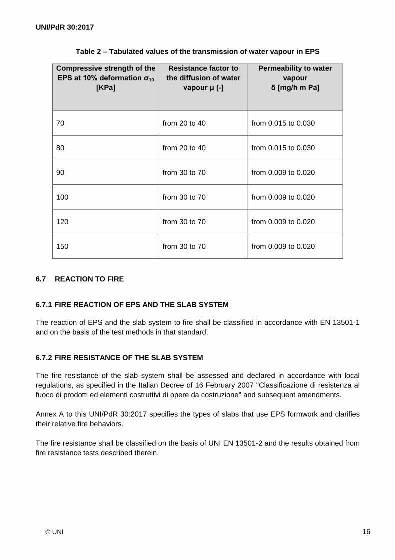
EN 12086 or found from tabulated values specifically reported in EN 13163, as follows:
UNI/PdR 30:2017
© UNI 16
Table 2 – Tabulated values of the transmission of water vapour in EPS
Compressive strength of the
EPS at 10% deformation σ10
[KPa]
Resistance factor to
the diffusion of water
vapour μ [-]
Permeability to water
vapour
δ [mg/h m Pa]
70 from 20 to 40 from 0.015 to 0.030
80 from 20 to 40 from 0.015 to 0.030
90 from 30 to 70 from 0.009 to 0.020
100 from 30 to 70 from 0.009 to 0.020
120 from 30 to 70 from 0.009 to 0.020
150 from 30 to 70 from 0.009 to 0.020
6.7 REACTION TO FIRE
6.7.1 FIRE REACTION OF EPS AND THE SLAB SYSTEM
The reaction of EPS and the slab system to fire shall be classified in accordance with EN 13501-1
and on the basis of the test methods in that standard.
6.7.2 FIRE RESISTANCE OF THE SLAB SYSTEM
The fire resistance of the slab system shall be assessed and declared in accordance with local
regulations, as specified in the Italian Decree of 16 February 2007 "Classificazione di resistenza al
fuoco di prodotti ed elementi costruttivi di opere da costruzione" and subsequent amendments.
Annex A to this UNI/PdR 30:2017 specifies the types of slabs that use EPS formwork and clarifies
their relative fire behaviors.
The fire resistance shall be classified on the basis of UNI EN 13501-2 and the results obtained from
fire resistance tests described therein.
UNI/PdR 30:2017
© UNI 17
6.8 THERMAL PROPERTIES
6.8.1 THERMAL CONDUCTIVITY
Thermal conductivity shall be measured in conformity with clause 4.2.1 of UNI EN 13163 and UNI
EN 12667.
6.8.2 THERMAL RESISTANCE OF THE SLAB
The thermal resistance of the slab is determined by calculations. The method used shall satisfy the
requirements of EN ISO 10211.
6.9 MECHANICAL RESISTANCE
6.9.1 SELF-SUPPORT
The evaluation and testing of the self-supporting capacity of the EPS formwork under loads
corresponding to the phase of pouring the concrete and the related actions of external agents is
done according to the test methods indicated below.
The corresponding load test is used to in order to verify:
- the permanent deflection due to its own weight and corresponding to the phase of the
concrete pour.
- the load-bearing capacity of the slab formwork against possible loads acting on the structure
during the pour;
- the failure mechanism leading to collapse of the formwork.
The EPS formwork is placed on two supports that are placed at a distance that simulates the most
unfavourable condition in which that element that will be found during construction.
Two centesimal gauges are positioned on the unloaded structure, one on the centerline (M1) and
the other on the support to the right (M2).
The first step is performed with a uniformly distributed load over the entire span (Figure 7).
UNI/PdR 30:2017
© UNI 18
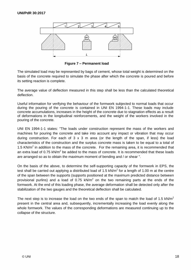
Figure 7 – Permanent load The simulated load may be represented by bags of cement, whose total weight is determined on the
basis of the concrete required to simulate the phase after which the concrete is poured and before
its setting reaction is complete.
The average value of deflection measured in this step shall be less than the calculated theoretical
deflection.
Useful information for verifying the behaviour of the formwork subjected to normal loads that occur during the pouring of the concrete is contained in UNI EN 1994-1-1. These loads may include concrete accumulations, increases in the height of the concrete due to stagnation effects as a result of deformations in the longitudinal reinforcements, and the weight of the workers involved in the pouring of the concrete.
UNI EN 1994-1-1 states: "The loads under construction represent the mass of the workers and
machines for pouring the concrete and take into account any impact or vibration that may occur
during construction. For each of 3 x 3 m area (or the length of the span, if less) the load
characteristics of the construction and the surplus concrete mass is taken to be equal to a total of
1.5 KN/m2 in addition to the mass of the concrete. For the remaining area, it is recommended that
an extra load of 0.75 kN/m2 be added to the mass of concrete. It is recommended that these loads
are arranged so as to obtain the maximum moment of bending and / or shear ".
On the basis of the above, to determine the self-supporting capacity of the formwork in EPS, the
test shall be carried out applying a distributed load of 1.5 kN/m2 for a length of 1.00 m at the centre
of the span between the supports (supports positioned at the maximum predicted distance between
provisional purlins) and a load of 0.75 kN/m2 on the two remaining parts at the ends of the
formwork. At the end of this loading phase, the average deformation shall be detected only after the
stabilization of the two gauges and the theoretical deflection shall be calculated.
The next step is to increase the load on the two ends of the span to match the load of 1.5 kN/m2
present in the central area and, subsequently, incrementally increasing the load evenly along the
whole formwork. The values of the corresponding deformations are measured continuing up to the
collapse of the structure.
UNI/PdR 30:2017
© UNI 19
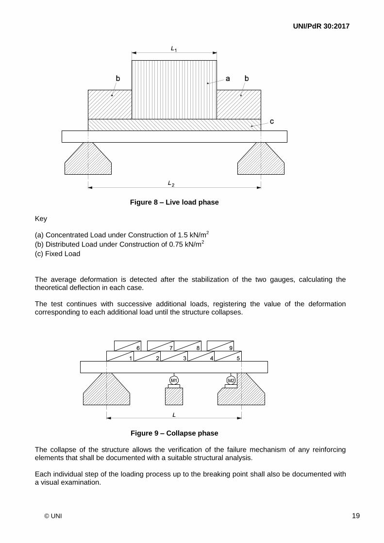
Figure 8 – Live load phase Key (a) Concentrated Load under Construction of 1.5 kN/m2
(b) Distributed Load under Construction of 0.75 kN/m2
(c) Fixed Load
The average deformation is detected after the stabilization of the two gauges, calculating the theoretical deflection in each case. The test continues with successive additional loads, registering the value of the deformation corresponding to each additional load until the structure collapses.
Figure 9 – Collapse phase The collapse of the structure allows the verification of the failure mechanism of any reinforcing elements that shall be documented with a suitable structural analysis. Each individual step of the loading process up to the breaking point shall also be documented with a visual examination.
UNI/PdR 30:2017
© UNI 20
6.9.2 WALKABILITY
6.9.2.1 TEST APPARATUS
- Test apparatus of at least class 3 for the application for forces specified in UNI EN 12390-
4:2000;
- Framework sufficiently rigid to withstand the forces applied while loading the test object;
- Supports: the two supports represent the beams. One support shall be fixed and the other
adjustable. If continuous support (formwork) is required by local regulations, that can also be
used.
NOTE The two supports can be covered with abrasive cloth (40 grit) or a system that has an equivalent roughness. The abrasive cloth covers the actual length of and adheres to the supports. It can be cleaned and replaced regularly, at the discretion of the manufacturer.
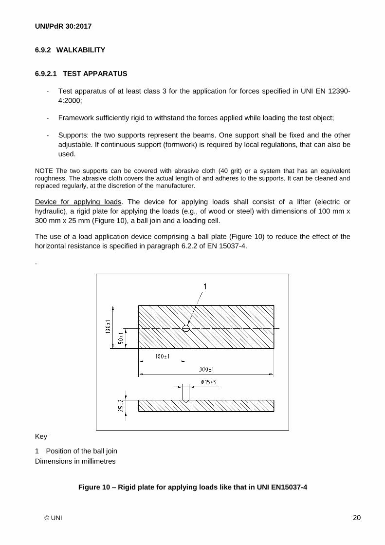
Device for applying loads. The device for applying loads shall consist of a lifter (electric or
hydraulic), a rigid plate for applying the loads (e.g., of wood or steel) with dimensions of 100 mm x
300 mm x 25 mm (Figure 10), a ball join and a loading cell.
The use of a load application device comprising a ball plate (Figure 10) to reduce the effect of the
horizontal resistance is specified in paragraph 6.2.2 of EN 15037-4.
.
Key
1 Position of the ball join
Dimensions in millimetres
Figure 10 – Rigid plate for applying loads like that in UNI EN15037-4
UNI/PdR 30:2017
© UNI 21
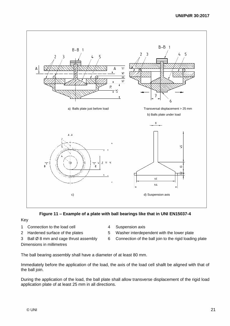
a) Balls plate just before load Transversal displacement > 25 mm
b) Balls plate under load
c) d) Suspension axis
Figure 11 – Example of a plate with ball bearings like that in UNI EN15037-4
Key
1 Connection to the load cell 4 Suspension axis
2 Hardened surface of the plates 5 Washer interdependent with the lower plate
3 Ball Ø 8 mm and cage thrust assembly 6 Connection of the ball join to the rigid loading plate
Dimensions in millimetres
The ball bearing assembly shall have a diameter of at least 80 mm. Immediately before the application of the load, the axis of the load cell shallt be aligned with that of the ball join. During the application of the load, the ball plate shall allow transverse displacement of the rigid load application plate of at least 25 mm in all directions.
UNI/PdR 30:2017
© UNI 22
Calibration: The resistance results obtained from the test apparatus described in section 6.2.1 of EN 15037-4 (with or without a ball plate) shall be multiplied by a default calibration factor C1 as follows:
- 0.95 when the tests are carried out with a ball plate in conformity with clause 5.2.1; - 0.85 when the tests are carried out without a ball plate.
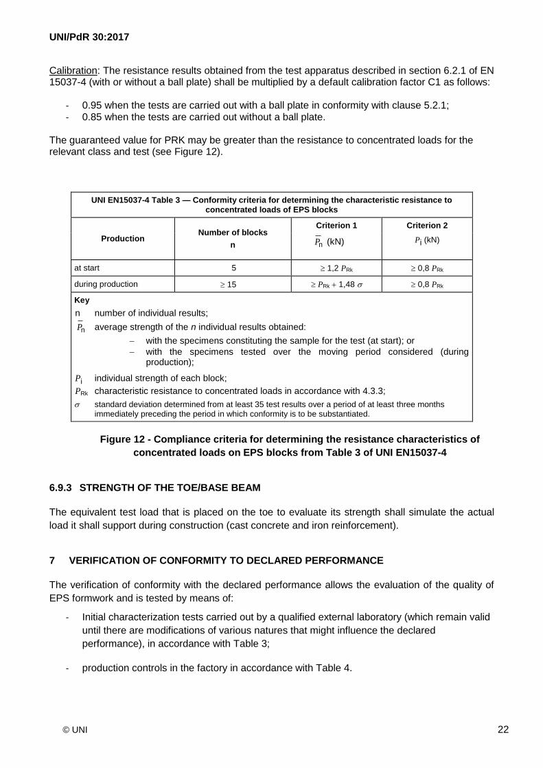
The guaranteed value for PRK may be greater than the resistance to concentrated loads for the relevant class and test (see Figure 12).
UNI EN15037-4 Table 3 — Conformity criteria for determining the characteristic resistance to
concentrated loads of EPS blocks
Production Number of blocks
n
Criterion 1 Criterion 2
nP (kN) Pi (kN)
at start 5 1,2 PRk 0,8 PRk
during production 15 PRk 1,48 0,8 PRk
Key
n number of individual results;
nP average strength of the n individual results obtained:
with the specimens constituting the sample for the test (at start); or
with the specimens tested over the moving period considered (during production);
Pi individual strength of each block;
PRk characteristic resistance to concentrated loads in accordance with 4.3.3;
standard deviation determined from at least 35 test results over a period of at least three months immediately preceding the period in which conformity is to be substantiated.
Figure 12 - Compliance criteria for determining the resistance characteristics of
concentrated loads on EPS blocks from Table 3 of UNI EN15037-4
6.9.3 STRENGTH OF THE TOE/BASE BEAM
The equivalent test load that is placed on the toe to evaluate its strength shall simulate the actual
load it shall support during construction (cast concrete and iron reinforcement).
7 VERIFICATION OF CONFORMITY TO DECLARED PERFORMANCE
The verification of conformity with the declared performance allows the evaluation of the quality of
EPS formwork and is tested by means of:
- Initial characterization tests carried out by a qualified external laboratory (which remain valid
until there are modifications of various natures that might influence the declared
performance), in accordance with Table 3;
- production controls in the factory in accordance with Table 4.
UNI/PdR 30:2017
© UNI 23
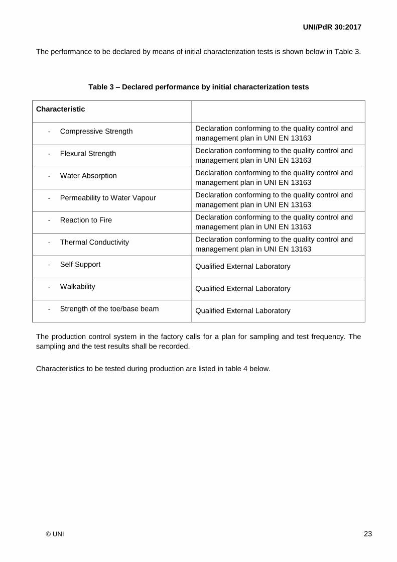
The performance to be declared by means of initial characterization tests is shown below in Table 3.
Table 3 – Declared performance by initial characterization tests
Characteristic
- Compressive Strength Declaration conforming to the quality control and
management plan in UNI EN 13163
- Flexural Strength Declaration conforming to the quality control and
management plan in UNI EN 13163
- Water Absorption Declaration conforming to the quality control and
management plan in UNI EN 13163
- Permeability to Water Vapour Declaration conforming to the quality control and
management plan in UNI EN 13163
- Reaction to Fire Declaration conforming to the quality control and
management plan in UNI EN 13163
- Thermal Conductivity Declaration conforming to the quality control and
management plan in UNI EN 13163
- Self Support Qualified External Laboratory
- Walkability Qualified External Laboratory
- Strength of the toe/base beam Qualified External Laboratory
The production control system in the factory calls for a plan for sampling and test frequency. The
sampling and the test results shall be recorded.
Characteristics to be tested during production are listed in table 4 below.
UNI/PdR 30:2017
© UNI 24
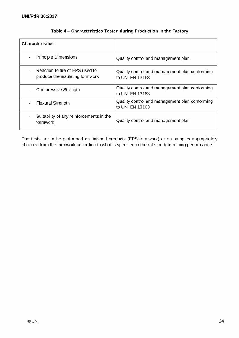
Table 4 – Characteristics Tested during Production in the Factory
Characteristics
- Principle Dimensions Quality control and management plan
- Reaction to fire of EPS used to
produce the insulating formwork Quality control and management plan conforming
to UNI EN 13163
- Compressive Strength Quality control and management plan conforming
to UNI EN 13163
- Flexural Strength Quality control and management plan conforming
to UNI EN 13163
- Suitability of any reinforcements in the
formwork Quality control and management plan
The tests are to be performed on finished products (EPS formwork) or on samples appropriately
obtained from the formwork according to what is specified in the rule for determining performance.
UNI/PdR 30:2017
© UNI 25
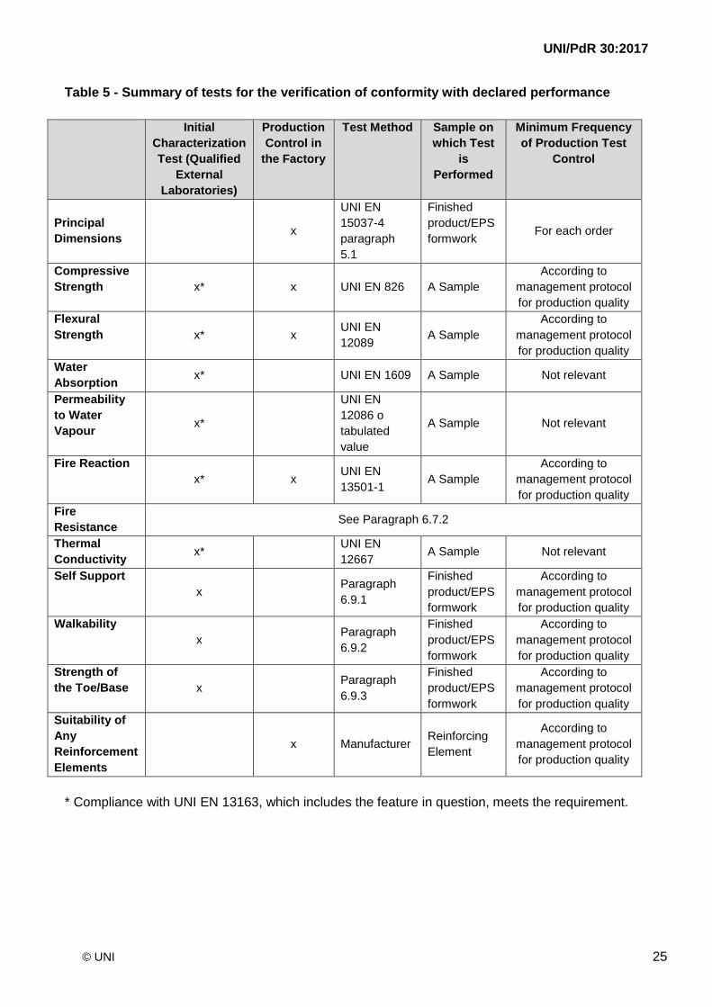
Table 5 - Summary of tests for the verification of conformity with declared performance
Initial
Characterization
Test (Qualified
External
Laboratories)
Production
Control in
the Factory
Test Method Sample on
which Test
is
Performed
Minimum Frequency
of Production Test
Control
Principal
Dimensions x
UNI EN
15037-4
paragraph
5.1
Finished
product/EPS
formwork For each order
Compressive
Strength x* x UNI EN 826 A Sample
According to
management protocol
for production quality
Flexural
Strength x* x UNI EN
12089 A Sample
According to
management protocol
for production quality
Water
Absorption x* UNI EN 1609 A Sample Not relevant
Permeability
to Water
Vapour x*
UNI EN
12086 o
tabulated
value
A Sample Not relevant
Fire Reaction
x* x UNI EN
13501-1 A Sample
According to
management protocol
for production quality
Fire
Resistance See Paragraph 6.7.2
Thermal
Conductivity x*
UNI EN
12667 A Sample Not relevant
Self Support
x Paragraph
6.9.1
Finished
product/EPS
formwork
According to
management protocol
for production quality
Walkability
x Paragraph
6.9.2
Finished
product/EPS
formwork
According to
management protocol
for production quality
Strength of
the Toe/Base x Paragraph
6.9.3
Finished
product/EPS
formwork
According to
management protocol
for production quality
Suitability of
Any
Reinforcement
Elements
x Manufacturer Reinforcing
Element
According to
management protocol
for production quality
* Compliance with UNI EN 13163, which includes the feature in question, meets the requirement.
UNI/PdR 30:2017
© UNI 26
APPENDIX – REACTION TO FIRE OF LIGHTWEIGHT SLAB SYSTEMS
The types of slabs that are present in the market made with EPS formworks can be divided into two
major groups:
- slabs with a lower finish of reinforced concrete;
- slabs without a lower finish of reinforced concrete.
The systems that are the subject of this UNI/PdR belong to the second group.
NOTE Any pressure relief vents are provided for only in the case the slab is made with a lower finish of
reinforced concrete of 4-5 cm thickness.
In cases in which the slab does not have such a finish, pressure relief vents are not necessary.
Slabs made with SAAD systems covered by this UNI/PdR 30:2017 do not have lower finishes of
reinforced concrete and, for that reason, do not require such a design feature, as stated in the note
from the Ministry of the Interior (Prot. N ° P599 / 4122 sott.55) of 26 July 2006.