Embed Size (px)
DESCRIPTION
In this paper, we present the theory and design of a novel microwave active notch filter operating at X-band (8 GHz-12.4 GHz). The notch filter has a notch frequency of 10.22 GHz and a 3 dB calculated bandwidth of 87 MHz, the corresponding 3 dB experimental bandwidth is 120 MHz. The filter is designed using a magic tee and two tunable X-band Gunn oscillators injection-locked to the input interference to be eliminated. The special features of this filter are that it is of low noise, tunable and signal tracking character and possesses considerable power handling capacity.
Citation preview
http://www.iaeme.com/IJECET/index.asp 25 [email protected]
International Journal of Electronics and Communication Engineering & Technology
(IJECET)
Volume 7, Issue 2, March-April 2016, pp. 25-32, Article ID: IJECET_07_02_004
Available online at
http://www.iaeme.com/IJECET/issues.asp?JType=IJECET&VType=7&IType=2
Journal Impact Factor (2016): 8.2691 (Calculated by GISI) www.jifactor.com
ISSN Print: 0976-6464 and ISSN Online: 0976-6472
© IAEME Publication
UNILATERALLY INJECTION-LOCKED
GUNN OSCILLATOR PAIR ACTING AS A
MICROWAVE ACTIVE NOTCH FILTER
Santosh Kumar Dawn
Dept. of Physics, Viva-Bharati, Santiniketan, West-Bengal, India
Taraprasad Chattopadhyay
Dept. of Physics, Visva-Bharati, Santiniketan, West-Bengal, India
ABSTRACT
In this paper, we present the theory and design of a novel microwave
active notch filter operating at X-band (8 GHz-12.4 GHz). The notch filter has
a notch frequency of 10.22 GHz and a 3 dB calculated bandwidth of 87 MHz,
the corresponding 3 dB experimental bandwidth is 120 MHz. The filter is
designed using a magic tee and two tunable X-band Gunn oscillators
injection-locked to the input interference to be eliminated. The special features
of this filter are that it is of low noise, tunable and signal tracking character
and possesses considerable power handling capacity.
Key words: Gunn Oscillator, Injection locking, Microwave, Notch filter,
Notch Frequency.
Cite this Article: Santosh Kumar Dawn and Taraprasad Chattopadhyay.
Unilaterally Injection-Locked Gunn Oscillator Pair Acting As A Microwave
Active Notch Filter, International Journal of Electronics and Communication
Engineering & Technology, 7(2), 2016, pp. 25-32.
http://www.iaeme.com/IJECET/issues.asp?JType=IJECET&VType=7&IType=2
1. INTRODUCTION
Notch filters are essential components of a microwave communication system.
Microwaves, according to IEEE convention, span over the frequency range 3 GHz-30
GHz of the electromagnetic spectrum. Notch filters are used to eliminate monotone or
narrowband interference in a receiver. This interference can appear automatically
from adjacent channels and it can also be man-made when the interference is
introduced deliberately for jamming a communication receiver. A good notch filter
must have low insertion loss, negligible radiation loss and high power handling
capacity which are of major concern at microwave frequencies. A notch filter can be
treated as a special case of band reject filter where the stop band becomes very narrow
Santosh Kumar Dawn and Taraprasad Chattopadhyay
http://www.iaeme.com/IJECET/index.asp 26 [email protected]
and the attenuation becomes high. Design of microwave notch filters [1-6] is being
investigated over a few decades. To make the notch filters reconfigurable and to
operate at higher microwave frequencies, research work is going on the design of
notch filter all over the globe till now. Jackowski et al., have proposed a frequency
agile, constant bandwidth, reconfigurable notch filter with a tuning range of an octave
[7, 8]. A notch filter has been designed at 13.2 GHz with a bandwidth of 50 MHz and
25 dB rejection at the notch frequency by Narayana et al., . Notch filters have been
designed [10] using Barium strontium Titanate thin film varactor technology by
Ramadugu.
The low frequency notch filter discussed above are all passive, in general. Active
notch filters [4-6] incorporate one or more amplifying devices such as negative
resistance oscillators. These negative resistance oscillators when operated in the
injection-locked mode possess amplitude noise reduction property as well as higher
power handling capacity.
In this paper, we have used a pair of unilaterally injection locked Gunn oscillator
operating at X-band. The Gunn oscillators are locked to the input interference
received at the receiver and follows the interfering signal. The Gunn oscillator pair is
thus made coherent and their outputs are subtracted at the E-arm of the magic tee
resulting in a cancellation of the interference accompanying the input signal assuming
the Gunn oscillator pair to be identical. The desired signal falls outside the rejection
band of the notch filter and passes through it.
2. MECHANISM OF OPERATION
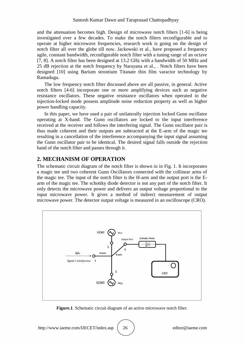
The schematic circuit diagram of the notch filter is shown in in Fig. 1. It incorporates
a magic tee and two coherent Gunn Oscillators connected with the collinear arms of
the magic tee. The input of the notch filter is the H-arm and the output port is the E-
arm of the magic tee. The schottky diode detector is not any part of the notch filter. It
only detects the microwave power and delivers an output voltage proportional to the
input microwave power. It gives a method of indirect measurement of output
microwave power. The detector output voltage is measured in an oscilloscope (CRO).
Figure.1. Schematic circuit diagram of an active microwave notch filter.
Unilaterally Injection-Locked Gunn Oscillator Pair Acting as a Microwave Active Notch
Filter
http://www.iaeme.com/IJECET/index.asp 27 [email protected]
3. ANALYSIS
For injection locking at microwave frequencies, there must exist a free running
microwave oscillator, called the slave oscillator, which is injected by the output power
of another microwave oscillator, called as the master oscillator. Depending upon the
frequency detuning of the injection signal frequency from the free running slave
oscillator frequency and the relative power of the injection signal, the slave oscillator
gets injection locked to the master oscillator. Under locked condition, the slave
oscillator frequency becomes identical with that of the master oscillator and the input-
output phase error assumes a constant value. If the injection signal power is much less
than the free running slave oscillator power, the latter is said to be under driven. On
the other hand, the locked oscillator is said to be overdriven if the injection signal
power is comparable or greater than the free running slave oscillator output power.
The injection locked Gunn oscillators (GO#2 and GO#3) have amplitude limiting
property. Any amplitude modulation of the injection signal is shaked-off by the
locked oscillators. So, we will not use amplitude modulation as modulation format of
the input signal. Rather, we will consider FM signal input and study the response of
the sub-system to such frequency modulated signal. The interference to be removed
from the receiver is assumed to be monotone in nature.
We will make a static analysis of the sub-system considering a slow variation of
input master signal frequency. The input signal is delivered by a tunable Gunn
oscillator (not shown in Fig. 1). Let the microwave voltage of the input signal be
written as
tVtv 111 sin)( (1)
where 1V is the voltage amplitude and 1 is the radian frequency. The injection
signal voltage to Gunn oscillators (GO#2 and GO#3) is obtained through half-power
division of the input signal at the magic tee junction and is given by2
)(1 tv.
The Gunn oscillator GO#2 and GO#3 are taken of the same type which oscillate at
the same microwave frequency. The voltages of the free-running GO#2 and GO#3 are
described by the equations
tVtv f 0222 sin)( (2)
and tVtv f 0333 sin)( (3)
respectively. Here, 0302 where 02 and 03 are the radian frequencies of the
Gunn oscillators GO#2 and GO#3 respectively. The free running output powers are
2fP and 3fP where 2
22 ff VP and 2
33 ff VP respectively. The output voltages of the
injection-locked Gunn oscillators are assumed to be of the form
)(sin)( 1 iii tVtv (4)
for i = 2, 3. iV is the voltage amplitude and i is the input-output phase error of
the i- th slave Gunn Oscillator. Neglecting any asymmetry in locking, the phase
equation of the injected Gunn oscillator (GO#2 and GO#3) are given [11] by
Santosh Kumar Dawn and Taraprasad Chattopadhyay
http://www.iaeme.com/IJECET/index.asp 28 [email protected]
)(sin22
0
1
0
0
10 tP
P
Qdt
di
oi
inj
Li
ii
i
ii
(5)
for i = 2, 3. )(ti is the input-output phase error for the i- th Gunn oscillator, LiQ
is the loaded Q-factor and oiP is the output power of the i- th injection locked Gunn
oscillator. Under steady state condition of locking, 0)(
dt
td i. Then,
i
i
inj
oiLii
P
PQ
0
012sin
(6)
assuming ii 001 2 and 2
ioi VP is the output power of the i-th locked
oscillator. The amplitude governing equations [11] of the injected Gunn oscillators are
written as
i
i
inj
Li
i
Li
iii
i
P
P
Raa
dt
da
cos
221
0
0012 (7)
where i=2,3 and fi
ii
V
Va . The parameter
L
Ld
R
RRRR
1 . Here dR is the
magnitude of the negative resistance of the Gunn diode, R is the cavity resistance and
LR is the load resistance. In the steady state of locking, 0dt
dai . The frequency
response of the injected Gunn oscillator is obtained by eliminating i from (5) and
(6) with 0dt
dai as
201
2
0
2
1
222
0
21 i
i
Liii
i
inj QRaa
P
P
(8)
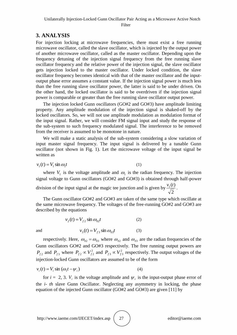
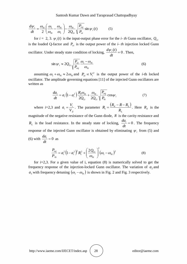
for i=2,3. For a given value of i, equation (8) is numerically solved to get the
frequency response of the injection-locked Gunn oscillator. The variation of 2a and
3a with frequency detuning i01 is shown in Fig. 2 and Fig. 3 respectively.
Unilaterally Injection-Locked Gunn Oscillator Pair Acting as a Microwave Active Notch
Filter
http://www.iaeme.com/IJECET/index.asp 29 [email protected]
Figure. 2. Plot of 2a with Frequency detuning
021
Figure. 3. Plot of 3a with frequency detuning
031
Using the scattering matrix of the magic tee [11], the total input voltage of the
Schottky diode detector connected with arm-4 (E-arm) of the magic tee is expressed
as
i
i
iDin t
vtv
1
3,2
sin2
)( (9)
The detector characteristics as obtained from earlier work [11] is expressed as
2
2
)(tv
Pv
Din
inDout
(10)
where Doutv is the detector output voltage, )(tvDin is the effective microwave input
voltage of the diode detector, inP is the input microwave power of the diode detector
and is the responsively of the detector. From equation (9), we can write
3232
2
3
2
2
2cos
2
1
4
1)( vvvvtvDin (11)
Santosh Kumar Dawn and Taraprasad Chattopadhyay
http://www.iaeme.com/IJECET/index.asp 30 [email protected]
Under locked condition, both GO#2 and GO#3 have the same oscillation
frequency, 1 . The injection power is same for both the Gunn oscillators GO#2
andGO#3. When 32 ,
232
2
max 4
1)( VVtvDiun (12)
This gives the maximum output voltage of the detector. The detector is not a part
of notch filter. It is only used to measure the output power of the notch filter in terms
of voltage. The normalized output power of the notch filter using equation (10) is
given by
232
3232
2
32
2
.max
2
cos2
)(
)(
VV
VVVV
tv
tv
Dout
Dout
=
3232
2
33
2
22
323232
2
33
2
22
2
cos2
ffff
ffff
PPaaaPaP
PPaaaPaP
(13)
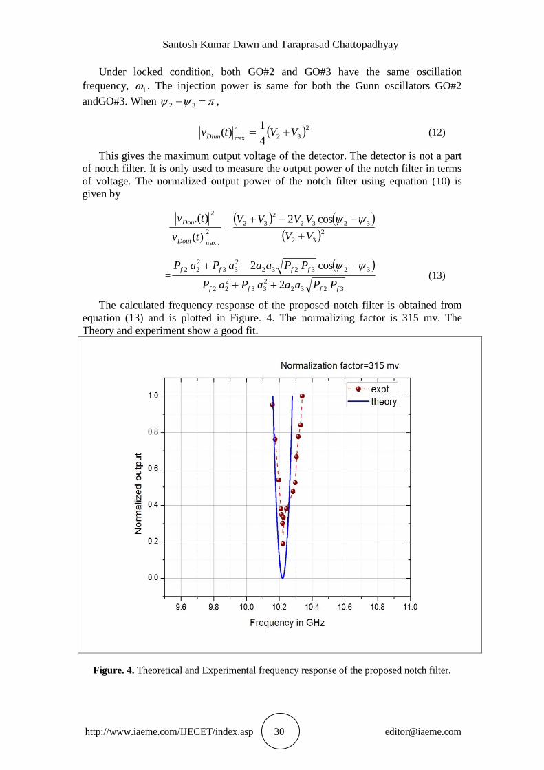
The calculated frequency response of the proposed notch filter is obtained from
equation (13) and is plotted in Figure. 4. The normalizing factor is 315 mv. The
Theory and experiment show a good fit.
Figure. 4. Theoretical and Experimental frequency response of the proposed notch filter.
Unilaterally Injection-Locked Gunn Oscillator Pair Acting as a Microwave Active Notch
Filter
http://www.iaeme.com/IJECET/index.asp 31 [email protected]
4. EXPERIMENT
The Gunn oscillators having model no. XG-11 have been procured from M/S SICO
Ltd; India. Magic tee and directional couples used for microwave power measurement
and variable attenuator for input signal power attenuation have been purchased from
M/S Vidyut Yantra Udyog Limited, India. Schottky barrier diode and the microwave
power meter have been procured from M/S Salicon Nanotechnology Limited, India.
The measured lock band for Gunn oscillator GO#2 with free running frequency of
10.22 GHz and free running power of 8.75 mW is 118 MHz for an injection power of
4.25 mW. This corresponds to a loaded Q factor. QL=60. GO#3 has a free running
power of 7.5 mW at the free running frequency of 10.22 GHz. It has a Q-value of 59.
The notch Frequency can be tuned by tuning the free running frequencies of slave
oscillators GO#2 and GO#3.
5. CONCLUSION
The theory and design of an active microwave notch filter has been presented in this
paper. The notch frequency is 10.22 GHz with a 3-dB experimental bandwidth of 120
MHz. This filter has negligible insertion loss and considerable power handling
capacity. Besides, since injection locking has been used in the design, the notch filter
will strongly reduce amplitude noise [11] of the received signal. The notch filter has
also input signal tracking property.
6. REFERENCES
[1] I.C. Hunter and J.D. Rhodes, “Electronically tunable microwave band stop
filters”, IEEE Transactions on Microwave theory and Techniques, vol. MTT-30,
pp. 1361-1367, Sept. 1982.
[2] R. Levy, R.V. Snyder and G. Mathali, “Design of microwave filters”, IEEE
Transactions on Microwave theory and Techniques, vol. MTT-50, no. 3 pp. 783-
793, Mar 2002.
[3] T-Lin. Wu, “Microwave filter design”, Chap.6, Department of Electrical
Engineering, National Taiwan University, John Wiley & Sons, Inc., 2001.
[4] R.V Snyder, “Evaluation of of passive and active microwave filters”, Microwave
Symposium Digest, pp. 1-3, 2012.
[5] B.Y. Kapilevich, “Variety of approaches to designing microwave active filters”,
27 th European Microwave Conference, Jerusalem, Israel, vol. 1,pp.397-408, 8-
12 Sept. 1997.
[6] C.Y. Chang and T. Itoh, “Microwaves active filters based on coupled negative
resistance method”, IEEE Trans. On Microwave Theory and Techniques, vol.
MTT-38, no. 12, pp.1879-1884, Dec. 1990.
[7] D.R. Jackwoski and A.C. Guyette, “Sub-octave-tunable microstrip notch filter”,
IEEE EMC Society Symposium on Electromagnetic Compatibility, pp. 99-102,
Astin, Texas, VSA, Aug. 17-21, 2009.
[8] D.R. Jackwoski, “Passive enhancement of resonator Q in microwave notch
filters”, 2004 IEEE MTT-s International Microwave Symposium Digest, pp.
1315-1318, June 2004.
[9] M.S. Narayana and N. Gogia, “Accurate Design of a notch filter using
electromagnetic simulators”, Applied Microwave and Wireless, pp. 44-49, vol.
12,Part 11, 2000.
Santosh Kumar Dawn and Taraprasad Chattopadhyay
http://www.iaeme.com/IJECET/index.asp 32 [email protected]
[10] J.C. Ramadugu, Design of microwave bandstop and bandpass filters on Barium
Strontium Titanate thin film varactor technology”, Ph. D. Thesis, University of
Dayton, Dayton, Ohio, USA, Dec. 2013.
[11] Arvind Kumar, A Bhattacharya and D K Singh. Microwave Image
Reconstruction of Two Dimension Dielectric Scatterers Using Swarm Particle
Optimization, International Journal of Electronics and Communication
Engineering & Technology, 4(6), 2013, pp. 57-61.
[12] Prof. B.N. Biswas, S. Chatterjee and S Pal. Laser Induced Microwave Oscillator,
International Journal of Electronics and Communication Engineering &
Technology, 3(1), 2012, pp. 211 - 219.
[13] P. Bhattacharyya, S. K. Dawn and T. Chattopadhyay, “Low noise bandpass filter
using an X-band injection–locked Gunn oscillators”, International Journal of
Research in Engineering and Technology, vol. 04, issue-12, pp. 1-6, Dec. 2015.