Embed Size (px)
Citation preview
7232019 Unifying the Theory of Mutual Coupling Compensation in Antenna Arrays
httpslidepdfcomreaderfullunifying-the-theory-of-mutual-coupling-compensation-in-antenna-arrays 119
Unifying the Theory of Mutual Coupling
Compensation in Antenna Arrays
Simon Henault and Yahia M M Antar
Department of Electrical and Computer Engineering Royal Military College of Canada
Kingston ON K7K 7B4 CanadaE-mail henaultieeeorg
Abstract
The limitations of current mutual coupling compensation methods in antenna arrays are thoroughly reviewed Thetheory of mutual coupling compensation is unified in such a way that efficient methods can be employed for cali-brating both transmit and receive systems having arbitrary geometries The theory leads to methods that can eval-uate mutual coupling using either theoretical or experimental means Reciprocity is studied through the carefulcomparison of receive and transmit analytical formulations Examples involving various applications are presentedfor the validation of the theory This theory has numerous applications and contributes to the areas of antennatheory mutual coupling analysis complex structure modeling and antenna measurements
Keywords Antenna arrays mutual coupling calibration direction of arrival (DOA) estimation beam steering reciprocityretrodirective arrays
1 Introduction
Antenna arrays are employed in a variety of applications
including direction of arrival (DOA) estimation multiple-input multiple-output beam steering and interference sup-
pression In many cases accurate characterization of the array
response is critical in the optimization of the array perfor-
mance In particular the increasing use of arrays that consist
of relatively small numbers of closely spaced antenna ele-
ments or arrays that are located in the vicinity of scatterers
justi1047297es the requirement for mutual coupling compensation In
such systems electromagnetic coupling between the array
elements and scatterers results in nonuniform electromagnetic
responses from each of the array elements and degraded per-
formance if mutual coupling compensation is not per-
formed properly
Mutual coupling compensation can be performed either
by the prediction of received or transmitted signals for a
given excitation or by a matrix multiplication with the re-
ceived signals which restores the signals that would be re-
ceived in the absence of mutual coupling
As discussed in Section 2 of this paper various
methods have been presented in the literature for compensat-
ing mutual coupling in antenna arrays However many of
them appear to be restricted to speci1047297c array and element
geometries very often azimuth-only systems involving verti-
cal thin wire array elements Those that are applicable to
systems of arbitrary geometries appear to require excessive
amounts of measurements calculations and memory Unfor-
tunately no work has bridged the gap between ef 1047297cient
mutual coupling compensation methods and those that are
applicable to systems of arbitrary geometries This paper
proposes to do so by unifying the theory of mutual coupling
compensation
Going back to the basics of antenna theory in Section 3
useful analytical formulations will be derived as theoretical
foundations for unifying the theory Both receive and trans-mit antenna systems will be considered and clear reciprocity
relationships relating the two operating modes will be
highlighted giving new guidelines on mutual coupling com-
pensation in a system using data obtained for an operating
mode different from its intended one Techniques for improv-
ing mutual coupling compensation ef 1047297ciency will be pre-
sented in Section 4 and various applications of the theory
will be described in Section 5
This paper has potential value as both a review and a
tutorial paper and also presents new material The numerical Digital Object Identifier 101109MAP20152414514 Date of publication 20 April 2015
104 1045-924315$2600 copy 2015 IEEE IEEE Antennas and Propagation Magazine Vol 57 No 2 April 2015
7232019 Unifying the Theory of Mutual Coupling Compensation in Antenna Arrays
httpslidepdfcomreaderfullunifying-the-theory-of-mutual-coupling-compensation-in-antenna-arrays 219
examples can be easily veri1047297ed with proven electromagnetic
computational codes The use of receive-mode mutual cou-
pling compensation data in all examples even when the sys-
tems are employed in transmission is deliberate as mutual
coupling compensation is often performed using receive-
mode measurements and it provides additional validation
opportunities
2 Background
It was recently observed in [1] that although very differ-
ent coupling mechanisms for transmit and receive systems
have existed for quite some time in the literature many
researchers still prefer to analyze receive systems using con-
cepts that better characterize transmit systems More speci1047297-
cally array analysis is very commonly performed using the
concept of mutual impedances Let us consider an antenna
array of N radiating elements The mutual impedance be-
tween the ith array element ethi frac14 1 N THORN and the j th array
element eth j frac14 1 N THORN is determined as
Z ij frac14 V i
I j
(1)
where V i is the voltage appearing at the open-circuited port
of element i due to the current source I j at the port of ele-
ment j while all the other elements are open-circuited The
impedance matrix is formed using all the mutual impedances
as follows
Z frac14
Z 11 Z 12 Z 1 N
Z 21 Z 22 Z 2 N
Z N 1 Z N 2 Z NN
26664
37775 (2)
Alternatively the mutual admittances can be determined
using
Y ij frac14 I i
V j
(3)
where I i is the current appearing at the short-circuited port of
element i due to the voltage source V j at the port of element
j while all the other ports are short-circuited The impedance
matrix is then obtained by
Z frac14 Y 1 (4)
It is also possible to measure the scattering matrix using a
vector network analyzer by making sure that the ports are
terminated properly into a reference impedance Z o com-
monly having a value of 50 The impedance matrix is then
obtained by
Z frac14 Z oeth I N thorn S THORNeth I N S THORN1(5)
where S is the scattering matrix and I N is the identity matrix
having dimensions equal to the number of array elements N
The port voltages are then given by
V 1V 2
V N
26664
37775 frac14
Z 11 Z 12 Z 1 N
Z 21 Z 22 Z 2 N
Z N 1 Z N 2 Z NN
26664
37775
I 1 I 2
I N
26664
37775 (6)
Using array theory the excitation currents required to steer the array radiation pattern in a desired direction are propor-
tional to
I 1
I 2
I N
266664
377775frac14
e j2 sin oeth x1 cos othorn y1 sin oTHORNthorn z 1 cos ofrac12
e j2
sin oeth x2 cos othorn y2 sin oTHORNthorn z 2 cos ofrac12
e j2 sin oeth x N cos othorn y N sin oTHORNthorn z N cos ofrac12
266664
377775
(7)
where is the wavelength of the signal xi yi and z i are the
physical coordinates of element i and o and o are the azi-muth and elevation angles describing the direction in which
the radiation pattern is steered The impedance seen at port i
is the ratio
Z Di frac14
V i
I i (8)
Using (6) (7) and (8) yields
Z Di frac14 X
N
j frac141
Z ij
I j
I i
frac14X N
j frac141
Z ij e j2 sin o eth xi x j THORN cos othorneth yi y j THORN sinofrac12 thorneth z i z j THORN cos of g
(9)
This impedance is known as the active driving impedance [2]
or scan impedance [3] In the absence of mutual coupling it
is simply equal to the self-impedance ie Z Di frac14 Z ii and is
independent of the element excitations However in the pres-
ence of mutual coupling (9) indicates that the active driving
impedances are dependent on the element excitations and
will vary as the radiation pattern is scanned in various direc-
tions The impedances of the array elements can then only bematched for a given direction It is possible that the radiated
or received power is signi1047297cantly reduced when scanning in
other directions while the generator or load impedances re-
main 1047297xed Ultimately it may even yield to a phenomenon
known as scan blindness at angles where the impedance mis-
matches result in no power being radiated or received It
should be pointed out however that scan blindness implies
that all the active driving impedances of the array are purely
imaginary This is generally only possible in in1047297nite regular
arrays [2 ndash 5] of identical elements since all the elements have
to experience similar electromagnetic interactions Many
IEEE Antennas and Propagation Magazine Vol 57 No 2 April 2015 105
7232019 Unifying the Theory of Mutual Coupling Compensation in Antenna Arrays
httpslidepdfcomreaderfullunifying-the-theory-of-mutual-coupling-compensation-in-antenna-arrays 319
antenna arrays do not satisfy this condition and (7) ndash (9) are
therefore of little use in the evaluation of electromagnetic
coupling in systems of arbitrary geometries
The impedance matrix given in (2) however is very
useful in the analysis of these systems In a transmit system
the impedance matrix is easily integrated in an equivalent
circuit as illustrated in Figure 1a Voltages vtx1 vtx N
and
generator impedances Z G 1 Z G N can be arranged into col-
umn vector vtx and diagonal matrix Z G to model a set of ap-
plied transmitters which are connected in series with matrix
Z that models the antenna array By circuit theory the port
currents and voltages can be determined based on knowledge
of the transmitter voltages ie
I frac14 ethZ G thorn Z THORN1vtx (10)
v frac14 Z I frac14 Z ethZ G thorn Z THORN1vtx (11)
where column vectors I and v contain the port currents and
voltages respectively In a receive system as illustrated in
Figure 1b voltages voc1 voc N
can be arranged into column
vector voc to model the antenna array with matrix Z and load
impedances Z L1 Z L N
can be arranged into diagonal matrix
Z L to model a set of attached receivers Port voltages
vrx1 vrx N
are measured across the load impedances by the
set of receivers and these voltages can be arranged into col-
umn vector vrx While the determination of the port quantities
is very straightforward in transmit systems since the genera-
tor signals can be precisely controlled it is signi1047297cantly more
complicated in receive systems In fact the determination of
voc due to an external illumination is very rarely encountered
in the literature [6 ndash 9] and often crude approximations of the
current distributions on the antennas are employed in itscalculation [10 ndash 14] This may have contributed to controver-
sies about the validity of the equivalent circuit in Figure 1b
[15 ndash 21] However the fundamental principles already found
in classical textbooks [22 ndash 24] and reviewed in [25] were ver-
i1047297ed in [26 ndash 28] The equivalent circuit is valid as long as we
are interested only in the port quantities More speci1047297cally
using this circuit for determining the scattered 1047297elds would
be misleading
An important limitation of the equivalent circuits in
Figure 1 is that they only model systems at the circuit level
and give very limited insight about radiated electromagnetic
1047297elds This limitation is generally circumvented through the
use of the active element patterns [29 ndash 33] These are also re-
ferred to as embedded element patterns [34] or scan element
patterns [3] They are essentially the radiation patterns of the
individual elements when these are excited while the other
elements are terminated In [35 ndash 39] the de1047297nition was mod-
i1047297ed to the radiation patterns of the individual elements
when these are excited while the other elements are open
circuited A limitation of all these active element pattern
analysis methods is that they are only accurate in directionsfor which the radiation patterns are known Since the
radiation patterns are determined for a discrete number of
directions relative to the antenna system some form of
interpolation as suggested in [40 ndash 45] can be employed to
estimate the radiation patterns in intervening directions Nev-
ertheless a large memory requirement can be expected for
these methods to store the radiation patterns and obtain good
angular resolution
Analysis methods based on the concept of coupling ma-
trices can potentially minimize this memory requirement
These are only employed in receive systems in the literature[46] The main assumption of these methods is that the port
voltages are related to the incident signals according to
vrxeth THORN frac14 C videal eth THORN (12)
where
C frac14
C 11 C 12 C 1 N
C 21 C 22 C 2 N
C N 1 C N 2 C NN
2
66664
3
77775(13)
videal eth THORN frac14
e j2
sin eth x1 cos thorn y1 sin THORNthorn z 1 cos frac12
e j2 sin eth x2 cos thorn y2 sin THORNthorn z 2 cos frac12
e j2
sin eth x N cos thorn y N sin THORNthorn z N cos frac12
266664
377775 (14)
The matrix C is known as the coupling matrix and contains
the complex coupling parameters C ij between elements i and
j Column vectors vrxeth THORN and videal eth THORN contain the port
voltages and the incident signals respectively and and
are the azimuth and elevation angles of the incident signalsThe vector videal eth THORN contains the relative voltages that
would appear at the ports under ideal conditions with no mu-
tual coupling present the voltages are directly proportional
to the incident electric 1047297elds at the locations of the ports
given by xi yi and z i in (14) Although the independence of
the coupling matrix from the incident angles is often ques-
tioned in the literature [47 ndash 49] it is generally agreed that for
a simple azimuth-only system comprised of vertical wire ele-
ments the coupling matrix is completely independent of the
incident direction This has the practical advantage of
completely modeling this type of receive system using a
Figure 1 Equivalent circuits of (a) transmit and (b) re-ceive antenna systems
IEEE Antennas and Propagation Magazine Vol 57 No 2 April 2015106
7232019 Unifying the Theory of Mutual Coupling Compensation in Antenna Arrays
httpslidepdfcomreaderfullunifying-the-theory-of-mutual-coupling-compensation-in-antenna-arrays 419
square matrix whose dimensions are equal to the number of
elements
Unlike active element pattern methods that perform
mutual coupling compensation through the prediction of
received signals this method allows compensation to be per-
formed through a matrix multiplication with the received sig-
nal vector as follows
videal eth THORN frac14 C 1vrxeth THORN (15)
This restores the signals that would be received in the
absence of mutual coupling [49] and is a desirable feature
for many DOA estimation and radiation pattern synthesis
algorithms that rely on speci1047297c array geometries
Various methods have been proposed for the estimation
of the coupling matrix The most popular of these is gener-
ally referred to as the open-circuit voltage method and has
been used in [50 ndash 56] This method assumes that the coupling
matrix is simply given by
C frac14 Z LethZ L thorn Z THORN1 (16)
Therefore it is implicitly assumed that the open-circuit volt-
ages voc in Figure 1b are free from mutual coupling This is
in general incorrect as pointed out in [8 9 57] The assump-
tion is only valid for arrays of electrically small elements in
the absence of external scatterers The full-wave method was
introduced in [57] to improve the estimation of C for more
common array elements namely vertical half-wave dipoles
This was done by judiciously summing up the entries of the
method of moments [58] admittance matrix to give a square
matrix A generalization of this method to arbitrary numerical
techniques was presented in [8 9] and gives similar accuracy
Although very accurate a limitation of the method is that
the elevation angle of incident signals needs to be known
a priori Furthermore it is better suited to theoretical evalua-
tion Depending on the complexity of the antenna system at
hand it is sometimes preferable to perform experimental
estimation of the coupling matrix The calibration method
employed in [59 ndash 61] facilitates experimental estimation by
mapping measured vectors to ideal vectors in a least squares
sense for several incident directions resulting in a square
coupling matrix estimate A disadvantage of this method is
that a large number of measurements may be required to ob-
tain an accurate estimate The receiving mutual impedancemethod was more recently used in [62 ndash 66] where instead of
determining the mutual impedances by exciting the elements
at their ports as conventionally done the mutual impedances
are determined by exciting the elements by external plane
waves Although this method has the practical advantage of
being suitable to experimental implementation it cannot be
expected to provide an accurate estimate of the coupling ma-
trix for arbitrary frequencies and array con1047297gurations due to
the assumptions that the current distributions on the elements
remain unchanged by the elevation angle the presence of
more than two elements in the array and the azimuth angle
of the exciting plane wave used in the determination of the
mutual impedances [67] Nevertheless it proved to be supe-
rior to the conventional open-circuit voltage method in typi-
cal con1047297gurations of vertical half-wave dipoles
All the previous coupling matrix estimation methods
are considered to be of 1047298ine methods as they evaluate elec-
tromagnetic coupling prior to the operation of the antenna
system Online methods can also be found in the literature
[68 ndash 78] and are also known as autocalibration self-
calibration or blind-calibration methods These methodsestimate the coupling matrix on a continuous basis during the
operation of the antenna system using signals in the environ-
ment and have the practical advantage of adapting to a chang-
ing electromagnetic environment which is a dif 1047297cult problem
when the antenna system is located near potential scatterers
A minimum number of signals from different incident direc-
tions is required for obtaining a reliable estimate with some
methods requiring as few as one [71] but with the drawback
of only being applicable to uniform circular arrays Unfortu-
nately all online methods appear to be limited to speci1047297c
array geometries with most being applicable to uniform linear
arrays This allows the exploitation of the Toeplitz structuresof the coupling matrices However as pointed out in [79]
this inherently imposes very important constraints with re-
spect to the symmetry of the antenna system and it is unclear
whether online methods can truly adapt to a changing electro-
magnetic environment since symmetry is lost whenever scat-
terers approach the system Furthermore oversimplifying
assumptions are made in all online methods involving uni-
form linear arrays with respect to the structure of the coupling
matrix Since the elements of this kind of array generally ex-
perience dissimilar electromagnetic interactions it is incor-
rect to assume constant diagonals as is the case in a Toeplitz
matrix [79] Only [68] attempted to take this into consider-
ation but as pointed out in [79] the correction introduced in
[68] violates the well-known reciprocity theorem of antenna
systems In light of these important issues there are serious
doubts that online methods can reliably be employed in prac-
tical systems
In [80] it was found that the coupling matrix concept
just fails in the presence of structure scattering More speci1047297-
cally the experiment consisted of a uniform linear array of
vertical dipoles in front of a rectangular conducting plate
The scattering caused by the presence of the conducting plate
adversely affected the accuracy of the coupling matrix esti-
mate Although no solution to this problem was proposed in[80] attempts of a possible solution can be found in [47] and
[81 ndash 85] So far only square coupling matrix estimates have
been discussed and the latter references suggested that under
certain conditions mutual coupling may be better described
by nonsquare matrices having a larger number of columns
than rows Instead of summing up the entries of the method
of moments admittance matrix as done in the full-wave
method in [57] [81 ndash 83] used entire rows of the matrix as the
coupling matrix estimate This estimate has the disadvantages
of often requiring large memory storage and of being nonin-
vertible due to its nonsquare dimensions Again this is
IEEE Antennas and Propagation Magazine Vol 57 No 2 April 2015 107
7232019 Unifying the Theory of Mutual Coupling Compensation in Antenna Arrays
httpslidepdfcomreaderfullunifying-the-theory-of-mutual-coupling-compensation-in-antenna-arrays 519
predominantly a theoretical approach and a more experimen-
tal approach can be found in [47] [84] and [85] where mea-
surements were used to estimate a nonsquare coupling
matrix However these references only considered very spe-
ci1047297c system geometries and therefore failed to provide a com-
plete approach for the experimental evaluation of mutual
coupling
Although the undesired effects of mutual coupling ap-
pear to be unavoidable in practical systems even by careful
antenna design [86] a uni1047297ed theory for the evaluation of mutual coupling and the subsequent compensation of its un-
desired effects is still missing The coupling matrix concept
appears to be helpful for developing this theory but a sys-
tematic approach needs to be devised to minimize the dimen-
sions of the coupling matrix estimates for systems that are
better described by nonsquare matrices The experimental es-
timation of these matrices also needs to be generalized with
a view to minimizing the number of required measurements
Finally the evaluation of coupling matrices in transmit sys-
tems needs to be studied since coupling matrices have only
been used in receive systems The remainder of this paper
achieves this with complete theoretical analysis of receiveand transmit systems demonstrated with practical applica-
tions of antenna arrays
3 Theoretical Foundations
31 Receive System
Receive quantities of an antenna can be derived using
knowledge of transmit near-1047297elds ~ E eth x y z THORN and ~ H eth x y z THORN for
the same reciprocal antenna [87] By Love equivalence prin-
ciple [88] equivalent electric and magnetic currents can beformed using
~ J eq frac14 n ~ H eth x y z THORN
~ M eq frac14 n ~ E eth x y z THORN (17)
where n is a unit vector normal to a closed surface enclosing
the antenna This surface has an arbitrary shape but must
enclose the antenna completely To minimize the surface of
integration in subsequent equations however it is recom-
mended to reduce the shape of the closed surface to that of
the antenna For example the closed surface enclosing a
wire antenna could simply be the metallic surfaces on thewire By circuit analysis if the equivalent currents are deter-
mined for a unit-voltage source directly at the antenna port
the port voltage when the antenna is excited by an external
electromagnetic 1047297eld is given by
vrx frac14 ethY L thorn Y THORN1
I S
eth~ J eq ~ E i ~ M eq ~ H iTHORNdS (18)
where ~ E i and ~ H i are the incident electric and magnetic
1047297elds Y L and Y are the load and antenna admittances re-
spectively and dS is the closed-surface area used in the
integration This equation can be discretized and reformu-
lated as follows
vrx frac14 sethY L thorn Y THORN1
Jx
Jy
Jz
Mx
My
Mz
26666664
37777775
T Ex
Ey
Ez
Hx
Hy
Hz
26666664
37777775
(19)
where ethTHORNT denotes the transpose operation s is the area of
the discretizations assuming that they have the same size J x
Jy Jz Mx My and Mz are column vectors containing the
electric and magnetic current x y and z components at dis-
crete locations on the closed surface S and Ex Ey Ez Hx
Hy and Hz are column vectors containing the incident elec-
tric and magnetic 1047297eld x y and z components at these loca-
tions This can be extended in a straightforward manner to
array antennas where multiple ports can be excited In this
case vrx becomes a column vector instead of a scalar and
the column vectors Jx Jy Jz Mx My and Mz become ma-
trices with a number of columns equal to the number of
ports The procedure for estimating a coupling matrix issummarized as follows
1) Compute the electric and magnetic fields over a
closed surface resulting from the excitation of one
port by a unit-voltage source while the other ports
are short-circuited The surface should preferably be
as small as possible to minimize the number of
entries in the coupling matrix and thereby minimize
memory requirement and subsequent computations
2) Compute the equivalent electric and magnetic cur-
rents according to (17) from the fields obtained instep 1
3) Fill a column of matrices J x J y J z M x M y and M z
with the electric and magnetic currents obtained in
step 2
4) Repeat steps 1 ndash 3 for each port
5) Form the complete coupling matrix estimate with
~C rx frac14 sethY L thorn Y THORN1
J x
J y J z
M x
M y
M z
2666666437777775
T
(20)
where Y is the array mutual admittance matrix
and Y L is a diagonal matrix containing the load ad-
mittances at the element ports
The notation ~C rx is used here for differentiation with the
transmit coupling matrix ~C tx studied in Section 32 and the
IEEE Antennas and Propagation Magazine Vol 57 No 2 April 2015108
7232019 Unifying the Theory of Mutual Coupling Compensation in Antenna Arrays
httpslidepdfcomreaderfullunifying-the-theory-of-mutual-coupling-compensation-in-antenna-arrays 619
square coupling matrix of (13) The matrix ~C rx generally has
a nonsquare structure and constitutes a generalization of the
coupling matrix to antenna systems of arbitrary geometry and
composition As such it can be used for compensating mu-
tual coupling accurately and to predict the received port volt-
ages using
vrx frac14 ~C rxvideal frac14
~C rx
Ex
Ey
Ez
Hx
Hy
Hz
26666664
37777775 (21)
where the vector vrx contains the port voltages Note that the
column vector on the right side of (21) allows for excitations
in arbitrary incident directions as well as arbitrary polariza-
tions The complete response of an array can therefore be
predicted using this method
For plane wave incidence in a lossless isotropic me-
dium the relation between the incident electrical and mag-
netic 1047297elds is given by
~ H i frac14 1
r ~ E i (22)
where is the intrinsic impedance of the propagating me-
dium and r is a unit vector in the radial direction Carrying
out this vector product gives
~ H i frac14 E
E
(23)
where and are unit vectors in the and directions
respectively and E and E are the and components
of the incident electric 1047297eld in spherical coordinates Both
incident electric and magnetic 1047297elds have no radial compo-
nent Therefore they can be modeled in Cartesian coordi-
nates using
E x
E y
E z
264
375 frac14
cos cos sin
cos sin cos
sin 0
264
375 E
E
frac14 E cos cos E sin E cos sin thorn E cos
E sin
264 375 (24)
H x
H y
H z
264
375 frac14
cos cos sin
cos sin cos
sin 0
264
375 E
E
frac14
E cos costhorn E sin
E cos sin E cos
E sin
26664
37775 (25)
The column vector on the right side of (21) then takes the
following form
videal frac14
E x
E y
E z
H x
H y
H z
26666666664
37777777775
frac14
E cos cos E sin
vi
E cos sin thorn E cos
vi
E sin vi
E cos cos thorn E sin vi
E cos sin E cos vi
E sin
vi
2666666666664
3777777777775
(26)
where vi frac14 e jeth2=THORNfrac12sin ethx costhorny sin THORNthornz cos and the column
vectors x y and z contain the x y and z coordinates of
the discrete locations on the closed surface
32 Transmit System
Well-known manipulations of Maxwellrsquos equations for
far-1047297eld radiation in a lossless isotropic medium yield thefollowing electric 1047297eld radiated by an antenna
~ E tx frac14 j
4
I S
~ J eq 1
r ~ M eq
e j2
R
R dS (27)
where and are the intrinsic impedance and permeability
of the medium frac14 2 f is the angular frequency r is a unit
vector in the radial direction and R is the distance between
the sources ~ J eq and ~ M eq on the closed surface S and an obser-
vation point outside this surface At large distances from the
antenna it is common to assume that the distance R has a
negligible impact on the amplitudes in the integrand of (27)and can be treated as a constant However it is still impor-
tant to consider the phase variations in e jeth2=THORN R Knowing
that r ~ M eq frac14 M thorn M the phase variations are gener-
ally taken into consideration using
~ E tx frac14 j
4 R
I S
~ J eq thorn 1
eth M M THORN
e j2 sin eth x cos thorn y sinTHORNthorn z cos frac12 dS (28)
where M and M are the and components of ~ M eq The
spherical wave propagates in the radial direction r and its
electric 1047297eld is orthogonal to this direction Therefore ~ E tx frac14 E tx thorn
E tx in the far-1047297eld and the radial component of ~ J eq
in (28) can be ignored The following expression is then
obtained
~ E tx frac14 j
4 R
I S
J thorn M
thorn J
M
e j2 sin eth x costhorn y sin THORNthorn z cos frac12 dS (29)
Let the equivalent currents in (29) be those generated by a
unit-voltage source at the port of the antenna If a different
IEEE Antennas and Propagation Magazine Vol 57 No 2 April 2015 109
7232019 Unifying the Theory of Mutual Coupling Compensation in Antenna Arrays
httpslidepdfcomreaderfullunifying-the-theory-of-mutual-coupling-compensation-in-antenna-arrays 719
voltage is applied at that port (29) will scale according to
ethZ G thorn Z THORN1Zvtx by circuit theory For v tx frac14 1V (29) becomes
~ E tx frac14 j
4 RethZ G thorn Z THORN1
Z
I S
J thorn M
thorn J
M
e j2
sin eth x costhorn y sin THORNthorn z cos frac12 dS (30)
The spherical coordinate quantities J J M and M areobtained from Cartesian coordinate quantities using the fol-
lowing transformations
J
J
frac14
cos cos cos sin sin
sin cos 0
J x
J y
J z
264
375
frac14 J x cos cos thorn J y cos sin J z sin
J x sin thorn J y cos
(31)
M M
frac14 cos cos cos sin sin
sin cos 0
M x
M y
M z
264 375frac14
M x cos cos thorn M y cos sin M z sin
M x sin thorn M y cos
(32)
Substituting these quantities into (30) gives
~ E tx frac14 j
4 RethZ G thorn Z THORN1
Z
I
S
^ J x cos cos thorn J y cos sin
J z sin thorn M x sin thorn M y cos
thorn J x sin thorn J y cos
M x coscosthorn M y cossin M z sin
e j2
sin eth x costhorn y sin THORNthorn z cos frac12 dS (33)
This radiated electric 1047297eld is seen to consist of two orthogo-
nal components and can be expressed as
~ E tx frac14 E tx thorn E tx (34)
Depending on the polarization of a distant receive system
these two orthogonal components are generally superim-
posed following a linear combination described by
E frac14 E E tx thorn E E tx (35)
where the scalar parameters E and E specify the polariza-
tion of the distant receive system The total electric 1047297eld at
this receive system can then be expressed as
E frac14 j
4 RethZ G thorn Z THORN1
Z
I S
E J x cos cos thorn J y cos sin
J z sin thorn M x sin thorn M y cos
thorn E J x sin thorn J ycos M xcoscosthorn M ycossin M z sin
e j2
sin eth x cos thorn y sin THORNthorn z cos frac12 dS (36)
The discrete form of (36) can be expressed as
E frac14 s j
4 RethZ G thorn Z THORN1
Z
J x
J y
J z
M xM y
M z
2
6666664
3
7777775
T eth E cos cos E sin THORNvi
eth E cos sin thorn E cos THORNvi
E sin vi E sin thorn E cos cos
vi
E cos thorn E cos sin vi
E sin vi
2666666664
3777777775
(37)
where vi frac14 e jeth2=THORNfrac12sin ethx costhorny sin THORNthornz cos s is the area of the
discretizations assuming that they all have the same size Jx
Jy Jz Mx My and Mz are column vectors containing the
electric and magnetic current x y and z components at
discrete locations on the closed surface S and the column
vectors x y and z contain the x y and z coordinates of the
discretizations This can be extended in a straightforward man-
ner to array antennas where multiple ports can be excited In
this case E becomes a column vector instead of a scalar thecolumn vectors Jx Jy Jz Mx My and Mz become matrices
with a number of columns equal to the number of ports and
Z G and Z are the generator and impedance matrices de1047297ned in
Section 2 This gives the following convenient expression
E frac14 ~C txvideal (38)
where
~C tx frac14 s j
4 R
ethZ G thorn Z THORN1Z
J x J y J z
M x M y M z
2
66664
3
77775
T
(39)
and
videal frac14
E cos cos E sin
vi
eth E cos sin thorn E cos THORNvi
E sin vi E sinthorn E cos cos
vi
E costhorn E cos sin vi
E sin vi
266666664
377777775 (40)
IEEE Antennas and Propagation Magazine Vol 57 No 2 April 2015110
7232019 Unifying the Theory of Mutual Coupling Compensation in Antenna Arrays
httpslidepdfcomreaderfullunifying-the-theory-of-mutual-coupling-compensation-in-antenna-arrays 819
The matrix ~C tx is independent of the direction of the observa-
tion and as such constitutes the coupling matrix estimate in a
transmit antenna system Unlike (13) this matrix has a non-
square structure in general to characterize radiation for anten-
nas of arbitrary geometry and composition We note that the
procedure for estimating the coupling matrix of a transmit sys-tem is similar to the 1047297ve-step procedure of a receive system
described in Section 31 with the exception of the use of (39)
instead of (20)
33 Formulation Variants andReciprocity Relationships
Comparing the generalized analytical formulations of
the receive and transmit systems important similarities are
observed First the ideal signal vectors of (26) and (40) are
identical Second both coupling matrix estimates in (20) and
(39) include the following common term
I sc frac14 s
J x J y J z
M x M y M z
266664
377775 (41)
Although matrices J x J y J z M x M y and M z were determined
with all ports short-circuited in Sections 31 and 32 other
formulations can be obtained for different loading conditions
[8] Restricting ourselves to the cases where voltage sourcesare used as excitations let us de1047297ne the three current matrices
I I L and I sc for electric and magnetic currents determined in
transmit-mode with 1) all elements loaded except the excited
one 2) all elements loaded and 3) all elements short-
circuited respectively The various derivations for evaluating
the coupling matrix in receive and transmit antenna systems
are presented in the Appendix and the results are summa-
rized in Table 1 The formulations can be expressed using
either impedances or admittances and the two different forms
are thus given in the table In case 1 with only the unexcited
elements loaded the diagonal matrices Z ANT and Y ANT are
introduced Their diagonal entries are simply the input im-
pedances and admittances of the array elements Case 1 cor-
responds to the approach employed in [9] and [89] where the
current distribution and input impedance of each element are
computed through the separate excitation of the element by a
unit-voltage source whereas all the other elements are termi-nated with the load impedances of the receivers The input
impedance of an element is then given by the inverse of the
input current when this element is excited It is important to
note that the voltage source is directly applied at the excited
port without any load For a single antenna or for an array in
the absence of mutual coupling Z ANT frac14 Z and Y ANT frac14 Y
otherwise Z ANT 6frac14 Z and Y ANT 6frac14 Y The three different for-
mulation cases have their advantages Since the matrices Z Land Z ANT are both diagonal matrices the 1047297rst two formulation
cases allow the estimation of complete rows of coupling ma-
trices without having to excite all of the elements This may
be useful in complex antenna systems where only the perfor-mance of a subset of the system must be evaluated The third
formulation case does not have this feature due to the off-
diagonal entries of matrix Z but is valid for arbitrary loads un-
like the two 1047297rst cases This may be useful for optimization
purposes since the current distributions do not have to be re-
computed for various loads It also gives a very general rela-
tionship between receive and transmit formulations ie
~C tx frac14 j
4 RethZ G thorn Z THORN1ethZ L thorn Z THORNZ 1
L~C rx (42)
If Z L frac14 Z G (42) reduces to
~C tx frac14 j
4 RZ 1
L~C rx (43)
The matrix Z L in (43) is a diagonal matrix whose diagonal en-
tries are the values of load impedances at the system ports If
all of these have equal values we note the following relation
between the two formulations
~C tx frac14 j
4 RZ 1~C rx (44)
Table 1 Summary of the analytical formulations for evaluating mutual coupling in
receive (Rx) and transmit (Tx) antenna systems [8]
IEEE Antennas and Propagation Magazine Vol 57 No 2 April 2015 111
7232019 Unifying the Theory of Mutual Coupling Compensation in Antenna Arrays
httpslidepdfcomreaderfullunifying-the-theory-of-mutual-coupling-compensation-in-antenna-arrays 919
where Z 1 is the common load impedance value Since
j=4 RZ 1 is simply a complex scaling factor it is seen that
~C tx ~C rx (45)
This has important consequences because it implies that trans-
mit and receive formulations can be used interchangeably for
compensating mutual coupling when the load and generator
impedances are all equal In general only the relative ampli-
tudes and phases are required and therefore the scaling factor
has little importance in the compensation For systems wherethe load impedances are not equal a correction must be made
before interchanging the two formulations The latter is em-
bodied in the following equation
~C tx Z 1 L
~C rx (46)
This important relationship can be very useful in the compen-
sation of transmit arrays and in retrodirective systems The the-
ory presented here will be used in Section 5 in these two
applications
4 Efficiency of MutualCoupling Compensation
The analytical formulations in Table 1 generally give
matrices that have a number of rows equal to the number of
array elements and a number of columns governed by the
discretizations of closed surfaces Hence in general we are
dealing with nonsquare matrices that have signi1047297cantly more
columns than rows However it is possible to reduce the
number of columns through careful consideration of the sys-
tem physics [89]
The case of a system consisting entirely of a perfect electric conductor (PEC) is an interesting example Since the
closed surfaces of integration can be de1047297ned at the surfaces
of PEC the magnetic equivalent currents ~ M eq vanish by
boundary conditions and the sizes of the coupling matrix es-
timates ~C rx and ~C tx are reduced by half
The case of thin-wire elements such as monopoles or
dipoles is another interesting example If the wires are verti-
cally oriented and consist of a PEC horizontal electric cur-
rents J x and J y and all magnetic currents vanish leaving only
the electric currents J z in the evaluation of ~C rx and ~C tx Fur-
thermore if we are only interested in one elevation angle the current matrix can be rearranged to (47)
I frac14 s
P K 1
k frac141
J zk 1e j2 z k cos
P K 2
k frac14 K 1thorn1
J zk 1e j2 z k cos
P K N
k frac14 K N 1thorn1
J zk 1e j2 z k cos
P K 1
k frac141
J zkN e j2 z k cos
P K 2
k frac14 K 1thorn1
J zkN e j2 z k cos
P K N
k frac14 K N 1thorn1
J zkN e j2 z k cos
266666666664
377777777775
(47)
where J zkn is the entry of J z at its k th row and nth column z k
is the vertical location of the k th wire segment and K 1 to K N
are the last segment numbers for elements 1 to N The ideal
signal vector then takes the following form
videal frac14 E sin
e j2 sin eth x1 cos thorn y1 sin THORN
e j2
sin eth x2 cos thorn y2 sin THORN
e j2
sin eth x N cos thorn y N sin THORN
2664
3775 (48)
where xn and yn are the horizontal locations of the nth wire
Substituting (47) into the formulations in Table 1 gives
square matrices ~C rx and ~C tx Further to the signi1047297cant reduc-
tion in memory requirement for storing the coupling parame-
ters the matrix is invertible and can be used in (15) to
estimate incident signals in a receive system We note that
this size reduction is consistent with [50 ndash 57] and [59 ndash 78]
where a square structure is assumed for the coupling matrix
Unfortunately for other systems the number of cou-
pling parameters may become huge For this reason it is de-
sirable to study approaches that can reduce this number
while maintaining acceptable mutual coupling compensation
accuracy As discussed in [89] the calibration method in
[59 ndash 61] can be extended to handle antenna systems of arbi-
trary geometries This is done by judiciously appending rows
to the ideal signal vectors prior to mapping them to the mea-
sured vectors These additional rows must account for the re-
sponse to signals of various polarizations at locations
distributed over the whole structure of the antenna system
Acceptable accuracy can be obtained for electrical spacings
on this structure that are signi1047297cantly larger than those re-
quired for the computation of current distributions The ideal
signal vectors then take the same form as (26) and (40) but
with reduced dimensions Through careful consideration of the system physics it is possible to reduce the dimensions
even more in a similar fashion as previously described based
on the materials geometry and the absence of response to
some polarizations Steering vectors must be recorded for M
discrete directionspolarizations in the following matrix
V frac14 vrx1 vrx2
vrx M frac12 (49)
and the ideal signal vectors associated with these measured
vectors are recorded in
V ideal frac14 videal 1 videal 2 videal M frac12 (50)
The coupling matrix is then estimated through a least squares
approximation of ~C in V frac14 ~CV ideal using
~C frac14 VV ideal H V ideal V ideal
H 1
(51)
where ethTHORN H denotes the conjugate transpose operation The
condition for solution uniqueness is that the number of mea-
surements be at least equal to the number of rows of V ideal
This approach was demonstrated to be superior to any
IEEE Antennas and Propagation Magazine Vol 57 No 2 April 2015112
7232019 Unifying the Theory of Mutual Coupling Compensation in Antenna Arrays
httpslidepdfcomreaderfullunifying-the-theory-of-mutual-coupling-compensation-in-antenna-arrays 1019
existing interpolation technique in [90] for both simple and
complex geometries
The accuracy of ~C is highly dependent on the structure
of V ideal and the number of calibration points M speci1047297ed by
the engineer As discussed in [89 ndash 91] the condition number
of V ideal V ideal H can be closely monitored as an indication of
the best number of columns for ~C If the matrix ~C rx is avail-
able M can be arbitrarily increased and a hybrid approach
can be devised to bene1047297t from both a large number of steer-
ing vectors and a reduced number of coupling parametersThis hybrid approach estimates a smaller coupling matrix
than ~C rx through a least squares approximation of ~C in V frac14~C rxV ideal
0 frac14 ~CV ideal using
~C frac14 ~C rxV ideal 0V ideal
H V ideal V ideal H
1(52)
where V ideal 0 contains the ideal signal vectors whose dimen-
sions are consistent with ~C rx The reader is referred to [89]
for more details on this methodology
5 Applications
51 Retrodirective Systems
The reciprocity relationships derived in Section 3 can be
used to explain and extend the theory of retrodirective arrays
These arrays operate in such a way that incident signals are
retransmitted in the same directions that they are received
without sophisticated signal processing equipment in the
front-end Although various techniques are available for
achieving retrodirectivity the most popular is the Pon array
[92] which exploits the heterodyne technique where a fre-
quency mixer is connected at each of the array elements to perform phase conjugation of the received signals Using the
Schwarz inequality [93] and [94] proved that this phase con-
jugation gives optimal performance even in the presence of
strong mutual coupling The theory presented in Section 3
certainly supports this conclusion However to consider the
case of nonuniform loads the conventional circuit model of
Pon arrays can be extended to that in Figure 2 where the sig-
nals at the elements are scaled by the inverse of the conju-
gated load impedances
511 Polarization Diverse Systems
The theory in Section 3 can be veri1047297ed in a straightfor-
ward fashion using proven electromagnetic codes More spe-
ci1047297cally the numerical electromagnetic code (NEC) [95]
which is a method of moments solver is used here to model a
circular array consisting of four crossed dipole pairs shown
in Figure 3 Each of the pairs is comprised of two orthogonal
half-wave dipoles centrally terminated into individual load
impedances of 50 The array radius is equal to =4 Circu-
lar arrays are a popular choice due to their compactness and
the absence of ambiguities in azimuth The horizontal dipoles
add sensitivity to horizontally polarized signals Since the
horizontal and vertical dipoles are individually terminated
the system provides polarization agility and can handle sig-
nals of arbitrary polarizations This kind of array is therefore
very useful for verifying the theory presented in this paper
which has been generalized for arbitrary polarizations
Two approaches are available for verifying the theoryThe 1047297rst approach is more straightforward and involves the
excitation of the numerical model in receive-mode by an inci-
dent plane wave The complex conjugates of the received
voltages are then used as the values of voltage sources in
transmission and the resulting radiated electromagnetic 1047297elds
are computed If the theory is correct radiation should be
maximized in the direction of the incident plane wave
Figure 2 Compensated circuit model of a Pon retrodirec-
tive array consisting of four elements Received signals at
frequency f are passed through circulators and are mixed
with a local oscillator whose frequency is 2 f The signal
components at frequency f at the output of the mixers
are complex conjugates of the input signals These signalsare then ampli1047297ed before being returned to the antennas
through the circulators Ampli1047297cation is scaled by 1= Z Ln
to take into consideration nonuniform loading
Figure 3 Circular array of four crossed dipole pairs
IEEE Antennas and Propagation Magazine Vol 57 No 2 April 2015 113
7232019 Unifying the Theory of Mutual Coupling Compensation in Antenna Arrays
httpslidepdfcomreaderfullunifying-the-theory-of-mutual-coupling-compensation-in-antenna-arrays 1119
assuming an active implementation of the retrodirective sys-
tem where scattered 1047297elds can be ignored The second ap-
proach avoids a simulation in the receive-mode and computes
the coupling matrix of the system using the theory applicable
to receive systems in Section 3 This approach is favored
here since it will be reused in Section 52 Using the equa-
tions in Table 1 the current matrix required in the computa-
tion of the coupling matrix estimate takes the following form
I frac14
frac12 I z frac12 I xfrac12 I y
frac14
I11 I12 I18
I21 I22 I28
I31 I32 I38
I41 I42 I48
264 375I51 I52 I58
I61 I62 I68
I71 I72 I78
I81 I82 I88
26666666664
37777777775(53)
where is the segment length of the discretized dipoles and
the column vectors Iij contain the electric current distribu-
tions on dipole i due to the excitation of dipole j The dipoles
are modeled with thin wires hence currents are used in (53)
as opposed to current densities in (20) and the segment
length is used instead of the segment area s The wires
are assumed to be made of a PEC and all magnetic currents
are thus ignored This formulation assumes that the 1047297rst four
dipoles are vertical hence only z -directed currents are con-
sidered for these dipoles using submatrix frac12 I z The 1047297fth and
sixth dipoles are horizontal and oriented along the x-axis
hence only x-directed currents are considered for these two
dipoles using submatrix frac12 I x The seventh and eighth dipoles
are horizontal and oriented along the y-axis hence only y-
directed currents are considered for these two dipoles using sub-
matrix frac12 I y The ideal vector containing the incident signals takes
the following form
videal eth E E THORN
frac14
E sin
e j2
4
sin sinthornz1 coseth THORN
e j2
4
sin sinthornz2 coseth THORN
e j2
4
sin costhornz3 coseth THORN
e j2
4sin costhornz4 coseth THORN
26664
37775
eth E cos cos E sin THORN e j2 sin x5 costhorn
4sineth THORN
e j2 sin x6 cos
4sineth THORN
eth E cos sinthorn E cosTHORN e j2 sin
4costhorny7 sineth THORN
e j2
sin 4
costhorny8 sineth THORN
266666666666664
377777777777775
(54)
where the column vectors xn yn and zn contain the physical lo-
cations of the segments of the nth dipole It is implicitly as-
sumed in this formulation that the vertical and horizontal
dipoles are centered at eth x1 y1 z 1THORN frac14 eth x5 y5 z 5THORN frac14 eth0 =4 0THORN
eth x2 y2 z 2THORN frac14 eth x6 y6 z 6THORN frac14 eth0eth=4THORN 0THORN eth x3 y3 z 3THORN frac14 eth x7 y7 z 7THORN frac14eth=4 0 0THORN and eth x4 y4 z 4THORN frac14 eth x8 y8 z 8THORN frac14 etheth=4THORN 0 0THORN
respectively
The dipoles were discretized using 11 segments per di-
pole hence the coupling matrix estimate in reception ~C rx is
an 8 88 matrix The computation by NEC required ap-
proximately 65 kB of storage and 01 s of runtime to obtain
each column of (53) The received voltages can be estimated
for an arbitrary illumination using
vrxeth E E THORN frac14 ~C rxvideal eth E E THORN (55)
which requires 704 complex operations Since the array is
uniformly loaded the complex conjugate of (55) can be used
directly as the excitation of a transmit system of identical ge-
ometry and whose generator impedances are equal to the50- loads according to the following equation
vtx frac14 vrxeth E E THORN(56)
where ethTHORNdenotes the complex conjugate operation To con-
1047297rm that this is correct (55) is used to estimate the received
voltages for a vertically polarized signal arriving from azi-
muth angles frac14 0 30 60 and 90 for elevation angles
frac14 90 and 45 This is done by computing videal eth0 901 0THORN v ideal eth30 90 1 0THORN videal eth60 90 1 0THORN videal eth90 901 0THORN videal eth0 45 1 0THORN videal eth30 45 1 0THORN videal eth60 451 0THORN and videal eth90 45 1 0THORN using (54) and substituting this
into (55) These results are then substituted into (56) and used directly in a numerical simulation in transmission Volt-
age sources having the values contained in vtx are applied at
the element ports while including generator impedances
Z G frac14 50 and the -component of the radiated electric 1047297elds
are calculated using NEC Note that the horizontal dipoles do
not contribute to radiation for frac14 90 due to the vertical po-
larization of the incident signal but they do for frac14 45 be-
cause a horizontal incident 1047297eld exists for vertically polarized
signals arriving from 6frac14 90 The results are shown in
Figure 4 For comparison the results of a Van Atta imple-
mentation are also presented [96] In this case phase conju-
gation is attempted using vtx frac14 frac12vrx2 vrx1 vrx4 vrx3 vrx6 vrx5 vrx8 vrx7 T
It is seen in Figure 4 that the use of (56) gives very satisfying
performance in all the plotted scenarios since the transmitted
power is maximized in the directions of the incident signals
By comparing the radiation patterns for frac14 0 and frac14 90
it is veri1047297ed that the radiation patterns repeat in each quadrant
due to the symmetry of the system As discussed in [97] and
[98] the performance of the Van Atta implementation is seen
to be suboptimal due to mutual coupling effects with reduced
power levels in the directions of incident signals
512 Nonuniformly Loaded Systems
To evaluate the impact of ignoring nonuniform loading
the linear array shown in Figure 5 is now considered This ar-
ray consists of dipoles having lengths decreasing from 06to 03 as we move along the x-axis and whose loads are the
complex conjugate of their self-impedances The coupling
matrix can be estimated using the current matrix given by
I frac14 I z frac14
I11 I12 I17
I21 I22 I27
I71 I72 I77
264
375 (57)
IEEE Antennas and Propagation Magazine Vol 57 No 2 April 2015114
7232019 Unifying the Theory of Mutual Coupling Compensation in Antenna Arrays
httpslidepdfcomreaderfullunifying-the-theory-of-mutual-coupling-compensation-in-antenna-arrays 1219
The currents in (57) were computed using NEC which re-
quired approximately 54 kB of storage and less than 01 s of
runtime to obtain each column of matrix I with each of the el-
ements discretized into 11 segments Noting that the array el-
ements only respond to vertically polarized signals the parameters E and E can be ignored and the ideal signal
vector is given by
videal eth THORN frac14 sin
e j2 eth03 sin costhornz1 cos THORN
e j2
eth06 sin costhornz2 cos THORN
e j2
eth21 sin costhornz7 cos THORN
2664
3775 (58)
For a similar system used in transmission and having genera-
tor impedances given by Z G frac14 Z L the values of the voltage
sources are determined using
vtx frac14 Z L1vrxeth THORN
frac14 Z L
1~C rxvideal eth THORN
(59)
The -component of the radiated electric 1047297eld of the trans-
mit system is plotted in Figure 6 for an incident signal arriv-
ing from azimuth angles frac14 0 60 120 and 180 for
elevation angles frac14 90 and 45 For comparison the re-
sults are also shown when the nonuniform loading is ig-
nored This is equivalent to simply assuming that Z L is
proportional to the identity matrix in (59) It is observed
here that the consideration of nonuniform loading is critical
in the implementation of retrodirective systems otherwise
suboptimal performance is possible All the retrodirective
patterns obtained with proper consideration of nonuniform
loading are veri1047297ed to be satisfactory with their main beams
pointing in the directions of the incident signal These re-
sults strongly support the theory in Section 3 and the circuit
model in Figure 2
Figure 5 Nonuniform linear array of seven nonuniformly
loaded vertical dipoles Each dipole has a different length
and is terminated with a load impedance equal to the
complex conjugate of its self-impedance
Figure 6 Retrodirective radiation patterns of the nonuni-
form linear array of seven vertical dipoles in Figure 5 il-
luminated by a vertically polarized signal arriving from
frac14 0 frac14 60 frac14 120 and frac14 180 respectively (top
to bottom plots) The radiation patterns on the left are
for an elevation angle of 90 and those on the right are
for an elevation angle of 45 It is seen that the nonuni-
form loads must be carefully considered to obtain opti-
mized radiation with a main beam directed toward the
incident signal
Figure 4 Retrodirective radiation patterns of the circular
array of four crossed dipole pairs in Figure 3 illuminated
by a vertically polarized signal arriving from frac14 0
frac14 30 frac14 60 and frac14 90 respectively (top to bottom
plots) The radiation patterns on the left are for an eleva-
tion angle of 90 and those on the right are for an eleva-
tion angle of 45 The Pon implementation is seen to give
better results than the Van Atta due to mutual coupling
effects with optimized radiation and a main beam in the
direction of the incident signal
IEEE Antennas and Propagation Magazine Vol 57 No 2 April 2015 115
7232019 Unifying the Theory of Mutual Coupling Compensation in Antenna Arrays
httpslidepdfcomreaderfullunifying-the-theory-of-mutual-coupling-compensation-in-antenna-arrays 1319
52 ReceiveTransmit Beamforming
Beamforming is a popular application in receive an-
tenna systems for maximizing the reception of a desired sig-
nal while minimizing interference To perform beamforming
in transmission the directions and polarizations of distant re-
ceive systems must be known The reciprocity relationships
in Section 3 give us the con1047297dence to use received quantities
for transmission This is studied in this section where trans-
mit systems are calibrated using coupling matrices and sig-
nals processed in reception
521 Polarization Diverse Systems
The circular array of four crossed dipole pairs illus-
trated in Figure 3 is 1047297rst considered In accordance with the
theory in Section 3 since all the elements are terminated in
equal loads the receive coupling matrix estimate ~C rx de-
rived in Section 51 can also be used here to compensate
mutual coupling in transmission Unlike the retrodirective
system in Section 51 where coupling matrices were only
employed for analysis purposes the reduction of the matrix
size is desirable in a transmit beamformer to minimize the
memory requirement and computations in a practical imple-
mentation Using the hybrid approach introduced in
Section 4 the size of the matrix is further reduced to 8 40 for a total of 320 stored complex coupling parameters in-
stead of 704 This is done by subdividing each of the eight
dipoles into 1047297ve larger segments instead of the 11 used in
the numerical evaluation of ~C rx The column vectors xn yn
and zn in the ideal signal vector of (54) therefore consist of
1047297ve entries
Using the 8 40 matrix ~C obtained by (52) a correla-tion matrix assuming six uncorrelated signals is generated
using
R xx frac14 ~C X6
ifrac141
videal i i E i E i
videal i i E i E i
H
~C
H thorn 2o I N (60)
where ethTHORN H is the conjugate transpose operation i i E i
and E i are the arrival and polarization parameters describing
the ith signal I N is the identity matrix whose dimensions areequal to the number of array elements N frac14 8 and 2o frac14000001 is a 1047297ctitious noise power used for loading the diago-
nal of R xx to ensure a reasonable condition number The noise
is hereby modeled as uncorrelated zero-mean additive white
Gaussian This example considers a scenario involving six
signals at an elevation of frac14 45 Two of these are right-
hand circularly polarized (RHCP) signals arriving from frac140 and 60 two are left-hand circularly polarized (LHCP) sig-
nals arriving from frac14 30 and 30 one is a horizontally
polarized signal arriving from frac14 90 and one is a verti-
cally polarized signal arriving from frac14 120 Radiation is
optimized in the direction of the vertically polarized signal at
frac14 120 and all other signals are considered as interferers
The voltage sources of this system in transmission are then
determined using
vtx frac14 R xx1~C videal eth120 45 1 0THORN
(61)
Using these voltage sources in the numerical model in trans-
mission the radiated electric 1047297eld components E eth THORN and
E eth THORN are computed with NEC The radiation patterns in
transmission at an elevation of frac14 45 for the four different
polarizations of the signals are plotted in Figure 7 These pat-
terns are obtained through the following combinations of the
two orthogonal 1047297eld components
E veth THORN frac14 E eth THORN
E heth THORN frac14 E eth THORN
E RHCP eth THORN frac14 jE eth THORN thorn E eth THORN
E LHCP eth THORN frac14 E eth THORN thorn jE eth THORN (62)
where the subscripts v h RHCP and LHCP stand for verti-
cal horizontal right-hand circular and left-hand circular
polarizations respectively
The results in Figure 7 are very satisfying since nulls
are formed in transmission not only in the directions of the
1047297ve interferers but also with the correct polarizations and
thus con1047297rm that coupling matrices are effective in mutual
coupling compensation of both receive and transmit
Figure 7 Radiation patterns in transmission of the circular
array of four crossed dipole pairs in Figure 3 for receivers
of various polarizations at an elevation of 45 using an 8 40 coupling matrix estimate Radiation is maximized for a
vertically polarized receiver at 120 and minimized for a
horizontally polarized receiver at 90 LHCP receivers at
30 and 30 and RHCP receivers at 0 and 60 Mutual
coupling is compensated effectively with a main beam and
deep nulls forming in these directions
IEEE Antennas and Propagation Magazine Vol 57 No 2 April 2015116
7232019 Unifying the Theory of Mutual Coupling Compensation in Antenna Arrays
httpslidepdfcomreaderfullunifying-the-theory-of-mutual-coupling-compensation-in-antenna-arrays 1419
beamforming systems By reciprocity it is expected that an-
tennas both transmit and receive with the same polarizations
These results suggest that a wireless network can be opti-
mized when signals are transmitted and received using the
same antennas and proper mutual coupling compensation is
implemented Note that if the desired signal waveform is
known and all signals are being transmitted by distant sys-
tems vtx in (61) can also be determined through adaptive
techniques without knowledge of ~C and the desired signalrsquosdirection and polarization The theory presented in this paper
con1047297rms that both deterministic and adaptive approaches can
be effective in the optimization of wireless networks
522 Nonuniformly Loaded Systems
The nonuniform linear array of seven dipoles shown in
Figure 5 is now considered to study the impact of nonuni-
form loading in beamforming The coupling matrix of this
system in reception ~C rx derived in Section 51 is reduced
using the hybrid approach in Section 4 to a 7 35 ~C matrixfor a total of 245 stored complex coupling parameters in-
stead of 539 Although the dipoles are of different lengths a
reduced discretization scheme involving 1047297ve segments per
dipole is nonetheless used in this example The column
vector zn in the ideal signal vector of (58) therefore contains
1047297ve entries instead of the 11 entries used with the original
matrix
Using the 7 35 matrix ~C obtained by (52) and the
same six-signal scenario as in Section 521 the correlation
matrix estimated in reception ie R xx can be used to
determine the required voltage sources in transmission How-
ever nonuniform loading must be accounted for as follows
vtx frac14 Z L1 R xx Z L
H 1
h i1
Z L1~C videal eth120 45THORN
frac14 Z L H R xx
1~C videal eth120 45THORN
(63)
where the parameters E and E are ignored due to the pure
vertical polarization of the antenna system The resulting ra-
diation patterns in transmission are presented in Figure 8along with those obtained when nonuniform loading is
ignored It is seen that optimum beamforming is achieved
since the main beam is in the direction of the desired signal
while deep nulls form in the directions of the interferers As
already observed in Section 51 the main beam of the radia-
tion pattern is adversely affected when nonuniform loading is
ignored in a system where load impedances signi1047297cantly
vary It is seen that interference nulling would also signi1047297-
cantly suffer by the improper compensation of this transmit
system with attenuation of no more than 12 dB in the direc-
tions of the interferers
53 DOAPolarization Estimation
In some applications it is necessary to estimate the
DOA and polarization of incident signals Accurate mutual
coupling compensation is critical in such applications since it
directly affects the accuracy and resolution of the estimator
The eight-dipole array in front of a rectangular conducting
plate similar to that in [80] is considered here This antenna
system is illustrated in Figure 9 For 2-D operation the cou-
pling matrix is estimated as indicated in the 1047297gure The left
part of the matrix is associated with the dipoles and uses row
vectors cij whereas the rectangular conducting plate is subdi-
vided along the horizontal and vertical axes to account for
the variable horizontal and vertical phase shifts of incident
Figure 8 Radiation patterns in transmission of the non-
uniform linear array of seven vertical dipoles in Figure 5
for receivers at an elevation of 45 using a 7 35 cou-
pling matrix estimate Radiation needs to be maximized
at 120 and minimized at 60 30 0 30 and 60
It is seen that the nonuniform loads must be carefullyconsidered to obtain optimized radiation with properly
directed main beam and deep nulls
Figure 9 Geometry of the eight-dipole array in front of a
conducting plate for 2-D operation Eight row vectors as-
sociated with the dipoles 1047297ll the left part of the coupling
matrix for each of its rows whereas the other columns
are associated with the different portions of the plate
IEEE Antennas and Propagation Magazine Vol 57 No 2 April 2015 117
7232019 Unifying the Theory of Mutual Coupling Compensation in Antenna Arrays
httpslidepdfcomreaderfullunifying-the-theory-of-mutual-coupling-compensation-in-antenna-arrays 1519
signals Due to the 1047297nite dimensions of the conducting plate
the polarizations of the array elements may have horizontal
components and both horizontally and vertically oriented in-
cident 1047297elds have to be accounted for on the plate using the
complex scalar parameters C yij and C z
ij respectively
This antenna system is modeled with FEKO [99] using
the method of moments The dipoles are modeled by thin
wires having a length of 612 cm spaced 49 cm apart and
centrally terminated into 50- load impedances The rectan-
gular plate is modeled by a thin 3916-cm-wide and 24-cm-high perfectly conducting surface located 3 cm behind the
dipoles The numerical calculations are performed for an op-
erating frequency of 245 GHz Reordering the entries of the
right part of the matrix for mathematical conciseness the
coupling matrix estimate is obtained by the equations in
Table 1 with the current matrix having the following form
I frac14
z frac12 I wires
s J z J y
24 35frac14
z
I11 I18
I81 I88
24
35
s
J z 91 J z 98
J zK 1 J zK 8
J y91 J y98
J yK 1 J yK 8
2666666437777775
26666666666664
37777777777775
(64)
where z and s are the dipole segment length and conduct-
ing plate patch area respectively I ij is a column vector con-
taining the electric currents on the segments of element i due
to the excitation of element j and J yij and J zij are the y- and
z -directed electric current densities on patch i of the conduct-
ing plate due to the excitation of element j The ideal signal
vector of this problem takes the following form
videal eth E E THORN
frac14
E sin
e j 2 sin ethx1 cos thorny1 sin THORNthornz1 cos frac12
e j 2
sin ethx8 cos thorny8 sin THORNthornz8 cos frac12
e j 2 eth y9 sin sin thorn z 9 cos THORN
e j 2
eth y K sin sin thorn z K cos THORN
266666664
377777775
eth E cos sin thorn E cos THORN
e j2
eth y9 sin sin thorn z 9 cos THORN
e j2
eth y K sin sin thorn z K cos THORN
2
64
3
75
26666666666666664
37777777777777775
(65)
where x j y j and z j are column vectors containing the x y
and z physical locations of the wire segments for j 8 and
y j and z j are scalar values of the y and z locations of the con-
ducting plate patches for j 9 Note that this formulation
assumes that the conducting plate is located at x frac14 0 The nu-
merical solution of this problem involved a total of 104 wire
segments and 2923 surface patches which required approxi-
mately 150 MB of storage and 51 s of runtime to obtain each
of the columns of (64) Since two columns are required to
account for both y- and z -directed currents on each patch the
coupling matrix estimate turns out to be an 8 5950 matrix
Using the size-reduction guidelines presented in Section 4
the size of the estimate can be reduced at the expense of
some performance degradation Here the method is imple-
mented by subdividing the wires into 1047297ve segments each for
a total of 40 wire segments instead of 104 and the conduct-
ing plate into 70 patches 10 wide by 7 high instead of
2923 The size of the coupling matrix estimate then reduces
to 8 180 for a total of 1440 stored complex coupling pa-
rameters instead of 47 600 This is done by computing thesteering vectors for both vertically and horizontally polarized
signals arriving from 85 85 and 25 1725
with angular increments of 10 These two sets of steering
vectors are obtained by substituting videal eth 1 0THORN and
videal eth 0 1THORN as the columns of the matrix V ideal 0 in (52) for
324 different combinations of and Since two polariza-
tions are considered the total number of calibration points is
648 The matrix V ideal in (52) is then a 180 648 matrix con-
taining the ideal signal vectors for the reduced discretization
scheme and the 648 calibration points
The popular MUltiple SIgnal Classi1047297cation (MUSIC)algorithm described in [100 ndash 102] is employed here to per-
form DOA estimation in a polarization diverse scenario By
the theory of this paper the MUSIC DOA spectrum can be
expressed as
P eth THORN frac14 1
min eth A H ATHORN1 A H E N E N
H Ah i (66)
where
A frac14 ~C videal eth 1 0THORN videal eth 0 1THORNfrac12 (67)
minfrac12 is the smallest eigenvalue of the matrix inside the
brackets and E N is the matrix containing the noise eigen-
vectors obtained through the eigendecomposition of the cor-
relation matrix A signal scenario involving two plane waves
arriving from eth THORNfrac14eth30 60THORN and eth THORN frac14 eth0 45THORN re-
spectively is considered In addition the two signals are
circularly polarized The 1047297rst signal is RHCP ie eth E E THORN frac14eth j 1THORN whereas the second signal is LHCP ie eth E E THORN frac14eth1 j THORN The eigenvalue decomposition of the correlation matrix
provides six noise eigenvectors which are associated with
the six smallest eigenvalues to 1047297ll the matrix E N in (66) The
2-D DOA spectra are presented in Figure 10
For comparison the DOA spectra obtained without
compensation with a square coupling matrix having dimen-
sions 8 8 and with the full 8 5950 matrix are also
shown The accuracies and resolutions obtained with the
larger matrices in Figure 10c and d are seen to be signi1047297-
cantly better The reduced 8 180 matrix is seen to be a
very reasonable compromise with a slight performance degra-
dation but a reduction of approximately 97 of the memory
requirement and computations required for the evaluation of
the DOA spectra
IEEE Antennas and Propagation Magazine Vol 57 No 2 April 2015118
7232019 Unifying the Theory of Mutual Coupling Compensation in Antenna Arrays
httpslidepdfcomreaderfullunifying-the-theory-of-mutual-coupling-compensation-in-antenna-arrays 1619
It is important to note here that the 8 180 ~C matrixcan also be determined with measurements using (51) where
the matrix V is 1047297lled with measured steering vectors In the
case studied in this section 648 measured steering vectors
are necessary to obtain ~C This is a substantial reduction
compared with the number of measurements required for 2-D
operation using conventional means More details on this are
available in [89]
6 Conclusion
This paper has thoroughly reviewed the limitations of current mutual coupling compensation methods Through the
derivation of clear theoretical foundations that apply to both
receive and transmit systems the theory of mutual coupling
compensation was uni1047297ed to provide ef 1047297cient mutual coupling
compensation methods that can be employed with systems of
arbitrary geometries Reciprocity relationships were clearly
derived based on the receive and transmit formulations
thereby allowing the use of receive-mode compensation data
for both reception and transmission if the reciprocity relation-
ships are employed properly Both theoretical and experimen-
tal techniques can be used to evaluate mutual coupling by the
presented theory This theory can be veri1047297ed in a straight-forward fashion using proven electromagnetic codes and the
examples given in this paper on retrodirective systems beam-
formers and DOA estimation can be followed by the reader
for validation Finally this theory will likely 1047297nd several other
applications than those presented and contributes to the areas
of antenna theory mutual coupling analysis complex struc-
ture modeling and antenna measurements
7 AppendixDerivation of Analytical
Formulations in Table 1
The analytical formulations presented in Table 1 are
better understood using the various equivalent circuits of an-
tenna systems shown in Figure 11 In receive-mode the
open-circuit voltages are given by
voc A frac14 Z ANT I T videal (68)
voc L frac14 ethZ L thorn Z THORN I T
L videal (69)
voc frac14 ZI T scvideal (70)
Figure 10 2-D DOA estimation using the eight-dipole linear array in front of a rectangular con-
ducting plate for two circularly polarized signals from eth THORN frac14 eth30 60THORN and eth0 45THORN using
MUSIC Mutual coupling compensation implemented with an 8 180 coupling matrix estimate is
seen to give very satisfying performance and ef 1047297ciency with sharp peaks toward the two signals
IEEE Antennas and Propagation Magazine Vol 57 No 2 April 2015 119
7232019 Unifying the Theory of Mutual Coupling Compensation in Antenna Arrays
httpslidepdfcomreaderfullunifying-the-theory-of-mutual-coupling-compensation-in-antenna-arrays 1719
This is consistent with classic antenna theory presented in
[6] The port voltages should be equal irrespective of the
method By circuit theory these are given by
vrx frac14 Z LethZ L thorn Z ANT THORN1
voc A (71)
frac14 Z LethZ L thorn Z THORN1voc L
(72)
frac14 Z LethZ L thorn Z THORN1voc (73)
Substituting (68) ndash (70) into (71) ndash (73) and performing some
matrix manipulations gives
vrx frac14 Z LethZ L thorn Z ANT THORN1
Z ANT I T videal (74)
frac14 Z L I T L videal (75)
frac14 Z LethZ L thorn Z THORN1ZI T
scvideal (76)
The admittance formulations are obtained by substituting
Z L frac14 Y L1 Z ANT frac14 Y ANT
1 and Z frac14 Y 1 into (74) ndash (76) For
example (76) gives
vrx frac14 Y 1 L Y 1
L thorn Y 1 1
Y 1 I T scvideal
frac14 Y 1 L Y LethY L thorn Y THORN1
YY 1 I T scvideal
frac14 ethY L thorn Y THORN1 I T
scvideal (77)
In transmit-mode the radiated 1047297elds are scaled by v A v L
and v which are obtained by voltage division in 1) and 3)
In 2) v L is simply equal to vtx The admittance formulations
in transmit-mode are obtained in the same fashion as the ex-
ample of (77)
8 References
[1] H S Lui H T Hui and M S Leong ldquoA note on the mutualcoupling problems in transmitting and receiving antenna arraysrdquo IEEE Antennas Propag Mag vol 51 no 5 pp 171 ndash 176 Oct 2009
[2] C A Balanis Antenna Theory Analysis and Design 2nd ed NewYork NY USA Wiley 1997
[3] R C Hansen Phased Array Antennas New York NY USA Wiley1998
[4] T A Milligan Modern Antenna Design 2nd ed New York NYUSA Wiley 2005
[5] R J Mailloux Phased Array Antenna Handbook 2nd ed BostonMA USA Artech House 2005[6] S A Schelkunoff and H T Friis Antennas Theory and Practice
New York NY USA Wiley 1952[7] R P Meys ldquoA summary of the transmitting and receiving properties
of antennasrdquo IEEE Antennas Propag Mag vol 42 no 3 pp 49 ndash 53Jun 2000
[8] S Henault ldquoEvaluation of electromagnetic coupling in antenna sys-tems A uni1047297ed theory and its applicationsrdquo PhD dissertation DeptElect Comput Eng Royal Military College of Canada KingstonON Canada Jan 2012
[9] S Henault Y M M Antar S Rajan R Inkol and S Wang ldquoThemultiple antenna induced EMF method for the precise calculation of thecoupling matrix in a receiving antenna arrayrdquo Progr Electromagn Res M vol 8 pp 103 ndash 118 2009
[10] P S Carter ldquoCircuit relations in radiating systems and applications toantenna problemsrdquo Proc IRE vol 20 no 6 pp 1004 ndash 1041 Jun 1932
[11] H E King ldquoMutual impedance of unequal length antennas in echelonrdquo IRE Trans Antennas Propag vol AP-5 no 3 pp 306 ndash 313 Jul 1957
[12] J H Richmond and N H Geary ldquoMutual impedance of nonplanar-skew sinusoidal dipolesrdquo IEEE Trans Antennas Propag vol AP-23no 3 pp 412 ndash 414 May 1975
[13] J D Kraus Antennas 2nd ed New York NY USA McGraw-Hill1988
[14] S A Mitilineos C A Papagianni G I Verikaki and C N CapsalisldquoDesign of switched beam planar arrays using the method of geneticalgorithmsrdquo Progr Electromagn Res vol 46 pp 105 ndash 126 2004
[15] A W Love ldquoComment On the equivalent circuit of a receiving antennardquo IEEE Antennas Propag Mag vol 44 no 5 pp 124 ndash 125 Oct 2002
[16] J B Andersen and R G Vaughan ldquoTransmitting receiving and scat-tering properties of antennasrdquo IEEE Antennas Propag Mag vol 45no 4 pp 93 ndash 98 Aug 2003
[17] J Van Bladel ldquoOn the equivalent circuit of a receiving antennardquo
IEEE Antennas Propag Mag vol 44 no 1 pp 164 ndash
165 Feb 2002[18] R E Collin ldquoLimitations on the Thevenin and Norton equivalent cir-cuits for a receiving antennardquo IEEE Antennas Propag Mag vol 45no 2 pp 119 ndash 124 Apr 2003
[19] C T Tai ldquoA Critical study of the circuit relations of two distant an-tennasrdquo IEEE Antennas Propag Mag vol 44 no 6 pp 32 ndash 37Dec 2002
[20] C T Tai ldquoCorrection V A critical study of the circuit relations of twodistant antennasrdquo IEEE Antennas Propag Mag vol 45 no 1 p 125Feb 2003
[21] A W Love ldquoCorrection V A critical study of the circuit relations of twodistant antennasrdquo IEEE Antennas Propag Mag vol 45 no 2 p 42Apr 2003
[22] C G Montgomery R H Dicke and E M Purcell Principles of Microwave Circuits New York NY USA McGraw-Hill 1948
[23] S Ramo and J Whinnery Fields and Waves in Modern Radio 2nd ed New York NY USA Wiley 1953
[24] S Silver Microwave Antenna Theory and Design New York NYUSA McGraw-Hill 1949
[25] R C Hansen ldquoRelationships between antennas as scatterers and asradiatorsrdquo Proc IEEE vol 77 no 5 pp 659 ndash 662 May 1989
[26] C C Su ldquoOn the equivalent generator voltage and generator internalimpedance for receiving antennasrdquo IEEE Trans Antennas Propagvol 51 no 2 pp 279 ndash 285 Feb 2003
[27] S R Best and B C Kaanta ldquoA tutorial on the receiving and scattering properties of antennasrdquo IEEE Antennas Propag Mag vol 51 no 5 pp 26 ndash 37 Oct 2009
[28] J W Wallace and R Mehmood ldquoOn the accuracy of equivalent circuit models for multi-antenna systemsrdquo IEEE Trans Antennas Propagvol 60 no 2 pp 540 ndash 547 Feb 2012
[29] D M Pozar ldquoThe active element patternrdquo IEEE Trans Antennas Pro- pag vol 42 no 8 pp 1176 ndash 1178 Aug 1994
Figure 11 Equivalent circuits of (left) transmit and (right)
receive antenna systems for the three different loading con-
ditions given in Table 1 These equivalent circuits use vec-
tors and matrices to represent voltages and impedances
IEEE Antennas and Propagation Magazine Vol 57 No 2 April 2015120
7232019 Unifying the Theory of Mutual Coupling Compensation in Antenna Arrays
httpslidepdfcomreaderfullunifying-the-theory-of-mutual-coupling-compensation-in-antenna-arrays 1819
[30] D F Kelley and W L Stutzman ldquoArray antenna pattern modelingmethods that include mutual coupling effectsrdquo IEEE Trans Antennas Propag vol 41 no 12 pp 1625 ndash 1632 Dec 1993
[31] K Takamizawa ldquoAnalysis of highly coupled wideband antenna arraysusing scattering parameter network modelsrdquo PhD dissertation DeptElect Comput Eng Virginia Polytech Inst State Univ BlacksburgVA USA Dec 2002
[32] D M Pozar ldquoA relation between the active input impedance and theactive element pattern of a phased arrayrdquo IEEE Trans Antennas Propag vol 51 no 9 pp 2486 ndash 2489 Sep 2003
[33] D F Kelley ldquoRelationships between active element patterns and mutual impedance matrices in phased array antennasrdquo in Proc IEEE Int Symp Antennas Propag 2002 pp 524 ndash 527
[34] D F Kelley ldquo
Embedded element patterns and mutual impedancematrices in the terminated phased array environmentrdquo in Proc IEEE Int Symp Antennas Propag 2005 pp 659 ndash 662
[35] R F Harrington ldquoAntenna excitation for maximum gainrdquo IEEE Trans Antennas Propag vol AP-13 no 6 pp 896 ndash 903 Nov 1965
[36] H Rogier and E Bonek ldquoAnalytical spherical-mode-based compensa-tion of mutual coupling in uniform circular arrays for direction-of-arrivalestimationrdquo Int J Electron Commun vol 60 no 3 pp 179 ndash 189Mar 2006
[37] A T De Hoop ldquoThe N-port receiving antenna and its equivalent elec-trical networkrdquo Philips Res Rep vol 30 pp 302 ndash 315 1975
[38] P S Kildal ldquoEquivalent circuits of receive antennas in signal process-ing arraysrdquo Microw Opt Technol Lett vol 21 no 4 pp 244 ndash 246May 1999
[39] K F Warnick B Woestenburg L Belostotski and P Russer ldquoMinimiz-ing the noise penalty due to mutual coupling for a receiving arrayrdquo IEEE Trans Antennas Propag vol 57 no 6 pp 1634 ndash 1644 Jun 2009
[40] R O Schmidt ldquoMultilinear array manifold interpolationrdquo IEEE TransSignal Process vol 40 no 4 pp 857 ndash 866 Apr 1992
[41] A J Weiss and B Friedlander ldquoManifold interpolation for diversely po-larized arraysrdquo Proc Inst Elect Eng V Radar Sonar Navig vol 141no 1 pp 19 ndash 24 Feb 1994
[42] R J Allard and D H Werner ldquoThe model-based parameter estimationof antenna radiation patterns using windowed interpolation and sphericalharmonicsrdquo IEEE Trans Antennas Propag vol 51 no 8 pp 1891 ndash 1906 Aug 2003
[43] M Landmann and G Del Galdo ldquoEf 1047297cient antenna description for MIMO channel modelling and estimationrdquo in Proc 7th Eur ConfWireless Technol Amsterdam The Netherlands 2004 pp 217 ndash 220
[44] G Del Galdo J Lotze M Landmann and M Haardt ldquoModelling and manipulation of polarimetric antenna beam patterns via sphericalharmonicsrdquo in Proc 14th Eur Signal Process Conf Florence ItalySep 2006 pp 1 ndash 5
[45] F Belloni A Richter and V Koivunen ldquo
DoA estimation via manifold separation for arbitrary array structuresrdquo IEEE Trans Signal Processvol 55 no 10 pp 4800 ndash 4810 Oct 2007
[46] H T Hui ldquoDecoupling methods for the mutual coupling effect in an-tenna arrays A reviewrdquo Recent Patents Eng vol 1 no 2 pp 187 ndash 193 Jun 2007
[47] T Su and H Ling ldquoOn modeling mutual coupling in antenna arraysusing the coupling matrixrdquo Microw Opt Technol Lett vol 28 no 4 pp 231 ndash 237 Feb 2001
[48] P Darwood P N Fletcher and G S Hilton ldquoMutual couplingcompensation in small planar array antennasrdquo Proc Inst Elect Eng V
Microw Antennas Propag vol 145 no 1 pp 1 ndash 6 Feb 1998[49] H Steyskal and J S Herd ldquoMutual coupling compensation in small array
antennasrdquo IEEE Trans Antennas Propag vol 38 no 12 pp 1971 ndash 1975 Dec 1990
[50] I J Gupta and A A Ksienski ldquoEffect of mutual coupling on the performance of adaptive arraysrdquo IEEE Trans Antennas Propag
vol AP-31 no 5 pp 785 ndash 791 Sep 1983[51] C C Yeh M L Leou and D R Ucci ldquoBearing estimations with mu-
tual coupling presentrdquo IEEE Trans Antennas Propag vol 37 no 10 pp 1332 ndash 1335 Oct 1989
[52] C Roller and W Wasylkiwskyj ldquoEffects of mutual coupling on super-resolution DF in linear arraysrdquo in Proc IEEE Int Conf AcoustSpeech Signal Process vol 5 1992 pp 257 ndash 260
[53] Z Huang C A Balanis and C R Birtcher ldquoMutual couplingcompensation in UCAs Simulations and experimentrdquo IEEE Trans Antennas Propag vol 54 no 11 pp 3082 ndash 3086 Nov 2006
[54] K C Lee and T H Chu ldquoA circuit model for mutual couplinganalysis of a 1047297nite antenna arrayrdquo IEEE Trans Electromagn Compatvol 38 no 3 pp 483 ndash 489 Aug 1996
[55] K W Lo and T B Vu ldquoSimple S-parameter model for receiving an-tenna arrayrdquo Electron Lett vol 24 no 20 pp 1264 ndash 1266 Sep 1988
[56] K M Pasala and E M Friel ldquoMutual coupling effects and their reduction in wideband direction of arrival estimationrdquo IEEE Trans Aerosp Electron Syst vol 30 no 4 pp 1116 ndash 1122 Apr 1994
[57] R S Adve and T K Sarkar ldquoCompensation for the effects of mutualcoupling on direct data domain adaptive algorithmsrdquo IEEE Trans An-tennas Propag vol 48 no 1 pp 86 ndash 94 Jan 2000
[58] R F Harrington Field Computation by Moment Methods New York NY USA Wiley 1968
[59] J Pierre and M Kaveh ldquoExperimental performance of calibration and direction-1047297nding algorithmsrdquo in Proc IEEE Int Conf Acoust SpeechSignal Process vol 2 Toronto ON Canada Apr 1991 pp 1365 ndash 1368
[60] T Su K Dandekar and H Ling ldquoSimulation of mutual couplingeffect in circular arrays for direction-1047297nding applicationsrdquo Microw
Opt Technol Lett vol 26 no 5 pp 331 ndash
336 Sep 2000[61] K R Dandekar H Ling and G Xu ldquoExperimental study of mutualcoupling compensation in smart antenna applicationsrdquo IEEE TransWireless Commun vol 1 no 3 pp 480 ndash 487 Jul 2002
[62] H T Hui ldquoReducing the mutual coupling effect in adaptive nullingusing a re-de1047297ned mutual impedancerdquo IEEE Microw Wireless Compon Lett vol 12 no 5 pp 178 ndash 180 May 2002
[63] H T Hui ldquoCompensating for the mutual coupling effect in direction1047297nding based on a new calculation method for mutual impedancerdquo IEEE Antennas Wireless Propag Lett vol 2 no 1 pp 26 ndash 29 2003
[64] H T Hui ldquoImproved compensation for the mutual coupling effect ina dipole array for direction 1047297ndingrdquo IEEE Trans Antennas Propagvol 51 no 9 pp 2498 ndash 2503 Sep 2003
[65] H T Hui ldquoA practical approach to compensate for the mutual couplingeffect in an adaptive dipole arrayrdquo IEEE Trans Antennas Propagvol 52 no 5 pp 1262 ndash 1269 May 2004
[66] H T Hui ldquoA new de1047297nition of mutual impedance for application in di-
pole receiving antenna arraysrdquo IEEE Antennas Wireless Propag Lettvol 3 no 1 pp 364 ndash 367 Dec 2004
[67] S Henault and Y M M Antar ldquoWideband analysis of mutual couplingcompensation methodsrdquo Int J Antennas Propag vol 2011 2011Art ID 756 153
[68] B Friedlander and A J Weiss ldquoDirection 1047297nding in the presence of mutual couplingrdquo IEEE Trans Antennas Propag vol 39 no 3 pp 273 ndash 284 Mar 1991
[69] E K L Hung ldquoA critical study of a self-calibrating direction-1047297ndingmethod for arraysrdquo IEEE Trans Signal Process vol 42 no 2 pp 471 ndash 474 Feb 1994
[70] F S Sellone and A Serra ldquoA novel online mutual coupling compen-sation algorithm for uniform and linear arraysrdquo IEEE Trans Signal Process vol 55 no 2 pp 560 ndash 573 Feb 2007
[71] M Lin and L Yang ldquoBlind calibration and DOA estimation with uni-form circular arrays in the presence of mutual couplingrdquo IEEE Anten-
nas Wireless Propag Lett vol 5 no 1 pp 315 ndash
318 Dec 2006[72] D Y Gao B H Wang and Y Guo ldquoComments on lsquoBlind calibrationand DOA estimation with uniform circular arrays in the presence of mutual couplingrsquordquo IEEE Antennas Wireless Propag Lett vol 5 no 1 pp 566 ndash 568 Dec 2006
[73] M Lin and L Yang ldquoReply to the comments on lsquoBlind calibration and DOA estimation with uniform circular arrays in the presence of mutualcouplingrsquordquo IEEE Antennas Wireless Propag Lett vol 5 no 1 pp 568 ndash 569 Dec 2006
[74] Q Bao C C Ko and W Zhi ldquoDOA estimation under unknownmutual coupling and multipathrdquo IEEE Trans Aerosp Electron Systvol 41 no 2 pp 565 ndash 573 Apr 2005
[75] Z Ye and C Liu ldquoOn the resiliency of MUSIC direction 1047297nding against antenna sensor couplingrdquo IEEE Trans Antennas Propag vol 56no 2 pp 371 ndash 380 Feb 2008
[76] Z Ye and C Liu ldquo2-D DOA estimation in the presence of mutualcouplingrdquo IEEE Trans Antennas Propag vol 56 no 10 pp 3150 ndash
3158 Oct 2008[77] Y Zhang Q Wan and A M Huang ldquoLocalization of narrow band
sources in the presence of mutual coupling via sparse solution 1047297ndingrdquo Progr Electromagn Res vol 86 pp 243 ndash 257 2008
[78] T Svantesson ldquoAntennas and propagation from a signal processing perspectiverdquo PhD dissertation Dept Signals Syst Chalmers UnivTechnol Goumlteborg Sweden 2001
[79] S Henault and Y M M Antar ldquoLimitations of online calibrationmethodsrdquo in Proc IEEE Int Symp Antennas Propag Toronto ONCanada Jul 2010 pp 1 ndash 4
[80] I J Gupta et al ldquoAn experimental study of antenna array calibrationrdquo IEEE Trans Antennas Propag vol 51 no 3 pp 664 ndash 667 Mar 2003
[81] C K E Lau R S Adve and T K Sarkar ldquoMinimum norm mutual cou- pling compensation with applications in direction of arrival estimationrdquo IEEE Trans Antennas Propag vol 52 no 8 pp 2034 ndash 2041 Aug 2004
IEEE Antennas and Propagation Magazine Vol 57 No 2 April 2015 121
7232019 Unifying the Theory of Mutual Coupling Compensation in Antenna Arrays
httpslidepdfcomreaderfullunifying-the-theory-of-mutual-coupling-compensation-in-antenna-arrays 1919
[82] Q Y Yuan Q Chen and K Sawaya ldquoAccurate DOA estimation usingarray antenna with arbitrary geometryrdquo IEEE Trans Antennas Propagvol 53 no 4 pp 1352 ndash 1357 Apr 2005
[83] S Henault Y M M Antar S Rajan R Inkol and S Wang ldquoEffectsof mutual coupling on the accuracy of adcock direction 1047297nding systemsrdquo IEEE Trans Aerosp Electron Syst vol 48 no 4 pp 2990 ndash 3005Oct 2012
[84] T Su and H Ling ldquoOn the simultaneous modeling of array mutualcoupling and array-platform interactionsrdquo Microw Opt Technol Lettvol 33 no 3 pp 167 ndash 171 May 2002
[85] A Ferreol E Boyer P Larzabal and M Haardt ldquoOn the introductionof an extended coupling matrix for a 2D bearing estimation with an ex- perimental RF systemrdquo Signal Process vol 87 no 9 pp 2005 ndash 2016
Sep 2007[86] J B Andersen and H H Rasmussen ldquoDecoupling and descatteringnetworks for antennasrdquo IEEE Trans Antennas Propag vol AP-24no 6 pp 841 ndash 846 Nov 1976
[87] M Kragalott M S Kluskens D A Zolnick W M Dorsey and J A Valenzi ldquoA toolset independent hybrid method for calculatingantenna couplingrdquo IEEE Trans Antennas Propag vol 59 no 2 pp 443 ndash 451 Feb 2011
[88] A E H Love ldquoThe integration of equations of propagation of electricwavesrdquo Philos Trans Roy Soc London A Math Phys Sci vol 197 pp 1 ndash 45 1901
[89] S Henault S K Podilchak S M Mikki and Y M M Antar ldquoA meth-odology for mutual coupling estimation and compensation in antennasrdquo IEEE Trans Antennas Propag vol 61 no 3 pp 1119 ndash 1131Mar 2013
[90] S Henault and Y M M Antar ldquoOn the interpolation of radiation pat-terns in the calibration of antenna arraysrdquo in IEEE Int Symp Antennas
Propag Spokane WA USA Jul 2011 pp 1747 ndash 1750[91] S Henault and Y M M Antar ldquoA hybrid approach for antenna array
calibrationrdquo in Proc IEEE Int Symp Antennas Propag SpokaneWA USA Jul 2011 pp 1751 ndash 1754
[92] C Pon ldquoRetrodirective array using the heterodyne techniquerdquo IEEE Trans Antennas Propag vol 12 no 2 pp 176 ndash 180 Mar 1964
[93] A F Kay ldquoComments on self-phasing array antennas and electronicallyadaptive antenna systemsrdquo IEEE Trans Antennas Propag vol AP-12no 6 pp 792 ndash 793 Nov 1964
[94] V F Fusco ldquoResponse of retrodirective array in the presence of multi- ple spatially separated sourcesrdquo IEEE Trans Antennas Propag vol 54no 4 pp 1352 ndash 1354 Apr 2006
[95] NEC-2 Manual Lawrence Livermore National Laboratory LivermoreCA USA 1996
[96] L C Van Atta ldquoElectromagnetic re1047298ectorrdquo US Patent 2 908 002Oct 6 1959
[97] T Larsen ldquo
Re1047298
ector arraysrdquo
IEEE Trans Antennas Propag vol AP-14no 6 pp 689 ndash 693 Nov 1966[98] J Appel-Hansen ldquoA van Atta re1047298ector consisting of half-wave dipolesrdquo
IEEE Trans Antennas Propag vol AP-14 no 6 pp 694 ndash 700 Nov 1966
[99] FEKO-Comprehensive EM Solutions [Online] Available httpwwwfekoinfo
[100] R O Schmidt ldquoMultiple emitter location and signal parameter estima-tionrdquo IEEE Trans Antennas Propag vol AP-34 no 3 pp 276 ndash 280Mar 1986
[101] R O Schmidt and R Franks ldquoMultiple source DF signal processingAn experimental systemrdquo IEEE Trans Antennas Propag vol AP-34no 3 pp 281 ndash 290 Mar 1986
[102] E R Ferrara and T M Parks ldquoDirection 1047297nding with an array of antennas having diverse polarizationsrdquo IEEE Trans Antennas Propagvol AP-31 no 2 pp 231 ndash 236 Mar 1983
Simon Henault received the BEng degreefrom Laval University Queacutebec City QCCanada in 2001 and the MASc and PhDdegrees from the Royal Military College of Canada Kingston ON Canada in 2008 and 2012 respectively all in electrical engineering
Since 1998 he has been with CanadarsquosDepartment of National Defence in variouscapacities including two years as a facultymember with the Royal Military College of Canada and multiple assignments with De-fence Research and Development CanadaHe has expertise in antenna radio frequency
and signal processing systems employed in a variety of electronic warfarespace communication and unmanned aerial vehicle platforms
Dr Henault is a regular Reviewer for several journals and conferences
Yahia M M Antar (Srsquo73 ndash Mrsquo76 ndash SMrsquo85 ndash LFrsquo00) received the BSc (Hons) degree fromAlexandria University Alexandria Egypt in1966 and the MSc and PhD degrees fromthe University of Manitoba Winnipeg MBCanada in 1971 and 1975 respectively all inelectrical engineering
In 1977 he held a Government of Canada
Visiting Fellowship with the Communica-tions Research Centre Ottawa ON Canadawhere he worked with the Space TechnologyDirectorate on communications antennas for satellite systems In May 1979 he joined the
Division of Electrical Engineering National Research Council of CanadaOttawa where he worked on polarization radar applications in remote sens-ing of precipitation radio wave propagation electromagnetic scatteringand radar cross-section investigations In November 1987 he joined thestaff of the Department of Electrical and Computer Engineering Royal Mil-itary College of Canada Kingston ON where he has held the position of Professor since 1990 and is currently the Vice Dean for defense and secu-rity research He has authored or coauthored about 200 journal papersmany chapters in books and about 400 refereed conference papers holdsseveral patents has chaired several national and international conferencesand has given plenary talks at many conferences He has supervised and cosupervised over 80 PhD and MSc theses at the Royal Military Collegeof Canada and at Queenrsquos University Kingston several of which have re-ceived the Governor General of Canada Gold Medal the outstanding PhDthesis of the Division of Applied Science as well as many Best Paper Awardsin major international symposia He served as the Chairman of the Canadian Nationa l Commis sion for Radio Scienc e (CNC URSI 1999 ndash 2008) and the Commission B National Chair (1993 ndash 1999) and held an adjunct ap- pointme nt at the Univer sity of Manito ba and has a cross appoint ment at Queenrsquos University
Dr Antar is a Fellow of the Engineering Institute of Canada and theElectromagnetic Academy He serves as an Associate Editor for the IEEEA NTENNAS AND PROPAGATION MAGAZINE served as an Associate Editor for the IEEE TRANSACTIONS ON A NTENNAS AND PROPAGATION and theIEEE A NTENNAS AND WIRELESS PROPAGATION LETTERS and was a mem- ber of the Editorial Board of the International Journal of RF and MicrowaveComputer-Aided Engineering He served on Natural Sciences and Engineer-ing Research Council of Canada grant selection and strategic grant commit-
tees on Ontario Early Research Awards panels and on review panels for the National Science Foundation In May 2002 he was awarded a Tier 1Canada Research Chair in Electromagnetic Engineering which has been re-newed in 2009 In 2003 he was awarded the Royal Military College of Canada ldquoExcellence in Researchrdquo Prize and the RMCC Class of 1965Teaching Excellence Award in 2012 He was elected by the Council of theInternational Union of Radio Science to the Board as Vice President in Au-gust 2008 and in 2013 and to the IEEE Antennas and Propagation SocietyAdministration Committee in December 2009 On January 31 2011 he wasappointed Member of the Canadian Defence Science Advisory Board He ison the IEEE Antennas and Propagation Society Distinguished LecturersProgram In October 2012 he received the Queenrsquos Diamond Jubilee Medalfrom the Governor General of Canada in recognition of his contribution toCanada He was a recipient of the 2014 IEEE Canada RA Fessenden Silver Medal and the 2015 IEEE Canada J M Ham Outstanding EngineeringEducation Award
7232019 Unifying the Theory of Mutual Coupling Compensation in Antenna Arrays
httpslidepdfcomreaderfullunifying-the-theory-of-mutual-coupling-compensation-in-antenna-arrays 219
examples can be easily veri1047297ed with proven electromagnetic
computational codes The use of receive-mode mutual cou-
pling compensation data in all examples even when the sys-
tems are employed in transmission is deliberate as mutual
coupling compensation is often performed using receive-
mode measurements and it provides additional validation
opportunities
2 Background
It was recently observed in [1] that although very differ-
ent coupling mechanisms for transmit and receive systems
have existed for quite some time in the literature many
researchers still prefer to analyze receive systems using con-
cepts that better characterize transmit systems More speci1047297-
cally array analysis is very commonly performed using the
concept of mutual impedances Let us consider an antenna
array of N radiating elements The mutual impedance be-
tween the ith array element ethi frac14 1 N THORN and the j th array
element eth j frac14 1 N THORN is determined as
Z ij frac14 V i
I j
(1)
where V i is the voltage appearing at the open-circuited port
of element i due to the current source I j at the port of ele-
ment j while all the other elements are open-circuited The
impedance matrix is formed using all the mutual impedances
as follows
Z frac14
Z 11 Z 12 Z 1 N
Z 21 Z 22 Z 2 N
Z N 1 Z N 2 Z NN
26664
37775 (2)
Alternatively the mutual admittances can be determined
using
Y ij frac14 I i
V j
(3)
where I i is the current appearing at the short-circuited port of
element i due to the voltage source V j at the port of element
j while all the other ports are short-circuited The impedance
matrix is then obtained by
Z frac14 Y 1 (4)
It is also possible to measure the scattering matrix using a
vector network analyzer by making sure that the ports are
terminated properly into a reference impedance Z o com-
monly having a value of 50 The impedance matrix is then
obtained by
Z frac14 Z oeth I N thorn S THORNeth I N S THORN1(5)
where S is the scattering matrix and I N is the identity matrix
having dimensions equal to the number of array elements N
The port voltages are then given by
V 1V 2
V N
26664
37775 frac14
Z 11 Z 12 Z 1 N
Z 21 Z 22 Z 2 N
Z N 1 Z N 2 Z NN
26664
37775
I 1 I 2
I N
26664
37775 (6)
Using array theory the excitation currents required to steer the array radiation pattern in a desired direction are propor-
tional to
I 1
I 2
I N
266664
377775frac14
e j2 sin oeth x1 cos othorn y1 sin oTHORNthorn z 1 cos ofrac12
e j2
sin oeth x2 cos othorn y2 sin oTHORNthorn z 2 cos ofrac12
e j2 sin oeth x N cos othorn y N sin oTHORNthorn z N cos ofrac12
266664
377775
(7)
where is the wavelength of the signal xi yi and z i are the
physical coordinates of element i and o and o are the azi-muth and elevation angles describing the direction in which
the radiation pattern is steered The impedance seen at port i
is the ratio
Z Di frac14
V i
I i (8)
Using (6) (7) and (8) yields
Z Di frac14 X
N
j frac141
Z ij
I j
I i
frac14X N
j frac141
Z ij e j2 sin o eth xi x j THORN cos othorneth yi y j THORN sinofrac12 thorneth z i z j THORN cos of g
(9)
This impedance is known as the active driving impedance [2]
or scan impedance [3] In the absence of mutual coupling it
is simply equal to the self-impedance ie Z Di frac14 Z ii and is
independent of the element excitations However in the pres-
ence of mutual coupling (9) indicates that the active driving
impedances are dependent on the element excitations and
will vary as the radiation pattern is scanned in various direc-
tions The impedances of the array elements can then only bematched for a given direction It is possible that the radiated
or received power is signi1047297cantly reduced when scanning in
other directions while the generator or load impedances re-
main 1047297xed Ultimately it may even yield to a phenomenon
known as scan blindness at angles where the impedance mis-
matches result in no power being radiated or received It
should be pointed out however that scan blindness implies
that all the active driving impedances of the array are purely
imaginary This is generally only possible in in1047297nite regular
arrays [2 ndash 5] of identical elements since all the elements have
to experience similar electromagnetic interactions Many
IEEE Antennas and Propagation Magazine Vol 57 No 2 April 2015 105
7232019 Unifying the Theory of Mutual Coupling Compensation in Antenna Arrays
httpslidepdfcomreaderfullunifying-the-theory-of-mutual-coupling-compensation-in-antenna-arrays 319
antenna arrays do not satisfy this condition and (7) ndash (9) are
therefore of little use in the evaluation of electromagnetic
coupling in systems of arbitrary geometries
The impedance matrix given in (2) however is very
useful in the analysis of these systems In a transmit system
the impedance matrix is easily integrated in an equivalent
circuit as illustrated in Figure 1a Voltages vtx1 vtx N
and
generator impedances Z G 1 Z G N can be arranged into col-
umn vector vtx and diagonal matrix Z G to model a set of ap-
plied transmitters which are connected in series with matrix
Z that models the antenna array By circuit theory the port
currents and voltages can be determined based on knowledge
of the transmitter voltages ie
I frac14 ethZ G thorn Z THORN1vtx (10)
v frac14 Z I frac14 Z ethZ G thorn Z THORN1vtx (11)
where column vectors I and v contain the port currents and
voltages respectively In a receive system as illustrated in
Figure 1b voltages voc1 voc N
can be arranged into column
vector voc to model the antenna array with matrix Z and load
impedances Z L1 Z L N
can be arranged into diagonal matrix
Z L to model a set of attached receivers Port voltages
vrx1 vrx N
are measured across the load impedances by the
set of receivers and these voltages can be arranged into col-
umn vector vrx While the determination of the port quantities
is very straightforward in transmit systems since the genera-
tor signals can be precisely controlled it is signi1047297cantly more
complicated in receive systems In fact the determination of
voc due to an external illumination is very rarely encountered
in the literature [6 ndash 9] and often crude approximations of the
current distributions on the antennas are employed in itscalculation [10 ndash 14] This may have contributed to controver-
sies about the validity of the equivalent circuit in Figure 1b
[15 ndash 21] However the fundamental principles already found
in classical textbooks [22 ndash 24] and reviewed in [25] were ver-
i1047297ed in [26 ndash 28] The equivalent circuit is valid as long as we
are interested only in the port quantities More speci1047297cally
using this circuit for determining the scattered 1047297elds would
be misleading
An important limitation of the equivalent circuits in
Figure 1 is that they only model systems at the circuit level
and give very limited insight about radiated electromagnetic
1047297elds This limitation is generally circumvented through the
use of the active element patterns [29 ndash 33] These are also re-
ferred to as embedded element patterns [34] or scan element
patterns [3] They are essentially the radiation patterns of the
individual elements when these are excited while the other
elements are terminated In [35 ndash 39] the de1047297nition was mod-
i1047297ed to the radiation patterns of the individual elements
when these are excited while the other elements are open
circuited A limitation of all these active element pattern
analysis methods is that they are only accurate in directionsfor which the radiation patterns are known Since the
radiation patterns are determined for a discrete number of
directions relative to the antenna system some form of
interpolation as suggested in [40 ndash 45] can be employed to
estimate the radiation patterns in intervening directions Nev-
ertheless a large memory requirement can be expected for
these methods to store the radiation patterns and obtain good
angular resolution
Analysis methods based on the concept of coupling ma-
trices can potentially minimize this memory requirement
These are only employed in receive systems in the literature[46] The main assumption of these methods is that the port
voltages are related to the incident signals according to
vrxeth THORN frac14 C videal eth THORN (12)
where
C frac14
C 11 C 12 C 1 N
C 21 C 22 C 2 N
C N 1 C N 2 C NN
2
66664
3
77775(13)
videal eth THORN frac14
e j2
sin eth x1 cos thorn y1 sin THORNthorn z 1 cos frac12
e j2 sin eth x2 cos thorn y2 sin THORNthorn z 2 cos frac12
e j2
sin eth x N cos thorn y N sin THORNthorn z N cos frac12
266664
377775 (14)
The matrix C is known as the coupling matrix and contains
the complex coupling parameters C ij between elements i and
j Column vectors vrxeth THORN and videal eth THORN contain the port
voltages and the incident signals respectively and and
are the azimuth and elevation angles of the incident signalsThe vector videal eth THORN contains the relative voltages that
would appear at the ports under ideal conditions with no mu-
tual coupling present the voltages are directly proportional
to the incident electric 1047297elds at the locations of the ports
given by xi yi and z i in (14) Although the independence of
the coupling matrix from the incident angles is often ques-
tioned in the literature [47 ndash 49] it is generally agreed that for
a simple azimuth-only system comprised of vertical wire ele-
ments the coupling matrix is completely independent of the
incident direction This has the practical advantage of
completely modeling this type of receive system using a
Figure 1 Equivalent circuits of (a) transmit and (b) re-ceive antenna systems
IEEE Antennas and Propagation Magazine Vol 57 No 2 April 2015106
7232019 Unifying the Theory of Mutual Coupling Compensation in Antenna Arrays
httpslidepdfcomreaderfullunifying-the-theory-of-mutual-coupling-compensation-in-antenna-arrays 419
square matrix whose dimensions are equal to the number of
elements
Unlike active element pattern methods that perform
mutual coupling compensation through the prediction of
received signals this method allows compensation to be per-
formed through a matrix multiplication with the received sig-
nal vector as follows
videal eth THORN frac14 C 1vrxeth THORN (15)
This restores the signals that would be received in the
absence of mutual coupling [49] and is a desirable feature
for many DOA estimation and radiation pattern synthesis
algorithms that rely on speci1047297c array geometries
Various methods have been proposed for the estimation
of the coupling matrix The most popular of these is gener-
ally referred to as the open-circuit voltage method and has
been used in [50 ndash 56] This method assumes that the coupling
matrix is simply given by
C frac14 Z LethZ L thorn Z THORN1 (16)
Therefore it is implicitly assumed that the open-circuit volt-
ages voc in Figure 1b are free from mutual coupling This is
in general incorrect as pointed out in [8 9 57] The assump-
tion is only valid for arrays of electrically small elements in
the absence of external scatterers The full-wave method was
introduced in [57] to improve the estimation of C for more
common array elements namely vertical half-wave dipoles
This was done by judiciously summing up the entries of the
method of moments [58] admittance matrix to give a square
matrix A generalization of this method to arbitrary numerical
techniques was presented in [8 9] and gives similar accuracy
Although very accurate a limitation of the method is that
the elevation angle of incident signals needs to be known
a priori Furthermore it is better suited to theoretical evalua-
tion Depending on the complexity of the antenna system at
hand it is sometimes preferable to perform experimental
estimation of the coupling matrix The calibration method
employed in [59 ndash 61] facilitates experimental estimation by
mapping measured vectors to ideal vectors in a least squares
sense for several incident directions resulting in a square
coupling matrix estimate A disadvantage of this method is
that a large number of measurements may be required to ob-
tain an accurate estimate The receiving mutual impedancemethod was more recently used in [62 ndash 66] where instead of
determining the mutual impedances by exciting the elements
at their ports as conventionally done the mutual impedances
are determined by exciting the elements by external plane
waves Although this method has the practical advantage of
being suitable to experimental implementation it cannot be
expected to provide an accurate estimate of the coupling ma-
trix for arbitrary frequencies and array con1047297gurations due to
the assumptions that the current distributions on the elements
remain unchanged by the elevation angle the presence of
more than two elements in the array and the azimuth angle
of the exciting plane wave used in the determination of the
mutual impedances [67] Nevertheless it proved to be supe-
rior to the conventional open-circuit voltage method in typi-
cal con1047297gurations of vertical half-wave dipoles
All the previous coupling matrix estimation methods
are considered to be of 1047298ine methods as they evaluate elec-
tromagnetic coupling prior to the operation of the antenna
system Online methods can also be found in the literature
[68 ndash 78] and are also known as autocalibration self-
calibration or blind-calibration methods These methodsestimate the coupling matrix on a continuous basis during the
operation of the antenna system using signals in the environ-
ment and have the practical advantage of adapting to a chang-
ing electromagnetic environment which is a dif 1047297cult problem
when the antenna system is located near potential scatterers
A minimum number of signals from different incident direc-
tions is required for obtaining a reliable estimate with some
methods requiring as few as one [71] but with the drawback
of only being applicable to uniform circular arrays Unfortu-
nately all online methods appear to be limited to speci1047297c
array geometries with most being applicable to uniform linear
arrays This allows the exploitation of the Toeplitz structuresof the coupling matrices However as pointed out in [79]
this inherently imposes very important constraints with re-
spect to the symmetry of the antenna system and it is unclear
whether online methods can truly adapt to a changing electro-
magnetic environment since symmetry is lost whenever scat-
terers approach the system Furthermore oversimplifying
assumptions are made in all online methods involving uni-
form linear arrays with respect to the structure of the coupling
matrix Since the elements of this kind of array generally ex-
perience dissimilar electromagnetic interactions it is incor-
rect to assume constant diagonals as is the case in a Toeplitz
matrix [79] Only [68] attempted to take this into consider-
ation but as pointed out in [79] the correction introduced in
[68] violates the well-known reciprocity theorem of antenna
systems In light of these important issues there are serious
doubts that online methods can reliably be employed in prac-
tical systems
In [80] it was found that the coupling matrix concept
just fails in the presence of structure scattering More speci1047297-
cally the experiment consisted of a uniform linear array of
vertical dipoles in front of a rectangular conducting plate
The scattering caused by the presence of the conducting plate
adversely affected the accuracy of the coupling matrix esti-
mate Although no solution to this problem was proposed in[80] attempts of a possible solution can be found in [47] and
[81 ndash 85] So far only square coupling matrix estimates have
been discussed and the latter references suggested that under
certain conditions mutual coupling may be better described
by nonsquare matrices having a larger number of columns
than rows Instead of summing up the entries of the method
of moments admittance matrix as done in the full-wave
method in [57] [81 ndash 83] used entire rows of the matrix as the
coupling matrix estimate This estimate has the disadvantages
of often requiring large memory storage and of being nonin-
vertible due to its nonsquare dimensions Again this is
IEEE Antennas and Propagation Magazine Vol 57 No 2 April 2015 107
7232019 Unifying the Theory of Mutual Coupling Compensation in Antenna Arrays
httpslidepdfcomreaderfullunifying-the-theory-of-mutual-coupling-compensation-in-antenna-arrays 519
predominantly a theoretical approach and a more experimen-
tal approach can be found in [47] [84] and [85] where mea-
surements were used to estimate a nonsquare coupling
matrix However these references only considered very spe-
ci1047297c system geometries and therefore failed to provide a com-
plete approach for the experimental evaluation of mutual
coupling
Although the undesired effects of mutual coupling ap-
pear to be unavoidable in practical systems even by careful
antenna design [86] a uni1047297ed theory for the evaluation of mutual coupling and the subsequent compensation of its un-
desired effects is still missing The coupling matrix concept
appears to be helpful for developing this theory but a sys-
tematic approach needs to be devised to minimize the dimen-
sions of the coupling matrix estimates for systems that are
better described by nonsquare matrices The experimental es-
timation of these matrices also needs to be generalized with
a view to minimizing the number of required measurements
Finally the evaluation of coupling matrices in transmit sys-
tems needs to be studied since coupling matrices have only
been used in receive systems The remainder of this paper
achieves this with complete theoretical analysis of receiveand transmit systems demonstrated with practical applica-
tions of antenna arrays
3 Theoretical Foundations
31 Receive System
Receive quantities of an antenna can be derived using
knowledge of transmit near-1047297elds ~ E eth x y z THORN and ~ H eth x y z THORN for
the same reciprocal antenna [87] By Love equivalence prin-
ciple [88] equivalent electric and magnetic currents can beformed using
~ J eq frac14 n ~ H eth x y z THORN
~ M eq frac14 n ~ E eth x y z THORN (17)
where n is a unit vector normal to a closed surface enclosing
the antenna This surface has an arbitrary shape but must
enclose the antenna completely To minimize the surface of
integration in subsequent equations however it is recom-
mended to reduce the shape of the closed surface to that of
the antenna For example the closed surface enclosing a
wire antenna could simply be the metallic surfaces on thewire By circuit analysis if the equivalent currents are deter-
mined for a unit-voltage source directly at the antenna port
the port voltage when the antenna is excited by an external
electromagnetic 1047297eld is given by
vrx frac14 ethY L thorn Y THORN1
I S
eth~ J eq ~ E i ~ M eq ~ H iTHORNdS (18)
where ~ E i and ~ H i are the incident electric and magnetic
1047297elds Y L and Y are the load and antenna admittances re-
spectively and dS is the closed-surface area used in the
integration This equation can be discretized and reformu-
lated as follows
vrx frac14 sethY L thorn Y THORN1
Jx
Jy
Jz
Mx
My
Mz
26666664
37777775
T Ex
Ey
Ez
Hx
Hy
Hz
26666664
37777775
(19)
where ethTHORNT denotes the transpose operation s is the area of
the discretizations assuming that they have the same size J x
Jy Jz Mx My and Mz are column vectors containing the
electric and magnetic current x y and z components at dis-
crete locations on the closed surface S and Ex Ey Ez Hx
Hy and Hz are column vectors containing the incident elec-
tric and magnetic 1047297eld x y and z components at these loca-
tions This can be extended in a straightforward manner to
array antennas where multiple ports can be excited In this
case vrx becomes a column vector instead of a scalar and
the column vectors Jx Jy Jz Mx My and Mz become ma-
trices with a number of columns equal to the number of
ports The procedure for estimating a coupling matrix issummarized as follows
1) Compute the electric and magnetic fields over a
closed surface resulting from the excitation of one
port by a unit-voltage source while the other ports
are short-circuited The surface should preferably be
as small as possible to minimize the number of
entries in the coupling matrix and thereby minimize
memory requirement and subsequent computations
2) Compute the equivalent electric and magnetic cur-
rents according to (17) from the fields obtained instep 1
3) Fill a column of matrices J x J y J z M x M y and M z
with the electric and magnetic currents obtained in
step 2
4) Repeat steps 1 ndash 3 for each port
5) Form the complete coupling matrix estimate with
~C rx frac14 sethY L thorn Y THORN1
J x
J y J z
M x
M y
M z
2666666437777775
T
(20)
where Y is the array mutual admittance matrix
and Y L is a diagonal matrix containing the load ad-
mittances at the element ports
The notation ~C rx is used here for differentiation with the
transmit coupling matrix ~C tx studied in Section 32 and the
IEEE Antennas and Propagation Magazine Vol 57 No 2 April 2015108
7232019 Unifying the Theory of Mutual Coupling Compensation in Antenna Arrays
httpslidepdfcomreaderfullunifying-the-theory-of-mutual-coupling-compensation-in-antenna-arrays 619
square coupling matrix of (13) The matrix ~C rx generally has
a nonsquare structure and constitutes a generalization of the
coupling matrix to antenna systems of arbitrary geometry and
composition As such it can be used for compensating mu-
tual coupling accurately and to predict the received port volt-
ages using
vrx frac14 ~C rxvideal frac14
~C rx
Ex
Ey
Ez
Hx
Hy
Hz
26666664
37777775 (21)
where the vector vrx contains the port voltages Note that the
column vector on the right side of (21) allows for excitations
in arbitrary incident directions as well as arbitrary polariza-
tions The complete response of an array can therefore be
predicted using this method
For plane wave incidence in a lossless isotropic me-
dium the relation between the incident electrical and mag-
netic 1047297elds is given by
~ H i frac14 1
r ~ E i (22)
where is the intrinsic impedance of the propagating me-
dium and r is a unit vector in the radial direction Carrying
out this vector product gives
~ H i frac14 E
E
(23)
where and are unit vectors in the and directions
respectively and E and E are the and components
of the incident electric 1047297eld in spherical coordinates Both
incident electric and magnetic 1047297elds have no radial compo-
nent Therefore they can be modeled in Cartesian coordi-
nates using
E x
E y
E z
264
375 frac14
cos cos sin
cos sin cos
sin 0
264
375 E
E
frac14 E cos cos E sin E cos sin thorn E cos
E sin
264 375 (24)
H x
H y
H z
264
375 frac14
cos cos sin
cos sin cos
sin 0
264
375 E
E
frac14
E cos costhorn E sin
E cos sin E cos
E sin
26664
37775 (25)
The column vector on the right side of (21) then takes the
following form
videal frac14
E x
E y
E z
H x
H y
H z
26666666664
37777777775
frac14
E cos cos E sin
vi
E cos sin thorn E cos
vi
E sin vi
E cos cos thorn E sin vi
E cos sin E cos vi
E sin
vi
2666666666664
3777777777775
(26)
where vi frac14 e jeth2=THORNfrac12sin ethx costhorny sin THORNthornz cos and the column
vectors x y and z contain the x y and z coordinates of
the discrete locations on the closed surface
32 Transmit System
Well-known manipulations of Maxwellrsquos equations for
far-1047297eld radiation in a lossless isotropic medium yield thefollowing electric 1047297eld radiated by an antenna
~ E tx frac14 j
4
I S
~ J eq 1
r ~ M eq
e j2
R
R dS (27)
where and are the intrinsic impedance and permeability
of the medium frac14 2 f is the angular frequency r is a unit
vector in the radial direction and R is the distance between
the sources ~ J eq and ~ M eq on the closed surface S and an obser-
vation point outside this surface At large distances from the
antenna it is common to assume that the distance R has a
negligible impact on the amplitudes in the integrand of (27)and can be treated as a constant However it is still impor-
tant to consider the phase variations in e jeth2=THORN R Knowing
that r ~ M eq frac14 M thorn M the phase variations are gener-
ally taken into consideration using
~ E tx frac14 j
4 R
I S
~ J eq thorn 1
eth M M THORN
e j2 sin eth x cos thorn y sinTHORNthorn z cos frac12 dS (28)
where M and M are the and components of ~ M eq The
spherical wave propagates in the radial direction r and its
electric 1047297eld is orthogonal to this direction Therefore ~ E tx frac14 E tx thorn
E tx in the far-1047297eld and the radial component of ~ J eq
in (28) can be ignored The following expression is then
obtained
~ E tx frac14 j
4 R
I S
J thorn M
thorn J
M
e j2 sin eth x costhorn y sin THORNthorn z cos frac12 dS (29)
Let the equivalent currents in (29) be those generated by a
unit-voltage source at the port of the antenna If a different
IEEE Antennas and Propagation Magazine Vol 57 No 2 April 2015 109
7232019 Unifying the Theory of Mutual Coupling Compensation in Antenna Arrays
httpslidepdfcomreaderfullunifying-the-theory-of-mutual-coupling-compensation-in-antenna-arrays 719
voltage is applied at that port (29) will scale according to
ethZ G thorn Z THORN1Zvtx by circuit theory For v tx frac14 1V (29) becomes
~ E tx frac14 j
4 RethZ G thorn Z THORN1
Z
I S
J thorn M
thorn J
M
e j2
sin eth x costhorn y sin THORNthorn z cos frac12 dS (30)
The spherical coordinate quantities J J M and M areobtained from Cartesian coordinate quantities using the fol-
lowing transformations
J
J
frac14
cos cos cos sin sin
sin cos 0
J x
J y
J z
264
375
frac14 J x cos cos thorn J y cos sin J z sin
J x sin thorn J y cos
(31)
M M
frac14 cos cos cos sin sin
sin cos 0
M x
M y
M z
264 375frac14
M x cos cos thorn M y cos sin M z sin
M x sin thorn M y cos
(32)
Substituting these quantities into (30) gives
~ E tx frac14 j
4 RethZ G thorn Z THORN1
Z
I
S
^ J x cos cos thorn J y cos sin
J z sin thorn M x sin thorn M y cos
thorn J x sin thorn J y cos
M x coscosthorn M y cossin M z sin
e j2
sin eth x costhorn y sin THORNthorn z cos frac12 dS (33)
This radiated electric 1047297eld is seen to consist of two orthogo-
nal components and can be expressed as
~ E tx frac14 E tx thorn E tx (34)
Depending on the polarization of a distant receive system
these two orthogonal components are generally superim-
posed following a linear combination described by
E frac14 E E tx thorn E E tx (35)
where the scalar parameters E and E specify the polariza-
tion of the distant receive system The total electric 1047297eld at
this receive system can then be expressed as
E frac14 j
4 RethZ G thorn Z THORN1
Z
I S
E J x cos cos thorn J y cos sin
J z sin thorn M x sin thorn M y cos
thorn E J x sin thorn J ycos M xcoscosthorn M ycossin M z sin
e j2
sin eth x cos thorn y sin THORNthorn z cos frac12 dS (36)
The discrete form of (36) can be expressed as
E frac14 s j
4 RethZ G thorn Z THORN1
Z
J x
J y
J z
M xM y
M z
2
6666664
3
7777775
T eth E cos cos E sin THORNvi
eth E cos sin thorn E cos THORNvi
E sin vi E sin thorn E cos cos
vi
E cos thorn E cos sin vi
E sin vi
2666666664
3777777775
(37)
where vi frac14 e jeth2=THORNfrac12sin ethx costhorny sin THORNthornz cos s is the area of the
discretizations assuming that they all have the same size Jx
Jy Jz Mx My and Mz are column vectors containing the
electric and magnetic current x y and z components at
discrete locations on the closed surface S and the column
vectors x y and z contain the x y and z coordinates of the
discretizations This can be extended in a straightforward man-
ner to array antennas where multiple ports can be excited In
this case E becomes a column vector instead of a scalar thecolumn vectors Jx Jy Jz Mx My and Mz become matrices
with a number of columns equal to the number of ports and
Z G and Z are the generator and impedance matrices de1047297ned in
Section 2 This gives the following convenient expression
E frac14 ~C txvideal (38)
where
~C tx frac14 s j
4 R
ethZ G thorn Z THORN1Z
J x J y J z
M x M y M z
2
66664
3
77775
T
(39)
and
videal frac14
E cos cos E sin
vi
eth E cos sin thorn E cos THORNvi
E sin vi E sinthorn E cos cos
vi
E costhorn E cos sin vi
E sin vi
266666664
377777775 (40)
IEEE Antennas and Propagation Magazine Vol 57 No 2 April 2015110
7232019 Unifying the Theory of Mutual Coupling Compensation in Antenna Arrays
httpslidepdfcomreaderfullunifying-the-theory-of-mutual-coupling-compensation-in-antenna-arrays 819
The matrix ~C tx is independent of the direction of the observa-
tion and as such constitutes the coupling matrix estimate in a
transmit antenna system Unlike (13) this matrix has a non-
square structure in general to characterize radiation for anten-
nas of arbitrary geometry and composition We note that the
procedure for estimating the coupling matrix of a transmit sys-tem is similar to the 1047297ve-step procedure of a receive system
described in Section 31 with the exception of the use of (39)
instead of (20)
33 Formulation Variants andReciprocity Relationships
Comparing the generalized analytical formulations of
the receive and transmit systems important similarities are
observed First the ideal signal vectors of (26) and (40) are
identical Second both coupling matrix estimates in (20) and
(39) include the following common term
I sc frac14 s
J x J y J z
M x M y M z
266664
377775 (41)
Although matrices J x J y J z M x M y and M z were determined
with all ports short-circuited in Sections 31 and 32 other
formulations can be obtained for different loading conditions
[8] Restricting ourselves to the cases where voltage sourcesare used as excitations let us de1047297ne the three current matrices
I I L and I sc for electric and magnetic currents determined in
transmit-mode with 1) all elements loaded except the excited
one 2) all elements loaded and 3) all elements short-
circuited respectively The various derivations for evaluating
the coupling matrix in receive and transmit antenna systems
are presented in the Appendix and the results are summa-
rized in Table 1 The formulations can be expressed using
either impedances or admittances and the two different forms
are thus given in the table In case 1 with only the unexcited
elements loaded the diagonal matrices Z ANT and Y ANT are
introduced Their diagonal entries are simply the input im-
pedances and admittances of the array elements Case 1 cor-
responds to the approach employed in [9] and [89] where the
current distribution and input impedance of each element are
computed through the separate excitation of the element by a
unit-voltage source whereas all the other elements are termi-nated with the load impedances of the receivers The input
impedance of an element is then given by the inverse of the
input current when this element is excited It is important to
note that the voltage source is directly applied at the excited
port without any load For a single antenna or for an array in
the absence of mutual coupling Z ANT frac14 Z and Y ANT frac14 Y
otherwise Z ANT 6frac14 Z and Y ANT 6frac14 Y The three different for-
mulation cases have their advantages Since the matrices Z Land Z ANT are both diagonal matrices the 1047297rst two formulation
cases allow the estimation of complete rows of coupling ma-
trices without having to excite all of the elements This may
be useful in complex antenna systems where only the perfor-mance of a subset of the system must be evaluated The third
formulation case does not have this feature due to the off-
diagonal entries of matrix Z but is valid for arbitrary loads un-
like the two 1047297rst cases This may be useful for optimization
purposes since the current distributions do not have to be re-
computed for various loads It also gives a very general rela-
tionship between receive and transmit formulations ie
~C tx frac14 j
4 RethZ G thorn Z THORN1ethZ L thorn Z THORNZ 1
L~C rx (42)
If Z L frac14 Z G (42) reduces to
~C tx frac14 j
4 RZ 1
L~C rx (43)
The matrix Z L in (43) is a diagonal matrix whose diagonal en-
tries are the values of load impedances at the system ports If
all of these have equal values we note the following relation
between the two formulations
~C tx frac14 j
4 RZ 1~C rx (44)
Table 1 Summary of the analytical formulations for evaluating mutual coupling in
receive (Rx) and transmit (Tx) antenna systems [8]
IEEE Antennas and Propagation Magazine Vol 57 No 2 April 2015 111
7232019 Unifying the Theory of Mutual Coupling Compensation in Antenna Arrays
httpslidepdfcomreaderfullunifying-the-theory-of-mutual-coupling-compensation-in-antenna-arrays 919
where Z 1 is the common load impedance value Since
j=4 RZ 1 is simply a complex scaling factor it is seen that
~C tx ~C rx (45)
This has important consequences because it implies that trans-
mit and receive formulations can be used interchangeably for
compensating mutual coupling when the load and generator
impedances are all equal In general only the relative ampli-
tudes and phases are required and therefore the scaling factor
has little importance in the compensation For systems wherethe load impedances are not equal a correction must be made
before interchanging the two formulations The latter is em-
bodied in the following equation
~C tx Z 1 L
~C rx (46)
This important relationship can be very useful in the compen-
sation of transmit arrays and in retrodirective systems The the-
ory presented here will be used in Section 5 in these two
applications
4 Efficiency of MutualCoupling Compensation
The analytical formulations in Table 1 generally give
matrices that have a number of rows equal to the number of
array elements and a number of columns governed by the
discretizations of closed surfaces Hence in general we are
dealing with nonsquare matrices that have signi1047297cantly more
columns than rows However it is possible to reduce the
number of columns through careful consideration of the sys-
tem physics [89]
The case of a system consisting entirely of a perfect electric conductor (PEC) is an interesting example Since the
closed surfaces of integration can be de1047297ned at the surfaces
of PEC the magnetic equivalent currents ~ M eq vanish by
boundary conditions and the sizes of the coupling matrix es-
timates ~C rx and ~C tx are reduced by half
The case of thin-wire elements such as monopoles or
dipoles is another interesting example If the wires are verti-
cally oriented and consist of a PEC horizontal electric cur-
rents J x and J y and all magnetic currents vanish leaving only
the electric currents J z in the evaluation of ~C rx and ~C tx Fur-
thermore if we are only interested in one elevation angle the current matrix can be rearranged to (47)
I frac14 s
P K 1
k frac141
J zk 1e j2 z k cos
P K 2
k frac14 K 1thorn1
J zk 1e j2 z k cos
P K N
k frac14 K N 1thorn1
J zk 1e j2 z k cos
P K 1
k frac141
J zkN e j2 z k cos
P K 2
k frac14 K 1thorn1
J zkN e j2 z k cos
P K N
k frac14 K N 1thorn1
J zkN e j2 z k cos
266666666664
377777777775
(47)
where J zkn is the entry of J z at its k th row and nth column z k
is the vertical location of the k th wire segment and K 1 to K N
are the last segment numbers for elements 1 to N The ideal
signal vector then takes the following form
videal frac14 E sin
e j2 sin eth x1 cos thorn y1 sin THORN
e j2
sin eth x2 cos thorn y2 sin THORN
e j2
sin eth x N cos thorn y N sin THORN
2664
3775 (48)
where xn and yn are the horizontal locations of the nth wire
Substituting (47) into the formulations in Table 1 gives
square matrices ~C rx and ~C tx Further to the signi1047297cant reduc-
tion in memory requirement for storing the coupling parame-
ters the matrix is invertible and can be used in (15) to
estimate incident signals in a receive system We note that
this size reduction is consistent with [50 ndash 57] and [59 ndash 78]
where a square structure is assumed for the coupling matrix
Unfortunately for other systems the number of cou-
pling parameters may become huge For this reason it is de-
sirable to study approaches that can reduce this number
while maintaining acceptable mutual coupling compensation
accuracy As discussed in [89] the calibration method in
[59 ndash 61] can be extended to handle antenna systems of arbi-
trary geometries This is done by judiciously appending rows
to the ideal signal vectors prior to mapping them to the mea-
sured vectors These additional rows must account for the re-
sponse to signals of various polarizations at locations
distributed over the whole structure of the antenna system
Acceptable accuracy can be obtained for electrical spacings
on this structure that are signi1047297cantly larger than those re-
quired for the computation of current distributions The ideal
signal vectors then take the same form as (26) and (40) but
with reduced dimensions Through careful consideration of the system physics it is possible to reduce the dimensions
even more in a similar fashion as previously described based
on the materials geometry and the absence of response to
some polarizations Steering vectors must be recorded for M
discrete directionspolarizations in the following matrix
V frac14 vrx1 vrx2
vrx M frac12 (49)
and the ideal signal vectors associated with these measured
vectors are recorded in
V ideal frac14 videal 1 videal 2 videal M frac12 (50)
The coupling matrix is then estimated through a least squares
approximation of ~C in V frac14 ~CV ideal using
~C frac14 VV ideal H V ideal V ideal
H 1
(51)
where ethTHORN H denotes the conjugate transpose operation The
condition for solution uniqueness is that the number of mea-
surements be at least equal to the number of rows of V ideal
This approach was demonstrated to be superior to any
IEEE Antennas and Propagation Magazine Vol 57 No 2 April 2015112
7232019 Unifying the Theory of Mutual Coupling Compensation in Antenna Arrays
httpslidepdfcomreaderfullunifying-the-theory-of-mutual-coupling-compensation-in-antenna-arrays 1019
existing interpolation technique in [90] for both simple and
complex geometries
The accuracy of ~C is highly dependent on the structure
of V ideal and the number of calibration points M speci1047297ed by
the engineer As discussed in [89 ndash 91] the condition number
of V ideal V ideal H can be closely monitored as an indication of
the best number of columns for ~C If the matrix ~C rx is avail-
able M can be arbitrarily increased and a hybrid approach
can be devised to bene1047297t from both a large number of steer-
ing vectors and a reduced number of coupling parametersThis hybrid approach estimates a smaller coupling matrix
than ~C rx through a least squares approximation of ~C in V frac14~C rxV ideal
0 frac14 ~CV ideal using
~C frac14 ~C rxV ideal 0V ideal
H V ideal V ideal H
1(52)
where V ideal 0 contains the ideal signal vectors whose dimen-
sions are consistent with ~C rx The reader is referred to [89]
for more details on this methodology
5 Applications
51 Retrodirective Systems
The reciprocity relationships derived in Section 3 can be
used to explain and extend the theory of retrodirective arrays
These arrays operate in such a way that incident signals are
retransmitted in the same directions that they are received
without sophisticated signal processing equipment in the
front-end Although various techniques are available for
achieving retrodirectivity the most popular is the Pon array
[92] which exploits the heterodyne technique where a fre-
quency mixer is connected at each of the array elements to perform phase conjugation of the received signals Using the
Schwarz inequality [93] and [94] proved that this phase con-
jugation gives optimal performance even in the presence of
strong mutual coupling The theory presented in Section 3
certainly supports this conclusion However to consider the
case of nonuniform loads the conventional circuit model of
Pon arrays can be extended to that in Figure 2 where the sig-
nals at the elements are scaled by the inverse of the conju-
gated load impedances
511 Polarization Diverse Systems
The theory in Section 3 can be veri1047297ed in a straightfor-
ward fashion using proven electromagnetic codes More spe-
ci1047297cally the numerical electromagnetic code (NEC) [95]
which is a method of moments solver is used here to model a
circular array consisting of four crossed dipole pairs shown
in Figure 3 Each of the pairs is comprised of two orthogonal
half-wave dipoles centrally terminated into individual load
impedances of 50 The array radius is equal to =4 Circu-
lar arrays are a popular choice due to their compactness and
the absence of ambiguities in azimuth The horizontal dipoles
add sensitivity to horizontally polarized signals Since the
horizontal and vertical dipoles are individually terminated
the system provides polarization agility and can handle sig-
nals of arbitrary polarizations This kind of array is therefore
very useful for verifying the theory presented in this paper
which has been generalized for arbitrary polarizations
Two approaches are available for verifying the theoryThe 1047297rst approach is more straightforward and involves the
excitation of the numerical model in receive-mode by an inci-
dent plane wave The complex conjugates of the received
voltages are then used as the values of voltage sources in
transmission and the resulting radiated electromagnetic 1047297elds
are computed If the theory is correct radiation should be
maximized in the direction of the incident plane wave
Figure 2 Compensated circuit model of a Pon retrodirec-
tive array consisting of four elements Received signals at
frequency f are passed through circulators and are mixed
with a local oscillator whose frequency is 2 f The signal
components at frequency f at the output of the mixers
are complex conjugates of the input signals These signalsare then ampli1047297ed before being returned to the antennas
through the circulators Ampli1047297cation is scaled by 1= Z Ln
to take into consideration nonuniform loading
Figure 3 Circular array of four crossed dipole pairs
IEEE Antennas and Propagation Magazine Vol 57 No 2 April 2015 113
7232019 Unifying the Theory of Mutual Coupling Compensation in Antenna Arrays
httpslidepdfcomreaderfullunifying-the-theory-of-mutual-coupling-compensation-in-antenna-arrays 1119
assuming an active implementation of the retrodirective sys-
tem where scattered 1047297elds can be ignored The second ap-
proach avoids a simulation in the receive-mode and computes
the coupling matrix of the system using the theory applicable
to receive systems in Section 3 This approach is favored
here since it will be reused in Section 52 Using the equa-
tions in Table 1 the current matrix required in the computa-
tion of the coupling matrix estimate takes the following form
I frac14
frac12 I z frac12 I xfrac12 I y
frac14
I11 I12 I18
I21 I22 I28
I31 I32 I38
I41 I42 I48
264 375I51 I52 I58
I61 I62 I68
I71 I72 I78
I81 I82 I88
26666666664
37777777775(53)
where is the segment length of the discretized dipoles and
the column vectors Iij contain the electric current distribu-
tions on dipole i due to the excitation of dipole j The dipoles
are modeled with thin wires hence currents are used in (53)
as opposed to current densities in (20) and the segment
length is used instead of the segment area s The wires
are assumed to be made of a PEC and all magnetic currents
are thus ignored This formulation assumes that the 1047297rst four
dipoles are vertical hence only z -directed currents are con-
sidered for these dipoles using submatrix frac12 I z The 1047297fth and
sixth dipoles are horizontal and oriented along the x-axis
hence only x-directed currents are considered for these two
dipoles using submatrix frac12 I x The seventh and eighth dipoles
are horizontal and oriented along the y-axis hence only y-
directed currents are considered for these two dipoles using sub-
matrix frac12 I y The ideal vector containing the incident signals takes
the following form
videal eth E E THORN
frac14
E sin
e j2
4
sin sinthornz1 coseth THORN
e j2
4
sin sinthornz2 coseth THORN
e j2
4
sin costhornz3 coseth THORN
e j2
4sin costhornz4 coseth THORN
26664
37775
eth E cos cos E sin THORN e j2 sin x5 costhorn
4sineth THORN
e j2 sin x6 cos
4sineth THORN
eth E cos sinthorn E cosTHORN e j2 sin
4costhorny7 sineth THORN
e j2
sin 4
costhorny8 sineth THORN
266666666666664
377777777777775
(54)
where the column vectors xn yn and zn contain the physical lo-
cations of the segments of the nth dipole It is implicitly as-
sumed in this formulation that the vertical and horizontal
dipoles are centered at eth x1 y1 z 1THORN frac14 eth x5 y5 z 5THORN frac14 eth0 =4 0THORN
eth x2 y2 z 2THORN frac14 eth x6 y6 z 6THORN frac14 eth0eth=4THORN 0THORN eth x3 y3 z 3THORN frac14 eth x7 y7 z 7THORN frac14eth=4 0 0THORN and eth x4 y4 z 4THORN frac14 eth x8 y8 z 8THORN frac14 etheth=4THORN 0 0THORN
respectively
The dipoles were discretized using 11 segments per di-
pole hence the coupling matrix estimate in reception ~C rx is
an 8 88 matrix The computation by NEC required ap-
proximately 65 kB of storage and 01 s of runtime to obtain
each column of (53) The received voltages can be estimated
for an arbitrary illumination using
vrxeth E E THORN frac14 ~C rxvideal eth E E THORN (55)
which requires 704 complex operations Since the array is
uniformly loaded the complex conjugate of (55) can be used
directly as the excitation of a transmit system of identical ge-
ometry and whose generator impedances are equal to the50- loads according to the following equation
vtx frac14 vrxeth E E THORN(56)
where ethTHORNdenotes the complex conjugate operation To con-
1047297rm that this is correct (55) is used to estimate the received
voltages for a vertically polarized signal arriving from azi-
muth angles frac14 0 30 60 and 90 for elevation angles
frac14 90 and 45 This is done by computing videal eth0 901 0THORN v ideal eth30 90 1 0THORN videal eth60 90 1 0THORN videal eth90 901 0THORN videal eth0 45 1 0THORN videal eth30 45 1 0THORN videal eth60 451 0THORN and videal eth90 45 1 0THORN using (54) and substituting this
into (55) These results are then substituted into (56) and used directly in a numerical simulation in transmission Volt-
age sources having the values contained in vtx are applied at
the element ports while including generator impedances
Z G frac14 50 and the -component of the radiated electric 1047297elds
are calculated using NEC Note that the horizontal dipoles do
not contribute to radiation for frac14 90 due to the vertical po-
larization of the incident signal but they do for frac14 45 be-
cause a horizontal incident 1047297eld exists for vertically polarized
signals arriving from 6frac14 90 The results are shown in
Figure 4 For comparison the results of a Van Atta imple-
mentation are also presented [96] In this case phase conju-
gation is attempted using vtx frac14 frac12vrx2 vrx1 vrx4 vrx3 vrx6 vrx5 vrx8 vrx7 T
It is seen in Figure 4 that the use of (56) gives very satisfying
performance in all the plotted scenarios since the transmitted
power is maximized in the directions of the incident signals
By comparing the radiation patterns for frac14 0 and frac14 90
it is veri1047297ed that the radiation patterns repeat in each quadrant
due to the symmetry of the system As discussed in [97] and
[98] the performance of the Van Atta implementation is seen
to be suboptimal due to mutual coupling effects with reduced
power levels in the directions of incident signals
512 Nonuniformly Loaded Systems
To evaluate the impact of ignoring nonuniform loading
the linear array shown in Figure 5 is now considered This ar-
ray consists of dipoles having lengths decreasing from 06to 03 as we move along the x-axis and whose loads are the
complex conjugate of their self-impedances The coupling
matrix can be estimated using the current matrix given by
I frac14 I z frac14
I11 I12 I17
I21 I22 I27
I71 I72 I77
264
375 (57)
IEEE Antennas and Propagation Magazine Vol 57 No 2 April 2015114
7232019 Unifying the Theory of Mutual Coupling Compensation in Antenna Arrays
httpslidepdfcomreaderfullunifying-the-theory-of-mutual-coupling-compensation-in-antenna-arrays 1219
The currents in (57) were computed using NEC which re-
quired approximately 54 kB of storage and less than 01 s of
runtime to obtain each column of matrix I with each of the el-
ements discretized into 11 segments Noting that the array el-
ements only respond to vertically polarized signals the parameters E and E can be ignored and the ideal signal
vector is given by
videal eth THORN frac14 sin
e j2 eth03 sin costhornz1 cos THORN
e j2
eth06 sin costhornz2 cos THORN
e j2
eth21 sin costhornz7 cos THORN
2664
3775 (58)
For a similar system used in transmission and having genera-
tor impedances given by Z G frac14 Z L the values of the voltage
sources are determined using
vtx frac14 Z L1vrxeth THORN
frac14 Z L
1~C rxvideal eth THORN
(59)
The -component of the radiated electric 1047297eld of the trans-
mit system is plotted in Figure 6 for an incident signal arriv-
ing from azimuth angles frac14 0 60 120 and 180 for
elevation angles frac14 90 and 45 For comparison the re-
sults are also shown when the nonuniform loading is ig-
nored This is equivalent to simply assuming that Z L is
proportional to the identity matrix in (59) It is observed
here that the consideration of nonuniform loading is critical
in the implementation of retrodirective systems otherwise
suboptimal performance is possible All the retrodirective
patterns obtained with proper consideration of nonuniform
loading are veri1047297ed to be satisfactory with their main beams
pointing in the directions of the incident signal These re-
sults strongly support the theory in Section 3 and the circuit
model in Figure 2
Figure 5 Nonuniform linear array of seven nonuniformly
loaded vertical dipoles Each dipole has a different length
and is terminated with a load impedance equal to the
complex conjugate of its self-impedance
Figure 6 Retrodirective radiation patterns of the nonuni-
form linear array of seven vertical dipoles in Figure 5 il-
luminated by a vertically polarized signal arriving from
frac14 0 frac14 60 frac14 120 and frac14 180 respectively (top
to bottom plots) The radiation patterns on the left are
for an elevation angle of 90 and those on the right are
for an elevation angle of 45 It is seen that the nonuni-
form loads must be carefully considered to obtain opti-
mized radiation with a main beam directed toward the
incident signal
Figure 4 Retrodirective radiation patterns of the circular
array of four crossed dipole pairs in Figure 3 illuminated
by a vertically polarized signal arriving from frac14 0
frac14 30 frac14 60 and frac14 90 respectively (top to bottom
plots) The radiation patterns on the left are for an eleva-
tion angle of 90 and those on the right are for an eleva-
tion angle of 45 The Pon implementation is seen to give
better results than the Van Atta due to mutual coupling
effects with optimized radiation and a main beam in the
direction of the incident signal
IEEE Antennas and Propagation Magazine Vol 57 No 2 April 2015 115
7232019 Unifying the Theory of Mutual Coupling Compensation in Antenna Arrays
httpslidepdfcomreaderfullunifying-the-theory-of-mutual-coupling-compensation-in-antenna-arrays 1319
52 ReceiveTransmit Beamforming
Beamforming is a popular application in receive an-
tenna systems for maximizing the reception of a desired sig-
nal while minimizing interference To perform beamforming
in transmission the directions and polarizations of distant re-
ceive systems must be known The reciprocity relationships
in Section 3 give us the con1047297dence to use received quantities
for transmission This is studied in this section where trans-
mit systems are calibrated using coupling matrices and sig-
nals processed in reception
521 Polarization Diverse Systems
The circular array of four crossed dipole pairs illus-
trated in Figure 3 is 1047297rst considered In accordance with the
theory in Section 3 since all the elements are terminated in
equal loads the receive coupling matrix estimate ~C rx de-
rived in Section 51 can also be used here to compensate
mutual coupling in transmission Unlike the retrodirective
system in Section 51 where coupling matrices were only
employed for analysis purposes the reduction of the matrix
size is desirable in a transmit beamformer to minimize the
memory requirement and computations in a practical imple-
mentation Using the hybrid approach introduced in
Section 4 the size of the matrix is further reduced to 8 40 for a total of 320 stored complex coupling parameters in-
stead of 704 This is done by subdividing each of the eight
dipoles into 1047297ve larger segments instead of the 11 used in
the numerical evaluation of ~C rx The column vectors xn yn
and zn in the ideal signal vector of (54) therefore consist of
1047297ve entries
Using the 8 40 matrix ~C obtained by (52) a correla-tion matrix assuming six uncorrelated signals is generated
using
R xx frac14 ~C X6
ifrac141
videal i i E i E i
videal i i E i E i
H
~C
H thorn 2o I N (60)
where ethTHORN H is the conjugate transpose operation i i E i
and E i are the arrival and polarization parameters describing
the ith signal I N is the identity matrix whose dimensions areequal to the number of array elements N frac14 8 and 2o frac14000001 is a 1047297ctitious noise power used for loading the diago-
nal of R xx to ensure a reasonable condition number The noise
is hereby modeled as uncorrelated zero-mean additive white
Gaussian This example considers a scenario involving six
signals at an elevation of frac14 45 Two of these are right-
hand circularly polarized (RHCP) signals arriving from frac140 and 60 two are left-hand circularly polarized (LHCP) sig-
nals arriving from frac14 30 and 30 one is a horizontally
polarized signal arriving from frac14 90 and one is a verti-
cally polarized signal arriving from frac14 120 Radiation is
optimized in the direction of the vertically polarized signal at
frac14 120 and all other signals are considered as interferers
The voltage sources of this system in transmission are then
determined using
vtx frac14 R xx1~C videal eth120 45 1 0THORN
(61)
Using these voltage sources in the numerical model in trans-
mission the radiated electric 1047297eld components E eth THORN and
E eth THORN are computed with NEC The radiation patterns in
transmission at an elevation of frac14 45 for the four different
polarizations of the signals are plotted in Figure 7 These pat-
terns are obtained through the following combinations of the
two orthogonal 1047297eld components
E veth THORN frac14 E eth THORN
E heth THORN frac14 E eth THORN
E RHCP eth THORN frac14 jE eth THORN thorn E eth THORN
E LHCP eth THORN frac14 E eth THORN thorn jE eth THORN (62)
where the subscripts v h RHCP and LHCP stand for verti-
cal horizontal right-hand circular and left-hand circular
polarizations respectively
The results in Figure 7 are very satisfying since nulls
are formed in transmission not only in the directions of the
1047297ve interferers but also with the correct polarizations and
thus con1047297rm that coupling matrices are effective in mutual
coupling compensation of both receive and transmit
Figure 7 Radiation patterns in transmission of the circular
array of four crossed dipole pairs in Figure 3 for receivers
of various polarizations at an elevation of 45 using an 8 40 coupling matrix estimate Radiation is maximized for a
vertically polarized receiver at 120 and minimized for a
horizontally polarized receiver at 90 LHCP receivers at
30 and 30 and RHCP receivers at 0 and 60 Mutual
coupling is compensated effectively with a main beam and
deep nulls forming in these directions
IEEE Antennas and Propagation Magazine Vol 57 No 2 April 2015116
7232019 Unifying the Theory of Mutual Coupling Compensation in Antenna Arrays
httpslidepdfcomreaderfullunifying-the-theory-of-mutual-coupling-compensation-in-antenna-arrays 1419
beamforming systems By reciprocity it is expected that an-
tennas both transmit and receive with the same polarizations
These results suggest that a wireless network can be opti-
mized when signals are transmitted and received using the
same antennas and proper mutual coupling compensation is
implemented Note that if the desired signal waveform is
known and all signals are being transmitted by distant sys-
tems vtx in (61) can also be determined through adaptive
techniques without knowledge of ~C and the desired signalrsquosdirection and polarization The theory presented in this paper
con1047297rms that both deterministic and adaptive approaches can
be effective in the optimization of wireless networks
522 Nonuniformly Loaded Systems
The nonuniform linear array of seven dipoles shown in
Figure 5 is now considered to study the impact of nonuni-
form loading in beamforming The coupling matrix of this
system in reception ~C rx derived in Section 51 is reduced
using the hybrid approach in Section 4 to a 7 35 ~C matrixfor a total of 245 stored complex coupling parameters in-
stead of 539 Although the dipoles are of different lengths a
reduced discretization scheme involving 1047297ve segments per
dipole is nonetheless used in this example The column
vector zn in the ideal signal vector of (58) therefore contains
1047297ve entries instead of the 11 entries used with the original
matrix
Using the 7 35 matrix ~C obtained by (52) and the
same six-signal scenario as in Section 521 the correlation
matrix estimated in reception ie R xx can be used to
determine the required voltage sources in transmission How-
ever nonuniform loading must be accounted for as follows
vtx frac14 Z L1 R xx Z L
H 1
h i1
Z L1~C videal eth120 45THORN
frac14 Z L H R xx
1~C videal eth120 45THORN
(63)
where the parameters E and E are ignored due to the pure
vertical polarization of the antenna system The resulting ra-
diation patterns in transmission are presented in Figure 8along with those obtained when nonuniform loading is
ignored It is seen that optimum beamforming is achieved
since the main beam is in the direction of the desired signal
while deep nulls form in the directions of the interferers As
already observed in Section 51 the main beam of the radia-
tion pattern is adversely affected when nonuniform loading is
ignored in a system where load impedances signi1047297cantly
vary It is seen that interference nulling would also signi1047297-
cantly suffer by the improper compensation of this transmit
system with attenuation of no more than 12 dB in the direc-
tions of the interferers
53 DOAPolarization Estimation
In some applications it is necessary to estimate the
DOA and polarization of incident signals Accurate mutual
coupling compensation is critical in such applications since it
directly affects the accuracy and resolution of the estimator
The eight-dipole array in front of a rectangular conducting
plate similar to that in [80] is considered here This antenna
system is illustrated in Figure 9 For 2-D operation the cou-
pling matrix is estimated as indicated in the 1047297gure The left
part of the matrix is associated with the dipoles and uses row
vectors cij whereas the rectangular conducting plate is subdi-
vided along the horizontal and vertical axes to account for
the variable horizontal and vertical phase shifts of incident
Figure 8 Radiation patterns in transmission of the non-
uniform linear array of seven vertical dipoles in Figure 5
for receivers at an elevation of 45 using a 7 35 cou-
pling matrix estimate Radiation needs to be maximized
at 120 and minimized at 60 30 0 30 and 60
It is seen that the nonuniform loads must be carefullyconsidered to obtain optimized radiation with properly
directed main beam and deep nulls
Figure 9 Geometry of the eight-dipole array in front of a
conducting plate for 2-D operation Eight row vectors as-
sociated with the dipoles 1047297ll the left part of the coupling
matrix for each of its rows whereas the other columns
are associated with the different portions of the plate
IEEE Antennas and Propagation Magazine Vol 57 No 2 April 2015 117
7232019 Unifying the Theory of Mutual Coupling Compensation in Antenna Arrays
httpslidepdfcomreaderfullunifying-the-theory-of-mutual-coupling-compensation-in-antenna-arrays 1519
signals Due to the 1047297nite dimensions of the conducting plate
the polarizations of the array elements may have horizontal
components and both horizontally and vertically oriented in-
cident 1047297elds have to be accounted for on the plate using the
complex scalar parameters C yij and C z
ij respectively
This antenna system is modeled with FEKO [99] using
the method of moments The dipoles are modeled by thin
wires having a length of 612 cm spaced 49 cm apart and
centrally terminated into 50- load impedances The rectan-
gular plate is modeled by a thin 3916-cm-wide and 24-cm-high perfectly conducting surface located 3 cm behind the
dipoles The numerical calculations are performed for an op-
erating frequency of 245 GHz Reordering the entries of the
right part of the matrix for mathematical conciseness the
coupling matrix estimate is obtained by the equations in
Table 1 with the current matrix having the following form
I frac14
z frac12 I wires
s J z J y
24 35frac14
z
I11 I18
I81 I88
24
35
s
J z 91 J z 98
J zK 1 J zK 8
J y91 J y98
J yK 1 J yK 8
2666666437777775
26666666666664
37777777777775
(64)
where z and s are the dipole segment length and conduct-
ing plate patch area respectively I ij is a column vector con-
taining the electric currents on the segments of element i due
to the excitation of element j and J yij and J zij are the y- and
z -directed electric current densities on patch i of the conduct-
ing plate due to the excitation of element j The ideal signal
vector of this problem takes the following form
videal eth E E THORN
frac14
E sin
e j 2 sin ethx1 cos thorny1 sin THORNthornz1 cos frac12
e j 2
sin ethx8 cos thorny8 sin THORNthornz8 cos frac12
e j 2 eth y9 sin sin thorn z 9 cos THORN
e j 2
eth y K sin sin thorn z K cos THORN
266666664
377777775
eth E cos sin thorn E cos THORN
e j2
eth y9 sin sin thorn z 9 cos THORN
e j2
eth y K sin sin thorn z K cos THORN
2
64
3
75
26666666666666664
37777777777777775
(65)
where x j y j and z j are column vectors containing the x y
and z physical locations of the wire segments for j 8 and
y j and z j are scalar values of the y and z locations of the con-
ducting plate patches for j 9 Note that this formulation
assumes that the conducting plate is located at x frac14 0 The nu-
merical solution of this problem involved a total of 104 wire
segments and 2923 surface patches which required approxi-
mately 150 MB of storage and 51 s of runtime to obtain each
of the columns of (64) Since two columns are required to
account for both y- and z -directed currents on each patch the
coupling matrix estimate turns out to be an 8 5950 matrix
Using the size-reduction guidelines presented in Section 4
the size of the estimate can be reduced at the expense of
some performance degradation Here the method is imple-
mented by subdividing the wires into 1047297ve segments each for
a total of 40 wire segments instead of 104 and the conduct-
ing plate into 70 patches 10 wide by 7 high instead of
2923 The size of the coupling matrix estimate then reduces
to 8 180 for a total of 1440 stored complex coupling pa-
rameters instead of 47 600 This is done by computing thesteering vectors for both vertically and horizontally polarized
signals arriving from 85 85 and 25 1725
with angular increments of 10 These two sets of steering
vectors are obtained by substituting videal eth 1 0THORN and
videal eth 0 1THORN as the columns of the matrix V ideal 0 in (52) for
324 different combinations of and Since two polariza-
tions are considered the total number of calibration points is
648 The matrix V ideal in (52) is then a 180 648 matrix con-
taining the ideal signal vectors for the reduced discretization
scheme and the 648 calibration points
The popular MUltiple SIgnal Classi1047297cation (MUSIC)algorithm described in [100 ndash 102] is employed here to per-
form DOA estimation in a polarization diverse scenario By
the theory of this paper the MUSIC DOA spectrum can be
expressed as
P eth THORN frac14 1
min eth A H ATHORN1 A H E N E N
H Ah i (66)
where
A frac14 ~C videal eth 1 0THORN videal eth 0 1THORNfrac12 (67)
minfrac12 is the smallest eigenvalue of the matrix inside the
brackets and E N is the matrix containing the noise eigen-
vectors obtained through the eigendecomposition of the cor-
relation matrix A signal scenario involving two plane waves
arriving from eth THORNfrac14eth30 60THORN and eth THORN frac14 eth0 45THORN re-
spectively is considered In addition the two signals are
circularly polarized The 1047297rst signal is RHCP ie eth E E THORN frac14eth j 1THORN whereas the second signal is LHCP ie eth E E THORN frac14eth1 j THORN The eigenvalue decomposition of the correlation matrix
provides six noise eigenvectors which are associated with
the six smallest eigenvalues to 1047297ll the matrix E N in (66) The
2-D DOA spectra are presented in Figure 10
For comparison the DOA spectra obtained without
compensation with a square coupling matrix having dimen-
sions 8 8 and with the full 8 5950 matrix are also
shown The accuracies and resolutions obtained with the
larger matrices in Figure 10c and d are seen to be signi1047297-
cantly better The reduced 8 180 matrix is seen to be a
very reasonable compromise with a slight performance degra-
dation but a reduction of approximately 97 of the memory
requirement and computations required for the evaluation of
the DOA spectra
IEEE Antennas and Propagation Magazine Vol 57 No 2 April 2015118
7232019 Unifying the Theory of Mutual Coupling Compensation in Antenna Arrays
httpslidepdfcomreaderfullunifying-the-theory-of-mutual-coupling-compensation-in-antenna-arrays 1619
It is important to note here that the 8 180 ~C matrixcan also be determined with measurements using (51) where
the matrix V is 1047297lled with measured steering vectors In the
case studied in this section 648 measured steering vectors
are necessary to obtain ~C This is a substantial reduction
compared with the number of measurements required for 2-D
operation using conventional means More details on this are
available in [89]
6 Conclusion
This paper has thoroughly reviewed the limitations of current mutual coupling compensation methods Through the
derivation of clear theoretical foundations that apply to both
receive and transmit systems the theory of mutual coupling
compensation was uni1047297ed to provide ef 1047297cient mutual coupling
compensation methods that can be employed with systems of
arbitrary geometries Reciprocity relationships were clearly
derived based on the receive and transmit formulations
thereby allowing the use of receive-mode compensation data
for both reception and transmission if the reciprocity relation-
ships are employed properly Both theoretical and experimen-
tal techniques can be used to evaluate mutual coupling by the
presented theory This theory can be veri1047297ed in a straight-forward fashion using proven electromagnetic codes and the
examples given in this paper on retrodirective systems beam-
formers and DOA estimation can be followed by the reader
for validation Finally this theory will likely 1047297nd several other
applications than those presented and contributes to the areas
of antenna theory mutual coupling analysis complex struc-
ture modeling and antenna measurements
7 AppendixDerivation of Analytical
Formulations in Table 1
The analytical formulations presented in Table 1 are
better understood using the various equivalent circuits of an-
tenna systems shown in Figure 11 In receive-mode the
open-circuit voltages are given by
voc A frac14 Z ANT I T videal (68)
voc L frac14 ethZ L thorn Z THORN I T
L videal (69)
voc frac14 ZI T scvideal (70)
Figure 10 2-D DOA estimation using the eight-dipole linear array in front of a rectangular con-
ducting plate for two circularly polarized signals from eth THORN frac14 eth30 60THORN and eth0 45THORN using
MUSIC Mutual coupling compensation implemented with an 8 180 coupling matrix estimate is
seen to give very satisfying performance and ef 1047297ciency with sharp peaks toward the two signals
IEEE Antennas and Propagation Magazine Vol 57 No 2 April 2015 119
7232019 Unifying the Theory of Mutual Coupling Compensation in Antenna Arrays
httpslidepdfcomreaderfullunifying-the-theory-of-mutual-coupling-compensation-in-antenna-arrays 1719
This is consistent with classic antenna theory presented in
[6] The port voltages should be equal irrespective of the
method By circuit theory these are given by
vrx frac14 Z LethZ L thorn Z ANT THORN1
voc A (71)
frac14 Z LethZ L thorn Z THORN1voc L
(72)
frac14 Z LethZ L thorn Z THORN1voc (73)
Substituting (68) ndash (70) into (71) ndash (73) and performing some
matrix manipulations gives
vrx frac14 Z LethZ L thorn Z ANT THORN1
Z ANT I T videal (74)
frac14 Z L I T L videal (75)
frac14 Z LethZ L thorn Z THORN1ZI T
scvideal (76)
The admittance formulations are obtained by substituting
Z L frac14 Y L1 Z ANT frac14 Y ANT
1 and Z frac14 Y 1 into (74) ndash (76) For
example (76) gives
vrx frac14 Y 1 L Y 1
L thorn Y 1 1
Y 1 I T scvideal
frac14 Y 1 L Y LethY L thorn Y THORN1
YY 1 I T scvideal
frac14 ethY L thorn Y THORN1 I T
scvideal (77)
In transmit-mode the radiated 1047297elds are scaled by v A v L
and v which are obtained by voltage division in 1) and 3)
In 2) v L is simply equal to vtx The admittance formulations
in transmit-mode are obtained in the same fashion as the ex-
ample of (77)
8 References
[1] H S Lui H T Hui and M S Leong ldquoA note on the mutualcoupling problems in transmitting and receiving antenna arraysrdquo IEEE Antennas Propag Mag vol 51 no 5 pp 171 ndash 176 Oct 2009
[2] C A Balanis Antenna Theory Analysis and Design 2nd ed NewYork NY USA Wiley 1997
[3] R C Hansen Phased Array Antennas New York NY USA Wiley1998
[4] T A Milligan Modern Antenna Design 2nd ed New York NYUSA Wiley 2005
[5] R J Mailloux Phased Array Antenna Handbook 2nd ed BostonMA USA Artech House 2005[6] S A Schelkunoff and H T Friis Antennas Theory and Practice
New York NY USA Wiley 1952[7] R P Meys ldquoA summary of the transmitting and receiving properties
of antennasrdquo IEEE Antennas Propag Mag vol 42 no 3 pp 49 ndash 53Jun 2000
[8] S Henault ldquoEvaluation of electromagnetic coupling in antenna sys-tems A uni1047297ed theory and its applicationsrdquo PhD dissertation DeptElect Comput Eng Royal Military College of Canada KingstonON Canada Jan 2012
[9] S Henault Y M M Antar S Rajan R Inkol and S Wang ldquoThemultiple antenna induced EMF method for the precise calculation of thecoupling matrix in a receiving antenna arrayrdquo Progr Electromagn Res M vol 8 pp 103 ndash 118 2009
[10] P S Carter ldquoCircuit relations in radiating systems and applications toantenna problemsrdquo Proc IRE vol 20 no 6 pp 1004 ndash 1041 Jun 1932
[11] H E King ldquoMutual impedance of unequal length antennas in echelonrdquo IRE Trans Antennas Propag vol AP-5 no 3 pp 306 ndash 313 Jul 1957
[12] J H Richmond and N H Geary ldquoMutual impedance of nonplanar-skew sinusoidal dipolesrdquo IEEE Trans Antennas Propag vol AP-23no 3 pp 412 ndash 414 May 1975
[13] J D Kraus Antennas 2nd ed New York NY USA McGraw-Hill1988
[14] S A Mitilineos C A Papagianni G I Verikaki and C N CapsalisldquoDesign of switched beam planar arrays using the method of geneticalgorithmsrdquo Progr Electromagn Res vol 46 pp 105 ndash 126 2004
[15] A W Love ldquoComment On the equivalent circuit of a receiving antennardquo IEEE Antennas Propag Mag vol 44 no 5 pp 124 ndash 125 Oct 2002
[16] J B Andersen and R G Vaughan ldquoTransmitting receiving and scat-tering properties of antennasrdquo IEEE Antennas Propag Mag vol 45no 4 pp 93 ndash 98 Aug 2003
[17] J Van Bladel ldquoOn the equivalent circuit of a receiving antennardquo
IEEE Antennas Propag Mag vol 44 no 1 pp 164 ndash
165 Feb 2002[18] R E Collin ldquoLimitations on the Thevenin and Norton equivalent cir-cuits for a receiving antennardquo IEEE Antennas Propag Mag vol 45no 2 pp 119 ndash 124 Apr 2003
[19] C T Tai ldquoA Critical study of the circuit relations of two distant an-tennasrdquo IEEE Antennas Propag Mag vol 44 no 6 pp 32 ndash 37Dec 2002
[20] C T Tai ldquoCorrection V A critical study of the circuit relations of twodistant antennasrdquo IEEE Antennas Propag Mag vol 45 no 1 p 125Feb 2003
[21] A W Love ldquoCorrection V A critical study of the circuit relations of twodistant antennasrdquo IEEE Antennas Propag Mag vol 45 no 2 p 42Apr 2003
[22] C G Montgomery R H Dicke and E M Purcell Principles of Microwave Circuits New York NY USA McGraw-Hill 1948
[23] S Ramo and J Whinnery Fields and Waves in Modern Radio 2nd ed New York NY USA Wiley 1953
[24] S Silver Microwave Antenna Theory and Design New York NYUSA McGraw-Hill 1949
[25] R C Hansen ldquoRelationships between antennas as scatterers and asradiatorsrdquo Proc IEEE vol 77 no 5 pp 659 ndash 662 May 1989
[26] C C Su ldquoOn the equivalent generator voltage and generator internalimpedance for receiving antennasrdquo IEEE Trans Antennas Propagvol 51 no 2 pp 279 ndash 285 Feb 2003
[27] S R Best and B C Kaanta ldquoA tutorial on the receiving and scattering properties of antennasrdquo IEEE Antennas Propag Mag vol 51 no 5 pp 26 ndash 37 Oct 2009
[28] J W Wallace and R Mehmood ldquoOn the accuracy of equivalent circuit models for multi-antenna systemsrdquo IEEE Trans Antennas Propagvol 60 no 2 pp 540 ndash 547 Feb 2012
[29] D M Pozar ldquoThe active element patternrdquo IEEE Trans Antennas Pro- pag vol 42 no 8 pp 1176 ndash 1178 Aug 1994
Figure 11 Equivalent circuits of (left) transmit and (right)
receive antenna systems for the three different loading con-
ditions given in Table 1 These equivalent circuits use vec-
tors and matrices to represent voltages and impedances
IEEE Antennas and Propagation Magazine Vol 57 No 2 April 2015120
7232019 Unifying the Theory of Mutual Coupling Compensation in Antenna Arrays
httpslidepdfcomreaderfullunifying-the-theory-of-mutual-coupling-compensation-in-antenna-arrays 1819
[30] D F Kelley and W L Stutzman ldquoArray antenna pattern modelingmethods that include mutual coupling effectsrdquo IEEE Trans Antennas Propag vol 41 no 12 pp 1625 ndash 1632 Dec 1993
[31] K Takamizawa ldquoAnalysis of highly coupled wideband antenna arraysusing scattering parameter network modelsrdquo PhD dissertation DeptElect Comput Eng Virginia Polytech Inst State Univ BlacksburgVA USA Dec 2002
[32] D M Pozar ldquoA relation between the active input impedance and theactive element pattern of a phased arrayrdquo IEEE Trans Antennas Propag vol 51 no 9 pp 2486 ndash 2489 Sep 2003
[33] D F Kelley ldquoRelationships between active element patterns and mutual impedance matrices in phased array antennasrdquo in Proc IEEE Int Symp Antennas Propag 2002 pp 524 ndash 527
[34] D F Kelley ldquo
Embedded element patterns and mutual impedancematrices in the terminated phased array environmentrdquo in Proc IEEE Int Symp Antennas Propag 2005 pp 659 ndash 662
[35] R F Harrington ldquoAntenna excitation for maximum gainrdquo IEEE Trans Antennas Propag vol AP-13 no 6 pp 896 ndash 903 Nov 1965
[36] H Rogier and E Bonek ldquoAnalytical spherical-mode-based compensa-tion of mutual coupling in uniform circular arrays for direction-of-arrivalestimationrdquo Int J Electron Commun vol 60 no 3 pp 179 ndash 189Mar 2006
[37] A T De Hoop ldquoThe N-port receiving antenna and its equivalent elec-trical networkrdquo Philips Res Rep vol 30 pp 302 ndash 315 1975
[38] P S Kildal ldquoEquivalent circuits of receive antennas in signal process-ing arraysrdquo Microw Opt Technol Lett vol 21 no 4 pp 244 ndash 246May 1999
[39] K F Warnick B Woestenburg L Belostotski and P Russer ldquoMinimiz-ing the noise penalty due to mutual coupling for a receiving arrayrdquo IEEE Trans Antennas Propag vol 57 no 6 pp 1634 ndash 1644 Jun 2009
[40] R O Schmidt ldquoMultilinear array manifold interpolationrdquo IEEE TransSignal Process vol 40 no 4 pp 857 ndash 866 Apr 1992
[41] A J Weiss and B Friedlander ldquoManifold interpolation for diversely po-larized arraysrdquo Proc Inst Elect Eng V Radar Sonar Navig vol 141no 1 pp 19 ndash 24 Feb 1994
[42] R J Allard and D H Werner ldquoThe model-based parameter estimationof antenna radiation patterns using windowed interpolation and sphericalharmonicsrdquo IEEE Trans Antennas Propag vol 51 no 8 pp 1891 ndash 1906 Aug 2003
[43] M Landmann and G Del Galdo ldquoEf 1047297cient antenna description for MIMO channel modelling and estimationrdquo in Proc 7th Eur ConfWireless Technol Amsterdam The Netherlands 2004 pp 217 ndash 220
[44] G Del Galdo J Lotze M Landmann and M Haardt ldquoModelling and manipulation of polarimetric antenna beam patterns via sphericalharmonicsrdquo in Proc 14th Eur Signal Process Conf Florence ItalySep 2006 pp 1 ndash 5
[45] F Belloni A Richter and V Koivunen ldquo
DoA estimation via manifold separation for arbitrary array structuresrdquo IEEE Trans Signal Processvol 55 no 10 pp 4800 ndash 4810 Oct 2007
[46] H T Hui ldquoDecoupling methods for the mutual coupling effect in an-tenna arrays A reviewrdquo Recent Patents Eng vol 1 no 2 pp 187 ndash 193 Jun 2007
[47] T Su and H Ling ldquoOn modeling mutual coupling in antenna arraysusing the coupling matrixrdquo Microw Opt Technol Lett vol 28 no 4 pp 231 ndash 237 Feb 2001
[48] P Darwood P N Fletcher and G S Hilton ldquoMutual couplingcompensation in small planar array antennasrdquo Proc Inst Elect Eng V
Microw Antennas Propag vol 145 no 1 pp 1 ndash 6 Feb 1998[49] H Steyskal and J S Herd ldquoMutual coupling compensation in small array
antennasrdquo IEEE Trans Antennas Propag vol 38 no 12 pp 1971 ndash 1975 Dec 1990
[50] I J Gupta and A A Ksienski ldquoEffect of mutual coupling on the performance of adaptive arraysrdquo IEEE Trans Antennas Propag
vol AP-31 no 5 pp 785 ndash 791 Sep 1983[51] C C Yeh M L Leou and D R Ucci ldquoBearing estimations with mu-
tual coupling presentrdquo IEEE Trans Antennas Propag vol 37 no 10 pp 1332 ndash 1335 Oct 1989
[52] C Roller and W Wasylkiwskyj ldquoEffects of mutual coupling on super-resolution DF in linear arraysrdquo in Proc IEEE Int Conf AcoustSpeech Signal Process vol 5 1992 pp 257 ndash 260
[53] Z Huang C A Balanis and C R Birtcher ldquoMutual couplingcompensation in UCAs Simulations and experimentrdquo IEEE Trans Antennas Propag vol 54 no 11 pp 3082 ndash 3086 Nov 2006
[54] K C Lee and T H Chu ldquoA circuit model for mutual couplinganalysis of a 1047297nite antenna arrayrdquo IEEE Trans Electromagn Compatvol 38 no 3 pp 483 ndash 489 Aug 1996
[55] K W Lo and T B Vu ldquoSimple S-parameter model for receiving an-tenna arrayrdquo Electron Lett vol 24 no 20 pp 1264 ndash 1266 Sep 1988
[56] K M Pasala and E M Friel ldquoMutual coupling effects and their reduction in wideband direction of arrival estimationrdquo IEEE Trans Aerosp Electron Syst vol 30 no 4 pp 1116 ndash 1122 Apr 1994
[57] R S Adve and T K Sarkar ldquoCompensation for the effects of mutualcoupling on direct data domain adaptive algorithmsrdquo IEEE Trans An-tennas Propag vol 48 no 1 pp 86 ndash 94 Jan 2000
[58] R F Harrington Field Computation by Moment Methods New York NY USA Wiley 1968
[59] J Pierre and M Kaveh ldquoExperimental performance of calibration and direction-1047297nding algorithmsrdquo in Proc IEEE Int Conf Acoust SpeechSignal Process vol 2 Toronto ON Canada Apr 1991 pp 1365 ndash 1368
[60] T Su K Dandekar and H Ling ldquoSimulation of mutual couplingeffect in circular arrays for direction-1047297nding applicationsrdquo Microw
Opt Technol Lett vol 26 no 5 pp 331 ndash
336 Sep 2000[61] K R Dandekar H Ling and G Xu ldquoExperimental study of mutualcoupling compensation in smart antenna applicationsrdquo IEEE TransWireless Commun vol 1 no 3 pp 480 ndash 487 Jul 2002
[62] H T Hui ldquoReducing the mutual coupling effect in adaptive nullingusing a re-de1047297ned mutual impedancerdquo IEEE Microw Wireless Compon Lett vol 12 no 5 pp 178 ndash 180 May 2002
[63] H T Hui ldquoCompensating for the mutual coupling effect in direction1047297nding based on a new calculation method for mutual impedancerdquo IEEE Antennas Wireless Propag Lett vol 2 no 1 pp 26 ndash 29 2003
[64] H T Hui ldquoImproved compensation for the mutual coupling effect ina dipole array for direction 1047297ndingrdquo IEEE Trans Antennas Propagvol 51 no 9 pp 2498 ndash 2503 Sep 2003
[65] H T Hui ldquoA practical approach to compensate for the mutual couplingeffect in an adaptive dipole arrayrdquo IEEE Trans Antennas Propagvol 52 no 5 pp 1262 ndash 1269 May 2004
[66] H T Hui ldquoA new de1047297nition of mutual impedance for application in di-
pole receiving antenna arraysrdquo IEEE Antennas Wireless Propag Lettvol 3 no 1 pp 364 ndash 367 Dec 2004
[67] S Henault and Y M M Antar ldquoWideband analysis of mutual couplingcompensation methodsrdquo Int J Antennas Propag vol 2011 2011Art ID 756 153
[68] B Friedlander and A J Weiss ldquoDirection 1047297nding in the presence of mutual couplingrdquo IEEE Trans Antennas Propag vol 39 no 3 pp 273 ndash 284 Mar 1991
[69] E K L Hung ldquoA critical study of a self-calibrating direction-1047297ndingmethod for arraysrdquo IEEE Trans Signal Process vol 42 no 2 pp 471 ndash 474 Feb 1994
[70] F S Sellone and A Serra ldquoA novel online mutual coupling compen-sation algorithm for uniform and linear arraysrdquo IEEE Trans Signal Process vol 55 no 2 pp 560 ndash 573 Feb 2007
[71] M Lin and L Yang ldquoBlind calibration and DOA estimation with uni-form circular arrays in the presence of mutual couplingrdquo IEEE Anten-
nas Wireless Propag Lett vol 5 no 1 pp 315 ndash
318 Dec 2006[72] D Y Gao B H Wang and Y Guo ldquoComments on lsquoBlind calibrationand DOA estimation with uniform circular arrays in the presence of mutual couplingrsquordquo IEEE Antennas Wireless Propag Lett vol 5 no 1 pp 566 ndash 568 Dec 2006
[73] M Lin and L Yang ldquoReply to the comments on lsquoBlind calibration and DOA estimation with uniform circular arrays in the presence of mutualcouplingrsquordquo IEEE Antennas Wireless Propag Lett vol 5 no 1 pp 568 ndash 569 Dec 2006
[74] Q Bao C C Ko and W Zhi ldquoDOA estimation under unknownmutual coupling and multipathrdquo IEEE Trans Aerosp Electron Systvol 41 no 2 pp 565 ndash 573 Apr 2005
[75] Z Ye and C Liu ldquoOn the resiliency of MUSIC direction 1047297nding against antenna sensor couplingrdquo IEEE Trans Antennas Propag vol 56no 2 pp 371 ndash 380 Feb 2008
[76] Z Ye and C Liu ldquo2-D DOA estimation in the presence of mutualcouplingrdquo IEEE Trans Antennas Propag vol 56 no 10 pp 3150 ndash
3158 Oct 2008[77] Y Zhang Q Wan and A M Huang ldquoLocalization of narrow band
sources in the presence of mutual coupling via sparse solution 1047297ndingrdquo Progr Electromagn Res vol 86 pp 243 ndash 257 2008
[78] T Svantesson ldquoAntennas and propagation from a signal processing perspectiverdquo PhD dissertation Dept Signals Syst Chalmers UnivTechnol Goumlteborg Sweden 2001
[79] S Henault and Y M M Antar ldquoLimitations of online calibrationmethodsrdquo in Proc IEEE Int Symp Antennas Propag Toronto ONCanada Jul 2010 pp 1 ndash 4
[80] I J Gupta et al ldquoAn experimental study of antenna array calibrationrdquo IEEE Trans Antennas Propag vol 51 no 3 pp 664 ndash 667 Mar 2003
[81] C K E Lau R S Adve and T K Sarkar ldquoMinimum norm mutual cou- pling compensation with applications in direction of arrival estimationrdquo IEEE Trans Antennas Propag vol 52 no 8 pp 2034 ndash 2041 Aug 2004
IEEE Antennas and Propagation Magazine Vol 57 No 2 April 2015 121
7232019 Unifying the Theory of Mutual Coupling Compensation in Antenna Arrays
httpslidepdfcomreaderfullunifying-the-theory-of-mutual-coupling-compensation-in-antenna-arrays 1919
[82] Q Y Yuan Q Chen and K Sawaya ldquoAccurate DOA estimation usingarray antenna with arbitrary geometryrdquo IEEE Trans Antennas Propagvol 53 no 4 pp 1352 ndash 1357 Apr 2005
[83] S Henault Y M M Antar S Rajan R Inkol and S Wang ldquoEffectsof mutual coupling on the accuracy of adcock direction 1047297nding systemsrdquo IEEE Trans Aerosp Electron Syst vol 48 no 4 pp 2990 ndash 3005Oct 2012
[84] T Su and H Ling ldquoOn the simultaneous modeling of array mutualcoupling and array-platform interactionsrdquo Microw Opt Technol Lettvol 33 no 3 pp 167 ndash 171 May 2002
[85] A Ferreol E Boyer P Larzabal and M Haardt ldquoOn the introductionof an extended coupling matrix for a 2D bearing estimation with an ex- perimental RF systemrdquo Signal Process vol 87 no 9 pp 2005 ndash 2016
Sep 2007[86] J B Andersen and H H Rasmussen ldquoDecoupling and descatteringnetworks for antennasrdquo IEEE Trans Antennas Propag vol AP-24no 6 pp 841 ndash 846 Nov 1976
[87] M Kragalott M S Kluskens D A Zolnick W M Dorsey and J A Valenzi ldquoA toolset independent hybrid method for calculatingantenna couplingrdquo IEEE Trans Antennas Propag vol 59 no 2 pp 443 ndash 451 Feb 2011
[88] A E H Love ldquoThe integration of equations of propagation of electricwavesrdquo Philos Trans Roy Soc London A Math Phys Sci vol 197 pp 1 ndash 45 1901
[89] S Henault S K Podilchak S M Mikki and Y M M Antar ldquoA meth-odology for mutual coupling estimation and compensation in antennasrdquo IEEE Trans Antennas Propag vol 61 no 3 pp 1119 ndash 1131Mar 2013
[90] S Henault and Y M M Antar ldquoOn the interpolation of radiation pat-terns in the calibration of antenna arraysrdquo in IEEE Int Symp Antennas
Propag Spokane WA USA Jul 2011 pp 1747 ndash 1750[91] S Henault and Y M M Antar ldquoA hybrid approach for antenna array
calibrationrdquo in Proc IEEE Int Symp Antennas Propag SpokaneWA USA Jul 2011 pp 1751 ndash 1754
[92] C Pon ldquoRetrodirective array using the heterodyne techniquerdquo IEEE Trans Antennas Propag vol 12 no 2 pp 176 ndash 180 Mar 1964
[93] A F Kay ldquoComments on self-phasing array antennas and electronicallyadaptive antenna systemsrdquo IEEE Trans Antennas Propag vol AP-12no 6 pp 792 ndash 793 Nov 1964
[94] V F Fusco ldquoResponse of retrodirective array in the presence of multi- ple spatially separated sourcesrdquo IEEE Trans Antennas Propag vol 54no 4 pp 1352 ndash 1354 Apr 2006
[95] NEC-2 Manual Lawrence Livermore National Laboratory LivermoreCA USA 1996
[96] L C Van Atta ldquoElectromagnetic re1047298ectorrdquo US Patent 2 908 002Oct 6 1959
[97] T Larsen ldquo
Re1047298
ector arraysrdquo
IEEE Trans Antennas Propag vol AP-14no 6 pp 689 ndash 693 Nov 1966[98] J Appel-Hansen ldquoA van Atta re1047298ector consisting of half-wave dipolesrdquo
IEEE Trans Antennas Propag vol AP-14 no 6 pp 694 ndash 700 Nov 1966
[99] FEKO-Comprehensive EM Solutions [Online] Available httpwwwfekoinfo
[100] R O Schmidt ldquoMultiple emitter location and signal parameter estima-tionrdquo IEEE Trans Antennas Propag vol AP-34 no 3 pp 276 ndash 280Mar 1986
[101] R O Schmidt and R Franks ldquoMultiple source DF signal processingAn experimental systemrdquo IEEE Trans Antennas Propag vol AP-34no 3 pp 281 ndash 290 Mar 1986
[102] E R Ferrara and T M Parks ldquoDirection 1047297nding with an array of antennas having diverse polarizationsrdquo IEEE Trans Antennas Propagvol AP-31 no 2 pp 231 ndash 236 Mar 1983
Simon Henault received the BEng degreefrom Laval University Queacutebec City QCCanada in 2001 and the MASc and PhDdegrees from the Royal Military College of Canada Kingston ON Canada in 2008 and 2012 respectively all in electrical engineering
Since 1998 he has been with CanadarsquosDepartment of National Defence in variouscapacities including two years as a facultymember with the Royal Military College of Canada and multiple assignments with De-fence Research and Development CanadaHe has expertise in antenna radio frequency
and signal processing systems employed in a variety of electronic warfarespace communication and unmanned aerial vehicle platforms
Dr Henault is a regular Reviewer for several journals and conferences
Yahia M M Antar (Srsquo73 ndash Mrsquo76 ndash SMrsquo85 ndash LFrsquo00) received the BSc (Hons) degree fromAlexandria University Alexandria Egypt in1966 and the MSc and PhD degrees fromthe University of Manitoba Winnipeg MBCanada in 1971 and 1975 respectively all inelectrical engineering
In 1977 he held a Government of Canada
Visiting Fellowship with the Communica-tions Research Centre Ottawa ON Canadawhere he worked with the Space TechnologyDirectorate on communications antennas for satellite systems In May 1979 he joined the
Division of Electrical Engineering National Research Council of CanadaOttawa where he worked on polarization radar applications in remote sens-ing of precipitation radio wave propagation electromagnetic scatteringand radar cross-section investigations In November 1987 he joined thestaff of the Department of Electrical and Computer Engineering Royal Mil-itary College of Canada Kingston ON where he has held the position of Professor since 1990 and is currently the Vice Dean for defense and secu-rity research He has authored or coauthored about 200 journal papersmany chapters in books and about 400 refereed conference papers holdsseveral patents has chaired several national and international conferencesand has given plenary talks at many conferences He has supervised and cosupervised over 80 PhD and MSc theses at the Royal Military Collegeof Canada and at Queenrsquos University Kingston several of which have re-ceived the Governor General of Canada Gold Medal the outstanding PhDthesis of the Division of Applied Science as well as many Best Paper Awardsin major international symposia He served as the Chairman of the Canadian Nationa l Commis sion for Radio Scienc e (CNC URSI 1999 ndash 2008) and the Commission B National Chair (1993 ndash 1999) and held an adjunct ap- pointme nt at the Univer sity of Manito ba and has a cross appoint ment at Queenrsquos University
Dr Antar is a Fellow of the Engineering Institute of Canada and theElectromagnetic Academy He serves as an Associate Editor for the IEEEA NTENNAS AND PROPAGATION MAGAZINE served as an Associate Editor for the IEEE TRANSACTIONS ON A NTENNAS AND PROPAGATION and theIEEE A NTENNAS AND WIRELESS PROPAGATION LETTERS and was a mem- ber of the Editorial Board of the International Journal of RF and MicrowaveComputer-Aided Engineering He served on Natural Sciences and Engineer-ing Research Council of Canada grant selection and strategic grant commit-
tees on Ontario Early Research Awards panels and on review panels for the National Science Foundation In May 2002 he was awarded a Tier 1Canada Research Chair in Electromagnetic Engineering which has been re-newed in 2009 In 2003 he was awarded the Royal Military College of Canada ldquoExcellence in Researchrdquo Prize and the RMCC Class of 1965Teaching Excellence Award in 2012 He was elected by the Council of theInternational Union of Radio Science to the Board as Vice President in Au-gust 2008 and in 2013 and to the IEEE Antennas and Propagation SocietyAdministration Committee in December 2009 On January 31 2011 he wasappointed Member of the Canadian Defence Science Advisory Board He ison the IEEE Antennas and Propagation Society Distinguished LecturersProgram In October 2012 he received the Queenrsquos Diamond Jubilee Medalfrom the Governor General of Canada in recognition of his contribution toCanada He was a recipient of the 2014 IEEE Canada RA Fessenden Silver Medal and the 2015 IEEE Canada J M Ham Outstanding EngineeringEducation Award

7232019 Unifying the Theory of Mutual Coupling Compensation in Antenna Arrays
httpslidepdfcomreaderfullunifying-the-theory-of-mutual-coupling-compensation-in-antenna-arrays 519
predominantly a theoretical approach and a more experimen-
tal approach can be found in [47] [84] and [85] where mea-
surements were used to estimate a nonsquare coupling
matrix However these references only considered very spe-
ci1047297c system geometries and therefore failed to provide a com-
plete approach for the experimental evaluation of mutual
coupling
Although the undesired effects of mutual coupling ap-
pear to be unavoidable in practical systems even by careful
antenna design [86] a uni1047297ed theory for the evaluation of mutual coupling and the subsequent compensation of its un-
desired effects is still missing The coupling matrix concept
appears to be helpful for developing this theory but a sys-
tematic approach needs to be devised to minimize the dimen-
sions of the coupling matrix estimates for systems that are
better described by nonsquare matrices The experimental es-
timation of these matrices also needs to be generalized with
a view to minimizing the number of required measurements
Finally the evaluation of coupling matrices in transmit sys-
tems needs to be studied since coupling matrices have only
been used in receive systems The remainder of this paper
achieves this with complete theoretical analysis of receiveand transmit systems demonstrated with practical applica-
tions of antenna arrays
3 Theoretical Foundations
31 Receive System
Receive quantities of an antenna can be derived using
knowledge of transmit near-1047297elds ~ E eth x y z THORN and ~ H eth x y z THORN for
the same reciprocal antenna [87] By Love equivalence prin-
ciple [88] equivalent electric and magnetic currents can beformed using
~ J eq frac14 n ~ H eth x y z THORN
~ M eq frac14 n ~ E eth x y z THORN (17)
where n is a unit vector normal to a closed surface enclosing
the antenna This surface has an arbitrary shape but must
enclose the antenna completely To minimize the surface of
integration in subsequent equations however it is recom-
mended to reduce the shape of the closed surface to that of
the antenna For example the closed surface enclosing a
wire antenna could simply be the metallic surfaces on thewire By circuit analysis if the equivalent currents are deter-
mined for a unit-voltage source directly at the antenna port
the port voltage when the antenna is excited by an external
electromagnetic 1047297eld is given by
vrx frac14 ethY L thorn Y THORN1
I S
eth~ J eq ~ E i ~ M eq ~ H iTHORNdS (18)
where ~ E i and ~ H i are the incident electric and magnetic
1047297elds Y L and Y are the load and antenna admittances re-
spectively and dS is the closed-surface area used in the
integration This equation can be discretized and reformu-
lated as follows
vrx frac14 sethY L thorn Y THORN1
Jx
Jy
Jz
Mx
My
Mz
26666664
37777775
T Ex
Ey
Ez
Hx
Hy
Hz
26666664
37777775
(19)
where ethTHORNT denotes the transpose operation s is the area of
the discretizations assuming that they have the same size J x
Jy Jz Mx My and Mz are column vectors containing the
electric and magnetic current x y and z components at dis-
crete locations on the closed surface S and Ex Ey Ez Hx
Hy and Hz are column vectors containing the incident elec-
tric and magnetic 1047297eld x y and z components at these loca-
tions This can be extended in a straightforward manner to
array antennas where multiple ports can be excited In this
case vrx becomes a column vector instead of a scalar and
the column vectors Jx Jy Jz Mx My and Mz become ma-
trices with a number of columns equal to the number of
ports The procedure for estimating a coupling matrix issummarized as follows
1) Compute the electric and magnetic fields over a
closed surface resulting from the excitation of one
port by a unit-voltage source while the other ports
are short-circuited The surface should preferably be
as small as possible to minimize the number of
entries in the coupling matrix and thereby minimize
memory requirement and subsequent computations
2) Compute the equivalent electric and magnetic cur-
rents according to (17) from the fields obtained instep 1
3) Fill a column of matrices J x J y J z M x M y and M z
with the electric and magnetic currents obtained in
step 2
4) Repeat steps 1 ndash 3 for each port
5) Form the complete coupling matrix estimate with
~C rx frac14 sethY L thorn Y THORN1
J x
J y J z
M x
M y
M z
2666666437777775
T
(20)
where Y is the array mutual admittance matrix
and Y L is a diagonal matrix containing the load ad-
mittances at the element ports
The notation ~C rx is used here for differentiation with the
transmit coupling matrix ~C tx studied in Section 32 and the
IEEE Antennas and Propagation Magazine Vol 57 No 2 April 2015108
7232019 Unifying the Theory of Mutual Coupling Compensation in Antenna Arrays
httpslidepdfcomreaderfullunifying-the-theory-of-mutual-coupling-compensation-in-antenna-arrays 619
square coupling matrix of (13) The matrix ~C rx generally has
a nonsquare structure and constitutes a generalization of the
coupling matrix to antenna systems of arbitrary geometry and
composition As such it can be used for compensating mu-
tual coupling accurately and to predict the received port volt-
ages using
vrx frac14 ~C rxvideal frac14
~C rx
Ex
Ey
Ez
Hx
Hy
Hz
26666664
37777775 (21)
where the vector vrx contains the port voltages Note that the
column vector on the right side of (21) allows for excitations
in arbitrary incident directions as well as arbitrary polariza-
tions The complete response of an array can therefore be
predicted using this method
For plane wave incidence in a lossless isotropic me-
dium the relation between the incident electrical and mag-
netic 1047297elds is given by
~ H i frac14 1
r ~ E i (22)
where is the intrinsic impedance of the propagating me-
dium and r is a unit vector in the radial direction Carrying
out this vector product gives
~ H i frac14 E
E
(23)
where and are unit vectors in the and directions
respectively and E and E are the and components
of the incident electric 1047297eld in spherical coordinates Both
incident electric and magnetic 1047297elds have no radial compo-
nent Therefore they can be modeled in Cartesian coordi-
nates using
E x
E y
E z
264
375 frac14
cos cos sin
cos sin cos
sin 0
264
375 E
E
frac14 E cos cos E sin E cos sin thorn E cos
E sin
264 375 (24)
H x
H y
H z
264
375 frac14
cos cos sin
cos sin cos
sin 0
264
375 E
E
frac14
E cos costhorn E sin
E cos sin E cos
E sin
26664
37775 (25)
The column vector on the right side of (21) then takes the
following form
videal frac14
E x
E y
E z
H x
H y
H z
26666666664
37777777775
frac14
E cos cos E sin
vi
E cos sin thorn E cos
vi
E sin vi
E cos cos thorn E sin vi
E cos sin E cos vi
E sin
vi
2666666666664
3777777777775
(26)
where vi frac14 e jeth2=THORNfrac12sin ethx costhorny sin THORNthornz cos and the column
vectors x y and z contain the x y and z coordinates of
the discrete locations on the closed surface
32 Transmit System
Well-known manipulations of Maxwellrsquos equations for
far-1047297eld radiation in a lossless isotropic medium yield thefollowing electric 1047297eld radiated by an antenna
~ E tx frac14 j
4
I S
~ J eq 1
r ~ M eq
e j2
R
R dS (27)
where and are the intrinsic impedance and permeability
of the medium frac14 2 f is the angular frequency r is a unit
vector in the radial direction and R is the distance between
the sources ~ J eq and ~ M eq on the closed surface S and an obser-
vation point outside this surface At large distances from the
antenna it is common to assume that the distance R has a
negligible impact on the amplitudes in the integrand of (27)and can be treated as a constant However it is still impor-
tant to consider the phase variations in e jeth2=THORN R Knowing
that r ~ M eq frac14 M thorn M the phase variations are gener-
ally taken into consideration using
~ E tx frac14 j
4 R
I S
~ J eq thorn 1
eth M M THORN
e j2 sin eth x cos thorn y sinTHORNthorn z cos frac12 dS (28)
where M and M are the and components of ~ M eq The
spherical wave propagates in the radial direction r and its
electric 1047297eld is orthogonal to this direction Therefore ~ E tx frac14 E tx thorn
E tx in the far-1047297eld and the radial component of ~ J eq
in (28) can be ignored The following expression is then
obtained
~ E tx frac14 j
4 R
I S
J thorn M
thorn J
M
e j2 sin eth x costhorn y sin THORNthorn z cos frac12 dS (29)
Let the equivalent currents in (29) be those generated by a
unit-voltage source at the port of the antenna If a different
IEEE Antennas and Propagation Magazine Vol 57 No 2 April 2015 109
7232019 Unifying the Theory of Mutual Coupling Compensation in Antenna Arrays
httpslidepdfcomreaderfullunifying-the-theory-of-mutual-coupling-compensation-in-antenna-arrays 719
voltage is applied at that port (29) will scale according to
ethZ G thorn Z THORN1Zvtx by circuit theory For v tx frac14 1V (29) becomes
~ E tx frac14 j
4 RethZ G thorn Z THORN1
Z
I S
J thorn M
thorn J
M
e j2
sin eth x costhorn y sin THORNthorn z cos frac12 dS (30)
The spherical coordinate quantities J J M and M areobtained from Cartesian coordinate quantities using the fol-
lowing transformations
J
J
frac14
cos cos cos sin sin
sin cos 0
J x
J y
J z
264
375
frac14 J x cos cos thorn J y cos sin J z sin
J x sin thorn J y cos
(31)
M M
frac14 cos cos cos sin sin
sin cos 0
M x
M y
M z
264 375frac14
M x cos cos thorn M y cos sin M z sin
M x sin thorn M y cos
(32)
Substituting these quantities into (30) gives
~ E tx frac14 j
4 RethZ G thorn Z THORN1
Z
I
S
^ J x cos cos thorn J y cos sin
J z sin thorn M x sin thorn M y cos
thorn J x sin thorn J y cos
M x coscosthorn M y cossin M z sin
e j2
sin eth x costhorn y sin THORNthorn z cos frac12 dS (33)
This radiated electric 1047297eld is seen to consist of two orthogo-
nal components and can be expressed as
~ E tx frac14 E tx thorn E tx (34)
Depending on the polarization of a distant receive system
these two orthogonal components are generally superim-
posed following a linear combination described by
E frac14 E E tx thorn E E tx (35)
where the scalar parameters E and E specify the polariza-
tion of the distant receive system The total electric 1047297eld at
this receive system can then be expressed as
E frac14 j
4 RethZ G thorn Z THORN1
Z
I S
E J x cos cos thorn J y cos sin
J z sin thorn M x sin thorn M y cos
thorn E J x sin thorn J ycos M xcoscosthorn M ycossin M z sin
e j2
sin eth x cos thorn y sin THORNthorn z cos frac12 dS (36)
The discrete form of (36) can be expressed as
E frac14 s j
4 RethZ G thorn Z THORN1
Z
J x
J y
J z
M xM y
M z
2
6666664
3
7777775
T eth E cos cos E sin THORNvi
eth E cos sin thorn E cos THORNvi
E sin vi E sin thorn E cos cos
vi
E cos thorn E cos sin vi
E sin vi
2666666664
3777777775
(37)
where vi frac14 e jeth2=THORNfrac12sin ethx costhorny sin THORNthornz cos s is the area of the
discretizations assuming that they all have the same size Jx
Jy Jz Mx My and Mz are column vectors containing the
electric and magnetic current x y and z components at
discrete locations on the closed surface S and the column
vectors x y and z contain the x y and z coordinates of the
discretizations This can be extended in a straightforward man-
ner to array antennas where multiple ports can be excited In
this case E becomes a column vector instead of a scalar thecolumn vectors Jx Jy Jz Mx My and Mz become matrices
with a number of columns equal to the number of ports and
Z G and Z are the generator and impedance matrices de1047297ned in
Section 2 This gives the following convenient expression
E frac14 ~C txvideal (38)
where
~C tx frac14 s j
4 R
ethZ G thorn Z THORN1Z
J x J y J z
M x M y M z
2
66664
3
77775
T
(39)
and
videal frac14
E cos cos E sin
vi
eth E cos sin thorn E cos THORNvi
E sin vi E sinthorn E cos cos
vi
E costhorn E cos sin vi
E sin vi
266666664
377777775 (40)
IEEE Antennas and Propagation Magazine Vol 57 No 2 April 2015110
7232019 Unifying the Theory of Mutual Coupling Compensation in Antenna Arrays
httpslidepdfcomreaderfullunifying-the-theory-of-mutual-coupling-compensation-in-antenna-arrays 819
The matrix ~C tx is independent of the direction of the observa-
tion and as such constitutes the coupling matrix estimate in a
transmit antenna system Unlike (13) this matrix has a non-
square structure in general to characterize radiation for anten-
nas of arbitrary geometry and composition We note that the
procedure for estimating the coupling matrix of a transmit sys-tem is similar to the 1047297ve-step procedure of a receive system
described in Section 31 with the exception of the use of (39)
instead of (20)
33 Formulation Variants andReciprocity Relationships
Comparing the generalized analytical formulations of
the receive and transmit systems important similarities are
observed First the ideal signal vectors of (26) and (40) are
identical Second both coupling matrix estimates in (20) and
(39) include the following common term
I sc frac14 s
J x J y J z
M x M y M z
266664
377775 (41)
Although matrices J x J y J z M x M y and M z were determined
with all ports short-circuited in Sections 31 and 32 other
formulations can be obtained for different loading conditions
[8] Restricting ourselves to the cases where voltage sourcesare used as excitations let us de1047297ne the three current matrices
I I L and I sc for electric and magnetic currents determined in
transmit-mode with 1) all elements loaded except the excited
one 2) all elements loaded and 3) all elements short-
circuited respectively The various derivations for evaluating
the coupling matrix in receive and transmit antenna systems
are presented in the Appendix and the results are summa-
rized in Table 1 The formulations can be expressed using
either impedances or admittances and the two different forms
are thus given in the table In case 1 with only the unexcited
elements loaded the diagonal matrices Z ANT and Y ANT are
introduced Their diagonal entries are simply the input im-
pedances and admittances of the array elements Case 1 cor-
responds to the approach employed in [9] and [89] where the
current distribution and input impedance of each element are
computed through the separate excitation of the element by a
unit-voltage source whereas all the other elements are termi-nated with the load impedances of the receivers The input
impedance of an element is then given by the inverse of the
input current when this element is excited It is important to
note that the voltage source is directly applied at the excited
port without any load For a single antenna or for an array in
the absence of mutual coupling Z ANT frac14 Z and Y ANT frac14 Y
otherwise Z ANT 6frac14 Z and Y ANT 6frac14 Y The three different for-
mulation cases have their advantages Since the matrices Z Land Z ANT are both diagonal matrices the 1047297rst two formulation
cases allow the estimation of complete rows of coupling ma-
trices without having to excite all of the elements This may
be useful in complex antenna systems where only the perfor-mance of a subset of the system must be evaluated The third
formulation case does not have this feature due to the off-
diagonal entries of matrix Z but is valid for arbitrary loads un-
like the two 1047297rst cases This may be useful for optimization
purposes since the current distributions do not have to be re-
computed for various loads It also gives a very general rela-
tionship between receive and transmit formulations ie
~C tx frac14 j
4 RethZ G thorn Z THORN1ethZ L thorn Z THORNZ 1
L~C rx (42)
If Z L frac14 Z G (42) reduces to
~C tx frac14 j
4 RZ 1
L~C rx (43)
The matrix Z L in (43) is a diagonal matrix whose diagonal en-
tries are the values of load impedances at the system ports If
all of these have equal values we note the following relation
between the two formulations
~C tx frac14 j
4 RZ 1~C rx (44)
Table 1 Summary of the analytical formulations for evaluating mutual coupling in
receive (Rx) and transmit (Tx) antenna systems [8]
IEEE Antennas and Propagation Magazine Vol 57 No 2 April 2015 111
7232019 Unifying the Theory of Mutual Coupling Compensation in Antenna Arrays
httpslidepdfcomreaderfullunifying-the-theory-of-mutual-coupling-compensation-in-antenna-arrays 919
where Z 1 is the common load impedance value Since
j=4 RZ 1 is simply a complex scaling factor it is seen that
~C tx ~C rx (45)
This has important consequences because it implies that trans-
mit and receive formulations can be used interchangeably for
compensating mutual coupling when the load and generator
impedances are all equal In general only the relative ampli-
tudes and phases are required and therefore the scaling factor
has little importance in the compensation For systems wherethe load impedances are not equal a correction must be made
before interchanging the two formulations The latter is em-
bodied in the following equation
~C tx Z 1 L
~C rx (46)
This important relationship can be very useful in the compen-
sation of transmit arrays and in retrodirective systems The the-
ory presented here will be used in Section 5 in these two
applications
4 Efficiency of MutualCoupling Compensation
The analytical formulations in Table 1 generally give
matrices that have a number of rows equal to the number of
array elements and a number of columns governed by the
discretizations of closed surfaces Hence in general we are
dealing with nonsquare matrices that have signi1047297cantly more
columns than rows However it is possible to reduce the
number of columns through careful consideration of the sys-
tem physics [89]
The case of a system consisting entirely of a perfect electric conductor (PEC) is an interesting example Since the
closed surfaces of integration can be de1047297ned at the surfaces
of PEC the magnetic equivalent currents ~ M eq vanish by
boundary conditions and the sizes of the coupling matrix es-
timates ~C rx and ~C tx are reduced by half
The case of thin-wire elements such as monopoles or
dipoles is another interesting example If the wires are verti-
cally oriented and consist of a PEC horizontal electric cur-
rents J x and J y and all magnetic currents vanish leaving only
the electric currents J z in the evaluation of ~C rx and ~C tx Fur-
thermore if we are only interested in one elevation angle the current matrix can be rearranged to (47)
I frac14 s
P K 1
k frac141
J zk 1e j2 z k cos
P K 2
k frac14 K 1thorn1
J zk 1e j2 z k cos
P K N
k frac14 K N 1thorn1
J zk 1e j2 z k cos
P K 1
k frac141
J zkN e j2 z k cos
P K 2
k frac14 K 1thorn1
J zkN e j2 z k cos
P K N
k frac14 K N 1thorn1
J zkN e j2 z k cos
266666666664
377777777775
(47)
where J zkn is the entry of J z at its k th row and nth column z k
is the vertical location of the k th wire segment and K 1 to K N
are the last segment numbers for elements 1 to N The ideal
signal vector then takes the following form
videal frac14 E sin
e j2 sin eth x1 cos thorn y1 sin THORN
e j2
sin eth x2 cos thorn y2 sin THORN
e j2
sin eth x N cos thorn y N sin THORN
2664
3775 (48)
where xn and yn are the horizontal locations of the nth wire
Substituting (47) into the formulations in Table 1 gives
square matrices ~C rx and ~C tx Further to the signi1047297cant reduc-
tion in memory requirement for storing the coupling parame-
ters the matrix is invertible and can be used in (15) to
estimate incident signals in a receive system We note that
this size reduction is consistent with [50 ndash 57] and [59 ndash 78]
where a square structure is assumed for the coupling matrix
Unfortunately for other systems the number of cou-
pling parameters may become huge For this reason it is de-
sirable to study approaches that can reduce this number
while maintaining acceptable mutual coupling compensation
accuracy As discussed in [89] the calibration method in
[59 ndash 61] can be extended to handle antenna systems of arbi-
trary geometries This is done by judiciously appending rows
to the ideal signal vectors prior to mapping them to the mea-
sured vectors These additional rows must account for the re-
sponse to signals of various polarizations at locations
distributed over the whole structure of the antenna system
Acceptable accuracy can be obtained for electrical spacings
on this structure that are signi1047297cantly larger than those re-
quired for the computation of current distributions The ideal
signal vectors then take the same form as (26) and (40) but
with reduced dimensions Through careful consideration of the system physics it is possible to reduce the dimensions
even more in a similar fashion as previously described based
on the materials geometry and the absence of response to
some polarizations Steering vectors must be recorded for M
discrete directionspolarizations in the following matrix
V frac14 vrx1 vrx2
vrx M frac12 (49)
and the ideal signal vectors associated with these measured
vectors are recorded in
V ideal frac14 videal 1 videal 2 videal M frac12 (50)
The coupling matrix is then estimated through a least squares
approximation of ~C in V frac14 ~CV ideal using
~C frac14 VV ideal H V ideal V ideal
H 1
(51)
where ethTHORN H denotes the conjugate transpose operation The
condition for solution uniqueness is that the number of mea-
surements be at least equal to the number of rows of V ideal
This approach was demonstrated to be superior to any
IEEE Antennas and Propagation Magazine Vol 57 No 2 April 2015112
7232019 Unifying the Theory of Mutual Coupling Compensation in Antenna Arrays
httpslidepdfcomreaderfullunifying-the-theory-of-mutual-coupling-compensation-in-antenna-arrays 1019
existing interpolation technique in [90] for both simple and
complex geometries
The accuracy of ~C is highly dependent on the structure
of V ideal and the number of calibration points M speci1047297ed by
the engineer As discussed in [89 ndash 91] the condition number
of V ideal V ideal H can be closely monitored as an indication of
the best number of columns for ~C If the matrix ~C rx is avail-
able M can be arbitrarily increased and a hybrid approach
can be devised to bene1047297t from both a large number of steer-
ing vectors and a reduced number of coupling parametersThis hybrid approach estimates a smaller coupling matrix
than ~C rx through a least squares approximation of ~C in V frac14~C rxV ideal
0 frac14 ~CV ideal using
~C frac14 ~C rxV ideal 0V ideal
H V ideal V ideal H
1(52)
where V ideal 0 contains the ideal signal vectors whose dimen-
sions are consistent with ~C rx The reader is referred to [89]
for more details on this methodology
5 Applications
51 Retrodirective Systems
The reciprocity relationships derived in Section 3 can be
used to explain and extend the theory of retrodirective arrays
These arrays operate in such a way that incident signals are
retransmitted in the same directions that they are received
without sophisticated signal processing equipment in the
front-end Although various techniques are available for
achieving retrodirectivity the most popular is the Pon array
[92] which exploits the heterodyne technique where a fre-
quency mixer is connected at each of the array elements to perform phase conjugation of the received signals Using the
Schwarz inequality [93] and [94] proved that this phase con-
jugation gives optimal performance even in the presence of
strong mutual coupling The theory presented in Section 3
certainly supports this conclusion However to consider the
case of nonuniform loads the conventional circuit model of
Pon arrays can be extended to that in Figure 2 where the sig-
nals at the elements are scaled by the inverse of the conju-
gated load impedances
511 Polarization Diverse Systems
The theory in Section 3 can be veri1047297ed in a straightfor-
ward fashion using proven electromagnetic codes More spe-
ci1047297cally the numerical electromagnetic code (NEC) [95]
which is a method of moments solver is used here to model a
circular array consisting of four crossed dipole pairs shown
in Figure 3 Each of the pairs is comprised of two orthogonal
half-wave dipoles centrally terminated into individual load
impedances of 50 The array radius is equal to =4 Circu-
lar arrays are a popular choice due to their compactness and
the absence of ambiguities in azimuth The horizontal dipoles
add sensitivity to horizontally polarized signals Since the
horizontal and vertical dipoles are individually terminated
the system provides polarization agility and can handle sig-
nals of arbitrary polarizations This kind of array is therefore
very useful for verifying the theory presented in this paper
which has been generalized for arbitrary polarizations
Two approaches are available for verifying the theoryThe 1047297rst approach is more straightforward and involves the
excitation of the numerical model in receive-mode by an inci-
dent plane wave The complex conjugates of the received
voltages are then used as the values of voltage sources in
transmission and the resulting radiated electromagnetic 1047297elds
are computed If the theory is correct radiation should be
maximized in the direction of the incident plane wave
Figure 2 Compensated circuit model of a Pon retrodirec-
tive array consisting of four elements Received signals at
frequency f are passed through circulators and are mixed
with a local oscillator whose frequency is 2 f The signal
components at frequency f at the output of the mixers
are complex conjugates of the input signals These signalsare then ampli1047297ed before being returned to the antennas
through the circulators Ampli1047297cation is scaled by 1= Z Ln
to take into consideration nonuniform loading
Figure 3 Circular array of four crossed dipole pairs
IEEE Antennas and Propagation Magazine Vol 57 No 2 April 2015 113
7232019 Unifying the Theory of Mutual Coupling Compensation in Antenna Arrays
httpslidepdfcomreaderfullunifying-the-theory-of-mutual-coupling-compensation-in-antenna-arrays 1119
assuming an active implementation of the retrodirective sys-
tem where scattered 1047297elds can be ignored The second ap-
proach avoids a simulation in the receive-mode and computes
the coupling matrix of the system using the theory applicable
to receive systems in Section 3 This approach is favored
here since it will be reused in Section 52 Using the equa-
tions in Table 1 the current matrix required in the computa-
tion of the coupling matrix estimate takes the following form
I frac14
frac12 I z frac12 I xfrac12 I y
frac14
I11 I12 I18
I21 I22 I28
I31 I32 I38
I41 I42 I48
264 375I51 I52 I58
I61 I62 I68
I71 I72 I78
I81 I82 I88
26666666664
37777777775(53)
where is the segment length of the discretized dipoles and
the column vectors Iij contain the electric current distribu-
tions on dipole i due to the excitation of dipole j The dipoles
are modeled with thin wires hence currents are used in (53)
as opposed to current densities in (20) and the segment
length is used instead of the segment area s The wires
are assumed to be made of a PEC and all magnetic currents
are thus ignored This formulation assumes that the 1047297rst four
dipoles are vertical hence only z -directed currents are con-
sidered for these dipoles using submatrix frac12 I z The 1047297fth and
sixth dipoles are horizontal and oriented along the x-axis
hence only x-directed currents are considered for these two
dipoles using submatrix frac12 I x The seventh and eighth dipoles
are horizontal and oriented along the y-axis hence only y-
directed currents are considered for these two dipoles using sub-
matrix frac12 I y The ideal vector containing the incident signals takes
the following form
videal eth E E THORN
frac14
E sin
e j2
4
sin sinthornz1 coseth THORN
e j2
4
sin sinthornz2 coseth THORN
e j2
4
sin costhornz3 coseth THORN
e j2
4sin costhornz4 coseth THORN
26664
37775
eth E cos cos E sin THORN e j2 sin x5 costhorn
4sineth THORN
e j2 sin x6 cos
4sineth THORN
eth E cos sinthorn E cosTHORN e j2 sin
4costhorny7 sineth THORN
e j2
sin 4
costhorny8 sineth THORN
266666666666664
377777777777775
(54)
where the column vectors xn yn and zn contain the physical lo-
cations of the segments of the nth dipole It is implicitly as-
sumed in this formulation that the vertical and horizontal
dipoles are centered at eth x1 y1 z 1THORN frac14 eth x5 y5 z 5THORN frac14 eth0 =4 0THORN
eth x2 y2 z 2THORN frac14 eth x6 y6 z 6THORN frac14 eth0eth=4THORN 0THORN eth x3 y3 z 3THORN frac14 eth x7 y7 z 7THORN frac14eth=4 0 0THORN and eth x4 y4 z 4THORN frac14 eth x8 y8 z 8THORN frac14 etheth=4THORN 0 0THORN
respectively
The dipoles were discretized using 11 segments per di-
pole hence the coupling matrix estimate in reception ~C rx is
an 8 88 matrix The computation by NEC required ap-
proximately 65 kB of storage and 01 s of runtime to obtain
each column of (53) The received voltages can be estimated
for an arbitrary illumination using
vrxeth E E THORN frac14 ~C rxvideal eth E E THORN (55)
which requires 704 complex operations Since the array is
uniformly loaded the complex conjugate of (55) can be used
directly as the excitation of a transmit system of identical ge-
ometry and whose generator impedances are equal to the50- loads according to the following equation
vtx frac14 vrxeth E E THORN(56)
where ethTHORNdenotes the complex conjugate operation To con-
1047297rm that this is correct (55) is used to estimate the received
voltages for a vertically polarized signal arriving from azi-
muth angles frac14 0 30 60 and 90 for elevation angles
frac14 90 and 45 This is done by computing videal eth0 901 0THORN v ideal eth30 90 1 0THORN videal eth60 90 1 0THORN videal eth90 901 0THORN videal eth0 45 1 0THORN videal eth30 45 1 0THORN videal eth60 451 0THORN and videal eth90 45 1 0THORN using (54) and substituting this
into (55) These results are then substituted into (56) and used directly in a numerical simulation in transmission Volt-
age sources having the values contained in vtx are applied at
the element ports while including generator impedances
Z G frac14 50 and the -component of the radiated electric 1047297elds
are calculated using NEC Note that the horizontal dipoles do
not contribute to radiation for frac14 90 due to the vertical po-
larization of the incident signal but they do for frac14 45 be-
cause a horizontal incident 1047297eld exists for vertically polarized
signals arriving from 6frac14 90 The results are shown in
Figure 4 For comparison the results of a Van Atta imple-
mentation are also presented [96] In this case phase conju-
gation is attempted using vtx frac14 frac12vrx2 vrx1 vrx4 vrx3 vrx6 vrx5 vrx8 vrx7 T
It is seen in Figure 4 that the use of (56) gives very satisfying
performance in all the plotted scenarios since the transmitted
power is maximized in the directions of the incident signals
By comparing the radiation patterns for frac14 0 and frac14 90
it is veri1047297ed that the radiation patterns repeat in each quadrant
due to the symmetry of the system As discussed in [97] and
[98] the performance of the Van Atta implementation is seen
to be suboptimal due to mutual coupling effects with reduced
power levels in the directions of incident signals
512 Nonuniformly Loaded Systems
To evaluate the impact of ignoring nonuniform loading
the linear array shown in Figure 5 is now considered This ar-
ray consists of dipoles having lengths decreasing from 06to 03 as we move along the x-axis and whose loads are the
complex conjugate of their self-impedances The coupling
matrix can be estimated using the current matrix given by
I frac14 I z frac14
I11 I12 I17
I21 I22 I27
I71 I72 I77
264
375 (57)
IEEE Antennas and Propagation Magazine Vol 57 No 2 April 2015114
7232019 Unifying the Theory of Mutual Coupling Compensation in Antenna Arrays
httpslidepdfcomreaderfullunifying-the-theory-of-mutual-coupling-compensation-in-antenna-arrays 1219
The currents in (57) were computed using NEC which re-
quired approximately 54 kB of storage and less than 01 s of
runtime to obtain each column of matrix I with each of the el-
ements discretized into 11 segments Noting that the array el-
ements only respond to vertically polarized signals the parameters E and E can be ignored and the ideal signal
vector is given by
videal eth THORN frac14 sin
e j2 eth03 sin costhornz1 cos THORN
e j2
eth06 sin costhornz2 cos THORN
e j2
eth21 sin costhornz7 cos THORN
2664
3775 (58)
For a similar system used in transmission and having genera-
tor impedances given by Z G frac14 Z L the values of the voltage
sources are determined using
vtx frac14 Z L1vrxeth THORN
frac14 Z L
1~C rxvideal eth THORN
(59)
The -component of the radiated electric 1047297eld of the trans-
mit system is plotted in Figure 6 for an incident signal arriv-
ing from azimuth angles frac14 0 60 120 and 180 for
elevation angles frac14 90 and 45 For comparison the re-
sults are also shown when the nonuniform loading is ig-
nored This is equivalent to simply assuming that Z L is
proportional to the identity matrix in (59) It is observed
here that the consideration of nonuniform loading is critical
in the implementation of retrodirective systems otherwise
suboptimal performance is possible All the retrodirective
patterns obtained with proper consideration of nonuniform
loading are veri1047297ed to be satisfactory with their main beams
pointing in the directions of the incident signal These re-
sults strongly support the theory in Section 3 and the circuit
model in Figure 2
Figure 5 Nonuniform linear array of seven nonuniformly
loaded vertical dipoles Each dipole has a different length
and is terminated with a load impedance equal to the
complex conjugate of its self-impedance
Figure 6 Retrodirective radiation patterns of the nonuni-
form linear array of seven vertical dipoles in Figure 5 il-
luminated by a vertically polarized signal arriving from
frac14 0 frac14 60 frac14 120 and frac14 180 respectively (top
to bottom plots) The radiation patterns on the left are
for an elevation angle of 90 and those on the right are
for an elevation angle of 45 It is seen that the nonuni-
form loads must be carefully considered to obtain opti-
mized radiation with a main beam directed toward the
incident signal
Figure 4 Retrodirective radiation patterns of the circular
array of four crossed dipole pairs in Figure 3 illuminated
by a vertically polarized signal arriving from frac14 0
frac14 30 frac14 60 and frac14 90 respectively (top to bottom
plots) The radiation patterns on the left are for an eleva-
tion angle of 90 and those on the right are for an eleva-
tion angle of 45 The Pon implementation is seen to give
better results than the Van Atta due to mutual coupling
effects with optimized radiation and a main beam in the
direction of the incident signal
IEEE Antennas and Propagation Magazine Vol 57 No 2 April 2015 115
7232019 Unifying the Theory of Mutual Coupling Compensation in Antenna Arrays
httpslidepdfcomreaderfullunifying-the-theory-of-mutual-coupling-compensation-in-antenna-arrays 1319
52 ReceiveTransmit Beamforming
Beamforming is a popular application in receive an-
tenna systems for maximizing the reception of a desired sig-
nal while minimizing interference To perform beamforming
in transmission the directions and polarizations of distant re-
ceive systems must be known The reciprocity relationships
in Section 3 give us the con1047297dence to use received quantities
for transmission This is studied in this section where trans-
mit systems are calibrated using coupling matrices and sig-
nals processed in reception
521 Polarization Diverse Systems
The circular array of four crossed dipole pairs illus-
trated in Figure 3 is 1047297rst considered In accordance with the
theory in Section 3 since all the elements are terminated in
equal loads the receive coupling matrix estimate ~C rx de-
rived in Section 51 can also be used here to compensate
mutual coupling in transmission Unlike the retrodirective
system in Section 51 where coupling matrices were only
employed for analysis purposes the reduction of the matrix
size is desirable in a transmit beamformer to minimize the
memory requirement and computations in a practical imple-
mentation Using the hybrid approach introduced in
Section 4 the size of the matrix is further reduced to 8 40 for a total of 320 stored complex coupling parameters in-
stead of 704 This is done by subdividing each of the eight
dipoles into 1047297ve larger segments instead of the 11 used in
the numerical evaluation of ~C rx The column vectors xn yn
and zn in the ideal signal vector of (54) therefore consist of
1047297ve entries
Using the 8 40 matrix ~C obtained by (52) a correla-tion matrix assuming six uncorrelated signals is generated
using
R xx frac14 ~C X6
ifrac141
videal i i E i E i
videal i i E i E i
H
~C
H thorn 2o I N (60)
where ethTHORN H is the conjugate transpose operation i i E i
and E i are the arrival and polarization parameters describing
the ith signal I N is the identity matrix whose dimensions areequal to the number of array elements N frac14 8 and 2o frac14000001 is a 1047297ctitious noise power used for loading the diago-
nal of R xx to ensure a reasonable condition number The noise
is hereby modeled as uncorrelated zero-mean additive white
Gaussian This example considers a scenario involving six
signals at an elevation of frac14 45 Two of these are right-
hand circularly polarized (RHCP) signals arriving from frac140 and 60 two are left-hand circularly polarized (LHCP) sig-
nals arriving from frac14 30 and 30 one is a horizontally
polarized signal arriving from frac14 90 and one is a verti-
cally polarized signal arriving from frac14 120 Radiation is
optimized in the direction of the vertically polarized signal at
frac14 120 and all other signals are considered as interferers
The voltage sources of this system in transmission are then
determined using
vtx frac14 R xx1~C videal eth120 45 1 0THORN
(61)
Using these voltage sources in the numerical model in trans-
mission the radiated electric 1047297eld components E eth THORN and
E eth THORN are computed with NEC The radiation patterns in
transmission at an elevation of frac14 45 for the four different
polarizations of the signals are plotted in Figure 7 These pat-
terns are obtained through the following combinations of the
two orthogonal 1047297eld components
E veth THORN frac14 E eth THORN
E heth THORN frac14 E eth THORN
E RHCP eth THORN frac14 jE eth THORN thorn E eth THORN
E LHCP eth THORN frac14 E eth THORN thorn jE eth THORN (62)
where the subscripts v h RHCP and LHCP stand for verti-
cal horizontal right-hand circular and left-hand circular
polarizations respectively
The results in Figure 7 are very satisfying since nulls
are formed in transmission not only in the directions of the
1047297ve interferers but also with the correct polarizations and
thus con1047297rm that coupling matrices are effective in mutual
coupling compensation of both receive and transmit
Figure 7 Radiation patterns in transmission of the circular
array of four crossed dipole pairs in Figure 3 for receivers
of various polarizations at an elevation of 45 using an 8 40 coupling matrix estimate Radiation is maximized for a
vertically polarized receiver at 120 and minimized for a
horizontally polarized receiver at 90 LHCP receivers at
30 and 30 and RHCP receivers at 0 and 60 Mutual
coupling is compensated effectively with a main beam and
deep nulls forming in these directions
IEEE Antennas and Propagation Magazine Vol 57 No 2 April 2015116
7232019 Unifying the Theory of Mutual Coupling Compensation in Antenna Arrays
httpslidepdfcomreaderfullunifying-the-theory-of-mutual-coupling-compensation-in-antenna-arrays 1419
beamforming systems By reciprocity it is expected that an-
tennas both transmit and receive with the same polarizations
These results suggest that a wireless network can be opti-
mized when signals are transmitted and received using the
same antennas and proper mutual coupling compensation is
implemented Note that if the desired signal waveform is
known and all signals are being transmitted by distant sys-
tems vtx in (61) can also be determined through adaptive
techniques without knowledge of ~C and the desired signalrsquosdirection and polarization The theory presented in this paper
con1047297rms that both deterministic and adaptive approaches can
be effective in the optimization of wireless networks
522 Nonuniformly Loaded Systems
The nonuniform linear array of seven dipoles shown in
Figure 5 is now considered to study the impact of nonuni-
form loading in beamforming The coupling matrix of this
system in reception ~C rx derived in Section 51 is reduced
using the hybrid approach in Section 4 to a 7 35 ~C matrixfor a total of 245 stored complex coupling parameters in-
stead of 539 Although the dipoles are of different lengths a
reduced discretization scheme involving 1047297ve segments per
dipole is nonetheless used in this example The column
vector zn in the ideal signal vector of (58) therefore contains
1047297ve entries instead of the 11 entries used with the original
matrix
Using the 7 35 matrix ~C obtained by (52) and the
same six-signal scenario as in Section 521 the correlation
matrix estimated in reception ie R xx can be used to
determine the required voltage sources in transmission How-
ever nonuniform loading must be accounted for as follows
vtx frac14 Z L1 R xx Z L
H 1
h i1
Z L1~C videal eth120 45THORN
frac14 Z L H R xx
1~C videal eth120 45THORN
(63)
where the parameters E and E are ignored due to the pure
vertical polarization of the antenna system The resulting ra-
diation patterns in transmission are presented in Figure 8along with those obtained when nonuniform loading is
ignored It is seen that optimum beamforming is achieved
since the main beam is in the direction of the desired signal
while deep nulls form in the directions of the interferers As
already observed in Section 51 the main beam of the radia-
tion pattern is adversely affected when nonuniform loading is
ignored in a system where load impedances signi1047297cantly
vary It is seen that interference nulling would also signi1047297-
cantly suffer by the improper compensation of this transmit
system with attenuation of no more than 12 dB in the direc-
tions of the interferers
53 DOAPolarization Estimation
In some applications it is necessary to estimate the
DOA and polarization of incident signals Accurate mutual
coupling compensation is critical in such applications since it
directly affects the accuracy and resolution of the estimator
The eight-dipole array in front of a rectangular conducting
plate similar to that in [80] is considered here This antenna
system is illustrated in Figure 9 For 2-D operation the cou-
pling matrix is estimated as indicated in the 1047297gure The left
part of the matrix is associated with the dipoles and uses row
vectors cij whereas the rectangular conducting plate is subdi-
vided along the horizontal and vertical axes to account for
the variable horizontal and vertical phase shifts of incident
Figure 8 Radiation patterns in transmission of the non-
uniform linear array of seven vertical dipoles in Figure 5
for receivers at an elevation of 45 using a 7 35 cou-
pling matrix estimate Radiation needs to be maximized
at 120 and minimized at 60 30 0 30 and 60
It is seen that the nonuniform loads must be carefullyconsidered to obtain optimized radiation with properly
directed main beam and deep nulls
Figure 9 Geometry of the eight-dipole array in front of a
conducting plate for 2-D operation Eight row vectors as-
sociated with the dipoles 1047297ll the left part of the coupling
matrix for each of its rows whereas the other columns
are associated with the different portions of the plate
IEEE Antennas and Propagation Magazine Vol 57 No 2 April 2015 117
7232019 Unifying the Theory of Mutual Coupling Compensation in Antenna Arrays
httpslidepdfcomreaderfullunifying-the-theory-of-mutual-coupling-compensation-in-antenna-arrays 1519
signals Due to the 1047297nite dimensions of the conducting plate
the polarizations of the array elements may have horizontal
components and both horizontally and vertically oriented in-
cident 1047297elds have to be accounted for on the plate using the
complex scalar parameters C yij and C z
ij respectively
This antenna system is modeled with FEKO [99] using
the method of moments The dipoles are modeled by thin
wires having a length of 612 cm spaced 49 cm apart and
centrally terminated into 50- load impedances The rectan-
gular plate is modeled by a thin 3916-cm-wide and 24-cm-high perfectly conducting surface located 3 cm behind the
dipoles The numerical calculations are performed for an op-
erating frequency of 245 GHz Reordering the entries of the
right part of the matrix for mathematical conciseness the
coupling matrix estimate is obtained by the equations in
Table 1 with the current matrix having the following form
I frac14
z frac12 I wires
s J z J y
24 35frac14
z
I11 I18
I81 I88
24
35
s
J z 91 J z 98
J zK 1 J zK 8
J y91 J y98
J yK 1 J yK 8
2666666437777775
26666666666664
37777777777775
(64)
where z and s are the dipole segment length and conduct-
ing plate patch area respectively I ij is a column vector con-
taining the electric currents on the segments of element i due
to the excitation of element j and J yij and J zij are the y- and
z -directed electric current densities on patch i of the conduct-
ing plate due to the excitation of element j The ideal signal
vector of this problem takes the following form
videal eth E E THORN
frac14
E sin
e j 2 sin ethx1 cos thorny1 sin THORNthornz1 cos frac12
e j 2
sin ethx8 cos thorny8 sin THORNthornz8 cos frac12
e j 2 eth y9 sin sin thorn z 9 cos THORN
e j 2
eth y K sin sin thorn z K cos THORN
266666664
377777775
eth E cos sin thorn E cos THORN
e j2
eth y9 sin sin thorn z 9 cos THORN
e j2
eth y K sin sin thorn z K cos THORN
2
64
3
75
26666666666666664
37777777777777775
(65)
where x j y j and z j are column vectors containing the x y
and z physical locations of the wire segments for j 8 and
y j and z j are scalar values of the y and z locations of the con-
ducting plate patches for j 9 Note that this formulation
assumes that the conducting plate is located at x frac14 0 The nu-
merical solution of this problem involved a total of 104 wire
segments and 2923 surface patches which required approxi-
mately 150 MB of storage and 51 s of runtime to obtain each
of the columns of (64) Since two columns are required to
account for both y- and z -directed currents on each patch the
coupling matrix estimate turns out to be an 8 5950 matrix
Using the size-reduction guidelines presented in Section 4
the size of the estimate can be reduced at the expense of
some performance degradation Here the method is imple-
mented by subdividing the wires into 1047297ve segments each for
a total of 40 wire segments instead of 104 and the conduct-
ing plate into 70 patches 10 wide by 7 high instead of
2923 The size of the coupling matrix estimate then reduces
to 8 180 for a total of 1440 stored complex coupling pa-
rameters instead of 47 600 This is done by computing thesteering vectors for both vertically and horizontally polarized
signals arriving from 85 85 and 25 1725
with angular increments of 10 These two sets of steering
vectors are obtained by substituting videal eth 1 0THORN and
videal eth 0 1THORN as the columns of the matrix V ideal 0 in (52) for
324 different combinations of and Since two polariza-
tions are considered the total number of calibration points is
648 The matrix V ideal in (52) is then a 180 648 matrix con-
taining the ideal signal vectors for the reduced discretization
scheme and the 648 calibration points
The popular MUltiple SIgnal Classi1047297cation (MUSIC)algorithm described in [100 ndash 102] is employed here to per-
form DOA estimation in a polarization diverse scenario By
the theory of this paper the MUSIC DOA spectrum can be
expressed as
P eth THORN frac14 1
min eth A H ATHORN1 A H E N E N
H Ah i (66)
where
A frac14 ~C videal eth 1 0THORN videal eth 0 1THORNfrac12 (67)
minfrac12 is the smallest eigenvalue of the matrix inside the
brackets and E N is the matrix containing the noise eigen-
vectors obtained through the eigendecomposition of the cor-
relation matrix A signal scenario involving two plane waves
arriving from eth THORNfrac14eth30 60THORN and eth THORN frac14 eth0 45THORN re-
spectively is considered In addition the two signals are
circularly polarized The 1047297rst signal is RHCP ie eth E E THORN frac14eth j 1THORN whereas the second signal is LHCP ie eth E E THORN frac14eth1 j THORN The eigenvalue decomposition of the correlation matrix
provides six noise eigenvectors which are associated with
the six smallest eigenvalues to 1047297ll the matrix E N in (66) The
2-D DOA spectra are presented in Figure 10
For comparison the DOA spectra obtained without
compensation with a square coupling matrix having dimen-
sions 8 8 and with the full 8 5950 matrix are also
shown The accuracies and resolutions obtained with the
larger matrices in Figure 10c and d are seen to be signi1047297-
cantly better The reduced 8 180 matrix is seen to be a
very reasonable compromise with a slight performance degra-
dation but a reduction of approximately 97 of the memory
requirement and computations required for the evaluation of
the DOA spectra
IEEE Antennas and Propagation Magazine Vol 57 No 2 April 2015118
7232019 Unifying the Theory of Mutual Coupling Compensation in Antenna Arrays
httpslidepdfcomreaderfullunifying-the-theory-of-mutual-coupling-compensation-in-antenna-arrays 1619
It is important to note here that the 8 180 ~C matrixcan also be determined with measurements using (51) where
the matrix V is 1047297lled with measured steering vectors In the
case studied in this section 648 measured steering vectors
are necessary to obtain ~C This is a substantial reduction
compared with the number of measurements required for 2-D
operation using conventional means More details on this are
available in [89]
6 Conclusion
This paper has thoroughly reviewed the limitations of current mutual coupling compensation methods Through the
derivation of clear theoretical foundations that apply to both
receive and transmit systems the theory of mutual coupling
compensation was uni1047297ed to provide ef 1047297cient mutual coupling
compensation methods that can be employed with systems of
arbitrary geometries Reciprocity relationships were clearly
derived based on the receive and transmit formulations
thereby allowing the use of receive-mode compensation data
for both reception and transmission if the reciprocity relation-
ships are employed properly Both theoretical and experimen-
tal techniques can be used to evaluate mutual coupling by the
presented theory This theory can be veri1047297ed in a straight-forward fashion using proven electromagnetic codes and the
examples given in this paper on retrodirective systems beam-
formers and DOA estimation can be followed by the reader
for validation Finally this theory will likely 1047297nd several other
applications than those presented and contributes to the areas
of antenna theory mutual coupling analysis complex struc-
ture modeling and antenna measurements
7 AppendixDerivation of Analytical
Formulations in Table 1
The analytical formulations presented in Table 1 are
better understood using the various equivalent circuits of an-
tenna systems shown in Figure 11 In receive-mode the
open-circuit voltages are given by
voc A frac14 Z ANT I T videal (68)
voc L frac14 ethZ L thorn Z THORN I T
L videal (69)
voc frac14 ZI T scvideal (70)
Figure 10 2-D DOA estimation using the eight-dipole linear array in front of a rectangular con-
ducting plate for two circularly polarized signals from eth THORN frac14 eth30 60THORN and eth0 45THORN using
MUSIC Mutual coupling compensation implemented with an 8 180 coupling matrix estimate is
seen to give very satisfying performance and ef 1047297ciency with sharp peaks toward the two signals
IEEE Antennas and Propagation Magazine Vol 57 No 2 April 2015 119
7232019 Unifying the Theory of Mutual Coupling Compensation in Antenna Arrays
httpslidepdfcomreaderfullunifying-the-theory-of-mutual-coupling-compensation-in-antenna-arrays 1719
This is consistent with classic antenna theory presented in
[6] The port voltages should be equal irrespective of the
method By circuit theory these are given by
vrx frac14 Z LethZ L thorn Z ANT THORN1
voc A (71)
frac14 Z LethZ L thorn Z THORN1voc L
(72)
frac14 Z LethZ L thorn Z THORN1voc (73)
Substituting (68) ndash (70) into (71) ndash (73) and performing some
matrix manipulations gives
vrx frac14 Z LethZ L thorn Z ANT THORN1
Z ANT I T videal (74)
frac14 Z L I T L videal (75)
frac14 Z LethZ L thorn Z THORN1ZI T
scvideal (76)
The admittance formulations are obtained by substituting
Z L frac14 Y L1 Z ANT frac14 Y ANT
1 and Z frac14 Y 1 into (74) ndash (76) For
example (76) gives
vrx frac14 Y 1 L Y 1
L thorn Y 1 1
Y 1 I T scvideal
frac14 Y 1 L Y LethY L thorn Y THORN1
YY 1 I T scvideal
frac14 ethY L thorn Y THORN1 I T
scvideal (77)
In transmit-mode the radiated 1047297elds are scaled by v A v L
and v which are obtained by voltage division in 1) and 3)
In 2) v L is simply equal to vtx The admittance formulations
in transmit-mode are obtained in the same fashion as the ex-
ample of (77)
8 References
[1] H S Lui H T Hui and M S Leong ldquoA note on the mutualcoupling problems in transmitting and receiving antenna arraysrdquo IEEE Antennas Propag Mag vol 51 no 5 pp 171 ndash 176 Oct 2009
[2] C A Balanis Antenna Theory Analysis and Design 2nd ed NewYork NY USA Wiley 1997
[3] R C Hansen Phased Array Antennas New York NY USA Wiley1998
[4] T A Milligan Modern Antenna Design 2nd ed New York NYUSA Wiley 2005
[5] R J Mailloux Phased Array Antenna Handbook 2nd ed BostonMA USA Artech House 2005[6] S A Schelkunoff and H T Friis Antennas Theory and Practice
New York NY USA Wiley 1952[7] R P Meys ldquoA summary of the transmitting and receiving properties
of antennasrdquo IEEE Antennas Propag Mag vol 42 no 3 pp 49 ndash 53Jun 2000
[8] S Henault ldquoEvaluation of electromagnetic coupling in antenna sys-tems A uni1047297ed theory and its applicationsrdquo PhD dissertation DeptElect Comput Eng Royal Military College of Canada KingstonON Canada Jan 2012
[9] S Henault Y M M Antar S Rajan R Inkol and S Wang ldquoThemultiple antenna induced EMF method for the precise calculation of thecoupling matrix in a receiving antenna arrayrdquo Progr Electromagn Res M vol 8 pp 103 ndash 118 2009
[10] P S Carter ldquoCircuit relations in radiating systems and applications toantenna problemsrdquo Proc IRE vol 20 no 6 pp 1004 ndash 1041 Jun 1932
[11] H E King ldquoMutual impedance of unequal length antennas in echelonrdquo IRE Trans Antennas Propag vol AP-5 no 3 pp 306 ndash 313 Jul 1957
[12] J H Richmond and N H Geary ldquoMutual impedance of nonplanar-skew sinusoidal dipolesrdquo IEEE Trans Antennas Propag vol AP-23no 3 pp 412 ndash 414 May 1975
[13] J D Kraus Antennas 2nd ed New York NY USA McGraw-Hill1988
[14] S A Mitilineos C A Papagianni G I Verikaki and C N CapsalisldquoDesign of switched beam planar arrays using the method of geneticalgorithmsrdquo Progr Electromagn Res vol 46 pp 105 ndash 126 2004
[15] A W Love ldquoComment On the equivalent circuit of a receiving antennardquo IEEE Antennas Propag Mag vol 44 no 5 pp 124 ndash 125 Oct 2002
[16] J B Andersen and R G Vaughan ldquoTransmitting receiving and scat-tering properties of antennasrdquo IEEE Antennas Propag Mag vol 45no 4 pp 93 ndash 98 Aug 2003
[17] J Van Bladel ldquoOn the equivalent circuit of a receiving antennardquo
IEEE Antennas Propag Mag vol 44 no 1 pp 164 ndash
165 Feb 2002[18] R E Collin ldquoLimitations on the Thevenin and Norton equivalent cir-cuits for a receiving antennardquo IEEE Antennas Propag Mag vol 45no 2 pp 119 ndash 124 Apr 2003
[19] C T Tai ldquoA Critical study of the circuit relations of two distant an-tennasrdquo IEEE Antennas Propag Mag vol 44 no 6 pp 32 ndash 37Dec 2002
[20] C T Tai ldquoCorrection V A critical study of the circuit relations of twodistant antennasrdquo IEEE Antennas Propag Mag vol 45 no 1 p 125Feb 2003
[21] A W Love ldquoCorrection V A critical study of the circuit relations of twodistant antennasrdquo IEEE Antennas Propag Mag vol 45 no 2 p 42Apr 2003
[22] C G Montgomery R H Dicke and E M Purcell Principles of Microwave Circuits New York NY USA McGraw-Hill 1948
[23] S Ramo and J Whinnery Fields and Waves in Modern Radio 2nd ed New York NY USA Wiley 1953
[24] S Silver Microwave Antenna Theory and Design New York NYUSA McGraw-Hill 1949
[25] R C Hansen ldquoRelationships between antennas as scatterers and asradiatorsrdquo Proc IEEE vol 77 no 5 pp 659 ndash 662 May 1989
[26] C C Su ldquoOn the equivalent generator voltage and generator internalimpedance for receiving antennasrdquo IEEE Trans Antennas Propagvol 51 no 2 pp 279 ndash 285 Feb 2003
[27] S R Best and B C Kaanta ldquoA tutorial on the receiving and scattering properties of antennasrdquo IEEE Antennas Propag Mag vol 51 no 5 pp 26 ndash 37 Oct 2009
[28] J W Wallace and R Mehmood ldquoOn the accuracy of equivalent circuit models for multi-antenna systemsrdquo IEEE Trans Antennas Propagvol 60 no 2 pp 540 ndash 547 Feb 2012
[29] D M Pozar ldquoThe active element patternrdquo IEEE Trans Antennas Pro- pag vol 42 no 8 pp 1176 ndash 1178 Aug 1994
Figure 11 Equivalent circuits of (left) transmit and (right)
receive antenna systems for the three different loading con-
ditions given in Table 1 These equivalent circuits use vec-
tors and matrices to represent voltages and impedances
IEEE Antennas and Propagation Magazine Vol 57 No 2 April 2015120
7232019 Unifying the Theory of Mutual Coupling Compensation in Antenna Arrays
httpslidepdfcomreaderfullunifying-the-theory-of-mutual-coupling-compensation-in-antenna-arrays 1819
[30] D F Kelley and W L Stutzman ldquoArray antenna pattern modelingmethods that include mutual coupling effectsrdquo IEEE Trans Antennas Propag vol 41 no 12 pp 1625 ndash 1632 Dec 1993
[31] K Takamizawa ldquoAnalysis of highly coupled wideband antenna arraysusing scattering parameter network modelsrdquo PhD dissertation DeptElect Comput Eng Virginia Polytech Inst State Univ BlacksburgVA USA Dec 2002
[32] D M Pozar ldquoA relation between the active input impedance and theactive element pattern of a phased arrayrdquo IEEE Trans Antennas Propag vol 51 no 9 pp 2486 ndash 2489 Sep 2003
[33] D F Kelley ldquoRelationships between active element patterns and mutual impedance matrices in phased array antennasrdquo in Proc IEEE Int Symp Antennas Propag 2002 pp 524 ndash 527
[34] D F Kelley ldquo
Embedded element patterns and mutual impedancematrices in the terminated phased array environmentrdquo in Proc IEEE Int Symp Antennas Propag 2005 pp 659 ndash 662
[35] R F Harrington ldquoAntenna excitation for maximum gainrdquo IEEE Trans Antennas Propag vol AP-13 no 6 pp 896 ndash 903 Nov 1965
[36] H Rogier and E Bonek ldquoAnalytical spherical-mode-based compensa-tion of mutual coupling in uniform circular arrays for direction-of-arrivalestimationrdquo Int J Electron Commun vol 60 no 3 pp 179 ndash 189Mar 2006
[37] A T De Hoop ldquoThe N-port receiving antenna and its equivalent elec-trical networkrdquo Philips Res Rep vol 30 pp 302 ndash 315 1975
[38] P S Kildal ldquoEquivalent circuits of receive antennas in signal process-ing arraysrdquo Microw Opt Technol Lett vol 21 no 4 pp 244 ndash 246May 1999
[39] K F Warnick B Woestenburg L Belostotski and P Russer ldquoMinimiz-ing the noise penalty due to mutual coupling for a receiving arrayrdquo IEEE Trans Antennas Propag vol 57 no 6 pp 1634 ndash 1644 Jun 2009
[40] R O Schmidt ldquoMultilinear array manifold interpolationrdquo IEEE TransSignal Process vol 40 no 4 pp 857 ndash 866 Apr 1992
[41] A J Weiss and B Friedlander ldquoManifold interpolation for diversely po-larized arraysrdquo Proc Inst Elect Eng V Radar Sonar Navig vol 141no 1 pp 19 ndash 24 Feb 1994
[42] R J Allard and D H Werner ldquoThe model-based parameter estimationof antenna radiation patterns using windowed interpolation and sphericalharmonicsrdquo IEEE Trans Antennas Propag vol 51 no 8 pp 1891 ndash 1906 Aug 2003
[43] M Landmann and G Del Galdo ldquoEf 1047297cient antenna description for MIMO channel modelling and estimationrdquo in Proc 7th Eur ConfWireless Technol Amsterdam The Netherlands 2004 pp 217 ndash 220
[44] G Del Galdo J Lotze M Landmann and M Haardt ldquoModelling and manipulation of polarimetric antenna beam patterns via sphericalharmonicsrdquo in Proc 14th Eur Signal Process Conf Florence ItalySep 2006 pp 1 ndash 5
[45] F Belloni A Richter and V Koivunen ldquo
DoA estimation via manifold separation for arbitrary array structuresrdquo IEEE Trans Signal Processvol 55 no 10 pp 4800 ndash 4810 Oct 2007
[46] H T Hui ldquoDecoupling methods for the mutual coupling effect in an-tenna arrays A reviewrdquo Recent Patents Eng vol 1 no 2 pp 187 ndash 193 Jun 2007
[47] T Su and H Ling ldquoOn modeling mutual coupling in antenna arraysusing the coupling matrixrdquo Microw Opt Technol Lett vol 28 no 4 pp 231 ndash 237 Feb 2001
[48] P Darwood P N Fletcher and G S Hilton ldquoMutual couplingcompensation in small planar array antennasrdquo Proc Inst Elect Eng V
Microw Antennas Propag vol 145 no 1 pp 1 ndash 6 Feb 1998[49] H Steyskal and J S Herd ldquoMutual coupling compensation in small array
antennasrdquo IEEE Trans Antennas Propag vol 38 no 12 pp 1971 ndash 1975 Dec 1990
[50] I J Gupta and A A Ksienski ldquoEffect of mutual coupling on the performance of adaptive arraysrdquo IEEE Trans Antennas Propag
vol AP-31 no 5 pp 785 ndash 791 Sep 1983[51] C C Yeh M L Leou and D R Ucci ldquoBearing estimations with mu-
tual coupling presentrdquo IEEE Trans Antennas Propag vol 37 no 10 pp 1332 ndash 1335 Oct 1989
[52] C Roller and W Wasylkiwskyj ldquoEffects of mutual coupling on super-resolution DF in linear arraysrdquo in Proc IEEE Int Conf AcoustSpeech Signal Process vol 5 1992 pp 257 ndash 260
[53] Z Huang C A Balanis and C R Birtcher ldquoMutual couplingcompensation in UCAs Simulations and experimentrdquo IEEE Trans Antennas Propag vol 54 no 11 pp 3082 ndash 3086 Nov 2006
[54] K C Lee and T H Chu ldquoA circuit model for mutual couplinganalysis of a 1047297nite antenna arrayrdquo IEEE Trans Electromagn Compatvol 38 no 3 pp 483 ndash 489 Aug 1996
[55] K W Lo and T B Vu ldquoSimple S-parameter model for receiving an-tenna arrayrdquo Electron Lett vol 24 no 20 pp 1264 ndash 1266 Sep 1988
[56] K M Pasala and E M Friel ldquoMutual coupling effects and their reduction in wideband direction of arrival estimationrdquo IEEE Trans Aerosp Electron Syst vol 30 no 4 pp 1116 ndash 1122 Apr 1994
[57] R S Adve and T K Sarkar ldquoCompensation for the effects of mutualcoupling on direct data domain adaptive algorithmsrdquo IEEE Trans An-tennas Propag vol 48 no 1 pp 86 ndash 94 Jan 2000
[58] R F Harrington Field Computation by Moment Methods New York NY USA Wiley 1968
[59] J Pierre and M Kaveh ldquoExperimental performance of calibration and direction-1047297nding algorithmsrdquo in Proc IEEE Int Conf Acoust SpeechSignal Process vol 2 Toronto ON Canada Apr 1991 pp 1365 ndash 1368
[60] T Su K Dandekar and H Ling ldquoSimulation of mutual couplingeffect in circular arrays for direction-1047297nding applicationsrdquo Microw
Opt Technol Lett vol 26 no 5 pp 331 ndash
336 Sep 2000[61] K R Dandekar H Ling and G Xu ldquoExperimental study of mutualcoupling compensation in smart antenna applicationsrdquo IEEE TransWireless Commun vol 1 no 3 pp 480 ndash 487 Jul 2002
[62] H T Hui ldquoReducing the mutual coupling effect in adaptive nullingusing a re-de1047297ned mutual impedancerdquo IEEE Microw Wireless Compon Lett vol 12 no 5 pp 178 ndash 180 May 2002
[63] H T Hui ldquoCompensating for the mutual coupling effect in direction1047297nding based on a new calculation method for mutual impedancerdquo IEEE Antennas Wireless Propag Lett vol 2 no 1 pp 26 ndash 29 2003
[64] H T Hui ldquoImproved compensation for the mutual coupling effect ina dipole array for direction 1047297ndingrdquo IEEE Trans Antennas Propagvol 51 no 9 pp 2498 ndash 2503 Sep 2003
[65] H T Hui ldquoA practical approach to compensate for the mutual couplingeffect in an adaptive dipole arrayrdquo IEEE Trans Antennas Propagvol 52 no 5 pp 1262 ndash 1269 May 2004
[66] H T Hui ldquoA new de1047297nition of mutual impedance for application in di-
pole receiving antenna arraysrdquo IEEE Antennas Wireless Propag Lettvol 3 no 1 pp 364 ndash 367 Dec 2004
[67] S Henault and Y M M Antar ldquoWideband analysis of mutual couplingcompensation methodsrdquo Int J Antennas Propag vol 2011 2011Art ID 756 153
[68] B Friedlander and A J Weiss ldquoDirection 1047297nding in the presence of mutual couplingrdquo IEEE Trans Antennas Propag vol 39 no 3 pp 273 ndash 284 Mar 1991
[69] E K L Hung ldquoA critical study of a self-calibrating direction-1047297ndingmethod for arraysrdquo IEEE Trans Signal Process vol 42 no 2 pp 471 ndash 474 Feb 1994
[70] F S Sellone and A Serra ldquoA novel online mutual coupling compen-sation algorithm for uniform and linear arraysrdquo IEEE Trans Signal Process vol 55 no 2 pp 560 ndash 573 Feb 2007
[71] M Lin and L Yang ldquoBlind calibration and DOA estimation with uni-form circular arrays in the presence of mutual couplingrdquo IEEE Anten-
nas Wireless Propag Lett vol 5 no 1 pp 315 ndash
318 Dec 2006[72] D Y Gao B H Wang and Y Guo ldquoComments on lsquoBlind calibrationand DOA estimation with uniform circular arrays in the presence of mutual couplingrsquordquo IEEE Antennas Wireless Propag Lett vol 5 no 1 pp 566 ndash 568 Dec 2006
[73] M Lin and L Yang ldquoReply to the comments on lsquoBlind calibration and DOA estimation with uniform circular arrays in the presence of mutualcouplingrsquordquo IEEE Antennas Wireless Propag Lett vol 5 no 1 pp 568 ndash 569 Dec 2006
[74] Q Bao C C Ko and W Zhi ldquoDOA estimation under unknownmutual coupling and multipathrdquo IEEE Trans Aerosp Electron Systvol 41 no 2 pp 565 ndash 573 Apr 2005
[75] Z Ye and C Liu ldquoOn the resiliency of MUSIC direction 1047297nding against antenna sensor couplingrdquo IEEE Trans Antennas Propag vol 56no 2 pp 371 ndash 380 Feb 2008
[76] Z Ye and C Liu ldquo2-D DOA estimation in the presence of mutualcouplingrdquo IEEE Trans Antennas Propag vol 56 no 10 pp 3150 ndash
3158 Oct 2008[77] Y Zhang Q Wan and A M Huang ldquoLocalization of narrow band
sources in the presence of mutual coupling via sparse solution 1047297ndingrdquo Progr Electromagn Res vol 86 pp 243 ndash 257 2008
[78] T Svantesson ldquoAntennas and propagation from a signal processing perspectiverdquo PhD dissertation Dept Signals Syst Chalmers UnivTechnol Goumlteborg Sweden 2001
[79] S Henault and Y M M Antar ldquoLimitations of online calibrationmethodsrdquo in Proc IEEE Int Symp Antennas Propag Toronto ONCanada Jul 2010 pp 1 ndash 4
[80] I J Gupta et al ldquoAn experimental study of antenna array calibrationrdquo IEEE Trans Antennas Propag vol 51 no 3 pp 664 ndash 667 Mar 2003
[81] C K E Lau R S Adve and T K Sarkar ldquoMinimum norm mutual cou- pling compensation with applications in direction of arrival estimationrdquo IEEE Trans Antennas Propag vol 52 no 8 pp 2034 ndash 2041 Aug 2004
IEEE Antennas and Propagation Magazine Vol 57 No 2 April 2015 121
7232019 Unifying the Theory of Mutual Coupling Compensation in Antenna Arrays
httpslidepdfcomreaderfullunifying-the-theory-of-mutual-coupling-compensation-in-antenna-arrays 1919
[82] Q Y Yuan Q Chen and K Sawaya ldquoAccurate DOA estimation usingarray antenna with arbitrary geometryrdquo IEEE Trans Antennas Propagvol 53 no 4 pp 1352 ndash 1357 Apr 2005
[83] S Henault Y M M Antar S Rajan R Inkol and S Wang ldquoEffectsof mutual coupling on the accuracy of adcock direction 1047297nding systemsrdquo IEEE Trans Aerosp Electron Syst vol 48 no 4 pp 2990 ndash 3005Oct 2012
[84] T Su and H Ling ldquoOn the simultaneous modeling of array mutualcoupling and array-platform interactionsrdquo Microw Opt Technol Lettvol 33 no 3 pp 167 ndash 171 May 2002
[85] A Ferreol E Boyer P Larzabal and M Haardt ldquoOn the introductionof an extended coupling matrix for a 2D bearing estimation with an ex- perimental RF systemrdquo Signal Process vol 87 no 9 pp 2005 ndash 2016
Sep 2007[86] J B Andersen and H H Rasmussen ldquoDecoupling and descatteringnetworks for antennasrdquo IEEE Trans Antennas Propag vol AP-24no 6 pp 841 ndash 846 Nov 1976
[87] M Kragalott M S Kluskens D A Zolnick W M Dorsey and J A Valenzi ldquoA toolset independent hybrid method for calculatingantenna couplingrdquo IEEE Trans Antennas Propag vol 59 no 2 pp 443 ndash 451 Feb 2011
[88] A E H Love ldquoThe integration of equations of propagation of electricwavesrdquo Philos Trans Roy Soc London A Math Phys Sci vol 197 pp 1 ndash 45 1901
[89] S Henault S K Podilchak S M Mikki and Y M M Antar ldquoA meth-odology for mutual coupling estimation and compensation in antennasrdquo IEEE Trans Antennas Propag vol 61 no 3 pp 1119 ndash 1131Mar 2013
[90] S Henault and Y M M Antar ldquoOn the interpolation of radiation pat-terns in the calibration of antenna arraysrdquo in IEEE Int Symp Antennas
Propag Spokane WA USA Jul 2011 pp 1747 ndash 1750[91] S Henault and Y M M Antar ldquoA hybrid approach for antenna array
calibrationrdquo in Proc IEEE Int Symp Antennas Propag SpokaneWA USA Jul 2011 pp 1751 ndash 1754
[92] C Pon ldquoRetrodirective array using the heterodyne techniquerdquo IEEE Trans Antennas Propag vol 12 no 2 pp 176 ndash 180 Mar 1964
[93] A F Kay ldquoComments on self-phasing array antennas and electronicallyadaptive antenna systemsrdquo IEEE Trans Antennas Propag vol AP-12no 6 pp 792 ndash 793 Nov 1964
[94] V F Fusco ldquoResponse of retrodirective array in the presence of multi- ple spatially separated sourcesrdquo IEEE Trans Antennas Propag vol 54no 4 pp 1352 ndash 1354 Apr 2006
[95] NEC-2 Manual Lawrence Livermore National Laboratory LivermoreCA USA 1996
[96] L C Van Atta ldquoElectromagnetic re1047298ectorrdquo US Patent 2 908 002Oct 6 1959
[97] T Larsen ldquo
Re1047298
ector arraysrdquo
IEEE Trans Antennas Propag vol AP-14no 6 pp 689 ndash 693 Nov 1966[98] J Appel-Hansen ldquoA van Atta re1047298ector consisting of half-wave dipolesrdquo
IEEE Trans Antennas Propag vol AP-14 no 6 pp 694 ndash 700 Nov 1966
[99] FEKO-Comprehensive EM Solutions [Online] Available httpwwwfekoinfo
[100] R O Schmidt ldquoMultiple emitter location and signal parameter estima-tionrdquo IEEE Trans Antennas Propag vol AP-34 no 3 pp 276 ndash 280Mar 1986
[101] R O Schmidt and R Franks ldquoMultiple source DF signal processingAn experimental systemrdquo IEEE Trans Antennas Propag vol AP-34no 3 pp 281 ndash 290 Mar 1986
[102] E R Ferrara and T M Parks ldquoDirection 1047297nding with an array of antennas having diverse polarizationsrdquo IEEE Trans Antennas Propagvol AP-31 no 2 pp 231 ndash 236 Mar 1983
Simon Henault received the BEng degreefrom Laval University Queacutebec City QCCanada in 2001 and the MASc and PhDdegrees from the Royal Military College of Canada Kingston ON Canada in 2008 and 2012 respectively all in electrical engineering
Since 1998 he has been with CanadarsquosDepartment of National Defence in variouscapacities including two years as a facultymember with the Royal Military College of Canada and multiple assignments with De-fence Research and Development CanadaHe has expertise in antenna radio frequency
and signal processing systems employed in a variety of electronic warfarespace communication and unmanned aerial vehicle platforms
Dr Henault is a regular Reviewer for several journals and conferences
Yahia M M Antar (Srsquo73 ndash Mrsquo76 ndash SMrsquo85 ndash LFrsquo00) received the BSc (Hons) degree fromAlexandria University Alexandria Egypt in1966 and the MSc and PhD degrees fromthe University of Manitoba Winnipeg MBCanada in 1971 and 1975 respectively all inelectrical engineering
In 1977 he held a Government of Canada
Visiting Fellowship with the Communica-tions Research Centre Ottawa ON Canadawhere he worked with the Space TechnologyDirectorate on communications antennas for satellite systems In May 1979 he joined the
Division of Electrical Engineering National Research Council of CanadaOttawa where he worked on polarization radar applications in remote sens-ing of precipitation radio wave propagation electromagnetic scatteringand radar cross-section investigations In November 1987 he joined thestaff of the Department of Electrical and Computer Engineering Royal Mil-itary College of Canada Kingston ON where he has held the position of Professor since 1990 and is currently the Vice Dean for defense and secu-rity research He has authored or coauthored about 200 journal papersmany chapters in books and about 400 refereed conference papers holdsseveral patents has chaired several national and international conferencesand has given plenary talks at many conferences He has supervised and cosupervised over 80 PhD and MSc theses at the Royal Military Collegeof Canada and at Queenrsquos University Kingston several of which have re-ceived the Governor General of Canada Gold Medal the outstanding PhDthesis of the Division of Applied Science as well as many Best Paper Awardsin major international symposia He served as the Chairman of the Canadian Nationa l Commis sion for Radio Scienc e (CNC URSI 1999 ndash 2008) and the Commission B National Chair (1993 ndash 1999) and held an adjunct ap- pointme nt at the Univer sity of Manito ba and has a cross appoint ment at Queenrsquos University
Dr Antar is a Fellow of the Engineering Institute of Canada and theElectromagnetic Academy He serves as an Associate Editor for the IEEEA NTENNAS AND PROPAGATION MAGAZINE served as an Associate Editor for the IEEE TRANSACTIONS ON A NTENNAS AND PROPAGATION and theIEEE A NTENNAS AND WIRELESS PROPAGATION LETTERS and was a mem- ber of the Editorial Board of the International Journal of RF and MicrowaveComputer-Aided Engineering He served on Natural Sciences and Engineer-ing Research Council of Canada grant selection and strategic grant commit-
tees on Ontario Early Research Awards panels and on review panels for the National Science Foundation In May 2002 he was awarded a Tier 1Canada Research Chair in Electromagnetic Engineering which has been re-newed in 2009 In 2003 he was awarded the Royal Military College of Canada ldquoExcellence in Researchrdquo Prize and the RMCC Class of 1965Teaching Excellence Award in 2012 He was elected by the Council of theInternational Union of Radio Science to the Board as Vice President in Au-gust 2008 and in 2013 and to the IEEE Antennas and Propagation SocietyAdministration Committee in December 2009 On January 31 2011 he wasappointed Member of the Canadian Defence Science Advisory Board He ison the IEEE Antennas and Propagation Society Distinguished LecturersProgram In October 2012 he received the Queenrsquos Diamond Jubilee Medalfrom the Governor General of Canada in recognition of his contribution toCanada He was a recipient of the 2014 IEEE Canada RA Fessenden Silver Medal and the 2015 IEEE Canada J M Ham Outstanding EngineeringEducation Award
7232019 Unifying the Theory of Mutual Coupling Compensation in Antenna Arrays
httpslidepdfcomreaderfullunifying-the-theory-of-mutual-coupling-compensation-in-antenna-arrays 719
voltage is applied at that port (29) will scale according to
ethZ G thorn Z THORN1Zvtx by circuit theory For v tx frac14 1V (29) becomes
~ E tx frac14 j
4 RethZ G thorn Z THORN1
Z
I S
J thorn M
thorn J
M
e j2
sin eth x costhorn y sin THORNthorn z cos frac12 dS (30)
The spherical coordinate quantities J J M and M areobtained from Cartesian coordinate quantities using the fol-
lowing transformations
J
J
frac14
cos cos cos sin sin
sin cos 0
J x
J y
J z
264
375
frac14 J x cos cos thorn J y cos sin J z sin
J x sin thorn J y cos
(31)
M M
frac14 cos cos cos sin sin
sin cos 0
M x
M y
M z
264 375frac14
M x cos cos thorn M y cos sin M z sin
M x sin thorn M y cos
(32)
Substituting these quantities into (30) gives
~ E tx frac14 j
4 RethZ G thorn Z THORN1
Z
I
S
^ J x cos cos thorn J y cos sin
J z sin thorn M x sin thorn M y cos
thorn J x sin thorn J y cos
M x coscosthorn M y cossin M z sin
e j2
sin eth x costhorn y sin THORNthorn z cos frac12 dS (33)
This radiated electric 1047297eld is seen to consist of two orthogo-
nal components and can be expressed as
~ E tx frac14 E tx thorn E tx (34)
Depending on the polarization of a distant receive system
these two orthogonal components are generally superim-
posed following a linear combination described by
E frac14 E E tx thorn E E tx (35)
where the scalar parameters E and E specify the polariza-
tion of the distant receive system The total electric 1047297eld at
this receive system can then be expressed as
E frac14 j
4 RethZ G thorn Z THORN1
Z
I S
E J x cos cos thorn J y cos sin
J z sin thorn M x sin thorn M y cos
thorn E J x sin thorn J ycos M xcoscosthorn M ycossin M z sin
e j2
sin eth x cos thorn y sin THORNthorn z cos frac12 dS (36)
The discrete form of (36) can be expressed as
E frac14 s j
4 RethZ G thorn Z THORN1
Z
J x
J y
J z
M xM y
M z
2
6666664
3
7777775
T eth E cos cos E sin THORNvi
eth E cos sin thorn E cos THORNvi
E sin vi E sin thorn E cos cos
vi
E cos thorn E cos sin vi
E sin vi
2666666664
3777777775
(37)
where vi frac14 e jeth2=THORNfrac12sin ethx costhorny sin THORNthornz cos s is the area of the
discretizations assuming that they all have the same size Jx
Jy Jz Mx My and Mz are column vectors containing the
electric and magnetic current x y and z components at
discrete locations on the closed surface S and the column
vectors x y and z contain the x y and z coordinates of the
discretizations This can be extended in a straightforward man-
ner to array antennas where multiple ports can be excited In
this case E becomes a column vector instead of a scalar thecolumn vectors Jx Jy Jz Mx My and Mz become matrices
with a number of columns equal to the number of ports and
Z G and Z are the generator and impedance matrices de1047297ned in
Section 2 This gives the following convenient expression
E frac14 ~C txvideal (38)
where
~C tx frac14 s j
4 R
ethZ G thorn Z THORN1Z
J x J y J z
M x M y M z
2
66664
3
77775
T
(39)
and
videal frac14
E cos cos E sin
vi
eth E cos sin thorn E cos THORNvi
E sin vi E sinthorn E cos cos
vi
E costhorn E cos sin vi
E sin vi
266666664
377777775 (40)
IEEE Antennas and Propagation Magazine Vol 57 No 2 April 2015110
7232019 Unifying the Theory of Mutual Coupling Compensation in Antenna Arrays
httpslidepdfcomreaderfullunifying-the-theory-of-mutual-coupling-compensation-in-antenna-arrays 819
The matrix ~C tx is independent of the direction of the observa-
tion and as such constitutes the coupling matrix estimate in a
transmit antenna system Unlike (13) this matrix has a non-
square structure in general to characterize radiation for anten-
nas of arbitrary geometry and composition We note that the
procedure for estimating the coupling matrix of a transmit sys-tem is similar to the 1047297ve-step procedure of a receive system
described in Section 31 with the exception of the use of (39)
instead of (20)
33 Formulation Variants andReciprocity Relationships
Comparing the generalized analytical formulations of
the receive and transmit systems important similarities are
observed First the ideal signal vectors of (26) and (40) are
identical Second both coupling matrix estimates in (20) and
(39) include the following common term
I sc frac14 s
J x J y J z
M x M y M z
266664
377775 (41)
Although matrices J x J y J z M x M y and M z were determined
with all ports short-circuited in Sections 31 and 32 other
formulations can be obtained for different loading conditions
[8] Restricting ourselves to the cases where voltage sourcesare used as excitations let us de1047297ne the three current matrices
I I L and I sc for electric and magnetic currents determined in
transmit-mode with 1) all elements loaded except the excited
one 2) all elements loaded and 3) all elements short-
circuited respectively The various derivations for evaluating
the coupling matrix in receive and transmit antenna systems
are presented in the Appendix and the results are summa-
rized in Table 1 The formulations can be expressed using
either impedances or admittances and the two different forms
are thus given in the table In case 1 with only the unexcited
elements loaded the diagonal matrices Z ANT and Y ANT are
introduced Their diagonal entries are simply the input im-
pedances and admittances of the array elements Case 1 cor-
responds to the approach employed in [9] and [89] where the
current distribution and input impedance of each element are
computed through the separate excitation of the element by a
unit-voltage source whereas all the other elements are termi-nated with the load impedances of the receivers The input
impedance of an element is then given by the inverse of the
input current when this element is excited It is important to
note that the voltage source is directly applied at the excited
port without any load For a single antenna or for an array in
the absence of mutual coupling Z ANT frac14 Z and Y ANT frac14 Y
otherwise Z ANT 6frac14 Z and Y ANT 6frac14 Y The three different for-
mulation cases have their advantages Since the matrices Z Land Z ANT are both diagonal matrices the 1047297rst two formulation
cases allow the estimation of complete rows of coupling ma-
trices without having to excite all of the elements This may
be useful in complex antenna systems where only the perfor-mance of a subset of the system must be evaluated The third
formulation case does not have this feature due to the off-
diagonal entries of matrix Z but is valid for arbitrary loads un-
like the two 1047297rst cases This may be useful for optimization
purposes since the current distributions do not have to be re-
computed for various loads It also gives a very general rela-
tionship between receive and transmit formulations ie
~C tx frac14 j
4 RethZ G thorn Z THORN1ethZ L thorn Z THORNZ 1
L~C rx (42)
If Z L frac14 Z G (42) reduces to
~C tx frac14 j
4 RZ 1
L~C rx (43)
The matrix Z L in (43) is a diagonal matrix whose diagonal en-
tries are the values of load impedances at the system ports If
all of these have equal values we note the following relation
between the two formulations
~C tx frac14 j
4 RZ 1~C rx (44)
Table 1 Summary of the analytical formulations for evaluating mutual coupling in
receive (Rx) and transmit (Tx) antenna systems [8]
IEEE Antennas and Propagation Magazine Vol 57 No 2 April 2015 111
7232019 Unifying the Theory of Mutual Coupling Compensation in Antenna Arrays
httpslidepdfcomreaderfullunifying-the-theory-of-mutual-coupling-compensation-in-antenna-arrays 919
where Z 1 is the common load impedance value Since
j=4 RZ 1 is simply a complex scaling factor it is seen that
~C tx ~C rx (45)
This has important consequences because it implies that trans-
mit and receive formulations can be used interchangeably for
compensating mutual coupling when the load and generator
impedances are all equal In general only the relative ampli-
tudes and phases are required and therefore the scaling factor
has little importance in the compensation For systems wherethe load impedances are not equal a correction must be made
before interchanging the two formulations The latter is em-
bodied in the following equation
~C tx Z 1 L
~C rx (46)
This important relationship can be very useful in the compen-
sation of transmit arrays and in retrodirective systems The the-
ory presented here will be used in Section 5 in these two
applications
4 Efficiency of MutualCoupling Compensation
The analytical formulations in Table 1 generally give
matrices that have a number of rows equal to the number of
array elements and a number of columns governed by the
discretizations of closed surfaces Hence in general we are
dealing with nonsquare matrices that have signi1047297cantly more
columns than rows However it is possible to reduce the
number of columns through careful consideration of the sys-
tem physics [89]
The case of a system consisting entirely of a perfect electric conductor (PEC) is an interesting example Since the
closed surfaces of integration can be de1047297ned at the surfaces
of PEC the magnetic equivalent currents ~ M eq vanish by
boundary conditions and the sizes of the coupling matrix es-
timates ~C rx and ~C tx are reduced by half
The case of thin-wire elements such as monopoles or
dipoles is another interesting example If the wires are verti-
cally oriented and consist of a PEC horizontal electric cur-
rents J x and J y and all magnetic currents vanish leaving only
the electric currents J z in the evaluation of ~C rx and ~C tx Fur-
thermore if we are only interested in one elevation angle the current matrix can be rearranged to (47)
I frac14 s
P K 1
k frac141
J zk 1e j2 z k cos
P K 2
k frac14 K 1thorn1
J zk 1e j2 z k cos
P K N
k frac14 K N 1thorn1
J zk 1e j2 z k cos
P K 1
k frac141
J zkN e j2 z k cos
P K 2
k frac14 K 1thorn1
J zkN e j2 z k cos
P K N
k frac14 K N 1thorn1
J zkN e j2 z k cos
266666666664
377777777775
(47)
where J zkn is the entry of J z at its k th row and nth column z k
is the vertical location of the k th wire segment and K 1 to K N
are the last segment numbers for elements 1 to N The ideal
signal vector then takes the following form
videal frac14 E sin
e j2 sin eth x1 cos thorn y1 sin THORN
e j2
sin eth x2 cos thorn y2 sin THORN
e j2
sin eth x N cos thorn y N sin THORN
2664
3775 (48)
where xn and yn are the horizontal locations of the nth wire
Substituting (47) into the formulations in Table 1 gives
square matrices ~C rx and ~C tx Further to the signi1047297cant reduc-
tion in memory requirement for storing the coupling parame-
ters the matrix is invertible and can be used in (15) to
estimate incident signals in a receive system We note that
this size reduction is consistent with [50 ndash 57] and [59 ndash 78]
where a square structure is assumed for the coupling matrix
Unfortunately for other systems the number of cou-
pling parameters may become huge For this reason it is de-
sirable to study approaches that can reduce this number
while maintaining acceptable mutual coupling compensation
accuracy As discussed in [89] the calibration method in
[59 ndash 61] can be extended to handle antenna systems of arbi-
trary geometries This is done by judiciously appending rows
to the ideal signal vectors prior to mapping them to the mea-
sured vectors These additional rows must account for the re-
sponse to signals of various polarizations at locations
distributed over the whole structure of the antenna system
Acceptable accuracy can be obtained for electrical spacings
on this structure that are signi1047297cantly larger than those re-
quired for the computation of current distributions The ideal
signal vectors then take the same form as (26) and (40) but
with reduced dimensions Through careful consideration of the system physics it is possible to reduce the dimensions
even more in a similar fashion as previously described based
on the materials geometry and the absence of response to
some polarizations Steering vectors must be recorded for M
discrete directionspolarizations in the following matrix
V frac14 vrx1 vrx2
vrx M frac12 (49)
and the ideal signal vectors associated with these measured
vectors are recorded in
V ideal frac14 videal 1 videal 2 videal M frac12 (50)
The coupling matrix is then estimated through a least squares
approximation of ~C in V frac14 ~CV ideal using
~C frac14 VV ideal H V ideal V ideal
H 1
(51)
where ethTHORN H denotes the conjugate transpose operation The
condition for solution uniqueness is that the number of mea-
surements be at least equal to the number of rows of V ideal
This approach was demonstrated to be superior to any
IEEE Antennas and Propagation Magazine Vol 57 No 2 April 2015112
7232019 Unifying the Theory of Mutual Coupling Compensation in Antenna Arrays
httpslidepdfcomreaderfullunifying-the-theory-of-mutual-coupling-compensation-in-antenna-arrays 1019
existing interpolation technique in [90] for both simple and
complex geometries
The accuracy of ~C is highly dependent on the structure
of V ideal and the number of calibration points M speci1047297ed by
the engineer As discussed in [89 ndash 91] the condition number
of V ideal V ideal H can be closely monitored as an indication of
the best number of columns for ~C If the matrix ~C rx is avail-
able M can be arbitrarily increased and a hybrid approach
can be devised to bene1047297t from both a large number of steer-
ing vectors and a reduced number of coupling parametersThis hybrid approach estimates a smaller coupling matrix
than ~C rx through a least squares approximation of ~C in V frac14~C rxV ideal
0 frac14 ~CV ideal using
~C frac14 ~C rxV ideal 0V ideal
H V ideal V ideal H
1(52)
where V ideal 0 contains the ideal signal vectors whose dimen-
sions are consistent with ~C rx The reader is referred to [89]
for more details on this methodology
5 Applications
51 Retrodirective Systems
The reciprocity relationships derived in Section 3 can be
used to explain and extend the theory of retrodirective arrays
These arrays operate in such a way that incident signals are
retransmitted in the same directions that they are received
without sophisticated signal processing equipment in the
front-end Although various techniques are available for
achieving retrodirectivity the most popular is the Pon array
[92] which exploits the heterodyne technique where a fre-
quency mixer is connected at each of the array elements to perform phase conjugation of the received signals Using the
Schwarz inequality [93] and [94] proved that this phase con-
jugation gives optimal performance even in the presence of
strong mutual coupling The theory presented in Section 3
certainly supports this conclusion However to consider the
case of nonuniform loads the conventional circuit model of
Pon arrays can be extended to that in Figure 2 where the sig-
nals at the elements are scaled by the inverse of the conju-
gated load impedances
511 Polarization Diverse Systems
The theory in Section 3 can be veri1047297ed in a straightfor-
ward fashion using proven electromagnetic codes More spe-
ci1047297cally the numerical electromagnetic code (NEC) [95]
which is a method of moments solver is used here to model a
circular array consisting of four crossed dipole pairs shown
in Figure 3 Each of the pairs is comprised of two orthogonal
half-wave dipoles centrally terminated into individual load
impedances of 50 The array radius is equal to =4 Circu-
lar arrays are a popular choice due to their compactness and
the absence of ambiguities in azimuth The horizontal dipoles
add sensitivity to horizontally polarized signals Since the
horizontal and vertical dipoles are individually terminated
the system provides polarization agility and can handle sig-
nals of arbitrary polarizations This kind of array is therefore
very useful for verifying the theory presented in this paper
which has been generalized for arbitrary polarizations
Two approaches are available for verifying the theoryThe 1047297rst approach is more straightforward and involves the
excitation of the numerical model in receive-mode by an inci-
dent plane wave The complex conjugates of the received
voltages are then used as the values of voltage sources in
transmission and the resulting radiated electromagnetic 1047297elds
are computed If the theory is correct radiation should be
maximized in the direction of the incident plane wave
Figure 2 Compensated circuit model of a Pon retrodirec-
tive array consisting of four elements Received signals at
frequency f are passed through circulators and are mixed
with a local oscillator whose frequency is 2 f The signal
components at frequency f at the output of the mixers
are complex conjugates of the input signals These signalsare then ampli1047297ed before being returned to the antennas
through the circulators Ampli1047297cation is scaled by 1= Z Ln
to take into consideration nonuniform loading
Figure 3 Circular array of four crossed dipole pairs
IEEE Antennas and Propagation Magazine Vol 57 No 2 April 2015 113
7232019 Unifying the Theory of Mutual Coupling Compensation in Antenna Arrays
httpslidepdfcomreaderfullunifying-the-theory-of-mutual-coupling-compensation-in-antenna-arrays 1119
assuming an active implementation of the retrodirective sys-
tem where scattered 1047297elds can be ignored The second ap-
proach avoids a simulation in the receive-mode and computes
the coupling matrix of the system using the theory applicable
to receive systems in Section 3 This approach is favored
here since it will be reused in Section 52 Using the equa-
tions in Table 1 the current matrix required in the computa-
tion of the coupling matrix estimate takes the following form
I frac14
frac12 I z frac12 I xfrac12 I y
frac14
I11 I12 I18
I21 I22 I28
I31 I32 I38
I41 I42 I48
264 375I51 I52 I58
I61 I62 I68
I71 I72 I78
I81 I82 I88
26666666664
37777777775(53)
where is the segment length of the discretized dipoles and
the column vectors Iij contain the electric current distribu-
tions on dipole i due to the excitation of dipole j The dipoles
are modeled with thin wires hence currents are used in (53)
as opposed to current densities in (20) and the segment
length is used instead of the segment area s The wires
are assumed to be made of a PEC and all magnetic currents
are thus ignored This formulation assumes that the 1047297rst four
dipoles are vertical hence only z -directed currents are con-
sidered for these dipoles using submatrix frac12 I z The 1047297fth and
sixth dipoles are horizontal and oriented along the x-axis
hence only x-directed currents are considered for these two
dipoles using submatrix frac12 I x The seventh and eighth dipoles
are horizontal and oriented along the y-axis hence only y-
directed currents are considered for these two dipoles using sub-
matrix frac12 I y The ideal vector containing the incident signals takes
the following form
videal eth E E THORN
frac14
E sin
e j2
4
sin sinthornz1 coseth THORN
e j2
4
sin sinthornz2 coseth THORN
e j2
4
sin costhornz3 coseth THORN
e j2
4sin costhornz4 coseth THORN
26664
37775
eth E cos cos E sin THORN e j2 sin x5 costhorn
4sineth THORN
e j2 sin x6 cos
4sineth THORN
eth E cos sinthorn E cosTHORN e j2 sin
4costhorny7 sineth THORN
e j2
sin 4
costhorny8 sineth THORN
266666666666664
377777777777775
(54)
where the column vectors xn yn and zn contain the physical lo-
cations of the segments of the nth dipole It is implicitly as-
sumed in this formulation that the vertical and horizontal
dipoles are centered at eth x1 y1 z 1THORN frac14 eth x5 y5 z 5THORN frac14 eth0 =4 0THORN
eth x2 y2 z 2THORN frac14 eth x6 y6 z 6THORN frac14 eth0eth=4THORN 0THORN eth x3 y3 z 3THORN frac14 eth x7 y7 z 7THORN frac14eth=4 0 0THORN and eth x4 y4 z 4THORN frac14 eth x8 y8 z 8THORN frac14 etheth=4THORN 0 0THORN
respectively
The dipoles were discretized using 11 segments per di-
pole hence the coupling matrix estimate in reception ~C rx is
an 8 88 matrix The computation by NEC required ap-
proximately 65 kB of storage and 01 s of runtime to obtain
each column of (53) The received voltages can be estimated
for an arbitrary illumination using
vrxeth E E THORN frac14 ~C rxvideal eth E E THORN (55)
which requires 704 complex operations Since the array is
uniformly loaded the complex conjugate of (55) can be used
directly as the excitation of a transmit system of identical ge-
ometry and whose generator impedances are equal to the50- loads according to the following equation
vtx frac14 vrxeth E E THORN(56)
where ethTHORNdenotes the complex conjugate operation To con-
1047297rm that this is correct (55) is used to estimate the received
voltages for a vertically polarized signal arriving from azi-
muth angles frac14 0 30 60 and 90 for elevation angles
frac14 90 and 45 This is done by computing videal eth0 901 0THORN v ideal eth30 90 1 0THORN videal eth60 90 1 0THORN videal eth90 901 0THORN videal eth0 45 1 0THORN videal eth30 45 1 0THORN videal eth60 451 0THORN and videal eth90 45 1 0THORN using (54) and substituting this
into (55) These results are then substituted into (56) and used directly in a numerical simulation in transmission Volt-
age sources having the values contained in vtx are applied at
the element ports while including generator impedances
Z G frac14 50 and the -component of the radiated electric 1047297elds
are calculated using NEC Note that the horizontal dipoles do
not contribute to radiation for frac14 90 due to the vertical po-
larization of the incident signal but they do for frac14 45 be-
cause a horizontal incident 1047297eld exists for vertically polarized
signals arriving from 6frac14 90 The results are shown in
Figure 4 For comparison the results of a Van Atta imple-
mentation are also presented [96] In this case phase conju-
gation is attempted using vtx frac14 frac12vrx2 vrx1 vrx4 vrx3 vrx6 vrx5 vrx8 vrx7 T
It is seen in Figure 4 that the use of (56) gives very satisfying
performance in all the plotted scenarios since the transmitted
power is maximized in the directions of the incident signals
By comparing the radiation patterns for frac14 0 and frac14 90
it is veri1047297ed that the radiation patterns repeat in each quadrant
due to the symmetry of the system As discussed in [97] and
[98] the performance of the Van Atta implementation is seen
to be suboptimal due to mutual coupling effects with reduced
power levels in the directions of incident signals
512 Nonuniformly Loaded Systems
To evaluate the impact of ignoring nonuniform loading
the linear array shown in Figure 5 is now considered This ar-
ray consists of dipoles having lengths decreasing from 06to 03 as we move along the x-axis and whose loads are the
complex conjugate of their self-impedances The coupling
matrix can be estimated using the current matrix given by
I frac14 I z frac14
I11 I12 I17
I21 I22 I27
I71 I72 I77
264
375 (57)
IEEE Antennas and Propagation Magazine Vol 57 No 2 April 2015114
7232019 Unifying the Theory of Mutual Coupling Compensation in Antenna Arrays
httpslidepdfcomreaderfullunifying-the-theory-of-mutual-coupling-compensation-in-antenna-arrays 1219
The currents in (57) were computed using NEC which re-
quired approximately 54 kB of storage and less than 01 s of
runtime to obtain each column of matrix I with each of the el-
ements discretized into 11 segments Noting that the array el-
ements only respond to vertically polarized signals the parameters E and E can be ignored and the ideal signal
vector is given by
videal eth THORN frac14 sin
e j2 eth03 sin costhornz1 cos THORN
e j2
eth06 sin costhornz2 cos THORN
e j2
eth21 sin costhornz7 cos THORN
2664
3775 (58)
For a similar system used in transmission and having genera-
tor impedances given by Z G frac14 Z L the values of the voltage
sources are determined using
vtx frac14 Z L1vrxeth THORN
frac14 Z L
1~C rxvideal eth THORN
(59)
The -component of the radiated electric 1047297eld of the trans-
mit system is plotted in Figure 6 for an incident signal arriv-
ing from azimuth angles frac14 0 60 120 and 180 for
elevation angles frac14 90 and 45 For comparison the re-
sults are also shown when the nonuniform loading is ig-
nored This is equivalent to simply assuming that Z L is
proportional to the identity matrix in (59) It is observed
here that the consideration of nonuniform loading is critical
in the implementation of retrodirective systems otherwise
suboptimal performance is possible All the retrodirective
patterns obtained with proper consideration of nonuniform
loading are veri1047297ed to be satisfactory with their main beams
pointing in the directions of the incident signal These re-
sults strongly support the theory in Section 3 and the circuit
model in Figure 2
Figure 5 Nonuniform linear array of seven nonuniformly
loaded vertical dipoles Each dipole has a different length
and is terminated with a load impedance equal to the
complex conjugate of its self-impedance
Figure 6 Retrodirective radiation patterns of the nonuni-
form linear array of seven vertical dipoles in Figure 5 il-
luminated by a vertically polarized signal arriving from
frac14 0 frac14 60 frac14 120 and frac14 180 respectively (top
to bottom plots) The radiation patterns on the left are
for an elevation angle of 90 and those on the right are
for an elevation angle of 45 It is seen that the nonuni-
form loads must be carefully considered to obtain opti-
mized radiation with a main beam directed toward the
incident signal
Figure 4 Retrodirective radiation patterns of the circular
array of four crossed dipole pairs in Figure 3 illuminated
by a vertically polarized signal arriving from frac14 0
frac14 30 frac14 60 and frac14 90 respectively (top to bottom
plots) The radiation patterns on the left are for an eleva-
tion angle of 90 and those on the right are for an eleva-
tion angle of 45 The Pon implementation is seen to give
better results than the Van Atta due to mutual coupling
effects with optimized radiation and a main beam in the
direction of the incident signal
IEEE Antennas and Propagation Magazine Vol 57 No 2 April 2015 115
7232019 Unifying the Theory of Mutual Coupling Compensation in Antenna Arrays
httpslidepdfcomreaderfullunifying-the-theory-of-mutual-coupling-compensation-in-antenna-arrays 1319
52 ReceiveTransmit Beamforming
Beamforming is a popular application in receive an-
tenna systems for maximizing the reception of a desired sig-
nal while minimizing interference To perform beamforming
in transmission the directions and polarizations of distant re-
ceive systems must be known The reciprocity relationships
in Section 3 give us the con1047297dence to use received quantities
for transmission This is studied in this section where trans-
mit systems are calibrated using coupling matrices and sig-
nals processed in reception
521 Polarization Diverse Systems
The circular array of four crossed dipole pairs illus-
trated in Figure 3 is 1047297rst considered In accordance with the
theory in Section 3 since all the elements are terminated in
equal loads the receive coupling matrix estimate ~C rx de-
rived in Section 51 can also be used here to compensate
mutual coupling in transmission Unlike the retrodirective
system in Section 51 where coupling matrices were only
employed for analysis purposes the reduction of the matrix
size is desirable in a transmit beamformer to minimize the
memory requirement and computations in a practical imple-
mentation Using the hybrid approach introduced in
Section 4 the size of the matrix is further reduced to 8 40 for a total of 320 stored complex coupling parameters in-
stead of 704 This is done by subdividing each of the eight
dipoles into 1047297ve larger segments instead of the 11 used in
the numerical evaluation of ~C rx The column vectors xn yn
and zn in the ideal signal vector of (54) therefore consist of
1047297ve entries
Using the 8 40 matrix ~C obtained by (52) a correla-tion matrix assuming six uncorrelated signals is generated
using
R xx frac14 ~C X6
ifrac141
videal i i E i E i
videal i i E i E i
H
~C
H thorn 2o I N (60)
where ethTHORN H is the conjugate transpose operation i i E i
and E i are the arrival and polarization parameters describing
the ith signal I N is the identity matrix whose dimensions areequal to the number of array elements N frac14 8 and 2o frac14000001 is a 1047297ctitious noise power used for loading the diago-
nal of R xx to ensure a reasonable condition number The noise
is hereby modeled as uncorrelated zero-mean additive white
Gaussian This example considers a scenario involving six
signals at an elevation of frac14 45 Two of these are right-
hand circularly polarized (RHCP) signals arriving from frac140 and 60 two are left-hand circularly polarized (LHCP) sig-
nals arriving from frac14 30 and 30 one is a horizontally
polarized signal arriving from frac14 90 and one is a verti-
cally polarized signal arriving from frac14 120 Radiation is
optimized in the direction of the vertically polarized signal at
frac14 120 and all other signals are considered as interferers
The voltage sources of this system in transmission are then
determined using
vtx frac14 R xx1~C videal eth120 45 1 0THORN
(61)
Using these voltage sources in the numerical model in trans-
mission the radiated electric 1047297eld components E eth THORN and
E eth THORN are computed with NEC The radiation patterns in
transmission at an elevation of frac14 45 for the four different
polarizations of the signals are plotted in Figure 7 These pat-
terns are obtained through the following combinations of the
two orthogonal 1047297eld components
E veth THORN frac14 E eth THORN
E heth THORN frac14 E eth THORN
E RHCP eth THORN frac14 jE eth THORN thorn E eth THORN
E LHCP eth THORN frac14 E eth THORN thorn jE eth THORN (62)
where the subscripts v h RHCP and LHCP stand for verti-
cal horizontal right-hand circular and left-hand circular
polarizations respectively
The results in Figure 7 are very satisfying since nulls
are formed in transmission not only in the directions of the
1047297ve interferers but also with the correct polarizations and
thus con1047297rm that coupling matrices are effective in mutual
coupling compensation of both receive and transmit
Figure 7 Radiation patterns in transmission of the circular
array of four crossed dipole pairs in Figure 3 for receivers
of various polarizations at an elevation of 45 using an 8 40 coupling matrix estimate Radiation is maximized for a
vertically polarized receiver at 120 and minimized for a
horizontally polarized receiver at 90 LHCP receivers at
30 and 30 and RHCP receivers at 0 and 60 Mutual
coupling is compensated effectively with a main beam and
deep nulls forming in these directions
IEEE Antennas and Propagation Magazine Vol 57 No 2 April 2015116
7232019 Unifying the Theory of Mutual Coupling Compensation in Antenna Arrays
httpslidepdfcomreaderfullunifying-the-theory-of-mutual-coupling-compensation-in-antenna-arrays 1419
beamforming systems By reciprocity it is expected that an-
tennas both transmit and receive with the same polarizations
These results suggest that a wireless network can be opti-
mized when signals are transmitted and received using the
same antennas and proper mutual coupling compensation is
implemented Note that if the desired signal waveform is
known and all signals are being transmitted by distant sys-
tems vtx in (61) can also be determined through adaptive
techniques without knowledge of ~C and the desired signalrsquosdirection and polarization The theory presented in this paper
con1047297rms that both deterministic and adaptive approaches can
be effective in the optimization of wireless networks
522 Nonuniformly Loaded Systems
The nonuniform linear array of seven dipoles shown in
Figure 5 is now considered to study the impact of nonuni-
form loading in beamforming The coupling matrix of this
system in reception ~C rx derived in Section 51 is reduced
using the hybrid approach in Section 4 to a 7 35 ~C matrixfor a total of 245 stored complex coupling parameters in-
stead of 539 Although the dipoles are of different lengths a
reduced discretization scheme involving 1047297ve segments per
dipole is nonetheless used in this example The column
vector zn in the ideal signal vector of (58) therefore contains
1047297ve entries instead of the 11 entries used with the original
matrix
Using the 7 35 matrix ~C obtained by (52) and the
same six-signal scenario as in Section 521 the correlation
matrix estimated in reception ie R xx can be used to
determine the required voltage sources in transmission How-
ever nonuniform loading must be accounted for as follows
vtx frac14 Z L1 R xx Z L
H 1
h i1
Z L1~C videal eth120 45THORN
frac14 Z L H R xx
1~C videal eth120 45THORN
(63)
where the parameters E and E are ignored due to the pure
vertical polarization of the antenna system The resulting ra-
diation patterns in transmission are presented in Figure 8along with those obtained when nonuniform loading is
ignored It is seen that optimum beamforming is achieved
since the main beam is in the direction of the desired signal
while deep nulls form in the directions of the interferers As
already observed in Section 51 the main beam of the radia-
tion pattern is adversely affected when nonuniform loading is
ignored in a system where load impedances signi1047297cantly
vary It is seen that interference nulling would also signi1047297-
cantly suffer by the improper compensation of this transmit
system with attenuation of no more than 12 dB in the direc-
tions of the interferers
53 DOAPolarization Estimation
In some applications it is necessary to estimate the
DOA and polarization of incident signals Accurate mutual
coupling compensation is critical in such applications since it
directly affects the accuracy and resolution of the estimator
The eight-dipole array in front of a rectangular conducting
plate similar to that in [80] is considered here This antenna
system is illustrated in Figure 9 For 2-D operation the cou-
pling matrix is estimated as indicated in the 1047297gure The left
part of the matrix is associated with the dipoles and uses row
vectors cij whereas the rectangular conducting plate is subdi-
vided along the horizontal and vertical axes to account for
the variable horizontal and vertical phase shifts of incident
Figure 8 Radiation patterns in transmission of the non-
uniform linear array of seven vertical dipoles in Figure 5
for receivers at an elevation of 45 using a 7 35 cou-
pling matrix estimate Radiation needs to be maximized
at 120 and minimized at 60 30 0 30 and 60
It is seen that the nonuniform loads must be carefullyconsidered to obtain optimized radiation with properly
directed main beam and deep nulls
Figure 9 Geometry of the eight-dipole array in front of a
conducting plate for 2-D operation Eight row vectors as-
sociated with the dipoles 1047297ll the left part of the coupling
matrix for each of its rows whereas the other columns
are associated with the different portions of the plate
IEEE Antennas and Propagation Magazine Vol 57 No 2 April 2015 117
7232019 Unifying the Theory of Mutual Coupling Compensation in Antenna Arrays
httpslidepdfcomreaderfullunifying-the-theory-of-mutual-coupling-compensation-in-antenna-arrays 1519
signals Due to the 1047297nite dimensions of the conducting plate
the polarizations of the array elements may have horizontal
components and both horizontally and vertically oriented in-
cident 1047297elds have to be accounted for on the plate using the
complex scalar parameters C yij and C z
ij respectively
This antenna system is modeled with FEKO [99] using
the method of moments The dipoles are modeled by thin
wires having a length of 612 cm spaced 49 cm apart and
centrally terminated into 50- load impedances The rectan-
gular plate is modeled by a thin 3916-cm-wide and 24-cm-high perfectly conducting surface located 3 cm behind the
dipoles The numerical calculations are performed for an op-
erating frequency of 245 GHz Reordering the entries of the
right part of the matrix for mathematical conciseness the
coupling matrix estimate is obtained by the equations in
Table 1 with the current matrix having the following form
I frac14
z frac12 I wires
s J z J y
24 35frac14
z
I11 I18
I81 I88
24
35
s
J z 91 J z 98
J zK 1 J zK 8
J y91 J y98
J yK 1 J yK 8
2666666437777775
26666666666664
37777777777775
(64)
where z and s are the dipole segment length and conduct-
ing plate patch area respectively I ij is a column vector con-
taining the electric currents on the segments of element i due
to the excitation of element j and J yij and J zij are the y- and
z -directed electric current densities on patch i of the conduct-
ing plate due to the excitation of element j The ideal signal
vector of this problem takes the following form
videal eth E E THORN
frac14
E sin
e j 2 sin ethx1 cos thorny1 sin THORNthornz1 cos frac12
e j 2
sin ethx8 cos thorny8 sin THORNthornz8 cos frac12
e j 2 eth y9 sin sin thorn z 9 cos THORN
e j 2
eth y K sin sin thorn z K cos THORN
266666664
377777775
eth E cos sin thorn E cos THORN
e j2
eth y9 sin sin thorn z 9 cos THORN
e j2
eth y K sin sin thorn z K cos THORN
2
64
3
75
26666666666666664
37777777777777775
(65)
where x j y j and z j are column vectors containing the x y
and z physical locations of the wire segments for j 8 and
y j and z j are scalar values of the y and z locations of the con-
ducting plate patches for j 9 Note that this formulation
assumes that the conducting plate is located at x frac14 0 The nu-
merical solution of this problem involved a total of 104 wire
segments and 2923 surface patches which required approxi-
mately 150 MB of storage and 51 s of runtime to obtain each
of the columns of (64) Since two columns are required to
account for both y- and z -directed currents on each patch the
coupling matrix estimate turns out to be an 8 5950 matrix
Using the size-reduction guidelines presented in Section 4
the size of the estimate can be reduced at the expense of
some performance degradation Here the method is imple-
mented by subdividing the wires into 1047297ve segments each for
a total of 40 wire segments instead of 104 and the conduct-
ing plate into 70 patches 10 wide by 7 high instead of
2923 The size of the coupling matrix estimate then reduces
to 8 180 for a total of 1440 stored complex coupling pa-
rameters instead of 47 600 This is done by computing thesteering vectors for both vertically and horizontally polarized
signals arriving from 85 85 and 25 1725
with angular increments of 10 These two sets of steering
vectors are obtained by substituting videal eth 1 0THORN and
videal eth 0 1THORN as the columns of the matrix V ideal 0 in (52) for
324 different combinations of and Since two polariza-
tions are considered the total number of calibration points is
648 The matrix V ideal in (52) is then a 180 648 matrix con-
taining the ideal signal vectors for the reduced discretization
scheme and the 648 calibration points
The popular MUltiple SIgnal Classi1047297cation (MUSIC)algorithm described in [100 ndash 102] is employed here to per-
form DOA estimation in a polarization diverse scenario By
the theory of this paper the MUSIC DOA spectrum can be
expressed as
P eth THORN frac14 1
min eth A H ATHORN1 A H E N E N
H Ah i (66)
where
A frac14 ~C videal eth 1 0THORN videal eth 0 1THORNfrac12 (67)
minfrac12 is the smallest eigenvalue of the matrix inside the
brackets and E N is the matrix containing the noise eigen-
vectors obtained through the eigendecomposition of the cor-
relation matrix A signal scenario involving two plane waves
arriving from eth THORNfrac14eth30 60THORN and eth THORN frac14 eth0 45THORN re-
spectively is considered In addition the two signals are
circularly polarized The 1047297rst signal is RHCP ie eth E E THORN frac14eth j 1THORN whereas the second signal is LHCP ie eth E E THORN frac14eth1 j THORN The eigenvalue decomposition of the correlation matrix
provides six noise eigenvectors which are associated with
the six smallest eigenvalues to 1047297ll the matrix E N in (66) The
2-D DOA spectra are presented in Figure 10
For comparison the DOA spectra obtained without
compensation with a square coupling matrix having dimen-
sions 8 8 and with the full 8 5950 matrix are also
shown The accuracies and resolutions obtained with the
larger matrices in Figure 10c and d are seen to be signi1047297-
cantly better The reduced 8 180 matrix is seen to be a
very reasonable compromise with a slight performance degra-
dation but a reduction of approximately 97 of the memory
requirement and computations required for the evaluation of
the DOA spectra
IEEE Antennas and Propagation Magazine Vol 57 No 2 April 2015118
7232019 Unifying the Theory of Mutual Coupling Compensation in Antenna Arrays
httpslidepdfcomreaderfullunifying-the-theory-of-mutual-coupling-compensation-in-antenna-arrays 1619
It is important to note here that the 8 180 ~C matrixcan also be determined with measurements using (51) where
the matrix V is 1047297lled with measured steering vectors In the
case studied in this section 648 measured steering vectors
are necessary to obtain ~C This is a substantial reduction
compared with the number of measurements required for 2-D
operation using conventional means More details on this are
available in [89]
6 Conclusion
This paper has thoroughly reviewed the limitations of current mutual coupling compensation methods Through the
derivation of clear theoretical foundations that apply to both
receive and transmit systems the theory of mutual coupling
compensation was uni1047297ed to provide ef 1047297cient mutual coupling
compensation methods that can be employed with systems of
arbitrary geometries Reciprocity relationships were clearly
derived based on the receive and transmit formulations
thereby allowing the use of receive-mode compensation data
for both reception and transmission if the reciprocity relation-
ships are employed properly Both theoretical and experimen-
tal techniques can be used to evaluate mutual coupling by the
presented theory This theory can be veri1047297ed in a straight-forward fashion using proven electromagnetic codes and the
examples given in this paper on retrodirective systems beam-
formers and DOA estimation can be followed by the reader
for validation Finally this theory will likely 1047297nd several other
applications than those presented and contributes to the areas
of antenna theory mutual coupling analysis complex struc-
ture modeling and antenna measurements
7 AppendixDerivation of Analytical
Formulations in Table 1
The analytical formulations presented in Table 1 are
better understood using the various equivalent circuits of an-
tenna systems shown in Figure 11 In receive-mode the
open-circuit voltages are given by
voc A frac14 Z ANT I T videal (68)
voc L frac14 ethZ L thorn Z THORN I T
L videal (69)
voc frac14 ZI T scvideal (70)
Figure 10 2-D DOA estimation using the eight-dipole linear array in front of a rectangular con-
ducting plate for two circularly polarized signals from eth THORN frac14 eth30 60THORN and eth0 45THORN using
MUSIC Mutual coupling compensation implemented with an 8 180 coupling matrix estimate is
seen to give very satisfying performance and ef 1047297ciency with sharp peaks toward the two signals
IEEE Antennas and Propagation Magazine Vol 57 No 2 April 2015 119
7232019 Unifying the Theory of Mutual Coupling Compensation in Antenna Arrays
httpslidepdfcomreaderfullunifying-the-theory-of-mutual-coupling-compensation-in-antenna-arrays 1719
This is consistent with classic antenna theory presented in
[6] The port voltages should be equal irrespective of the
method By circuit theory these are given by
vrx frac14 Z LethZ L thorn Z ANT THORN1
voc A (71)
frac14 Z LethZ L thorn Z THORN1voc L
(72)
frac14 Z LethZ L thorn Z THORN1voc (73)
Substituting (68) ndash (70) into (71) ndash (73) and performing some
matrix manipulations gives
vrx frac14 Z LethZ L thorn Z ANT THORN1
Z ANT I T videal (74)
frac14 Z L I T L videal (75)
frac14 Z LethZ L thorn Z THORN1ZI T
scvideal (76)
The admittance formulations are obtained by substituting
Z L frac14 Y L1 Z ANT frac14 Y ANT
1 and Z frac14 Y 1 into (74) ndash (76) For
example (76) gives
vrx frac14 Y 1 L Y 1
L thorn Y 1 1
Y 1 I T scvideal
frac14 Y 1 L Y LethY L thorn Y THORN1
YY 1 I T scvideal
frac14 ethY L thorn Y THORN1 I T
scvideal (77)
In transmit-mode the radiated 1047297elds are scaled by v A v L
and v which are obtained by voltage division in 1) and 3)
In 2) v L is simply equal to vtx The admittance formulations
in transmit-mode are obtained in the same fashion as the ex-
ample of (77)
8 References
[1] H S Lui H T Hui and M S Leong ldquoA note on the mutualcoupling problems in transmitting and receiving antenna arraysrdquo IEEE Antennas Propag Mag vol 51 no 5 pp 171 ndash 176 Oct 2009
[2] C A Balanis Antenna Theory Analysis and Design 2nd ed NewYork NY USA Wiley 1997
[3] R C Hansen Phased Array Antennas New York NY USA Wiley1998
[4] T A Milligan Modern Antenna Design 2nd ed New York NYUSA Wiley 2005
[5] R J Mailloux Phased Array Antenna Handbook 2nd ed BostonMA USA Artech House 2005[6] S A Schelkunoff and H T Friis Antennas Theory and Practice
New York NY USA Wiley 1952[7] R P Meys ldquoA summary of the transmitting and receiving properties
of antennasrdquo IEEE Antennas Propag Mag vol 42 no 3 pp 49 ndash 53Jun 2000
[8] S Henault ldquoEvaluation of electromagnetic coupling in antenna sys-tems A uni1047297ed theory and its applicationsrdquo PhD dissertation DeptElect Comput Eng Royal Military College of Canada KingstonON Canada Jan 2012
[9] S Henault Y M M Antar S Rajan R Inkol and S Wang ldquoThemultiple antenna induced EMF method for the precise calculation of thecoupling matrix in a receiving antenna arrayrdquo Progr Electromagn Res M vol 8 pp 103 ndash 118 2009
[10] P S Carter ldquoCircuit relations in radiating systems and applications toantenna problemsrdquo Proc IRE vol 20 no 6 pp 1004 ndash 1041 Jun 1932
[11] H E King ldquoMutual impedance of unequal length antennas in echelonrdquo IRE Trans Antennas Propag vol AP-5 no 3 pp 306 ndash 313 Jul 1957
[12] J H Richmond and N H Geary ldquoMutual impedance of nonplanar-skew sinusoidal dipolesrdquo IEEE Trans Antennas Propag vol AP-23no 3 pp 412 ndash 414 May 1975
[13] J D Kraus Antennas 2nd ed New York NY USA McGraw-Hill1988
[14] S A Mitilineos C A Papagianni G I Verikaki and C N CapsalisldquoDesign of switched beam planar arrays using the method of geneticalgorithmsrdquo Progr Electromagn Res vol 46 pp 105 ndash 126 2004
[15] A W Love ldquoComment On the equivalent circuit of a receiving antennardquo IEEE Antennas Propag Mag vol 44 no 5 pp 124 ndash 125 Oct 2002
[16] J B Andersen and R G Vaughan ldquoTransmitting receiving and scat-tering properties of antennasrdquo IEEE Antennas Propag Mag vol 45no 4 pp 93 ndash 98 Aug 2003
[17] J Van Bladel ldquoOn the equivalent circuit of a receiving antennardquo
IEEE Antennas Propag Mag vol 44 no 1 pp 164 ndash
165 Feb 2002[18] R E Collin ldquoLimitations on the Thevenin and Norton equivalent cir-cuits for a receiving antennardquo IEEE Antennas Propag Mag vol 45no 2 pp 119 ndash 124 Apr 2003
[19] C T Tai ldquoA Critical study of the circuit relations of two distant an-tennasrdquo IEEE Antennas Propag Mag vol 44 no 6 pp 32 ndash 37Dec 2002
[20] C T Tai ldquoCorrection V A critical study of the circuit relations of twodistant antennasrdquo IEEE Antennas Propag Mag vol 45 no 1 p 125Feb 2003
[21] A W Love ldquoCorrection V A critical study of the circuit relations of twodistant antennasrdquo IEEE Antennas Propag Mag vol 45 no 2 p 42Apr 2003
[22] C G Montgomery R H Dicke and E M Purcell Principles of Microwave Circuits New York NY USA McGraw-Hill 1948
[23] S Ramo and J Whinnery Fields and Waves in Modern Radio 2nd ed New York NY USA Wiley 1953
[24] S Silver Microwave Antenna Theory and Design New York NYUSA McGraw-Hill 1949
[25] R C Hansen ldquoRelationships between antennas as scatterers and asradiatorsrdquo Proc IEEE vol 77 no 5 pp 659 ndash 662 May 1989
[26] C C Su ldquoOn the equivalent generator voltage and generator internalimpedance for receiving antennasrdquo IEEE Trans Antennas Propagvol 51 no 2 pp 279 ndash 285 Feb 2003
[27] S R Best and B C Kaanta ldquoA tutorial on the receiving and scattering properties of antennasrdquo IEEE Antennas Propag Mag vol 51 no 5 pp 26 ndash 37 Oct 2009
[28] J W Wallace and R Mehmood ldquoOn the accuracy of equivalent circuit models for multi-antenna systemsrdquo IEEE Trans Antennas Propagvol 60 no 2 pp 540 ndash 547 Feb 2012
[29] D M Pozar ldquoThe active element patternrdquo IEEE Trans Antennas Pro- pag vol 42 no 8 pp 1176 ndash 1178 Aug 1994
Figure 11 Equivalent circuits of (left) transmit and (right)
receive antenna systems for the three different loading con-
ditions given in Table 1 These equivalent circuits use vec-
tors and matrices to represent voltages and impedances
IEEE Antennas and Propagation Magazine Vol 57 No 2 April 2015120
7232019 Unifying the Theory of Mutual Coupling Compensation in Antenna Arrays
httpslidepdfcomreaderfullunifying-the-theory-of-mutual-coupling-compensation-in-antenna-arrays 1819
[30] D F Kelley and W L Stutzman ldquoArray antenna pattern modelingmethods that include mutual coupling effectsrdquo IEEE Trans Antennas Propag vol 41 no 12 pp 1625 ndash 1632 Dec 1993
[31] K Takamizawa ldquoAnalysis of highly coupled wideband antenna arraysusing scattering parameter network modelsrdquo PhD dissertation DeptElect Comput Eng Virginia Polytech Inst State Univ BlacksburgVA USA Dec 2002
[32] D M Pozar ldquoA relation between the active input impedance and theactive element pattern of a phased arrayrdquo IEEE Trans Antennas Propag vol 51 no 9 pp 2486 ndash 2489 Sep 2003
[33] D F Kelley ldquoRelationships between active element patterns and mutual impedance matrices in phased array antennasrdquo in Proc IEEE Int Symp Antennas Propag 2002 pp 524 ndash 527
[34] D F Kelley ldquo
Embedded element patterns and mutual impedancematrices in the terminated phased array environmentrdquo in Proc IEEE Int Symp Antennas Propag 2005 pp 659 ndash 662
[35] R F Harrington ldquoAntenna excitation for maximum gainrdquo IEEE Trans Antennas Propag vol AP-13 no 6 pp 896 ndash 903 Nov 1965
[36] H Rogier and E Bonek ldquoAnalytical spherical-mode-based compensa-tion of mutual coupling in uniform circular arrays for direction-of-arrivalestimationrdquo Int J Electron Commun vol 60 no 3 pp 179 ndash 189Mar 2006
[37] A T De Hoop ldquoThe N-port receiving antenna and its equivalent elec-trical networkrdquo Philips Res Rep vol 30 pp 302 ndash 315 1975
[38] P S Kildal ldquoEquivalent circuits of receive antennas in signal process-ing arraysrdquo Microw Opt Technol Lett vol 21 no 4 pp 244 ndash 246May 1999
[39] K F Warnick B Woestenburg L Belostotski and P Russer ldquoMinimiz-ing the noise penalty due to mutual coupling for a receiving arrayrdquo IEEE Trans Antennas Propag vol 57 no 6 pp 1634 ndash 1644 Jun 2009
[40] R O Schmidt ldquoMultilinear array manifold interpolationrdquo IEEE TransSignal Process vol 40 no 4 pp 857 ndash 866 Apr 1992
[41] A J Weiss and B Friedlander ldquoManifold interpolation for diversely po-larized arraysrdquo Proc Inst Elect Eng V Radar Sonar Navig vol 141no 1 pp 19 ndash 24 Feb 1994
[42] R J Allard and D H Werner ldquoThe model-based parameter estimationof antenna radiation patterns using windowed interpolation and sphericalharmonicsrdquo IEEE Trans Antennas Propag vol 51 no 8 pp 1891 ndash 1906 Aug 2003
[43] M Landmann and G Del Galdo ldquoEf 1047297cient antenna description for MIMO channel modelling and estimationrdquo in Proc 7th Eur ConfWireless Technol Amsterdam The Netherlands 2004 pp 217 ndash 220
[44] G Del Galdo J Lotze M Landmann and M Haardt ldquoModelling and manipulation of polarimetric antenna beam patterns via sphericalharmonicsrdquo in Proc 14th Eur Signal Process Conf Florence ItalySep 2006 pp 1 ndash 5
[45] F Belloni A Richter and V Koivunen ldquo
DoA estimation via manifold separation for arbitrary array structuresrdquo IEEE Trans Signal Processvol 55 no 10 pp 4800 ndash 4810 Oct 2007
[46] H T Hui ldquoDecoupling methods for the mutual coupling effect in an-tenna arrays A reviewrdquo Recent Patents Eng vol 1 no 2 pp 187 ndash 193 Jun 2007
[47] T Su and H Ling ldquoOn modeling mutual coupling in antenna arraysusing the coupling matrixrdquo Microw Opt Technol Lett vol 28 no 4 pp 231 ndash 237 Feb 2001
[48] P Darwood P N Fletcher and G S Hilton ldquoMutual couplingcompensation in small planar array antennasrdquo Proc Inst Elect Eng V
Microw Antennas Propag vol 145 no 1 pp 1 ndash 6 Feb 1998[49] H Steyskal and J S Herd ldquoMutual coupling compensation in small array
antennasrdquo IEEE Trans Antennas Propag vol 38 no 12 pp 1971 ndash 1975 Dec 1990
[50] I J Gupta and A A Ksienski ldquoEffect of mutual coupling on the performance of adaptive arraysrdquo IEEE Trans Antennas Propag
vol AP-31 no 5 pp 785 ndash 791 Sep 1983[51] C C Yeh M L Leou and D R Ucci ldquoBearing estimations with mu-
tual coupling presentrdquo IEEE Trans Antennas Propag vol 37 no 10 pp 1332 ndash 1335 Oct 1989
[52] C Roller and W Wasylkiwskyj ldquoEffects of mutual coupling on super-resolution DF in linear arraysrdquo in Proc IEEE Int Conf AcoustSpeech Signal Process vol 5 1992 pp 257 ndash 260
[53] Z Huang C A Balanis and C R Birtcher ldquoMutual couplingcompensation in UCAs Simulations and experimentrdquo IEEE Trans Antennas Propag vol 54 no 11 pp 3082 ndash 3086 Nov 2006
[54] K C Lee and T H Chu ldquoA circuit model for mutual couplinganalysis of a 1047297nite antenna arrayrdquo IEEE Trans Electromagn Compatvol 38 no 3 pp 483 ndash 489 Aug 1996
[55] K W Lo and T B Vu ldquoSimple S-parameter model for receiving an-tenna arrayrdquo Electron Lett vol 24 no 20 pp 1264 ndash 1266 Sep 1988
[56] K M Pasala and E M Friel ldquoMutual coupling effects and their reduction in wideband direction of arrival estimationrdquo IEEE Trans Aerosp Electron Syst vol 30 no 4 pp 1116 ndash 1122 Apr 1994
[57] R S Adve and T K Sarkar ldquoCompensation for the effects of mutualcoupling on direct data domain adaptive algorithmsrdquo IEEE Trans An-tennas Propag vol 48 no 1 pp 86 ndash 94 Jan 2000
[58] R F Harrington Field Computation by Moment Methods New York NY USA Wiley 1968
[59] J Pierre and M Kaveh ldquoExperimental performance of calibration and direction-1047297nding algorithmsrdquo in Proc IEEE Int Conf Acoust SpeechSignal Process vol 2 Toronto ON Canada Apr 1991 pp 1365 ndash 1368
[60] T Su K Dandekar and H Ling ldquoSimulation of mutual couplingeffect in circular arrays for direction-1047297nding applicationsrdquo Microw
Opt Technol Lett vol 26 no 5 pp 331 ndash
336 Sep 2000[61] K R Dandekar H Ling and G Xu ldquoExperimental study of mutualcoupling compensation in smart antenna applicationsrdquo IEEE TransWireless Commun vol 1 no 3 pp 480 ndash 487 Jul 2002
[62] H T Hui ldquoReducing the mutual coupling effect in adaptive nullingusing a re-de1047297ned mutual impedancerdquo IEEE Microw Wireless Compon Lett vol 12 no 5 pp 178 ndash 180 May 2002
[63] H T Hui ldquoCompensating for the mutual coupling effect in direction1047297nding based on a new calculation method for mutual impedancerdquo IEEE Antennas Wireless Propag Lett vol 2 no 1 pp 26 ndash 29 2003
[64] H T Hui ldquoImproved compensation for the mutual coupling effect ina dipole array for direction 1047297ndingrdquo IEEE Trans Antennas Propagvol 51 no 9 pp 2498 ndash 2503 Sep 2003
[65] H T Hui ldquoA practical approach to compensate for the mutual couplingeffect in an adaptive dipole arrayrdquo IEEE Trans Antennas Propagvol 52 no 5 pp 1262 ndash 1269 May 2004
[66] H T Hui ldquoA new de1047297nition of mutual impedance for application in di-
pole receiving antenna arraysrdquo IEEE Antennas Wireless Propag Lettvol 3 no 1 pp 364 ndash 367 Dec 2004
[67] S Henault and Y M M Antar ldquoWideband analysis of mutual couplingcompensation methodsrdquo Int J Antennas Propag vol 2011 2011Art ID 756 153
[68] B Friedlander and A J Weiss ldquoDirection 1047297nding in the presence of mutual couplingrdquo IEEE Trans Antennas Propag vol 39 no 3 pp 273 ndash 284 Mar 1991
[69] E K L Hung ldquoA critical study of a self-calibrating direction-1047297ndingmethod for arraysrdquo IEEE Trans Signal Process vol 42 no 2 pp 471 ndash 474 Feb 1994
[70] F S Sellone and A Serra ldquoA novel online mutual coupling compen-sation algorithm for uniform and linear arraysrdquo IEEE Trans Signal Process vol 55 no 2 pp 560 ndash 573 Feb 2007
[71] M Lin and L Yang ldquoBlind calibration and DOA estimation with uni-form circular arrays in the presence of mutual couplingrdquo IEEE Anten-
nas Wireless Propag Lett vol 5 no 1 pp 315 ndash
318 Dec 2006[72] D Y Gao B H Wang and Y Guo ldquoComments on lsquoBlind calibrationand DOA estimation with uniform circular arrays in the presence of mutual couplingrsquordquo IEEE Antennas Wireless Propag Lett vol 5 no 1 pp 566 ndash 568 Dec 2006
[73] M Lin and L Yang ldquoReply to the comments on lsquoBlind calibration and DOA estimation with uniform circular arrays in the presence of mutualcouplingrsquordquo IEEE Antennas Wireless Propag Lett vol 5 no 1 pp 568 ndash 569 Dec 2006
[74] Q Bao C C Ko and W Zhi ldquoDOA estimation under unknownmutual coupling and multipathrdquo IEEE Trans Aerosp Electron Systvol 41 no 2 pp 565 ndash 573 Apr 2005
[75] Z Ye and C Liu ldquoOn the resiliency of MUSIC direction 1047297nding against antenna sensor couplingrdquo IEEE Trans Antennas Propag vol 56no 2 pp 371 ndash 380 Feb 2008
[76] Z Ye and C Liu ldquo2-D DOA estimation in the presence of mutualcouplingrdquo IEEE Trans Antennas Propag vol 56 no 10 pp 3150 ndash
3158 Oct 2008[77] Y Zhang Q Wan and A M Huang ldquoLocalization of narrow band
sources in the presence of mutual coupling via sparse solution 1047297ndingrdquo Progr Electromagn Res vol 86 pp 243 ndash 257 2008
[78] T Svantesson ldquoAntennas and propagation from a signal processing perspectiverdquo PhD dissertation Dept Signals Syst Chalmers UnivTechnol Goumlteborg Sweden 2001
[79] S Henault and Y M M Antar ldquoLimitations of online calibrationmethodsrdquo in Proc IEEE Int Symp Antennas Propag Toronto ONCanada Jul 2010 pp 1 ndash 4
[80] I J Gupta et al ldquoAn experimental study of antenna array calibrationrdquo IEEE Trans Antennas Propag vol 51 no 3 pp 664 ndash 667 Mar 2003
[81] C K E Lau R S Adve and T K Sarkar ldquoMinimum norm mutual cou- pling compensation with applications in direction of arrival estimationrdquo IEEE Trans Antennas Propag vol 52 no 8 pp 2034 ndash 2041 Aug 2004
IEEE Antennas and Propagation Magazine Vol 57 No 2 April 2015 121
7232019 Unifying the Theory of Mutual Coupling Compensation in Antenna Arrays
httpslidepdfcomreaderfullunifying-the-theory-of-mutual-coupling-compensation-in-antenna-arrays 1919
[82] Q Y Yuan Q Chen and K Sawaya ldquoAccurate DOA estimation usingarray antenna with arbitrary geometryrdquo IEEE Trans Antennas Propagvol 53 no 4 pp 1352 ndash 1357 Apr 2005
[83] S Henault Y M M Antar S Rajan R Inkol and S Wang ldquoEffectsof mutual coupling on the accuracy of adcock direction 1047297nding systemsrdquo IEEE Trans Aerosp Electron Syst vol 48 no 4 pp 2990 ndash 3005Oct 2012
[84] T Su and H Ling ldquoOn the simultaneous modeling of array mutualcoupling and array-platform interactionsrdquo Microw Opt Technol Lettvol 33 no 3 pp 167 ndash 171 May 2002
[85] A Ferreol E Boyer P Larzabal and M Haardt ldquoOn the introductionof an extended coupling matrix for a 2D bearing estimation with an ex- perimental RF systemrdquo Signal Process vol 87 no 9 pp 2005 ndash 2016
Sep 2007[86] J B Andersen and H H Rasmussen ldquoDecoupling and descatteringnetworks for antennasrdquo IEEE Trans Antennas Propag vol AP-24no 6 pp 841 ndash 846 Nov 1976
[87] M Kragalott M S Kluskens D A Zolnick W M Dorsey and J A Valenzi ldquoA toolset independent hybrid method for calculatingantenna couplingrdquo IEEE Trans Antennas Propag vol 59 no 2 pp 443 ndash 451 Feb 2011
[88] A E H Love ldquoThe integration of equations of propagation of electricwavesrdquo Philos Trans Roy Soc London A Math Phys Sci vol 197 pp 1 ndash 45 1901
[89] S Henault S K Podilchak S M Mikki and Y M M Antar ldquoA meth-odology for mutual coupling estimation and compensation in antennasrdquo IEEE Trans Antennas Propag vol 61 no 3 pp 1119 ndash 1131Mar 2013
[90] S Henault and Y M M Antar ldquoOn the interpolation of radiation pat-terns in the calibration of antenna arraysrdquo in IEEE Int Symp Antennas
Propag Spokane WA USA Jul 2011 pp 1747 ndash 1750[91] S Henault and Y M M Antar ldquoA hybrid approach for antenna array
calibrationrdquo in Proc IEEE Int Symp Antennas Propag SpokaneWA USA Jul 2011 pp 1751 ndash 1754
[92] C Pon ldquoRetrodirective array using the heterodyne techniquerdquo IEEE Trans Antennas Propag vol 12 no 2 pp 176 ndash 180 Mar 1964
[93] A F Kay ldquoComments on self-phasing array antennas and electronicallyadaptive antenna systemsrdquo IEEE Trans Antennas Propag vol AP-12no 6 pp 792 ndash 793 Nov 1964
[94] V F Fusco ldquoResponse of retrodirective array in the presence of multi- ple spatially separated sourcesrdquo IEEE Trans Antennas Propag vol 54no 4 pp 1352 ndash 1354 Apr 2006
[95] NEC-2 Manual Lawrence Livermore National Laboratory LivermoreCA USA 1996
[96] L C Van Atta ldquoElectromagnetic re1047298ectorrdquo US Patent 2 908 002Oct 6 1959
[97] T Larsen ldquo
Re1047298
ector arraysrdquo
IEEE Trans Antennas Propag vol AP-14no 6 pp 689 ndash 693 Nov 1966[98] J Appel-Hansen ldquoA van Atta re1047298ector consisting of half-wave dipolesrdquo
IEEE Trans Antennas Propag vol AP-14 no 6 pp 694 ndash 700 Nov 1966
[99] FEKO-Comprehensive EM Solutions [Online] Available httpwwwfekoinfo
[100] R O Schmidt ldquoMultiple emitter location and signal parameter estima-tionrdquo IEEE Trans Antennas Propag vol AP-34 no 3 pp 276 ndash 280Mar 1986
[101] R O Schmidt and R Franks ldquoMultiple source DF signal processingAn experimental systemrdquo IEEE Trans Antennas Propag vol AP-34no 3 pp 281 ndash 290 Mar 1986
[102] E R Ferrara and T M Parks ldquoDirection 1047297nding with an array of antennas having diverse polarizationsrdquo IEEE Trans Antennas Propagvol AP-31 no 2 pp 231 ndash 236 Mar 1983
Simon Henault received the BEng degreefrom Laval University Queacutebec City QCCanada in 2001 and the MASc and PhDdegrees from the Royal Military College of Canada Kingston ON Canada in 2008 and 2012 respectively all in electrical engineering
Since 1998 he has been with CanadarsquosDepartment of National Defence in variouscapacities including two years as a facultymember with the Royal Military College of Canada and multiple assignments with De-fence Research and Development CanadaHe has expertise in antenna radio frequency
and signal processing systems employed in a variety of electronic warfarespace communication and unmanned aerial vehicle platforms
Dr Henault is a regular Reviewer for several journals and conferences
Yahia M M Antar (Srsquo73 ndash Mrsquo76 ndash SMrsquo85 ndash LFrsquo00) received the BSc (Hons) degree fromAlexandria University Alexandria Egypt in1966 and the MSc and PhD degrees fromthe University of Manitoba Winnipeg MBCanada in 1971 and 1975 respectively all inelectrical engineering
In 1977 he held a Government of Canada
Visiting Fellowship with the Communica-tions Research Centre Ottawa ON Canadawhere he worked with the Space TechnologyDirectorate on communications antennas for satellite systems In May 1979 he joined the
Division of Electrical Engineering National Research Council of CanadaOttawa where he worked on polarization radar applications in remote sens-ing of precipitation radio wave propagation electromagnetic scatteringand radar cross-section investigations In November 1987 he joined thestaff of the Department of Electrical and Computer Engineering Royal Mil-itary College of Canada Kingston ON where he has held the position of Professor since 1990 and is currently the Vice Dean for defense and secu-rity research He has authored or coauthored about 200 journal papersmany chapters in books and about 400 refereed conference papers holdsseveral patents has chaired several national and international conferencesand has given plenary talks at many conferences He has supervised and cosupervised over 80 PhD and MSc theses at the Royal Military Collegeof Canada and at Queenrsquos University Kingston several of which have re-ceived the Governor General of Canada Gold Medal the outstanding PhDthesis of the Division of Applied Science as well as many Best Paper Awardsin major international symposia He served as the Chairman of the Canadian Nationa l Commis sion for Radio Scienc e (CNC URSI 1999 ndash 2008) and the Commission B National Chair (1993 ndash 1999) and held an adjunct ap- pointme nt at the Univer sity of Manito ba and has a cross appoint ment at Queenrsquos University
Dr Antar is a Fellow of the Engineering Institute of Canada and theElectromagnetic Academy He serves as an Associate Editor for the IEEEA NTENNAS AND PROPAGATION MAGAZINE served as an Associate Editor for the IEEE TRANSACTIONS ON A NTENNAS AND PROPAGATION and theIEEE A NTENNAS AND WIRELESS PROPAGATION LETTERS and was a mem- ber of the Editorial Board of the International Journal of RF and MicrowaveComputer-Aided Engineering He served on Natural Sciences and Engineer-ing Research Council of Canada grant selection and strategic grant commit-
tees on Ontario Early Research Awards panels and on review panels for the National Science Foundation In May 2002 he was awarded a Tier 1Canada Research Chair in Electromagnetic Engineering which has been re-newed in 2009 In 2003 he was awarded the Royal Military College of Canada ldquoExcellence in Researchrdquo Prize and the RMCC Class of 1965Teaching Excellence Award in 2012 He was elected by the Council of theInternational Union of Radio Science to the Board as Vice President in Au-gust 2008 and in 2013 and to the IEEE Antennas and Propagation SocietyAdministration Committee in December 2009 On January 31 2011 he wasappointed Member of the Canadian Defence Science Advisory Board He ison the IEEE Antennas and Propagation Society Distinguished LecturersProgram In October 2012 he received the Queenrsquos Diamond Jubilee Medalfrom the Governor General of Canada in recognition of his contribution toCanada He was a recipient of the 2014 IEEE Canada RA Fessenden Silver Medal and the 2015 IEEE Canada J M Ham Outstanding EngineeringEducation Award
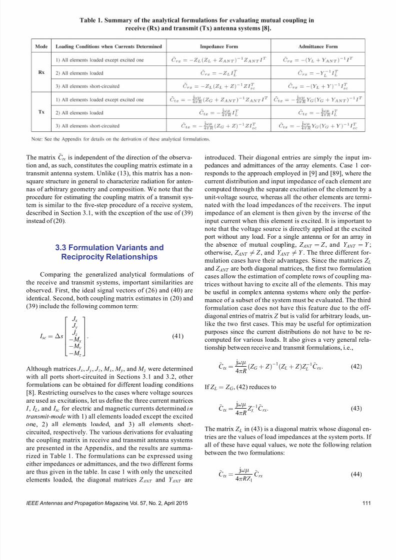
7232019 Unifying the Theory of Mutual Coupling Compensation in Antenna Arrays
httpslidepdfcomreaderfullunifying-the-theory-of-mutual-coupling-compensation-in-antenna-arrays 819
The matrix ~C tx is independent of the direction of the observa-
tion and as such constitutes the coupling matrix estimate in a
transmit antenna system Unlike (13) this matrix has a non-
square structure in general to characterize radiation for anten-
nas of arbitrary geometry and composition We note that the
procedure for estimating the coupling matrix of a transmit sys-tem is similar to the 1047297ve-step procedure of a receive system
described in Section 31 with the exception of the use of (39)
instead of (20)
33 Formulation Variants andReciprocity Relationships
Comparing the generalized analytical formulations of
the receive and transmit systems important similarities are
observed First the ideal signal vectors of (26) and (40) are
identical Second both coupling matrix estimates in (20) and
(39) include the following common term
I sc frac14 s
J x J y J z
M x M y M z
266664
377775 (41)
Although matrices J x J y J z M x M y and M z were determined
with all ports short-circuited in Sections 31 and 32 other
formulations can be obtained for different loading conditions
[8] Restricting ourselves to the cases where voltage sourcesare used as excitations let us de1047297ne the three current matrices
I I L and I sc for electric and magnetic currents determined in
transmit-mode with 1) all elements loaded except the excited
one 2) all elements loaded and 3) all elements short-
circuited respectively The various derivations for evaluating
the coupling matrix in receive and transmit antenna systems
are presented in the Appendix and the results are summa-
rized in Table 1 The formulations can be expressed using
either impedances or admittances and the two different forms
are thus given in the table In case 1 with only the unexcited
elements loaded the diagonal matrices Z ANT and Y ANT are
introduced Their diagonal entries are simply the input im-
pedances and admittances of the array elements Case 1 cor-
responds to the approach employed in [9] and [89] where the
current distribution and input impedance of each element are
computed through the separate excitation of the element by a
unit-voltage source whereas all the other elements are termi-nated with the load impedances of the receivers The input
impedance of an element is then given by the inverse of the
input current when this element is excited It is important to
note that the voltage source is directly applied at the excited
port without any load For a single antenna or for an array in
the absence of mutual coupling Z ANT frac14 Z and Y ANT frac14 Y
otherwise Z ANT 6frac14 Z and Y ANT 6frac14 Y The three different for-
mulation cases have their advantages Since the matrices Z Land Z ANT are both diagonal matrices the 1047297rst two formulation
cases allow the estimation of complete rows of coupling ma-
trices without having to excite all of the elements This may
be useful in complex antenna systems where only the perfor-mance of a subset of the system must be evaluated The third
formulation case does not have this feature due to the off-
diagonal entries of matrix Z but is valid for arbitrary loads un-
like the two 1047297rst cases This may be useful for optimization
purposes since the current distributions do not have to be re-
computed for various loads It also gives a very general rela-
tionship between receive and transmit formulations ie
~C tx frac14 j
4 RethZ G thorn Z THORN1ethZ L thorn Z THORNZ 1
L~C rx (42)
If Z L frac14 Z G (42) reduces to
~C tx frac14 j
4 RZ 1
L~C rx (43)
The matrix Z L in (43) is a diagonal matrix whose diagonal en-
tries are the values of load impedances at the system ports If
all of these have equal values we note the following relation
between the two formulations
~C tx frac14 j
4 RZ 1~C rx (44)
Table 1 Summary of the analytical formulations for evaluating mutual coupling in
receive (Rx) and transmit (Tx) antenna systems [8]
IEEE Antennas and Propagation Magazine Vol 57 No 2 April 2015 111
7232019 Unifying the Theory of Mutual Coupling Compensation in Antenna Arrays
httpslidepdfcomreaderfullunifying-the-theory-of-mutual-coupling-compensation-in-antenna-arrays 919
where Z 1 is the common load impedance value Since
j=4 RZ 1 is simply a complex scaling factor it is seen that
~C tx ~C rx (45)
This has important consequences because it implies that trans-
mit and receive formulations can be used interchangeably for
compensating mutual coupling when the load and generator
impedances are all equal In general only the relative ampli-
tudes and phases are required and therefore the scaling factor
has little importance in the compensation For systems wherethe load impedances are not equal a correction must be made
before interchanging the two formulations The latter is em-
bodied in the following equation
~C tx Z 1 L
~C rx (46)
This important relationship can be very useful in the compen-
sation of transmit arrays and in retrodirective systems The the-
ory presented here will be used in Section 5 in these two
applications
4 Efficiency of MutualCoupling Compensation
The analytical formulations in Table 1 generally give
matrices that have a number of rows equal to the number of
array elements and a number of columns governed by the
discretizations of closed surfaces Hence in general we are
dealing with nonsquare matrices that have signi1047297cantly more
columns than rows However it is possible to reduce the
number of columns through careful consideration of the sys-
tem physics [89]
The case of a system consisting entirely of a perfect electric conductor (PEC) is an interesting example Since the
closed surfaces of integration can be de1047297ned at the surfaces
of PEC the magnetic equivalent currents ~ M eq vanish by
boundary conditions and the sizes of the coupling matrix es-
timates ~C rx and ~C tx are reduced by half
The case of thin-wire elements such as monopoles or
dipoles is another interesting example If the wires are verti-
cally oriented and consist of a PEC horizontal electric cur-
rents J x and J y and all magnetic currents vanish leaving only
the electric currents J z in the evaluation of ~C rx and ~C tx Fur-
thermore if we are only interested in one elevation angle the current matrix can be rearranged to (47)
I frac14 s
P K 1
k frac141
J zk 1e j2 z k cos
P K 2
k frac14 K 1thorn1
J zk 1e j2 z k cos
P K N
k frac14 K N 1thorn1
J zk 1e j2 z k cos
P K 1
k frac141
J zkN e j2 z k cos
P K 2
k frac14 K 1thorn1
J zkN e j2 z k cos
P K N
k frac14 K N 1thorn1
J zkN e j2 z k cos
266666666664
377777777775
(47)
where J zkn is the entry of J z at its k th row and nth column z k
is the vertical location of the k th wire segment and K 1 to K N
are the last segment numbers for elements 1 to N The ideal
signal vector then takes the following form
videal frac14 E sin
e j2 sin eth x1 cos thorn y1 sin THORN
e j2
sin eth x2 cos thorn y2 sin THORN
e j2
sin eth x N cos thorn y N sin THORN
2664
3775 (48)
where xn and yn are the horizontal locations of the nth wire
Substituting (47) into the formulations in Table 1 gives
square matrices ~C rx and ~C tx Further to the signi1047297cant reduc-
tion in memory requirement for storing the coupling parame-
ters the matrix is invertible and can be used in (15) to
estimate incident signals in a receive system We note that
this size reduction is consistent with [50 ndash 57] and [59 ndash 78]
where a square structure is assumed for the coupling matrix
Unfortunately for other systems the number of cou-
pling parameters may become huge For this reason it is de-
sirable to study approaches that can reduce this number
while maintaining acceptable mutual coupling compensation
accuracy As discussed in [89] the calibration method in
[59 ndash 61] can be extended to handle antenna systems of arbi-
trary geometries This is done by judiciously appending rows
to the ideal signal vectors prior to mapping them to the mea-
sured vectors These additional rows must account for the re-
sponse to signals of various polarizations at locations
distributed over the whole structure of the antenna system
Acceptable accuracy can be obtained for electrical spacings
on this structure that are signi1047297cantly larger than those re-
quired for the computation of current distributions The ideal
signal vectors then take the same form as (26) and (40) but
with reduced dimensions Through careful consideration of the system physics it is possible to reduce the dimensions
even more in a similar fashion as previously described based
on the materials geometry and the absence of response to
some polarizations Steering vectors must be recorded for M
discrete directionspolarizations in the following matrix
V frac14 vrx1 vrx2
vrx M frac12 (49)
and the ideal signal vectors associated with these measured
vectors are recorded in
V ideal frac14 videal 1 videal 2 videal M frac12 (50)
The coupling matrix is then estimated through a least squares
approximation of ~C in V frac14 ~CV ideal using
~C frac14 VV ideal H V ideal V ideal
H 1
(51)
where ethTHORN H denotes the conjugate transpose operation The
condition for solution uniqueness is that the number of mea-
surements be at least equal to the number of rows of V ideal
This approach was demonstrated to be superior to any
IEEE Antennas and Propagation Magazine Vol 57 No 2 April 2015112
7232019 Unifying the Theory of Mutual Coupling Compensation in Antenna Arrays
httpslidepdfcomreaderfullunifying-the-theory-of-mutual-coupling-compensation-in-antenna-arrays 1019
existing interpolation technique in [90] for both simple and
complex geometries
The accuracy of ~C is highly dependent on the structure
of V ideal and the number of calibration points M speci1047297ed by
the engineer As discussed in [89 ndash 91] the condition number
of V ideal V ideal H can be closely monitored as an indication of
the best number of columns for ~C If the matrix ~C rx is avail-
able M can be arbitrarily increased and a hybrid approach
can be devised to bene1047297t from both a large number of steer-
ing vectors and a reduced number of coupling parametersThis hybrid approach estimates a smaller coupling matrix
than ~C rx through a least squares approximation of ~C in V frac14~C rxV ideal
0 frac14 ~CV ideal using
~C frac14 ~C rxV ideal 0V ideal
H V ideal V ideal H
1(52)
where V ideal 0 contains the ideal signal vectors whose dimen-
sions are consistent with ~C rx The reader is referred to [89]
for more details on this methodology
5 Applications
51 Retrodirective Systems
The reciprocity relationships derived in Section 3 can be
used to explain and extend the theory of retrodirective arrays
These arrays operate in such a way that incident signals are
retransmitted in the same directions that they are received
without sophisticated signal processing equipment in the
front-end Although various techniques are available for
achieving retrodirectivity the most popular is the Pon array
[92] which exploits the heterodyne technique where a fre-
quency mixer is connected at each of the array elements to perform phase conjugation of the received signals Using the
Schwarz inequality [93] and [94] proved that this phase con-
jugation gives optimal performance even in the presence of
strong mutual coupling The theory presented in Section 3
certainly supports this conclusion However to consider the
case of nonuniform loads the conventional circuit model of
Pon arrays can be extended to that in Figure 2 where the sig-
nals at the elements are scaled by the inverse of the conju-
gated load impedances
511 Polarization Diverse Systems
The theory in Section 3 can be veri1047297ed in a straightfor-
ward fashion using proven electromagnetic codes More spe-
ci1047297cally the numerical electromagnetic code (NEC) [95]
which is a method of moments solver is used here to model a
circular array consisting of four crossed dipole pairs shown
in Figure 3 Each of the pairs is comprised of two orthogonal
half-wave dipoles centrally terminated into individual load
impedances of 50 The array radius is equal to =4 Circu-
lar arrays are a popular choice due to their compactness and
the absence of ambiguities in azimuth The horizontal dipoles
add sensitivity to horizontally polarized signals Since the
horizontal and vertical dipoles are individually terminated
the system provides polarization agility and can handle sig-
nals of arbitrary polarizations This kind of array is therefore
very useful for verifying the theory presented in this paper
which has been generalized for arbitrary polarizations
Two approaches are available for verifying the theoryThe 1047297rst approach is more straightforward and involves the
excitation of the numerical model in receive-mode by an inci-
dent plane wave The complex conjugates of the received
voltages are then used as the values of voltage sources in
transmission and the resulting radiated electromagnetic 1047297elds
are computed If the theory is correct radiation should be
maximized in the direction of the incident plane wave
Figure 2 Compensated circuit model of a Pon retrodirec-
tive array consisting of four elements Received signals at
frequency f are passed through circulators and are mixed
with a local oscillator whose frequency is 2 f The signal
components at frequency f at the output of the mixers
are complex conjugates of the input signals These signalsare then ampli1047297ed before being returned to the antennas
through the circulators Ampli1047297cation is scaled by 1= Z Ln
to take into consideration nonuniform loading
Figure 3 Circular array of four crossed dipole pairs
IEEE Antennas and Propagation Magazine Vol 57 No 2 April 2015 113
7232019 Unifying the Theory of Mutual Coupling Compensation in Antenna Arrays
httpslidepdfcomreaderfullunifying-the-theory-of-mutual-coupling-compensation-in-antenna-arrays 1119
assuming an active implementation of the retrodirective sys-
tem where scattered 1047297elds can be ignored The second ap-
proach avoids a simulation in the receive-mode and computes
the coupling matrix of the system using the theory applicable
to receive systems in Section 3 This approach is favored
here since it will be reused in Section 52 Using the equa-
tions in Table 1 the current matrix required in the computa-
tion of the coupling matrix estimate takes the following form
I frac14
frac12 I z frac12 I xfrac12 I y
frac14
I11 I12 I18
I21 I22 I28
I31 I32 I38
I41 I42 I48
264 375I51 I52 I58
I61 I62 I68
I71 I72 I78
I81 I82 I88
26666666664
37777777775(53)
where is the segment length of the discretized dipoles and
the column vectors Iij contain the electric current distribu-
tions on dipole i due to the excitation of dipole j The dipoles
are modeled with thin wires hence currents are used in (53)
as opposed to current densities in (20) and the segment
length is used instead of the segment area s The wires
are assumed to be made of a PEC and all magnetic currents
are thus ignored This formulation assumes that the 1047297rst four
dipoles are vertical hence only z -directed currents are con-
sidered for these dipoles using submatrix frac12 I z The 1047297fth and
sixth dipoles are horizontal and oriented along the x-axis
hence only x-directed currents are considered for these two
dipoles using submatrix frac12 I x The seventh and eighth dipoles
are horizontal and oriented along the y-axis hence only y-
directed currents are considered for these two dipoles using sub-
matrix frac12 I y The ideal vector containing the incident signals takes
the following form
videal eth E E THORN
frac14
E sin
e j2
4
sin sinthornz1 coseth THORN
e j2
4
sin sinthornz2 coseth THORN
e j2
4
sin costhornz3 coseth THORN
e j2
4sin costhornz4 coseth THORN
26664
37775
eth E cos cos E sin THORN e j2 sin x5 costhorn
4sineth THORN
e j2 sin x6 cos
4sineth THORN
eth E cos sinthorn E cosTHORN e j2 sin
4costhorny7 sineth THORN
e j2
sin 4
costhorny8 sineth THORN
266666666666664
377777777777775
(54)
where the column vectors xn yn and zn contain the physical lo-
cations of the segments of the nth dipole It is implicitly as-
sumed in this formulation that the vertical and horizontal
dipoles are centered at eth x1 y1 z 1THORN frac14 eth x5 y5 z 5THORN frac14 eth0 =4 0THORN
eth x2 y2 z 2THORN frac14 eth x6 y6 z 6THORN frac14 eth0eth=4THORN 0THORN eth x3 y3 z 3THORN frac14 eth x7 y7 z 7THORN frac14eth=4 0 0THORN and eth x4 y4 z 4THORN frac14 eth x8 y8 z 8THORN frac14 etheth=4THORN 0 0THORN
respectively
The dipoles were discretized using 11 segments per di-
pole hence the coupling matrix estimate in reception ~C rx is
an 8 88 matrix The computation by NEC required ap-
proximately 65 kB of storage and 01 s of runtime to obtain
each column of (53) The received voltages can be estimated
for an arbitrary illumination using
vrxeth E E THORN frac14 ~C rxvideal eth E E THORN (55)
which requires 704 complex operations Since the array is
uniformly loaded the complex conjugate of (55) can be used
directly as the excitation of a transmit system of identical ge-
ometry and whose generator impedances are equal to the50- loads according to the following equation
vtx frac14 vrxeth E E THORN(56)
where ethTHORNdenotes the complex conjugate operation To con-
1047297rm that this is correct (55) is used to estimate the received
voltages for a vertically polarized signal arriving from azi-
muth angles frac14 0 30 60 and 90 for elevation angles
frac14 90 and 45 This is done by computing videal eth0 901 0THORN v ideal eth30 90 1 0THORN videal eth60 90 1 0THORN videal eth90 901 0THORN videal eth0 45 1 0THORN videal eth30 45 1 0THORN videal eth60 451 0THORN and videal eth90 45 1 0THORN using (54) and substituting this
into (55) These results are then substituted into (56) and used directly in a numerical simulation in transmission Volt-
age sources having the values contained in vtx are applied at
the element ports while including generator impedances
Z G frac14 50 and the -component of the radiated electric 1047297elds
are calculated using NEC Note that the horizontal dipoles do
not contribute to radiation for frac14 90 due to the vertical po-
larization of the incident signal but they do for frac14 45 be-
cause a horizontal incident 1047297eld exists for vertically polarized
signals arriving from 6frac14 90 The results are shown in
Figure 4 For comparison the results of a Van Atta imple-
mentation are also presented [96] In this case phase conju-
gation is attempted using vtx frac14 frac12vrx2 vrx1 vrx4 vrx3 vrx6 vrx5 vrx8 vrx7 T
It is seen in Figure 4 that the use of (56) gives very satisfying
performance in all the plotted scenarios since the transmitted
power is maximized in the directions of the incident signals
By comparing the radiation patterns for frac14 0 and frac14 90
it is veri1047297ed that the radiation patterns repeat in each quadrant
due to the symmetry of the system As discussed in [97] and
[98] the performance of the Van Atta implementation is seen
to be suboptimal due to mutual coupling effects with reduced
power levels in the directions of incident signals
512 Nonuniformly Loaded Systems
To evaluate the impact of ignoring nonuniform loading
the linear array shown in Figure 5 is now considered This ar-
ray consists of dipoles having lengths decreasing from 06to 03 as we move along the x-axis and whose loads are the
complex conjugate of their self-impedances The coupling
matrix can be estimated using the current matrix given by
I frac14 I z frac14
I11 I12 I17
I21 I22 I27
I71 I72 I77
264
375 (57)
IEEE Antennas and Propagation Magazine Vol 57 No 2 April 2015114
7232019 Unifying the Theory of Mutual Coupling Compensation in Antenna Arrays
httpslidepdfcomreaderfullunifying-the-theory-of-mutual-coupling-compensation-in-antenna-arrays 1219
The currents in (57) were computed using NEC which re-
quired approximately 54 kB of storage and less than 01 s of
runtime to obtain each column of matrix I with each of the el-
ements discretized into 11 segments Noting that the array el-
ements only respond to vertically polarized signals the parameters E and E can be ignored and the ideal signal
vector is given by
videal eth THORN frac14 sin
e j2 eth03 sin costhornz1 cos THORN
e j2
eth06 sin costhornz2 cos THORN
e j2
eth21 sin costhornz7 cos THORN
2664
3775 (58)
For a similar system used in transmission and having genera-
tor impedances given by Z G frac14 Z L the values of the voltage
sources are determined using
vtx frac14 Z L1vrxeth THORN
frac14 Z L
1~C rxvideal eth THORN
(59)
The -component of the radiated electric 1047297eld of the trans-
mit system is plotted in Figure 6 for an incident signal arriv-
ing from azimuth angles frac14 0 60 120 and 180 for
elevation angles frac14 90 and 45 For comparison the re-
sults are also shown when the nonuniform loading is ig-
nored This is equivalent to simply assuming that Z L is
proportional to the identity matrix in (59) It is observed
here that the consideration of nonuniform loading is critical
in the implementation of retrodirective systems otherwise
suboptimal performance is possible All the retrodirective
patterns obtained with proper consideration of nonuniform
loading are veri1047297ed to be satisfactory with their main beams
pointing in the directions of the incident signal These re-
sults strongly support the theory in Section 3 and the circuit
model in Figure 2
Figure 5 Nonuniform linear array of seven nonuniformly
loaded vertical dipoles Each dipole has a different length
and is terminated with a load impedance equal to the
complex conjugate of its self-impedance
Figure 6 Retrodirective radiation patterns of the nonuni-
form linear array of seven vertical dipoles in Figure 5 il-
luminated by a vertically polarized signal arriving from
frac14 0 frac14 60 frac14 120 and frac14 180 respectively (top
to bottom plots) The radiation patterns on the left are
for an elevation angle of 90 and those on the right are
for an elevation angle of 45 It is seen that the nonuni-
form loads must be carefully considered to obtain opti-
mized radiation with a main beam directed toward the
incident signal
Figure 4 Retrodirective radiation patterns of the circular
array of four crossed dipole pairs in Figure 3 illuminated
by a vertically polarized signal arriving from frac14 0
frac14 30 frac14 60 and frac14 90 respectively (top to bottom
plots) The radiation patterns on the left are for an eleva-
tion angle of 90 and those on the right are for an eleva-
tion angle of 45 The Pon implementation is seen to give
better results than the Van Atta due to mutual coupling
effects with optimized radiation and a main beam in the
direction of the incident signal
IEEE Antennas and Propagation Magazine Vol 57 No 2 April 2015 115
7232019 Unifying the Theory of Mutual Coupling Compensation in Antenna Arrays
httpslidepdfcomreaderfullunifying-the-theory-of-mutual-coupling-compensation-in-antenna-arrays 1319
52 ReceiveTransmit Beamforming
Beamforming is a popular application in receive an-
tenna systems for maximizing the reception of a desired sig-
nal while minimizing interference To perform beamforming
in transmission the directions and polarizations of distant re-
ceive systems must be known The reciprocity relationships
in Section 3 give us the con1047297dence to use received quantities
for transmission This is studied in this section where trans-
mit systems are calibrated using coupling matrices and sig-
nals processed in reception
521 Polarization Diverse Systems
The circular array of four crossed dipole pairs illus-
trated in Figure 3 is 1047297rst considered In accordance with the
theory in Section 3 since all the elements are terminated in
equal loads the receive coupling matrix estimate ~C rx de-
rived in Section 51 can also be used here to compensate
mutual coupling in transmission Unlike the retrodirective
system in Section 51 where coupling matrices were only
employed for analysis purposes the reduction of the matrix
size is desirable in a transmit beamformer to minimize the
memory requirement and computations in a practical imple-
mentation Using the hybrid approach introduced in
Section 4 the size of the matrix is further reduced to 8 40 for a total of 320 stored complex coupling parameters in-
stead of 704 This is done by subdividing each of the eight
dipoles into 1047297ve larger segments instead of the 11 used in
the numerical evaluation of ~C rx The column vectors xn yn
and zn in the ideal signal vector of (54) therefore consist of
1047297ve entries
Using the 8 40 matrix ~C obtained by (52) a correla-tion matrix assuming six uncorrelated signals is generated
using
R xx frac14 ~C X6
ifrac141
videal i i E i E i
videal i i E i E i
H
~C
H thorn 2o I N (60)
where ethTHORN H is the conjugate transpose operation i i E i
and E i are the arrival and polarization parameters describing
the ith signal I N is the identity matrix whose dimensions areequal to the number of array elements N frac14 8 and 2o frac14000001 is a 1047297ctitious noise power used for loading the diago-
nal of R xx to ensure a reasonable condition number The noise
is hereby modeled as uncorrelated zero-mean additive white
Gaussian This example considers a scenario involving six
signals at an elevation of frac14 45 Two of these are right-
hand circularly polarized (RHCP) signals arriving from frac140 and 60 two are left-hand circularly polarized (LHCP) sig-
nals arriving from frac14 30 and 30 one is a horizontally
polarized signal arriving from frac14 90 and one is a verti-
cally polarized signal arriving from frac14 120 Radiation is
optimized in the direction of the vertically polarized signal at
frac14 120 and all other signals are considered as interferers
The voltage sources of this system in transmission are then
determined using
vtx frac14 R xx1~C videal eth120 45 1 0THORN
(61)
Using these voltage sources in the numerical model in trans-
mission the radiated electric 1047297eld components E eth THORN and
E eth THORN are computed with NEC The radiation patterns in
transmission at an elevation of frac14 45 for the four different
polarizations of the signals are plotted in Figure 7 These pat-
terns are obtained through the following combinations of the
two orthogonal 1047297eld components
E veth THORN frac14 E eth THORN
E heth THORN frac14 E eth THORN
E RHCP eth THORN frac14 jE eth THORN thorn E eth THORN
E LHCP eth THORN frac14 E eth THORN thorn jE eth THORN (62)
where the subscripts v h RHCP and LHCP stand for verti-
cal horizontal right-hand circular and left-hand circular
polarizations respectively
The results in Figure 7 are very satisfying since nulls
are formed in transmission not only in the directions of the
1047297ve interferers but also with the correct polarizations and
thus con1047297rm that coupling matrices are effective in mutual
coupling compensation of both receive and transmit
Figure 7 Radiation patterns in transmission of the circular
array of four crossed dipole pairs in Figure 3 for receivers
of various polarizations at an elevation of 45 using an 8 40 coupling matrix estimate Radiation is maximized for a
vertically polarized receiver at 120 and minimized for a
horizontally polarized receiver at 90 LHCP receivers at
30 and 30 and RHCP receivers at 0 and 60 Mutual
coupling is compensated effectively with a main beam and
deep nulls forming in these directions
IEEE Antennas and Propagation Magazine Vol 57 No 2 April 2015116
7232019 Unifying the Theory of Mutual Coupling Compensation in Antenna Arrays
httpslidepdfcomreaderfullunifying-the-theory-of-mutual-coupling-compensation-in-antenna-arrays 1419
beamforming systems By reciprocity it is expected that an-
tennas both transmit and receive with the same polarizations
These results suggest that a wireless network can be opti-
mized when signals are transmitted and received using the
same antennas and proper mutual coupling compensation is
implemented Note that if the desired signal waveform is
known and all signals are being transmitted by distant sys-
tems vtx in (61) can also be determined through adaptive
techniques without knowledge of ~C and the desired signalrsquosdirection and polarization The theory presented in this paper
con1047297rms that both deterministic and adaptive approaches can
be effective in the optimization of wireless networks
522 Nonuniformly Loaded Systems
The nonuniform linear array of seven dipoles shown in
Figure 5 is now considered to study the impact of nonuni-
form loading in beamforming The coupling matrix of this
system in reception ~C rx derived in Section 51 is reduced
using the hybrid approach in Section 4 to a 7 35 ~C matrixfor a total of 245 stored complex coupling parameters in-
stead of 539 Although the dipoles are of different lengths a
reduced discretization scheme involving 1047297ve segments per
dipole is nonetheless used in this example The column
vector zn in the ideal signal vector of (58) therefore contains
1047297ve entries instead of the 11 entries used with the original
matrix
Using the 7 35 matrix ~C obtained by (52) and the
same six-signal scenario as in Section 521 the correlation
matrix estimated in reception ie R xx can be used to
determine the required voltage sources in transmission How-
ever nonuniform loading must be accounted for as follows
vtx frac14 Z L1 R xx Z L
H 1
h i1
Z L1~C videal eth120 45THORN
frac14 Z L H R xx
1~C videal eth120 45THORN
(63)
where the parameters E and E are ignored due to the pure
vertical polarization of the antenna system The resulting ra-
diation patterns in transmission are presented in Figure 8along with those obtained when nonuniform loading is
ignored It is seen that optimum beamforming is achieved
since the main beam is in the direction of the desired signal
while deep nulls form in the directions of the interferers As
already observed in Section 51 the main beam of the radia-
tion pattern is adversely affected when nonuniform loading is
ignored in a system where load impedances signi1047297cantly
vary It is seen that interference nulling would also signi1047297-
cantly suffer by the improper compensation of this transmit
system with attenuation of no more than 12 dB in the direc-
tions of the interferers
53 DOAPolarization Estimation
In some applications it is necessary to estimate the
DOA and polarization of incident signals Accurate mutual
coupling compensation is critical in such applications since it
directly affects the accuracy and resolution of the estimator
The eight-dipole array in front of a rectangular conducting
plate similar to that in [80] is considered here This antenna
system is illustrated in Figure 9 For 2-D operation the cou-
pling matrix is estimated as indicated in the 1047297gure The left
part of the matrix is associated with the dipoles and uses row
vectors cij whereas the rectangular conducting plate is subdi-
vided along the horizontal and vertical axes to account for
the variable horizontal and vertical phase shifts of incident
Figure 8 Radiation patterns in transmission of the non-
uniform linear array of seven vertical dipoles in Figure 5
for receivers at an elevation of 45 using a 7 35 cou-
pling matrix estimate Radiation needs to be maximized
at 120 and minimized at 60 30 0 30 and 60
It is seen that the nonuniform loads must be carefullyconsidered to obtain optimized radiation with properly
directed main beam and deep nulls
Figure 9 Geometry of the eight-dipole array in front of a
conducting plate for 2-D operation Eight row vectors as-
sociated with the dipoles 1047297ll the left part of the coupling
matrix for each of its rows whereas the other columns
are associated with the different portions of the plate
IEEE Antennas and Propagation Magazine Vol 57 No 2 April 2015 117
7232019 Unifying the Theory of Mutual Coupling Compensation in Antenna Arrays
httpslidepdfcomreaderfullunifying-the-theory-of-mutual-coupling-compensation-in-antenna-arrays 1519
signals Due to the 1047297nite dimensions of the conducting plate
the polarizations of the array elements may have horizontal
components and both horizontally and vertically oriented in-
cident 1047297elds have to be accounted for on the plate using the
complex scalar parameters C yij and C z
ij respectively
This antenna system is modeled with FEKO [99] using
the method of moments The dipoles are modeled by thin
wires having a length of 612 cm spaced 49 cm apart and
centrally terminated into 50- load impedances The rectan-
gular plate is modeled by a thin 3916-cm-wide and 24-cm-high perfectly conducting surface located 3 cm behind the
dipoles The numerical calculations are performed for an op-
erating frequency of 245 GHz Reordering the entries of the
right part of the matrix for mathematical conciseness the
coupling matrix estimate is obtained by the equations in
Table 1 with the current matrix having the following form
I frac14
z frac12 I wires
s J z J y
24 35frac14
z
I11 I18
I81 I88
24
35
s
J z 91 J z 98
J zK 1 J zK 8
J y91 J y98
J yK 1 J yK 8
2666666437777775
26666666666664
37777777777775
(64)
where z and s are the dipole segment length and conduct-
ing plate patch area respectively I ij is a column vector con-
taining the electric currents on the segments of element i due
to the excitation of element j and J yij and J zij are the y- and
z -directed electric current densities on patch i of the conduct-
ing plate due to the excitation of element j The ideal signal
vector of this problem takes the following form
videal eth E E THORN
frac14
E sin
e j 2 sin ethx1 cos thorny1 sin THORNthornz1 cos frac12
e j 2
sin ethx8 cos thorny8 sin THORNthornz8 cos frac12
e j 2 eth y9 sin sin thorn z 9 cos THORN
e j 2
eth y K sin sin thorn z K cos THORN
266666664
377777775
eth E cos sin thorn E cos THORN
e j2
eth y9 sin sin thorn z 9 cos THORN
e j2
eth y K sin sin thorn z K cos THORN
2
64
3
75
26666666666666664
37777777777777775
(65)
where x j y j and z j are column vectors containing the x y
and z physical locations of the wire segments for j 8 and
y j and z j are scalar values of the y and z locations of the con-
ducting plate patches for j 9 Note that this formulation
assumes that the conducting plate is located at x frac14 0 The nu-
merical solution of this problem involved a total of 104 wire
segments and 2923 surface patches which required approxi-
mately 150 MB of storage and 51 s of runtime to obtain each
of the columns of (64) Since two columns are required to
account for both y- and z -directed currents on each patch the
coupling matrix estimate turns out to be an 8 5950 matrix
Using the size-reduction guidelines presented in Section 4
the size of the estimate can be reduced at the expense of
some performance degradation Here the method is imple-
mented by subdividing the wires into 1047297ve segments each for
a total of 40 wire segments instead of 104 and the conduct-
ing plate into 70 patches 10 wide by 7 high instead of
2923 The size of the coupling matrix estimate then reduces
to 8 180 for a total of 1440 stored complex coupling pa-
rameters instead of 47 600 This is done by computing thesteering vectors for both vertically and horizontally polarized
signals arriving from 85 85 and 25 1725
with angular increments of 10 These two sets of steering
vectors are obtained by substituting videal eth 1 0THORN and
videal eth 0 1THORN as the columns of the matrix V ideal 0 in (52) for
324 different combinations of and Since two polariza-
tions are considered the total number of calibration points is
648 The matrix V ideal in (52) is then a 180 648 matrix con-
taining the ideal signal vectors for the reduced discretization
scheme and the 648 calibration points
The popular MUltiple SIgnal Classi1047297cation (MUSIC)algorithm described in [100 ndash 102] is employed here to per-
form DOA estimation in a polarization diverse scenario By
the theory of this paper the MUSIC DOA spectrum can be
expressed as
P eth THORN frac14 1
min eth A H ATHORN1 A H E N E N
H Ah i (66)
where
A frac14 ~C videal eth 1 0THORN videal eth 0 1THORNfrac12 (67)
minfrac12 is the smallest eigenvalue of the matrix inside the
brackets and E N is the matrix containing the noise eigen-
vectors obtained through the eigendecomposition of the cor-
relation matrix A signal scenario involving two plane waves
arriving from eth THORNfrac14eth30 60THORN and eth THORN frac14 eth0 45THORN re-
spectively is considered In addition the two signals are
circularly polarized The 1047297rst signal is RHCP ie eth E E THORN frac14eth j 1THORN whereas the second signal is LHCP ie eth E E THORN frac14eth1 j THORN The eigenvalue decomposition of the correlation matrix
provides six noise eigenvectors which are associated with
the six smallest eigenvalues to 1047297ll the matrix E N in (66) The
2-D DOA spectra are presented in Figure 10
For comparison the DOA spectra obtained without
compensation with a square coupling matrix having dimen-
sions 8 8 and with the full 8 5950 matrix are also
shown The accuracies and resolutions obtained with the
larger matrices in Figure 10c and d are seen to be signi1047297-
cantly better The reduced 8 180 matrix is seen to be a
very reasonable compromise with a slight performance degra-
dation but a reduction of approximately 97 of the memory
requirement and computations required for the evaluation of
the DOA spectra
IEEE Antennas and Propagation Magazine Vol 57 No 2 April 2015118
7232019 Unifying the Theory of Mutual Coupling Compensation in Antenna Arrays
httpslidepdfcomreaderfullunifying-the-theory-of-mutual-coupling-compensation-in-antenna-arrays 1619
It is important to note here that the 8 180 ~C matrixcan also be determined with measurements using (51) where
the matrix V is 1047297lled with measured steering vectors In the
case studied in this section 648 measured steering vectors
are necessary to obtain ~C This is a substantial reduction
compared with the number of measurements required for 2-D
operation using conventional means More details on this are
available in [89]
6 Conclusion
This paper has thoroughly reviewed the limitations of current mutual coupling compensation methods Through the
derivation of clear theoretical foundations that apply to both
receive and transmit systems the theory of mutual coupling
compensation was uni1047297ed to provide ef 1047297cient mutual coupling
compensation methods that can be employed with systems of
arbitrary geometries Reciprocity relationships were clearly
derived based on the receive and transmit formulations
thereby allowing the use of receive-mode compensation data
for both reception and transmission if the reciprocity relation-
ships are employed properly Both theoretical and experimen-
tal techniques can be used to evaluate mutual coupling by the
presented theory This theory can be veri1047297ed in a straight-forward fashion using proven electromagnetic codes and the
examples given in this paper on retrodirective systems beam-
formers and DOA estimation can be followed by the reader
for validation Finally this theory will likely 1047297nd several other
applications than those presented and contributes to the areas
of antenna theory mutual coupling analysis complex struc-
ture modeling and antenna measurements
7 AppendixDerivation of Analytical
Formulations in Table 1
The analytical formulations presented in Table 1 are
better understood using the various equivalent circuits of an-
tenna systems shown in Figure 11 In receive-mode the
open-circuit voltages are given by
voc A frac14 Z ANT I T videal (68)
voc L frac14 ethZ L thorn Z THORN I T
L videal (69)
voc frac14 ZI T scvideal (70)
Figure 10 2-D DOA estimation using the eight-dipole linear array in front of a rectangular con-
ducting plate for two circularly polarized signals from eth THORN frac14 eth30 60THORN and eth0 45THORN using
MUSIC Mutual coupling compensation implemented with an 8 180 coupling matrix estimate is
seen to give very satisfying performance and ef 1047297ciency with sharp peaks toward the two signals
IEEE Antennas and Propagation Magazine Vol 57 No 2 April 2015 119
7232019 Unifying the Theory of Mutual Coupling Compensation in Antenna Arrays
httpslidepdfcomreaderfullunifying-the-theory-of-mutual-coupling-compensation-in-antenna-arrays 1719
This is consistent with classic antenna theory presented in
[6] The port voltages should be equal irrespective of the
method By circuit theory these are given by
vrx frac14 Z LethZ L thorn Z ANT THORN1
voc A (71)
frac14 Z LethZ L thorn Z THORN1voc L
(72)
frac14 Z LethZ L thorn Z THORN1voc (73)
Substituting (68) ndash (70) into (71) ndash (73) and performing some
matrix manipulations gives
vrx frac14 Z LethZ L thorn Z ANT THORN1
Z ANT I T videal (74)
frac14 Z L I T L videal (75)
frac14 Z LethZ L thorn Z THORN1ZI T
scvideal (76)
The admittance formulations are obtained by substituting
Z L frac14 Y L1 Z ANT frac14 Y ANT
1 and Z frac14 Y 1 into (74) ndash (76) For
example (76) gives
vrx frac14 Y 1 L Y 1
L thorn Y 1 1
Y 1 I T scvideal
frac14 Y 1 L Y LethY L thorn Y THORN1
YY 1 I T scvideal
frac14 ethY L thorn Y THORN1 I T
scvideal (77)
In transmit-mode the radiated 1047297elds are scaled by v A v L
and v which are obtained by voltage division in 1) and 3)
In 2) v L is simply equal to vtx The admittance formulations
in transmit-mode are obtained in the same fashion as the ex-
ample of (77)
8 References
[1] H S Lui H T Hui and M S Leong ldquoA note on the mutualcoupling problems in transmitting and receiving antenna arraysrdquo IEEE Antennas Propag Mag vol 51 no 5 pp 171 ndash 176 Oct 2009
[2] C A Balanis Antenna Theory Analysis and Design 2nd ed NewYork NY USA Wiley 1997
[3] R C Hansen Phased Array Antennas New York NY USA Wiley1998
[4] T A Milligan Modern Antenna Design 2nd ed New York NYUSA Wiley 2005
[5] R J Mailloux Phased Array Antenna Handbook 2nd ed BostonMA USA Artech House 2005[6] S A Schelkunoff and H T Friis Antennas Theory and Practice
New York NY USA Wiley 1952[7] R P Meys ldquoA summary of the transmitting and receiving properties
of antennasrdquo IEEE Antennas Propag Mag vol 42 no 3 pp 49 ndash 53Jun 2000
[8] S Henault ldquoEvaluation of electromagnetic coupling in antenna sys-tems A uni1047297ed theory and its applicationsrdquo PhD dissertation DeptElect Comput Eng Royal Military College of Canada KingstonON Canada Jan 2012
[9] S Henault Y M M Antar S Rajan R Inkol and S Wang ldquoThemultiple antenna induced EMF method for the precise calculation of thecoupling matrix in a receiving antenna arrayrdquo Progr Electromagn Res M vol 8 pp 103 ndash 118 2009
[10] P S Carter ldquoCircuit relations in radiating systems and applications toantenna problemsrdquo Proc IRE vol 20 no 6 pp 1004 ndash 1041 Jun 1932
[11] H E King ldquoMutual impedance of unequal length antennas in echelonrdquo IRE Trans Antennas Propag vol AP-5 no 3 pp 306 ndash 313 Jul 1957
[12] J H Richmond and N H Geary ldquoMutual impedance of nonplanar-skew sinusoidal dipolesrdquo IEEE Trans Antennas Propag vol AP-23no 3 pp 412 ndash 414 May 1975
[13] J D Kraus Antennas 2nd ed New York NY USA McGraw-Hill1988
[14] S A Mitilineos C A Papagianni G I Verikaki and C N CapsalisldquoDesign of switched beam planar arrays using the method of geneticalgorithmsrdquo Progr Electromagn Res vol 46 pp 105 ndash 126 2004
[15] A W Love ldquoComment On the equivalent circuit of a receiving antennardquo IEEE Antennas Propag Mag vol 44 no 5 pp 124 ndash 125 Oct 2002
[16] J B Andersen and R G Vaughan ldquoTransmitting receiving and scat-tering properties of antennasrdquo IEEE Antennas Propag Mag vol 45no 4 pp 93 ndash 98 Aug 2003
[17] J Van Bladel ldquoOn the equivalent circuit of a receiving antennardquo
IEEE Antennas Propag Mag vol 44 no 1 pp 164 ndash
165 Feb 2002[18] R E Collin ldquoLimitations on the Thevenin and Norton equivalent cir-cuits for a receiving antennardquo IEEE Antennas Propag Mag vol 45no 2 pp 119 ndash 124 Apr 2003
[19] C T Tai ldquoA Critical study of the circuit relations of two distant an-tennasrdquo IEEE Antennas Propag Mag vol 44 no 6 pp 32 ndash 37Dec 2002
[20] C T Tai ldquoCorrection V A critical study of the circuit relations of twodistant antennasrdquo IEEE Antennas Propag Mag vol 45 no 1 p 125Feb 2003
[21] A W Love ldquoCorrection V A critical study of the circuit relations of twodistant antennasrdquo IEEE Antennas Propag Mag vol 45 no 2 p 42Apr 2003
[22] C G Montgomery R H Dicke and E M Purcell Principles of Microwave Circuits New York NY USA McGraw-Hill 1948
[23] S Ramo and J Whinnery Fields and Waves in Modern Radio 2nd ed New York NY USA Wiley 1953
[24] S Silver Microwave Antenna Theory and Design New York NYUSA McGraw-Hill 1949
[25] R C Hansen ldquoRelationships between antennas as scatterers and asradiatorsrdquo Proc IEEE vol 77 no 5 pp 659 ndash 662 May 1989
[26] C C Su ldquoOn the equivalent generator voltage and generator internalimpedance for receiving antennasrdquo IEEE Trans Antennas Propagvol 51 no 2 pp 279 ndash 285 Feb 2003
[27] S R Best and B C Kaanta ldquoA tutorial on the receiving and scattering properties of antennasrdquo IEEE Antennas Propag Mag vol 51 no 5 pp 26 ndash 37 Oct 2009
[28] J W Wallace and R Mehmood ldquoOn the accuracy of equivalent circuit models for multi-antenna systemsrdquo IEEE Trans Antennas Propagvol 60 no 2 pp 540 ndash 547 Feb 2012
[29] D M Pozar ldquoThe active element patternrdquo IEEE Trans Antennas Pro- pag vol 42 no 8 pp 1176 ndash 1178 Aug 1994
Figure 11 Equivalent circuits of (left) transmit and (right)
receive antenna systems for the three different loading con-
ditions given in Table 1 These equivalent circuits use vec-
tors and matrices to represent voltages and impedances
IEEE Antennas and Propagation Magazine Vol 57 No 2 April 2015120
7232019 Unifying the Theory of Mutual Coupling Compensation in Antenna Arrays
httpslidepdfcomreaderfullunifying-the-theory-of-mutual-coupling-compensation-in-antenna-arrays 1819
[30] D F Kelley and W L Stutzman ldquoArray antenna pattern modelingmethods that include mutual coupling effectsrdquo IEEE Trans Antennas Propag vol 41 no 12 pp 1625 ndash 1632 Dec 1993
[31] K Takamizawa ldquoAnalysis of highly coupled wideband antenna arraysusing scattering parameter network modelsrdquo PhD dissertation DeptElect Comput Eng Virginia Polytech Inst State Univ BlacksburgVA USA Dec 2002
[32] D M Pozar ldquoA relation between the active input impedance and theactive element pattern of a phased arrayrdquo IEEE Trans Antennas Propag vol 51 no 9 pp 2486 ndash 2489 Sep 2003
[33] D F Kelley ldquoRelationships between active element patterns and mutual impedance matrices in phased array antennasrdquo in Proc IEEE Int Symp Antennas Propag 2002 pp 524 ndash 527
[34] D F Kelley ldquo
Embedded element patterns and mutual impedancematrices in the terminated phased array environmentrdquo in Proc IEEE Int Symp Antennas Propag 2005 pp 659 ndash 662
[35] R F Harrington ldquoAntenna excitation for maximum gainrdquo IEEE Trans Antennas Propag vol AP-13 no 6 pp 896 ndash 903 Nov 1965
[36] H Rogier and E Bonek ldquoAnalytical spherical-mode-based compensa-tion of mutual coupling in uniform circular arrays for direction-of-arrivalestimationrdquo Int J Electron Commun vol 60 no 3 pp 179 ndash 189Mar 2006
[37] A T De Hoop ldquoThe N-port receiving antenna and its equivalent elec-trical networkrdquo Philips Res Rep vol 30 pp 302 ndash 315 1975
[38] P S Kildal ldquoEquivalent circuits of receive antennas in signal process-ing arraysrdquo Microw Opt Technol Lett vol 21 no 4 pp 244 ndash 246May 1999
[39] K F Warnick B Woestenburg L Belostotski and P Russer ldquoMinimiz-ing the noise penalty due to mutual coupling for a receiving arrayrdquo IEEE Trans Antennas Propag vol 57 no 6 pp 1634 ndash 1644 Jun 2009
[40] R O Schmidt ldquoMultilinear array manifold interpolationrdquo IEEE TransSignal Process vol 40 no 4 pp 857 ndash 866 Apr 1992
[41] A J Weiss and B Friedlander ldquoManifold interpolation for diversely po-larized arraysrdquo Proc Inst Elect Eng V Radar Sonar Navig vol 141no 1 pp 19 ndash 24 Feb 1994
[42] R J Allard and D H Werner ldquoThe model-based parameter estimationof antenna radiation patterns using windowed interpolation and sphericalharmonicsrdquo IEEE Trans Antennas Propag vol 51 no 8 pp 1891 ndash 1906 Aug 2003
[43] M Landmann and G Del Galdo ldquoEf 1047297cient antenna description for MIMO channel modelling and estimationrdquo in Proc 7th Eur ConfWireless Technol Amsterdam The Netherlands 2004 pp 217 ndash 220
[44] G Del Galdo J Lotze M Landmann and M Haardt ldquoModelling and manipulation of polarimetric antenna beam patterns via sphericalharmonicsrdquo in Proc 14th Eur Signal Process Conf Florence ItalySep 2006 pp 1 ndash 5
[45] F Belloni A Richter and V Koivunen ldquo
DoA estimation via manifold separation for arbitrary array structuresrdquo IEEE Trans Signal Processvol 55 no 10 pp 4800 ndash 4810 Oct 2007
[46] H T Hui ldquoDecoupling methods for the mutual coupling effect in an-tenna arrays A reviewrdquo Recent Patents Eng vol 1 no 2 pp 187 ndash 193 Jun 2007
[47] T Su and H Ling ldquoOn modeling mutual coupling in antenna arraysusing the coupling matrixrdquo Microw Opt Technol Lett vol 28 no 4 pp 231 ndash 237 Feb 2001
[48] P Darwood P N Fletcher and G S Hilton ldquoMutual couplingcompensation in small planar array antennasrdquo Proc Inst Elect Eng V
Microw Antennas Propag vol 145 no 1 pp 1 ndash 6 Feb 1998[49] H Steyskal and J S Herd ldquoMutual coupling compensation in small array
antennasrdquo IEEE Trans Antennas Propag vol 38 no 12 pp 1971 ndash 1975 Dec 1990
[50] I J Gupta and A A Ksienski ldquoEffect of mutual coupling on the performance of adaptive arraysrdquo IEEE Trans Antennas Propag
vol AP-31 no 5 pp 785 ndash 791 Sep 1983[51] C C Yeh M L Leou and D R Ucci ldquoBearing estimations with mu-
tual coupling presentrdquo IEEE Trans Antennas Propag vol 37 no 10 pp 1332 ndash 1335 Oct 1989
[52] C Roller and W Wasylkiwskyj ldquoEffects of mutual coupling on super-resolution DF in linear arraysrdquo in Proc IEEE Int Conf AcoustSpeech Signal Process vol 5 1992 pp 257 ndash 260
[53] Z Huang C A Balanis and C R Birtcher ldquoMutual couplingcompensation in UCAs Simulations and experimentrdquo IEEE Trans Antennas Propag vol 54 no 11 pp 3082 ndash 3086 Nov 2006
[54] K C Lee and T H Chu ldquoA circuit model for mutual couplinganalysis of a 1047297nite antenna arrayrdquo IEEE Trans Electromagn Compatvol 38 no 3 pp 483 ndash 489 Aug 1996
[55] K W Lo and T B Vu ldquoSimple S-parameter model for receiving an-tenna arrayrdquo Electron Lett vol 24 no 20 pp 1264 ndash 1266 Sep 1988
[56] K M Pasala and E M Friel ldquoMutual coupling effects and their reduction in wideband direction of arrival estimationrdquo IEEE Trans Aerosp Electron Syst vol 30 no 4 pp 1116 ndash 1122 Apr 1994
[57] R S Adve and T K Sarkar ldquoCompensation for the effects of mutualcoupling on direct data domain adaptive algorithmsrdquo IEEE Trans An-tennas Propag vol 48 no 1 pp 86 ndash 94 Jan 2000
[58] R F Harrington Field Computation by Moment Methods New York NY USA Wiley 1968
[59] J Pierre and M Kaveh ldquoExperimental performance of calibration and direction-1047297nding algorithmsrdquo in Proc IEEE Int Conf Acoust SpeechSignal Process vol 2 Toronto ON Canada Apr 1991 pp 1365 ndash 1368
[60] T Su K Dandekar and H Ling ldquoSimulation of mutual couplingeffect in circular arrays for direction-1047297nding applicationsrdquo Microw
Opt Technol Lett vol 26 no 5 pp 331 ndash
336 Sep 2000[61] K R Dandekar H Ling and G Xu ldquoExperimental study of mutualcoupling compensation in smart antenna applicationsrdquo IEEE TransWireless Commun vol 1 no 3 pp 480 ndash 487 Jul 2002
[62] H T Hui ldquoReducing the mutual coupling effect in adaptive nullingusing a re-de1047297ned mutual impedancerdquo IEEE Microw Wireless Compon Lett vol 12 no 5 pp 178 ndash 180 May 2002
[63] H T Hui ldquoCompensating for the mutual coupling effect in direction1047297nding based on a new calculation method for mutual impedancerdquo IEEE Antennas Wireless Propag Lett vol 2 no 1 pp 26 ndash 29 2003
[64] H T Hui ldquoImproved compensation for the mutual coupling effect ina dipole array for direction 1047297ndingrdquo IEEE Trans Antennas Propagvol 51 no 9 pp 2498 ndash 2503 Sep 2003
[65] H T Hui ldquoA practical approach to compensate for the mutual couplingeffect in an adaptive dipole arrayrdquo IEEE Trans Antennas Propagvol 52 no 5 pp 1262 ndash 1269 May 2004
[66] H T Hui ldquoA new de1047297nition of mutual impedance for application in di-
pole receiving antenna arraysrdquo IEEE Antennas Wireless Propag Lettvol 3 no 1 pp 364 ndash 367 Dec 2004
[67] S Henault and Y M M Antar ldquoWideband analysis of mutual couplingcompensation methodsrdquo Int J Antennas Propag vol 2011 2011Art ID 756 153
[68] B Friedlander and A J Weiss ldquoDirection 1047297nding in the presence of mutual couplingrdquo IEEE Trans Antennas Propag vol 39 no 3 pp 273 ndash 284 Mar 1991
[69] E K L Hung ldquoA critical study of a self-calibrating direction-1047297ndingmethod for arraysrdquo IEEE Trans Signal Process vol 42 no 2 pp 471 ndash 474 Feb 1994
[70] F S Sellone and A Serra ldquoA novel online mutual coupling compen-sation algorithm for uniform and linear arraysrdquo IEEE Trans Signal Process vol 55 no 2 pp 560 ndash 573 Feb 2007
[71] M Lin and L Yang ldquoBlind calibration and DOA estimation with uni-form circular arrays in the presence of mutual couplingrdquo IEEE Anten-
nas Wireless Propag Lett vol 5 no 1 pp 315 ndash
318 Dec 2006[72] D Y Gao B H Wang and Y Guo ldquoComments on lsquoBlind calibrationand DOA estimation with uniform circular arrays in the presence of mutual couplingrsquordquo IEEE Antennas Wireless Propag Lett vol 5 no 1 pp 566 ndash 568 Dec 2006
[73] M Lin and L Yang ldquoReply to the comments on lsquoBlind calibration and DOA estimation with uniform circular arrays in the presence of mutualcouplingrsquordquo IEEE Antennas Wireless Propag Lett vol 5 no 1 pp 568 ndash 569 Dec 2006
[74] Q Bao C C Ko and W Zhi ldquoDOA estimation under unknownmutual coupling and multipathrdquo IEEE Trans Aerosp Electron Systvol 41 no 2 pp 565 ndash 573 Apr 2005
[75] Z Ye and C Liu ldquoOn the resiliency of MUSIC direction 1047297nding against antenna sensor couplingrdquo IEEE Trans Antennas Propag vol 56no 2 pp 371 ndash 380 Feb 2008
[76] Z Ye and C Liu ldquo2-D DOA estimation in the presence of mutualcouplingrdquo IEEE Trans Antennas Propag vol 56 no 10 pp 3150 ndash
3158 Oct 2008[77] Y Zhang Q Wan and A M Huang ldquoLocalization of narrow band
sources in the presence of mutual coupling via sparse solution 1047297ndingrdquo Progr Electromagn Res vol 86 pp 243 ndash 257 2008
[78] T Svantesson ldquoAntennas and propagation from a signal processing perspectiverdquo PhD dissertation Dept Signals Syst Chalmers UnivTechnol Goumlteborg Sweden 2001
[79] S Henault and Y M M Antar ldquoLimitations of online calibrationmethodsrdquo in Proc IEEE Int Symp Antennas Propag Toronto ONCanada Jul 2010 pp 1 ndash 4
[80] I J Gupta et al ldquoAn experimental study of antenna array calibrationrdquo IEEE Trans Antennas Propag vol 51 no 3 pp 664 ndash 667 Mar 2003
[81] C K E Lau R S Adve and T K Sarkar ldquoMinimum norm mutual cou- pling compensation with applications in direction of arrival estimationrdquo IEEE Trans Antennas Propag vol 52 no 8 pp 2034 ndash 2041 Aug 2004
IEEE Antennas and Propagation Magazine Vol 57 No 2 April 2015 121
7232019 Unifying the Theory of Mutual Coupling Compensation in Antenna Arrays
httpslidepdfcomreaderfullunifying-the-theory-of-mutual-coupling-compensation-in-antenna-arrays 1919
[82] Q Y Yuan Q Chen and K Sawaya ldquoAccurate DOA estimation usingarray antenna with arbitrary geometryrdquo IEEE Trans Antennas Propagvol 53 no 4 pp 1352 ndash 1357 Apr 2005
[83] S Henault Y M M Antar S Rajan R Inkol and S Wang ldquoEffectsof mutual coupling on the accuracy of adcock direction 1047297nding systemsrdquo IEEE Trans Aerosp Electron Syst vol 48 no 4 pp 2990 ndash 3005Oct 2012
[84] T Su and H Ling ldquoOn the simultaneous modeling of array mutualcoupling and array-platform interactionsrdquo Microw Opt Technol Lettvol 33 no 3 pp 167 ndash 171 May 2002
[85] A Ferreol E Boyer P Larzabal and M Haardt ldquoOn the introductionof an extended coupling matrix for a 2D bearing estimation with an ex- perimental RF systemrdquo Signal Process vol 87 no 9 pp 2005 ndash 2016
Sep 2007[86] J B Andersen and H H Rasmussen ldquoDecoupling and descatteringnetworks for antennasrdquo IEEE Trans Antennas Propag vol AP-24no 6 pp 841 ndash 846 Nov 1976
[87] M Kragalott M S Kluskens D A Zolnick W M Dorsey and J A Valenzi ldquoA toolset independent hybrid method for calculatingantenna couplingrdquo IEEE Trans Antennas Propag vol 59 no 2 pp 443 ndash 451 Feb 2011
[88] A E H Love ldquoThe integration of equations of propagation of electricwavesrdquo Philos Trans Roy Soc London A Math Phys Sci vol 197 pp 1 ndash 45 1901
[89] S Henault S K Podilchak S M Mikki and Y M M Antar ldquoA meth-odology for mutual coupling estimation and compensation in antennasrdquo IEEE Trans Antennas Propag vol 61 no 3 pp 1119 ndash 1131Mar 2013
[90] S Henault and Y M M Antar ldquoOn the interpolation of radiation pat-terns in the calibration of antenna arraysrdquo in IEEE Int Symp Antennas
Propag Spokane WA USA Jul 2011 pp 1747 ndash 1750[91] S Henault and Y M M Antar ldquoA hybrid approach for antenna array
calibrationrdquo in Proc IEEE Int Symp Antennas Propag SpokaneWA USA Jul 2011 pp 1751 ndash 1754
[92] C Pon ldquoRetrodirective array using the heterodyne techniquerdquo IEEE Trans Antennas Propag vol 12 no 2 pp 176 ndash 180 Mar 1964
[93] A F Kay ldquoComments on self-phasing array antennas and electronicallyadaptive antenna systemsrdquo IEEE Trans Antennas Propag vol AP-12no 6 pp 792 ndash 793 Nov 1964
[94] V F Fusco ldquoResponse of retrodirective array in the presence of multi- ple spatially separated sourcesrdquo IEEE Trans Antennas Propag vol 54no 4 pp 1352 ndash 1354 Apr 2006
[95] NEC-2 Manual Lawrence Livermore National Laboratory LivermoreCA USA 1996
[96] L C Van Atta ldquoElectromagnetic re1047298ectorrdquo US Patent 2 908 002Oct 6 1959
[97] T Larsen ldquo
Re1047298
ector arraysrdquo
IEEE Trans Antennas Propag vol AP-14no 6 pp 689 ndash 693 Nov 1966[98] J Appel-Hansen ldquoA van Atta re1047298ector consisting of half-wave dipolesrdquo
IEEE Trans Antennas Propag vol AP-14 no 6 pp 694 ndash 700 Nov 1966
[99] FEKO-Comprehensive EM Solutions [Online] Available httpwwwfekoinfo
[100] R O Schmidt ldquoMultiple emitter location and signal parameter estima-tionrdquo IEEE Trans Antennas Propag vol AP-34 no 3 pp 276 ndash 280Mar 1986
[101] R O Schmidt and R Franks ldquoMultiple source DF signal processingAn experimental systemrdquo IEEE Trans Antennas Propag vol AP-34no 3 pp 281 ndash 290 Mar 1986
[102] E R Ferrara and T M Parks ldquoDirection 1047297nding with an array of antennas having diverse polarizationsrdquo IEEE Trans Antennas Propagvol AP-31 no 2 pp 231 ndash 236 Mar 1983
Simon Henault received the BEng degreefrom Laval University Queacutebec City QCCanada in 2001 and the MASc and PhDdegrees from the Royal Military College of Canada Kingston ON Canada in 2008 and 2012 respectively all in electrical engineering
Since 1998 he has been with CanadarsquosDepartment of National Defence in variouscapacities including two years as a facultymember with the Royal Military College of Canada and multiple assignments with De-fence Research and Development CanadaHe has expertise in antenna radio frequency
and signal processing systems employed in a variety of electronic warfarespace communication and unmanned aerial vehicle platforms
Dr Henault is a regular Reviewer for several journals and conferences
Yahia M M Antar (Srsquo73 ndash Mrsquo76 ndash SMrsquo85 ndash LFrsquo00) received the BSc (Hons) degree fromAlexandria University Alexandria Egypt in1966 and the MSc and PhD degrees fromthe University of Manitoba Winnipeg MBCanada in 1971 and 1975 respectively all inelectrical engineering
In 1977 he held a Government of Canada
Visiting Fellowship with the Communica-tions Research Centre Ottawa ON Canadawhere he worked with the Space TechnologyDirectorate on communications antennas for satellite systems In May 1979 he joined the
Division of Electrical Engineering National Research Council of CanadaOttawa where he worked on polarization radar applications in remote sens-ing of precipitation radio wave propagation electromagnetic scatteringand radar cross-section investigations In November 1987 he joined thestaff of the Department of Electrical and Computer Engineering Royal Mil-itary College of Canada Kingston ON where he has held the position of Professor since 1990 and is currently the Vice Dean for defense and secu-rity research He has authored or coauthored about 200 journal papersmany chapters in books and about 400 refereed conference papers holdsseveral patents has chaired several national and international conferencesand has given plenary talks at many conferences He has supervised and cosupervised over 80 PhD and MSc theses at the Royal Military Collegeof Canada and at Queenrsquos University Kingston several of which have re-ceived the Governor General of Canada Gold Medal the outstanding PhDthesis of the Division of Applied Science as well as many Best Paper Awardsin major international symposia He served as the Chairman of the Canadian Nationa l Commis sion for Radio Scienc e (CNC URSI 1999 ndash 2008) and the Commission B National Chair (1993 ndash 1999) and held an adjunct ap- pointme nt at the Univer sity of Manito ba and has a cross appoint ment at Queenrsquos University
Dr Antar is a Fellow of the Engineering Institute of Canada and theElectromagnetic Academy He serves as an Associate Editor for the IEEEA NTENNAS AND PROPAGATION MAGAZINE served as an Associate Editor for the IEEE TRANSACTIONS ON A NTENNAS AND PROPAGATION and theIEEE A NTENNAS AND WIRELESS PROPAGATION LETTERS and was a mem- ber of the Editorial Board of the International Journal of RF and MicrowaveComputer-Aided Engineering He served on Natural Sciences and Engineer-ing Research Council of Canada grant selection and strategic grant commit-
tees on Ontario Early Research Awards panels and on review panels for the National Science Foundation In May 2002 he was awarded a Tier 1Canada Research Chair in Electromagnetic Engineering which has been re-newed in 2009 In 2003 he was awarded the Royal Military College of Canada ldquoExcellence in Researchrdquo Prize and the RMCC Class of 1965Teaching Excellence Award in 2012 He was elected by the Council of theInternational Union of Radio Science to the Board as Vice President in Au-gust 2008 and in 2013 and to the IEEE Antennas and Propagation SocietyAdministration Committee in December 2009 On January 31 2011 he wasappointed Member of the Canadian Defence Science Advisory Board He ison the IEEE Antennas and Propagation Society Distinguished LecturersProgram In October 2012 he received the Queenrsquos Diamond Jubilee Medalfrom the Governor General of Canada in recognition of his contribution toCanada He was a recipient of the 2014 IEEE Canada RA Fessenden Silver Medal and the 2015 IEEE Canada J M Ham Outstanding EngineeringEducation Award
7232019 Unifying the Theory of Mutual Coupling Compensation in Antenna Arrays
httpslidepdfcomreaderfullunifying-the-theory-of-mutual-coupling-compensation-in-antenna-arrays 919
where Z 1 is the common load impedance value Since
j=4 RZ 1 is simply a complex scaling factor it is seen that
~C tx ~C rx (45)
This has important consequences because it implies that trans-
mit and receive formulations can be used interchangeably for
compensating mutual coupling when the load and generator
impedances are all equal In general only the relative ampli-
tudes and phases are required and therefore the scaling factor
has little importance in the compensation For systems wherethe load impedances are not equal a correction must be made
before interchanging the two formulations The latter is em-
bodied in the following equation
~C tx Z 1 L
~C rx (46)
This important relationship can be very useful in the compen-
sation of transmit arrays and in retrodirective systems The the-
ory presented here will be used in Section 5 in these two
applications
4 Efficiency of MutualCoupling Compensation
The analytical formulations in Table 1 generally give
matrices that have a number of rows equal to the number of
array elements and a number of columns governed by the
discretizations of closed surfaces Hence in general we are
dealing with nonsquare matrices that have signi1047297cantly more
columns than rows However it is possible to reduce the
number of columns through careful consideration of the sys-
tem physics [89]
The case of a system consisting entirely of a perfect electric conductor (PEC) is an interesting example Since the
closed surfaces of integration can be de1047297ned at the surfaces
of PEC the magnetic equivalent currents ~ M eq vanish by
boundary conditions and the sizes of the coupling matrix es-
timates ~C rx and ~C tx are reduced by half
The case of thin-wire elements such as monopoles or
dipoles is another interesting example If the wires are verti-
cally oriented and consist of a PEC horizontal electric cur-
rents J x and J y and all magnetic currents vanish leaving only
the electric currents J z in the evaluation of ~C rx and ~C tx Fur-
thermore if we are only interested in one elevation angle the current matrix can be rearranged to (47)
I frac14 s
P K 1
k frac141
J zk 1e j2 z k cos
P K 2
k frac14 K 1thorn1
J zk 1e j2 z k cos
P K N
k frac14 K N 1thorn1
J zk 1e j2 z k cos
P K 1
k frac141
J zkN e j2 z k cos
P K 2
k frac14 K 1thorn1
J zkN e j2 z k cos
P K N
k frac14 K N 1thorn1
J zkN e j2 z k cos
266666666664
377777777775
(47)
where J zkn is the entry of J z at its k th row and nth column z k
is the vertical location of the k th wire segment and K 1 to K N
are the last segment numbers for elements 1 to N The ideal
signal vector then takes the following form
videal frac14 E sin
e j2 sin eth x1 cos thorn y1 sin THORN
e j2
sin eth x2 cos thorn y2 sin THORN
e j2
sin eth x N cos thorn y N sin THORN
2664
3775 (48)
where xn and yn are the horizontal locations of the nth wire
Substituting (47) into the formulations in Table 1 gives
square matrices ~C rx and ~C tx Further to the signi1047297cant reduc-
tion in memory requirement for storing the coupling parame-
ters the matrix is invertible and can be used in (15) to
estimate incident signals in a receive system We note that
this size reduction is consistent with [50 ndash 57] and [59 ndash 78]
where a square structure is assumed for the coupling matrix
Unfortunately for other systems the number of cou-
pling parameters may become huge For this reason it is de-
sirable to study approaches that can reduce this number
while maintaining acceptable mutual coupling compensation
accuracy As discussed in [89] the calibration method in
[59 ndash 61] can be extended to handle antenna systems of arbi-
trary geometries This is done by judiciously appending rows
to the ideal signal vectors prior to mapping them to the mea-
sured vectors These additional rows must account for the re-
sponse to signals of various polarizations at locations
distributed over the whole structure of the antenna system
Acceptable accuracy can be obtained for electrical spacings
on this structure that are signi1047297cantly larger than those re-
quired for the computation of current distributions The ideal
signal vectors then take the same form as (26) and (40) but
with reduced dimensions Through careful consideration of the system physics it is possible to reduce the dimensions
even more in a similar fashion as previously described based
on the materials geometry and the absence of response to
some polarizations Steering vectors must be recorded for M
discrete directionspolarizations in the following matrix
V frac14 vrx1 vrx2
vrx M frac12 (49)
and the ideal signal vectors associated with these measured
vectors are recorded in
V ideal frac14 videal 1 videal 2 videal M frac12 (50)
The coupling matrix is then estimated through a least squares
approximation of ~C in V frac14 ~CV ideal using
~C frac14 VV ideal H V ideal V ideal
H 1
(51)
where ethTHORN H denotes the conjugate transpose operation The
condition for solution uniqueness is that the number of mea-
surements be at least equal to the number of rows of V ideal
This approach was demonstrated to be superior to any
IEEE Antennas and Propagation Magazine Vol 57 No 2 April 2015112
7232019 Unifying the Theory of Mutual Coupling Compensation in Antenna Arrays
httpslidepdfcomreaderfullunifying-the-theory-of-mutual-coupling-compensation-in-antenna-arrays 1019
existing interpolation technique in [90] for both simple and
complex geometries
The accuracy of ~C is highly dependent on the structure
of V ideal and the number of calibration points M speci1047297ed by
the engineer As discussed in [89 ndash 91] the condition number
of V ideal V ideal H can be closely monitored as an indication of
the best number of columns for ~C If the matrix ~C rx is avail-
able M can be arbitrarily increased and a hybrid approach
can be devised to bene1047297t from both a large number of steer-
ing vectors and a reduced number of coupling parametersThis hybrid approach estimates a smaller coupling matrix
than ~C rx through a least squares approximation of ~C in V frac14~C rxV ideal
0 frac14 ~CV ideal using
~C frac14 ~C rxV ideal 0V ideal
H V ideal V ideal H
1(52)
where V ideal 0 contains the ideal signal vectors whose dimen-
sions are consistent with ~C rx The reader is referred to [89]
for more details on this methodology
5 Applications
51 Retrodirective Systems
The reciprocity relationships derived in Section 3 can be
used to explain and extend the theory of retrodirective arrays
These arrays operate in such a way that incident signals are
retransmitted in the same directions that they are received
without sophisticated signal processing equipment in the
front-end Although various techniques are available for
achieving retrodirectivity the most popular is the Pon array
[92] which exploits the heterodyne technique where a fre-
quency mixer is connected at each of the array elements to perform phase conjugation of the received signals Using the
Schwarz inequality [93] and [94] proved that this phase con-
jugation gives optimal performance even in the presence of
strong mutual coupling The theory presented in Section 3
certainly supports this conclusion However to consider the
case of nonuniform loads the conventional circuit model of
Pon arrays can be extended to that in Figure 2 where the sig-
nals at the elements are scaled by the inverse of the conju-
gated load impedances
511 Polarization Diverse Systems
The theory in Section 3 can be veri1047297ed in a straightfor-
ward fashion using proven electromagnetic codes More spe-
ci1047297cally the numerical electromagnetic code (NEC) [95]
which is a method of moments solver is used here to model a
circular array consisting of four crossed dipole pairs shown
in Figure 3 Each of the pairs is comprised of two orthogonal
half-wave dipoles centrally terminated into individual load
impedances of 50 The array radius is equal to =4 Circu-
lar arrays are a popular choice due to their compactness and
the absence of ambiguities in azimuth The horizontal dipoles
add sensitivity to horizontally polarized signals Since the
horizontal and vertical dipoles are individually terminated
the system provides polarization agility and can handle sig-
nals of arbitrary polarizations This kind of array is therefore
very useful for verifying the theory presented in this paper
which has been generalized for arbitrary polarizations
Two approaches are available for verifying the theoryThe 1047297rst approach is more straightforward and involves the
excitation of the numerical model in receive-mode by an inci-
dent plane wave The complex conjugates of the received
voltages are then used as the values of voltage sources in
transmission and the resulting radiated electromagnetic 1047297elds
are computed If the theory is correct radiation should be
maximized in the direction of the incident plane wave
Figure 2 Compensated circuit model of a Pon retrodirec-
tive array consisting of four elements Received signals at
frequency f are passed through circulators and are mixed
with a local oscillator whose frequency is 2 f The signal
components at frequency f at the output of the mixers
are complex conjugates of the input signals These signalsare then ampli1047297ed before being returned to the antennas
through the circulators Ampli1047297cation is scaled by 1= Z Ln
to take into consideration nonuniform loading
Figure 3 Circular array of four crossed dipole pairs
IEEE Antennas and Propagation Magazine Vol 57 No 2 April 2015 113
7232019 Unifying the Theory of Mutual Coupling Compensation in Antenna Arrays
httpslidepdfcomreaderfullunifying-the-theory-of-mutual-coupling-compensation-in-antenna-arrays 1119
assuming an active implementation of the retrodirective sys-
tem where scattered 1047297elds can be ignored The second ap-
proach avoids a simulation in the receive-mode and computes
the coupling matrix of the system using the theory applicable
to receive systems in Section 3 This approach is favored
here since it will be reused in Section 52 Using the equa-
tions in Table 1 the current matrix required in the computa-
tion of the coupling matrix estimate takes the following form
I frac14
frac12 I z frac12 I xfrac12 I y
frac14
I11 I12 I18
I21 I22 I28
I31 I32 I38
I41 I42 I48
264 375I51 I52 I58
I61 I62 I68
I71 I72 I78
I81 I82 I88
26666666664
37777777775(53)
where is the segment length of the discretized dipoles and
the column vectors Iij contain the electric current distribu-
tions on dipole i due to the excitation of dipole j The dipoles
are modeled with thin wires hence currents are used in (53)
as opposed to current densities in (20) and the segment
length is used instead of the segment area s The wires
are assumed to be made of a PEC and all magnetic currents
are thus ignored This formulation assumes that the 1047297rst four
dipoles are vertical hence only z -directed currents are con-
sidered for these dipoles using submatrix frac12 I z The 1047297fth and
sixth dipoles are horizontal and oriented along the x-axis
hence only x-directed currents are considered for these two
dipoles using submatrix frac12 I x The seventh and eighth dipoles
are horizontal and oriented along the y-axis hence only y-
directed currents are considered for these two dipoles using sub-
matrix frac12 I y The ideal vector containing the incident signals takes
the following form
videal eth E E THORN
frac14
E sin
e j2
4
sin sinthornz1 coseth THORN
e j2
4
sin sinthornz2 coseth THORN
e j2
4
sin costhornz3 coseth THORN
e j2
4sin costhornz4 coseth THORN
26664
37775
eth E cos cos E sin THORN e j2 sin x5 costhorn
4sineth THORN
e j2 sin x6 cos
4sineth THORN
eth E cos sinthorn E cosTHORN e j2 sin
4costhorny7 sineth THORN
e j2
sin 4
costhorny8 sineth THORN
266666666666664
377777777777775
(54)
where the column vectors xn yn and zn contain the physical lo-
cations of the segments of the nth dipole It is implicitly as-
sumed in this formulation that the vertical and horizontal
dipoles are centered at eth x1 y1 z 1THORN frac14 eth x5 y5 z 5THORN frac14 eth0 =4 0THORN
eth x2 y2 z 2THORN frac14 eth x6 y6 z 6THORN frac14 eth0eth=4THORN 0THORN eth x3 y3 z 3THORN frac14 eth x7 y7 z 7THORN frac14eth=4 0 0THORN and eth x4 y4 z 4THORN frac14 eth x8 y8 z 8THORN frac14 etheth=4THORN 0 0THORN
respectively
The dipoles were discretized using 11 segments per di-
pole hence the coupling matrix estimate in reception ~C rx is
an 8 88 matrix The computation by NEC required ap-
proximately 65 kB of storage and 01 s of runtime to obtain
each column of (53) The received voltages can be estimated
for an arbitrary illumination using
vrxeth E E THORN frac14 ~C rxvideal eth E E THORN (55)
which requires 704 complex operations Since the array is
uniformly loaded the complex conjugate of (55) can be used
directly as the excitation of a transmit system of identical ge-
ometry and whose generator impedances are equal to the50- loads according to the following equation
vtx frac14 vrxeth E E THORN(56)
where ethTHORNdenotes the complex conjugate operation To con-
1047297rm that this is correct (55) is used to estimate the received
voltages for a vertically polarized signal arriving from azi-
muth angles frac14 0 30 60 and 90 for elevation angles
frac14 90 and 45 This is done by computing videal eth0 901 0THORN v ideal eth30 90 1 0THORN videal eth60 90 1 0THORN videal eth90 901 0THORN videal eth0 45 1 0THORN videal eth30 45 1 0THORN videal eth60 451 0THORN and videal eth90 45 1 0THORN using (54) and substituting this
into (55) These results are then substituted into (56) and used directly in a numerical simulation in transmission Volt-
age sources having the values contained in vtx are applied at
the element ports while including generator impedances
Z G frac14 50 and the -component of the radiated electric 1047297elds
are calculated using NEC Note that the horizontal dipoles do
not contribute to radiation for frac14 90 due to the vertical po-
larization of the incident signal but they do for frac14 45 be-
cause a horizontal incident 1047297eld exists for vertically polarized
signals arriving from 6frac14 90 The results are shown in
Figure 4 For comparison the results of a Van Atta imple-
mentation are also presented [96] In this case phase conju-
gation is attempted using vtx frac14 frac12vrx2 vrx1 vrx4 vrx3 vrx6 vrx5 vrx8 vrx7 T
It is seen in Figure 4 that the use of (56) gives very satisfying
performance in all the plotted scenarios since the transmitted
power is maximized in the directions of the incident signals
By comparing the radiation patterns for frac14 0 and frac14 90
it is veri1047297ed that the radiation patterns repeat in each quadrant
due to the symmetry of the system As discussed in [97] and
[98] the performance of the Van Atta implementation is seen
to be suboptimal due to mutual coupling effects with reduced
power levels in the directions of incident signals
512 Nonuniformly Loaded Systems
To evaluate the impact of ignoring nonuniform loading
the linear array shown in Figure 5 is now considered This ar-
ray consists of dipoles having lengths decreasing from 06to 03 as we move along the x-axis and whose loads are the
complex conjugate of their self-impedances The coupling
matrix can be estimated using the current matrix given by
I frac14 I z frac14
I11 I12 I17
I21 I22 I27
I71 I72 I77
264
375 (57)
IEEE Antennas and Propagation Magazine Vol 57 No 2 April 2015114
7232019 Unifying the Theory of Mutual Coupling Compensation in Antenna Arrays
httpslidepdfcomreaderfullunifying-the-theory-of-mutual-coupling-compensation-in-antenna-arrays 1219
The currents in (57) were computed using NEC which re-
quired approximately 54 kB of storage and less than 01 s of
runtime to obtain each column of matrix I with each of the el-
ements discretized into 11 segments Noting that the array el-
ements only respond to vertically polarized signals the parameters E and E can be ignored and the ideal signal
vector is given by
videal eth THORN frac14 sin
e j2 eth03 sin costhornz1 cos THORN
e j2
eth06 sin costhornz2 cos THORN
e j2
eth21 sin costhornz7 cos THORN
2664
3775 (58)
For a similar system used in transmission and having genera-
tor impedances given by Z G frac14 Z L the values of the voltage
sources are determined using
vtx frac14 Z L1vrxeth THORN
frac14 Z L
1~C rxvideal eth THORN
(59)
The -component of the radiated electric 1047297eld of the trans-
mit system is plotted in Figure 6 for an incident signal arriv-
ing from azimuth angles frac14 0 60 120 and 180 for
elevation angles frac14 90 and 45 For comparison the re-
sults are also shown when the nonuniform loading is ig-
nored This is equivalent to simply assuming that Z L is
proportional to the identity matrix in (59) It is observed
here that the consideration of nonuniform loading is critical
in the implementation of retrodirective systems otherwise
suboptimal performance is possible All the retrodirective
patterns obtained with proper consideration of nonuniform
loading are veri1047297ed to be satisfactory with their main beams
pointing in the directions of the incident signal These re-
sults strongly support the theory in Section 3 and the circuit
model in Figure 2
Figure 5 Nonuniform linear array of seven nonuniformly
loaded vertical dipoles Each dipole has a different length
and is terminated with a load impedance equal to the
complex conjugate of its self-impedance
Figure 6 Retrodirective radiation patterns of the nonuni-
form linear array of seven vertical dipoles in Figure 5 il-
luminated by a vertically polarized signal arriving from
frac14 0 frac14 60 frac14 120 and frac14 180 respectively (top
to bottom plots) The radiation patterns on the left are
for an elevation angle of 90 and those on the right are
for an elevation angle of 45 It is seen that the nonuni-
form loads must be carefully considered to obtain opti-
mized radiation with a main beam directed toward the
incident signal
Figure 4 Retrodirective radiation patterns of the circular
array of four crossed dipole pairs in Figure 3 illuminated
by a vertically polarized signal arriving from frac14 0
frac14 30 frac14 60 and frac14 90 respectively (top to bottom
plots) The radiation patterns on the left are for an eleva-
tion angle of 90 and those on the right are for an eleva-
tion angle of 45 The Pon implementation is seen to give
better results than the Van Atta due to mutual coupling
effects with optimized radiation and a main beam in the
direction of the incident signal
IEEE Antennas and Propagation Magazine Vol 57 No 2 April 2015 115
7232019 Unifying the Theory of Mutual Coupling Compensation in Antenna Arrays
httpslidepdfcomreaderfullunifying-the-theory-of-mutual-coupling-compensation-in-antenna-arrays 1319
52 ReceiveTransmit Beamforming
Beamforming is a popular application in receive an-
tenna systems for maximizing the reception of a desired sig-
nal while minimizing interference To perform beamforming
in transmission the directions and polarizations of distant re-
ceive systems must be known The reciprocity relationships
in Section 3 give us the con1047297dence to use received quantities
for transmission This is studied in this section where trans-
mit systems are calibrated using coupling matrices and sig-
nals processed in reception
521 Polarization Diverse Systems
The circular array of four crossed dipole pairs illus-
trated in Figure 3 is 1047297rst considered In accordance with the
theory in Section 3 since all the elements are terminated in
equal loads the receive coupling matrix estimate ~C rx de-
rived in Section 51 can also be used here to compensate
mutual coupling in transmission Unlike the retrodirective
system in Section 51 where coupling matrices were only
employed for analysis purposes the reduction of the matrix
size is desirable in a transmit beamformer to minimize the
memory requirement and computations in a practical imple-
mentation Using the hybrid approach introduced in
Section 4 the size of the matrix is further reduced to 8 40 for a total of 320 stored complex coupling parameters in-
stead of 704 This is done by subdividing each of the eight
dipoles into 1047297ve larger segments instead of the 11 used in
the numerical evaluation of ~C rx The column vectors xn yn
and zn in the ideal signal vector of (54) therefore consist of
1047297ve entries
Using the 8 40 matrix ~C obtained by (52) a correla-tion matrix assuming six uncorrelated signals is generated
using
R xx frac14 ~C X6
ifrac141
videal i i E i E i
videal i i E i E i
H
~C
H thorn 2o I N (60)
where ethTHORN H is the conjugate transpose operation i i E i
and E i are the arrival and polarization parameters describing
the ith signal I N is the identity matrix whose dimensions areequal to the number of array elements N frac14 8 and 2o frac14000001 is a 1047297ctitious noise power used for loading the diago-
nal of R xx to ensure a reasonable condition number The noise
is hereby modeled as uncorrelated zero-mean additive white
Gaussian This example considers a scenario involving six
signals at an elevation of frac14 45 Two of these are right-
hand circularly polarized (RHCP) signals arriving from frac140 and 60 two are left-hand circularly polarized (LHCP) sig-
nals arriving from frac14 30 and 30 one is a horizontally
polarized signal arriving from frac14 90 and one is a verti-
cally polarized signal arriving from frac14 120 Radiation is
optimized in the direction of the vertically polarized signal at
frac14 120 and all other signals are considered as interferers
The voltage sources of this system in transmission are then
determined using
vtx frac14 R xx1~C videal eth120 45 1 0THORN
(61)
Using these voltage sources in the numerical model in trans-
mission the radiated electric 1047297eld components E eth THORN and
E eth THORN are computed with NEC The radiation patterns in
transmission at an elevation of frac14 45 for the four different
polarizations of the signals are plotted in Figure 7 These pat-
terns are obtained through the following combinations of the
two orthogonal 1047297eld components
E veth THORN frac14 E eth THORN
E heth THORN frac14 E eth THORN
E RHCP eth THORN frac14 jE eth THORN thorn E eth THORN
E LHCP eth THORN frac14 E eth THORN thorn jE eth THORN (62)
where the subscripts v h RHCP and LHCP stand for verti-
cal horizontal right-hand circular and left-hand circular
polarizations respectively
The results in Figure 7 are very satisfying since nulls
are formed in transmission not only in the directions of the
1047297ve interferers but also with the correct polarizations and
thus con1047297rm that coupling matrices are effective in mutual
coupling compensation of both receive and transmit
Figure 7 Radiation patterns in transmission of the circular
array of four crossed dipole pairs in Figure 3 for receivers
of various polarizations at an elevation of 45 using an 8 40 coupling matrix estimate Radiation is maximized for a
vertically polarized receiver at 120 and minimized for a
horizontally polarized receiver at 90 LHCP receivers at
30 and 30 and RHCP receivers at 0 and 60 Mutual
coupling is compensated effectively with a main beam and
deep nulls forming in these directions
IEEE Antennas and Propagation Magazine Vol 57 No 2 April 2015116
7232019 Unifying the Theory of Mutual Coupling Compensation in Antenna Arrays
httpslidepdfcomreaderfullunifying-the-theory-of-mutual-coupling-compensation-in-antenna-arrays 1419
beamforming systems By reciprocity it is expected that an-
tennas both transmit and receive with the same polarizations
These results suggest that a wireless network can be opti-
mized when signals are transmitted and received using the
same antennas and proper mutual coupling compensation is
implemented Note that if the desired signal waveform is
known and all signals are being transmitted by distant sys-
tems vtx in (61) can also be determined through adaptive
techniques without knowledge of ~C and the desired signalrsquosdirection and polarization The theory presented in this paper
con1047297rms that both deterministic and adaptive approaches can
be effective in the optimization of wireless networks
522 Nonuniformly Loaded Systems
The nonuniform linear array of seven dipoles shown in
Figure 5 is now considered to study the impact of nonuni-
form loading in beamforming The coupling matrix of this
system in reception ~C rx derived in Section 51 is reduced
using the hybrid approach in Section 4 to a 7 35 ~C matrixfor a total of 245 stored complex coupling parameters in-
stead of 539 Although the dipoles are of different lengths a
reduced discretization scheme involving 1047297ve segments per
dipole is nonetheless used in this example The column
vector zn in the ideal signal vector of (58) therefore contains
1047297ve entries instead of the 11 entries used with the original
matrix
Using the 7 35 matrix ~C obtained by (52) and the
same six-signal scenario as in Section 521 the correlation
matrix estimated in reception ie R xx can be used to
determine the required voltage sources in transmission How-
ever nonuniform loading must be accounted for as follows
vtx frac14 Z L1 R xx Z L
H 1
h i1
Z L1~C videal eth120 45THORN
frac14 Z L H R xx
1~C videal eth120 45THORN
(63)
where the parameters E and E are ignored due to the pure
vertical polarization of the antenna system The resulting ra-
diation patterns in transmission are presented in Figure 8along with those obtained when nonuniform loading is
ignored It is seen that optimum beamforming is achieved
since the main beam is in the direction of the desired signal
while deep nulls form in the directions of the interferers As
already observed in Section 51 the main beam of the radia-
tion pattern is adversely affected when nonuniform loading is
ignored in a system where load impedances signi1047297cantly
vary It is seen that interference nulling would also signi1047297-
cantly suffer by the improper compensation of this transmit
system with attenuation of no more than 12 dB in the direc-
tions of the interferers
53 DOAPolarization Estimation
In some applications it is necessary to estimate the
DOA and polarization of incident signals Accurate mutual
coupling compensation is critical in such applications since it
directly affects the accuracy and resolution of the estimator
The eight-dipole array in front of a rectangular conducting
plate similar to that in [80] is considered here This antenna
system is illustrated in Figure 9 For 2-D operation the cou-
pling matrix is estimated as indicated in the 1047297gure The left
part of the matrix is associated with the dipoles and uses row
vectors cij whereas the rectangular conducting plate is subdi-
vided along the horizontal and vertical axes to account for
the variable horizontal and vertical phase shifts of incident
Figure 8 Radiation patterns in transmission of the non-
uniform linear array of seven vertical dipoles in Figure 5
for receivers at an elevation of 45 using a 7 35 cou-
pling matrix estimate Radiation needs to be maximized
at 120 and minimized at 60 30 0 30 and 60
It is seen that the nonuniform loads must be carefullyconsidered to obtain optimized radiation with properly
directed main beam and deep nulls
Figure 9 Geometry of the eight-dipole array in front of a
conducting plate for 2-D operation Eight row vectors as-
sociated with the dipoles 1047297ll the left part of the coupling
matrix for each of its rows whereas the other columns
are associated with the different portions of the plate
IEEE Antennas and Propagation Magazine Vol 57 No 2 April 2015 117
7232019 Unifying the Theory of Mutual Coupling Compensation in Antenna Arrays
httpslidepdfcomreaderfullunifying-the-theory-of-mutual-coupling-compensation-in-antenna-arrays 1519
signals Due to the 1047297nite dimensions of the conducting plate
the polarizations of the array elements may have horizontal
components and both horizontally and vertically oriented in-
cident 1047297elds have to be accounted for on the plate using the
complex scalar parameters C yij and C z
ij respectively
This antenna system is modeled with FEKO [99] using
the method of moments The dipoles are modeled by thin
wires having a length of 612 cm spaced 49 cm apart and
centrally terminated into 50- load impedances The rectan-
gular plate is modeled by a thin 3916-cm-wide and 24-cm-high perfectly conducting surface located 3 cm behind the
dipoles The numerical calculations are performed for an op-
erating frequency of 245 GHz Reordering the entries of the
right part of the matrix for mathematical conciseness the
coupling matrix estimate is obtained by the equations in
Table 1 with the current matrix having the following form
I frac14
z frac12 I wires
s J z J y
24 35frac14
z
I11 I18
I81 I88
24
35
s
J z 91 J z 98
J zK 1 J zK 8
J y91 J y98
J yK 1 J yK 8
2666666437777775
26666666666664
37777777777775
(64)
where z and s are the dipole segment length and conduct-
ing plate patch area respectively I ij is a column vector con-
taining the electric currents on the segments of element i due
to the excitation of element j and J yij and J zij are the y- and
z -directed electric current densities on patch i of the conduct-
ing plate due to the excitation of element j The ideal signal
vector of this problem takes the following form
videal eth E E THORN
frac14
E sin
e j 2 sin ethx1 cos thorny1 sin THORNthornz1 cos frac12
e j 2
sin ethx8 cos thorny8 sin THORNthornz8 cos frac12
e j 2 eth y9 sin sin thorn z 9 cos THORN
e j 2
eth y K sin sin thorn z K cos THORN
266666664
377777775
eth E cos sin thorn E cos THORN
e j2
eth y9 sin sin thorn z 9 cos THORN
e j2
eth y K sin sin thorn z K cos THORN
2
64
3
75
26666666666666664
37777777777777775
(65)
where x j y j and z j are column vectors containing the x y
and z physical locations of the wire segments for j 8 and
y j and z j are scalar values of the y and z locations of the con-
ducting plate patches for j 9 Note that this formulation
assumes that the conducting plate is located at x frac14 0 The nu-
merical solution of this problem involved a total of 104 wire
segments and 2923 surface patches which required approxi-
mately 150 MB of storage and 51 s of runtime to obtain each
of the columns of (64) Since two columns are required to
account for both y- and z -directed currents on each patch the
coupling matrix estimate turns out to be an 8 5950 matrix
Using the size-reduction guidelines presented in Section 4
the size of the estimate can be reduced at the expense of
some performance degradation Here the method is imple-
mented by subdividing the wires into 1047297ve segments each for
a total of 40 wire segments instead of 104 and the conduct-
ing plate into 70 patches 10 wide by 7 high instead of
2923 The size of the coupling matrix estimate then reduces
to 8 180 for a total of 1440 stored complex coupling pa-
rameters instead of 47 600 This is done by computing thesteering vectors for both vertically and horizontally polarized
signals arriving from 85 85 and 25 1725
with angular increments of 10 These two sets of steering
vectors are obtained by substituting videal eth 1 0THORN and
videal eth 0 1THORN as the columns of the matrix V ideal 0 in (52) for
324 different combinations of and Since two polariza-
tions are considered the total number of calibration points is
648 The matrix V ideal in (52) is then a 180 648 matrix con-
taining the ideal signal vectors for the reduced discretization
scheme and the 648 calibration points
The popular MUltiple SIgnal Classi1047297cation (MUSIC)algorithm described in [100 ndash 102] is employed here to per-
form DOA estimation in a polarization diverse scenario By
the theory of this paper the MUSIC DOA spectrum can be
expressed as
P eth THORN frac14 1
min eth A H ATHORN1 A H E N E N
H Ah i (66)
where
A frac14 ~C videal eth 1 0THORN videal eth 0 1THORNfrac12 (67)
minfrac12 is the smallest eigenvalue of the matrix inside the
brackets and E N is the matrix containing the noise eigen-
vectors obtained through the eigendecomposition of the cor-
relation matrix A signal scenario involving two plane waves
arriving from eth THORNfrac14eth30 60THORN and eth THORN frac14 eth0 45THORN re-
spectively is considered In addition the two signals are
circularly polarized The 1047297rst signal is RHCP ie eth E E THORN frac14eth j 1THORN whereas the second signal is LHCP ie eth E E THORN frac14eth1 j THORN The eigenvalue decomposition of the correlation matrix
provides six noise eigenvectors which are associated with
the six smallest eigenvalues to 1047297ll the matrix E N in (66) The
2-D DOA spectra are presented in Figure 10
For comparison the DOA spectra obtained without
compensation with a square coupling matrix having dimen-
sions 8 8 and with the full 8 5950 matrix are also
shown The accuracies and resolutions obtained with the
larger matrices in Figure 10c and d are seen to be signi1047297-
cantly better The reduced 8 180 matrix is seen to be a
very reasonable compromise with a slight performance degra-
dation but a reduction of approximately 97 of the memory
requirement and computations required for the evaluation of
the DOA spectra
IEEE Antennas and Propagation Magazine Vol 57 No 2 April 2015118
7232019 Unifying the Theory of Mutual Coupling Compensation in Antenna Arrays
httpslidepdfcomreaderfullunifying-the-theory-of-mutual-coupling-compensation-in-antenna-arrays 1619
It is important to note here that the 8 180 ~C matrixcan also be determined with measurements using (51) where
the matrix V is 1047297lled with measured steering vectors In the
case studied in this section 648 measured steering vectors
are necessary to obtain ~C This is a substantial reduction
compared with the number of measurements required for 2-D
operation using conventional means More details on this are
available in [89]
6 Conclusion
This paper has thoroughly reviewed the limitations of current mutual coupling compensation methods Through the
derivation of clear theoretical foundations that apply to both
receive and transmit systems the theory of mutual coupling
compensation was uni1047297ed to provide ef 1047297cient mutual coupling
compensation methods that can be employed with systems of
arbitrary geometries Reciprocity relationships were clearly
derived based on the receive and transmit formulations
thereby allowing the use of receive-mode compensation data
for both reception and transmission if the reciprocity relation-
ships are employed properly Both theoretical and experimen-
tal techniques can be used to evaluate mutual coupling by the
presented theory This theory can be veri1047297ed in a straight-forward fashion using proven electromagnetic codes and the
examples given in this paper on retrodirective systems beam-
formers and DOA estimation can be followed by the reader
for validation Finally this theory will likely 1047297nd several other
applications than those presented and contributes to the areas
of antenna theory mutual coupling analysis complex struc-
ture modeling and antenna measurements
7 AppendixDerivation of Analytical
Formulations in Table 1
The analytical formulations presented in Table 1 are
better understood using the various equivalent circuits of an-
tenna systems shown in Figure 11 In receive-mode the
open-circuit voltages are given by
voc A frac14 Z ANT I T videal (68)
voc L frac14 ethZ L thorn Z THORN I T
L videal (69)
voc frac14 ZI T scvideal (70)
Figure 10 2-D DOA estimation using the eight-dipole linear array in front of a rectangular con-
ducting plate for two circularly polarized signals from eth THORN frac14 eth30 60THORN and eth0 45THORN using
MUSIC Mutual coupling compensation implemented with an 8 180 coupling matrix estimate is
seen to give very satisfying performance and ef 1047297ciency with sharp peaks toward the two signals
IEEE Antennas and Propagation Magazine Vol 57 No 2 April 2015 119
7232019 Unifying the Theory of Mutual Coupling Compensation in Antenna Arrays
httpslidepdfcomreaderfullunifying-the-theory-of-mutual-coupling-compensation-in-antenna-arrays 1719
This is consistent with classic antenna theory presented in
[6] The port voltages should be equal irrespective of the
method By circuit theory these are given by
vrx frac14 Z LethZ L thorn Z ANT THORN1
voc A (71)
frac14 Z LethZ L thorn Z THORN1voc L
(72)
frac14 Z LethZ L thorn Z THORN1voc (73)
Substituting (68) ndash (70) into (71) ndash (73) and performing some
matrix manipulations gives
vrx frac14 Z LethZ L thorn Z ANT THORN1
Z ANT I T videal (74)
frac14 Z L I T L videal (75)
frac14 Z LethZ L thorn Z THORN1ZI T
scvideal (76)
The admittance formulations are obtained by substituting
Z L frac14 Y L1 Z ANT frac14 Y ANT
1 and Z frac14 Y 1 into (74) ndash (76) For
example (76) gives
vrx frac14 Y 1 L Y 1
L thorn Y 1 1
Y 1 I T scvideal
frac14 Y 1 L Y LethY L thorn Y THORN1
YY 1 I T scvideal
frac14 ethY L thorn Y THORN1 I T
scvideal (77)
In transmit-mode the radiated 1047297elds are scaled by v A v L
and v which are obtained by voltage division in 1) and 3)
In 2) v L is simply equal to vtx The admittance formulations
in transmit-mode are obtained in the same fashion as the ex-
ample of (77)
8 References
[1] H S Lui H T Hui and M S Leong ldquoA note on the mutualcoupling problems in transmitting and receiving antenna arraysrdquo IEEE Antennas Propag Mag vol 51 no 5 pp 171 ndash 176 Oct 2009
[2] C A Balanis Antenna Theory Analysis and Design 2nd ed NewYork NY USA Wiley 1997
[3] R C Hansen Phased Array Antennas New York NY USA Wiley1998
[4] T A Milligan Modern Antenna Design 2nd ed New York NYUSA Wiley 2005
[5] R J Mailloux Phased Array Antenna Handbook 2nd ed BostonMA USA Artech House 2005[6] S A Schelkunoff and H T Friis Antennas Theory and Practice
New York NY USA Wiley 1952[7] R P Meys ldquoA summary of the transmitting and receiving properties
of antennasrdquo IEEE Antennas Propag Mag vol 42 no 3 pp 49 ndash 53Jun 2000
[8] S Henault ldquoEvaluation of electromagnetic coupling in antenna sys-tems A uni1047297ed theory and its applicationsrdquo PhD dissertation DeptElect Comput Eng Royal Military College of Canada KingstonON Canada Jan 2012
[9] S Henault Y M M Antar S Rajan R Inkol and S Wang ldquoThemultiple antenna induced EMF method for the precise calculation of thecoupling matrix in a receiving antenna arrayrdquo Progr Electromagn Res M vol 8 pp 103 ndash 118 2009
[10] P S Carter ldquoCircuit relations in radiating systems and applications toantenna problemsrdquo Proc IRE vol 20 no 6 pp 1004 ndash 1041 Jun 1932
[11] H E King ldquoMutual impedance of unequal length antennas in echelonrdquo IRE Trans Antennas Propag vol AP-5 no 3 pp 306 ndash 313 Jul 1957
[12] J H Richmond and N H Geary ldquoMutual impedance of nonplanar-skew sinusoidal dipolesrdquo IEEE Trans Antennas Propag vol AP-23no 3 pp 412 ndash 414 May 1975
[13] J D Kraus Antennas 2nd ed New York NY USA McGraw-Hill1988
[14] S A Mitilineos C A Papagianni G I Verikaki and C N CapsalisldquoDesign of switched beam planar arrays using the method of geneticalgorithmsrdquo Progr Electromagn Res vol 46 pp 105 ndash 126 2004
[15] A W Love ldquoComment On the equivalent circuit of a receiving antennardquo IEEE Antennas Propag Mag vol 44 no 5 pp 124 ndash 125 Oct 2002
[16] J B Andersen and R G Vaughan ldquoTransmitting receiving and scat-tering properties of antennasrdquo IEEE Antennas Propag Mag vol 45no 4 pp 93 ndash 98 Aug 2003
[17] J Van Bladel ldquoOn the equivalent circuit of a receiving antennardquo
IEEE Antennas Propag Mag vol 44 no 1 pp 164 ndash
165 Feb 2002[18] R E Collin ldquoLimitations on the Thevenin and Norton equivalent cir-cuits for a receiving antennardquo IEEE Antennas Propag Mag vol 45no 2 pp 119 ndash 124 Apr 2003
[19] C T Tai ldquoA Critical study of the circuit relations of two distant an-tennasrdquo IEEE Antennas Propag Mag vol 44 no 6 pp 32 ndash 37Dec 2002
[20] C T Tai ldquoCorrection V A critical study of the circuit relations of twodistant antennasrdquo IEEE Antennas Propag Mag vol 45 no 1 p 125Feb 2003
[21] A W Love ldquoCorrection V A critical study of the circuit relations of twodistant antennasrdquo IEEE Antennas Propag Mag vol 45 no 2 p 42Apr 2003
[22] C G Montgomery R H Dicke and E M Purcell Principles of Microwave Circuits New York NY USA McGraw-Hill 1948
[23] S Ramo and J Whinnery Fields and Waves in Modern Radio 2nd ed New York NY USA Wiley 1953
[24] S Silver Microwave Antenna Theory and Design New York NYUSA McGraw-Hill 1949
[25] R C Hansen ldquoRelationships between antennas as scatterers and asradiatorsrdquo Proc IEEE vol 77 no 5 pp 659 ndash 662 May 1989
[26] C C Su ldquoOn the equivalent generator voltage and generator internalimpedance for receiving antennasrdquo IEEE Trans Antennas Propagvol 51 no 2 pp 279 ndash 285 Feb 2003
[27] S R Best and B C Kaanta ldquoA tutorial on the receiving and scattering properties of antennasrdquo IEEE Antennas Propag Mag vol 51 no 5 pp 26 ndash 37 Oct 2009
[28] J W Wallace and R Mehmood ldquoOn the accuracy of equivalent circuit models for multi-antenna systemsrdquo IEEE Trans Antennas Propagvol 60 no 2 pp 540 ndash 547 Feb 2012
[29] D M Pozar ldquoThe active element patternrdquo IEEE Trans Antennas Pro- pag vol 42 no 8 pp 1176 ndash 1178 Aug 1994
Figure 11 Equivalent circuits of (left) transmit and (right)
receive antenna systems for the three different loading con-
ditions given in Table 1 These equivalent circuits use vec-
tors and matrices to represent voltages and impedances
IEEE Antennas and Propagation Magazine Vol 57 No 2 April 2015120
7232019 Unifying the Theory of Mutual Coupling Compensation in Antenna Arrays
httpslidepdfcomreaderfullunifying-the-theory-of-mutual-coupling-compensation-in-antenna-arrays 1819
[30] D F Kelley and W L Stutzman ldquoArray antenna pattern modelingmethods that include mutual coupling effectsrdquo IEEE Trans Antennas Propag vol 41 no 12 pp 1625 ndash 1632 Dec 1993
[31] K Takamizawa ldquoAnalysis of highly coupled wideband antenna arraysusing scattering parameter network modelsrdquo PhD dissertation DeptElect Comput Eng Virginia Polytech Inst State Univ BlacksburgVA USA Dec 2002
[32] D M Pozar ldquoA relation between the active input impedance and theactive element pattern of a phased arrayrdquo IEEE Trans Antennas Propag vol 51 no 9 pp 2486 ndash 2489 Sep 2003
[33] D F Kelley ldquoRelationships between active element patterns and mutual impedance matrices in phased array antennasrdquo in Proc IEEE Int Symp Antennas Propag 2002 pp 524 ndash 527
[34] D F Kelley ldquo
Embedded element patterns and mutual impedancematrices in the terminated phased array environmentrdquo in Proc IEEE Int Symp Antennas Propag 2005 pp 659 ndash 662
[35] R F Harrington ldquoAntenna excitation for maximum gainrdquo IEEE Trans Antennas Propag vol AP-13 no 6 pp 896 ndash 903 Nov 1965
[36] H Rogier and E Bonek ldquoAnalytical spherical-mode-based compensa-tion of mutual coupling in uniform circular arrays for direction-of-arrivalestimationrdquo Int J Electron Commun vol 60 no 3 pp 179 ndash 189Mar 2006
[37] A T De Hoop ldquoThe N-port receiving antenna and its equivalent elec-trical networkrdquo Philips Res Rep vol 30 pp 302 ndash 315 1975
[38] P S Kildal ldquoEquivalent circuits of receive antennas in signal process-ing arraysrdquo Microw Opt Technol Lett vol 21 no 4 pp 244 ndash 246May 1999
[39] K F Warnick B Woestenburg L Belostotski and P Russer ldquoMinimiz-ing the noise penalty due to mutual coupling for a receiving arrayrdquo IEEE Trans Antennas Propag vol 57 no 6 pp 1634 ndash 1644 Jun 2009
[40] R O Schmidt ldquoMultilinear array manifold interpolationrdquo IEEE TransSignal Process vol 40 no 4 pp 857 ndash 866 Apr 1992
[41] A J Weiss and B Friedlander ldquoManifold interpolation for diversely po-larized arraysrdquo Proc Inst Elect Eng V Radar Sonar Navig vol 141no 1 pp 19 ndash 24 Feb 1994
[42] R J Allard and D H Werner ldquoThe model-based parameter estimationof antenna radiation patterns using windowed interpolation and sphericalharmonicsrdquo IEEE Trans Antennas Propag vol 51 no 8 pp 1891 ndash 1906 Aug 2003
[43] M Landmann and G Del Galdo ldquoEf 1047297cient antenna description for MIMO channel modelling and estimationrdquo in Proc 7th Eur ConfWireless Technol Amsterdam The Netherlands 2004 pp 217 ndash 220
[44] G Del Galdo J Lotze M Landmann and M Haardt ldquoModelling and manipulation of polarimetric antenna beam patterns via sphericalharmonicsrdquo in Proc 14th Eur Signal Process Conf Florence ItalySep 2006 pp 1 ndash 5
[45] F Belloni A Richter and V Koivunen ldquo
DoA estimation via manifold separation for arbitrary array structuresrdquo IEEE Trans Signal Processvol 55 no 10 pp 4800 ndash 4810 Oct 2007
[46] H T Hui ldquoDecoupling methods for the mutual coupling effect in an-tenna arrays A reviewrdquo Recent Patents Eng vol 1 no 2 pp 187 ndash 193 Jun 2007
[47] T Su and H Ling ldquoOn modeling mutual coupling in antenna arraysusing the coupling matrixrdquo Microw Opt Technol Lett vol 28 no 4 pp 231 ndash 237 Feb 2001
[48] P Darwood P N Fletcher and G S Hilton ldquoMutual couplingcompensation in small planar array antennasrdquo Proc Inst Elect Eng V
Microw Antennas Propag vol 145 no 1 pp 1 ndash 6 Feb 1998[49] H Steyskal and J S Herd ldquoMutual coupling compensation in small array
antennasrdquo IEEE Trans Antennas Propag vol 38 no 12 pp 1971 ndash 1975 Dec 1990
[50] I J Gupta and A A Ksienski ldquoEffect of mutual coupling on the performance of adaptive arraysrdquo IEEE Trans Antennas Propag
vol AP-31 no 5 pp 785 ndash 791 Sep 1983[51] C C Yeh M L Leou and D R Ucci ldquoBearing estimations with mu-
tual coupling presentrdquo IEEE Trans Antennas Propag vol 37 no 10 pp 1332 ndash 1335 Oct 1989
[52] C Roller and W Wasylkiwskyj ldquoEffects of mutual coupling on super-resolution DF in linear arraysrdquo in Proc IEEE Int Conf AcoustSpeech Signal Process vol 5 1992 pp 257 ndash 260
[53] Z Huang C A Balanis and C R Birtcher ldquoMutual couplingcompensation in UCAs Simulations and experimentrdquo IEEE Trans Antennas Propag vol 54 no 11 pp 3082 ndash 3086 Nov 2006
[54] K C Lee and T H Chu ldquoA circuit model for mutual couplinganalysis of a 1047297nite antenna arrayrdquo IEEE Trans Electromagn Compatvol 38 no 3 pp 483 ndash 489 Aug 1996
[55] K W Lo and T B Vu ldquoSimple S-parameter model for receiving an-tenna arrayrdquo Electron Lett vol 24 no 20 pp 1264 ndash 1266 Sep 1988
[56] K M Pasala and E M Friel ldquoMutual coupling effects and their reduction in wideband direction of arrival estimationrdquo IEEE Trans Aerosp Electron Syst vol 30 no 4 pp 1116 ndash 1122 Apr 1994
[57] R S Adve and T K Sarkar ldquoCompensation for the effects of mutualcoupling on direct data domain adaptive algorithmsrdquo IEEE Trans An-tennas Propag vol 48 no 1 pp 86 ndash 94 Jan 2000
[58] R F Harrington Field Computation by Moment Methods New York NY USA Wiley 1968
[59] J Pierre and M Kaveh ldquoExperimental performance of calibration and direction-1047297nding algorithmsrdquo in Proc IEEE Int Conf Acoust SpeechSignal Process vol 2 Toronto ON Canada Apr 1991 pp 1365 ndash 1368
[60] T Su K Dandekar and H Ling ldquoSimulation of mutual couplingeffect in circular arrays for direction-1047297nding applicationsrdquo Microw
Opt Technol Lett vol 26 no 5 pp 331 ndash
336 Sep 2000[61] K R Dandekar H Ling and G Xu ldquoExperimental study of mutualcoupling compensation in smart antenna applicationsrdquo IEEE TransWireless Commun vol 1 no 3 pp 480 ndash 487 Jul 2002
[62] H T Hui ldquoReducing the mutual coupling effect in adaptive nullingusing a re-de1047297ned mutual impedancerdquo IEEE Microw Wireless Compon Lett vol 12 no 5 pp 178 ndash 180 May 2002
[63] H T Hui ldquoCompensating for the mutual coupling effect in direction1047297nding based on a new calculation method for mutual impedancerdquo IEEE Antennas Wireless Propag Lett vol 2 no 1 pp 26 ndash 29 2003
[64] H T Hui ldquoImproved compensation for the mutual coupling effect ina dipole array for direction 1047297ndingrdquo IEEE Trans Antennas Propagvol 51 no 9 pp 2498 ndash 2503 Sep 2003
[65] H T Hui ldquoA practical approach to compensate for the mutual couplingeffect in an adaptive dipole arrayrdquo IEEE Trans Antennas Propagvol 52 no 5 pp 1262 ndash 1269 May 2004
[66] H T Hui ldquoA new de1047297nition of mutual impedance for application in di-
pole receiving antenna arraysrdquo IEEE Antennas Wireless Propag Lettvol 3 no 1 pp 364 ndash 367 Dec 2004
[67] S Henault and Y M M Antar ldquoWideband analysis of mutual couplingcompensation methodsrdquo Int J Antennas Propag vol 2011 2011Art ID 756 153
[68] B Friedlander and A J Weiss ldquoDirection 1047297nding in the presence of mutual couplingrdquo IEEE Trans Antennas Propag vol 39 no 3 pp 273 ndash 284 Mar 1991
[69] E K L Hung ldquoA critical study of a self-calibrating direction-1047297ndingmethod for arraysrdquo IEEE Trans Signal Process vol 42 no 2 pp 471 ndash 474 Feb 1994
[70] F S Sellone and A Serra ldquoA novel online mutual coupling compen-sation algorithm for uniform and linear arraysrdquo IEEE Trans Signal Process vol 55 no 2 pp 560 ndash 573 Feb 2007
[71] M Lin and L Yang ldquoBlind calibration and DOA estimation with uni-form circular arrays in the presence of mutual couplingrdquo IEEE Anten-
nas Wireless Propag Lett vol 5 no 1 pp 315 ndash
318 Dec 2006[72] D Y Gao B H Wang and Y Guo ldquoComments on lsquoBlind calibrationand DOA estimation with uniform circular arrays in the presence of mutual couplingrsquordquo IEEE Antennas Wireless Propag Lett vol 5 no 1 pp 566 ndash 568 Dec 2006
[73] M Lin and L Yang ldquoReply to the comments on lsquoBlind calibration and DOA estimation with uniform circular arrays in the presence of mutualcouplingrsquordquo IEEE Antennas Wireless Propag Lett vol 5 no 1 pp 568 ndash 569 Dec 2006
[74] Q Bao C C Ko and W Zhi ldquoDOA estimation under unknownmutual coupling and multipathrdquo IEEE Trans Aerosp Electron Systvol 41 no 2 pp 565 ndash 573 Apr 2005
[75] Z Ye and C Liu ldquoOn the resiliency of MUSIC direction 1047297nding against antenna sensor couplingrdquo IEEE Trans Antennas Propag vol 56no 2 pp 371 ndash 380 Feb 2008
[76] Z Ye and C Liu ldquo2-D DOA estimation in the presence of mutualcouplingrdquo IEEE Trans Antennas Propag vol 56 no 10 pp 3150 ndash
3158 Oct 2008[77] Y Zhang Q Wan and A M Huang ldquoLocalization of narrow band
sources in the presence of mutual coupling via sparse solution 1047297ndingrdquo Progr Electromagn Res vol 86 pp 243 ndash 257 2008
[78] T Svantesson ldquoAntennas and propagation from a signal processing perspectiverdquo PhD dissertation Dept Signals Syst Chalmers UnivTechnol Goumlteborg Sweden 2001
[79] S Henault and Y M M Antar ldquoLimitations of online calibrationmethodsrdquo in Proc IEEE Int Symp Antennas Propag Toronto ONCanada Jul 2010 pp 1 ndash 4
[80] I J Gupta et al ldquoAn experimental study of antenna array calibrationrdquo IEEE Trans Antennas Propag vol 51 no 3 pp 664 ndash 667 Mar 2003
[81] C K E Lau R S Adve and T K Sarkar ldquoMinimum norm mutual cou- pling compensation with applications in direction of arrival estimationrdquo IEEE Trans Antennas Propag vol 52 no 8 pp 2034 ndash 2041 Aug 2004
IEEE Antennas and Propagation Magazine Vol 57 No 2 April 2015 121
7232019 Unifying the Theory of Mutual Coupling Compensation in Antenna Arrays
httpslidepdfcomreaderfullunifying-the-theory-of-mutual-coupling-compensation-in-antenna-arrays 1919
[82] Q Y Yuan Q Chen and K Sawaya ldquoAccurate DOA estimation usingarray antenna with arbitrary geometryrdquo IEEE Trans Antennas Propagvol 53 no 4 pp 1352 ndash 1357 Apr 2005
[83] S Henault Y M M Antar S Rajan R Inkol and S Wang ldquoEffectsof mutual coupling on the accuracy of adcock direction 1047297nding systemsrdquo IEEE Trans Aerosp Electron Syst vol 48 no 4 pp 2990 ndash 3005Oct 2012
[84] T Su and H Ling ldquoOn the simultaneous modeling of array mutualcoupling and array-platform interactionsrdquo Microw Opt Technol Lettvol 33 no 3 pp 167 ndash 171 May 2002
[85] A Ferreol E Boyer P Larzabal and M Haardt ldquoOn the introductionof an extended coupling matrix for a 2D bearing estimation with an ex- perimental RF systemrdquo Signal Process vol 87 no 9 pp 2005 ndash 2016
Sep 2007[86] J B Andersen and H H Rasmussen ldquoDecoupling and descatteringnetworks for antennasrdquo IEEE Trans Antennas Propag vol AP-24no 6 pp 841 ndash 846 Nov 1976
[87] M Kragalott M S Kluskens D A Zolnick W M Dorsey and J A Valenzi ldquoA toolset independent hybrid method for calculatingantenna couplingrdquo IEEE Trans Antennas Propag vol 59 no 2 pp 443 ndash 451 Feb 2011
[88] A E H Love ldquoThe integration of equations of propagation of electricwavesrdquo Philos Trans Roy Soc London A Math Phys Sci vol 197 pp 1 ndash 45 1901
[89] S Henault S K Podilchak S M Mikki and Y M M Antar ldquoA meth-odology for mutual coupling estimation and compensation in antennasrdquo IEEE Trans Antennas Propag vol 61 no 3 pp 1119 ndash 1131Mar 2013
[90] S Henault and Y M M Antar ldquoOn the interpolation of radiation pat-terns in the calibration of antenna arraysrdquo in IEEE Int Symp Antennas
Propag Spokane WA USA Jul 2011 pp 1747 ndash 1750[91] S Henault and Y M M Antar ldquoA hybrid approach for antenna array
calibrationrdquo in Proc IEEE Int Symp Antennas Propag SpokaneWA USA Jul 2011 pp 1751 ndash 1754
[92] C Pon ldquoRetrodirective array using the heterodyne techniquerdquo IEEE Trans Antennas Propag vol 12 no 2 pp 176 ndash 180 Mar 1964
[93] A F Kay ldquoComments on self-phasing array antennas and electronicallyadaptive antenna systemsrdquo IEEE Trans Antennas Propag vol AP-12no 6 pp 792 ndash 793 Nov 1964
[94] V F Fusco ldquoResponse of retrodirective array in the presence of multi- ple spatially separated sourcesrdquo IEEE Trans Antennas Propag vol 54no 4 pp 1352 ndash 1354 Apr 2006
[95] NEC-2 Manual Lawrence Livermore National Laboratory LivermoreCA USA 1996
[96] L C Van Atta ldquoElectromagnetic re1047298ectorrdquo US Patent 2 908 002Oct 6 1959
[97] T Larsen ldquo
Re1047298
ector arraysrdquo
IEEE Trans Antennas Propag vol AP-14no 6 pp 689 ndash 693 Nov 1966[98] J Appel-Hansen ldquoA van Atta re1047298ector consisting of half-wave dipolesrdquo
IEEE Trans Antennas Propag vol AP-14 no 6 pp 694 ndash 700 Nov 1966
[99] FEKO-Comprehensive EM Solutions [Online] Available httpwwwfekoinfo
[100] R O Schmidt ldquoMultiple emitter location and signal parameter estima-tionrdquo IEEE Trans Antennas Propag vol AP-34 no 3 pp 276 ndash 280Mar 1986
[101] R O Schmidt and R Franks ldquoMultiple source DF signal processingAn experimental systemrdquo IEEE Trans Antennas Propag vol AP-34no 3 pp 281 ndash 290 Mar 1986
[102] E R Ferrara and T M Parks ldquoDirection 1047297nding with an array of antennas having diverse polarizationsrdquo IEEE Trans Antennas Propagvol AP-31 no 2 pp 231 ndash 236 Mar 1983
Simon Henault received the BEng degreefrom Laval University Queacutebec City QCCanada in 2001 and the MASc and PhDdegrees from the Royal Military College of Canada Kingston ON Canada in 2008 and 2012 respectively all in electrical engineering
Since 1998 he has been with CanadarsquosDepartment of National Defence in variouscapacities including two years as a facultymember with the Royal Military College of Canada and multiple assignments with De-fence Research and Development CanadaHe has expertise in antenna radio frequency
and signal processing systems employed in a variety of electronic warfarespace communication and unmanned aerial vehicle platforms
Dr Henault is a regular Reviewer for several journals and conferences
Yahia M M Antar (Srsquo73 ndash Mrsquo76 ndash SMrsquo85 ndash LFrsquo00) received the BSc (Hons) degree fromAlexandria University Alexandria Egypt in1966 and the MSc and PhD degrees fromthe University of Manitoba Winnipeg MBCanada in 1971 and 1975 respectively all inelectrical engineering
In 1977 he held a Government of Canada
Visiting Fellowship with the Communica-tions Research Centre Ottawa ON Canadawhere he worked with the Space TechnologyDirectorate on communications antennas for satellite systems In May 1979 he joined the
Division of Electrical Engineering National Research Council of CanadaOttawa where he worked on polarization radar applications in remote sens-ing of precipitation radio wave propagation electromagnetic scatteringand radar cross-section investigations In November 1987 he joined thestaff of the Department of Electrical and Computer Engineering Royal Mil-itary College of Canada Kingston ON where he has held the position of Professor since 1990 and is currently the Vice Dean for defense and secu-rity research He has authored or coauthored about 200 journal papersmany chapters in books and about 400 refereed conference papers holdsseveral patents has chaired several national and international conferencesand has given plenary talks at many conferences He has supervised and cosupervised over 80 PhD and MSc theses at the Royal Military Collegeof Canada and at Queenrsquos University Kingston several of which have re-ceived the Governor General of Canada Gold Medal the outstanding PhDthesis of the Division of Applied Science as well as many Best Paper Awardsin major international symposia He served as the Chairman of the Canadian Nationa l Commis sion for Radio Scienc e (CNC URSI 1999 ndash 2008) and the Commission B National Chair (1993 ndash 1999) and held an adjunct ap- pointme nt at the Univer sity of Manito ba and has a cross appoint ment at Queenrsquos University
Dr Antar is a Fellow of the Engineering Institute of Canada and theElectromagnetic Academy He serves as an Associate Editor for the IEEEA NTENNAS AND PROPAGATION MAGAZINE served as an Associate Editor for the IEEE TRANSACTIONS ON A NTENNAS AND PROPAGATION and theIEEE A NTENNAS AND WIRELESS PROPAGATION LETTERS and was a mem- ber of the Editorial Board of the International Journal of RF and MicrowaveComputer-Aided Engineering He served on Natural Sciences and Engineer-ing Research Council of Canada grant selection and strategic grant commit-
tees on Ontario Early Research Awards panels and on review panels for the National Science Foundation In May 2002 he was awarded a Tier 1Canada Research Chair in Electromagnetic Engineering which has been re-newed in 2009 In 2003 he was awarded the Royal Military College of Canada ldquoExcellence in Researchrdquo Prize and the RMCC Class of 1965Teaching Excellence Award in 2012 He was elected by the Council of theInternational Union of Radio Science to the Board as Vice President in Au-gust 2008 and in 2013 and to the IEEE Antennas and Propagation SocietyAdministration Committee in December 2009 On January 31 2011 he wasappointed Member of the Canadian Defence Science Advisory Board He ison the IEEE Antennas and Propagation Society Distinguished LecturersProgram In October 2012 he received the Queenrsquos Diamond Jubilee Medalfrom the Governor General of Canada in recognition of his contribution toCanada He was a recipient of the 2014 IEEE Canada RA Fessenden Silver Medal and the 2015 IEEE Canada J M Ham Outstanding EngineeringEducation Award
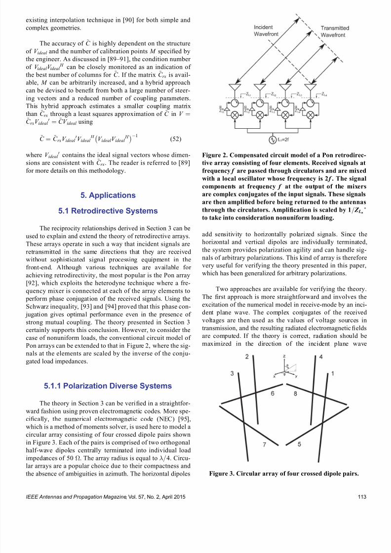
7232019 Unifying the Theory of Mutual Coupling Compensation in Antenna Arrays
httpslidepdfcomreaderfullunifying-the-theory-of-mutual-coupling-compensation-in-antenna-arrays 1019
existing interpolation technique in [90] for both simple and
complex geometries
The accuracy of ~C is highly dependent on the structure
of V ideal and the number of calibration points M speci1047297ed by
the engineer As discussed in [89 ndash 91] the condition number
of V ideal V ideal H can be closely monitored as an indication of
the best number of columns for ~C If the matrix ~C rx is avail-
able M can be arbitrarily increased and a hybrid approach
can be devised to bene1047297t from both a large number of steer-
ing vectors and a reduced number of coupling parametersThis hybrid approach estimates a smaller coupling matrix
than ~C rx through a least squares approximation of ~C in V frac14~C rxV ideal
0 frac14 ~CV ideal using
~C frac14 ~C rxV ideal 0V ideal
H V ideal V ideal H
1(52)
where V ideal 0 contains the ideal signal vectors whose dimen-
sions are consistent with ~C rx The reader is referred to [89]
for more details on this methodology
5 Applications
51 Retrodirective Systems
The reciprocity relationships derived in Section 3 can be
used to explain and extend the theory of retrodirective arrays
These arrays operate in such a way that incident signals are
retransmitted in the same directions that they are received
without sophisticated signal processing equipment in the
front-end Although various techniques are available for
achieving retrodirectivity the most popular is the Pon array
[92] which exploits the heterodyne technique where a fre-
quency mixer is connected at each of the array elements to perform phase conjugation of the received signals Using the
Schwarz inequality [93] and [94] proved that this phase con-
jugation gives optimal performance even in the presence of
strong mutual coupling The theory presented in Section 3
certainly supports this conclusion However to consider the
case of nonuniform loads the conventional circuit model of
Pon arrays can be extended to that in Figure 2 where the sig-
nals at the elements are scaled by the inverse of the conju-
gated load impedances
511 Polarization Diverse Systems
The theory in Section 3 can be veri1047297ed in a straightfor-
ward fashion using proven electromagnetic codes More spe-
ci1047297cally the numerical electromagnetic code (NEC) [95]
which is a method of moments solver is used here to model a
circular array consisting of four crossed dipole pairs shown
in Figure 3 Each of the pairs is comprised of two orthogonal
half-wave dipoles centrally terminated into individual load
impedances of 50 The array radius is equal to =4 Circu-
lar arrays are a popular choice due to their compactness and
the absence of ambiguities in azimuth The horizontal dipoles
add sensitivity to horizontally polarized signals Since the
horizontal and vertical dipoles are individually terminated
the system provides polarization agility and can handle sig-
nals of arbitrary polarizations This kind of array is therefore
very useful for verifying the theory presented in this paper
which has been generalized for arbitrary polarizations
Two approaches are available for verifying the theoryThe 1047297rst approach is more straightforward and involves the
excitation of the numerical model in receive-mode by an inci-
dent plane wave The complex conjugates of the received
voltages are then used as the values of voltage sources in
transmission and the resulting radiated electromagnetic 1047297elds
are computed If the theory is correct radiation should be
maximized in the direction of the incident plane wave
Figure 2 Compensated circuit model of a Pon retrodirec-
tive array consisting of four elements Received signals at
frequency f are passed through circulators and are mixed
with a local oscillator whose frequency is 2 f The signal
components at frequency f at the output of the mixers
are complex conjugates of the input signals These signalsare then ampli1047297ed before being returned to the antennas
through the circulators Ampli1047297cation is scaled by 1= Z Ln
to take into consideration nonuniform loading
Figure 3 Circular array of four crossed dipole pairs
IEEE Antennas and Propagation Magazine Vol 57 No 2 April 2015 113
7232019 Unifying the Theory of Mutual Coupling Compensation in Antenna Arrays
httpslidepdfcomreaderfullunifying-the-theory-of-mutual-coupling-compensation-in-antenna-arrays 1119
assuming an active implementation of the retrodirective sys-
tem where scattered 1047297elds can be ignored The second ap-
proach avoids a simulation in the receive-mode and computes
the coupling matrix of the system using the theory applicable
to receive systems in Section 3 This approach is favored
here since it will be reused in Section 52 Using the equa-
tions in Table 1 the current matrix required in the computa-
tion of the coupling matrix estimate takes the following form
I frac14
frac12 I z frac12 I xfrac12 I y
frac14
I11 I12 I18
I21 I22 I28
I31 I32 I38
I41 I42 I48
264 375I51 I52 I58
I61 I62 I68
I71 I72 I78
I81 I82 I88
26666666664
37777777775(53)
where is the segment length of the discretized dipoles and
the column vectors Iij contain the electric current distribu-
tions on dipole i due to the excitation of dipole j The dipoles
are modeled with thin wires hence currents are used in (53)
as opposed to current densities in (20) and the segment
length is used instead of the segment area s The wires
are assumed to be made of a PEC and all magnetic currents
are thus ignored This formulation assumes that the 1047297rst four
dipoles are vertical hence only z -directed currents are con-
sidered for these dipoles using submatrix frac12 I z The 1047297fth and
sixth dipoles are horizontal and oriented along the x-axis
hence only x-directed currents are considered for these two
dipoles using submatrix frac12 I x The seventh and eighth dipoles
are horizontal and oriented along the y-axis hence only y-
directed currents are considered for these two dipoles using sub-
matrix frac12 I y The ideal vector containing the incident signals takes
the following form
videal eth E E THORN
frac14
E sin
e j2
4
sin sinthornz1 coseth THORN
e j2
4
sin sinthornz2 coseth THORN
e j2
4
sin costhornz3 coseth THORN
e j2
4sin costhornz4 coseth THORN
26664
37775
eth E cos cos E sin THORN e j2 sin x5 costhorn
4sineth THORN
e j2 sin x6 cos
4sineth THORN
eth E cos sinthorn E cosTHORN e j2 sin
4costhorny7 sineth THORN
e j2
sin 4
costhorny8 sineth THORN
266666666666664
377777777777775
(54)
where the column vectors xn yn and zn contain the physical lo-
cations of the segments of the nth dipole It is implicitly as-
sumed in this formulation that the vertical and horizontal
dipoles are centered at eth x1 y1 z 1THORN frac14 eth x5 y5 z 5THORN frac14 eth0 =4 0THORN
eth x2 y2 z 2THORN frac14 eth x6 y6 z 6THORN frac14 eth0eth=4THORN 0THORN eth x3 y3 z 3THORN frac14 eth x7 y7 z 7THORN frac14eth=4 0 0THORN and eth x4 y4 z 4THORN frac14 eth x8 y8 z 8THORN frac14 etheth=4THORN 0 0THORN
respectively
The dipoles were discretized using 11 segments per di-
pole hence the coupling matrix estimate in reception ~C rx is
an 8 88 matrix The computation by NEC required ap-
proximately 65 kB of storage and 01 s of runtime to obtain
each column of (53) The received voltages can be estimated
for an arbitrary illumination using
vrxeth E E THORN frac14 ~C rxvideal eth E E THORN (55)
which requires 704 complex operations Since the array is
uniformly loaded the complex conjugate of (55) can be used
directly as the excitation of a transmit system of identical ge-
ometry and whose generator impedances are equal to the50- loads according to the following equation
vtx frac14 vrxeth E E THORN(56)
where ethTHORNdenotes the complex conjugate operation To con-
1047297rm that this is correct (55) is used to estimate the received
voltages for a vertically polarized signal arriving from azi-
muth angles frac14 0 30 60 and 90 for elevation angles
frac14 90 and 45 This is done by computing videal eth0 901 0THORN v ideal eth30 90 1 0THORN videal eth60 90 1 0THORN videal eth90 901 0THORN videal eth0 45 1 0THORN videal eth30 45 1 0THORN videal eth60 451 0THORN and videal eth90 45 1 0THORN using (54) and substituting this
into (55) These results are then substituted into (56) and used directly in a numerical simulation in transmission Volt-
age sources having the values contained in vtx are applied at
the element ports while including generator impedances
Z G frac14 50 and the -component of the radiated electric 1047297elds
are calculated using NEC Note that the horizontal dipoles do
not contribute to radiation for frac14 90 due to the vertical po-
larization of the incident signal but they do for frac14 45 be-
cause a horizontal incident 1047297eld exists for vertically polarized
signals arriving from 6frac14 90 The results are shown in
Figure 4 For comparison the results of a Van Atta imple-
mentation are also presented [96] In this case phase conju-
gation is attempted using vtx frac14 frac12vrx2 vrx1 vrx4 vrx3 vrx6 vrx5 vrx8 vrx7 T
It is seen in Figure 4 that the use of (56) gives very satisfying
performance in all the plotted scenarios since the transmitted
power is maximized in the directions of the incident signals
By comparing the radiation patterns for frac14 0 and frac14 90
it is veri1047297ed that the radiation patterns repeat in each quadrant
due to the symmetry of the system As discussed in [97] and
[98] the performance of the Van Atta implementation is seen
to be suboptimal due to mutual coupling effects with reduced
power levels in the directions of incident signals
512 Nonuniformly Loaded Systems
To evaluate the impact of ignoring nonuniform loading
the linear array shown in Figure 5 is now considered This ar-
ray consists of dipoles having lengths decreasing from 06to 03 as we move along the x-axis and whose loads are the
complex conjugate of their self-impedances The coupling
matrix can be estimated using the current matrix given by
I frac14 I z frac14
I11 I12 I17
I21 I22 I27
I71 I72 I77
264
375 (57)
IEEE Antennas and Propagation Magazine Vol 57 No 2 April 2015114
7232019 Unifying the Theory of Mutual Coupling Compensation in Antenna Arrays
httpslidepdfcomreaderfullunifying-the-theory-of-mutual-coupling-compensation-in-antenna-arrays 1219
The currents in (57) were computed using NEC which re-
quired approximately 54 kB of storage and less than 01 s of
runtime to obtain each column of matrix I with each of the el-
ements discretized into 11 segments Noting that the array el-
ements only respond to vertically polarized signals the parameters E and E can be ignored and the ideal signal
vector is given by
videal eth THORN frac14 sin
e j2 eth03 sin costhornz1 cos THORN
e j2
eth06 sin costhornz2 cos THORN
e j2
eth21 sin costhornz7 cos THORN
2664
3775 (58)
For a similar system used in transmission and having genera-
tor impedances given by Z G frac14 Z L the values of the voltage
sources are determined using
vtx frac14 Z L1vrxeth THORN
frac14 Z L
1~C rxvideal eth THORN
(59)
The -component of the radiated electric 1047297eld of the trans-
mit system is plotted in Figure 6 for an incident signal arriv-
ing from azimuth angles frac14 0 60 120 and 180 for
elevation angles frac14 90 and 45 For comparison the re-
sults are also shown when the nonuniform loading is ig-
nored This is equivalent to simply assuming that Z L is
proportional to the identity matrix in (59) It is observed
here that the consideration of nonuniform loading is critical
in the implementation of retrodirective systems otherwise
suboptimal performance is possible All the retrodirective
patterns obtained with proper consideration of nonuniform
loading are veri1047297ed to be satisfactory with their main beams
pointing in the directions of the incident signal These re-
sults strongly support the theory in Section 3 and the circuit
model in Figure 2
Figure 5 Nonuniform linear array of seven nonuniformly
loaded vertical dipoles Each dipole has a different length
and is terminated with a load impedance equal to the
complex conjugate of its self-impedance
Figure 6 Retrodirective radiation patterns of the nonuni-
form linear array of seven vertical dipoles in Figure 5 il-
luminated by a vertically polarized signal arriving from
frac14 0 frac14 60 frac14 120 and frac14 180 respectively (top
to bottom plots) The radiation patterns on the left are
for an elevation angle of 90 and those on the right are
for an elevation angle of 45 It is seen that the nonuni-
form loads must be carefully considered to obtain opti-
mized radiation with a main beam directed toward the
incident signal
Figure 4 Retrodirective radiation patterns of the circular
array of four crossed dipole pairs in Figure 3 illuminated
by a vertically polarized signal arriving from frac14 0
frac14 30 frac14 60 and frac14 90 respectively (top to bottom
plots) The radiation patterns on the left are for an eleva-
tion angle of 90 and those on the right are for an eleva-
tion angle of 45 The Pon implementation is seen to give
better results than the Van Atta due to mutual coupling
effects with optimized radiation and a main beam in the
direction of the incident signal
IEEE Antennas and Propagation Magazine Vol 57 No 2 April 2015 115
7232019 Unifying the Theory of Mutual Coupling Compensation in Antenna Arrays
httpslidepdfcomreaderfullunifying-the-theory-of-mutual-coupling-compensation-in-antenna-arrays 1319
52 ReceiveTransmit Beamforming
Beamforming is a popular application in receive an-
tenna systems for maximizing the reception of a desired sig-
nal while minimizing interference To perform beamforming
in transmission the directions and polarizations of distant re-
ceive systems must be known The reciprocity relationships
in Section 3 give us the con1047297dence to use received quantities
for transmission This is studied in this section where trans-
mit systems are calibrated using coupling matrices and sig-
nals processed in reception
521 Polarization Diverse Systems
The circular array of four crossed dipole pairs illus-
trated in Figure 3 is 1047297rst considered In accordance with the
theory in Section 3 since all the elements are terminated in
equal loads the receive coupling matrix estimate ~C rx de-
rived in Section 51 can also be used here to compensate
mutual coupling in transmission Unlike the retrodirective
system in Section 51 where coupling matrices were only
employed for analysis purposes the reduction of the matrix
size is desirable in a transmit beamformer to minimize the
memory requirement and computations in a practical imple-
mentation Using the hybrid approach introduced in
Section 4 the size of the matrix is further reduced to 8 40 for a total of 320 stored complex coupling parameters in-
stead of 704 This is done by subdividing each of the eight
dipoles into 1047297ve larger segments instead of the 11 used in
the numerical evaluation of ~C rx The column vectors xn yn
and zn in the ideal signal vector of (54) therefore consist of
1047297ve entries
Using the 8 40 matrix ~C obtained by (52) a correla-tion matrix assuming six uncorrelated signals is generated
using
R xx frac14 ~C X6
ifrac141
videal i i E i E i
videal i i E i E i
H
~C
H thorn 2o I N (60)
where ethTHORN H is the conjugate transpose operation i i E i
and E i are the arrival and polarization parameters describing
the ith signal I N is the identity matrix whose dimensions areequal to the number of array elements N frac14 8 and 2o frac14000001 is a 1047297ctitious noise power used for loading the diago-
nal of R xx to ensure a reasonable condition number The noise
is hereby modeled as uncorrelated zero-mean additive white
Gaussian This example considers a scenario involving six
signals at an elevation of frac14 45 Two of these are right-
hand circularly polarized (RHCP) signals arriving from frac140 and 60 two are left-hand circularly polarized (LHCP) sig-
nals arriving from frac14 30 and 30 one is a horizontally
polarized signal arriving from frac14 90 and one is a verti-
cally polarized signal arriving from frac14 120 Radiation is
optimized in the direction of the vertically polarized signal at
frac14 120 and all other signals are considered as interferers
The voltage sources of this system in transmission are then
determined using
vtx frac14 R xx1~C videal eth120 45 1 0THORN
(61)
Using these voltage sources in the numerical model in trans-
mission the radiated electric 1047297eld components E eth THORN and
E eth THORN are computed with NEC The radiation patterns in
transmission at an elevation of frac14 45 for the four different
polarizations of the signals are plotted in Figure 7 These pat-
terns are obtained through the following combinations of the
two orthogonal 1047297eld components
E veth THORN frac14 E eth THORN
E heth THORN frac14 E eth THORN
E RHCP eth THORN frac14 jE eth THORN thorn E eth THORN
E LHCP eth THORN frac14 E eth THORN thorn jE eth THORN (62)
where the subscripts v h RHCP and LHCP stand for verti-
cal horizontal right-hand circular and left-hand circular
polarizations respectively
The results in Figure 7 are very satisfying since nulls
are formed in transmission not only in the directions of the
1047297ve interferers but also with the correct polarizations and
thus con1047297rm that coupling matrices are effective in mutual
coupling compensation of both receive and transmit
Figure 7 Radiation patterns in transmission of the circular
array of four crossed dipole pairs in Figure 3 for receivers
of various polarizations at an elevation of 45 using an 8 40 coupling matrix estimate Radiation is maximized for a
vertically polarized receiver at 120 and minimized for a
horizontally polarized receiver at 90 LHCP receivers at
30 and 30 and RHCP receivers at 0 and 60 Mutual
coupling is compensated effectively with a main beam and
deep nulls forming in these directions
IEEE Antennas and Propagation Magazine Vol 57 No 2 April 2015116
7232019 Unifying the Theory of Mutual Coupling Compensation in Antenna Arrays
httpslidepdfcomreaderfullunifying-the-theory-of-mutual-coupling-compensation-in-antenna-arrays 1419
beamforming systems By reciprocity it is expected that an-
tennas both transmit and receive with the same polarizations
These results suggest that a wireless network can be opti-
mized when signals are transmitted and received using the
same antennas and proper mutual coupling compensation is
implemented Note that if the desired signal waveform is
known and all signals are being transmitted by distant sys-
tems vtx in (61) can also be determined through adaptive
techniques without knowledge of ~C and the desired signalrsquosdirection and polarization The theory presented in this paper
con1047297rms that both deterministic and adaptive approaches can
be effective in the optimization of wireless networks
522 Nonuniformly Loaded Systems
The nonuniform linear array of seven dipoles shown in
Figure 5 is now considered to study the impact of nonuni-
form loading in beamforming The coupling matrix of this
system in reception ~C rx derived in Section 51 is reduced
using the hybrid approach in Section 4 to a 7 35 ~C matrixfor a total of 245 stored complex coupling parameters in-
stead of 539 Although the dipoles are of different lengths a
reduced discretization scheme involving 1047297ve segments per
dipole is nonetheless used in this example The column
vector zn in the ideal signal vector of (58) therefore contains
1047297ve entries instead of the 11 entries used with the original
matrix
Using the 7 35 matrix ~C obtained by (52) and the
same six-signal scenario as in Section 521 the correlation
matrix estimated in reception ie R xx can be used to
determine the required voltage sources in transmission How-
ever nonuniform loading must be accounted for as follows
vtx frac14 Z L1 R xx Z L
H 1
h i1
Z L1~C videal eth120 45THORN
frac14 Z L H R xx
1~C videal eth120 45THORN
(63)
where the parameters E and E are ignored due to the pure
vertical polarization of the antenna system The resulting ra-
diation patterns in transmission are presented in Figure 8along with those obtained when nonuniform loading is
ignored It is seen that optimum beamforming is achieved
since the main beam is in the direction of the desired signal
while deep nulls form in the directions of the interferers As
already observed in Section 51 the main beam of the radia-
tion pattern is adversely affected when nonuniform loading is
ignored in a system where load impedances signi1047297cantly
vary It is seen that interference nulling would also signi1047297-
cantly suffer by the improper compensation of this transmit
system with attenuation of no more than 12 dB in the direc-
tions of the interferers
53 DOAPolarization Estimation
In some applications it is necessary to estimate the
DOA and polarization of incident signals Accurate mutual
coupling compensation is critical in such applications since it
directly affects the accuracy and resolution of the estimator
The eight-dipole array in front of a rectangular conducting
plate similar to that in [80] is considered here This antenna
system is illustrated in Figure 9 For 2-D operation the cou-
pling matrix is estimated as indicated in the 1047297gure The left
part of the matrix is associated with the dipoles and uses row
vectors cij whereas the rectangular conducting plate is subdi-
vided along the horizontal and vertical axes to account for
the variable horizontal and vertical phase shifts of incident
Figure 8 Radiation patterns in transmission of the non-
uniform linear array of seven vertical dipoles in Figure 5
for receivers at an elevation of 45 using a 7 35 cou-
pling matrix estimate Radiation needs to be maximized
at 120 and minimized at 60 30 0 30 and 60
It is seen that the nonuniform loads must be carefullyconsidered to obtain optimized radiation with properly
directed main beam and deep nulls
Figure 9 Geometry of the eight-dipole array in front of a
conducting plate for 2-D operation Eight row vectors as-
sociated with the dipoles 1047297ll the left part of the coupling
matrix for each of its rows whereas the other columns
are associated with the different portions of the plate
IEEE Antennas and Propagation Magazine Vol 57 No 2 April 2015 117
7232019 Unifying the Theory of Mutual Coupling Compensation in Antenna Arrays
httpslidepdfcomreaderfullunifying-the-theory-of-mutual-coupling-compensation-in-antenna-arrays 1519
signals Due to the 1047297nite dimensions of the conducting plate
the polarizations of the array elements may have horizontal
components and both horizontally and vertically oriented in-
cident 1047297elds have to be accounted for on the plate using the
complex scalar parameters C yij and C z
ij respectively
This antenna system is modeled with FEKO [99] using
the method of moments The dipoles are modeled by thin
wires having a length of 612 cm spaced 49 cm apart and
centrally terminated into 50- load impedances The rectan-
gular plate is modeled by a thin 3916-cm-wide and 24-cm-high perfectly conducting surface located 3 cm behind the
dipoles The numerical calculations are performed for an op-
erating frequency of 245 GHz Reordering the entries of the
right part of the matrix for mathematical conciseness the
coupling matrix estimate is obtained by the equations in
Table 1 with the current matrix having the following form
I frac14
z frac12 I wires
s J z J y
24 35frac14
z
I11 I18
I81 I88
24
35
s
J z 91 J z 98
J zK 1 J zK 8
J y91 J y98
J yK 1 J yK 8
2666666437777775
26666666666664
37777777777775
(64)
where z and s are the dipole segment length and conduct-
ing plate patch area respectively I ij is a column vector con-
taining the electric currents on the segments of element i due
to the excitation of element j and J yij and J zij are the y- and
z -directed electric current densities on patch i of the conduct-
ing plate due to the excitation of element j The ideal signal
vector of this problem takes the following form
videal eth E E THORN
frac14
E sin
e j 2 sin ethx1 cos thorny1 sin THORNthornz1 cos frac12
e j 2
sin ethx8 cos thorny8 sin THORNthornz8 cos frac12
e j 2 eth y9 sin sin thorn z 9 cos THORN
e j 2
eth y K sin sin thorn z K cos THORN
266666664
377777775
eth E cos sin thorn E cos THORN
e j2
eth y9 sin sin thorn z 9 cos THORN
e j2
eth y K sin sin thorn z K cos THORN
2
64
3
75
26666666666666664
37777777777777775
(65)
where x j y j and z j are column vectors containing the x y
and z physical locations of the wire segments for j 8 and
y j and z j are scalar values of the y and z locations of the con-
ducting plate patches for j 9 Note that this formulation
assumes that the conducting plate is located at x frac14 0 The nu-
merical solution of this problem involved a total of 104 wire
segments and 2923 surface patches which required approxi-
mately 150 MB of storage and 51 s of runtime to obtain each
of the columns of (64) Since two columns are required to
account for both y- and z -directed currents on each patch the
coupling matrix estimate turns out to be an 8 5950 matrix
Using the size-reduction guidelines presented in Section 4
the size of the estimate can be reduced at the expense of
some performance degradation Here the method is imple-
mented by subdividing the wires into 1047297ve segments each for
a total of 40 wire segments instead of 104 and the conduct-
ing plate into 70 patches 10 wide by 7 high instead of
2923 The size of the coupling matrix estimate then reduces
to 8 180 for a total of 1440 stored complex coupling pa-
rameters instead of 47 600 This is done by computing thesteering vectors for both vertically and horizontally polarized
signals arriving from 85 85 and 25 1725
with angular increments of 10 These two sets of steering
vectors are obtained by substituting videal eth 1 0THORN and
videal eth 0 1THORN as the columns of the matrix V ideal 0 in (52) for
324 different combinations of and Since two polariza-
tions are considered the total number of calibration points is
648 The matrix V ideal in (52) is then a 180 648 matrix con-
taining the ideal signal vectors for the reduced discretization
scheme and the 648 calibration points
The popular MUltiple SIgnal Classi1047297cation (MUSIC)algorithm described in [100 ndash 102] is employed here to per-
form DOA estimation in a polarization diverse scenario By
the theory of this paper the MUSIC DOA spectrum can be
expressed as
P eth THORN frac14 1
min eth A H ATHORN1 A H E N E N
H Ah i (66)
where
A frac14 ~C videal eth 1 0THORN videal eth 0 1THORNfrac12 (67)
minfrac12 is the smallest eigenvalue of the matrix inside the
brackets and E N is the matrix containing the noise eigen-
vectors obtained through the eigendecomposition of the cor-
relation matrix A signal scenario involving two plane waves
arriving from eth THORNfrac14eth30 60THORN and eth THORN frac14 eth0 45THORN re-
spectively is considered In addition the two signals are
circularly polarized The 1047297rst signal is RHCP ie eth E E THORN frac14eth j 1THORN whereas the second signal is LHCP ie eth E E THORN frac14eth1 j THORN The eigenvalue decomposition of the correlation matrix
provides six noise eigenvectors which are associated with
the six smallest eigenvalues to 1047297ll the matrix E N in (66) The
2-D DOA spectra are presented in Figure 10
For comparison the DOA spectra obtained without
compensation with a square coupling matrix having dimen-
sions 8 8 and with the full 8 5950 matrix are also
shown The accuracies and resolutions obtained with the
larger matrices in Figure 10c and d are seen to be signi1047297-
cantly better The reduced 8 180 matrix is seen to be a
very reasonable compromise with a slight performance degra-
dation but a reduction of approximately 97 of the memory
requirement and computations required for the evaluation of
the DOA spectra
IEEE Antennas and Propagation Magazine Vol 57 No 2 April 2015118
7232019 Unifying the Theory of Mutual Coupling Compensation in Antenna Arrays
httpslidepdfcomreaderfullunifying-the-theory-of-mutual-coupling-compensation-in-antenna-arrays 1619
It is important to note here that the 8 180 ~C matrixcan also be determined with measurements using (51) where
the matrix V is 1047297lled with measured steering vectors In the
case studied in this section 648 measured steering vectors
are necessary to obtain ~C This is a substantial reduction
compared with the number of measurements required for 2-D
operation using conventional means More details on this are
available in [89]
6 Conclusion
This paper has thoroughly reviewed the limitations of current mutual coupling compensation methods Through the
derivation of clear theoretical foundations that apply to both
receive and transmit systems the theory of mutual coupling
compensation was uni1047297ed to provide ef 1047297cient mutual coupling
compensation methods that can be employed with systems of
arbitrary geometries Reciprocity relationships were clearly
derived based on the receive and transmit formulations
thereby allowing the use of receive-mode compensation data
for both reception and transmission if the reciprocity relation-
ships are employed properly Both theoretical and experimen-
tal techniques can be used to evaluate mutual coupling by the
presented theory This theory can be veri1047297ed in a straight-forward fashion using proven electromagnetic codes and the
examples given in this paper on retrodirective systems beam-
formers and DOA estimation can be followed by the reader
for validation Finally this theory will likely 1047297nd several other
applications than those presented and contributes to the areas
of antenna theory mutual coupling analysis complex struc-
ture modeling and antenna measurements
7 AppendixDerivation of Analytical
Formulations in Table 1
The analytical formulations presented in Table 1 are
better understood using the various equivalent circuits of an-
tenna systems shown in Figure 11 In receive-mode the
open-circuit voltages are given by
voc A frac14 Z ANT I T videal (68)
voc L frac14 ethZ L thorn Z THORN I T
L videal (69)
voc frac14 ZI T scvideal (70)
Figure 10 2-D DOA estimation using the eight-dipole linear array in front of a rectangular con-
ducting plate for two circularly polarized signals from eth THORN frac14 eth30 60THORN and eth0 45THORN using
MUSIC Mutual coupling compensation implemented with an 8 180 coupling matrix estimate is
seen to give very satisfying performance and ef 1047297ciency with sharp peaks toward the two signals
IEEE Antennas and Propagation Magazine Vol 57 No 2 April 2015 119
7232019 Unifying the Theory of Mutual Coupling Compensation in Antenna Arrays
httpslidepdfcomreaderfullunifying-the-theory-of-mutual-coupling-compensation-in-antenna-arrays 1719
This is consistent with classic antenna theory presented in
[6] The port voltages should be equal irrespective of the
method By circuit theory these are given by
vrx frac14 Z LethZ L thorn Z ANT THORN1
voc A (71)
frac14 Z LethZ L thorn Z THORN1voc L
(72)
frac14 Z LethZ L thorn Z THORN1voc (73)
Substituting (68) ndash (70) into (71) ndash (73) and performing some
matrix manipulations gives
vrx frac14 Z LethZ L thorn Z ANT THORN1
Z ANT I T videal (74)
frac14 Z L I T L videal (75)
frac14 Z LethZ L thorn Z THORN1ZI T
scvideal (76)
The admittance formulations are obtained by substituting
Z L frac14 Y L1 Z ANT frac14 Y ANT
1 and Z frac14 Y 1 into (74) ndash (76) For
example (76) gives
vrx frac14 Y 1 L Y 1
L thorn Y 1 1
Y 1 I T scvideal
frac14 Y 1 L Y LethY L thorn Y THORN1
YY 1 I T scvideal
frac14 ethY L thorn Y THORN1 I T
scvideal (77)
In transmit-mode the radiated 1047297elds are scaled by v A v L
and v which are obtained by voltage division in 1) and 3)
In 2) v L is simply equal to vtx The admittance formulations
in transmit-mode are obtained in the same fashion as the ex-
ample of (77)
8 References
[1] H S Lui H T Hui and M S Leong ldquoA note on the mutualcoupling problems in transmitting and receiving antenna arraysrdquo IEEE Antennas Propag Mag vol 51 no 5 pp 171 ndash 176 Oct 2009
[2] C A Balanis Antenna Theory Analysis and Design 2nd ed NewYork NY USA Wiley 1997
[3] R C Hansen Phased Array Antennas New York NY USA Wiley1998
[4] T A Milligan Modern Antenna Design 2nd ed New York NYUSA Wiley 2005
[5] R J Mailloux Phased Array Antenna Handbook 2nd ed BostonMA USA Artech House 2005[6] S A Schelkunoff and H T Friis Antennas Theory and Practice
New York NY USA Wiley 1952[7] R P Meys ldquoA summary of the transmitting and receiving properties
of antennasrdquo IEEE Antennas Propag Mag vol 42 no 3 pp 49 ndash 53Jun 2000
[8] S Henault ldquoEvaluation of electromagnetic coupling in antenna sys-tems A uni1047297ed theory and its applicationsrdquo PhD dissertation DeptElect Comput Eng Royal Military College of Canada KingstonON Canada Jan 2012
[9] S Henault Y M M Antar S Rajan R Inkol and S Wang ldquoThemultiple antenna induced EMF method for the precise calculation of thecoupling matrix in a receiving antenna arrayrdquo Progr Electromagn Res M vol 8 pp 103 ndash 118 2009
[10] P S Carter ldquoCircuit relations in radiating systems and applications toantenna problemsrdquo Proc IRE vol 20 no 6 pp 1004 ndash 1041 Jun 1932
[11] H E King ldquoMutual impedance of unequal length antennas in echelonrdquo IRE Trans Antennas Propag vol AP-5 no 3 pp 306 ndash 313 Jul 1957
[12] J H Richmond and N H Geary ldquoMutual impedance of nonplanar-skew sinusoidal dipolesrdquo IEEE Trans Antennas Propag vol AP-23no 3 pp 412 ndash 414 May 1975
[13] J D Kraus Antennas 2nd ed New York NY USA McGraw-Hill1988
[14] S A Mitilineos C A Papagianni G I Verikaki and C N CapsalisldquoDesign of switched beam planar arrays using the method of geneticalgorithmsrdquo Progr Electromagn Res vol 46 pp 105 ndash 126 2004
[15] A W Love ldquoComment On the equivalent circuit of a receiving antennardquo IEEE Antennas Propag Mag vol 44 no 5 pp 124 ndash 125 Oct 2002
[16] J B Andersen and R G Vaughan ldquoTransmitting receiving and scat-tering properties of antennasrdquo IEEE Antennas Propag Mag vol 45no 4 pp 93 ndash 98 Aug 2003
[17] J Van Bladel ldquoOn the equivalent circuit of a receiving antennardquo
IEEE Antennas Propag Mag vol 44 no 1 pp 164 ndash
165 Feb 2002[18] R E Collin ldquoLimitations on the Thevenin and Norton equivalent cir-cuits for a receiving antennardquo IEEE Antennas Propag Mag vol 45no 2 pp 119 ndash 124 Apr 2003
[19] C T Tai ldquoA Critical study of the circuit relations of two distant an-tennasrdquo IEEE Antennas Propag Mag vol 44 no 6 pp 32 ndash 37Dec 2002
[20] C T Tai ldquoCorrection V A critical study of the circuit relations of twodistant antennasrdquo IEEE Antennas Propag Mag vol 45 no 1 p 125Feb 2003
[21] A W Love ldquoCorrection V A critical study of the circuit relations of twodistant antennasrdquo IEEE Antennas Propag Mag vol 45 no 2 p 42Apr 2003
[22] C G Montgomery R H Dicke and E M Purcell Principles of Microwave Circuits New York NY USA McGraw-Hill 1948
[23] S Ramo and J Whinnery Fields and Waves in Modern Radio 2nd ed New York NY USA Wiley 1953
[24] S Silver Microwave Antenna Theory and Design New York NYUSA McGraw-Hill 1949
[25] R C Hansen ldquoRelationships between antennas as scatterers and asradiatorsrdquo Proc IEEE vol 77 no 5 pp 659 ndash 662 May 1989
[26] C C Su ldquoOn the equivalent generator voltage and generator internalimpedance for receiving antennasrdquo IEEE Trans Antennas Propagvol 51 no 2 pp 279 ndash 285 Feb 2003
[27] S R Best and B C Kaanta ldquoA tutorial on the receiving and scattering properties of antennasrdquo IEEE Antennas Propag Mag vol 51 no 5 pp 26 ndash 37 Oct 2009
[28] J W Wallace and R Mehmood ldquoOn the accuracy of equivalent circuit models for multi-antenna systemsrdquo IEEE Trans Antennas Propagvol 60 no 2 pp 540 ndash 547 Feb 2012
[29] D M Pozar ldquoThe active element patternrdquo IEEE Trans Antennas Pro- pag vol 42 no 8 pp 1176 ndash 1178 Aug 1994
Figure 11 Equivalent circuits of (left) transmit and (right)
receive antenna systems for the three different loading con-
ditions given in Table 1 These equivalent circuits use vec-
tors and matrices to represent voltages and impedances
IEEE Antennas and Propagation Magazine Vol 57 No 2 April 2015120
7232019 Unifying the Theory of Mutual Coupling Compensation in Antenna Arrays
httpslidepdfcomreaderfullunifying-the-theory-of-mutual-coupling-compensation-in-antenna-arrays 1819
[30] D F Kelley and W L Stutzman ldquoArray antenna pattern modelingmethods that include mutual coupling effectsrdquo IEEE Trans Antennas Propag vol 41 no 12 pp 1625 ndash 1632 Dec 1993
[31] K Takamizawa ldquoAnalysis of highly coupled wideband antenna arraysusing scattering parameter network modelsrdquo PhD dissertation DeptElect Comput Eng Virginia Polytech Inst State Univ BlacksburgVA USA Dec 2002
[32] D M Pozar ldquoA relation between the active input impedance and theactive element pattern of a phased arrayrdquo IEEE Trans Antennas Propag vol 51 no 9 pp 2486 ndash 2489 Sep 2003
[33] D F Kelley ldquoRelationships between active element patterns and mutual impedance matrices in phased array antennasrdquo in Proc IEEE Int Symp Antennas Propag 2002 pp 524 ndash 527
[34] D F Kelley ldquo
Embedded element patterns and mutual impedancematrices in the terminated phased array environmentrdquo in Proc IEEE Int Symp Antennas Propag 2005 pp 659 ndash 662
[35] R F Harrington ldquoAntenna excitation for maximum gainrdquo IEEE Trans Antennas Propag vol AP-13 no 6 pp 896 ndash 903 Nov 1965
[36] H Rogier and E Bonek ldquoAnalytical spherical-mode-based compensa-tion of mutual coupling in uniform circular arrays for direction-of-arrivalestimationrdquo Int J Electron Commun vol 60 no 3 pp 179 ndash 189Mar 2006
[37] A T De Hoop ldquoThe N-port receiving antenna and its equivalent elec-trical networkrdquo Philips Res Rep vol 30 pp 302 ndash 315 1975
[38] P S Kildal ldquoEquivalent circuits of receive antennas in signal process-ing arraysrdquo Microw Opt Technol Lett vol 21 no 4 pp 244 ndash 246May 1999
[39] K F Warnick B Woestenburg L Belostotski and P Russer ldquoMinimiz-ing the noise penalty due to mutual coupling for a receiving arrayrdquo IEEE Trans Antennas Propag vol 57 no 6 pp 1634 ndash 1644 Jun 2009
[40] R O Schmidt ldquoMultilinear array manifold interpolationrdquo IEEE TransSignal Process vol 40 no 4 pp 857 ndash 866 Apr 1992
[41] A J Weiss and B Friedlander ldquoManifold interpolation for diversely po-larized arraysrdquo Proc Inst Elect Eng V Radar Sonar Navig vol 141no 1 pp 19 ndash 24 Feb 1994
[42] R J Allard and D H Werner ldquoThe model-based parameter estimationof antenna radiation patterns using windowed interpolation and sphericalharmonicsrdquo IEEE Trans Antennas Propag vol 51 no 8 pp 1891 ndash 1906 Aug 2003
[43] M Landmann and G Del Galdo ldquoEf 1047297cient antenna description for MIMO channel modelling and estimationrdquo in Proc 7th Eur ConfWireless Technol Amsterdam The Netherlands 2004 pp 217 ndash 220
[44] G Del Galdo J Lotze M Landmann and M Haardt ldquoModelling and manipulation of polarimetric antenna beam patterns via sphericalharmonicsrdquo in Proc 14th Eur Signal Process Conf Florence ItalySep 2006 pp 1 ndash 5
[45] F Belloni A Richter and V Koivunen ldquo
DoA estimation via manifold separation for arbitrary array structuresrdquo IEEE Trans Signal Processvol 55 no 10 pp 4800 ndash 4810 Oct 2007
[46] H T Hui ldquoDecoupling methods for the mutual coupling effect in an-tenna arrays A reviewrdquo Recent Patents Eng vol 1 no 2 pp 187 ndash 193 Jun 2007
[47] T Su and H Ling ldquoOn modeling mutual coupling in antenna arraysusing the coupling matrixrdquo Microw Opt Technol Lett vol 28 no 4 pp 231 ndash 237 Feb 2001
[48] P Darwood P N Fletcher and G S Hilton ldquoMutual couplingcompensation in small planar array antennasrdquo Proc Inst Elect Eng V
Microw Antennas Propag vol 145 no 1 pp 1 ndash 6 Feb 1998[49] H Steyskal and J S Herd ldquoMutual coupling compensation in small array
antennasrdquo IEEE Trans Antennas Propag vol 38 no 12 pp 1971 ndash 1975 Dec 1990
[50] I J Gupta and A A Ksienski ldquoEffect of mutual coupling on the performance of adaptive arraysrdquo IEEE Trans Antennas Propag
vol AP-31 no 5 pp 785 ndash 791 Sep 1983[51] C C Yeh M L Leou and D R Ucci ldquoBearing estimations with mu-
tual coupling presentrdquo IEEE Trans Antennas Propag vol 37 no 10 pp 1332 ndash 1335 Oct 1989
[52] C Roller and W Wasylkiwskyj ldquoEffects of mutual coupling on super-resolution DF in linear arraysrdquo in Proc IEEE Int Conf AcoustSpeech Signal Process vol 5 1992 pp 257 ndash 260
[53] Z Huang C A Balanis and C R Birtcher ldquoMutual couplingcompensation in UCAs Simulations and experimentrdquo IEEE Trans Antennas Propag vol 54 no 11 pp 3082 ndash 3086 Nov 2006
[54] K C Lee and T H Chu ldquoA circuit model for mutual couplinganalysis of a 1047297nite antenna arrayrdquo IEEE Trans Electromagn Compatvol 38 no 3 pp 483 ndash 489 Aug 1996
[55] K W Lo and T B Vu ldquoSimple S-parameter model for receiving an-tenna arrayrdquo Electron Lett vol 24 no 20 pp 1264 ndash 1266 Sep 1988
[56] K M Pasala and E M Friel ldquoMutual coupling effects and their reduction in wideband direction of arrival estimationrdquo IEEE Trans Aerosp Electron Syst vol 30 no 4 pp 1116 ndash 1122 Apr 1994
[57] R S Adve and T K Sarkar ldquoCompensation for the effects of mutualcoupling on direct data domain adaptive algorithmsrdquo IEEE Trans An-tennas Propag vol 48 no 1 pp 86 ndash 94 Jan 2000
[58] R F Harrington Field Computation by Moment Methods New York NY USA Wiley 1968
[59] J Pierre and M Kaveh ldquoExperimental performance of calibration and direction-1047297nding algorithmsrdquo in Proc IEEE Int Conf Acoust SpeechSignal Process vol 2 Toronto ON Canada Apr 1991 pp 1365 ndash 1368
[60] T Su K Dandekar and H Ling ldquoSimulation of mutual couplingeffect in circular arrays for direction-1047297nding applicationsrdquo Microw
Opt Technol Lett vol 26 no 5 pp 331 ndash
336 Sep 2000[61] K R Dandekar H Ling and G Xu ldquoExperimental study of mutualcoupling compensation in smart antenna applicationsrdquo IEEE TransWireless Commun vol 1 no 3 pp 480 ndash 487 Jul 2002
[62] H T Hui ldquoReducing the mutual coupling effect in adaptive nullingusing a re-de1047297ned mutual impedancerdquo IEEE Microw Wireless Compon Lett vol 12 no 5 pp 178 ndash 180 May 2002
[63] H T Hui ldquoCompensating for the mutual coupling effect in direction1047297nding based on a new calculation method for mutual impedancerdquo IEEE Antennas Wireless Propag Lett vol 2 no 1 pp 26 ndash 29 2003
[64] H T Hui ldquoImproved compensation for the mutual coupling effect ina dipole array for direction 1047297ndingrdquo IEEE Trans Antennas Propagvol 51 no 9 pp 2498 ndash 2503 Sep 2003
[65] H T Hui ldquoA practical approach to compensate for the mutual couplingeffect in an adaptive dipole arrayrdquo IEEE Trans Antennas Propagvol 52 no 5 pp 1262 ndash 1269 May 2004
[66] H T Hui ldquoA new de1047297nition of mutual impedance for application in di-
pole receiving antenna arraysrdquo IEEE Antennas Wireless Propag Lettvol 3 no 1 pp 364 ndash 367 Dec 2004
[67] S Henault and Y M M Antar ldquoWideband analysis of mutual couplingcompensation methodsrdquo Int J Antennas Propag vol 2011 2011Art ID 756 153
[68] B Friedlander and A J Weiss ldquoDirection 1047297nding in the presence of mutual couplingrdquo IEEE Trans Antennas Propag vol 39 no 3 pp 273 ndash 284 Mar 1991
[69] E K L Hung ldquoA critical study of a self-calibrating direction-1047297ndingmethod for arraysrdquo IEEE Trans Signal Process vol 42 no 2 pp 471 ndash 474 Feb 1994
[70] F S Sellone and A Serra ldquoA novel online mutual coupling compen-sation algorithm for uniform and linear arraysrdquo IEEE Trans Signal Process vol 55 no 2 pp 560 ndash 573 Feb 2007
[71] M Lin and L Yang ldquoBlind calibration and DOA estimation with uni-form circular arrays in the presence of mutual couplingrdquo IEEE Anten-
nas Wireless Propag Lett vol 5 no 1 pp 315 ndash
318 Dec 2006[72] D Y Gao B H Wang and Y Guo ldquoComments on lsquoBlind calibrationand DOA estimation with uniform circular arrays in the presence of mutual couplingrsquordquo IEEE Antennas Wireless Propag Lett vol 5 no 1 pp 566 ndash 568 Dec 2006
[73] M Lin and L Yang ldquoReply to the comments on lsquoBlind calibration and DOA estimation with uniform circular arrays in the presence of mutualcouplingrsquordquo IEEE Antennas Wireless Propag Lett vol 5 no 1 pp 568 ndash 569 Dec 2006
[74] Q Bao C C Ko and W Zhi ldquoDOA estimation under unknownmutual coupling and multipathrdquo IEEE Trans Aerosp Electron Systvol 41 no 2 pp 565 ndash 573 Apr 2005
[75] Z Ye and C Liu ldquoOn the resiliency of MUSIC direction 1047297nding against antenna sensor couplingrdquo IEEE Trans Antennas Propag vol 56no 2 pp 371 ndash 380 Feb 2008
[76] Z Ye and C Liu ldquo2-D DOA estimation in the presence of mutualcouplingrdquo IEEE Trans Antennas Propag vol 56 no 10 pp 3150 ndash
3158 Oct 2008[77] Y Zhang Q Wan and A M Huang ldquoLocalization of narrow band
sources in the presence of mutual coupling via sparse solution 1047297ndingrdquo Progr Electromagn Res vol 86 pp 243 ndash 257 2008
[78] T Svantesson ldquoAntennas and propagation from a signal processing perspectiverdquo PhD dissertation Dept Signals Syst Chalmers UnivTechnol Goumlteborg Sweden 2001
[79] S Henault and Y M M Antar ldquoLimitations of online calibrationmethodsrdquo in Proc IEEE Int Symp Antennas Propag Toronto ONCanada Jul 2010 pp 1 ndash 4
[80] I J Gupta et al ldquoAn experimental study of antenna array calibrationrdquo IEEE Trans Antennas Propag vol 51 no 3 pp 664 ndash 667 Mar 2003
[81] C K E Lau R S Adve and T K Sarkar ldquoMinimum norm mutual cou- pling compensation with applications in direction of arrival estimationrdquo IEEE Trans Antennas Propag vol 52 no 8 pp 2034 ndash 2041 Aug 2004
IEEE Antennas and Propagation Magazine Vol 57 No 2 April 2015 121
7232019 Unifying the Theory of Mutual Coupling Compensation in Antenna Arrays
httpslidepdfcomreaderfullunifying-the-theory-of-mutual-coupling-compensation-in-antenna-arrays 1919
[82] Q Y Yuan Q Chen and K Sawaya ldquoAccurate DOA estimation usingarray antenna with arbitrary geometryrdquo IEEE Trans Antennas Propagvol 53 no 4 pp 1352 ndash 1357 Apr 2005
[83] S Henault Y M M Antar S Rajan R Inkol and S Wang ldquoEffectsof mutual coupling on the accuracy of adcock direction 1047297nding systemsrdquo IEEE Trans Aerosp Electron Syst vol 48 no 4 pp 2990 ndash 3005Oct 2012
[84] T Su and H Ling ldquoOn the simultaneous modeling of array mutualcoupling and array-platform interactionsrdquo Microw Opt Technol Lettvol 33 no 3 pp 167 ndash 171 May 2002
[85] A Ferreol E Boyer P Larzabal and M Haardt ldquoOn the introductionof an extended coupling matrix for a 2D bearing estimation with an ex- perimental RF systemrdquo Signal Process vol 87 no 9 pp 2005 ndash 2016
Sep 2007[86] J B Andersen and H H Rasmussen ldquoDecoupling and descatteringnetworks for antennasrdquo IEEE Trans Antennas Propag vol AP-24no 6 pp 841 ndash 846 Nov 1976
[87] M Kragalott M S Kluskens D A Zolnick W M Dorsey and J A Valenzi ldquoA toolset independent hybrid method for calculatingantenna couplingrdquo IEEE Trans Antennas Propag vol 59 no 2 pp 443 ndash 451 Feb 2011
[88] A E H Love ldquoThe integration of equations of propagation of electricwavesrdquo Philos Trans Roy Soc London A Math Phys Sci vol 197 pp 1 ndash 45 1901
[89] S Henault S K Podilchak S M Mikki and Y M M Antar ldquoA meth-odology for mutual coupling estimation and compensation in antennasrdquo IEEE Trans Antennas Propag vol 61 no 3 pp 1119 ndash 1131Mar 2013
[90] S Henault and Y M M Antar ldquoOn the interpolation of radiation pat-terns in the calibration of antenna arraysrdquo in IEEE Int Symp Antennas
Propag Spokane WA USA Jul 2011 pp 1747 ndash 1750[91] S Henault and Y M M Antar ldquoA hybrid approach for antenna array
calibrationrdquo in Proc IEEE Int Symp Antennas Propag SpokaneWA USA Jul 2011 pp 1751 ndash 1754
[92] C Pon ldquoRetrodirective array using the heterodyne techniquerdquo IEEE Trans Antennas Propag vol 12 no 2 pp 176 ndash 180 Mar 1964
[93] A F Kay ldquoComments on self-phasing array antennas and electronicallyadaptive antenna systemsrdquo IEEE Trans Antennas Propag vol AP-12no 6 pp 792 ndash 793 Nov 1964
[94] V F Fusco ldquoResponse of retrodirective array in the presence of multi- ple spatially separated sourcesrdquo IEEE Trans Antennas Propag vol 54no 4 pp 1352 ndash 1354 Apr 2006
[95] NEC-2 Manual Lawrence Livermore National Laboratory LivermoreCA USA 1996
[96] L C Van Atta ldquoElectromagnetic re1047298ectorrdquo US Patent 2 908 002Oct 6 1959
[97] T Larsen ldquo
Re1047298
ector arraysrdquo
IEEE Trans Antennas Propag vol AP-14no 6 pp 689 ndash 693 Nov 1966[98] J Appel-Hansen ldquoA van Atta re1047298ector consisting of half-wave dipolesrdquo
IEEE Trans Antennas Propag vol AP-14 no 6 pp 694 ndash 700 Nov 1966
[99] FEKO-Comprehensive EM Solutions [Online] Available httpwwwfekoinfo
[100] R O Schmidt ldquoMultiple emitter location and signal parameter estima-tionrdquo IEEE Trans Antennas Propag vol AP-34 no 3 pp 276 ndash 280Mar 1986
[101] R O Schmidt and R Franks ldquoMultiple source DF signal processingAn experimental systemrdquo IEEE Trans Antennas Propag vol AP-34no 3 pp 281 ndash 290 Mar 1986
[102] E R Ferrara and T M Parks ldquoDirection 1047297nding with an array of antennas having diverse polarizationsrdquo IEEE Trans Antennas Propagvol AP-31 no 2 pp 231 ndash 236 Mar 1983
Simon Henault received the BEng degreefrom Laval University Queacutebec City QCCanada in 2001 and the MASc and PhDdegrees from the Royal Military College of Canada Kingston ON Canada in 2008 and 2012 respectively all in electrical engineering
Since 1998 he has been with CanadarsquosDepartment of National Defence in variouscapacities including two years as a facultymember with the Royal Military College of Canada and multiple assignments with De-fence Research and Development CanadaHe has expertise in antenna radio frequency
and signal processing systems employed in a variety of electronic warfarespace communication and unmanned aerial vehicle platforms
Dr Henault is a regular Reviewer for several journals and conferences
Yahia M M Antar (Srsquo73 ndash Mrsquo76 ndash SMrsquo85 ndash LFrsquo00) received the BSc (Hons) degree fromAlexandria University Alexandria Egypt in1966 and the MSc and PhD degrees fromthe University of Manitoba Winnipeg MBCanada in 1971 and 1975 respectively all inelectrical engineering
In 1977 he held a Government of Canada
Visiting Fellowship with the Communica-tions Research Centre Ottawa ON Canadawhere he worked with the Space TechnologyDirectorate on communications antennas for satellite systems In May 1979 he joined the
Division of Electrical Engineering National Research Council of CanadaOttawa where he worked on polarization radar applications in remote sens-ing of precipitation radio wave propagation electromagnetic scatteringand radar cross-section investigations In November 1987 he joined thestaff of the Department of Electrical and Computer Engineering Royal Mil-itary College of Canada Kingston ON where he has held the position of Professor since 1990 and is currently the Vice Dean for defense and secu-rity research He has authored or coauthored about 200 journal papersmany chapters in books and about 400 refereed conference papers holdsseveral patents has chaired several national and international conferencesand has given plenary talks at many conferences He has supervised and cosupervised over 80 PhD and MSc theses at the Royal Military Collegeof Canada and at Queenrsquos University Kingston several of which have re-ceived the Governor General of Canada Gold Medal the outstanding PhDthesis of the Division of Applied Science as well as many Best Paper Awardsin major international symposia He served as the Chairman of the Canadian Nationa l Commis sion for Radio Scienc e (CNC URSI 1999 ndash 2008) and the Commission B National Chair (1993 ndash 1999) and held an adjunct ap- pointme nt at the Univer sity of Manito ba and has a cross appoint ment at Queenrsquos University
Dr Antar is a Fellow of the Engineering Institute of Canada and theElectromagnetic Academy He serves as an Associate Editor for the IEEEA NTENNAS AND PROPAGATION MAGAZINE served as an Associate Editor for the IEEE TRANSACTIONS ON A NTENNAS AND PROPAGATION and theIEEE A NTENNAS AND WIRELESS PROPAGATION LETTERS and was a mem- ber of the Editorial Board of the International Journal of RF and MicrowaveComputer-Aided Engineering He served on Natural Sciences and Engineer-ing Research Council of Canada grant selection and strategic grant commit-
tees on Ontario Early Research Awards panels and on review panels for the National Science Foundation In May 2002 he was awarded a Tier 1Canada Research Chair in Electromagnetic Engineering which has been re-newed in 2009 In 2003 he was awarded the Royal Military College of Canada ldquoExcellence in Researchrdquo Prize and the RMCC Class of 1965Teaching Excellence Award in 2012 He was elected by the Council of theInternational Union of Radio Science to the Board as Vice President in Au-gust 2008 and in 2013 and to the IEEE Antennas and Propagation SocietyAdministration Committee in December 2009 On January 31 2011 he wasappointed Member of the Canadian Defence Science Advisory Board He ison the IEEE Antennas and Propagation Society Distinguished LecturersProgram In October 2012 he received the Queenrsquos Diamond Jubilee Medalfrom the Governor General of Canada in recognition of his contribution toCanada He was a recipient of the 2014 IEEE Canada RA Fessenden Silver Medal and the 2015 IEEE Canada J M Ham Outstanding EngineeringEducation Award
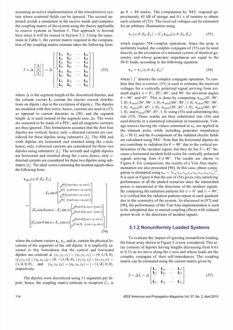
7232019 Unifying the Theory of Mutual Coupling Compensation in Antenna Arrays
httpslidepdfcomreaderfullunifying-the-theory-of-mutual-coupling-compensation-in-antenna-arrays 1119
assuming an active implementation of the retrodirective sys-
tem where scattered 1047297elds can be ignored The second ap-
proach avoids a simulation in the receive-mode and computes
the coupling matrix of the system using the theory applicable
to receive systems in Section 3 This approach is favored
here since it will be reused in Section 52 Using the equa-
tions in Table 1 the current matrix required in the computa-
tion of the coupling matrix estimate takes the following form
I frac14
frac12 I z frac12 I xfrac12 I y
frac14
I11 I12 I18
I21 I22 I28
I31 I32 I38
I41 I42 I48
264 375I51 I52 I58
I61 I62 I68
I71 I72 I78
I81 I82 I88
26666666664
37777777775(53)
where is the segment length of the discretized dipoles and
the column vectors Iij contain the electric current distribu-
tions on dipole i due to the excitation of dipole j The dipoles
are modeled with thin wires hence currents are used in (53)
as opposed to current densities in (20) and the segment
length is used instead of the segment area s The wires
are assumed to be made of a PEC and all magnetic currents
are thus ignored This formulation assumes that the 1047297rst four
dipoles are vertical hence only z -directed currents are con-
sidered for these dipoles using submatrix frac12 I z The 1047297fth and
sixth dipoles are horizontal and oriented along the x-axis
hence only x-directed currents are considered for these two
dipoles using submatrix frac12 I x The seventh and eighth dipoles
are horizontal and oriented along the y-axis hence only y-
directed currents are considered for these two dipoles using sub-
matrix frac12 I y The ideal vector containing the incident signals takes
the following form
videal eth E E THORN
frac14
E sin
e j2
4
sin sinthornz1 coseth THORN
e j2
4
sin sinthornz2 coseth THORN
e j2
4
sin costhornz3 coseth THORN
e j2
4sin costhornz4 coseth THORN
26664
37775
eth E cos cos E sin THORN e j2 sin x5 costhorn
4sineth THORN
e j2 sin x6 cos
4sineth THORN
eth E cos sinthorn E cosTHORN e j2 sin
4costhorny7 sineth THORN
e j2
sin 4
costhorny8 sineth THORN
266666666666664
377777777777775
(54)
where the column vectors xn yn and zn contain the physical lo-
cations of the segments of the nth dipole It is implicitly as-
sumed in this formulation that the vertical and horizontal
dipoles are centered at eth x1 y1 z 1THORN frac14 eth x5 y5 z 5THORN frac14 eth0 =4 0THORN
eth x2 y2 z 2THORN frac14 eth x6 y6 z 6THORN frac14 eth0eth=4THORN 0THORN eth x3 y3 z 3THORN frac14 eth x7 y7 z 7THORN frac14eth=4 0 0THORN and eth x4 y4 z 4THORN frac14 eth x8 y8 z 8THORN frac14 etheth=4THORN 0 0THORN
respectively
The dipoles were discretized using 11 segments per di-
pole hence the coupling matrix estimate in reception ~C rx is
an 8 88 matrix The computation by NEC required ap-
proximately 65 kB of storage and 01 s of runtime to obtain
each column of (53) The received voltages can be estimated
for an arbitrary illumination using
vrxeth E E THORN frac14 ~C rxvideal eth E E THORN (55)
which requires 704 complex operations Since the array is
uniformly loaded the complex conjugate of (55) can be used
directly as the excitation of a transmit system of identical ge-
ometry and whose generator impedances are equal to the50- loads according to the following equation
vtx frac14 vrxeth E E THORN(56)
where ethTHORNdenotes the complex conjugate operation To con-
1047297rm that this is correct (55) is used to estimate the received
voltages for a vertically polarized signal arriving from azi-
muth angles frac14 0 30 60 and 90 for elevation angles
frac14 90 and 45 This is done by computing videal eth0 901 0THORN v ideal eth30 90 1 0THORN videal eth60 90 1 0THORN videal eth90 901 0THORN videal eth0 45 1 0THORN videal eth30 45 1 0THORN videal eth60 451 0THORN and videal eth90 45 1 0THORN using (54) and substituting this
into (55) These results are then substituted into (56) and used directly in a numerical simulation in transmission Volt-
age sources having the values contained in vtx are applied at
the element ports while including generator impedances
Z G frac14 50 and the -component of the radiated electric 1047297elds
are calculated using NEC Note that the horizontal dipoles do
not contribute to radiation for frac14 90 due to the vertical po-
larization of the incident signal but they do for frac14 45 be-
cause a horizontal incident 1047297eld exists for vertically polarized
signals arriving from 6frac14 90 The results are shown in
Figure 4 For comparison the results of a Van Atta imple-
mentation are also presented [96] In this case phase conju-
gation is attempted using vtx frac14 frac12vrx2 vrx1 vrx4 vrx3 vrx6 vrx5 vrx8 vrx7 T
It is seen in Figure 4 that the use of (56) gives very satisfying
performance in all the plotted scenarios since the transmitted
power is maximized in the directions of the incident signals
By comparing the radiation patterns for frac14 0 and frac14 90
it is veri1047297ed that the radiation patterns repeat in each quadrant
due to the symmetry of the system As discussed in [97] and
[98] the performance of the Van Atta implementation is seen
to be suboptimal due to mutual coupling effects with reduced
power levels in the directions of incident signals
512 Nonuniformly Loaded Systems
To evaluate the impact of ignoring nonuniform loading
the linear array shown in Figure 5 is now considered This ar-
ray consists of dipoles having lengths decreasing from 06to 03 as we move along the x-axis and whose loads are the
complex conjugate of their self-impedances The coupling
matrix can be estimated using the current matrix given by
I frac14 I z frac14
I11 I12 I17
I21 I22 I27
I71 I72 I77
264
375 (57)
IEEE Antennas and Propagation Magazine Vol 57 No 2 April 2015114
7232019 Unifying the Theory of Mutual Coupling Compensation in Antenna Arrays
httpslidepdfcomreaderfullunifying-the-theory-of-mutual-coupling-compensation-in-antenna-arrays 1219
The currents in (57) were computed using NEC which re-
quired approximately 54 kB of storage and less than 01 s of
runtime to obtain each column of matrix I with each of the el-
ements discretized into 11 segments Noting that the array el-
ements only respond to vertically polarized signals the parameters E and E can be ignored and the ideal signal
vector is given by
videal eth THORN frac14 sin
e j2 eth03 sin costhornz1 cos THORN
e j2
eth06 sin costhornz2 cos THORN
e j2
eth21 sin costhornz7 cos THORN
2664
3775 (58)
For a similar system used in transmission and having genera-
tor impedances given by Z G frac14 Z L the values of the voltage
sources are determined using
vtx frac14 Z L1vrxeth THORN
frac14 Z L
1~C rxvideal eth THORN
(59)
The -component of the radiated electric 1047297eld of the trans-
mit system is plotted in Figure 6 for an incident signal arriv-
ing from azimuth angles frac14 0 60 120 and 180 for
elevation angles frac14 90 and 45 For comparison the re-
sults are also shown when the nonuniform loading is ig-
nored This is equivalent to simply assuming that Z L is
proportional to the identity matrix in (59) It is observed
here that the consideration of nonuniform loading is critical
in the implementation of retrodirective systems otherwise
suboptimal performance is possible All the retrodirective
patterns obtained with proper consideration of nonuniform
loading are veri1047297ed to be satisfactory with their main beams
pointing in the directions of the incident signal These re-
sults strongly support the theory in Section 3 and the circuit
model in Figure 2
Figure 5 Nonuniform linear array of seven nonuniformly
loaded vertical dipoles Each dipole has a different length
and is terminated with a load impedance equal to the
complex conjugate of its self-impedance
Figure 6 Retrodirective radiation patterns of the nonuni-
form linear array of seven vertical dipoles in Figure 5 il-
luminated by a vertically polarized signal arriving from
frac14 0 frac14 60 frac14 120 and frac14 180 respectively (top
to bottom plots) The radiation patterns on the left are
for an elevation angle of 90 and those on the right are
for an elevation angle of 45 It is seen that the nonuni-
form loads must be carefully considered to obtain opti-
mized radiation with a main beam directed toward the
incident signal
Figure 4 Retrodirective radiation patterns of the circular
array of four crossed dipole pairs in Figure 3 illuminated
by a vertically polarized signal arriving from frac14 0
frac14 30 frac14 60 and frac14 90 respectively (top to bottom
plots) The radiation patterns on the left are for an eleva-
tion angle of 90 and those on the right are for an eleva-
tion angle of 45 The Pon implementation is seen to give
better results than the Van Atta due to mutual coupling
effects with optimized radiation and a main beam in the
direction of the incident signal
IEEE Antennas and Propagation Magazine Vol 57 No 2 April 2015 115
7232019 Unifying the Theory of Mutual Coupling Compensation in Antenna Arrays
httpslidepdfcomreaderfullunifying-the-theory-of-mutual-coupling-compensation-in-antenna-arrays 1319
52 ReceiveTransmit Beamforming
Beamforming is a popular application in receive an-
tenna systems for maximizing the reception of a desired sig-
nal while minimizing interference To perform beamforming
in transmission the directions and polarizations of distant re-
ceive systems must be known The reciprocity relationships
in Section 3 give us the con1047297dence to use received quantities
for transmission This is studied in this section where trans-
mit systems are calibrated using coupling matrices and sig-
nals processed in reception
521 Polarization Diverse Systems
The circular array of four crossed dipole pairs illus-
trated in Figure 3 is 1047297rst considered In accordance with the
theory in Section 3 since all the elements are terminated in
equal loads the receive coupling matrix estimate ~C rx de-
rived in Section 51 can also be used here to compensate
mutual coupling in transmission Unlike the retrodirective
system in Section 51 where coupling matrices were only
employed for analysis purposes the reduction of the matrix
size is desirable in a transmit beamformer to minimize the
memory requirement and computations in a practical imple-
mentation Using the hybrid approach introduced in
Section 4 the size of the matrix is further reduced to 8 40 for a total of 320 stored complex coupling parameters in-
stead of 704 This is done by subdividing each of the eight
dipoles into 1047297ve larger segments instead of the 11 used in
the numerical evaluation of ~C rx The column vectors xn yn
and zn in the ideal signal vector of (54) therefore consist of
1047297ve entries
Using the 8 40 matrix ~C obtained by (52) a correla-tion matrix assuming six uncorrelated signals is generated
using
R xx frac14 ~C X6
ifrac141
videal i i E i E i
videal i i E i E i
H
~C
H thorn 2o I N (60)
where ethTHORN H is the conjugate transpose operation i i E i
and E i are the arrival and polarization parameters describing
the ith signal I N is the identity matrix whose dimensions areequal to the number of array elements N frac14 8 and 2o frac14000001 is a 1047297ctitious noise power used for loading the diago-
nal of R xx to ensure a reasonable condition number The noise
is hereby modeled as uncorrelated zero-mean additive white
Gaussian This example considers a scenario involving six
signals at an elevation of frac14 45 Two of these are right-
hand circularly polarized (RHCP) signals arriving from frac140 and 60 two are left-hand circularly polarized (LHCP) sig-
nals arriving from frac14 30 and 30 one is a horizontally
polarized signal arriving from frac14 90 and one is a verti-
cally polarized signal arriving from frac14 120 Radiation is
optimized in the direction of the vertically polarized signal at
frac14 120 and all other signals are considered as interferers
The voltage sources of this system in transmission are then
determined using
vtx frac14 R xx1~C videal eth120 45 1 0THORN
(61)
Using these voltage sources in the numerical model in trans-
mission the radiated electric 1047297eld components E eth THORN and
E eth THORN are computed with NEC The radiation patterns in
transmission at an elevation of frac14 45 for the four different
polarizations of the signals are plotted in Figure 7 These pat-
terns are obtained through the following combinations of the
two orthogonal 1047297eld components
E veth THORN frac14 E eth THORN
E heth THORN frac14 E eth THORN
E RHCP eth THORN frac14 jE eth THORN thorn E eth THORN
E LHCP eth THORN frac14 E eth THORN thorn jE eth THORN (62)
where the subscripts v h RHCP and LHCP stand for verti-
cal horizontal right-hand circular and left-hand circular
polarizations respectively
The results in Figure 7 are very satisfying since nulls
are formed in transmission not only in the directions of the
1047297ve interferers but also with the correct polarizations and
thus con1047297rm that coupling matrices are effective in mutual
coupling compensation of both receive and transmit
Figure 7 Radiation patterns in transmission of the circular
array of four crossed dipole pairs in Figure 3 for receivers
of various polarizations at an elevation of 45 using an 8 40 coupling matrix estimate Radiation is maximized for a
vertically polarized receiver at 120 and minimized for a
horizontally polarized receiver at 90 LHCP receivers at
30 and 30 and RHCP receivers at 0 and 60 Mutual
coupling is compensated effectively with a main beam and
deep nulls forming in these directions
IEEE Antennas and Propagation Magazine Vol 57 No 2 April 2015116
7232019 Unifying the Theory of Mutual Coupling Compensation in Antenna Arrays
httpslidepdfcomreaderfullunifying-the-theory-of-mutual-coupling-compensation-in-antenna-arrays 1419
beamforming systems By reciprocity it is expected that an-
tennas both transmit and receive with the same polarizations
These results suggest that a wireless network can be opti-
mized when signals are transmitted and received using the
same antennas and proper mutual coupling compensation is
implemented Note that if the desired signal waveform is
known and all signals are being transmitted by distant sys-
tems vtx in (61) can also be determined through adaptive
techniques without knowledge of ~C and the desired signalrsquosdirection and polarization The theory presented in this paper
con1047297rms that both deterministic and adaptive approaches can
be effective in the optimization of wireless networks
522 Nonuniformly Loaded Systems
The nonuniform linear array of seven dipoles shown in
Figure 5 is now considered to study the impact of nonuni-
form loading in beamforming The coupling matrix of this
system in reception ~C rx derived in Section 51 is reduced
using the hybrid approach in Section 4 to a 7 35 ~C matrixfor a total of 245 stored complex coupling parameters in-
stead of 539 Although the dipoles are of different lengths a
reduced discretization scheme involving 1047297ve segments per
dipole is nonetheless used in this example The column
vector zn in the ideal signal vector of (58) therefore contains
1047297ve entries instead of the 11 entries used with the original
matrix
Using the 7 35 matrix ~C obtained by (52) and the
same six-signal scenario as in Section 521 the correlation
matrix estimated in reception ie R xx can be used to
determine the required voltage sources in transmission How-
ever nonuniform loading must be accounted for as follows
vtx frac14 Z L1 R xx Z L
H 1
h i1
Z L1~C videal eth120 45THORN
frac14 Z L H R xx
1~C videal eth120 45THORN
(63)
where the parameters E and E are ignored due to the pure
vertical polarization of the antenna system The resulting ra-
diation patterns in transmission are presented in Figure 8along with those obtained when nonuniform loading is
ignored It is seen that optimum beamforming is achieved
since the main beam is in the direction of the desired signal
while deep nulls form in the directions of the interferers As
already observed in Section 51 the main beam of the radia-
tion pattern is adversely affected when nonuniform loading is
ignored in a system where load impedances signi1047297cantly
vary It is seen that interference nulling would also signi1047297-
cantly suffer by the improper compensation of this transmit
system with attenuation of no more than 12 dB in the direc-
tions of the interferers
53 DOAPolarization Estimation
In some applications it is necessary to estimate the
DOA and polarization of incident signals Accurate mutual
coupling compensation is critical in such applications since it
directly affects the accuracy and resolution of the estimator
The eight-dipole array in front of a rectangular conducting
plate similar to that in [80] is considered here This antenna
system is illustrated in Figure 9 For 2-D operation the cou-
pling matrix is estimated as indicated in the 1047297gure The left
part of the matrix is associated with the dipoles and uses row
vectors cij whereas the rectangular conducting plate is subdi-
vided along the horizontal and vertical axes to account for
the variable horizontal and vertical phase shifts of incident
Figure 8 Radiation patterns in transmission of the non-
uniform linear array of seven vertical dipoles in Figure 5
for receivers at an elevation of 45 using a 7 35 cou-
pling matrix estimate Radiation needs to be maximized
at 120 and minimized at 60 30 0 30 and 60
It is seen that the nonuniform loads must be carefullyconsidered to obtain optimized radiation with properly
directed main beam and deep nulls
Figure 9 Geometry of the eight-dipole array in front of a
conducting plate for 2-D operation Eight row vectors as-
sociated with the dipoles 1047297ll the left part of the coupling
matrix for each of its rows whereas the other columns
are associated with the different portions of the plate
IEEE Antennas and Propagation Magazine Vol 57 No 2 April 2015 117
7232019 Unifying the Theory of Mutual Coupling Compensation in Antenna Arrays
httpslidepdfcomreaderfullunifying-the-theory-of-mutual-coupling-compensation-in-antenna-arrays 1519
signals Due to the 1047297nite dimensions of the conducting plate
the polarizations of the array elements may have horizontal
components and both horizontally and vertically oriented in-
cident 1047297elds have to be accounted for on the plate using the
complex scalar parameters C yij and C z
ij respectively
This antenna system is modeled with FEKO [99] using
the method of moments The dipoles are modeled by thin
wires having a length of 612 cm spaced 49 cm apart and
centrally terminated into 50- load impedances The rectan-
gular plate is modeled by a thin 3916-cm-wide and 24-cm-high perfectly conducting surface located 3 cm behind the
dipoles The numerical calculations are performed for an op-
erating frequency of 245 GHz Reordering the entries of the
right part of the matrix for mathematical conciseness the
coupling matrix estimate is obtained by the equations in
Table 1 with the current matrix having the following form
I frac14
z frac12 I wires
s J z J y
24 35frac14
z
I11 I18
I81 I88
24
35
s
J z 91 J z 98
J zK 1 J zK 8
J y91 J y98
J yK 1 J yK 8
2666666437777775
26666666666664
37777777777775
(64)
where z and s are the dipole segment length and conduct-
ing plate patch area respectively I ij is a column vector con-
taining the electric currents on the segments of element i due
to the excitation of element j and J yij and J zij are the y- and
z -directed electric current densities on patch i of the conduct-
ing plate due to the excitation of element j The ideal signal
vector of this problem takes the following form
videal eth E E THORN
frac14
E sin
e j 2 sin ethx1 cos thorny1 sin THORNthornz1 cos frac12
e j 2
sin ethx8 cos thorny8 sin THORNthornz8 cos frac12
e j 2 eth y9 sin sin thorn z 9 cos THORN
e j 2
eth y K sin sin thorn z K cos THORN
266666664
377777775
eth E cos sin thorn E cos THORN
e j2
eth y9 sin sin thorn z 9 cos THORN
e j2
eth y K sin sin thorn z K cos THORN
2
64
3
75
26666666666666664
37777777777777775
(65)
where x j y j and z j are column vectors containing the x y
and z physical locations of the wire segments for j 8 and
y j and z j are scalar values of the y and z locations of the con-
ducting plate patches for j 9 Note that this formulation
assumes that the conducting plate is located at x frac14 0 The nu-
merical solution of this problem involved a total of 104 wire
segments and 2923 surface patches which required approxi-
mately 150 MB of storage and 51 s of runtime to obtain each
of the columns of (64) Since two columns are required to
account for both y- and z -directed currents on each patch the
coupling matrix estimate turns out to be an 8 5950 matrix
Using the size-reduction guidelines presented in Section 4
the size of the estimate can be reduced at the expense of
some performance degradation Here the method is imple-
mented by subdividing the wires into 1047297ve segments each for
a total of 40 wire segments instead of 104 and the conduct-
ing plate into 70 patches 10 wide by 7 high instead of
2923 The size of the coupling matrix estimate then reduces
to 8 180 for a total of 1440 stored complex coupling pa-
rameters instead of 47 600 This is done by computing thesteering vectors for both vertically and horizontally polarized
signals arriving from 85 85 and 25 1725
with angular increments of 10 These two sets of steering
vectors are obtained by substituting videal eth 1 0THORN and
videal eth 0 1THORN as the columns of the matrix V ideal 0 in (52) for
324 different combinations of and Since two polariza-
tions are considered the total number of calibration points is
648 The matrix V ideal in (52) is then a 180 648 matrix con-
taining the ideal signal vectors for the reduced discretization
scheme and the 648 calibration points
The popular MUltiple SIgnal Classi1047297cation (MUSIC)algorithm described in [100 ndash 102] is employed here to per-
form DOA estimation in a polarization diverse scenario By
the theory of this paper the MUSIC DOA spectrum can be
expressed as
P eth THORN frac14 1
min eth A H ATHORN1 A H E N E N
H Ah i (66)
where
A frac14 ~C videal eth 1 0THORN videal eth 0 1THORNfrac12 (67)
minfrac12 is the smallest eigenvalue of the matrix inside the
brackets and E N is the matrix containing the noise eigen-
vectors obtained through the eigendecomposition of the cor-
relation matrix A signal scenario involving two plane waves
arriving from eth THORNfrac14eth30 60THORN and eth THORN frac14 eth0 45THORN re-
spectively is considered In addition the two signals are
circularly polarized The 1047297rst signal is RHCP ie eth E E THORN frac14eth j 1THORN whereas the second signal is LHCP ie eth E E THORN frac14eth1 j THORN The eigenvalue decomposition of the correlation matrix
provides six noise eigenvectors which are associated with
the six smallest eigenvalues to 1047297ll the matrix E N in (66) The
2-D DOA spectra are presented in Figure 10
For comparison the DOA spectra obtained without
compensation with a square coupling matrix having dimen-
sions 8 8 and with the full 8 5950 matrix are also
shown The accuracies and resolutions obtained with the
larger matrices in Figure 10c and d are seen to be signi1047297-
cantly better The reduced 8 180 matrix is seen to be a
very reasonable compromise with a slight performance degra-
dation but a reduction of approximately 97 of the memory
requirement and computations required for the evaluation of
the DOA spectra
IEEE Antennas and Propagation Magazine Vol 57 No 2 April 2015118
7232019 Unifying the Theory of Mutual Coupling Compensation in Antenna Arrays
httpslidepdfcomreaderfullunifying-the-theory-of-mutual-coupling-compensation-in-antenna-arrays 1619
It is important to note here that the 8 180 ~C matrixcan also be determined with measurements using (51) where
the matrix V is 1047297lled with measured steering vectors In the
case studied in this section 648 measured steering vectors
are necessary to obtain ~C This is a substantial reduction
compared with the number of measurements required for 2-D
operation using conventional means More details on this are
available in [89]
6 Conclusion
This paper has thoroughly reviewed the limitations of current mutual coupling compensation methods Through the
derivation of clear theoretical foundations that apply to both
receive and transmit systems the theory of mutual coupling
compensation was uni1047297ed to provide ef 1047297cient mutual coupling
compensation methods that can be employed with systems of
arbitrary geometries Reciprocity relationships were clearly
derived based on the receive and transmit formulations
thereby allowing the use of receive-mode compensation data
for both reception and transmission if the reciprocity relation-
ships are employed properly Both theoretical and experimen-
tal techniques can be used to evaluate mutual coupling by the
presented theory This theory can be veri1047297ed in a straight-forward fashion using proven electromagnetic codes and the
examples given in this paper on retrodirective systems beam-
formers and DOA estimation can be followed by the reader
for validation Finally this theory will likely 1047297nd several other
applications than those presented and contributes to the areas
of antenna theory mutual coupling analysis complex struc-
ture modeling and antenna measurements
7 AppendixDerivation of Analytical
Formulations in Table 1
The analytical formulations presented in Table 1 are
better understood using the various equivalent circuits of an-
tenna systems shown in Figure 11 In receive-mode the
open-circuit voltages are given by
voc A frac14 Z ANT I T videal (68)
voc L frac14 ethZ L thorn Z THORN I T
L videal (69)
voc frac14 ZI T scvideal (70)
Figure 10 2-D DOA estimation using the eight-dipole linear array in front of a rectangular con-
ducting plate for two circularly polarized signals from eth THORN frac14 eth30 60THORN and eth0 45THORN using
MUSIC Mutual coupling compensation implemented with an 8 180 coupling matrix estimate is
seen to give very satisfying performance and ef 1047297ciency with sharp peaks toward the two signals
IEEE Antennas and Propagation Magazine Vol 57 No 2 April 2015 119
7232019 Unifying the Theory of Mutual Coupling Compensation in Antenna Arrays
httpslidepdfcomreaderfullunifying-the-theory-of-mutual-coupling-compensation-in-antenna-arrays 1719
This is consistent with classic antenna theory presented in
[6] The port voltages should be equal irrespective of the
method By circuit theory these are given by
vrx frac14 Z LethZ L thorn Z ANT THORN1
voc A (71)
frac14 Z LethZ L thorn Z THORN1voc L
(72)
frac14 Z LethZ L thorn Z THORN1voc (73)
Substituting (68) ndash (70) into (71) ndash (73) and performing some
matrix manipulations gives
vrx frac14 Z LethZ L thorn Z ANT THORN1
Z ANT I T videal (74)
frac14 Z L I T L videal (75)
frac14 Z LethZ L thorn Z THORN1ZI T
scvideal (76)
The admittance formulations are obtained by substituting
Z L frac14 Y L1 Z ANT frac14 Y ANT
1 and Z frac14 Y 1 into (74) ndash (76) For
example (76) gives
vrx frac14 Y 1 L Y 1
L thorn Y 1 1
Y 1 I T scvideal
frac14 Y 1 L Y LethY L thorn Y THORN1
YY 1 I T scvideal
frac14 ethY L thorn Y THORN1 I T
scvideal (77)
In transmit-mode the radiated 1047297elds are scaled by v A v L
and v which are obtained by voltage division in 1) and 3)
In 2) v L is simply equal to vtx The admittance formulations
in transmit-mode are obtained in the same fashion as the ex-
ample of (77)
8 References
[1] H S Lui H T Hui and M S Leong ldquoA note on the mutualcoupling problems in transmitting and receiving antenna arraysrdquo IEEE Antennas Propag Mag vol 51 no 5 pp 171 ndash 176 Oct 2009
[2] C A Balanis Antenna Theory Analysis and Design 2nd ed NewYork NY USA Wiley 1997
[3] R C Hansen Phased Array Antennas New York NY USA Wiley1998
[4] T A Milligan Modern Antenna Design 2nd ed New York NYUSA Wiley 2005
[5] R J Mailloux Phased Array Antenna Handbook 2nd ed BostonMA USA Artech House 2005[6] S A Schelkunoff and H T Friis Antennas Theory and Practice
New York NY USA Wiley 1952[7] R P Meys ldquoA summary of the transmitting and receiving properties
of antennasrdquo IEEE Antennas Propag Mag vol 42 no 3 pp 49 ndash 53Jun 2000
[8] S Henault ldquoEvaluation of electromagnetic coupling in antenna sys-tems A uni1047297ed theory and its applicationsrdquo PhD dissertation DeptElect Comput Eng Royal Military College of Canada KingstonON Canada Jan 2012
[9] S Henault Y M M Antar S Rajan R Inkol and S Wang ldquoThemultiple antenna induced EMF method for the precise calculation of thecoupling matrix in a receiving antenna arrayrdquo Progr Electromagn Res M vol 8 pp 103 ndash 118 2009
[10] P S Carter ldquoCircuit relations in radiating systems and applications toantenna problemsrdquo Proc IRE vol 20 no 6 pp 1004 ndash 1041 Jun 1932
[11] H E King ldquoMutual impedance of unequal length antennas in echelonrdquo IRE Trans Antennas Propag vol AP-5 no 3 pp 306 ndash 313 Jul 1957
[12] J H Richmond and N H Geary ldquoMutual impedance of nonplanar-skew sinusoidal dipolesrdquo IEEE Trans Antennas Propag vol AP-23no 3 pp 412 ndash 414 May 1975
[13] J D Kraus Antennas 2nd ed New York NY USA McGraw-Hill1988
[14] S A Mitilineos C A Papagianni G I Verikaki and C N CapsalisldquoDesign of switched beam planar arrays using the method of geneticalgorithmsrdquo Progr Electromagn Res vol 46 pp 105 ndash 126 2004
[15] A W Love ldquoComment On the equivalent circuit of a receiving antennardquo IEEE Antennas Propag Mag vol 44 no 5 pp 124 ndash 125 Oct 2002
[16] J B Andersen and R G Vaughan ldquoTransmitting receiving and scat-tering properties of antennasrdquo IEEE Antennas Propag Mag vol 45no 4 pp 93 ndash 98 Aug 2003
[17] J Van Bladel ldquoOn the equivalent circuit of a receiving antennardquo
IEEE Antennas Propag Mag vol 44 no 1 pp 164 ndash
165 Feb 2002[18] R E Collin ldquoLimitations on the Thevenin and Norton equivalent cir-cuits for a receiving antennardquo IEEE Antennas Propag Mag vol 45no 2 pp 119 ndash 124 Apr 2003
[19] C T Tai ldquoA Critical study of the circuit relations of two distant an-tennasrdquo IEEE Antennas Propag Mag vol 44 no 6 pp 32 ndash 37Dec 2002
[20] C T Tai ldquoCorrection V A critical study of the circuit relations of twodistant antennasrdquo IEEE Antennas Propag Mag vol 45 no 1 p 125Feb 2003
[21] A W Love ldquoCorrection V A critical study of the circuit relations of twodistant antennasrdquo IEEE Antennas Propag Mag vol 45 no 2 p 42Apr 2003
[22] C G Montgomery R H Dicke and E M Purcell Principles of Microwave Circuits New York NY USA McGraw-Hill 1948
[23] S Ramo and J Whinnery Fields and Waves in Modern Radio 2nd ed New York NY USA Wiley 1953
[24] S Silver Microwave Antenna Theory and Design New York NYUSA McGraw-Hill 1949
[25] R C Hansen ldquoRelationships between antennas as scatterers and asradiatorsrdquo Proc IEEE vol 77 no 5 pp 659 ndash 662 May 1989
[26] C C Su ldquoOn the equivalent generator voltage and generator internalimpedance for receiving antennasrdquo IEEE Trans Antennas Propagvol 51 no 2 pp 279 ndash 285 Feb 2003
[27] S R Best and B C Kaanta ldquoA tutorial on the receiving and scattering properties of antennasrdquo IEEE Antennas Propag Mag vol 51 no 5 pp 26 ndash 37 Oct 2009
[28] J W Wallace and R Mehmood ldquoOn the accuracy of equivalent circuit models for multi-antenna systemsrdquo IEEE Trans Antennas Propagvol 60 no 2 pp 540 ndash 547 Feb 2012
[29] D M Pozar ldquoThe active element patternrdquo IEEE Trans Antennas Pro- pag vol 42 no 8 pp 1176 ndash 1178 Aug 1994
Figure 11 Equivalent circuits of (left) transmit and (right)
receive antenna systems for the three different loading con-
ditions given in Table 1 These equivalent circuits use vec-
tors and matrices to represent voltages and impedances
IEEE Antennas and Propagation Magazine Vol 57 No 2 April 2015120
7232019 Unifying the Theory of Mutual Coupling Compensation in Antenna Arrays
httpslidepdfcomreaderfullunifying-the-theory-of-mutual-coupling-compensation-in-antenna-arrays 1819
[30] D F Kelley and W L Stutzman ldquoArray antenna pattern modelingmethods that include mutual coupling effectsrdquo IEEE Trans Antennas Propag vol 41 no 12 pp 1625 ndash 1632 Dec 1993
[31] K Takamizawa ldquoAnalysis of highly coupled wideband antenna arraysusing scattering parameter network modelsrdquo PhD dissertation DeptElect Comput Eng Virginia Polytech Inst State Univ BlacksburgVA USA Dec 2002
[32] D M Pozar ldquoA relation between the active input impedance and theactive element pattern of a phased arrayrdquo IEEE Trans Antennas Propag vol 51 no 9 pp 2486 ndash 2489 Sep 2003
[33] D F Kelley ldquoRelationships between active element patterns and mutual impedance matrices in phased array antennasrdquo in Proc IEEE Int Symp Antennas Propag 2002 pp 524 ndash 527
[34] D F Kelley ldquo
Embedded element patterns and mutual impedancematrices in the terminated phased array environmentrdquo in Proc IEEE Int Symp Antennas Propag 2005 pp 659 ndash 662
[35] R F Harrington ldquoAntenna excitation for maximum gainrdquo IEEE Trans Antennas Propag vol AP-13 no 6 pp 896 ndash 903 Nov 1965
[36] H Rogier and E Bonek ldquoAnalytical spherical-mode-based compensa-tion of mutual coupling in uniform circular arrays for direction-of-arrivalestimationrdquo Int J Electron Commun vol 60 no 3 pp 179 ndash 189Mar 2006
[37] A T De Hoop ldquoThe N-port receiving antenna and its equivalent elec-trical networkrdquo Philips Res Rep vol 30 pp 302 ndash 315 1975
[38] P S Kildal ldquoEquivalent circuits of receive antennas in signal process-ing arraysrdquo Microw Opt Technol Lett vol 21 no 4 pp 244 ndash 246May 1999
[39] K F Warnick B Woestenburg L Belostotski and P Russer ldquoMinimiz-ing the noise penalty due to mutual coupling for a receiving arrayrdquo IEEE Trans Antennas Propag vol 57 no 6 pp 1634 ndash 1644 Jun 2009
[40] R O Schmidt ldquoMultilinear array manifold interpolationrdquo IEEE TransSignal Process vol 40 no 4 pp 857 ndash 866 Apr 1992
[41] A J Weiss and B Friedlander ldquoManifold interpolation for diversely po-larized arraysrdquo Proc Inst Elect Eng V Radar Sonar Navig vol 141no 1 pp 19 ndash 24 Feb 1994
[42] R J Allard and D H Werner ldquoThe model-based parameter estimationof antenna radiation patterns using windowed interpolation and sphericalharmonicsrdquo IEEE Trans Antennas Propag vol 51 no 8 pp 1891 ndash 1906 Aug 2003
[43] M Landmann and G Del Galdo ldquoEf 1047297cient antenna description for MIMO channel modelling and estimationrdquo in Proc 7th Eur ConfWireless Technol Amsterdam The Netherlands 2004 pp 217 ndash 220
[44] G Del Galdo J Lotze M Landmann and M Haardt ldquoModelling and manipulation of polarimetric antenna beam patterns via sphericalharmonicsrdquo in Proc 14th Eur Signal Process Conf Florence ItalySep 2006 pp 1 ndash 5
[45] F Belloni A Richter and V Koivunen ldquo
DoA estimation via manifold separation for arbitrary array structuresrdquo IEEE Trans Signal Processvol 55 no 10 pp 4800 ndash 4810 Oct 2007
[46] H T Hui ldquoDecoupling methods for the mutual coupling effect in an-tenna arrays A reviewrdquo Recent Patents Eng vol 1 no 2 pp 187 ndash 193 Jun 2007
[47] T Su and H Ling ldquoOn modeling mutual coupling in antenna arraysusing the coupling matrixrdquo Microw Opt Technol Lett vol 28 no 4 pp 231 ndash 237 Feb 2001
[48] P Darwood P N Fletcher and G S Hilton ldquoMutual couplingcompensation in small planar array antennasrdquo Proc Inst Elect Eng V
Microw Antennas Propag vol 145 no 1 pp 1 ndash 6 Feb 1998[49] H Steyskal and J S Herd ldquoMutual coupling compensation in small array
antennasrdquo IEEE Trans Antennas Propag vol 38 no 12 pp 1971 ndash 1975 Dec 1990
[50] I J Gupta and A A Ksienski ldquoEffect of mutual coupling on the performance of adaptive arraysrdquo IEEE Trans Antennas Propag
vol AP-31 no 5 pp 785 ndash 791 Sep 1983[51] C C Yeh M L Leou and D R Ucci ldquoBearing estimations with mu-
tual coupling presentrdquo IEEE Trans Antennas Propag vol 37 no 10 pp 1332 ndash 1335 Oct 1989
[52] C Roller and W Wasylkiwskyj ldquoEffects of mutual coupling on super-resolution DF in linear arraysrdquo in Proc IEEE Int Conf AcoustSpeech Signal Process vol 5 1992 pp 257 ndash 260
[53] Z Huang C A Balanis and C R Birtcher ldquoMutual couplingcompensation in UCAs Simulations and experimentrdquo IEEE Trans Antennas Propag vol 54 no 11 pp 3082 ndash 3086 Nov 2006
[54] K C Lee and T H Chu ldquoA circuit model for mutual couplinganalysis of a 1047297nite antenna arrayrdquo IEEE Trans Electromagn Compatvol 38 no 3 pp 483 ndash 489 Aug 1996
[55] K W Lo and T B Vu ldquoSimple S-parameter model for receiving an-tenna arrayrdquo Electron Lett vol 24 no 20 pp 1264 ndash 1266 Sep 1988
[56] K M Pasala and E M Friel ldquoMutual coupling effects and their reduction in wideband direction of arrival estimationrdquo IEEE Trans Aerosp Electron Syst vol 30 no 4 pp 1116 ndash 1122 Apr 1994
[57] R S Adve and T K Sarkar ldquoCompensation for the effects of mutualcoupling on direct data domain adaptive algorithmsrdquo IEEE Trans An-tennas Propag vol 48 no 1 pp 86 ndash 94 Jan 2000
[58] R F Harrington Field Computation by Moment Methods New York NY USA Wiley 1968
[59] J Pierre and M Kaveh ldquoExperimental performance of calibration and direction-1047297nding algorithmsrdquo in Proc IEEE Int Conf Acoust SpeechSignal Process vol 2 Toronto ON Canada Apr 1991 pp 1365 ndash 1368
[60] T Su K Dandekar and H Ling ldquoSimulation of mutual couplingeffect in circular arrays for direction-1047297nding applicationsrdquo Microw
Opt Technol Lett vol 26 no 5 pp 331 ndash
336 Sep 2000[61] K R Dandekar H Ling and G Xu ldquoExperimental study of mutualcoupling compensation in smart antenna applicationsrdquo IEEE TransWireless Commun vol 1 no 3 pp 480 ndash 487 Jul 2002
[62] H T Hui ldquoReducing the mutual coupling effect in adaptive nullingusing a re-de1047297ned mutual impedancerdquo IEEE Microw Wireless Compon Lett vol 12 no 5 pp 178 ndash 180 May 2002
[63] H T Hui ldquoCompensating for the mutual coupling effect in direction1047297nding based on a new calculation method for mutual impedancerdquo IEEE Antennas Wireless Propag Lett vol 2 no 1 pp 26 ndash 29 2003
[64] H T Hui ldquoImproved compensation for the mutual coupling effect ina dipole array for direction 1047297ndingrdquo IEEE Trans Antennas Propagvol 51 no 9 pp 2498 ndash 2503 Sep 2003
[65] H T Hui ldquoA practical approach to compensate for the mutual couplingeffect in an adaptive dipole arrayrdquo IEEE Trans Antennas Propagvol 52 no 5 pp 1262 ndash 1269 May 2004
[66] H T Hui ldquoA new de1047297nition of mutual impedance for application in di-
pole receiving antenna arraysrdquo IEEE Antennas Wireless Propag Lettvol 3 no 1 pp 364 ndash 367 Dec 2004
[67] S Henault and Y M M Antar ldquoWideband analysis of mutual couplingcompensation methodsrdquo Int J Antennas Propag vol 2011 2011Art ID 756 153
[68] B Friedlander and A J Weiss ldquoDirection 1047297nding in the presence of mutual couplingrdquo IEEE Trans Antennas Propag vol 39 no 3 pp 273 ndash 284 Mar 1991
[69] E K L Hung ldquoA critical study of a self-calibrating direction-1047297ndingmethod for arraysrdquo IEEE Trans Signal Process vol 42 no 2 pp 471 ndash 474 Feb 1994
[70] F S Sellone and A Serra ldquoA novel online mutual coupling compen-sation algorithm for uniform and linear arraysrdquo IEEE Trans Signal Process vol 55 no 2 pp 560 ndash 573 Feb 2007
[71] M Lin and L Yang ldquoBlind calibration and DOA estimation with uni-form circular arrays in the presence of mutual couplingrdquo IEEE Anten-
nas Wireless Propag Lett vol 5 no 1 pp 315 ndash
318 Dec 2006[72] D Y Gao B H Wang and Y Guo ldquoComments on lsquoBlind calibrationand DOA estimation with uniform circular arrays in the presence of mutual couplingrsquordquo IEEE Antennas Wireless Propag Lett vol 5 no 1 pp 566 ndash 568 Dec 2006
[73] M Lin and L Yang ldquoReply to the comments on lsquoBlind calibration and DOA estimation with uniform circular arrays in the presence of mutualcouplingrsquordquo IEEE Antennas Wireless Propag Lett vol 5 no 1 pp 568 ndash 569 Dec 2006
[74] Q Bao C C Ko and W Zhi ldquoDOA estimation under unknownmutual coupling and multipathrdquo IEEE Trans Aerosp Electron Systvol 41 no 2 pp 565 ndash 573 Apr 2005
[75] Z Ye and C Liu ldquoOn the resiliency of MUSIC direction 1047297nding against antenna sensor couplingrdquo IEEE Trans Antennas Propag vol 56no 2 pp 371 ndash 380 Feb 2008
[76] Z Ye and C Liu ldquo2-D DOA estimation in the presence of mutualcouplingrdquo IEEE Trans Antennas Propag vol 56 no 10 pp 3150 ndash
3158 Oct 2008[77] Y Zhang Q Wan and A M Huang ldquoLocalization of narrow band
sources in the presence of mutual coupling via sparse solution 1047297ndingrdquo Progr Electromagn Res vol 86 pp 243 ndash 257 2008
[78] T Svantesson ldquoAntennas and propagation from a signal processing perspectiverdquo PhD dissertation Dept Signals Syst Chalmers UnivTechnol Goumlteborg Sweden 2001
[79] S Henault and Y M M Antar ldquoLimitations of online calibrationmethodsrdquo in Proc IEEE Int Symp Antennas Propag Toronto ONCanada Jul 2010 pp 1 ndash 4
[80] I J Gupta et al ldquoAn experimental study of antenna array calibrationrdquo IEEE Trans Antennas Propag vol 51 no 3 pp 664 ndash 667 Mar 2003
[81] C K E Lau R S Adve and T K Sarkar ldquoMinimum norm mutual cou- pling compensation with applications in direction of arrival estimationrdquo IEEE Trans Antennas Propag vol 52 no 8 pp 2034 ndash 2041 Aug 2004
IEEE Antennas and Propagation Magazine Vol 57 No 2 April 2015 121
7232019 Unifying the Theory of Mutual Coupling Compensation in Antenna Arrays
httpslidepdfcomreaderfullunifying-the-theory-of-mutual-coupling-compensation-in-antenna-arrays 1919
[82] Q Y Yuan Q Chen and K Sawaya ldquoAccurate DOA estimation usingarray antenna with arbitrary geometryrdquo IEEE Trans Antennas Propagvol 53 no 4 pp 1352 ndash 1357 Apr 2005
[83] S Henault Y M M Antar S Rajan R Inkol and S Wang ldquoEffectsof mutual coupling on the accuracy of adcock direction 1047297nding systemsrdquo IEEE Trans Aerosp Electron Syst vol 48 no 4 pp 2990 ndash 3005Oct 2012
[84] T Su and H Ling ldquoOn the simultaneous modeling of array mutualcoupling and array-platform interactionsrdquo Microw Opt Technol Lettvol 33 no 3 pp 167 ndash 171 May 2002
[85] A Ferreol E Boyer P Larzabal and M Haardt ldquoOn the introductionof an extended coupling matrix for a 2D bearing estimation with an ex- perimental RF systemrdquo Signal Process vol 87 no 9 pp 2005 ndash 2016
Sep 2007[86] J B Andersen and H H Rasmussen ldquoDecoupling and descatteringnetworks for antennasrdquo IEEE Trans Antennas Propag vol AP-24no 6 pp 841 ndash 846 Nov 1976
[87] M Kragalott M S Kluskens D A Zolnick W M Dorsey and J A Valenzi ldquoA toolset independent hybrid method for calculatingantenna couplingrdquo IEEE Trans Antennas Propag vol 59 no 2 pp 443 ndash 451 Feb 2011
[88] A E H Love ldquoThe integration of equations of propagation of electricwavesrdquo Philos Trans Roy Soc London A Math Phys Sci vol 197 pp 1 ndash 45 1901
[89] S Henault S K Podilchak S M Mikki and Y M M Antar ldquoA meth-odology for mutual coupling estimation and compensation in antennasrdquo IEEE Trans Antennas Propag vol 61 no 3 pp 1119 ndash 1131Mar 2013
[90] S Henault and Y M M Antar ldquoOn the interpolation of radiation pat-terns in the calibration of antenna arraysrdquo in IEEE Int Symp Antennas
Propag Spokane WA USA Jul 2011 pp 1747 ndash 1750[91] S Henault and Y M M Antar ldquoA hybrid approach for antenna array
calibrationrdquo in Proc IEEE Int Symp Antennas Propag SpokaneWA USA Jul 2011 pp 1751 ndash 1754
[92] C Pon ldquoRetrodirective array using the heterodyne techniquerdquo IEEE Trans Antennas Propag vol 12 no 2 pp 176 ndash 180 Mar 1964
[93] A F Kay ldquoComments on self-phasing array antennas and electronicallyadaptive antenna systemsrdquo IEEE Trans Antennas Propag vol AP-12no 6 pp 792 ndash 793 Nov 1964
[94] V F Fusco ldquoResponse of retrodirective array in the presence of multi- ple spatially separated sourcesrdquo IEEE Trans Antennas Propag vol 54no 4 pp 1352 ndash 1354 Apr 2006
[95] NEC-2 Manual Lawrence Livermore National Laboratory LivermoreCA USA 1996
[96] L C Van Atta ldquoElectromagnetic re1047298ectorrdquo US Patent 2 908 002Oct 6 1959
[97] T Larsen ldquo
Re1047298
ector arraysrdquo
IEEE Trans Antennas Propag vol AP-14no 6 pp 689 ndash 693 Nov 1966[98] J Appel-Hansen ldquoA van Atta re1047298ector consisting of half-wave dipolesrdquo
IEEE Trans Antennas Propag vol AP-14 no 6 pp 694 ndash 700 Nov 1966
[99] FEKO-Comprehensive EM Solutions [Online] Available httpwwwfekoinfo
[100] R O Schmidt ldquoMultiple emitter location and signal parameter estima-tionrdquo IEEE Trans Antennas Propag vol AP-34 no 3 pp 276 ndash 280Mar 1986
[101] R O Schmidt and R Franks ldquoMultiple source DF signal processingAn experimental systemrdquo IEEE Trans Antennas Propag vol AP-34no 3 pp 281 ndash 290 Mar 1986
[102] E R Ferrara and T M Parks ldquoDirection 1047297nding with an array of antennas having diverse polarizationsrdquo IEEE Trans Antennas Propagvol AP-31 no 2 pp 231 ndash 236 Mar 1983
Simon Henault received the BEng degreefrom Laval University Queacutebec City QCCanada in 2001 and the MASc and PhDdegrees from the Royal Military College of Canada Kingston ON Canada in 2008 and 2012 respectively all in electrical engineering
Since 1998 he has been with CanadarsquosDepartment of National Defence in variouscapacities including two years as a facultymember with the Royal Military College of Canada and multiple assignments with De-fence Research and Development CanadaHe has expertise in antenna radio frequency
and signal processing systems employed in a variety of electronic warfarespace communication and unmanned aerial vehicle platforms
Dr Henault is a regular Reviewer for several journals and conferences
Yahia M M Antar (Srsquo73 ndash Mrsquo76 ndash SMrsquo85 ndash LFrsquo00) received the BSc (Hons) degree fromAlexandria University Alexandria Egypt in1966 and the MSc and PhD degrees fromthe University of Manitoba Winnipeg MBCanada in 1971 and 1975 respectively all inelectrical engineering
In 1977 he held a Government of Canada
Visiting Fellowship with the Communica-tions Research Centre Ottawa ON Canadawhere he worked with the Space TechnologyDirectorate on communications antennas for satellite systems In May 1979 he joined the
Division of Electrical Engineering National Research Council of CanadaOttawa where he worked on polarization radar applications in remote sens-ing of precipitation radio wave propagation electromagnetic scatteringand radar cross-section investigations In November 1987 he joined thestaff of the Department of Electrical and Computer Engineering Royal Mil-itary College of Canada Kingston ON where he has held the position of Professor since 1990 and is currently the Vice Dean for defense and secu-rity research He has authored or coauthored about 200 journal papersmany chapters in books and about 400 refereed conference papers holdsseveral patents has chaired several national and international conferencesand has given plenary talks at many conferences He has supervised and cosupervised over 80 PhD and MSc theses at the Royal Military Collegeof Canada and at Queenrsquos University Kingston several of which have re-ceived the Governor General of Canada Gold Medal the outstanding PhDthesis of the Division of Applied Science as well as many Best Paper Awardsin major international symposia He served as the Chairman of the Canadian Nationa l Commis sion for Radio Scienc e (CNC URSI 1999 ndash 2008) and the Commission B National Chair (1993 ndash 1999) and held an adjunct ap- pointme nt at the Univer sity of Manito ba and has a cross appoint ment at Queenrsquos University
Dr Antar is a Fellow of the Engineering Institute of Canada and theElectromagnetic Academy He serves as an Associate Editor for the IEEEA NTENNAS AND PROPAGATION MAGAZINE served as an Associate Editor for the IEEE TRANSACTIONS ON A NTENNAS AND PROPAGATION and theIEEE A NTENNAS AND WIRELESS PROPAGATION LETTERS and was a mem- ber of the Editorial Board of the International Journal of RF and MicrowaveComputer-Aided Engineering He served on Natural Sciences and Engineer-ing Research Council of Canada grant selection and strategic grant commit-
tees on Ontario Early Research Awards panels and on review panels for the National Science Foundation In May 2002 he was awarded a Tier 1Canada Research Chair in Electromagnetic Engineering which has been re-newed in 2009 In 2003 he was awarded the Royal Military College of Canada ldquoExcellence in Researchrdquo Prize and the RMCC Class of 1965Teaching Excellence Award in 2012 He was elected by the Council of theInternational Union of Radio Science to the Board as Vice President in Au-gust 2008 and in 2013 and to the IEEE Antennas and Propagation SocietyAdministration Committee in December 2009 On January 31 2011 he wasappointed Member of the Canadian Defence Science Advisory Board He ison the IEEE Antennas and Propagation Society Distinguished LecturersProgram In October 2012 he received the Queenrsquos Diamond Jubilee Medalfrom the Governor General of Canada in recognition of his contribution toCanada He was a recipient of the 2014 IEEE Canada RA Fessenden Silver Medal and the 2015 IEEE Canada J M Ham Outstanding EngineeringEducation Award
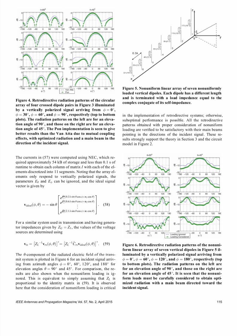
7232019 Unifying the Theory of Mutual Coupling Compensation in Antenna Arrays
httpslidepdfcomreaderfullunifying-the-theory-of-mutual-coupling-compensation-in-antenna-arrays 1219
The currents in (57) were computed using NEC which re-
quired approximately 54 kB of storage and less than 01 s of
runtime to obtain each column of matrix I with each of the el-
ements discretized into 11 segments Noting that the array el-
ements only respond to vertically polarized signals the parameters E and E can be ignored and the ideal signal
vector is given by
videal eth THORN frac14 sin
e j2 eth03 sin costhornz1 cos THORN
e j2
eth06 sin costhornz2 cos THORN
e j2
eth21 sin costhornz7 cos THORN
2664
3775 (58)
For a similar system used in transmission and having genera-
tor impedances given by Z G frac14 Z L the values of the voltage
sources are determined using
vtx frac14 Z L1vrxeth THORN
frac14 Z L
1~C rxvideal eth THORN
(59)
The -component of the radiated electric 1047297eld of the trans-
mit system is plotted in Figure 6 for an incident signal arriv-
ing from azimuth angles frac14 0 60 120 and 180 for
elevation angles frac14 90 and 45 For comparison the re-
sults are also shown when the nonuniform loading is ig-
nored This is equivalent to simply assuming that Z L is
proportional to the identity matrix in (59) It is observed
here that the consideration of nonuniform loading is critical
in the implementation of retrodirective systems otherwise
suboptimal performance is possible All the retrodirective
patterns obtained with proper consideration of nonuniform
loading are veri1047297ed to be satisfactory with their main beams
pointing in the directions of the incident signal These re-
sults strongly support the theory in Section 3 and the circuit
model in Figure 2
Figure 5 Nonuniform linear array of seven nonuniformly
loaded vertical dipoles Each dipole has a different length
and is terminated with a load impedance equal to the
complex conjugate of its self-impedance
Figure 6 Retrodirective radiation patterns of the nonuni-
form linear array of seven vertical dipoles in Figure 5 il-
luminated by a vertically polarized signal arriving from
frac14 0 frac14 60 frac14 120 and frac14 180 respectively (top
to bottom plots) The radiation patterns on the left are
for an elevation angle of 90 and those on the right are
for an elevation angle of 45 It is seen that the nonuni-
form loads must be carefully considered to obtain opti-
mized radiation with a main beam directed toward the
incident signal
Figure 4 Retrodirective radiation patterns of the circular
array of four crossed dipole pairs in Figure 3 illuminated
by a vertically polarized signal arriving from frac14 0
frac14 30 frac14 60 and frac14 90 respectively (top to bottom
plots) The radiation patterns on the left are for an eleva-
tion angle of 90 and those on the right are for an eleva-
tion angle of 45 The Pon implementation is seen to give
better results than the Van Atta due to mutual coupling
effects with optimized radiation and a main beam in the
direction of the incident signal
IEEE Antennas and Propagation Magazine Vol 57 No 2 April 2015 115
7232019 Unifying the Theory of Mutual Coupling Compensation in Antenna Arrays
httpslidepdfcomreaderfullunifying-the-theory-of-mutual-coupling-compensation-in-antenna-arrays 1319
52 ReceiveTransmit Beamforming
Beamforming is a popular application in receive an-
tenna systems for maximizing the reception of a desired sig-
nal while minimizing interference To perform beamforming
in transmission the directions and polarizations of distant re-
ceive systems must be known The reciprocity relationships
in Section 3 give us the con1047297dence to use received quantities
for transmission This is studied in this section where trans-
mit systems are calibrated using coupling matrices and sig-
nals processed in reception
521 Polarization Diverse Systems
The circular array of four crossed dipole pairs illus-
trated in Figure 3 is 1047297rst considered In accordance with the
theory in Section 3 since all the elements are terminated in
equal loads the receive coupling matrix estimate ~C rx de-
rived in Section 51 can also be used here to compensate
mutual coupling in transmission Unlike the retrodirective
system in Section 51 where coupling matrices were only
employed for analysis purposes the reduction of the matrix
size is desirable in a transmit beamformer to minimize the
memory requirement and computations in a practical imple-
mentation Using the hybrid approach introduced in
Section 4 the size of the matrix is further reduced to 8 40 for a total of 320 stored complex coupling parameters in-
stead of 704 This is done by subdividing each of the eight
dipoles into 1047297ve larger segments instead of the 11 used in
the numerical evaluation of ~C rx The column vectors xn yn
and zn in the ideal signal vector of (54) therefore consist of
1047297ve entries
Using the 8 40 matrix ~C obtained by (52) a correla-tion matrix assuming six uncorrelated signals is generated
using
R xx frac14 ~C X6
ifrac141
videal i i E i E i
videal i i E i E i
H
~C
H thorn 2o I N (60)
where ethTHORN H is the conjugate transpose operation i i E i
and E i are the arrival and polarization parameters describing
the ith signal I N is the identity matrix whose dimensions areequal to the number of array elements N frac14 8 and 2o frac14000001 is a 1047297ctitious noise power used for loading the diago-
nal of R xx to ensure a reasonable condition number The noise
is hereby modeled as uncorrelated zero-mean additive white
Gaussian This example considers a scenario involving six
signals at an elevation of frac14 45 Two of these are right-
hand circularly polarized (RHCP) signals arriving from frac140 and 60 two are left-hand circularly polarized (LHCP) sig-
nals arriving from frac14 30 and 30 one is a horizontally
polarized signal arriving from frac14 90 and one is a verti-
cally polarized signal arriving from frac14 120 Radiation is
optimized in the direction of the vertically polarized signal at
frac14 120 and all other signals are considered as interferers
The voltage sources of this system in transmission are then
determined using
vtx frac14 R xx1~C videal eth120 45 1 0THORN
(61)
Using these voltage sources in the numerical model in trans-
mission the radiated electric 1047297eld components E eth THORN and
E eth THORN are computed with NEC The radiation patterns in
transmission at an elevation of frac14 45 for the four different
polarizations of the signals are plotted in Figure 7 These pat-
terns are obtained through the following combinations of the
two orthogonal 1047297eld components
E veth THORN frac14 E eth THORN
E heth THORN frac14 E eth THORN
E RHCP eth THORN frac14 jE eth THORN thorn E eth THORN
E LHCP eth THORN frac14 E eth THORN thorn jE eth THORN (62)
where the subscripts v h RHCP and LHCP stand for verti-
cal horizontal right-hand circular and left-hand circular
polarizations respectively
The results in Figure 7 are very satisfying since nulls
are formed in transmission not only in the directions of the
1047297ve interferers but also with the correct polarizations and
thus con1047297rm that coupling matrices are effective in mutual
coupling compensation of both receive and transmit
Figure 7 Radiation patterns in transmission of the circular
array of four crossed dipole pairs in Figure 3 for receivers
of various polarizations at an elevation of 45 using an 8 40 coupling matrix estimate Radiation is maximized for a
vertically polarized receiver at 120 and minimized for a
horizontally polarized receiver at 90 LHCP receivers at
30 and 30 and RHCP receivers at 0 and 60 Mutual
coupling is compensated effectively with a main beam and
deep nulls forming in these directions
IEEE Antennas and Propagation Magazine Vol 57 No 2 April 2015116
7232019 Unifying the Theory of Mutual Coupling Compensation in Antenna Arrays
httpslidepdfcomreaderfullunifying-the-theory-of-mutual-coupling-compensation-in-antenna-arrays 1419
beamforming systems By reciprocity it is expected that an-
tennas both transmit and receive with the same polarizations
These results suggest that a wireless network can be opti-
mized when signals are transmitted and received using the
same antennas and proper mutual coupling compensation is
implemented Note that if the desired signal waveform is
known and all signals are being transmitted by distant sys-
tems vtx in (61) can also be determined through adaptive
techniques without knowledge of ~C and the desired signalrsquosdirection and polarization The theory presented in this paper
con1047297rms that both deterministic and adaptive approaches can
be effective in the optimization of wireless networks
522 Nonuniformly Loaded Systems
The nonuniform linear array of seven dipoles shown in
Figure 5 is now considered to study the impact of nonuni-
form loading in beamforming The coupling matrix of this
system in reception ~C rx derived in Section 51 is reduced
using the hybrid approach in Section 4 to a 7 35 ~C matrixfor a total of 245 stored complex coupling parameters in-
stead of 539 Although the dipoles are of different lengths a
reduced discretization scheme involving 1047297ve segments per
dipole is nonetheless used in this example The column
vector zn in the ideal signal vector of (58) therefore contains
1047297ve entries instead of the 11 entries used with the original
matrix
Using the 7 35 matrix ~C obtained by (52) and the
same six-signal scenario as in Section 521 the correlation
matrix estimated in reception ie R xx can be used to
determine the required voltage sources in transmission How-
ever nonuniform loading must be accounted for as follows
vtx frac14 Z L1 R xx Z L
H 1
h i1
Z L1~C videal eth120 45THORN
frac14 Z L H R xx
1~C videal eth120 45THORN
(63)
where the parameters E and E are ignored due to the pure
vertical polarization of the antenna system The resulting ra-
diation patterns in transmission are presented in Figure 8along with those obtained when nonuniform loading is
ignored It is seen that optimum beamforming is achieved
since the main beam is in the direction of the desired signal
while deep nulls form in the directions of the interferers As
already observed in Section 51 the main beam of the radia-
tion pattern is adversely affected when nonuniform loading is
ignored in a system where load impedances signi1047297cantly
vary It is seen that interference nulling would also signi1047297-
cantly suffer by the improper compensation of this transmit
system with attenuation of no more than 12 dB in the direc-
tions of the interferers
53 DOAPolarization Estimation
In some applications it is necessary to estimate the
DOA and polarization of incident signals Accurate mutual
coupling compensation is critical in such applications since it
directly affects the accuracy and resolution of the estimator
The eight-dipole array in front of a rectangular conducting
plate similar to that in [80] is considered here This antenna
system is illustrated in Figure 9 For 2-D operation the cou-
pling matrix is estimated as indicated in the 1047297gure The left
part of the matrix is associated with the dipoles and uses row
vectors cij whereas the rectangular conducting plate is subdi-
vided along the horizontal and vertical axes to account for
the variable horizontal and vertical phase shifts of incident
Figure 8 Radiation patterns in transmission of the non-
uniform linear array of seven vertical dipoles in Figure 5
for receivers at an elevation of 45 using a 7 35 cou-
pling matrix estimate Radiation needs to be maximized
at 120 and minimized at 60 30 0 30 and 60
It is seen that the nonuniform loads must be carefullyconsidered to obtain optimized radiation with properly
directed main beam and deep nulls
Figure 9 Geometry of the eight-dipole array in front of a
conducting plate for 2-D operation Eight row vectors as-
sociated with the dipoles 1047297ll the left part of the coupling
matrix for each of its rows whereas the other columns
are associated with the different portions of the plate
IEEE Antennas and Propagation Magazine Vol 57 No 2 April 2015 117
7232019 Unifying the Theory of Mutual Coupling Compensation in Antenna Arrays
httpslidepdfcomreaderfullunifying-the-theory-of-mutual-coupling-compensation-in-antenna-arrays 1519
signals Due to the 1047297nite dimensions of the conducting plate
the polarizations of the array elements may have horizontal
components and both horizontally and vertically oriented in-
cident 1047297elds have to be accounted for on the plate using the
complex scalar parameters C yij and C z
ij respectively
This antenna system is modeled with FEKO [99] using
the method of moments The dipoles are modeled by thin
wires having a length of 612 cm spaced 49 cm apart and
centrally terminated into 50- load impedances The rectan-
gular plate is modeled by a thin 3916-cm-wide and 24-cm-high perfectly conducting surface located 3 cm behind the
dipoles The numerical calculations are performed for an op-
erating frequency of 245 GHz Reordering the entries of the
right part of the matrix for mathematical conciseness the
coupling matrix estimate is obtained by the equations in
Table 1 with the current matrix having the following form
I frac14
z frac12 I wires
s J z J y
24 35frac14
z
I11 I18
I81 I88
24
35
s
J z 91 J z 98
J zK 1 J zK 8
J y91 J y98
J yK 1 J yK 8
2666666437777775
26666666666664
37777777777775
(64)
where z and s are the dipole segment length and conduct-
ing plate patch area respectively I ij is a column vector con-
taining the electric currents on the segments of element i due
to the excitation of element j and J yij and J zij are the y- and
z -directed electric current densities on patch i of the conduct-
ing plate due to the excitation of element j The ideal signal
vector of this problem takes the following form
videal eth E E THORN
frac14
E sin
e j 2 sin ethx1 cos thorny1 sin THORNthornz1 cos frac12
e j 2
sin ethx8 cos thorny8 sin THORNthornz8 cos frac12
e j 2 eth y9 sin sin thorn z 9 cos THORN
e j 2
eth y K sin sin thorn z K cos THORN
266666664
377777775
eth E cos sin thorn E cos THORN
e j2
eth y9 sin sin thorn z 9 cos THORN
e j2
eth y K sin sin thorn z K cos THORN
2
64
3
75
26666666666666664
37777777777777775
(65)
where x j y j and z j are column vectors containing the x y
and z physical locations of the wire segments for j 8 and
y j and z j are scalar values of the y and z locations of the con-
ducting plate patches for j 9 Note that this formulation
assumes that the conducting plate is located at x frac14 0 The nu-
merical solution of this problem involved a total of 104 wire
segments and 2923 surface patches which required approxi-
mately 150 MB of storage and 51 s of runtime to obtain each
of the columns of (64) Since two columns are required to
account for both y- and z -directed currents on each patch the
coupling matrix estimate turns out to be an 8 5950 matrix
Using the size-reduction guidelines presented in Section 4
the size of the estimate can be reduced at the expense of
some performance degradation Here the method is imple-
mented by subdividing the wires into 1047297ve segments each for
a total of 40 wire segments instead of 104 and the conduct-
ing plate into 70 patches 10 wide by 7 high instead of
2923 The size of the coupling matrix estimate then reduces
to 8 180 for a total of 1440 stored complex coupling pa-
rameters instead of 47 600 This is done by computing thesteering vectors for both vertically and horizontally polarized
signals arriving from 85 85 and 25 1725
with angular increments of 10 These two sets of steering
vectors are obtained by substituting videal eth 1 0THORN and
videal eth 0 1THORN as the columns of the matrix V ideal 0 in (52) for
324 different combinations of and Since two polariza-
tions are considered the total number of calibration points is
648 The matrix V ideal in (52) is then a 180 648 matrix con-
taining the ideal signal vectors for the reduced discretization
scheme and the 648 calibration points
The popular MUltiple SIgnal Classi1047297cation (MUSIC)algorithm described in [100 ndash 102] is employed here to per-
form DOA estimation in a polarization diverse scenario By
the theory of this paper the MUSIC DOA spectrum can be
expressed as
P eth THORN frac14 1
min eth A H ATHORN1 A H E N E N
H Ah i (66)
where
A frac14 ~C videal eth 1 0THORN videal eth 0 1THORNfrac12 (67)
minfrac12 is the smallest eigenvalue of the matrix inside the
brackets and E N is the matrix containing the noise eigen-
vectors obtained through the eigendecomposition of the cor-
relation matrix A signal scenario involving two plane waves
arriving from eth THORNfrac14eth30 60THORN and eth THORN frac14 eth0 45THORN re-
spectively is considered In addition the two signals are
circularly polarized The 1047297rst signal is RHCP ie eth E E THORN frac14eth j 1THORN whereas the second signal is LHCP ie eth E E THORN frac14eth1 j THORN The eigenvalue decomposition of the correlation matrix
provides six noise eigenvectors which are associated with
the six smallest eigenvalues to 1047297ll the matrix E N in (66) The
2-D DOA spectra are presented in Figure 10
For comparison the DOA spectra obtained without
compensation with a square coupling matrix having dimen-
sions 8 8 and with the full 8 5950 matrix are also
shown The accuracies and resolutions obtained with the
larger matrices in Figure 10c and d are seen to be signi1047297-
cantly better The reduced 8 180 matrix is seen to be a
very reasonable compromise with a slight performance degra-
dation but a reduction of approximately 97 of the memory
requirement and computations required for the evaluation of
the DOA spectra
IEEE Antennas and Propagation Magazine Vol 57 No 2 April 2015118
7232019 Unifying the Theory of Mutual Coupling Compensation in Antenna Arrays
httpslidepdfcomreaderfullunifying-the-theory-of-mutual-coupling-compensation-in-antenna-arrays 1619
It is important to note here that the 8 180 ~C matrixcan also be determined with measurements using (51) where
the matrix V is 1047297lled with measured steering vectors In the
case studied in this section 648 measured steering vectors
are necessary to obtain ~C This is a substantial reduction
compared with the number of measurements required for 2-D
operation using conventional means More details on this are
available in [89]
6 Conclusion
This paper has thoroughly reviewed the limitations of current mutual coupling compensation methods Through the
derivation of clear theoretical foundations that apply to both
receive and transmit systems the theory of mutual coupling
compensation was uni1047297ed to provide ef 1047297cient mutual coupling
compensation methods that can be employed with systems of
arbitrary geometries Reciprocity relationships were clearly
derived based on the receive and transmit formulations
thereby allowing the use of receive-mode compensation data
for both reception and transmission if the reciprocity relation-
ships are employed properly Both theoretical and experimen-
tal techniques can be used to evaluate mutual coupling by the
presented theory This theory can be veri1047297ed in a straight-forward fashion using proven electromagnetic codes and the
examples given in this paper on retrodirective systems beam-
formers and DOA estimation can be followed by the reader
for validation Finally this theory will likely 1047297nd several other
applications than those presented and contributes to the areas
of antenna theory mutual coupling analysis complex struc-
ture modeling and antenna measurements
7 AppendixDerivation of Analytical
Formulations in Table 1
The analytical formulations presented in Table 1 are
better understood using the various equivalent circuits of an-
tenna systems shown in Figure 11 In receive-mode the
open-circuit voltages are given by
voc A frac14 Z ANT I T videal (68)
voc L frac14 ethZ L thorn Z THORN I T
L videal (69)
voc frac14 ZI T scvideal (70)
Figure 10 2-D DOA estimation using the eight-dipole linear array in front of a rectangular con-
ducting plate for two circularly polarized signals from eth THORN frac14 eth30 60THORN and eth0 45THORN using
MUSIC Mutual coupling compensation implemented with an 8 180 coupling matrix estimate is
seen to give very satisfying performance and ef 1047297ciency with sharp peaks toward the two signals
IEEE Antennas and Propagation Magazine Vol 57 No 2 April 2015 119
7232019 Unifying the Theory of Mutual Coupling Compensation in Antenna Arrays
httpslidepdfcomreaderfullunifying-the-theory-of-mutual-coupling-compensation-in-antenna-arrays 1719
This is consistent with classic antenna theory presented in
[6] The port voltages should be equal irrespective of the
method By circuit theory these are given by
vrx frac14 Z LethZ L thorn Z ANT THORN1
voc A (71)
frac14 Z LethZ L thorn Z THORN1voc L
(72)
frac14 Z LethZ L thorn Z THORN1voc (73)
Substituting (68) ndash (70) into (71) ndash (73) and performing some
matrix manipulations gives
vrx frac14 Z LethZ L thorn Z ANT THORN1
Z ANT I T videal (74)
frac14 Z L I T L videal (75)
frac14 Z LethZ L thorn Z THORN1ZI T
scvideal (76)
The admittance formulations are obtained by substituting
Z L frac14 Y L1 Z ANT frac14 Y ANT
1 and Z frac14 Y 1 into (74) ndash (76) For
example (76) gives
vrx frac14 Y 1 L Y 1
L thorn Y 1 1
Y 1 I T scvideal
frac14 Y 1 L Y LethY L thorn Y THORN1
YY 1 I T scvideal
frac14 ethY L thorn Y THORN1 I T
scvideal (77)
In transmit-mode the radiated 1047297elds are scaled by v A v L
and v which are obtained by voltage division in 1) and 3)
In 2) v L is simply equal to vtx The admittance formulations
in transmit-mode are obtained in the same fashion as the ex-
ample of (77)
8 References
[1] H S Lui H T Hui and M S Leong ldquoA note on the mutualcoupling problems in transmitting and receiving antenna arraysrdquo IEEE Antennas Propag Mag vol 51 no 5 pp 171 ndash 176 Oct 2009
[2] C A Balanis Antenna Theory Analysis and Design 2nd ed NewYork NY USA Wiley 1997
[3] R C Hansen Phased Array Antennas New York NY USA Wiley1998
[4] T A Milligan Modern Antenna Design 2nd ed New York NYUSA Wiley 2005
[5] R J Mailloux Phased Array Antenna Handbook 2nd ed BostonMA USA Artech House 2005[6] S A Schelkunoff and H T Friis Antennas Theory and Practice
New York NY USA Wiley 1952[7] R P Meys ldquoA summary of the transmitting and receiving properties
of antennasrdquo IEEE Antennas Propag Mag vol 42 no 3 pp 49 ndash 53Jun 2000
[8] S Henault ldquoEvaluation of electromagnetic coupling in antenna sys-tems A uni1047297ed theory and its applicationsrdquo PhD dissertation DeptElect Comput Eng Royal Military College of Canada KingstonON Canada Jan 2012
[9] S Henault Y M M Antar S Rajan R Inkol and S Wang ldquoThemultiple antenna induced EMF method for the precise calculation of thecoupling matrix in a receiving antenna arrayrdquo Progr Electromagn Res M vol 8 pp 103 ndash 118 2009
[10] P S Carter ldquoCircuit relations in radiating systems and applications toantenna problemsrdquo Proc IRE vol 20 no 6 pp 1004 ndash 1041 Jun 1932
[11] H E King ldquoMutual impedance of unequal length antennas in echelonrdquo IRE Trans Antennas Propag vol AP-5 no 3 pp 306 ndash 313 Jul 1957
[12] J H Richmond and N H Geary ldquoMutual impedance of nonplanar-skew sinusoidal dipolesrdquo IEEE Trans Antennas Propag vol AP-23no 3 pp 412 ndash 414 May 1975
[13] J D Kraus Antennas 2nd ed New York NY USA McGraw-Hill1988
[14] S A Mitilineos C A Papagianni G I Verikaki and C N CapsalisldquoDesign of switched beam planar arrays using the method of geneticalgorithmsrdquo Progr Electromagn Res vol 46 pp 105 ndash 126 2004
[15] A W Love ldquoComment On the equivalent circuit of a receiving antennardquo IEEE Antennas Propag Mag vol 44 no 5 pp 124 ndash 125 Oct 2002
[16] J B Andersen and R G Vaughan ldquoTransmitting receiving and scat-tering properties of antennasrdquo IEEE Antennas Propag Mag vol 45no 4 pp 93 ndash 98 Aug 2003
[17] J Van Bladel ldquoOn the equivalent circuit of a receiving antennardquo
IEEE Antennas Propag Mag vol 44 no 1 pp 164 ndash
165 Feb 2002[18] R E Collin ldquoLimitations on the Thevenin and Norton equivalent cir-cuits for a receiving antennardquo IEEE Antennas Propag Mag vol 45no 2 pp 119 ndash 124 Apr 2003
[19] C T Tai ldquoA Critical study of the circuit relations of two distant an-tennasrdquo IEEE Antennas Propag Mag vol 44 no 6 pp 32 ndash 37Dec 2002
[20] C T Tai ldquoCorrection V A critical study of the circuit relations of twodistant antennasrdquo IEEE Antennas Propag Mag vol 45 no 1 p 125Feb 2003
[21] A W Love ldquoCorrection V A critical study of the circuit relations of twodistant antennasrdquo IEEE Antennas Propag Mag vol 45 no 2 p 42Apr 2003
[22] C G Montgomery R H Dicke and E M Purcell Principles of Microwave Circuits New York NY USA McGraw-Hill 1948
[23] S Ramo and J Whinnery Fields and Waves in Modern Radio 2nd ed New York NY USA Wiley 1953
[24] S Silver Microwave Antenna Theory and Design New York NYUSA McGraw-Hill 1949
[25] R C Hansen ldquoRelationships between antennas as scatterers and asradiatorsrdquo Proc IEEE vol 77 no 5 pp 659 ndash 662 May 1989
[26] C C Su ldquoOn the equivalent generator voltage and generator internalimpedance for receiving antennasrdquo IEEE Trans Antennas Propagvol 51 no 2 pp 279 ndash 285 Feb 2003
[27] S R Best and B C Kaanta ldquoA tutorial on the receiving and scattering properties of antennasrdquo IEEE Antennas Propag Mag vol 51 no 5 pp 26 ndash 37 Oct 2009
[28] J W Wallace and R Mehmood ldquoOn the accuracy of equivalent circuit models for multi-antenna systemsrdquo IEEE Trans Antennas Propagvol 60 no 2 pp 540 ndash 547 Feb 2012
[29] D M Pozar ldquoThe active element patternrdquo IEEE Trans Antennas Pro- pag vol 42 no 8 pp 1176 ndash 1178 Aug 1994
Figure 11 Equivalent circuits of (left) transmit and (right)
receive antenna systems for the three different loading con-
ditions given in Table 1 These equivalent circuits use vec-
tors and matrices to represent voltages and impedances
IEEE Antennas and Propagation Magazine Vol 57 No 2 April 2015120
7232019 Unifying the Theory of Mutual Coupling Compensation in Antenna Arrays
httpslidepdfcomreaderfullunifying-the-theory-of-mutual-coupling-compensation-in-antenna-arrays 1819
[30] D F Kelley and W L Stutzman ldquoArray antenna pattern modelingmethods that include mutual coupling effectsrdquo IEEE Trans Antennas Propag vol 41 no 12 pp 1625 ndash 1632 Dec 1993
[31] K Takamizawa ldquoAnalysis of highly coupled wideband antenna arraysusing scattering parameter network modelsrdquo PhD dissertation DeptElect Comput Eng Virginia Polytech Inst State Univ BlacksburgVA USA Dec 2002
[32] D M Pozar ldquoA relation between the active input impedance and theactive element pattern of a phased arrayrdquo IEEE Trans Antennas Propag vol 51 no 9 pp 2486 ndash 2489 Sep 2003
[33] D F Kelley ldquoRelationships between active element patterns and mutual impedance matrices in phased array antennasrdquo in Proc IEEE Int Symp Antennas Propag 2002 pp 524 ndash 527
[34] D F Kelley ldquo
Embedded element patterns and mutual impedancematrices in the terminated phased array environmentrdquo in Proc IEEE Int Symp Antennas Propag 2005 pp 659 ndash 662
[35] R F Harrington ldquoAntenna excitation for maximum gainrdquo IEEE Trans Antennas Propag vol AP-13 no 6 pp 896 ndash 903 Nov 1965
[36] H Rogier and E Bonek ldquoAnalytical spherical-mode-based compensa-tion of mutual coupling in uniform circular arrays for direction-of-arrivalestimationrdquo Int J Electron Commun vol 60 no 3 pp 179 ndash 189Mar 2006
[37] A T De Hoop ldquoThe N-port receiving antenna and its equivalent elec-trical networkrdquo Philips Res Rep vol 30 pp 302 ndash 315 1975
[38] P S Kildal ldquoEquivalent circuits of receive antennas in signal process-ing arraysrdquo Microw Opt Technol Lett vol 21 no 4 pp 244 ndash 246May 1999
[39] K F Warnick B Woestenburg L Belostotski and P Russer ldquoMinimiz-ing the noise penalty due to mutual coupling for a receiving arrayrdquo IEEE Trans Antennas Propag vol 57 no 6 pp 1634 ndash 1644 Jun 2009
[40] R O Schmidt ldquoMultilinear array manifold interpolationrdquo IEEE TransSignal Process vol 40 no 4 pp 857 ndash 866 Apr 1992
[41] A J Weiss and B Friedlander ldquoManifold interpolation for diversely po-larized arraysrdquo Proc Inst Elect Eng V Radar Sonar Navig vol 141no 1 pp 19 ndash 24 Feb 1994
[42] R J Allard and D H Werner ldquoThe model-based parameter estimationof antenna radiation patterns using windowed interpolation and sphericalharmonicsrdquo IEEE Trans Antennas Propag vol 51 no 8 pp 1891 ndash 1906 Aug 2003
[43] M Landmann and G Del Galdo ldquoEf 1047297cient antenna description for MIMO channel modelling and estimationrdquo in Proc 7th Eur ConfWireless Technol Amsterdam The Netherlands 2004 pp 217 ndash 220
[44] G Del Galdo J Lotze M Landmann and M Haardt ldquoModelling and manipulation of polarimetric antenna beam patterns via sphericalharmonicsrdquo in Proc 14th Eur Signal Process Conf Florence ItalySep 2006 pp 1 ndash 5
[45] F Belloni A Richter and V Koivunen ldquo
DoA estimation via manifold separation for arbitrary array structuresrdquo IEEE Trans Signal Processvol 55 no 10 pp 4800 ndash 4810 Oct 2007
[46] H T Hui ldquoDecoupling methods for the mutual coupling effect in an-tenna arrays A reviewrdquo Recent Patents Eng vol 1 no 2 pp 187 ndash 193 Jun 2007
[47] T Su and H Ling ldquoOn modeling mutual coupling in antenna arraysusing the coupling matrixrdquo Microw Opt Technol Lett vol 28 no 4 pp 231 ndash 237 Feb 2001
[48] P Darwood P N Fletcher and G S Hilton ldquoMutual couplingcompensation in small planar array antennasrdquo Proc Inst Elect Eng V
Microw Antennas Propag vol 145 no 1 pp 1 ndash 6 Feb 1998[49] H Steyskal and J S Herd ldquoMutual coupling compensation in small array
antennasrdquo IEEE Trans Antennas Propag vol 38 no 12 pp 1971 ndash 1975 Dec 1990
[50] I J Gupta and A A Ksienski ldquoEffect of mutual coupling on the performance of adaptive arraysrdquo IEEE Trans Antennas Propag
vol AP-31 no 5 pp 785 ndash 791 Sep 1983[51] C C Yeh M L Leou and D R Ucci ldquoBearing estimations with mu-
tual coupling presentrdquo IEEE Trans Antennas Propag vol 37 no 10 pp 1332 ndash 1335 Oct 1989
[52] C Roller and W Wasylkiwskyj ldquoEffects of mutual coupling on super-resolution DF in linear arraysrdquo in Proc IEEE Int Conf AcoustSpeech Signal Process vol 5 1992 pp 257 ndash 260
[53] Z Huang C A Balanis and C R Birtcher ldquoMutual couplingcompensation in UCAs Simulations and experimentrdquo IEEE Trans Antennas Propag vol 54 no 11 pp 3082 ndash 3086 Nov 2006
[54] K C Lee and T H Chu ldquoA circuit model for mutual couplinganalysis of a 1047297nite antenna arrayrdquo IEEE Trans Electromagn Compatvol 38 no 3 pp 483 ndash 489 Aug 1996
[55] K W Lo and T B Vu ldquoSimple S-parameter model for receiving an-tenna arrayrdquo Electron Lett vol 24 no 20 pp 1264 ndash 1266 Sep 1988
[56] K M Pasala and E M Friel ldquoMutual coupling effects and their reduction in wideband direction of arrival estimationrdquo IEEE Trans Aerosp Electron Syst vol 30 no 4 pp 1116 ndash 1122 Apr 1994
[57] R S Adve and T K Sarkar ldquoCompensation for the effects of mutualcoupling on direct data domain adaptive algorithmsrdquo IEEE Trans An-tennas Propag vol 48 no 1 pp 86 ndash 94 Jan 2000
[58] R F Harrington Field Computation by Moment Methods New York NY USA Wiley 1968
[59] J Pierre and M Kaveh ldquoExperimental performance of calibration and direction-1047297nding algorithmsrdquo in Proc IEEE Int Conf Acoust SpeechSignal Process vol 2 Toronto ON Canada Apr 1991 pp 1365 ndash 1368
[60] T Su K Dandekar and H Ling ldquoSimulation of mutual couplingeffect in circular arrays for direction-1047297nding applicationsrdquo Microw
Opt Technol Lett vol 26 no 5 pp 331 ndash
336 Sep 2000[61] K R Dandekar H Ling and G Xu ldquoExperimental study of mutualcoupling compensation in smart antenna applicationsrdquo IEEE TransWireless Commun vol 1 no 3 pp 480 ndash 487 Jul 2002
[62] H T Hui ldquoReducing the mutual coupling effect in adaptive nullingusing a re-de1047297ned mutual impedancerdquo IEEE Microw Wireless Compon Lett vol 12 no 5 pp 178 ndash 180 May 2002
[63] H T Hui ldquoCompensating for the mutual coupling effect in direction1047297nding based on a new calculation method for mutual impedancerdquo IEEE Antennas Wireless Propag Lett vol 2 no 1 pp 26 ndash 29 2003
[64] H T Hui ldquoImproved compensation for the mutual coupling effect ina dipole array for direction 1047297ndingrdquo IEEE Trans Antennas Propagvol 51 no 9 pp 2498 ndash 2503 Sep 2003
[65] H T Hui ldquoA practical approach to compensate for the mutual couplingeffect in an adaptive dipole arrayrdquo IEEE Trans Antennas Propagvol 52 no 5 pp 1262 ndash 1269 May 2004
[66] H T Hui ldquoA new de1047297nition of mutual impedance for application in di-
pole receiving antenna arraysrdquo IEEE Antennas Wireless Propag Lettvol 3 no 1 pp 364 ndash 367 Dec 2004
[67] S Henault and Y M M Antar ldquoWideband analysis of mutual couplingcompensation methodsrdquo Int J Antennas Propag vol 2011 2011Art ID 756 153
[68] B Friedlander and A J Weiss ldquoDirection 1047297nding in the presence of mutual couplingrdquo IEEE Trans Antennas Propag vol 39 no 3 pp 273 ndash 284 Mar 1991
[69] E K L Hung ldquoA critical study of a self-calibrating direction-1047297ndingmethod for arraysrdquo IEEE Trans Signal Process vol 42 no 2 pp 471 ndash 474 Feb 1994
[70] F S Sellone and A Serra ldquoA novel online mutual coupling compen-sation algorithm for uniform and linear arraysrdquo IEEE Trans Signal Process vol 55 no 2 pp 560 ndash 573 Feb 2007
[71] M Lin and L Yang ldquoBlind calibration and DOA estimation with uni-form circular arrays in the presence of mutual couplingrdquo IEEE Anten-
nas Wireless Propag Lett vol 5 no 1 pp 315 ndash
318 Dec 2006[72] D Y Gao B H Wang and Y Guo ldquoComments on lsquoBlind calibrationand DOA estimation with uniform circular arrays in the presence of mutual couplingrsquordquo IEEE Antennas Wireless Propag Lett vol 5 no 1 pp 566 ndash 568 Dec 2006
[73] M Lin and L Yang ldquoReply to the comments on lsquoBlind calibration and DOA estimation with uniform circular arrays in the presence of mutualcouplingrsquordquo IEEE Antennas Wireless Propag Lett vol 5 no 1 pp 568 ndash 569 Dec 2006
[74] Q Bao C C Ko and W Zhi ldquoDOA estimation under unknownmutual coupling and multipathrdquo IEEE Trans Aerosp Electron Systvol 41 no 2 pp 565 ndash 573 Apr 2005
[75] Z Ye and C Liu ldquoOn the resiliency of MUSIC direction 1047297nding against antenna sensor couplingrdquo IEEE Trans Antennas Propag vol 56no 2 pp 371 ndash 380 Feb 2008
[76] Z Ye and C Liu ldquo2-D DOA estimation in the presence of mutualcouplingrdquo IEEE Trans Antennas Propag vol 56 no 10 pp 3150 ndash
3158 Oct 2008[77] Y Zhang Q Wan and A M Huang ldquoLocalization of narrow band
sources in the presence of mutual coupling via sparse solution 1047297ndingrdquo Progr Electromagn Res vol 86 pp 243 ndash 257 2008
[78] T Svantesson ldquoAntennas and propagation from a signal processing perspectiverdquo PhD dissertation Dept Signals Syst Chalmers UnivTechnol Goumlteborg Sweden 2001
[79] S Henault and Y M M Antar ldquoLimitations of online calibrationmethodsrdquo in Proc IEEE Int Symp Antennas Propag Toronto ONCanada Jul 2010 pp 1 ndash 4
[80] I J Gupta et al ldquoAn experimental study of antenna array calibrationrdquo IEEE Trans Antennas Propag vol 51 no 3 pp 664 ndash 667 Mar 2003
[81] C K E Lau R S Adve and T K Sarkar ldquoMinimum norm mutual cou- pling compensation with applications in direction of arrival estimationrdquo IEEE Trans Antennas Propag vol 52 no 8 pp 2034 ndash 2041 Aug 2004
IEEE Antennas and Propagation Magazine Vol 57 No 2 April 2015 121
7232019 Unifying the Theory of Mutual Coupling Compensation in Antenna Arrays
httpslidepdfcomreaderfullunifying-the-theory-of-mutual-coupling-compensation-in-antenna-arrays 1919
[82] Q Y Yuan Q Chen and K Sawaya ldquoAccurate DOA estimation usingarray antenna with arbitrary geometryrdquo IEEE Trans Antennas Propagvol 53 no 4 pp 1352 ndash 1357 Apr 2005
[83] S Henault Y M M Antar S Rajan R Inkol and S Wang ldquoEffectsof mutual coupling on the accuracy of adcock direction 1047297nding systemsrdquo IEEE Trans Aerosp Electron Syst vol 48 no 4 pp 2990 ndash 3005Oct 2012
[84] T Su and H Ling ldquoOn the simultaneous modeling of array mutualcoupling and array-platform interactionsrdquo Microw Opt Technol Lettvol 33 no 3 pp 167 ndash 171 May 2002
[85] A Ferreol E Boyer P Larzabal and M Haardt ldquoOn the introductionof an extended coupling matrix for a 2D bearing estimation with an ex- perimental RF systemrdquo Signal Process vol 87 no 9 pp 2005 ndash 2016
Sep 2007[86] J B Andersen and H H Rasmussen ldquoDecoupling and descatteringnetworks for antennasrdquo IEEE Trans Antennas Propag vol AP-24no 6 pp 841 ndash 846 Nov 1976
[87] M Kragalott M S Kluskens D A Zolnick W M Dorsey and J A Valenzi ldquoA toolset independent hybrid method for calculatingantenna couplingrdquo IEEE Trans Antennas Propag vol 59 no 2 pp 443 ndash 451 Feb 2011
[88] A E H Love ldquoThe integration of equations of propagation of electricwavesrdquo Philos Trans Roy Soc London A Math Phys Sci vol 197 pp 1 ndash 45 1901
[89] S Henault S K Podilchak S M Mikki and Y M M Antar ldquoA meth-odology for mutual coupling estimation and compensation in antennasrdquo IEEE Trans Antennas Propag vol 61 no 3 pp 1119 ndash 1131Mar 2013
[90] S Henault and Y M M Antar ldquoOn the interpolation of radiation pat-terns in the calibration of antenna arraysrdquo in IEEE Int Symp Antennas
Propag Spokane WA USA Jul 2011 pp 1747 ndash 1750[91] S Henault and Y M M Antar ldquoA hybrid approach for antenna array
calibrationrdquo in Proc IEEE Int Symp Antennas Propag SpokaneWA USA Jul 2011 pp 1751 ndash 1754
[92] C Pon ldquoRetrodirective array using the heterodyne techniquerdquo IEEE Trans Antennas Propag vol 12 no 2 pp 176 ndash 180 Mar 1964
[93] A F Kay ldquoComments on self-phasing array antennas and electronicallyadaptive antenna systemsrdquo IEEE Trans Antennas Propag vol AP-12no 6 pp 792 ndash 793 Nov 1964
[94] V F Fusco ldquoResponse of retrodirective array in the presence of multi- ple spatially separated sourcesrdquo IEEE Trans Antennas Propag vol 54no 4 pp 1352 ndash 1354 Apr 2006
[95] NEC-2 Manual Lawrence Livermore National Laboratory LivermoreCA USA 1996
[96] L C Van Atta ldquoElectromagnetic re1047298ectorrdquo US Patent 2 908 002Oct 6 1959
[97] T Larsen ldquo
Re1047298
ector arraysrdquo
IEEE Trans Antennas Propag vol AP-14no 6 pp 689 ndash 693 Nov 1966[98] J Appel-Hansen ldquoA van Atta re1047298ector consisting of half-wave dipolesrdquo
IEEE Trans Antennas Propag vol AP-14 no 6 pp 694 ndash 700 Nov 1966
[99] FEKO-Comprehensive EM Solutions [Online] Available httpwwwfekoinfo
[100] R O Schmidt ldquoMultiple emitter location and signal parameter estima-tionrdquo IEEE Trans Antennas Propag vol AP-34 no 3 pp 276 ndash 280Mar 1986
[101] R O Schmidt and R Franks ldquoMultiple source DF signal processingAn experimental systemrdquo IEEE Trans Antennas Propag vol AP-34no 3 pp 281 ndash 290 Mar 1986
[102] E R Ferrara and T M Parks ldquoDirection 1047297nding with an array of antennas having diverse polarizationsrdquo IEEE Trans Antennas Propagvol AP-31 no 2 pp 231 ndash 236 Mar 1983
Simon Henault received the BEng degreefrom Laval University Queacutebec City QCCanada in 2001 and the MASc and PhDdegrees from the Royal Military College of Canada Kingston ON Canada in 2008 and 2012 respectively all in electrical engineering
Since 1998 he has been with CanadarsquosDepartment of National Defence in variouscapacities including two years as a facultymember with the Royal Military College of Canada and multiple assignments with De-fence Research and Development CanadaHe has expertise in antenna radio frequency
and signal processing systems employed in a variety of electronic warfarespace communication and unmanned aerial vehicle platforms
Dr Henault is a regular Reviewer for several journals and conferences
Yahia M M Antar (Srsquo73 ndash Mrsquo76 ndash SMrsquo85 ndash LFrsquo00) received the BSc (Hons) degree fromAlexandria University Alexandria Egypt in1966 and the MSc and PhD degrees fromthe University of Manitoba Winnipeg MBCanada in 1971 and 1975 respectively all inelectrical engineering
In 1977 he held a Government of Canada
Visiting Fellowship with the Communica-tions Research Centre Ottawa ON Canadawhere he worked with the Space TechnologyDirectorate on communications antennas for satellite systems In May 1979 he joined the
Division of Electrical Engineering National Research Council of CanadaOttawa where he worked on polarization radar applications in remote sens-ing of precipitation radio wave propagation electromagnetic scatteringand radar cross-section investigations In November 1987 he joined thestaff of the Department of Electrical and Computer Engineering Royal Mil-itary College of Canada Kingston ON where he has held the position of Professor since 1990 and is currently the Vice Dean for defense and secu-rity research He has authored or coauthored about 200 journal papersmany chapters in books and about 400 refereed conference papers holdsseveral patents has chaired several national and international conferencesand has given plenary talks at many conferences He has supervised and cosupervised over 80 PhD and MSc theses at the Royal Military Collegeof Canada and at Queenrsquos University Kingston several of which have re-ceived the Governor General of Canada Gold Medal the outstanding PhDthesis of the Division of Applied Science as well as many Best Paper Awardsin major international symposia He served as the Chairman of the Canadian Nationa l Commis sion for Radio Scienc e (CNC URSI 1999 ndash 2008) and the Commission B National Chair (1993 ndash 1999) and held an adjunct ap- pointme nt at the Univer sity of Manito ba and has a cross appoint ment at Queenrsquos University
Dr Antar is a Fellow of the Engineering Institute of Canada and theElectromagnetic Academy He serves as an Associate Editor for the IEEEA NTENNAS AND PROPAGATION MAGAZINE served as an Associate Editor for the IEEE TRANSACTIONS ON A NTENNAS AND PROPAGATION and theIEEE A NTENNAS AND WIRELESS PROPAGATION LETTERS and was a mem- ber of the Editorial Board of the International Journal of RF and MicrowaveComputer-Aided Engineering He served on Natural Sciences and Engineer-ing Research Council of Canada grant selection and strategic grant commit-
tees on Ontario Early Research Awards panels and on review panels for the National Science Foundation In May 2002 he was awarded a Tier 1Canada Research Chair in Electromagnetic Engineering which has been re-newed in 2009 In 2003 he was awarded the Royal Military College of Canada ldquoExcellence in Researchrdquo Prize and the RMCC Class of 1965Teaching Excellence Award in 2012 He was elected by the Council of theInternational Union of Radio Science to the Board as Vice President in Au-gust 2008 and in 2013 and to the IEEE Antennas and Propagation SocietyAdministration Committee in December 2009 On January 31 2011 he wasappointed Member of the Canadian Defence Science Advisory Board He ison the IEEE Antennas and Propagation Society Distinguished LecturersProgram In October 2012 he received the Queenrsquos Diamond Jubilee Medalfrom the Governor General of Canada in recognition of his contribution toCanada He was a recipient of the 2014 IEEE Canada RA Fessenden Silver Medal and the 2015 IEEE Canada J M Ham Outstanding EngineeringEducation Award
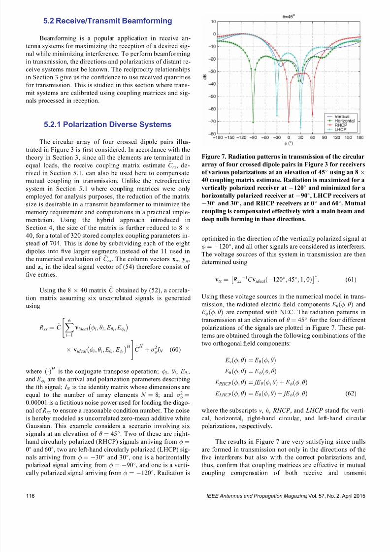
7232019 Unifying the Theory of Mutual Coupling Compensation in Antenna Arrays
httpslidepdfcomreaderfullunifying-the-theory-of-mutual-coupling-compensation-in-antenna-arrays 1319
52 ReceiveTransmit Beamforming
Beamforming is a popular application in receive an-
tenna systems for maximizing the reception of a desired sig-
nal while minimizing interference To perform beamforming
in transmission the directions and polarizations of distant re-
ceive systems must be known The reciprocity relationships
in Section 3 give us the con1047297dence to use received quantities
for transmission This is studied in this section where trans-
mit systems are calibrated using coupling matrices and sig-
nals processed in reception
521 Polarization Diverse Systems
The circular array of four crossed dipole pairs illus-
trated in Figure 3 is 1047297rst considered In accordance with the
theory in Section 3 since all the elements are terminated in
equal loads the receive coupling matrix estimate ~C rx de-
rived in Section 51 can also be used here to compensate
mutual coupling in transmission Unlike the retrodirective
system in Section 51 where coupling matrices were only
employed for analysis purposes the reduction of the matrix
size is desirable in a transmit beamformer to minimize the
memory requirement and computations in a practical imple-
mentation Using the hybrid approach introduced in
Section 4 the size of the matrix is further reduced to 8 40 for a total of 320 stored complex coupling parameters in-
stead of 704 This is done by subdividing each of the eight
dipoles into 1047297ve larger segments instead of the 11 used in
the numerical evaluation of ~C rx The column vectors xn yn
and zn in the ideal signal vector of (54) therefore consist of
1047297ve entries
Using the 8 40 matrix ~C obtained by (52) a correla-tion matrix assuming six uncorrelated signals is generated
using
R xx frac14 ~C X6
ifrac141
videal i i E i E i
videal i i E i E i
H
~C
H thorn 2o I N (60)
where ethTHORN H is the conjugate transpose operation i i E i
and E i are the arrival and polarization parameters describing
the ith signal I N is the identity matrix whose dimensions areequal to the number of array elements N frac14 8 and 2o frac14000001 is a 1047297ctitious noise power used for loading the diago-
nal of R xx to ensure a reasonable condition number The noise
is hereby modeled as uncorrelated zero-mean additive white
Gaussian This example considers a scenario involving six
signals at an elevation of frac14 45 Two of these are right-
hand circularly polarized (RHCP) signals arriving from frac140 and 60 two are left-hand circularly polarized (LHCP) sig-
nals arriving from frac14 30 and 30 one is a horizontally
polarized signal arriving from frac14 90 and one is a verti-
cally polarized signal arriving from frac14 120 Radiation is
optimized in the direction of the vertically polarized signal at
frac14 120 and all other signals are considered as interferers
The voltage sources of this system in transmission are then
determined using
vtx frac14 R xx1~C videal eth120 45 1 0THORN
(61)
Using these voltage sources in the numerical model in trans-
mission the radiated electric 1047297eld components E eth THORN and
E eth THORN are computed with NEC The radiation patterns in
transmission at an elevation of frac14 45 for the four different
polarizations of the signals are plotted in Figure 7 These pat-
terns are obtained through the following combinations of the
two orthogonal 1047297eld components
E veth THORN frac14 E eth THORN
E heth THORN frac14 E eth THORN
E RHCP eth THORN frac14 jE eth THORN thorn E eth THORN
E LHCP eth THORN frac14 E eth THORN thorn jE eth THORN (62)
where the subscripts v h RHCP and LHCP stand for verti-
cal horizontal right-hand circular and left-hand circular
polarizations respectively
The results in Figure 7 are very satisfying since nulls
are formed in transmission not only in the directions of the
1047297ve interferers but also with the correct polarizations and
thus con1047297rm that coupling matrices are effective in mutual
coupling compensation of both receive and transmit
Figure 7 Radiation patterns in transmission of the circular
array of four crossed dipole pairs in Figure 3 for receivers
of various polarizations at an elevation of 45 using an 8 40 coupling matrix estimate Radiation is maximized for a
vertically polarized receiver at 120 and minimized for a
horizontally polarized receiver at 90 LHCP receivers at
30 and 30 and RHCP receivers at 0 and 60 Mutual
coupling is compensated effectively with a main beam and
deep nulls forming in these directions
IEEE Antennas and Propagation Magazine Vol 57 No 2 April 2015116
7232019 Unifying the Theory of Mutual Coupling Compensation in Antenna Arrays
httpslidepdfcomreaderfullunifying-the-theory-of-mutual-coupling-compensation-in-antenna-arrays 1419
beamforming systems By reciprocity it is expected that an-
tennas both transmit and receive with the same polarizations
These results suggest that a wireless network can be opti-
mized when signals are transmitted and received using the
same antennas and proper mutual coupling compensation is
implemented Note that if the desired signal waveform is
known and all signals are being transmitted by distant sys-
tems vtx in (61) can also be determined through adaptive
techniques without knowledge of ~C and the desired signalrsquosdirection and polarization The theory presented in this paper
con1047297rms that both deterministic and adaptive approaches can
be effective in the optimization of wireless networks
522 Nonuniformly Loaded Systems
The nonuniform linear array of seven dipoles shown in
Figure 5 is now considered to study the impact of nonuni-
form loading in beamforming The coupling matrix of this
system in reception ~C rx derived in Section 51 is reduced
using the hybrid approach in Section 4 to a 7 35 ~C matrixfor a total of 245 stored complex coupling parameters in-
stead of 539 Although the dipoles are of different lengths a
reduced discretization scheme involving 1047297ve segments per
dipole is nonetheless used in this example The column
vector zn in the ideal signal vector of (58) therefore contains
1047297ve entries instead of the 11 entries used with the original
matrix
Using the 7 35 matrix ~C obtained by (52) and the
same six-signal scenario as in Section 521 the correlation
matrix estimated in reception ie R xx can be used to
determine the required voltage sources in transmission How-
ever nonuniform loading must be accounted for as follows
vtx frac14 Z L1 R xx Z L
H 1
h i1
Z L1~C videal eth120 45THORN
frac14 Z L H R xx
1~C videal eth120 45THORN
(63)
where the parameters E and E are ignored due to the pure
vertical polarization of the antenna system The resulting ra-
diation patterns in transmission are presented in Figure 8along with those obtained when nonuniform loading is
ignored It is seen that optimum beamforming is achieved
since the main beam is in the direction of the desired signal
while deep nulls form in the directions of the interferers As
already observed in Section 51 the main beam of the radia-
tion pattern is adversely affected when nonuniform loading is
ignored in a system where load impedances signi1047297cantly
vary It is seen that interference nulling would also signi1047297-
cantly suffer by the improper compensation of this transmit
system with attenuation of no more than 12 dB in the direc-
tions of the interferers
53 DOAPolarization Estimation
In some applications it is necessary to estimate the
DOA and polarization of incident signals Accurate mutual
coupling compensation is critical in such applications since it
directly affects the accuracy and resolution of the estimator
The eight-dipole array in front of a rectangular conducting
plate similar to that in [80] is considered here This antenna
system is illustrated in Figure 9 For 2-D operation the cou-
pling matrix is estimated as indicated in the 1047297gure The left
part of the matrix is associated with the dipoles and uses row
vectors cij whereas the rectangular conducting plate is subdi-
vided along the horizontal and vertical axes to account for
the variable horizontal and vertical phase shifts of incident
Figure 8 Radiation patterns in transmission of the non-
uniform linear array of seven vertical dipoles in Figure 5
for receivers at an elevation of 45 using a 7 35 cou-
pling matrix estimate Radiation needs to be maximized
at 120 and minimized at 60 30 0 30 and 60
It is seen that the nonuniform loads must be carefullyconsidered to obtain optimized radiation with properly
directed main beam and deep nulls
Figure 9 Geometry of the eight-dipole array in front of a
conducting plate for 2-D operation Eight row vectors as-
sociated with the dipoles 1047297ll the left part of the coupling
matrix for each of its rows whereas the other columns
are associated with the different portions of the plate
IEEE Antennas and Propagation Magazine Vol 57 No 2 April 2015 117
7232019 Unifying the Theory of Mutual Coupling Compensation in Antenna Arrays
httpslidepdfcomreaderfullunifying-the-theory-of-mutual-coupling-compensation-in-antenna-arrays 1519
signals Due to the 1047297nite dimensions of the conducting plate
the polarizations of the array elements may have horizontal
components and both horizontally and vertically oriented in-
cident 1047297elds have to be accounted for on the plate using the
complex scalar parameters C yij and C z
ij respectively
This antenna system is modeled with FEKO [99] using
the method of moments The dipoles are modeled by thin
wires having a length of 612 cm spaced 49 cm apart and
centrally terminated into 50- load impedances The rectan-
gular plate is modeled by a thin 3916-cm-wide and 24-cm-high perfectly conducting surface located 3 cm behind the
dipoles The numerical calculations are performed for an op-
erating frequency of 245 GHz Reordering the entries of the
right part of the matrix for mathematical conciseness the
coupling matrix estimate is obtained by the equations in
Table 1 with the current matrix having the following form
I frac14
z frac12 I wires
s J z J y
24 35frac14
z
I11 I18
I81 I88
24
35
s
J z 91 J z 98
J zK 1 J zK 8
J y91 J y98
J yK 1 J yK 8
2666666437777775
26666666666664
37777777777775
(64)
where z and s are the dipole segment length and conduct-
ing plate patch area respectively I ij is a column vector con-
taining the electric currents on the segments of element i due
to the excitation of element j and J yij and J zij are the y- and
z -directed electric current densities on patch i of the conduct-
ing plate due to the excitation of element j The ideal signal
vector of this problem takes the following form
videal eth E E THORN
frac14
E sin
e j 2 sin ethx1 cos thorny1 sin THORNthornz1 cos frac12
e j 2
sin ethx8 cos thorny8 sin THORNthornz8 cos frac12
e j 2 eth y9 sin sin thorn z 9 cos THORN
e j 2
eth y K sin sin thorn z K cos THORN
266666664
377777775
eth E cos sin thorn E cos THORN
e j2
eth y9 sin sin thorn z 9 cos THORN
e j2
eth y K sin sin thorn z K cos THORN
2
64
3
75
26666666666666664
37777777777777775
(65)
where x j y j and z j are column vectors containing the x y
and z physical locations of the wire segments for j 8 and
y j and z j are scalar values of the y and z locations of the con-
ducting plate patches for j 9 Note that this formulation
assumes that the conducting plate is located at x frac14 0 The nu-
merical solution of this problem involved a total of 104 wire
segments and 2923 surface patches which required approxi-
mately 150 MB of storage and 51 s of runtime to obtain each
of the columns of (64) Since two columns are required to
account for both y- and z -directed currents on each patch the
coupling matrix estimate turns out to be an 8 5950 matrix
Using the size-reduction guidelines presented in Section 4
the size of the estimate can be reduced at the expense of
some performance degradation Here the method is imple-
mented by subdividing the wires into 1047297ve segments each for
a total of 40 wire segments instead of 104 and the conduct-
ing plate into 70 patches 10 wide by 7 high instead of
2923 The size of the coupling matrix estimate then reduces
to 8 180 for a total of 1440 stored complex coupling pa-
rameters instead of 47 600 This is done by computing thesteering vectors for both vertically and horizontally polarized
signals arriving from 85 85 and 25 1725
with angular increments of 10 These two sets of steering
vectors are obtained by substituting videal eth 1 0THORN and
videal eth 0 1THORN as the columns of the matrix V ideal 0 in (52) for
324 different combinations of and Since two polariza-
tions are considered the total number of calibration points is
648 The matrix V ideal in (52) is then a 180 648 matrix con-
taining the ideal signal vectors for the reduced discretization
scheme and the 648 calibration points
The popular MUltiple SIgnal Classi1047297cation (MUSIC)algorithm described in [100 ndash 102] is employed here to per-
form DOA estimation in a polarization diverse scenario By
the theory of this paper the MUSIC DOA spectrum can be
expressed as
P eth THORN frac14 1
min eth A H ATHORN1 A H E N E N
H Ah i (66)
where
A frac14 ~C videal eth 1 0THORN videal eth 0 1THORNfrac12 (67)
minfrac12 is the smallest eigenvalue of the matrix inside the
brackets and E N is the matrix containing the noise eigen-
vectors obtained through the eigendecomposition of the cor-
relation matrix A signal scenario involving two plane waves
arriving from eth THORNfrac14eth30 60THORN and eth THORN frac14 eth0 45THORN re-
spectively is considered In addition the two signals are
circularly polarized The 1047297rst signal is RHCP ie eth E E THORN frac14eth j 1THORN whereas the second signal is LHCP ie eth E E THORN frac14eth1 j THORN The eigenvalue decomposition of the correlation matrix
provides six noise eigenvectors which are associated with
the six smallest eigenvalues to 1047297ll the matrix E N in (66) The
2-D DOA spectra are presented in Figure 10
For comparison the DOA spectra obtained without
compensation with a square coupling matrix having dimen-
sions 8 8 and with the full 8 5950 matrix are also
shown The accuracies and resolutions obtained with the
larger matrices in Figure 10c and d are seen to be signi1047297-
cantly better The reduced 8 180 matrix is seen to be a
very reasonable compromise with a slight performance degra-
dation but a reduction of approximately 97 of the memory
requirement and computations required for the evaluation of
the DOA spectra
IEEE Antennas and Propagation Magazine Vol 57 No 2 April 2015118
7232019 Unifying the Theory of Mutual Coupling Compensation in Antenna Arrays
httpslidepdfcomreaderfullunifying-the-theory-of-mutual-coupling-compensation-in-antenna-arrays 1619
It is important to note here that the 8 180 ~C matrixcan also be determined with measurements using (51) where
the matrix V is 1047297lled with measured steering vectors In the
case studied in this section 648 measured steering vectors
are necessary to obtain ~C This is a substantial reduction
compared with the number of measurements required for 2-D
operation using conventional means More details on this are
available in [89]
6 Conclusion
This paper has thoroughly reviewed the limitations of current mutual coupling compensation methods Through the
derivation of clear theoretical foundations that apply to both
receive and transmit systems the theory of mutual coupling
compensation was uni1047297ed to provide ef 1047297cient mutual coupling
compensation methods that can be employed with systems of
arbitrary geometries Reciprocity relationships were clearly
derived based on the receive and transmit formulations
thereby allowing the use of receive-mode compensation data
for both reception and transmission if the reciprocity relation-
ships are employed properly Both theoretical and experimen-
tal techniques can be used to evaluate mutual coupling by the
presented theory This theory can be veri1047297ed in a straight-forward fashion using proven electromagnetic codes and the
examples given in this paper on retrodirective systems beam-
formers and DOA estimation can be followed by the reader
for validation Finally this theory will likely 1047297nd several other
applications than those presented and contributes to the areas
of antenna theory mutual coupling analysis complex struc-
ture modeling and antenna measurements
7 AppendixDerivation of Analytical
Formulations in Table 1
The analytical formulations presented in Table 1 are
better understood using the various equivalent circuits of an-
tenna systems shown in Figure 11 In receive-mode the
open-circuit voltages are given by
voc A frac14 Z ANT I T videal (68)
voc L frac14 ethZ L thorn Z THORN I T
L videal (69)
voc frac14 ZI T scvideal (70)
Figure 10 2-D DOA estimation using the eight-dipole linear array in front of a rectangular con-
ducting plate for two circularly polarized signals from eth THORN frac14 eth30 60THORN and eth0 45THORN using
MUSIC Mutual coupling compensation implemented with an 8 180 coupling matrix estimate is
seen to give very satisfying performance and ef 1047297ciency with sharp peaks toward the two signals
IEEE Antennas and Propagation Magazine Vol 57 No 2 April 2015 119
7232019 Unifying the Theory of Mutual Coupling Compensation in Antenna Arrays
httpslidepdfcomreaderfullunifying-the-theory-of-mutual-coupling-compensation-in-antenna-arrays 1719
This is consistent with classic antenna theory presented in
[6] The port voltages should be equal irrespective of the
method By circuit theory these are given by
vrx frac14 Z LethZ L thorn Z ANT THORN1
voc A (71)
frac14 Z LethZ L thorn Z THORN1voc L
(72)
frac14 Z LethZ L thorn Z THORN1voc (73)
Substituting (68) ndash (70) into (71) ndash (73) and performing some
matrix manipulations gives
vrx frac14 Z LethZ L thorn Z ANT THORN1
Z ANT I T videal (74)
frac14 Z L I T L videal (75)
frac14 Z LethZ L thorn Z THORN1ZI T
scvideal (76)
The admittance formulations are obtained by substituting
Z L frac14 Y L1 Z ANT frac14 Y ANT
1 and Z frac14 Y 1 into (74) ndash (76) For
example (76) gives
vrx frac14 Y 1 L Y 1
L thorn Y 1 1
Y 1 I T scvideal
frac14 Y 1 L Y LethY L thorn Y THORN1
YY 1 I T scvideal
frac14 ethY L thorn Y THORN1 I T
scvideal (77)
In transmit-mode the radiated 1047297elds are scaled by v A v L
and v which are obtained by voltage division in 1) and 3)
In 2) v L is simply equal to vtx The admittance formulations
in transmit-mode are obtained in the same fashion as the ex-
ample of (77)
8 References
[1] H S Lui H T Hui and M S Leong ldquoA note on the mutualcoupling problems in transmitting and receiving antenna arraysrdquo IEEE Antennas Propag Mag vol 51 no 5 pp 171 ndash 176 Oct 2009
[2] C A Balanis Antenna Theory Analysis and Design 2nd ed NewYork NY USA Wiley 1997
[3] R C Hansen Phased Array Antennas New York NY USA Wiley1998
[4] T A Milligan Modern Antenna Design 2nd ed New York NYUSA Wiley 2005
[5] R J Mailloux Phased Array Antenna Handbook 2nd ed BostonMA USA Artech House 2005[6] S A Schelkunoff and H T Friis Antennas Theory and Practice
New York NY USA Wiley 1952[7] R P Meys ldquoA summary of the transmitting and receiving properties
of antennasrdquo IEEE Antennas Propag Mag vol 42 no 3 pp 49 ndash 53Jun 2000
[8] S Henault ldquoEvaluation of electromagnetic coupling in antenna sys-tems A uni1047297ed theory and its applicationsrdquo PhD dissertation DeptElect Comput Eng Royal Military College of Canada KingstonON Canada Jan 2012
[9] S Henault Y M M Antar S Rajan R Inkol and S Wang ldquoThemultiple antenna induced EMF method for the precise calculation of thecoupling matrix in a receiving antenna arrayrdquo Progr Electromagn Res M vol 8 pp 103 ndash 118 2009
[10] P S Carter ldquoCircuit relations in radiating systems and applications toantenna problemsrdquo Proc IRE vol 20 no 6 pp 1004 ndash 1041 Jun 1932
[11] H E King ldquoMutual impedance of unequal length antennas in echelonrdquo IRE Trans Antennas Propag vol AP-5 no 3 pp 306 ndash 313 Jul 1957
[12] J H Richmond and N H Geary ldquoMutual impedance of nonplanar-skew sinusoidal dipolesrdquo IEEE Trans Antennas Propag vol AP-23no 3 pp 412 ndash 414 May 1975
[13] J D Kraus Antennas 2nd ed New York NY USA McGraw-Hill1988
[14] S A Mitilineos C A Papagianni G I Verikaki and C N CapsalisldquoDesign of switched beam planar arrays using the method of geneticalgorithmsrdquo Progr Electromagn Res vol 46 pp 105 ndash 126 2004
[15] A W Love ldquoComment On the equivalent circuit of a receiving antennardquo IEEE Antennas Propag Mag vol 44 no 5 pp 124 ndash 125 Oct 2002
[16] J B Andersen and R G Vaughan ldquoTransmitting receiving and scat-tering properties of antennasrdquo IEEE Antennas Propag Mag vol 45no 4 pp 93 ndash 98 Aug 2003
[17] J Van Bladel ldquoOn the equivalent circuit of a receiving antennardquo
IEEE Antennas Propag Mag vol 44 no 1 pp 164 ndash
165 Feb 2002[18] R E Collin ldquoLimitations on the Thevenin and Norton equivalent cir-cuits for a receiving antennardquo IEEE Antennas Propag Mag vol 45no 2 pp 119 ndash 124 Apr 2003
[19] C T Tai ldquoA Critical study of the circuit relations of two distant an-tennasrdquo IEEE Antennas Propag Mag vol 44 no 6 pp 32 ndash 37Dec 2002
[20] C T Tai ldquoCorrection V A critical study of the circuit relations of twodistant antennasrdquo IEEE Antennas Propag Mag vol 45 no 1 p 125Feb 2003
[21] A W Love ldquoCorrection V A critical study of the circuit relations of twodistant antennasrdquo IEEE Antennas Propag Mag vol 45 no 2 p 42Apr 2003
[22] C G Montgomery R H Dicke and E M Purcell Principles of Microwave Circuits New York NY USA McGraw-Hill 1948
[23] S Ramo and J Whinnery Fields and Waves in Modern Radio 2nd ed New York NY USA Wiley 1953
[24] S Silver Microwave Antenna Theory and Design New York NYUSA McGraw-Hill 1949
[25] R C Hansen ldquoRelationships between antennas as scatterers and asradiatorsrdquo Proc IEEE vol 77 no 5 pp 659 ndash 662 May 1989
[26] C C Su ldquoOn the equivalent generator voltage and generator internalimpedance for receiving antennasrdquo IEEE Trans Antennas Propagvol 51 no 2 pp 279 ndash 285 Feb 2003
[27] S R Best and B C Kaanta ldquoA tutorial on the receiving and scattering properties of antennasrdquo IEEE Antennas Propag Mag vol 51 no 5 pp 26 ndash 37 Oct 2009
[28] J W Wallace and R Mehmood ldquoOn the accuracy of equivalent circuit models for multi-antenna systemsrdquo IEEE Trans Antennas Propagvol 60 no 2 pp 540 ndash 547 Feb 2012
[29] D M Pozar ldquoThe active element patternrdquo IEEE Trans Antennas Pro- pag vol 42 no 8 pp 1176 ndash 1178 Aug 1994
Figure 11 Equivalent circuits of (left) transmit and (right)
receive antenna systems for the three different loading con-
ditions given in Table 1 These equivalent circuits use vec-
tors and matrices to represent voltages and impedances
IEEE Antennas and Propagation Magazine Vol 57 No 2 April 2015120
7232019 Unifying the Theory of Mutual Coupling Compensation in Antenna Arrays
httpslidepdfcomreaderfullunifying-the-theory-of-mutual-coupling-compensation-in-antenna-arrays 1819
[30] D F Kelley and W L Stutzman ldquoArray antenna pattern modelingmethods that include mutual coupling effectsrdquo IEEE Trans Antennas Propag vol 41 no 12 pp 1625 ndash 1632 Dec 1993
[31] K Takamizawa ldquoAnalysis of highly coupled wideband antenna arraysusing scattering parameter network modelsrdquo PhD dissertation DeptElect Comput Eng Virginia Polytech Inst State Univ BlacksburgVA USA Dec 2002
[32] D M Pozar ldquoA relation between the active input impedance and theactive element pattern of a phased arrayrdquo IEEE Trans Antennas Propag vol 51 no 9 pp 2486 ndash 2489 Sep 2003
[33] D F Kelley ldquoRelationships between active element patterns and mutual impedance matrices in phased array antennasrdquo in Proc IEEE Int Symp Antennas Propag 2002 pp 524 ndash 527
[34] D F Kelley ldquo
Embedded element patterns and mutual impedancematrices in the terminated phased array environmentrdquo in Proc IEEE Int Symp Antennas Propag 2005 pp 659 ndash 662
[35] R F Harrington ldquoAntenna excitation for maximum gainrdquo IEEE Trans Antennas Propag vol AP-13 no 6 pp 896 ndash 903 Nov 1965
[36] H Rogier and E Bonek ldquoAnalytical spherical-mode-based compensa-tion of mutual coupling in uniform circular arrays for direction-of-arrivalestimationrdquo Int J Electron Commun vol 60 no 3 pp 179 ndash 189Mar 2006
[37] A T De Hoop ldquoThe N-port receiving antenna and its equivalent elec-trical networkrdquo Philips Res Rep vol 30 pp 302 ndash 315 1975
[38] P S Kildal ldquoEquivalent circuits of receive antennas in signal process-ing arraysrdquo Microw Opt Technol Lett vol 21 no 4 pp 244 ndash 246May 1999
[39] K F Warnick B Woestenburg L Belostotski and P Russer ldquoMinimiz-ing the noise penalty due to mutual coupling for a receiving arrayrdquo IEEE Trans Antennas Propag vol 57 no 6 pp 1634 ndash 1644 Jun 2009
[40] R O Schmidt ldquoMultilinear array manifold interpolationrdquo IEEE TransSignal Process vol 40 no 4 pp 857 ndash 866 Apr 1992
[41] A J Weiss and B Friedlander ldquoManifold interpolation for diversely po-larized arraysrdquo Proc Inst Elect Eng V Radar Sonar Navig vol 141no 1 pp 19 ndash 24 Feb 1994
[42] R J Allard and D H Werner ldquoThe model-based parameter estimationof antenna radiation patterns using windowed interpolation and sphericalharmonicsrdquo IEEE Trans Antennas Propag vol 51 no 8 pp 1891 ndash 1906 Aug 2003
[43] M Landmann and G Del Galdo ldquoEf 1047297cient antenna description for MIMO channel modelling and estimationrdquo in Proc 7th Eur ConfWireless Technol Amsterdam The Netherlands 2004 pp 217 ndash 220
[44] G Del Galdo J Lotze M Landmann and M Haardt ldquoModelling and manipulation of polarimetric antenna beam patterns via sphericalharmonicsrdquo in Proc 14th Eur Signal Process Conf Florence ItalySep 2006 pp 1 ndash 5
[45] F Belloni A Richter and V Koivunen ldquo
DoA estimation via manifold separation for arbitrary array structuresrdquo IEEE Trans Signal Processvol 55 no 10 pp 4800 ndash 4810 Oct 2007
[46] H T Hui ldquoDecoupling methods for the mutual coupling effect in an-tenna arrays A reviewrdquo Recent Patents Eng vol 1 no 2 pp 187 ndash 193 Jun 2007
[47] T Su and H Ling ldquoOn modeling mutual coupling in antenna arraysusing the coupling matrixrdquo Microw Opt Technol Lett vol 28 no 4 pp 231 ndash 237 Feb 2001
[48] P Darwood P N Fletcher and G S Hilton ldquoMutual couplingcompensation in small planar array antennasrdquo Proc Inst Elect Eng V
Microw Antennas Propag vol 145 no 1 pp 1 ndash 6 Feb 1998[49] H Steyskal and J S Herd ldquoMutual coupling compensation in small array
antennasrdquo IEEE Trans Antennas Propag vol 38 no 12 pp 1971 ndash 1975 Dec 1990
[50] I J Gupta and A A Ksienski ldquoEffect of mutual coupling on the performance of adaptive arraysrdquo IEEE Trans Antennas Propag
vol AP-31 no 5 pp 785 ndash 791 Sep 1983[51] C C Yeh M L Leou and D R Ucci ldquoBearing estimations with mu-
tual coupling presentrdquo IEEE Trans Antennas Propag vol 37 no 10 pp 1332 ndash 1335 Oct 1989
[52] C Roller and W Wasylkiwskyj ldquoEffects of mutual coupling on super-resolution DF in linear arraysrdquo in Proc IEEE Int Conf AcoustSpeech Signal Process vol 5 1992 pp 257 ndash 260
[53] Z Huang C A Balanis and C R Birtcher ldquoMutual couplingcompensation in UCAs Simulations and experimentrdquo IEEE Trans Antennas Propag vol 54 no 11 pp 3082 ndash 3086 Nov 2006
[54] K C Lee and T H Chu ldquoA circuit model for mutual couplinganalysis of a 1047297nite antenna arrayrdquo IEEE Trans Electromagn Compatvol 38 no 3 pp 483 ndash 489 Aug 1996
[55] K W Lo and T B Vu ldquoSimple S-parameter model for receiving an-tenna arrayrdquo Electron Lett vol 24 no 20 pp 1264 ndash 1266 Sep 1988
[56] K M Pasala and E M Friel ldquoMutual coupling effects and their reduction in wideband direction of arrival estimationrdquo IEEE Trans Aerosp Electron Syst vol 30 no 4 pp 1116 ndash 1122 Apr 1994
[57] R S Adve and T K Sarkar ldquoCompensation for the effects of mutualcoupling on direct data domain adaptive algorithmsrdquo IEEE Trans An-tennas Propag vol 48 no 1 pp 86 ndash 94 Jan 2000
[58] R F Harrington Field Computation by Moment Methods New York NY USA Wiley 1968
[59] J Pierre and M Kaveh ldquoExperimental performance of calibration and direction-1047297nding algorithmsrdquo in Proc IEEE Int Conf Acoust SpeechSignal Process vol 2 Toronto ON Canada Apr 1991 pp 1365 ndash 1368
[60] T Su K Dandekar and H Ling ldquoSimulation of mutual couplingeffect in circular arrays for direction-1047297nding applicationsrdquo Microw
Opt Technol Lett vol 26 no 5 pp 331 ndash
336 Sep 2000[61] K R Dandekar H Ling and G Xu ldquoExperimental study of mutualcoupling compensation in smart antenna applicationsrdquo IEEE TransWireless Commun vol 1 no 3 pp 480 ndash 487 Jul 2002
[62] H T Hui ldquoReducing the mutual coupling effect in adaptive nullingusing a re-de1047297ned mutual impedancerdquo IEEE Microw Wireless Compon Lett vol 12 no 5 pp 178 ndash 180 May 2002
[63] H T Hui ldquoCompensating for the mutual coupling effect in direction1047297nding based on a new calculation method for mutual impedancerdquo IEEE Antennas Wireless Propag Lett vol 2 no 1 pp 26 ndash 29 2003
[64] H T Hui ldquoImproved compensation for the mutual coupling effect ina dipole array for direction 1047297ndingrdquo IEEE Trans Antennas Propagvol 51 no 9 pp 2498 ndash 2503 Sep 2003
[65] H T Hui ldquoA practical approach to compensate for the mutual couplingeffect in an adaptive dipole arrayrdquo IEEE Trans Antennas Propagvol 52 no 5 pp 1262 ndash 1269 May 2004
[66] H T Hui ldquoA new de1047297nition of mutual impedance for application in di-
pole receiving antenna arraysrdquo IEEE Antennas Wireless Propag Lettvol 3 no 1 pp 364 ndash 367 Dec 2004
[67] S Henault and Y M M Antar ldquoWideband analysis of mutual couplingcompensation methodsrdquo Int J Antennas Propag vol 2011 2011Art ID 756 153
[68] B Friedlander and A J Weiss ldquoDirection 1047297nding in the presence of mutual couplingrdquo IEEE Trans Antennas Propag vol 39 no 3 pp 273 ndash 284 Mar 1991
[69] E K L Hung ldquoA critical study of a self-calibrating direction-1047297ndingmethod for arraysrdquo IEEE Trans Signal Process vol 42 no 2 pp 471 ndash 474 Feb 1994
[70] F S Sellone and A Serra ldquoA novel online mutual coupling compen-sation algorithm for uniform and linear arraysrdquo IEEE Trans Signal Process vol 55 no 2 pp 560 ndash 573 Feb 2007
[71] M Lin and L Yang ldquoBlind calibration and DOA estimation with uni-form circular arrays in the presence of mutual couplingrdquo IEEE Anten-
nas Wireless Propag Lett vol 5 no 1 pp 315 ndash
318 Dec 2006[72] D Y Gao B H Wang and Y Guo ldquoComments on lsquoBlind calibrationand DOA estimation with uniform circular arrays in the presence of mutual couplingrsquordquo IEEE Antennas Wireless Propag Lett vol 5 no 1 pp 566 ndash 568 Dec 2006
[73] M Lin and L Yang ldquoReply to the comments on lsquoBlind calibration and DOA estimation with uniform circular arrays in the presence of mutualcouplingrsquordquo IEEE Antennas Wireless Propag Lett vol 5 no 1 pp 568 ndash 569 Dec 2006
[74] Q Bao C C Ko and W Zhi ldquoDOA estimation under unknownmutual coupling and multipathrdquo IEEE Trans Aerosp Electron Systvol 41 no 2 pp 565 ndash 573 Apr 2005
[75] Z Ye and C Liu ldquoOn the resiliency of MUSIC direction 1047297nding against antenna sensor couplingrdquo IEEE Trans Antennas Propag vol 56no 2 pp 371 ndash 380 Feb 2008
[76] Z Ye and C Liu ldquo2-D DOA estimation in the presence of mutualcouplingrdquo IEEE Trans Antennas Propag vol 56 no 10 pp 3150 ndash
3158 Oct 2008[77] Y Zhang Q Wan and A M Huang ldquoLocalization of narrow band
sources in the presence of mutual coupling via sparse solution 1047297ndingrdquo Progr Electromagn Res vol 86 pp 243 ndash 257 2008
[78] T Svantesson ldquoAntennas and propagation from a signal processing perspectiverdquo PhD dissertation Dept Signals Syst Chalmers UnivTechnol Goumlteborg Sweden 2001
[79] S Henault and Y M M Antar ldquoLimitations of online calibrationmethodsrdquo in Proc IEEE Int Symp Antennas Propag Toronto ONCanada Jul 2010 pp 1 ndash 4
[80] I J Gupta et al ldquoAn experimental study of antenna array calibrationrdquo IEEE Trans Antennas Propag vol 51 no 3 pp 664 ndash 667 Mar 2003
[81] C K E Lau R S Adve and T K Sarkar ldquoMinimum norm mutual cou- pling compensation with applications in direction of arrival estimationrdquo IEEE Trans Antennas Propag vol 52 no 8 pp 2034 ndash 2041 Aug 2004
IEEE Antennas and Propagation Magazine Vol 57 No 2 April 2015 121
7232019 Unifying the Theory of Mutual Coupling Compensation in Antenna Arrays
httpslidepdfcomreaderfullunifying-the-theory-of-mutual-coupling-compensation-in-antenna-arrays 1919
[82] Q Y Yuan Q Chen and K Sawaya ldquoAccurate DOA estimation usingarray antenna with arbitrary geometryrdquo IEEE Trans Antennas Propagvol 53 no 4 pp 1352 ndash 1357 Apr 2005
[83] S Henault Y M M Antar S Rajan R Inkol and S Wang ldquoEffectsof mutual coupling on the accuracy of adcock direction 1047297nding systemsrdquo IEEE Trans Aerosp Electron Syst vol 48 no 4 pp 2990 ndash 3005Oct 2012
[84] T Su and H Ling ldquoOn the simultaneous modeling of array mutualcoupling and array-platform interactionsrdquo Microw Opt Technol Lettvol 33 no 3 pp 167 ndash 171 May 2002
[85] A Ferreol E Boyer P Larzabal and M Haardt ldquoOn the introductionof an extended coupling matrix for a 2D bearing estimation with an ex- perimental RF systemrdquo Signal Process vol 87 no 9 pp 2005 ndash 2016
Sep 2007[86] J B Andersen and H H Rasmussen ldquoDecoupling and descatteringnetworks for antennasrdquo IEEE Trans Antennas Propag vol AP-24no 6 pp 841 ndash 846 Nov 1976
[87] M Kragalott M S Kluskens D A Zolnick W M Dorsey and J A Valenzi ldquoA toolset independent hybrid method for calculatingantenna couplingrdquo IEEE Trans Antennas Propag vol 59 no 2 pp 443 ndash 451 Feb 2011
[88] A E H Love ldquoThe integration of equations of propagation of electricwavesrdquo Philos Trans Roy Soc London A Math Phys Sci vol 197 pp 1 ndash 45 1901
[89] S Henault S K Podilchak S M Mikki and Y M M Antar ldquoA meth-odology for mutual coupling estimation and compensation in antennasrdquo IEEE Trans Antennas Propag vol 61 no 3 pp 1119 ndash 1131Mar 2013
[90] S Henault and Y M M Antar ldquoOn the interpolation of radiation pat-terns in the calibration of antenna arraysrdquo in IEEE Int Symp Antennas
Propag Spokane WA USA Jul 2011 pp 1747 ndash 1750[91] S Henault and Y M M Antar ldquoA hybrid approach for antenna array
calibrationrdquo in Proc IEEE Int Symp Antennas Propag SpokaneWA USA Jul 2011 pp 1751 ndash 1754
[92] C Pon ldquoRetrodirective array using the heterodyne techniquerdquo IEEE Trans Antennas Propag vol 12 no 2 pp 176 ndash 180 Mar 1964
[93] A F Kay ldquoComments on self-phasing array antennas and electronicallyadaptive antenna systemsrdquo IEEE Trans Antennas Propag vol AP-12no 6 pp 792 ndash 793 Nov 1964
[94] V F Fusco ldquoResponse of retrodirective array in the presence of multi- ple spatially separated sourcesrdquo IEEE Trans Antennas Propag vol 54no 4 pp 1352 ndash 1354 Apr 2006
[95] NEC-2 Manual Lawrence Livermore National Laboratory LivermoreCA USA 1996
[96] L C Van Atta ldquoElectromagnetic re1047298ectorrdquo US Patent 2 908 002Oct 6 1959
[97] T Larsen ldquo
Re1047298
ector arraysrdquo
IEEE Trans Antennas Propag vol AP-14no 6 pp 689 ndash 693 Nov 1966[98] J Appel-Hansen ldquoA van Atta re1047298ector consisting of half-wave dipolesrdquo
IEEE Trans Antennas Propag vol AP-14 no 6 pp 694 ndash 700 Nov 1966
[99] FEKO-Comprehensive EM Solutions [Online] Available httpwwwfekoinfo
[100] R O Schmidt ldquoMultiple emitter location and signal parameter estima-tionrdquo IEEE Trans Antennas Propag vol AP-34 no 3 pp 276 ndash 280Mar 1986
[101] R O Schmidt and R Franks ldquoMultiple source DF signal processingAn experimental systemrdquo IEEE Trans Antennas Propag vol AP-34no 3 pp 281 ndash 290 Mar 1986
[102] E R Ferrara and T M Parks ldquoDirection 1047297nding with an array of antennas having diverse polarizationsrdquo IEEE Trans Antennas Propagvol AP-31 no 2 pp 231 ndash 236 Mar 1983
Simon Henault received the BEng degreefrom Laval University Queacutebec City QCCanada in 2001 and the MASc and PhDdegrees from the Royal Military College of Canada Kingston ON Canada in 2008 and 2012 respectively all in electrical engineering
Since 1998 he has been with CanadarsquosDepartment of National Defence in variouscapacities including two years as a facultymember with the Royal Military College of Canada and multiple assignments with De-fence Research and Development CanadaHe has expertise in antenna radio frequency
and signal processing systems employed in a variety of electronic warfarespace communication and unmanned aerial vehicle platforms
Dr Henault is a regular Reviewer for several journals and conferences
Yahia M M Antar (Srsquo73 ndash Mrsquo76 ndash SMrsquo85 ndash LFrsquo00) received the BSc (Hons) degree fromAlexandria University Alexandria Egypt in1966 and the MSc and PhD degrees fromthe University of Manitoba Winnipeg MBCanada in 1971 and 1975 respectively all inelectrical engineering
In 1977 he held a Government of Canada
Visiting Fellowship with the Communica-tions Research Centre Ottawa ON Canadawhere he worked with the Space TechnologyDirectorate on communications antennas for satellite systems In May 1979 he joined the
Division of Electrical Engineering National Research Council of CanadaOttawa where he worked on polarization radar applications in remote sens-ing of precipitation radio wave propagation electromagnetic scatteringand radar cross-section investigations In November 1987 he joined thestaff of the Department of Electrical and Computer Engineering Royal Mil-itary College of Canada Kingston ON where he has held the position of Professor since 1990 and is currently the Vice Dean for defense and secu-rity research He has authored or coauthored about 200 journal papersmany chapters in books and about 400 refereed conference papers holdsseveral patents has chaired several national and international conferencesand has given plenary talks at many conferences He has supervised and cosupervised over 80 PhD and MSc theses at the Royal Military Collegeof Canada and at Queenrsquos University Kingston several of which have re-ceived the Governor General of Canada Gold Medal the outstanding PhDthesis of the Division of Applied Science as well as many Best Paper Awardsin major international symposia He served as the Chairman of the Canadian Nationa l Commis sion for Radio Scienc e (CNC URSI 1999 ndash 2008) and the Commission B National Chair (1993 ndash 1999) and held an adjunct ap- pointme nt at the Univer sity of Manito ba and has a cross appoint ment at Queenrsquos University
Dr Antar is a Fellow of the Engineering Institute of Canada and theElectromagnetic Academy He serves as an Associate Editor for the IEEEA NTENNAS AND PROPAGATION MAGAZINE served as an Associate Editor for the IEEE TRANSACTIONS ON A NTENNAS AND PROPAGATION and theIEEE A NTENNAS AND WIRELESS PROPAGATION LETTERS and was a mem- ber of the Editorial Board of the International Journal of RF and MicrowaveComputer-Aided Engineering He served on Natural Sciences and Engineer-ing Research Council of Canada grant selection and strategic grant commit-
tees on Ontario Early Research Awards panels and on review panels for the National Science Foundation In May 2002 he was awarded a Tier 1Canada Research Chair in Electromagnetic Engineering which has been re-newed in 2009 In 2003 he was awarded the Royal Military College of Canada ldquoExcellence in Researchrdquo Prize and the RMCC Class of 1965Teaching Excellence Award in 2012 He was elected by the Council of theInternational Union of Radio Science to the Board as Vice President in Au-gust 2008 and in 2013 and to the IEEE Antennas and Propagation SocietyAdministration Committee in December 2009 On January 31 2011 he wasappointed Member of the Canadian Defence Science Advisory Board He ison the IEEE Antennas and Propagation Society Distinguished LecturersProgram In October 2012 he received the Queenrsquos Diamond Jubilee Medalfrom the Governor General of Canada in recognition of his contribution toCanada He was a recipient of the 2014 IEEE Canada RA Fessenden Silver Medal and the 2015 IEEE Canada J M Ham Outstanding EngineeringEducation Award
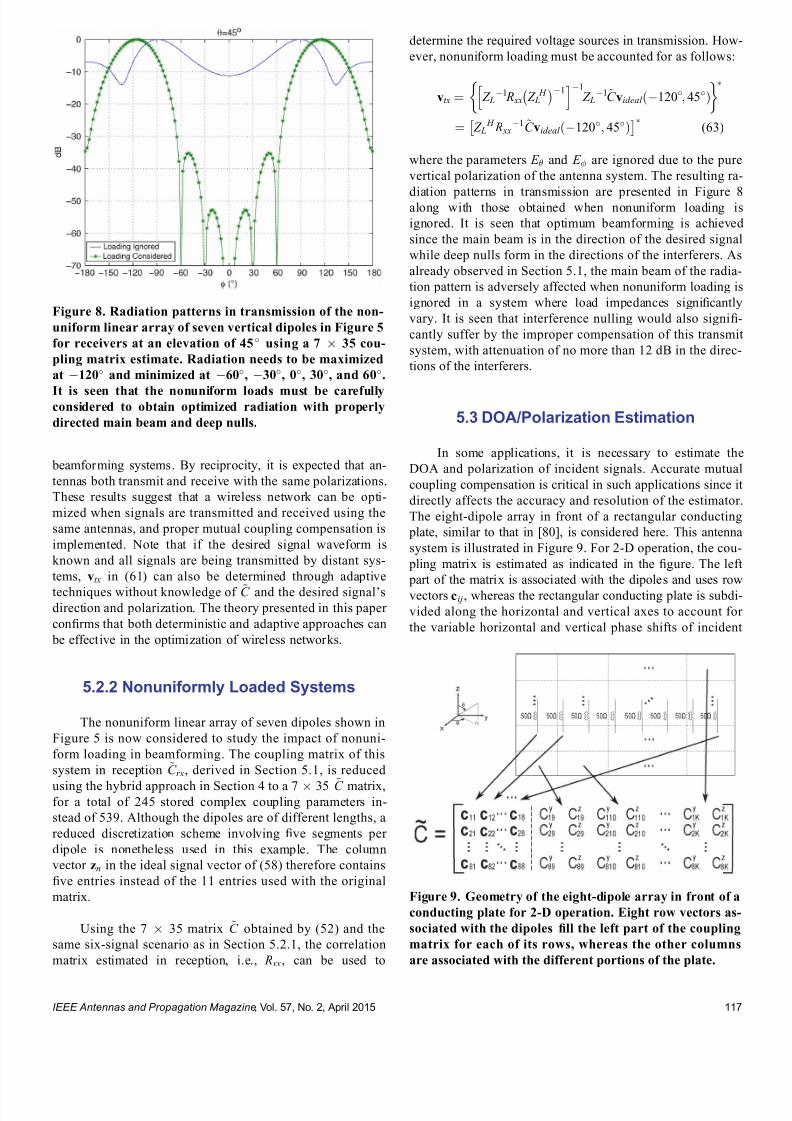
7232019 Unifying the Theory of Mutual Coupling Compensation in Antenna Arrays
httpslidepdfcomreaderfullunifying-the-theory-of-mutual-coupling-compensation-in-antenna-arrays 1419
beamforming systems By reciprocity it is expected that an-
tennas both transmit and receive with the same polarizations
These results suggest that a wireless network can be opti-
mized when signals are transmitted and received using the
same antennas and proper mutual coupling compensation is
implemented Note that if the desired signal waveform is
known and all signals are being transmitted by distant sys-
tems vtx in (61) can also be determined through adaptive
techniques without knowledge of ~C and the desired signalrsquosdirection and polarization The theory presented in this paper
con1047297rms that both deterministic and adaptive approaches can
be effective in the optimization of wireless networks
522 Nonuniformly Loaded Systems
The nonuniform linear array of seven dipoles shown in
Figure 5 is now considered to study the impact of nonuni-
form loading in beamforming The coupling matrix of this
system in reception ~C rx derived in Section 51 is reduced
using the hybrid approach in Section 4 to a 7 35 ~C matrixfor a total of 245 stored complex coupling parameters in-
stead of 539 Although the dipoles are of different lengths a
reduced discretization scheme involving 1047297ve segments per
dipole is nonetheless used in this example The column
vector zn in the ideal signal vector of (58) therefore contains
1047297ve entries instead of the 11 entries used with the original
matrix
Using the 7 35 matrix ~C obtained by (52) and the
same six-signal scenario as in Section 521 the correlation
matrix estimated in reception ie R xx can be used to
determine the required voltage sources in transmission How-
ever nonuniform loading must be accounted for as follows
vtx frac14 Z L1 R xx Z L
H 1
h i1
Z L1~C videal eth120 45THORN
frac14 Z L H R xx
1~C videal eth120 45THORN
(63)
where the parameters E and E are ignored due to the pure
vertical polarization of the antenna system The resulting ra-
diation patterns in transmission are presented in Figure 8along with those obtained when nonuniform loading is
ignored It is seen that optimum beamforming is achieved
since the main beam is in the direction of the desired signal
while deep nulls form in the directions of the interferers As
already observed in Section 51 the main beam of the radia-
tion pattern is adversely affected when nonuniform loading is
ignored in a system where load impedances signi1047297cantly
vary It is seen that interference nulling would also signi1047297-
cantly suffer by the improper compensation of this transmit
system with attenuation of no more than 12 dB in the direc-
tions of the interferers
53 DOAPolarization Estimation
In some applications it is necessary to estimate the
DOA and polarization of incident signals Accurate mutual
coupling compensation is critical in such applications since it
directly affects the accuracy and resolution of the estimator
The eight-dipole array in front of a rectangular conducting
plate similar to that in [80] is considered here This antenna
system is illustrated in Figure 9 For 2-D operation the cou-
pling matrix is estimated as indicated in the 1047297gure The left
part of the matrix is associated with the dipoles and uses row
vectors cij whereas the rectangular conducting plate is subdi-
vided along the horizontal and vertical axes to account for
the variable horizontal and vertical phase shifts of incident
Figure 8 Radiation patterns in transmission of the non-
uniform linear array of seven vertical dipoles in Figure 5
for receivers at an elevation of 45 using a 7 35 cou-
pling matrix estimate Radiation needs to be maximized
at 120 and minimized at 60 30 0 30 and 60
It is seen that the nonuniform loads must be carefullyconsidered to obtain optimized radiation with properly
directed main beam and deep nulls
Figure 9 Geometry of the eight-dipole array in front of a
conducting plate for 2-D operation Eight row vectors as-
sociated with the dipoles 1047297ll the left part of the coupling
matrix for each of its rows whereas the other columns
are associated with the different portions of the plate
IEEE Antennas and Propagation Magazine Vol 57 No 2 April 2015 117
7232019 Unifying the Theory of Mutual Coupling Compensation in Antenna Arrays
httpslidepdfcomreaderfullunifying-the-theory-of-mutual-coupling-compensation-in-antenna-arrays 1519
signals Due to the 1047297nite dimensions of the conducting plate
the polarizations of the array elements may have horizontal
components and both horizontally and vertically oriented in-
cident 1047297elds have to be accounted for on the plate using the
complex scalar parameters C yij and C z
ij respectively
This antenna system is modeled with FEKO [99] using
the method of moments The dipoles are modeled by thin
wires having a length of 612 cm spaced 49 cm apart and
centrally terminated into 50- load impedances The rectan-
gular plate is modeled by a thin 3916-cm-wide and 24-cm-high perfectly conducting surface located 3 cm behind the
dipoles The numerical calculations are performed for an op-
erating frequency of 245 GHz Reordering the entries of the
right part of the matrix for mathematical conciseness the
coupling matrix estimate is obtained by the equations in
Table 1 with the current matrix having the following form
I frac14
z frac12 I wires
s J z J y
24 35frac14
z
I11 I18
I81 I88
24
35
s
J z 91 J z 98
J zK 1 J zK 8
J y91 J y98
J yK 1 J yK 8
2666666437777775
26666666666664
37777777777775
(64)
where z and s are the dipole segment length and conduct-
ing plate patch area respectively I ij is a column vector con-
taining the electric currents on the segments of element i due
to the excitation of element j and J yij and J zij are the y- and
z -directed electric current densities on patch i of the conduct-
ing plate due to the excitation of element j The ideal signal
vector of this problem takes the following form
videal eth E E THORN
frac14
E sin
e j 2 sin ethx1 cos thorny1 sin THORNthornz1 cos frac12
e j 2
sin ethx8 cos thorny8 sin THORNthornz8 cos frac12
e j 2 eth y9 sin sin thorn z 9 cos THORN
e j 2
eth y K sin sin thorn z K cos THORN
266666664
377777775
eth E cos sin thorn E cos THORN
e j2
eth y9 sin sin thorn z 9 cos THORN
e j2
eth y K sin sin thorn z K cos THORN
2
64
3
75
26666666666666664
37777777777777775
(65)
where x j y j and z j are column vectors containing the x y
and z physical locations of the wire segments for j 8 and
y j and z j are scalar values of the y and z locations of the con-
ducting plate patches for j 9 Note that this formulation
assumes that the conducting plate is located at x frac14 0 The nu-
merical solution of this problem involved a total of 104 wire
segments and 2923 surface patches which required approxi-
mately 150 MB of storage and 51 s of runtime to obtain each
of the columns of (64) Since two columns are required to
account for both y- and z -directed currents on each patch the
coupling matrix estimate turns out to be an 8 5950 matrix
Using the size-reduction guidelines presented in Section 4
the size of the estimate can be reduced at the expense of
some performance degradation Here the method is imple-
mented by subdividing the wires into 1047297ve segments each for
a total of 40 wire segments instead of 104 and the conduct-
ing plate into 70 patches 10 wide by 7 high instead of
2923 The size of the coupling matrix estimate then reduces
to 8 180 for a total of 1440 stored complex coupling pa-
rameters instead of 47 600 This is done by computing thesteering vectors for both vertically and horizontally polarized
signals arriving from 85 85 and 25 1725
with angular increments of 10 These two sets of steering
vectors are obtained by substituting videal eth 1 0THORN and
videal eth 0 1THORN as the columns of the matrix V ideal 0 in (52) for
324 different combinations of and Since two polariza-
tions are considered the total number of calibration points is
648 The matrix V ideal in (52) is then a 180 648 matrix con-
taining the ideal signal vectors for the reduced discretization
scheme and the 648 calibration points
The popular MUltiple SIgnal Classi1047297cation (MUSIC)algorithm described in [100 ndash 102] is employed here to per-
form DOA estimation in a polarization diverse scenario By
the theory of this paper the MUSIC DOA spectrum can be
expressed as
P eth THORN frac14 1
min eth A H ATHORN1 A H E N E N
H Ah i (66)
where
A frac14 ~C videal eth 1 0THORN videal eth 0 1THORNfrac12 (67)
minfrac12 is the smallest eigenvalue of the matrix inside the
brackets and E N is the matrix containing the noise eigen-
vectors obtained through the eigendecomposition of the cor-
relation matrix A signal scenario involving two plane waves
arriving from eth THORNfrac14eth30 60THORN and eth THORN frac14 eth0 45THORN re-
spectively is considered In addition the two signals are
circularly polarized The 1047297rst signal is RHCP ie eth E E THORN frac14eth j 1THORN whereas the second signal is LHCP ie eth E E THORN frac14eth1 j THORN The eigenvalue decomposition of the correlation matrix
provides six noise eigenvectors which are associated with
the six smallest eigenvalues to 1047297ll the matrix E N in (66) The
2-D DOA spectra are presented in Figure 10
For comparison the DOA spectra obtained without
compensation with a square coupling matrix having dimen-
sions 8 8 and with the full 8 5950 matrix are also
shown The accuracies and resolutions obtained with the
larger matrices in Figure 10c and d are seen to be signi1047297-
cantly better The reduced 8 180 matrix is seen to be a
very reasonable compromise with a slight performance degra-
dation but a reduction of approximately 97 of the memory
requirement and computations required for the evaluation of
the DOA spectra
IEEE Antennas and Propagation Magazine Vol 57 No 2 April 2015118
7232019 Unifying the Theory of Mutual Coupling Compensation in Antenna Arrays
httpslidepdfcomreaderfullunifying-the-theory-of-mutual-coupling-compensation-in-antenna-arrays 1619
It is important to note here that the 8 180 ~C matrixcan also be determined with measurements using (51) where
the matrix V is 1047297lled with measured steering vectors In the
case studied in this section 648 measured steering vectors
are necessary to obtain ~C This is a substantial reduction
compared with the number of measurements required for 2-D
operation using conventional means More details on this are
available in [89]
6 Conclusion
This paper has thoroughly reviewed the limitations of current mutual coupling compensation methods Through the
derivation of clear theoretical foundations that apply to both
receive and transmit systems the theory of mutual coupling
compensation was uni1047297ed to provide ef 1047297cient mutual coupling
compensation methods that can be employed with systems of
arbitrary geometries Reciprocity relationships were clearly
derived based on the receive and transmit formulations
thereby allowing the use of receive-mode compensation data
for both reception and transmission if the reciprocity relation-
ships are employed properly Both theoretical and experimen-
tal techniques can be used to evaluate mutual coupling by the
presented theory This theory can be veri1047297ed in a straight-forward fashion using proven electromagnetic codes and the
examples given in this paper on retrodirective systems beam-
formers and DOA estimation can be followed by the reader
for validation Finally this theory will likely 1047297nd several other
applications than those presented and contributes to the areas
of antenna theory mutual coupling analysis complex struc-
ture modeling and antenna measurements
7 AppendixDerivation of Analytical
Formulations in Table 1
The analytical formulations presented in Table 1 are
better understood using the various equivalent circuits of an-
tenna systems shown in Figure 11 In receive-mode the
open-circuit voltages are given by
voc A frac14 Z ANT I T videal (68)
voc L frac14 ethZ L thorn Z THORN I T
L videal (69)
voc frac14 ZI T scvideal (70)
Figure 10 2-D DOA estimation using the eight-dipole linear array in front of a rectangular con-
ducting plate for two circularly polarized signals from eth THORN frac14 eth30 60THORN and eth0 45THORN using
MUSIC Mutual coupling compensation implemented with an 8 180 coupling matrix estimate is
seen to give very satisfying performance and ef 1047297ciency with sharp peaks toward the two signals
IEEE Antennas and Propagation Magazine Vol 57 No 2 April 2015 119
7232019 Unifying the Theory of Mutual Coupling Compensation in Antenna Arrays
httpslidepdfcomreaderfullunifying-the-theory-of-mutual-coupling-compensation-in-antenna-arrays 1719
This is consistent with classic antenna theory presented in
[6] The port voltages should be equal irrespective of the
method By circuit theory these are given by
vrx frac14 Z LethZ L thorn Z ANT THORN1
voc A (71)
frac14 Z LethZ L thorn Z THORN1voc L
(72)
frac14 Z LethZ L thorn Z THORN1voc (73)
Substituting (68) ndash (70) into (71) ndash (73) and performing some
matrix manipulations gives
vrx frac14 Z LethZ L thorn Z ANT THORN1
Z ANT I T videal (74)
frac14 Z L I T L videal (75)
frac14 Z LethZ L thorn Z THORN1ZI T
scvideal (76)
The admittance formulations are obtained by substituting
Z L frac14 Y L1 Z ANT frac14 Y ANT
1 and Z frac14 Y 1 into (74) ndash (76) For
example (76) gives
vrx frac14 Y 1 L Y 1
L thorn Y 1 1
Y 1 I T scvideal
frac14 Y 1 L Y LethY L thorn Y THORN1
YY 1 I T scvideal
frac14 ethY L thorn Y THORN1 I T
scvideal (77)
In transmit-mode the radiated 1047297elds are scaled by v A v L
and v which are obtained by voltage division in 1) and 3)
In 2) v L is simply equal to vtx The admittance formulations
in transmit-mode are obtained in the same fashion as the ex-
ample of (77)
8 References
[1] H S Lui H T Hui and M S Leong ldquoA note on the mutualcoupling problems in transmitting and receiving antenna arraysrdquo IEEE Antennas Propag Mag vol 51 no 5 pp 171 ndash 176 Oct 2009
[2] C A Balanis Antenna Theory Analysis and Design 2nd ed NewYork NY USA Wiley 1997
[3] R C Hansen Phased Array Antennas New York NY USA Wiley1998
[4] T A Milligan Modern Antenna Design 2nd ed New York NYUSA Wiley 2005
[5] R J Mailloux Phased Array Antenna Handbook 2nd ed BostonMA USA Artech House 2005[6] S A Schelkunoff and H T Friis Antennas Theory and Practice
New York NY USA Wiley 1952[7] R P Meys ldquoA summary of the transmitting and receiving properties
of antennasrdquo IEEE Antennas Propag Mag vol 42 no 3 pp 49 ndash 53Jun 2000
[8] S Henault ldquoEvaluation of electromagnetic coupling in antenna sys-tems A uni1047297ed theory and its applicationsrdquo PhD dissertation DeptElect Comput Eng Royal Military College of Canada KingstonON Canada Jan 2012
[9] S Henault Y M M Antar S Rajan R Inkol and S Wang ldquoThemultiple antenna induced EMF method for the precise calculation of thecoupling matrix in a receiving antenna arrayrdquo Progr Electromagn Res M vol 8 pp 103 ndash 118 2009
[10] P S Carter ldquoCircuit relations in radiating systems and applications toantenna problemsrdquo Proc IRE vol 20 no 6 pp 1004 ndash 1041 Jun 1932
[11] H E King ldquoMutual impedance of unequal length antennas in echelonrdquo IRE Trans Antennas Propag vol AP-5 no 3 pp 306 ndash 313 Jul 1957
[12] J H Richmond and N H Geary ldquoMutual impedance of nonplanar-skew sinusoidal dipolesrdquo IEEE Trans Antennas Propag vol AP-23no 3 pp 412 ndash 414 May 1975
[13] J D Kraus Antennas 2nd ed New York NY USA McGraw-Hill1988
[14] S A Mitilineos C A Papagianni G I Verikaki and C N CapsalisldquoDesign of switched beam planar arrays using the method of geneticalgorithmsrdquo Progr Electromagn Res vol 46 pp 105 ndash 126 2004
[15] A W Love ldquoComment On the equivalent circuit of a receiving antennardquo IEEE Antennas Propag Mag vol 44 no 5 pp 124 ndash 125 Oct 2002
[16] J B Andersen and R G Vaughan ldquoTransmitting receiving and scat-tering properties of antennasrdquo IEEE Antennas Propag Mag vol 45no 4 pp 93 ndash 98 Aug 2003
[17] J Van Bladel ldquoOn the equivalent circuit of a receiving antennardquo
IEEE Antennas Propag Mag vol 44 no 1 pp 164 ndash
165 Feb 2002[18] R E Collin ldquoLimitations on the Thevenin and Norton equivalent cir-cuits for a receiving antennardquo IEEE Antennas Propag Mag vol 45no 2 pp 119 ndash 124 Apr 2003
[19] C T Tai ldquoA Critical study of the circuit relations of two distant an-tennasrdquo IEEE Antennas Propag Mag vol 44 no 6 pp 32 ndash 37Dec 2002
[20] C T Tai ldquoCorrection V A critical study of the circuit relations of twodistant antennasrdquo IEEE Antennas Propag Mag vol 45 no 1 p 125Feb 2003
[21] A W Love ldquoCorrection V A critical study of the circuit relations of twodistant antennasrdquo IEEE Antennas Propag Mag vol 45 no 2 p 42Apr 2003
[22] C G Montgomery R H Dicke and E M Purcell Principles of Microwave Circuits New York NY USA McGraw-Hill 1948
[23] S Ramo and J Whinnery Fields and Waves in Modern Radio 2nd ed New York NY USA Wiley 1953
[24] S Silver Microwave Antenna Theory and Design New York NYUSA McGraw-Hill 1949
[25] R C Hansen ldquoRelationships between antennas as scatterers and asradiatorsrdquo Proc IEEE vol 77 no 5 pp 659 ndash 662 May 1989
[26] C C Su ldquoOn the equivalent generator voltage and generator internalimpedance for receiving antennasrdquo IEEE Trans Antennas Propagvol 51 no 2 pp 279 ndash 285 Feb 2003
[27] S R Best and B C Kaanta ldquoA tutorial on the receiving and scattering properties of antennasrdquo IEEE Antennas Propag Mag vol 51 no 5 pp 26 ndash 37 Oct 2009
[28] J W Wallace and R Mehmood ldquoOn the accuracy of equivalent circuit models for multi-antenna systemsrdquo IEEE Trans Antennas Propagvol 60 no 2 pp 540 ndash 547 Feb 2012
[29] D M Pozar ldquoThe active element patternrdquo IEEE Trans Antennas Pro- pag vol 42 no 8 pp 1176 ndash 1178 Aug 1994
Figure 11 Equivalent circuits of (left) transmit and (right)
receive antenna systems for the three different loading con-
ditions given in Table 1 These equivalent circuits use vec-
tors and matrices to represent voltages and impedances
IEEE Antennas and Propagation Magazine Vol 57 No 2 April 2015120
7232019 Unifying the Theory of Mutual Coupling Compensation in Antenna Arrays
httpslidepdfcomreaderfullunifying-the-theory-of-mutual-coupling-compensation-in-antenna-arrays 1819
[30] D F Kelley and W L Stutzman ldquoArray antenna pattern modelingmethods that include mutual coupling effectsrdquo IEEE Trans Antennas Propag vol 41 no 12 pp 1625 ndash 1632 Dec 1993
[31] K Takamizawa ldquoAnalysis of highly coupled wideband antenna arraysusing scattering parameter network modelsrdquo PhD dissertation DeptElect Comput Eng Virginia Polytech Inst State Univ BlacksburgVA USA Dec 2002
[32] D M Pozar ldquoA relation between the active input impedance and theactive element pattern of a phased arrayrdquo IEEE Trans Antennas Propag vol 51 no 9 pp 2486 ndash 2489 Sep 2003
[33] D F Kelley ldquoRelationships between active element patterns and mutual impedance matrices in phased array antennasrdquo in Proc IEEE Int Symp Antennas Propag 2002 pp 524 ndash 527
[34] D F Kelley ldquo
Embedded element patterns and mutual impedancematrices in the terminated phased array environmentrdquo in Proc IEEE Int Symp Antennas Propag 2005 pp 659 ndash 662
[35] R F Harrington ldquoAntenna excitation for maximum gainrdquo IEEE Trans Antennas Propag vol AP-13 no 6 pp 896 ndash 903 Nov 1965
[36] H Rogier and E Bonek ldquoAnalytical spherical-mode-based compensa-tion of mutual coupling in uniform circular arrays for direction-of-arrivalestimationrdquo Int J Electron Commun vol 60 no 3 pp 179 ndash 189Mar 2006
[37] A T De Hoop ldquoThe N-port receiving antenna and its equivalent elec-trical networkrdquo Philips Res Rep vol 30 pp 302 ndash 315 1975
[38] P S Kildal ldquoEquivalent circuits of receive antennas in signal process-ing arraysrdquo Microw Opt Technol Lett vol 21 no 4 pp 244 ndash 246May 1999
[39] K F Warnick B Woestenburg L Belostotski and P Russer ldquoMinimiz-ing the noise penalty due to mutual coupling for a receiving arrayrdquo IEEE Trans Antennas Propag vol 57 no 6 pp 1634 ndash 1644 Jun 2009
[40] R O Schmidt ldquoMultilinear array manifold interpolationrdquo IEEE TransSignal Process vol 40 no 4 pp 857 ndash 866 Apr 1992
[41] A J Weiss and B Friedlander ldquoManifold interpolation for diversely po-larized arraysrdquo Proc Inst Elect Eng V Radar Sonar Navig vol 141no 1 pp 19 ndash 24 Feb 1994
[42] R J Allard and D H Werner ldquoThe model-based parameter estimationof antenna radiation patterns using windowed interpolation and sphericalharmonicsrdquo IEEE Trans Antennas Propag vol 51 no 8 pp 1891 ndash 1906 Aug 2003
[43] M Landmann and G Del Galdo ldquoEf 1047297cient antenna description for MIMO channel modelling and estimationrdquo in Proc 7th Eur ConfWireless Technol Amsterdam The Netherlands 2004 pp 217 ndash 220
[44] G Del Galdo J Lotze M Landmann and M Haardt ldquoModelling and manipulation of polarimetric antenna beam patterns via sphericalharmonicsrdquo in Proc 14th Eur Signal Process Conf Florence ItalySep 2006 pp 1 ndash 5
[45] F Belloni A Richter and V Koivunen ldquo
DoA estimation via manifold separation for arbitrary array structuresrdquo IEEE Trans Signal Processvol 55 no 10 pp 4800 ndash 4810 Oct 2007
[46] H T Hui ldquoDecoupling methods for the mutual coupling effect in an-tenna arrays A reviewrdquo Recent Patents Eng vol 1 no 2 pp 187 ndash 193 Jun 2007
[47] T Su and H Ling ldquoOn modeling mutual coupling in antenna arraysusing the coupling matrixrdquo Microw Opt Technol Lett vol 28 no 4 pp 231 ndash 237 Feb 2001
[48] P Darwood P N Fletcher and G S Hilton ldquoMutual couplingcompensation in small planar array antennasrdquo Proc Inst Elect Eng V
Microw Antennas Propag vol 145 no 1 pp 1 ndash 6 Feb 1998[49] H Steyskal and J S Herd ldquoMutual coupling compensation in small array
antennasrdquo IEEE Trans Antennas Propag vol 38 no 12 pp 1971 ndash 1975 Dec 1990
[50] I J Gupta and A A Ksienski ldquoEffect of mutual coupling on the performance of adaptive arraysrdquo IEEE Trans Antennas Propag
vol AP-31 no 5 pp 785 ndash 791 Sep 1983[51] C C Yeh M L Leou and D R Ucci ldquoBearing estimations with mu-
tual coupling presentrdquo IEEE Trans Antennas Propag vol 37 no 10 pp 1332 ndash 1335 Oct 1989
[52] C Roller and W Wasylkiwskyj ldquoEffects of mutual coupling on super-resolution DF in linear arraysrdquo in Proc IEEE Int Conf AcoustSpeech Signal Process vol 5 1992 pp 257 ndash 260
[53] Z Huang C A Balanis and C R Birtcher ldquoMutual couplingcompensation in UCAs Simulations and experimentrdquo IEEE Trans Antennas Propag vol 54 no 11 pp 3082 ndash 3086 Nov 2006
[54] K C Lee and T H Chu ldquoA circuit model for mutual couplinganalysis of a 1047297nite antenna arrayrdquo IEEE Trans Electromagn Compatvol 38 no 3 pp 483 ndash 489 Aug 1996
[55] K W Lo and T B Vu ldquoSimple S-parameter model for receiving an-tenna arrayrdquo Electron Lett vol 24 no 20 pp 1264 ndash 1266 Sep 1988
[56] K M Pasala and E M Friel ldquoMutual coupling effects and their reduction in wideband direction of arrival estimationrdquo IEEE Trans Aerosp Electron Syst vol 30 no 4 pp 1116 ndash 1122 Apr 1994
[57] R S Adve and T K Sarkar ldquoCompensation for the effects of mutualcoupling on direct data domain adaptive algorithmsrdquo IEEE Trans An-tennas Propag vol 48 no 1 pp 86 ndash 94 Jan 2000
[58] R F Harrington Field Computation by Moment Methods New York NY USA Wiley 1968
[59] J Pierre and M Kaveh ldquoExperimental performance of calibration and direction-1047297nding algorithmsrdquo in Proc IEEE Int Conf Acoust SpeechSignal Process vol 2 Toronto ON Canada Apr 1991 pp 1365 ndash 1368
[60] T Su K Dandekar and H Ling ldquoSimulation of mutual couplingeffect in circular arrays for direction-1047297nding applicationsrdquo Microw
Opt Technol Lett vol 26 no 5 pp 331 ndash
336 Sep 2000[61] K R Dandekar H Ling and G Xu ldquoExperimental study of mutualcoupling compensation in smart antenna applicationsrdquo IEEE TransWireless Commun vol 1 no 3 pp 480 ndash 487 Jul 2002
[62] H T Hui ldquoReducing the mutual coupling effect in adaptive nullingusing a re-de1047297ned mutual impedancerdquo IEEE Microw Wireless Compon Lett vol 12 no 5 pp 178 ndash 180 May 2002
[63] H T Hui ldquoCompensating for the mutual coupling effect in direction1047297nding based on a new calculation method for mutual impedancerdquo IEEE Antennas Wireless Propag Lett vol 2 no 1 pp 26 ndash 29 2003
[64] H T Hui ldquoImproved compensation for the mutual coupling effect ina dipole array for direction 1047297ndingrdquo IEEE Trans Antennas Propagvol 51 no 9 pp 2498 ndash 2503 Sep 2003
[65] H T Hui ldquoA practical approach to compensate for the mutual couplingeffect in an adaptive dipole arrayrdquo IEEE Trans Antennas Propagvol 52 no 5 pp 1262 ndash 1269 May 2004
[66] H T Hui ldquoA new de1047297nition of mutual impedance for application in di-
pole receiving antenna arraysrdquo IEEE Antennas Wireless Propag Lettvol 3 no 1 pp 364 ndash 367 Dec 2004
[67] S Henault and Y M M Antar ldquoWideband analysis of mutual couplingcompensation methodsrdquo Int J Antennas Propag vol 2011 2011Art ID 756 153
[68] B Friedlander and A J Weiss ldquoDirection 1047297nding in the presence of mutual couplingrdquo IEEE Trans Antennas Propag vol 39 no 3 pp 273 ndash 284 Mar 1991
[69] E K L Hung ldquoA critical study of a self-calibrating direction-1047297ndingmethod for arraysrdquo IEEE Trans Signal Process vol 42 no 2 pp 471 ndash 474 Feb 1994
[70] F S Sellone and A Serra ldquoA novel online mutual coupling compen-sation algorithm for uniform and linear arraysrdquo IEEE Trans Signal Process vol 55 no 2 pp 560 ndash 573 Feb 2007
[71] M Lin and L Yang ldquoBlind calibration and DOA estimation with uni-form circular arrays in the presence of mutual couplingrdquo IEEE Anten-
nas Wireless Propag Lett vol 5 no 1 pp 315 ndash
318 Dec 2006[72] D Y Gao B H Wang and Y Guo ldquoComments on lsquoBlind calibrationand DOA estimation with uniform circular arrays in the presence of mutual couplingrsquordquo IEEE Antennas Wireless Propag Lett vol 5 no 1 pp 566 ndash 568 Dec 2006
[73] M Lin and L Yang ldquoReply to the comments on lsquoBlind calibration and DOA estimation with uniform circular arrays in the presence of mutualcouplingrsquordquo IEEE Antennas Wireless Propag Lett vol 5 no 1 pp 568 ndash 569 Dec 2006
[74] Q Bao C C Ko and W Zhi ldquoDOA estimation under unknownmutual coupling and multipathrdquo IEEE Trans Aerosp Electron Systvol 41 no 2 pp 565 ndash 573 Apr 2005
[75] Z Ye and C Liu ldquoOn the resiliency of MUSIC direction 1047297nding against antenna sensor couplingrdquo IEEE Trans Antennas Propag vol 56no 2 pp 371 ndash 380 Feb 2008
[76] Z Ye and C Liu ldquo2-D DOA estimation in the presence of mutualcouplingrdquo IEEE Trans Antennas Propag vol 56 no 10 pp 3150 ndash
3158 Oct 2008[77] Y Zhang Q Wan and A M Huang ldquoLocalization of narrow band
sources in the presence of mutual coupling via sparse solution 1047297ndingrdquo Progr Electromagn Res vol 86 pp 243 ndash 257 2008
[78] T Svantesson ldquoAntennas and propagation from a signal processing perspectiverdquo PhD dissertation Dept Signals Syst Chalmers UnivTechnol Goumlteborg Sweden 2001
[79] S Henault and Y M M Antar ldquoLimitations of online calibrationmethodsrdquo in Proc IEEE Int Symp Antennas Propag Toronto ONCanada Jul 2010 pp 1 ndash 4
[80] I J Gupta et al ldquoAn experimental study of antenna array calibrationrdquo IEEE Trans Antennas Propag vol 51 no 3 pp 664 ndash 667 Mar 2003
[81] C K E Lau R S Adve and T K Sarkar ldquoMinimum norm mutual cou- pling compensation with applications in direction of arrival estimationrdquo IEEE Trans Antennas Propag vol 52 no 8 pp 2034 ndash 2041 Aug 2004
IEEE Antennas and Propagation Magazine Vol 57 No 2 April 2015 121
7232019 Unifying the Theory of Mutual Coupling Compensation in Antenna Arrays
httpslidepdfcomreaderfullunifying-the-theory-of-mutual-coupling-compensation-in-antenna-arrays 1919
[82] Q Y Yuan Q Chen and K Sawaya ldquoAccurate DOA estimation usingarray antenna with arbitrary geometryrdquo IEEE Trans Antennas Propagvol 53 no 4 pp 1352 ndash 1357 Apr 2005
[83] S Henault Y M M Antar S Rajan R Inkol and S Wang ldquoEffectsof mutual coupling on the accuracy of adcock direction 1047297nding systemsrdquo IEEE Trans Aerosp Electron Syst vol 48 no 4 pp 2990 ndash 3005Oct 2012
[84] T Su and H Ling ldquoOn the simultaneous modeling of array mutualcoupling and array-platform interactionsrdquo Microw Opt Technol Lettvol 33 no 3 pp 167 ndash 171 May 2002
[85] A Ferreol E Boyer P Larzabal and M Haardt ldquoOn the introductionof an extended coupling matrix for a 2D bearing estimation with an ex- perimental RF systemrdquo Signal Process vol 87 no 9 pp 2005 ndash 2016
Sep 2007[86] J B Andersen and H H Rasmussen ldquoDecoupling and descatteringnetworks for antennasrdquo IEEE Trans Antennas Propag vol AP-24no 6 pp 841 ndash 846 Nov 1976
[87] M Kragalott M S Kluskens D A Zolnick W M Dorsey and J A Valenzi ldquoA toolset independent hybrid method for calculatingantenna couplingrdquo IEEE Trans Antennas Propag vol 59 no 2 pp 443 ndash 451 Feb 2011
[88] A E H Love ldquoThe integration of equations of propagation of electricwavesrdquo Philos Trans Roy Soc London A Math Phys Sci vol 197 pp 1 ndash 45 1901
[89] S Henault S K Podilchak S M Mikki and Y M M Antar ldquoA meth-odology for mutual coupling estimation and compensation in antennasrdquo IEEE Trans Antennas Propag vol 61 no 3 pp 1119 ndash 1131Mar 2013
[90] S Henault and Y M M Antar ldquoOn the interpolation of radiation pat-terns in the calibration of antenna arraysrdquo in IEEE Int Symp Antennas
Propag Spokane WA USA Jul 2011 pp 1747 ndash 1750[91] S Henault and Y M M Antar ldquoA hybrid approach for antenna array
calibrationrdquo in Proc IEEE Int Symp Antennas Propag SpokaneWA USA Jul 2011 pp 1751 ndash 1754
[92] C Pon ldquoRetrodirective array using the heterodyne techniquerdquo IEEE Trans Antennas Propag vol 12 no 2 pp 176 ndash 180 Mar 1964
[93] A F Kay ldquoComments on self-phasing array antennas and electronicallyadaptive antenna systemsrdquo IEEE Trans Antennas Propag vol AP-12no 6 pp 792 ndash 793 Nov 1964
[94] V F Fusco ldquoResponse of retrodirective array in the presence of multi- ple spatially separated sourcesrdquo IEEE Trans Antennas Propag vol 54no 4 pp 1352 ndash 1354 Apr 2006
[95] NEC-2 Manual Lawrence Livermore National Laboratory LivermoreCA USA 1996
[96] L C Van Atta ldquoElectromagnetic re1047298ectorrdquo US Patent 2 908 002Oct 6 1959
[97] T Larsen ldquo
Re1047298
ector arraysrdquo
IEEE Trans Antennas Propag vol AP-14no 6 pp 689 ndash 693 Nov 1966[98] J Appel-Hansen ldquoA van Atta re1047298ector consisting of half-wave dipolesrdquo
IEEE Trans Antennas Propag vol AP-14 no 6 pp 694 ndash 700 Nov 1966
[99] FEKO-Comprehensive EM Solutions [Online] Available httpwwwfekoinfo
[100] R O Schmidt ldquoMultiple emitter location and signal parameter estima-tionrdquo IEEE Trans Antennas Propag vol AP-34 no 3 pp 276 ndash 280Mar 1986
[101] R O Schmidt and R Franks ldquoMultiple source DF signal processingAn experimental systemrdquo IEEE Trans Antennas Propag vol AP-34no 3 pp 281 ndash 290 Mar 1986
[102] E R Ferrara and T M Parks ldquoDirection 1047297nding with an array of antennas having diverse polarizationsrdquo IEEE Trans Antennas Propagvol AP-31 no 2 pp 231 ndash 236 Mar 1983
Simon Henault received the BEng degreefrom Laval University Queacutebec City QCCanada in 2001 and the MASc and PhDdegrees from the Royal Military College of Canada Kingston ON Canada in 2008 and 2012 respectively all in electrical engineering
Since 1998 he has been with CanadarsquosDepartment of National Defence in variouscapacities including two years as a facultymember with the Royal Military College of Canada and multiple assignments with De-fence Research and Development CanadaHe has expertise in antenna radio frequency
and signal processing systems employed in a variety of electronic warfarespace communication and unmanned aerial vehicle platforms
Dr Henault is a regular Reviewer for several journals and conferences
Yahia M M Antar (Srsquo73 ndash Mrsquo76 ndash SMrsquo85 ndash LFrsquo00) received the BSc (Hons) degree fromAlexandria University Alexandria Egypt in1966 and the MSc and PhD degrees fromthe University of Manitoba Winnipeg MBCanada in 1971 and 1975 respectively all inelectrical engineering
In 1977 he held a Government of Canada
Visiting Fellowship with the Communica-tions Research Centre Ottawa ON Canadawhere he worked with the Space TechnologyDirectorate on communications antennas for satellite systems In May 1979 he joined the
Division of Electrical Engineering National Research Council of CanadaOttawa where he worked on polarization radar applications in remote sens-ing of precipitation radio wave propagation electromagnetic scatteringand radar cross-section investigations In November 1987 he joined thestaff of the Department of Electrical and Computer Engineering Royal Mil-itary College of Canada Kingston ON where he has held the position of Professor since 1990 and is currently the Vice Dean for defense and secu-rity research He has authored or coauthored about 200 journal papersmany chapters in books and about 400 refereed conference papers holdsseveral patents has chaired several national and international conferencesand has given plenary talks at many conferences He has supervised and cosupervised over 80 PhD and MSc theses at the Royal Military Collegeof Canada and at Queenrsquos University Kingston several of which have re-ceived the Governor General of Canada Gold Medal the outstanding PhDthesis of the Division of Applied Science as well as many Best Paper Awardsin major international symposia He served as the Chairman of the Canadian Nationa l Commis sion for Radio Scienc e (CNC URSI 1999 ndash 2008) and the Commission B National Chair (1993 ndash 1999) and held an adjunct ap- pointme nt at the Univer sity of Manito ba and has a cross appoint ment at Queenrsquos University
Dr Antar is a Fellow of the Engineering Institute of Canada and theElectromagnetic Academy He serves as an Associate Editor for the IEEEA NTENNAS AND PROPAGATION MAGAZINE served as an Associate Editor for the IEEE TRANSACTIONS ON A NTENNAS AND PROPAGATION and theIEEE A NTENNAS AND WIRELESS PROPAGATION LETTERS and was a mem- ber of the Editorial Board of the International Journal of RF and MicrowaveComputer-Aided Engineering He served on Natural Sciences and Engineer-ing Research Council of Canada grant selection and strategic grant commit-
tees on Ontario Early Research Awards panels and on review panels for the National Science Foundation In May 2002 he was awarded a Tier 1Canada Research Chair in Electromagnetic Engineering which has been re-newed in 2009 In 2003 he was awarded the Royal Military College of Canada ldquoExcellence in Researchrdquo Prize and the RMCC Class of 1965Teaching Excellence Award in 2012 He was elected by the Council of theInternational Union of Radio Science to the Board as Vice President in Au-gust 2008 and in 2013 and to the IEEE Antennas and Propagation SocietyAdministration Committee in December 2009 On January 31 2011 he wasappointed Member of the Canadian Defence Science Advisory Board He ison the IEEE Antennas and Propagation Society Distinguished LecturersProgram In October 2012 he received the Queenrsquos Diamond Jubilee Medalfrom the Governor General of Canada in recognition of his contribution toCanada He was a recipient of the 2014 IEEE Canada RA Fessenden Silver Medal and the 2015 IEEE Canada J M Ham Outstanding EngineeringEducation Award
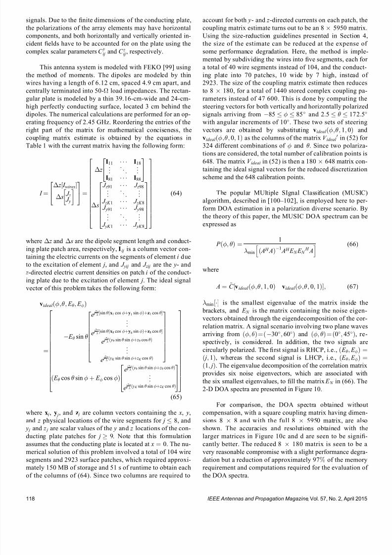
7232019 Unifying the Theory of Mutual Coupling Compensation in Antenna Arrays
httpslidepdfcomreaderfullunifying-the-theory-of-mutual-coupling-compensation-in-antenna-arrays 1519
signals Due to the 1047297nite dimensions of the conducting plate
the polarizations of the array elements may have horizontal
components and both horizontally and vertically oriented in-
cident 1047297elds have to be accounted for on the plate using the
complex scalar parameters C yij and C z
ij respectively
This antenna system is modeled with FEKO [99] using
the method of moments The dipoles are modeled by thin
wires having a length of 612 cm spaced 49 cm apart and
centrally terminated into 50- load impedances The rectan-
gular plate is modeled by a thin 3916-cm-wide and 24-cm-high perfectly conducting surface located 3 cm behind the
dipoles The numerical calculations are performed for an op-
erating frequency of 245 GHz Reordering the entries of the
right part of the matrix for mathematical conciseness the
coupling matrix estimate is obtained by the equations in
Table 1 with the current matrix having the following form
I frac14
z frac12 I wires
s J z J y
24 35frac14
z
I11 I18
I81 I88
24
35
s
J z 91 J z 98
J zK 1 J zK 8
J y91 J y98
J yK 1 J yK 8
2666666437777775
26666666666664
37777777777775
(64)
where z and s are the dipole segment length and conduct-
ing plate patch area respectively I ij is a column vector con-
taining the electric currents on the segments of element i due
to the excitation of element j and J yij and J zij are the y- and
z -directed electric current densities on patch i of the conduct-
ing plate due to the excitation of element j The ideal signal
vector of this problem takes the following form
videal eth E E THORN
frac14
E sin
e j 2 sin ethx1 cos thorny1 sin THORNthornz1 cos frac12
e j 2
sin ethx8 cos thorny8 sin THORNthornz8 cos frac12
e j 2 eth y9 sin sin thorn z 9 cos THORN
e j 2
eth y K sin sin thorn z K cos THORN
266666664
377777775
eth E cos sin thorn E cos THORN
e j2
eth y9 sin sin thorn z 9 cos THORN
e j2
eth y K sin sin thorn z K cos THORN
2
64
3
75
26666666666666664
37777777777777775
(65)
where x j y j and z j are column vectors containing the x y
and z physical locations of the wire segments for j 8 and
y j and z j are scalar values of the y and z locations of the con-
ducting plate patches for j 9 Note that this formulation
assumes that the conducting plate is located at x frac14 0 The nu-
merical solution of this problem involved a total of 104 wire
segments and 2923 surface patches which required approxi-
mately 150 MB of storage and 51 s of runtime to obtain each
of the columns of (64) Since two columns are required to
account for both y- and z -directed currents on each patch the
coupling matrix estimate turns out to be an 8 5950 matrix
Using the size-reduction guidelines presented in Section 4
the size of the estimate can be reduced at the expense of
some performance degradation Here the method is imple-
mented by subdividing the wires into 1047297ve segments each for
a total of 40 wire segments instead of 104 and the conduct-
ing plate into 70 patches 10 wide by 7 high instead of
2923 The size of the coupling matrix estimate then reduces
to 8 180 for a total of 1440 stored complex coupling pa-
rameters instead of 47 600 This is done by computing thesteering vectors for both vertically and horizontally polarized
signals arriving from 85 85 and 25 1725
with angular increments of 10 These two sets of steering
vectors are obtained by substituting videal eth 1 0THORN and
videal eth 0 1THORN as the columns of the matrix V ideal 0 in (52) for
324 different combinations of and Since two polariza-
tions are considered the total number of calibration points is
648 The matrix V ideal in (52) is then a 180 648 matrix con-
taining the ideal signal vectors for the reduced discretization
scheme and the 648 calibration points
The popular MUltiple SIgnal Classi1047297cation (MUSIC)algorithm described in [100 ndash 102] is employed here to per-
form DOA estimation in a polarization diverse scenario By
the theory of this paper the MUSIC DOA spectrum can be
expressed as
P eth THORN frac14 1
min eth A H ATHORN1 A H E N E N
H Ah i (66)
where
A frac14 ~C videal eth 1 0THORN videal eth 0 1THORNfrac12 (67)
minfrac12 is the smallest eigenvalue of the matrix inside the
brackets and E N is the matrix containing the noise eigen-
vectors obtained through the eigendecomposition of the cor-
relation matrix A signal scenario involving two plane waves
arriving from eth THORNfrac14eth30 60THORN and eth THORN frac14 eth0 45THORN re-
spectively is considered In addition the two signals are
circularly polarized The 1047297rst signal is RHCP ie eth E E THORN frac14eth j 1THORN whereas the second signal is LHCP ie eth E E THORN frac14eth1 j THORN The eigenvalue decomposition of the correlation matrix
provides six noise eigenvectors which are associated with
the six smallest eigenvalues to 1047297ll the matrix E N in (66) The
2-D DOA spectra are presented in Figure 10
For comparison the DOA spectra obtained without
compensation with a square coupling matrix having dimen-
sions 8 8 and with the full 8 5950 matrix are also
shown The accuracies and resolutions obtained with the
larger matrices in Figure 10c and d are seen to be signi1047297-
cantly better The reduced 8 180 matrix is seen to be a
very reasonable compromise with a slight performance degra-
dation but a reduction of approximately 97 of the memory
requirement and computations required for the evaluation of
the DOA spectra
IEEE Antennas and Propagation Magazine Vol 57 No 2 April 2015118
7232019 Unifying the Theory of Mutual Coupling Compensation in Antenna Arrays
httpslidepdfcomreaderfullunifying-the-theory-of-mutual-coupling-compensation-in-antenna-arrays 1619
It is important to note here that the 8 180 ~C matrixcan also be determined with measurements using (51) where
the matrix V is 1047297lled with measured steering vectors In the
case studied in this section 648 measured steering vectors
are necessary to obtain ~C This is a substantial reduction
compared with the number of measurements required for 2-D
operation using conventional means More details on this are
available in [89]
6 Conclusion
This paper has thoroughly reviewed the limitations of current mutual coupling compensation methods Through the
derivation of clear theoretical foundations that apply to both
receive and transmit systems the theory of mutual coupling
compensation was uni1047297ed to provide ef 1047297cient mutual coupling
compensation methods that can be employed with systems of
arbitrary geometries Reciprocity relationships were clearly
derived based on the receive and transmit formulations
thereby allowing the use of receive-mode compensation data
for both reception and transmission if the reciprocity relation-
ships are employed properly Both theoretical and experimen-
tal techniques can be used to evaluate mutual coupling by the
presented theory This theory can be veri1047297ed in a straight-forward fashion using proven electromagnetic codes and the
examples given in this paper on retrodirective systems beam-
formers and DOA estimation can be followed by the reader
for validation Finally this theory will likely 1047297nd several other
applications than those presented and contributes to the areas
of antenna theory mutual coupling analysis complex struc-
ture modeling and antenna measurements
7 AppendixDerivation of Analytical
Formulations in Table 1
The analytical formulations presented in Table 1 are
better understood using the various equivalent circuits of an-
tenna systems shown in Figure 11 In receive-mode the
open-circuit voltages are given by
voc A frac14 Z ANT I T videal (68)
voc L frac14 ethZ L thorn Z THORN I T
L videal (69)
voc frac14 ZI T scvideal (70)
Figure 10 2-D DOA estimation using the eight-dipole linear array in front of a rectangular con-
ducting plate for two circularly polarized signals from eth THORN frac14 eth30 60THORN and eth0 45THORN using
MUSIC Mutual coupling compensation implemented with an 8 180 coupling matrix estimate is
seen to give very satisfying performance and ef 1047297ciency with sharp peaks toward the two signals
IEEE Antennas and Propagation Magazine Vol 57 No 2 April 2015 119
7232019 Unifying the Theory of Mutual Coupling Compensation in Antenna Arrays
httpslidepdfcomreaderfullunifying-the-theory-of-mutual-coupling-compensation-in-antenna-arrays 1719
This is consistent with classic antenna theory presented in
[6] The port voltages should be equal irrespective of the
method By circuit theory these are given by
vrx frac14 Z LethZ L thorn Z ANT THORN1
voc A (71)
frac14 Z LethZ L thorn Z THORN1voc L
(72)
frac14 Z LethZ L thorn Z THORN1voc (73)
Substituting (68) ndash (70) into (71) ndash (73) and performing some
matrix manipulations gives
vrx frac14 Z LethZ L thorn Z ANT THORN1
Z ANT I T videal (74)
frac14 Z L I T L videal (75)
frac14 Z LethZ L thorn Z THORN1ZI T
scvideal (76)
The admittance formulations are obtained by substituting
Z L frac14 Y L1 Z ANT frac14 Y ANT
1 and Z frac14 Y 1 into (74) ndash (76) For
example (76) gives
vrx frac14 Y 1 L Y 1
L thorn Y 1 1
Y 1 I T scvideal
frac14 Y 1 L Y LethY L thorn Y THORN1
YY 1 I T scvideal
frac14 ethY L thorn Y THORN1 I T
scvideal (77)
In transmit-mode the radiated 1047297elds are scaled by v A v L
and v which are obtained by voltage division in 1) and 3)
In 2) v L is simply equal to vtx The admittance formulations
in transmit-mode are obtained in the same fashion as the ex-
ample of (77)
8 References
[1] H S Lui H T Hui and M S Leong ldquoA note on the mutualcoupling problems in transmitting and receiving antenna arraysrdquo IEEE Antennas Propag Mag vol 51 no 5 pp 171 ndash 176 Oct 2009
[2] C A Balanis Antenna Theory Analysis and Design 2nd ed NewYork NY USA Wiley 1997
[3] R C Hansen Phased Array Antennas New York NY USA Wiley1998
[4] T A Milligan Modern Antenna Design 2nd ed New York NYUSA Wiley 2005
[5] R J Mailloux Phased Array Antenna Handbook 2nd ed BostonMA USA Artech House 2005[6] S A Schelkunoff and H T Friis Antennas Theory and Practice
New York NY USA Wiley 1952[7] R P Meys ldquoA summary of the transmitting and receiving properties
of antennasrdquo IEEE Antennas Propag Mag vol 42 no 3 pp 49 ndash 53Jun 2000
[8] S Henault ldquoEvaluation of electromagnetic coupling in antenna sys-tems A uni1047297ed theory and its applicationsrdquo PhD dissertation DeptElect Comput Eng Royal Military College of Canada KingstonON Canada Jan 2012
[9] S Henault Y M M Antar S Rajan R Inkol and S Wang ldquoThemultiple antenna induced EMF method for the precise calculation of thecoupling matrix in a receiving antenna arrayrdquo Progr Electromagn Res M vol 8 pp 103 ndash 118 2009
[10] P S Carter ldquoCircuit relations in radiating systems and applications toantenna problemsrdquo Proc IRE vol 20 no 6 pp 1004 ndash 1041 Jun 1932
[11] H E King ldquoMutual impedance of unequal length antennas in echelonrdquo IRE Trans Antennas Propag vol AP-5 no 3 pp 306 ndash 313 Jul 1957
[12] J H Richmond and N H Geary ldquoMutual impedance of nonplanar-skew sinusoidal dipolesrdquo IEEE Trans Antennas Propag vol AP-23no 3 pp 412 ndash 414 May 1975
[13] J D Kraus Antennas 2nd ed New York NY USA McGraw-Hill1988
[14] S A Mitilineos C A Papagianni G I Verikaki and C N CapsalisldquoDesign of switched beam planar arrays using the method of geneticalgorithmsrdquo Progr Electromagn Res vol 46 pp 105 ndash 126 2004
[15] A W Love ldquoComment On the equivalent circuit of a receiving antennardquo IEEE Antennas Propag Mag vol 44 no 5 pp 124 ndash 125 Oct 2002
[16] J B Andersen and R G Vaughan ldquoTransmitting receiving and scat-tering properties of antennasrdquo IEEE Antennas Propag Mag vol 45no 4 pp 93 ndash 98 Aug 2003
[17] J Van Bladel ldquoOn the equivalent circuit of a receiving antennardquo
IEEE Antennas Propag Mag vol 44 no 1 pp 164 ndash
165 Feb 2002[18] R E Collin ldquoLimitations on the Thevenin and Norton equivalent cir-cuits for a receiving antennardquo IEEE Antennas Propag Mag vol 45no 2 pp 119 ndash 124 Apr 2003
[19] C T Tai ldquoA Critical study of the circuit relations of two distant an-tennasrdquo IEEE Antennas Propag Mag vol 44 no 6 pp 32 ndash 37Dec 2002
[20] C T Tai ldquoCorrection V A critical study of the circuit relations of twodistant antennasrdquo IEEE Antennas Propag Mag vol 45 no 1 p 125Feb 2003
[21] A W Love ldquoCorrection V A critical study of the circuit relations of twodistant antennasrdquo IEEE Antennas Propag Mag vol 45 no 2 p 42Apr 2003
[22] C G Montgomery R H Dicke and E M Purcell Principles of Microwave Circuits New York NY USA McGraw-Hill 1948
[23] S Ramo and J Whinnery Fields and Waves in Modern Radio 2nd ed New York NY USA Wiley 1953
[24] S Silver Microwave Antenna Theory and Design New York NYUSA McGraw-Hill 1949
[25] R C Hansen ldquoRelationships between antennas as scatterers and asradiatorsrdquo Proc IEEE vol 77 no 5 pp 659 ndash 662 May 1989
[26] C C Su ldquoOn the equivalent generator voltage and generator internalimpedance for receiving antennasrdquo IEEE Trans Antennas Propagvol 51 no 2 pp 279 ndash 285 Feb 2003
[27] S R Best and B C Kaanta ldquoA tutorial on the receiving and scattering properties of antennasrdquo IEEE Antennas Propag Mag vol 51 no 5 pp 26 ndash 37 Oct 2009
[28] J W Wallace and R Mehmood ldquoOn the accuracy of equivalent circuit models for multi-antenna systemsrdquo IEEE Trans Antennas Propagvol 60 no 2 pp 540 ndash 547 Feb 2012
[29] D M Pozar ldquoThe active element patternrdquo IEEE Trans Antennas Pro- pag vol 42 no 8 pp 1176 ndash 1178 Aug 1994
Figure 11 Equivalent circuits of (left) transmit and (right)
receive antenna systems for the three different loading con-
ditions given in Table 1 These equivalent circuits use vec-
tors and matrices to represent voltages and impedances
IEEE Antennas and Propagation Magazine Vol 57 No 2 April 2015120
7232019 Unifying the Theory of Mutual Coupling Compensation in Antenna Arrays
httpslidepdfcomreaderfullunifying-the-theory-of-mutual-coupling-compensation-in-antenna-arrays 1819
[30] D F Kelley and W L Stutzman ldquoArray antenna pattern modelingmethods that include mutual coupling effectsrdquo IEEE Trans Antennas Propag vol 41 no 12 pp 1625 ndash 1632 Dec 1993
[31] K Takamizawa ldquoAnalysis of highly coupled wideband antenna arraysusing scattering parameter network modelsrdquo PhD dissertation DeptElect Comput Eng Virginia Polytech Inst State Univ BlacksburgVA USA Dec 2002
[32] D M Pozar ldquoA relation between the active input impedance and theactive element pattern of a phased arrayrdquo IEEE Trans Antennas Propag vol 51 no 9 pp 2486 ndash 2489 Sep 2003
[33] D F Kelley ldquoRelationships between active element patterns and mutual impedance matrices in phased array antennasrdquo in Proc IEEE Int Symp Antennas Propag 2002 pp 524 ndash 527
[34] D F Kelley ldquo
Embedded element patterns and mutual impedancematrices in the terminated phased array environmentrdquo in Proc IEEE Int Symp Antennas Propag 2005 pp 659 ndash 662
[35] R F Harrington ldquoAntenna excitation for maximum gainrdquo IEEE Trans Antennas Propag vol AP-13 no 6 pp 896 ndash 903 Nov 1965
[36] H Rogier and E Bonek ldquoAnalytical spherical-mode-based compensa-tion of mutual coupling in uniform circular arrays for direction-of-arrivalestimationrdquo Int J Electron Commun vol 60 no 3 pp 179 ndash 189Mar 2006
[37] A T De Hoop ldquoThe N-port receiving antenna and its equivalent elec-trical networkrdquo Philips Res Rep vol 30 pp 302 ndash 315 1975
[38] P S Kildal ldquoEquivalent circuits of receive antennas in signal process-ing arraysrdquo Microw Opt Technol Lett vol 21 no 4 pp 244 ndash 246May 1999
[39] K F Warnick B Woestenburg L Belostotski and P Russer ldquoMinimiz-ing the noise penalty due to mutual coupling for a receiving arrayrdquo IEEE Trans Antennas Propag vol 57 no 6 pp 1634 ndash 1644 Jun 2009
[40] R O Schmidt ldquoMultilinear array manifold interpolationrdquo IEEE TransSignal Process vol 40 no 4 pp 857 ndash 866 Apr 1992
[41] A J Weiss and B Friedlander ldquoManifold interpolation for diversely po-larized arraysrdquo Proc Inst Elect Eng V Radar Sonar Navig vol 141no 1 pp 19 ndash 24 Feb 1994
[42] R J Allard and D H Werner ldquoThe model-based parameter estimationof antenna radiation patterns using windowed interpolation and sphericalharmonicsrdquo IEEE Trans Antennas Propag vol 51 no 8 pp 1891 ndash 1906 Aug 2003
[43] M Landmann and G Del Galdo ldquoEf 1047297cient antenna description for MIMO channel modelling and estimationrdquo in Proc 7th Eur ConfWireless Technol Amsterdam The Netherlands 2004 pp 217 ndash 220
[44] G Del Galdo J Lotze M Landmann and M Haardt ldquoModelling and manipulation of polarimetric antenna beam patterns via sphericalharmonicsrdquo in Proc 14th Eur Signal Process Conf Florence ItalySep 2006 pp 1 ndash 5
[45] F Belloni A Richter and V Koivunen ldquo
DoA estimation via manifold separation for arbitrary array structuresrdquo IEEE Trans Signal Processvol 55 no 10 pp 4800 ndash 4810 Oct 2007
[46] H T Hui ldquoDecoupling methods for the mutual coupling effect in an-tenna arrays A reviewrdquo Recent Patents Eng vol 1 no 2 pp 187 ndash 193 Jun 2007
[47] T Su and H Ling ldquoOn modeling mutual coupling in antenna arraysusing the coupling matrixrdquo Microw Opt Technol Lett vol 28 no 4 pp 231 ndash 237 Feb 2001
[48] P Darwood P N Fletcher and G S Hilton ldquoMutual couplingcompensation in small planar array antennasrdquo Proc Inst Elect Eng V
Microw Antennas Propag vol 145 no 1 pp 1 ndash 6 Feb 1998[49] H Steyskal and J S Herd ldquoMutual coupling compensation in small array
antennasrdquo IEEE Trans Antennas Propag vol 38 no 12 pp 1971 ndash 1975 Dec 1990
[50] I J Gupta and A A Ksienski ldquoEffect of mutual coupling on the performance of adaptive arraysrdquo IEEE Trans Antennas Propag
vol AP-31 no 5 pp 785 ndash 791 Sep 1983[51] C C Yeh M L Leou and D R Ucci ldquoBearing estimations with mu-
tual coupling presentrdquo IEEE Trans Antennas Propag vol 37 no 10 pp 1332 ndash 1335 Oct 1989
[52] C Roller and W Wasylkiwskyj ldquoEffects of mutual coupling on super-resolution DF in linear arraysrdquo in Proc IEEE Int Conf AcoustSpeech Signal Process vol 5 1992 pp 257 ndash 260
[53] Z Huang C A Balanis and C R Birtcher ldquoMutual couplingcompensation in UCAs Simulations and experimentrdquo IEEE Trans Antennas Propag vol 54 no 11 pp 3082 ndash 3086 Nov 2006
[54] K C Lee and T H Chu ldquoA circuit model for mutual couplinganalysis of a 1047297nite antenna arrayrdquo IEEE Trans Electromagn Compatvol 38 no 3 pp 483 ndash 489 Aug 1996
[55] K W Lo and T B Vu ldquoSimple S-parameter model for receiving an-tenna arrayrdquo Electron Lett vol 24 no 20 pp 1264 ndash 1266 Sep 1988
[56] K M Pasala and E M Friel ldquoMutual coupling effects and their reduction in wideband direction of arrival estimationrdquo IEEE Trans Aerosp Electron Syst vol 30 no 4 pp 1116 ndash 1122 Apr 1994
[57] R S Adve and T K Sarkar ldquoCompensation for the effects of mutualcoupling on direct data domain adaptive algorithmsrdquo IEEE Trans An-tennas Propag vol 48 no 1 pp 86 ndash 94 Jan 2000
[58] R F Harrington Field Computation by Moment Methods New York NY USA Wiley 1968
[59] J Pierre and M Kaveh ldquoExperimental performance of calibration and direction-1047297nding algorithmsrdquo in Proc IEEE Int Conf Acoust SpeechSignal Process vol 2 Toronto ON Canada Apr 1991 pp 1365 ndash 1368
[60] T Su K Dandekar and H Ling ldquoSimulation of mutual couplingeffect in circular arrays for direction-1047297nding applicationsrdquo Microw
Opt Technol Lett vol 26 no 5 pp 331 ndash
336 Sep 2000[61] K R Dandekar H Ling and G Xu ldquoExperimental study of mutualcoupling compensation in smart antenna applicationsrdquo IEEE TransWireless Commun vol 1 no 3 pp 480 ndash 487 Jul 2002
[62] H T Hui ldquoReducing the mutual coupling effect in adaptive nullingusing a re-de1047297ned mutual impedancerdquo IEEE Microw Wireless Compon Lett vol 12 no 5 pp 178 ndash 180 May 2002
[63] H T Hui ldquoCompensating for the mutual coupling effect in direction1047297nding based on a new calculation method for mutual impedancerdquo IEEE Antennas Wireless Propag Lett vol 2 no 1 pp 26 ndash 29 2003
[64] H T Hui ldquoImproved compensation for the mutual coupling effect ina dipole array for direction 1047297ndingrdquo IEEE Trans Antennas Propagvol 51 no 9 pp 2498 ndash 2503 Sep 2003
[65] H T Hui ldquoA practical approach to compensate for the mutual couplingeffect in an adaptive dipole arrayrdquo IEEE Trans Antennas Propagvol 52 no 5 pp 1262 ndash 1269 May 2004
[66] H T Hui ldquoA new de1047297nition of mutual impedance for application in di-
pole receiving antenna arraysrdquo IEEE Antennas Wireless Propag Lettvol 3 no 1 pp 364 ndash 367 Dec 2004
[67] S Henault and Y M M Antar ldquoWideband analysis of mutual couplingcompensation methodsrdquo Int J Antennas Propag vol 2011 2011Art ID 756 153
[68] B Friedlander and A J Weiss ldquoDirection 1047297nding in the presence of mutual couplingrdquo IEEE Trans Antennas Propag vol 39 no 3 pp 273 ndash 284 Mar 1991
[69] E K L Hung ldquoA critical study of a self-calibrating direction-1047297ndingmethod for arraysrdquo IEEE Trans Signal Process vol 42 no 2 pp 471 ndash 474 Feb 1994
[70] F S Sellone and A Serra ldquoA novel online mutual coupling compen-sation algorithm for uniform and linear arraysrdquo IEEE Trans Signal Process vol 55 no 2 pp 560 ndash 573 Feb 2007
[71] M Lin and L Yang ldquoBlind calibration and DOA estimation with uni-form circular arrays in the presence of mutual couplingrdquo IEEE Anten-
nas Wireless Propag Lett vol 5 no 1 pp 315 ndash
318 Dec 2006[72] D Y Gao B H Wang and Y Guo ldquoComments on lsquoBlind calibrationand DOA estimation with uniform circular arrays in the presence of mutual couplingrsquordquo IEEE Antennas Wireless Propag Lett vol 5 no 1 pp 566 ndash 568 Dec 2006
[73] M Lin and L Yang ldquoReply to the comments on lsquoBlind calibration and DOA estimation with uniform circular arrays in the presence of mutualcouplingrsquordquo IEEE Antennas Wireless Propag Lett vol 5 no 1 pp 568 ndash 569 Dec 2006
[74] Q Bao C C Ko and W Zhi ldquoDOA estimation under unknownmutual coupling and multipathrdquo IEEE Trans Aerosp Electron Systvol 41 no 2 pp 565 ndash 573 Apr 2005
[75] Z Ye and C Liu ldquoOn the resiliency of MUSIC direction 1047297nding against antenna sensor couplingrdquo IEEE Trans Antennas Propag vol 56no 2 pp 371 ndash 380 Feb 2008
[76] Z Ye and C Liu ldquo2-D DOA estimation in the presence of mutualcouplingrdquo IEEE Trans Antennas Propag vol 56 no 10 pp 3150 ndash
3158 Oct 2008[77] Y Zhang Q Wan and A M Huang ldquoLocalization of narrow band
sources in the presence of mutual coupling via sparse solution 1047297ndingrdquo Progr Electromagn Res vol 86 pp 243 ndash 257 2008
[78] T Svantesson ldquoAntennas and propagation from a signal processing perspectiverdquo PhD dissertation Dept Signals Syst Chalmers UnivTechnol Goumlteborg Sweden 2001
[79] S Henault and Y M M Antar ldquoLimitations of online calibrationmethodsrdquo in Proc IEEE Int Symp Antennas Propag Toronto ONCanada Jul 2010 pp 1 ndash 4
[80] I J Gupta et al ldquoAn experimental study of antenna array calibrationrdquo IEEE Trans Antennas Propag vol 51 no 3 pp 664 ndash 667 Mar 2003
[81] C K E Lau R S Adve and T K Sarkar ldquoMinimum norm mutual cou- pling compensation with applications in direction of arrival estimationrdquo IEEE Trans Antennas Propag vol 52 no 8 pp 2034 ndash 2041 Aug 2004
IEEE Antennas and Propagation Magazine Vol 57 No 2 April 2015 121
7232019 Unifying the Theory of Mutual Coupling Compensation in Antenna Arrays
httpslidepdfcomreaderfullunifying-the-theory-of-mutual-coupling-compensation-in-antenna-arrays 1919
[82] Q Y Yuan Q Chen and K Sawaya ldquoAccurate DOA estimation usingarray antenna with arbitrary geometryrdquo IEEE Trans Antennas Propagvol 53 no 4 pp 1352 ndash 1357 Apr 2005
[83] S Henault Y M M Antar S Rajan R Inkol and S Wang ldquoEffectsof mutual coupling on the accuracy of adcock direction 1047297nding systemsrdquo IEEE Trans Aerosp Electron Syst vol 48 no 4 pp 2990 ndash 3005Oct 2012
[84] T Su and H Ling ldquoOn the simultaneous modeling of array mutualcoupling and array-platform interactionsrdquo Microw Opt Technol Lettvol 33 no 3 pp 167 ndash 171 May 2002
[85] A Ferreol E Boyer P Larzabal and M Haardt ldquoOn the introductionof an extended coupling matrix for a 2D bearing estimation with an ex- perimental RF systemrdquo Signal Process vol 87 no 9 pp 2005 ndash 2016
Sep 2007[86] J B Andersen and H H Rasmussen ldquoDecoupling and descatteringnetworks for antennasrdquo IEEE Trans Antennas Propag vol AP-24no 6 pp 841 ndash 846 Nov 1976
[87] M Kragalott M S Kluskens D A Zolnick W M Dorsey and J A Valenzi ldquoA toolset independent hybrid method for calculatingantenna couplingrdquo IEEE Trans Antennas Propag vol 59 no 2 pp 443 ndash 451 Feb 2011
[88] A E H Love ldquoThe integration of equations of propagation of electricwavesrdquo Philos Trans Roy Soc London A Math Phys Sci vol 197 pp 1 ndash 45 1901
[89] S Henault S K Podilchak S M Mikki and Y M M Antar ldquoA meth-odology for mutual coupling estimation and compensation in antennasrdquo IEEE Trans Antennas Propag vol 61 no 3 pp 1119 ndash 1131Mar 2013
[90] S Henault and Y M M Antar ldquoOn the interpolation of radiation pat-terns in the calibration of antenna arraysrdquo in IEEE Int Symp Antennas
Propag Spokane WA USA Jul 2011 pp 1747 ndash 1750[91] S Henault and Y M M Antar ldquoA hybrid approach for antenna array
calibrationrdquo in Proc IEEE Int Symp Antennas Propag SpokaneWA USA Jul 2011 pp 1751 ndash 1754
[92] C Pon ldquoRetrodirective array using the heterodyne techniquerdquo IEEE Trans Antennas Propag vol 12 no 2 pp 176 ndash 180 Mar 1964
[93] A F Kay ldquoComments on self-phasing array antennas and electronicallyadaptive antenna systemsrdquo IEEE Trans Antennas Propag vol AP-12no 6 pp 792 ndash 793 Nov 1964
[94] V F Fusco ldquoResponse of retrodirective array in the presence of multi- ple spatially separated sourcesrdquo IEEE Trans Antennas Propag vol 54no 4 pp 1352 ndash 1354 Apr 2006
[95] NEC-2 Manual Lawrence Livermore National Laboratory LivermoreCA USA 1996
[96] L C Van Atta ldquoElectromagnetic re1047298ectorrdquo US Patent 2 908 002Oct 6 1959
[97] T Larsen ldquo
Re1047298
ector arraysrdquo
IEEE Trans Antennas Propag vol AP-14no 6 pp 689 ndash 693 Nov 1966[98] J Appel-Hansen ldquoA van Atta re1047298ector consisting of half-wave dipolesrdquo
IEEE Trans Antennas Propag vol AP-14 no 6 pp 694 ndash 700 Nov 1966
[99] FEKO-Comprehensive EM Solutions [Online] Available httpwwwfekoinfo
[100] R O Schmidt ldquoMultiple emitter location and signal parameter estima-tionrdquo IEEE Trans Antennas Propag vol AP-34 no 3 pp 276 ndash 280Mar 1986
[101] R O Schmidt and R Franks ldquoMultiple source DF signal processingAn experimental systemrdquo IEEE Trans Antennas Propag vol AP-34no 3 pp 281 ndash 290 Mar 1986
[102] E R Ferrara and T M Parks ldquoDirection 1047297nding with an array of antennas having diverse polarizationsrdquo IEEE Trans Antennas Propagvol AP-31 no 2 pp 231 ndash 236 Mar 1983
Simon Henault received the BEng degreefrom Laval University Queacutebec City QCCanada in 2001 and the MASc and PhDdegrees from the Royal Military College of Canada Kingston ON Canada in 2008 and 2012 respectively all in electrical engineering
Since 1998 he has been with CanadarsquosDepartment of National Defence in variouscapacities including two years as a facultymember with the Royal Military College of Canada and multiple assignments with De-fence Research and Development CanadaHe has expertise in antenna radio frequency
and signal processing systems employed in a variety of electronic warfarespace communication and unmanned aerial vehicle platforms
Dr Henault is a regular Reviewer for several journals and conferences
Yahia M M Antar (Srsquo73 ndash Mrsquo76 ndash SMrsquo85 ndash LFrsquo00) received the BSc (Hons) degree fromAlexandria University Alexandria Egypt in1966 and the MSc and PhD degrees fromthe University of Manitoba Winnipeg MBCanada in 1971 and 1975 respectively all inelectrical engineering
In 1977 he held a Government of Canada
Visiting Fellowship with the Communica-tions Research Centre Ottawa ON Canadawhere he worked with the Space TechnologyDirectorate on communications antennas for satellite systems In May 1979 he joined the
Division of Electrical Engineering National Research Council of CanadaOttawa where he worked on polarization radar applications in remote sens-ing of precipitation radio wave propagation electromagnetic scatteringand radar cross-section investigations In November 1987 he joined thestaff of the Department of Electrical and Computer Engineering Royal Mil-itary College of Canada Kingston ON where he has held the position of Professor since 1990 and is currently the Vice Dean for defense and secu-rity research He has authored or coauthored about 200 journal papersmany chapters in books and about 400 refereed conference papers holdsseveral patents has chaired several national and international conferencesand has given plenary talks at many conferences He has supervised and cosupervised over 80 PhD and MSc theses at the Royal Military Collegeof Canada and at Queenrsquos University Kingston several of which have re-ceived the Governor General of Canada Gold Medal the outstanding PhDthesis of the Division of Applied Science as well as many Best Paper Awardsin major international symposia He served as the Chairman of the Canadian Nationa l Commis sion for Radio Scienc e (CNC URSI 1999 ndash 2008) and the Commission B National Chair (1993 ndash 1999) and held an adjunct ap- pointme nt at the Univer sity of Manito ba and has a cross appoint ment at Queenrsquos University
Dr Antar is a Fellow of the Engineering Institute of Canada and theElectromagnetic Academy He serves as an Associate Editor for the IEEEA NTENNAS AND PROPAGATION MAGAZINE served as an Associate Editor for the IEEE TRANSACTIONS ON A NTENNAS AND PROPAGATION and theIEEE A NTENNAS AND WIRELESS PROPAGATION LETTERS and was a mem- ber of the Editorial Board of the International Journal of RF and MicrowaveComputer-Aided Engineering He served on Natural Sciences and Engineer-ing Research Council of Canada grant selection and strategic grant commit-
tees on Ontario Early Research Awards panels and on review panels for the National Science Foundation In May 2002 he was awarded a Tier 1Canada Research Chair in Electromagnetic Engineering which has been re-newed in 2009 In 2003 he was awarded the Royal Military College of Canada ldquoExcellence in Researchrdquo Prize and the RMCC Class of 1965Teaching Excellence Award in 2012 He was elected by the Council of theInternational Union of Radio Science to the Board as Vice President in Au-gust 2008 and in 2013 and to the IEEE Antennas and Propagation SocietyAdministration Committee in December 2009 On January 31 2011 he wasappointed Member of the Canadian Defence Science Advisory Board He ison the IEEE Antennas and Propagation Society Distinguished LecturersProgram In October 2012 he received the Queenrsquos Diamond Jubilee Medalfrom the Governor General of Canada in recognition of his contribution toCanada He was a recipient of the 2014 IEEE Canada RA Fessenden Silver Medal and the 2015 IEEE Canada J M Ham Outstanding EngineeringEducation Award
7232019 Unifying the Theory of Mutual Coupling Compensation in Antenna Arrays
httpslidepdfcomreaderfullunifying-the-theory-of-mutual-coupling-compensation-in-antenna-arrays 1619
It is important to note here that the 8 180 ~C matrixcan also be determined with measurements using (51) where
the matrix V is 1047297lled with measured steering vectors In the
case studied in this section 648 measured steering vectors
are necessary to obtain ~C This is a substantial reduction
compared with the number of measurements required for 2-D
operation using conventional means More details on this are
available in [89]
6 Conclusion
This paper has thoroughly reviewed the limitations of current mutual coupling compensation methods Through the
derivation of clear theoretical foundations that apply to both
receive and transmit systems the theory of mutual coupling
compensation was uni1047297ed to provide ef 1047297cient mutual coupling
compensation methods that can be employed with systems of
arbitrary geometries Reciprocity relationships were clearly
derived based on the receive and transmit formulations
thereby allowing the use of receive-mode compensation data
for both reception and transmission if the reciprocity relation-
ships are employed properly Both theoretical and experimen-
tal techniques can be used to evaluate mutual coupling by the
presented theory This theory can be veri1047297ed in a straight-forward fashion using proven electromagnetic codes and the
examples given in this paper on retrodirective systems beam-
formers and DOA estimation can be followed by the reader
for validation Finally this theory will likely 1047297nd several other
applications than those presented and contributes to the areas
of antenna theory mutual coupling analysis complex struc-
ture modeling and antenna measurements
7 AppendixDerivation of Analytical
Formulations in Table 1
The analytical formulations presented in Table 1 are
better understood using the various equivalent circuits of an-
tenna systems shown in Figure 11 In receive-mode the
open-circuit voltages are given by
voc A frac14 Z ANT I T videal (68)
voc L frac14 ethZ L thorn Z THORN I T
L videal (69)
voc frac14 ZI T scvideal (70)
Figure 10 2-D DOA estimation using the eight-dipole linear array in front of a rectangular con-
ducting plate for two circularly polarized signals from eth THORN frac14 eth30 60THORN and eth0 45THORN using
MUSIC Mutual coupling compensation implemented with an 8 180 coupling matrix estimate is
seen to give very satisfying performance and ef 1047297ciency with sharp peaks toward the two signals
IEEE Antennas and Propagation Magazine Vol 57 No 2 April 2015 119
7232019 Unifying the Theory of Mutual Coupling Compensation in Antenna Arrays
httpslidepdfcomreaderfullunifying-the-theory-of-mutual-coupling-compensation-in-antenna-arrays 1719
This is consistent with classic antenna theory presented in
[6] The port voltages should be equal irrespective of the
method By circuit theory these are given by
vrx frac14 Z LethZ L thorn Z ANT THORN1
voc A (71)
frac14 Z LethZ L thorn Z THORN1voc L
(72)
frac14 Z LethZ L thorn Z THORN1voc (73)
Substituting (68) ndash (70) into (71) ndash (73) and performing some
matrix manipulations gives
vrx frac14 Z LethZ L thorn Z ANT THORN1
Z ANT I T videal (74)
frac14 Z L I T L videal (75)
frac14 Z LethZ L thorn Z THORN1ZI T
scvideal (76)
The admittance formulations are obtained by substituting
Z L frac14 Y L1 Z ANT frac14 Y ANT
1 and Z frac14 Y 1 into (74) ndash (76) For
example (76) gives
vrx frac14 Y 1 L Y 1
L thorn Y 1 1
Y 1 I T scvideal
frac14 Y 1 L Y LethY L thorn Y THORN1
YY 1 I T scvideal
frac14 ethY L thorn Y THORN1 I T
scvideal (77)
In transmit-mode the radiated 1047297elds are scaled by v A v L
and v which are obtained by voltage division in 1) and 3)
In 2) v L is simply equal to vtx The admittance formulations
in transmit-mode are obtained in the same fashion as the ex-
ample of (77)
8 References
[1] H S Lui H T Hui and M S Leong ldquoA note on the mutualcoupling problems in transmitting and receiving antenna arraysrdquo IEEE Antennas Propag Mag vol 51 no 5 pp 171 ndash 176 Oct 2009
[2] C A Balanis Antenna Theory Analysis and Design 2nd ed NewYork NY USA Wiley 1997
[3] R C Hansen Phased Array Antennas New York NY USA Wiley1998
[4] T A Milligan Modern Antenna Design 2nd ed New York NYUSA Wiley 2005
[5] R J Mailloux Phased Array Antenna Handbook 2nd ed BostonMA USA Artech House 2005[6] S A Schelkunoff and H T Friis Antennas Theory and Practice
New York NY USA Wiley 1952[7] R P Meys ldquoA summary of the transmitting and receiving properties
of antennasrdquo IEEE Antennas Propag Mag vol 42 no 3 pp 49 ndash 53Jun 2000
[8] S Henault ldquoEvaluation of electromagnetic coupling in antenna sys-tems A uni1047297ed theory and its applicationsrdquo PhD dissertation DeptElect Comput Eng Royal Military College of Canada KingstonON Canada Jan 2012
[9] S Henault Y M M Antar S Rajan R Inkol and S Wang ldquoThemultiple antenna induced EMF method for the precise calculation of thecoupling matrix in a receiving antenna arrayrdquo Progr Electromagn Res M vol 8 pp 103 ndash 118 2009
[10] P S Carter ldquoCircuit relations in radiating systems and applications toantenna problemsrdquo Proc IRE vol 20 no 6 pp 1004 ndash 1041 Jun 1932
[11] H E King ldquoMutual impedance of unequal length antennas in echelonrdquo IRE Trans Antennas Propag vol AP-5 no 3 pp 306 ndash 313 Jul 1957
[12] J H Richmond and N H Geary ldquoMutual impedance of nonplanar-skew sinusoidal dipolesrdquo IEEE Trans Antennas Propag vol AP-23no 3 pp 412 ndash 414 May 1975
[13] J D Kraus Antennas 2nd ed New York NY USA McGraw-Hill1988
[14] S A Mitilineos C A Papagianni G I Verikaki and C N CapsalisldquoDesign of switched beam planar arrays using the method of geneticalgorithmsrdquo Progr Electromagn Res vol 46 pp 105 ndash 126 2004
[15] A W Love ldquoComment On the equivalent circuit of a receiving antennardquo IEEE Antennas Propag Mag vol 44 no 5 pp 124 ndash 125 Oct 2002
[16] J B Andersen and R G Vaughan ldquoTransmitting receiving and scat-tering properties of antennasrdquo IEEE Antennas Propag Mag vol 45no 4 pp 93 ndash 98 Aug 2003
[17] J Van Bladel ldquoOn the equivalent circuit of a receiving antennardquo
IEEE Antennas Propag Mag vol 44 no 1 pp 164 ndash
165 Feb 2002[18] R E Collin ldquoLimitations on the Thevenin and Norton equivalent cir-cuits for a receiving antennardquo IEEE Antennas Propag Mag vol 45no 2 pp 119 ndash 124 Apr 2003
[19] C T Tai ldquoA Critical study of the circuit relations of two distant an-tennasrdquo IEEE Antennas Propag Mag vol 44 no 6 pp 32 ndash 37Dec 2002
[20] C T Tai ldquoCorrection V A critical study of the circuit relations of twodistant antennasrdquo IEEE Antennas Propag Mag vol 45 no 1 p 125Feb 2003
[21] A W Love ldquoCorrection V A critical study of the circuit relations of twodistant antennasrdquo IEEE Antennas Propag Mag vol 45 no 2 p 42Apr 2003
[22] C G Montgomery R H Dicke and E M Purcell Principles of Microwave Circuits New York NY USA McGraw-Hill 1948
[23] S Ramo and J Whinnery Fields and Waves in Modern Radio 2nd ed New York NY USA Wiley 1953
[24] S Silver Microwave Antenna Theory and Design New York NYUSA McGraw-Hill 1949
[25] R C Hansen ldquoRelationships between antennas as scatterers and asradiatorsrdquo Proc IEEE vol 77 no 5 pp 659 ndash 662 May 1989
[26] C C Su ldquoOn the equivalent generator voltage and generator internalimpedance for receiving antennasrdquo IEEE Trans Antennas Propagvol 51 no 2 pp 279 ndash 285 Feb 2003
[27] S R Best and B C Kaanta ldquoA tutorial on the receiving and scattering properties of antennasrdquo IEEE Antennas Propag Mag vol 51 no 5 pp 26 ndash 37 Oct 2009
[28] J W Wallace and R Mehmood ldquoOn the accuracy of equivalent circuit models for multi-antenna systemsrdquo IEEE Trans Antennas Propagvol 60 no 2 pp 540 ndash 547 Feb 2012
[29] D M Pozar ldquoThe active element patternrdquo IEEE Trans Antennas Pro- pag vol 42 no 8 pp 1176 ndash 1178 Aug 1994
Figure 11 Equivalent circuits of (left) transmit and (right)
receive antenna systems for the three different loading con-
ditions given in Table 1 These equivalent circuits use vec-
tors and matrices to represent voltages and impedances
IEEE Antennas and Propagation Magazine Vol 57 No 2 April 2015120
7232019 Unifying the Theory of Mutual Coupling Compensation in Antenna Arrays
httpslidepdfcomreaderfullunifying-the-theory-of-mutual-coupling-compensation-in-antenna-arrays 1819
[30] D F Kelley and W L Stutzman ldquoArray antenna pattern modelingmethods that include mutual coupling effectsrdquo IEEE Trans Antennas Propag vol 41 no 12 pp 1625 ndash 1632 Dec 1993
[31] K Takamizawa ldquoAnalysis of highly coupled wideband antenna arraysusing scattering parameter network modelsrdquo PhD dissertation DeptElect Comput Eng Virginia Polytech Inst State Univ BlacksburgVA USA Dec 2002
[32] D M Pozar ldquoA relation between the active input impedance and theactive element pattern of a phased arrayrdquo IEEE Trans Antennas Propag vol 51 no 9 pp 2486 ndash 2489 Sep 2003
[33] D F Kelley ldquoRelationships between active element patterns and mutual impedance matrices in phased array antennasrdquo in Proc IEEE Int Symp Antennas Propag 2002 pp 524 ndash 527
[34] D F Kelley ldquo
Embedded element patterns and mutual impedancematrices in the terminated phased array environmentrdquo in Proc IEEE Int Symp Antennas Propag 2005 pp 659 ndash 662
[35] R F Harrington ldquoAntenna excitation for maximum gainrdquo IEEE Trans Antennas Propag vol AP-13 no 6 pp 896 ndash 903 Nov 1965
[36] H Rogier and E Bonek ldquoAnalytical spherical-mode-based compensa-tion of mutual coupling in uniform circular arrays for direction-of-arrivalestimationrdquo Int J Electron Commun vol 60 no 3 pp 179 ndash 189Mar 2006
[37] A T De Hoop ldquoThe N-port receiving antenna and its equivalent elec-trical networkrdquo Philips Res Rep vol 30 pp 302 ndash 315 1975
[38] P S Kildal ldquoEquivalent circuits of receive antennas in signal process-ing arraysrdquo Microw Opt Technol Lett vol 21 no 4 pp 244 ndash 246May 1999
[39] K F Warnick B Woestenburg L Belostotski and P Russer ldquoMinimiz-ing the noise penalty due to mutual coupling for a receiving arrayrdquo IEEE Trans Antennas Propag vol 57 no 6 pp 1634 ndash 1644 Jun 2009
[40] R O Schmidt ldquoMultilinear array manifold interpolationrdquo IEEE TransSignal Process vol 40 no 4 pp 857 ndash 866 Apr 1992
[41] A J Weiss and B Friedlander ldquoManifold interpolation for diversely po-larized arraysrdquo Proc Inst Elect Eng V Radar Sonar Navig vol 141no 1 pp 19 ndash 24 Feb 1994
[42] R J Allard and D H Werner ldquoThe model-based parameter estimationof antenna radiation patterns using windowed interpolation and sphericalharmonicsrdquo IEEE Trans Antennas Propag vol 51 no 8 pp 1891 ndash 1906 Aug 2003
[43] M Landmann and G Del Galdo ldquoEf 1047297cient antenna description for MIMO channel modelling and estimationrdquo in Proc 7th Eur ConfWireless Technol Amsterdam The Netherlands 2004 pp 217 ndash 220
[44] G Del Galdo J Lotze M Landmann and M Haardt ldquoModelling and manipulation of polarimetric antenna beam patterns via sphericalharmonicsrdquo in Proc 14th Eur Signal Process Conf Florence ItalySep 2006 pp 1 ndash 5
[45] F Belloni A Richter and V Koivunen ldquo
DoA estimation via manifold separation for arbitrary array structuresrdquo IEEE Trans Signal Processvol 55 no 10 pp 4800 ndash 4810 Oct 2007
[46] H T Hui ldquoDecoupling methods for the mutual coupling effect in an-tenna arrays A reviewrdquo Recent Patents Eng vol 1 no 2 pp 187 ndash 193 Jun 2007
[47] T Su and H Ling ldquoOn modeling mutual coupling in antenna arraysusing the coupling matrixrdquo Microw Opt Technol Lett vol 28 no 4 pp 231 ndash 237 Feb 2001
[48] P Darwood P N Fletcher and G S Hilton ldquoMutual couplingcompensation in small planar array antennasrdquo Proc Inst Elect Eng V
Microw Antennas Propag vol 145 no 1 pp 1 ndash 6 Feb 1998[49] H Steyskal and J S Herd ldquoMutual coupling compensation in small array
antennasrdquo IEEE Trans Antennas Propag vol 38 no 12 pp 1971 ndash 1975 Dec 1990
[50] I J Gupta and A A Ksienski ldquoEffect of mutual coupling on the performance of adaptive arraysrdquo IEEE Trans Antennas Propag
vol AP-31 no 5 pp 785 ndash 791 Sep 1983[51] C C Yeh M L Leou and D R Ucci ldquoBearing estimations with mu-
tual coupling presentrdquo IEEE Trans Antennas Propag vol 37 no 10 pp 1332 ndash 1335 Oct 1989
[52] C Roller and W Wasylkiwskyj ldquoEffects of mutual coupling on super-resolution DF in linear arraysrdquo in Proc IEEE Int Conf AcoustSpeech Signal Process vol 5 1992 pp 257 ndash 260
[53] Z Huang C A Balanis and C R Birtcher ldquoMutual couplingcompensation in UCAs Simulations and experimentrdquo IEEE Trans Antennas Propag vol 54 no 11 pp 3082 ndash 3086 Nov 2006
[54] K C Lee and T H Chu ldquoA circuit model for mutual couplinganalysis of a 1047297nite antenna arrayrdquo IEEE Trans Electromagn Compatvol 38 no 3 pp 483 ndash 489 Aug 1996
[55] K W Lo and T B Vu ldquoSimple S-parameter model for receiving an-tenna arrayrdquo Electron Lett vol 24 no 20 pp 1264 ndash 1266 Sep 1988
[56] K M Pasala and E M Friel ldquoMutual coupling effects and their reduction in wideband direction of arrival estimationrdquo IEEE Trans Aerosp Electron Syst vol 30 no 4 pp 1116 ndash 1122 Apr 1994
[57] R S Adve and T K Sarkar ldquoCompensation for the effects of mutualcoupling on direct data domain adaptive algorithmsrdquo IEEE Trans An-tennas Propag vol 48 no 1 pp 86 ndash 94 Jan 2000
[58] R F Harrington Field Computation by Moment Methods New York NY USA Wiley 1968
[59] J Pierre and M Kaveh ldquoExperimental performance of calibration and direction-1047297nding algorithmsrdquo in Proc IEEE Int Conf Acoust SpeechSignal Process vol 2 Toronto ON Canada Apr 1991 pp 1365 ndash 1368
[60] T Su K Dandekar and H Ling ldquoSimulation of mutual couplingeffect in circular arrays for direction-1047297nding applicationsrdquo Microw
Opt Technol Lett vol 26 no 5 pp 331 ndash
336 Sep 2000[61] K R Dandekar H Ling and G Xu ldquoExperimental study of mutualcoupling compensation in smart antenna applicationsrdquo IEEE TransWireless Commun vol 1 no 3 pp 480 ndash 487 Jul 2002
[62] H T Hui ldquoReducing the mutual coupling effect in adaptive nullingusing a re-de1047297ned mutual impedancerdquo IEEE Microw Wireless Compon Lett vol 12 no 5 pp 178 ndash 180 May 2002
[63] H T Hui ldquoCompensating for the mutual coupling effect in direction1047297nding based on a new calculation method for mutual impedancerdquo IEEE Antennas Wireless Propag Lett vol 2 no 1 pp 26 ndash 29 2003
[64] H T Hui ldquoImproved compensation for the mutual coupling effect ina dipole array for direction 1047297ndingrdquo IEEE Trans Antennas Propagvol 51 no 9 pp 2498 ndash 2503 Sep 2003
[65] H T Hui ldquoA practical approach to compensate for the mutual couplingeffect in an adaptive dipole arrayrdquo IEEE Trans Antennas Propagvol 52 no 5 pp 1262 ndash 1269 May 2004
[66] H T Hui ldquoA new de1047297nition of mutual impedance for application in di-
pole receiving antenna arraysrdquo IEEE Antennas Wireless Propag Lettvol 3 no 1 pp 364 ndash 367 Dec 2004
[67] S Henault and Y M M Antar ldquoWideband analysis of mutual couplingcompensation methodsrdquo Int J Antennas Propag vol 2011 2011Art ID 756 153
[68] B Friedlander and A J Weiss ldquoDirection 1047297nding in the presence of mutual couplingrdquo IEEE Trans Antennas Propag vol 39 no 3 pp 273 ndash 284 Mar 1991
[69] E K L Hung ldquoA critical study of a self-calibrating direction-1047297ndingmethod for arraysrdquo IEEE Trans Signal Process vol 42 no 2 pp 471 ndash 474 Feb 1994
[70] F S Sellone and A Serra ldquoA novel online mutual coupling compen-sation algorithm for uniform and linear arraysrdquo IEEE Trans Signal Process vol 55 no 2 pp 560 ndash 573 Feb 2007
[71] M Lin and L Yang ldquoBlind calibration and DOA estimation with uni-form circular arrays in the presence of mutual couplingrdquo IEEE Anten-
nas Wireless Propag Lett vol 5 no 1 pp 315 ndash
318 Dec 2006[72] D Y Gao B H Wang and Y Guo ldquoComments on lsquoBlind calibrationand DOA estimation with uniform circular arrays in the presence of mutual couplingrsquordquo IEEE Antennas Wireless Propag Lett vol 5 no 1 pp 566 ndash 568 Dec 2006
[73] M Lin and L Yang ldquoReply to the comments on lsquoBlind calibration and DOA estimation with uniform circular arrays in the presence of mutualcouplingrsquordquo IEEE Antennas Wireless Propag Lett vol 5 no 1 pp 568 ndash 569 Dec 2006
[74] Q Bao C C Ko and W Zhi ldquoDOA estimation under unknownmutual coupling and multipathrdquo IEEE Trans Aerosp Electron Systvol 41 no 2 pp 565 ndash 573 Apr 2005
[75] Z Ye and C Liu ldquoOn the resiliency of MUSIC direction 1047297nding against antenna sensor couplingrdquo IEEE Trans Antennas Propag vol 56no 2 pp 371 ndash 380 Feb 2008
[76] Z Ye and C Liu ldquo2-D DOA estimation in the presence of mutualcouplingrdquo IEEE Trans Antennas Propag vol 56 no 10 pp 3150 ndash
3158 Oct 2008[77] Y Zhang Q Wan and A M Huang ldquoLocalization of narrow band
sources in the presence of mutual coupling via sparse solution 1047297ndingrdquo Progr Electromagn Res vol 86 pp 243 ndash 257 2008
[78] T Svantesson ldquoAntennas and propagation from a signal processing perspectiverdquo PhD dissertation Dept Signals Syst Chalmers UnivTechnol Goumlteborg Sweden 2001
[79] S Henault and Y M M Antar ldquoLimitations of online calibrationmethodsrdquo in Proc IEEE Int Symp Antennas Propag Toronto ONCanada Jul 2010 pp 1 ndash 4
[80] I J Gupta et al ldquoAn experimental study of antenna array calibrationrdquo IEEE Trans Antennas Propag vol 51 no 3 pp 664 ndash 667 Mar 2003
[81] C K E Lau R S Adve and T K Sarkar ldquoMinimum norm mutual cou- pling compensation with applications in direction of arrival estimationrdquo IEEE Trans Antennas Propag vol 52 no 8 pp 2034 ndash 2041 Aug 2004
IEEE Antennas and Propagation Magazine Vol 57 No 2 April 2015 121
7232019 Unifying the Theory of Mutual Coupling Compensation in Antenna Arrays
httpslidepdfcomreaderfullunifying-the-theory-of-mutual-coupling-compensation-in-antenna-arrays 1919
[82] Q Y Yuan Q Chen and K Sawaya ldquoAccurate DOA estimation usingarray antenna with arbitrary geometryrdquo IEEE Trans Antennas Propagvol 53 no 4 pp 1352 ndash 1357 Apr 2005
[83] S Henault Y M M Antar S Rajan R Inkol and S Wang ldquoEffectsof mutual coupling on the accuracy of adcock direction 1047297nding systemsrdquo IEEE Trans Aerosp Electron Syst vol 48 no 4 pp 2990 ndash 3005Oct 2012
[84] T Su and H Ling ldquoOn the simultaneous modeling of array mutualcoupling and array-platform interactionsrdquo Microw Opt Technol Lettvol 33 no 3 pp 167 ndash 171 May 2002
[85] A Ferreol E Boyer P Larzabal and M Haardt ldquoOn the introductionof an extended coupling matrix for a 2D bearing estimation with an ex- perimental RF systemrdquo Signal Process vol 87 no 9 pp 2005 ndash 2016
Sep 2007[86] J B Andersen and H H Rasmussen ldquoDecoupling and descatteringnetworks for antennasrdquo IEEE Trans Antennas Propag vol AP-24no 6 pp 841 ndash 846 Nov 1976
[87] M Kragalott M S Kluskens D A Zolnick W M Dorsey and J A Valenzi ldquoA toolset independent hybrid method for calculatingantenna couplingrdquo IEEE Trans Antennas Propag vol 59 no 2 pp 443 ndash 451 Feb 2011
[88] A E H Love ldquoThe integration of equations of propagation of electricwavesrdquo Philos Trans Roy Soc London A Math Phys Sci vol 197 pp 1 ndash 45 1901
[89] S Henault S K Podilchak S M Mikki and Y M M Antar ldquoA meth-odology for mutual coupling estimation and compensation in antennasrdquo IEEE Trans Antennas Propag vol 61 no 3 pp 1119 ndash 1131Mar 2013
[90] S Henault and Y M M Antar ldquoOn the interpolation of radiation pat-terns in the calibration of antenna arraysrdquo in IEEE Int Symp Antennas
Propag Spokane WA USA Jul 2011 pp 1747 ndash 1750[91] S Henault and Y M M Antar ldquoA hybrid approach for antenna array
calibrationrdquo in Proc IEEE Int Symp Antennas Propag SpokaneWA USA Jul 2011 pp 1751 ndash 1754
[92] C Pon ldquoRetrodirective array using the heterodyne techniquerdquo IEEE Trans Antennas Propag vol 12 no 2 pp 176 ndash 180 Mar 1964
[93] A F Kay ldquoComments on self-phasing array antennas and electronicallyadaptive antenna systemsrdquo IEEE Trans Antennas Propag vol AP-12no 6 pp 792 ndash 793 Nov 1964
[94] V F Fusco ldquoResponse of retrodirective array in the presence of multi- ple spatially separated sourcesrdquo IEEE Trans Antennas Propag vol 54no 4 pp 1352 ndash 1354 Apr 2006
[95] NEC-2 Manual Lawrence Livermore National Laboratory LivermoreCA USA 1996
[96] L C Van Atta ldquoElectromagnetic re1047298ectorrdquo US Patent 2 908 002Oct 6 1959
[97] T Larsen ldquo
Re1047298
ector arraysrdquo
IEEE Trans Antennas Propag vol AP-14no 6 pp 689 ndash 693 Nov 1966[98] J Appel-Hansen ldquoA van Atta re1047298ector consisting of half-wave dipolesrdquo
IEEE Trans Antennas Propag vol AP-14 no 6 pp 694 ndash 700 Nov 1966
[99] FEKO-Comprehensive EM Solutions [Online] Available httpwwwfekoinfo
[100] R O Schmidt ldquoMultiple emitter location and signal parameter estima-tionrdquo IEEE Trans Antennas Propag vol AP-34 no 3 pp 276 ndash 280Mar 1986
[101] R O Schmidt and R Franks ldquoMultiple source DF signal processingAn experimental systemrdquo IEEE Trans Antennas Propag vol AP-34no 3 pp 281 ndash 290 Mar 1986
[102] E R Ferrara and T M Parks ldquoDirection 1047297nding with an array of antennas having diverse polarizationsrdquo IEEE Trans Antennas Propagvol AP-31 no 2 pp 231 ndash 236 Mar 1983
Simon Henault received the BEng degreefrom Laval University Queacutebec City QCCanada in 2001 and the MASc and PhDdegrees from the Royal Military College of Canada Kingston ON Canada in 2008 and 2012 respectively all in electrical engineering
Since 1998 he has been with CanadarsquosDepartment of National Defence in variouscapacities including two years as a facultymember with the Royal Military College of Canada and multiple assignments with De-fence Research and Development CanadaHe has expertise in antenna radio frequency
and signal processing systems employed in a variety of electronic warfarespace communication and unmanned aerial vehicle platforms
Dr Henault is a regular Reviewer for several journals and conferences
Yahia M M Antar (Srsquo73 ndash Mrsquo76 ndash SMrsquo85 ndash LFrsquo00) received the BSc (Hons) degree fromAlexandria University Alexandria Egypt in1966 and the MSc and PhD degrees fromthe University of Manitoba Winnipeg MBCanada in 1971 and 1975 respectively all inelectrical engineering
In 1977 he held a Government of Canada
Visiting Fellowship with the Communica-tions Research Centre Ottawa ON Canadawhere he worked with the Space TechnologyDirectorate on communications antennas for satellite systems In May 1979 he joined the
Division of Electrical Engineering National Research Council of CanadaOttawa where he worked on polarization radar applications in remote sens-ing of precipitation radio wave propagation electromagnetic scatteringand radar cross-section investigations In November 1987 he joined thestaff of the Department of Electrical and Computer Engineering Royal Mil-itary College of Canada Kingston ON where he has held the position of Professor since 1990 and is currently the Vice Dean for defense and secu-rity research He has authored or coauthored about 200 journal papersmany chapters in books and about 400 refereed conference papers holdsseveral patents has chaired several national and international conferencesand has given plenary talks at many conferences He has supervised and cosupervised over 80 PhD and MSc theses at the Royal Military Collegeof Canada and at Queenrsquos University Kingston several of which have re-ceived the Governor General of Canada Gold Medal the outstanding PhDthesis of the Division of Applied Science as well as many Best Paper Awardsin major international symposia He served as the Chairman of the Canadian Nationa l Commis sion for Radio Scienc e (CNC URSI 1999 ndash 2008) and the Commission B National Chair (1993 ndash 1999) and held an adjunct ap- pointme nt at the Univer sity of Manito ba and has a cross appoint ment at Queenrsquos University
Dr Antar is a Fellow of the Engineering Institute of Canada and theElectromagnetic Academy He serves as an Associate Editor for the IEEEA NTENNAS AND PROPAGATION MAGAZINE served as an Associate Editor for the IEEE TRANSACTIONS ON A NTENNAS AND PROPAGATION and theIEEE A NTENNAS AND WIRELESS PROPAGATION LETTERS and was a mem- ber of the Editorial Board of the International Journal of RF and MicrowaveComputer-Aided Engineering He served on Natural Sciences and Engineer-ing Research Council of Canada grant selection and strategic grant commit-
tees on Ontario Early Research Awards panels and on review panels for the National Science Foundation In May 2002 he was awarded a Tier 1Canada Research Chair in Electromagnetic Engineering which has been re-newed in 2009 In 2003 he was awarded the Royal Military College of Canada ldquoExcellence in Researchrdquo Prize and the RMCC Class of 1965Teaching Excellence Award in 2012 He was elected by the Council of theInternational Union of Radio Science to the Board as Vice President in Au-gust 2008 and in 2013 and to the IEEE Antennas and Propagation SocietyAdministration Committee in December 2009 On January 31 2011 he wasappointed Member of the Canadian Defence Science Advisory Board He ison the IEEE Antennas and Propagation Society Distinguished LecturersProgram In October 2012 he received the Queenrsquos Diamond Jubilee Medalfrom the Governor General of Canada in recognition of his contribution toCanada He was a recipient of the 2014 IEEE Canada RA Fessenden Silver Medal and the 2015 IEEE Canada J M Ham Outstanding EngineeringEducation Award
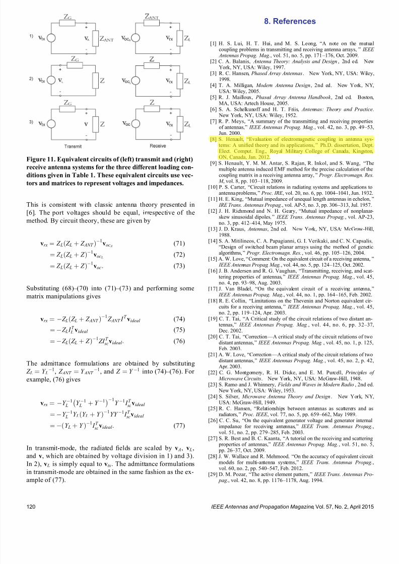
7232019 Unifying the Theory of Mutual Coupling Compensation in Antenna Arrays
httpslidepdfcomreaderfullunifying-the-theory-of-mutual-coupling-compensation-in-antenna-arrays 1719
This is consistent with classic antenna theory presented in
[6] The port voltages should be equal irrespective of the
method By circuit theory these are given by
vrx frac14 Z LethZ L thorn Z ANT THORN1
voc A (71)
frac14 Z LethZ L thorn Z THORN1voc L
(72)
frac14 Z LethZ L thorn Z THORN1voc (73)
Substituting (68) ndash (70) into (71) ndash (73) and performing some
matrix manipulations gives
vrx frac14 Z LethZ L thorn Z ANT THORN1
Z ANT I T videal (74)
frac14 Z L I T L videal (75)
frac14 Z LethZ L thorn Z THORN1ZI T
scvideal (76)
The admittance formulations are obtained by substituting
Z L frac14 Y L1 Z ANT frac14 Y ANT
1 and Z frac14 Y 1 into (74) ndash (76) For
example (76) gives
vrx frac14 Y 1 L Y 1
L thorn Y 1 1
Y 1 I T scvideal
frac14 Y 1 L Y LethY L thorn Y THORN1
YY 1 I T scvideal
frac14 ethY L thorn Y THORN1 I T
scvideal (77)
In transmit-mode the radiated 1047297elds are scaled by v A v L
and v which are obtained by voltage division in 1) and 3)
In 2) v L is simply equal to vtx The admittance formulations
in transmit-mode are obtained in the same fashion as the ex-
ample of (77)
8 References
[1] H S Lui H T Hui and M S Leong ldquoA note on the mutualcoupling problems in transmitting and receiving antenna arraysrdquo IEEE Antennas Propag Mag vol 51 no 5 pp 171 ndash 176 Oct 2009
[2] C A Balanis Antenna Theory Analysis and Design 2nd ed NewYork NY USA Wiley 1997
[3] R C Hansen Phased Array Antennas New York NY USA Wiley1998
[4] T A Milligan Modern Antenna Design 2nd ed New York NYUSA Wiley 2005
[5] R J Mailloux Phased Array Antenna Handbook 2nd ed BostonMA USA Artech House 2005[6] S A Schelkunoff and H T Friis Antennas Theory and Practice
New York NY USA Wiley 1952[7] R P Meys ldquoA summary of the transmitting and receiving properties
of antennasrdquo IEEE Antennas Propag Mag vol 42 no 3 pp 49 ndash 53Jun 2000
[8] S Henault ldquoEvaluation of electromagnetic coupling in antenna sys-tems A uni1047297ed theory and its applicationsrdquo PhD dissertation DeptElect Comput Eng Royal Military College of Canada KingstonON Canada Jan 2012
[9] S Henault Y M M Antar S Rajan R Inkol and S Wang ldquoThemultiple antenna induced EMF method for the precise calculation of thecoupling matrix in a receiving antenna arrayrdquo Progr Electromagn Res M vol 8 pp 103 ndash 118 2009
[10] P S Carter ldquoCircuit relations in radiating systems and applications toantenna problemsrdquo Proc IRE vol 20 no 6 pp 1004 ndash 1041 Jun 1932
[11] H E King ldquoMutual impedance of unequal length antennas in echelonrdquo IRE Trans Antennas Propag vol AP-5 no 3 pp 306 ndash 313 Jul 1957
[12] J H Richmond and N H Geary ldquoMutual impedance of nonplanar-skew sinusoidal dipolesrdquo IEEE Trans Antennas Propag vol AP-23no 3 pp 412 ndash 414 May 1975
[13] J D Kraus Antennas 2nd ed New York NY USA McGraw-Hill1988
[14] S A Mitilineos C A Papagianni G I Verikaki and C N CapsalisldquoDesign of switched beam planar arrays using the method of geneticalgorithmsrdquo Progr Electromagn Res vol 46 pp 105 ndash 126 2004
[15] A W Love ldquoComment On the equivalent circuit of a receiving antennardquo IEEE Antennas Propag Mag vol 44 no 5 pp 124 ndash 125 Oct 2002
[16] J B Andersen and R G Vaughan ldquoTransmitting receiving and scat-tering properties of antennasrdquo IEEE Antennas Propag Mag vol 45no 4 pp 93 ndash 98 Aug 2003
[17] J Van Bladel ldquoOn the equivalent circuit of a receiving antennardquo
IEEE Antennas Propag Mag vol 44 no 1 pp 164 ndash
165 Feb 2002[18] R E Collin ldquoLimitations on the Thevenin and Norton equivalent cir-cuits for a receiving antennardquo IEEE Antennas Propag Mag vol 45no 2 pp 119 ndash 124 Apr 2003
[19] C T Tai ldquoA Critical study of the circuit relations of two distant an-tennasrdquo IEEE Antennas Propag Mag vol 44 no 6 pp 32 ndash 37Dec 2002
[20] C T Tai ldquoCorrection V A critical study of the circuit relations of twodistant antennasrdquo IEEE Antennas Propag Mag vol 45 no 1 p 125Feb 2003
[21] A W Love ldquoCorrection V A critical study of the circuit relations of twodistant antennasrdquo IEEE Antennas Propag Mag vol 45 no 2 p 42Apr 2003
[22] C G Montgomery R H Dicke and E M Purcell Principles of Microwave Circuits New York NY USA McGraw-Hill 1948
[23] S Ramo and J Whinnery Fields and Waves in Modern Radio 2nd ed New York NY USA Wiley 1953
[24] S Silver Microwave Antenna Theory and Design New York NYUSA McGraw-Hill 1949
[25] R C Hansen ldquoRelationships between antennas as scatterers and asradiatorsrdquo Proc IEEE vol 77 no 5 pp 659 ndash 662 May 1989
[26] C C Su ldquoOn the equivalent generator voltage and generator internalimpedance for receiving antennasrdquo IEEE Trans Antennas Propagvol 51 no 2 pp 279 ndash 285 Feb 2003
[27] S R Best and B C Kaanta ldquoA tutorial on the receiving and scattering properties of antennasrdquo IEEE Antennas Propag Mag vol 51 no 5 pp 26 ndash 37 Oct 2009
[28] J W Wallace and R Mehmood ldquoOn the accuracy of equivalent circuit models for multi-antenna systemsrdquo IEEE Trans Antennas Propagvol 60 no 2 pp 540 ndash 547 Feb 2012
[29] D M Pozar ldquoThe active element patternrdquo IEEE Trans Antennas Pro- pag vol 42 no 8 pp 1176 ndash 1178 Aug 1994
Figure 11 Equivalent circuits of (left) transmit and (right)
receive antenna systems for the three different loading con-
ditions given in Table 1 These equivalent circuits use vec-
tors and matrices to represent voltages and impedances
IEEE Antennas and Propagation Magazine Vol 57 No 2 April 2015120
7232019 Unifying the Theory of Mutual Coupling Compensation in Antenna Arrays
httpslidepdfcomreaderfullunifying-the-theory-of-mutual-coupling-compensation-in-antenna-arrays 1819
[30] D F Kelley and W L Stutzman ldquoArray antenna pattern modelingmethods that include mutual coupling effectsrdquo IEEE Trans Antennas Propag vol 41 no 12 pp 1625 ndash 1632 Dec 1993
[31] K Takamizawa ldquoAnalysis of highly coupled wideband antenna arraysusing scattering parameter network modelsrdquo PhD dissertation DeptElect Comput Eng Virginia Polytech Inst State Univ BlacksburgVA USA Dec 2002
[32] D M Pozar ldquoA relation between the active input impedance and theactive element pattern of a phased arrayrdquo IEEE Trans Antennas Propag vol 51 no 9 pp 2486 ndash 2489 Sep 2003
[33] D F Kelley ldquoRelationships between active element patterns and mutual impedance matrices in phased array antennasrdquo in Proc IEEE Int Symp Antennas Propag 2002 pp 524 ndash 527
[34] D F Kelley ldquo
Embedded element patterns and mutual impedancematrices in the terminated phased array environmentrdquo in Proc IEEE Int Symp Antennas Propag 2005 pp 659 ndash 662
[35] R F Harrington ldquoAntenna excitation for maximum gainrdquo IEEE Trans Antennas Propag vol AP-13 no 6 pp 896 ndash 903 Nov 1965
[36] H Rogier and E Bonek ldquoAnalytical spherical-mode-based compensa-tion of mutual coupling in uniform circular arrays for direction-of-arrivalestimationrdquo Int J Electron Commun vol 60 no 3 pp 179 ndash 189Mar 2006
[37] A T De Hoop ldquoThe N-port receiving antenna and its equivalent elec-trical networkrdquo Philips Res Rep vol 30 pp 302 ndash 315 1975
[38] P S Kildal ldquoEquivalent circuits of receive antennas in signal process-ing arraysrdquo Microw Opt Technol Lett vol 21 no 4 pp 244 ndash 246May 1999
[39] K F Warnick B Woestenburg L Belostotski and P Russer ldquoMinimiz-ing the noise penalty due to mutual coupling for a receiving arrayrdquo IEEE Trans Antennas Propag vol 57 no 6 pp 1634 ndash 1644 Jun 2009
[40] R O Schmidt ldquoMultilinear array manifold interpolationrdquo IEEE TransSignal Process vol 40 no 4 pp 857 ndash 866 Apr 1992
[41] A J Weiss and B Friedlander ldquoManifold interpolation for diversely po-larized arraysrdquo Proc Inst Elect Eng V Radar Sonar Navig vol 141no 1 pp 19 ndash 24 Feb 1994
[42] R J Allard and D H Werner ldquoThe model-based parameter estimationof antenna radiation patterns using windowed interpolation and sphericalharmonicsrdquo IEEE Trans Antennas Propag vol 51 no 8 pp 1891 ndash 1906 Aug 2003
[43] M Landmann and G Del Galdo ldquoEf 1047297cient antenna description for MIMO channel modelling and estimationrdquo in Proc 7th Eur ConfWireless Technol Amsterdam The Netherlands 2004 pp 217 ndash 220
[44] G Del Galdo J Lotze M Landmann and M Haardt ldquoModelling and manipulation of polarimetric antenna beam patterns via sphericalharmonicsrdquo in Proc 14th Eur Signal Process Conf Florence ItalySep 2006 pp 1 ndash 5
[45] F Belloni A Richter and V Koivunen ldquo
DoA estimation via manifold separation for arbitrary array structuresrdquo IEEE Trans Signal Processvol 55 no 10 pp 4800 ndash 4810 Oct 2007
[46] H T Hui ldquoDecoupling methods for the mutual coupling effect in an-tenna arrays A reviewrdquo Recent Patents Eng vol 1 no 2 pp 187 ndash 193 Jun 2007
[47] T Su and H Ling ldquoOn modeling mutual coupling in antenna arraysusing the coupling matrixrdquo Microw Opt Technol Lett vol 28 no 4 pp 231 ndash 237 Feb 2001
[48] P Darwood P N Fletcher and G S Hilton ldquoMutual couplingcompensation in small planar array antennasrdquo Proc Inst Elect Eng V
Microw Antennas Propag vol 145 no 1 pp 1 ndash 6 Feb 1998[49] H Steyskal and J S Herd ldquoMutual coupling compensation in small array
antennasrdquo IEEE Trans Antennas Propag vol 38 no 12 pp 1971 ndash 1975 Dec 1990
[50] I J Gupta and A A Ksienski ldquoEffect of mutual coupling on the performance of adaptive arraysrdquo IEEE Trans Antennas Propag
vol AP-31 no 5 pp 785 ndash 791 Sep 1983[51] C C Yeh M L Leou and D R Ucci ldquoBearing estimations with mu-
tual coupling presentrdquo IEEE Trans Antennas Propag vol 37 no 10 pp 1332 ndash 1335 Oct 1989
[52] C Roller and W Wasylkiwskyj ldquoEffects of mutual coupling on super-resolution DF in linear arraysrdquo in Proc IEEE Int Conf AcoustSpeech Signal Process vol 5 1992 pp 257 ndash 260
[53] Z Huang C A Balanis and C R Birtcher ldquoMutual couplingcompensation in UCAs Simulations and experimentrdquo IEEE Trans Antennas Propag vol 54 no 11 pp 3082 ndash 3086 Nov 2006
[54] K C Lee and T H Chu ldquoA circuit model for mutual couplinganalysis of a 1047297nite antenna arrayrdquo IEEE Trans Electromagn Compatvol 38 no 3 pp 483 ndash 489 Aug 1996
[55] K W Lo and T B Vu ldquoSimple S-parameter model for receiving an-tenna arrayrdquo Electron Lett vol 24 no 20 pp 1264 ndash 1266 Sep 1988
[56] K M Pasala and E M Friel ldquoMutual coupling effects and their reduction in wideband direction of arrival estimationrdquo IEEE Trans Aerosp Electron Syst vol 30 no 4 pp 1116 ndash 1122 Apr 1994
[57] R S Adve and T K Sarkar ldquoCompensation for the effects of mutualcoupling on direct data domain adaptive algorithmsrdquo IEEE Trans An-tennas Propag vol 48 no 1 pp 86 ndash 94 Jan 2000
[58] R F Harrington Field Computation by Moment Methods New York NY USA Wiley 1968
[59] J Pierre and M Kaveh ldquoExperimental performance of calibration and direction-1047297nding algorithmsrdquo in Proc IEEE Int Conf Acoust SpeechSignal Process vol 2 Toronto ON Canada Apr 1991 pp 1365 ndash 1368
[60] T Su K Dandekar and H Ling ldquoSimulation of mutual couplingeffect in circular arrays for direction-1047297nding applicationsrdquo Microw
Opt Technol Lett vol 26 no 5 pp 331 ndash
336 Sep 2000[61] K R Dandekar H Ling and G Xu ldquoExperimental study of mutualcoupling compensation in smart antenna applicationsrdquo IEEE TransWireless Commun vol 1 no 3 pp 480 ndash 487 Jul 2002
[62] H T Hui ldquoReducing the mutual coupling effect in adaptive nullingusing a re-de1047297ned mutual impedancerdquo IEEE Microw Wireless Compon Lett vol 12 no 5 pp 178 ndash 180 May 2002
[63] H T Hui ldquoCompensating for the mutual coupling effect in direction1047297nding based on a new calculation method for mutual impedancerdquo IEEE Antennas Wireless Propag Lett vol 2 no 1 pp 26 ndash 29 2003
[64] H T Hui ldquoImproved compensation for the mutual coupling effect ina dipole array for direction 1047297ndingrdquo IEEE Trans Antennas Propagvol 51 no 9 pp 2498 ndash 2503 Sep 2003
[65] H T Hui ldquoA practical approach to compensate for the mutual couplingeffect in an adaptive dipole arrayrdquo IEEE Trans Antennas Propagvol 52 no 5 pp 1262 ndash 1269 May 2004
[66] H T Hui ldquoA new de1047297nition of mutual impedance for application in di-
pole receiving antenna arraysrdquo IEEE Antennas Wireless Propag Lettvol 3 no 1 pp 364 ndash 367 Dec 2004
[67] S Henault and Y M M Antar ldquoWideband analysis of mutual couplingcompensation methodsrdquo Int J Antennas Propag vol 2011 2011Art ID 756 153
[68] B Friedlander and A J Weiss ldquoDirection 1047297nding in the presence of mutual couplingrdquo IEEE Trans Antennas Propag vol 39 no 3 pp 273 ndash 284 Mar 1991
[69] E K L Hung ldquoA critical study of a self-calibrating direction-1047297ndingmethod for arraysrdquo IEEE Trans Signal Process vol 42 no 2 pp 471 ndash 474 Feb 1994
[70] F S Sellone and A Serra ldquoA novel online mutual coupling compen-sation algorithm for uniform and linear arraysrdquo IEEE Trans Signal Process vol 55 no 2 pp 560 ndash 573 Feb 2007
[71] M Lin and L Yang ldquoBlind calibration and DOA estimation with uni-form circular arrays in the presence of mutual couplingrdquo IEEE Anten-
nas Wireless Propag Lett vol 5 no 1 pp 315 ndash
318 Dec 2006[72] D Y Gao B H Wang and Y Guo ldquoComments on lsquoBlind calibrationand DOA estimation with uniform circular arrays in the presence of mutual couplingrsquordquo IEEE Antennas Wireless Propag Lett vol 5 no 1 pp 566 ndash 568 Dec 2006
[73] M Lin and L Yang ldquoReply to the comments on lsquoBlind calibration and DOA estimation with uniform circular arrays in the presence of mutualcouplingrsquordquo IEEE Antennas Wireless Propag Lett vol 5 no 1 pp 568 ndash 569 Dec 2006
[74] Q Bao C C Ko and W Zhi ldquoDOA estimation under unknownmutual coupling and multipathrdquo IEEE Trans Aerosp Electron Systvol 41 no 2 pp 565 ndash 573 Apr 2005
[75] Z Ye and C Liu ldquoOn the resiliency of MUSIC direction 1047297nding against antenna sensor couplingrdquo IEEE Trans Antennas Propag vol 56no 2 pp 371 ndash 380 Feb 2008
[76] Z Ye and C Liu ldquo2-D DOA estimation in the presence of mutualcouplingrdquo IEEE Trans Antennas Propag vol 56 no 10 pp 3150 ndash
3158 Oct 2008[77] Y Zhang Q Wan and A M Huang ldquoLocalization of narrow band
sources in the presence of mutual coupling via sparse solution 1047297ndingrdquo Progr Electromagn Res vol 86 pp 243 ndash 257 2008
[78] T Svantesson ldquoAntennas and propagation from a signal processing perspectiverdquo PhD dissertation Dept Signals Syst Chalmers UnivTechnol Goumlteborg Sweden 2001
[79] S Henault and Y M M Antar ldquoLimitations of online calibrationmethodsrdquo in Proc IEEE Int Symp Antennas Propag Toronto ONCanada Jul 2010 pp 1 ndash 4
[80] I J Gupta et al ldquoAn experimental study of antenna array calibrationrdquo IEEE Trans Antennas Propag vol 51 no 3 pp 664 ndash 667 Mar 2003
[81] C K E Lau R S Adve and T K Sarkar ldquoMinimum norm mutual cou- pling compensation with applications in direction of arrival estimationrdquo IEEE Trans Antennas Propag vol 52 no 8 pp 2034 ndash 2041 Aug 2004
IEEE Antennas and Propagation Magazine Vol 57 No 2 April 2015 121
7232019 Unifying the Theory of Mutual Coupling Compensation in Antenna Arrays
httpslidepdfcomreaderfullunifying-the-theory-of-mutual-coupling-compensation-in-antenna-arrays 1919
[82] Q Y Yuan Q Chen and K Sawaya ldquoAccurate DOA estimation usingarray antenna with arbitrary geometryrdquo IEEE Trans Antennas Propagvol 53 no 4 pp 1352 ndash 1357 Apr 2005
[83] S Henault Y M M Antar S Rajan R Inkol and S Wang ldquoEffectsof mutual coupling on the accuracy of adcock direction 1047297nding systemsrdquo IEEE Trans Aerosp Electron Syst vol 48 no 4 pp 2990 ndash 3005Oct 2012
[84] T Su and H Ling ldquoOn the simultaneous modeling of array mutualcoupling and array-platform interactionsrdquo Microw Opt Technol Lettvol 33 no 3 pp 167 ndash 171 May 2002
[85] A Ferreol E Boyer P Larzabal and M Haardt ldquoOn the introductionof an extended coupling matrix for a 2D bearing estimation with an ex- perimental RF systemrdquo Signal Process vol 87 no 9 pp 2005 ndash 2016
Sep 2007[86] J B Andersen and H H Rasmussen ldquoDecoupling and descatteringnetworks for antennasrdquo IEEE Trans Antennas Propag vol AP-24no 6 pp 841 ndash 846 Nov 1976
[87] M Kragalott M S Kluskens D A Zolnick W M Dorsey and J A Valenzi ldquoA toolset independent hybrid method for calculatingantenna couplingrdquo IEEE Trans Antennas Propag vol 59 no 2 pp 443 ndash 451 Feb 2011
[88] A E H Love ldquoThe integration of equations of propagation of electricwavesrdquo Philos Trans Roy Soc London A Math Phys Sci vol 197 pp 1 ndash 45 1901
[89] S Henault S K Podilchak S M Mikki and Y M M Antar ldquoA meth-odology for mutual coupling estimation and compensation in antennasrdquo IEEE Trans Antennas Propag vol 61 no 3 pp 1119 ndash 1131Mar 2013
[90] S Henault and Y M M Antar ldquoOn the interpolation of radiation pat-terns in the calibration of antenna arraysrdquo in IEEE Int Symp Antennas
Propag Spokane WA USA Jul 2011 pp 1747 ndash 1750[91] S Henault and Y M M Antar ldquoA hybrid approach for antenna array
calibrationrdquo in Proc IEEE Int Symp Antennas Propag SpokaneWA USA Jul 2011 pp 1751 ndash 1754
[92] C Pon ldquoRetrodirective array using the heterodyne techniquerdquo IEEE Trans Antennas Propag vol 12 no 2 pp 176 ndash 180 Mar 1964
[93] A F Kay ldquoComments on self-phasing array antennas and electronicallyadaptive antenna systemsrdquo IEEE Trans Antennas Propag vol AP-12no 6 pp 792 ndash 793 Nov 1964
[94] V F Fusco ldquoResponse of retrodirective array in the presence of multi- ple spatially separated sourcesrdquo IEEE Trans Antennas Propag vol 54no 4 pp 1352 ndash 1354 Apr 2006
[95] NEC-2 Manual Lawrence Livermore National Laboratory LivermoreCA USA 1996
[96] L C Van Atta ldquoElectromagnetic re1047298ectorrdquo US Patent 2 908 002Oct 6 1959
[97] T Larsen ldquo
Re1047298
ector arraysrdquo
IEEE Trans Antennas Propag vol AP-14no 6 pp 689 ndash 693 Nov 1966[98] J Appel-Hansen ldquoA van Atta re1047298ector consisting of half-wave dipolesrdquo
IEEE Trans Antennas Propag vol AP-14 no 6 pp 694 ndash 700 Nov 1966
[99] FEKO-Comprehensive EM Solutions [Online] Available httpwwwfekoinfo
[100] R O Schmidt ldquoMultiple emitter location and signal parameter estima-tionrdquo IEEE Trans Antennas Propag vol AP-34 no 3 pp 276 ndash 280Mar 1986
[101] R O Schmidt and R Franks ldquoMultiple source DF signal processingAn experimental systemrdquo IEEE Trans Antennas Propag vol AP-34no 3 pp 281 ndash 290 Mar 1986
[102] E R Ferrara and T M Parks ldquoDirection 1047297nding with an array of antennas having diverse polarizationsrdquo IEEE Trans Antennas Propagvol AP-31 no 2 pp 231 ndash 236 Mar 1983
Simon Henault received the BEng degreefrom Laval University Queacutebec City QCCanada in 2001 and the MASc and PhDdegrees from the Royal Military College of Canada Kingston ON Canada in 2008 and 2012 respectively all in electrical engineering
Since 1998 he has been with CanadarsquosDepartment of National Defence in variouscapacities including two years as a facultymember with the Royal Military College of Canada and multiple assignments with De-fence Research and Development CanadaHe has expertise in antenna radio frequency
and signal processing systems employed in a variety of electronic warfarespace communication and unmanned aerial vehicle platforms
Dr Henault is a regular Reviewer for several journals and conferences
Yahia M M Antar (Srsquo73 ndash Mrsquo76 ndash SMrsquo85 ndash LFrsquo00) received the BSc (Hons) degree fromAlexandria University Alexandria Egypt in1966 and the MSc and PhD degrees fromthe University of Manitoba Winnipeg MBCanada in 1971 and 1975 respectively all inelectrical engineering
In 1977 he held a Government of Canada
Visiting Fellowship with the Communica-tions Research Centre Ottawa ON Canadawhere he worked with the Space TechnologyDirectorate on communications antennas for satellite systems In May 1979 he joined the
Division of Electrical Engineering National Research Council of CanadaOttawa where he worked on polarization radar applications in remote sens-ing of precipitation radio wave propagation electromagnetic scatteringand radar cross-section investigations In November 1987 he joined thestaff of the Department of Electrical and Computer Engineering Royal Mil-itary College of Canada Kingston ON where he has held the position of Professor since 1990 and is currently the Vice Dean for defense and secu-rity research He has authored or coauthored about 200 journal papersmany chapters in books and about 400 refereed conference papers holdsseveral patents has chaired several national and international conferencesand has given plenary talks at many conferences He has supervised and cosupervised over 80 PhD and MSc theses at the Royal Military Collegeof Canada and at Queenrsquos University Kingston several of which have re-ceived the Governor General of Canada Gold Medal the outstanding PhDthesis of the Division of Applied Science as well as many Best Paper Awardsin major international symposia He served as the Chairman of the Canadian Nationa l Commis sion for Radio Scienc e (CNC URSI 1999 ndash 2008) and the Commission B National Chair (1993 ndash 1999) and held an adjunct ap- pointme nt at the Univer sity of Manito ba and has a cross appoint ment at Queenrsquos University
Dr Antar is a Fellow of the Engineering Institute of Canada and theElectromagnetic Academy He serves as an Associate Editor for the IEEEA NTENNAS AND PROPAGATION MAGAZINE served as an Associate Editor for the IEEE TRANSACTIONS ON A NTENNAS AND PROPAGATION and theIEEE A NTENNAS AND WIRELESS PROPAGATION LETTERS and was a mem- ber of the Editorial Board of the International Journal of RF and MicrowaveComputer-Aided Engineering He served on Natural Sciences and Engineer-ing Research Council of Canada grant selection and strategic grant commit-
tees on Ontario Early Research Awards panels and on review panels for the National Science Foundation In May 2002 he was awarded a Tier 1Canada Research Chair in Electromagnetic Engineering which has been re-newed in 2009 In 2003 he was awarded the Royal Military College of Canada ldquoExcellence in Researchrdquo Prize and the RMCC Class of 1965Teaching Excellence Award in 2012 He was elected by the Council of theInternational Union of Radio Science to the Board as Vice President in Au-gust 2008 and in 2013 and to the IEEE Antennas and Propagation SocietyAdministration Committee in December 2009 On January 31 2011 he wasappointed Member of the Canadian Defence Science Advisory Board He ison the IEEE Antennas and Propagation Society Distinguished LecturersProgram In October 2012 he received the Queenrsquos Diamond Jubilee Medalfrom the Governor General of Canada in recognition of his contribution toCanada He was a recipient of the 2014 IEEE Canada RA Fessenden Silver Medal and the 2015 IEEE Canada J M Ham Outstanding EngineeringEducation Award
7232019 Unifying the Theory of Mutual Coupling Compensation in Antenna Arrays
httpslidepdfcomreaderfullunifying-the-theory-of-mutual-coupling-compensation-in-antenna-arrays 1919
[82] Q Y Yuan Q Chen and K Sawaya ldquoAccurate DOA estimation usingarray antenna with arbitrary geometryrdquo IEEE Trans Antennas Propagvol 53 no 4 pp 1352 ndash 1357 Apr 2005
[83] S Henault Y M M Antar S Rajan R Inkol and S Wang ldquoEffectsof mutual coupling on the accuracy of adcock direction 1047297nding systemsrdquo IEEE Trans Aerosp Electron Syst vol 48 no 4 pp 2990 ndash 3005Oct 2012
[84] T Su and H Ling ldquoOn the simultaneous modeling of array mutualcoupling and array-platform interactionsrdquo Microw Opt Technol Lettvol 33 no 3 pp 167 ndash 171 May 2002
[85] A Ferreol E Boyer P Larzabal and M Haardt ldquoOn the introductionof an extended coupling matrix for a 2D bearing estimation with an ex- perimental RF systemrdquo Signal Process vol 87 no 9 pp 2005 ndash 2016
Sep 2007[86] J B Andersen and H H Rasmussen ldquoDecoupling and descatteringnetworks for antennasrdquo IEEE Trans Antennas Propag vol AP-24no 6 pp 841 ndash 846 Nov 1976
[87] M Kragalott M S Kluskens D A Zolnick W M Dorsey and J A Valenzi ldquoA toolset independent hybrid method for calculatingantenna couplingrdquo IEEE Trans Antennas Propag vol 59 no 2 pp 443 ndash 451 Feb 2011
[88] A E H Love ldquoThe integration of equations of propagation of electricwavesrdquo Philos Trans Roy Soc London A Math Phys Sci vol 197 pp 1 ndash 45 1901
[89] S Henault S K Podilchak S M Mikki and Y M M Antar ldquoA meth-odology for mutual coupling estimation and compensation in antennasrdquo IEEE Trans Antennas Propag vol 61 no 3 pp 1119 ndash 1131Mar 2013
[90] S Henault and Y M M Antar ldquoOn the interpolation of radiation pat-terns in the calibration of antenna arraysrdquo in IEEE Int Symp Antennas
Propag Spokane WA USA Jul 2011 pp 1747 ndash 1750[91] S Henault and Y M M Antar ldquoA hybrid approach for antenna array
calibrationrdquo in Proc IEEE Int Symp Antennas Propag SpokaneWA USA Jul 2011 pp 1751 ndash 1754
[92] C Pon ldquoRetrodirective array using the heterodyne techniquerdquo IEEE Trans Antennas Propag vol 12 no 2 pp 176 ndash 180 Mar 1964
[93] A F Kay ldquoComments on self-phasing array antennas and electronicallyadaptive antenna systemsrdquo IEEE Trans Antennas Propag vol AP-12no 6 pp 792 ndash 793 Nov 1964
[94] V F Fusco ldquoResponse of retrodirective array in the presence of multi- ple spatially separated sourcesrdquo IEEE Trans Antennas Propag vol 54no 4 pp 1352 ndash 1354 Apr 2006
[95] NEC-2 Manual Lawrence Livermore National Laboratory LivermoreCA USA 1996
[96] L C Van Atta ldquoElectromagnetic re1047298ectorrdquo US Patent 2 908 002Oct 6 1959
[97] T Larsen ldquo
Re1047298
ector arraysrdquo
IEEE Trans Antennas Propag vol AP-14no 6 pp 689 ndash 693 Nov 1966[98] J Appel-Hansen ldquoA van Atta re1047298ector consisting of half-wave dipolesrdquo
IEEE Trans Antennas Propag vol AP-14 no 6 pp 694 ndash 700 Nov 1966
[99] FEKO-Comprehensive EM Solutions [Online] Available httpwwwfekoinfo
[100] R O Schmidt ldquoMultiple emitter location and signal parameter estima-tionrdquo IEEE Trans Antennas Propag vol AP-34 no 3 pp 276 ndash 280Mar 1986
[101] R O Schmidt and R Franks ldquoMultiple source DF signal processingAn experimental systemrdquo IEEE Trans Antennas Propag vol AP-34no 3 pp 281 ndash 290 Mar 1986
[102] E R Ferrara and T M Parks ldquoDirection 1047297nding with an array of antennas having diverse polarizationsrdquo IEEE Trans Antennas Propagvol AP-31 no 2 pp 231 ndash 236 Mar 1983
Simon Henault received the BEng degreefrom Laval University Queacutebec City QCCanada in 2001 and the MASc and PhDdegrees from the Royal Military College of Canada Kingston ON Canada in 2008 and 2012 respectively all in electrical engineering
Since 1998 he has been with CanadarsquosDepartment of National Defence in variouscapacities including two years as a facultymember with the Royal Military College of Canada and multiple assignments with De-fence Research and Development CanadaHe has expertise in antenna radio frequency
and signal processing systems employed in a variety of electronic warfarespace communication and unmanned aerial vehicle platforms
Dr Henault is a regular Reviewer for several journals and conferences
Yahia M M Antar (Srsquo73 ndash Mrsquo76 ndash SMrsquo85 ndash LFrsquo00) received the BSc (Hons) degree fromAlexandria University Alexandria Egypt in1966 and the MSc and PhD degrees fromthe University of Manitoba Winnipeg MBCanada in 1971 and 1975 respectively all inelectrical engineering
In 1977 he held a Government of Canada
Visiting Fellowship with the Communica-tions Research Centre Ottawa ON Canadawhere he worked with the Space TechnologyDirectorate on communications antennas for satellite systems In May 1979 he joined the
Division of Electrical Engineering National Research Council of CanadaOttawa where he worked on polarization radar applications in remote sens-ing of precipitation radio wave propagation electromagnetic scatteringand radar cross-section investigations In November 1987 he joined thestaff of the Department of Electrical and Computer Engineering Royal Mil-itary College of Canada Kingston ON where he has held the position of Professor since 1990 and is currently the Vice Dean for defense and secu-rity research He has authored or coauthored about 200 journal papersmany chapters in books and about 400 refereed conference papers holdsseveral patents has chaired several national and international conferencesand has given plenary talks at many conferences He has supervised and cosupervised over 80 PhD and MSc theses at the Royal Military Collegeof Canada and at Queenrsquos University Kingston several of which have re-ceived the Governor General of Canada Gold Medal the outstanding PhDthesis of the Division of Applied Science as well as many Best Paper Awardsin major international symposia He served as the Chairman of the Canadian Nationa l Commis sion for Radio Scienc e (CNC URSI 1999 ndash 2008) and the Commission B National Chair (1993 ndash 1999) and held an adjunct ap- pointme nt at the Univer sity of Manito ba and has a cross appoint ment at Queenrsquos University
Dr Antar is a Fellow of the Engineering Institute of Canada and theElectromagnetic Academy He serves as an Associate Editor for the IEEEA NTENNAS AND PROPAGATION MAGAZINE served as an Associate Editor for the IEEE TRANSACTIONS ON A NTENNAS AND PROPAGATION and theIEEE A NTENNAS AND WIRELESS PROPAGATION LETTERS and was a mem- ber of the Editorial Board of the International Journal of RF and MicrowaveComputer-Aided Engineering He served on Natural Sciences and Engineer-ing Research Council of Canada grant selection and strategic grant commit-
tees on Ontario Early Research Awards panels and on review panels for the National Science Foundation In May 2002 he was awarded a Tier 1Canada Research Chair in Electromagnetic Engineering which has been re-newed in 2009 In 2003 he was awarded the Royal Military College of Canada ldquoExcellence in Researchrdquo Prize and the RMCC Class of 1965Teaching Excellence Award in 2012 He was elected by the Council of theInternational Union of Radio Science to the Board as Vice President in Au-gust 2008 and in 2013 and to the IEEE Antennas and Propagation SocietyAdministration Committee in December 2009 On January 31 2011 he wasappointed Member of the Canadian Defence Science Advisory Board He ison the IEEE Antennas and Propagation Society Distinguished LecturersProgram In October 2012 he received the Queenrsquos Diamond Jubilee Medalfrom the Governor General of Canada in recognition of his contribution toCanada He was a recipient of the 2014 IEEE Canada RA Fessenden Silver Medal and the 2015 IEEE Canada J M Ham Outstanding EngineeringEducation Award