Embed Size (px)
Citation preview
1
1
Unifying RISC and DSP
hyperstone electronics
hyperstone electronics tutorial
E1-32/E1-16and
Software Development Tools
hyperstone electronics tutorial
E1-32/E1-16and
Software Development Tools
2
2
Unifying RISC and DSP
Table Of Contents (1)
❑ Memory• Memory Address Space• Memory Control Register
• Memory Write Access Modes
• Bus Control Register• Connecting DRAM
• Connecting Boot EPROM
• Internal RAM
❑ Peripherals• I/O Bus Access
• UART of hyICE• I/O Address Modes
• I/O Access with C Run-Time Library
3
3
Unifying RISC and DSP
Table Of Contents (2)
❑ Inputs and Outpus• Function Control Register• Interrupt Inputs
• Input Status Register
• Wait Pin INT3• Outputs
• Clock Output
❑ Internal Timer• Timer Prescaler Register, Timer Register, Timer Compare Register
• Timer Prescaler Register and PLL
4
4
Unifying RISC and DSP
Table Of Contents (3)
❑ Runtime Stack• Local Registers and Stack Frame• Runtime Stack
• Register Stack
❑ Privilege States
❑ Trap Entry Table❑ Interrupt-Lock Flag L
❑ Global Registers• Global Registers
• High Global Flag
❑ Supervisor State
❑ Runtime Stack Initialization❑ Power-Down Mode
❑ Sleep Mode
5
5
Unifying RISC and DSP
Table Of Contents (4)
❑ Assembler Example• hyMasm• hyLink
• hyEPROM
❑ Real-Time Operating System hyRTK• Stack-Level Tasks
• Interrupt-Level Tasks• CreateTask
• System Calls for Delaying Tasks
• Guards
• System Calls for accessing System Resources
6
6
Unifying RISC and DSP
Table Of Contents (5)
❑ C Example• hyC• hyLink
• hyAdmin
• hyDebug• hyProf
• hyEPROM
• Boot Loader romboot.hye
❑ DSP Unit• ALU and DSP Unit
• Parallelism ALU - DSP• Example Dot Product
7
7
Unifying RISC and DSP
Memory
❑ Memory• Memory Address Space• Memory Control Register
• Memory Write Access Modes
• Bus Control Register• Connecting DRAM
• Connecting Boot EPROM
• Internal RAM
8
8
Unifying RISC and DSP
Memory Address Space
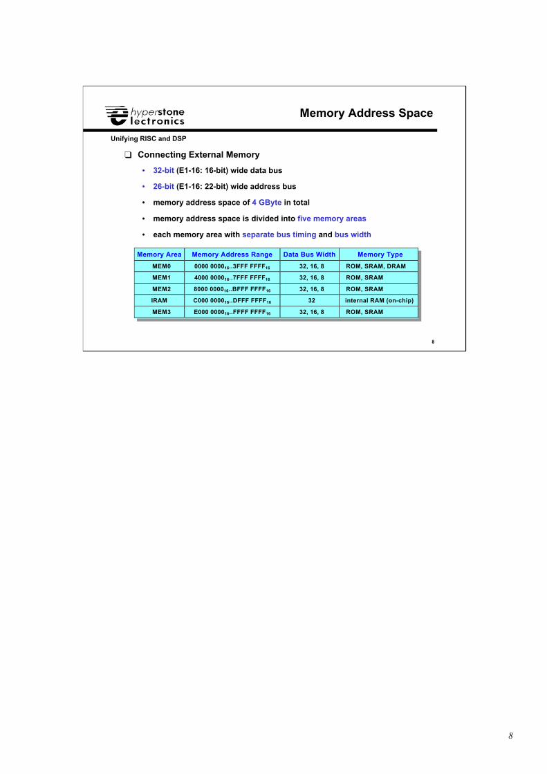
❑ Connecting External Memory
• 32-bit (E1-16: 16-bit) wide data bus
• 26-bit (E1-16: 22-bit) wide address bus
• memory address space of 4 GByte in total
• memory address space is divided into five memory areas
• each memory area with separate bus timing and bus width
Memory Area Memory Address Range Data Bus Width Memory Type
MEM0 0000 000016..3FFF FFFF16 32, 16, 8 ROM, SRAM, DRAM
MEM1 4000 000016..7FFF FFFF16 32, 16, 8 ROM, SRAM
MEM2 8000 000016..BFFF FFFF16 32, 16, 8 ROM, SRAM
IRAM C000 000016..DFFF FFFF16 32 internal RAM (on-chip)
MEM3 E000 000016..FFFF FFFF16 32, 16, 8 ROM, SRAM
9
9
Unifying RISC and DSP
Memory Control Register
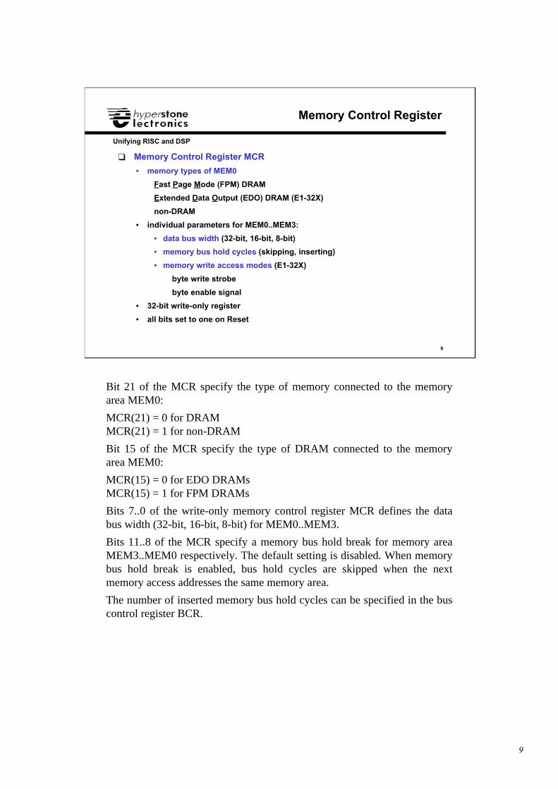
❑ Memory Control Register MCR
• memory types of MEM0
Fast Page Mode (FPM) DRAM
Extended Data Output (EDO) DRAM (E1-32X)
non-DRAM
• individual parameters for MEM0..MEM3:
• data bus width (32-bit, 16-bit, 8-bit)
• memory bus hold cycles (skipping, inserting)
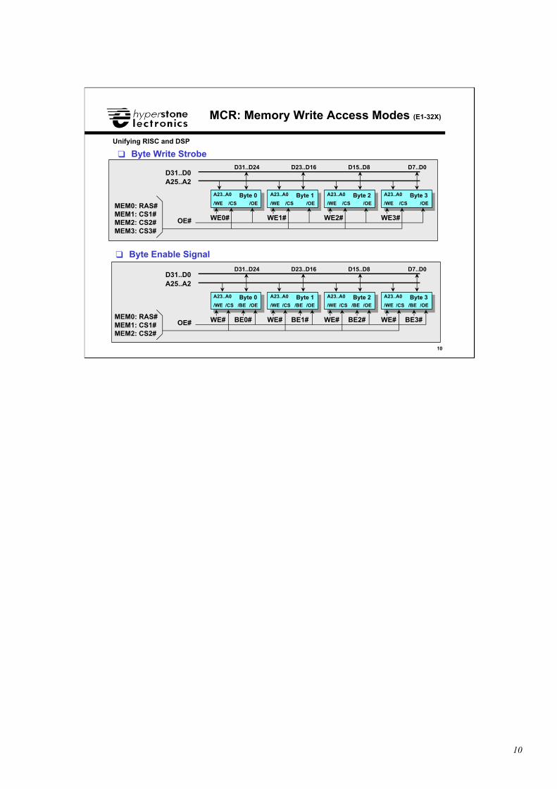
• memory write access modes (E1-32X)
byte write strobe
byte enable signal
• 32-bit write-only register
• all bits set to one on Reset
Bit 21 of the MCR specify the type of memory connected to the memoryarea MEM0:
MCR(21) = 0 for DRAMMCR(21) = 1 for non-DRAM
Bit 15 of the MCR specify the type of DRAM connected to the memoryarea MEM0:
MCR(15) = 0 for EDO DRAMsMCR(15) = 1 for FPM DRAMs
Bits 7..0 of the write-only memory control register MCR defines the databus width (32-bit, 16-bit, 8-bit) for MEM0..MEM3.
Bits 11..8 of the MCR specify a memory bus hold break for memory areaMEM3..MEM0 respectively. The default setting is disabled. When memorybus hold break is enabled, bus hold cycles are skipped when the nextmemory access addresses the same memory area.
The number of inserted memory bus hold cycles can be specified in the buscontrol register BCR.
10
10
Unifying RISC and DSP
MCR: Memory Write Access Modes (E1-32X)
❑ Byte Write Strobe
A25..A2
Byte 0Byte 0
WE0#
D31..D0
Byte 1Byte 1
WE1#
Byte 2Byte 2
WE2#
Byte 3Byte 3
WE3#OE#
❑ Byte Enable Signal
D31..D24 D23..D16 D15..D8 D7..D0
/WE /WE/WE/WE/OE/CS /OE /OE/OE /CS/CS/CSMEM0: RAS#MEM1: CS1#MEM2: CS2#MEM3: CS3#
A23..A0 A23..A0A23..A0A23..A0
A25..A2
Byte 0Byte 0
WE#
D31..D0
Byte 1Byte 1
WE#
Byte 2Byte 2
WE#
Byte 3Byte 3
WE#OE#
D31..D24 D23..D16 D15..D8 D7..D0
/WE /WE/WE/WE/OE/CS /BE /OE /OE/OE /CS /BE/CS /BE/CS /BE
MEM0: RAS#MEM1: CS1#MEM2: CS2#
A23..A0 A23..A0A23..A0A23..A0
BE0# BE1# BE2# BE3#
11
11
Unifying RISC and DSP
Bus Control Register
❑ Bus Control Register BCR
• individual parameters for MEM0..MEM3:
• address bus timing
• data bus timing
• DRAM page size
• DRAM refresh rate
• parity generation and checking
• 32-bit write-only register
• all bits are set to one on Reset
The write-only bus control register BCR defines the parameters (memorybus timing, DRAM page size, DRAM refresh rate, parity generation andchecking) for accessing external memories located in address spacesMEM0..MEM3.
All bits of the MCR and the BCR are set to one on Reset and have to beinitialized according to the external connected memories after Reset. Thesedefault settings represent the slowest memory bus timing. Thus all types ofmemories can operate with this moderate bus timing.
12
12
Unifying RISC and DSP
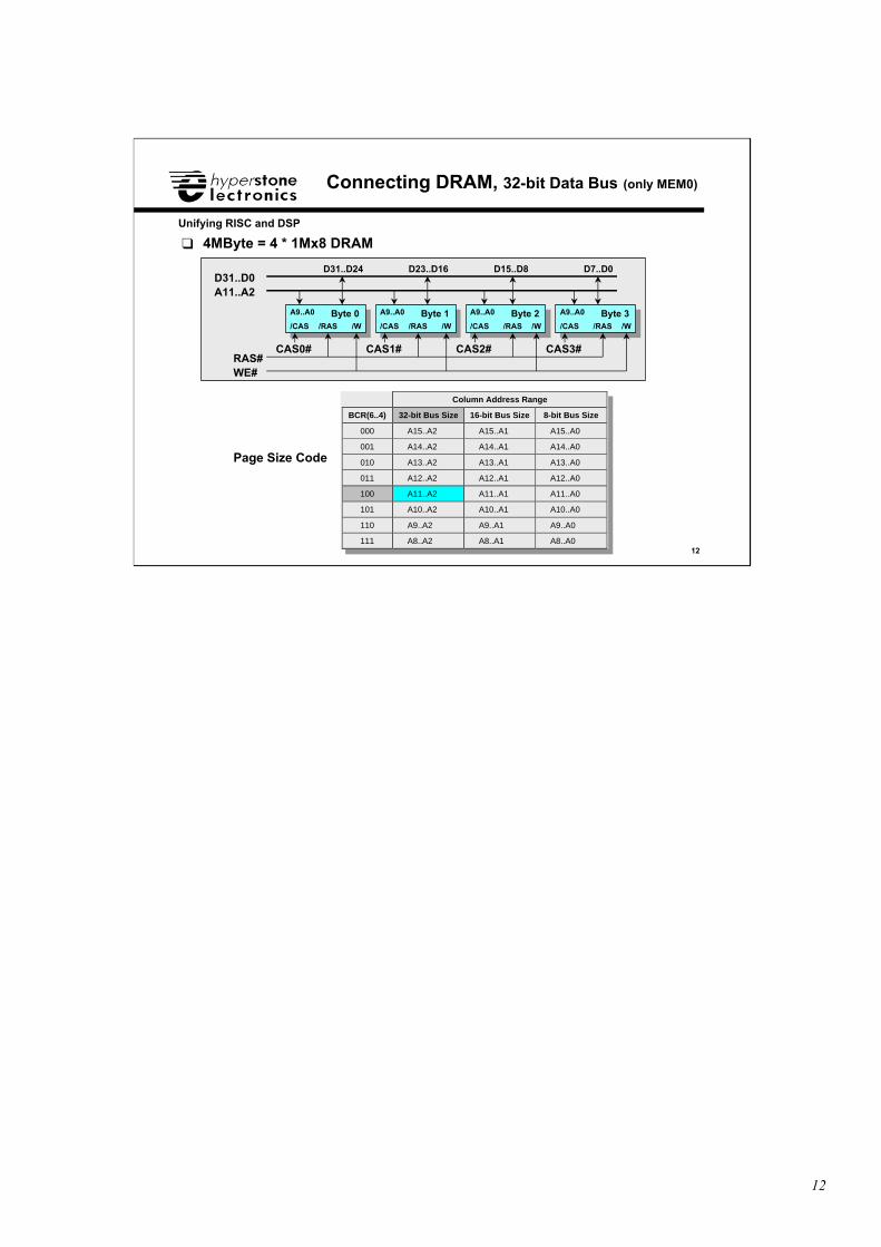
Connecting DRAM, 32-bit Data Bus (only MEM0)
❑ 4MByte = 4 * 1Mx8 DRAM
A11..A2
Byte 0Byte 0
WE#
D31..D0
Byte 1Byte 1 Byte 2Byte 2 Byte 3Byte 3
RAS#
D31..D24 D23..D16 D15..D8 D7..D0
/CAS /CAS/CAS/CAS/W/RAS /W /W/W /RAS/RAS/RAS
A9..A0 A9..A0A9..A0A9..A0
CAS0# CAS3#CAS2#CAS1#
Page Size Code
Column Address Range
BCR(6..4) 32-bit Bus Size 16-bit Bus Size 8-bit Bus Size
000 A15..A2 A15..A1 A15..A0
001 A14..A2 A14..A1 A14..A0
010 A13..A2 A13..A1 A13..A0
011 A12..A2 A12..A1 A12..A0
100 A11..A2 A11..A1 A11..A0
101 A10..A2 A10..A1 A10..A0
110 A9..A2 A9..A1 A9..A0
111 A8..A2 A8..A1 A8..A0
13
13
Unifying RISC and DSP
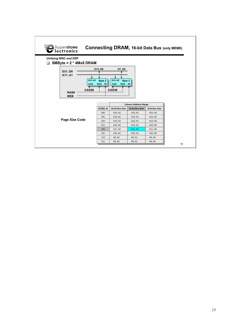
Connecting DRAM, 16-bit Data Bus (only MEM0)
❑ 8MByte = 2 * 4Mx8 DRAM
A11..A1
WE#
D31..D0
Byte 2Byte 2 Byte 3Byte 3
RAS#
D15..D8 D7..D0
/CAS/CAS /W /W/RAS/RAS
A10..A0A10..A0
CAS3#CAS2#
Page Size Code
Column Address Range
BCR(6..4) 32-bit Bus Size 16-bit Bus Size 8-bit Bus Size
000 A15..A2 A15..A1 A15..A0
001 A14..A2 A14..A1 A14..A0
010 A13..A2 A13..A1 A13..A0
011 A12..A2 A12..A1 A12..A0
100 A11..A2 A11..A1 A11..A0
101 A10..A2 A10..A1 A10..A0
110 A9..A2 A9..A1 A9..A0
111 A8..A2 A8..A1 A8..A0
14
14
Unifying RISC and DSP
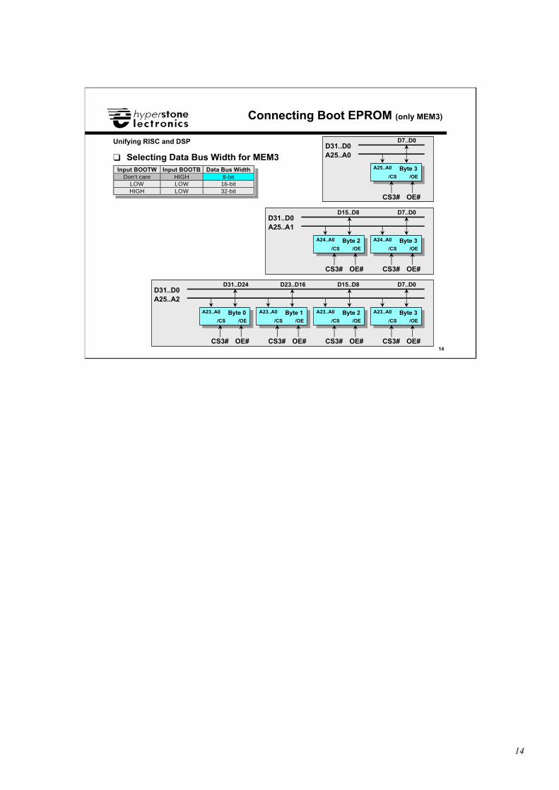
Connecting Boot EPROM (only MEM3)
A25..A0D31..D0
Byte 3Byte 3
D7..D0
/OE/CS
CS3#
A25..A0
OE#
Input BOOTW Input BOOTB Data Bus WidthDon’t care HIGH 8-bit
LOW LOW 16-bitHIGH LOW 32-bit
❑ Selecting Data Bus Width for MEM3
A25..A1D31..D0
Byte 2Byte 2
D15..D8
/OE/CS
CS3#
A24..A0
OE#
Byte 3Byte 3
D7..D0
/OE/CS
CS3#
A24..A0
OE#
A25..A2D31..D0
Byte 0Byte 0
D31..D24
/OE/CS
CS3#
A23..A0
OE#
Byte 1Byte 1
D23..D16
/OE/CS
CS3#
A23..A0
OE#
Byte 2Byte 2
D15..D8
/OE/CS
CS3#
A23..A0
OE#
Byte 3Byte 3
D7..D0
/OE/CS
CS3#
A23..A0
OE#
15
15
Unifying RISC and DSP
Internal RAM
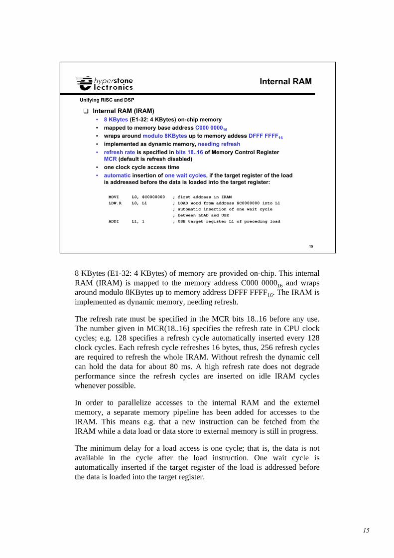
❑ Internal RAM (IRAM)• 8 KBytes (E1-32: 4 KBytes) on-chip memory
• mapped to memory base address C000 000016
• wraps around modulo 8KBytes up to memory addess DFFF FFFF16
• implemented as dynamic memory, needing refresh
• refresh rate is specified in bits 18..16 of Memory Control RegisterMCR (default is refresh disabled)
• one clock cycle access time
• automatic insertion of one wait cycles, if the target register of the loadis addressed before the data is loaded into the target register:
MOVI L0, $C0000000 ; first address in IRAM
LDW.R L0, L1 ; LOAD word from address $C0000000 into L1
; automatic insertion of one wait cycle
; between LOAD and USE
ADDI L1, 1 ; USE target register L1 of preceding load
8 KBytes (E1-32: 4 KBytes) of memory are provided on-chip. This internalRAM (IRAM) is mapped to the memory address C000 000016 and wrapsaround modulo 8KBytes up to memory address DFFF FFFF16. The IRAM isimplemented as dynamic memory, needing refresh.
The refresh rate must be specified in the MCR bits 18..16 before any use.The number given in MCR(18..16) specifies the refresh rate in CPU clockcycles; e.g. 128 specifies a refresh cycle automatically inserted every 128clock cycles. Each refresh cycle refreshes 16 bytes, thus, 256 refresh cyclesare required to refresh the whole IRAM. Without refresh the dynamic cellcan hold the data for about 80 ms. A high refresh rate does not degradeperformance since the refresh cycles are inserted on idle IRAM cycleswhenever possible.
In order to parallelize accesses to the internal RAM and the externelmemory, a separate memory pipeline has been added for accesses to theIRAM. This means e.g. that a new instruction can be fetched from theIRAM while a data load or data store to external memory is still in progress.
The minimum delay for a load access is one cycle; that is, the data is notavailable in the cycle after the load instruction. One wait cycle isautomatically inserted if the target register of the load is addressed beforethe data is loaded into the target register.
16
16
Unifying RISC and DSP
Peripherals
❑ Peripherals• I/O Bus Access• UART of hyICE
• I/O Address Modes
• I/O Access with C Run-Time Library
17
17
Unifying RISC and DSP
I/O Bus Access
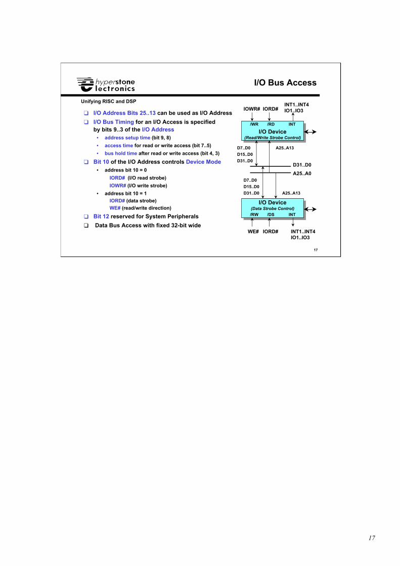
❑ I/O Address Bits 25..13 can be used as I/O Address
❑ I/O Bus Timing for an I/O Access is specifiedby bits 9..3 of the I/O Address
• address setup time (bit 9, 8)
• access time for read or write access (bit 7..5)
• bus hold time after read or write access (bit 4, 3)
❑ Bit 10 of the I/O Address controls Device Mode• address bit 10 = 0
IORD# (I/O read strobe)
IOWR# (I/O write strobe)
• address bit 10 = 1
IORD# (data strobe)
WE# (read/write direction)
❑ Bit 12 reserved for System Peripherals
❑ Data Bus Access with fixed 32-bit wide
I/O Device(Read/Write Strobe Control)
I/O Device(Read/Write Strobe Control)
IOWR#
/WR
INT1..INT4IO1..IO3IORD#
INT/RD
D31..D0
D7..D0
D15..D0
D31..D0
A25..A0
A25..A13
I/O Device(Data Strobe Control)
I/O Device(Data Strobe Control)
WE#
/RW
INT1..INT4IO1..IO3
IORD#
INT/DS
A25..A13
D7..D0
D15..D0
D31..D0
18
18
Unifying RISC and DSP
I/O Bus Access: UART of hyICE (1)
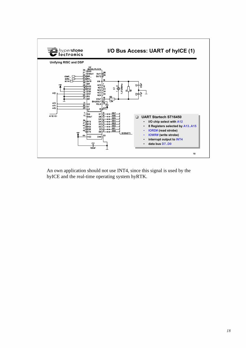
❑ UART Startech ST16450• I/O chip select with A12• 8 Registers selected by A13..A15• IORD# (read strobe)
• IOWR# (write strobe)• interrupt output to INT4
• data bus D7..D0
❑ UART Startech ST16450• I/O chip select with A12• 8 Registers selected by A13..A15• IORD# (read strobe)
• IOWR# (write strobe)• interrupt output to INT4
• data bus D7..D0
An own application should not use INT4, since this signal is used by thehyICE and the real-time operating system hyRTK.
19
19
Unifying RISC and DSP
I/O Bus Access: UART of hyICE (2)
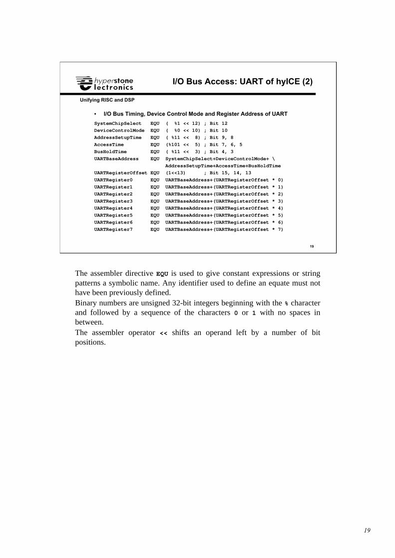
• I/O Bus Timing, Device Control Mode and Register Address of UART
SystemChipSelect EQU ( %1 << 12) ; Bit 12
DeviceControlMode EQU ( %0 << 10) ; Bit 10
AddressSetupTime EQU ( %11 << 8) ; Bit 9, 8
AccessTime EQU (%101 << 5) ; Bit 7, 6, 5
BusHoldTime EQU ( %11 << 3) ; Bit 4, 3
UARTBaseAddress EQU SystemChipSelect+DeviceControlMode+ \
AddressSetupTime+AccessTime+BusHoldTime
UARTRegisterOffset EQU (1<<13) ; Bit 15, 14, 13
UARTRegister0 EQU UARTBaseAddress+(UARTRegisterOffset * 0)
UARTRegister1 EQU UARTBaseAddress+(UARTRegisterOffset * 1)
UARTRegister2 EQU UARTBaseAddress+(UARTRegisterOffset * 2)
UARTRegister3 EQU UARTBaseAddress+(UARTRegisterOffset * 3)
UARTRegister4 EQU UARTBaseAddress+(UARTRegisterOffset * 4)
UARTRegister5 EQU UARTBaseAddress+(UARTRegisterOffset * 5)
UARTRegister6 EQU UARTBaseAddress+(UARTRegisterOffset * 6)
UARTRegister7 EQU UARTBaseAddress+(UARTRegisterOffset * 7)
The assembler directive EQU is used to give constant expressions or stringpatterns a symbolic name. Any identifier used to define an equate must nothave been previously defined.Binary numbers are unsigned 32-bit integers beginning with the % characterand followed by a sequence of the characters 0 or 1 with no spaces inbetween.The assembler operator << shifts an operand left by a number of bitpositions.
20
20
Unifying RISC and DSP
I/O Absolute Address Mode
❑ I/O Absolute Address ModeNotation load instruction: LDx.IOA 0, Rs, dis
Notation store instruction: STx.IOA 0, Rs, dis
Data Type x is with: W: word; D: double-word;
• Absolute addressing of peripheral devicesLDW.IOA 0, L1, UARTRegister0 ; load word from UART reg. 0 to L1
LDW.IOA 0, L1, UARTRegister1 ; load word from UART reg. 1 to L1
LDW.IOA 0, L1, UARTRegister2 ; load word from UART reg. 2 to L1
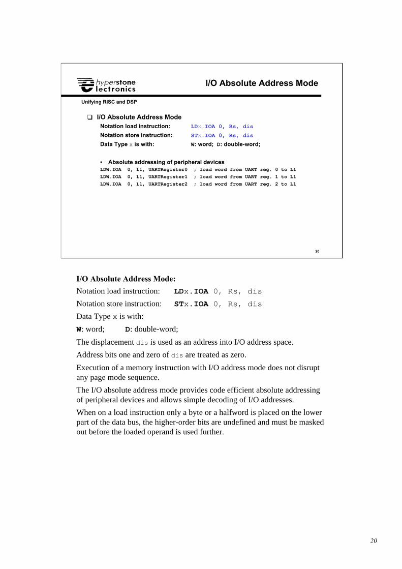
I/O Absolute Address Mode:
Notation load instruction: LDx.IOA 0, Rs, dis
Notation store instruction: STx.IOA 0, Rs, dis
Data Type x is with:
W: word; D: double-word;
The displacement dis is used as an address into I/O address space.
Address bits one and zero of dis are treated as zero.
Execution of a memory instruction with I/O address mode does not disruptany page mode sequence.
The I/O absolute address mode provides code efficient absolute addressingof peripheral devices and allows simple decoding of I/O addresses.
When on a load instruction only a byte or a halfword is placed on the lowerpart of the data bus, the higher-order bits are undefined and must be maskedout before the loaded operand is used further.
21
21
Unifying RISC and DSP
I/O Displacement Address Mode
❑ I/O Displacement Address ModeNotation load instruction: LDx.IOD Rd, Rs, dis
Notation store instruction: STx.IOD Rd, Rs, dis
Data Type x is with: W: word; D: double-word;
• Dynamic addressing of peripheral devicesMOVI L0, UARTRegister0 ; L0 = address of UART reg. 0
LDW.IOD L0, L1, 0 ; load word from UART reg. 0 to L1
ADDI L0, UARTRegisterOffset ; L0 = L0 + offset to next UART reg
LDW.IOD L0, L1, 0 ; load word from UART reg. 1 to L1
ADDI L0, UARTRegisterOffset ; L0 = L0 + offset to next UART reg
LDW.IOD L0, L1, 0 ; load word from UART reg. 2 to L1
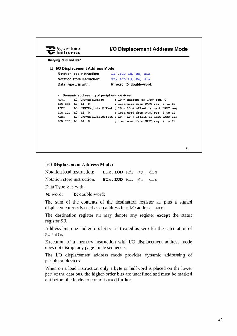
I/O Displacement Address Mode:
Notation load instruction: LDx.IOD Rd, Rs, dis
Notation store instruction: STx.IOD Rd, Rs, dis
Data Type x is with:
W: word; D: double-word;
The sum of the contents of the destination register Rd plus a signeddisplacement dis is used as an address into I/O address space.
The destination register Rd may denote any register except the statusregister SR.
Address bits one and zero of dis are treated as zero for the calculation ofRd + dis.
Execution of a memory instruction with I/O displacement address modedoes not disrupt any page mode sequence.
The I/O displacement address mode provides dynamic addressing ofperipheral devices.
When on a load instruction only a byte or halfword is placed on the lowerpart of the data bus, the higher-order bits are undefined and must be maskedout before the loaded operand is used further.
22
22
Unifying RISC and DSP
C Run-Time Library: inpw()
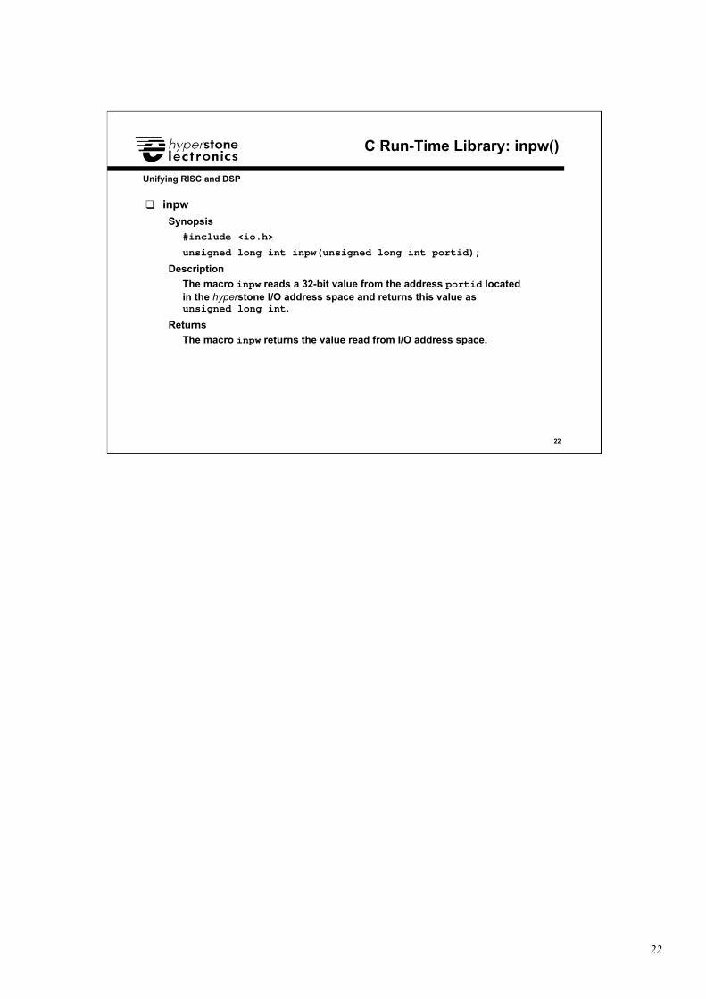
❑ inpw
Synopsis
#include <io.h>
unsigned long int inpw(unsigned long int portid);
Description
The macro inpw reads a 32-bit value from the address portid locatedin the hyperstone I/O address space and returns this value asunsigned long int.
Returns
The macro inpw returns the value read from I/O address space.
23
23
Unifying RISC and DSP
C Run-Time Library: outpw()
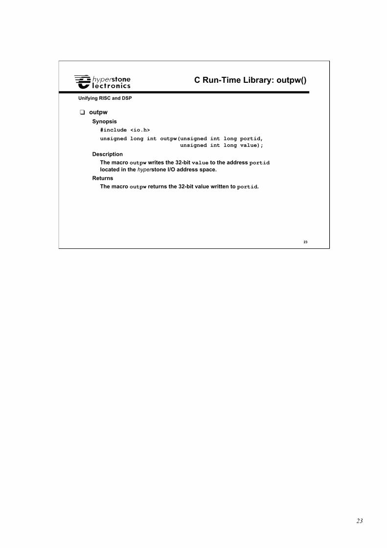
❑ outpw
Synopsis
#include <io.h>
unsigned long int outpw(unsigned int long portid, unsigned int long value);
Description
The macro outpw writes the 32-bit value to the address portidlocated in the hyperstone I/O address space.
Returns
The macro outpw returns the 32-bit value written to portid.

24
24
Unifying RISC and DSP
Inputs and Outputs
❑ Inputs and Outpus• Function Control Register• Interrupt Inputs
• Input Status Register
• Wait Pin INT3• Outputs
• Clock Output
25
25
Unifying RISC and DSP
Interrupts and Function Control Register
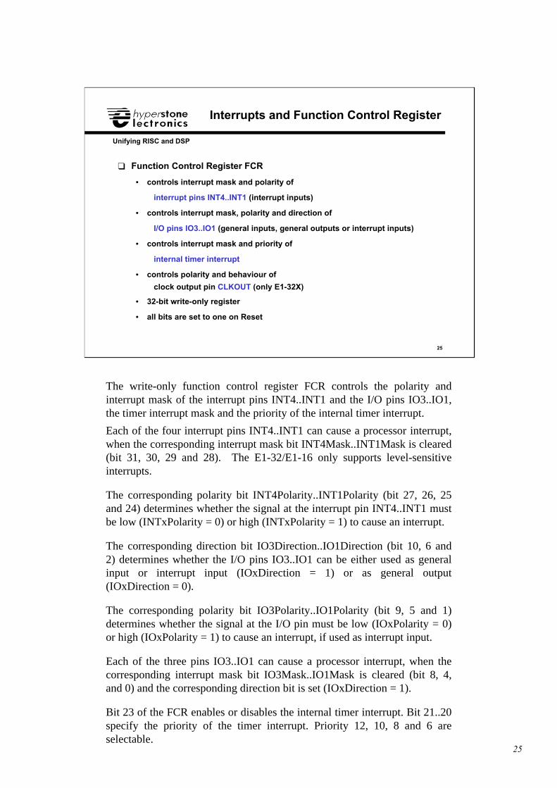
❑ Function Control Register FCR
• controls interrupt mask and polarity of
interrupt pins INT4..INT1 (interrupt inputs)
• controls interrupt mask, polarity and direction of
I/O pins IO3..IO1 (general inputs, general outputs or interrupt inputs)
• controls interrupt mask and priority of
internal timer interrupt
• controls polarity and behaviour of
clock output pin CLKOUT (only E1-32X)
• 32-bit write-only register
• all bits are set to one on Reset
The write-only function control register FCR controls the polarity andinterrupt mask of the interrupt pins INT4..INT1 and the I/O pins IO3..IO1,the timer interrupt mask and the priority of the internal timer interrupt.
Each of the four interrupt pins INT4..INT1 can cause a processor interrupt,when the corresponding interrupt mask bit INT4Mask..INT1Mask is cleared(bit 31, 30, 29 and 28). The E1-32/E1-16 only supports level-sensitiveinterrupts.
The corresponding polarity bit INT4Polarity..INT1Polarity (bit 27, 26, 25and 24) determines whether the signal at the interrupt pin INT4..INT1 mustbe low (INTxPolarity = 0) or high (INTxPolarity = 1) to cause an interrupt.
The corresponding direction bit IO3Direction..IO1Direction (bit 10, 6 and2) determines whether the I/O pins IO3..IO1 can be either used as generalinput or interrupt input (IOxDirection = 1) or as general output(IOxDirection = 0).
The corresponding polarity bit IO3Polarity..IO1Polarity (bit 9, 5 and 1)determines whether the signal at the I/O pin must be low (IOxPolarity = 0)or high (IOxPolarity = 1) to cause an interrupt, if used as interrupt input.
Each of the three pins IO3..IO1 can cause a processor interrupt, when thecorresponding interrupt mask bit IO3Mask..IO1Mask is cleared (bit 8, 4,and 0) and the corresponding direction bit is set (IOxDirection = 1).
Bit 23 of the FCR enables or disables the internal timer interrupt. Bit 21..20specify the priority of the timer interrupt. Priority 12, 10, 8 and 6 areselectable.
26
26
Unifying RISC and DSP
FCR: Interrupt Inputs INT4..INT1, IO3..IO1
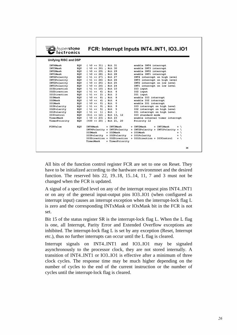
INT4Mask EQU ( %0 << 31) ; Bit 31 enable INT4 interruptINT3Mask EQU ( %0 << 30) ; Bit 30 enable INT3 interruptINT2Mask EQU ( %0 << 29) ; Bit 29 enable INT2 interruptINT1Mask EQU ( %0 << 28) ; Bit 28 enable INT1 interruptINT4Polarity EQU ( %1 << 27) ; Bit 27 INT4 interrupt on high levelINT3Polarity EQU ( %1 << 26) ; Bit 26 INT3 interrupt on high levelINT2Polarity EQU ( %0 << 25) ; Bit 25 INT2 interrupt on low levelINT1Polarity EQU ( %0 << 24) ; Bit 24 INT1 interrupt on low levelIO3Direction EQU ( %1 << 10) ; Bit 10 IO3 inputIO2Direction EQU ( %1 << 6) ; Bit 6 IO2 inputIO1Direction EQU ( %1 << 2) ; Bit 2 IO1 inputIO3Mask EQU ( %0 << 8) ; Bit 8 enable IO3 interruptIO2Mask EQU ( %0 << 4) ; Bit 4 enable IO2 interruptIO1Mask EQU ( %0 << 0) ; Bit 0 enable IO1 interruptIO3Polarity EQU ( %1 << 9) ; Bit 9 IO3 interrupt on high levelIO2Polarity EQU ( %1 << 5) ; Bit 5 IO2 interrupt on high levelIO1Polarity EQU ( %1 << 1) ; Bit 1 IO1 interrupt on high levelIO3Control EQU (%11 << 12) ; Bit 13, 12 IO3 standard modeTimerMask EQU ( %0 << 23) ; Bit 23 enable internal timer interruptTimerPriority EQU (%00 << 20) ; Bit 21, 20 Priority 12
FCRValue EQU INT4Mask + INT3Mask + INT2Mask + INT1Mask + \ INT4Polarity + INT3Polarity + INT2Polarity + INT1Polarity + \ IO3Mask + IO2Mask + IO1Mask + \ IO3Polarity + IO2Polarity + IO1Polarity + \ IO3Direction + IO2Direction + IO1Direction + IO3Control + \ TimerMask + TimerPriority
All bits of the function control register FCR are set to one on Reset. Theyhave to be initialized according to the hardware environmnet and the desiredfunction. The reserved bits 22, 19..18, 15..14, 11, 7 and 3 must not bechanged when the FCR is updated.
A signal of a specified level on any of the interrupt request pins INT4..INT1or on any of the general input-output pins IO3..IO1 (when configured asinterrupt input) causes an interrupt exception when the interrupt-lock flag Lis zero and the corresponding INTxMask or IOxMask bit in the FCR is notset.
Bit 15 of the status register SR is the interrupt-lock flag L. When the L flagis one, all Interrupt, Parity Error and Extended Overflow exceptions areinhibited. The interrupt-lock flag L is set by any exception (Reset, Interruptetc.), thus no further interrupts can occur until the L flag is cleared.
Interrupt signals on INT4..INT1 and IO3..IO1 may be signaledasynchronously to the processor clock, they are not stored internally. Atransition of INT4..INT1 or IO3..IO1 is effective after a minimum of threeclock cycles. The response time may be much higher depending on thenumber of cycles to the end of the current instruction or the number ofcycles until the interrupt-lock flag is cleared.
27
27
Unifying RISC and DSP
Input Status Register
❑ Input Status Register ISR
• Bits 6..4 reflects input level at pins IO3..IO1
• Bits 3..0 reflects input level at pins INT4..INT1
• input levels are not affected by the polarity bits in FCR
• input levels reflect always true signal at corresponding pin
• “1” signals high level at input level
• 32-bit read-only register
The read-only input status register ISR reflects the input level at the pinsIO3..IO1 as well as the input levels at the interrupt pins INT4..INT1.
The input levels are not affected by the polarity bits in the FCR register,they reflect always the true signal at the corresponding pins with a latencyof 2..3 clock cycles, a “1” signals high level.
Bits 6..4 reflects the input level at the pins IO3..IO1.
The signal level of INT4..INT1 can be inspected in bit 3..0 of the ISR. Thus,with the corresponding INTxMask bit set, INT4..INT1 can be used just asinput signals.
28
28
Unifying RISC and DSP
Minimum Access TimeAddress Setup Time Bus Hold Time
INT3 ignored
AdditionalAccess Time
Total Access Time
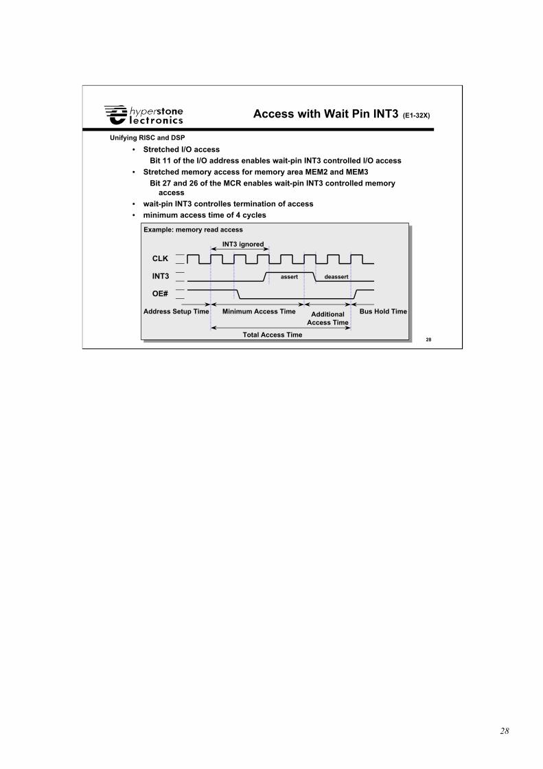
Access with Wait Pin INT3 (E1-32X)
• Stretched I/O accessBit 11 of the I/O address enables wait-pin INT3 controlled I/O access
• Stretched memory access for memory area MEM2 and MEM3
Bit 27 and 26 of the MCR enables wait-pin INT3 controlled memoryaccess
• wait-pin INT3 controlles termination of access• minimum access time of 4 cycles
INT3
CLK
OE#
assert deassert
Example: memory read access
29
29
Unifying RISC and DSP
FCR: Outputs IO3..IO1
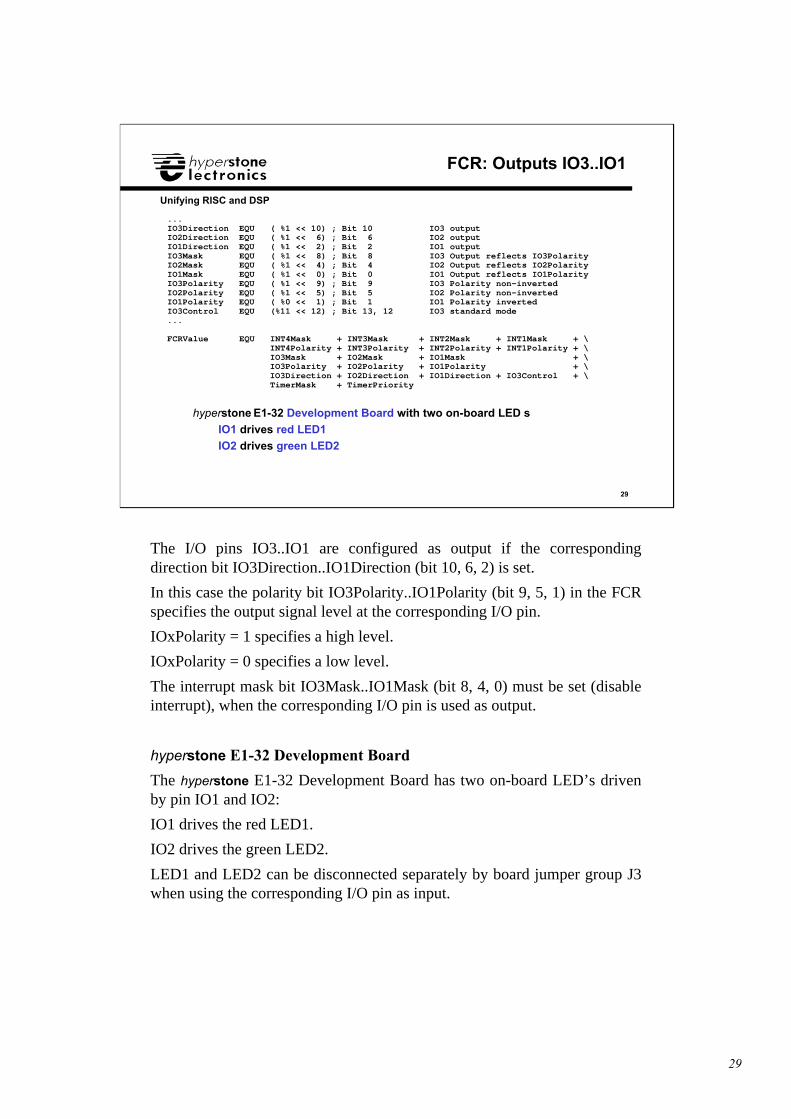
...IO3Direction EQU ( %1 << 10) ; Bit 10 IO3 outputIO2Direction EQU ( %1 << 6) ; Bit 6 IO2 outputIO1Direction EQU ( %1 << 2) ; Bit 2 IO1 outputIO3Mask EQU ( %1 << 8) ; Bit 8 IO3 Output reflects IO3PolarityIO2Mask EQU ( %1 << 4) ; Bit 4 IO2 Output reflects IO2PolarityIO1Mask EQU ( %1 << 0) ; Bit 0 IO1 Output reflects IO1PolarityIO3Polarity EQU ( %1 << 9) ; Bit 9 IO3 Polarity non-invertedIO2Polarity EQU ( %1 << 5) ; Bit 5 IO2 Polarity non-invertedIO1Polarity EQU ( %0 << 1) ; Bit 1 IO1 Polarity invertedIO3Control EQU (%11 << 12) ; Bit 13, 12 IO3 standard mode...
FCRValue EQU INT4Mask + INT3Mask + INT2Mask + INT1Mask + \ INT4Polarity + INT3Polarity + INT2Polarity + INT1Polarity + \ IO3Mask + IO2Mask + IO1Mask + \ IO3Polarity + IO2Polarity + IO1Polarity + \ IO3Direction + IO2Direction + IO1Direction + IO3Control + \ TimerMask + TimerPriority
hyperstone E1-32 Development Board with two on-board LED’s
IO1 drives red LED1
IO2 drives green LED2
The I/O pins IO3..IO1 are configured as output if the correspondingdirection bit IO3Direction..IO1Direction (bit 10, 6, 2) is set.
In this case the polarity bit IO3Polarity..IO1Polarity (bit 9, 5, 1) in the FCRspecifies the output signal level at the corresponding I/O pin.
IOxPolarity = 1 specifies a high level.
IOxPolarity = 0 specifies a low level.
The interrupt mask bit IO3Mask..IO1Mask (bit 8, 4, 0) must be set (disableinterrupt), when the corresponding I/O pin is used as output.
hyperstone E1-32 Development Board
The hyperstone E1-32 Development Board has two on-board LED’s drivenby pin IO1 and IO2:
IO1 drives the red LED1.
IO2 drives the green LED2.
LED1 and LED2 can be disconnected separately by board jumper group J3when using the corresponding I/O pin as input.
30
30
Unifying RISC and DSP
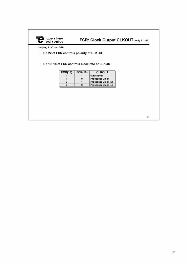
FCR: Clock Output CLKOUT (only E1-32X)
❑ Bit 22 of FCR controls polarity of CLKOUT
❑ Bit 19..18 of FCR controls clock rate of CLKOUT
FCR(19) FCR(18) CLKOUT1 1 static level1 0 Processor Clock0 1 Processor Clock : 20 0 Processor Clock : 4
31
31
Unifying RISC and DSP
Internal Timer
❑ Internal Timer• Timer Prescaler Register TPR• Timer Register TR
• Timer Compare Register TCR
• Timer Prescaler Register TPR and PLL
32
32
Unifying RISC and DSP
Internal Timer
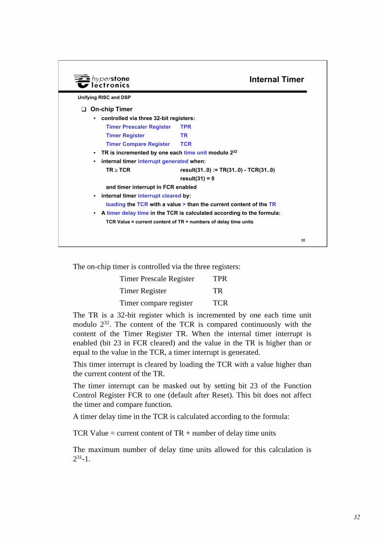
❑ On-chip Timer• controlled via three 32-bit registers:
Timer Prescaler Register TPR
Timer Register TR
Timer Compare Register TCR
• TR is incremented by one each time unit modulo 232
• internal timer interrupt generated when:
TR ≥ ≥ TCR ⇒⇒ result(31..0) := TR(31..0) - TCR(31..0)
result(31) = 0
and timer interrupt in FCR enabled
• internal timer interrupt cleared by:
loading the TCR with a value > than the current content of the TR
• A timer delay time in the TCR is calculated according to the formula:
TCR Value = current content of TR + numbers of delay time units
The on-chip timer is controlled via the three registers:
Timer Prescale Register TPR
Timer Register TR
Timer compare register TCR
The TR is a 32-bit register which is incremented by one each time unitmodulo 232. The content of the TCR is compared continuously with thecontent of the Timer Register TR. When the internal timer interrupt isenabled (bit 23 in FCR cleared) and the value in the TR is higher than orequal to the value in the TCR, a timer interrupt is generated.
This timer interrupt is cleared by loading the TCR with a value higher thanthe current content of the TR.
The timer interrupt can be masked out by setting bit 23 of the FunctionControl Register FCR to one (default after Reset). This bit does not affectthe timer and compare function.
A timer delay time in the TCR is calculated according to the formula:
TCR Value = current content of TR + number of delay time units
The maximum number of delay time units allowed for this calculation is231-1.
33
33
Unifying RISC and DSP
Timer Prescaler Register (1)
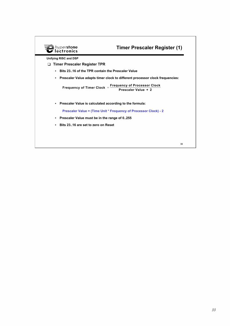
❑ Timer Prescaler Register TPR
• Bits 23..16 of the TPR contain the Prescaler Value
• Prescaler Value adapts timer clock to different processor clock frequencies:
• Prescaler Value is calculated according to the formula:
Prescaler Value = (Time Unit * Frequency of Processor Clock) - 2
• Prescaler Value must be in the range of 0..255
• Bits 23..16 are set to zero on Reset
Frequency of Timer Clock Frequency of Processor Clock
Prescaler Value + 2=
34
34
Unifying RISC and DSP
Timer Prescaler Register (2)
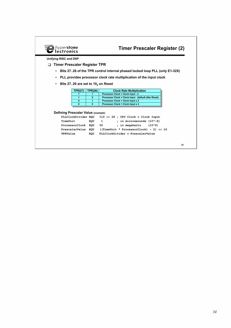
❑ Timer Prescaler Register TPR
• Bits 27..26 of the TPR control internal phased locked loop PLL (only E1-32X)
• PLL provides processor clock rate multiplication of the input clock
• Bits 27..26 are set to 102 on Reset
TPR(27) TPR(26) Clock Rate Multiplication1 1 Processor Clock = Clock Input : 21 0 Processor Clock = Clock Input (default after Reset)0 1 Processor Clock = Clock Input x 20 0 Processor Clock = Clock Input x 4
Defining Prescaler Value (example)
PLLClockDivider EQU %10 << 26 ; CPU Clock = Clock Input
TimeUnit EQU 1 ; in microseconds (10^-6)
ProcessorClock EQU 50 ; in megahertz (10^6)
PrescalerValue EQU ((TimeUnit * ProcessorClock) - 2) << 16
TPRValue EQU PLLClockDivider + PrescalerValue
35
35
Unifying RISC and DSP
Runtime Stack
❑ Runtime Stack• Local Registers and Stack Frame• Runtime Stack
• Register Stack
36
36
Unifying RISC and DSP
Local Registers and Stack Frame
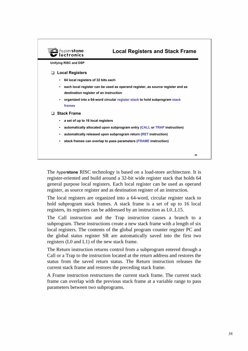
❑ Local Registers
• 64 local registers of 32 bits each
• each local register can be used as operand register, as source register and as
destination register of an instruction
• organized into a 64-word circular register stack to hold subprogram stack
frames
❑ Stack Frame
• a set of up to 16 local registers
• automatically allocated upon subprogram entry (CALL or TRAP instruction)
• automatically released upon subprogram return (RET instruction)
• stack frames can overlap to pass parameters (FRAME instruction)
The hyperstone RISC technology is based on a load-store architecture. It isregister-oriented and build around a 32-bit wide register stack that holds 64general purpose local registers. Each local register can be used as operandregister, as source register and as destination register of an instruction.
The local registers are organized into a 64-word, circular register stack tohold subprogram stack frames. A stack frame is a set of up to 16 localregisters, its registers can be addressed by an instruction as L0..L15.
The Call instruction and the Trap instruction causes a branch to asubprogram. These instructions create a new stack frame with a length of sixlocal registers. The contents of the global program counter register PC andthe global status register SR are automatically saved into the first tworegisters (L0 and L1) of the new stack frame.
The Return instruction returns control from a subprogram entered through aCall or a Trap to the instruction located at the return address and restores thestatus from the saved return status. The Return instruction releases thecurrent stack frame and restores the preceding stack frame.
A Frame instruction restructures the current stack frame. The current stackframe can overlap with the previous stack frame at a variable range to passparameters between two subprograms.
37
37
Unifying RISC and DSP
Runtime Stack (1)
❑ Runtime Stack
• divided into a memory part (hardware stack) and a register part (register
stack)
❑ Register Part of Runtime Stack (register stack)
• holds most recent stack frames
• current stack frame is always kept in the register part of the stack
• frame pointer FP points to the first register of the current stack frame
(addressed as local register L0)
• frame length FL indicates the number of registers (maximum 16) assigned
to the current stack frame
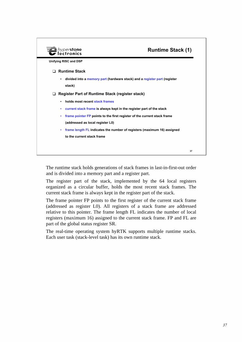
The runtime stack holds generations of stack frames in last-in-first-out orderand is divided into a memory part and a register part.
The register part of the stack, implemented by the 64 local registersorganized as a circular buffer, holds the most recent stack frames. Thecurrent stack frame is always kept in the register part of the stack.
The frame pointer FP points to the first register of the current stack frame(addressed as register L0). All registers of a stack frame are addressedrelative to this pointer. The frame length FL indicates the number of localregisters (maximum 16) assigned to the current stack frame. FP and FL arepart of the global status register SR.
The real-time operating system hyRTK supports multiple runtime stacks.Each user task (stack-level task) has its own runtime stack.
38
38
Unifying RISC and DSP
Runtime Stack (2)
❑ Memory Part of Runtime Stack (hardware stack)
• stack frames are pushed to the memory part of the runtime stack, if the
register stack overflows
• stack frames are popped from the memory part of the runtime stack, if the
register stack underflows
• overflow and underflow of the register stack is managed automatically
• global stack pointer register SP contains the address of the first free
memory location + 4 in which the first local register would be saved by a
push operation
• global upper stack bound register UB guards the memory part of the
runtime stack
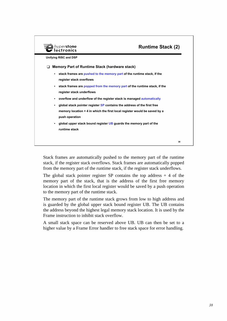
Stack frames are automatically pushed to the memory part of the runtimestack, if the register stack overflows. Stack frames are automatically poppedfrom the memory part of the runtime stack, if the register stack underflows.
The global stack pointer register SP contains the top address + 4 of thememory part of the stack, that is the address of the first free memorylocation in which the first local register would be saved by a push operationto the memory part of the runtime stack.
The memory part of the runtime stack grows from low to high address andis guarded by the global upper stack bound register UB. The UB containsthe address beyond the highest legal memory stack location. It is used by theFrame instruction to inhibit stack overflow.
A small stack space can be reserved above UB. UB can then be set to ahigher value by a Frame Error handler to free stack space for error handling.
39
39
Unifying RISC and DSP
Register Stack (1)
A: FRAME L9, L0 ; set frame length FL = 9
:
code of function A : ; L7 and L8 contain parameters to pass B CALL L9, 0, B ; call function B : code of function A
: RET PC, L0 ; return to function calling A, restore frame
B: FRAME L11, L2 ; set frame length FL = 11, decrement FP by 2 : ; passed parameter1 can now be addressed in L0 : ; passed parameter2 can now be addressed in L1 : code of function B : RET PC, L2 ; return to function A, frame A is restored by ; copying return PC and return SR in L2 and L3 ; of frame B to PC and SR
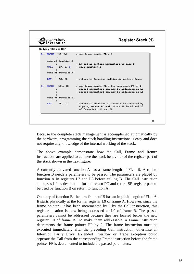
Because the complete stack management is accomplished automatically bythe hardware, programming the stack handling instructions is easy and doesnot require any knowledge of the internal working of the stack.
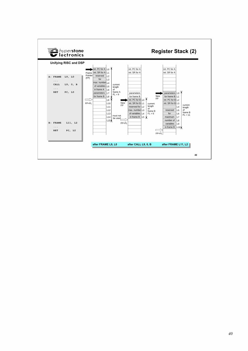
The above example demonstrate how the Call, Frame and Returninstructions are applied to achieve the stack behaviour of the register part ofthe stack shown in the next figure.
A currently activated function A has a frame length of FL = 9. A call tofunction B needs 2 parameters to be passed. The parameters are placed byfunction A in registers L7 and L8 before calling B. The Call instructionaddresses L9 as destination for the return PC and return SR register pair tobe used by function B on return to function A.
On entry of function B, the new frame of B has an implicit length of FL = 6.It starts physically at the former register L9 of frame A. However, since theframe pointer FP has been incremented by 9 by the Call instruction, thisregister location is now being addressed as L0 of frame B. The passedparameters cannot be addressed because they are located below the newregister L0 of frame B. To make them addressable, a Frame instructiondecrements the frame pointer FP by 2. The frame instruction must beexecuted immediately after the preceding Call instruction, otherwise anInterrupt, Parity Error, Extended Overflow or Trace exception couldseperate the Call from the corresponding Frame instruction before the framepointer FP is decremented to include the passed parameters.
40
40
Unifying RISC and DSP
Register Stack (2)
A: FRAME L9, L0
...
CALL L9, 0, B
...
RET PC, L0
B: FRAME L11, L2
...
RET PC, L2
A: FRAME L9, L0
...
CALL L9, 0, B
...
RET PC, L0
B: FRAME L11, L2
...
RET PC, L2
L0
L1
L2
L3
L4
L5
L6
L7
L8
L9
L10
L11
L12
L13
L14
L15
FramePointer(FP)
currentlengthofframe AFL = 9
must notbe used
FP+FLL0
L1
L2
L3
L4
L5
NewFP
currentlengthofframe BFL = 6
parameters
for frame B
ret. PC for A
ret. SR for A
ret. PC for B
ret. SR for B
FP+FL
reserved for
max. number
of variables
in frame B
ret. PC for A
ret. SR for A
NewFP
currentlengthofframe BFL = 11
parameters
for frame B
ret. PC for B
ret. SR for B
FP+FL
ret. PC for A
ret. SR for A
reserved
for
maximum
number of
variables
in frame B
L0
L1
L2
L3
L4
L5
L6
L7
L8
L9
L10
parameters
for frame B
for
max. number
of variables
in frame A
reserved
after FRAME L9, L0 after CALL L9, 0, B after FRAME L11, L2after FRAME L9, L0 after CALL L9, 0, B after FRAME L11, L2
41
41
Unifying RISC and DSP
Miscellaneous Topics
❑ Privilege States❑ Trap Entry Table
❑ Interrupt-Lock Flag L❑ Global Registers
• Global Registers
• High Global Flag
❑ Supervisor State❑ Runtime Stack Initialization
❑ Power-Down Mode❑ Sleep Mode
42
42
Unifying RISC and DSP
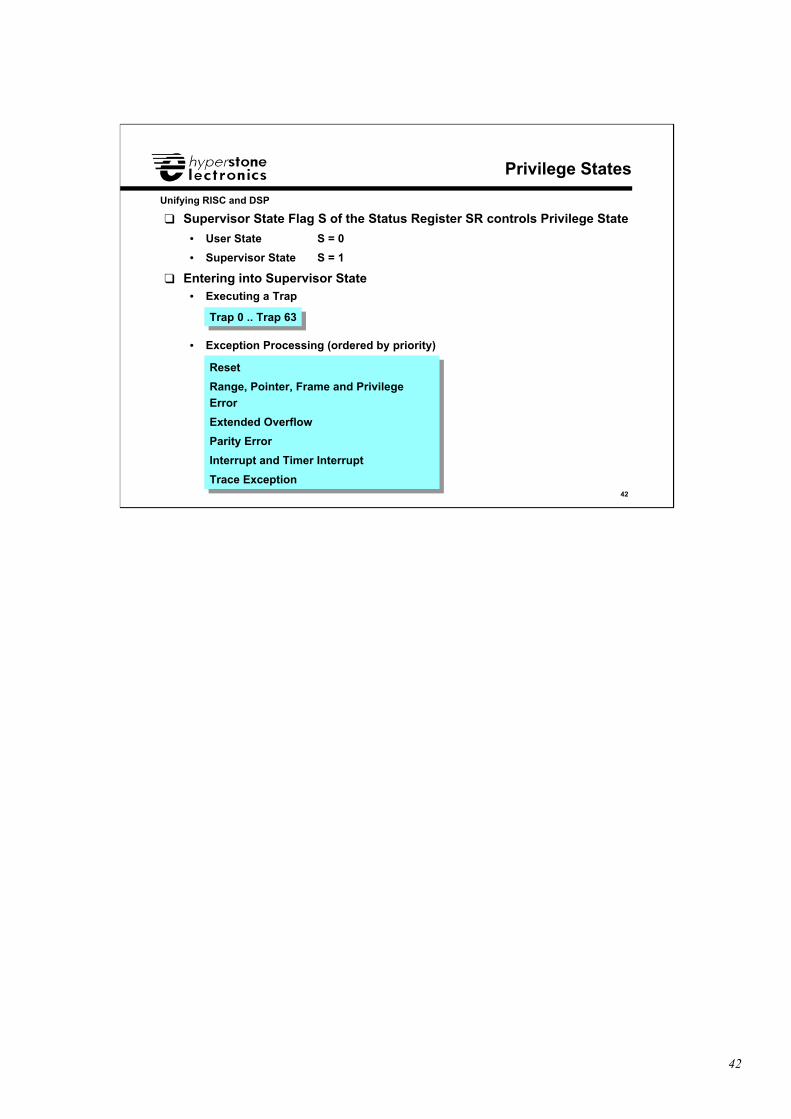
❑ Supervisor State Flag S of the Status Register SR controls Privilege State
• User State S = 0
• Supervisor State S = 1
❑ Entering into Supervisor State• Executing a Trap
• Exception Processing (ordered by priority)
Privilege States
Reset
Range, Pointer, Frame and PrivilegeError
Extended Overflow
Parity Error
Interrupt and Timer Interrupt
Trace Exception
Reset
Range, Pointer, Frame and PrivilegeError
Extended Overflow
Parity Error
Interrupt and Timer Interrupt
Trace Exception
Trap 0 .. Trap 63Trap 0 .. Trap 63
43
43
Unifying RISC and DSP
Trap Entry Table (1)
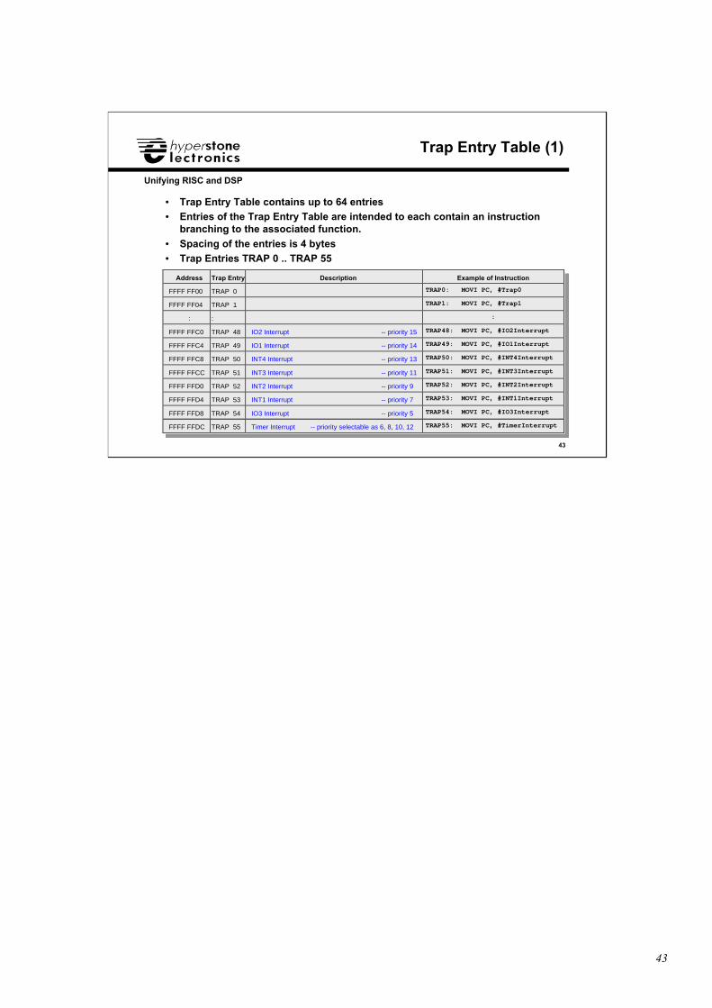
• Trap Entry Table contains up to 64 entries• Entries of the Trap Entry Table are intended to each contain an instruction
branching to the associated function.
• Spacing of the entries is 4 bytes• Trap Entries TRAP 0 .. TRAP 55
Address Trap Entry Description Example of Instruction
FFFF FF00 TRAP 0 TRAP0: MOVI PC, #Trap0
FFFF FF04 TRAP 1 TRAP1: MOVI PC, #Trap1
: : :
FFFF FFC0 TRAP 48 IO2 Interrupt -- priority 15 TRAP48: MOVI PC, #IO2Interrupt
FFFF FFC4 TRAP 49 IO1 Interrupt -- priority 14 TRAP49: MOVI PC, #IO1Interrupt
FFFF FFC8 TRAP 50 INT4 Interrupt -- priority 13 TRAP50: MOVI PC, #INT4Interrupt
FFFF FFCC TRAP 51 INT3 Interrupt -- priority 11 TRAP51: MOVI PC, #INT3Interrupt
FFFF FFD0 TRAP 52 INT2 Interrupt -- priority 9 TRAP52: MOVI PC, #INT2Interrupt
FFFF FFD4 TRAP 53 INT1 Interrupt -- priority 7 TRAP53: MOVI PC, #INT1Interrupt
FFFF FFD8 TRAP 54 IO3 Interrupt -- priority 5 TRAP54: MOVI PC, #IO3Interrupt
FFFF FFDC TRAP 55 Timer Interrupt -- priority selectable as 6, 8, 10, 12 TRAP55: MOVI PC, #TimerInterrupt
44
44
Unifying RISC and DSP
Trap Entry Table (2)
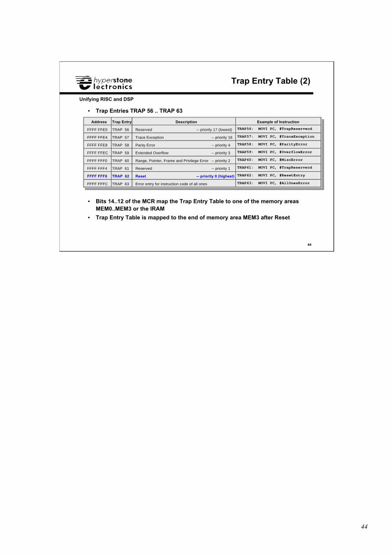
• Trap Entries TRAP 56 .. TRAP 63
Address Trap Entry Description Example of Instruction
FFFF FFE0 TRAP 56 Reserved -- priority 17 (lowest) TRAP56: MOVI PC, #TrapReservecd
FFFF FFE4 TRAP 57 Trace Exception -- priority 16 TRAP57: MOVI PC, #TraceException
FFFF FFE8 TRAP 58 Parity Error -- priority 4 TRAP58: MOVI PC, #ParityError
FFFF FFEC TRAP 59 Extended Overflow -- priority 3 TRAP59: MOVI PC, #OverflowError
FFFF FFF0 TRAP 60 Range, Pointer, Frame and Privilege Error -- priority 2 TRAP60: MOVI PC, #MiscError
FFFF FFF4 TRAP 61 Reserved -- priority 1 TRAP61: MOVI PC, #TrapReservecd
FFFF FFF8 TRAP 62 Reset -- priority 0 (highest) TRAP62: MOVI PC, #ResetEntry
FFFF FFFC TRAP 63 Error entry for instruction code of all ones TRAP63: MOVI PC, #AllOnesError
• Bits 14..12 of the MCR map the Trap Entry Table to one of the memory areasMEM0..MEM3 or the IRAM
• Trap Entry Table is mapped to the end of memory area MEM3 after Reset
45
45
Unifying RISC and DSP
Interrupt-Lock Flag L
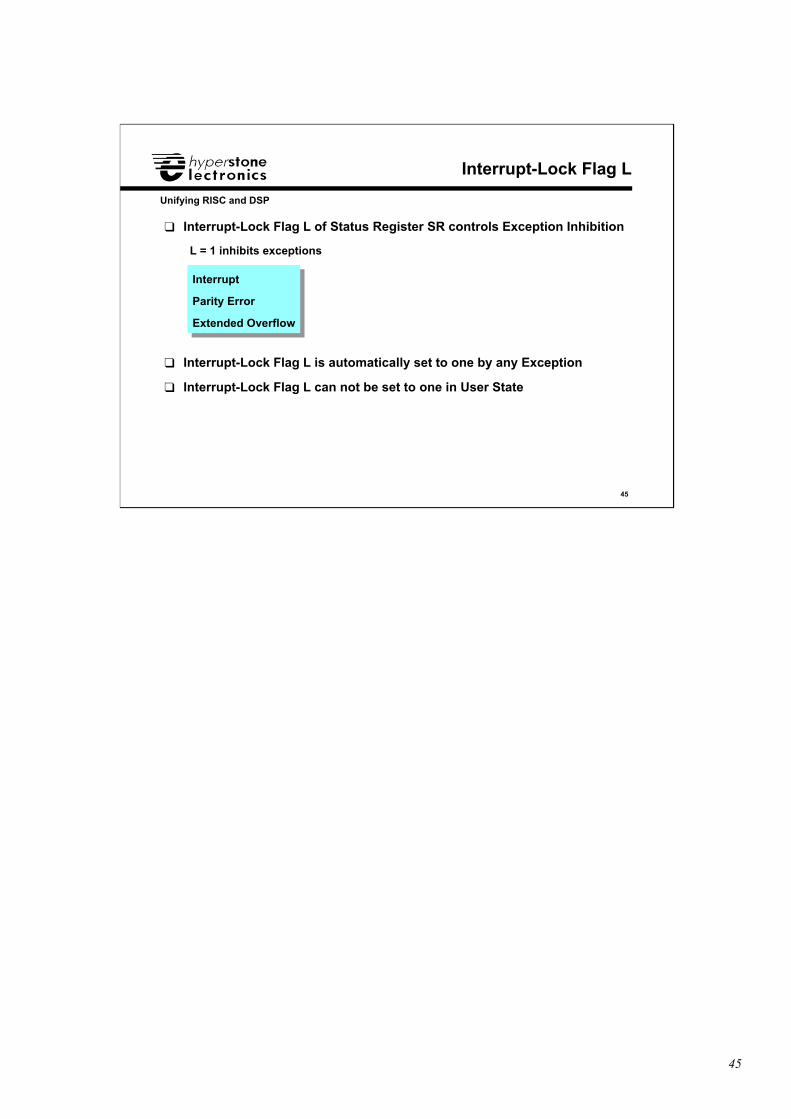
❑ Interrupt-Lock Flag L of Status Register SR controls Exception Inhibition
L = 1 inhibits exceptions
❑ Interrupt-Lock Flag L is automatically set to one by any Exception
❑ Interrupt-Lock Flag L can not be set to one in User State
Interrupt
Parity Error
Extended Overflow
Interrupt
Parity Error
Extended Overflow
46
46
Unifying RISC and DSP
Global Registers
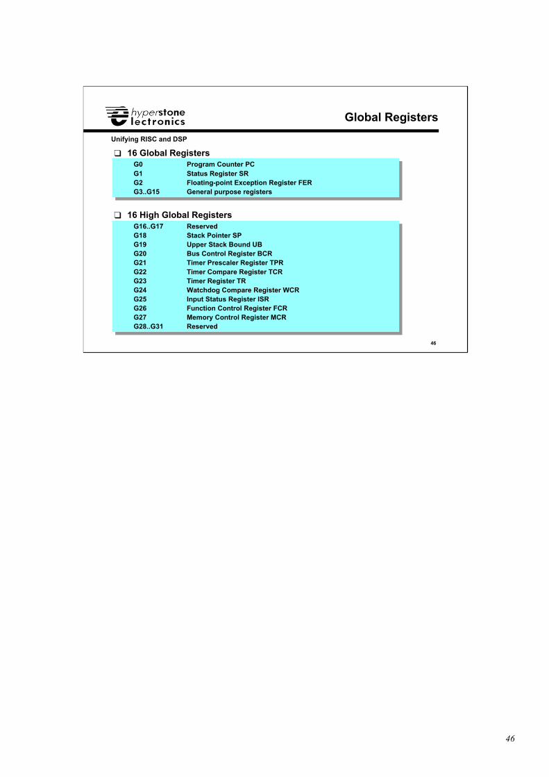
❑ 16 Global Registers
G0 Program Counter PCG1 Status Register SRG2 Floating-point Exception Register FERG3..G15 General purpose registers
G0 Program Counter PCG1 Status Register SRG2 Floating-point Exception Register FERG3..G15 General purpose registers
G16..G17 ReservedG18 Stack Pointer SPG19 Upper Stack Bound UBG20 Bus Control Register BCRG21 Timer Prescaler Register TPRG22 Timer Compare Register TCRG23 Timer Register TRG24 Watchdog Compare Register WCRG25 Input Status Register ISRG26 Function Control Register FCRG27 Memory Control Register MCRG28..G31 Reserved
G16..G17 ReservedG18 Stack Pointer SPG19 Upper Stack Bound UBG20 Bus Control Register BCRG21 Timer Prescaler Register TPRG22 Timer Compare Register TCRG23 Timer Register TRG24 Watchdog Compare Register WCRG25 Input Status Register ISRG26 Function Control Register FCRG27 Memory Control Register MCRG28..G31 Reserved
❑ 16 High Global Registers
47
47
Unifying RISC and DSP
Global Registers and High Global Flag
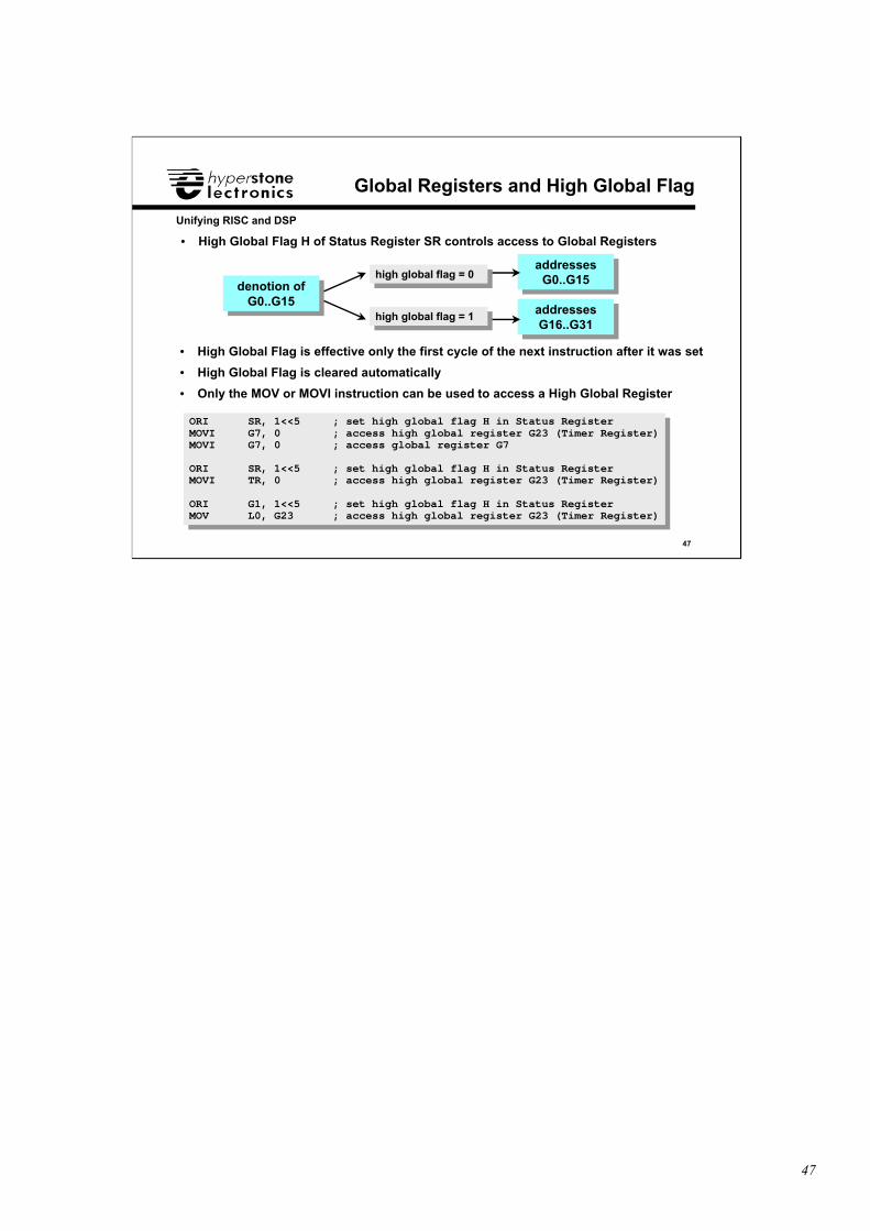
• High Global Flag H of Status Register SR controls access to Global Registers
high global flag = 0high global flag = 0
denotion ofG0..G15
denotion ofG0..G15
high global flag = 1high global flag = 1
addressesG0..G15
addressesG0..G15
addressesG16..G31
addressesG16..G31
• High Global Flag is effective only the first cycle of the next instruction after it was set
• High Global Flag is cleared automatically
• Only the MOV or MOVI instruction can be used to access a High Global Register
ORI SR, 1<<5 ; set high global flag H in Status RegisterMOVI G7, 0 ; access high global register G23 (Timer Register)MOVI G7, 0 ; access global register G7
ORI SR, 1<<5 ; set high global flag H in Status RegisterMOVI TR, 0 ; access high global register G23 (Timer Register)
ORI G1, 1<<5 ; set high global flag H in Status RegisterMOV L0, G23 ; access high global register G23 (Timer Register)
48
48
Unifying RISC and DSP
Supervisor State
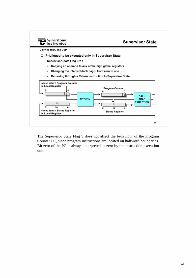
❑ Privileged to be executed only in Supervisor State
Supervisor State Flag S = 1
• Copying an operand to any of the high global registers
• Changing the interrupt-lock flag L from zero to one
• Returning through a Return instruction to Supervisor State
saved return Program Counterin Local Register
31 0
saved return Status Registerin Local Register
31 18 0
S
S
Program Counter31 0
Status Register31 18 0
S
S
RETURNRETURNCALLTRAP
EXCEPTION
CALLTRAP
EXCEPTION
The Supervisor State Flag S does not affect the behaviour of the ProgramCounter PC, since program instructions are located on halfword boundaries.Bit zero of the PC is always interpreted as zero by the instruction executionunit.
49
49
Unifying RISC and DSP
Runtime Stack Initialization (1)
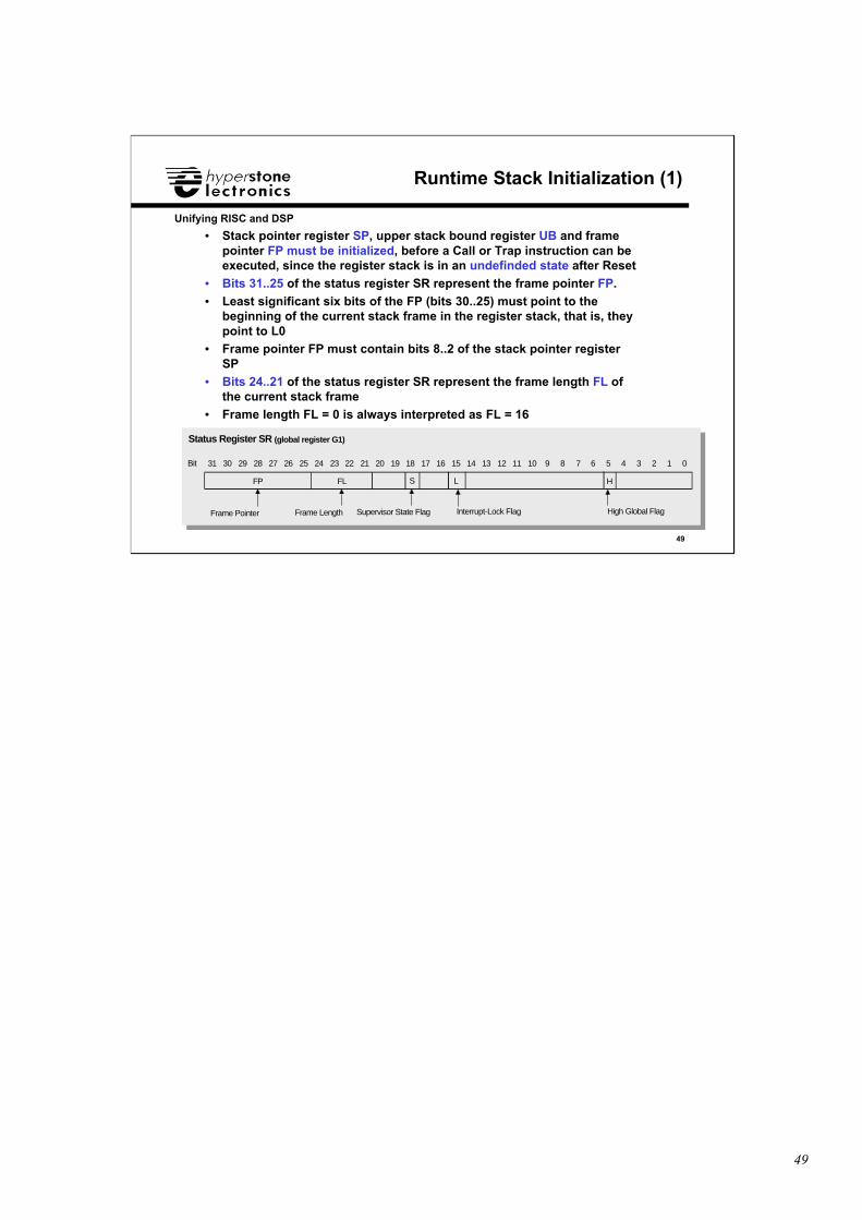
• Stack pointer register SP, upper stack bound register UB and framepointer FP must be initialized, before a Call or Trap instruction can beexecuted, since the register stack is in an undefinded state after Reset
• Bits 31..25 of the status register SR represent the frame pointer FP.
• Least significant six bits of the FP (bits 30..25) must point to thebeginning of the current stack frame in the register stack, that is, theypoint to L0
• Frame pointer FP must contain bits 8..2 of the stack pointer registerSP
• Bits 24..21 of the status register SR represent the frame length FL ofthe current stack frame
• Frame length FL = 0 is always interpreted as FL = 16
Frame Pointer Frame Length
2829
FL
31 30 27 26 25 24 23 22 21 20 19 18 17 16
FP
Status Register SR (global register G1)
Bit
S
Supervisor State Flag
1213
H
15 14 11 10 9 8 7 6 5 4 3 2 1 0
High Global Flag
L
Interrupt-Lock Flag
50
50
Unifying RISC and DSP
Runtime Stack Initialization (2)
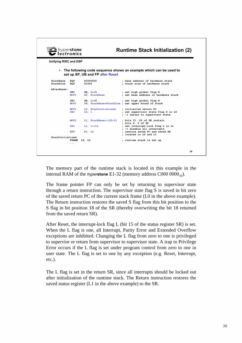
• The following code sequence shows an example which can be used toset up SP, UB and FP after Reset
StackBase EQU $C000000 ; base address of hardware stackStackSize EQU $1000 ; stack size of hardware stack
AfterReset: ORI SR, 1<<5 ; set high global flag H MOVI SP, StackBase ; set base address of hardware stack
ORI SR, 1<<5 ; set high global flag H MOVI UB, StackBase+StackSize ; set upper bound of stack
MOVI L0, StackInitialized ; initialize return PC ORI L0, 1 ; set supervisor state flag S in L0 ; -> return to supervisor state
MOVI L1, StackBase<<(25-2) ; bits 31..25 of SR contain ; bits 8..2 of SP ORI L1, 1<<15 ; set interrupt-lock flag L in L1 ; -> disable all interrupts RET PC, L0 ; restore saved PC and saved SR ; located in L0 and L1StackInitialized: FRAME L0, L0 ; runtime stack is set up ...
The memory part of the runtime stack is located in this example in theinternal RAM of the hyperstone E1-32 (memory address C000 000016).
The frame pointer FP can only be set by returning to supervisor statethrough a return instruction. The supervisor state flag S is saved in bit zeroof the saved return PC of the current stack frame (L0 in the above example).The Return instruction restores the saved S flag from this bit position to theS flag in bit position 18 of the SR (thereby overwriting the bit 18 returnedfrom the saved return SR).
After Reset, the interrupt-lock flag L (bit 15 of the status register SR) is set.When the L flag is one, all Interrupt, Parity Error and Extended Overflowexceptions are inhibited. Changing the L flag from zero to one is privilegedto supervior or return from supervisor to supervisor state. A trap to PrivilegeError occurs if the L flag is set under program control from zero to one inuser state. The L flag is set to one by any exception (e.g. Reset, Interrupt,etc.).
The L flag is set in the return SR, since all interrupts should be locked outafter initialization of the runtime stack. The Return instruction restores thesaved status register (L1 in the above example) to the SR.
51
51
Unifying RISC and DSP
Power-Down Mode
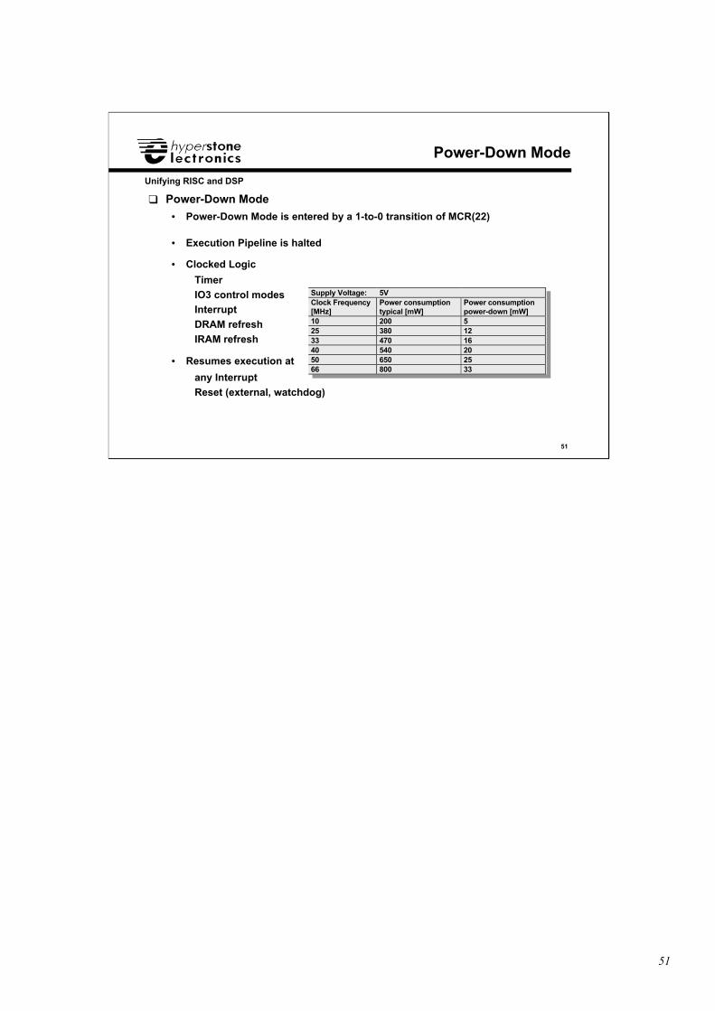
❑ Power-Down Mode
• Power-Down Mode is entered by a 1-to-0 transition of MCR(22)
• Execution Pipeline is halted
• Clocked Logic
Timer
IO3 control modesInterrupt
DRAM refresh
IRAM refresh
• Resumes execution at
any Interrupt
Reset (external, watchdog)
Supply Voltage: 5VClock Frequency[MHz]
Power consumptiontypical [mW]
Power consumptionpower-down [mW]
10 200 525 380 1233 470 1640 540 2050 650 2566 800 33
52
52
Unifying RISC and DSP
Sleep Mode (only E1-32X)
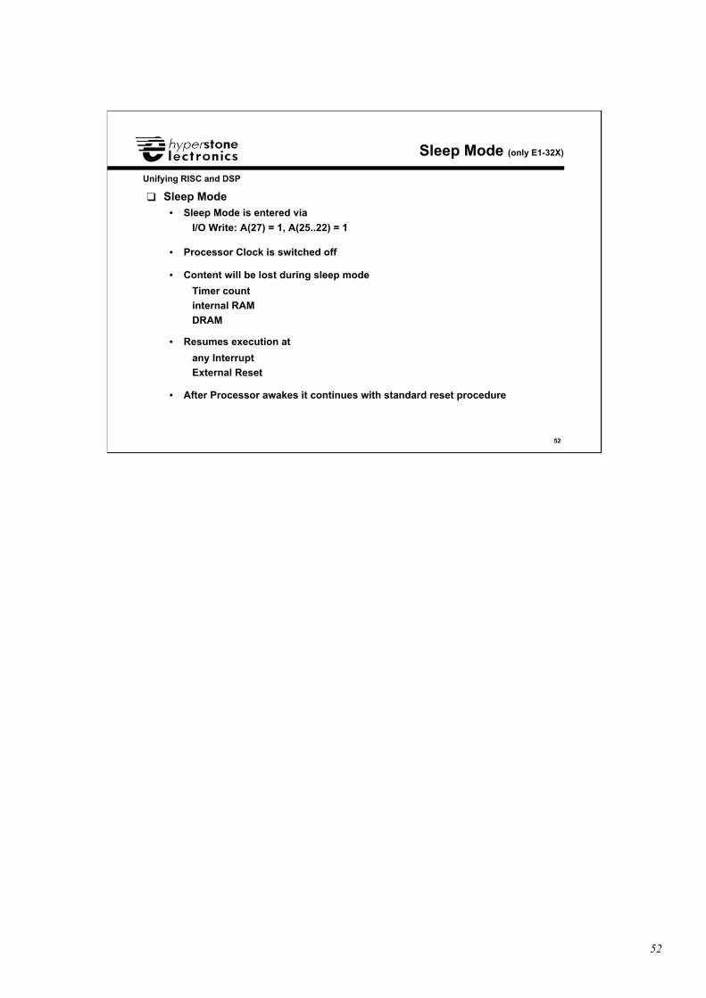
❑ Sleep Mode• Sleep Mode is entered via
I/O Write: A(27) = 1, A(25..22) = 1
• Processor Clock is switched off
• Content will be lost during sleep mode
Timer count
internal RAM
DRAM
• Resumes execution at
any Interrupt
External Reset
• After Processor awakes it continues with standard reset procedure
53
53
Unifying RISC and DSP
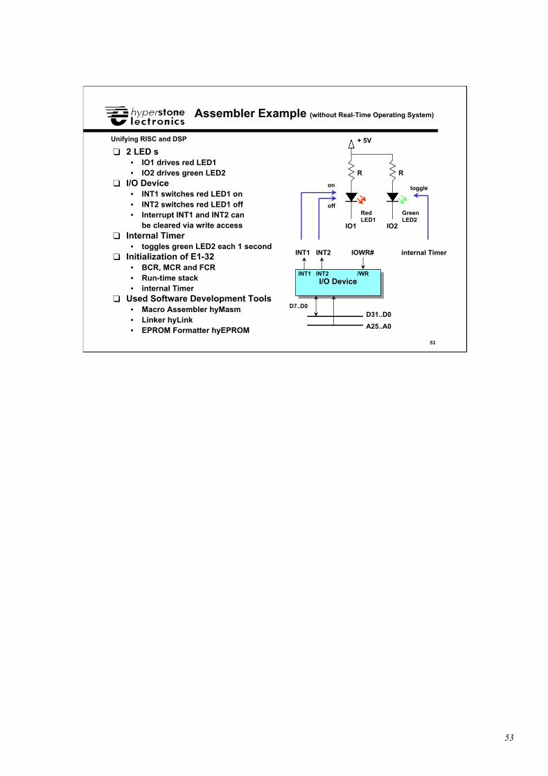
Assembler Example (without Real-Time Operating System)
❑ 2 LED’s• IO1 drives red LED1• IO2 drives green LED2
❑ I/O Device• INT1 switches red LED1 on• INT2 switches red LED1 off• Interrupt INT1 and INT2 can
be cleared via write access❑ Internal Timer
• toggles green LED2 each 1 second❑ Initialization of E1-32
• BCR, MCR and FCR• Run-time stack• internal Timer
❑ Used Software Development Tools• Macro Assembler hyMasm• Linker hyLink• EPROM Formatter hyEPROM
I/O DeviceI/O Device
IOWR#
/WR
INT1
INT1
D31..D0D7..D0
A25..A0
INT2
INT2
IO1 IO2
R R
+ 5V
internal Timer
on
off
toggle
RedLED1
GreenLED2
54
54
Unifying RISC and DSP
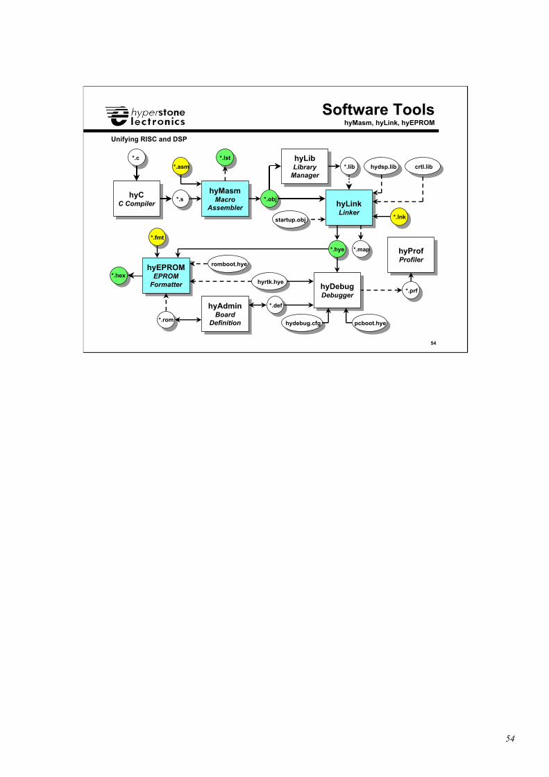
hyCC Compiler
hyCC Compiler
hyMasmMacro
Assembler
hyMasmMacro
Assembler hyLinkLinker
hyLinkLinker
hyProfProfiler
hyProfProfiler
hyEPROMEPROM
Formatter
hyEPROMEPROM
Formatter
hyAdminBoard
Definition
hyAdminBoard
Definition
hyLibLibrary
Manager
hyLibLibrary
Manager
hyDebugDebugger
hyDebugDebugger
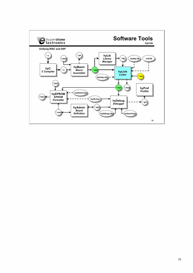
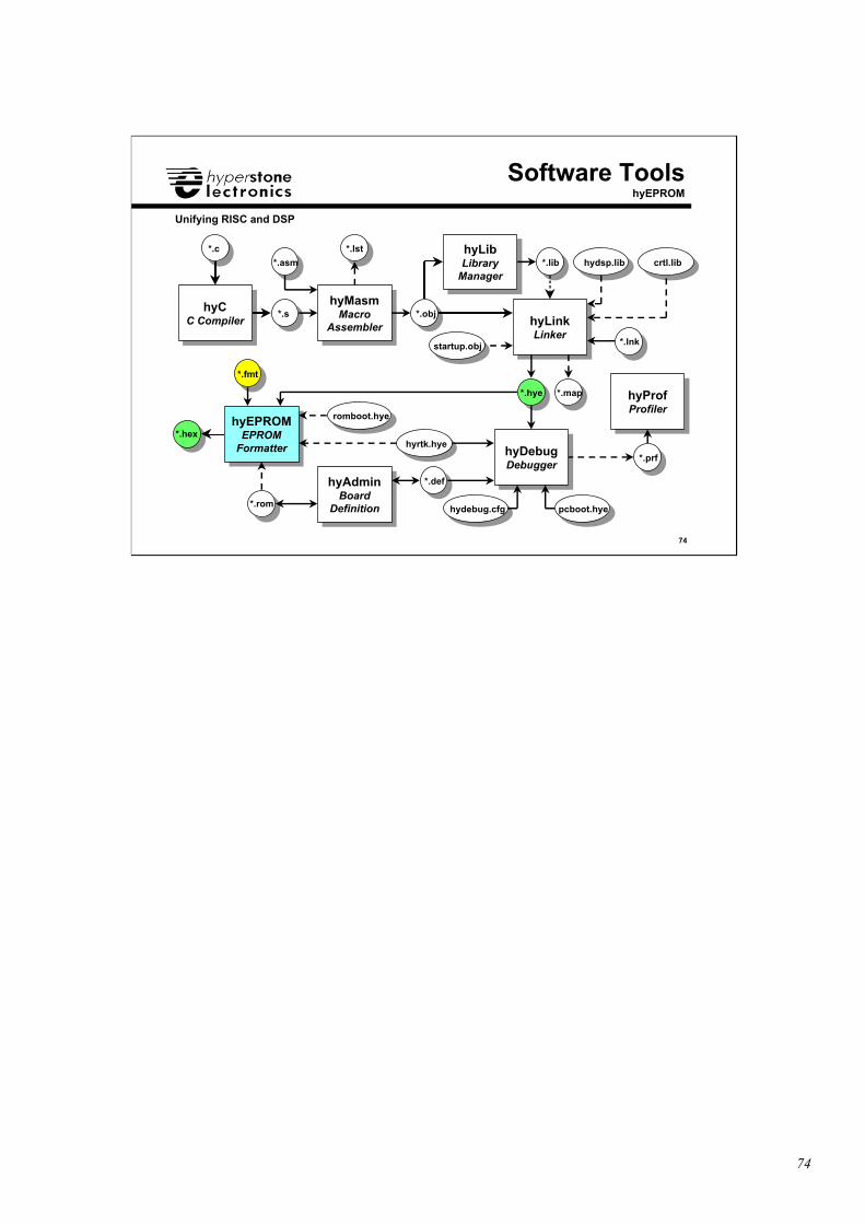
Software ToolshyMasm, hyLink, hyEPROM
romboot.hye
pcboot.hyehydebug.cfg
hyrtk.hye
*.c
*.s
*.asm
*.obj
*.lib
*.hye
*.prf
*.fmt
*.hex
*.rom
*.def
*.lnk
*.lst
*.map
hydsp.lib crtl.lib
startup.obj
55
55
Unifying RISC and DSP
Assembler Segment: EntryTable
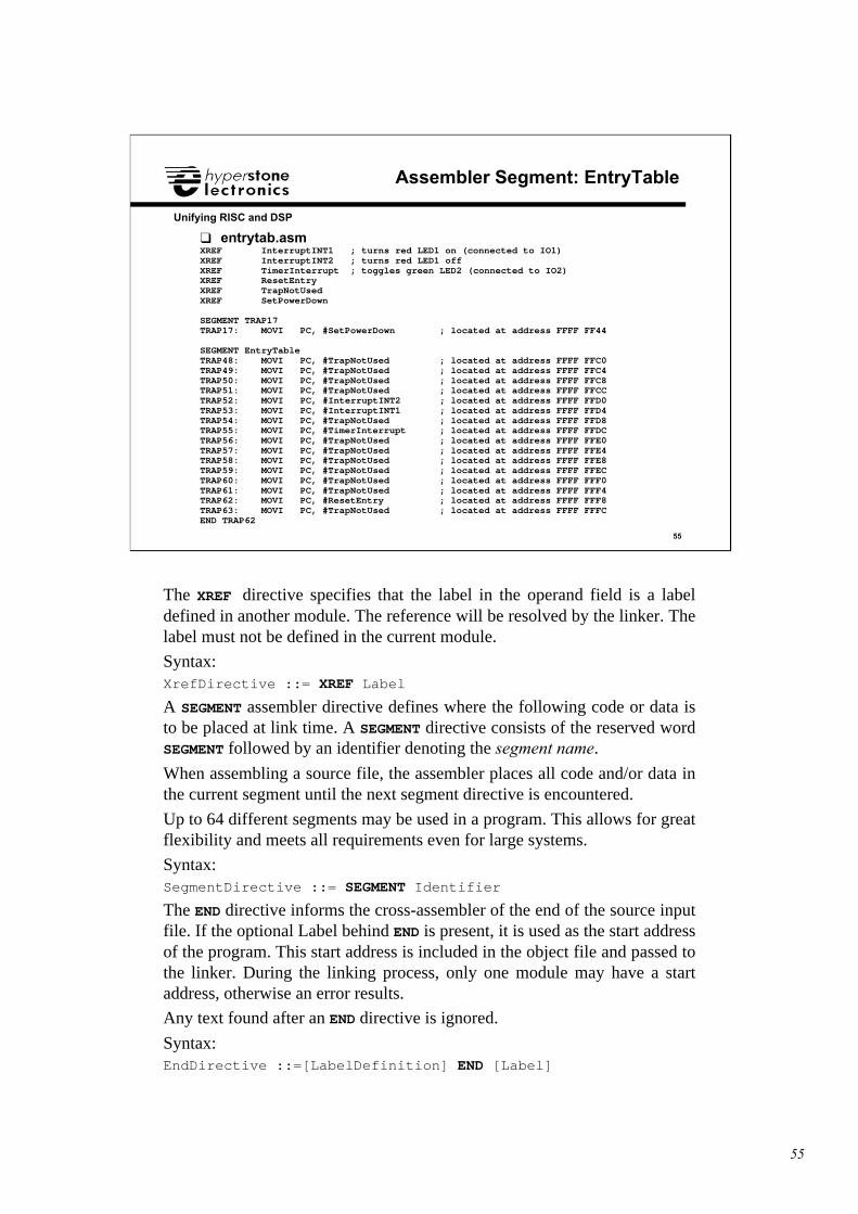
❑ entrytab.asmXREF InterruptINT1 ; turns red LED1 on (connected to IO1)XREF InterruptINT2 ; turns red LED1 offXREF TimerInterrupt ; toggles green LED2 (connected to IO2)XREF ResetEntryXREF TrapNotUsedXREF SetPowerDown
SEGMENT TRAP17TRAP17: MOVI PC, #SetPowerDown ; located at address FFFF FF44
SEGMENT EntryTableTRAP48: MOVI PC, #TrapNotUsed ; located at address FFFF FFC0TRAP49: MOVI PC, #TrapNotUsed ; located at address FFFF FFC4TRAP50: MOVI PC, #TrapNotUsed ; located at address FFFF FFC8TRAP51: MOVI PC, #TrapNotUsed ; located at address FFFF FFCCTRAP52: MOVI PC, #InterruptINT2 ; located at address FFFF FFD0TRAP53: MOVI PC, #InterruptINT1 ; located at address FFFF FFD4TRAP54: MOVI PC, #TrapNotUsed ; located at address FFFF FFD8TRAP55: MOVI PC, #TimerInterrupt ; located at address FFFF FFDCTRAP56: MOVI PC, #TrapNotUsed ; located at address FFFF FFE0TRAP57: MOVI PC, #TrapNotUsed ; located at address FFFF FFE4TRAP58: MOVI PC, #TrapNotUsed ; located at address FFFF FFE8TRAP59: MOVI PC, #TrapNotUsed ; located at address FFFF FFECTRAP60: MOVI PC, #TrapNotUsed ; located at address FFFF FFF0TRAP61: MOVI PC, #TrapNotUsed ; located at address FFFF FFF4TRAP62: MOVI PC, #ResetEntry ; located at address FFFF FFF8TRAP63: MOVI PC, #TrapNotUsed ; located at address FFFF FFFCEND TRAP62
The XREF directive specifies that the label in the operand field is a labeldefined in another module. The reference will be resolved by the linker. Thelabel must not be defined in the current module.
Syntax:XrefDirective ::= XREF Label
A SEGMENT assembler directive defines where the following code or data isto be placed at link time. A SEGMENT directive consists of the reserved wordSEGMENT followed by an identifier denoting the segment name.
When assembling a source file, the assembler places all code and/or data inthe current segment until the next segment directive is encountered.
Up to 64 different segments may be used in a program. This allows for greatflexibility and meets all requirements even for large systems.
Syntax:SegmentDirective ::= SEGMENT Identifier
The END directive informs the cross-assembler of the end of the source inputfile. If the optional Label behind END is present, it is used as the start addressof the program. This start address is included in the object file and passed tothe linker. During the linking process, only one module may have a startaddress, otherwise an error results.
Any text found after an END directive is ignored.
Syntax:EndDirective ::=[LabelDefinition] END [Label]
56
56
Unifying RISC and DSP
Assembler Segment: ResetSegment (1)
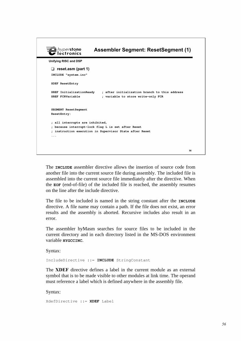
❑ reset.asm (part 1)INCLUDE "system.inc"
XDEF ResetEntry
XREF InitializationReady ; after initialization branch to this address
XREF FCRVariable ; variable to store write-only FCR
SEGMENT ResetSegment
ResetEntry:
; all interrupts are inhibited,
; because interrupt-lock flag L is set after Reset
; instruction execution in Supervisor State after Reset
...
The INCLUDE assembler directive allows the insertion of source code fromanother file into the current source file during assembly. The included file isassembled into the current source file immediately after the directive. Whenthe EOF (end-of-file) of the included file is reached, the assembly resumeson the line after the include directive.
The file to be included is named in the string constant after the INCLUDEdirective. A file name may contain a path. If the file does not exist, an errorresults and the assembly is aborted. Recursive includes also result in anerror.
The assembler hyMasm searches for source files to be included in thecurrent directory and in each directory listed in the MS-DOS environmentvariable HYGCCINC.
Syntax:
IncludeDirective ::= INCLUDE StringConstant
The XDEF directive defines a label in the current module as an externalsymbol that is to be made visible to other modules at link time. The operandmust reference a label which is defined anywhere in the assembly file.
Syntax:
XdefDirective ::= XDEF Label
57
57
Unifying RISC and DSP
Assembler Segment: VariablesSegment
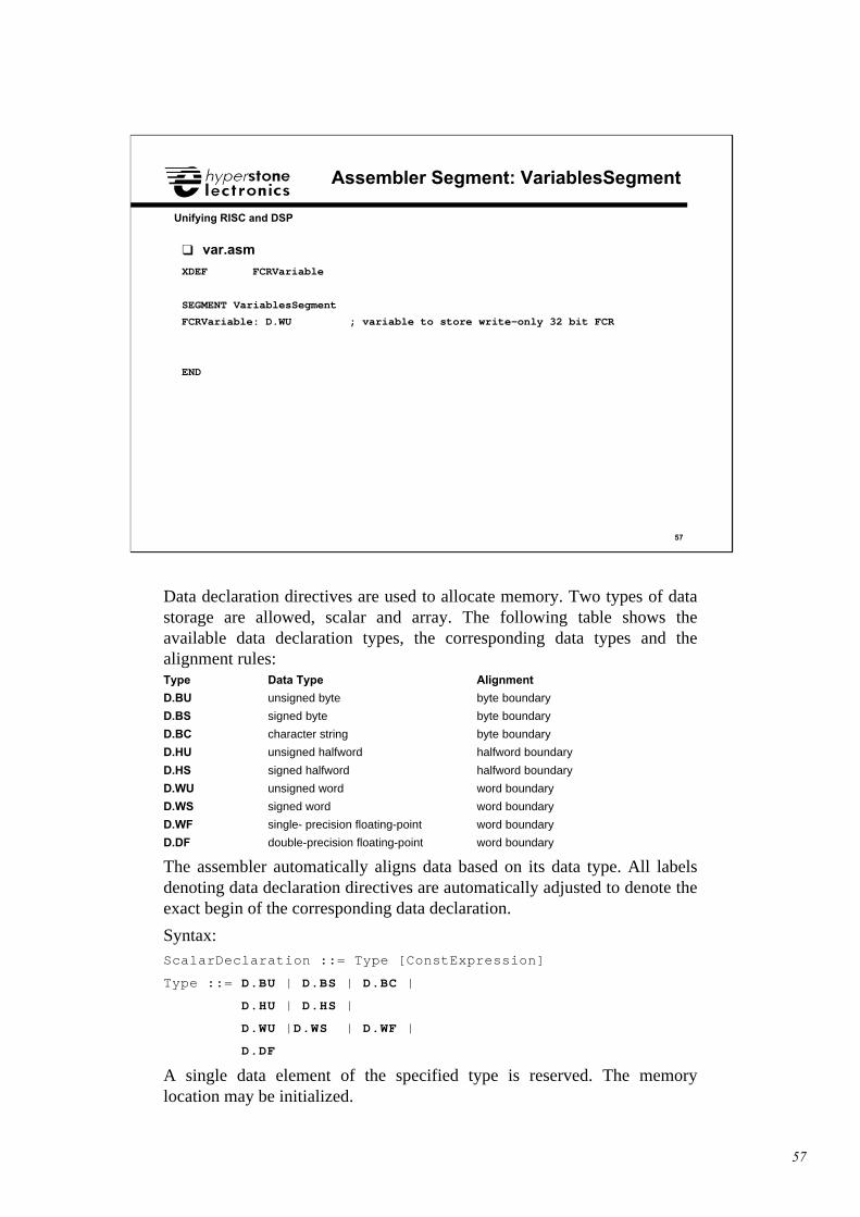
❑ var.asm
XDEF FCRVariable
SEGMENT VariablesSegment
FCRVariable: D.WU ; variable to store write-only 32 bit FCR
END
Data declaration directives are used to allocate memory. Two types of datastorage are allowed, scalar and array. The following table shows theavailable data declaration types, the corresponding data types and thealignment rules:Type Data Type Alignment
D.BU unsigned byte byte boundary
D.BS signed byte byte boundary
D.BC character string byte boundary
D.HU unsigned halfword halfword boundary
D.HS signed halfword halfword boundary
D.WU unsigned word word boundary
D.WS signed word word boundary
D.WF single- precision floating-point word boundary
D.DF double-precision floating-point word boundary
The assembler automatically aligns data based on its data type. All labelsdenoting data declaration directives are automatically adjusted to denote theexact begin of the corresponding data declaration.
Syntax:ScalarDeclaration ::= Type [ConstExpression]
Type ::= D.BU | D.BS | D.BC |
D.HU | D.HS |
D.WU |D.WS | D.WF |
D.DF
A single data element of the specified type is reserved. The memorylocation may be initialized.
58
58
Unifying RISC and DSP
System Include File
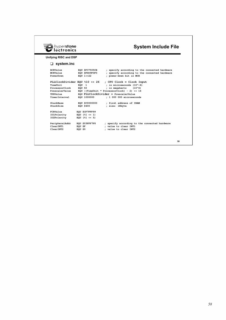
❑ system.inc
BCRValue EQU $F37505CB ; specify according to the connected hardwareMCRValue EQU $FDD9F0F0 ; specify according to the connected hardwarePowerDown EQU 1<<22 ; power-down bit in MCR
PLLClockDivider EQU %10 << 26 ; CPU Clock = Clock InputTimeUnit EQU 1 ; in microseconds (10^-6)ProcessorClock EQU 50 ; in megahertz (10^6)PrescalerValue EQU ((TimeUnit * ProcessorClock) - 2) << 16TPRValue EQU PLLClockDivider + PrescalerValueTimerInterval EQU 1000000 ; 1 000 000 microseconds
StackBase EQU $C0000000 ; first address of IRAMStackSize EQU $400 ; size: 1Kbyte
FCRValue EQU $CF7FFF99IO1Polarity EQU (%1 << 1)IO2Polarity EQU (%1 << 5)
PeripheralAddr EQU $03FFF7F8 ; specify according to the connected hardwareClearINT1 EQU $F ; value to clear INT1ClearINT2 EQU $0 ; value to clear INT2
59
59
Unifying RISC and DSP
Assembler Segment: ResetSegment (2)
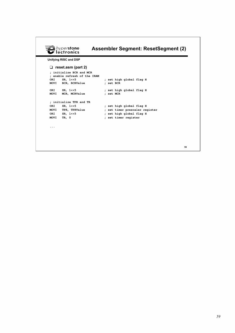
❑ reset.asm (part 2); initialize BCR and MCR; enable refresh of the IRAMORI SR, 1<<5 ; set high global flag HMOVI BCR, BCRValue ; set BCR
ORI SR, 1<<5 ; set high global flag HMOVI MCR, MCRValue ; set MCR
; initialize TPR and TRORI SR, 1<<5 ; set high global flag HMOVI TPR, TPRValue ; set timer prescaler registerORI SR, 1<<5 ; set high global flag HMOVI TR, 0 ; set timer register
...
60
60
Unifying RISC and DSP
Assembler Segment: ResetSegment (3)
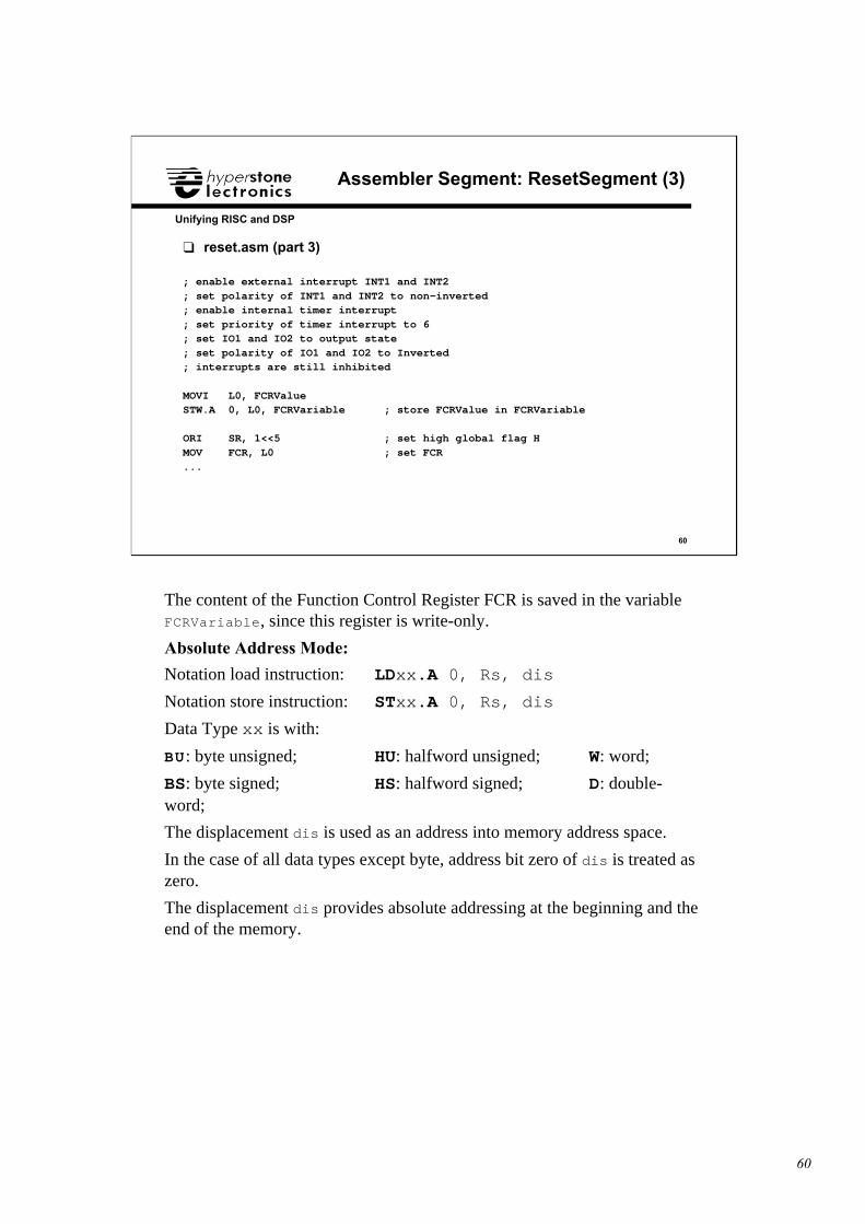
❑ reset.asm (part 3)
; enable external interrupt INT1 and INT2; set polarity of INT1 and INT2 to non-inverted; enable internal timer interrupt; set priority of timer interrupt to 6; set IO1 and IO2 to output state; set polarity of IO1 and IO2 to Inverted; interrupts are still inhibited
MOVI L0, FCRValueSTW.A 0, L0, FCRVariable ; store FCRValue in FCRVariable
ORI SR, 1<<5 ; set high global flag HMOV FCR, L0 ; set FCR...
The content of the Function Control Register FCR is saved in the variableFCRVariable, since this register is write-only.
Absolute Address Mode:
Notation load instruction: LDxx.A 0, Rs, dis
Notation store instruction: STxx.A 0, Rs, dis
Data Type xx is with:
BU: byte unsigned; HU: halfword unsigned; W: word;
BS: byte signed; HS: halfword signed; D: double-word;
The displacement dis is used as an address into memory address space.
In the case of all data types except byte, address bit zero of dis is treated aszero.
The displacement dis provides absolute addressing at the beginning and theend of the memory.
61
61
Unifying RISC and DSP
Assembler Segment: ResetSegment (4)
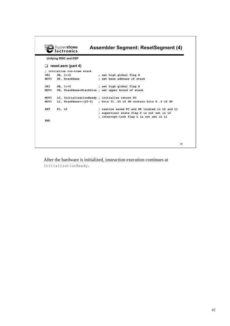
❑ reset.asm (part 4); initialize run-time stackORI SR, 1<<5 ; set high global flag HMOVI SP, StackBase ; set base address of stack
ORI SR, 1<<5 ; set high global flag HMOVI UB, StackBase+StackSize ; set upper bound of stack
MOVI L0, InitializationReady ; initialize return PCMOVI L1, StackBase<<(25-2) ; bits 31..25 of SR contain bits 8..2 of SP
RET PC, L0 ; restore saved PC and SR located in L0 and L1 ; supervisor state flag S is not set in L0 ; interrupt-lock flag L is not set in L1END
After the hardware is initialized, instruction execution continues atInitializationReady.
62
62
Unifying RISC and DSP
Assembler Segment: MainSegment
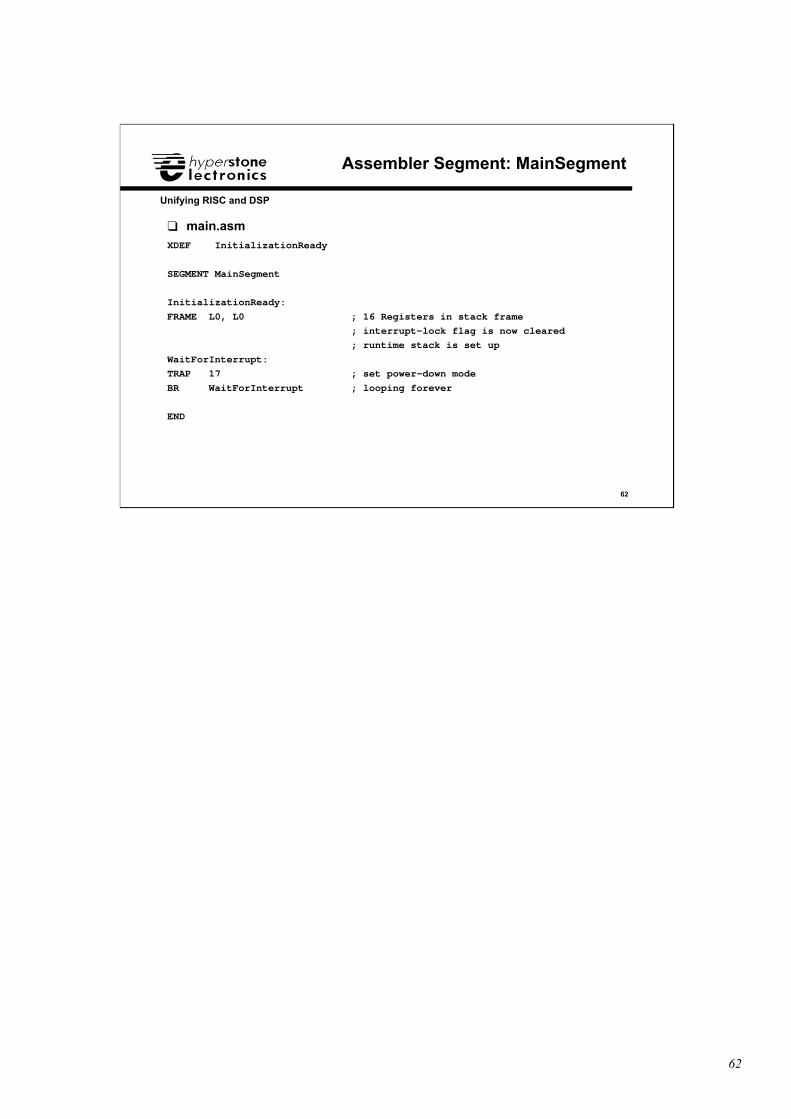
❑ main.asmXDEF InitializationReady
SEGMENT MainSegment
InitializationReady:
FRAME L0, L0 ; 16 Registers in stack frame
; interrupt-lock flag is now cleared
; runtime stack is set up
WaitForInterrupt:
TRAP 17 ; set power-down mode
BR WaitForInterrupt ; looping forever
END
63
63
Unifying RISC and DSP
Assembler Segment: InterruptSegment (1)
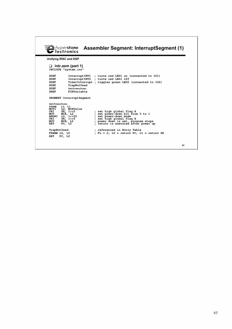
❑ intr.asm (part 1)INCLUDE "system.inc"
XDEF InterruptINT1 ; turns red LED1 on (connected to IO1)XDEF InterruptINT2 ; turns red LED1 offXDEF TimerInterrupt ; toggles green LED2 (connected to IO2)XDEF TrapNotUsedXDEF SetPowerDownXREF FCRVariable
SEGMENT InterruptSegment
SetPowerDown:FRAME L3, L0MOVI L2, MCRValueORI SR, 1<<5 ; set high global flag HMOV MCR, L2 ; set power-down bit from 0 to 1ANDNI L2, 1<<22 ; set power-down modeORI SR, 1<<5 ; set high global flag HMOV MCR, L2 ; power down is set, program stopsRET PC, L0 ; return is executed after power up
TrapNotUsed: ; referenced in Entry TableFRAME L2, L0 ; FL = 2; L0 = return PC, L1 = return SRRET PC, L0
64
64
Unifying RISC and DSP
Assembler Segment: InterruptSegment (2)
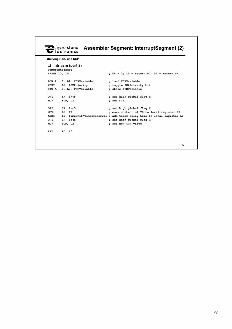
❑ intr.asm (part 2)TimerInterrupt:FRAME L3, L0 ; FL = 3; L0 = return PC, L1 = return SR
LDW.A 0, L2, FCRVariable ; load FCRVariableXORI L2, IO2Polarity ; toggle IO2Polarity bitSTW.A 0, L2, FCRVariable ; store FCRVariable
ORI SR, 1<<5 ; set high global flag HMOV FCR, L2 ; set FCR
ORI SR, 1<<5 ; set high global flag HMOV L2, TR ; move content of TR to local register L0ADDI L2, TimeUnit*TimerInterval ; add timer delay time to local register L0ORI SR, 1<<5 ; set high global flag HMOV TCR, L2 ; set new TCR value
RET PC, L0

65
65
Unifying RISC and DSP
Assembler Segment: InterruptSegment (3)
❑ intr.asm (part 3)InterruptINT1: ; turns red LED1 on (connected to IO1)
FRAME L3, L0 ; FL = 3; L0 = return PC, L1 = return SR
MOVI L2, ClearINT1 ; value to clear INT1
STW.IOA 0, L2, PeripheralAddr ; clear INT1 with I/O write access
LDW.A 0, L2, FCRVariable ; load FCRVariable
ORI L2, IO1Polarity ; set IO1Polarity bit
STW.A 0, L2, FCRVariable ; store FCRVariable
ORI SR, 1<<5 ; set high global flag H
MOV FCR, L2 ; set FCR
RET PC, L0
66
66
Unifying RISC and DSP
Assembler Segment: InterruptSegment (4)
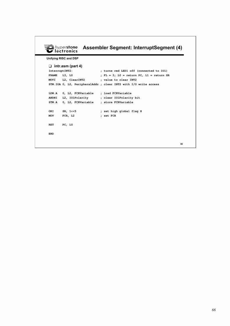
❑ intr.asm (part 4)InterruptINT2: ; turns red LED1 off (connected to IO1)
FRAME L3, L0 ; FL = 3; L0 = return PC, L1 = return SR
MOVI L2, ClearINT2 ; value to clear INT2
STW.IOA 0, L2, PeripheralAddr ; clear INT2 with I/O write access
LDW.A 0, L2, FCRVariable ; load FCRVariable
ANDNI L2, IO1Polarity ; clear IO1Polarity bit
STW.A 0, L2, FCRVariable ; store FCRVariable
ORI SR, 1<<5 ; set high global flag H
MOV FCR, L2 ; set FCR
RET PC, L0
END
67
67
Unifying RISC and DSP
hyCC Compiler
hyCC Compiler
hyMasmMacro
Assembler
hyMasmMacro
Assembler hyLinkLinker
hyLinkLinker
hyProfProfiler
hyProfProfiler
hyEPROMEPROM
Formatter
hyEPROMEPROM
Formatter
hyAdminBoard
Definition
hyAdminBoard
Definition
hyLibLibrary
Manager
hyLibLibrary
Manager
hyDebugDebugger
hyDebugDebugger
Software ToolshyMasm
romboot.hye
pcboot.hyehydebug.cfg
hyrtk.hye
*.c
*.s
*.asm
*.obj
*.lib
*.hye
*.prf
*.fmt
*.hex
*.rom
*.def
*.lnk
*.lst
*.map
hydsp.lib crtl.lib
startup.obj
68
68
Unifying RISC and DSP
Assembler hyMasm (1)
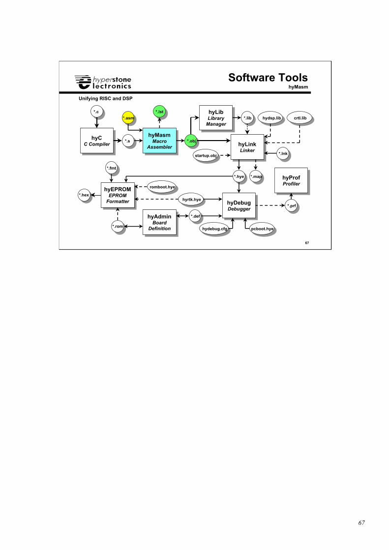
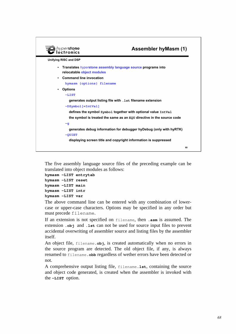
• Translates hyperstone assembly language source programs into
relocatable object modules
• Command line invocation
hymasm {options} filename
• Options
-LIST
generates output listing file with .lst filename extension
-DSymbol[=IntVal]
defines the symbol Symbol together with optional value IntVal
the symbol is treated the same as an EQU directive in the source code
-g
generates debug information for debugger hyDebug (only with hyRTK)
-QUIET
displaying screen title and copyright information is suppressed
The five assembly language source files of the preceding example can betranslated into object modules as follows:hymasm -LIST entrytabhymasm -LIST resethymasm -LIST mainhymasm -LIST intrhymasm -LIST var
The above command line can be entered with any combination of lower-case or upper-case characters. Options may be specified in any order butmust precede filename.If an extension is not specified on filename, then .asm is assumed. Theextension .obj and .lst can not be used for source input files to preventaccidental overwriting of assembler source and listing files by the assembleritself.An object file, filename.obj, is created automatically when no errors inthe source program are detected. The old object file, if any, is alwaysrenamed to filename.obb regardless of wether errors have been detected ornot.A comprehensive output listing file, filename.lst, containing the sourceand object code generated, is created when the assembler is invoked withthe -LIST option.
69
69
Unifying RISC and DSP
Assembler hyMasm (2)
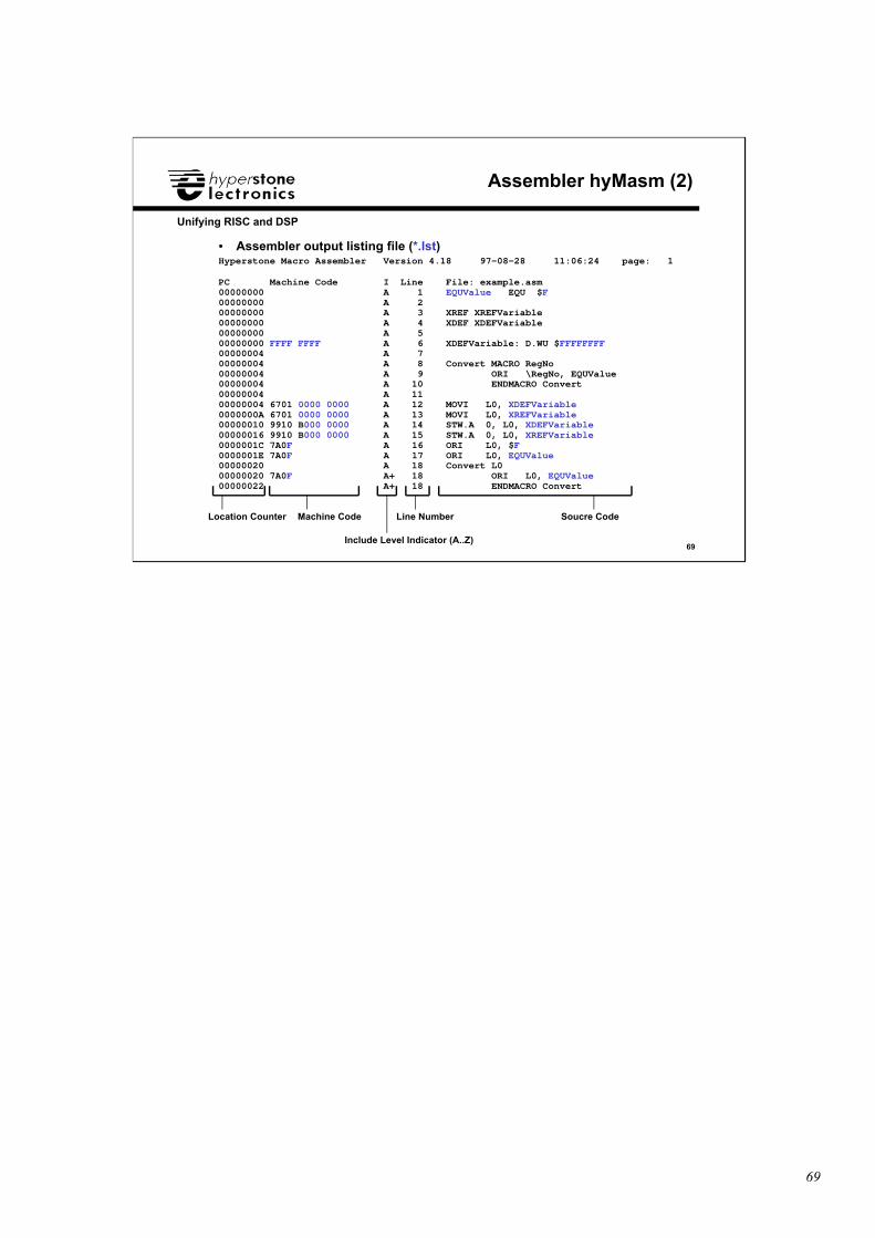
• Assembler output listing file (*.lst)Hyperstone Macro Assembler Version 4.18 97-08-28 11:06:24 page: 1
PC Machine Code I Line File: example.asm00000000 A 1 EQUValue EQU $F00000000 A 200000000 A 3 XREF XREFVariable00000000 A 4 XDEF XDEFVariable00000000 A 500000000 FFFF FFFF A 6 XDEFVariable: D.WU $FFFFFFFF00000004 A 700000004 A 8 Convert MACRO RegNo00000004 A 9 ORI \RegNo, EQUValue00000004 A 10 ENDMACRO Convert00000004 A 1100000004 6701 0000 0000 A 12 MOVI L0, XDEFVariable0000000A 6701 0000 0000 A 13 MOVI L0, XREFVariable00000010 9910 B000 0000 A 14 STW.A 0, L0, XDEFVariable00000016 9910 B000 0000 A 15 STW.A 0, L0, XREFVariable0000001C 7A0F A 16 ORI L0, $F0000001E 7A0F A 17 ORI L0, EQUValue00000020 A 18 Convert L000000020 7A0F A+ 18 ORI L0, EQUValue00000022 A+ 18 ENDMACRO Convert
Location Counter Machine Code
Include Level Indicator (A..Z)
Line Number Soucre Code
70
70
Unifying RISC and DSP
hyCC Compiler
hyCC Compiler
hyMasmMacro
Assembler
hyMasmMacro
Assembler hyLinkLinker
hyLinkLinker
hyProfProfiler
hyProfProfiler
hyEPROMEPROM
Formatter
hyEPROMEPROM
Formatter
hyAdminBoard
Definition
hyAdminBoard
Definition
hyLibLibrary
Manager
hyLibLibrary
Manager
hyDebugDebugger
hyDebugDebugger
Software ToolshyLink
romboot.hye
pcboot.hyehydebug.cfg
hyrtk.hye
*.c
*.s
*.asm
*.obj
*.lib
*.hye
*.prf
*.fmt
*.hex
*.rom
*.def
*.lnk
*.lst
*.map
hydsp.lib crtl.lib
startup.obj
71
71
Unifying RISC and DSP
Linker hyLink
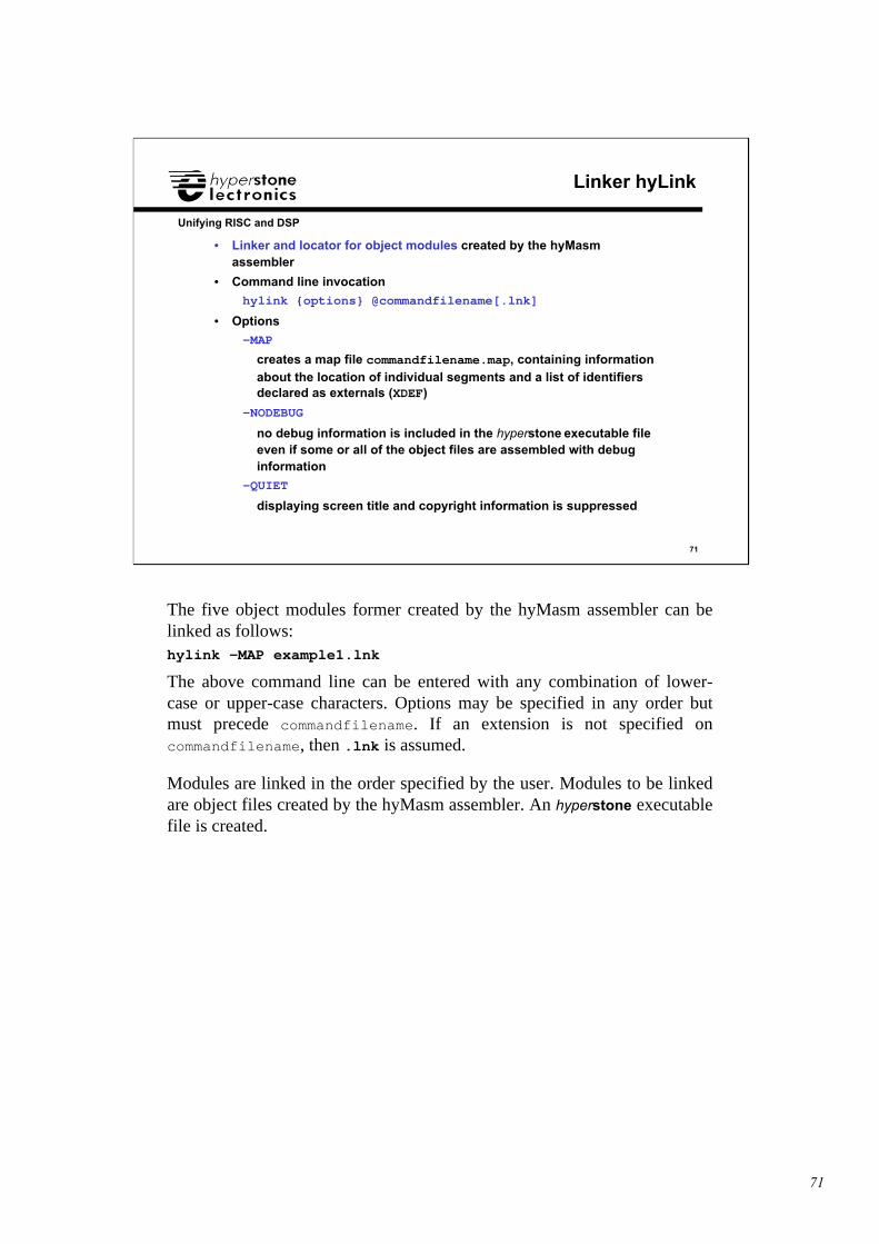
• Linker and locator for object modules created by the hyMasmassembler
• Command line invocation
hylink {options} @commandfilename[.lnk]
• Options
-MAP
creates a map file commandfilename.map, containing informationabout the location of individual segments and a list of identifiersdeclared as externals (XDEF)
-NODEBUG
no debug information is included in the hyperstone executable fileeven if some or all of the object files are assembled with debuginformation
-QUIET
displaying screen title and copyright information is suppressed
The five object modules former created by the hyMasm assembler can belinked as follows:hylink -MAP example1.lnk
The above command line can be entered with any combination of lower-case or upper-case characters. Options may be specified in any order butmust precede commandfilename. If an extension is not specified oncommandfilename, then .lnk is assumed.
Modules are linked in the order specified by the user. Modules to be linkedare object files created by the hyMasm assembler. An hyperstone executablefile is created.
72
72
Unifying RISC and DSP
Linker Command File (1)
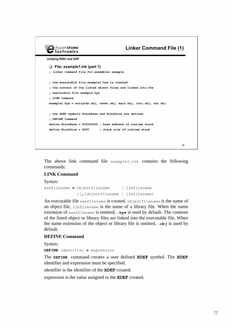
❑ File: example1.lnk (part 1); linker command file for assembler example
; the executable file example1.hye is created
; the content of the listed object files are linked into the
; executable file example.hye
; LINK Command
example1.hye = entrytab.obj, reset.obj, main.obj, intr.obj, var.obj
; the XDEF symbols StackBase and StackSize are defined
; DEFINE Command
define StackBase = $C0000000 ; base address of runtime stack
define StackSize = $400 ; stack size of runtime stack
The above link command file example1.lnk contains the followingcommands:
LINK Command
Syntax:exefilename = objectfilename | libfilename
{[,]objectfilename | libfilename}
An executable file exefilename is created. objectfilename is the name ofan object file, libfilename is the name of a library file. When the nameextension of exefilename is omitted, .hye is used by default. The contentsof the listed object or library files are linked into the executable file. Whenthe name extension of the object or library file is omitted, .obj is used bydefault.
DEFINE Command
Syntax:DEFINE identifier = expression
The DEFINE command creates a user defined XDEF symbol. The XDEFidentifier and expression must be specified.
identifier is the identifier of the XDEF created.
expression is the value assigned to the XDEF created.
73
73
Unifying RISC and DSP
Linker Command File (2)
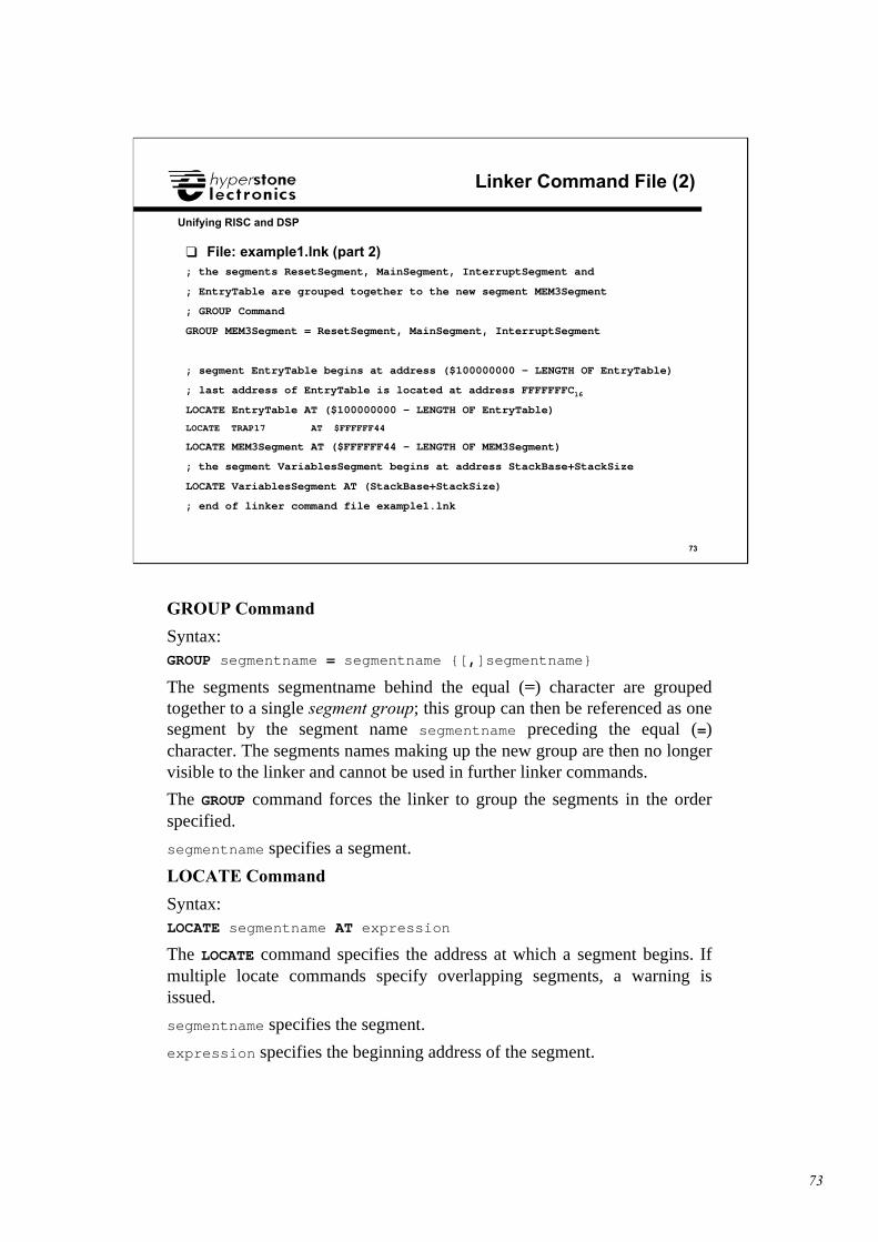
❑ File: example1.lnk (part 2); the segments ResetSegment, MainSegment, InterruptSegment and
; EntryTable are grouped together to the new segment MEM3Segment
; GROUP Command
GROUP MEM3Segment = ResetSegment, MainSegment, InterruptSegment
; segment EntryTable begins at address ($100000000 - LENGTH OF EntryTable)
; last address of EntryTable is located at address FFFFFFFC16
LOCATE EntryTable AT ($100000000 - LENGTH OF EntryTable)
LOCATE TRAP17 AT $FFFFFF44
LOCATE MEM3Segment AT ($FFFFFF44 - LENGTH OF MEM3Segment)
; the segment VariablesSegment begins at address StackBase+StackSize
LOCATE VariablesSegment AT (StackBase+StackSize)
; end of linker command file example1.lnk
GROUP Command
Syntax:GROUP segmentname = segmentname {[,]segmentname}
The segments segmentname behind the equal (=) character are groupedtogether to a single segment group; this group can then be referenced as onesegment by the segment name segmentname preceding the equal (=)character. The segments names making up the new group are then no longervisible to the linker and cannot be used in further linker commands.
The GROUP command forces the linker to group the segments in the orderspecified.
segmentname specifies a segment.
LOCATE Command
Syntax:LOCATE segmentname AT expression
The LOCATE command specifies the address at which a segment begins. Ifmultiple locate commands specify overlapping segments, a warning isissued.
segmentname specifies the segment.
expression specifies the beginning address of the segment.
74
74
Unifying RISC and DSP
hyCC Compiler
hyCC Compiler
hyMasmMacro
Assembler
hyMasmMacro
Assembler hyLinkLinker
hyLinkLinker
hyProfProfiler
hyProfProfiler
hyEPROMEPROM
Formatter
hyEPROMEPROM
Formatter
hyAdminBoard
Definition
hyAdminBoard
Definition
hyLibLibrary
Manager
hyLibLibrary
Manager
hyDebugDebugger
hyDebugDebugger
Software ToolshyEPROM
romboot.hye
pcboot.hyehydebug.cfg
hyrtk.hye
*.c
*.s
*.asm
*.obj
*.lib
*.hye
*.prf
*.fmt
*.hex
*.rom
*.def
*.lnk
*.lst
*.map
hydsp.lib crtl.lib
startup.obj
75
75
Unifying RISC and DSP
EPROM Formatter hyEPROM
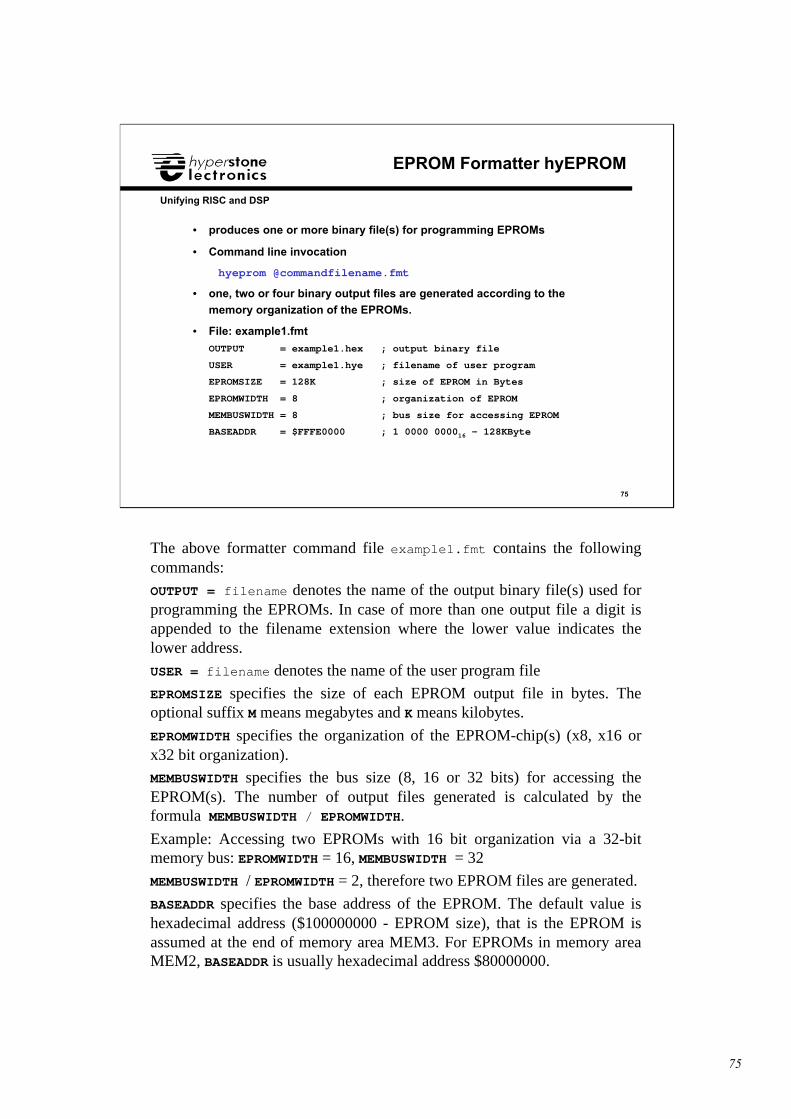
• produces one or more binary file(s) for programming EPROMs
• Command line invocation
hyeprom @commandfilename.fmt
• one, two or four binary output files are generated according to the
memory organization of the EPROMs.
• File: example1.fmt
OUTPUT = example1.hex ; output binary file
USER = example1.hye ; filename of user program
EPROMSIZE = 128K ; size of EPROM in Bytes
EPROMWIDTH = 8 ; organization of EPROM
MEMBUSWIDTH = 8 ; bus size for accessing EPROM
BASEADDR = $FFFE0000 ; 1 0000 000016 - 128KByte
The above formatter command file example1.fmt contains the followingcommands:
OUTPUT = filename denotes the name of the output binary file(s) used forprogramming the EPROMs. In case of more than one output file a digit isappended to the filename extension where the lower value indicates thelower address.
USER = filename denotes the name of the user program file
EPROMSIZE specifies the size of each EPROM output file in bytes. Theoptional suffix M means megabytes and K means kilobytes.
EPROMWIDTH specifies the organization of the EPROM-chip(s) (x8, x16 orx32 bit organization).
MEMBUSWIDTH specifies the bus size (8, 16 or 32 bits) for accessing theEPROM(s). The number of output files generated is calculated by theformula MEMBUSWIDTH / EPROMWIDTH.
Example: Accessing two EPROMs with 16 bit organization via a 32-bitmemory bus: EPROMWIDTH = 16, MEMBUSWIDTH = 32
MEMBUSWIDTH / EPROMWIDTH = 2, therefore two EPROM files are generated.
BASEADDR specifies the base address of the EPROM. The default value ishexadecimal address ($100000000 - EPROM size), that is the EPROM isassumed at the end of memory area MEM3. For EPROMs in memory areaMEM2, BASEADDR is usually hexadecimal address $80000000.
76
76
Unifying RISC and DSP
Real-Time Operating System hyRTK
❑ Real-Time Operating System hyRTK• Stack-Level Tasks• Interrupt-Level Tasks
• CreateTask
• System Calls for Delaying Tasks• Guards
• System Calls for accessing System Resources
77
77
Unifying RISC and DSP
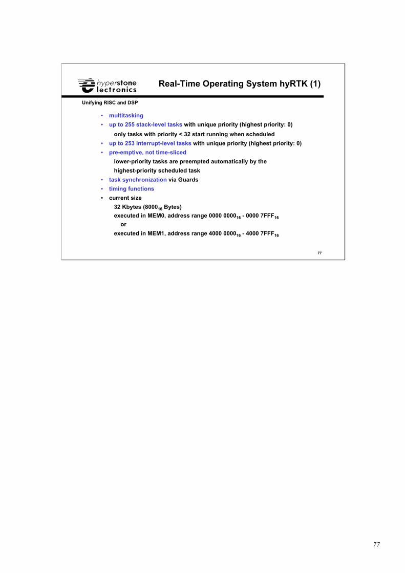
Real-Time Operating System hyRTK (1)
• multitasking
• up to 255 stack-level tasks with unique priority (highest priority: 0)
only tasks with priority < 32 start running when scheduled
• up to 253 interrupt-level tasks with unique priority (highest priority: 0)
• pre-emptive, not time-sliced
lower-priority tasks are preempted automatically by the
highest-priority scheduled task
• task synchronization via Guards
• timing functions
• current size
32 Kbytes (800016 Bytes)
executed in MEM0, address range 0000 000016 - 0000 7FFF16
or
executed in MEM1, address range 4000 000016 - 4000 7FFF16
78
78
Unifying RISC and DSP
Real-Time Operating System hyRTK (2)
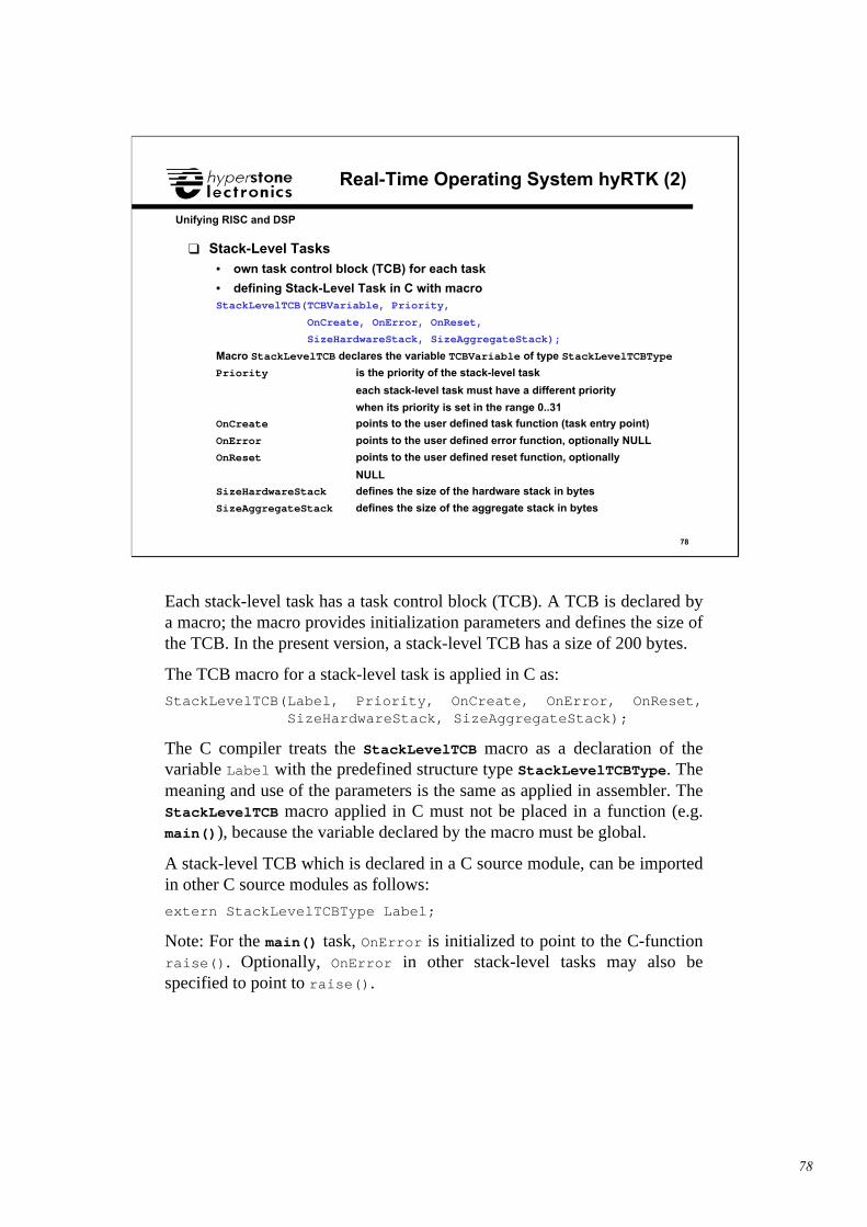
❑ Stack-Level Tasks• own task control block (TCB) for each task
• defining Stack-Level Task in C with macroStackLevelTCB(TCBVariable, Priority,
OnCreate, OnError, OnReset,
SizeHardwareStack, SizeAggregateStack);
Macro StackLevelTCB declares the variable TCBVariable of type StackLevelTCBType
Priority is the priority of the stack-level task
each stack-level task must have a different priority
when its priority is set in the range 0..31
OnCreate points to the user defined task function (task entry point)
OnError points to the user defined error function, optionally NULL
OnReset points to the user defined reset function, optionally
NULL
SizeHardwareStack defines the size of the hardware stack in bytes
SizeAggregateStack defines the size of the aggregate stack in bytes
Each stack-level task has a task control block (TCB). A TCB is declared bya macro; the macro provides initialization parameters and defines the size ofthe TCB. In the present version, a stack-level TCB has a size of 200 bytes.
The TCB macro for a stack-level task is applied in C as:
StackLevelTCB(Label, Priority, OnCreate, OnError, OnReset, SizeHardwareStack, SizeAggregateStack);
The C compiler treats the StackLevelTCB macro as a declaration of thevariable Label with the predefined structure type StackLevelTCBType. Themeaning and use of the parameters is the same as applied in assembler. TheStackLevelTCB macro applied in C must not be placed in a function (e.g.main()), because the variable declared by the macro must be global.
A stack-level TCB which is declared in a C source module, can be importedin other C source modules as follows:
extern StackLevelTCBType Label;
Note: For the main() task, OnError is initialized to point to the C-functionraise(). Optionally, OnError in other stack-level tasks may also bespecified to point to raise().
79
79
Unifying RISC and DSP
Real-Time Operating System hyRTK (3)
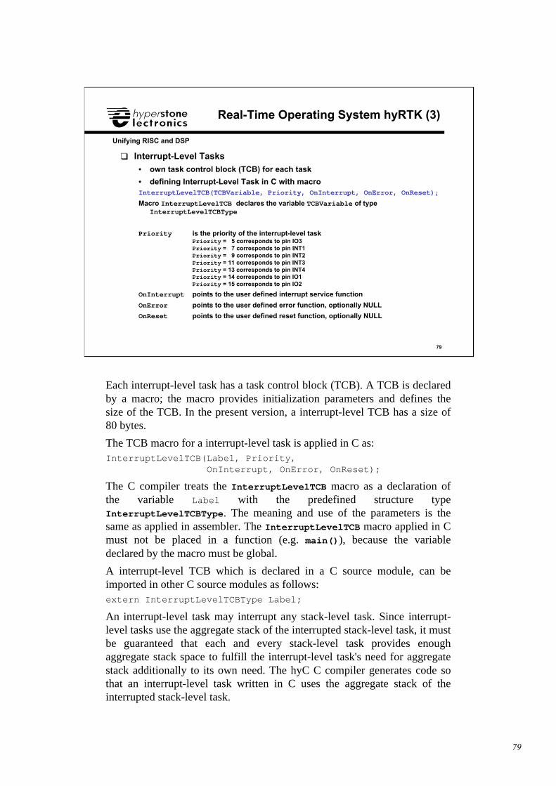
❑ Interrupt-Level Tasks• own task control block (TCB) for each task
• defining Interrupt-Level Task in C with macroInterruptLevelTCB(TCBVariable, Priority, OnInterrupt, OnError, OnReset);
Macro InterruptLevelTCB declares the variable TCBVariable of typeInterruptLevelTCBType
Priority is the priority of the interrupt-level taskPriority = 5 corresponds to pin IO3Priority = 7 corresponds to pin INT1Priority = 9 corresponds to pin INT2Priority = 11 corresponds to pin INT3Priority = 13 corresponds to pin INT4Priority = 14 corresponds to pin IO1Priority = 15 corresponds to pin IO2
OnInterrupt points to the user defined interrupt service function
OnError points to the user defined error function, optionally NULL
OnReset points to the user defined reset function, optionally NULL
Each interrupt-level task has a task control block (TCB). A TCB is declaredby a macro; the macro provides initialization parameters and defines thesize of the TCB. In the present version, a interrupt-level TCB has a size of80 bytes.
The TCB macro for a interrupt-level task is applied in C as:InterruptLevelTCB(Label, Priority, OnInterrupt, OnError, OnReset);
The C compiler treats the InterruptLevelTCB macro as a declaration ofthe variable Label with the predefined structure typeInterruptLevelTCBType. The meaning and use of the parameters is thesame as applied in assembler. The InterruptLevelTCB macro applied in Cmust not be placed in a function (e.g. main()), because the variabledeclared by the macro must be global.
A interrupt-level TCB which is declared in a C source module, can beimported in other C source modules as follows:extern InterruptLevelTCBType Label;
An interrupt-level task may interrupt any stack-level task. Since interrupt-level tasks use the aggregate stack of the interrupted stack-level task, it mustbe guaranteed that each and every stack-level task provides enoughaggregate stack space to fulfill the interrupt-level task's need for aggregatestack additionally to its own need. The hyC C compiler generates code sothat an interrupt-level task written in C uses the aggregate stack of theinterrupted stack-level task.
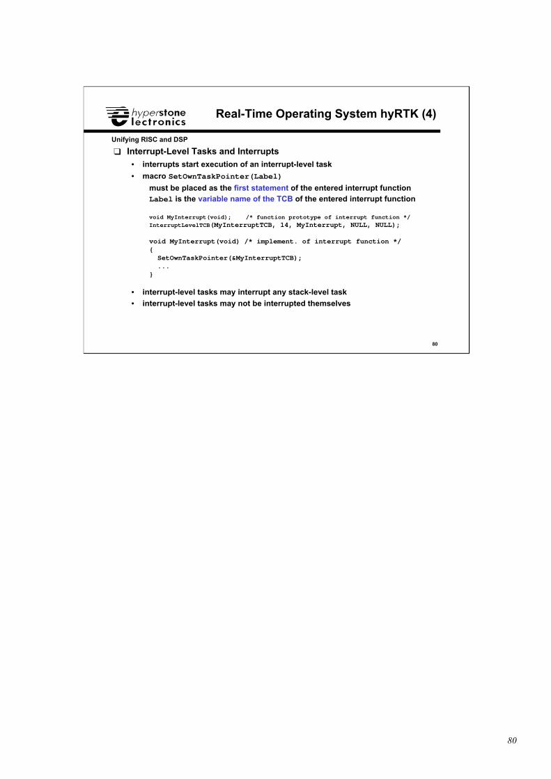
80
80
Unifying RISC and DSP
Real-Time Operating System hyRTK (4)
❑ Interrupt-Level Tasks and Interrupts• interrupts start execution of an interrupt-level task
• macro SetOwnTaskPointer(Label)
must be placed as the first statement of the entered interrupt functionLabel is the variable name of the TCB of the entered interrupt function
void MyInterrupt(void); /* function prototype of interrupt function */InterruptLevelTCB(MyInterruptTCB, 14, MyInterrupt, NULL, NULL);
void MyInterrupt(void) /* implement. of interrupt function */{ SetOwnTaskPointer(&MyInterruptTCB); ...}
• interrupt-level tasks may interrupt any stack-level task• interrupt-level tasks may not be interrupted themselves
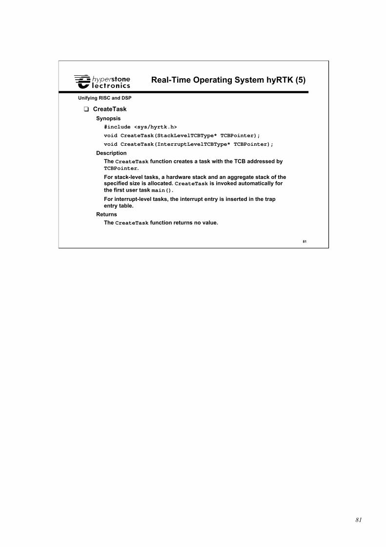
81
81
Unifying RISC and DSP
Real-Time Operating System hyRTK (5)
❑ CreateTask
Synopsis
#include <sys/hyrtk.h>
void CreateTask(StackLevelTCBType* TCBPointer);
void CreateTask(InterruptLevelTCBType* TCBPointer);
Description
The CreateTask function creates a task with the TCB addressed byTCBPointer.
For stack-level tasks, a hardware stack and an aggregate stack of thespecified size is allocated. CreateTask is invoked automatically forthe first user task main().
For interrupt-level tasks, the interrupt entry is inserted in the trapentry table.
Returns
The CreateTask function returns no value.
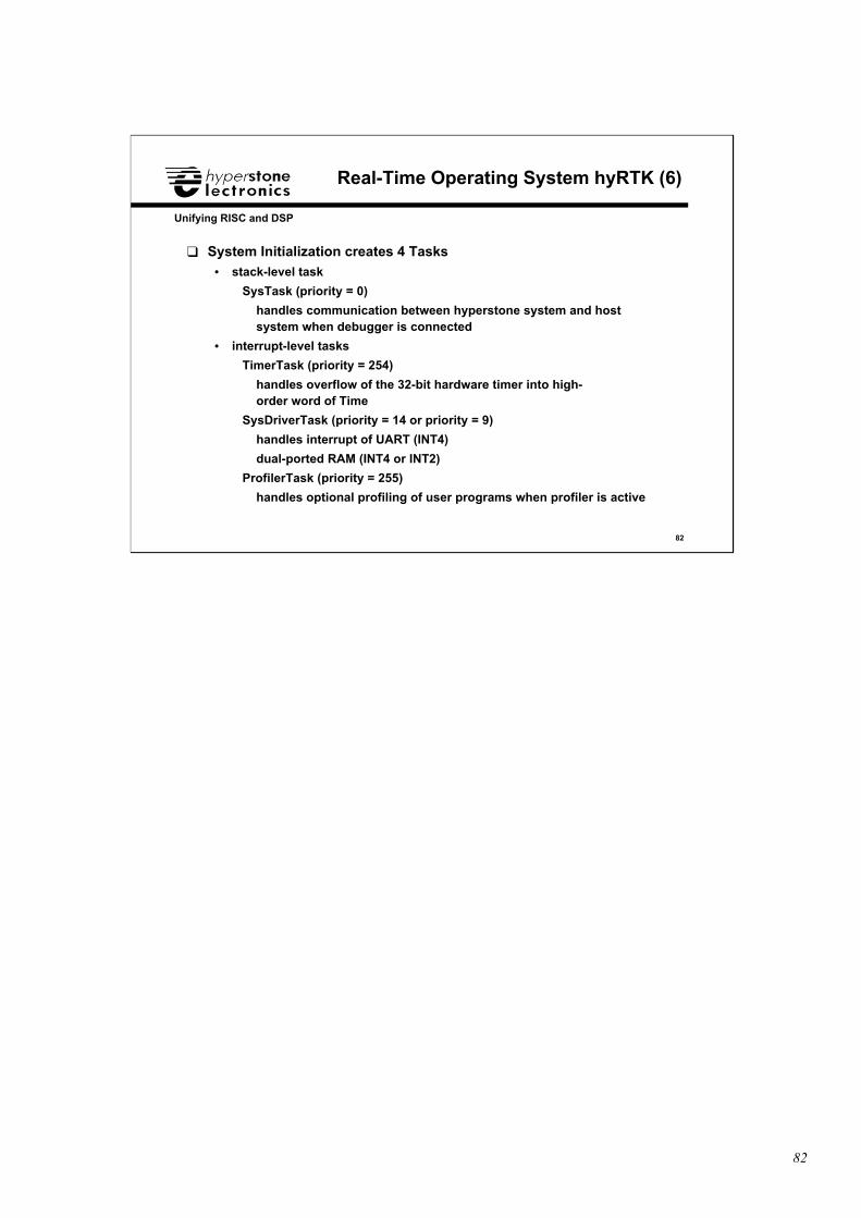
82
82
Unifying RISC and DSP
Real-Time Operating System hyRTK (6)
❑ System Initialization creates 4 Tasks• stack-level task
SysTask (priority = 0)
handles communication between hyperstone system and hostsystem when debugger is connected
• interrupt-level tasks
TimerTask (priority = 254)
handles overflow of the 32-bit hardware timer into high-order word of Time
SysDriverTask (priority = 14 or priority = 9)
handles interrupt of UART (INT4)
dual-ported RAM (INT4 or INT2)
ProfilerTask (priority = 255)
handles optional profiling of user programs when profiler is active
83
83
Unifying RISC and DSP
Real-Time Operating System hyRTK (7)
❑ GetHyTime
Synopsis
#include <sys/hyrtk.h>
signed long long int GetHyTime(void);
Description
Since system time is a value in the range of 0..263-1, the date is alsoincluded and can be extracted.
Returns The GetHyTime function returns the current system time in multiplesof 1 microsecond.

84
84
Unifying RISC and DSP
Real-Time Operating System hyRTK (8)
❑ DelayUntil
Synopsis
#include <sys/hyrtk.h>
void DelayUntil(signed long long int EventTime);
Description
The DelayUntil function suspends the calling function until theEventTime is reached.
When the EventTime is less than the current system time, the currentsystem time is placed in the EventTime.
The highest-priority scheduled stack-level task starts running.
Returns
The DelayUntil function returns no value.
85
85
Unifying RISC and DSP
Real-Time Operating System hyRTK (9)
❑ DelayBy
Synopsis
#include <sys/hyrtk.h>
void DelayBy(signed long int TimeUnits);
Description
The DelayBy function suspends the calling function for TimeUnits.
A time unit represents 1 microsecond.
A negative value of TimeUnits is treated as 0.
The highest-priority scheduled stack-level task starts running.
Returns
The DelayBy function returns no value.
86
86
Unifying RISC and DSP
Real-Time Operating System hyRTK (10)
❑ Guards• basic means to synchronize tasks
• only guard state = 0 lets a task pass and execute beyond aWaitGuard()
WaitGuardMax()
• guard state <> 0 sets any task which tries to pass viaWaitGuard()
WaitGuardMax()
to the task state waiting
• defining Guards in C with macroGuard(GuardVariable, InitialGuardState);
Macro Guard declares the variable GuardVariable with the predefinedstructure GuardType
InitialGuardState can be any C integer constant expression
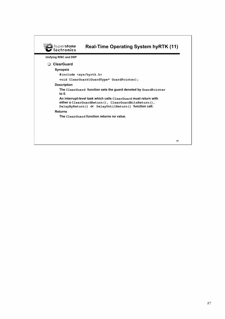
87
87
Unifying RISC and DSP
Real-Time Operating System hyRTK (11)
❑ ClearGuard
Synopsis
#include <sys/hyrtk.h>
void ClearGuard(GuardType* GuardPointer);
Description
The ClearGuard function sets the guard denoted by GuardPointerto 0.
An interrupt-level task which calls ClearGuard must return witheither a ClearGuardReturn(), ClearGuardBitsReturn(),DelayByReturn() or DelayUntilReturn() function call.
Returns
The ClearGuard function returns no value.
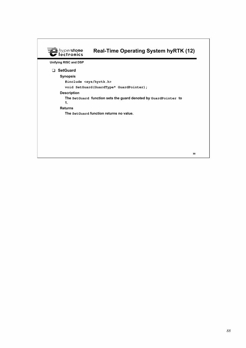
88
88
Unifying RISC and DSP
Real-Time Operating System hyRTK (12)
❑ SetGuard
Synopsis
#include <sys/hyrtk.h>
void SetGuard(GuardType* GuardPointer);
Description
The SetGuard function sets the guard denoted by GuardPointer to1.
Returns
The SetGuard function returns no value.
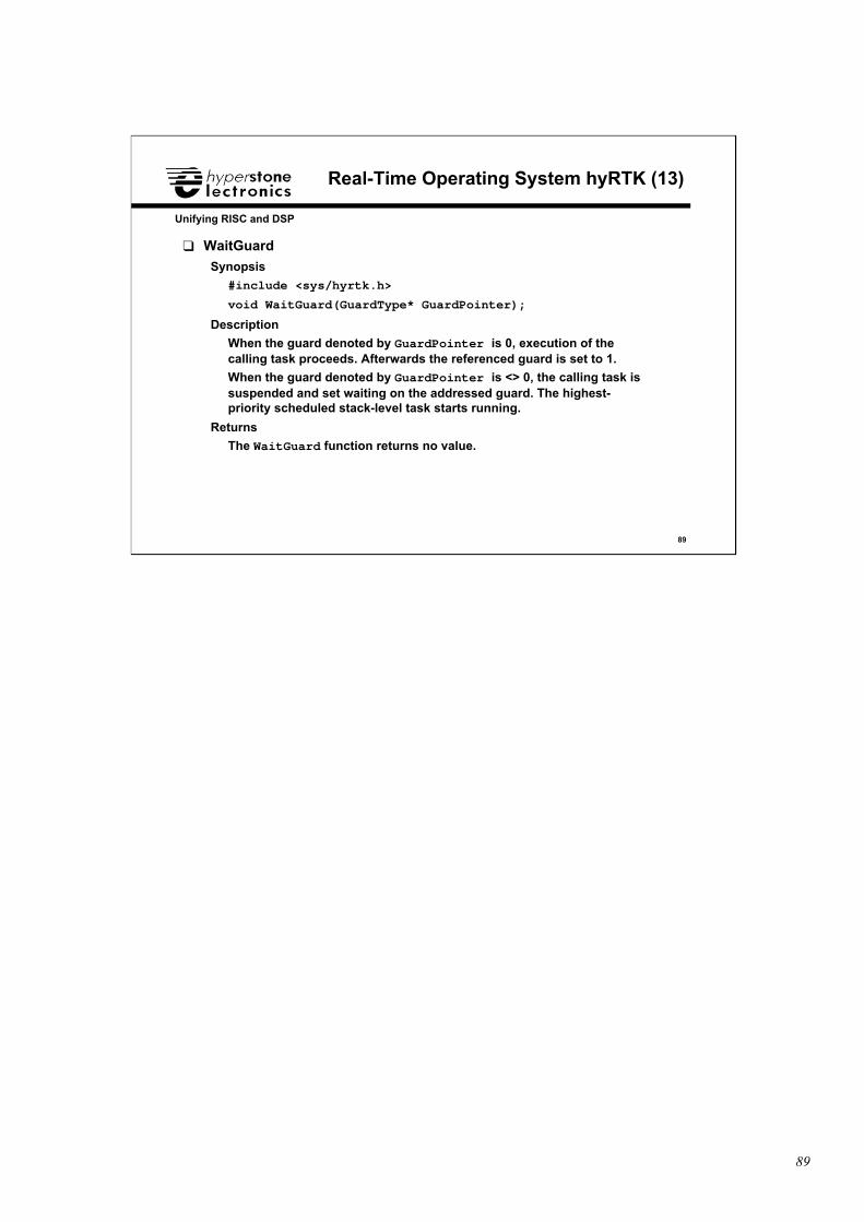
89
89
Unifying RISC and DSP
Real-Time Operating System hyRTK (13)
❑ WaitGuard
Synopsis
#include <sys/hyrtk.h>
void WaitGuard(GuardType* GuardPointer);
Description
When the guard denoted by GuardPointer is 0, execution of thecalling task proceeds. Afterwards the referenced guard is set to 1.
When the guard denoted by GuardPointer is <> 0, the calling task issuspended and set waiting on the addressed guard. The highest-priority scheduled stack-level task starts running.
Returns
The WaitGuard function returns no value.
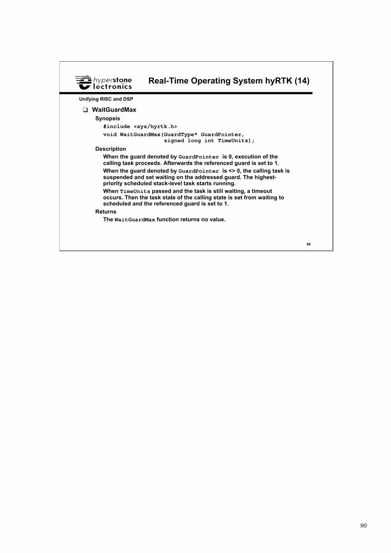
90
90
Unifying RISC and DSP
Real-Time Operating System hyRTK (14)
❑ WaitGuardMaxSynopsis
#include <sys/hyrtk.h>
void WaitGuardMax(GuardType* GuardPointer, signed long int TimeUnits);
DescriptionWhen the guard denoted by GuardPointer is 0, execution of thecalling task proceeds. Afterwards the referenced guard is set to 1.When the guard denoted by GuardPointer is <> 0, the calling task issuspended and set waiting on the addressed guard. The highest-priority scheduled stack-level task starts running.When TimeUnits passed and the task is still waiting, a timeoutoccurs. Then the task state of the calling state is set from waiting toscheduled and the referenced guard is set to 1.
ReturnsThe WaitGuardMax function returns no value.
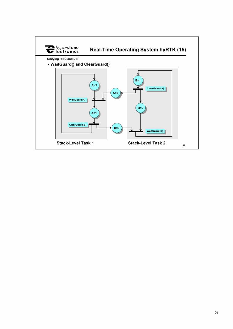
91
91
Unifying RISC and DSP
Real-Time Operating System hyRTK (15)
WaitGuard(A)WaitGuard(A)
ClearGuard(A)ClearGuard(A)
WaitGuard(B)WaitGuard(B)
ClearGuard(B)ClearGuard(B)
• WaitGuard() and ClearGuard()
Stack-Level Task 1 Stack-Level Task 2
A=?
A=0
A=1
B=0
B=1
B=?
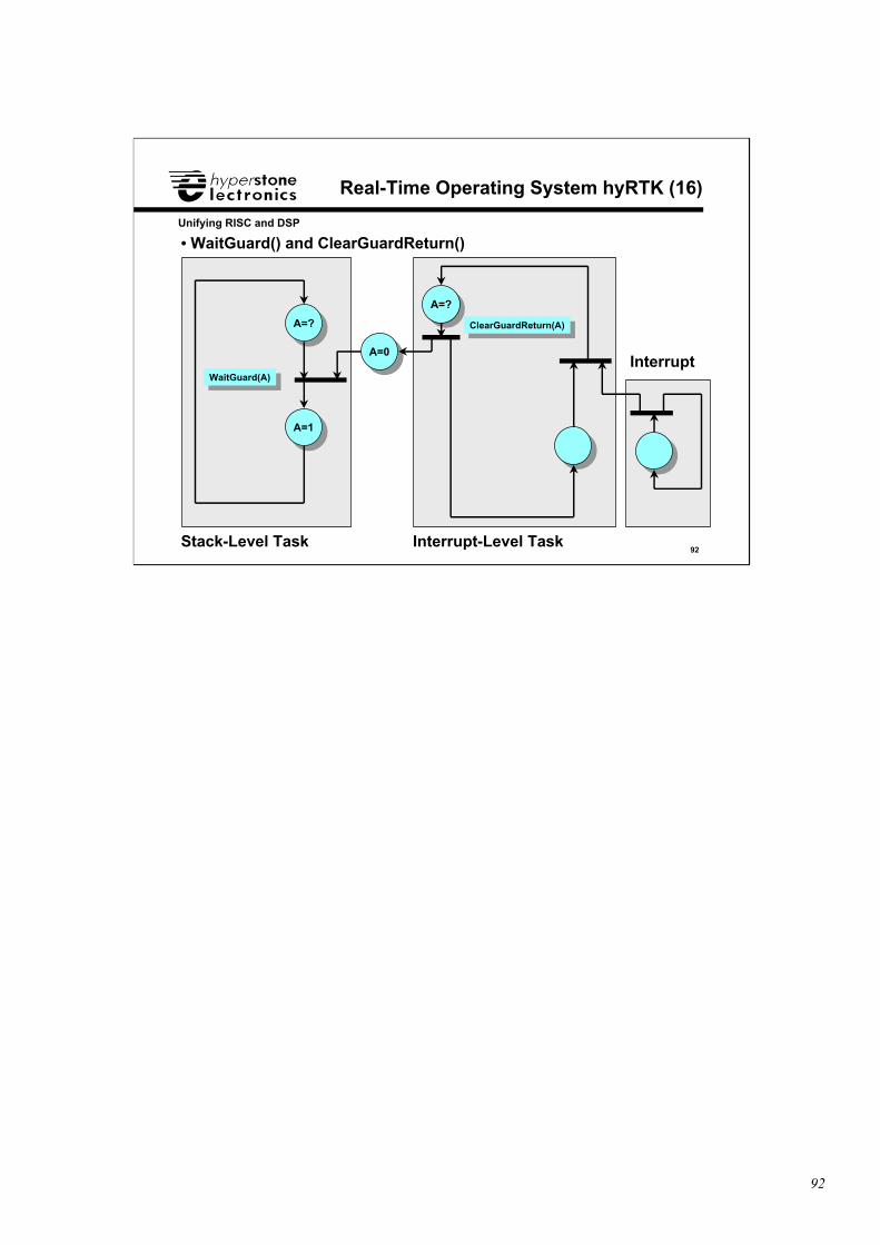
92
92
Unifying RISC and DSP
Real-Time Operating System hyRTK (16)
WaitGuard(A)WaitGuard(A)
ClearGuardReturn(A)ClearGuardReturn(A)
• WaitGuard() and ClearGuardReturn()
Stack-Level Task Interrupt-Level Task
Interrupt
A=?
A=?
A=0
A=1

93
93
Unifying RISC and DSP
Real-Time Operating System hyRTK (17)
❑ GetBCR
Synopsis
#include <sys/hyrtk.h>
unsigned long int GetBCR(void);
Returns
The GetBCR function returns the current value of the Bus ControlRegister BCR.
❑ GetMCR
Synopsis
#include <sys/hyrtk.h>
unsigned long int GetMCR(void);
Returns
The GetMCR function returns the current value of the Memory ControlRegister MCR.
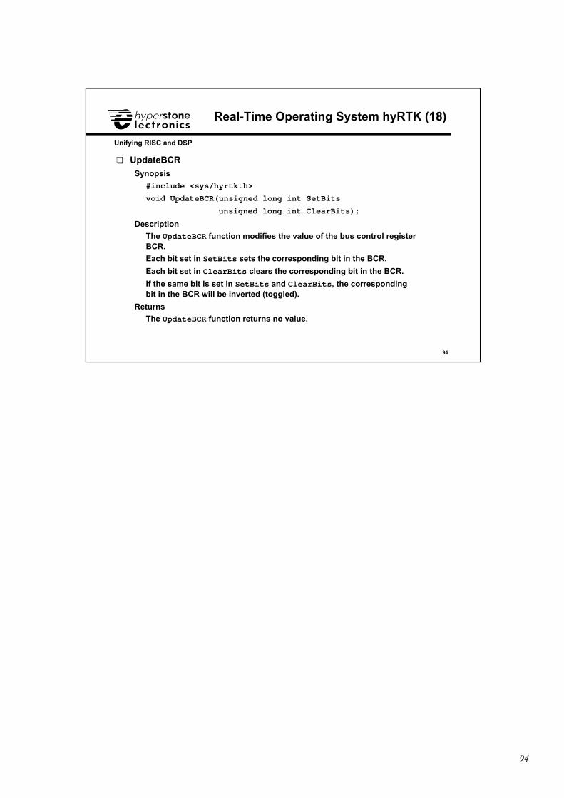
94
94
Unifying RISC and DSP
Real-Time Operating System hyRTK (18)
❑ UpdateBCR
Synopsis
#include <sys/hyrtk.h>
void UpdateBCR(unsigned long int SetBits
unsigned long int ClearBits);
Description
The UpdateBCR function modifies the value of the bus control registerBCR.
Each bit set in SetBits sets the corresponding bit in the BCR.
Each bit set in ClearBits clears the corresponding bit in the BCR.
If the same bit is set in SetBits and ClearBits, the correspondingbit in the BCR will be inverted (toggled).
Returns
The UpdateBCR function returns no value.

95
95
Unifying RISC and DSP
Real-Time Operating System hyRTK (19)
❑ UpdateMCR
Synopsis
#include <sys/hyrtk.h>
void UpdateMCR(unsigned long int SetBits
unsigned long int ClearBits);
Description
The UpdateMCR function modifies the value of the memory controlregister MCR.
Each bit set in SetBits sets the corresponding bit in the MCR.
Each bit set in ClearBits clears the corresponding bit in the MCR.
If the same bit is set in SetBits and ClearBits, the correspondingbit in the MCR will be inverted (toggled).
Returns
The UpdateMCR function returns no value.
96
96
Unifying RISC and DSP
Real-Time Operating System hyRTK (20)
❑ GetISR
Synopsis
#include <sys/hyrtk.h>
unsigned long int GetISR(void);
Returns
The GetISR function returns the current value of the Input StatusRegister ISR.
❑ GetFCR
Synopsis
#include <sys/hyrtk.h>
unsigned long int GetFCR(void);
Returns
The GetFCR function returns the current value of the Function ControlRegister FCR.

97
97
Unifying RISC and DSP
Real-Time Operating System hyRTK (21)
❑ UpdateFCR
Synopsis
#include <sys/hyrtk.h>
void UpdateFCR(unsigned long int SetBits
unsigned long int ClearBits);
Description
The UpdateFCR function modifies the value of the function controlregister FCR.
Each bit set in SetBits sets the corresponding bit in the FCR.
Each bit set in ClearBits clears the corresponding bit in the FCR.
If the same bit is set in SetBits and ClearBits, the correspondingbit in the FCR will be inverted (toggled).
Returns
The UpdateFCR function returns no value.
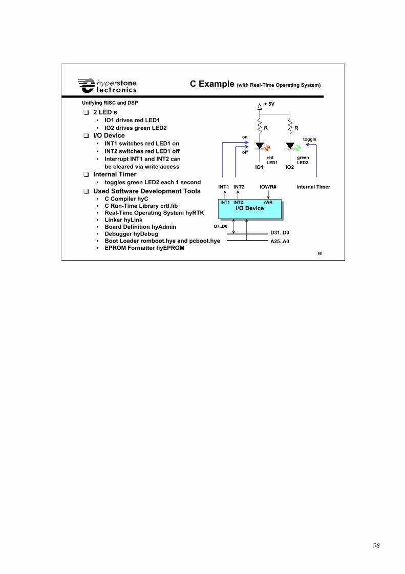
98
98
Unifying RISC and DSP
C Example (with Real-Time Operating System)
❑ 2 LED’s• IO1 drives red LED1• IO2 drives green LED2
❑ I/O Device• INT1 switches red LED1 on• INT2 switches red LED1 off• Interrupt INT1 and INT2 can
be cleared via write access❑ Internal Timer
• toggles green LED2 each 1 second
❑ Used Software Development Tools• C Compiler hyC• C Run-Time Library crtl.lib• Real-Time Operating System hyRTK• Linker hyLink• Board Definition hyAdmin• Debugger hyDebug• Boot Loader romboot.hye and pcboot.hye• EPROM Formatter hyEPROM
I/O DeviceI/O Device
IOWR#
/WR
INT1
INT1
D31..D0D7..D0
A25..A0
INT2
INT2
IO1 IO2
R R
+ 5V
internal Timer
on
off
toggle
redLED1
greenLED2
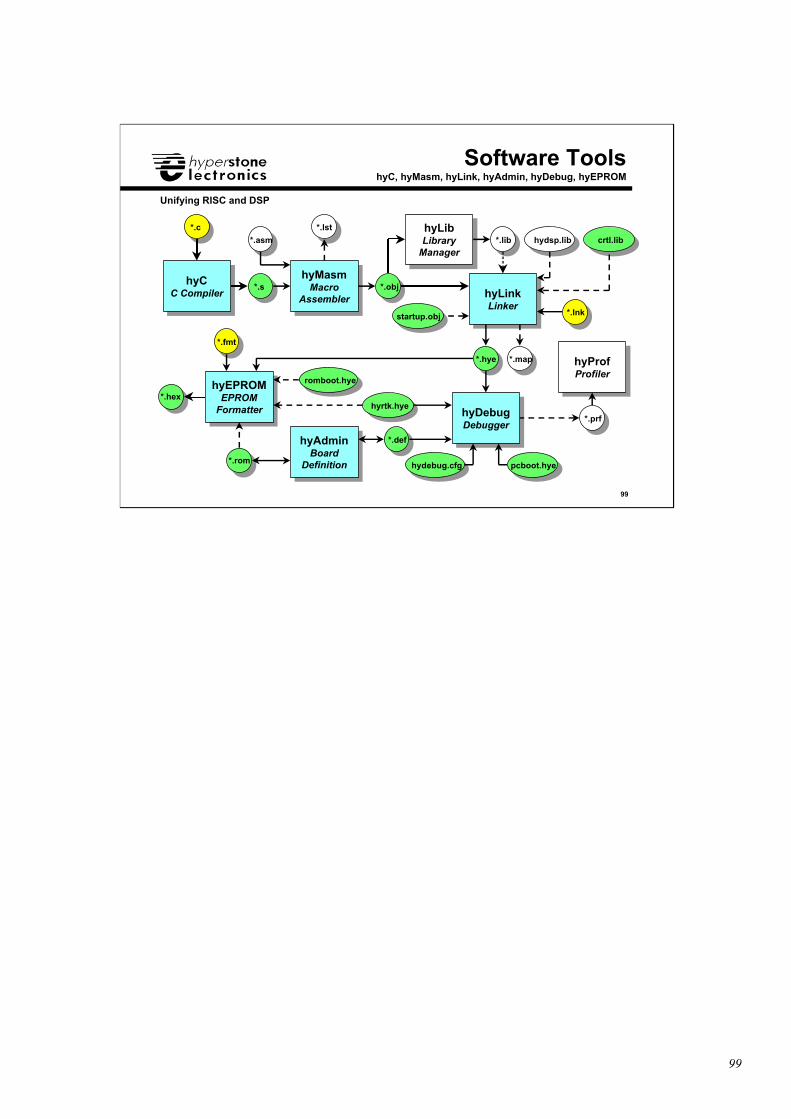
99
99
Unifying RISC and DSP
hyCC Compiler
hyCC Compiler
hyMasmMacro
Assembler
hyMasmMacro
Assembler hyLinkLinker
hyLinkLinker
hyProfProfiler
hyProfProfiler
hyEPROMEPROM
Formatter
hyEPROMEPROM
Formatter
hyAdminBoard
Definition
hyAdminBoard
Definition
hyLibLibrary
Manager
hyLibLibrary
Manager
hyDebugDebugger
hyDebugDebugger
Software ToolshyC, hyMasm, hyLink, hyAdmin, hyDebug, hyEPROM
romboot.hye
pcboot.hyehydebug.cfg
hyrtk.hye
*.c
*.s
*.asm
*.obj
*.lib
*.hye
*.prf
*.fmt
*.hex
*.rom
*.def
*.lnk
*.lst
*.map
hydsp.lib crtl.lib
startup.obj
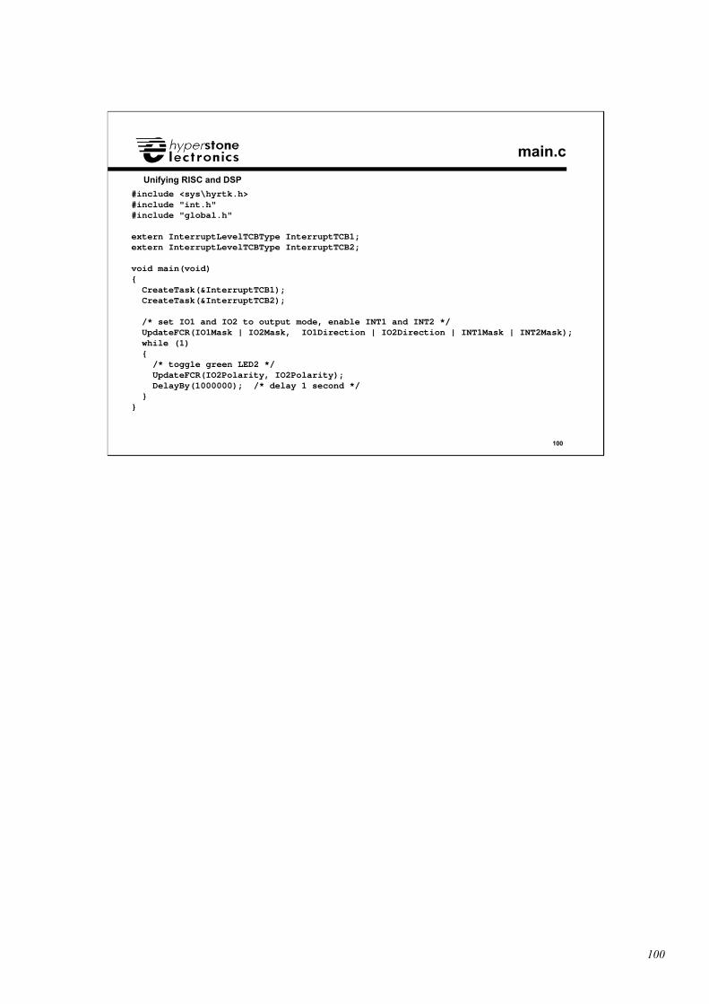
100
100
Unifying RISC and DSP
main.c
#include <sys\hyrtk.h>#include "int.h"#include "global.h"
extern InterruptLevelTCBType InterruptTCB1;extern InterruptLevelTCBType InterruptTCB2;
void main(void){ CreateTask(&InterruptTCB1); CreateTask(&InterruptTCB2);
/* set IO1 and IO2 to output mode, enable INT1 and INT2 */ UpdateFCR(IO1Mask | IO2Mask, IO1Direction | IO2Direction | INT1Mask | INT2Mask); while (1) { /* toggle green LED2 */ UpdateFCR(IO2Polarity, IO2Polarity); DelayBy(1000000); /* delay 1 second */ }}
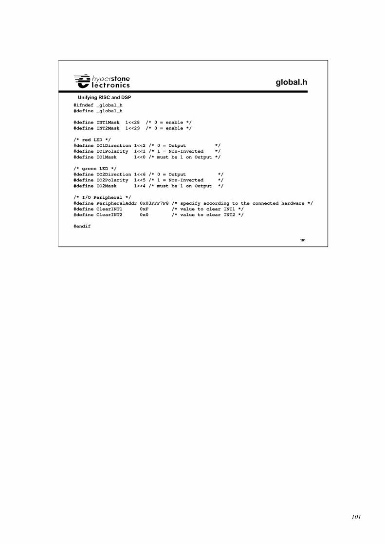
101
101
Unifying RISC and DSP
global.h
#ifndef _global_h#define _global_h
#define INT1Mask 1<<28 /* 0 = enable */#define INT2Mask 1<<29 /* 0 = enable */
/* red LED */#define IO1Direction 1<<2 /* 0 = Output */#define IO1Polarity 1<<1 /* 1 = Non-Inverted */#define IO1Mask 1<<0 /* must be 1 on Output */
/* green LED */#define IO2Direction 1<<6 /* 0 = Output */#define IO2Polarity 1<<5 /* 1 = Non-Inverted */#define IO2Mask 1<<4 /* must be 1 on Output */
/* I/O Peripheral */#define PeripheralAddr 0x03FFF7F8 /* specify according to the connected hardware */#define ClearINT1 0xF /* value to clear INT1 */#define ClearINT2 0x0 /* value to clear INT2 */
#endif
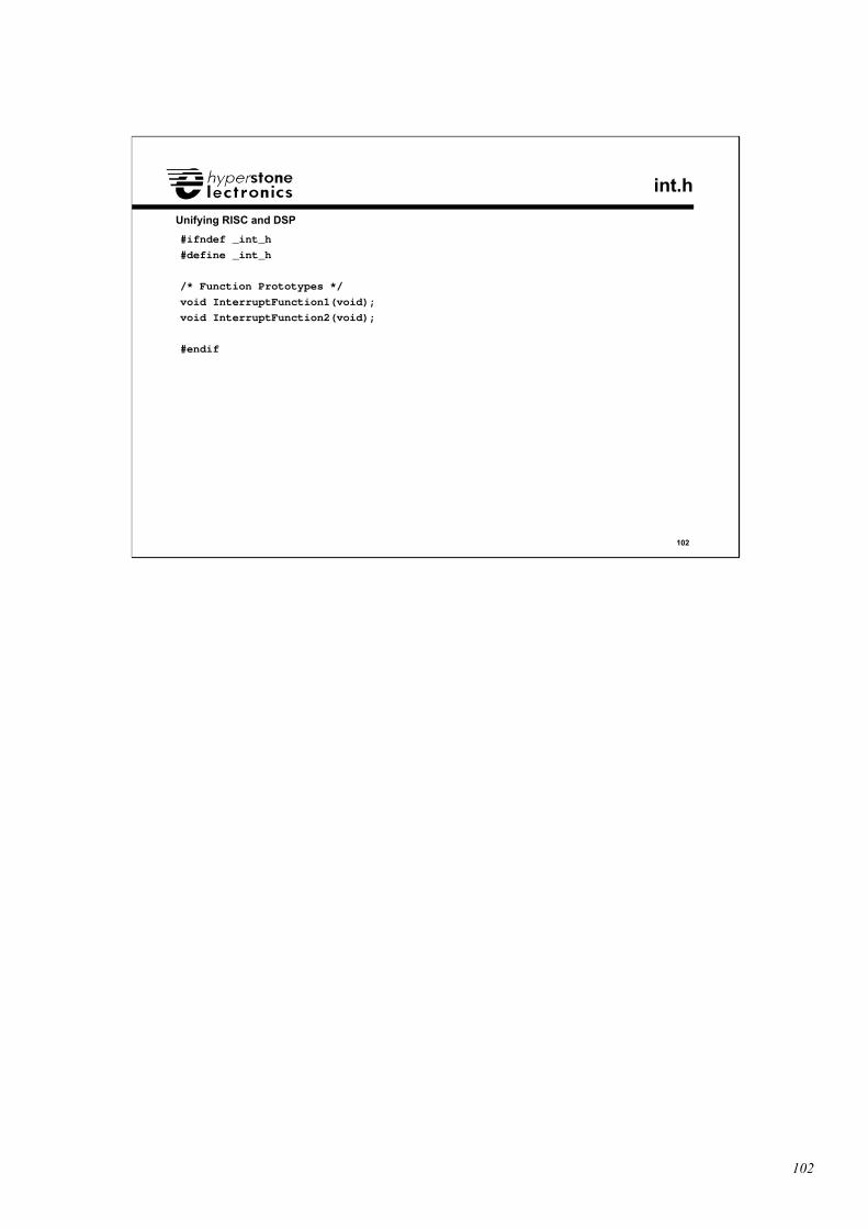
102
102
Unifying RISC and DSP
int.h
#ifndef _int_h
#define _int_h
/* Function Prototypes */
void InterruptFunction1(void);
void InterruptFunction2(void);
#endif
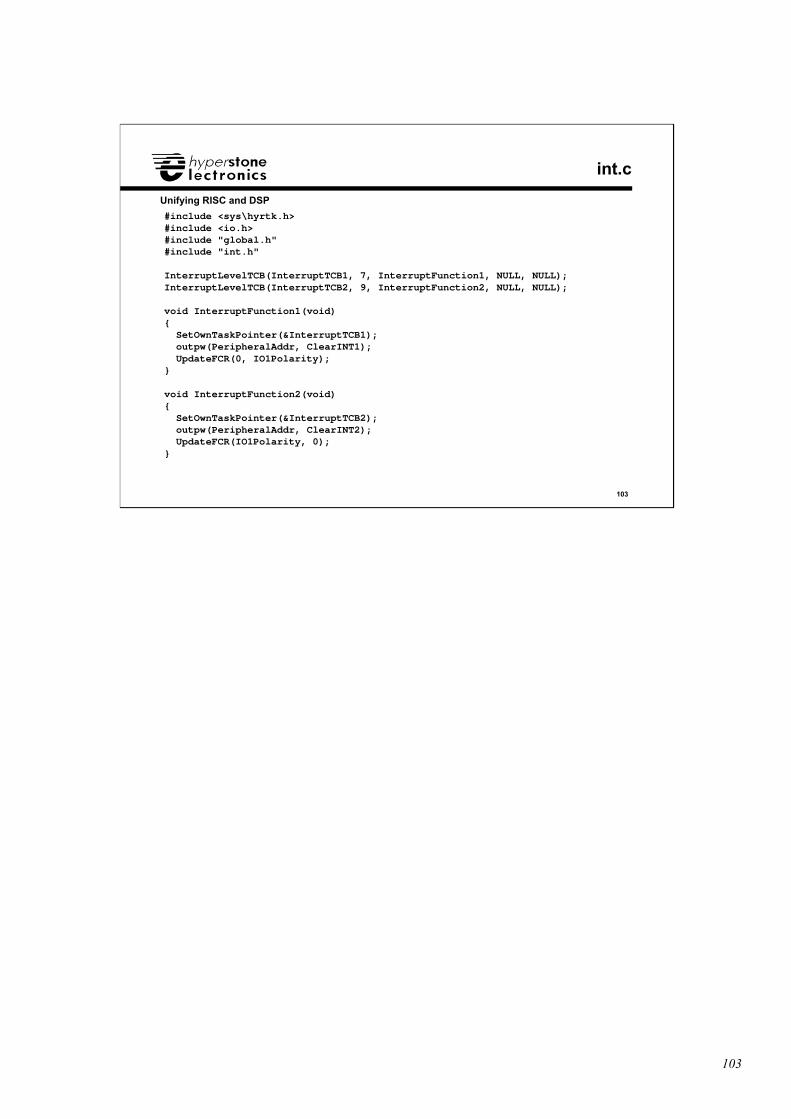
103
103
Unifying RISC and DSP
int.c
#include <sys\hyrtk.h>#include <io.h>#include "global.h"#include "int.h"
InterruptLevelTCB(InterruptTCB1, 7, InterruptFunction1, NULL, NULL);InterruptLevelTCB(InterruptTCB2, 9, InterruptFunction2, NULL, NULL);
void InterruptFunction1(void){ SetOwnTaskPointer(&InterruptTCB1); outpw(PeripheralAddr, ClearINT1); UpdateFCR(0, IO1Polarity);}
void InterruptFunction2(void){ SetOwnTaskPointer(&InterruptTCB2); outpw(PeripheralAddr, ClearINT2); UpdateFCR(IO1Polarity, 0);}
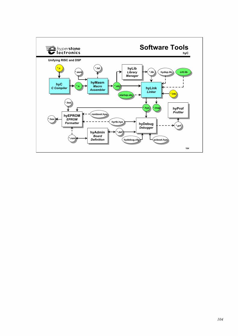
104
104
Unifying RISC and DSP
hyCC Compiler
hyCC Compiler
hyMasmMacro
Assembler
hyMasmMacro
Assembler hyLinkLinker
hyLinkLinker
hyProfProfiler
hyProfProfiler
hyEPROMEPROM
Formatter
hyEPROMEPROM
Formatter
hyAdminBoard
Definition
hyAdminBoard
Definition
hyLibLibrary
Manager
hyLibLibrary
Manager
hyDebugDebugger
hyDebugDebugger
Software ToolshyC
romboot.hye
pcboot.hyehydebug.cfg
hyrtk.hye
*.c
*.s
*.asm
*.obj
*.lib
*.hye
*.prf
*.fmt
*.hex
*.rom
*.def
*.lnk
*.lst
*.map
hydsp.lib crtl.lib
startup.obj
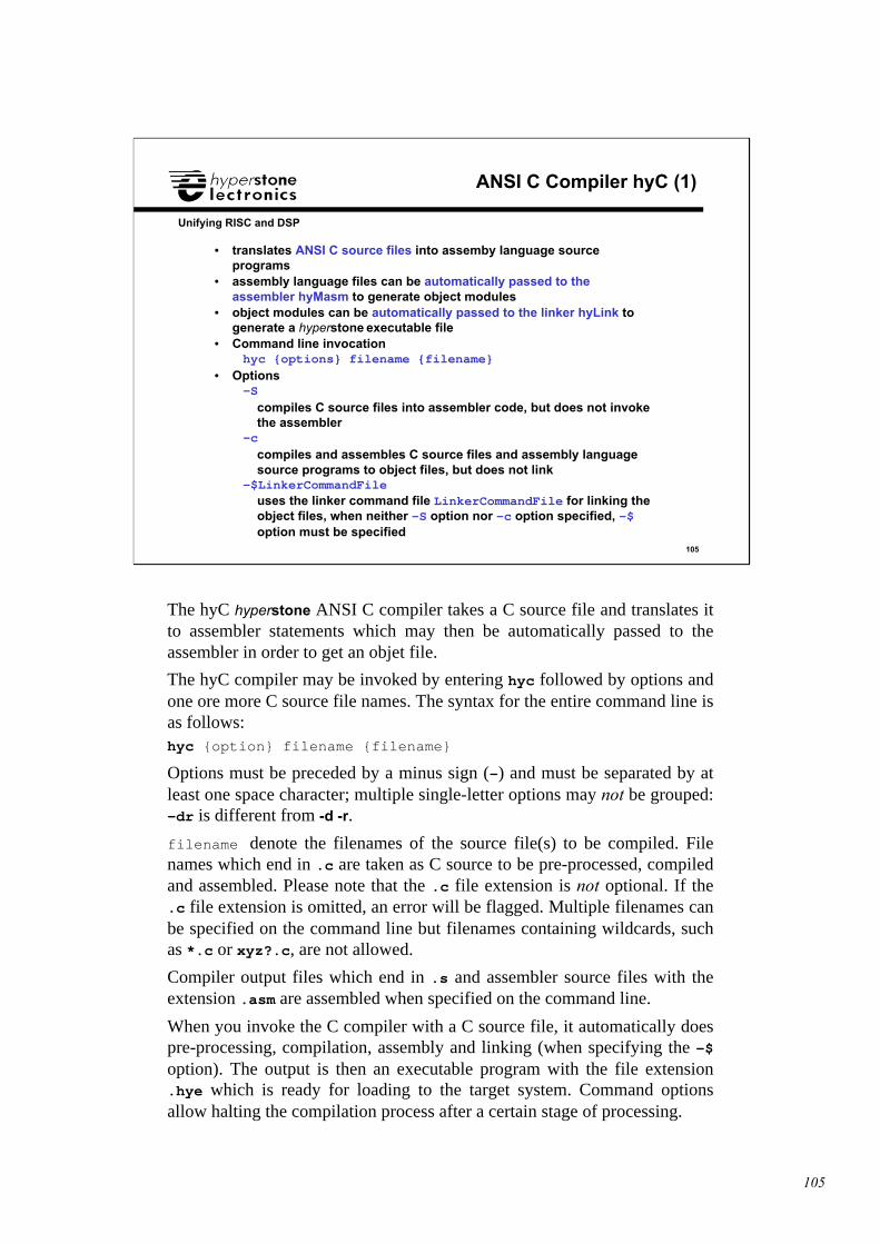
105
105
Unifying RISC and DSP
ANSI C Compiler hyC (1)
• translates ANSI C source files into assemby language sourceprograms
• assembly language files can be automatically passed to theassembler hyMasm to generate object modules
• object modules can be automatically passed to the linker hyLink togenerate a hyperstone executable file
• Command line invocationhyc {options} filename {filename}
• Options-S
compiles C source files into assembler code, but does not invokethe assembler
-ccompiles and assembles C source files and assembly languagesource programs to object files, but does not link
-$LinkerCommandFileuses the linker command file LinkerCommandFile for linking theobject files, when neither -S option nor -c option specified, -$option must be specified
The hyC hyperstone ANSI C compiler takes a C source file and translates itto assembler statements which may then be automatically passed to theassembler in order to get an objet file.
The hyC compiler may be invoked by entering hyc followed by options andone ore more C source file names. The syntax for the entire command line isas follows:hyc {option} filename {filename}
Options must be preceded by a minus sign (-) and must be separated by atleast one space character; multiple single-letter options may not be grouped:-dr is different from -d -r.
filename denote the filenames of the source file(s) to be compiled. Filenames which end in .c are taken as C source to be pre-processed, compiledand assembled. Please note that the .c file extension is not optional. If the.c file extension is omitted, an error will be flagged. Multiple filenames canbe specified on the command line but filenames containing wildcards, suchas *.c or xyz?.c, are not allowed.
Compiler output files which end in .s and assembler source files with theextension .asm are assembled when specified on the command line.
When you invoke the C compiler with a C source file, it automatically doespre-processing, compilation, assembly and linking (when specifying the -$option). The output is then an executable program with the file extension.hye which is ready for loading to the target system. Command optionsallow halting the compilation process after a certain stage of processing.
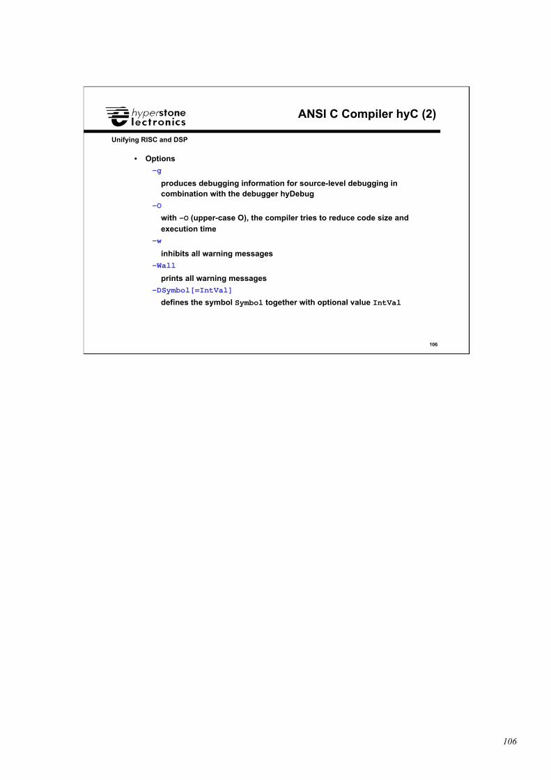
106
106
Unifying RISC and DSP
ANSI C Compiler hyC (2)
• Options
-g
produces debugging information for source-level debugging incombination with the debugger hyDebug
-O
with -O (upper-case O), the compiler tries to reduce code size andexecution time
-w
inhibits all warning messages
-Wall
prints all warning messages
-DSymbol[=IntVal]
defines the symbol Symbol together with optional value IntVal
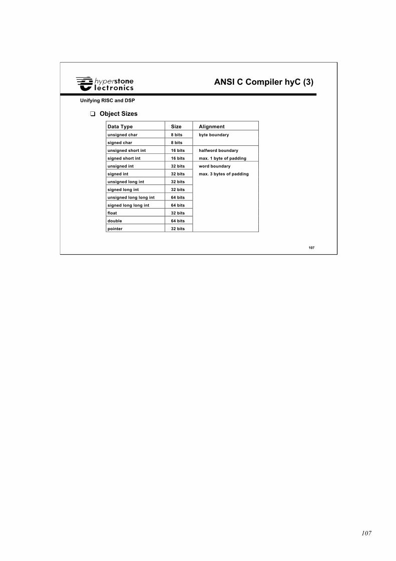
107
107
Unifying RISC and DSP
ANSI C Compiler hyC (3)
❑ Object Sizes
Data Type Size Alignment
unsigned char 8 bits byte boundary
signed char 8 bits
unsigned short int 16 bits halfword boundary
signed short int 16 bits max. 1 byte of padding
unsigned int 32 bits word boundary
signed int 32 bits max. 3 bytes of padding
unsigned long int 32 bits
signed long int 32 bits
unsigned long long int 64 bits
signed long long int 64 bits
float 32 bits
double 64 bits
pointer 32 bits
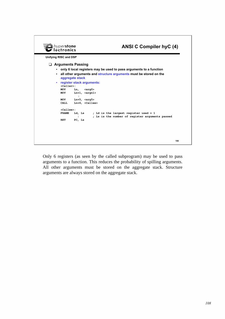
108
108
Unifying RISC and DSP
ANSI C Compiler hyC (4)
❑ Arguments Passing• only 6 local registers may be used to pass arguments to a function• all other arguments and structure arguments must be stored on the
aggregate stack• register stack arguments:
<Caller>:MOV Ln, <arg0>MOV Ln+1, <argn1>
:MOV Ln+5, <arg5>CALL Ln+6, <Callee>
<Callee>:FRAME Ld, Ls ; Ld is the largest register used + 1 : ; Ls is the number of register arguments passedRET PC, Ls
Only 6 registers (as seen by the called subprogram) may be used to passarguments to a function. This reduces the probability of spilling arguments.All other arguments must be stored on the aggregate stack. Structurearguments are always stored on the aggregate stack.
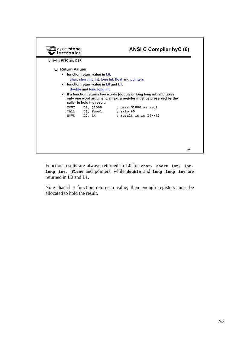
109
109
Unifying RISC and DSP
ANSI C Compiler hyC (6)
❑ Return Values• function return value in L0:
char, short int, int, long int, float and pointers
• function return value in L0 and L1:double and long long int
• If a function returns two words (double or long long int) and takesonly one word argument, an extra register must be preserved by thecaller to hold the result:MOVI L4, $1000 ; pass $1000 as arg1CALL L6, func1 ; skip L5MOVD L0, L4 ; result is in L4//L5
Function results are always returned in L0 for char, short int, int,long int, float and pointers, while double and long long int arereturned in L0 and L1.
Note that if a function returns a value, then enough registers must beallocated to hold the result.
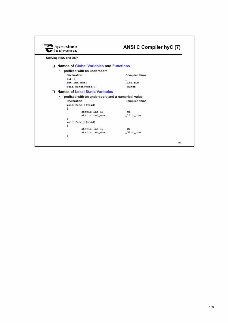
110
110
Unifying RISC and DSP
ANSI C Compiler hyC (7)
❑ Names of Global Variables and Functions• prefixed with an underscore
Declaration Compiler Nameint i; _iint int_num; _int_num
void funct(void); _funct
❑ Names of Local Static Variables• prefixed with an underscore and a numerical value
Declaration Compiler Namevoid func_a(void){
static int i; _0istatic int_num; _1int_num
}void func_b(void){
static int i; _2i static int_num; _3int_num}
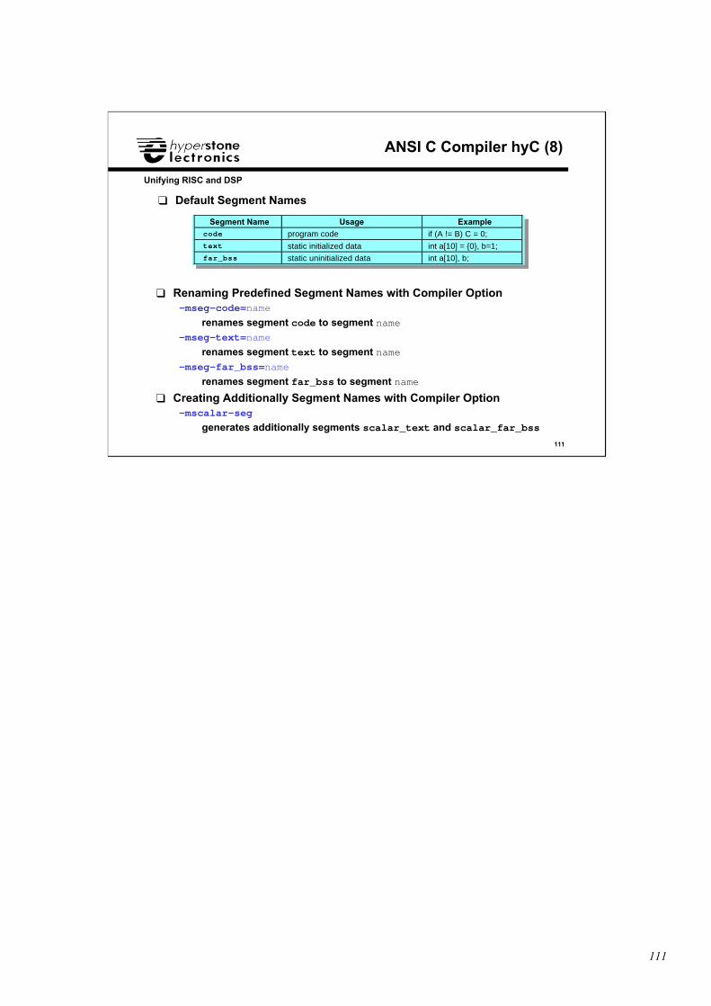
111
111
Unifying RISC and DSP
ANSI C Compiler hyC (8)
❑ Default Segment Names
❑ Renaming Predefined Segment Names with Compiler Option-mseg-code=name
renames segment code to segment name-mseg-text=name
renames segment text to segment name-mseg-far_bss=name
renames segment far_bss to segment name
❑ Creating Additionally Segment Names with Compiler Option-mscalar-seg
generates additionally segments scalar_text and scalar_far_bss
Segment Name Usage Examplecode program code if (A != B) C = 0;text static initialized data int a[10] = {0}, b=1;far_bss static uninitialized data int a[10], b;
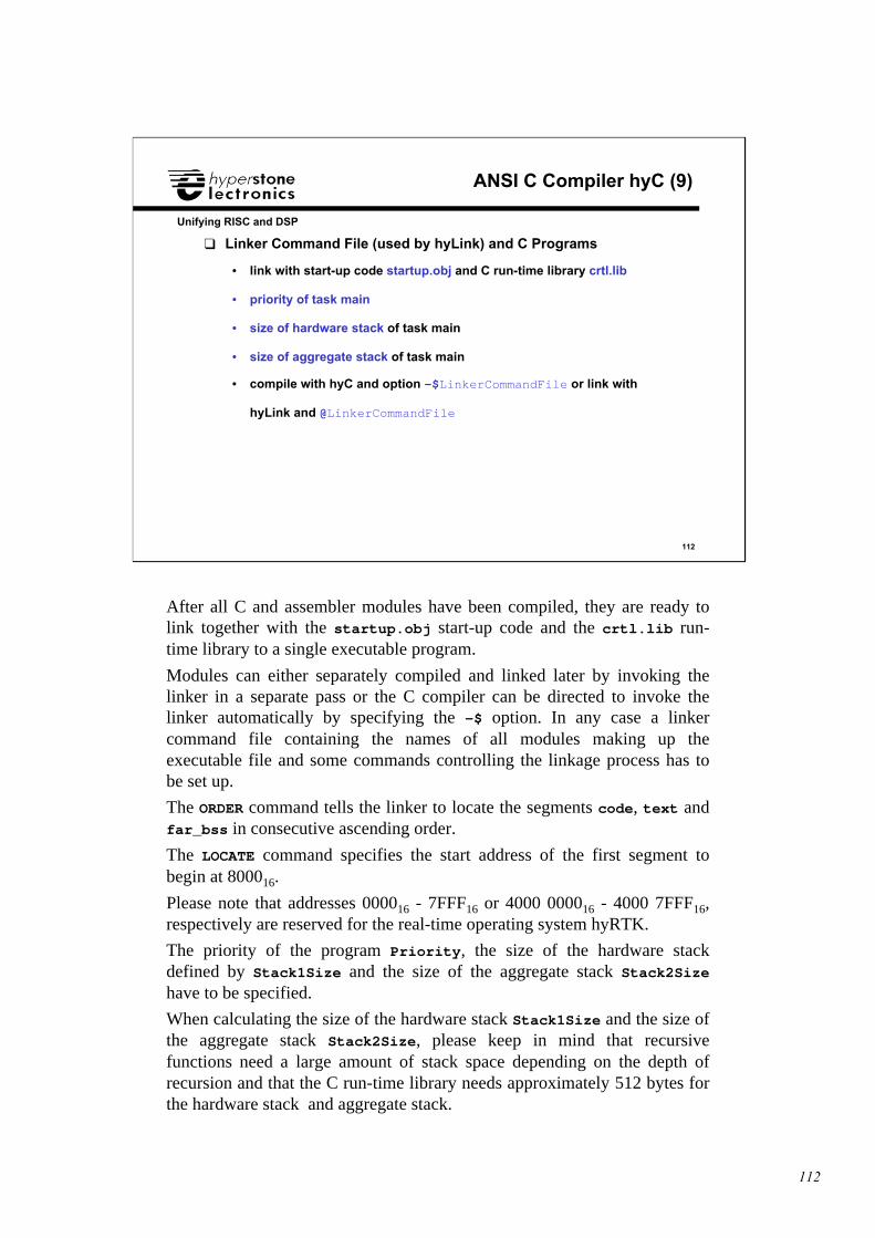
112
112
Unifying RISC and DSP
ANSI C Compiler hyC (9)
❑ Linker Command File (used by hyLink) and C Programs
• link with start-up code startup.obj and C run-time library crtl.lib
• priority of task main
• size of hardware stack of task main
• size of aggregate stack of task main
• compile with hyC and option -$LinkerCommandFile or link with
hyLink and @LinkerCommandFile
After all C and assembler modules have been compiled, they are ready tolink together with the startup.obj start-up code and the crtl.lib run-time library to a single executable program.
Modules can either separately compiled and linked later by invoking thelinker in a separate pass or the C compiler can be directed to invoke thelinker automatically by specifying the -$ option. In any case a linkercommand file containing the names of all modules making up theexecutable file and some commands controlling the linkage process has tobe set up.
The ORDER command tells the linker to locate the segments code, text andfar_bss in consecutive ascending order.
The LOCATE command specifies the start address of the first segment tobegin at 800016.
Please note that addresses 000016 - 7FFF16 or 4000 000016 - 4000 7FFF16,respectively are reserved for the real-time operating system hyRTK.
The priority of the program Priority, the size of the hardware stackdefined by Stack1Size and the size of the aggregate stack Stack2Sizehave to be specified.
When calculating the size of the hardware stack Stack1Size and the size ofthe aggregate stack Stack2Size, please keep in mind that recursivefunctions need a large amount of stack space depending on the depth ofrecursion and that the C run-time library needs approximately 512 bytes forthe hardware stack and aggregate stack.
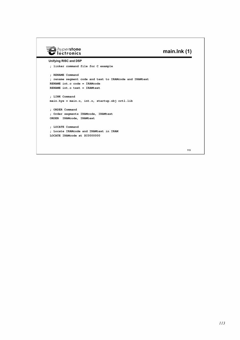
113
113
Unifying RISC and DSP
main.lnk (1)
; linker command file for C example
; RENAME Command
; rename segment code and text to IRAMcode and IRAMtext
RENAME int.o code = IRAMcode
RENAME int.o text = IRAMtext
; LINK Command
main.hye = main.o, int.o, startup.obj crtl.lib
; ORDER Command
; Order segments IRAMcode, IRAMtext
ORDER IRAMcode, IRAMtext
; LOCATE Command
; Locate IRAMcode and IRAMtext in IRAM
LOCATE IRAMcode at $C0000000
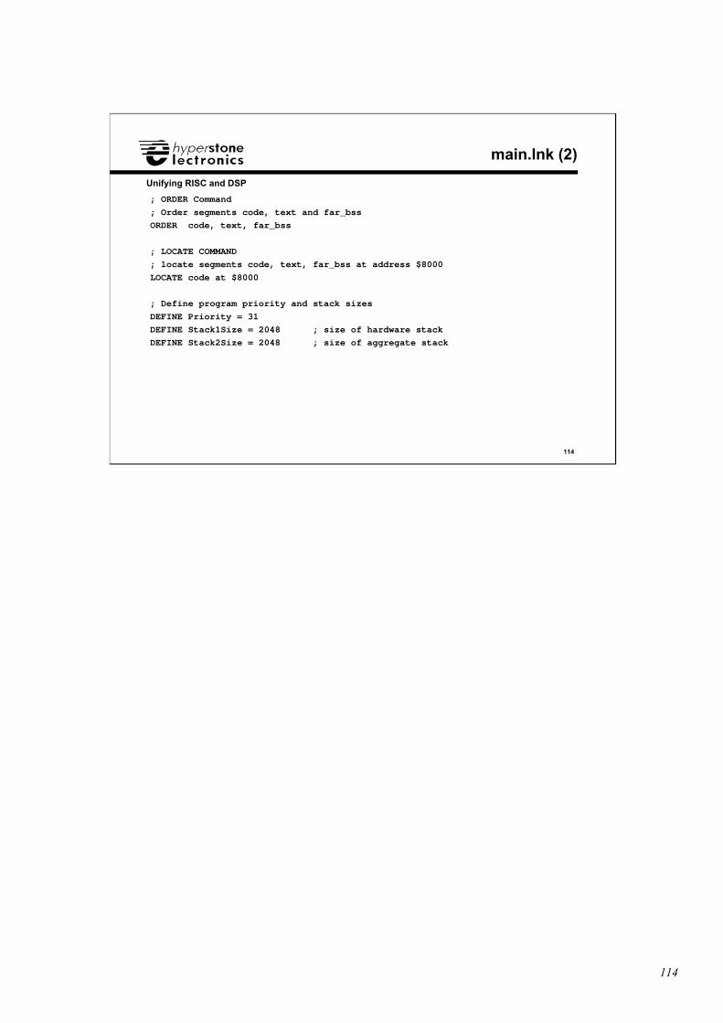
114
114
Unifying RISC and DSP
main.lnk (2)
; ORDER Command
; Order segments code, text and far_bss
ORDER code, text, far_bss
; LOCATE COMMAND
; locate segments code, text, far_bss at address $8000
LOCATE code at $8000
; Define program priority and stack sizes
DEFINE Priority = 31
DEFINE Stack1Size = 2048 ; size of hardware stack
DEFINE Stack2Size = 2048 ; size of aggregate stack
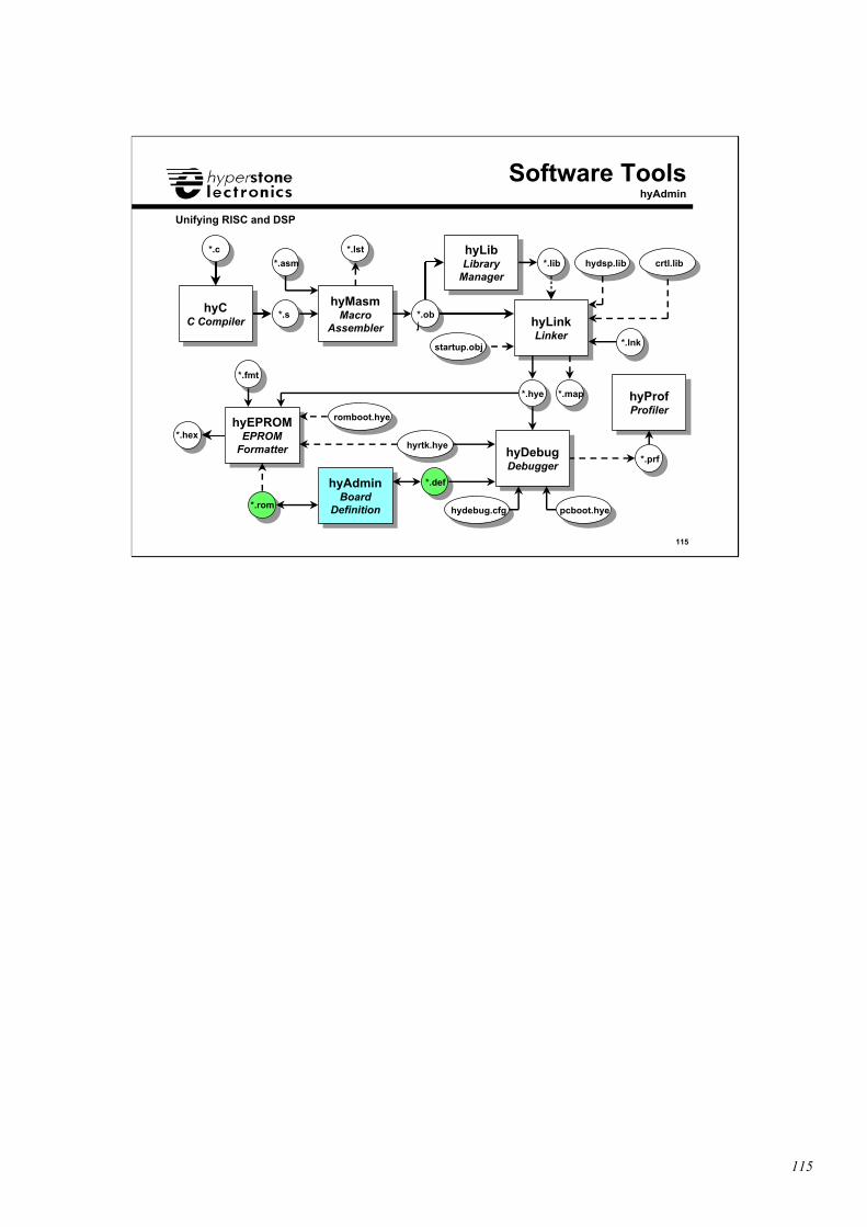
115
115
Unifying RISC and DSP
hyCC Compiler
hyCC Compiler
hyMasmMacro
Assembler
hyMasmMacro
Assembler hyLinkLinker
hyLinkLinker
hyProfProfiler
hyProfProfiler
hyEPROMEPROM
Formatter
hyEPROMEPROM
Formatter
hyAdminBoard
Definition
hyAdminBoard
Definition
hyLibLibrary
Manager
hyLibLibrary
Manager
hyDebugDebugger
hyDebugDebugger
Software ToolshyAdmin
romboot.hye
pcboot.hyehydebug.cfg
hyrtk.hye
*.c
*.s
*.asm
*.obj
*.lib
*.hye
*.prf
*.fmt
*.hex
*.rom
*.def
*.lnk
*.lst
*.map
hydsp.lib crtl.lib
startup.obj
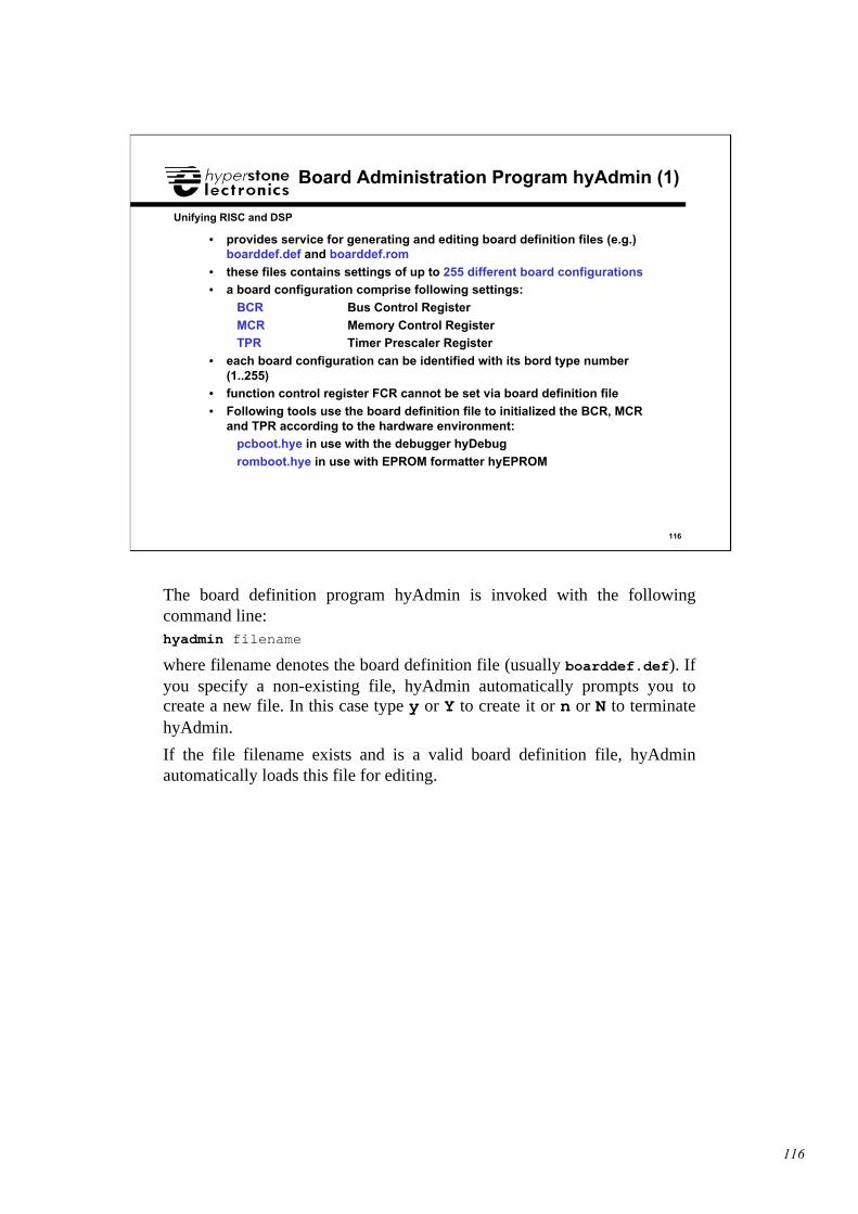
116
116
Unifying RISC and DSP
Board Administration Program hyAdmin (1)
• provides service for generating and editing board definition files (e.g.)boarddef.def and boarddef.rom
• these files contains settings of up to 255 different board configurations• a board configuration comprise following settings:
BCR Bus Control Register
MCR Memory Control RegisterTPR Timer Prescaler Register
• each board configuration can be identified with its bord type number(1..255)
• function control register FCR cannot be set via board definition file
• Following tools use the board definition file to initialized the BCR, MCRand TPR according to the hardware environment:
pcboot.hye in use with the debugger hyDebug
romboot.hye in use with EPROM formatter hyEPROM
The board definition program hyAdmin is invoked with the followingcommand line:hyadmin filename
where filename denotes the board definition file (usually boarddef.def). Ifyou specify a non-existing file, hyAdmin automatically prompts you tocreate a new file. In this case type y or Y to create it or n or N to terminatehyAdmin.
If the file filename exists and is a valid board definition file, hyAdminautomatically loads this file for editing.
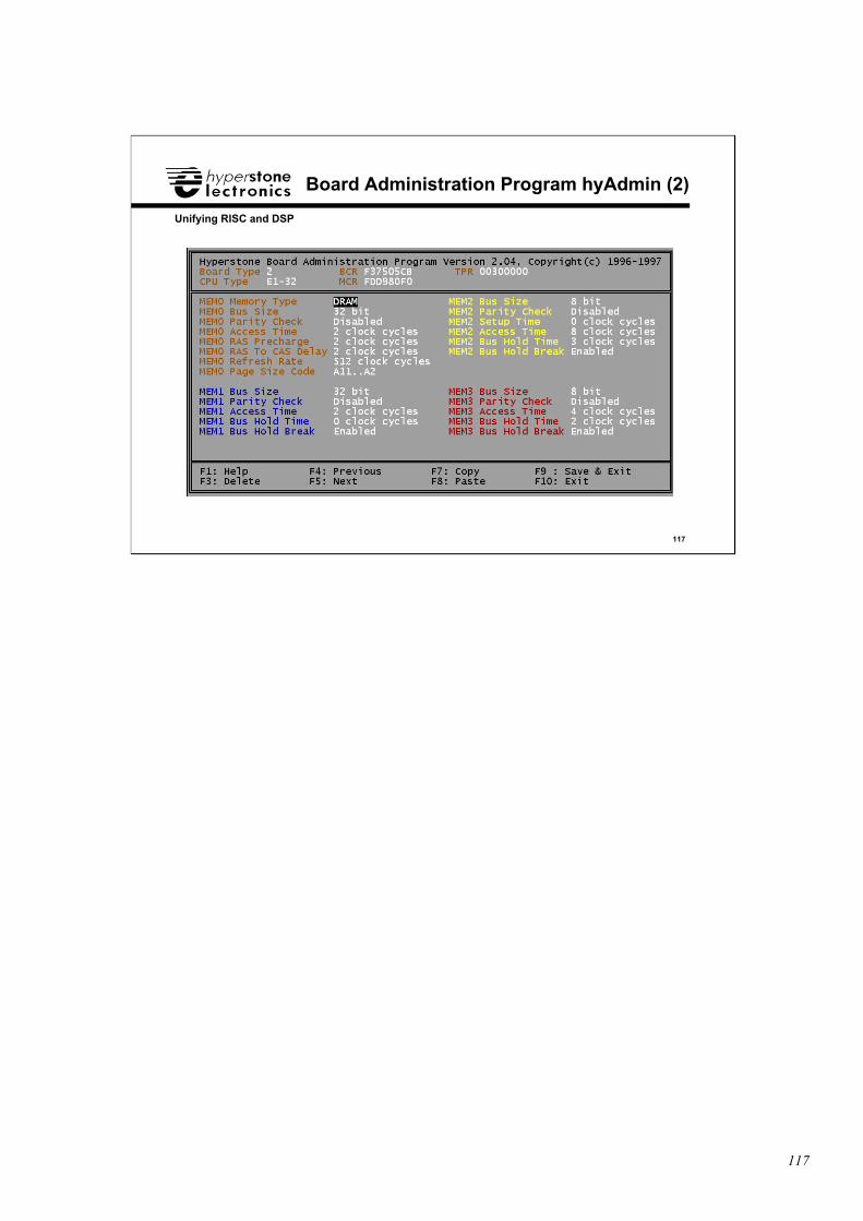
117
117
Unifying RISC and DSP
Board Administration Program hyAdmin (2)
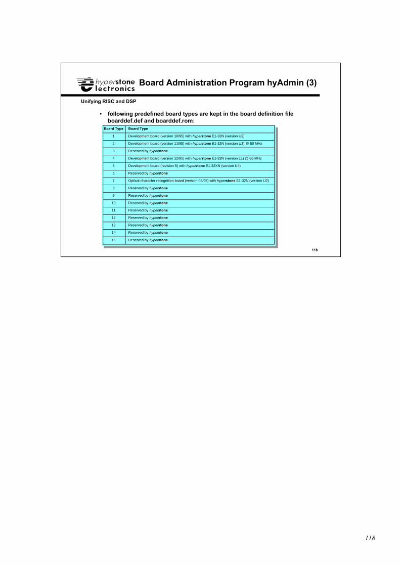
118
118
Unifying RISC and DSP
Board Administration Program hyAdmin (3)
• following predefined board types are kept in the board definition fileboarddef.def and boarddef.rom:
Board Type Board Type
1 Development board (version 10/95) with hyperstone E1-32N (version U2)
2 Development board (version 11/95) with hyperstone E1-32N (version U3) @ 50 MHz
3 Reserved by hyperstone
4 Development board (version 12/95) with hyperstone E1-32N (version LL) @ 66 MHz
5 Development board (revision 5) with hyperstone E1-32XN (version U4)
6 Reserved by hyperstone
7 Optical character recognition board (version 08/95) with hyperstone E1-32N (version U2)
8 Reserved by hyperstone
9 Reserved by hyperstone
10 Reserved by hyperstone
11 Reserved by hyperstone
12 Reserved by hyperstone
13 Reserved by hyperstone
14 Reserved by hyperstone
15 Reserved by hyperstone
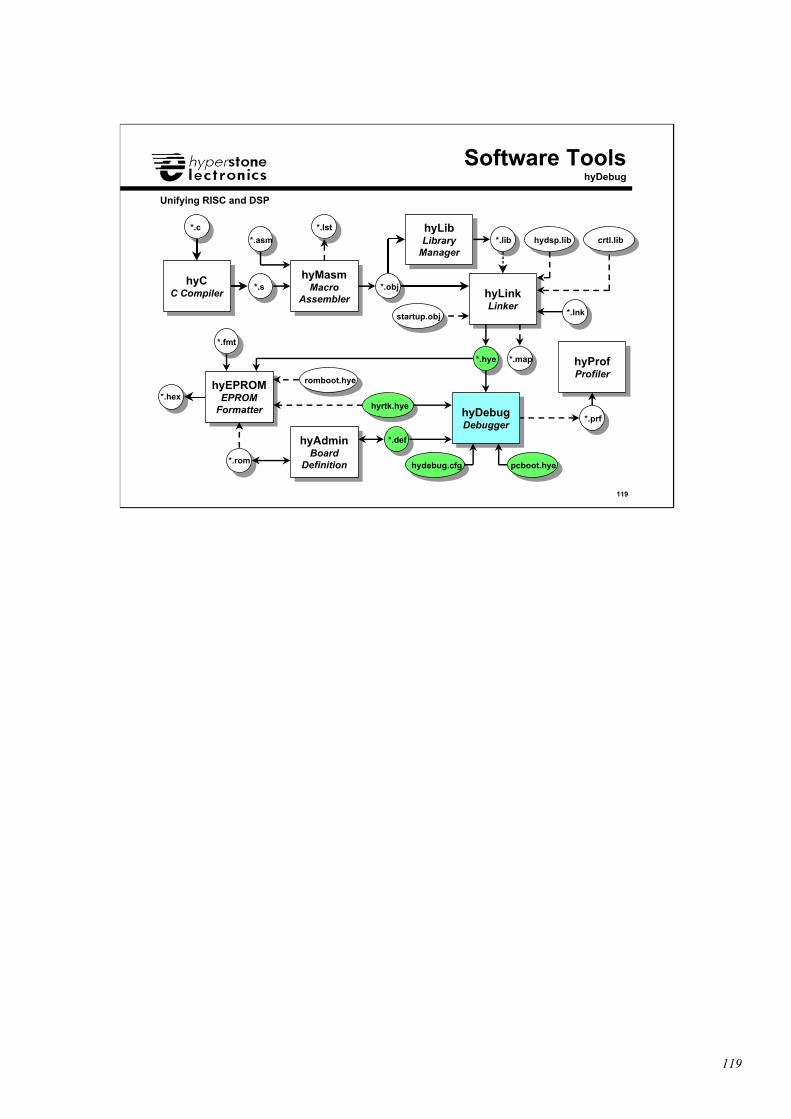
119
119
Unifying RISC and DSP
hyCC Compiler
hyCC Compiler
hyMasmMacro
Assembler
hyMasmMacro
Assembler hyLinkLinker
hyLinkLinker
hyProfProfiler
hyProfProfiler
hyEPROMEPROM
Formatter
hyEPROMEPROM
Formatter
hyAdminBoard
Definition
hyAdminBoard
Definition
hyLibLibrary
Manager
hyLibLibrary
Manager
hyDebugDebugger
hyDebugDebugger
Software ToolshyDebug
romboot.hye
pcboot.hyehydebug.cfg
hyrtk.hye
*.c
*.s
*.asm
*.obj
*.lib
*.hye
*.prf
*.fmt
*.hex
*.rom
*.def
*.lnk
*.lst
*.map
hydsp.lib crtl.lib
startup.obj
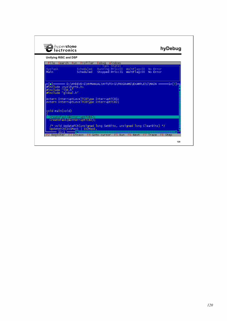
120
120
Unifying RISC and DSP
hyDebug
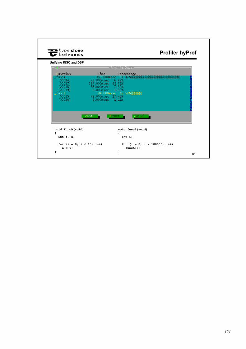
121
121
Unifying RISC and DSP
Profiler hyProf
void funcA(void){ int i, a;
for (i = 0; i < 10; i++) a = 0;}
void funcB(void){ int i;
for (i = 0; i < 100000; i++) funcA();}
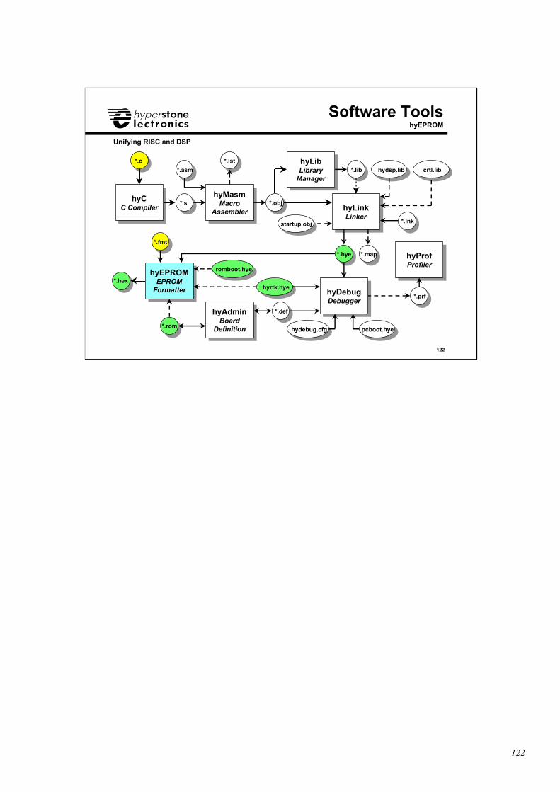
122
122
Unifying RISC and DSP
hyCC Compiler
hyCC Compiler
hyMasmMacro
Assembler
hyMasmMacro
Assembler hyLinkLinker
hyLinkLinker
hyProfProfiler
hyProfProfiler
hyEPROMEPROM
Formatter
hyEPROMEPROM
Formatter
hyAdminBoard
Definition
hyAdminBoard
Definition
hyLibLibrary
Manager
hyLibLibrary
Manager
hyDebugDebugger
hyDebugDebugger
Software ToolshyEPROM
romboot.hye
pcboot.hyehydebug.cfg
hyrtk.hye
*.c
*.s
*.asm
*.obj
*.lib
*.hye
*.prf
*.fmt
*.hex
*.rom
*.def
*.lnk
*.lst
*.map
hydsp.lib crtl.lib
startup.obj
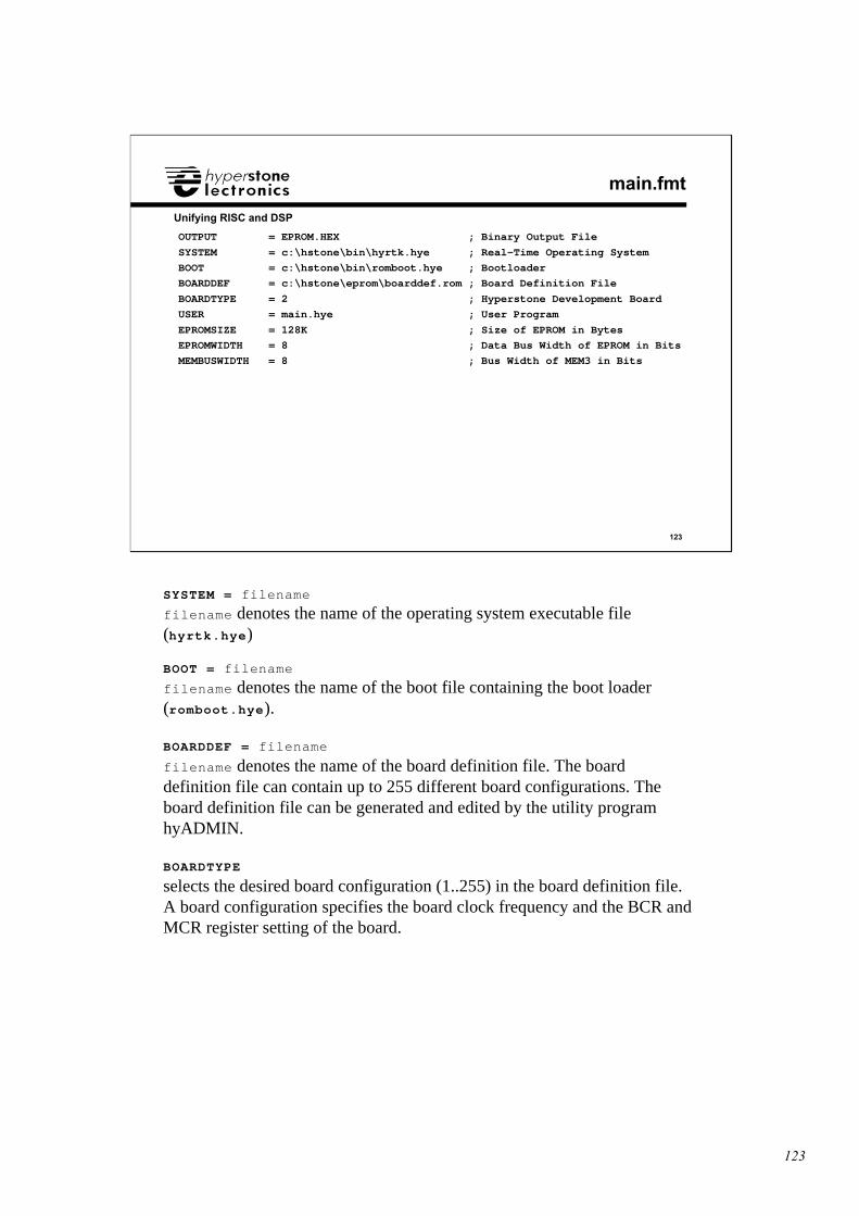
123
123
Unifying RISC and DSP
main.fmt
OUTPUT = EPROM.HEX ; Binary Output File
SYSTEM = c:\hstone\bin\hyrtk.hye ; Real-Time Operating System
BOOT = c:\hstone\bin\romboot.hye ; Bootloader
BOARDDEF = c:\hstone\eprom\boarddef.rom ; Board Definition File
BOARDTYPE = 2 ; Hyperstone Development Board
USER = main.hye ; User Program
EPROMSIZE = 128K ; Size of EPROM in Bytes
EPROMWIDTH = 8 ; Data Bus Width of EPROM in Bits
MEMBUSWIDTH = 8 ; Bus Width of MEM3 in Bits
SYSTEM = filename
filename denotes the name of the operating system executable file(hyrtk.hye)
BOOT = filename
filename denotes the name of the boot file containing the boot loader(romboot.hye).
BOARDDEF = filename
filename denotes the name of the board definition file. The boarddefinition file can contain up to 255 different board configurations. Theboard definition file can be generated and edited by the utility programhyADMIN.
BOARDTYPE
selects the desired board configuration (1..255) in the board definition file.A board configuration specifies the board clock frequency and the BCR andMCR register setting of the board.
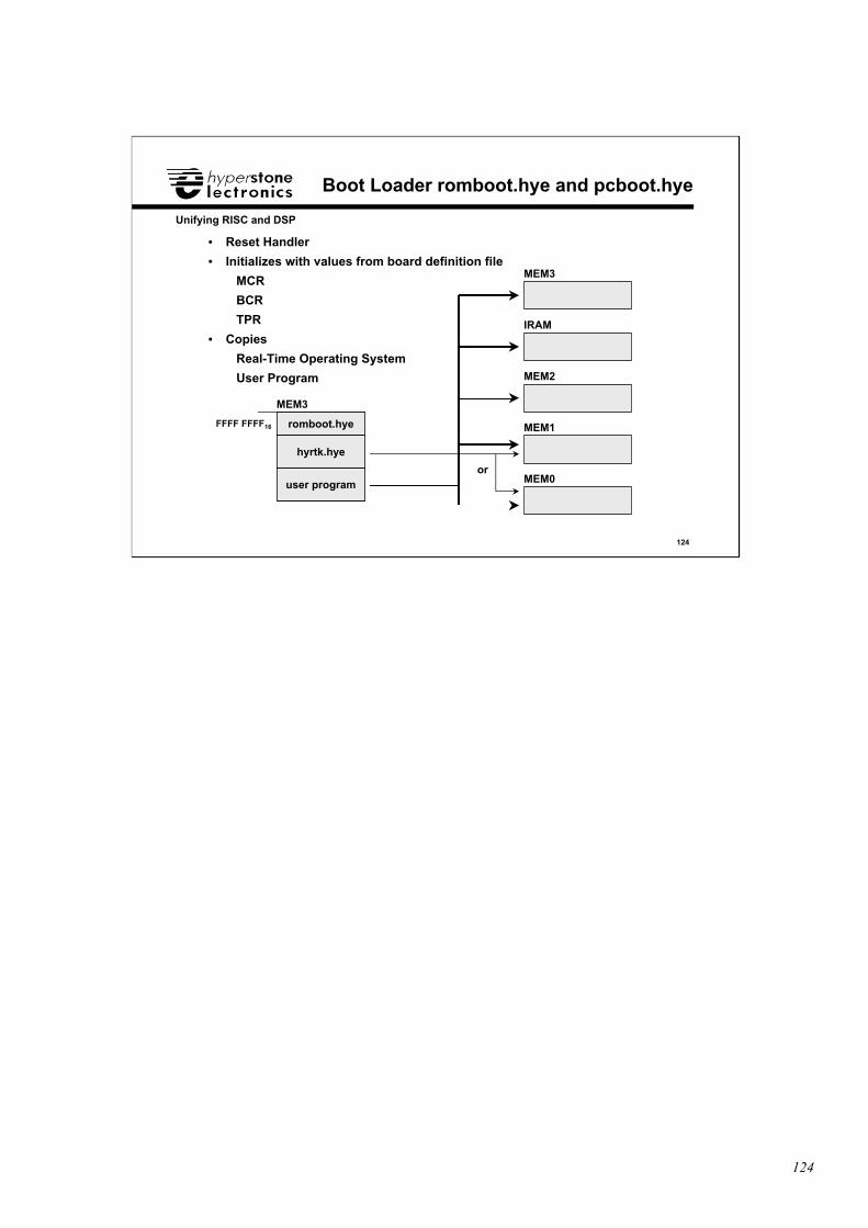
124
124
Unifying RISC and DSP
Boot Loader romboot.hye and pcboot.hye
• Reset Handler
• Initializes with values from board definition file
MCR
BCR
TPR
• Copies
Real-Time Operating System
User Program
FFFF FFFF16 romboot.hye
hyrtk.hye
user program
MEM3
MEM3
IRAM
MEM2
MEM1
MEM0or
125
125
Unifying RISC and DSP
DSP Unit
❑ DSP Unit• ALU and DSP Unit• Parallelism ALU - DSP
• Example Dot Product
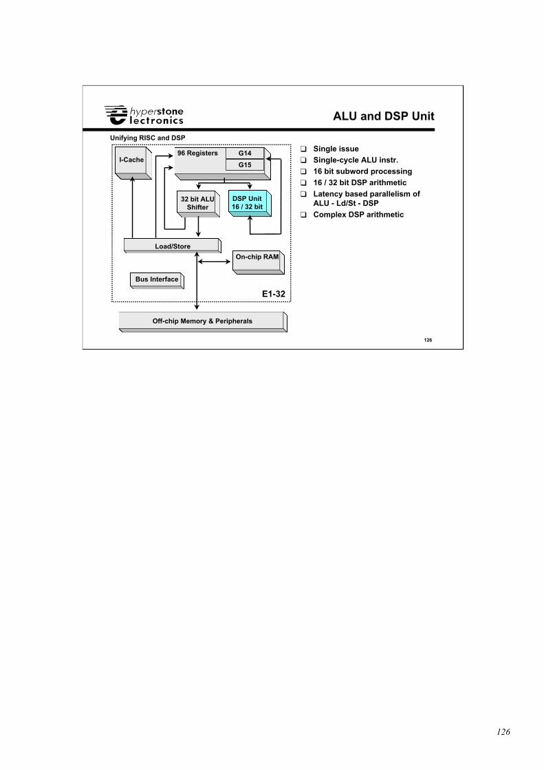
126
126
Unifying RISC and DSP
ALU and DSP Unit
32 bit ALUShifter
Load/Store
96 Registers
DSP Unit16 / 32 bit
On-chip RAM
I-Cache
Bus Interface
Off-chip Memory & Peripherals
E1-32
❑ Single issue❑ Single-cycle ALU instr.
❑ 16 bit subword processing
❑ 16 / 32 bit DSP arithmetic
❑ Latency based parallelism ofALU - Ld/St - DSP
❑ Complex DSP arithmetic
G14
G15
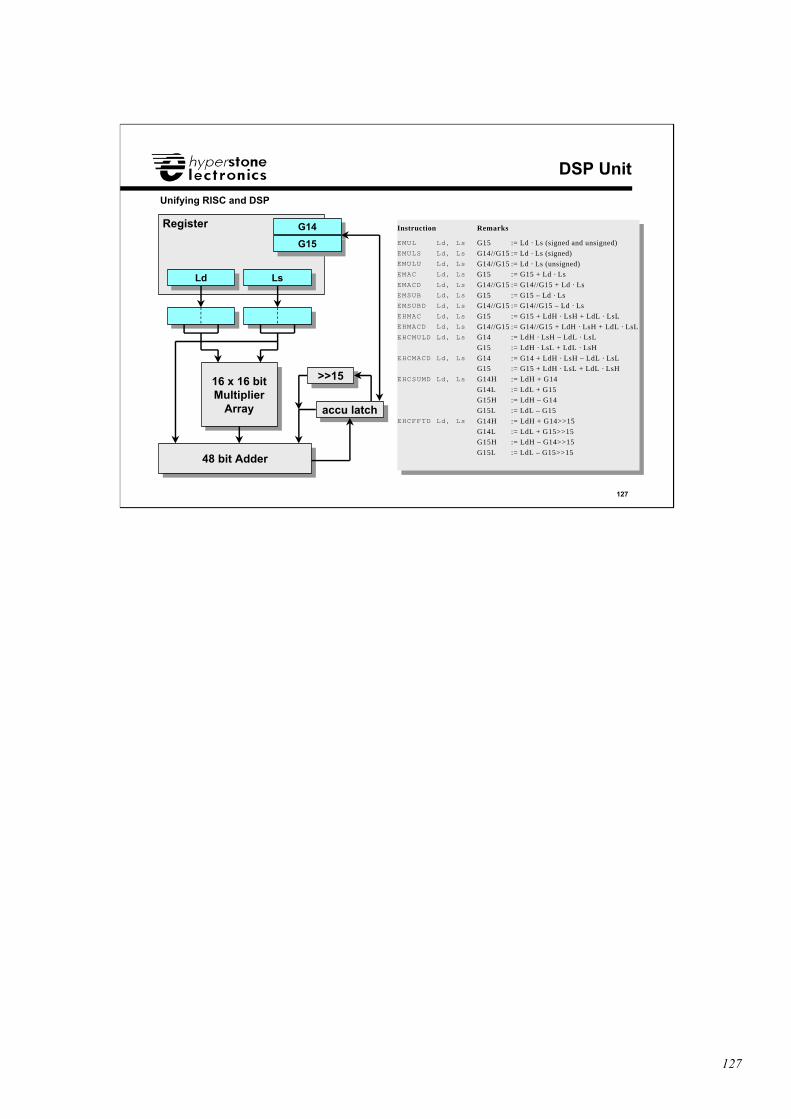
127
127
Unifying RISC and DSP
DSP Unit
LdLd LsLs
RegisterG14G14
G15G15
16 x 16 bitMultiplier
Array
16 x 16 bitMultiplier
Array
48 bit Adder48 bit Adder
accu latchaccu latch
>>15>>15
Instruction Remarks
EMUL Ld, Ls G15 := Ld · Ls (signed and unsigned)EMULS Ld, Ls G14//G15 := Ld · Ls (signed)EMULU Ld, Ls G14//G15 := Ld · Ls (unsigned)EMAC Ld, Ls G15 := G15 + Ld · LsEMACD Ld, Ls G14//G15 := G14//G15 + Ld · LsEMSUB Ld, Ls G15 := G15 – Ld · LsEMSUBD Ld, Ls G14//G15 := G14//G15 – Ld · LsEHMAC Ld, Ls G15 := G15 + LdH · LsH + LdL · LsLEHMACD Ld, Ls G14//G15 := G14//G15 + LdH · LsH + LdL · LsLEHCMULD Ld, Ls G14 := LdH · LsH – LdL · LsL
G15 := LdH · LsL + LdL · LsHEHCMACD Ld, Ls G14 := G14 + LdH · LsH – LdL · LsL
G15 := G15 + LdH · LsL + LdL · LsHEHCSUMD Ld, Ls G14H := LdH + G14
G14L := LdL + G15G15H := LdH – G14
G15L := LdL – G15EHCFFTD Ld, Ls G14H := LdH + G14>>15
G14L := LdL + G15>>15G15H := LdH – G14>>15
G15L := LdL – G15>>15
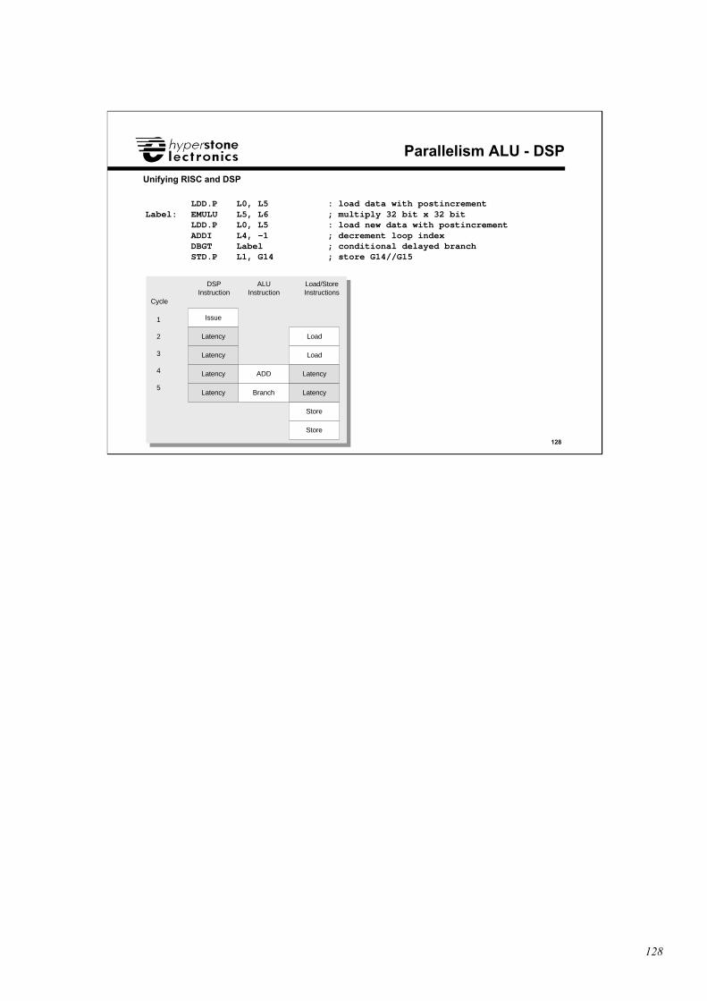
128
128
Unifying RISC and DSP
Parallelism ALU - DSP
LDD.P L0, L5 : load data with postincrementLabel: EMULU L5, L6 ; multiply 32 bit x 32 bit
LDD.P L0, L5 : load new data with postincrementADDI L4, -1 ; decrement loop indexDBGT Label ; conditional delayed branchSTD.P L1, G14 ; store G14//G15
Issue
Latency
Latency
Latency
Cycle
1
2
3
4
5
DSP Instruction
Load
ALU Instruction
Load/Store Instructions
ADD
BranchLatency
Store
Latency
Latency
Store
Load
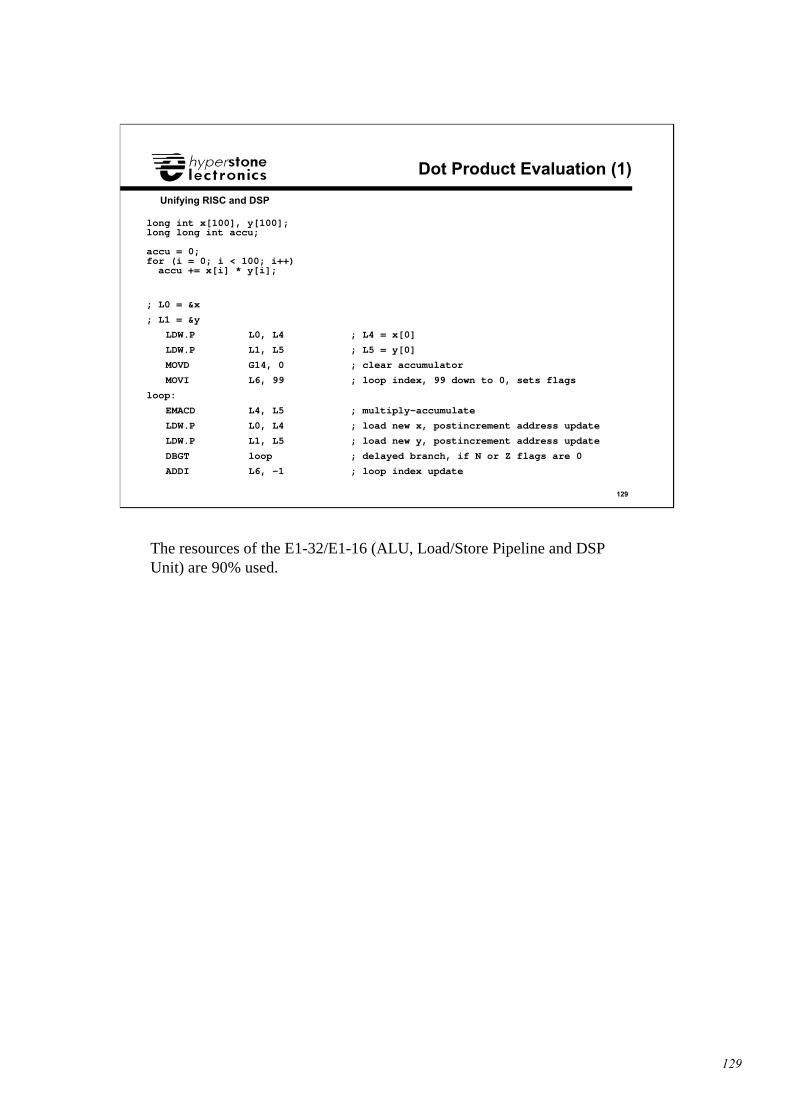
129
129
Unifying RISC and DSP
Dot Product Evaluation (1)
long int x[100], y[100];long long int accu;
accu = 0;for (i = 0; i < 100; i++) accu += x[i] * y[i];
; L0 = &x
; L1 = &y
LDW.P L0, L4 ; L4 = x[0]
LDW.P L1, L5 ; L5 = y[0]
MOVD G14, 0 ; clear accumulator
MOVI L6, 99 ; loop index, 99 down to 0, sets flags
loop:
EMACD L4, L5 ; multiply-accumulate
LDW.P L0, L4 ; load new x, postincrement address update
LDW.P L1, L5 ; load new y, postincrement address update
DBGT loop ; delayed branch, if N or Z flags are 0
ADDI L6, -1 ; loop index update
The resources of the E1-32/E1-16 (ALU, Load/Store Pipeline and DSPUnit) are 90% used.
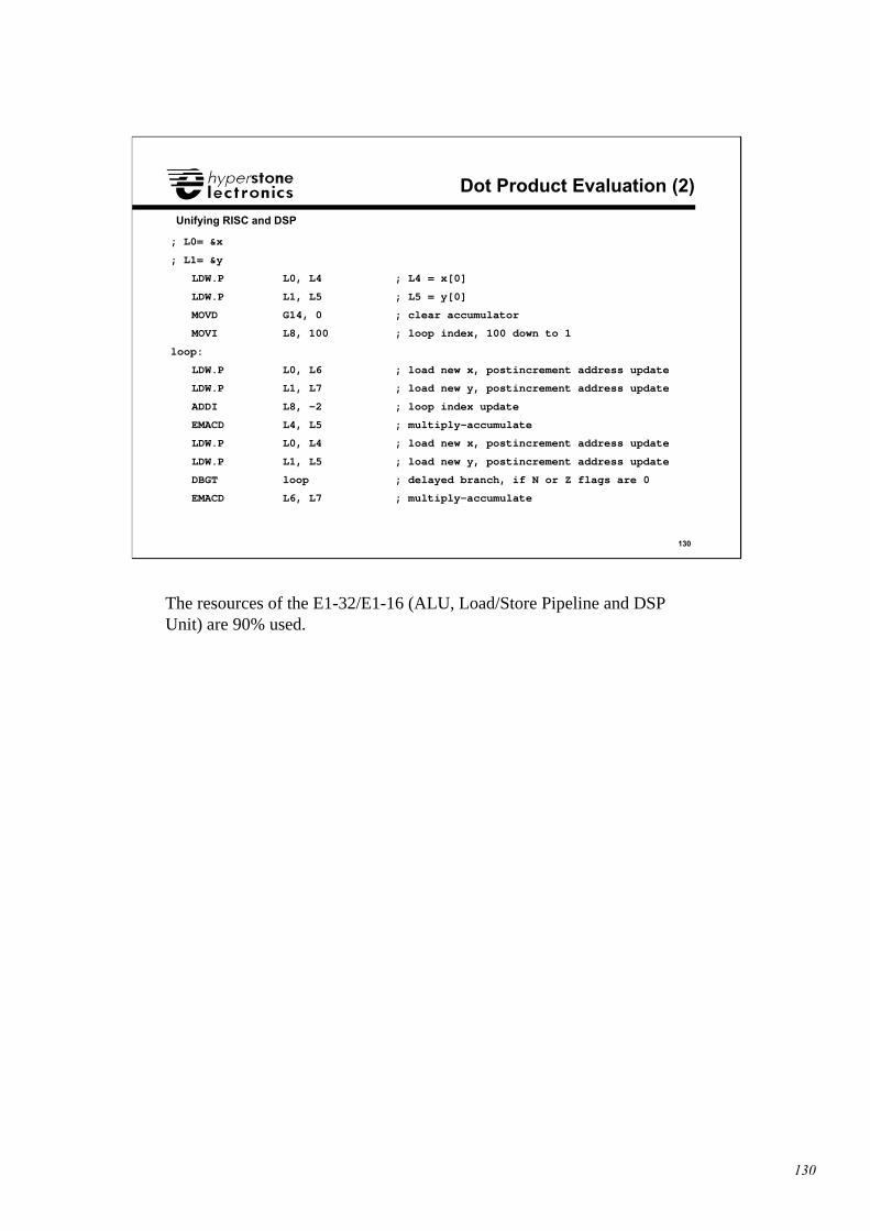
130
130
Unifying RISC and DSP
Dot Product Evaluation (2)
; L0= &x
; L1= &y
LDW.P L0, L4 ; L4 = x[0]
LDW.P L1, L5 ; L5 = y[0]
MOVD G14, 0 ; clear accumulator
MOVI L8, 100 ; loop index, 100 down to 1
loop:
LDW.P L0, L6 ; load new x, postincrement address update
LDW.P L1, L7 ; load new y, postincrement address update
ADDI L8, -2 ; loop index update
EMACD L4, L5 ; multiply-accumulate
LDW.P L0, L4 ; load new x, postincrement address update
LDW.P L1, L5 ; load new y, postincrement address update
DBGT loop ; delayed branch, if N or Z flags are 0
EMACD L6, L7 ; multiply-accumulate
The resources of the E1-32/E1-16 (ALU, Load/Store Pipeline and DSPUnit) are 90% used.


![[3] E. D. [6] D. - Springer978-1-4757-2649-7/1.pdf · [58] Hyperstone Electronics, Hyperstone El 32-Bit-Microprocessor User's Manual. 1990. [59] J. Stankovic and K. Ramamritham, Tutorial](https://img.pdfslide.us/doc/110x75/5aaee7c07f8b9a07498caf45/3-e-d-6-d-springer-978-1-4757-2649-71pdf58-hyperstone-electronics.jpg)