Embed Size (px)
Citation preview
ANALYTICAL SERVICES & MATERIALS, INC.
107 Research Drive, Hampton, VA 23666 tel. (757) 865-7093 fax (757) 865-7309
SBIR Phase II Final ReportNAS1- 00006 April 2002
Unified Process Management System for Computational Fluid Dynamics (UPMS)
by Khaled S. Abdol-Hamid, Steven J. Massey, and Shane Caldwell
ANALYTICAL SERVICES & MATERIALS, INC.
107 Research Drive, Hampton, VA 23666 tel. (757) 865-7093 fax (757) 865-7309
SBIR Phase II Final Report, NAS1-00006, April 2002
Unified Process Management System for Computational Fluid Dynamics (UPMS)
by Khaled S. Abdol-Hamid, Steven J. Massey, and Shane Caldwell
1
COPYRIGHT 2002 BY ANALYTICAL SERVICES & MATERIALS, INC. ALL RIGHTS RESERVED. REPRODUCTION OR TRANSLATION OF ANY PART OF THIS WORK BEYOND THAT PERMITTED BY SECTION 107 OR 108 OF THE 1976 UNITED STATES COPYRIGHT ACT WITHOUT THE PERMISSION OF THE COPYRIGHT OWNER IS UNLAWFUL. REQUESTS FOR PERMISSION OR FURTHER INFORMATION SHOULD BE ADDRESSED TO DR. KHALED ABDOL-HAMID, ANALYTICAL SERVICES & MATERIALS, INC., 107 RESEARCH DRIVE, HAMPTON, VA 23666.
SBIR RIGHTS NOTICE (MAR 1994): These SBIR data are furnished with SBIR rights under Contract No. NAS1-00006. For a period of 4 years after acceptance of all items to be delivered under this contract, the Government agrees to use these data for Government purposes only, and they shall not be disclosed outside the Government (including disclosure for procurement purposes) during such period without permission of the Contractor, except that, subject to the foregoing use and disclosure prohibitions, such data may be disclosed for use by support Contractors. After the aforesaid 4-year period the Government has a royalty-free license to use, and to authorize others to use on its behalf, these data for Government purposes, but is relieved of all disclosure prohibitions and assumes no liability for unauthorized use of these data by third parties. This Notice shall be affixed to any reproductions of these data, in whole or in part.
TABLE OF CONTENTS
1.0 ABSTRACT ............................................................................................................................................ 3
2.0 BACKGROUND..................................................................................................................................... 3
3.0 TECHNICAL OBJECTIVES................................................................................................................ 5
4.0 PHASE II APPLICATIONS AND KEY INNOVATIONS................................................................. 6
5.0 WORK PERFORMED AND RESULTS.............................................................................................. 7
5.1 STRUCTURAL DEVELOPMENT................................................................................................................ 9 5.2 PAB3D ENHANCEMENTS...................................................................................................................... 9 5.3 UNIFIED CFD INTERFACE ................................................................................................................... 13
5.3.1 Flexible Input/Output (I/O).......................................................................................................... 13 5.3.2 Unified CFD Solver Setup with Expert Help ............................................................................... 15 5.3.3 Online Help ................................................................................................................................. 17 5.3.4 UPMS Examples .......................................................................................................................... 17
5.4 MESH EDITOR AND ADAPTATION (GRIDIRON) .................................................................................... 18
6.0 ASSESSMENT OF TECHNICAL MERIT........................................................................................ 23
7.0 PHASE III POTENTIAL WORK....................................................................................................... 23
8.0 REFERENCES ..................................................................................................................................... 26
2
1.0 Abstract The Unified Process Management System (UPMS) is a valuable Computational
Fluid Dynamics (CFD) analysis tool that utilizes NASA’s CFD codes: PAB3D, CFL3D and TLNS3D. Each of these CFD codes has a specific format for input files. The choice of a particular CFD code depends upon its reliability for a particular class of flow, its ease of use and the availability of technical support. However, it is difficult to find a CFD code that combines all of these requirements. Even simple modifications in problem definition would require extensive alterations to these formats. Often, users must be trained by CFD code suppliers to enable them to model the problem correctly, and to use the available options in the code efficiently.
Familiarization with more than one code becomes difficult when seeking CFD solutions for a particular configuration. The UPMS alleviates these difficulties with the use of an expert Graphical User Interface (GUI) system. The system also includes interactive adaptive grid capabilities and grid modification processes. The significance of this work is its flexibility in allowing these CFD structured grid codes to be coupled with the UPMS without any modifications whatsoever to the CFD solvers. It automatically generates documentation of code-independent project/ problem setup in engineering terms. The UPMS was written in the object-oriented and highly portable JAVA programming language.
2.0 Background With the recent emphasis by NASA on cheaper access to space, several of the
current and planned X-airplane research programs are studying hypersonic, air-breathing, and single-stage-to-orbit vehicles. These vehicles require efficient methods for analyzing high-speed flows. References [1-8] describe some of the CFD codes which are used to analyze high-speed flows. The hypersonic flows are extremely complex. However, an advanced CFD system will prove to be the most suitable to simulate these complex high-speed flight conditions.
The advent of high-speed computers with enhanced utilities has rendered simulation and visualization of complex fluid dynamic phenomena possible. In addition, the development and improvement of distributed computer libraries (MPICH and LAM) will allow the expansion of computer power to continue at a fast pace, thereby enabling the design engineer to obtain flow solutions for more complex problems. Advanced turbulence models, including multi-equation models, can closely simulate the physics for turbulent flow. Results obtained through such analysis compare well with actual results. Such efforts have heightened the faith in numerical simulation and have led to the numerical simulation codes becoming more widely used. So far, the choice of a particular CFD code depends upon its reliability, its ease of use, and technical support. However, it is difficult to find a CFD code that meets several requirements.
Figure 1 shows two of the essential components for a complete CFD system. Problem setup is considered to be one of the difficulties in working with CFD codes. Simple modifications in problem definition often require extensive alterations to these formats. Generally, users are required to be trained by the code suppliers to enable them to model the problem correctly and to use the various options available in the code
3
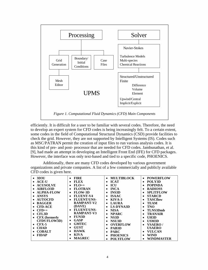
Processing Solver
GridGeneration
Boundary/Initial
Conditions
CaseFiles
MeshEditor
Navier-Stokes
Turbulence ModelsMulti-speciesChemical Reactions
Structured/Unstructured Finite Difference Volume Element
Upwind/CentralImplicit/Explicit
UPMS
Figure 1. Computational Fluid Dynamics (CFD) Main Components
efficiently. It is difficult for a user to be familiar with several codes. Therefore, the need to develop an expert system for CFD codes is being increasingly felt. To a certain extent, some codes in the field of Computational Structural Dynamics (CSD) provide facilities to check the grid. However, they are not supported by Intelligent Systems (IS). Codes such as MSC/PATRAN permit the creation of input files to run various analysis codes. It is this kind of pre- and post- processor that are needed for CFD codes. Jambunathan, et al. [9], had made an attempt in developing an Intelligent Front End (IFE) for CFD packages. However, the interface was only text-based and tied to a specific code, PHOENICS.
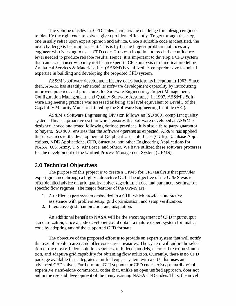
Additionally, there are many CFD codes developed by various government organizations and private companies. A list of a few commercially and publicly available CFD codes is given here.
• 3D3U • ACE-U • ACUSOLVE • AIRFLO3D • ALPHA-FLOW • ANSYS • AUTOCFD • BAGGER • CFD-ACE • CFD++ • CFL3D • CFX (formerly
CFDS FLOW3D) • CFX-5 • CHAD • COBALT • FIDAP
• FIRE • FLEX • FLO++ • FLOTRAN • FLOW-3D • FLUENT-V4 • FLUENT/UNS-
RAMPANT-V2 (DAVE)
• FLUENT/UNS-RAMPANT-V3
• FUN3D • GASP • GMTEC • GUST • HAWK • KIVA • MAGREC
• MULTIBLOCK • ICAT • ICU • INCA • INS3D • ISAAC • KIVA-3 • LAURA • LS-DYNA3D • NISA • NPARC • NS3D • NSU3D • OVERFLOW • PAB3D • PARC • PHOENICS • POLYFLOW
• POWERFLOW • POLY3D • POPINDA • RADIOSS • SPLITFLOW • STARCD • TASCflow • TEAM • TNO • TLNS3Dmb • TRANAIR • UH3D • USM3D • VSAERO /
USAERO • VULCAN • WIND • WINDMASTER
4
The volume of relevant CFD codes increases the challenge for a design engineer to identify the right code to solve a given problem efficiently. To get through this step, one usually relies upon expert opinion and advice. Once a suitable code is identified, the next challenge is learning to use it. This is by far the biggest problem that faces any engineer who is trying to use a CFD code. It takes a long time to reach the confidence level needed to produce reliable results. Hence, it is important to develop a CFD system that can assist a user who may not be an expert in CFD analysis or numerical modeling. Analytical Services & Materials, Inc. (AS&M) has utilized its comprehensive technical expertise in building and developing the proposed CFD system.
AS&M’s software development history dates back to its inception in 1983. Since then, AS&M has steadily enhanced its software development capability by introducing improved practices and procedures for Software Engineering, Project Management, Configuration Management, and Quality Software Assurance. In 1997, AS&M’s Soft-ware Engineering practice was assessed as being at a level equivalent to Level 3 of the Capability Maturity Model instituted by the Software Engineering Institute (SEI).
AS&M’s Software Engineering Division follows an ISO 9001 compliant quality system. This is a proactive system which ensures that software developed at AS&M is designed, coded and tested following defined practices. It is also a third party guarantor to buyers. ISO 9001 ensures that the software operates as expected. AS&M has applied these practices to the development of Graphical User Interfaces (GUIs), Database Appli-cations, NDE Applications, CFD, Structural and other Engineering Applications for NASA, U.S. Army, U.S. Air Force, and others. We have utilized these software processes for the development of the Unified Process Management System (UPMS).
3.0 Technical Objectives The purpose of this project is to create a UPMS for CFD analysis that provides
expert guidance through a highly interactive GUI. The objective of the UPMS was to offer detailed advice on grid quality, solver algorithm choice and parameter settings for specific flow regimes. The major features of the UPMS are:
1. A unified expert system embedded in a GUI, which provides interactive assistance with problem setup, grid optimization, and setup verification.
2. Interactive grid manipulation and adaptation.
An additional benefit to NASA will be the encouragement of CFD input/output standardization, since a code developer could obtain a mature expert system for his/her code by adopting any of the supported CFD formats.
The objective of the proposed effort is to provide an expert system that will notify the user of problem areas and offer corrective measures. The system will aid in the selec-tion of the most efficient solution schemes, turbulence models, chemical reaction simula-tion, and adaptive grid capability for obtaining flow solution. Currently, there is no CFD package available that integrates a unified expert system with a GUI that uses an advanced CFD solver. Furthermore, GUI support for CFD codes exists primarily within expensive stand-alone commercial codes that, unlike an open unified approach, does not aid in the use and development of the many existing NASA CFD codes. Thus, the novel
5
approach of integrating an expert system, grid modification tools, and the preparation of input files to a group of advanced Navier-Stokes codes will greatly benefit not only NASA, but the industry and the academia as well. The capabilities of the UPMS include:
1. An expert system which guides the user through all the aspects of problem setup. 2. Online help to give the user information and recommendations for using a
particular CFD code. 3. Capability to work with other CFD codes and more utilities to enhance the pre-
and post-processing of CFD codes. 4. Adaptive grid capability to match the computational grid to the changes in the
flow condition for a wide range of Mach numbers and flow physics.
The above capabilities of UPMS will provide a powerful CFD pre-processing tool that would significantly save user time in terms of problem setup, grid modification, and repeated processing with minor changes in problem set-up. The PAB3D code is available from AS&M. CFL3D and TLNS3D can be requested from NASA Langley. During this Phase II effort, we incorporated the following new items in the PAB3D code:
1. A simple chemical reaction model that couples the transport equations with a generalized chemistry model.
2. Advanced turbulence models for accurate prediction of flow physics.
4.0 Phase II Applications and Key Innovations The UPMS was constructed in its complete form of GUI using JAVA,
FORTRAN, and C computer languages. The UPMS consists of two packages. The first package is a unified preprocessing approach for PAB3D-CFL3D-TLNS3D CFD codes. The second package is grid manipulation, adaptation and a quality assessment tool. The significance of this work is its flexibility in allowing NASA CFD grid structured codes to be coupled with the UPMS without any modifications whatsoever to the CFD solvers. In addition, the UPMS provides expert guidance to users.
By making CFD tools more robust while also improving the accuracy and provid-ing physical insight to the user, the UPMS will increase the commercial viability of CFD as a useful design tool. Major industries that use CFD codes include aerospace, auto-motive, biomedical, electronics packaging, manufacturing, and civil engineering. Compu-tational efficiency is the key in producing quality CFD results quickly enough to be economically viable to commercial design engineers. Inexperienced users may pose grossly inefficient problems due to poor grid design and/or algorithm setup. The commercial value of an expert UPMS is that its detailed feedback and automatic grid modification capabilities allow novice users to quickly gain experience in properly posed CFD analysis.
CFL3D and TLNS3D are some of the CFD codes that were developed under NASA funding. Most of the users of a particular CFD code also use other CFD codes for comparison. However, learning to use a new code may be time and cost prohibitive even
6
though the new code may be appropriate for a particular problem. The major key innovations for the UPMS are:
- Expert system and object-oriented approach. - Dialog box GUI for problem setup. - Platform independent Java byte-code. - Problem setup with limited information. - Quality control and consistency. - Common background master process. - Simple project file available for the next project engineer. - Short process time and small cost. - Use of various CFD codes. - Grid adaptation and manipulation. - Automatic documentation of code-independent project/problem setup in
engineering terms.
Experts will also benefit by the ability to quickly switch between different CFD codes to obtain the best fit for the flow regime under consideration, thus minimizing design cost. NASA software developers will benefit from the commercial quality front ends offered by the UPMS to their research codes. NASA engineers will be able to use NASA CFD codes more effectively to fulfill NASA’s mission. The following are a few of the benefits offered by the UPMS for NASA and aerospace industries:
- Allows engineers to use several NASA CFD codes. - Speeds up the technology transfer of NASA CFD codes to the public as they
become easier to use. - Reduces the technical support for each code as users can utilize the online
help provided by the expert system. - Provides a universal case file which can be used to generate input files for any
particular CFD code. - Keeps information that can be stored for later use or sent to another
organization, or can be grouped to simulate the same problem using another CFD code.
- Builds a library of standard test cases. The input library will provide the user with direct access to a large and growing database of problem setup and input files.
- Offers demonstration or teaching examples as a starting point for the novice.
5.0 Work Performed and Results The UPMS was constructed in the form of a GUI with modules for grid
manipulation, grid quality assessment, block interface patching, and solver setup for PAB3D/CFL3D/TLNS3D CFD codes. The system requirements define the features, functions, operational requirements, and constraints of the UPMS CFD system (Table 1).
7
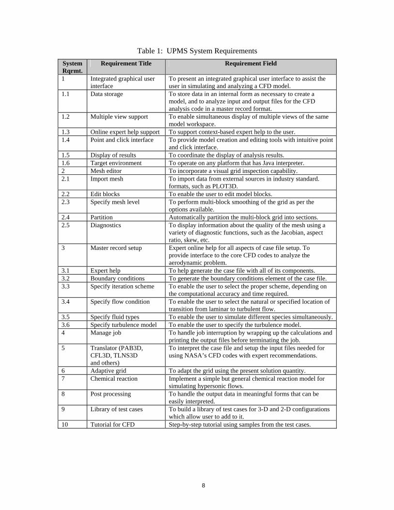
Table 1: UPMS System Requirements System Rqrmt.
Requirement Title Requirement Field
1 Integrated graphical user interface
To present an integrated graphical user interface to assist the user in simulating and analyzing a CFD model.
1.1 Data storage To store data in an internal form as necessary to create a model, and to analyze input and output files for the CFD analysis code in a master record format.
1.2 Multiple view support To enable simultaneous display of multiple views of the same model workspace.
1.3 Online expert help support To support context-based expert help to the user. 1.4 Point and click interface To provide model creation and editing tools with intuitive point
and click interface. 1.5 Display of results To coordinate the display of analysis results. 1.6 Target environment To operate on any platform that has Java interpreter. 2 Mesh editor To incorporate a visual grid inspection capability. 2.1 Import mesh To import data from external sources in industry standard.
formats, such as PLOT3D. 2.2 Edit blocks To enable the user to edit model blocks. 2.3 Specify mesh level To perform multi-block smoothing of the grid as per the
options available. 2.4 Partition Automatically partition the multi-block grid into sections. 2.5 Diagnostics To display information about the quality of the mesh using a
variety of diagnostic functions, such as the Jacobian, aspect ratio, skew, etc.
3 Master record setup Expert online help for all aspects of case file setup. To provide interface to the core CFD codes to analyze the aerodynamic problem.
3.1 Expert help To help generate the case file with all of its components. 3.2 Boundary conditions To generate the boundary conditions element of the case file. 3.3 Specify iteration scheme To enable the user to select the proper scheme, depending on
the computational accuracy and time required. 3.4 Specify flow condition To enable the user to select the natural or specified location of
transition from laminar to turbulent flow. 3.5 Specify fluid types To enable the user to simulate different species simultaneously. 3.6 Specify turbulence model To enable the user to specify the turbulence model. 4 Manage job To handle job interruption by wrapping up the calculations and
printing the output files before terminating the job. 5 Translator (PAB3D,
CFL3D, TLNS3D and others)
To interpret the case file and setup the input files needed for using NASA’s CFD codes with expert recommendations.
6 Adaptive grid To adapt the grid using the present solution quantity. 7 Chemical reaction Implement a simple but general chemical reaction model for
simulating hypersonic flows. 8 Post processing To handle the output data in meaningful forms that can be
easily interpreted. 9 Library of test cases To build a library of test cases for 3-D and 2-D configurations
which allow user to add to it. 10 Tutorial for CFD Step-by-step tutorial using samples from the test cases.
8
5.1 Structural Development The design features of the UPMS concentrates on creating an easily expandable and maintainable program. We anticipate to add many new features in the future. Some of the interfaces may be such that their form, function, or interfaces cannot be determined in advance. Consequently, we have emphasized modular interfaces and flexible archi-tecture. The reliability and consistency of the data display from the case file, and the compatibility of the output case file, were considered as the measure of effectiveness of the UPMS. Table 2 presents acceptance criteria for UPMS. These requirements are taken from Table 1.
Table 2. Acceptance Criteria for UPMS
System Rqmt. No.
Requirement Title Requirements Description
1.1 Data storage To store data in an internal format necessary to create the model, and to analyze input and output files for the CFD analysis code in a master record format.
3 Master record setup Expert online help for all aspects of case file setup. To provide interface to the core CFD codes to analyze the aerodynamic problem.
5 “Masked” master record (PAB3D, CFL3D, TLNS3D and others)
To interpret the case file and setup the input files needed for using NASA CFD codes with expert recommendation for the respective flow condition.
The UPMS maintains a general case information database that is capable of being
translated to any CFD solver with the code-specific parameters automatically filled with appropriate default values. The utility of this dual language/interface approach makes the UPMS totally independent of the CFD programs it drives. This affords the CFD users and developers maximum flexibility because they can utilize the UPMS to generate the initial input files and then run the codes in batch mode. Also, CFD developers need not relin-quish control of their codes or even collaborate in any way with the UPMS developers, since no source code modifications are necessary. A well-known and successful example of this approach to software development is the PostScript interpreter Ghostscript and companion front ends Ghostview (Unix) and GSView (Windows). In the following sections, we will describe the work completed during the course of the SBIR Phase II.
5.2 PAB3D Enhancements In recognition of the importance of the continued enhancement of the PAB3D
solver for use in the U.S. aerospace industry and NASA’s hypersonic projects, the NASA Langley Research Center has advocated the long-term development of the code. PAB3D solves the three-dimensional Reynolds-averaged Navier-Stokes equations with a finite-volume formulation on structured multi-block grids. NASA Langley and AS&M have jointly executed a Memorandum of Agreement (MOA) to foster commercialization of the PAB3D code. Parts of the enhancements for the PAB3D were completed during this SBIR Phase II work. PAB3D was originally developed under several NASA contracts. It received recognition in the aerospace industry for its accuracy, speed, low memory requirement, and multiple choices of advanced turbulence models. The details of the
9
work completed in turbulence models, simple chemical reaction, and distributed computer capacities is described below.
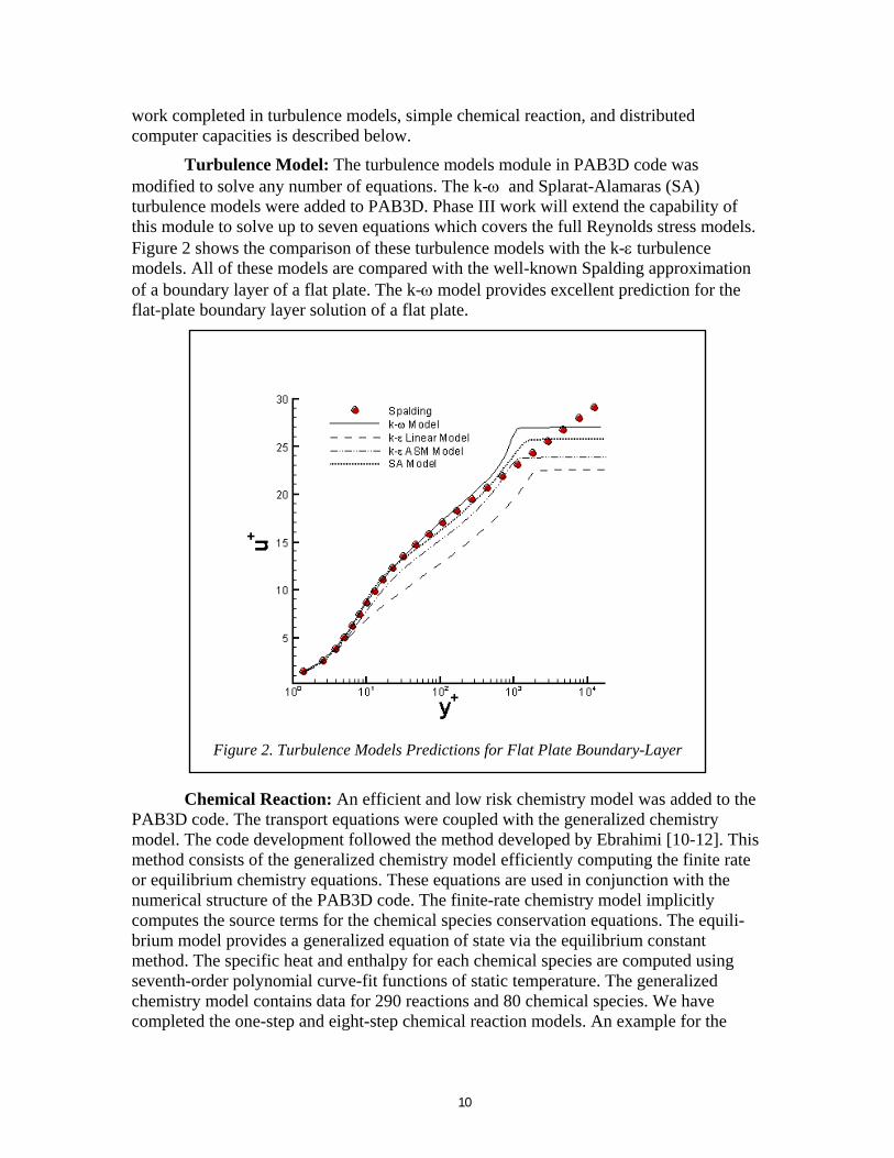
Turbulence Model: The turbulence models module in PAB3D code was modified to solve any number of equations. The k-ω and Splarat-Alamaras (SA) turbulence models were added to PAB3D. Phase III work will extend the capability of this module to solve up to seven equations which covers the full Reynolds stress models. Figure 2 shows the comparison of these turbulence models with the k-ε turbulence models. All of these models are compared with the well-known Spalding approximation of a boundary layer of a flat plate. The k-ω model provides excellent prediction for the flat-plate boundary layer solution of a flat plate.
Figure 2. Turbulence Models Predictions for Flat Plate Boundary-Layer
Chemical Reaction: An efficient and low risk chemistry model was added to the PAB3D code. The transport equations were coupled with the generalized chemistry model. The code development followed the method developed by Ebrahimi [10-12]. This method consists of the generalized chemistry model efficiently computing the finite rate or equilibrium chemistry equations. These equations are used in conjunction with the numerical structure of the PAB3D code. The finite-rate chemistry model implicitly computes the source terms for the chemical species conservation equations. The equili-brium model provides a generalized equation of state via the equilibrium constant method. The specific heat and enthalpy for each chemical species are computed using seventh-order polynomial curve-fit functions of static temperature. The generalized chemistry model contains data for 290 reactions and 80 chemical species. We have completed the one-step and eight-step chemical reaction models. An example for the
10
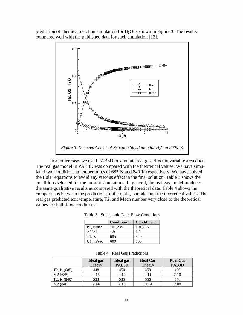
prediction of chemical reaction simulation for H2O is shown in Figure 3. The results compared well with the published data for such simulation [12].
In another case, we used PAB3D to simulate real gas effect in variable area duct. The real gas model in PAB3D was compared with the theoretical values. We have simu-lated two conditions at temperatures of 685oK and 840oK respectively. We have solved the Euler equations to avoid any viscous effect in the final solution. Table 3 shows the conditions selected for the present simulations. In general, the real gas model produces the same qualitative results as compared with the theoretical data. Table 4 shows the comparisons between the predictions of the real gas model and the theoretical values. The real gas predicted exit temperature, T2, and Mach number very close to the theoretical values for both flow conditions.
Table 3. Supersonic Duct Flow Conditions
Condition 1 Condition 2 P1, N/m2 101,235 101,235 A2/A1 1.9 1.9 T1, K 685 840 U1, m/sec 600 600
IdeT
T2, K (685) M2 (685) T2, K (840) M2 (840)
Figure 3. One-step Chemical Reaction Simulation for H2O at 2000 oK
Table 4. Real Gas Predictions
al gas heory
Ideal gas PAB3D
Real Gas Theory
Real Gas PAB3D
448 450 458 460 2.15 2.14 2.11 2.10 533 535 556 558 2.14 2.13 2.074 2.08
11
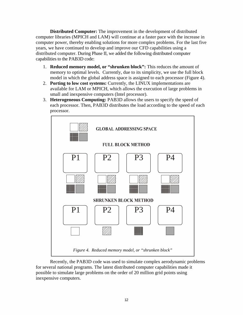
Distributed Computer: The improvement in the development of distributed computer libraries (MPICH and LAM) will continue at a faster pace with the increase in computer power, thereby enabling solutions for more complex problems. For the last five years, we have continued to develop and improve our CFD capabilities using a distributed computer. During Phase II, we added the following distributed computer capabilities to the PAB3D code:
1. Reduced memory model, or “shrunken block”: This reduces the amount of memory to optimal levels. Currently, due to its simplicity, we use the full block model in which the global address space is assigned to each processor (Figure 4).
2. Porting to low cost systems: Currently, the LINUX implementations are available for LAM or MPICH, which allows the execution of large problems in small and inexpensive computers (Intel processor).
3. Heterogeneous Computing: PAB3D allows the users to specify the speed of each processor. Then, PAB3D distributes the load according to the speed of each processor.
Recently, the PAB3D code was used to simulate complex aerodynamic problems for several national programs. The latest distributed computer capabilities made it possible to simulate large problems on the order of 20 million grid points using inexpensive computers.
P1
P1
P2
P2
P3
P3
P4
P4
Figure 4. Reduced memory model, or “shrunken block”
12
5.3 Unified CFD Interface The system interface is composed of the workspace, screens, pull-down menus,
tool bars, context-sensitive help and online user manual. It will be possible to save the workspace (the state and data of the model) at any time to a named file, and to retrieve a previously saved state and contents at any time to resume work. The GUI’s screens use clear, natural language descriptions, labels and instructions to communicate with the user. The dialog boxes also provide the available choices to the user in combo-boxes or list boxes for the user to select. Data is validated during data entry. The expert system operates in both the UNIX/X-Window environment and Microsoft Windows environ-ment, employing the industry standard interfaces of the Java computer language. The choice of the Java programming language provides a highly portable object-oriented code. UPMS supports commonly available graphics systems such as MS Direct-X, Unix X and OpenGL.
The design philosophy is to have the system direct the automatic creation of general elements of the input files and then have the user supply the minimum amount of information to complete the physical and numerical specification of the simulation. The UPMS interface for PAB3D, CFL3D and TLNS3D contains the following essential components:
– Flexible GUI I/O and object oriented procedure.
– Unified CFD solver setup for PAB3D, CFL3D and TLNS3D.
– Fast problem setup with minimum knowledge of the problem.
– Expert help and verification of the setup integrity.
– Online Help and up-to-date documentation of selected CFD codes with step-by-step online tutorials for problem setup.
5.3.1 Flexible Input/Output (I/O) Starting a new project can proceed through a very fast and accurate procedure to setup geometry information with limited knowledge of the problem. This automated procedure, known as AutoG3d, is a very fast process as it takes less than one minute to produce a draft boundary conditions file with over 90% accuracy, for 5 million grid points using PIII/600Mhz CPU. The information generated by AutoG3d has a 90% accuracy rate in producing boundary condition data. We are investigating other methods which can improve the accuracy to a perfect automatic patching processor. In Phase III, we will add more import options to allow users to use formats such as grid generation or geometry files. The UPMS I/O is flexible and it allows three-input and two-output formats (Figure 5a). The three-input formats are:
1. Start old project.
- Import any of the three CFD codes: PAB3D, CFL3D or TLNS3D. Users will need the CFD code control files and grid file.
- Load a project in the UPMS format. Input to this form through the project name and grid file.
13

2. Start a new project with the grid file and the essential boundary conditions (wall, symmetry, inflow and outflow). In this mode, the UPMS will utilize the AutoG3d software developed by Dr. Paul Pao at NASA Langley to automatically generate boundary condition with minimum knowledge of the geometry.
Figure 5a: Flexible I/O for Unified Process Management System
The two-output formats are:
- UPMS format. Users do not need to fix all the issues or complete the project in order to save in this format.
- Full set of input files to drive any one of the three CFD codes: PAB3D, CFL3D or TLNS3D. However, verification of the information will be checked, and will allow the users to fix any issues before exporting.
UPMS uses a common background master process as shown in Figure 5b. The common data is automatically stored in this record even as the user works in any of the CFD codes. Each of the CFD code data is a subset of the master record. This will facili-tate the flexibility of translating to any CFD code format without the knowledge of the original source of information. It is always a one-way translation from UPMS to the required CFD code output.
14
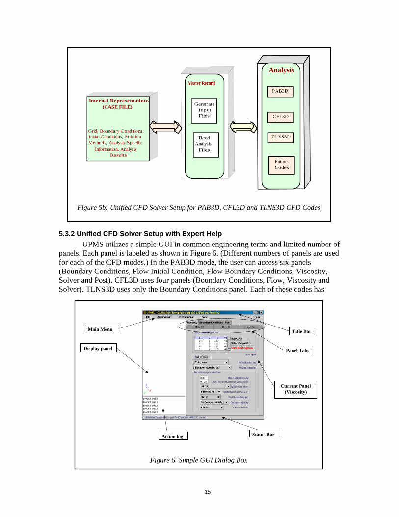
5.3.2 Unified CFD Solver Setup with Expert Help UPMS utilizes a simple GUI in common engineering terms and limited number of panels. Each panel is labeled as shown in Figure 6. (Different numbers of panels are used for each of the CFD modes.) In the PAB3D mode, the user can access six panels (Boundary Conditions, Flow Initial Condition, Flow Boundary Conditions, Viscosity, Solver and Post). CFL3D uses four panels (Boundary Conditions, Flow, Viscosity and Solver). TLNS3D uses only the Boundary Conditions panel. Each of these codes has
Internal Representations(CASE FILE)
Grid, Boundary C onditions,Initial Conditions, SolutionMethods, Analysis Specific
Information, AnalysisResults
GenerateInputFiles
ReadAnalysis
Files
Analysis
Master RecordPAB3D
FutureCodes
TLNS3D
CFL3D
Figure 5b: Unified CFD Solver Setup for PAB3D, CFL3D and TLNS3D CFD Codes
Title Bar
Panel Tabs
Current Panel(Viscosity)
Status BarAction log
Display panel
Main Menu
Figure 6. Simple GUI Dialog Box
15
different levels of complexity. Also, not all of the capabilities of these CFD codes are included in the UPMS, based on the communications we have had with CFD code developers. It is beyond the scope of this report to explain the details of each panel and its elations to a specific CFD code. r
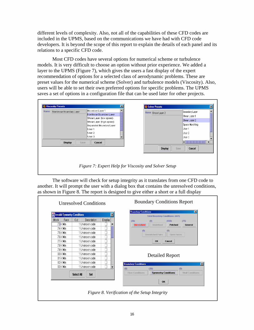
Most CFD codes have several options for numerical scheme or turbulence models. It is very difficult to choose an option without prior experience. We added a layer to the UPMS (Figure 7), which gives the users a fast display of the expert recommendation of options for a selected class of aerodynamic problems. These are preset values for the numerical scheme (Solver) and turbulence models (Viscosity). Also, users will be able to set their own preferred options for specific problems. The UPMS saves a set of options in a configuration file that can be used later for other projects.
Figure 7: Expert Help for Viscosity and Solver Setup
The software will check for setup integrity as it translates from one CFD code to another. It will prompt the user with a dialog box that contains the unresolved conditions, as shown in Figure 8. The report is designed to give either a short or a full display
Unresolved Conditions Boundary Conditions Report
Detailed Report
Figure 8. Verification of the Setup Integrity
16
throughout the different layers. The last report level contains the block, face and subface locations that were not resolved. Users will be able to resolve these values through a simple dialog. Users will be able to set either one or multiple values with one click. The unresolved condition is classified in its proper class which will simplify the user’s choice and avoid any choice of incorrect conditions.
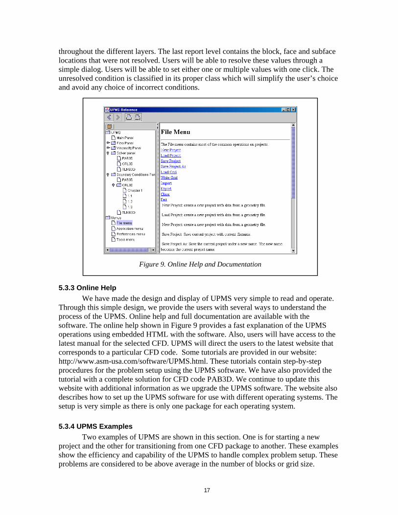
Figure 9. Online Help and Documentation
5.3.3 Online Help We have made the design and display of UPMS very simple to read and operate. Through this simple design, we provide the users with several ways to understand the process of the UPMS. Online help and full documentation are available with the software. The online help shown in Figure 9 provides a fast explanation of the UPMS operations using embedded HTML with the software. Also, users will have access to the latest manual for the selected CFD. UPMS will direct the users to the latest website that corresponds to a particular CFD code. Some tutorials are provided in our website: http://www.asm-usa.com/software/UPMS.html. These tutorials contain step-by-step procedures for the problem setup using the UPMS software. We have also provided the tutorial with a complete solution for CFD code PAB3D. We continue to update this website with additional information as we upgrade the UPMS software. The website also describes how to set up the UPMS software for use with different operating systems. The setup is very simple as there is only one package for each operating system.
5.3.4 UPMS Examples Two examples of UPMS are shown in this section. One is for starting a new
project and the other for transitioning from one CFD package to another. These examples show the efficiency and capability of the UPMS to handle complex problem setup. These problems are considered to be above average in the number of blocks or grid size.
17
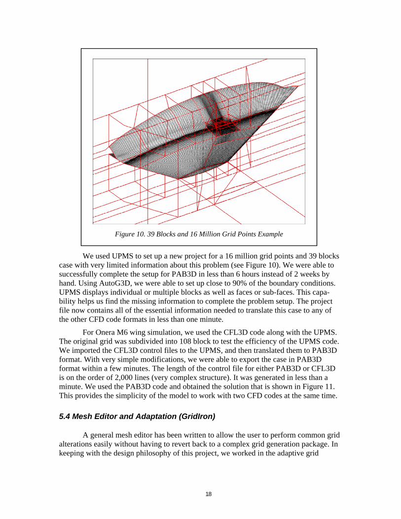
Figure 10. 39 Blocks and 16 Million Grid Points Example
We used UPMS to set up a new project for a 16 million grid points and 39 blocks case with very limited information about this problem (see Figure 10). We were able to successfully complete the setup for PAB3D in less than 6 hours instead of 2 weeks by hand. Using AutoG3D, we were able to set up close to 90% of the boundary conditions. UPMS displays individual or multiple blocks as well as faces or sub-faces. This capa-bility helps us find the missing information to complete the problem setup. The project file now contains all of the essential information needed to translate this case to any of the other CFD code formats in less than one minute.
For Onera M6 wing simulation, we used the CFL3D code along with the UPMS. The original grid was subdivided into 108 block to test the efficiency of the UPMS code. We imported the CFL3D control files to the UPMS, and then translated them to PAB3D format. With very simple modifications, we were able to export the case in PAB3D format within a few minutes. The length of the control file for either PAB3D or CFL3D is on the order of 2,000 lines (very complex structure). It was generated in less than a minute. We used the PAB3D code and obtained the solution that is shown in Figure 11. This provides the simplicity of the model to work with two CFD codes at the same time.
5.4 Mesh Editor and Adaptation (GridIron)
A general mesh editor has been written to allow the user to perform common grid alterations easily without having to revert back to a complex grid generation package. In keeping with the design philosophy of this project, we worked in the adaptive grid
18
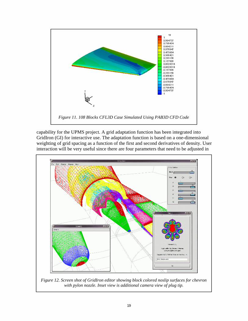
Figure 11. 108 Blocks CFL3D Case Simulated Using PAB3D CFD Code
capability for the UPMS project. A grid adaptation function has been integrated into GridIron (GI) for interactive use. The adaptation function is based on a one-dimensional weighting of grid spacing as a function of the first and second derivatives of density. User interaction will be very useful since there are four parameters that need to be adjusted in
Figure 12. Screen shot of GridIron editor showing block colored noslip surfaces for chevron with pylon nozzle. Inset view is additional camera view of plug tip.
19
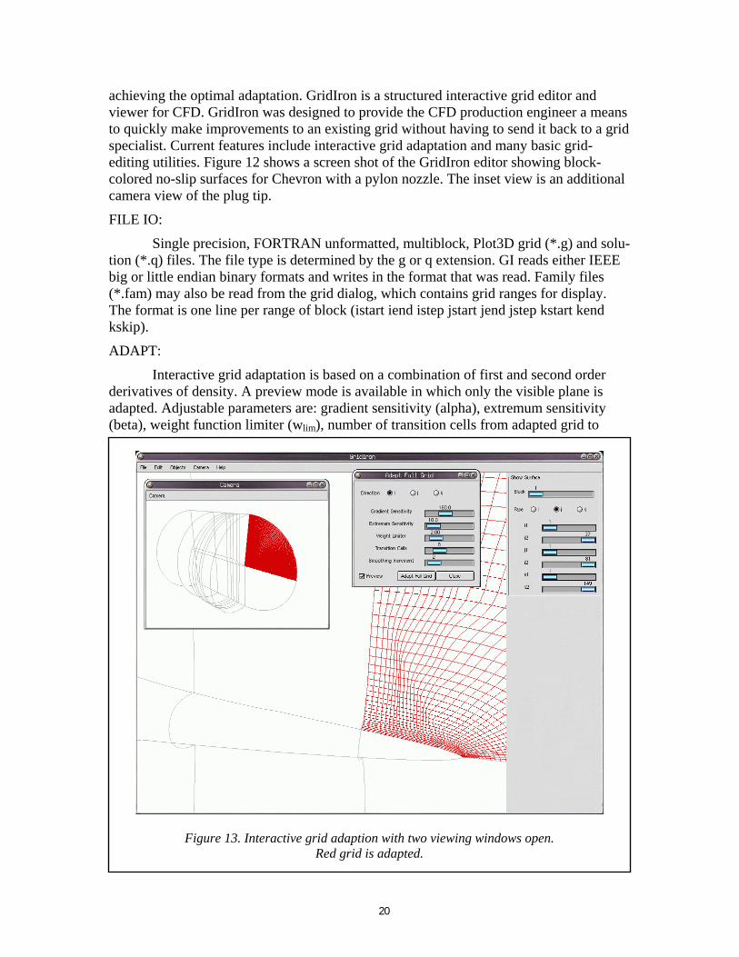
achieving the optimal adaptation. GridIron is a structured interactive grid editor and viewer for CFD. GridIron was designed to provide the CFD production engineer a means to quickly make improvements to an existing grid without having to send it back to a grid specialist. Current features include interactive grid adaptation and many basic grid-editing utilities. Figure 12 shows a screen shot of the GridIron editor showing block-colored no-slip surfaces for Chevron with a pylon nozzle. The inset view is an additional camera view of the plug tip.
FILE IO:
Single precision, FORTRAN unformatted, multiblock, Plot3D grid (*.g) and solu-tion (*.q) files. The file type is determined by the g or q extension. GI reads either IEEE big or little endian binary formats and writes in the format that was read. Family files (*.fam) may also be read from the grid dialog, which contains grid ranges for display. The format is one line per range of block (istart iend istep jstart jend jstep kstart kend kskip).
ADAPT:
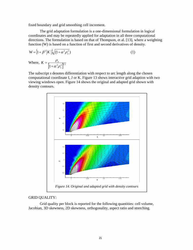
Interactive grid adaptation is based on a combination of first and second order derivatives of density. A preview mode is available in which only the visible plane is adapted. Adjustable parameters are: gradient sensitivity (alpha), extremum sensitivity (beta), weight function limiter (wlim), number of transition cells from adapted grid to
Figure 13. Interactive grid adaptiRed grid
on with two viewing windows open. is adapted.
20
fixed boundary and grid smoothing cell increment.
The grid adaptation formulation is a one-dimensional formulation in logical coordinates and may be repeatedly applied for adaptation in all three computational directions. The formulation is based on that of Thompson, et al. [13], where a weighting function (W) is based on a function of first and second derivatives of density.
{ } )1(1 W 222sK ραβ ++= (1)
Where, [ ] 5.1221 s
sKρα
ρ+
=
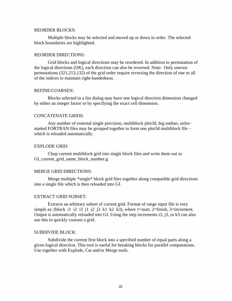
The subscript s denotes differentiation with respect to arc length along the chosen computational coordinate I, J or K. Figure 13 shows interactive grid adaption with two viewing windows open. Figure 14 shows the original and adapted grid shown with density contours.
Figure 14. Original and adapted grid with density contours
GRID QUALITY:
Grid quality per block is reported for the following quantities: cell volume, Jacobian, 3D skewness, 2D skewness, orthogonality, aspect ratio and stretching.
21
REORDER BLOCKS:
Multiple blocks may be selected and moved up or down in order. The selected block boundaries are highlighted.
REORDER DIRECTIONS:
Grid blocks and logical directions may be reordered. In addition to permutation of the logical directions (IJK), each direction can also be reversed. Note: Only uneven permutations (321,213,132) of the grid order require reversing the direction of one or all of the indices to maintain right-handedness.
REFINE/COARSEN:
Blocks selected in a list dialog may have one logical direction dimension changed by either an integer factor or by specifying the exact cell dimension.
CONCATENATE GRIDS:
Any number of external single precision, multiblock plot3d, big endian, unfor-matted FORTRAN files may be grouped together to form one plot3d multiblock file – which is reloaded automatically.
EXPLODE GRID:
Chop current multiblock grid into single block files and write them out as GI_current_grid_name_block_number.g
MERGE GRID DIRECTIONS:
Merge multiple *single* block grid files together along compatible grid directions into a single file which is then reloaded into GI.
EXTRACT GRID SUBSET:
Extracts an arbitrary subset of current grid. Format of range input file is very simple as: (block i1 i2 i3 j1 j2 j3 k1 k2 k3), where 1=start, 2=finish, 3=increment. Output is automatically reloaded into GI. Using the step increments i3, j3, or k3 can also use this to quickly coarsen a grid.
SUBDIVIDE BLOCK:
Subdivide the current first block into a specified number of equal parts along a given logical direction. This tool is useful for breaking blocks for parallel computations. Use together with Explode, Cat and/or Merge tools.
22
6.0 Assessment of Technical Merit The Phase II effort has demonstrated that the UPMS can be driven independently
by a machine portable, Java-based GUI. The UPMS allows simple and direct access to the numerous NASA research codes without any modifications whatsoever to the FORTRAN programs. In addition, the UPMS is designed for easy extension to incorporate more advanced CFD tools in Phase III. The development of the UPMS is complete, and includes:
1. Expert system which will guide the user through the different aspects of problem setup.
2. Capability to work with other CFD codes and also more utilities to enhance the pre-processing of CFD codes.
3. Online help, which gives the user recommendations and steps for using a particular CFD code.
4. Adaptive grid capability to accommodate the change in the flow condition.
During the entire development process, test validations were conducted on multiple operating systems. Test results indicate that the Java front runs on SGI, HP, SUN, Intel Linux, and Intel Windows 95/98/NT/2000. However, the portability of Java is not completely automatic. Some new features are added to the UPMS and they must be tested on all machines. UPMS uses Java 2 and the SWING API, which uses Motif and can also switch between Windows, Motif or Metal look and feels on any platform. The PAB3D, CFL3D and TLNS3D interfaces have been validated. No part of the UPMS software uses date/time functions and therefore the software is “Year 2000” compliant. Documentation for all applications is complete and the software is available online at http://www.asm-usa.com/software/UPMS.html.
7.0 Phase III Potential Work We are continually developing more utilities and enhancements to the CFD
capability at AS&M. As our revenue increases from UPMS and PAB3D sales and CFD support, AS&M will continue the development of more CFD tools. Design of new aerodynamic configuration requires the use of multidisciplinary computations. It may involve structural analysis, fluid dynamic simulation or heat transfer simulation and multidisciplinary analysis. The existing multidisciplinary programs are loosely coupled using shell scripts within the multi-program system [14-16]. Even within one discipline, different techniques must be used for efficient simulation. The enhancement of UPMS includes the development of a Multi-Program System (MPS) that utilizes the message passing interface (MPI) distributed computer library.
The object of the MPS element is to develop a general distributed computer system for using one- or multi-disciplinary programs on a network of a heterogeneous cluster of computers. References [15-16] introduce the distributed computing environ-ment for multidisciplinary programs. They have developed the Framework for Interdis-ciplinary Design Optimization (FIDO). The goal was to develop a general distributed computing system for executing multidisciplinary computations on a networked heter-ogeneous cluster of workstations and massively parallel computers. Salas and Townsend [16] have described the major limitation with the FIDO, which was developed for a specific application - the HSCT design. The sequence of processes is hard coded, making
23
it difficult to modify them. The lack of documentation and the application formulation has made FIDO inaccessible for use by researchers who did not participate in its development.
The UPMS capabilities can be further enhanced by adding the following features:
1. Perfect multiblock automatic patching with GUI is essential to being able to set up a new problem in very short time, i.e., a problem should be set up in minutes instead of hours.
2. Full capabilities of PAB3D/CFL3D/TLNS3D codes which should be exploited as part of the commercialization.
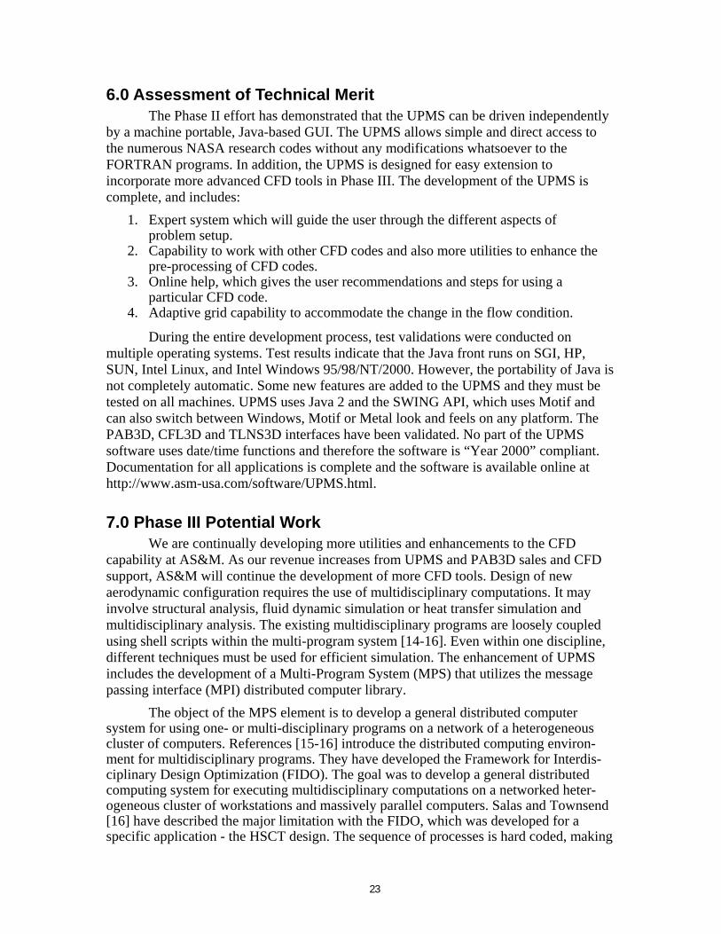
CFD Analysis Thermal Analysis
Structural Analysis
Figure 15. Expand the UPMS to More Disciplines
3. Tutorial and step-by-step examples for the novice user will make the UPMS a valuable tool for university and research organizations. The basic work of the UPMS is complete which makes it easier to add more CFD (including unstruc-tured) codes to the system.
4. The concept of UPMS can be used with other computational analysis methods such as structured and thermal analyses, as shown in Figure 15. Multi-disciplinary analysis becomes essential in the design of new aerospace configurations. UPMS can be a very promising approach in multi-disciplinary analysis.
AS&M plans to commercialize the UPMS and its derivatives by focusing on three
major areas: cost effectiveness, environmental friendliness, and customer requirements. AS&M realizes the scope of the commercialization effort and has outlined some of the major activities below. AS&M will conduct the majority of these milestone activities during the Phase III program.
1. Identify Potential Market Sectors and Customers: This activity of identifying the potential sectors and customers started soon after award of the Phase II program. We will continue the process of identifying other relevant marketing areas throughout the Phase III program and beyond.
2. License the Product: The most significant part of the revenues generated from the commercialization of UPMS will be from the licensing of the process to agencies/companies. Successful commercialization will depend on our ability to offer UPMS for use with a large number of NASA CFD codes.
The Phase II work clearly establishes technical merit of the expert UPMS approach. Phase III continuation of the UPMS development with expert guidance is
24

justified based on the successful construction of the basic UPMS. The Mesh Editor and adaptive grid are stand-alone utilities which can be used with any other multiblock CFD codes. This makes the UPMS ready to reach its goal toward a complete CFD system as it continually introduces new CFD tools. The UPMS is one of the first GUI interactive commercial products which can be used to set up a commercial CFD code (PAB3D) and NASA’s public domain CFD codes (CFL3D and TLNS3D).
25
8.0 References 1. White, J. and Morrison, J., “A Pseudo-Temporal Multi-Grid Relaxation Scheme for
Solving the Navier-Stokes Equations,” AIAA Paper No. 99-3360, June 1999. 2. Cheatwood, F. M. and Peter A. Gnoffo, P. A., “User’s Manual for the Langley
Aerothermodynamic Upwind Relaxation Algorithm (LAURA) ,” NASA TM-4674, April 1996, p. 223.
3. Rudy, D., “Validation Studies for CFL3D, CFL3DE, and GASP Codes,” Paper No. 115, 10th National AeroSpace Plane Technology Symposium, April 1991.
4. PAB3D Code Manual, Originally developed by the Propulsion Aerodynamics Branch, now under cooperative program between the Configuration Aerodynamics Branch, NASA Langley Research Center and Analytical Services & Materials, Inc. Hampton, VA. See http://www.asm-usa.com/software/pab3d.html.
5. CFL3D code, Computational Fluid Dynamics and Aero-Acoustics Branch, NASA Langley Research Center, Hampton, VA. See http://ad-www.larc.nasa.gov/tsab/cfdlarc/cfdlarc.html
6. USM3D code, Transonic/Supersonic Aerodynamics Branch, NASA Langley Research Center. See http://ad-www.larc.nasa.gov/tsab/cfdlarc/cfdlarc.html
7. TLNS3D code, Aerodynamic and Acoustic Methods Branch, NASA Langley Research Center. See http:// http://ad-www.larc.nasa.gov/tsab/cfdlarc/cfdlarc.html
8. OVERFLOW code, Configuration Aerodynamics Branch, NASA Langley Research Center. See http://ad-www.larc.nasa.gov/tsab/cfdlarc/cfdlarc.html
9. Jambunathan, K., Lai, E., Hartle, S. L., and Button, B. L., “Development of an Intelligent Front-End for a Computational Fluid Dynamics Package,” Artificial Intelligence in Engineering, Vol. 6, No. 1, 1991, pp. 27-35.
10. Ebrahimi, B. H., “An Efficient Two-Dimensional Engineering Design Code for Scramjet Combustor, Nozzle and Plume Analysis,” AIAA 91-0416, 1991.
11. Ebrahimi, B. H., and Gilbertson, M., “Two and Three Dimensional Parabolized Navier-Stokes Code for Scramjet Combuster, Nozzle and Film Cooling Analysis,” AIAA 92-0391, 1992.
12. Ebrahimi, H. B, “CFD Validation for Scramjet Combustor and Nozzle Flows, Part I,” AIAA 93-1840, 1993.
13. Thompson, J., Warsi, Z. and Mastin, C., “Numerical Grid Generation,” North-Holland, New York, 1978.
14. Rumsey, C. I., Biedron, R. T. and Thomas, J. L., “CFL3D: Its History and Some Recent Applications,” NASA TM-112861, 1997.
15. Weston, R. P., Townsead, J. C., Eidson, T. M., and Gates, R. L., “Distributed Computing Environment for Multidisciplinary,” 5th AIAA/NASA/ISSMO Symposium on Multidisciplinary Analysis and Optimization, AIAA 94-4372-CP, 1994, pp. 1091-1097.
16. Salas, A. O., and Townsend, J. C., “Framework Requirement for MDO Application Development,” AIAA 98-4740, 1998.
26
R E P O R T D O C U M E N T A T I O N P A G E
Form Approved OMB No. 0704-0188
Public Reporting burden for this collection of information is estimated to average 1 hour per response, including the time for reviewing instructions, searching existing data sources, gathering and maintaining the data needed, and completing and reviewing the collection of information. Send comments regarding this burden estimate or any other aspect of this collection of information, including suggestions for reducing this burden, to Washington Headquarters Services, Directorate for Information Operations and Reports, 1215 Jefferson Davis Highway, Suite 1204, Arlington, VA 22202-4302, and to the Office of Management and Budget, Paperwork Reduction Project (0704-0188), Washington, DC 20503. 1. AGENCY USE ONLY (Leave blank) 2. REPORT DATE
April 27, 2002 3. REPORT TYPE AND DATES COVERED
Final
4. TITLE AND SUBTITLE
Unified Process Management System for CFD 6. AUTHOR(S)
Dr. Khaled S. Abdol-Hamid, Dr. Steven J. Massey and Shane Caldwell
5. FUNDING NUMBERS
NAS1-00006
7. PERFORMING ORGANIZATION NAME(S) AND ADDRESS(ES)
Analytical Services & Materials, Inc. 107 Research Drive, Hampton, VA 23666-1340
8. PERFORMING ORGANIZATION REPORT NUMBER
RS02 (final)
9. SPONSORING/MONITORING AGENCY NAME(S) AND ADDRESS(ES)
NASA Langley Research Center Hampton, VA 23681-2199
10. SPONSORING/MONITORING AGENCY REPORT NUMBER
11. SUPPLEMENTARY NOTES
12a. DISTRIBUTION/AVAILABILITY STATEMENT (if contract specified restricted distribution, state restriction instead of Unclassified-Unlimited)
12b. DISTRIBUTION CODE
13. ABSTRACT (Maximum 200 words)
The Unified Process Management System (UPMS) is a valuable computational fluid dynamics (CFD) analysis tool that utilizes NASA’s CFD codes: PAB3D, CFL3D and TLNS3D. Each of these CFD codes has a specific format for input files. The choice of a particular CFD code depends upon its reliability, its ease of use and the availability of technical support. However, it is difficult to find a CFD code that combines all of these requirements for a specific class of problems. Even simple modifications in problem definition would require extensive alterations to these formats. Familiarization with more than one code becomes difficult when seeking CFD solutions for a particular configuration. The UPMS alleviates these difficulties with the use of an expert graphical user interface (GUI) system. The system also includes interactive adaptive grid capabilities and grid modification processes. The significance of this work is its flexibility in allowing these CFD grid structured codes to be coupled with the UPMS without any modifications whatsoever to the CFD solvers. It automatically generates documentation of code-independent project/problem setup in engineering terms, and writes code specific input files to drive the solver. The UPMS was written in the object-oriented and highly portable JAVA programming language.
(Provide an unclassified abstract not to exceed 200 words)
15. NUMBER OF PAGES
27 14. SUBJECT TERMS
Unified Process Management System, UPMS, Computational Fluid Dynamics, CFD, Graphical User Interface, GUI, PAB3D, CFL3D, TLNS3D 16. PRICE CODE
17. SECURITY CLASSIFICATION OF REPORT
Unclassified 18. SECURITY CLASSIFICATION OF THIS PAGE
Unclassified 19. SECURITY CLASSIFICATION OF ABSTRACT
Unclassified
20. LIMITATION OF ABSTRACT
Unlimited
NSN 7540-01-280-5500 Computer Generated STANDARD FORM 298 (Rev 2-89)
LaRC Overprint 1
Prescribed by ANSI Std 239-18 298-102
27