Embed Size (px)
Citation preview

UFC 4-740-16 25 May 2005
UNIFIED FACILITIES CRITERIA (UFC)
DESIGN: MILITARY RECREATION
CENTERS
APPROVED FOR PUBLIC RELEASE; DISTRIBUTION UNLIMITED
UFC 4-740-16 25 May 2005
UNIFIED FACILITIES CRITERIA (UFC)
DESIGN: MILITARY RECREATION CENTERS
Any copyrighted material included in this UFC is identified at its point of use. Use of the copyrighted material apart from this UFC must have the permission of the copyright holder. U.S. ARMY CORPS OF ENGINEERS NAVAL FACILITIES ENGINEERING COMMAND (Preparing Activity) AIR FORCE CIVIL ENGINEER SUPPORT AGENCY Record of Changes (changes are indicated by \1\ ... /1/) Change No. Date Location

UFC 4-740-16 25 May 2005
FOREWORD The Unified Facilities Criteria (UFC) system is prescribed by MIL-STD 3007 and provides planning, design, construction, sustainment, restoration, and modernization criteria, and applies to the Military Departments, the Defense Agencies, and the DoD Field Activities in accordance with USD(AT&L) Memorandum dated 29 May 2002. UFC will be used for all DoD projects and work for other customers where appropriate. All construction outside of the United States is also governed by Status of forces Agreements (SOFA), Host Nation Funded Construction Agreements (HNFA), and in some instances, Bilateral Infrastructure Agreements (BIA.) Therefore, the acquisition team must ensure compliance with the more stringent of the UFC, the SOFA, the HNFA, and the BIA, as applicable. UFC are living documents and will be periodically reviewed, updated, and made available to users as part of the Services’ responsibility for providing technical criteria for military construction. Headquarters, U.S. Army Corps of Engineers (HQUSACE), Naval Facilities Engineering Command (NAVFAC), and Air Force Civil Engineer Support Agency (AFCESA) are responsible for administration of the UFC system. Defense agencies should contact the preparing service for document interpretation and improvements. Technical content of UFC is the responsibility of the cognizant DoD working group. Recommended changes with supporting rationale should be sent to the respective service proponent office by the following electronic form: Criteria Change Request (CCR). The form is also accessible from the Internet sites listed below. UFC are effective upon issuance and are distributed only in electronic media from the following source: • Whole Building Design Guide web site http://dod.wbdg.org/. Hard copies of UFC printed from electronic media should be checked against the current electronic version prior to use to ensure that they are current. AUTHORIZED BY: ______________________________________ DONALD L. BASHAM, P.E. Chief, Engineering and Construction U.S. Army Corps of Engineers
______________________________________DR. JAMES W WRIGHT, P.E. Chief Engineer Naval Facilities Engineering Command
______________________________________ KATHLEEN I. FERGUSON, P.E. The Deputy Civil Engineer DCS/Installations & Logistics Department of the Air Force
______________________________________Dr. GET W. MOY, P.E. Director, Installations Requirements and Management Office of the Deputy Under Secretary of Defense (Installations and Environment)

UFC 4-740-16 25 May 2005
MILITARY RECREATION CENTER
TABLE OF CONTENTS
CHAPTER 1. INTRODUCTION Paragraph 1-1 Scope of Document ................................................................... 1-1 1-2 Users of this Document ............................................................. 1-1 1-2.1 Architects and Engineers........................................................... 1-1 1-2.2 Planning Personnel ................................................................... 1-1 1-2.3 Additional Users ........................................................................ 1-1 1-3 Scope of Facility ........................................................................ 1-2 1-3.1 Core Spaces.............................................................................. 1-2 1-3.2 Optional Spaces ........................................................................ 1-2 1-4 Users of Facility ......................................................................... 1-3 1-5 Related Documents................................................................... 1-3 1-6 Related Facilities ....................................................................... 1-3 CHAPTER 2. GENERAL DESIGN CRITERIA Paragraph 2-1 Master/Site Planning ................................................................. 2-1 2-1.1 Size Determinants ..................................................................... 2-1 2-1.2 Space Programs........................................................................ 2-2 2-1.3 Location Determinants............................................................... 2-2 2-2 Layout and Adjacencies .......................................................... 2-10 2-2.1 Functional Relationship Bubble Diagram................................. 2-10 2-2.2 Quiet vs. Active Functions ....................................................... 2-10 2-2.3 Space Assessment.................................................................. 2-12 2-3 Alterations to Existing Facilities ............................................... 2-11 2-3.1 Regulatory Authorities ............................................................. 2-11 2-3.2 Other Considerations............................................................... 2-11 2-3.3 Codes ...................................................................................... 2-12 2-4 Exterior Design........................................................................ 2-12 2-4.1 Structure.................................................................................. 2-12 2-4.2 Exterior Finishes...................................................................... 2-12 2-5 Interior Design ......................................................................... 2-12 2-6 Services................................................................................... 2-12 2-6.1 Plumbing ................................................................................. 2-12 2-6.2 Heating, Ventilating, and Air Conditioning ............................... 2-12 2-6.3 Fire Protection ......................................................................... 2-13 2-6.4 Electrical.................................................................................. 2-13 2-7 Site Work................................................................................. 2-14 2-7.1 Landscaping ............................................................................ 2-14 2-7.2 Site Lighting............................................................................. 2-14 2-7.3 Outdoor Activities .................................................................... 2-14 2-8 Barrier Free Design Requirements.......................................... 2-14
i

UFC 4-740-16 25 May 2005
2-9 Anti-Terrorism/Force Protection .............................................. 2-14 2-10 Sustainable Design ................................................................. 2-14 2-10.1 The United States Green Building Council LEEDTM Green Building Rating System ........................................................... 2-14 2-10.2 ITG FY92 – 02 Design Energy Target Reductions, NAVFAC Interim Technical Guidance..................................................... 2-14 2-10.3 EPA List of Affirmative Procurement Guideline Items.............. 2-14 2-10.4 Whole Building Design Guide.................................................. 2-15 2-10.5 DoD Energy Budget................................................................. 2-15 CHAPTER 3. FUNCTIONAL CRITERIA Paragraph 3-1 Functional Data Sheets ............................................................. 3-1 APPENDIX A REFERENCES..........................................................................A-1
ii

UFC 4-740-16 25 May 2005
FIGURES
Figure Title 2-1 Functional Relationship Bubble Diagram.............................................. 2-11
TABLES Table Title 2-1 Size Classifications................................................................................. 2-1 2-2 Space Program for Extra Small Installation ............................................ 2-3 2-3 Space Program for Small Installation...................................................... 2-4 2-4 Space Program for Medium Installation .................................................. 2-5 2-5 Space Program for Large Installation ..................................................... 2-6 2-6 Space Program for Extra Large Installation ............................................ 2-7 2-7 Space Program for Super Large Installation ........................................... 2-8 2-8 Space Program for Extra Small Installation (Optional Spaces)............... 2-9 2-9 Space Program for Small Installation (Optional Spaces) ........................ 2-9 2-10 Space Program for Medium Installation (Optional Spaces) .................... 2-9 2-11 Space Program for Large Installations (Optional Spaces) .................... 2-10 2-12 Space Program for Extra Large and Super Large Installations (Optional Spaces) ................................................................................. 2-10 3-1 Lobby/Entrance....................................................................................... 3-1 3-2 Customer Service Area/Control .............................................................. 3-2 3-3 Server Room........................................................................................... 3-3 3-4 Computer Room ..................................................................................... 3-4 3-5 Game Room ........................................................................................... 3-5 3-6 Mini Theater............................................................................................ 3-6 3-7 TV Lounge .............................................................................................. 3-7 3-8 Snack/Vending........................................................................................ 3-8 3-9 Food Service Area .................................................................................. 3-9 3-10 Library/Quiet Room............................................................................... 3-10 3-11 Multipurpose Room............................................................................... 3-11 3-12 Personal Storage Lockers..................................................................... 3-12 3-13 Laundry................................................................................................. 3-13 3-14 Individual TV Room .............................................................................. 3-14 3-15 Music Listening ..................................................................................... 3-15 3-16 Music Practice Room(s) ....................................................................... 3-16 3-17 Outdoor Gathering Area........................................................................ 3-17 3-18 Pay Telephones.................................................................................... 3-18 3-19 Staff Offices .......................................................................................... 3-19 3-20 Toilets (male and female) .................................................................... 3-20
iii

UFC 4-740-16 25 May 2005
CHAPTER 1
INTRODUCTION
1-1 SCOPE OF DOCUMENT. This UFC provides guidelines for evaluating, planning, and designing Military Recreation Centers (MRCs). The information in this Guide applies to the design of all new construction projects as well as renovation projects. Renovation projects should update existing facilities to meet the guidance and criteria within budgetary constraints. This guide is not intended as a substitution during design for thorough review by individual Program Managers and Operations Staff in the appropriate Service.
1-2 USERS OF THIS DOCUMENT. This UFC is intended to be a source of basic architectural information for all individuals involved in the planning, design, or evaluation of MRC facilities. Note: where one Service's criteria vary from the other Services' criteria, it is noted in the text with the (Service Exception) symbol. Specific users of the Guide include the following:
1-2.1 Architects and Engineers. Architects and Engineers (A/Es) and Design/Build contractors providing design services under the direction of the individual design agencies, including the Naval Facilities Engineering Command (NAVFAC), Navy Personnel Command (NPC), Community and Family Support Center (CFSC), and Army and Air Force Exchange Service (AAFES). All DoD facilities must meet the basic building requirements of UFC 1-200-01.
1-2.2 Planning Personnel. Planning Personnel will use the Guide for pre-design planning or to assess the extent of improvements required in an existing MRC in order to achieve the standard established herein.
1-2.3 Additional Users. Additional users include the following:
• Headquarters Staff
• Major Command Staff
• Installation Commanders
• Installation Facilities Management
• Installation Technical Proponents
• Program Directors
• Facility/Program Operations Staff
1-1

UFC 4-740-16 25 May 2005
1-3 SCOPE OF FACILITY. The MRC is a social and recreational center primarily for use by single and unaccompanied enlisted military personnel. It is intended to provide alcohol-free and tobacco-free recreational alternatives for 17- to 25-year olds.
In certain cases, the Marine Corps may allow alcohol in their facilities. The Navy may also call these LIBERTY or Single Sailor Centers. The Marine Corps may also call these Single Marine Centers.
The MRC includes certain core spaces that provide for both individual and group functions in an environment that is comfortable and conducive to interaction, either physical or visual. It also includes support spaces and may include optional or additional spaces that complement the core spaces.
1-3.1 Core Spaces. Include the following core spaces to classify the facility as a MRC. More complete descriptions of these spaces may be found in Chapter 3.
• Customer Service Area/Control Counter
• Computer Area
• Game Area (both table gaming and video gaming)
• Mini-theater
• TV Lounge
• Snack/Vending Area
• Library/Quiet Space
• Multipurpose Room Core for Marine Corps only
1-3.2 Optional Spaces. Consider the following non-essential (optional) spaces as they complement the core spaces or offer additional functionality. See paragraph 2-1.1.2 for more information on how to select optional spaces for a facility.
• Multipurpose Room
• Mini Personal Storage
• Automatic Teller Machine (ATM) (in lobby)
• Laundry
• Food Service not permitted for Navy
• Coffee Bar
1-2

UFC 4-740-16 25 May 2005
• Individual TV viewing stations
• Music Listening Area
• Music Practice Room
• Outdoor Gathering Area
• Pay Telephone Room (for Large, Extra Large, and Super Large facilities only)
1-4 USERS OF FACILITY. The following facility users are listed in order of most likely usage (i.e. target audience):
• 17- to 25-year old, single or unaccompanied, enlisted military personnel;
• Facility Staff; and
• All other active duty military personnel.
1-5 RELATED DOCUMENTS. This UFC augments the Navy: Liberty Program Accreditation MWR Standards and Metrics Document prepared by the PERS-654, July 2001. Marine Corps: Semper Fit MCO P1700.29 and SMP MCO P1700.36. Used together, these documents form the Program Document. For additional information see Navy document P-80.
1-6 RELATED FACILITIES. There are other facilities that single enlisted military personnel could use but are not the focus of the program. These facilities complement the MRC program but play a different role in the social environment of a base. The MRC is distinct from these other programs in that it primarily targets 17- to 25-year old, single or unaccompanied, enlisted military personnel. Related facilities include the following:
• Fleet Recreation Center;
• Outdoor Adventure Centers and Rental Centers;
• Information/Tickets and Tours (ITT);
• Amusement Center;
• Fitness Center;
• Bowling Center;
• Base Theater;
• Base Library; and
1-3

UFC 4-740-16 25 May 2005
• Clubs.
1-4

UFC 4-740-16 25 May 2005
CHAPTER 2
GENERAL DESIGN CRITERIA
2-1 MASTER/SITE PLANNING.
2-1.1 Size Determinants. Several factors determine the size of the facility.
2-1.1.1 Size Classifications. The facility size classifications and the active duty populations they serve are shown in Table 2-1. The size of the facility is based, in part, on this active duty population. When the total population is broken down into distinctive geographic locations, consider providing multiple facilities sized individually for the geographic populations.
TABLE 2-1. SIZE CLASSIFICATIONS
Size Classification Active Duty Population Served Super Large > 50,000 Extra Large 14,001 – 50,000 Large 7,001 – 14,000 Medium 3,001 – 7,000 Small 500 – 3,000 Extra Small (OCONUS Only) < 500
2-1.1.2 Optional Spaces. Once the size classification has been determined, determine which optional activity spaces to include (see paragraph 1-3 for more information on optional activities). The Base representatives, in conjunction with the project manager, must decide which optional activity spaces to provide. Note the following when selecting optional activities:
2-1.1.2.1 If an existing facility is being renovated to accommodate the MRC function, the amount of space available will likely determine what options may be provided. Note that the existing facility must accommodate the core activity spaces to be considered for use as an MRC. See paragraph 2-3 for more information on alterations to existing facilities.
2-1.1.2.2 Consider what functions are provided in existing facilities on the installation and the proximity of those existing facilities to the new MRC.
2-1.1.2.3 Consider what can be provided within the budget.
2-1.1.2.4 For Navy facilities, avoid providing optional spaces that may be commandeered for mission-oriented functions (i.e., a multipurpose room that might be commandeered for use a meeting facility).
2-1

UFC 4-740-16 25 May 2005
2-1.2 Space Programs. Once the size classification has been determined and the optional activities selected, Tables 2-2 through 2-7 illustrate the size programs for the minimum facilities by size classification, including core activities, activity support functions, and site support. Tables 2-8 through 2-12 illustrate the space programs for the optional activity spaces by size classification. The selected optional activity spaces must be added to the minimum facilities to determine the total space program for the facility. These tables (spreadsheets) are available as downloadable Microsoft© Excel© files to be used as an interactive tool on the Whole Building Design Guide DoD page (http://dod.wbdg.org/) website.
2-1.3 Location Determinants. The Master/Site Planning determinants in paragraphs 2-1.3.1 through 2-1.3.3 must be weighed together when selecting the most appropriate and cost effective location for an MRC. The success of the MRC has a great deal to do with the convenience of its location as it relates to its function. Therefore, while cost is critical in the development of the MRC model, a low cost should not be the sole determinant in locating an MRC.
2-1.3.1 Existing Space Types. Prior to initiating the physical planning of the MRC itself, complete a space type analysis of the existing base. The purpose of this analysis is to identify the following:
• Existing base functions which are core elements to an MRC,
• Existing base functions which are identical to other space types generally associated with an MRC but not core elements, and
• Existing base functions that are similar and compatible with the function of an MRC. See Section 1-6 for a list of related facilities.
2-1.3.2 Access. The MRC should be the hub of the MWR/MCCS activities for the enlisted personnel. Choose a location that encourages participation by a diverse representation of the target audience, including both genders, by being visible and easily accessible. Consider locating near other high-visibility areas and related functions. This could be along the pedestrian paths to the existing barracks, existing MWR/NEX/MCCS facilities, and/or the dining facility. Also consider proximity to any concentration of afloat units. To accommodate patron access, provide adequate parking as close as possible to the facility, taking into account the antiterrorism requirements in UFC 4-010-01.
2-2

UFC 4-740-16 25 May 2005
TABLE 2-2. SPACE PROGRAM FOR EXTRA SMALL INSTALLATION 0.0929
Functional Component m2 ft.2 Standard No. m2 ft.2Customer Service Area/Control
Customer Interface 3.72 40 per staff member 1 3.72 40ITT Kiosk 0.93 10 per kiosk 1 0.93 10Check-out Equipment Storage 0.74 8 per under counter unit 1 0.74 8Tape Storage/Theatre Equipment 0.74 8 per rack/140 tapes 2 1.49 16
Server Room 5.95 64 per room 1 5.95 64Computer Area
Workstations 1.39 15 per workstation 8 11.15 120Control/Help Counter 7.43 80 per control counter 0 0.00 0
Game Room Video Game Stations 10.22 110 per video station 4 40.88 440Pinball/Arcade Stations 1.39 15 per machine 4 5.57 60Pool Tables 32.52 350 per table 1 32.52 350Ping Pong/Table Tennis 29.26 315 per table 1 29.26 315FoosballAir Hockey 3.25 35 per table 1 3.25 35
Mini Theatre 2.79 30 per person 10 27.87 300TV Lounge 2.32 25 per person 12 27.87 300Snack/Vending
Vending 1.67 18 per vending machine 4 6.69 72Seating 4.46 48 per 4 seat table 1 4.46 48
Library/Quiet Area Books/Shelves 2.32 25 per shelf unit 2 4.65 50Reading/Writing 2.04 22 per person 6 12.26 132
Multipurpose Room * Multipurpose Room 2.79 30 per person 20 55.74 600Multipurpose Storage 9.29 100 per room 1 9.29 100
Staff Offices 0Program Manager 11.15 120 per office 1 11.15 120Program Assistant 7.43 80 per workstation 0 0.00 0Program Leader 7.43 80 per workstation 0 0.00 0Recreation Aide 0.00 0 per workstation 0 0.00 0
Pay Telephones 0.56 6 per phone 2 1.11 12Entrance Lobby 11.15 120 per lobby 1 11.15 120General Activity Storage 2.79 30 per room 1 2.79 30Office Storage 5.57 60 per room 1 5.57 60Toilets (Male and Female) 0
Water Closets/Urinals 2.32 25 per fixture 2 4.65 50Lavatories 1.39 15 per fixture 2 2.79 30Janitor's Closet 3.72 40 per closet 1 3.72 40
Total Building Net Area-Core Spaces & Support 327.20 3,522 Circulation and Mechanical Building Factor @ 15% 49.08 528
Total Building Gross Area-Core Spaces & Support 376.28 4,050Staff Parking 41.81 450 per space 3 125.42 1,350Passenger Van Parking 55.74 600 per space 1 55.74 600Patron Parking
Surfaced 41.81 450 per space 45 1,881.23 20,250Unsurfaced/Overflow 41.81 450 per space 45 1,881.23 20,250
Bicycle Racks 5.57 60 per 10-bike Rack 1 5.57 60Bus Stop/Transportation Transfer 18.58 200 per shelter 1 18.58 200
Total Site Support 3,967.76 42,710Total Facility (Building Gross Core Spaces and Site) 4,344.04 46,760
Extra Small InstallationSpace Allocation Standard
Cor
e A
ctiv
ity A
reas
Act
ivity
Sup
port
Site
Sup
port
* Multipurpose Room is optional for Navy. If this is removed from the space program, be sure to remove both the room and storage allocation and the 15% building factor on those spaces.
2-3

UFC 4-740-16 25 May 2005
TABLE 2-3. SPACE PROGRAM FOR SMALL INSTALLATION 0.0929
Functional Component m2 ft.2 Standard No. m2 ft.2Customer Service Area/Control
Customer Interface 3.72 40 per staff member 1 3.72 40ITT Kiosk 0.93 10 per kiosk 1 0.93 10Check-out Equipment Storage 0.74 8 per under counter unit 1 0.74 8Tape Storage/Theatre Equipment 0.74 8 per rack/140 tapes 2 1.49 16
Server Room 5.95 64 per room 1 5.95 64Computer Area
Workstations 1.39 15 per workstation 12 16.72 180Control/Help Counter 7.43 80 per control counter 0 0.00 0
Game RoomVideo Game Stations 10.22 110 per video station 4 40.88 440Pinball/Arcade Stations 1.39 15 per machine 4 5.57 60Pool Tables 32.52 350 per table 2 65.03 700Ping Pong/Table Tennis 29.26 315 per table 1 29.26 315FoosballAir Hockey 3.25 35 per table 1 3.25 35
Mini Theatre 2.79 30 per person 20 55.74 600TV Lounge 2.32 25 per person 12 27.87 300Snack/Vending
Vending 1.67 18 per vending machine 4 6.69 72Seating 4.46 48 per 4 seat table 1 4.46 48
Library/Quiet AreaBooks/Shelves 2.32 25 per shelf unit 2 4.65 50Reading/Writing 2.04 22 per person 6 12.26 132
Multipurpose Room *Multipurpose Room 2.79 30 per person 30 83.61 900Multipurpose Storage 9.29 100 per room 1 9.29 100
Staff OfficesProgram Manager 11.15 120 per office 1 11.15 120Program Assistant 7.43 80 per workstation 0 0.00 0Program Leader 7.43 80 per workstation 0 0.00 0Recreation Aide 0.00 0 per workstation 1 0.00 0
Pay Telephones 0.56 6 per phone 2 1.11 12Entrance Lobby 11.15 120 per lobby 1 11.15 120General Activity Storage 2.79 30 per room 1 2.79 30Office Storage 5.57 60 per room 1 5.57 60Toilets (Male and Female)
Water Closets/Urinals 2.32 25 per fixture 4 9.29 100Lavatories 1.39 15 per fixture 4 5.57 60Janitor's Closet 3.72 40 per closet 1 3.72 40
Total Building Net Area-Core Spaces & Support 428.45 4,612 Circulation and Mechanical Building Factor @ 15% 64.27 692
Total Building Gross Area-Core Spaces & Support 492.72 5,304Staff Parking 41.81 450 per space 3 125.42 1,350Passenger Van Parking 55.74 600 per space 1 55.74 600Patron Parking
Surfaced 41.81 450 per space 45 1,881.23 20,250Unsurfaced/Overflow 41.81 450 per space 45 1,881.23 20,250
Bicycle Racks 5.57 60 per 10-bike Rack 1 5.57 60Bus Stop/Transportation Transfer 18.58 200 per shelter 1 18.58 200
Total Site Support 3,967.76 42,710Total Facility (Building Gross Core Spaces and Site) 4,460.48 48,014
Space Allocation Standard Small Installation
Cor
e A
ctiv
ity A
reas
Act
ivity
Sup
port
Site
Sup
port
* Multipurpose Room is optional for Navy. If this is removed from the space program, be sure to remove both the room and storage allocation and the 15% building factor on those spaces.
2-4

UFC 4-740-16 25 May 2005
TABLE 2-4. SPACE PROGRAM FOR MEDIUM INSTALLATION 0.0929
Functional Component m2 ft.2 Standard No. m2 ft.2Customer Service Area/Control
Customer Interface 3.72 40 per staff member 2 7.43 80ITT Kiosk 0.93 10 per kiosk 1 0.93 10Check-out Equipment Storage 0.74 8 per under counter unit 2 1.49 16Tape Storage/Theatre Equipment 0.74 8 per rack/140 tapes 3 2.23 24
Server Room 5.95 64 per room 2 11.89 128Computer Area
Workstations 1.39 15 per workstation 16 22.30 240Control/Help Counter 7.43 80 per control counter 1 7.43 80
Game RoomVideo Game Stations 10.22 110 per video station 8 81.75 880Pinball/Arcade Stations 1.39 15 per machine 6 8.36 90Pool Tables 32.52 350 per table 4 130.06 1,400Ping Pong/Table Tennis 29.26 315 per table 1 29.26 315FoosballAir Hockey 3.25 35 per table 1 3.25 35
Mini Theatre 2.79 30 per person 36 100.33 1,080TV Lounge 2.32 25 per person 16 37.16 400Snack/Vending
Vending 1.67 18 per vending machine 6 10.03 108Seating 4.46 48 per 4 seat table 2 8.92 96
Library/Quiet AreaBooks/Shelves 2.32 25 per shelf unit 3 6.97 75Reading/Writing 2.04 22 per person 8 16.35 176
Multipurpose Room *Multipurpose Room 2.79 30 per person 40 111.48 1,200Multipurpose Storage 9.29 100 per room 1 9.29 100
Staff OfficesProgram Manager 11.15 120 per office 1 11.15 120Program Assistant 7.43 80 per workstation 1 7.43 80Program Leader 7.43 80 per workstation 1 7.43 80Recreation Aide 0.00 0 per workstation 1 0.00 0
Pay Telephones 0.56 6 per phone 3 1.67 18Entrance Lobby 11.15 120 per lobby 1 11.15 120General Activity Storage 2.79 30 per room 2 5.57 60Office Storage 5.57 60 per room 2 11.15 120Toilets (Male and Female)
Water Closets/Urinals 2.32 25 per fixture 12 27.87 300Lavatories 1.39 15 per fixture 12 16.72 180Janitor's Closet 3.72 40 per closet 1 3.72 40
Total Building Net Area-Core Spaces & Support 710.78 7,651 Circulation and Mechanical Building Factor @ 15% 106.62 1,148
Total Building Gross Area-Core Spaces & Support 817.39 8,799Staff Parking 41.81 450 per space 5 209.03 2,250Passenger Van Parking 55.74 600 per space 1 55.74 600Patron Parking
Surfaced 41.81 450 per space 70 2,926.35 31,500Unsurfaced/Overflow 41.81 450 per space 70 2,926.35 31,500
Bicycle Racks 5.57 60 per 10-bike Rack 2 11.15 120Bus Stop/Transportation Transfer 18.58 200 per shelter 1 18.58 200
Total Site Support 6,147.19 66,170Total Facility (Building Gross Core Spaces and Site) 6,964.59 74,969
Space Allocation Standard Medium Installation
Cor
e A
ctiv
ity A
reas
Act
ivity
Sup
port
Site
Sup
port
* Multipurpose Room is optional for Navy. If this is removed from the space program, be sure to remove both the room and storage allocation and the 15% building factor on those spaces.
2-5

UFC 4-740-16 25 May 2005
TABLE 2-5. SPACE PROGRAM FOR LARGE INSTALLATION 0.0929
Functional Component m2 ft.2 Standard No. m2 ft.2Customer Service Area/Control
Customer Interface 3.72 40 per staff member 2 7.43 80ITT Kiosk 0.93 10 per kiosk 2 1.86 20Check-out Equipment Storage 0.74 8 per under counter unit 3 2.23 24Tape Storage/Theatre Equipment 0.74 8 per rack/140 tapes 4 2.97 32
Server Room 5.95 64 per room 2 11.89 128Computer Area
Workstations 1.39 15 per workstation 24 33.44 360Control/Help Counter 7.43 80 per control counter 1 7.43 80
Game RoomVideo Game Stations 10.22 110 per video station 10 102.19 1,100Pinball/Arcade Stations 1.39 15 per machine 8 11.15 120Pool Tables 32.52 350 per table 6 195.09 2,100Ping Pong/Table Tennis 29.26 315 per table 2 58.53 630FoosballAir Hockey 3.25 35 per table 2 6.50 70
Mini Theatre 2.79 30 per person 48 133.78 1,440TV Lounge 2.32 25 per person 20 46.45 500Snack/Vending
Vending 1.67 18 per vending machine 8 13.38 144Seating 4.46 48 per 4 seat table 3 13.38 144
Library/Quiet AreaBooks/Shelves 2.32 25 per shelf unit 5 11.61 125Reading/Writing 2.04 22 per person 10 20.44 220
Multipurpose Room *Multipurpose Room 2.79 30 per person 50 139.35 1,500Multipurpose Storage 9.29 100 per room 2 18.58 200
Staff OfficesProgram Manager 11.15 120 per office 1 11.15 120Program Assistant 7.43 80 per workstation 1 7.43 80Program Leader 7.43 80 per workstation 1 7.43 80Recreation Aide 0.00 0 per workstation 2 0.00 0
Pay Telephones 0.56 6 per phone 4 2.23 24Entrance Lobby 11.15 120 per lobby 2 22.30 240General Activity Storage 2.79 30 per room 3 8.36 90Office Storage 5.57 60 per room 2 11.15 120Toilets (Male and Female)
Water Closets/Urinals 2.32 25 per fixture 16 37.16 400Lavatories 1.39 15 per fixture 16 22.30 240Janitor's Closet 3.72 40 per closet 1 3.72 40
Total Building Net Area-Core Spaces & Support 970.90 10,451 Circulation and Mechanical Building Factor @ 15% 145.63 1,568
Total Building Gross Area-Core Spaces & Support 1,116.53 12,019Staff Parking 41.81 450 per space 6 250.83 2,700Passenger Van Parking 55.74 600 per space 2 111.48 1,200Patron Parking
Surfaced 41.81 450 per space 98 4,096.89 44,100Unsurfaced/Overflow 41.81 450 per space 98 4,096.89 44,100
Bicycle Racks 5.57 60 per 10-bike Rack 3 16.72 180Bus Stop/Transportation Transfer 18.58 200 per shelter 1 18.58 200
Total Site Support 8,591.39 92,480Total Facility (Building Gross Core Spaces and Site) 9,707.92 104,499
Space Allocation Standard Large Installation
Cor
e A
ctiv
ity A
reas
Act
ivity
Sup
port
Site
Sup
port
* Multipurpose Room is optional for Navy. If this is removed from the space program, be sure to remove both the room and storage allocation and the 15% building factor on those spaces.
2-6

UFC 4-740-16 25 May 2005
TABLE 2-6. SPACE PROGRAM FOR EXTRA LARGE INSTALLATION 0.0929
Functional Component m2 ft.2 Standard No. m2 ft.2Customer Service Area/Control
Customer Interface 3.72 40 per staff member 3 11.15 120ITT Kiosk 0.93 10 per kiosk 2 1.86 20Check-out Equipment Storage 0.74 8 per under counter unit 4 2.97 32Tape Storage/Theatre Equipment 0.74 8 per rack/140 tapes 5 3.72 40
Server Room 5.95 64 per room 3 17.84 192Computer Area
Workstations 1.39 15 per workstation 60 83.61 900Control/Help Counter 7.43 80 per control counter 2 14.86 160
Game RoomVideo Game Stations 10.22 110 per video station 12 122.63 1,320Pinball/Arcade Stations 1.39 15 per machine 10 13.94 150Pool Tables 32.52 350 per table 8 260.12 2,800Ping Pong/Table Tennis 29.26 315 per table 3 87.79 945FoosballAir Hockey 3.25 35 per table 4 13.01 140
Mini Theatre 2.79 30 per person 60 167.22 1,800TV Lounge 2.32 25 per person 27 62.71 675Snack/Vending
Vending 1.67 18 per vending machine 10 16.72 180Seating 4.46 48 per 4 seat table 4 17.84 192
Library/Quiet AreaBooks/Shelves 2.32 25 per shelf unit 10 23.23 250Reading/Writing 2.04 22 per person 12 24.53 264
Multipurpose Room *Multipurpose Room 2.79 30 per person 60 167.22 1,800Multipurpose Storage 9.29 100 per room 2 18.58 200
Staff OfficesProgram Manager 11.15 120 per office 2 22.30 240Program Assistant 7.43 80 per workstation 2 14.86 160Program Leader 7.43 80 per workstation 3 22.30 240Recreation Aide 0.00 0 per workstation 3 0.00 0
Pay Telephones 0.56 6 per phone 6 3.34 36Entrance Lobby 11.15 120 per lobby 3 33.44 360General Activity Storage 2.79 30 per room 4 11.15 120Office Storage 5.57 60 per room 4 22.30 240Toilets (Male and Female)
Water Closets/Urinals 2.32 25 per fixture 22 51.10 550Lavatories 1.39 15 per fixture 22 30.66 330Janitor's Closet 3.72 40 per closet 1 3.72 40
Total Building Net Area-Core Spaces & Support 1,346.68 14,496 Circulation and Mechanical Building Factor @ 15% 202.00 2,174
Total Building Gross Area-Core Spaces & Support 1,548.68 16,670Staff Parking 41.81 450 per space 11 459.86 4,950Passenger Van Parking 55.74 600 per space 3 167.22 1,800Patron Parking
Surfaced 41.81 450 per space 132 5,518.26 59,400Unsurfaced/Overflow 41.81 450 per space 132 5,518.26 59,400
Bicycle Racks 5.57 60 per 10-bike Rack 3 16.72 180Bus Stop/Transportation Transfer 18.58 200 per shelter 1 18.58 200
Total Site Support 11,698.90 125,930Total Facility (Building Gross Core Spaces and Site) 13,247.58 142,600
Extra Large InstallationSpace Allocation Standard
Cor
e A
ctiv
ity A
reas
Act
ivity
Sup
port
Site
Sup
port
* Multipurpose Room is optional for Navy. If this is removed from the space program, be sure to remove both the room and storage allocation and the 15% building factor on those spaces.
2-7

UFC 4-740-16 25 May 2005
TABLE 2-7. SPACE PROGRAM FOR SUPER LARGE INSTALLATION 0.0929
Functional Component m2 ft.2 Standard No. m2 ft.2Customer Service Area/Control
Customer Interface 3.72 40 per staff member 3 11.15 120ITT Kiosk 0.93 10 per kiosk 2 1.86 20Check-out Equipment Storage 0.74 8 per under counter unit 4 2.97 32Tape Storage/Theatre Equipment 0.74 8 per rack/140 tapes 6 4.46 48
Server Room 5.95 64 per room 3 17.84 192Computer Area
Workstations 1.39 15 per workstation 150 209.03 2,250Control/Help Counter 7.43 80 per control counter 2 14.86 160
Game Room Video Game Stations 10.22 110 per video station 30 306.57 3,300Pinball/Arcade Stations 1.39 15 per machine 20 27.87 300Pool Tables 32.52 350 per table 10 325.15 3,500Ping Pong/Table Tennis 29.26 315 per table 6 175.58 1,890FoosballAir Hockey 3.25 35 per table 8 26.01 280
Mini Theatre 2.79 30 per person 100 278.70 3,000TV Lounge 2.32 25 per person 40 92.90 1,000Snack/Vending
Vending 1.67 18 per vending machine 10 16.72 180Seating 4.46 48 per 4 seat table 8 35.67 384
Library/Quiet Area Books/Shelves 2.32 25 per shelf unit 15 34.84 375Reading/Writing 2.04 22 per person 20 40.88 440
Multipurpose Room * Multipurpose Room 2.79 30 per person 100 278.70 3,000Multipurpose Storage 9.29 100 per room 2 18.58 200
Staff Offices Program Manager 11.15 120 per office 2 22.30 240Program Assistant 7.43 80 per workstation 2 14.86 160Program Leader 7.43 80 per workstation 3 22.30 240Recreation Aide 0.00 0 per workstation 3 0.00 0
Pay Telephones 0.56 6 per phone 10 5.57 60Entrance Lobby 11.15 120 per lobby 4 44.59 480General Activity Storage 2.79 30 per room 5 13.94 150Office Storage 5.57 60 per room 5 27.87 300Toilets (Male and Female)
Water Closets/Urinals 2.32 25 per fixture 22 51.10 550Lavatories 1.39 15 per fixture 22 30.66 330Janitor's Closet 3.72 40 per closet 1 3.72 40
Total Building Net Area-Core Spaces & Support 2,157.23 23,221 Circulation and Mechanical Building Factor @ 15% 323.58 3,483
Total Building Gross Area-Core Spaces & Support 2,480.82 26,704Staff Parking 41.81 450 per space 11 459.86 4,950Passenger Van Parking 55.74 600 per space 3 167.22 1,800Patron Parking
Surfaced 41.81 450 per space 132 5,518.26 59,400Unsurfaced/Overflow 41.81 450 per space 132 5,518.26 59,400
Bicycle Racks 5.57 60 per 10-bike Rack 4 22.30 240Bus Stop/Transportation Transfer 18.58 200 per shelter 1 18.58 200
Total Site Support 11,704.47 125,990Total Facility (Building Gross Core Spaces and Site) 14,185.29 152,694
Super Large InstallationSpace Allocation Standard
Cor
e A
ctiv
ity A
reas
Act
ivity
Sup
port
Site
Sup
port
* Multipurpose Room is optional for Navy. If this is removed from the space program, be sure to remove both the room and storage allocation and the 15% building factor on those spaces.
2-8

UFC 4-740-16 25 May 2005
TABLE 2-8. SPACE PROGRAM FOR EXTRA SMALL INSTALLATION (OPTIONAL SPACES)
0.0929Functional Component m2 ft.2 Standard No. m2 ft.2
Personal Storage Lockers 0.46 5 per two lockers 22 10.22 110Automatic Teller Machine (ATM) 2.23 24 per machine 1 2.23 24Laundry 2.32 25 per machine 8 18.58 200Food Service Area 23.23 250 per tenant 1 23.23 250Individual TV Lounge 4.18 45 per chair/TV combo 4 16.72 180Music Listening 1.39 15 per person 4 5.57 60Musical Practice Rooms 7.43 80 per music room 1 7.43 80
Site: Outdoor Gathering Area 2.79 30 per person 25 69.68 750
Opt
iona
l Spa
ces*
Space Allocation Standard Extra Small Installation
* Note, the Multipurpose Room is optional for Navy and core for the Marine Corps. See Table 2-2 for the Extra Small facility space requirements. TABLE 2-9. SPACE PROGRAM FOR SMALL INSTALLATION (OPTIONAL SPACES)
0.0929Functional Component m2 ft.2 Standard No. m2 ft.2
Personal Storage Lockers 0.46 5 per two lockers 22 10.22 110Automatic Teller Machine (ATM) 2.23 24 per machine 1 2.23 24Laundry 2.32 25 per machine 25 58.06 625Food Service Area 23.23 250 per tenant 1 23.23 250Individual TV Lounge 4.18 45 per chair/TV combo 4 16.72 180Music Listening 1.39 15 per person 4 5.57 60Musical Practice Rooms 7.43 80 per music room 1 7.43 80
Site: Outdoor Gathering Area 2.79 30 per person 50 139.35 1,500
Small InstallationSpace Allocation Standard
Opt
iona
l Spa
ces
* Note, the Multipurpose Room is optional for Navy and core for the Marine Corps. See Table 2-3 for the Small facility space requirements.
TABLE 2-10. SPACE PROGRAM FOR MEDIUM INSTALLATION (OPTIONAL SPACES)
0.0929Functional Component m2 ft.2 Standard No. m2 ft.2
Personal Storage Lockers 0.46 5 per two lockers 35 16.26 175Automatic Teller Machine (ATM) 2.23 24 per machine 1 2.23 24Laundry 2.32 25 per machine 35 81.29 875Food Service Area 23.23 250 per tenant 1 23.23 250Individual TV Lounge 4.18 45 per chair/TV combo 6 25.08 270Music Listening 1.39 15 per person 6 8.36 90Musical Practice Rooms 7.43 80 per music room 1 7.43 80
Site: Outdoor Gathering Area 2.79 30 per person 75 209.03 2,250
Opt
iona
l Spa
ces
*
Space Allocation Standard Medium Installation
* Note, the Multipurpose Room is optional for Navy and core for the Marine Corps. See Table 2-4 for the Medium facility space requirements.
2-9
UFC 4-740-16 25 May 2005
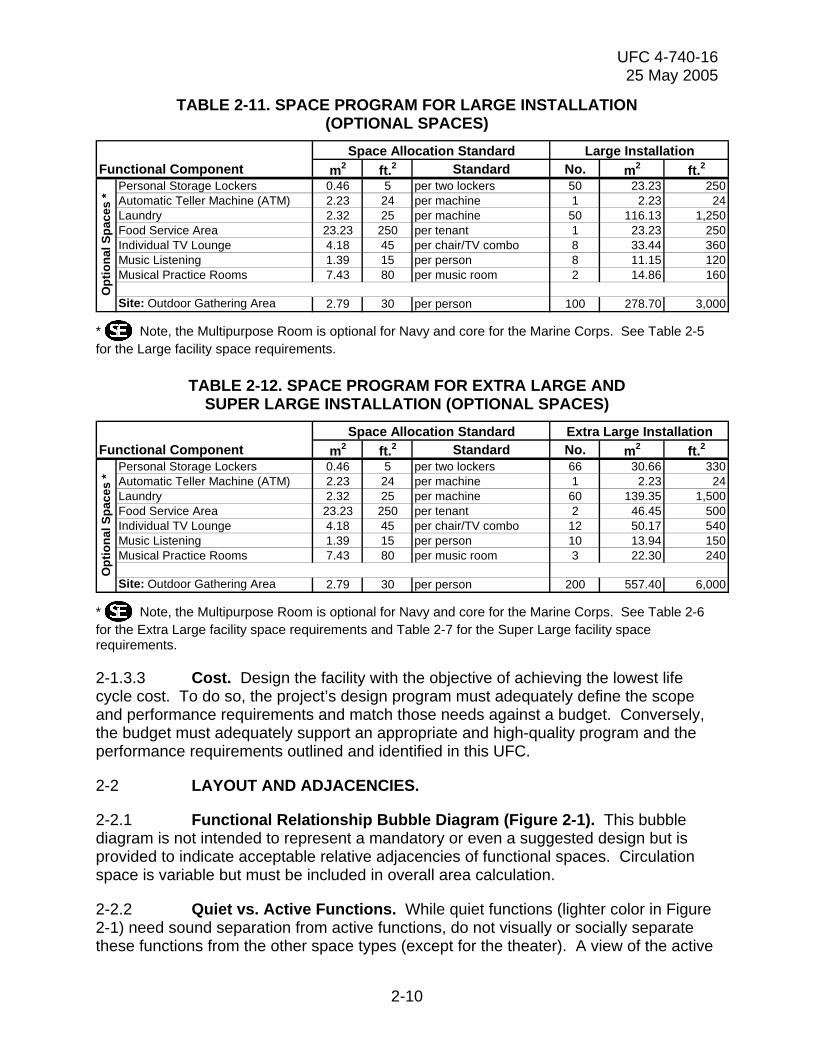
TABLE 2-11. SPACE PROGRAM FOR LARGE INSTALLATION (OPTIONAL SPACES)
0.0929Functional Component m2 ft.2 Standard No. m2 ft.2
Personal Storage Lockers 0.46 5 per two lockers 50 23.23 250Automatic Teller Machine (ATM) 2.23 24 per machine 1 2.23 24Laundry 2.32 25 per machine 50 116.13 1,250Food Service Area 23.23 250 per tenant 1 23.23 250Individual TV Lounge 4.18 45 per chair/TV combo 8 33.44 360Music Listening 1.39 15 per person 8 11.15 120Musical Practice Rooms 7.43 80 per music room 2 14.86 160
Site: Outdoor Gathering Area 2.79 30 per person 100 278.70 3,000
Space Allocation Standard Large Installation
Opt
iona
l Spa
ces
*
* Note, the Multipurpose Room is optional for Navy and core for the Marine Corps. See Table 2-5 for the Large facility space requirements.
TABLE 2-12. SPACE PROGRAM FOR EXTRA LARGE AND SUPER LARGE INSTALLATION (OPTIONAL SPACES)
0.0929Functional Component m2 ft.2 Standard No. m2 ft.2
Personal Storage Lockers 0.46 5 per two lockers 66 30.66 330Automatic Teller Machine (ATM) 2.23 24 per machine 1 2.23 24Laundry 2.32 25 per machine 60 139.35 1,500Food Service Area 23.23 250 per tenant 2 46.45 500Individual TV Lounge 4.18 45 per chair/TV combo 12 50.17 540Music Listening 1.39 15 per person 10 13.94 150Musical Practice Rooms 7.43 80 per music room 3 22.30 240
Site: Outdoor Gathering Area 2.79 30 per person 200 557.40 6,000
Extra Large InstallationSpace Allocation Standard
Opt
iona
l Spa
ces
*
* Note, the Multipurpose Room is optional for Navy and core for the Marine Corps. See Table 2-6 for the Extra Large facility space requirements and Table 2-7 for the Super Large facility space requirements.
2-1.3.3 Cost. Design the facility with the objective of achieving the lowest life cycle cost. To do so, the project’s design program must adequately define the scope and performance requirements and match those needs against a budget. Conversely, the budget must adequately support an appropriate and high-quality program and the performance requirements outlined and identified in this UFC.
2-2 LAYOUT AND ADJACENCIES.
2-2.1 Functional Relationship Bubble Diagram (Figure 2-1). This bubble diagram is not intended to represent a mandatory or even a suggested design but is provided to indicate acceptable relative adjacencies of functional spaces. Circulation space is variable but must be included in overall area calculation.
2-2.2 Quiet vs. Active Functions. While quiet functions (lighter color in Figure 2-1) need sound separation from active functions, do not visually or socially separate these functions from the other space types (except for the theater). A view of the active
2-10

UFC 4-740-16 25 May 2005
and more group-orientated functions from the quiet areas is critical to maintain a sense of social interaction.
FIGURE 2-1. FUNCTIONAL RELATIONSHIP BUBBLE DIAGRAM
Note: “phone” indicates a dedicated pay phone room. See Table 3-18 for more information on pay phones.
2-2.2.1 Space Assessment. See the Functional Data Sheets in paragraph 3-1 for additional information on the space types and their relationships to each other.
2-3 ALTERATIONS TO EXISTING FACILITIES.
2-3.1 Regulatory Authorities. The authorities are contained in OPNAVINST 11010.20F and NAVFACINST 11010.45D. Prior to planning alterations to an existing facility to convert it to an MRC, the activity should consult the following: Navy: NPC (Pers 656D/659) and Marine Corps: MCCS HQ (MRS/MRD)
2-3.2 Other Considerations. Consider the site of the existing facility and its limitations with regard to the MRC's needs. Only consider permanent facilities for conversion to a MRC. Exceptions may be made for other buildings that are in excellent condition, subject to the location determinants in paragraph 2-1.3. Consider adaptability to the intent of the building program. For instance, can the building accommodate a ground-floor facility with space and grading requirements for the mini theater? Does it
2-11

UFC 4-740-16 25 May 2005
have site space for the outdoor deck/patio area and patron parking? Whether planning a conversion, alteration or new construction, ATFP requirements must be taken into account (see paragraph 2-9).
2-3.3 Codes. Also make note of the Assembly nature of this function and its impact on construction type classification, fire protection, etc. For information regarding DoD use of codes, refer to UFC 1-200-01, UFC 3-600-01 and UFC 3-420-01.
2-4 EXTERIOR DESIGN. In general, the building’s image, theme, and fixtures must be consistent with the programs offered. The building design should reflect the local geographical and cultural environment. The building’s interior and exterior are presented as a recreational, not a warfare, facility. The building and site should provide a visually attractive and welcoming appearance with ample parking, and signs giving directions to the site. Avoid a hangar- or warehouse-like industrial appearance.
Provide only one, main patron entrance to facilitate security ID check and operational control. Other entrances/exits should be securable (see paragraph 2-6.4.1 for information on alarm systems). Equip the main entrance with an attractive, clearly located, illuminated sign that provides an inviting advertisement.
2-4.1 Structure. This building is most efficient as a single-story structure. Consider sloping the slab in the mini theater towards the screen wall if possible.
2-4.2 Exterior Finishes. The color, texture, and design should be consistent with the programs offered and the local environment and be appropriate for the building type. The exterior design should coordinate with the local Base Exterior Architectural Plan (BEAP), if available.
2-5 INTERIOR DESIGN. Construction and finishes (walls, floor, ceiling) should support the image and theme of the facility and be consistent with the programs offered. The interior design should offer the same interest, excitement, and professionalism that can be found in commercial facilities geared towards 17- to 25-year-old patrons.
Finishes should take into account the intended uses and be appropriately durable. For more information on finishes in specific areas, see the tables in Chapter 3.
2-6 SERVICES. See paragraph 2-10 for information on sustainable design and energy consumption.
2-6.1 Plumbing. Design domestic hot and cold water, sanitary and storm drainage, propane, fuel oil, or natural gas systems to meet the requirements of local installation standards and UFC 3-420-01.
2-6.2 Heating, Ventilating, and Air Conditioning (HVAC). Design the HVAC system to comply with the requirements of the most current edition of the International Mechanical Code. Use MIL-HDBK 1003/3 and ITG FY98-01 as supplemental guidance until it is replaced.
2-12

UFC 4-740-16 25 May 2005
2-6.3 Fire Protection. Design fire protection and life safety to comply with UFC 3-600-01. Power to the "acoustic" rooms (e.g. Music Practice Room, Music Listening, Individual TV Room) need to have the power interrupted to the equipment when the fire alarm system is activated.
2-6.4 Electrical. Provide electric service and distribution equipment, wiring receptacles and grounding, interior and exterior lighting and control, emergency lighting, telephone, communication systems, fire alarm, and intrusion systems in accordance with NEC and the latest installation design requirements. See the latest edition of Electric Current Abroad to determine voltages and cycles in overseas locations. Service grounding system and all wiring methods must meet the current NFPA 70 requirements. All service equipment must be Underwriters Laboratories (UL) listed. Alternately, published proof from an approved independent testing laboratory may be provided.
2-6.4.1 Communications. Facility-wide (computer room, offices, and customer service area) Internet service must be high-speed (T1 recommended). Standard phone line dial-up service is not acceptable. Additionally, consider special communications needs for the game room and mini theater such as cable television connections.
For larger or two- (or more) story facilities, the U.S. Marine Corps requires a two-way Intercom system throughout the facility. The system must allow music and have individual room controls. The Navy only requires a public address system. See Tables 3-2 and 3-4 for more information.
2-6.4.2 Alarm System. Consider providing an alarm system for intrusion detection to protect equipment and assets. Provisions for an alarm system must be justified during the planning/programming process.
2-6.4.3 Closed Circuit Television (CCTV). Consider providing a CCTV system. Provisions for a CCTV system must be justified during the planning/programming process. Service requirements vary on CCTV systems. Note the following criteria:
2-6.4.3.1 Navy. Provide conduit (minimum 19 mm (.75 in.)) and cabling to accommodate camera coverage in primary user spaces and accommodate controls and monitors located at the Customer Service Area and staff offices. The conduit will accommodate government-furnished/government-installed, locally-funded video equipment. This may require outlets higher in the ceilings, walls or both. Provide electrical service adjacent to anticipated location of cameras and monitors. Navy facilities must also accommodate the Navy and Marine Corps Intranet (NMCI); refer to UFC 3-580-10.
2-6.4.3.2 Marine Corps. Provide the entire CCTV system including cameras, monitors, conduit, cabling, power, and junction boxes for CCTV system. Provide camera coverage in primary user spaces, with controls and monitors located at the Customer Service Area and staff offices.
2-13

UFC 4-740-16 25 May 2005
2-7 SITE WORK.
2-7.1 Landscaping. Landscaping should reflect the programs offered and the local geographical environment. The plant selection should be easy to maintain and enhance the visual quality of the facility in all seasons. Native species are preferred. Do not use poisonous plants.
2-7.2 Site Lighting. Ensure that parking areas and the compound have adequate lighting for safety and security measures. See UFC 3-530-01.
2-7.3 Outdoor Activities. If space permits, consider providing the optional outdoor gathering area. See Table 3-17 for more information on this space.
2-8 BARRIER FREE DESIGN REQUIREMENTS. Design MRCs to be barrier-free and accessible in compliance with the Architectural Barriers Act (Public Law 90-480) of 1968, http://www.access-board.gov/ufas/ufas-html/ufas.htm - ABA. Provide barrier free design requirements in accordance with the Uniform Federal Accessibility Standards (UFAS), published as Federal Standard (FED-STD)-795, http://www.access-board.gov/ufas/ufas-html/ufas.htm, and 28 CFR Part 36, the Americans With Disabilities Act Accessibility Guidelines for Buildings and Facilities (ADAAG), http://www.access-board.gov/adaag/html/adaag.htm. When these two documents conflict, the one with the greatest accessibility requirement governs.
2-9 ANTITERRORISM REQUIREMENTS. The design must comply with the requirements of UFC 4-010-01.
2-10 SUSTAINABLE DESIGN. Use an integrated approach to the planning and design of MRCs. Consider sustainable strategies and features such as site selection and siting, energy conserving building envelope technologies, energy efficient lighting, occupant sensing controls, variable frequency drives for motors and exhaust fans, and high efficiency HVAC systems to achieve this goal. Incorporate renewable energy principles such as day-lighting, passive and active solar heating, natural ventilation, and photo-voltaics where they are life cycle cost effective. Follow the direction of NAVFAC Instruction 9830.1.
2-10.1 The United States Green Building Council (USGBC) LEED Green Building Rating System. Use the USGBC LEED Green Building Rating System to measure the sustainability of the completed project. It can also be used during planning and design as a source of green building strategies. LEED addresses sustainable sites, water efficiency, energy and atmosphere, materials and resources, and indoor environmental quality. It can be downloaded from USGBC at http://www.usgbc.org/programs/index.htm.
2-10.2 Energy Conservation. Follow the guidance in UFC 3-400-01 to achieve energy conserving designs.
2-10.3 EPA List of Affirmative Procurement Guideline Items. When specifying products that are included in EPA’s list of affirmative procurement guideline
2-14

UFC 4-740-16 25 May 2005
items, include the requirement for these products to meet or exceed the recycled material content standards established by EPA. The list of products and their corresponding recycled content requirements are found at www.epa.gov/cpg/products. Listed products likely to be used in MRCs include building insulation, carpet and cushion, cement and concrete, latex paint, floor tiles, patio blocks, restroom dividers, and structural fiberboard.
2-10.4 Whole Building Design Guide. The “Whole Building Design Guide” www.wbdg.org further explains the environmental issues related to building materials and provides technical guidance on green building material selection.
2-10.5 DoD Energy Budget. Design of new facilities must ensure that building energy consumption does not exceed the DoD energy budget figures.
2-15

UFC 4-740-16 25 May 2005
CHAPTER 3
FUNCTIONAL CRITERIA
3-1 FUNCTIONAL DATA SHEETS. Tables 3-1 through 3-20 are the Functional Data Sheets that present a description and all the functional criteria for each space within the facility.
TABLE 3-1. LOBBY/ENTRANCE Description/ Usage
The Lobby serves as the entrance to the facility and should be recognizable from the outside and be close to the base bus stop and patron parking. The lobby should lead directly into the game room by passing the Customer Service Area. ID checks will be required. Card access readers may be used for the ID checks. An air lock is recommended. May be used as an assembly point and waiting area for local bus stop.
Min. Ceiling Ht. 2.74 m (9 ft.) minimum. Finishes Walls. Painted gypsum wallboard. Consider the use of wall covering or wood where
budget and practical considerations allow. Floor. Stone or tile. Walk-off mat/area at the entrance door. Ceiling. Painted gypsum wallboard or specialty ceiling. Plumbing Wall mounted water fountain. HVAC 20 C (68 F) minimum, 26 C (78 F) maximum Fire Protection Building system. Power Provide one convenience outlet for general cleaning. If optional ATM machine is
provided, provide dedicated power. Lighting 540 Lux (50 ft. candles) Communication CCTV. None required.
CATV/Internal Video. None required. PA/Audio. Provide a speaker. Telephone. None required. Data. None required. Security. None required.
Casework None required. Furnishings Fixtures & Equipment (FF&E)
Cigarette Urn located at exterior entrance for disposal of smoking items. (Note that a designated smoking area must be at least 15.25 m (50 ft.) from the building.) Provide bench seating.
Special Requirements
If provided, place the optional ATM machine in the lobby/entrance area. Provide an exterior Marquis Sign and posted sign at the entrance with the hours of operation. The main exterior door must be lockable.
3-1

UFC 4-740-16 25 May 2005
TABLE 3-2. CUSTOMER SERVICE AREA/CONTROL
Description/ Usage
Space will provide a variety of customer services such as direct customer interface, POS, check-out equipment for various activities, control all audio and visual programs, tape machines, answer telephone and respond to inquiries, store tapes and rental equipment, and monitor and visually control access of entire facility. In smaller facilities, the hardware server may be located here.
Min. Ceiling Ht. 2.74 m (9 ft.) minimum. Finishes Walls. Painted gypsum wallboard kept to a minimum Floor. Carpet, VCT, and ceramic tile w/ vinyl base. Ceiling. Painted gypsum wallboard and/or specialty ceiling. Plumbing None required. HVAC 20 C (68 F) minimum, 26 C (78 F) maximum Fire Protection Building system. Power Provide power for all equipment. Perform a power requirement survey as this area’s
power requirements are extremely site and locale specific. Lighting 540 Lux (50 ft. candles). General ambient lighting. Consider decorative and task
lighting. Communication CCTV. May be required to monitor
CATV/Internal Video. Controls for TV Lounge and Mini Theatre. PA/Audio. Music and PA controls. Provide a speaker. Marine Corps requires an Intercom system to facilitate paging and response between this area and the offices. Telephone. Provide one line per two POS and fax. Provide one additional general-purpose phone line. Data. Provide one high-speed line per POS and fax. Provide additional lines, as needed, for associated hardware (e.g. RecTrac, LAN/WAN, and Internet connections). Security. None required.
Casework Provide a 610 mm (24 in.) deep counter with built-in cabinets. Provide file drawers and storage drawers with a minimum of two lockable for each POS. The counter should be dual height for standing transactions and seated office functions.
Furnishings Fixtures & Equipment (FF&E)
Desktop computer for administrative functions and for the operation of entertainment equipment. TV Lounge and Mini Theatre equipment. Chairs and stools. Tape storage cabinet. Computer racks.
Special Requirements
In extra small, small, and possibly medium facilities, the computer control space may be located at this counter. Consider the acoustics of this area as this is in a busy, noisy space.
3-2

UFC 4-740-16 25 May 2005
TABLE 3-3. SERVER ROOM
Description/ Usage
In larger facilities, the location of all the servers necessary to operate the Computer Room. Provide direct access to Computer Room.
Min. Ceiling Ht. 2.44 m (8 ft.) minimum. Finishes Walls. Painted gypsum wallboard. Floor. Anti-static, non-conductive vinyl tile w/ vinyl or rubber base. Ceiling. None required. Cable tray. Plumbing None required. HVAC 20 C (68 F) minimum, 26 C (78 F) maximum with 24/7 operation. Fire Protection Building system. Power Provide dedicated, grounded, convenience outlets for each server and monitor.
Provide power for UPS system and one additional power outlet for cleaning and maintenance.
Lighting Low level, non-glare task lighting as necessary. Communication CCTV. None required.
CATV/Internal Video. None required. PA/Audio. Provide a speaker. Telephone. Backboard for facility. Provide one line. Data. Provide high-speed (T1 recommended) line to serve facility. Security. Extend partitions from finished floor to underside of structure above. Seal around all penetrations. Lockable entrance/exit door.
Casework Standing countertop for monitors. Furnishings Fixtures & Equipment (FF&E)
Computer racks, UPS system, and stools.
Special Requirements
Plywood backing over gypsum wallboard for telephone backboards and UPS system.
3-3

UFC 4-740-16 25 May 2005
TABLE 3-4. COMPUTER ROOM
Description/ Usage
This space is for the general use of base-owned computers. The computers will be used for a wide range of activities such as browsing the Internet, emailing, and the printing, faxing, and copying of documents. The functional operation of this room may change depending on the size of the facility. In smaller facilities, some of the functions will be shared, monitored, and located at the Control Desk. While in larger facilities, these same functions may be located in the Computer Room itself. The Control Desk houses the printers, fax machines, copiers, and scanners. Provide direct access to Server Room.
Min. Ceiling Ht. 2.44 m (8 ft.) minimum Finishes Walls. Painted gypsum wallboard. Floor. Anti-static VCT or Carpet with vinyl wall base. Ceiling. ACP Plumbing None required. HVAC 20 C (68 F) minimum, 26 C (78 F) maximum with 24/7 operation. Fire Protection Building system. Power As necessary to support all the equipment in this room. Locations of outlets should be
specific to the layout of the room and may include recessed, floor-mounted junction boxes.
Lighting 540 Lux (50 ft. candles) general ambient lighting. Provide fixtures designed for use in computer environments.
Communication CCTV. None required. CATV/Internal Video. None required. PA/Audio. Provide one speaker. Telephone. Provide one telephone line per fax machine. No phone lines required. Data. Provide one line for each computer and additional lines for copiers, scanners, and fax machines. Security. None required.
Casework None required. Furnishings Fixtures & Equipment (FF&E)
Tables and chairs. Computers, fax machines, copiers, scanners, and other related computer equipment.
Special Requirements
In smaller facilities where the staff functions are located at the Control Desk, visual access to the Computer Room from the Control Desk is essential. Staffing ratios goals are: 1 staff helper/20 computers. Machine ratio goals are: 1 printer and fax machine/10 computers. Provide 1 scanner.
3-4

UFC 4-740-16 25 May 2005
TABLE 3-5. GAME ROOM
Description/ Usage
This space is the heart of the facility and, along with the mini theater; acts as the identity of the MRC. This room is the hub of activity. Besides housing the gaming activities, this room will serve as the ante-room (waiting room or overflow space) for the mini theater and TV lounge. Other functions, such as the computer room and the snack/vending area should open directly to this space. Some tables and chairs associated with the snack/vending area may be located within the game room. The game room should also have direct access to the optional outdoor gathering area.
Min. Ceiling Ht. 2.74 m (9 ft.) minimum with 3.05 m (10 ft.) preferable. Minimum 3.05 m (10 ft.) over pool tables.
Finishes Walls. Painted gypsum wallboard. Wallcoverings or wood panels may be used should budget allow.
Floor. Carpet, carpet tile, or VCT. Ceiling. ACP Plumbing None required. HVAC 20 C (68 F) minimum, 26 C (78 F) maximum Fire Protection Building system. Power Provide convenience outlets for all games. Coordinate location of outlets to avoid
tripping hazards. Consider floor boxes where necessary. Provide additional outlets per code.
Lighting 540 Lux (50 ft. candles) or lower for general ambient light. Provide accent lighting and focused lighting over pool tables, ping pong tables, foosball, etc.
Communication CCTV. Consider a camera to focus on coin and bill changer. CATV/Internal Video. Wall and/or ceiling mounted TV screens. PA/Audio. Provide speakers for adequate coverage of room. Telephone. None required. Data. None required. Security. None required.
Casework Drink rails at perimeter of room. Furnishings Fixtures & Equipment (FF&E)
No special requirements other than the games.
Special Requirements
Provide tamper resistant coin and bill changer. Large doors at delivery entrance for table and game replacement.
3-5
UFC 4-740-16 25 May 2005
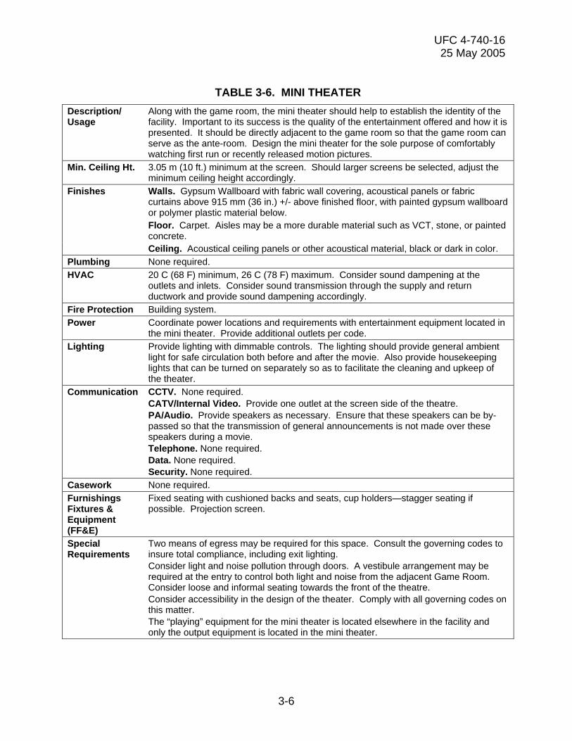
TABLE 3-6. MINI THEATER
Description/ Usage
Along with the game room, the mini theater should help to establish the identity of the facility. Important to its success is the quality of the entertainment offered and how it is presented. It should be directly adjacent to the game room so that the game room can serve as the ante-room. Design the mini theater for the sole purpose of comfortably watching first run or recently released motion pictures.
Min. Ceiling Ht. 3.05 m (10 ft.) minimum at the screen. Should larger screens be selected, adjust the minimum ceiling height accordingly.
Finishes Walls. Gypsum Wallboard with fabric wall covering, acoustical panels or fabric curtains above 915 mm (36 in.) +/- above finished floor, with painted gypsum wallboard or polymer plastic material below.
Floor. Carpet. Aisles may be a more durable material such as VCT, stone, or painted concrete.
Ceiling. Acoustical ceiling panels or other acoustical material, black or dark in color. Plumbing None required. HVAC 20 C (68 F) minimum, 26 C (78 F) maximum. Consider sound dampening at the
outlets and inlets. Consider sound transmission through the supply and return ductwork and provide sound dampening accordingly.
Fire Protection Building system. Power Coordinate power locations and requirements with entertainment equipment located in
the mini theater. Provide additional outlets per code. Lighting Provide lighting with dimmable controls. The lighting should provide general ambient
light for safe circulation both before and after the movie. Also provide housekeeping lights that can be turned on separately so as to facilitate the cleaning and upkeep of the theater.
Communication CCTV. None required. CATV/Internal Video. Provide one outlet at the screen side of the theatre. PA/Audio. Provide speakers as necessary. Ensure that these speakers can be by-passed so that the transmission of general announcements is not made over these speakers during a movie. Telephone. None required. Data. None required. Security. None required.
Casework None required. Furnishings Fixtures & Equipment (FF&E)
Fixed seating with cushioned backs and seats, cup holders—stagger seating if possible. Projection screen.
Special Requirements
Two means of egress may be required for this space. Consult the governing codes to insure total compliance, including exit lighting. Consider light and noise pollution through doors. A vestibule arrangement may be required at the entry to control both light and noise from the adjacent Game Room. Consider loose and informal seating towards the front of the theatre. Consider accessibility in the design of the theater. Comply with all governing codes on this matter. The “playing” equipment for the mini theater is located elsewhere in the facility and only the output equipment is located in the mini theater.
3-6

UFC 4-740-16 25 May 2005
TABLE 3-7. TV LOUNGE
Description/ Usage
The TV lounge is the “living room” of the facility. It should be comfortable and informal and be easily accessible to the game room. It is for group viewing of television, cable and broadcast events on a single large screen TV with a home theater sound system. Other TVs may be located in this room but should not distract from the focus of the large screen TV. The TV lounge may be open to the game room.
Min. Ceiling Ht. 2.74 m (9 ft.) minimum. Finishes Walls. Painted gypsum wallboard. Wall coverings or wood panels may be used
should budget allow. Floor. Carpet. Ceiling. Acoustical ceiling panels or gypsum wallboard. Plumbing N/A. HVAC 20 C (68 F) minimum, 26 C (78 F) maximum. Fire Protection Building system. Power Provide power for each TV and additional outlets per code. Lighting Provide dimmable lighting. Communication CCTV. None required.
CATV/Internal Video. Provide one outlet for each TV. PA/Audio. Provide necessary quantity of speakers for adequate coverage. Telephone. None required. Data. None required. Security. None required.
Casework None required. Furnishings Fixtures & Equipment (FF&E)
Comfortable chairs, sofas and end tables. Consider floor and table lamps to help create a living room environment.
Special Requirements
Consider needs for the home theater sound system.
3-7

UFC 4-740-16 25 May 2005
TABLE 3-8. SNACK/VENDING
Description/ Usage
Directly adjacent to the game room, this space should provide for simple vending of food and beverages. A seating area should accompany this space that could spill out into the game room. This area is not the food service/coffee bar but should work in conjunction with that optional space, if provided (See Table 3-13).
Min. Ceiling Ht. 2.44 m (8 ft) minimum. Finishes Walls. Painted gypsum wallboard. Consider vinyl wall covering. Floor. VCT with vinyl wall base. Ceiling. ACP. Consider washable panels. Plumbing Countertop sink with hot and cold water supply. Floor drain. HVAC 20 C (68 F) minimum, 26 C (78 F) maximum. Fire Protection Building system. Power Provide dedicated outlets for the vending machines and countertop height
convenience outlets for microwave. Lighting 540 Lux (50 ft. candles) general ambient lighting. Consider accent fixtures and lighting
to provide special ambience. Communication CCTV. None required.
CATV/Internal Video. None required. PA/Audio. Provide one speaker. Telephone. None required. Data. None required. Security. None required.
Casework Countertop with base and wall cabinets for storage of napkins, etc. Drink rail.
Furnishings Fixtures & Equipment (FF&E)
Under cabinet or counter microwave. Vending machines. Tables and chairs/stools.
Special Requirements
Refrigeration may be required for those centers which provide alcohol/beverage service.
3-8

UFC 4-740-16 25 May 2005
TABLE 3-9. FOOD SERVICE AREA
Description/ Usage
This optional space is provided to support the center with brand name retailers or equivalent. The space provided should be capable of supporting national vendors that provide a broad range of food and services. This area should be directly associated with the snack/vending area. Separate seating should not be provided for individual vendors and should be part of the seating included with snack/vending area. Seating should be carefully reviewed to insure that all food-associated spaces are properly supported. The equipment and final design of the space may be vendor specific and provided as part of the facility budget. This approach should be determined at the time of design and in consultation with potential vendors.
Min. Ceiling Ht. 2.44 m (8 ft) minimum. Finishes Walls. Painted gypsum wallboard. Floor. VCT with vinyl wall base. Ceiling. ACP. Consider washable panels. Plumbing As required to accommodate the specific vendor. HVAC 20 C (68 F) minimum, 26 C (78 F) maximum. Kitchen exhaust may be required to
accommodate a specific vendor. Fire Protection Building system. A hood suppression system may be required for specific cooking
equipment. If required, design this system in accordance with UFC 3-600-01. Power As required to accommodate the specific vendor. Lighting As required to accommodate the specific vendor. Communication CCTV. None required.
CATV/Internal Video. None required. PA/Audio. Provide one speaker. Telephone. Specific vendors may require a telephone outlet for a POS station and another outlet for general business use. Data. Specific vendors may require a data outlet for a POS station and another outlet for general business use. Security. Specific vendors may require a roll-up security gate to partition their serving line from the remainder of the facility during those times which the food service vendor is closed.
Casework As required to accommodate the specific vendor. Furnishings Fixtures & Equipment (FF&E)
As required to accommodate the specific vendor.
Special Requirements
As required to accommodate the specific vendor.
3-9

UFC 4-740-16 25 May 2005
TABLE 3-10. LIBRARY/QUIET ROOM
Description/ Usage
Quiet and comfortable area for studying, writing letters or reading books, newspapers, or magazines. This room should have visual access to the game room allowing patrons an opportunity to feel part of the activities while maintaining a noise level conducive to reading. Personal laptop computers may be used throughout the space. This space is not the Base Library.
Min. Ceiling Ht. 2.44 m (8 ft.) minimum. Finishes Walls. Painted gypsum wallboard. Floor. Carpet with vinyl wall base. Ceiling. ACP Plumbing None required HVAC 20 C (68 F) minimum, 26 C (78 F) maximum. Fire Protection Building system. Power Provide convenience outlets for cleaning. Provide additional outlets for the use of
hand held machines. Provide convenience outlets near tables for use with laptop computers.
Lighting 540 Lux (50 ft. candles) general ambient lighting. Provide task lighting at table/desks. Communication CCTV. None required.
CATV/Internal Video. None required. PA/Audio. Provide one speaker. Telephone. None required. Data. None required. Security. None required.
Casework Bookshelves may be provided as casework in lieu of FF&E. Furnishings Fixtures & Equipment (FF&E)
Tables and chairs for writing and studying with task lighting. Consider reclining type chairs, sofas, and end tables for an informal reading area. Floor and table lamps. Bookshelves, magazine and newspaper racks.
Special Requirements
Provide acoustical separation from the game room and other active functions. Provide adequate shade control to all windows.
3-10
UFC 4-740-16 25 May 2005
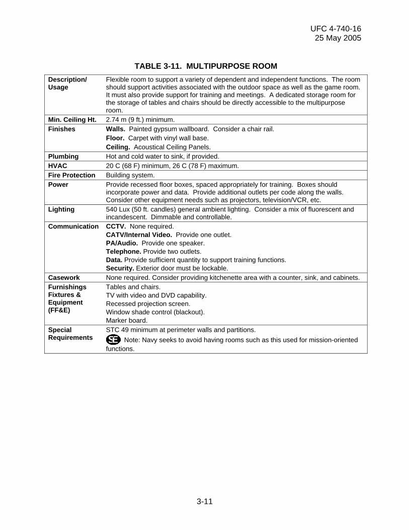
TABLE 3-11. MULTIPURPOSE ROOM
Description/ Usage
Flexible room to support a variety of dependent and independent functions. The room should support activities associated with the outdoor space as well as the game room. It must also provide support for training and meetings. A dedicated storage room for the storage of tables and chairs should be directly accessible to the multipurpose room.
Min. Ceiling Ht. 2.74 m (9 ft.) minimum. Finishes Walls. Painted gypsum wallboard. Consider a chair rail. Floor. Carpet with vinyl wall base. Ceiling. Acoustical Ceiling Panels. Plumbing Hot and cold water to sink, if provided. HVAC 20 C (68 F) minimum, 26 C (78 F) maximum. Fire Protection Building system. Power Provide recessed floor boxes, spaced appropriately for training. Boxes should
incorporate power and data. Provide additional outlets per code along the walls. Consider other equipment needs such as projectors, television/VCR, etc.
Lighting 540 Lux (50 ft. candles) general ambient lighting. Consider a mix of fluorescent and incandescent. Dimmable and controllable.
Communication CCTV. None required. CATV/Internal Video. Provide one outlet. PA/Audio. Provide one speaker. Telephone. Provide two outlets. Data. Provide sufficient quantity to support training functions. Security. Exterior door must be lockable.
Casework None required. Consider providing kitchenette area with a counter, sink, and cabinets. Furnishings Fixtures & Equipment (FF&E)
Tables and chairs. TV with video and DVD capability. Recessed projection screen. Window shade control (blackout). Marker board.
Special Requirements
STC 49 minimum at perimeter walls and partitions. Note: Navy seeks to avoid having rooms such as this used for mission-oriented
functions.
3-11

UFC 4-740-16 25 May 2005
TABLE 3-12. PERSONAL STORAGE LOCKERS
Description/ Usage
This optional space is for the short term storage of personal goods such as coats, backpacks, etc.
Min. Ceiling Ht. 2.44 m (8 ft.) minimum. Finishes Walls. Painted gypsum wallboard. Floor. VCT with vinyl wall base. Ceiling. ACP Plumbing None required. HVAC 20 C (68 F) minimum, 26 (78 F) maximum. Fire Protection Building system. Power None required. Lighting 540 Lux (50 ft. candles) general ambient lighting. Communication CCTV. None required.
CATV/Internal Video. None required. PA/Audio. Provide one speaker. Telephone. None required. Data. None required. Security. Provide security camera that can view lockers.
Casework None required. Furnishings Fixtures & Equipment (FF&E)
Lockers: plastic, pad-lockable, 305 mm wide by 455 mm deep (12 in. x 18 in.), double-tier, with coat hook.
Special Requirements
None required.
3-12

UFC 4-740-16 25 May 2005
TABLE 3-13. LAUNDRY
Description/ Usage
This optional Laundromat provides a practical function for the facility. It should be directly accessible to the game room. Also consider direct access to the outside. The facility may remain open 24/7 or at times when the MRC is closed—must be capable of being locked-off from the remainder of the facility.
Min. Ceiling Ht. 2.74 m (9 ft.) minimum. Finishes Walls. Painted water-resistant gypsum wallboard. Floor. VCT. Ceiling. Acoustical Ceiling Panels. Consider washable and humidity resistant panels.
Gypsum wallboard ceiling can also be used. Plumbing Hot and cold water to each of the washing machines and one laundry sink. Floor
drains. Provide recessed plumbing cabinets for each utility connection to the machines.
HVAC 20 C (68 F) minimum, 26 C (78 F) maximum. Provide separate vents for the dryers. Provide adequate dehumidification as part of the building systems.
Fire Protection Building system. Power Provide power to each washer and dryer. Provide power for the bill change machine,
laundry product vending machines, and TVs. Provide power near the folding area for irons. Do not provide any other additional outlets other than those required and identified above.
Lighting 540 Lux (50 ft. candles) general ambient lighting. Provide occupancy sensors. Communication CCTV. Consider a camera positioned to monitor the bill change machine.
CATV/Internal Video. Provide one outlet for each TV. PA/Audio. Provide one speaker. Telephone. Provide outlets for one or two optional pay phones. Data. None required. Security. Lockable doors to the exterior and interior.
Casework Display case/board for advertising local events and attraction. Furnishings Fixtures & Equipment (FF&E)
Wall or ceiling mounted TVs. Folding tables and hanging racks or clothes lines. Chairs. Extra large, high capacity washers and dryers—provide machines on a ratio of three dryers/two washers. Additional heavy-duty washer and dryer machines. Laundry product vending machines. Tamper resistant coin/bill change machine. Pay phones and associated cabinets.
Special Requirements
Provide lockable exterior double doors for machine access and maintenance. Provide lockable (from MRC) interior door for access to MRC facility. Provide easy access to rear of dryers to allow easy maintenance and cleaning of vents.
3-13

UFC 4-740-16 25 May 2005
TABLE 3-14. INDIVIDUAL TV ROOM
Description/ Usage
This room is for the use of individuals wishing to privately watch TV. The chairs provided for this space are typically custom-designed with an integrated television screen and sound system. The arrangement of chairs is such that individual, private viewing is possible.
Min. Ceiling Ht. 2.44 m (8 ft) minimum. Finishes Walls. Painted gypsum wallboard. Floor. Carpet or VCT with vinyl wall base. Ceiling. ACP Plumbing None required HVAC 20 C (68 F) minimum, 26 C (78 F) maximum. Fire Protection Building system. Power Provide recessed junction boxes at chair locations for power and communications. Lighting Provide dimmable lighting. Should be subdued and relatively dark. Avoid screen
glare. Communication CCTV. None required.
CATV/Internal Video. Provide one line per chair. Integrate with power. PA/Audio. Provide one speaker. Telephone. None required. Data. None required. Security. None required.
Casework None required. Furnishings Fixtures & Equipment (FF&E)
Custom recliners—one chair per one TV. The recliner should have 19 in. (483 mm) TV, VCR, and DVD player.
Special Requirements
Provide adequate light control at windows.
3-14

UFC 4-740-16 25 May 2005
TABLE 3-15. MUSIC LISTENING
Description/ Usage
Optional area or room to allow patrons to listen to music with a headset from a hand-held music player. Provide comfortable lounge chairs and visual access to the active areas of facility.
Min. Ceiling Ht. 2.44 m (8 ft.) minimum. Finishes Walls. Painted gypsum wallboard. Floor. Carpet w/ vinyl wall base. Ceiling. ACP Plumbing None required. HVAC 20 C (68 F) minimum, 26 C (78 F) maximum. Fire Protection Building system. Power Provide outlets per code. Lighting 540 Lux (50 ft. candles) general dimmable ambient lighting. Consider floor and table
mounted lights. Communication CCTV. None required.
CATV/Internal Video. None required. PA/Audio. Provide one speaker. Telephone. None required. Data. None required. Security. None required.
Casework None required. Furnishings Fixtures & Equipment (FF&E)
Easy chairs and sofas. End tables and coffee tables. Table and floor lamps.
Special Requirements
Consider acoustics.
3-15

UFC 4-740-16 25 May 2005
TABLE 3-16. MUSIC PRACTICE ROOM(S)
Description/ Usage
Small, individual rooms to allow one, two, or maybe three patrons to practice music on a variety of instruments. The rooms should provide privacy for the users—visual access to the rest of the facility is not necessary. The room sizes may vary to allow for individual practice or group practice.
Min. Ceiling Ht. 2.44 m (8 ft.) minimum. Finishes Walls. Painted gypsum wallboard. Partitions should be floor to underside of deck
above. Floor. VCT or Carpet with vinyl wall base. Ceiling. ACP Plumbing None required. HVAC 20 C (68 F) minimum, 26 C (78 F) maximum. This can be a very active room and may
require additional ventilation. Fire Protection Building system. Power Provide two quad. convenience outlets, each on a dedicated circuit. Lighting 540 Lux (50 ft. candles) general ambient lighting. Communication CCTV. None required.
CATV/Internal Video. None required. PA/Audio. Provide one speaker. Telephone. None required. Data. None required. Security. None required.
Casework None required. Furnishings Fixtures & Equipment (FF&E)
None required.
Special Requirements
Consider an acoustical vestibule to these rooms as either an individual vestibule for each room or an acoustically secure corridor.
3-16

UFC 4-740-16 25 May 2005
TABLE 3-17. OUTDOOR GATHERING AREA
Description/ Usage
This optional exterior space is designed to work in conjunction with the interior functions of the game room and multipurpose room or to function independently of the interior. This area will host parties, games, and other outside activities sponsored by the base. Consider co-locating other recreation functions in or near the outdoor gathering area (e.g. basketball, horseshoes, and sand volleyball).
Min. Ceiling Ht. Not Applicable. Finishes Walls. Not Applicable. Floor. Brick or concrete pavers, wood, or exposed concrete for hardscape areas.
Grass, mulch, or sand for softscape areas. Ceiling. Not Applicable. Plumbing Keyed, tamper-resistant hose bibb. HVAC None required. Fire Protection Building system. Power Provide several exterior grade convenience outlets. Consider power requirements for
a stage. Lighting Ground level, low lumen 55 Lux (5 ft. candles) decorative lighting. Consider lighting
paths also. Communication CCTV. None required.
CATV/Internal Video. None required. PA/Audio. Provide several speakers for adequate coverage. Speakers to be outdoor type. Consider outdoor noise levels when spacing speakers. Telephone. None required. Data. None required. Security. Provide fence around entire perimeter. If budget allows, provide a decorative fence. Provide a decorative gate that is alarmed and lockable. Access to the outdoor gathering area must be from the interior spaces of the MRC except on occasions when the exterior gate can be staffed.
Casework None required. Furnishings Fixtures & Equipment (FF&E)
Grills (gas or propane) Benches Waste receptacles (must meet ATFP criteria).
Special Requirements
Consider providing shade structures, if budget allows. Consider landscaping appropriate to an outdoor recreation area.
3-17

UFC 4-740-16 25 May 2005
TABLE 3-18. PAY TELEPHONES
Description/ Usage
This area houses pay telephones for use by patrons of the facility. The telephones may be used for quick local calls or long distance calls to friends and family. These phones may be centralized in one area of the facility or spread throughout—most likely near or adjacent to the game room. For larger facilities (Large, Extra Large, and Super Large), consider providing a separate room or area near the quiet functions in addition to phones spread throughout the game room.
Min. Ceiling Ht. 2.44 m (8 ft) minimum. Finishes Walls. Painted gypsum wallboard. Floor. VCT with vinyl wall base. Ceiling. ACP Plumbing None required. HVAC 20 C (68 F) minimum, 26 C (78 F) maximum. Fire Protection Building system. Power Provide outlets per code. Lighting 540 Lux (50 ft. candles) general ambient lighting. Communication CCTV. None required.
CATV/Internal Video. None required. PA/Audio. Provide one speaker. Telephone. None required. Data. None required. Security. None required.
Casework Tables (credenza-like) custom-designed for telephone use. Furnishings Fixtures & Equipment (FF&E)
Chairs.
Special Requirements
Surfaces directly in front of caller should be highly absorptive to prevent voice deflection. Speech privacy is very important. Also provide one duty phone (on-base line) near the Customer Service Area.
3-18

UFC 4-740-16 25 May 2005
TABLE 3-19. STAFF OFFICES
Description/ Usage:
The Program Manager has a private office; other staff in open office plan with systems furniture. Larger facilities may have two private offices—one for the overall program manager and one for the individual center manager. Offices are used for planning, developing, organizing, supervising, implementing, promoting, and evaluating facility operations. The offices should free from frequent distraction—this is not a customer service area. However, the office area should have a view of the customer service area. The offices should have a professional appearance and a sense of work place.
Min. Ceiling Ht.: 2.74 m (9 ft.) minimum. Finishes: Walls. Painted gypsum wall board. Floor. Carpet w/ vinyl base Ceiling. ACP Plumbing: None required. HVAC 20 C (68 F) minimum, 26 c (78 F) maximum Fire Protection Building system. Power Provide outlets per code and one quad outlet per staff. Provide additional outlets as
necessary to operate shared equipment such as printers, fax, etc. Lighting Lighting levels 860 – 1,290 Lux (80 – 120 ft. candles). General ambient fixtures. Communication CCTV. None required.
CATV/Internal Video: None required. PA/Audio: Provide a speaker. Telephone. Provide one line per staff plus one additional line for fax and copier. Data. Provide one line per staff plus one line for each printer, copier, scanner, etc. Security. None required.
Casework: Consider providing work counter space and office supply storage. Furnishings Fixtures & Equipment (FF&E):
Program Manager's office provided with private office furniture. General office space provided with systems furniture with chairs for each workstation and guest chairs for each desk. Consider File Cabinets. Note: The office layout and furnishings should take into account the size of all office equipment to be installed (i.e., desks, computer equipment, copiers, intercom controls, safes, etc.). For Marine Corps facilities, office equipment also includes CCTV controls and monitors. The Navy does not support CCTV control/monitor installation in offices.
Special Requirements:
Should have view of Customer Service Area. If possible, provide exterior windows. Will have multiple safes. Provide a secured, small storage closet.
3-19

UFC 4-740-16 25 May 2005
TABLE 3-20. TOILETS (MALE AND FEMALE)
Description/ Usage:
Convenience facilities for patrons and staff.
Min. Ceiling Ht.: 2.44 m (8 ft.) minimum. Finishes: Walls. Ceramic tile on all wet walls to a minimum of 1830 mm (6 ft.) above the finish
floor. Gypsum wallboard with enameled paint at all other locations. Floor. Non-slip ceramic tile with integral ceramic tile coved base. Ceiling. Painted gypsum wallboard. Plumbing: Floor drains, hot and cold domestic water, venting, and other accessories per code.
Plumbing equipment: Water closets and urinals with flush valves, lavatories with faucets. Hose bibb with removable key under lavatory counter.
HVAC 20 C (68 F) minimum, 26 C (78 F) maximum. Provide dedicated, 100% exhaust directly to the outside.
Fire Protection Building system. Power Provide outlets per code. Lighting 540 Lux (50 ft. candles) ambient lighting. Provide additional down light in front of
mirror. Communication CCTV. None permitted.
CATV/Internal Video: None required. PA/Audio: Provide a speaker. Telephone. None required. Data. None required. Security. None required.
Casework: Solid-surface countertop with either underhung or integral sink. Solid composite toilet and urinal partitions. Toilet accessories: toilet paper dispensers, toilet seat cover dispensers, paper towel dispenser with integrated trash receptacle, robe hooks, sanitary napkin dispensers, grab bars, and soap dispensers. Mirror.
Furnishings Fixtures & Equipment (FF&E):
None required.
Special Requirements:
STC 42 minimum at all perimeter walls and partitions. Ensure accessibility for the physically challenged. Door closer and mop plate required on entrance door. Provide a janitor’s closet with a floor mop sink and drain, storage shelves, and hooks for mops and brooms.
Note: For Marine Corps facilities, provide 80% male toilets and 20% female toilets. For Navy facilities, male to female ratios are determined by the local installation.
3-20
UFC 4-740-16 25 May 2005
APPENDIX A
REFERENCES
GOVERNMENT PUBLICATIONS: 1. Department of Defense (DOD)
Unified Facilities Criteria Program
http://dod.wbdg.org/ UFC 1-200-01, Design: General Building Requirements
UFC 3-400-01, Design: Energy
Conservation UFC 3-420-01, Design: Plumbing
Systems UFC 3-580-10, Design: Navy and
Marine Corps Intranet (NMCI) Standard Construction Practices
UFC 3-600-01 Design: Fire Protection
Engineering for Facilities UFC 4-010-01, DoD Minimum
Antiterrorism Standards for Buildings 2. Naval Facilities Engineering Command Engineering Innovation and Criteria P-80, Facility Planning Office 6506 Hampton Blvd NAVFACINST 11010.45D, Norfolk, VA 23508 Comprehensive Regional Planning
Instruction http://www.navfac.navy.mil/ MIL-HDBK 1003/3, Heating, Ventilating,
Air Conditioning, and Dehumidifying Systems
ITG FY98-01, International Mechanical
Code (IMC)
A-1

UFC 4-740-16 25 May 2005
3. Navy Personnel Command PERS-654 Liberty Program Accreditation MWR 5720 Integrity Drive Standards and Metrics Document (July Millington, TN 38055 2001) http://www.mwr.navy.mil/ 4. SECNAV/OPNAV Directives Control Office N09B15 OPNAVINST 11010.20F, Facilities Washington Navy yard, Bldg. 36 Projects Manual 720 Kennon Street, SE Rm 203 Washington Navy Yard, DC 20374 http://neds.nebt.daps.mil/usndirs.htm 5. Directorate of Defense Information, U.S. Marine Corps Room 2E765, The Pentegon Semper Fit MCO P1700.29 Washington, DC 20301-1400 (703) 697-5131 SMP MCO P1700.36 http://www.hqmc.usmc.mil/pubs.nsf 6. U.S. Department of Commerce International Trade Administration Electric Current Abroad (1998) 14th & Constitution Ave, NW Washington, DC 20230 (202) 482-3917 http://www.ita.doc.gov/ 7. National Institute of Building Sciences 1090 Vermont Avenue, NW Whole Building Design Guide Suite 700 www.wbdg.org Washington, DC 20005-4905 (202) 289-7800 http://www.nibs.org/ 8. National Archives and Records Administration 700 Pennsylvania Avenue, NW Architectural Barriers Act (Public Law Washington, DC 20408 90-480) of 1968, (866) 325-7208 http://www.access-board.gov/ufas/ufas-html/ufas.htm - ABA.
A-2

UFC 4-740-16 25 May 2005
A-3
http://www.access-board.gov/ufas/ Uniform Federal Accessibility Standards ufas-html/ufas.htm (UFAS), published as Federal Standard
(FED-STD)-795, http://www.access-board.gov/adaag/ 28 CFR Part 36, the Americans With html/adaag.htm Disabilities Act Accessibility Guidelines
for Buildings and Facilities (ADAAG), NON-GOVERNMENT PUBLICATIONS:
1. International Code Council Headquarters International Mechanical Code 5203 Leesburg Pike Suite 600 Falls Church, VA 22041 http://www.iccsafe.org/
2. National Fire Protection Association 1 Batterymarch Park NFPA 70 National Electric Code (2002) Quincy, Massachusetts 02169-7471 (617) 770-3000 http://www.nfpa.org/
3. The United States Green Building Council US Green Building Council LEED Green Building Rating System 1015 18th Street, NW, Suite 805 Washington, DC 20036 http://www.usgbc.org/