Embed Size (px)
Citation preview
1
Experimental Sounding Rocket Association
Unexploded Ordnance Hybrid Rocket
Team 38 Project Technical Report for the 2018 IREC
Nicholas Christopher, Tom Cojocar, Jacob Deery, Miranda Daly, Colin Farrow, Doris Jiang, Shirley Kong, Hilbert
Li, Robin Liu, Emily Ma, Mikayla Marczak, Alexandra Mihaila, Aaron Morrison, David Ng, Adam Paul, Vithusan
Rajkumar, and Edward Yang1
University of Waterloo, Waterloo, Ontario, N2L 3G1, Canada
Unexploded Ordnance (UXO) is a hybrid rocket developed by Waterloo Rocketry for entry
in the 10000 ft apogee with Student Researched & Developed (SRAD) hybrid/liquid
propulsion system category at the 2018 Intercollegiate Rocket Engineering Competition. The
UXO launch vehicle is powered by the Kismet engine, a nitrous oxide/hydroxyl-terminated
polybutadiene SRAD hybrid engine, and features a deployable payload system designed for a
3U CubeSat. The primary objective of UXO is to attain an apogee of between 8000 ft and
12000 ft and achieve a non-hazardous descent, while the objective of the payload is to achieve
successful deployment at apogee, followed by video documentation of payload descent and
proper functionality of data acquisition electronics. In support of these objectives, the team
has developed robust ground support equipment systems for safe and efficient management
of rocket pre-launch activities and launch operations.
Nomenclature
AGL = Above Ground Level
ASL = Above Sea Level
CO2 = Carbon Dioxide
CONOPS = Mission Concept of Operations
COTS = Commercial Off-the-Shelf
DAQ = Data Acquisition
ESRA = Experimental Sounding Rocket Association
FOS = Factor of Safety
GSE = Ground Support Equipment
GPS = Global Positioning System
HTPB = Hydroxyl-terminated polybutadiene
I2C = Inter-Integrated Circuit
ID = Inner Diameter
IMU = Inertial Measurement Unit
IREC = Intercollegiate Rocket Engineering Competition
LiPo = Lithium polymer
NO = Normally Open
NOS = Nitrous Oxide
OD = Outer Diameter
PCB = Printed Circuit Board
PPE = Personal Protective Equipment
RLCS = Remote Launch Control System
SAC = Spaceport America Cup
SF = Static Fire
SPI = Serial Peripheral Interface
SRAD = Student Researched and Developed
UXO = Unexploded Ordnance
1 All authors team members of Waterloo Rocketry
2
Experimental Sounding Rocket Association
I. Introduction
ATERLOO Rocketry is an engineering student team representing the University of Waterloo, from Waterloo,
Ontario, Canada. The team will be competing in the 2018 Intercollegiate Rocket Engineering Competition
(IREC) at the 2nd Annual Spaceport America Cup (SAC) with the Unexploded Ordnance (UXO) rocket, which is
entered in the 10000 ft apogee with Student Researched & Developed (SRAD) hybrid/liquid propulsion system
category. The primary mission objective is to launch UXO to an apogee between 8000 ft and 12000 ft AGL, followed
by successful recovery system operation and a non-hazardous descent. A secondary objective is successful operation
of the payload module, although this objective is not essential for mission success.
The team comprises approximately 20 undergraduate students studying Mechanical, Mechatronics, Electrical,
Computer, Chemical, Civil, Nanotechnology, and Systems Design Engineering. The Team Lead is responsible for
overall project management and team direction, including overseeing all technical, administrative, and operational
activities necessary to achieve team objectives. Technical projects are led by Project Leads, who are chosen based on
past experience, skillset, and interest. Project Leads are responsible for coordinating and managing all aspects related
to their projects, leading the design, manufacture, and testing of their systems, and ensuring the successful integration
of their project with other vehicle and ground systems. Team members are welcome to work on any projects that
interest them, and project teams often have significant overlap and collaboration. Although one team member takes
on the role of Safety Captain and is responsible for development and maintenance of safety documentation and
procedures, safety is the responsibility of every team member and is always the team’s highest priority.
Team stakeholders include academic partners, advisors, sponsors, and team members. The team represents the
University of Waterloo and owes much to the institutions and resources that the University makes available to student
teams. The team’s advisors, both from within the University and from industry, are hugely helpful in sharing
knowledge and providing insight as the team continues to develop more complex and sophisticated systems. Team
sponsors are additional stakeholders, as they have provided significant material and financial support essential for the
team’s operation. Finally, the team’s most important stakeholders are the team members. The primary objective of the
team is to provide students with opportunities to engage in hands-on learning through practical engineering challenges.
Team growth and continuity is contingent on the team’s ability to maintain this atmosphere of learning and
collaboration while remaining competitive and improving year-to-year. Many past and present members have
dedicated significant time and effort to the team, and continued success is a recognition of this commitment.
II. System Architecture Overview
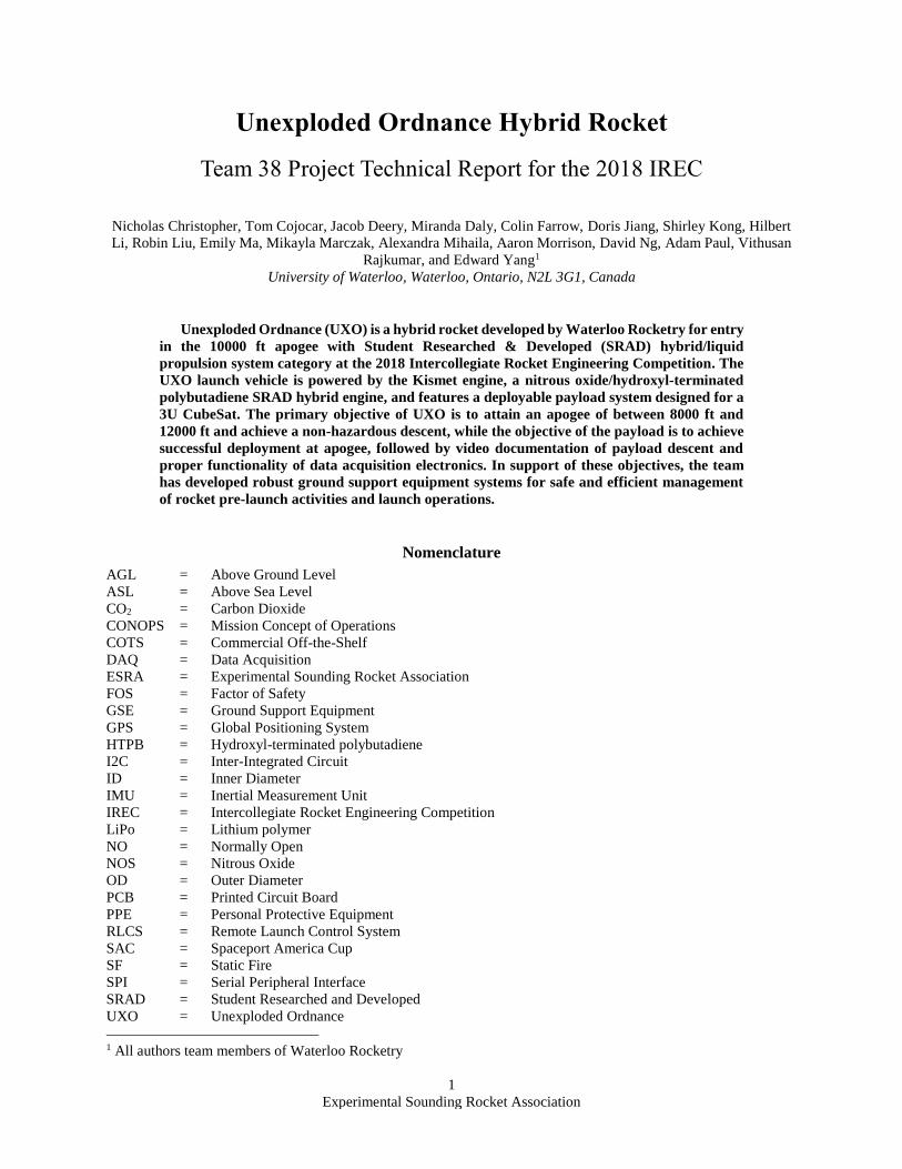
UXO is a hybrid rocket measuring 178” in length and 6” in diameter. The vehicle can be divided into three major
modules: the Kismet engine, the recovery system, and the payload. UXO was designed with modularity in mind; all
major sections are self-contained and separable. In addition to vehicle systems, the team has developed ground support
equipment (GSE) systems necessary for fill and launch operations. A full sectional view of UXO can be seen in Figure
1.
Figure 1. UXO sectional view. UXO is a modular design permitting rapid assembly and disassembly of individual
subsystems.Visible in this figure, from left to right: fin can, Kismet engine, recovery module, payload module, nose
cone.
A. Propulsion Subsystems
UXO uses the Kismet engine, an SRAD hybrid engine with liquid nitrous oxide (NOS) as the oxidizer and
hydroxyl-terminated polybutadiene (HTPB) as the fuel. A cross section of the engine is shown in Figure 2. Kismet
was initially designed to achieve a 30000 ft apogee; however, due to a low combustion efficiency (60%), the current
revision of the engine will carry the rocket to approximately 10000 ft. Almost all of the components of the engine are
manufactured by team members in the University of Waterloo’s student machine shop. No CNC work was done on
any of the engine components, in order to promote learning through hands-on manufacturing processes. All major
structural components of the engine, including the tanks and bulkheads, are made of 6061-T6 aluminium alloy. This
material was selected as it is relatively inexpensive, available in a variety of sizes and form factors, and easily
machineable.
W
3
Experimental Sounding Rocket Association
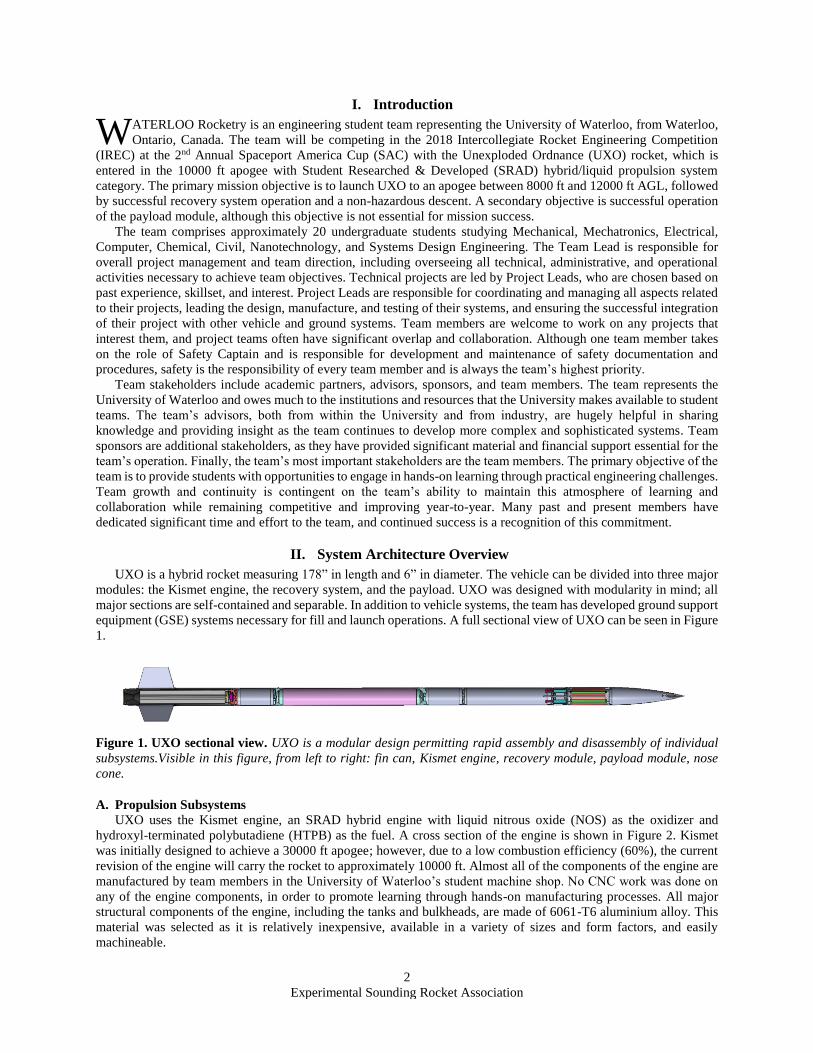
Figure 2. Kismet engine cross section. A sectional view of the Kismet engine, including detail of the vent valve
section, oxidizer tank, injector valve section, injector, combustion chamber, and nozzle. Exterior combustion chamber
airframe section and electronics assemblies are not shown.
1. Oxidizer Tank
The Kismet oxidizer tank has a 6” outer diameter (OD), 3/16” wall thickness, and is 48” long. The tank is sealed
on both ends by bulkheads with two Buna-N o-rings. The bulkhead are joined to the tube with twenty-four 1/4”-28
bolts arranged radially, which results in a minimum factor of safety of 2.4 in bearing failure of the tank. A static
structural finite element model was used to minimize the mass of the bulkheads, which resulted in the end wall
thickness of 3/8”. The tank has been successfully hydrostatically tested to a factor of safety (FOS) of 1.5 times the
maximum expected operating pressure of 1000 psi.
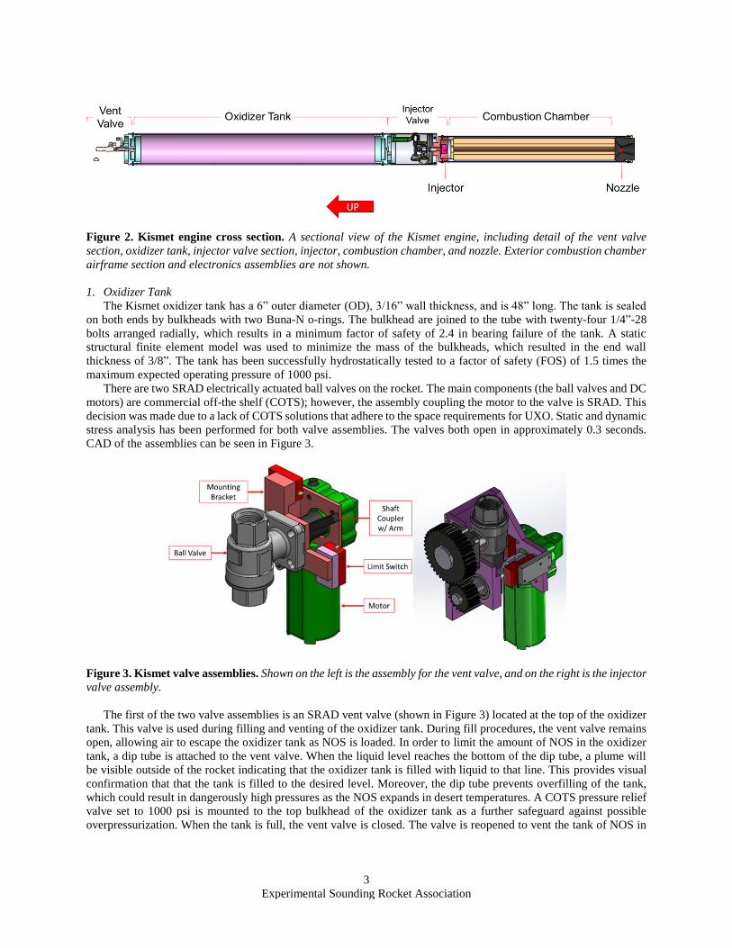
There are two SRAD electrically actuated ball valves on the rocket. The main components (the ball valves and DC
motors) are commercial off-the shelf (COTS); however, the assembly coupling the motor to the valve is SRAD. This
decision was made due to a lack of COTS solutions that adhere to the space requirements for UXO. Static and dynamic
stress analysis has been performed for both valve assemblies. The valves both open in approximately 0.3 seconds.
CAD of the assemblies can be seen in Figure 3.
Figure 3. Kismet valve assemblies. Shown on the left is the assembly for the vent valve, and on the right is the injector
valve assembly.
The first of the two valve assemblies is an SRAD vent valve (shown in Figure 3) located at the top of the oxidizer
tank. This valve is used during filling and venting of the oxidizer tank. During fill procedures, the vent valve remains
open, allowing air to escape the oxidizer tank as NOS is loaded. In order to limit the amount of NOS in the oxidizer
tank, a dip tube is attached to the vent valve. When the liquid level reaches the bottom of the dip tube, a plume will
be visible outside of the rocket indicating that the oxidizer tank is filled with liquid to that line. This provides visual
confirmation that that the tank is filled to the desired level. Moreover, the dip tube prevents overfilling of the tank,
which could result in dangerously high pressures as the NOS expands in desert temperatures. A COTS pressure relief
valve set to 1000 psi is mounted to the top bulkhead of the oxidizer tank as a further safeguard against possible
overpressurization. When the tank is full, the vent valve is closed. The valve is reopened to vent the tank of NOS in
4
Experimental Sounding Rocket Association
the event of an aborted launch attempt. Oxidizer is loaded into the tank through a port on the bottom bulkhead. This
port is connected to fill hoses via a quick disconnect mechanism and has an internal check valve.
The second valve assembly is mounted between the oxidizer tank and combustion chamber, above the injector. It
is opened after the primary ignition sequence is initiated, to allow flow of oxidizer into the combustion chamber. This
assembly has a gearset, which is used in order to align the center of the valve with the center of the rocket, thereby
reducing flow losses.
2. Combustion Chamber
The combustion chamber shell is a 1/8” thick, 5” OD cylinder. Both the top bulkhead and the nozzle are sealed
with two Buna-N o-rings. The combustion chamber is insulated with a 1/8” thick G10 fiberglass tube and sealed with
flame-resistant caulking on the top and bottom ends. The chamber has a FOS of 2.6 and has been hydrostatically tested
to 2.1 times the maximum expected operating pressure of 500 psi.
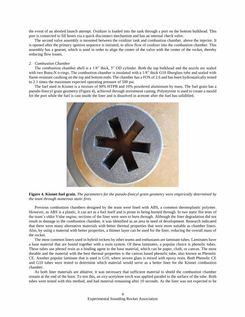
The fuel used in Kismet is a mixture of 90% HTPB and 10% powdered aluminium by mass. The fuel grain has a
pseudo-finocyl grain geometry (Figure 4), achieved through investment casting. Polystyrene is used to create a mould
for the port while the fuel is cast inside the liner and is dissolved in acetone after the fuel has solidified.
Figure 4. Kismet fuel grain. The parameters for the pseudo-finocyl grain geometry were empirically determined by
the team through numerous static fires.
Previous combustion chambers designed by the team were lined with ABS, a common thermoplastic polymer.
However, as ABS is a plastic, it can act as a fuel itself and is prone to being burned through. In two static fire tests of
the team’s older Vidar engine, sections of the liner were seen to burn through. Although the liner degradation did not
result in damage to the combustion chamber, it was identified as an area in need of development. Research indicated
that there were many alternative materials with better thermal properties that were more suitable as chamber liners.
Also, by using a material with better properties, a thinner layer can be used for the liner, reducing the overall mass of
the rocket.
The most common liners used in hybrid rockets by other teams and enthusiasts are laminate tubes. Laminates have
a base material that are bound together with a resin system. Of these laminates, a popular choice is phenolic tubes.
These tubes use phenol resin as a binding agent to the base material, which can be paper, cloth, or canvas. The most
durable and the material with the best thermal properties is the canvas based phenolic tube, also known as Phenolic
CE. Another popular laminate that is used is G10, where woven glass is mixed with epoxy resin. Both Phenolic CE
and G10 tubes were tested to determine which material would serve as a better liner for the Kismet combustion
chamber.
As both liner materials are ablative, it was necessary that sufficient material to shield the combustion chamber
remain at the end of the burn. To test this, an oxy-acetylene torch was applied parallel to the surface of the tube. Both
tubes were tested with this method, and had material remaining after 10 seconds. As the liner was not expected to be
5
Experimental Sounding Rocket Association
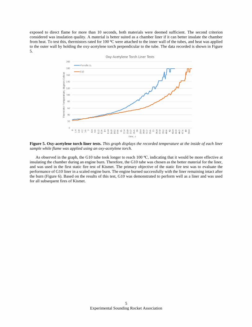
exposed to direct flame for more than 10 seconds, both materials were deemed sufficient. The second criterion
considered was insulation quality. A material is better suited as a chamber liner if it can better insulate the chamber
from heat. To test this, thermistors rated for 100 ⁰C were attached to the inner wall of the tubes, and heat was applied
to the outer wall by holding the oxy-acetylene torch perpendicular to the tube. The data recorded is shown in Figure
5.
Figure 5. Oxy-acetylene torch liner tests. This graph displays the recorded temperature at the inside of each liner
sample while flame was applied using an oxy-acetylene torch.
As observed in the graph, the G10 tube took longer to reach 100 ⁰C, indicating that it would be more effective at
insulating the chamber during an engine burn. Therefore, the G10 tube was chosen as the better material for the liner,
and was used in the first static fire test of Kismet. The primary objective of the static fire test was to evaluate the
performance of G10 liner in a scaled engine burn. The engine burned successfully with the liner remaining intact after
the burn (Figure 6). Based on the results of this test, G10 was demonstrated to perform well as a liner and was used
for all subsequent fires of Kismet.
6
Experimental Sounding Rocket Association
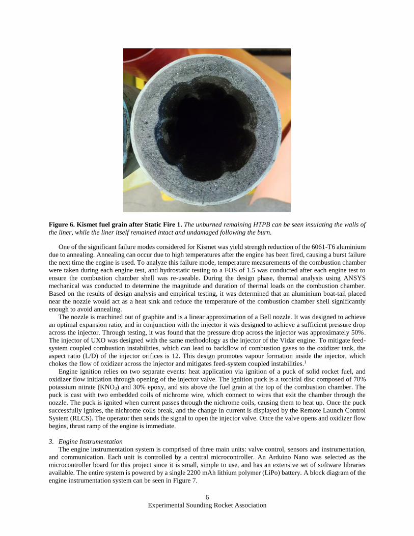
Figure 6. Kismet fuel grain after Static Fire 1. The unburned remaining HTPB can be seen insulating the walls of
the liner, while the liner itself remained intact and undamaged following the burn.
One of the significant failure modes considered for Kismet was yield strength reduction of the 6061-T6 aluminium
due to annealing. Annealing can occur due to high temperatures after the engine has been fired, causing a burst failure
the next time the engine is used. To analyze this failure mode, temperature measurements of the combustion chamber
were taken during each engine test, and hydrostatic testing to a FOS of 1.5 was conducted after each engine test to
ensure the combustion chamber shell was re-useable. During the design phase, thermal analysis using ANSYS
mechanical was conducted to determine the magnitude and duration of thermal loads on the combustion chamber.
Based on the results of design analysis and empirical testing, it was determined that an aluminium boat-tail placed
near the nozzle would act as a heat sink and reduce the temperature of the combustion chamber shell significantly
enough to avoid annealing.
The nozzle is machined out of graphite and is a linear approximation of a Bell nozzle. It was designed to achieve
an optimal expansion ratio, and in conjunction with the injector it was designed to achieve a sufficient pressure drop
across the injector. Through testing, it was found that the pressure drop across the injector was approximately 50%.
The injector of UXO was designed with the same methodology as the injector of the Vidar engine. To mitigate feed-
system coupled combustion instabilities, which can lead to backflow of combustion gases to the oxidizer tank, the
aspect ratio (L/D) of the injector orifices is 12. This design promotes vapour formation inside the injector, which
chokes the flow of oxidizer across the injector and mitigates feed-system coupled instabilities.1
Engine ignition relies on two separate events: heat application via ignition of a puck of solid rocket fuel, and
oxidizer flow initiation through opening of the injector valve. The ignition puck is a toroidal disc composed of 70%
potassium nitrate (KNO3) and 30% epoxy, and sits above the fuel grain at the top of the combustion chamber. The
puck is cast with two embedded coils of nichrome wire, which connect to wires that exit the chamber through the
nozzle. The puck is ignited when current passes through the nichrome coils, causing them to heat up. Once the puck
successfully ignites, the nichrome coils break, and the change in current is displayed by the Remote Launch Control
System (RLCS). The operator then sends the signal to open the injector valve. Once the valve opens and oxidizer flow
begins, thrust ramp of the engine is immediate.
3. Engine Instrumentation
The engine instrumentation system is comprised of three main units: valve control, sensors and instrumentation,
and communication. Each unit is controlled by a central microcontroller. An Arduino Nano was selected as the
microcontroller board for this project since it is small, simple to use, and has an extensive set of software libraries
available. The entire system is powered by a single 2200 mAh lithium polymer (LiPo) battery. A block diagram of the
engine instrumentation system can be seen in Figure 7.
7
Experimental Sounding Rocket Association
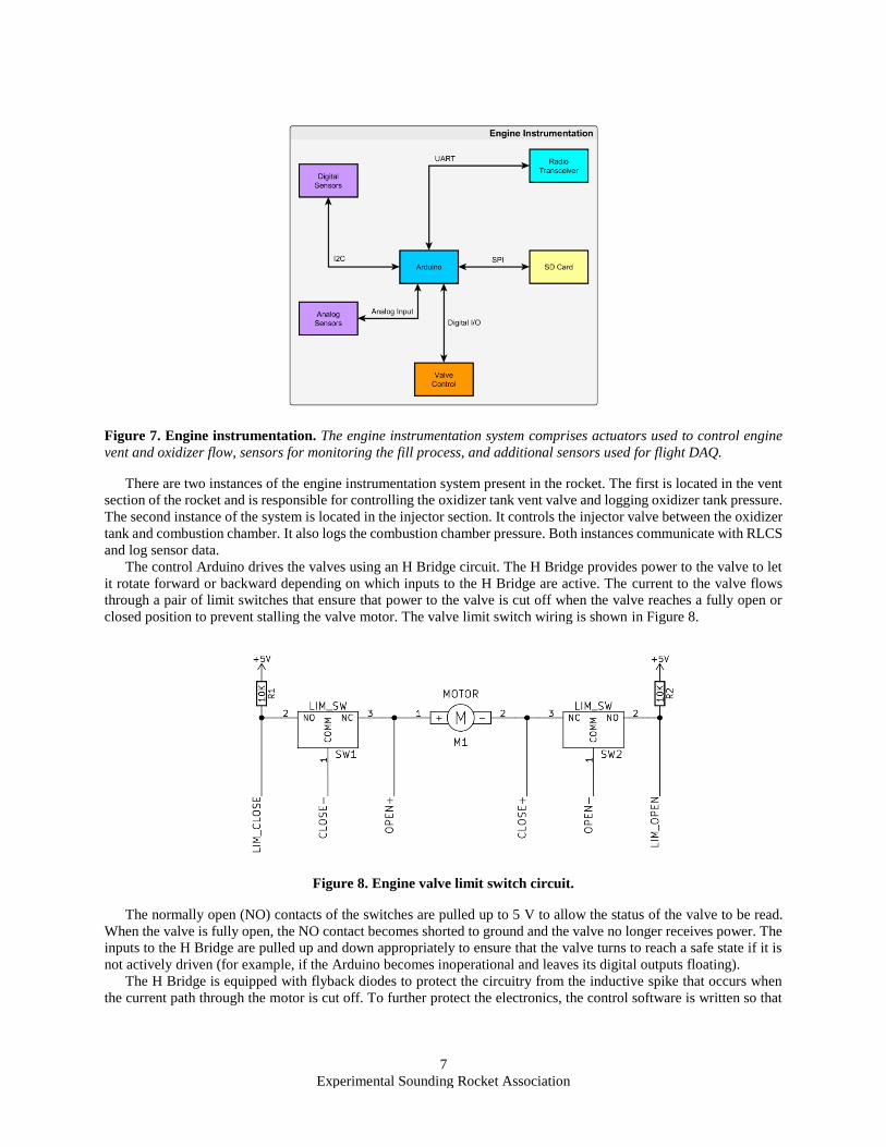
Figure 7. Engine instrumentation. The engine instrumentation system comprises actuators used to control engine
vent and oxidizer flow, sensors for monitoring the fill process, and additional sensors used for flight DAQ.
There are two instances of the engine instrumentation system present in the rocket. The first is located in the vent
section of the rocket and is responsible for controlling the oxidizer tank vent valve and logging oxidizer tank pressure.
The second instance of the system is located in the injector section. It controls the injector valve between the oxidizer
tank and combustion chamber. It also logs the combustion chamber pressure. Both instances communicate with RLCS
and log sensor data.
The control Arduino drives the valves using an H Bridge circuit. The H Bridge provides power to the valve to let
it rotate forward or backward depending on which inputs to the H Bridge are active. The current to the valve flows
through a pair of limit switches that ensure that power to the valve is cut off when the valve reaches a fully open or
closed position to prevent stalling the valve motor. The valve limit switch wiring is shown in Figure 8.
Figure 8. Engine valve limit switch circuit.
The normally open (NO) contacts of the switches are pulled up to 5 V to allow the status of the valve to be read.
When the valve is fully open, the NO contact becomes shorted to ground and the valve no longer receives power. The
inputs to the H Bridge are pulled up and down appropriately to ensure that the valve turns to reach a safe state if it is
not actively driven (for example, if the Arduino becomes inoperational and leaves its digital outputs floating).
The H Bridge is equipped with flyback diodes to protect the circuitry from the inductive spike that occurs when
the current path through the motor is cut off. To further protect the electronics, the control software is written so that
8
Experimental Sounding Rocket Association
transistors in series are not switched simultaneously. This prevents “shoot-through” conditions in which power and
ground briefly become shorted together.
The instrumentation portion of engine instrumentation records the following sensor data:
• Combustion chamber pressure
• Oxidizer tank pressure
• Pitch, roll, and yaw of the rocket
• Acceleration of the rocket
• Barometric pressure
• Ambient temperature
• Temperatures of various surfaces inside the rocket
These readings are continuously logged and saved to a microSD card.
A variety of gyroscopes, accelerometers, barometers, and magnetometers were considered for the system’s sensor
suite. The primary consideration was whether the selected sensors would be able to capture enough information to
construct a reasonable model of the rocket in flight. Ideally, the system would capture readings for altitude, velocity,
acceleration, and attitude independently so that the error of each measurement could be reduced by comparing it to
related measurements. Measuring velocity directly proved to be difficult since it required modifications to the
airframe. As such, the system measures altitude (derived from barometric pressure and temperature), acceleration, and
attitude. The system contains a barometric pressure sensor, an inertial measurement unit (IMU) containing an
accelerometer and gyroscope, and an independent gyroscope.
Once the parameters to be measured were established, sensors were selected according to cost, communication
mode, voltage level, and physical package. Sensors with analog outputs were avoided due to a shortage of analog
inputs on the Arduino. Instead, the selected sensors all communicate over a single I2C bus. While all the selected
sensors also have SPI capabilities, I2C was selected because it requires significantly fewer wires, which makes printed
circuit board routing much easier. All the selected digital sensors have compatible input voltage ranges and were wired
to run on a common voltage level of 3.0 V. The communication signals to and from the sensors pass through a
bidirectional shifting circuit to allow the Arduino and sensors to communicate without problems. Finally, each sensor
had to be available in a package that could reliably be soldered without industrial tooling.
B. Aero-structures Subsystems
The UXO airframe is constructed entirely from aluminium and fiberglass components. The recovery module,
payload module, and combustion chamber are all contained within fiberglass tubes joined with aluminium couplers,
while the oxidizer tank has a 6” OD and thus has no additional outer airframe section. The nose cone is a custom
fiberglass part, and the fins are constructed from aluminium.
1. Nose Cone
The main purpose of the nose cone is to reduce the form drag of the rocket while protecting the payload and
deployment systems. A tangent ogive nosecone with a 4:1 fineness ratio was selected as it minimized simulated drag
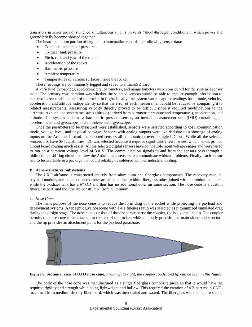
during the design stage. The nose cone consists of three separate parts: the coupler, the body, and the tip. The coupler
permits the nose cone to be attached to the rest of the rocket, while the body provides the main shape and structure
and the tip provides an attachment point for the payload parachute.
Figure 9. Sectional view of UXO nose cone. From left to right, the coupler, body, and tip can be seen in this figure.
The body of the nose cone was manufactured as a single fiberglass composite piece so that it would have the
required rigidity and strength while being lightweight and hollow. This required the creation of a 2-part mold CNC-
machined from medium-density fiberboard, which was then sealed and waxed. The fiberglass was then cut to shape,
9
Experimental Sounding Rocket Association
laid in the mold, and infused with resin before being vacuum bagged and cured. The final body was then trimmed and
sanded to remove any surface imperfections. The tip of the nose cone was machined from 6061-T6 aluminium alloy
and 303 stainless steel as it was infeasible to achieve the desired shape with the team’s layup process. The coupler
was also machined from 6061-T6 in order to attain the necessary strength and geometry required for integration with
the rest of the rocket airframe.
The completed nose cone body was tested by applying 68 kgf of compressive force along the longitudinal axis, to
simulate the aerodynamic forces during flight, which the nose cone withstood with no issues. The composite resin
system is capable of withstanding the temperatures achieved during launch and flight. A drop test was also conducted
on the nose cone tip to prove its durability. As a result, there are minimal concerns regarding the possibility of failure
of the nose cone.
2. Fins
UXO uses a fin can assembly of three through-the-wall trapezoidal fins welded to 6” OD, 13” long, 1/4” thick
cylindrical 6061-T6 stock. 6061-T6 was chosen as the material for the fin can components for its good weldability
and strength. The fins have a 12” root chord, an 8” tip chord, and a semispan of 7.25”. The semispan was constrained
to be less than 18” to avoid interference with the launch tower. The fins have a trapezoidal cross-section measuring
1/8” in thickness, with a 45 chamfer on the leading and trailing edge to decrease drag and induce a roll rate. In order
to validate that the chosen fin geometry was sufficient to ensure stable flight, simulation was conducted using
OpenRocket software with data taken from static engine testing. At liftoff, UXO will have a stability margin of
approximately 2.3 cal. This will slowly rise during the flight, reaching 4.5 cal at motor burnout. The rail departure
velocity is predicted to be 76 ft/s.
Structural failure of fins caused by aeroelastic flutter is a concern on rockets approaching transonic and supersonic
speeds because oscillations in the airflow can couple with the natural elastic properties of the fins to create a positive
feedback loop of increasing oscillations in the fins themselves. A fin flutter analysis was performed on the chosen fin
geometry by calculating the flutter velocity (the velocity above which the airflow will amplify rather than dampen
oscillations in the fin) and comparing it to UXO’s maximum predicted velocity. It was calculated that fin flutter would
begin to occur at 1763 ft/s, well above the maximum velocity of 688 ft/s predicted by simulation.
The three fins are joined to the can using all-around concave fillet welds. From an aerodynamics perspective,
concave fillet welds are preferable over bolted connections because they reduce interference drag by rounding out the
sharp angles at the attachment point between the can and the fins. The choice of thickness was influenced by concerns
about weld distortion along the fin can. The magnitude of warping in a part due to the thermal stresses created in the
welding process depends on many factors, and the thickness of the material being welded is one of them. The 1/4”
thickness of the can will reduce the amount of weld distortion, although weld distortion is difficult to quantify without
knowledge of the exact welding process.
C. Recovery Subsystems
The UXO recovery system is housed in two adjacent fiberglass tubes joined by aluminium couplers. The lower
tube houses UXO’s parachutes and recovery lines and is secured to the top of the oxidizer tank vent section with radial
bolts. The bottom coupler of the parachute section contains a plate into which an eyebolt is threaded. This eyebolt
serves as the primary mounting point for recovery lines. The upper tube houses electronics used for recovery
deployment and vehicle tracking. The two recovery sections are connected with mating aluminium couplers and
secured with three nylon rivets. These nylon rivets act as shear pins and allow the sections to separate during recovery
deployment.
UXO’s recovery system uses dual deployment events, deploying a drogue parachute 5 seconds after apogee and a
main parachute at 1500 ft AGL. A 5 second delay was selected for drogue deployment to ensure that this event does
not interfere with payload deployment. As the payload deployment event occurs at apogee, the 5 second delay
decreases the risk that any of the recovery lines will tangle. Drogue deployment is carried out using a carbon dioxide
(CO2) canister-based separation mechanism. A CO2 canister is mounted into an ejection cylinder that contains an steel
cylinder with a sharp point, a small amount of gunpowder, and an electric match. This cylinder is sealed with epoxy,
and the electric match is connected to the drogue output terminals of the altimeter. When the altimeter sends the drogue
signal, the electric match ignites, causing the gunpowder to detonate and shoot the steel cylinder forward into the CO2
canister. The sharp point of the cylinder punctures the canister, causing it to eject CO2 into the parachute section. The
increasing pressure inside this section applies a force to the mating recovery electronics coupler, causing the nylon
rivets to shear and separating the sections. As the electronics section is pushed away from the rest of the rocket, an
10
Experimental Sounding Rocket Association
attached line pulls the drogue parachute from the parachute section. The drogue parachute has a diameter of 37.5” and
slows UXO’s descent to a rate of 114 ft/s.
Prior to main parachute deployment, the parachute is secured by a two-ring release mechanism. The release
mechanism consists of two interlocking rings secured together by a nylon cord. The cord is secured within a
pyrotechnic cutter mechanism. This mechanism is similar to the CO2 ejection mechanism used for drogue deployment,
but uses the pointed cylinder to sever the nylon cord instead of puncture a CO2 cylinder. Like the drogue ejection
mechanism, the pyrotechnic cutter is actuated via electric match; this match is connected to the main output terminals
of the altimeter. At 1500 ft AGL, the electric match is detonated, causing the cord to sever and allowing the rings to
slip past one another. This allows the main parachute to be pulled from the airframe section by the drag force of the
drogue parachute. The main parachute was tested in a wind tunnel at various speeds to determine the drag coefficient.
Based on this experimentally determined drag coefficient, the size of the parachute was calculated for a ground hit
speed of 29 ft/s. The resulting parachute has a diameter of 142”.
UXO uses two COTS altimeters for recovery deployment. Two different altimeters, a PerfectFlite StratoLoggerCF
and a Featherweight Raven3, were selected in order to decrease the risk of common mode failures and increase the
reliability of the system. Each altimeter is powered by a 9 V battery and armed immediately prior to launch using a
magnetic switch actuated from outside of the rocket. Dual redundancy of the deployment system is achieved using
two altimeters, two CO2 ejectors, and two pyrotechnic cutters. Each altimeter is capable of independently triggering
each ejector and each cutter, and actuation of one ejector and one cutter is sufficient for deployment. This allows the
system to tolerate failure of an altimeter, an ejector, and a cutter, while still resulting in safe recovery.
D. Payload Subsystems
The function of the payload subsystem is to carry a camera and instrument package to an altitude of 10000 feet,
deploy it from the rocket, and recover it safely via parachute. The goal of the payload experiment is to evaluate the
performance of the deployment mechanism in order to promote future iteration and development of scientific
payloads.
The team elected to develop a deployable payload system this year in order to increase the variety of experiments
that can be flown in future years. The advantages that a deployable payload has for scientific experiments include
exposure to open air, increased time at high altitudes, clear line of sight to ground, and inability to damage launch
vehicle in event of experiment failure.
Due to time constraints and uncertainty about deployment system performance, the team did not believe it was
feasible or prudent to install a scientific payload in the CubeSat this year. Instead, a technology demonstration CubeSat
was developed, and the data collected from it will be used to design scientific payloads to be used with the deployment
system in future years.
In order to meet IREC minimum standards and qualify as a functional payload, the payload must:
• Weigh a minimum of 8.8 lb.
• Contain no more than 1/4 of the total payload mass as deadweight.
• Adhere to the CubeStat standard in a 3U form factor.
• Not contain any prohibited materials.
• Adhere to safety critical wiring standards for any recovery elements.
• Adhere to the “Payload Recovery” guidelines outlined in the design, test and evaluation guide.
• Adhere to the “Stored-Energy Devices” standard of the design, test and evaluation guide for our
deployment electronics.
• Have a tracking system on board for location following recovery.
Additional constraints on the payload design were determined by UXO architecture. The payload must:
• Fit in a 6” OD airframe section.
• Not interfere with the main UXO recovery system.
• Have the deployment system fail safe.
For the purposes of this section, “fail safe” deployment indicates that a deployment failure does not place the
rocket into an unsafe state; that is, if the payload does not successfully deploy, no components of the rocket are ejected
without recovery systems or exceed the maximum speed for safe recovery under main parachute.
The payload subsystem consists of three parts: the CubeSat, the deployment system, and the ground system. The
CubeSat is mounted in the deployer at the top of the rocket. At apogee, the deployer is triggered and releases the
CubeSat from the rocket, where it deploys a parachute and falls back to earth. The arming of the deployment system
11
Experimental Sounding Rocket Association
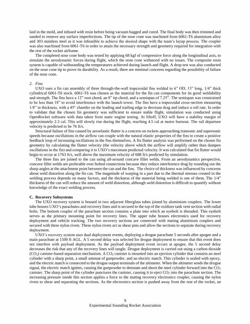
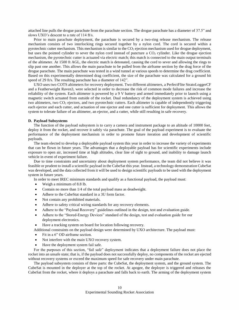
and collection of payload data is handled by a handheld transponder. A render of the complete system can be seen in
Figure 10, and a system block diagram for the payload electrical systems can be seen in Figure 11.
Figure 10. Render of complete payload system. The CubeSat can be seen at the left of the image. Also visible is the
deployment mount (center; airframe tube) and the nose cone.
Figure 11. Payload block diagram. The payload systems comprise a suite of on-rocket sensors and custom PCBs for
control and data acquisition, along with a handheld transponder for arming of the payload display of data.
1. CubeSat
The goal of the CubeSat is to demonstrate the safety and effectiveness of the deployment system in order to justify
development of scientific payloads for deployment. To accomplish this, various sensors are installed in the CubeSat.
These sensors are:
• Pressure sensor
• Temperature sensors
• Inertial Measurement Units (IMUs)
• GPS
• Ambient light sensor
The CubeSat sensor suite records data during the flight and logs recorded data to an SD card on the instrumentation
board. Data is also transmitted once per second to the ground. From this data, the position, altitude, vertical velocity,
deployment event characteristics, and landing characteristics can be determined. The CubeSat also contains a GoPro
HERO4 Black camera, which records video documentation of the payload’s deployment and recovery.
At the 2017 IREC, the team’s payload also featured a GoPro camera. Unfortunately, the camera overheated prior
to launch and no video footage of the flight was captured. It was theorized that this was a result of the transparent
acrylic tube used for the payload airframe, which behaved similarly to the glass walls of a greenhouse. As the airframe
for UXO’s payload would be non-transparent, overheating was not identified as a major concern. To ensure that the
camera could withstand ambient desert temperatures, thermal tests of the payload were conducted. The test procedure
consisted of heating the air around the CubeSat housing to 60 C and determining at what point the camera triggered
a thermal shutdown. It was determined that the camera would be able to withstand temperatures of up to 56 C, and
as such was suitable for use in the desert.
The altimeter used by the CubeSat is a PerfectFlite StratoLoggerCF. This altimeter was selected for its relatively
inexpensive cost, small footprint, low power requirements, and versatility.
12
Experimental Sounding Rocket Association
2. Deployment System
The CubeSat initially rests on the top coupler of the recovery electronics section and sits in between eight Delrin
rails. Prior to deployment, it is held in place by these rails and the top coupler of the deployment mount section. Above
the deployment mount is the nose cone, where the payload recovery system is stored. The deployment mount is
attached to the recovery electronics top coupler with three nylon rivets. To trigger payload deployment, the altimeter
stored on the CubeSat activates a CO2 deployment mechanism identical to the one used for UXO drogue deployment.
Once the deployment mount has separated from the main body of UXO, the CubeSat is unsupported and falls away
from the rest of the rocket. As it falls, the CubeSat pulls the payload parachute from the nose cone. The parachute
measures 47” in diameter and slows the CubeSat to a descent rate of 29 ft/s. It was determined that a redundant
deployment system was not necessary for CubeSat recovery, as a failed deployment does not place the rocket into an
unsafe state; the payload will simply remain attached to and be recovered with the rest of the rocket. UXO’s recovery
system is sized such that the rocket will descend at an acceptable rate even if the payload fails to deploy.
During the initial design phase, alternative solutions were considered for the physical deployment mechanism,
including the use of a powerful compression spring capable of exerting enough force to shear the nylon rivets. The
spring would be held in a locked position by a pyrotechnic bolt that could be sheared using a gunpowder charge to
allow the spring to release. This approach was not chosen for several reasons:
• Improper manufacturing of the pyrotechnic bolt could cause premature spring release
• The team was not confident in the ability to develop pyrotechnic bolts safely and reliably
• Compression of the spring for loading into the rocket could not be done in a safe manner
Overall, the team determined that the CO2 ejection system was more reliable and safer to develop and operate.
In order to test the full payload deployment system, the payload and deployment mount were assembled on a
testing rig. A vacuum pump was attached to the pressure equalization hole of the deployment mount and powered on,
causing the pressure inside of the deployment mount to decrease. As the StratoLoggerCF is a barometric altimeter,
this pressure drop registers as an increase in altitude. In order to simulate apogee, the vacuum pump was powered off,
allowing the pressure inside the deployment mount to rise. The StratoLoggerCF interprets this pressure change as a
change from increasing altitude to decreasing altitude, and therefore signals that apogee has occurred. All electronic
components functioned as intended and the deployment system was actuated successfully.
3. Ground System
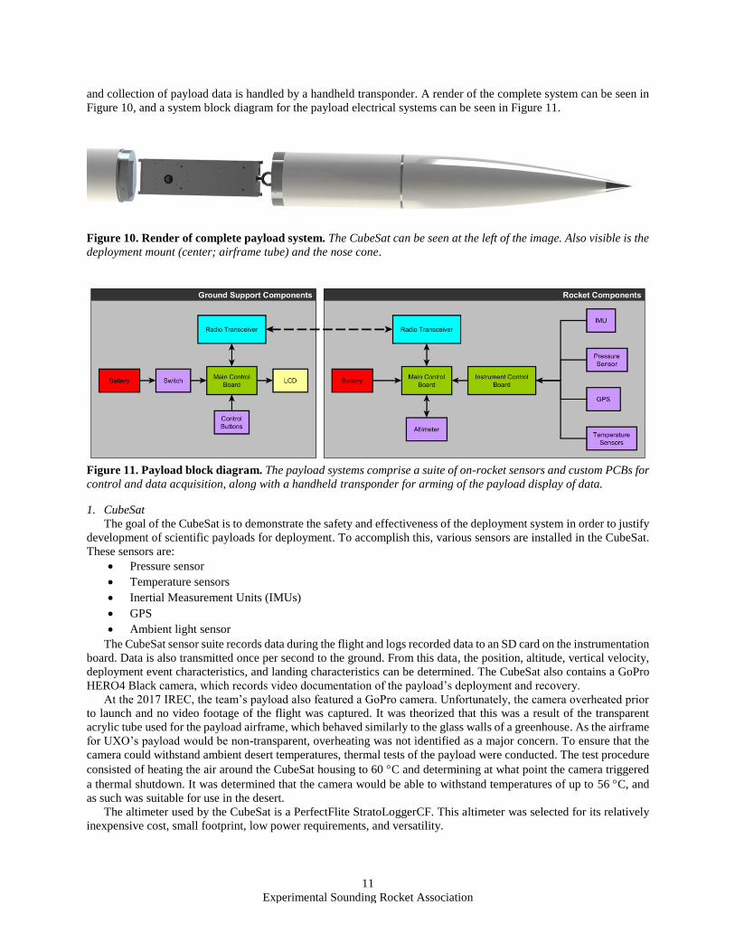
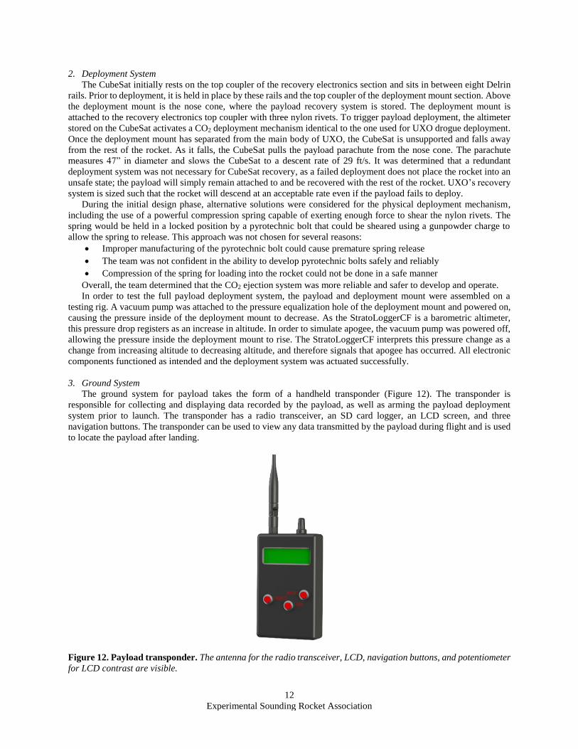
The ground system for payload takes the form of a handheld transponder (Figure 12). The transponder is
responsible for collecting and displaying data recorded by the payload, as well as arming the payload deployment
system prior to launch. The transponder has a radio transceiver, an SD card logger, an LCD screen, and three
navigation buttons. The transponder can be used to view any data transmitted by the payload during flight and is used
to locate the payload after landing.
Figure 12. Payload transponder. The antenna for the radio transceiver, LCD, navigation buttons, and potentiometer
for LCD contrast are visible.
13
Experimental Sounding Rocket Association
E. Ground Support Equipment Systems
The complexity of a hybrid rocket necessitates sophisticated ground support equipment in order to enable safe and
efficient launch operations. GSE development makes up a significant portion of the team’s activity and requires
multiple dedicated members with diverse skillsets. GSE systems can be broadly classified into two categories: the
launch tower, and the Remote Launch Control System. Systems that are only used for testing, such as the static engine
test DAQ system, are not within the scope of this report.
1. Launch tower
The launch tower is a modular structure consisting of five sections of steel lattice mounted on a base of square
steel tubing. When fully erected at an angle of 5 from vertical, the tower reaches a total height of 39 ft. The launch
tower provides support for the 1515 aluminium extrusion launch rail, which guides the rocket during the first few
seconds of unstable flight. The tower also acts as a mounting structure for other GSE subsystems, including RLCS
components.
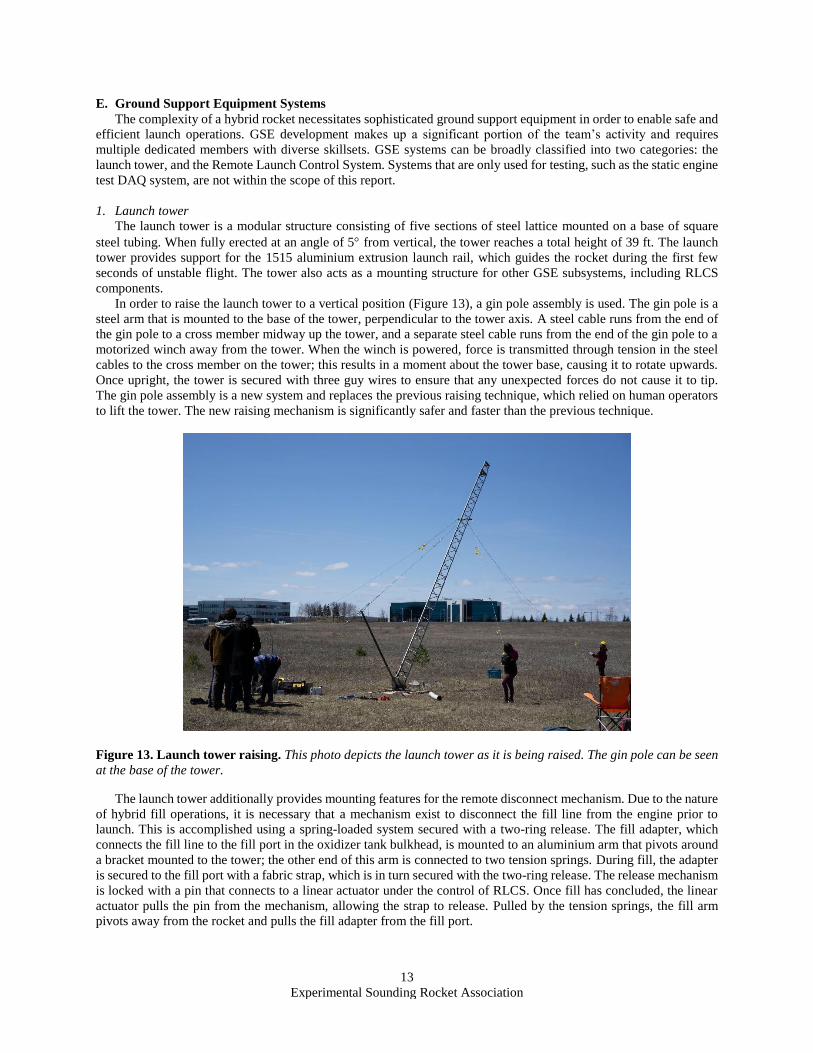
In order to raise the launch tower to a vertical position (Figure 13), a gin pole assembly is used. The gin pole is a
steel arm that is mounted to the base of the tower, perpendicular to the tower axis. A steel cable runs from the end of
the gin pole to a cross member midway up the tower, and a separate steel cable runs from the end of the gin pole to a
motorized winch away from the tower. When the winch is powered, force is transmitted through tension in the steel
cables to the cross member on the tower; this results in a moment about the tower base, causing it to rotate upwards.
Once upright, the tower is secured with three guy wires to ensure that any unexpected forces do not cause it to tip.
The gin pole assembly is a new system and replaces the previous raising technique, which relied on human operators
to lift the tower. The new raising mechanism is significantly safer and faster than the previous technique.
Figure 13. Launch tower raising. This photo depicts the launch tower as it is being raised. The gin pole can be seen
at the base of the tower.
The launch tower additionally provides mounting features for the remote disconnect mechanism. Due to the nature
of hybrid fill operations, it is necessary that a mechanism exist to disconnect the fill line from the engine prior to
launch. This is accomplished using a spring-loaded system secured with a two-ring release. The fill adapter, which
connects the fill line to the fill port in the oxidizer tank bulkhead, is mounted to an aluminium arm that pivots around
a bracket mounted to the tower; the other end of this arm is connected to two tension springs. During fill, the adapter
is secured to the fill port with a fabric strap, which is in turn secured with the two-ring release. The release mechanism
is locked with a pin that connects to a linear actuator under the control of RLCS. Once fill has concluded, the linear
actuator pulls the pin from the mechanism, allowing the strap to release. Pulled by the tension springs, the fill arm
pivots away from the rocket and pulls the fill adapter from the fill port.
14
Experimental Sounding Rocket Association
2. Remote Launch Control System
The Remote Launch Control System is the system that controls all electrical components involved in propellant
loading and other preflight actions required to launch the rocket. It allows the launch operations team to conduct
launch procedures from a safe distance without placing any human operators in danger. The primary objective of
RLCS is to allow the launch system to be operated at a minimum distance of 1 km from the launch tower. Once RLCS
takes control of the launch operations, no human intervention should be required (in any possible error state) that
requires a human to approach the system. In event of total failure, the system must safe all engine and fill systems so
that personnel can approach the rocket without placing themselves in any danger.
RLCS controls the following actuators necessary for fill and engine start:
• The Remote Fill Valve, which controls the entry of NOS into the fill system
• The Line Vent Valve, which opens the fill system to atmosphere in order to vent NOS
• The linear actuator that triggers the remote disconnect mechanism
• Two nichrome coils inside the engine ignition puck
• The Injector Valve, which controls the flow of NOS into the combustion chamber
• The Tank Vent Valve, which allows the oxidizer tank to be vented of NOS
Moreover, RLCS must use sensors to collect the following data, and report that data back to the operator:
• The current state of all valves (open/closed)
• The amount of current flowing through each nichrome coil inside the ignition puck
• The current mass of the rocket, loaded on the rail
• The pressure of oxidizer in the rocket's oxidizer tank
• The pressure of oxidizer in the fill lines
• The pressure of oxidizer in the supply lines
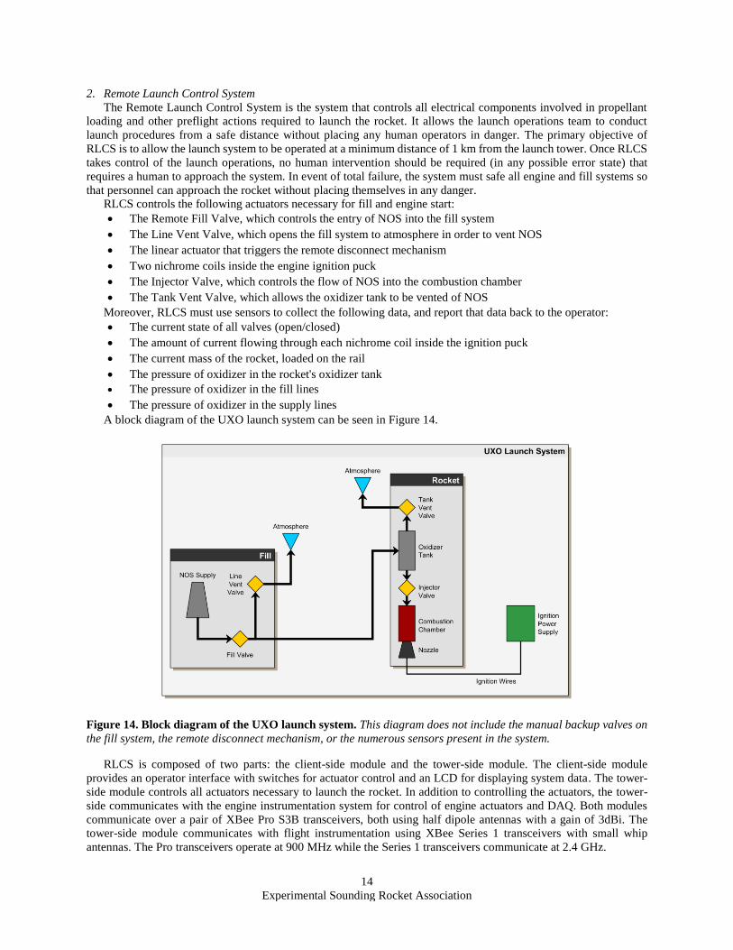
A block diagram of the UXO launch system can be seen in Figure 14.
Figure 14. Block diagram of the UXO launch system. This diagram does not include the manual backup valves on
the fill system, the remote disconnect mechanism, or the numerous sensors present in the system.
RLCS is composed of two parts: the client-side module and the tower-side module. The client-side module
provides an operator interface with switches for actuator control and an LCD for displaying system data. The tower-
side module controls all actuators necessary to launch the rocket. In addition to controlling the actuators, the tower-
side communicates with the engine instrumentation system for control of engine actuators and DAQ. Both modules
communicate over a pair of XBee Pro S3B transceivers, both using half dipole antennas with a gain of 3dBi. The
tower-side module communicates with flight instrumentation using XBee Series 1 transceivers with small whip
antennas. The Pro transceivers operate at 900 MHz while the Series 1 transceivers communicate at 2.4 GHz.
15
Experimental Sounding Rocket Association
The client-side module LCD, radio transceiver, and switches all connect to an Arduino Mega which runs the core
system logic. All switches are connected in series with a key switch to allow the system to be disabled whenever
personnel are nearby the rocket. The ignition switch is in series with a momentary pushbutton to remove the possibility
of a switch being left in the the "fire" position when the system is first started. The client-side also uses a custom
power regulation board. This board is a switching regulator which drops the 11.1 V supply from the battery to 5 V,
which can be used by the microcontroller.
The tower-side module controls external actuators through relay boards, which are cutomed designed PCBs that
feature a DPDT relay, for changing direction of valves or swapping between ignition circuits, and an SPST relay, for
interrupting current to the actuator when it is set to off. The boards also feature current sensors on all actuator outputs,
and logic level shifting for the limit switch signals coming off of the valve, dropping the signal from 12 V to 5 V,
which the microcontroller can read. The batteries in this module are fused to prevent a fire in the event of a short
circuit.
During the design phase of this system, the team considered using higher-powered radio transceivers instead of
the 500mW XBee transceivers that were available. By using higher powered transceivers, the risk of communication
loss could have been decreased. However, the team elected to continue using XBee Pro transceivers since the safe
operating distance of 3000 ft is well within their operational range. Higher-powered transceivers would have required
extensive testing and debugging, as well as significantly more power than the system was designed to use.
RLCS is powered by several 2200 mAh LiPo batteries designed for use in RC cars. These batteries were selected
due to their low cost, size, and very high energy density. Because of their low cost, the team was able to purchase
enough replacements to have a spare for every battery in the system, which relieves the problem of long charge times.
The previous version of RLCS used hand-assembled Veroboard to mount all electrical components. For this
revision, all functionality has been moved to custom designed PCBs. This decision was made to ensure higher
reliability, increased modularity, and to allow use of components available only in surface mount packages, such as
the current sense amplifiers.
III. Mission Concept of Operations Overview
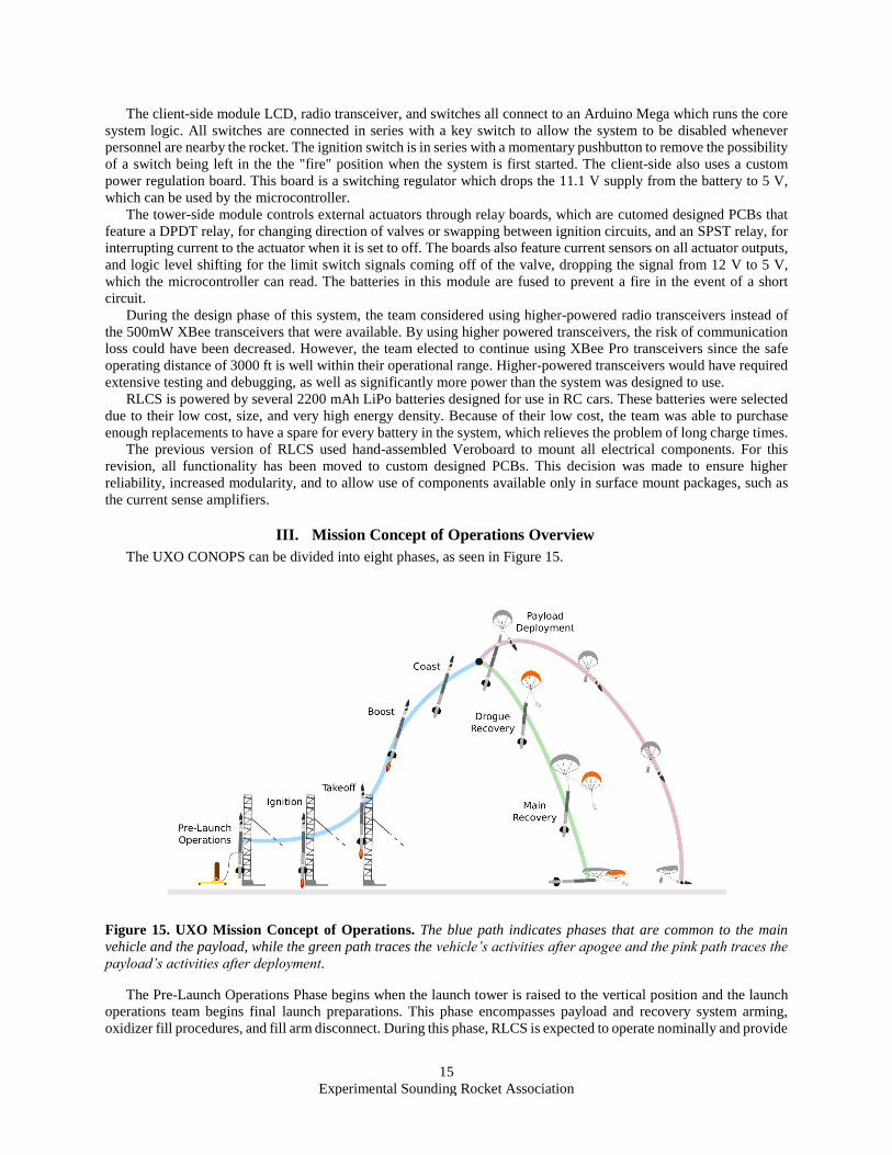
The UXO CONOPS can be divided into eight phases, as seen in Figure 15.
Figure 15. UXO Mission Concept of Operations. The blue path indicates phases that are common to the main
vehicle and the payload, while the green path traces the vehicle’s activities after apogee and the pink path traces the
payload’s activities after deployment.
The Pre-Launch Operations Phase begins when the launch tower is raised to the vertical position and the launch
operations team begins final launch preparations. This phase encompasses payload and recovery system arming,
oxidizer fill procedures, and fill arm disconnect. During this phase, RLCS is expected to operate nominally and provide
16
Experimental Sounding Rocket Association
continuous feedback of oxidizer pressure and rocket mass. This phase ends when the fill arm is disconnected and
permission is given to proceed to ignition.
The Ignition Phase encompasses ignition procedures of the Kismet engine. It begins when the ignition signal is
sent to the primary ignition puck. The puck must ignite successfully. Once puck ignition is confirmed, the injector
valve is opened. This phase ends when Kismet ignites and UXO begins to move.
The Takeoff Phase begins at first vehicle motion. UXO begins accelerating along the launch rail and departs the
rail with a velocity of 76 ft/s and a static stability margin of 2.3 cal.
The Boost Phase begins once UXO departs the launch rail. The engine continues burning for approximately 16
seconds, accelerating the rocket to approximately 678 ft/s and climbing to an altitude of approximately 10500 ft. At
burnout, the stability margin of the rocket is approximately 4.5 cal.
The Glide Phase begins following burnout and lasts for the remainder of UXO’s ascent. As the engine is no longer
producing thrust, the rocket begins to decelerate. UXO reaches an apogee of 12480 ft at 10 seconds after burnout and
36 seconds after engine ignition. The peak stability margin reached during this phase is 4.6 cal.
The Payload Deployment Phase begins at apogee. The payload altimeter detects that apogee has been reached, and
triggers the payload deployment mechanism. The payload module becomes detached from the rest of the vehicle and
begins to descend under its own parachute, falling at a rate of 29 ft/s.
The Drogue Recovery Phase begins 5 seconds after apogee. The recovery altimeters detect that the 5 second apogee
delay has been completed, and trigger the first deployment event. The parachute section is pressurized with CO2,
causing the nylon rivets to shear and detach the recovery electronics section at the mating coupler. The drogue
parachute is pulled out by the force of the deployment event, and inflates, slowing descent rate to 114 ft/s. The main
parachute remains restrained by the two-ring release mechanism. The payload continues to descend independently.
The Main Recovery Phase begins when UXO descends to 1500 ft AGL. The recovery altimeters detect that the
preset altitude has been reached, and trigger the second deployment event. The pyrotechnic cutters are actuated,
severing the strap retaining the main parachute release mechanism. This allows the drag force on the drogue to pull
the main parachute out of the airframe. As the main parachute inflates, it slows UXO’s descent speed to 29 ft/s. The
payload continues to descend independently. This phase concludes once both UXO and the payload have landed.
IV. Conclusions and Lessons Learned
A. Team Management
As the team continues to take on challenging projects and develop increasingly sophisticated systems, the
importance of strong project management cannot be overstated. For all current team members, UXO was the first
rocket they had worked on that was not an iteration of the Vidar series. The team’s approach to development while
iterating on Vidar had been to freeze design on most of the rocket’s systems and choose only a few per design cycle
for focused development. This approach worked very well for iteration and allowed the team to progressively fix
issues with Vidar over the course of multiple years. However, when building a new rocket almost entirely from scratch,
this is clearly not a feasible approach. In order to ensure that all of the systems and projects being worked on were
progressing, not blocked, and would integrate well with each other, the team needed to place more effort on structure
and planning than in previous years. Although the team had not previously held weekly meetings, these became
necessary to ensure that all Project Leads were aware of the expectations for their project and were progressing well.
It became evident midway through the year that meetings alone were not sufficient and a more detailed plan was
necessary if UXO were to be completed in time for the 2018 IREC. These changes reflect that Project Leads, as well
as the Team Lead, must take increasing responsibility for project management in addition to technical work. Delays
that may have only been inconveniences for simpler projects can now mean milestones are missed and other systems
begin to fall behind, and every Project Lead must ensure that they are able to communicate effectively with other team
members if issues begin to appear.
An additional important lesson is the necessity of always having a team member that is designated as having and
is able to take on an overall leadership role. Due to the University of Waterloo’s co-op program, engineering students
alternate between 4 month academic terms in Waterloo and 4 month work terms across a wide variety of locations. In
previous years, Team Leads have retained overall team leadership if they are on work terms that take place outside of
Waterloo. However, it became clear over the course of this year that it can be dangerous to assume that the Team Lead
will be able to dedicate as much time and effort during their work term as when they are on academic term. In order
to ensure that there is always a leader that can keep the team moving and resolve any issues necessary, Team Leads
(and Project Leads to a lesser extent) should plan for their work terms as if they will not be able to contribute much to
the team during the term.
17
Experimental Sounding Rocket Association
In developing UXO, all team members maintained an awareness of the importance of knowledge transfer and
documentation of work. Senior team members took on fewer critical projects than in previous years, and instead acted
in more advisory roles to allow more junior members to develop their technical and project management skills.
Frequent design reviews were held for all projects, both to ensure that there were no significant technical issues and
to allow junior members to become more familiar with the work the team was conducting.
B. Technical Development
As this year was the team’s first in recent memory developing many new systems in parallel, the importance of
frequent testing at the component and system level was reinforced. It is essential to test every system for functionality
prior to integration testing in order to ensure that preliminary issues are identified before they can affect other systems.
However, exhaustive testing at a system level is no substitute for proper integration testing, as there will always be
interactions between systems that cannot be characterized without testing.
After static engine testing, the thrust produced by the Kismet engine was originally characterized as significantly
higher than in reality. This was due to a calibration error on the load cell used to measure thrust. The importance of
proper calibration cannot be overstated, as an incorrect calibration can lead to a major misunderstanding of a system’s
characteristics. In the case of Kismet, the error was caught soon enough that the team was not prevented from
completing design on UXO; however, this will not always be the case. Testing is only significant if there exists a
reliable way to characterize test results.
18
Experimental Sounding Rocket Association
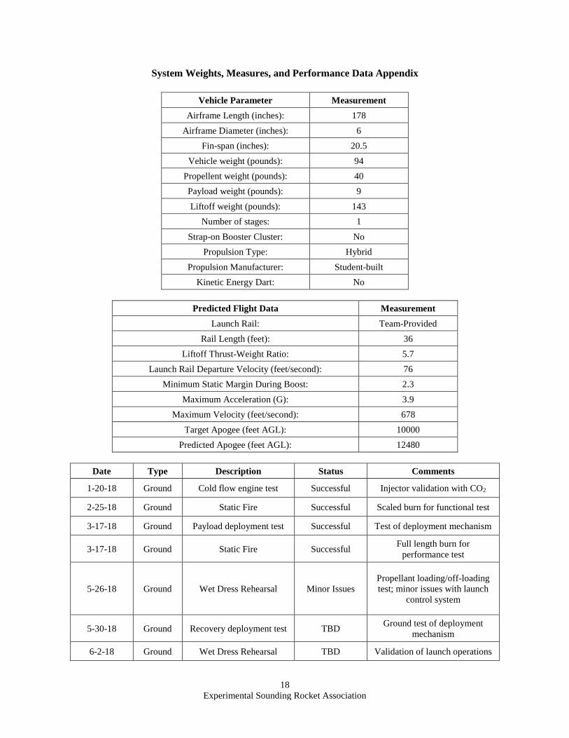
System Weights, Measures, and Performance Data Appendix
Vehicle Parameter Measurement
Airframe Length (inches): 178
Airframe Diameter (inches): 6
Fin-span (inches): 20.5
Vehicle weight (pounds): 94
Propellent weight (pounds): 40
Payload weight (pounds): 9
Liftoff weight (pounds): 143
Number of stages: 1
Strap-on Booster Cluster: No
Propulsion Type: Hybrid
Propulsion Manufacturer: Student-built
Kinetic Energy Dart: No
Predicted Flight Data Measurement
Launch Rail: Team-Provided
Rail Length (feet): 36
Liftoff Thrust-Weight Ratio: 5.7
Launch Rail Departure Velocity (feet/second): 76
Minimum Static Margin During Boost: 2.3
Maximum Acceleration (G): 3.9
Maximum Velocity (feet/second): 678
Target Apogee (feet AGL): 10000
Predicted Apogee (feet AGL): 12480
Date Type Description Status Comments
1-20-18 Ground Cold flow engine test Successful Injector validation with CO2
2-25-18 Ground Static Fire Successful Scaled burn for functional test
3-17-18 Ground Payload deployment test Successful Test of deployment mechanism
3-17-18 Ground Static Fire Successful Full length burn for
performance test
5-26-18 Ground Wet Dress Rehearsal Minor Issues
Propellant loading/off-loading
test; minor issues with launch
control system
5-30-18 Ground Recovery deployment test TBD Ground test of deployment
mechanism
6-2-18 Ground Wet Dress Rehearsal TBD Validation of launch operations
19
Experimental Sounding Rocket Association
Project Test Reports Appendix
The oxidizer tank was hydrostatically tested to 1500 psi for 2 hours. Since the pressure relief valve on the tank
will be set to 1000 psi at competition, this corresponds to a hydrostatic test at a FOS of 1.5 times the maximum
operating pressure. The maximum operational time of the oxidizer tank was identified as 1 hour, which is the amount
of time it would take to vent the oxidizer if the launch attempt had to be aborted. For this reason, the tank was
hydrostatically tested for 2 hours, which is equal to twice the maximum operational time.
A hydrostatic test was performed on the combustion chamber to 1050 psi (FOS of 2.1) for 2 minutes. Since the
tank is not able to be hydrostatically tested with the nozzle in place, an end cap was made to sit in the nozzle’s position
and seal the tank. During engine testing, the measured pressure drop across the injector was 50%; therefore, the
maximum operating pressure of the combustion chamber was determined to be 500 psi. The combustion chamber is
in operation for less than 1 minute, during the engine burn, so the tank was hydrostatically tested for 2 minutes, which
is equal to twice the maximum operational time.
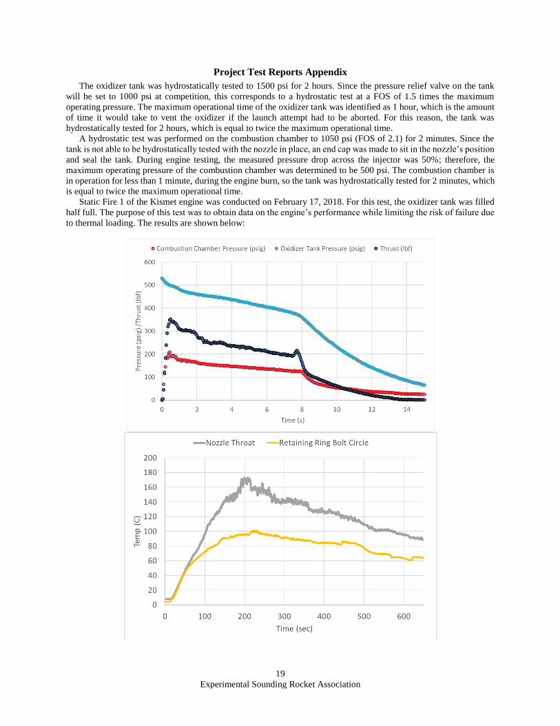
Static Fire 1 of the Kismet engine was conducted on February 17, 2018. For this test, the oxidizer tank was filled
half full. The purpose of this test was to obtain data on the engine’s performance while limiting the risk of failure due
to thermal loading. The results are shown below:
20
Experimental Sounding Rocket Association
It is apparent that the combustion chamber pressure tap became clogged sometime during the test; however, it is
realistic to assume that the pressure at the start of the burn was correctly measured. Since this test was conducted at
low temperature, the oxidizer pressure and also the thrust are lower than expected at competition. Changes that were
made based on this test were:
• Modification of the fuel grain geometry to achieve a higher peak thrust and lower the O/F ratio
• Addition of an aluminium boat-tail in order to reduce the post firing temperature of the combustion
chamber shell at the nozzle throat (in order to avoid annealing)
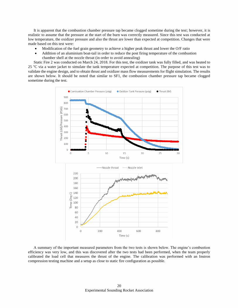
Static Fire 2 was conducted on March 24, 2018. For this test, the oxidizer tank was fully filled, and was heated to
25 °C via a water jacket to simulate the tank temperature expected at competition. The purpose of this test was to
validate the engine design, and to obtain thrust and oxidizer mass flow measurements for flight simulation. The results
are shown below. It should be noted that similar to SF1, the combustion chamber pressure tap became clogged
sometime during the test.
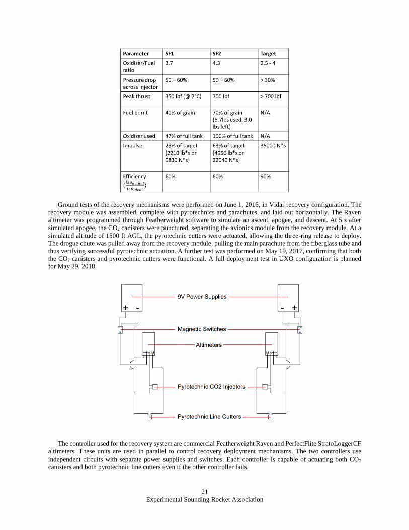
A summary of the important measured parameters from the two tests is shown below. The engine’s combustion
efficiency was very low, and this was discovered after the two tests had been performed, when the team properly
calibrated the load cell that measures the thrust of the engine. The calibration was performed with an Instron
compression testing machine and a setup as close to static fire configuration as possible.
21
Experimental Sounding Rocket Association
Ground tests of the recovery mechanisms were performed on June 1, 2016, in Vidar recovery configuration. The
recovery module was assembled, complete with pyrotechnics and parachutes, and laid out horizontally. The Raven
altimeter was programmed through Featherweight software to simulate an ascent, apogee, and descent. At 5 s after
simulated apogee, the CO2 canisters were punctured, separating the avionics module from the recovery module. At a
simulated altitude of 1500 ft AGL, the pyrotechnic cutters were actuated, allowing the three-ring release to deploy.
The drogue chute was pulled away from the recovery module, pulling the main parachute from the fiberglass tube and
thus verifying successful pyrotechnic actuation. A further test was performed on May 19, 2017, confirming that both
the CO2 canisters and pyrotechnic cutters were functional. A full deployment test in UXO configuration is planned
for May 29, 2018.
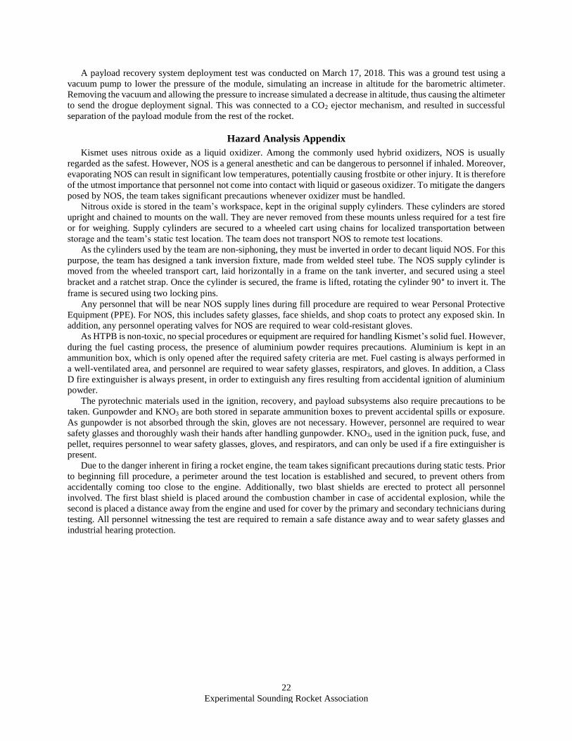
The controller used for the recovery system are commercial Featherweight Raven and PerfectFlite StratoLoggerCF
altimeters. These units are used in parallel to control recovery deployment mechanisms. The two controllers use
independent circuits with separate power supplies and switches. Each controller is capable of actuating both CO2
canisters and both pyrotechnic line cutters even if the other controller fails.
22
Experimental Sounding Rocket Association
A payload recovery system deployment test was conducted on March 17, 2018. This was a ground test using a
vacuum pump to lower the pressure of the module, simulating an increase in altitude for the barometric altimeter.
Removing the vacuum and allowing the pressure to increase simulated a decrease in altitude, thus causing the altimeter
to send the drogue deployment signal. This was connected to a CO2 ejector mechanism, and resulted in successful
separation of the payload module from the rest of the rocket.
Hazard Analysis Appendix
Kismet uses nitrous oxide as a liquid oxidizer. Among the commonly used hybrid oxidizers, NOS is usually
regarded as the safest. However, NOS is a general anesthetic and can be dangerous to personnel if inhaled. Moreover,
evaporating NOS can result in significant low temperatures, potentially causing frostbite or other injury. It is therefore
of the utmost importance that personnel not come into contact with liquid or gaseous oxidizer. To mitigate the dangers
posed by NOS, the team takes significant precautions whenever oxidizer must be handled.
Nitrous oxide is stored in the team’s workspace, kept in the original supply cylinders. These cylinders are stored
upright and chained to mounts on the wall. They are never removed from these mounts unless required for a test fire
or for weighing. Supply cylinders are secured to a wheeled cart using chains for localized transportation between
storage and the team’s static test location. The team does not transport NOS to remote test locations.
As the cylinders used by the team are non-siphoning, they must be inverted in order to decant liquid NOS. For this
purpose, the team has designed a tank inversion fixture, made from welded steel tube. The NOS supply cylinder is
moved from the wheeled transport cart, laid horizontally in a frame on the tank inverter, and secured using a steel
bracket and a ratchet strap. Once the cylinder is secured, the frame is lifted, rotating the cylinder 90° to invert it. The
frame is secured using two locking pins.
Any personnel that will be near NOS supply lines during fill procedure are required to wear Personal Protective
Equipment (PPE). For NOS, this includes safety glasses, face shields, and shop coats to protect any exposed skin. In
addition, any personnel operating valves for NOS are required to wear cold-resistant gloves.
As HTPB is non-toxic, no special procedures or equipment are required for handling Kismet’s solid fuel. However,
during the fuel casting process, the presence of aluminium powder requires precautions. Aluminium is kept in an
ammunition box, which is only opened after the required safety criteria are met. Fuel casting is always performed in
a well-ventilated area, and personnel are required to wear safety glasses, respirators, and gloves. In addition, a Class
D fire extinguisher is always present, in order to extinguish any fires resulting from accidental ignition of aluminium
powder.
The pyrotechnic materials used in the ignition, recovery, and payload subsystems also require precautions to be
taken. Gunpowder and KNO3 are both stored in separate ammunition boxes to prevent accidental spills or exposure.
As gunpowder is not absorbed through the skin, gloves are not necessary. However, personnel are required to wear
safety glasses and thoroughly wash their hands after handling gunpowder. KNO3, used in the ignition puck, fuse, and
pellet, requires personnel to wear safety glasses, gloves, and respirators, and can only be used if a fire extinguisher is
present.
Due to the danger inherent in firing a rocket engine, the team takes significant precautions during static tests. Prior
to beginning fill procedure, a perimeter around the test location is established and secured, to prevent others from
accidentally coming too close to the engine. Additionally, two blast shields are erected to protect all personnel
involved. The first blast shield is placed around the combustion chamber in case of accidental explosion, while the
second is placed a distance away from the engine and used for cover by the primary and secondary technicians during
testing. All personnel witnessing the test are required to remain a safe distance away and to wear safety glasses and
industrial hearing protection.
23
Experimental Sounding Rocket Association
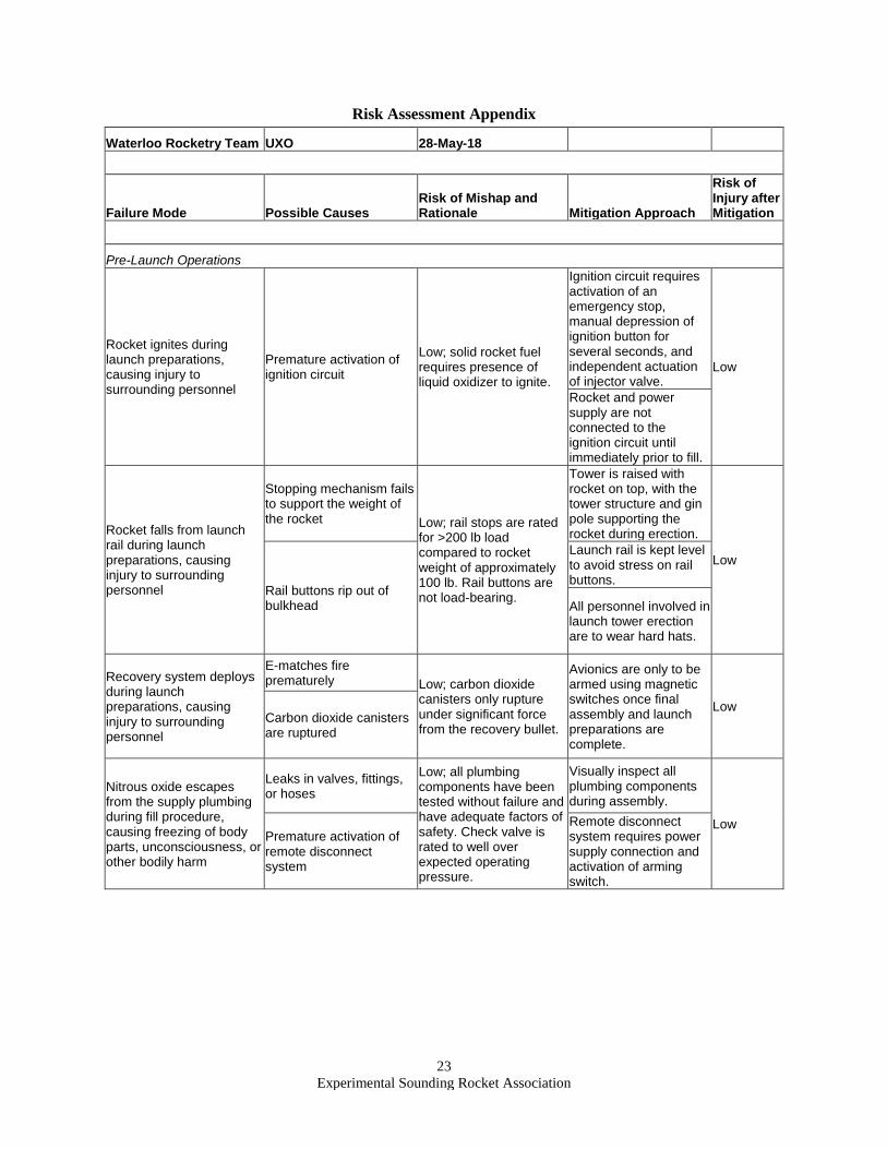
Risk Assessment Appendix
Waterloo Rocketry Team UXO 28-May-18
Failure Mode Possible Causes Risk of Mishap and Rationale Mitigation Approach
Risk of Injury after Mitigation
Pre-Launch Operations
Rocket ignites during launch preparations, causing injury to surrounding personnel
Premature activation of ignition circuit
Low; solid rocket fuel requires presence of liquid oxidizer to ignite.
Ignition circuit requires activation of an emergency stop, manual depression of ignition button for several seconds, and independent actuation of injector valve.
Low
Rocket and power supply are not connected to the ignition circuit until immediately prior to fill.
Rocket falls from launch rail during launch preparations, causing injury to surrounding personnel
Stopping mechanism fails to support the weight of the rocket Low; rail stops are rated
for >200 lb load compared to rocket weight of approximately 100 lb. Rail buttons are not load-bearing.
Tower is raised with rocket on top, with the tower structure and gin pole supporting the rocket during erection.
Low
Rail buttons rip out of bulkhead
Launch rail is kept level to avoid stress on rail buttons.
All personnel involved in launch tower erection are to wear hard hats.
Recovery system deploys during launch preparations, causing injury to surrounding personnel
E-matches fire prematurely Low; carbon dioxide
canisters only rupture under significant force from the recovery bullet.
Avionics are only to be armed using magnetic switches once final assembly and launch preparations are complete.
Low Carbon dioxide canisters are ruptured
Nitrous oxide escapes from the supply plumbing during fill procedure, causing freezing of body parts, unconsciousness, or other bodily harm
Leaks in valves, fittings, or hoses
Low; all plumbing components have been tested without failure and have adequate factors of safety. Check valve is rated to well over expected operating pressure.
Visually inspect all plumbing components during assembly.
Low Premature activation of remote disconnect system
Remote disconnect system requires power supply connection and activation of arming switch.
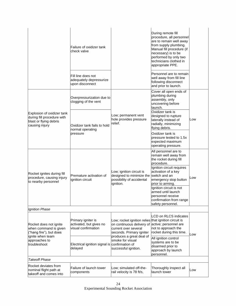
24
Experimental Sounding Rocket Association
Failure of oxidizer tank check valve
During remote fill procedure, all personnel are to remain well away from supply plumbing. Manual fill procedure (if necessary) is to be performed by only two technicians clothed in appropriate PPE.
Fill line does not adequately depressurize upon disconnect
Personnel are to remain well away from fill line following disconnect and prior to launch.
Explosion of oxidizer tank during fill procedure with blast or flying debris causing injury
Overpressurization due to clogging of the vent
Low; permanent vent hole provides pressure relief.
Cover all open ends of plumbing during assembly, only uncovering before launch.
Low
Oxidizer tank fails to hold normal operating pressure
Oxidizer tank is designed to rupture laterally instead of radially, minimizing flying debris.
Oxidizer tank is pressure tested to 1.5x expected maximum operating pressure.
Rocket ignites during fill procedure, causing injury to nearby personnel
Premature activation of ignition circuit
Low; ignition circuit is designed to minimize the possibility of accidental ignition.
All personnel are to remain well away from the rocket during fill procedure.
Low
Ignition circuit requires activation of a key switch and an emergency stop button prior to arming.
Ignition circuit is not armed until launch personnel receive confirmation from range safety personnel.
Ignition Phase
Rocket does not ignite when command is given (“hang fire”), but does ignite when team approaches to troubleshoot
Primary igniter is activated, but gives no visual confirmation
Low; rocket ignition relies on continuous delivery of current over several seconds. Primary igniter produces a great deal of smoke for visual confirmation of successful ignition.
LCD on RLCS indicates that ignition circuit is active; personnel are not to approach the rocket during this time.
Low
Electrical ignition signal is delayed
All ignition control systems are to be disarmed prior to approach by launch personnel.
Takeoff Phase
Rocket deviates from nominal flight path at takeoff and comes into
Failure of launch tower components
Low; simulated off-the-rail velocity is 78 ft/s,
Thoroughly inspect all launch tower
Low
25
Experimental Sounding Rocket Association
contact with personnel at high speeds
resulting in acceptable stability.
components before assembly.
Unexpectedly low off-the-rail velocity resulting in low stability
Direct launch tower away from the campsite.
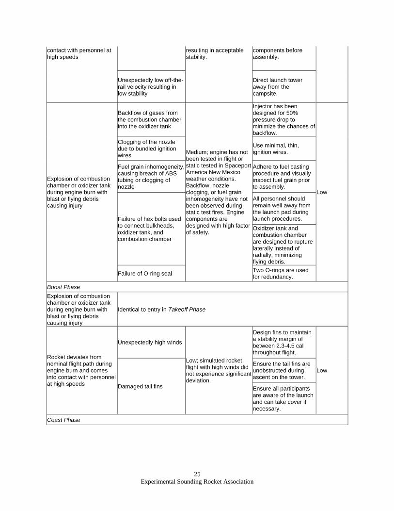
Explosion of combustion chamber or oxidizer tank during engine burn with blast or flying debris causing injury
Backflow of gases from the combustion chamber into the oxidizer tank
Medium; engine has not been tested in flight or static tested in Spaceport America New Mexico weather conditions. Backflow, nozzle clogging, or fuel grain inhomogeneity have not been observed during static test fires. Engine components are designed with high factor of safety.
Injector has been designed for 50% pressure drop to minimize the chances of backflow.
Low
Clogging of the nozzle due to bundled ignition wires
Use minimal, thin, ignition wires.
Fuel grain inhomogeneity, causing breach of ABS tubing or clogging of nozzle
Adhere to fuel casting procedure and visually inspect fuel grain prior to assembly.
Failure of hex bolts used to connect bulkheads, oxidizer tank, and combustion chamber
All personnel should remain well away from the launch pad during launch procedures.
Oxidizer tank and combustion chamber are designed to rupture laterally instead of radially, minimizing flying debris.
Failure of O-ring seal Two O-rings are used for redundancy.
Boost Phase
Explosion of combustion chamber or oxidizer tank during engine burn with blast or flying debris causing injury
Identical to entry in Takeoff Phase
Rocket deviates from nominal flight path during engine burn and comes into contact with personnel at high speeds
Unexpectedly high winds
Low; simulated rocket flight with high winds did not experience significant deviation.
Design fins to maintain a stability margin of between 2.3-4.5 cal throughout flight.
Low
Damaged tail fins
Ensure the tail fins are unobstructed during ascent on the tower.
Ensure all participants are aware of the launch and can take cover if necessary.
Coast Phase
26
Experimental Sounding Rocket Association
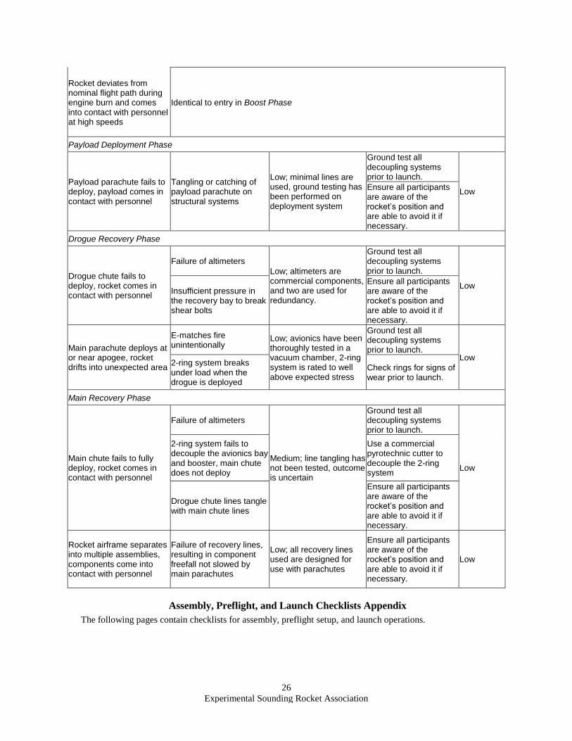
Rocket deviates from nominal flight path during engine burn and comes into contact with personnel at high speeds
Identical to entry in Boost Phase
Payload Deployment Phase
Payload parachute fails to deploy, payload comes in contact with personnel
Tangling or catching of payload parachute on structural systems
Low; minimal lines are used, ground testing has been performed on deployment system
Ground test all decoupling systems prior to launch.
Low Ensure all participants are aware of the rocket’s position and are able to avoid it if necessary.
Drogue Recovery Phase
Drogue chute fails to deploy, rocket comes in contact with personnel
Failure of altimeters
Low; altimeters are commercial components, and two are used for redundancy.
Ground test all decoupling systems prior to launch.
Low Insufficient pressure in the recovery bay to break shear bolts
Ensure all participants are aware of the rocket’s position and are able to avoid it if necessary.
Main parachute deploys at or near apogee, rocket drifts into unexpected area
E-matches fire unintentionally
Low; avionics have been thoroughly tested in a vacuum chamber, 2-ring system is rated to well above expected stress
Ground test all decoupling systems prior to launch.
Low 2-ring system breaks under load when the drogue is deployed
Check rings for signs of wear prior to launch.
Main Recovery Phase
Main chute fails to fully deploy, rocket comes in contact with personnel
Failure of altimeters
Medium; line tangling has not been tested, outcome is uncertain
Ground test all decoupling systems prior to launch.
Low
2-ring system fails to decouple the avionics bay and booster, main chute does not deploy
Use a commercial pyrotechnic cutter to decouple the 2-ring system
Drogue chute lines tangle with main chute lines
Ensure all participants are aware of the rocket’s position and are able to avoid it if necessary.
Rocket airframe separates into multiple assemblies, components come into contact with personnel
Failure of recovery lines, resulting in component freefall not slowed by main parachutes
Low; all recovery lines used are designed for use with parachutes
Ensure all participants are aware of the rocket’s position and are able to avoid it if necessary.
Low
Assembly, Preflight, and Launch Checklists Appendix
The following pages contain checklists for assembly, preflight setup, and launch operations.
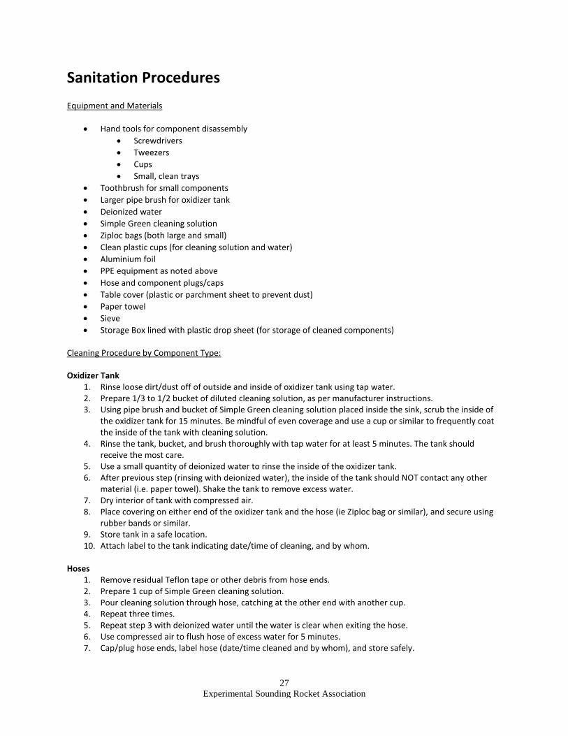
27
Experimental Sounding Rocket Association
Sanitation Procedures Equipment and Materials
• Hand tools for component disassembly
• Screwdrivers
• Tweezers
• Cups
• Small, clean trays
• Toothbrush for small components
• Larger pipe brush for oxidizer tank
• Deionized water
• Simple Green cleaning solution
• Ziploc bags (both large and small)
• Clean plastic cups (for cleaning solution and water)
• Aluminium foil
• PPE equipment as noted above
• Hose and component plugs/caps
• Table cover (plastic or parchment sheet to prevent dust)
• Paper towel
• Sieve
• Storage Box lined with plastic drop sheet (for storage of cleaned components) Cleaning Procedure by Component Type: Oxidizer Tank
1. Rinse loose dirt/dust off of outside and inside of oxidizer tank using tap water. 2. Prepare 1/3 to 1/2 bucket of diluted cleaning solution, as per manufacturer instructions. 3. Using pipe brush and bucket of Simple Green cleaning solution placed inside the sink, scrub the inside of
the oxidizer tank for 15 minutes. Be mindful of even coverage and use a cup or similar to frequently coat the inside of the tank with cleaning solution.
4. Rinse the tank, bucket, and brush thoroughly with tap water for at least 5 minutes. The tank should receive the most care.
5. Use a small quantity of deionized water to rinse the inside of the oxidizer tank. 6. After previous step (rinsing with deionized water), the inside of the tank should NOT contact any other
material (i.e. paper towel). Shake the tank to remove excess water. 7. Dry interior of tank with compressed air. 8. Place covering on either end of the oxidizer tank and the hose (ie Ziploc bag or similar), and secure using
rubber bands or similar. 9. Store tank in a safe location. 10. Attach label to the tank indicating date/time of cleaning, and by whom.
Hoses
1. Remove residual Teflon tape or other debris from hose ends. 2. Prepare 1 cup of Simple Green cleaning solution. 3. Pour cleaning solution through hose, catching at the other end with another cup. 4. Repeat three times. 5. Repeat step 3 with deionized water until the water is clear when exiting the hose. 6. Use compressed air to flush hose of excess water for 5 minutes. 7. Cap/plug hose ends, label hose (date/time cleaned and by whom), and store safely.
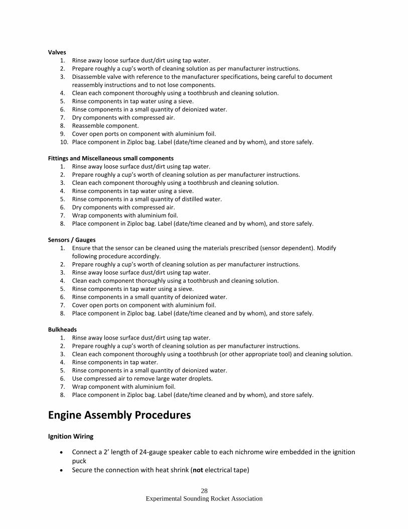
28
Experimental Sounding Rocket Association
Valves 1. Rinse away loose surface dust/dirt using tap water. 2. Prepare roughly a cup’s worth of cleaning solution as per manufacturer instructions. 3. Disassemble valve with reference to the manufacturer specifications, being careful to document
reassembly instructions and to not lose components. 4. Clean each component thoroughly using a toothbrush and cleaning solution. 5. Rinse components in tap water using a sieve. 6. Rinse components in a small quantity of deionized water. 7. Dry components with compressed air. 8. Reassemble component. 9. Cover open ports on component with aluminium foil. 10. Place component in Ziploc bag. Label (date/time cleaned and by whom), and store safely.
Fittings and Miscellaneous small components
1. Rinse away loose surface dust/dirt using tap water. 2. Prepare roughly a cup’s worth of cleaning solution as per manufacturer instructions. 3. Clean each component thoroughly using a toothbrush and cleaning solution. 4. Rinse components in tap water using a sieve. 5. Rinse components in a small quantity of distilled water. 6. Dry components with compressed air. 7. Wrap components with aluminium foil. 8. Place component in Ziploc bag. Label (date/time cleaned and by whom), and store safely.
Sensors / Gauges
1. Ensure that the sensor can be cleaned using the materials prescribed (sensor dependent). Modify following procedure accordingly.
2. Prepare roughly a cup’s worth of cleaning solution as per manufacturer instructions. 3. Rinse away loose surface dust/dirt using tap water. 4. Clean each component thoroughly using a toothbrush and cleaning solution. 5. Rinse components in tap water using a sieve. 6. Rinse components in a small quantity of deionized water. 7. Cover open ports on component with aluminium foil. 8. Place component in Ziploc bag. Label (date/time cleaned and by whom), and store safely.
Bulkheads
1. Rinse away loose surface dust/dirt using tap water. 2. Prepare roughly a cup’s worth of cleaning solution as per manufacturer instructions. 3. Clean each component thoroughly using a toothbrush (or other appropriate tool) and cleaning solution. 4. Rinse components in tap water. 5. Rinse components in a small quantity of deionized water. 6. Use compressed air to remove large water droplets. 7. Wrap component with aluminium foil. 8. Place component in Ziploc bag. Label (date/time cleaned and by whom), and store safely.
Engine Assembly Procedures
Ignition Wiring
• Connect a 2’ length of 24-gauge speaker cable to each nichrome wire embedded in the ignition puck
• Secure the connection with heat shrink (not electrical tape)
29
Experimental Sounding Rocket Association
• Ensure continuity in each circuit with a multimeter Combustion Chamber Notes:
• Do not assume anything is sanitized • Ensure tools used to handle sanitized parts are also sanitized • Use clean gloves for installation to avoid contamination • Keep all parts and assemblies clean throughout the assembly process
Procedure: • Remove any old o-rings • Ensure injector and upstream portion of bulkhead is sanitized (ref. Sanitation Procedure) • Install injector o-ring on injector bulkhead • Bolt injector to bulkhead • Install external o-rings on injector bulkhead • Install o-rings on nozzle • Place nozzle on retaining ring • Wrap o-rings securely with painter’s tape to keep clean • Apply caulking to female lip of fuel grain • Apply a small amount of caulking to male end of nozzle • Join fuel grain and nozzle • Clean excess caulking • Remove tape • Place bolt hole plugs into the nozzle end of combustion chamber tube, ensuring they protrude
to the surface of the tube. Secure into place with rubber band • Slide combustion chamber tube over fuel grain assembly and bolt into place, checking for ripped
o-rings • Slide ignition wiring down the fuel grain and out the nozzle • Caulk male end of fuel grain and female end of spacer • Attach spacer to fuel grain • Loop the ends of the ignition wire to the surface of the tube and tape • Cover the nozzle end of the assembly • Place bolt hole plugs into the injector end of combustion chamber tube, ensuring they protrude
to the surface of the tube. Secure into place with rubber band • Caulk male end of spacer and female end of injector bulkhead • Slide injector bulkhead onto combustion chamber assembly • Remove bolt hole plugs, and install bolts, checking for ripped o-rings
Oxidizer Tank Notes:
• Do not assume anything is sanitized • Use gloves for installation to avoid contamination
Procedure: • Sanitize everything that will contact oxidizer (ref. Sanitation Procedure) • Put check valve on bottom oxidizer bulkhead, make sure the arrow on it is pointed upwards to
allow the flow going inside the oxidizer tank • Record the dip tube length and insert it on top oxidizer bulkhead • Install o-rings • Place bolt hole plugs into one bottom of tank, secure into place with rubber band
30
Experimental Sounding Rocket Association
• Ensure that the plugs do not protrude into the tank • Slide bottom oxidizer bulkhead into place, ensuring the holes align while inserting • Remove plugs and bolt injector bulkhead into place, checking for ripped o-rings • Place bolt hole plugs into holes on the top side of the tank, secure and check for protruding
plugs • Align top bulkhead such that the vent port is aligned with the fill port • Slide top bulkhead into place, ensuring the holes align • Remove plugs and bolt vent bulkhead into place, checking for ripped o-rings
Recovery System Setup Procedures
Inspection
• Ensure all components are undamaged
• Ensure that all pyrotechnics and batteries are disconnected and shorted before starting Wiring
• Ensure that all pyrotechnics and batteries are disconnected and shorted before wiring
• Check that all circuit components are properly mounted to the sled with proper spacers, screws, and nuts
• Ensure all switches are in the energized position
• Check continuity between batteries and altimeters
• Turn all switches to the non-energized position
• Check batteries for full capacity (nominal 9 V)
• Install batteries correctly in battery holders CO2 System Installation
• Ensure all ejection device wires and batteries are disconnected from the electronics bay before proceeding
• Ensure the two CO2 ejection devices are installed into the bulkhead
• Install two 38 gram CO2 cylinders into the ejection devices, using two washers to ensure CO2 vent holes are unobstructed. Use Teflon tape on the threads of the CO2 cylinder when connecting
GPS System
• Ensure GPS battery is fully charged
• Ensure GPS is functional after connecting battery
• Turn GPS system off by waving magnet over the magnetic switch Sled Installation
• Ensure all wires are tucked away to prevent pinching during installation
• Ensure the CO2 cylinders are installed into the CO2 ejection device
• Ensure that the batteries are installed in the battery holder
• Slide the sled onto the central threaded rod
• Connect the altimeters to the circular connectors using the screw terminals
• Check continuity between recovery bay connector pins and altimeters
31
Experimental Sounding Rocket Association
CO2 Ejector Setup
• Place igniter and wires inside igniter cylinder and center igniter in cylinder using tissue paper
• Place epoxy on igniter wires so that when the igniters are pulled, the wires do not pull out of the igniter cylinder
• Ensure igniter is placed so that it is flush with the rim of the cylinder that touches the puncturing cylinder
• Place aluminium foil on the working surface
• Place a separate piece of aluminium foil on the working surface for holding and pouring the gunpowder
• Place avionics assembly on the first aluminium sheet with the injector body opening upwards such that the entire body is grounded
• Place O-ring on puncturing cylinder and lightly lubricate with spray silicone lubricant making sure to wipe off excess lubricant
• Place puncturing cylinder in injector body
• Fill puncturing cylinder to the rim with FFFF gunpowder
• Ensure igniter leads remain shorted
• Place O-ring on igniter cylinder and lubricate
• Place igniter cylinder on top of puncturing cylinder and push down until igniter cylinder is flush with injector body
• Ensure gunpowder vent holes are clear of obstructions and cover lightly with masking tape
• Run igniter wires through body cap and screw cap on tightly
• Check for movement of the igniter wires
• If moving, take apart and reseat igniter so that it is seated firmly in place Pyrotechnic Cutter Setup
• Slide an O-Ring into the bottom of the cutter to act as a bumper for the piston
• Insert recovery dual ring rope through the hole of the cutter
• Trim excess rope
• Insert shearing piston
• Insert black powder
• Insert E-match
• Install o-rings to act as seal
• Slide hex screw over E-match leads and screw into cutter Parachute Section Assembly
• Ensure that all recovery lines are free and not tangled
• Ensure that the 9 V batteries are disconnected
• Fold the main parachute, gore by gore, in an accordion-style pattern
• Fold the main parachute vertically in half
• Roll the main parachute from the top towards the main parachute lines
• Pack the rolled parachute into the parachute bag so that the main parachute lines extend from one of the open corners
• Secure the main parachute lines over the parachute bag cover using the elastics
• Use the carabiner to connect the main parachute line to the main coupling line
• Connect the two-ring release mechanism and secure using the dual ring rope
32
Experimental Sounding Rocket Association
• Secure the pyrotechnic line cutters to the primary recovery line using electrical tape
• Connect the pyrotechnic leads to the connectors on the primary recovery line
• Secure the drogue parachute line to the base of the avionics module
• Pack the parachute bag into the recovery module and push it towards the engine end
• Fasten the eyebolt to the top of the vent bulkhead with a lock washer and Loctite
• Wrap a fireproof cloth around the pyrotechnic line cutters to protect main parachute and recovery lines from the black powder burn
• Apply a thick layer of grease to the coupler at the base of the recovery tube and a thin layer of grease on the vent bulkhead
• Insert the vent bulkhead into the recovery module
• Secure the vent bulkhead to the recovery module coupler using 6x 1/4"-28 (1/2") screws
• Connect the circular connector from the primary recovery line to the avionics module
• Pack the drogue parachute and the remaining recovery lines into the recovery module
• Confirm that the altimeters are off
• Make all appropriate electrical connections at the avionics terminals
• Insert the 9V batteries into their mounts
• Slide the fiberglass airframe section over the sled
• Thread the top coupler onto the avionics threaded rod until it mates with the airframe section
• Tighten the nut on the bottom of the lower avionics coupler
• Wrap a fireproof cloth around the igniter cylinders to protect recovery lines and parachutes from the black powder burn
• Apply a layer of grease to the avionics and recovery couplers
• Place the avionics module coupler over the recovery module coupler
• Secure the avionics and recovery modules together with shear pins
Payload Setup Procedures
Assembly
• Ensure all components are undamaged
• Ensure the CubeSat is fully assembled
• Assemble one CO2 ejector as per the instructions in the Recovery System Setup Procedures and secure it to the payload recovery strap
• Connect the e-match to the payload deployment electronics
• Connect the payload recovery strap to the CubeSat
• Slide the CubeSat into the deployment mount
• Connect the base coupler of the deployment mount to the top coupler of the recovery avionics section and secure it with three shear pins
Launch Tower Procedures
Assembly Checks • Ensure all ¼” cable clamps are torqued to 4 ¾ lbs.ft (57 lbs.in) minimum • Ensure all 3/16” cable clamps are torqued to 3 ¾ lbs.ft (45 lbs.in) minimum • Ensure that there are a minimum of 2 threads sticking sticking out the end of the turnbuckles
33
Experimental Sounding Rocket Association
• Ensure that cable assemblies are at least the lengths specified in the “Gin Pole Mechanism Drawings”
• Ensure that the “Connecting Wire ASY” and “Puller Wire ASY” are assembled onto the long gin pole. A section of the “Puller Wire ASY” will not be connected to the winch; this is what should be on the gin pole
• Have the hand drill set on low speed. Max rpm on low speed is 600 rpm, which is also the rpm rating of the winch
• Ensure there is sufficient lubrication on winch gears
Launch Pad Installation Procedure
Estimated time: 10 min
Technicians Required: 2
Tools Required: • Sledgehammer • Strike plate • Level measurement device
1. Identify a fairly flat piece of land, unobstructed by plants 2. Place the launch pad on the ground. If the ground is soft, place several 2x4’s underneath the
pad, evenly spaced 3. Level the launch pad by adding/removing ground as required. Max of 2deg tilt is acceptable 4. Drive stakes through each corner of the launch pad legs, leaving about 1”-2” sticking out
Gin Pole Installation
Estimated Time: 1 min
Technicians Required: 3
Tools Required • Adjustable wrench/ratchet wrench x2 • Long Gin Pole section
1. Ensure the pad is rotated to “tower vertical” position 2. Disassemble the bolt and nut on the Short Gin Pole (already installed on the pad) 3. Slide the Long Gin Pole onto the Short Gin Pole 4. Use the bolt and nut to fasten the sections together, and tighten with wrenches
Ground Anchor Installation
Estimated Time: 25 (5 min per anchor). Time is reduced with more technicians and hammers
Technicians Required: 1 (per sledgehammer)
34
Experimental Sounding Rocket Association
Tools Required • Sledgehammer • Short stake • Medium stake • Long stake • Strike plate • Measuring tape (at least 22’) • 5x ground anchors
PPE
• Safety glasses (per sledgehammer)
1. Locate a point 18’ away from the pivot point of the launch tower. Line up this point with the gin
pole (installed on the tower) 2. Use the short stake, strike plate, and sledgehammer to drive two anchors vertically down at this
location. Switch to the medium, then long stake when there is insufficient length of rod 3. Leave 2” of cable sticking out of the ground, close enough that they can be routed to attach at a
single point 4. Pull on the cable to lock the anchor in the ground 5. Locate three points 16’ away from the pivot point of the launch tower, in the geometry shown in
“Guy Wire Schematic” 6. Drive at one anchor at each point.
Winch Installation
Please see drawings for details
Estimated Time: 30 sec
Technicians Required: 1
1. Ensure the cable on the winch is fully retracted 2. Snap the carabiner on the winch frame to the both ground anchors. Ensure the winch cable is
facing the pad 3. Ensure the carabiner is twist locked 4. Extend the winch cable until it reaches the “Puller Wire ASY”, which is installed on the gin pole 5. Snap the carabiner from the “Puller Wire ASY” onto the winch cable 6. Ensure the carabiner is twist locked
Tower Installation Procedure
Estimated Time: 30 min
Technicians Required: 3
Tools Required • Hand drill with ⅝” socket and adapter • Winch handle
35
Experimental Sounding Rocket Association
PPE
• Gloves x1 pair (for holding the wire on the winch)
1. Locate the turnbuckle on the “Connecting Wire ASY” closest to the gin pole. Leave 2 inches of
threads sticking out either end 2. Place technician #1 at the winch. This technician should have the hand drill/handle 3. Place technician #2 between the winch and the gin pole. This technician should hold the winch
wire with gloves 4. Place technician #3 at the pad, holding the gin pole 5. Unwind the winch, and rotate the gin pole until it hits the launch pad
• Technician #1: Use the hand drill/winch to unwind the winch cable
• Technician #2: Keep tension on the winch cable
• Technician #3: Rotate the gin pole to keep tension on the wire 6. Install the tower (see “Tower Assembly Procedure”) onto the launch pad 7. Install any other GSE required for the tower before it is lifted 8. Snap the carabiner from the “Connecting Wire Assembly” to the “Cable Mount Assembly” on
the tower 9. Tighten the turnbuckle on the connecting wire assembly to prevent slack
Tower Raising Procedure
Estimated Time: 2 min (based on test)
Technicians Required: 6
Tools Required • Hand drill with ⅝” socket and adapter for the socket • Winch handle • Wooden rod (for adjusting wire)
PPE
• Gloves x4 pairs (for handling the wire) • Hard hat x2 • Safety glasses x7
1. Place technicians #1 to #2 at each guy wire, pulling with the tower rotation direction. Gloves
should be worn 2. Place technician #3 at the guy wire, pulling against the tower rotation direction. Gloves should
be worn 3. Place technician #4 and #5 at the launch pad. Hard hats should be worn 4. Place technician #6 and #7 at the winch. Technician #6 should have the hand drill. Technician #7
should have gloves and the wooden rod 5. Ensure there are no people under the tower 6. Lift the tower
• Technicians #1 to #2: Keep light tension on the guy wires to prevent the tower from swaying side to side. Walk towards the ground anchors. Do not wrap the wire around your back. If
36
Experimental Sounding Rocket Association
the tower falls, you will be dragged along with it. Keep the wire in front of you. Hold it and the turnbuckle with two hands
• Technician #3: Hold the wire, do not pull
• Technician #4 and #5: Keep your hands on the rocket and watch for any hoses/wires. Make sure they are secure
• Technician #6: Use the hand drill/handle to wind the wire on the winch
• Technician #7: Use the wooden rod to correct the fleet angle on the winch, ensuring the wire is winding neatly
7. Observe the tower as it approaches the vertical position
• Technicians #1 to #3: Hook your turnbuckle into the ground anchors if possible
• Technicians #4 and #5: Get ready to support the tower as it lands
• Technician #6: Slow down
• Technician #7: Keep correcting the fleet angle 8. The tower is vertical
• Technicians #1 and #2: Tighten your turnbuckles. Check that the tension is at least 5lbf using
the spring gauge
• Technician #3: Tighten your turnbuckle. Check that the tension is at least 2lbf using the spring
gauge
• Technician #6: Remove your drill/handle from the winch. Install the locking bracket on the gin
pole. Then, locate the turnbuckle on the end of the gin pole (part of the “Connecting Wire
Assembly”) and loosen it. Bring the cable to the launch pad and secure it there, away from the
rocket and surrounding systems
• Technician #4, #5, #7: You are on standby.

Unexploded Ordnance Hybrid Rocket2018 IREC
Launch Operations Procedures
Compiled on 2018-05-28
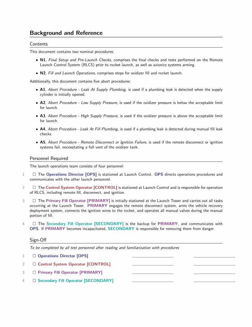
Background and Reference
Contents
This document contains two nominal procedures:
• N1, Final Setup and Pre-Launch Checks, comprises the final checks and tests performed on the RemoteLaunch Control System (RLCS) prior to rocket launch, as well as avionics systems arming.
• N2, Fill and Launch Operations, comprises steps for oxidizer fill and rocket launch.
Additionally, this document contains five abort procedures:
• A1, Abort Procedure - Leak At Supply Plumbing, is used if a plumbing leak is detected when the supplycylinder is initially opened.
• A2, Abort Procedure - Low Supply Pressure, is used if the oxidizer pressure is below the acceptable limitfor launch.
• A3, Abort Procedure - High Supply Pressure, is used if the oxidizer pressure is above the acceptable limitfor launch.
• A4, Abort Procedure - Leak At Fill Plumbing, is used if a plumbing leak is detected during manual fill leakchecks.
• A5, Abort Procedure - Remote Disconnect or Ignition Failure, is used if the remote disconnect or ignitionsystems fail, necessitating a full vent of the oxidizer tank.
Personnel Required
The launch operations team consists of four personnel:
1 � The Operations Director [OPS] is stationed at Launch Control. OPS directs operations procedures andcommunicates with the other launch personnel.
2 � The Control System Operator [CONTROL] is stationed at Launch Control and is responsible for operationof RLCS, including remote fill, disconnect, and ignition.
3 � The Primary Fill Operator [PRIMARY] is initially stationed at the Launch Tower and carries out all tasksoccurring at the Launch Tower. PRIMARY engages the remote disconnect system, arms the vehicle recoverydeployment system, connects the ignition wires to the rocket, and operates all manual valves during the manualportion of fill.
4 � The Secondary Fill Operator [SECONDARY] is the backup for PRIMARY, and communicates withOPS. If PRIMARY becomes incapacitated, SECONDARY is responsible for removing them from danger.
Sign-Off
To be completed by all test personnel after reading and familiarization with procedures
1 � Operations Director [OPS]
2 � Control System Operator [CONTROL]
3 � Primary Fill Operator [PRIMARY]
4 � Secondary Fill Operator [SECONDARY]
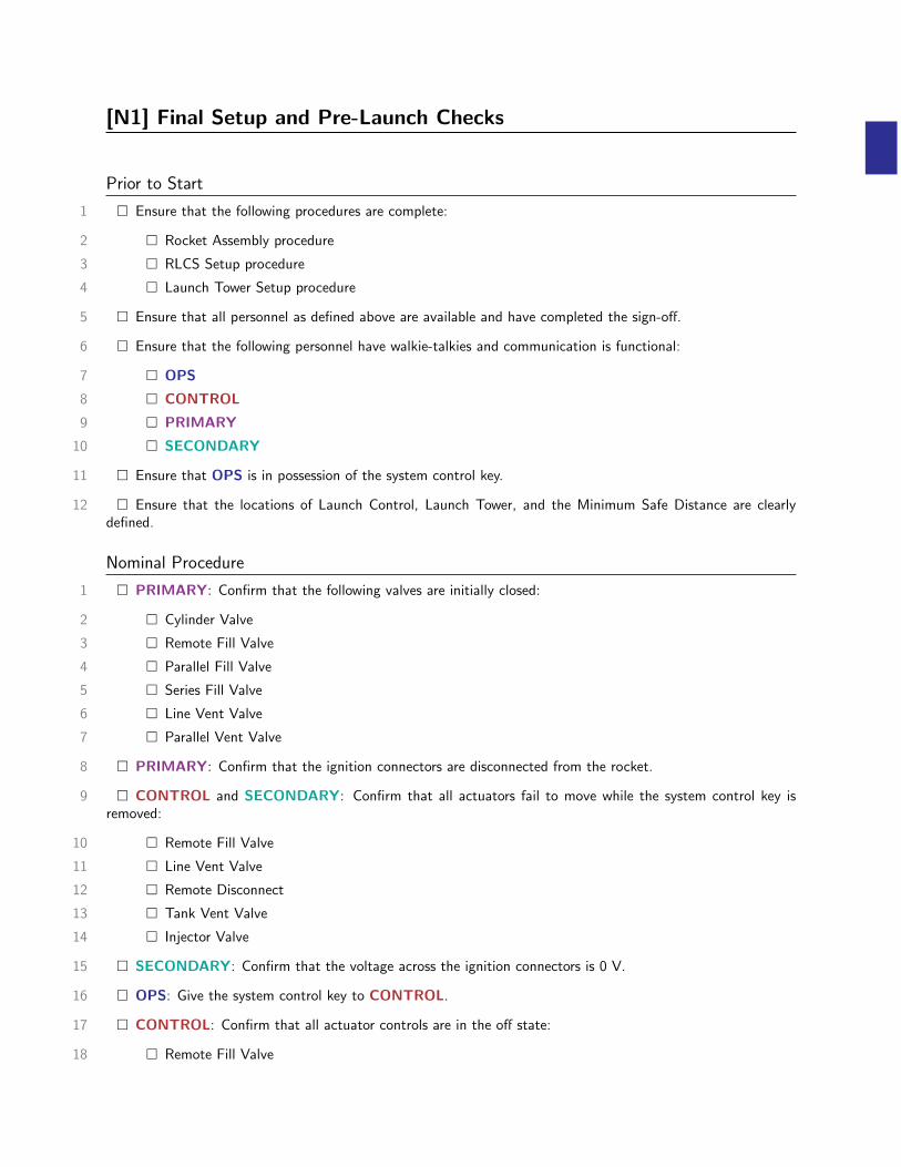
[N1] Final Setup and Pre-Launch Checks
Prior to Start
1 � Ensure that the following procedures are complete:
2 � Rocket Assembly procedure
3 � RLCS Setup procedure
4 � Launch Tower Setup procedure
5 � Ensure that all personnel as defined above are available and have completed the sign-off.
6 � Ensure that the following personnel have walkie-talkies and communication is functional:
7 � OPS
8 � CONTROL
9 � PRIMARY
10 � SECONDARY
11 � Ensure that OPS is in possession of the system control key.
12 � Ensure that the locations of Launch Control, Launch Tower, and the Minimum Safe Distance are clearlydefined.
Nominal Procedure
1 � PRIMARY: Confirm that the following valves are initially closed:
2 � Cylinder Valve
3 � Remote Fill Valve
4 � Parallel Fill Valve
5 � Series Fill Valve
6 � Line Vent Valve
7 � Parallel Vent Valve
8 � PRIMARY: Confirm that the ignition connectors are disconnected from the rocket.
9 � CONTROL and SECONDARY: Confirm that all actuators fail to move while the system control key isremoved:
10 � Remote Fill Valve
11 � Line Vent Valve
12 � Remote Disconnect
13 � Tank Vent Valve
14 � Injector Valve
15 � SECONDARY: Confirm that the voltage across the ignition connectors is 0 V.
16 � OPS: Give the system control key to CONTROL.
17 � CONTROL: Confirm that all actuator controls are in the off state:
18 � Remote Fill Valve
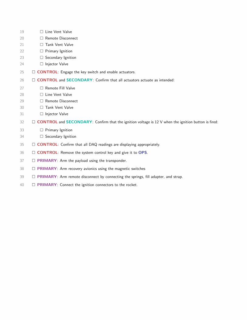
19 � Line Vent Valve
20 � Remote Disconnect
21 � Tank Vent Valve
22 � Primary Ignition
23 � Secondary Ignition
24 � Injector Valve
25 � CONTROL: Engage the key switch and enable actuators.
26 � CONTROL and SECONDARY: Confirm that all actuators actuate as intended:
27 � Remote Fill Valve
28 � Line Vent Valve
29 � Remote Disconnect
30 � Tank Vent Valve
31 � Injector Valve
32 � CONTROL and SECONDARY: Confirm that the ignition voltage is 12 V when the ignition button is fired:
33 � Primary Ignition
34 � Secondary Ignition
35 � CONTROL: Confirm that all DAQ readings are displaying appropriately.
36 � CONTROL: Remove the system control key and give it to OPS.
37 � PRIMARY: Arm the payload using the transponder.
38 � PRIMARY: Arm recovery avionics using the magnetic switches
39 � PRIMARY: Arm remote disconnect by connecting the springs, fill adapter, and strap.
40 � PRIMARY: Connect the ignition connectors to the rocket.
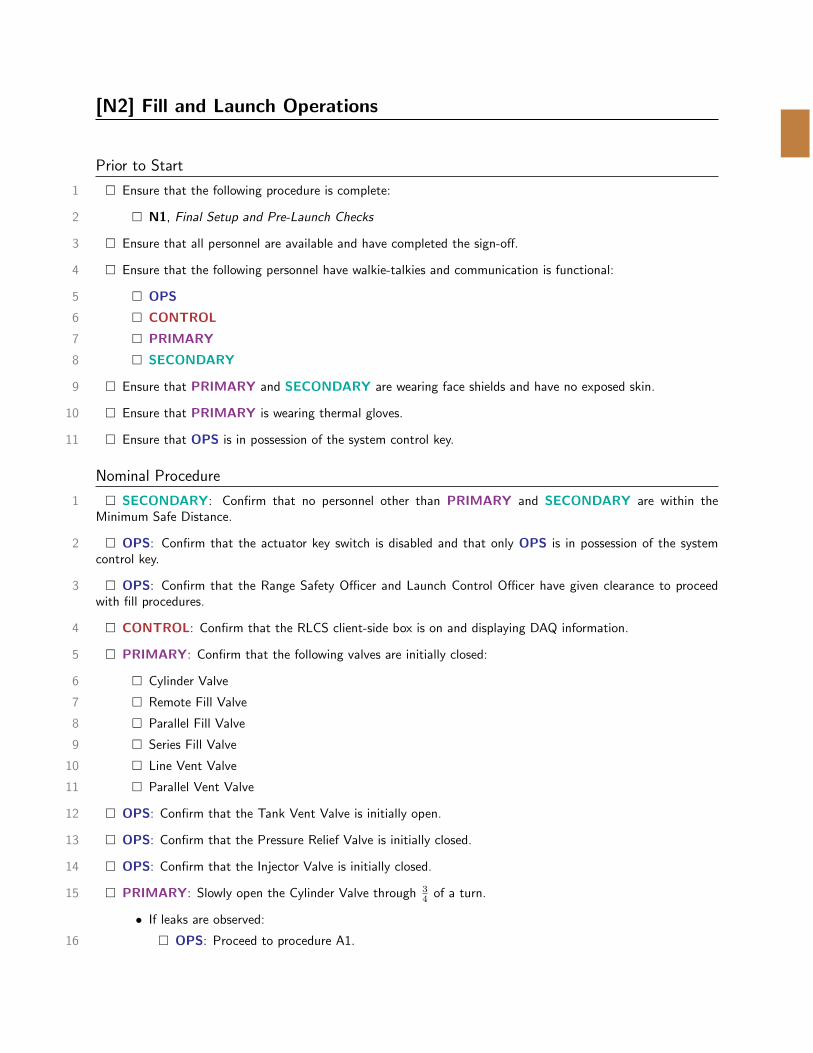
[N2] Fill and Launch Operations
Prior to Start
1 � Ensure that the following procedure is complete:
2 � N1, Final Setup and Pre-Launch Checks
3 � Ensure that all personnel are available and have completed the sign-off.
4 � Ensure that the following personnel have walkie-talkies and communication is functional:
5 � OPS
6 � CONTROL
7 � PRIMARY
8 � SECONDARY
9 � Ensure that PRIMARY and SECONDARY are wearing face shields and have no exposed skin.
10 � Ensure that PRIMARY is wearing thermal gloves.
11 � Ensure that OPS is in possession of the system control key.
Nominal Procedure
1 � SECONDARY: Confirm that no personnel other than PRIMARY and SECONDARY are within theMinimum Safe Distance.
2 � OPS: Confirm that the actuator key switch is disabled and that only OPS is in possession of the systemcontrol key.
3 � OPS: Confirm that the Range Safety Officer and Launch Control Officer have given clearance to proceedwith fill procedures.
4 � CONTROL: Confirm that the RLCS client-side box is on and displaying DAQ information.
5 � PRIMARY: Confirm that the following valves are initially closed:
6 � Cylinder Valve
7 � Remote Fill Valve
8 � Parallel Fill Valve
9 � Series Fill Valve
10 � Line Vent Valve
11 � Parallel Vent Valve
12 � OPS: Confirm that the Tank Vent Valve is initially open.
13 � OPS: Confirm that the Pressure Relief Valve is initially closed.
14 � OPS: Confirm that the Injector Valve is initially closed.
15 � PRIMARY: Slowly open the Cylinder Valve through 34 of a turn.
• If leaks are observed:
16 � OPS: Proceed to procedure A1.
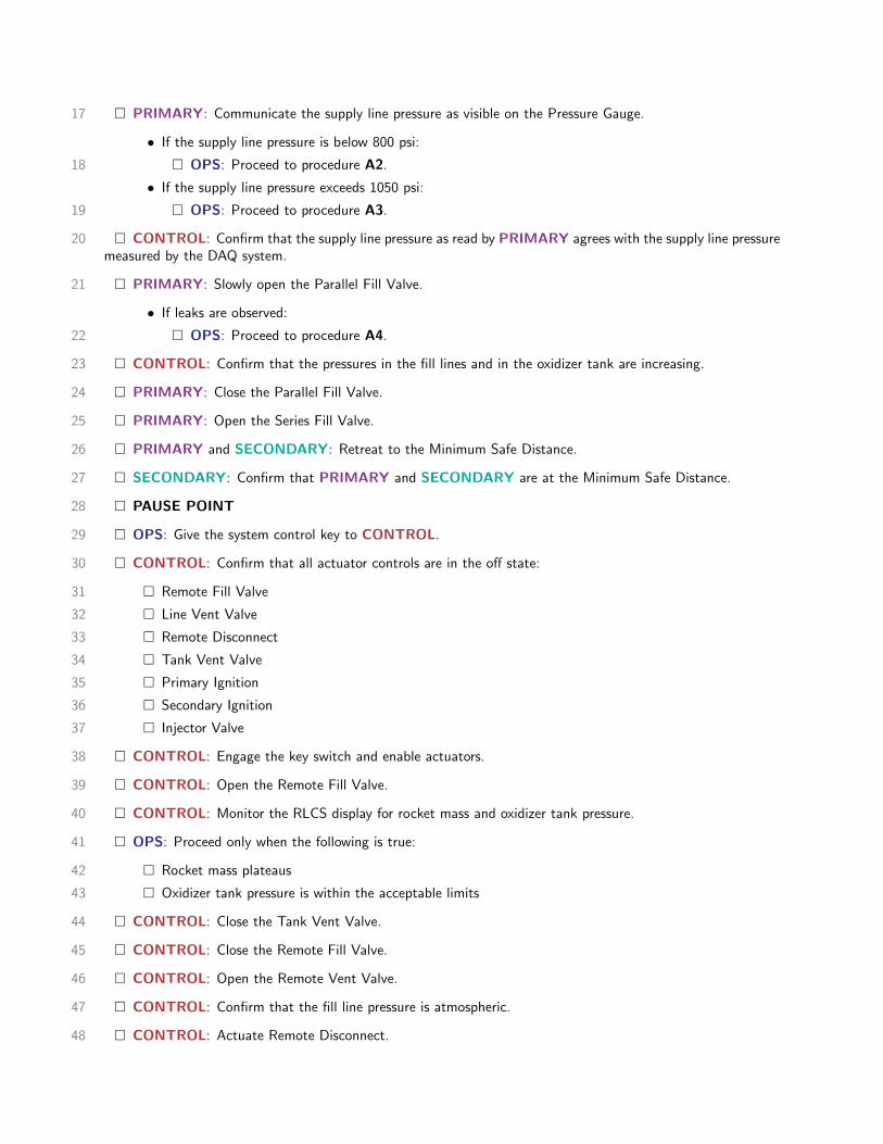
17 � PRIMARY: Communicate the supply line pressure as visible on the Pressure Gauge.
• If the supply line pressure is below 800 psi:
18 � OPS: Proceed to procedure A2.
• If the supply line pressure exceeds 1050 psi:
19 � OPS: Proceed to procedure A3.
20 � CONTROL: Confirm that the supply line pressure as read by PRIMARY agrees with the supply line pressuremeasured by the DAQ system.
21 � PRIMARY: Slowly open the Parallel Fill Valve.
• If leaks are observed:
22 � OPS: Proceed to procedure A4.
23 � CONTROL: Confirm that the pressures in the fill lines and in the oxidizer tank are increasing.
24 � PRIMARY: Close the Parallel Fill Valve.
25 � PRIMARY: Open the Series Fill Valve.
26 � PRIMARY and SECONDARY: Retreat to the Minimum Safe Distance.
27 � SECONDARY: Confirm that PRIMARY and SECONDARY are at the Minimum Safe Distance.
28 � PAUSE POINT
29 � OPS: Give the system control key to CONTROL.
30 � CONTROL: Confirm that all actuator controls are in the off state:
31 � Remote Fill Valve
32 � Line Vent Valve
33 � Remote Disconnect
34 � Tank Vent Valve
35 � Primary Ignition
36 � Secondary Ignition
37 � Injector Valve
38 � CONTROL: Engage the key switch and enable actuators.
39 � CONTROL: Open the Remote Fill Valve.
40 � CONTROL: Monitor the RLCS display for rocket mass and oxidizer tank pressure.
41 � OPS: Proceed only when the following is true:
42 � Rocket mass plateaus
43 � Oxidizer tank pressure is within the acceptable limits
44 � CONTROL: Close the Tank Vent Valve.
45 � CONTROL: Close the Remote Fill Valve.
46 � CONTROL: Open the Remote Vent Valve.
47 � CONTROL: Confirm that the fill line pressure is atmospheric.
48 � CONTROL: Actuate Remote Disconnect.
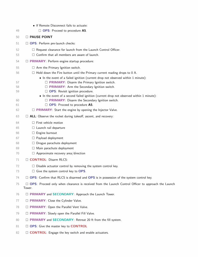
• If Remote Disconnect fails to actuate:
49 � OPS: Proceed to procedure A5.
50 � PAUSE POINT
51 � OPS: Perform pre-launch checks:
52 � Request clearance for launch from the Launch Control Officer.
53 � Confirm that all members are aware of launch.
54 � PRIMARY: Perform engine startup procedure:
55 � Arm the Primary Ignition switch.
56 � Hold down the Fire button until the Primary current reading drops to 0 A.
• In the event of a failed ignition (current drop not observed within 1 minute):
57 � PRIMARY: Disarm the Primary Ignition switch.
58 � PRIMARY: Arm the Secondary Ignition switch.
59 � OPS: Revisit ignition procedure.
• In the event of a second failed ignition (current drop not observed within 1 minute):
60 � PRIMARY: Disarm the Secondary Ignition switch.
61 � OPS: Proceed to procedure A5.
62 � PRIMARY: Start the engine by opening the Injector Valve.
63 � ALL: Observe the rocket during takeoff, ascent, and recovery:
64 � First vehicle motion
65 � Launch rail departure
66 � Engine burnout
67 � Payload deployment
68 � Drogue parachute deployment
69 � Main parachute deployment
70 � Approximate recovery area/direction
71 � CONTROL: Disarm RLCS:
72 � Disable actuator control by removing the system control key.
73 � Give the system control key to OPS.
74 � OPS: Confirm that RLCS is disarmed and OPS is in possession of the system control key.
75 � OPS: Proceed only when clearance is received from the Launch Control Officer to approach the LaunchTower.
76 � PRIMARY and SECONDARY: Approach the Launch Tower.
77 � PRIMARY: Close the Cylinder Valve.
78 � PRIMARY: Open the Parallel Vent Valve.
79 � PRIMARY: Slowly open the Parallel Fill Valve.
80 � PRIMARY and SECONDARY: Retreat 20 ft from the fill system.
81 � OPS: Give the master key to CONTROL
82 � CONTROL: Engage the key switch and enable actuators.

83 � CONTROL: Open the Remote Fill Valve.
84 � CONTROL: Confirm that the supply line pressure is atmospheric.
85 � PRIMARY: Disconnect the fill line from the supply cylinder.
86 � PRIMARY: Replace the cap on the nitrous oxide supply cylinder.
87 � OPS: Proceed with teardown and disassembly.
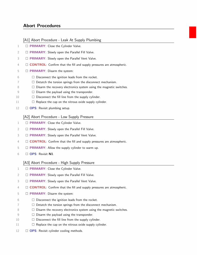
Abort Procedures
[A1] Abort Procedure - Leak At Supply Plumbing
1 � PRIMARY: Close the Cylinder Valve.
2 � PRIMARY: Slowly open the Parallel Fill Valve.
3 � PRIMARY: Slowly open the Parallel Vent Valve.
4 � CONTROL: Confirm that the fill and supply pressures are atmospheric.
5 � PRIMARY: Disarm the system:
6 � Disconnect the ignition leads from the rocket.
7 � Detatch the torsion springs from the disconnect mechanism.
8 � Disarm the recovery electronics system using the magnetic switches.
9 � Disarm the payload using the transponder.
10 � Disconnect the fill line from the supply cylinder.
11 � Replace the cap on the nitrous oxide supply cylinder.
12 � OPS: Revisit plumbing setup.
[A2] Abort Procedure - Low Supply Pressure
1 � PRIMARY: Close the Cylinder Valve.
2 � PRIMARY: Slowly open the Parallel Fill Valve.
3 � PRIMARY: Slowly open the Parallel Vent Valve.
4 � CONTROL: Confirm that the fill and supply pressures are atmospheric.
5 � PRIMARY: Allow the supply cylinder to warm up.
6 � OPS: Revisit N1.
[A3] Abort Procedure - High Supply Pressure
1 � PRIMARY: Close the Cylinder Valve.
2 � PRIMARY: Slowly open the Parallel Fill Valve.
3 � PRIMARY: Slowly open the Parallel Vent Valve.
4 � CONTROL: Confirm that the fill and supply pressures are atmospheric.
5 � PRIMARY: Disarm the system:
6 � Disconnect the ignition leads from the rocket.
7 � Detatch the torsion springs from the disconnect mechanism.
8 � Disarm the recovery electronics system using the magnetic switches.
9 � Disarm the payload using the transponder.
10 � Disconnect the fill line from the supply cylinder.
11 � Replace the cap on the nitrous oxide supply cylinder.
12 � OPS: Revisit cylinder cooling methods.
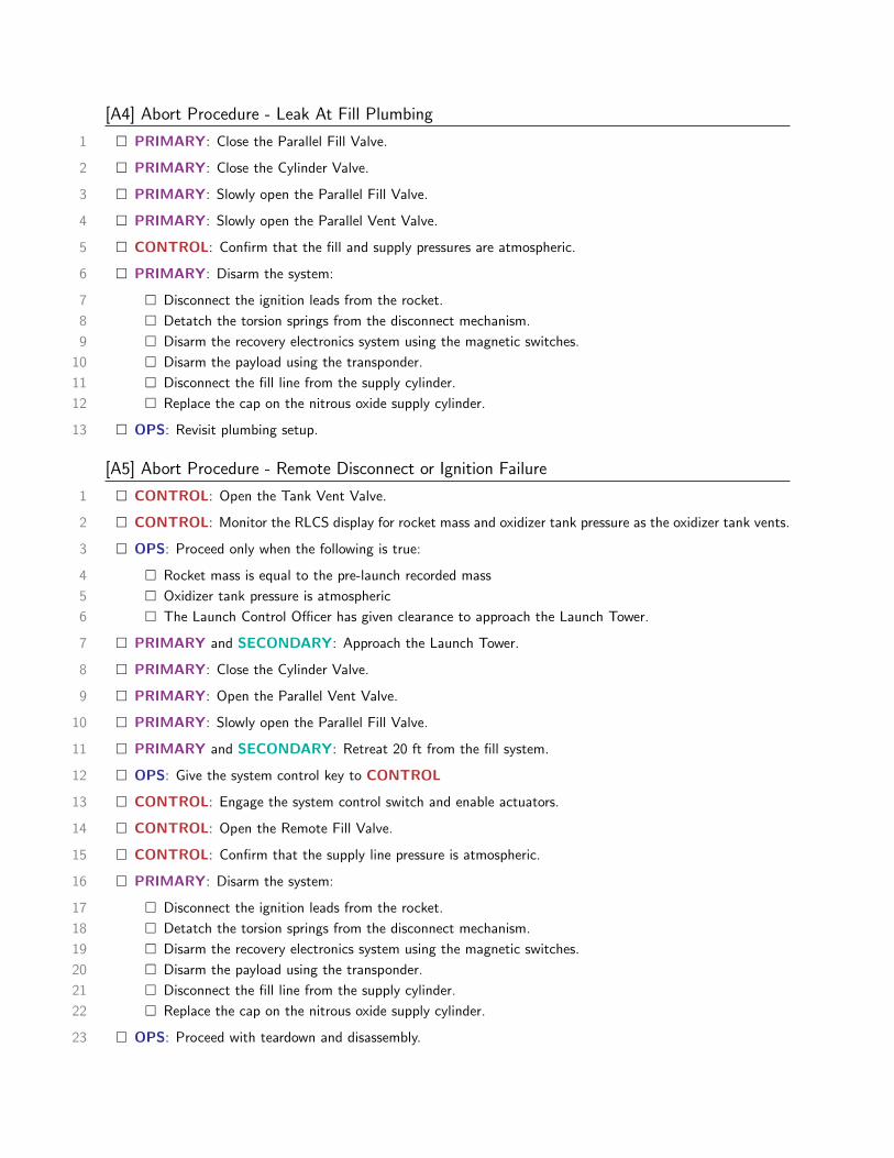
[A4] Abort Procedure - Leak At Fill Plumbing
1 � PRIMARY: Close the Parallel Fill Valve.
2 � PRIMARY: Close the Cylinder Valve.
3 � PRIMARY: Slowly open the Parallel Fill Valve.
4 � PRIMARY: Slowly open the Parallel Vent Valve.
5 � CONTROL: Confirm that the fill and supply pressures are atmospheric.
6 � PRIMARY: Disarm the system:
7 � Disconnect the ignition leads from the rocket.
8 � Detatch the torsion springs from the disconnect mechanism.
9 � Disarm the recovery electronics system using the magnetic switches.
10 � Disarm the payload using the transponder.
11 � Disconnect the fill line from the supply cylinder.
12 � Replace the cap on the nitrous oxide supply cylinder.
13 � OPS: Revisit plumbing setup.
[A5] Abort Procedure - Remote Disconnect or Ignition Failure
1 � CONTROL: Open the Tank Vent Valve.
2 � CONTROL: Monitor the RLCS display for rocket mass and oxidizer tank pressure as the oxidizer tank vents.
3 � OPS: Proceed only when the following is true:
4 � Rocket mass is equal to the pre-launch recorded mass
5 � Oxidizer tank pressure is atmospheric
6 � The Launch Control Officer has given clearance to approach the Launch Tower.
7 � PRIMARY and SECONDARY: Approach the Launch Tower.
8 � PRIMARY: Close the Cylinder Valve.
9 � PRIMARY: Open the Parallel Vent Valve.
10 � PRIMARY: Slowly open the Parallel Fill Valve.
11 � PRIMARY and SECONDARY: Retreat 20 ft from the fill system.
12 � OPS: Give the system control key to CONTROL
13 � CONTROL: Engage the system control switch and enable actuators.
14 � CONTROL: Open the Remote Fill Valve.
15 � CONTROL: Confirm that the supply line pressure is atmospheric.
16 � PRIMARY: Disarm the system:
17 � Disconnect the ignition leads from the rocket.
18 � Detatch the torsion springs from the disconnect mechanism.
19 � Disarm the recovery electronics system using the magnetic switches.
20 � Disarm the payload using the transponder.
21 � Disconnect the fill line from the supply cylinder.
22 � Replace the cap on the nitrous oxide supply cylinder.
23 � OPS: Proceed with teardown and disassembly.

47
Experimental Sounding Rocket Association
Engineering Drawings Appendix
The following pages contain engineering drawings of significant UXO components and assemblies.
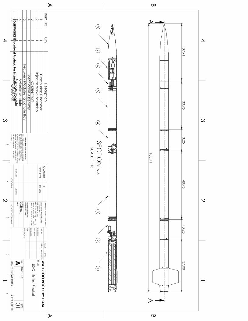
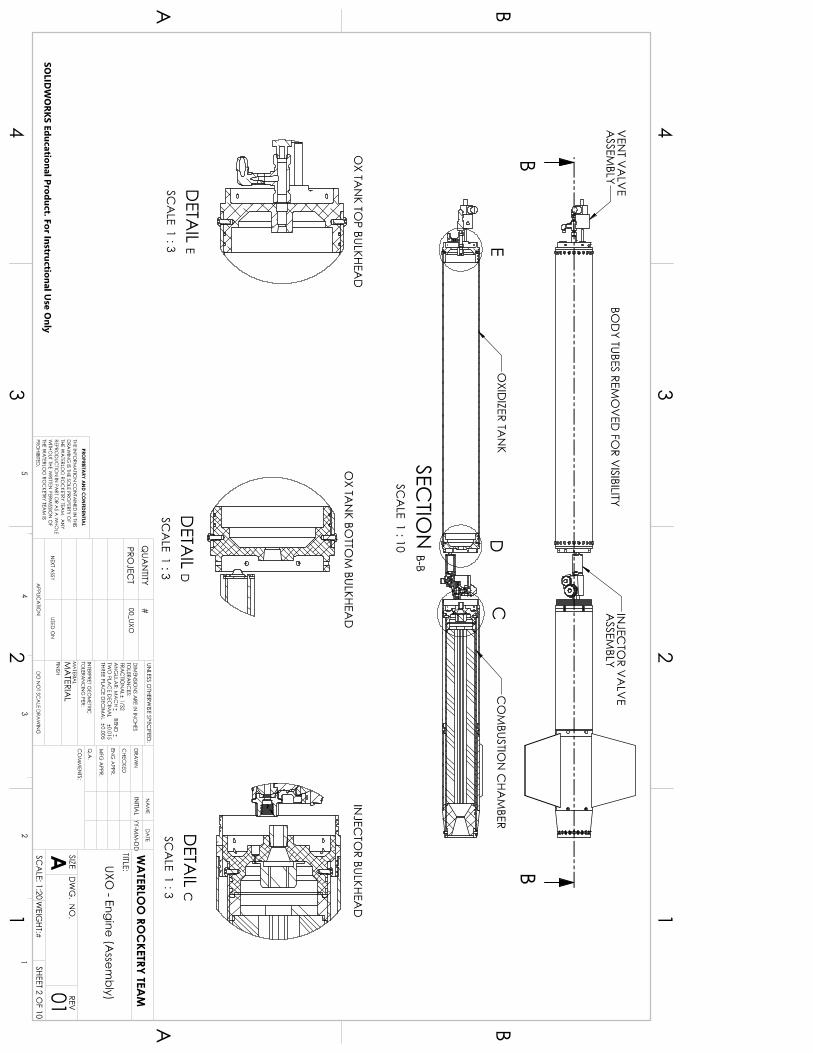
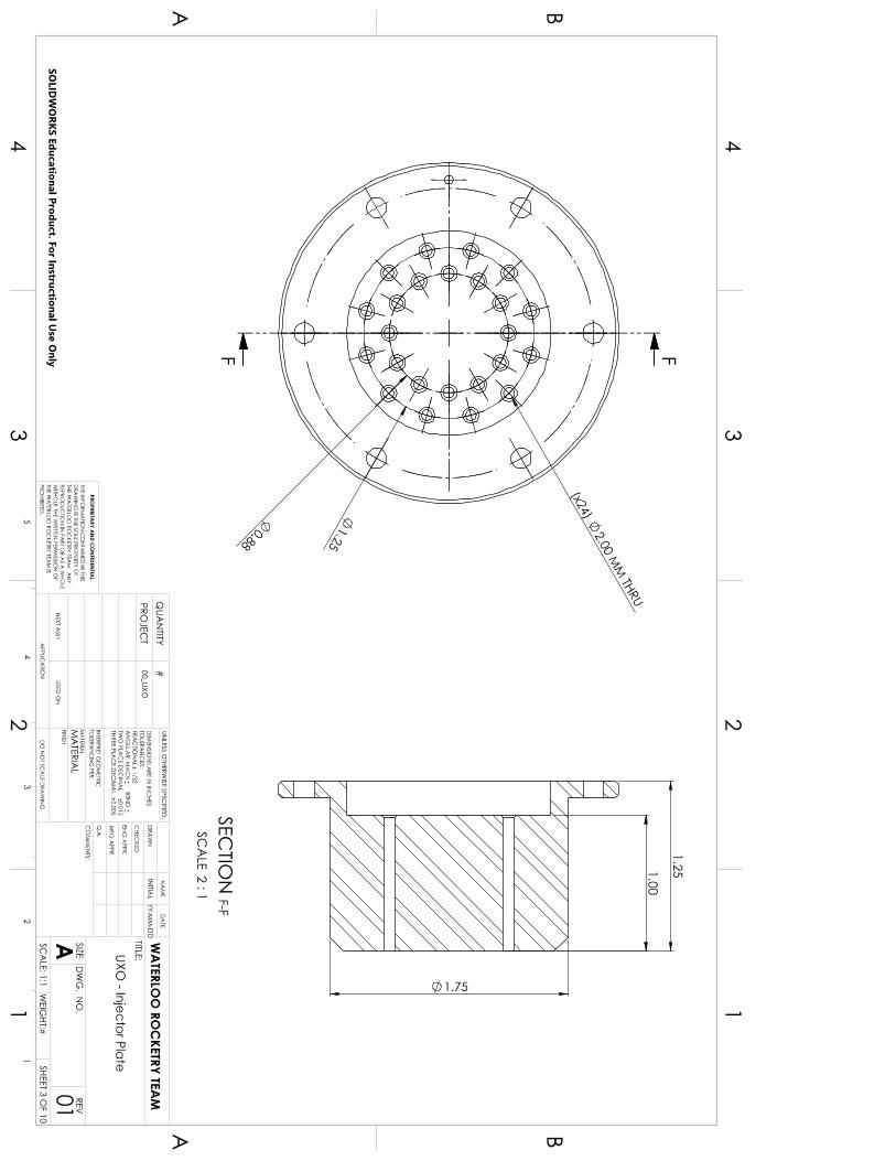
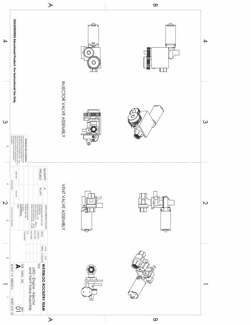
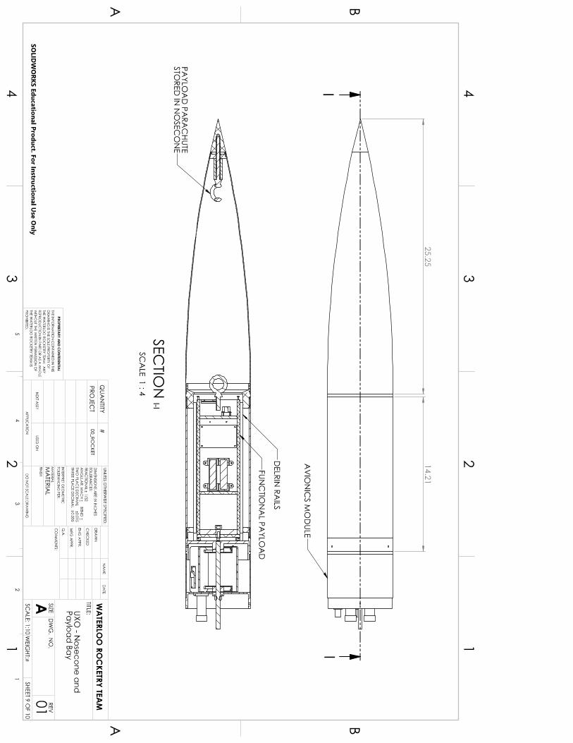
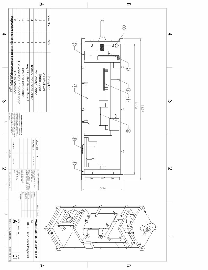
58
Experimental Sounding Rocket Association
Acknowledgments
The team would like to thank our advisors, who have provided invaluable advice and guidance throughout our
development. Specifically, we would like to thank Dr. Andrew J.B. Milne, Dan Steinhaur, Adam Trumpour, Dr. Jean-
Pierre Hickey, and Andy Phillips. We would also like to acknowledge the contributions of all of our sponsors. Without
their support, we would not be able to continue providing valuable learning opportunities for our team members. In
particular, Stein Industries has made and continues to make significant investments in our team’s success. Stein
Industries and Dan Steinhaur deserve special acknowledgement for the many years of support that they have provided
to our team.
Finally, the team wishes to thank all of the team alumni who have paved the way for the current team members.
The team owes much to the dedication of past members.
References 1Waxman, B. S. “An Investigation of Injectors for use with High Vapor Pressure Propellants with Applications to Hybrid
Rockets,” Ph.D. Dissertation, Department of Aeronautics & Astronautics, Stanfort Univ., Stanford, CA, 2014.