Embed Size (px)
Citation preview
For the Wiley Encyclopedia of Electrical and Electronics Engineering
Underwater Acoustic Communication
Milica Stojanovic
Electrical and Computer Engineering Department
Northeastern University
Boston, MA 02115
index terms: acoustic; communications; coherent; equalization; channel estimation; phase
synchronizations; multipath; Doppler; sparse channels; diversity combining; beamform-
ing; multiuser detection; interference suppression; time-reversal; multi-input-multi-output
(MIMO) processing; multi-carrier modulation; OFDM; adaptive modulation; underwater
networks.
The need for underwater wireless communications exists in applications such as remote con-
trol in off-shore oil and gas industry, pollution and climate monitoring in environmental sys-
tems, defense, collection of scientific data recorded at ocean-bottom stations and unmanned
underwater vehicles, speech transmission between divers, and mapping of the ocean floor for
detection of objects and discovery of new resources. Wireless underwater communications
can be established by transmission of acoustic waves. The underwater acoustic communica-
tion channels, however, have limited bandwidth, and often cause signal dispersion in time
and frequency [1], [2], [3]. Despite these limitations, underwater acoustic communications
are a rapidly growing field of research and engineering.
Acoustic waves are not the only means for wireless communication underwater, but they are
the only ones that can travel over longer distances. Radio waves that will propagate over
longer distance through conductive sea water are the extra low frequency ones (30 Hz-300 Hz)
which require large antennae and high transmitter powers [4], while higher-frequency signals
will propagate only over very short distances (few meters at 10 kHz) [5]. Optical waves
propagate best in the blue-green region, but in addition to attenuation, they are affected by
scattering, and are limited to distances on the order of a hundred meters [6]. Narrow laser
beams are power-efficient but require high pointing precision, while simple light-emitting
diodes are not as power-efficient. Thus, acoustic waves remain the single best solution for
communicating underwater, in applications where tethering is not acceptable and anything
but a very short distance is to be covered.
Sound propagates as a pressure wave, and it can easily travel over kilometers, or even hun-
dreds of kilometers, but to cover a longer distance, a lower frequency has to be used. In
general, acoustic communications are confined to bandwidths that are low compared to those
used for terrestrial radio communications. Acoustic modems that are in use today typically
operate in bandwidths on the order of a few kHz, at a comparably low center frequency (e.g.
5 kHz centered at 10 kHz) [7]. While such frequencies will cover distances on the order of
a kilometer, acoustic frequencies in the 100 kHz region can be used for shorter distances,
while frequencies below a kHz are used for longer distances. Underwater acoustic communi-
cation over basin scales (several thousand kilometers) can be established in a single hop as
1
well; however, the attendant bandwidth will be only on the order of 10 Hz [8]. Horizontal
transmission is notoriously more difficult due to the multipath propagation, while vertical
channels exhibit less distortion [9]. Frequency-dependent attenuation, multipath propaga-
tion, and low speed of sound (about 1500 m/s) which results in a severe Doppler effect, make
the underwater acoustic channel one of the most challenging communication media.
The idea of sending and receiving information underwater is traced back all the way to
the time of Leonardo Da Vinci, who is quoted for discovering the possibility to detect a
distant ship by listening on a long tube submerged under the sea. In the modern sense of
the word, underwater communications began to develop during the second World War, for
military purposes. One of the first underwater communication systems was an underwater
telephone, developed in 1945 in the United States for communicating with submarines [10].
This device used a single-sideband (SSB) suppressed carrier amplitude modulation in the 8
kHz-11 kHz frequency range, and it was capable of sending acoustic signals over distances
of several kilometers. However, it was not until the development of VLSI technology that a
new generation of underwater acoustic communication systems began to emerge. With the
availability of compact digital signal processors (DSPs) with their moderate power require-
ments, it became possible for the first time to implement complex signal processing and data
compression algorithms at the submerged ends of an underwater communication link.
During the past two decades, significant advancements have been made in the develop-
ment of underwater acoustic communication systems in terms of their operational range and
data throughput (overview articles [12]-[15] document the history of these developments).
Acoustically controlled robots have been used to replace divers in performing maintenance
of submerged platforms [16]; high-quality image transmission from the bottom of deepest
ocean trenches (6500 km) to a surface ship was established [17], [18]; and data telemetry
over horizontal distances in excess of 200 kilometers was demonstrated [19], [20].
As efficient communication systems are developing, the scope of their applications continues
to grow, and so do the requirements on the system performance. Many of the developing
applications, both commercial and military, are calling for real-time communication with
submarines and autonomous, or unmanned underwater vehicles (AUVs, UUVs). Setting the
2
underwater vehicles free from cables will enable them to move freely and refine their range of
operation. The emerging communication scenario in which the modern underwater acoustic
systems will operate is that of an underwater data network consisting of both stationary and
mobile nodes [15]. This network is envisaged to provide exchange of data, such as control,
telemetry and eventually video signals, between many network nodes. The network nodes,
located on underwater moorings, robots and vehicles, will be equipped with various sensors,
sonars and video cameras. A remote user will be able to access the network via a radio link
to a central node based on a surface station.
Towards achieving these goals, current research and development efforts are focusing on the
development of efficient communications and signal processing algorithms, design of efficient
modulation and coding schemes, and techniques for mobile underwater communications.
In addition, multiple access communication methods are being developed for underwater
acoustic networks, and network protocols are being designed for long propagation delays
and strict power requirements encountered in the underwater environment. Finally, data
compression algorithms suitable for low-contrast underwater images, and related image and
video processing methods are expected to enable their near real-time transmission through
band-limited underwater acoustic channels.
System requirements
The achievable data throughput, and the reliability of an underwater acoustic communication
system, as measured by the bit-error rate, vary from system to system, but are always
subject to bandwidth limitations of the ocean channel. Unlike in the majority of other
communication media, the use of underwater acoustic resources has not been regulated yet
by standards, except for those that protect the marine life.
In the existing systems, there are usually four kinds of signals that are transmitted: control,
telemetry, speech and video signals.
Control signals include navigation, status information, and various on/off commands for
underwater robots, vehicles and submerged instrumentation such as pipeline valves or deep
ocean moorings. The data rates up to about 1 kilobit per second (kbps) are sufficient for
3
these operations, but very low bit-error rates may be required.
Telemetry data is collected by submerged acoustic instruments such as hydrophones, seis-
mometers, sonars, current-meters, chemical sensors, and it also may include low rate image
data. Data rates on the order of one to several tens of kbps are required for these applica-
tions. The reliability requirements are not so stringent as for the command signals, and a
probability of bit error of 10−3− 10−4 is acceptable for many of the applications.
Speech signals are transmitted between divers and a surface station or among divers. While
some of the existing, commercially available diver communication systems still use analog
communications, based on single-sideband modulation of the 3 kHz audio signal, research is
advancing in the area of synthetic speech transmission for divers, as digital transmission is
expected to provide better reliability. Transmission of digitized speech by linear predictive
coding (LPC) methods requires rates on the order of several kbps to achieve close-to-toll
quality. The bit error rate tolerance of about 10−2 makes it a viable technology for poor
quality band-limited underwater channels [21].
Video transmission over underwater acoustic channels requires extremely high compression
ratios if an acceptable frame transmission rate is to be achieved. Fortunately, underwater
images exhibit low contrast and detail, and preserve satisfactory quality if compressed even
to 2 bits per pixel. Compression methods, such as the JPEG (Joint Photographic Experts
Group) standard discrete cosine transform, have been used to transmit 256 × 256 pixel still
images with 2 bits per pixel, at transmission rates of about one frame per 10 second [17].
Further reduction of the required transmission rate seems to be possible by using dedicated
compression algorithms, e.g., the discrete wavelet transform [22]. Video transmission appears
possible using the modern compression techniques of the MPEG-4 type, which can operate at
bit rates below 64 kbps with moderate detection performance as images will have satisfactory
quality at bit error rates on the order of 10−3− 10−4 [23].
4
Channel characteristics
Sound propagation underwater is primarily determined by transmission loss, noise, rever-
beration, and temporal and spatial variability of the channel. Transmission loss and noise
are the principal factors determining the available bandwidth, range and signal-to-noise ra-
tio. Time-varying multipath influences signal design and processing, which determine the
information throughput and communication system performance.
Range and bandwidth
Transmission loss is caused by energy spreading and sound absorption. While the energy
spreading loss depends only on the propagation distance, the absorption loss increases not
only with range but also with frequency, thus setting the limit on the available bandwidth.
In addition to the nominal transmission loss, link condition is largely influenced by the
spatial variability of the underwater acoustic channel. Spatial variability is a consequence
of the waveguide nature of the channel, which results in such phenomena as formation of
shadow zones. Transmission loss at a particular location can be predicted by many of the
propagation modeling techniques [1] with various degrees of accuracy. Spatial dependence
of transmission loss imposes particularly severe problems for communication with moving
sources or receivers.
Noise observed in the ocean consists of man-made noise and ambient noise. In deep ocean,
ambient noise dominates, while near shores, and in the presence of shipping activity, man-
made noise significantly increases the noise level. Unlike the man-made noise, most of the
ambient noise sources can be described as having a continuous spectrum and Gaussian
statistics [1]. As a first approximation, the ambient noise power spectral density is commonly
assumed to decay at about 20 dB/decade, both in shallow and deep water, over frequencies
which are of interest to communication systems design. The exception are biological sources
of noise, such as snapping shrimp which lives only in certain geographical areas and produces
impulsive noise within the range of frequencies used by a typical communication system [24].
Frequency-dependent transmission loss and noise determine the relationship between the
5
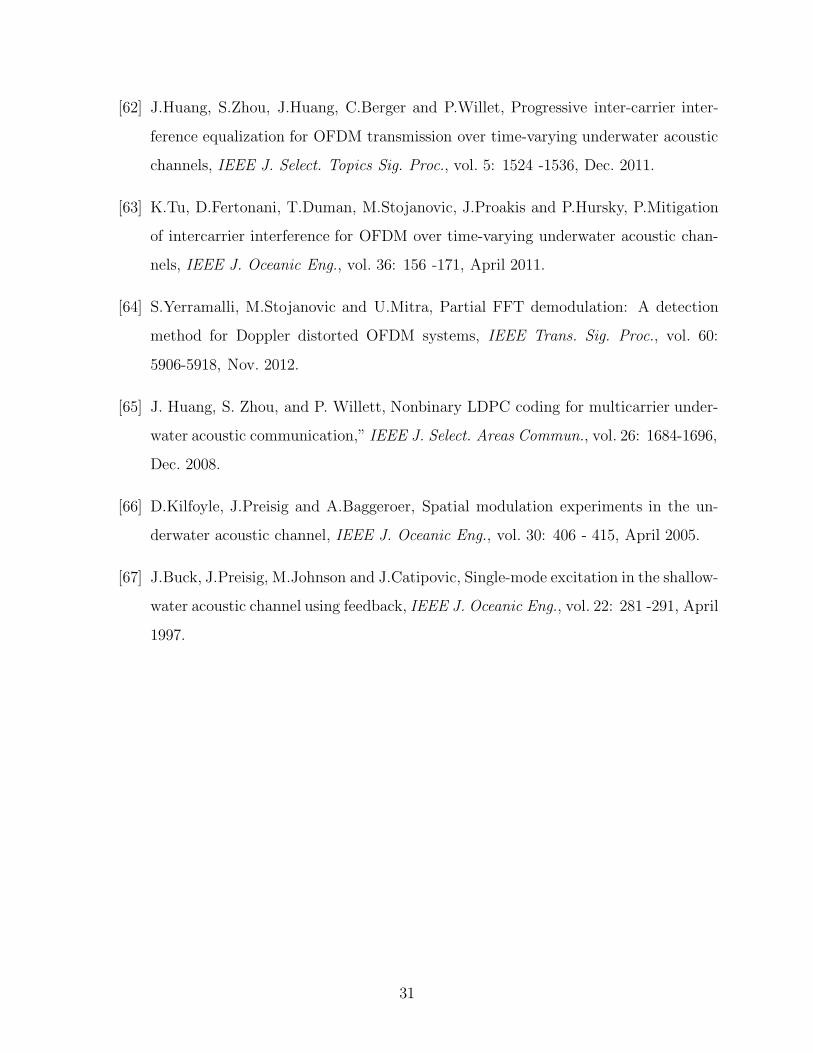
available range, bandwidth and SNR at the receiver input. This dependence is illustrated in
Fig.1, which shows the frequency dependent portion of SNR for several transmission ranges.
(The SNR is evaluated assuming spherical spreading, absorption according to Thorp [1]
and a 20 dB/dec decay of the noise power spectral density.) Evidently, this dependence
influences the choice of a carrier frequency for the desired transmission range. In addition,
it determines the relationship between the available range and frequency band. Underwater
acoustic communication links can be classified according to range as very long, long, medium,
short and very short links. For a long-range system, operating over 10-100 km, the bandwidth
is limited to few kHz (for a very long distance on the order of 1000 km, the available
bandwidth falls below one kHz). A medium-range system operating over 1-10 km has a
bandwidth on the order of 10 kHz, while only at very short ranges below about 100 m, more
than a hundred kHz of bandwidth may be available.
Within this limited bandwidth, the signal is subject to multipath propagation through a
channel whose characteristics vary with time and are highly dependent on the location of the
transmitter and receiver. The multipath structure depends on the link configuration, which
is primarily designated as vertical or horizontal. While vertical channels exhibit little time-
dispersion, horizontal channels may have extremely long multipath spreads. Most notable
in the long- and medium-range channels, multipath propagation causes severe degradation
of the acoustic communication signals. Combating the underwater multipath to achieve a
high data throughput is without exception considered to be the most challenging task of an
underwater acoustic communication system.
Multipath
In a digital communication system which uses a single carrier, multipath propagation causes
intersymbol interference (ISI), and an important figure of merit is multipath spread in terms
of symbol intervals. While typical multipath spreads in the commonly used radio channels
are on the order of several symbol intervals, in horizontal underwater acoustic channels they
increase to several tens, or a hundred of symbol intervals for moderate to high data rates.
For example, a commonly encountered multipath spread of 10 ms in a medium-range shallow
6
water channel, causes the ISI to extend over 100 symbols if the system is operating at a rate of
10 kilosymbols per second (ksps). Multi-carrier systems avoid this problem by transmitting
in parallel on many carriers, each occupying a narrow sub-band, whose width is kept well
below the coherence frequency (inverse of the multipath spread).
The mechanisms of multipath formation in the ocean are different in deep and shallow
water, and also depend on the frequency and range of transmission. Understanding of these
mechanisms is based on the theory and models of sound propagation. Depending on the
system location, there are several typical ways of multipath propagation. It is mostly the
water depth that determines the type of propagation. The definition of shallow and deep
water is not a strict one, but usually implies the region of continental shelves, with depth
less than about 100 m, and the region past the continental shelves, where the water gets
deeper. Two fundamental mechanisms of multipath formation are reflection at boundaries
(bottom, surface and any objects in the water), and ray bending (rays of sound always bend
towards regions of lower propagation speed). If the water is shallow, propagation will occur
in surface-bottom bounces in addition to a possible direct path. If the water is deep, as
in the regions past the continental shelves, the sound channel may form by bending of the
rays toward the location where the sound speed reaches its minimum, called the axis of
the deep sound channel. Because there is no loss due to reflections, sound can travel in
this way over several thousands of kilometers. Alternatively, the rays bending upwards may
reach the surface focusing in one point where they are reflected, and the process is repeated
periodically. The region between two focusing points on the surface is called a convergence
zone, and its typical length is 60 km-100 km.
The geometry of multipath propagation and its spatial dependence are important for com-
munication systems which use array processing to suppress multipath (e.g. [25]). The design
of such systems is often accompanied by the use of a propagation model for predicting the
multipath configuration. Ray theory and the theory of normal modes provide basis for such
propagation modeling.
7
Time-variation
Associated with each of the deterministic propagation paths (macro-multipaths), which can
be modeled accurately, are random signal fluctuations (micro-multipath), which account for
the time-variability of the channel response. Some of the random fluctuations can be modeled
statistically [1],[2]. These fluctuations include surface scattering due to waves, which is the
most important contributor to the overall time-variability of the shallow water channel. In
deep water, in addition to surface scattering, internal waves contribute to the time-variation
of the signal propagating along each of deterministic paths.
Surface scattering is caused by the roughness of the ocean surface. If the ocean were calm,
a signal incident on the surface would be reflected almost perfectly, with the only distortion
being a phase shift of π. However, wind-driven waves act as the displacement of the reflection
point, resulting in signal dispersion. Vertical displacement of the surface can be well modeled
as a zero-mean Gaussian random variable, whose power spectrum is completely characterized
by the wind speed [1]. Motion of the reflection point results in frequency spreading of the
surface-reflected signal, significantly larger than that caused by many other phenomena.
Doppler spread of a signal component of frequency f caused by a single surface-reflection
occurring at an incidence angle θ is 0.0175(f/c)w3/2 cos θ where c is the speed of sound,
nominally taken to be 1500 m/s, and w is the wind speed in m/s [1]. A moderate wind speed
is on the order of 10 m/s. Highest Doppler spreads are most likely to be found in short range
links, which use relatively high frequencies. For longer ranges, at which lower frequencies are
used, the Doppler spread will be lower; however, multipath spread will increase as there will
be more significant propagation paths. The exact values of multipath and Doppler spreads
depend on the geometry of multipath on a particular link. Nevertheless, it can be said that
the channel spread factor, i.e. the product of the Doppler spread and the multipath spread,
can in general be expected to decrease with range.
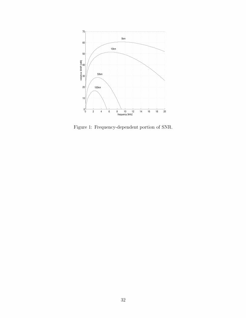
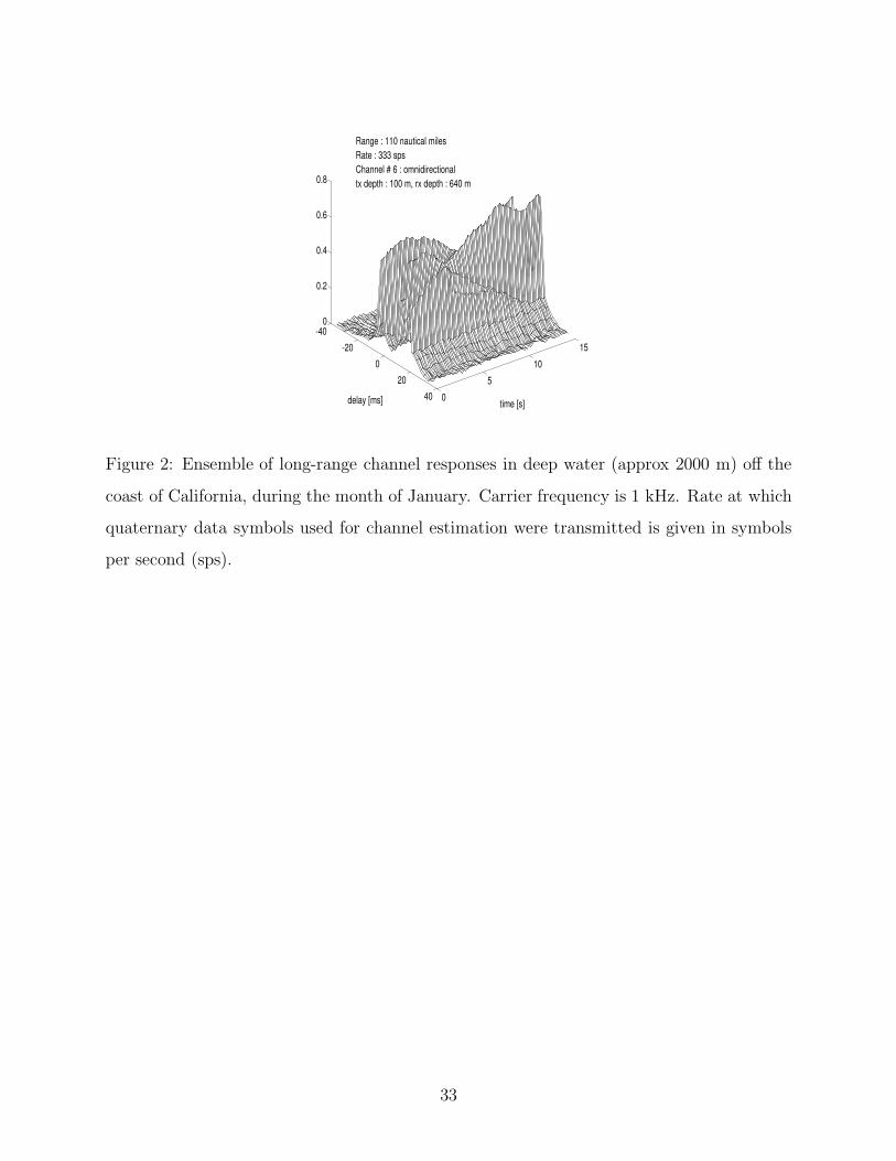
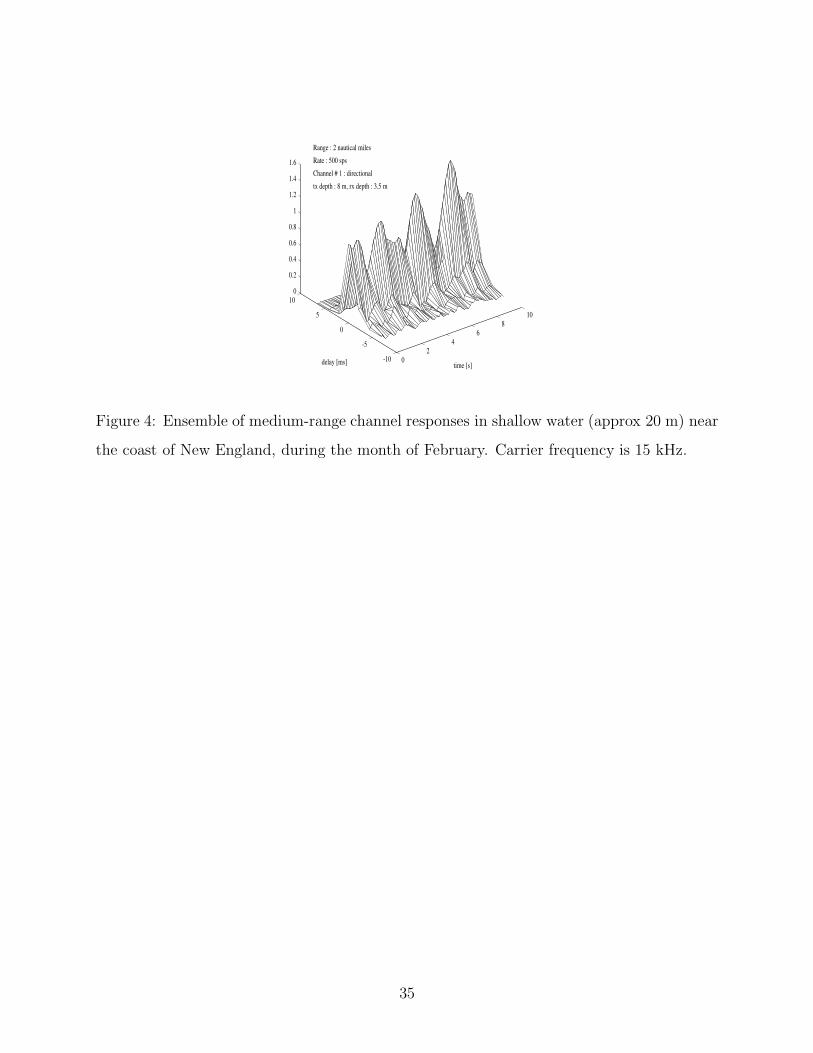
As an example, Figs.2-4 each show an ensemble of channel impulse responses, observed as
functions of delay over an interval of time. These figures describe channel responses obtained
at three fundamentally different locations with different mechanisms of multipath formation.
Fig.2 shows the impulse responses recorded in deep water of the Pacific ocean, off the coast
8
of California. In this channel, propagation occurs over three convergence zones, which span
110 nautical miles. At each fixed time instant, the figure shows a realization of the channel
impulse response magnitude as a function of delay. Looking at one channel response reveals
that two or more signals arrive at the receiver at any given time. The multipath delay spread
in this channel is on the order of 20 ms. The multiple arrivals have comparable energy, thus
causing strong ISI. The amplitudes and phases of distinct arrivals may vary independently in
time. Along the time axis, variation of the channel response is observed for each given delay.
In this example, significant variation occurs over the shown 15 second interval. This channel
does not have a well-defined principal, or strongest arrival, as evidenced by the fact that the
maximum amplitude does not always occur at the same delay. The channel responses shown
in Figs.2-4 are obtained by adaptive channel estimation techniques. In particular, a recursive
least-squares algorithm is applied to 4-PSK signals transmitted over the channels at rates
indicated in the figures. Fig.3 shows the impulse responses obtained in shallow water of the
Atlantic ocean continental shelf, off the coast of New England, over a long distance of 48
nautical miles. This example shows a channel with a well-defined principal arrival, followed
by multipath of lower energy. The extent of multipath is up to 50 ms. It is worth noting that
even though the extended multipath may appear to have negligible energy, its contribution
to the overall ISI cannot be neglected. This channel shows a slower time-variation than
the one observed in Fig.2. In contrast, Fig.4 provides an example of a rapidly time-varying
channel. These response were recorded in the shallow water of Buzzards Bay near the coast
of New England, over a distance of 2 nautical miles. Of the three examples shown, this
channel demonstrates the fastest time-variation, which is typical of a medium-range shallow
water environment.
The factor that determines the performance of a digital communication system on a frequency-
spread channel is the Doppler spread normalized by the symbol rate. In underwater acoustic
channels, the normalized Doppler spread can approach values as high as 10−2. The im-
plications that the time-varying multipath bears on the communication system design are
twofold. On the one hand, signaling at a high rate causes many adjacent symbols to in-
terfere at the receiver, and requires sophisticated processing to compensate for the ISI. On
the other hand, as pulse duration becomes shorter, channel variation over a single symbol
9
interval becomes slower. This allows an adaptive receiver to efficiently track the channel
on a symbol-to-symbol basis, provided, of course, a method for dealing with the resulting
time-dispersion. Hence, time-varying multipath causes a trade-off in the choice of signaling
rate for a given channel. Experimental results obtained on a rapidly varying shallow water
channel [26] demonstrate these observations.
While there exists a vast knowledge of both deterministic and statistical modeling of sound
propagation underwater, the use of this knowledge in modeling of communication channels
has only recently begun to receive more attention (e.g., [27], [28],[29]). Modeling of the slower
variations of the locally-averaged received signal power (large-scale modeling) offers some
evidence in support of a log-normal model for the channel gain [30], [31],[29]. Experimental
studies of the small scale fading have offered evidence to Rician [29, 30, 32] as well as Rayleigh
phenomena [33]. Combining the effects of large- and small-scale fading leads to a mixture
of log-normal and Rician distributions, which can be approximated in closed form by the
compound K-distribution [34]. As far as the time-correlation properties are concerned, it is
generally understood that coherence times on the order of 100 ms can be assumed for a
general-purpose design.
In addition to the inherent random phenomena, motion of the transmitter, receiver, or a
reflection point along the signal path causes the path distances to vary with time. The
resulting Doppler effect is evident as time compression/dilation of the signal, which causes
frequency shifting and bandwidth spreading/shrinking. The magnitude of the Doppler effect
is proportional to the ratio v/c of the relative transmitter-receiver velocity to the speed
of sound. Because the speed of sound is very low as compared to the speed of electro-
magnetic waves, motion-induced Doppler distortion of an acoustic signal can be extreme.
AUVs move at speeds that are on the order of a few m/s, but even without intentional
motion, underwater instruments are subject to drifting with waves, currents and tides, which
may occur at comparable velocities. The resulting v/c ratio is on the order of 10−3, which,
compared to the land-mobile radio communication systems where this value os on the order of
10−7, presents a striking difference. Even after proper initial synchronization and resampling
of the signal, the residual Doppler frequency offset presents a challenge to mobile acoustic
10
communications.
Knowledge of statistical channel models has proven to be useful in the design and analysis of
land-mobile radio systems, and first attempts at modeling the distribution and the correlation
functions of the underwater acoustic mobile systems have been made [29]. More is certainly
to come on this topics, and on related issues in channel coherence in time, frequency, and
space.
System design
To overcome the difficulties of time-varying multipath dispersion, the initial design of under-
water acoustic communication systems relied on the use of non-coherent modulation tech-
niques, i.e. frequency-shift keying (FSK) with energy detection. In the early 80’s, a system
known as DATS (Digital Acoustic Telemetry System [35]), provided the basis for the first
generation of commercial digital acoustic modems. Today, coded FSK is used in several
acoustic modems, including the Woods Hole Oceanographis Institution’s “micro-modem” [7]
and the Teledyne-Benthos’ “telesonar type B” modem [36]. While FSK relies on simple en-
ergy detection (non-coherent detection), and thus offers robustness to channel impairments,
its bandwidth utilization is not efficient. Motivated by this fact, research in the 90s focused
on investigating phase shift keying (PSK) and quadrature amplitude modulation (QAM)
for underwater acoustic channels. These modulation methods offer more bits/sec per Hz of
occupied bandwidth, but require a receiver that can track the channel and compensate for
the time-varying multipath and phase distortion (coherent detection). That work resulted
in a channel equalization/synchronization method [19], which forms the basis of a second
generation of “high-speed” acoustic modems. Through the last decade, these modems have
been used routinely in operations involving both stationary platforms and autonomous un-
derwater vehicles (AUVs), over vertical and horizontal links at bit rates of about 5 kbps. Bit
rates in excess of those available with the operational modems have been demonstrated as
well, but these results are in the domain of experimental research. Research remains active
on improved, and ever more sophisticated channel estimation and equalization methods for
11
single-carrier as well as multi-carrier broadband systems.
Approaches to system design vary according to the technique used for overcoming the effects
of intersymbol interference and signal phase variations. Specifically, these techniques may be
classified according to (1) the signal design, i.e. the choice of modulation/detection method,
and (2) the transmitter/receiver structure, i.e. the choice of array processing method and
the equalization method, if any. In the following section, the design of several systems which
have been implemented is described. While most of the existing systems operate on the
vertical, or the very short-range channels, the systems under development often focus on the
severely spread horizontal shallow water channels. Signal processing methods used in these
systems are addressed in the subsequent sections.
Systems based on noncoherent modulation
Noncoherent detection of FSK (frequency shift keying) signals has been used for channels
exhibiting rapid phase variation such as the shallow water long-range and medium-range
channels. To overcome the ISI, the existing noncoherent systems employ signal design with
guard times, which are inserted between successive pulses to ensure that all the reverberation
will vanish before each subsequent pulse is to be received. The insertion of idle periods of
time obviously results in a reduction of the available data throughput. In addition, because
fading is correlated among frequencies separated by less than the coherence bandwidth (the
inverse of the multipath spread), it is desired that only those frequency channels which
are separated by more than the coherence bandwidth be used at the same time. This
requirement further reduces the system efficiency unless some form of coding is employed
so that the adjacent, simultaneously transmitted frequencies belong to different codewords.
As an example, the system [37] for telemetry at a maximum of 5 kbps used a multiple FSK
modulation technique in the 20-30 kHz band. This band was divided into 16 subbands, in
each of which a 4-FSK signal is transmitted. Hence, out of a total of 64 channels, 16 are used
simultaneously for parallel transmission of 32 information bits (2 information bits per one 4-
channel subband). This system has successfully been used for telemetry over a 4 km shallow
water horizontal path, and a 3 km deep ocean vertical path. It was also used on a less than
12
1 km long shallow water path, where probabilities of bit error on the order of 10−2− 10−3
were achieved without coding. Despite the fact that bandwidth efficiency of this system does
not exceed 0.5 bps/Hz, noncoherent FSK is a good solution for applications where moderate
data rates and robust performance are required. An improved FSK system [38] used 128
subbands and employed coding. The essence of the coding method is a Hadamard H(20,5)
code, in which each 5 input bits are encoded into 20 output bits (the minimum distance of
this code is 10). The encoded bits dictate the choice of active subbands for transmission
of the given codeword. The 20 subbands that are simultaneously used are chosen (among
the 128 available) to be maximally separated, which ensures the least correlated fading, and
thus provides diversity on time-varying underwater channels. Because of their robustness
and simplicity of implementation, noncoherent signaling methods remain an essential part
of acoustic modems used in field operations.
Systems based on coherent and differentially coherent modulation
With the goal of increasing the bandwidth efficiency of an underwater acoustic communi-
cation system, research focus has shifted towards phase-coherent modulation techniques,
such as PSK and QAM. Phase-coherent communication methods, previously not considered
feasible, were demonstrated in the early 90’s to be a viable way of achieving high-speed
data transmission over many of the underwater channels, including the severely time-spread
horizontal shallow water channels [19],[20].
Depending on the method for carrier synchronization, phase-coherent systems fall into two
categories: differentially coherent and purely phase-coherent. The advantage of using dif-
ferentially encoded PSK (DPSK) with differentially coherent detection is the simple carrier
recovery it allows. Most of the systems that employ DPSK methods have been used in verti-
cal and very short range channels, where little multipath is observed and the phase stability
is good.
In the very short range channel, where bandwidth in excess of 100 kHz is available, and signal
stability is good, a representative system [16] operated over 60 m at a carrier frequency of 1
MHz and a data rate of 500 kbps. This system is used for communication with an undersea
13
robot which performs maintenance of a submerged platform. 16-QAM is used, and the
performance is aided by an adaptive equalizer. A linear equalizer, operating under a least
mean squares (LMS) algorithm suffices to reduce the bit error rate from 10−4 to 10−7 on this
channel.
Deep ocean vertical path channel was used by an image transmission system [17]. This is
4-DPSK system with carrier frequency of 20 kHz, capable of achieving 16 kbps bottom to
surface transmission over 6500 m. Field tests of this system indicated the achievable bit
error rates on the order of 10−4 with linear equalizer operating under an LMS algorithm.
Current state-of-the art in phase-coherent underwater communications is represented by
the system [7]. This system is based on purely phase-coherent modulation and detection
principles [19] of 4-PSK signals. The signals are transmitted at varying rates up to 7 kbps,
depending upon the coding method used. The system’s real-time operation in either stand-
alone configuration, or as a node of a network, was demonstrated in varying environments,
including shallow and deep water, under-ice and ocean-trench operations [18]. To overcome
the ISI caused by multipath propagation, the system uses a decision-feedback equalizer
operating under an RLS (recursive least squares) algorithm.
Signal processing methods for multipath compensation
Coherent systems fall into two types: single-carrier and multi-carrier systems. In single-
carrier systems, a broadband information-bearing signal is directly modulated onto the car-
rier and transmitted over the channel. A typical high-rate acoustic signal occupies several
kHz of bandwidth over which it experiences uneven channel distortion. This distortion must
be compensated at the receiver through the process of equalization. Multi-carrier modula-
tion bypasses this problem by converting the high-rate information stream into many parallel
low-rate streams, which are then modulated onto separate carriers. The carriers are spaced
closely enough such that the channel appears as frequency-flat in each narrow sub-band. Af-
ter demodulation, each carrier’s signal only has to be weighted and phase-synchronized, i.e.
a single-coefficient equalizer suffices per carrier. Each of these methods has its advantages
14
and disadvantages when it comes to practical implementation: single-carrier systems are
capable of faster channel tracking but they need high-maintenance equalizers; multi-carrier
systems are efficiently implemented using the fast Fourier transform (FFT), but they have
high sensitivity to residual frequency offsets.
To achieve higher data rates, single-carrier systems based on phase-coherent signaling meth-
ods must allow for considerable ISI in the received signal. These systems employ either some
form of array processing, or equalization methods, or a combination thereof, to compensate
for the distortions. Three main approaches have been taken towards this end. The first two
approaches use differentially coherent detection and rely on array processing to eliminate,
or reduce multipath. The third approach is based on purely phase-coherent detection and
the use of equalization together with array processing for exploitation of the multipath and
spatial diversity.
Array processing for multipath suppression has been used both at the transmitter and at the
receiver end. Transmitter arrays can be used to excite only a single path of propagation, but
very large arrays are required. To overcome the need for a large array, the use of parametric
sources has also been studied [39]. These highly directive sources rely on the nonlinearity of
the medium in the vicinity of a transducer where two or more very high frequencies from the
primary projector are mixed. The resulting difference frequency is transmitted by a virtual
array formed in the water column in front of the projector. A major limitation of such a
source is in its high power requirements. High directivity implies the problem of pointing
errors, and careful positioning is required to ensure complete absence of multipath. These
systems have been employed in shallow water channels where equalization is not deemed
feasible due to rapid time-variation of the signal. Instead, a receiving array is employed to
compensate for the possible pointing errors. Binary and quaternary DPSK signals were used
achieving data rates of 10 kbps and 20 kbps, respectively, with a carrier frequency of 50 kHz.
The estimated bit error rate was on the order 10−2− 10−3, depending on the actual channel
length. In general, it was found that the technique is more effective at shorter ranges.
Multipath rejection using adaptive beamforming at the receiver end only in another possibil-
ity. The beamformer [25] uses an LMS algorithm to adaptively steer nulls in the direction of
15
a surface reflected wave. Similarly as in the case of the transmitter array, it was found that
the beamformer encounters difficulties as the range increases relative to depth. To compen-
sate for this effect, the use of an equalizer was considered to complement the performance of
the beamformer. The equalizer operates under an LMS algorithm whose low computational
complexity permits real-time adaptation at the symbol rate. A separate waveform is trans-
mitted at twice the data rate for purposes of time-synchronization. The system was tested
in shallow water at 10 kbps, using a carrier frequency of 50 kHz, and showed the estimated
bit error rate of 10−2 without, and 10−3 with the equalizer.
A different method, based on purely phase-coherent detection, uses joint synchronization
and equalization for combating the effect of phase variations and ISI [19, 20]. The equaliza-
tion method is that of fractionally spaced decision-feedback equalization, used with an RLS
algorithm. The system incorporates spatial signal processing in the form of multichannel
equalization based on diversity combining. The phase-coherent methods have been tested
in a variety of underwater channels with severe multipath, showing satisfactory performance
regardless of the link geometry. The achieved data rates of up to 2 kbps over long range
channels, and up to 40 kbps over shallow water medium-range channels, are among the
highest reported to date. Below, these methods are discussed in more detail.
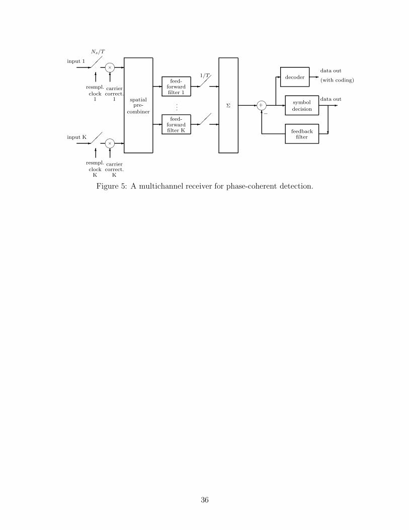
Multichannel signal processing for coherent detection
In many of the underwater acoustic channels multipath structure may exhibit one or more
components which carry the energy similar to that of the principal arrival. As the time
progresses, it is not unusual for these components to exceed in energy the principal arrival
(e.g., see Fig.2). The fact that the strongest multipath component may not be well defined
makes the extraction of carrier reference a difficult task in such a channel. To establish
coherent detection in the presence of strong multipath, a technique based on simultaneous
synchronization and multipath compensation may be used [19]. This technique is based on
joint estimation of the carrier phase and the parameters of a decision-feedback equalizer,
where the optimization criterion is minimization of the mean-squared error (MSE) in the
data estimation process. In addition, the equalizer/synchronizer structure can be extended
16
to include a number of input array channels [20, 40]. Spatial diversity combining has shown
superior performance in a number of channels, as well as potential for dealing with several
types of interference. In Fig.5, the multichannel equalizer is shown, preceded by an additional
pre-combiner, which may or may not be used depending on the application and the number
of available received channels.
The input signals to the baseband processor are the A/D converted array signals, brought
to baseband using nominal carrier and lowpass filtering. The signals are frame-synchronized
using a known channel probe (usually a short Barker sequence transmitted in phase and
quadrature at the data rate). Baseband processing begins with downsampling, which may
be carried out to as few as 2 samples per symbol interval (Ns = 2), since the signals are shaped
at the transmitter to have a raised-cosine spectrum which limits their maximal frequency to
less than 1/T . Since there is no feedback to the analog part of the receiver, the method is
suitable for an all-digital implementation.
For applications where transmitter and receiver are not moving at a high speed, but only
drifting with water, no explicit adjustment of the sampling clock is needed. It will implicitly
be accomplished during the process of adaptive fractionally spaced equalization. The front
section of the equalizer will also perform adaptive matched filtering and linear equalization.
To correct for the carrier offset, the signals in all channels are phase-shifted by the amount
estimated in the process of joint equalization and synchronization. After coherent combin-
ing, the ISI resulting from the previously transmitted symbols (postcursors) is canceled in
the feedback section of the equalizer. This receiver structure is applicable to any linear mod-
ulation format, such as M-PSK, or M-QAM, the only difference being in the way in which
symbol decision is performed.
In addition to combining and equalization, signal processing at the receiver includes the
operation of decoding if the signal at the transmitter was encoded. For example, in a DSP
implementation of the receiver two coding methods are used: concatenated coding of an
outer Reed Solomon code and an inner cyclic block code (Hamming, BCH), and punctured
convolutional coding with interleaving. Alternatively, trellis coded modulation, compatible
with PSK and QAM signals, provides an effective means of improving performance on a
17
band-limited channel.
The receiver parameters that are adaptively adjusted are the weights of the pre-combiner,
the tap-weights of the feedforward filters, the carrier phase estimates, and the tap-weights
of the feedback filter. A single estimation error is used for the adaptation of all parameters.
This error is the difference between the estimated data symbol at the input to the decision
device, and its true value. During the initial training mode, the true data symbols are
known. After the training period, when the receiver parameters have converged, the on-
line symbol decisions are fed back to the equalizer and used to compute the error. The
adaptive algorithm used to update the receiver parameters is a combination of the second-
order digital phase-locked loop (PLL) for the carrier phase estimates, and the RLS algorithm
for the multichannel equalizer tap weights. The complexity of the multichannel equalizer
grows with the number of receiver array sensors. For this reason, the spatial pre-combiner
may be used to limit the number of equalizer channels, but still make use of the diversity gain.
The pre-combiner weights can be estimated jointly with the rest of adjustable parameters.
The details of the joint adaptation are given in [40].
The receiver is adaptively adjusted to coherently combine the multiple signal arrivals, and
thus exploit both spatial and temporal, or multipath diversity gain. In this manner, it
differs from a receiver based on adaptive beamforming which is adjusted to null out the
signal replicas arriving from angles different than that of the desired path. The signal
isolated by a beamformer usually has to be processed by a separately optimized equalizer
to compensate for the residual ISI which arises because the beamformer cannot completely
eliminate the multipath interference. Since it is not constrained by angular resolution, the
method of multichannel equalization may be used with as few as two input channels, and
is applicable to a variety of underwater acoustic channels, regardless of the range-to-depth
ratio. In applications where large arrays are available, the pre-combiner reduces receiver
complexity, while preserving the multichannel diversity gain.
The method of adaptive multichannel combining and equalization was demonstrated to be
effective in underwater channels with fundamentally different mechanisms of multipath for-
mation. Experimental results include data rates of 2 kbps over three convergence zones
18
(200 km or 110 nautical miles) in deep water; 2 kbps over 90 km (50 nautical miles) in
shallow water, and up to 40 kbps over 1-2 km in rapidly varying shallow water channels.
This method is enhanced by the use of a pre-combiner [40] which reduces a large number
of input channels to a smaller number for subsequent multichannel equalization. By careful
design, full diversity gain can be preserved by this technique. More than one channel at the
output of the combiner is usually required, but this number is often small (e.g., three). The
fact that diversity gain may be preserved is explained by multipath correlation across the
receiver array. In addition to the reduced computational complexity, smaller adaptive filters
result in less noise enhancement, contributing to improved performance.
Interference cancellation and multi-user detection
Sources of interference in underwater acoustic channels include external interference and
internal interference, generated within the system. External sources of interference include
noise coming from on-board machinery or other nearby acoustic sources, as well as the
propulsion and flow noise associated with the underwater vehicle launch process. Internal
noise, which has signal-like characteristics, arises in the form of echo in full-duplex systems,
and in the form of multiple-access interference generated by other users operating within the
same network.
Methods for cancellation of interference in the form band-limited white noise and multiple
sinusoidal interference were investigated in [41]. It was found that the multichannel receiver
structure of Fig.5 was effective in canceling the interference while simultaneously detecting
the desired signal. Noise cancellation is performed simply by providing a reference of the
noise signal to one of the multichannel combiner inputs, while cancelation of the sinusoidal
interferer may be performed even without the reference signal. By virtue of having the
training sequence, the multichannel combiner has the capability to adaptively filter the
interfering signal out, and extract the desired signal.
A multiple-access communication system represents a special case of structured interference
environment, such as that arising in a code-division multiple access system based on di-
rect sequence spread spectrum modulation. Similarly as before, the adaptive multichannel
19
receiver of Fig.5 was experimentally shown to have excellent capabilities in the role of a
multiuser detector [42]. For systems with high spreading gain, such as those used to provide
additional low probability of detection (LPD) needed for operation in hostile environments,
signal processing is performed at the chip rate (as opposed to symbol-rate) to accommodate
the time-variation of the channel that can be significant during one symbol interval, thus
taking advantage of the available processing gain [43].
Time-reversal
A different approach to learning the channel has been pursued through a technique called
time-reversal or phase conjugation [44]. This technique uses a time-reversed replica of a
received signal waveform to implement a filter matched to that waveform, and can operate
either passively or actively. Passive time-reversal resides at the receiver side only, where its
role is to acquire a probe signal and use it to perform low-complexity front-end matched
filtering prior to multichannel equalization or interference cancellation [45, 46]. In contrast,
active time-reversal operates at the transmitter side, where its role is to time-reverse the
feedback signal and use it as the basic pulse (basic transmit waveform) that will best match
the channel. By doing so, the transmitter, typically equipped with a large array, focuses
its energy not only in time, but also in space (see [44] and references therein). In repeated
actions of this type, both ends of the link can focus their energy. Passive time-reversal has
also been used for multi-user detection [46].
Coding, turbo equalization and advanced channel estimation
With the feasibility of high rate communications established, research has been extremely
active on a number of interesting topics [47]. Single-carrier modulation/detection is being
improved using powerful coding and turbo equalization methods, [48], [49], while multi-
carrier modulation/detection methods, which we discuss in the next section, have emerged
as a viable alternative to single-carrier broadband modulation. Both types of systems have
been extended to multi-input multi-output configurations that provide spatial multiplexing
(the ability to send parallel data streams from multiple transmitters), and bit rates of several
tens of kbps have been demonstrated experimentally.
20
Adaptive channel estimation has received special attention as it holds the key to improved
equalization. The acoustic channel is often sparse, i.e. there are only several significant
paths that populate the total and possibly long delay spread. This fact has an important
implication on channel estimation and the associated equalization methods. Namely, if
the entire multipath spread is represented by L samples taken at intervals 1/B, where B
is the system bandwidth, fewer than L coefficients may suffice to represent the channel
response. Ideally, only as many coefficients as there are propagation paths, P < L, are
needed. Channel modeling thus becomes an important aspect of signal processing, and
sparsing has been investigated for decision-feedback equalization [50, 51], turbo equalization
[48, 49], and multi-carrier detection [52, 53, 56]. It is also important to note that although
a greater bandwidth implies more samples needed to represent the channel, it also implies
a better resolution in delay (less smearing in the observable channel response). Hence,
although the attendant signal distortion is perceived as more severe, channel estimation will
be more efficient if a proper sparse model is used, which may in turn lead to improved signal
processing. In addition, signaling at a higher rate enables more frequent channel observations
and, consequently, easier channel tracking [26].
Multi-carrier systems
Multi-carrier modulation is a technique used to combat the frequency-selectivity of the chan-
nel. This technique, in the form of orthogonal frequency division multiplexing (OFDM), has
been adopted for many of the wireless radio systems, including wireless local area networks
(WLAN), digital audio and video broadcast (DAB/DVB), and the next generation of cel-
lular systems. Over the past several years, it has also come into the forefront of acoustic
communications research, and several efforts at implementing an OFDM acoustic modem
have emerged as well.
The appeal of OFDM lies in the computational efficiency of FFT-based processing, and in
the fact that it easily scales to different bandwidths. Unlike with single-carrier systems,
where the equalizer length has to be adjusted in accordance with the bandwidth B because
it determines the symbol duration and hence the extent of ISI, with OFDM it simply suffices
21
to increase/decrease the number of carriers K, i.e. the size of the FFT, while keeping the
same carrier separation ∆f = B/K.
In addition, by virtue of having a narrowband signal on each carrier, OFDM is easily con-
ducive to MIMO processing [52, 55, 56], adaptive modulation [57], differentially coherent
detection [58], and partial-band interference suppression [59]. However, its sensitivity to fre-
quency offset and time-variation of the channel demands special attention. Issues related to
power efficiency also need to be kept in mind, as OFDM is sensitive to non-linear distortions
[60].
OFDM signal processing encompasses two stages: pre-FFT synchronization and post-FFT
data detection. To account for motion-induced Doppler frequency shifting, which can amount
to more than a full carrier spacing, front-end resampling is often necessary. A simple method
for estimating the needed resampling rate is to measure the time between two synchronization
preambles that frame several OFDM blocks and compare it to the expected frame duration
[54]. Since the Doppler factor is relatively large to begin with (e.g., on the order of 10−3 for
a relative velocity of 1.5 m/s) Doppler shifting that remains after initial resampling cannot
be neglected.
Channel estimation for OFDM systems has been addressed in different forms: in one, each
OFDM block is processed independently of the other blocks, thus allowing for the possibil-
ity that the channel changes completely from one block to another [53, 55], while another
form exploits correlation between adjacent blocks [52, 56], which makes it advantageous on
slowly varying channels. Similarly as in single-carrier systems, accurate channel estima-
tion is the key to successful data detection in OFDM, and it benefits greatly from proper
channel modeling to reduce the number of unknown parameters that need to be estimated.
Methods for identification of sparse systems, such as matching pursuit and basis pursuit,
which improve upon traditional least squares estimation, were found to be beneficial and
well-suited to channel estimation in acoustic OFDM. These methods have been applied to
both block-individual channel estimation that uses pilot carriers only, and to block-adaptive,
decision-directed channel estimation [61].
Time-variability of the channel can have an adverse effect on an OFDM system. If the symbol
22
rate (number of carriers) is increased in a given bandwidth beyond the point at which the
channel remains approximatley constant during one OFDM block, inter-carrier interference
(ICI) will arise. ICI equalization then becomes necessary. The problem is analogous to that
of ISI equalization in single-carrier systems, except that the equalizer now operates across
carriers, and typically involves fewer interfering terms. However, unlike in single-carrier
systems, the problem is avoidable simply by limiting the number of carriers. Methods based
on one-shot linear equalization of a full block of carriers [53, 62], as well as recursive linear or
decision-feedback equalization [63], were investigated. Further improvements are available
from front-end (pre-FFT) filtering, which extracts the information about the time-varying
channel before it has been lost in the process of FFT demodulation [64], [58].
The majority of acoustic OFDM systems addressed to-date have focused on coherent de-
tection and the attendant issues of channel estimation and Doppler tracking. However, a
properly designed OFDM system (one in which there is no ICI) is well suited to differen-
tially coherent detection as well. Differential encoding is preferably applied across carriers,
as frequency coherence is naturally satisfied with narrow carrier spacing which simultane-
ously supports bandwidth efficiency. Additional forward error correction coding can also be
applied, and was mostly used in the form of low-density parity check (LDPC) codes [65].
Experimental results [58] have demonstrated the benefits of differentially coherent OFDM,
whose computational complexity much lower than that of any coherent system, and whose
performance can surpass that of coherent detection when channel estimation fails.
Adaptive modulation
Adapting the transmitter to the channel characteristics has been considered in different
forms, including active time-reversal [44] and single-mode excitation [67]. Adaptive modu-
lation has been considered in the context of single-carrier MIMO systems [66], and, more
recently, in the context of multi-carrier systems [57], where adaptive power and/or rate con-
trol (adaptive bit loading) can be implemented easily by adjusting the amplitude and/or the
modulation level of each carrier separately. The performance improvement available from
these techniques is contingent on the quality of the channel state information that is fed
23
back to the transmitter. Recent results [57], which report on an experimental demonstration
of this type, suggest the possibility to isolate the more slowly varying channel parameters
(i.e. the predictable propagation path gains) from the more rapidly varying ones (phases)
and use them to design an adaptive modulation system.
Future work
Existing results serve as the encouragement for future developments that will include not
only point-to-point links, but multi-agent underwater networks, as well as fundamental ques-
tions of system capacity. In addition to bandwidth-efficient modulation/coding and signal
processing techniques, future systems will rely on dedicated data compression algorithms, ac-
curate statistical channel models, feedback-based techniques for optimal resource allocation,
and system-level integration of communications, control, sensing and navigation functions.
24
References
[1] L.Brekhovskikh and Y.Lysanov, Fundamentals of Ocean Acoustics, New York:
Springer, 1982.
[2] S.Flatte (ed.), Sound Transmission Through a Fluctuating Ocean, Cambridge, UK:
Cambridge University Press, 1979.
[3] M.Stojanovic and J.Preisig, Underwater acoustic communication channels: Prop-
agation models and statistical characterization, IEEE Communications Magazine,
vol.47: 84-89, Jan. 2009.
[4] R.Coates, Underwater Acoustic Systems, New York: Wiley, 1989.
[5] X.Che, I.Wells, G.Dickers, P.Kear and X.Gong, Re-evaluation of RF electro-
magnetic communication in underwater sensor networks, IEEE Communications
Magazine, 48: 143 -151, Dec. 2010.
[6] N.Farr, A.Bowen, J.Ware, C.Pontbriand and M.Tivey, An integrated, underwater
optical /acoustic communications system, Proc. Oceans’10, May 2010.
[7] L.Freitag,M.Grund, S.Singh, J.Partan, P.Koski and K.Ball, The WHOI micro-
modem: an acoustic communications and navigation system for multiple platforms,
Proc. Oceans’05, vol.2: 1443 -1448, 2005.
[8] L.Freitag and M.Stojanovic, Basin-scale acoustic communication: a feasibility study
using tomography m-sequences, Proc. Oceans’01, vol 4: 2256 -2261, 2001.
[9] L.Freitag, M.Johnson and D.Frye, High-rate acoustic communications for ocean
observatories-performance testing over a 3000 m vertical path, Proc. Oceans’00,
2000.
[10] A.Quazi and W.Konrad, Underwater acoustic communications, IEEE Comm. Mag-
azine: 24-29, 1982.
25
[11] J.Catipovic, Performance limitations in underwater acoustic telemetry, IEEE J.
Oceanic Eng., vol. 15: 205-216, 1990.
[12] A.Baggeroer, Acoustic telemetry - an overview, IEEE J. Oceanic Eng., vol. 9: 229-
235, 1984.
[13] M.Stojanovic Recent advances in high rate underwater acoustic communications,
IEEE J. Oceanic Eng., vol. 21: 125-136, 1996.
[14] D.Kilfoyle and A.Baggeroer, The state of the art in underwater acoustic telemetry,
IEEE J. Oceanic Eng., vol. 25: 4-27, 2000.
[15] J.Heideman, M.Stojanovic and M.Zorzi, Underwater sensor networks: Applications,
advances, and challenges, Philosophical Transactions of the Royal Society (A), 158-
175, Jan. 2012.
[16] A.Kaya and S.Yauchi, An acoustic communication system for subsea robot, Proc.
Oceans’89: 765-770, 1989.
[17] M.Suzuki and T.Sasaki, Digital acoustic image transmission system for deep sea
research submersible, Proc. Oceans’92: 567-570, 1992.
[18] S.Singh, S.Webster, L.Freitag, L.Whitcomb, K.Ball, J.Bailey and C.Taylor, Acoustic
communication performance of the WHOI Micro-modem in sea trials of the Nereus
vehicle to 11,000 m depth, Proc. Oceans’09, Oct.2009.
[19] M.Stojanovic, J.A.Catipovic and J.G.Proakis, Phase coherent digital communica-
tions for underwater acoustic channels, IEEE J. Oceanic Eng., vol. 19: 100-111,
1994.
[20] M.Stojanovic, J.A.Catipovic and J.G.Proakis, Adaptive multichannel combining and
equalization for underwater acoustic communications, Journal of the Acoustical So-
ciety of America, vol. 94 (3), Pt. 1: 1621-1631, 1993.
[21] B.Woodward and H.Sari, Digital underwater voice communications, IEEE J. Oceanic
Eng., vol. 21: 181-192, Apr. 1996.
26
[22] D.Hoag, V.Ingle and R.Gaudette, Low-bit-rate coding of underwater video using
wavelet-based compression algorithms, IEEE J. Oceanic Eng. vol. 22: 393-400, 1997.
[23] J.Ribas, D.Sura and M.Stojanovic, Underwater wireless video transmission for su-
pervisory control and inspection using acoustic OFDM, proc. Oceans’10, Sept. 2010.
[24] M.Chitre, J.Potter and S.-H.Ong, Optimal and near-optimal signal detection in snap-
ping shrimp dominated ambient noise, IEEE J. Oceanic Eng. vol. 31: 498-503, Apr.
2006.
[25] G.S.Howe et al., Sub-sea remote communications utilising an adaptive receiving
beamformer for multipath suppression, Proc. Oceans’94: 313-316 (I), 1994.
[26] M.Stojanovic, J.G.Proakis and J.A. Catipovic, Performance of a high rate adaptive
equalizer on a shallow water acoustic channel, J. Acoust. Soc. Amer., vol. 100 (4),
Pt. 1, pp. 2213-2219, 1996.
[27] A.Falahati, B.Woodward and S.Bateman, Underwater acoustic channel models for
4800 b/s QPSK signals, IEEE J. Oceanic Eng., vol.16: 12-20, 1991.
[28] C.Bjerrum-Niese, L.Bjorno, M.Pinto and B.Quellec, A simulation tool for high data-
rate acoustic communication in a shallow-water, time-varying channel, IEEE J.
Oceanic Eng., vol. 21: 143-149, 1996.
[29] P.Qarabaqi and M.Stojanovic, Statistical characterization and computationally effi-
cient modeling of a class of underwater acoustic communication channels, IEEE J.
Oceanic Eng., vol.38: 701-717, Oct. 2013.
[30] W.B.Yang and T.C.Yang, High-frequency channel characterization for M-ary
frequency-shift-keying underwater acoustic communications, J. Acoust. Soc. Amer.,
vol. 120 (5): 2615-2626, Nov. 2006.
[31] B.Tomasi, G.Zappa, K.McCoy, P.Casari and M.Zorzi, Experimental study of the
space-time properties of acoustic channels for underwater communications, Proc.
Oceans’10, May 2010.
27
[32] F. Socheleau, C.Laot and J.Passerieux, Stochastic replay of non-WSSUS underwater
acoustic communication channels recorded at sea, IEEE Trans. Sig. Proc., vol. 59:
4838 -4849, Oct. 2011.
[33] M.Chitre, A high-frequency warm shallow water acoustic communications channel
model and measurements, J. Acoust. Soc. Amer., vol. 122 (5): 2580-2586, Nov. 2007.
[34] J.Zhang, J.Cross and R.Zheng, Statistical channel modeling of wireless shallow wa-
ter acoustic communications from experiment data, Proc. Military Communicatoins
Conf., 2412 -2416, Nov. 2010.
[35] J.Catipovic, A.Baggeroer, K.Von der Heydt and D.Koelsch, Design and performance
analysis of a digital acoustic telemetry system for the short range underwater chan-
nel, IEEE J. Oceanic Eng., vol. 9: 242-252, Oct. 1984.
[36] D.Green and J.Rice, Channel-tolerant FH-MFSK acoustic signaling for undersea
communications and networks, IEEE J. Oceanic Eng., vol. 25: 28-39, Jan. 2000.
[37] J.Catipovic, M.Deffenbaugh, L.Freitag and D.Frye, An acoustic telemetry system for
deep ocean mooring data acquisition and control, Proc. Oceans’89: 887-892, 1989.
[38] K.Scussel, J.Rice and S.Merriam, A new MFSK acoustic modem for operation in
adverse undewater channels, Proc. Oceans’97, 1997.
[39] R.F.W.Coates, M.Zheng and L.Wang, BASS 300 PARACOM: A model underwater
parametric communication system, IEEE J. Oceanic Eng., vol. 21: 225-232, 1996.
[40] M.Stojanovic, J.A.Catipovic and J.G.Proakis, Reduced-complexity multichannel
processing of underwater acoustic communication signals, Journal of the Acousti-
cal Society of America, vol. 98 (2), Pt. 1: 961-972, 1995.
[41] J.Catipovic, M.Johnson and D.Adams, Noise canceling performance of an adaptive
receiver for underwater communications, Proc. 1994 Symposium on AUV Technology:
171-178, 1994.
28
[42] M.Stojanovic and Z.Zvonar, Multichannel processing of broadband multiuser com-
munication signals in shallow water acoustic channels, IEEE J. Oceanic Eng., vol.
21: 156-166, 1996.
[43] M.Stojanovic and L.Freitag, Multichannel detection for wideband underwater acous-
tic CDMA communications, IEEE J. Oceanic Eng., vol. 31: 685-695, July 2006.
[44] G.Edelmann, H.C.Song, S.Kim, W.Hodgkiss, W.Kuperman, and T. Akal, Underwa-
ter acoustic communications using time reversal, IEEE J. Oceanic Eng., vol. 30: 852
-864, Oct. 2005.
[45] J.Flynn, J.Ritcey, D.Rouseff, and W.L.J.Fox, Multichannel equalization by decision-
directed passive phase conjugation: experimental results, IEEE J. Oceanic Eng., vol.
29: 824 - 836, July 2004.
[46] S.E.Cho, H.C.Song and W.Hodgkiss, Successive interference cancellation for under-
water acoustic communications, IEEE J. Oceanic Eng., vol. 46: 490 -501, Oct. 2011.
[47] A.Singer, J.Nelson and S.Kozat, Signal processing for underwater acoustic commu-
nications, IEEE Communications Magazine, vol.47: 90-96, Jan. 2009.
[48] S.Roy, T.Duman and V.McDonald, Error rate improvement in underwater MIMO
communications using sparse partial response equalization, IEEE J. Oceanic Eng.,
vol. 34: 181 -201, April 2009.
[49] J.-W.Choi, T.Riedl, K.Kyeongyeon, A.Singer and J.Preisig, Adaptive linear turbo
equalization over doubly selective channels, IEEE J. Oceanic Eng., vol. 36: 473 -489,
Oct. 2011.
[50] M.Stojanovic, Channel-estimation-based adaptive equalization of underwater acous-
tic signals, Elsevier Journal on Physical Communication, 146-161, June 2008.
[51] W.Li and J.Preisig, Estimation of rapidly time-varying sparse channels, IEEE J.
Oceanic Eng., vol. 32: 927 -939, Oct. 2007.
29
[52] M.Stojanovic, MIMO OFDM over underwater acoustic channels, Proc. 43-rd Asilo-
mar Conf. on Signals, Systems and Computers, 605 -609, Nov. 2009.
[53] C.Berger, S.Zhou, J.Preisig and P. Willett, Sparse channel estimation for multicarrier
underwater acoustic communication: From subspace methods to compressed sensing,
IEEE Trans. Signal Process., vol.58: 17081721, MArch 2010.
[54] B.Li, S.Zhou, M.Stojanovic, L.Freitag and P.Willett, Multicarrier communication
over underwater acoustic channels with nonuniform Doppler shifts, IEEE J. Oceanic
Eng., vol. 33: 198-209, April 2008.
[55] B.Li, J.Huang, S.Zhou, K.Ball, M.Stojanovic, L.Freitag and P.Willett, MIMO-
OFDM for high-rate underwater acoustic communications, IEEE J. Oceanic Eng.,
vol. 34: 634 -644, Oct 2009.
[56] E.Zorita and M.Stojanovic, Space−frequency block coding for underwater acoustic
communications, IEEE J. Oceanic Eng., vol. 40: 303-314, April 2015.
[57] A.Radosevic, R.Ahmed, T. Duman, J.Proakis, and M.Stojanovic, Adaptive OFDM
modulation for underwater acoustic communications: Design considerations and ex-
perimental results, IEEE J. Oceanic Eng., vol.39: 357-370, April 2014. ,
[58] Y.Aval and M.Stojanovic, Differentially coherent multichannel detection of acoustic
OFDM signals, IEEE J. Oceanic Eng., vol.40: 251-268, April 2015.
[59] Z.-H. Wang, S. Zhou, J. Catipovic and P. Willett, Parameterized cancellation
of partial-band partial-block-duration interference for underwater acoustic OFDM,
IEEE Trans. Sig. Proc., vol. 60: 1782-1795, April 2012.
[60] G.Rojo and M.Stojanovic, Peak-to-average power ratio (PAR) reduction for acoustic
OFDM systems, Marine Technology Society (MTS) Journal, 30-41, July 2010.
[61] A. Radosevic, T.Duman, M. Stojanovic and J.Proakis, Selective decision directed
channel estimation for UWA OFDM systems, Proc. 49th Annual Allerton Conference
on Communication, Control, and Computing, 647 -653, Sept. 2011.
30
[62] J.Huang, S.Zhou, J.Huang, C.Berger and P.Willet, Progressive inter-carrier inter-
ference equalization for OFDM transmission over time-varying underwater acoustic
channels, IEEE J. Select. Topics Sig. Proc., vol. 5: 1524 -1536, Dec. 2011.
[63] K.Tu, D.Fertonani, T.Duman, M.Stojanovic, J.Proakis and P.Hursky, P.Mitigation
of intercarrier interference for OFDM over time-varying underwater acoustic chan-
nels, IEEE J. Oceanic Eng., vol. 36: 156 -171, April 2011.
[64] S.Yerramalli, M.Stojanovic and U.Mitra, Partial FFT demodulation: A detection
method for Doppler distorted OFDM systems, IEEE Trans. Sig. Proc., vol. 60:
5906-5918, Nov. 2012.
[65] J. Huang, S. Zhou, and P. Willett, Nonbinary LDPC coding for multicarrier under-
water acoustic communication,” IEEE J. Select. Areas Commun., vol. 26: 1684-1696,
Dec. 2008.
[66] D.Kilfoyle, J.Preisig and A.Baggeroer, Spatial modulation experiments in the un-
derwater acoustic channel, IEEE J. Oceanic Eng., vol. 30: 406 - 415, April 2005.
[67] J.Buck, J.Preisig, M.Johnson and J.Catipovic, Single-mode excitation in the shallow-
water acoustic channel using feedback, IEEE J. Oceanic Eng., vol. 22: 281 -291, April
1997.
31
0 2 4 6 8 10 12 14 16 18 200
10
20
30
40
50
60
70
5km
10km
50km
100km
frequency [kHz]
rela
tive
SN
R [d
B]
Figure 1: Frequency-dependent portion of SNR.
32
0
5
10
15
-40
-20
0
20
40
0
0.2
0.4
0.6
0.8
time [s]delay [ms]
tx depth : 100 m, rx depth : 640 m
Channel # 6 : omnidirectional
Rate : 333 sps
Range : 110 nautical miles
Figure 2: Ensemble of long-range channel responses in deep water (approx 2000 m) off the
coast of California, during the month of January. Carrier frequency is 1 kHz. Rate at which
quaternary data symbols used for channel estimation were transmitted is given in symbols
per second (sps).
33
0
5
10
15-50
0
50
0
0.2
0.4
0.6
0.8
time [s]delay [ms]
tx depth : 25 m, rx depth : 23 m
Channel # 8 : omnidirectional
Rate : 333 sps
Range : 48 nautical miles
Figure 3: Ensemble of long-range channel responses in shallow water (approx 50 m) off the
coast of New England, during the month of May. Carrier frequency is 1 kHz.
34
time [s]delay [ms]
tx depth : 8 m, rx depth : 3.5 m
Channel # 1 : directional
Rate : 500 sps
Range : 2 nautical miles
02
46
810
-10
-5
0
5
100
0.2
0.4
0.6
0.8
1
1.2
1.4
1.6
Figure 4: Ensemble of medium-range channel responses in shallow water (approx 20 m) near
the coast of New England, during the month of February. Carrier frequency is 15 kHz.
35
input K-�
�
6resmpl.
clockK
m×6
-
carriercorrect.
K
input 1-�
�Ns/T
6resmpl.
clock1
m×6
-
carriercorrect.
1 spatialpre-
combiner
-
-
feed-forwardfilter K
feed-forwardfilter 1
-
-
��
��
1/T
-
-
.
..Σ - m+ - symbol
decision-
data out
?feedbackfilter
6−
- decoderdata out
(with coding)-
Figure 5: A multichannel receiver for phase-coherent detection.
36
List of Figures
1 Frequency-dependent portion of SNR. . . . . . . . . . . . . . . . . . . . . . . 32
2 Ensemble of long-range channel responses in deep water (approx 2000 m) off
the coast of California, during the month of January. Carrier frequency is
1 kHz. Rate at which quaternary data symbols used for channel estimation
were transmitted is given in symbols per second (sps). . . . . . . . . . . . . 33
3 Ensemble of long-range channel responses in shallow water (approx 50 m) off
the coast of New England, during the month of May. Carrier frequency is 1
kHz. . . . . . . . . . . . . . . . . . . . . . . . . . . . . . . . . . . . . . . . . 34
4 Ensemble of medium-range channel responses in shallow water (approx 20
m) near the coast of New England, during the month of February. Carrier
frequency is 15 kHz. . . . . . . . . . . . . . . . . . . . . . . . . . . . . . . . 35
5 A multichannel receiver for phase-coherent detection. . . . . . . . . . . . . . 36
37