Embed Size (px)
Citation preview
7/17/2004 1
Understanding Vibration Systems
BySteven Wood

7/17/2004 2
Shaker SystemElectro-Dynamic ExciterPower Amplifier
Cooling Blower
Vibration Controller
Accelerometer
7/17/2004 3
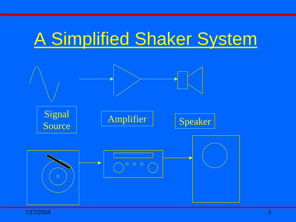
Signal Source
Amplifier Speaker
A Simplified Shaker System

7/17/2004 4
Shaker ComponentsUpper and lower field coils (electromagnet) create DC magnet flux in the gap between the compensation bands and the armature assembly
Armature assemblies may be inductiveinductive or conductive.conductive.
7/17/2004 5
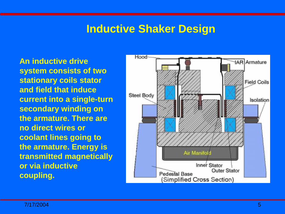
An inductive drive system consists of two stationary coils stator and field that induce current into a single-turn secondary winding on the armature. There are no direct wires or coolant lines going to the armature. Energy is transmitted magnetically or via inductive coupling.
Inductive Shaker Design
7/17/2004 6
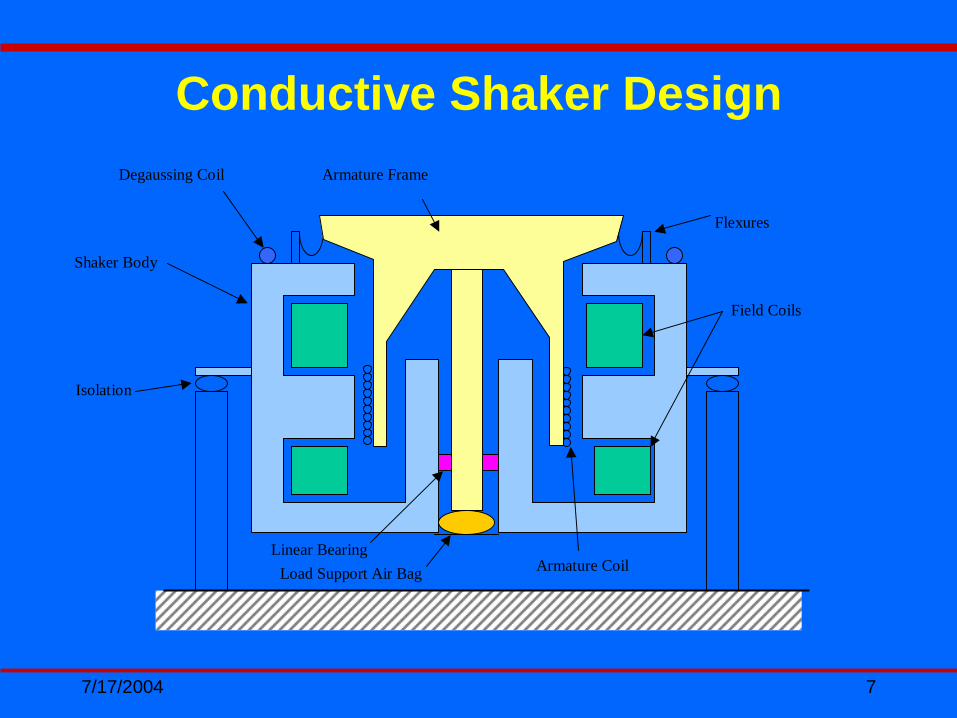
A conductive armature, as you will see on the following slide, receives its power directly from the power amplifier “direct coupled.”
Shaker Components Continued…
7/17/2004 7
Load Support Air Bag
Field Coils
Armature Frame
Shaker Body
Armature Coil
Degaussing Coil
Linear Bearing
Flexures
Isolation
Conductive Shaker Design
7/17/2004 8
• Air Plenum ( Directs the air exiting the shaker body and entering the blowers input flange)
• Current Lead (Provides electrical path between the Amplifier and the Shaker armature)
• Air Isolation Spring Regulator (Regulates air pressure to air isolation springs)
• Load Support Air Regulator (Regulates air pressure to rolling diaphragm load support)
• Compensating Rings (Converts the armature coil or “Solenoid” into a true electrical transformer) (Creates a lower impendence in the primary thereby reducing Amplifier output requirements that change with frequency)
Shaker ComponentsContinued…

7/17/2004 9
• Lower guidance bearing: (cross axial restraint of the armature assembly)
• Degaussing coils (cancels out/decreases the gauss level created by the field coils)
• Flexures(provide rotational restraint of armature typically below 200 Hz) Rolling Diaphragm (Load Support)
• Air Isolation Springs (Isolates the Shaker bodies vibration from the surrounding flooring at approximately 2 to 3 Hz)
Shaker ComponentsContinued…

7/17/2004 10
7/17/2004 11
7/17/2004 12
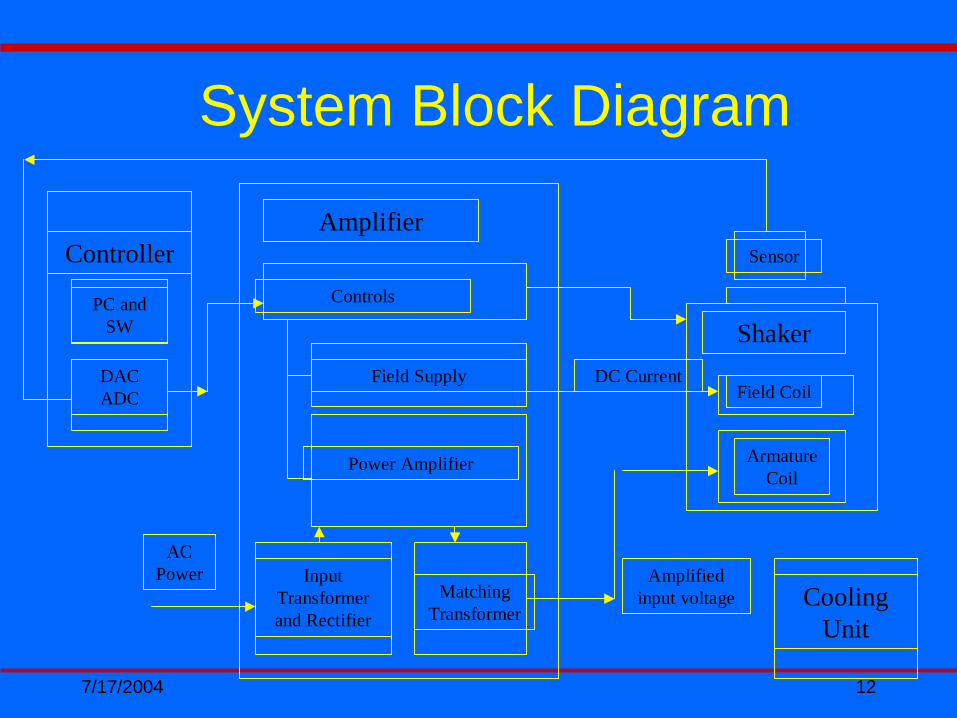
System Block Diagram
Amplifier
Controls
Field Supply
Power Amplifier
Input Transformer and Rectifier
Matching Transformer
AC Power
Controller
DAC ADC
PC and SW
Field Coil
Sensor
Shaker
Armature Coil
DC Current
Amplified input voltage Cooling
Unit

7/17/2004 13
Electrodynamic Exciter
• Maximum Force?• Maximum Displacement?• Maximum Velocity?• Maximum Acceleration?• Rotational and Cross-
Axial Performance?• Uniformity of Motion?• Armature Interface Size?

7/17/2004 14
Force Rating:
•Sine (5-2500Hz)--------------------- 6600 lbf
•Random (20-2000Hz)-------------- 6600 lbf
•Frequency Range------------------- 5-3,000Hz
Maximum displacement (Peak-Peak):
•Continuous duty -------------------- 38.1mm(1.5 in.)
•Shock --------------------------------- 50.8mm(2 in.)
•Between mechanical stops------ 55.9mm(2.2 in.)
Maximum Velocity------------------------ 1.8m/s (70.86 in/s)
Maximum Acceleration----------------- 100 gpk
Fundamental Resonance Frequency (Bare Table): 2300Hz±5%
Body Suspension Natural Frequency-Thrust Axis: 2.5 Hz
DS6600 Shaker System Specifications

7/17/2004 15
DS-6600VH/12-30 SHAKER
1
10
100
1 10 100 1000 10000
FREQUENCY-HZ
ACCE
LERA
TION
GPK
Bare Head
50 lb Payload
300 lb Payload
6,600 lbfSine/RandomArmature Mass 66.0lbs

7/17/2004 16
Bare Table Frequency ResponseArmature Resonance: 2290.7 Hz

7/17/2004 17
TEST: Bare Table Full Force Sine
•Force Achieved: 6600 lbf.•Acceleration: 100 G-pk•Armature Effective Mass: 66 lbs.•Test Duration: 7 Hrs.
7/17/2004 18
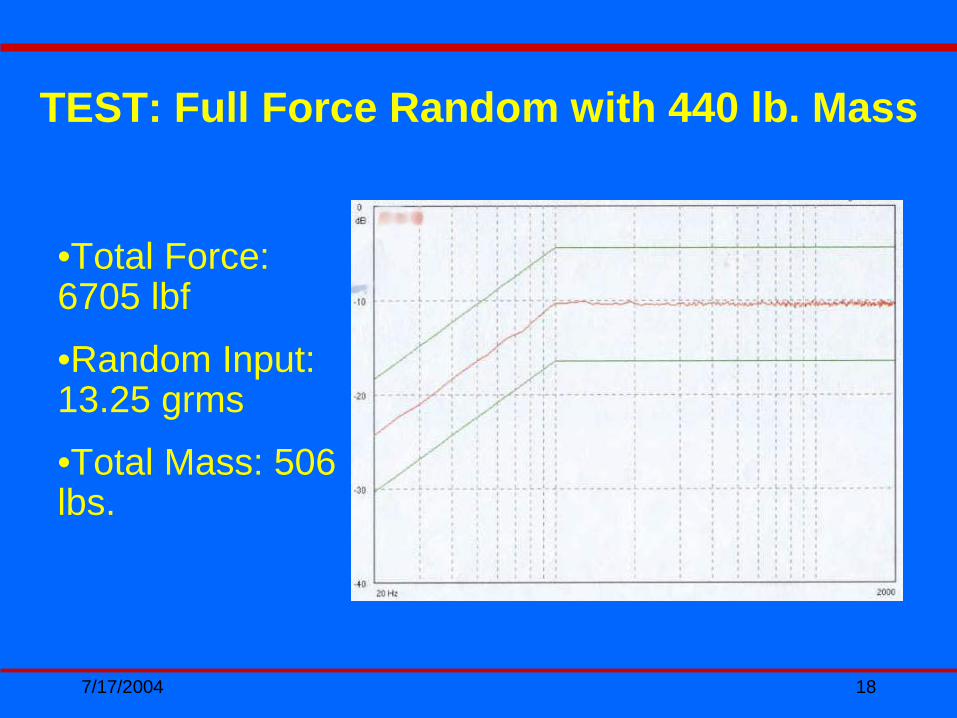
TEST: Full Force Random with 440 lb. Mass
•Total Force: 6705 lbf•Random Input: 13.25 grms•Total Mass: 506 lbs.

7/17/2004 19

7/17/2004 20
7/17/2004 21

7/17/2004 22
Dynamic Solutions Shaker Line

7/17/2004 23
DS SHAKER SYSTEMS
1
10
100
1000
1 10 100 1000 10000Payload Mass lbs.
Acc
eler
atio
n g'
s P
eak
DS-1300DS-2200DS-3300DS-4400DS-6600-12DS-9000DS-12000DS-13000

7/17/2004 24
Amplifier Considerations
• KVA Output?• Voltage &
Current Requirements of Exciter Armature?
• Voltage & Current
•Direct or Transformer Coupled?
Requirements of DC Field Supply?• IGBT versus MOSFET?• Interlocks?
7/17/2004 25
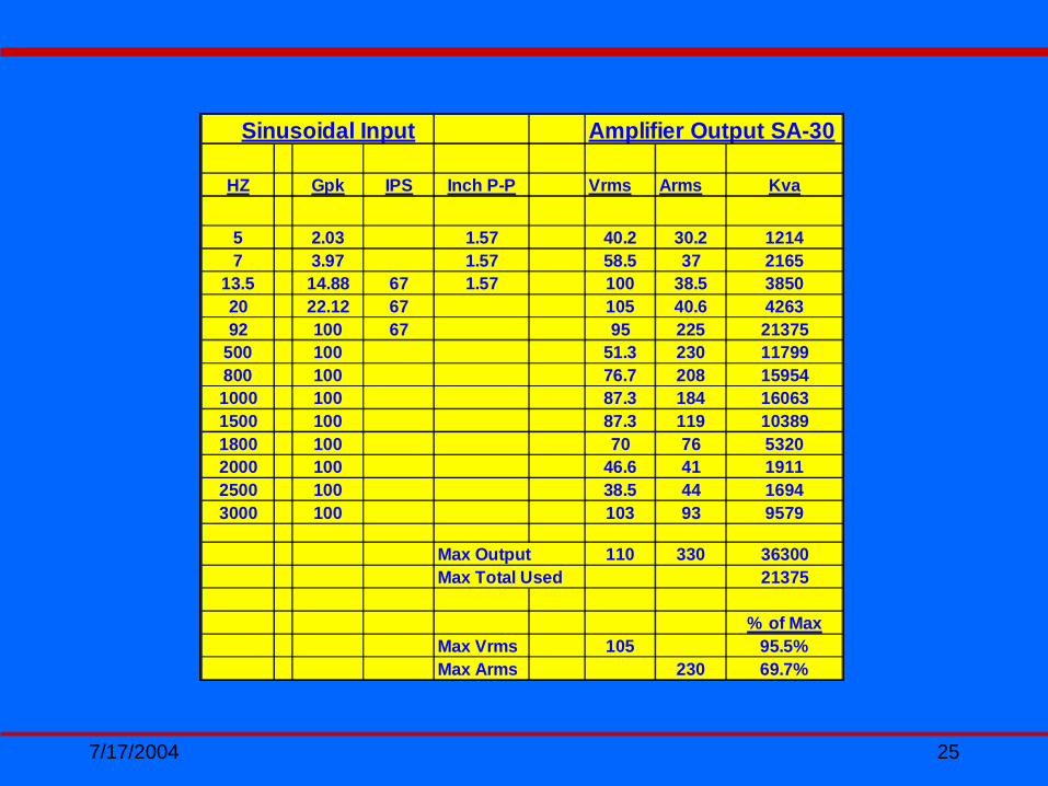
Sinusoidal Input Amplifier Output SA-30
HZ Gpk IPS Inch P-P Vrms Arms Kva
5 2.03 1.57 40.2 30.2 12147 3.97 1.57 58.5 37 2165
13.5 14.88 67 1.57 100 38.5 385020 22.12 67 105 40.6 426392 100 67 95 225 21375
500 100 51.3 230 11799800 100 76.7 208 159541000 100 87.3 184 160631500 100 87.3 119 103891800 100 70 76 53202000 100 46.6 41 19112500 100 38.5 44 16943000 100 103 93 9579
Max Output 110 330 36300Max Total Used 21375
% of MaxMax Vrms 105 95.5%Max Arms 230 69.7%
7/17/2004 26
Class “D” Solid State PWM Amplifiers
• Power Module: (The power module is basically a full bridge configuration consisting of switches and L-C filters. A rail voltage of 220 volts dc + or – 110 volts is brought to each half of the bridge and switched at 120 KHz. With no input voltage from the vibration controller, it has a 50% duty cycle, in phase; thus, no output voltage will appear at the output terminals. If a sine-wave, random or transient signal is present, each half of the bridge will be modulated so that the duty cycle will vary as the input signals rate. Each side is driven out of phase so that an amplified signal will appear across the output terminals. Voltage gain is the effective rail voltage times the percentage of modulation)
• Control Module: (The control module provides pre-amplification of the input signal, PWM clocking to the power module, external interlock control)

7/17/2004 27
7/17/2004 28
• Power supply: (provides power to the DC rail voltage supply, field supply and control power)
• Input power transformer: ( distributes power to various sectionsof the amplifier at different voltage levels relative to the impedance tapping of the secondary legs)
• Output transformer: (takes the amplifiers output and steps up ordown the voltage level in order to have a better impedance match between the amplifier and shaker)
7/17/2004 29
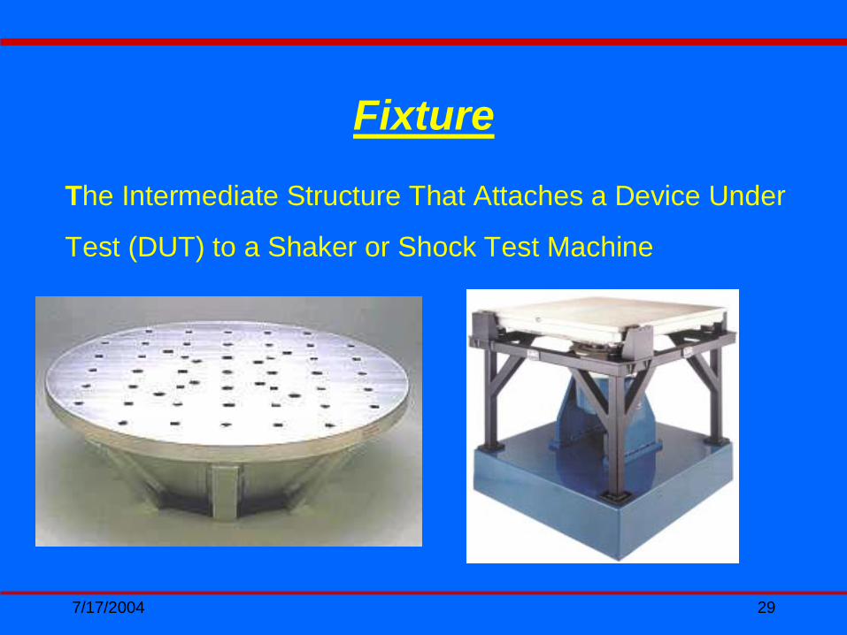
Fixture
The Intermediate Structure That Attaches a Device Under
Test (DUT) to a Shaker or Shock Test Machine
7/17/2004 30
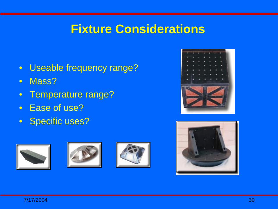
• Useable frequency range?• Mass?• Temperature range?• Ease of use?• Specific uses?
Fixture Considerations

7/17/2004 31
Purpose Of Fixture
• To uniformly transmit vibration to the mounting points of the Device Under Test (DUT) to levels and frequencies of the test specification
7/17/2004 32
Important Terms• Resonance: Resonance, a condition where the natural
frequency is equal to the forcing frequency
• Damping: Mitigates and reduces the effects of resonance's
• Transmissibility: The relationship between the input amplitude and the response amplitude. When the input and response amplitude are equal the Q is said to be 1 to 1
• Q: the ratio of input amplitude to response amplitude
• Decoupling: Occurs when the Input amplitude is greater in Q than the response amplitude. This typically occurs at frequencies greater than the natural frequency of the DUT.

7/17/2004 33
Fixture Design Tips
• Use materials that have high Damping indexes. The Q of the resonance is lowered, making the fixture easier to control and decoupling rates are greatly reduced
• Use light weight alloys to eliminate fixture mass
• Modulus to density ratios effect natural frequency

7/17/2004 34
Fixture Construction
• Bolting: Bolting is fast and simple way to construct a fixture. This method is not recommended for tests that exceed 250 HZ. Bolts will loosen up and decoupling will occur
• Machining: A fixture machined from solid stock is very good, there are no joints to work loose. This is desirable for small devices but to expensive and time consuming to build with larger devices
• Casting: Casting yields an excellent fixture. The monolithic construction eliminates many problems. Generally to expensive and time consuming
7/17/2004 35
• Welding: since fixtures are typically a one of a kind proposition, welding is the preferred method of fabrication
Note: plates to be welded should be thicker than specification. This will allow for machining that may be required if the material warped due to welding

7/17/2004 36
Material Choices
• Steel: seldom used for fixtures due to its mass and poor damping characteristics
• Aluminum: 6061T is widely used weighing about 2/3 less than steel but with a damping index of < .2 it is more desirable for low frequency testing or special applications were low damping is required, such as pyro-shock testing

7/17/2004 37
• Magnesium: AZ31B is the material of choice for most vibration tests due its mass 1/3 lighter than aluminum, damping index of 10.1 and is 70% more weldable than aluminum

7/17/2004 38
10.1124.065Magnesium
< .2106.098Aluminum
< .2106.283Steel
DampingIndex
SpecificStiffness
Weight per Cu.
Inch

7/17/2004 39
In conclusion the perfect fixture is:
• As light as possible• Very rigid• Highly damped• Has perfect transmissibility within the desired
frequency range (no resonance's or decoupling)• Welded or machined

7/17/2004 40
Accelerometers

7/17/2004 41
Accelerometer
A sensor or transducer or pickup for converting acceleration to an electrical signal. Two common types are piezoresistive and piezoelectric.
• Frequency response?• Calibration constant?• Temperature range?• Relative mass?

7/17/2004 42
• Piezoelectric (PE) transducer. One which depends upon deformation of its sensitive crystal or ceramic element to generate electrical charge and voltage. Many present-day accelerometers are PE.
• Piezoresistive (PR) transducer. One whose electrical output depends upon deformation of its semiconductor resistive element, offering greater resistance change than does the wire of a strain-gage transducer, for a given deformation.

7/17/2004 43
Signal conditioner: An amplifier following a sensor, which prepares the signal for succeeding amplifiers, transmitters, readout instruments, etc. May also supply sensor power
Charge amplifier: An amplifier which converts a charge input signal (as from an accelerometer) into an output voltage; A charge-to-voltage converter.
7/17/2004 44
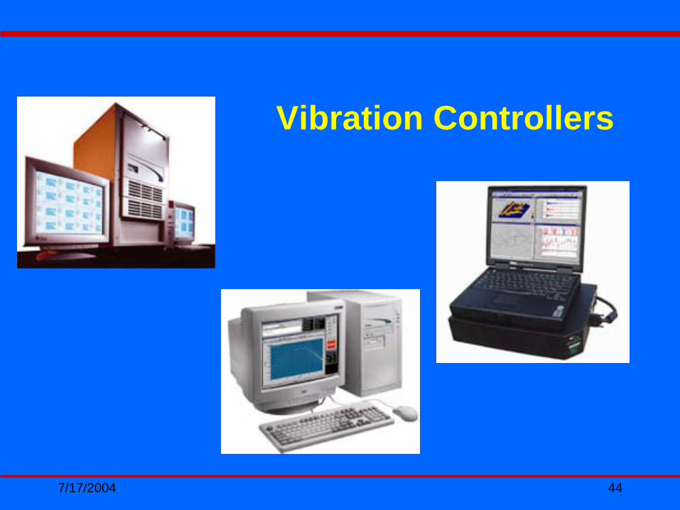
Vibration Controllers

7/17/2004 45
Control System (Brains)
• Iterative closed loop control pre-calculates drive signals but then modifies those signals based upon resulting motion, in order to better match measured with desired motions. Evaluation and modifications take place after each excitation, repeating until the desired result is achieved. Responses are measured and fed back to the control system so as to refine or modify drive signals in order to bring responses closer to the reference or desired motions

7/17/2004 46

7/17/2004 47
• ADC channels required?• Software required?• ADC sample rate?• Multiple DAC outputs?• Hardware quality? • Engineering features? (Transfer functions, phasing,
coherence, limiting, safety/abort, multiple graphics etc)
Considerations in selecting a Controller
7/17/2004 48
Input control signal. Originates in a control sensor; Sometimes selected between or averaged between several sensors. Used to regulate shaker intensity. (May originate in a force sensor for force-controlled testing.)
Response signal. The signal from a "response sensor”measuring the mechanical response of a mechanical system to an input vibration or shock.

7/17/2004 49
Open loop: control provides pre-computed or preconceived drive signals to the exciter system without modifying or refining those signals based on observation of the resulting motion.
Averaging: summing and suitably dividing several like measurements to improve accuracy or to lessen any asynchronous components.

7/17/2004 50
Hardware Overview
• A/D converter. (ADC) A device that changes an analog signal such as voltage or current into a digital signal (consists of discrete data values).
• Anti-aliasing filter. A low pass filter designed to stop frequencies higher than the ½ the sample rate, in order to minimize aliasing
• Tracking filter. A narrow band pass filter whose center frequency follows an external synchronizing signal.

7/17/2004 51
• Constant-bandwidth filter. A band pass filter whose bandwidth is independent of center frequency. Filters simulated digitally by an FFT process are constant bandwidth.
• Constant percentage filter. A band pass filter whose bandwidth relates (1/3 ´, 1/10 ´, etc.) To center frequency. May be synthesized digitally.
• DSP - digital signal processor. A microprocessor optimized for digital signal manipulations.
7/17/2004 52
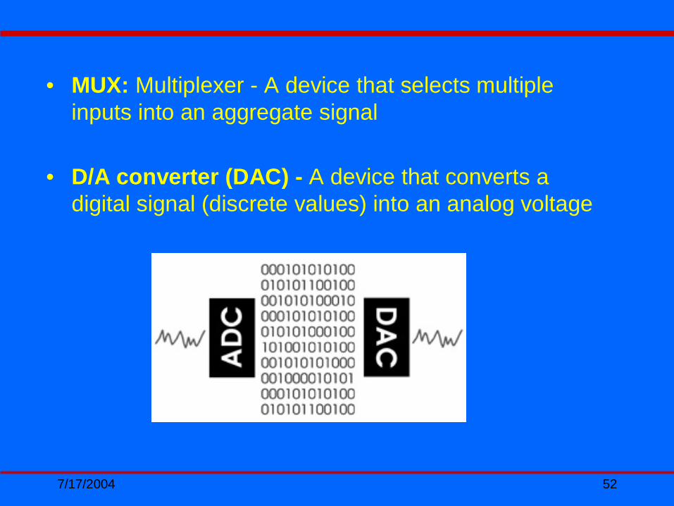
• MUX: Multiplexer - A device that selects multiple inputs into an aggregate signal
• D/A converter (DAC) - A device that converts a digital signal (discrete values) into an analog voltage
7/17/2004 53
• Peak. Extreme value of a varying quantity, measured from the zero or mean value. Also, a maximum spectral value. Peak times .707=RMS
• RMS or root-mean-square value. The square root of the time-averaged squares of a series of measurements. Refer to a textbook on electrical engineering. In the exclusive case of a sine wave, s, the RMS value, is 0.707 ´ the peak value. Peak = RMS x 1.414
• Averaging. Summing and suitably dividing several like measurements to improve accuracy or to lessen any asynchronies

7/17/2004 54
Testing Applications• Mil-Std testing
– (Sine, Random and Shock Applications)• SAE standards• Transportation crash simulation• Package testing• Production testing• Road load testing• Failure analysis• Environmental stress screening • Fatigue & fragility testing• Buzz, squeak & rattle (BSR)

7/17/2004 55
More Applications…• Product development & qualification• Accelerated life testing• Accelerated stress screening• Nebs (GR-63-core)•RTCA/DO-160 requirements

7/17/2004 56
Accelerated Life Testing
An activity during development of a new product. Prototypes are subjected to stress levels (including
vibration, usually random) that are much higher than those anticipated in the field. The purpose is to
identify failure-prone, marginally-strong elements by causing them to fail. Those elements are
strengthened and tests are continued at higher levels. Sometimes called test, analyze & fix testing
(TAAF) or highly accelerated life test (HALT).
7/17/2004 57
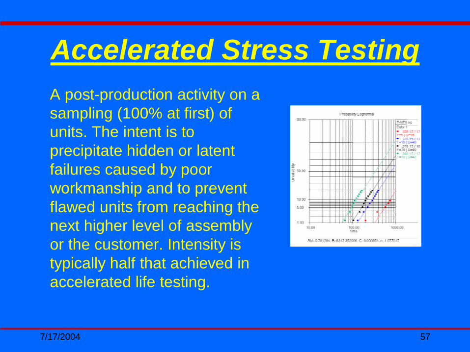
Accelerated Stress TestingA post-production activity on a sampling (100% at first) of units. The intent is to precipitate hidden or latent failures caused by poor workmanship and to prevent flawed units from reaching the next higher level of assembly or the customer. Intensity is typically half that achieved in accelerated life testing.

7/17/2004 58
Environmental Stress Screening (ESS)
A post-production process in which 100% of produced units are subjected to stresses more severe than anticipated in service. The object is to precipitate latent defects into recognizable failures, so that that particular unit does not proceed further in production nor reach the customer. Hass. Highly accelerated stress screening.

7/17/2004 59
Life Cycle Testing
A modern electronics production tool for precipitating latent defects such as poorly-soldered connections. Utilizes random vibration + rapid temperature ramping.
Subjecting products to stresses similar to those anticipatedin actual service while collecting engineering data related to life expectancy, reliability, specification compliance, or product improvements.
Usually aimed at determining the products' mean time between failures or MTBF stress screening.

7/17/2004 60
Reliability
The likelihood or probability that an equipment will "do its job" for a specified length of time (say 1000 hours) under specified circumstances (such as cycling in a specified manner over certain temperature limits, experiencing a particular vibration spectrum, etc.). Reliability defined in this way can be determined experimentally. Take 1000 units. Operate them under specified conditions. At the end of 1000 hours, how many are still operating correctly?
7/17/2004 61
Fragility Test
Expensive but highly useful dynamic tests of several samples (to account for variations in tolerances, material properties and manufacturing processes) at potentially destructive frequencies, to determine fragility.

7/17/2004 62
Random Vibration
One whose instantaneous magnitudes cannot be predicted. Adjective "Gaussian" applies if they follow the Gaussian distribution. May be broad-band, covering a wide, continuous frequency range, or narrow band, covering a relatively narrow frequency range. No periodic or deterministic components.

7/17/2004 63
Random on Random
Combined environment of broad band random with narrow band swept random bandwidths
Sine on Random
Combined environment of broad band random with discrete stationary or swept sine tones.

7/17/2004 64
An ultra-simple shock pulse, one that is never seen in the "real world" yet is often specified in test requirements. Such pulses contain much more low-frequency energy than do "real world" shock events. Such pulses are said to be "mathematically tractable". They have been studied to death.
Examples include the half-sine pulse, the square pulse, the triangular pulse, the trapezoid and the sawtooth. The first four, which are symmetrical, are being specified less with each passing year. Only thesawtooth is required in MIL-STD-810F.
Classical Shock Pulse

7/17/2004 65
Shock Pulse
Complex waveform: Time domain waveform with multiple frequencies and amplitudes. Seismic, Pyrotechnic event.
Shock pulse, haversine: A practical variation on the obsolete half-sine pulse, whose abrupt transitions at beginning and end cannot be achieved in test labs. Practical testing requires some rounding, and the result is called a haversine pulse. Another definition: an inverted cosine offset by half its amplitude. A continuous haversine resembles a sine wave.
7/17/2004 66
Bounce Test
A shaking of unrestrained (loose) cargo. The cargo is repeatedly thrown a short distance into the air and then falls onto the vibrating platform.
Impact Test (bump test)
A broad frequency range of structural responses is caused by a deliberate impact.
7/17/2004 67
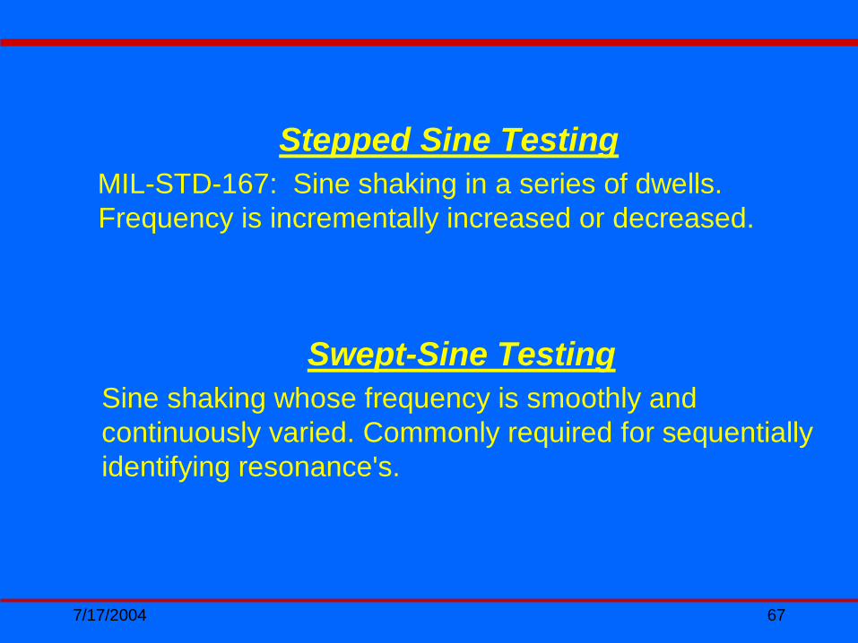
Stepped Sine TestingMIL-STD-167: Sine shaking in a series of dwells. Frequency is incrementally increased or decreased.
Swept-Sine TestingSine shaking whose frequency is smoothly and continuously varied. Commonly required for sequentially identifying resonance's.

7/17/2004 68
Vibration Basicsand Shaker Selection
7/17/2004 69
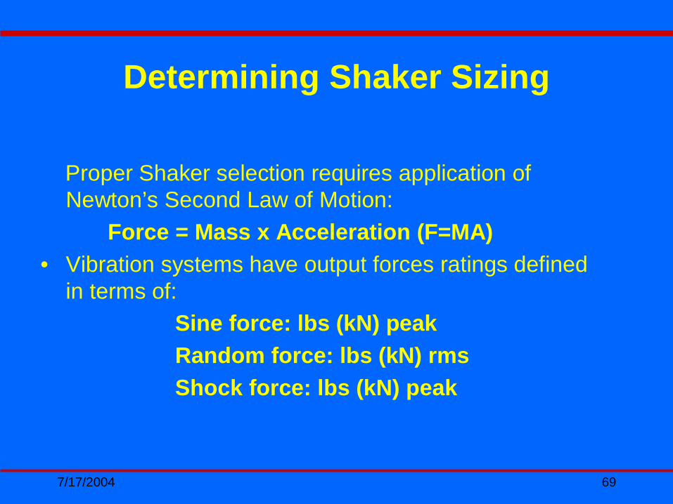
Determining Shaker Sizing
Proper Shaker selection requires application of Newton’s Second Law of Motion:
Force = Mass x Acceleration (F=MA)• Vibration systems have output forces ratings defined
in terms of:Sine force: lbs (kN) peakRandom force: lbs (kN) rmsShock force: lbs (kN) peak

7/17/2004 70
Suitability of a Specific Test System can be evaluated in terms of the following:
Force Requirement (lbf)• UUT + Fixture + Armature x G = F x 1.30= Desired Force
Shaker SystemMaximum Displacement• Determined by test environmentMaximum Velocity• Determined by test environment
Applying Newton’s Law In Shaker Selection

7/17/2004 71
• The mass value (M) in the initial formula of F = MA must include all moving masses attached to the shaker armature surface including the armature mass itself: shaker armature + head expander or slip plate with its driver bar + test specimen + specimen interface fixture, including bolts and bearing stiction if the system is driving a horizontal plate using hydrostatic bearings.
F=maDetermining Moving MASS

7/17/2004 72
Determining and Evaluating Mass
Test Articles, Slip Tables, Head Expanders and Fixtures
• Size, Mass and Frequency Response• Overturning Moment/Guidance Issues
(UUT+Fixture) x CG x G x Q= lbin• Slide Plate: L x W x PSI (14) x effective area= lbin• Desired Resonance:
Frequency x (L x W)/ 209000=Thickness

7/17/2004 73
Specimen Specifics
• Specimen Description• Specimen Test Mass• Specimen Dimensions• Specimen Center of Gravity (CG)• Specimen Mounting Considerations
In addition to your test specification, the following test article data is required to determine the appropriate system for your test requirements:

7/17/2004 74
Fixture Specifics
• Do your fixtures exist or will they require design and fabrication?
• What are or will be the approximate dimensions (estimate if necessary) of the fixturing?
• What is or will be the approximate mass (estimate if necessary) of the fixturing?
• Are there any mounting issues (bolt pattern, size)?• Will a head expander be required?
Test fixtures effect mass and resonance and must be considered carefully. The following concerns should be addressed in selecting a shaker system:

7/17/2004 75
• The maximum AccelerationAcceleration for the F = MA estimate is derived from the test specification:– for Sine vibration (G-peak)– for Random vibration (G-rms)– for Classical Shock pulses (G-peak)
• The operator must be cognizant of the maximum displacement and velocity of any given test parameter to insure they don’t exceed the systems capabilities
F=maTest Specifications
7/17/2004 76
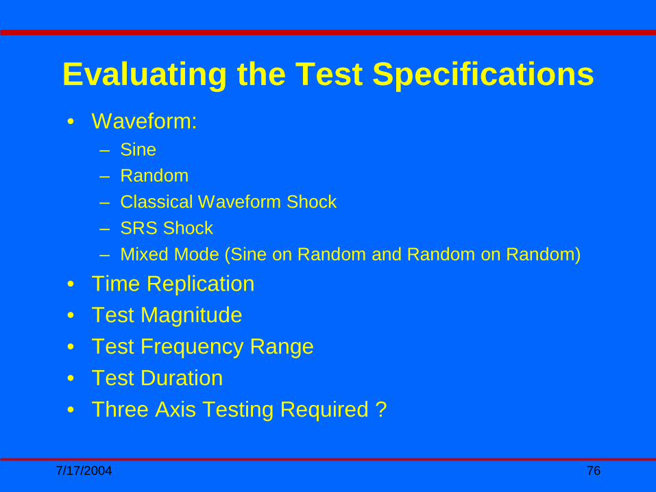
Evaluating the Test Specifications• Waveform:
– Sine– Random– Classical Waveform Shock– SRS Shock– Mixed Mode (Sine on Random and Random on Random)
• Time Replication• Test Magnitude• Test Frequency Range• Test Duration• Three Axis Testing Required ?

7/17/2004 77
Random vibration stated force ratings are determined with guidance of ISO 5344. ISO 5344 specifies use of a flat 20 Hz to 2000 Hz spectrum with a test load of three to four times the armature mass. This is done to achieve continuity of ratings between different manufacturers. By use of the non-resonant three to four time armature mass load the resonant frequency of the shaker armature under test typically will fall below 2000 Hz. This enables the system to gain free energy at the higher frequencies.
Understanding Random Vibration

7/17/2004 78
Typical “real life” Random tests don’t always have test loads of three to four times the armature weight and test input profiles are gaussian in nature rather than flat. Narrow band Random profiles that don’t excite the armature resonance and have test fixtures that are highly damped may require system de-rating of up to 30%.
Real World Random Vibration

7/17/2004 79
• Every mechanical structure has a resonant frequency, which may result in a significant dynamic force absorber at certain frequencies. This phenomena must be taken into account during the estimating process. The force rating defined by the manufacture is rated at the armature surface. If the test system has associated fixtures, head expanders, slip tables, etc. that act as force absorbers and have been defined as a control accelerometer locations, then the shaker may be over driven. It is always advisable to have monitor accelerometer attached to the armature surface to determine the “true force” that is being achieved.
Effects of Resonance

7/17/2004 80
F=maCalculating Required Force
• Multiply the TOTAL MOVING MASS by the ACCELERATION (G) LEVEL determined by your test specification
• Include a safety margin for transmissibility, etc.
• Use our Microsoft Excel® Shaker Selection Calculator (next slide) for determining the minimum system force rating requirements needed for your application
• It is always recommended that you verify your calculations with a sales engineer prior to purchasing a system
7/17/2004 81
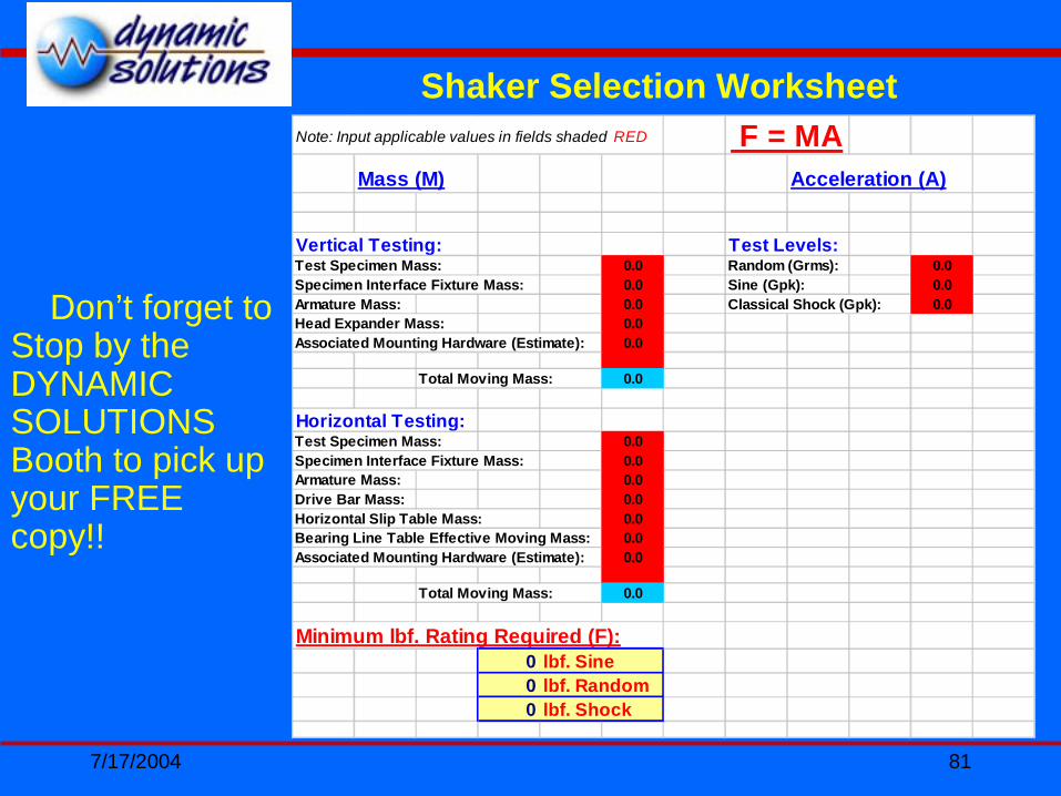
Note: Input applicable values in fields shaded RED F = MAMass (M) Acceleration (A)
Vertical Testing: Test Levels:Test Specimen Mass: 0.0 Random (Grms): 0.0Specimen Interface Fixture Mass: 0.0 Sine (Gpk): 0.0Armature Mass: 0.0 Classical Shock (Gpk): 0.0Head Expander Mass: 0.0Associated Mounting Hardware (Estimate): 0.0
Total Moving Mass: 0.0
Horizontal Testing:Test Specimen Mass: 0.0Specimen Interface Fixture Mass: 0.0Armature Mass: 0.0Drive Bar Mass: 0.0Horizontal Slip Table Mass: 0.0Bearing Line Table Effective Moving Mass: 0.0Associated Mounting Hardware (Estimate): 0.0
Total Moving Mass: 0.0
Minimum lbf. Rating Required (F):0 lbf. Sine 0 0
0 lbf. Random 0 0
0 lbf. Shock 0 0
Shaker Selection Worksheet
Don’t forget to Stop by the DYNAMIC SOLUTIONS Booth to pick up your FREE copy!!
7/17/2004 82
“Reliable and AffordableShaker Systems”
GOOD VIBRATIONSGOOD VIBRATIONSWith a THREE YEAR PARTS
WARRANTY!!