Embed Size (px)
Citation preview

Application ReportSPRAAI7B–July 2008
Understanding the DaVinci ResizerXiangdong Fu ..................................................................................................................................
ABSTRACTThe image-scaling operation is one of the most commonly used video and imagingprocessing functions. The resizer hardware module in the DaVinci™ video processingsubsystem (VPSS) provides the scaling capability in hardware, therefore, off-loadingthe system for other processing tasks. To achieve good video quality while maintaininggood overall system performance, a better understanding of the hardware and thealgorithm behind it is necessary.
This application report intends to help application developers better understand theresizer. First, several commonly used image-scaling algorithms are discussed andcompared, including bi-linear and by-cubic interpolation, and the polyphase filteringalgorithm. Second, an overview of the resizer hardware is given. This includes blockdiagram, features, and restrictions with the main focus on the algorithms behind thehardware. Third, several aspects of the resizer programming are discussed in detail,including constant input output sizing, calculation of filter coefficients, and registerprogramming pitfalls. The Linux™ driver for resizer is then described, followed byseveral usage examples.
This application report contains project code that can be downloaded from these links.http://www-s.ti.com/sc/techlit/sprc381.gz and http://www-s.ti.com/sc/techlit/sprc382.gz.The example files attached are created in Linux and are to be extracted, built andexecuted in Linux. Please use tar -xzf file_name to uncompress the archives in Linux.
Contents1 Overview ............................................................................................. 22 The Scaling Algorithm.............................................................................. 23 Overview of the Resizer Hardware and Algorithm ............................................. 94 Programming the Resizer ........................................................................ 165 The Resizer Driver ................................................................................ 266 Programming Examples.......................................................................... 287 References......................................................................................... 29
List of Figures
1 Bi-Linear Interpolation.............................................................................. 32 Impulse Response of Bi-Linear Interpolation ................................................... 33 Amplitude Spectra of Bilinear Interpolation Kernel ............................................. 34 Bi-Cubic Interpolation .............................................................................. 35 Impulse Response of Bi-Cubic Interpolation .................................................... 46 Amplitude Spectra of the of the Keys Bi-Cubic Interpolation Kernel......................... 47 Spectrum of the Original Signal................................................................... 58 Spectrum of the x Down-Sampled Signal Without LPF ....................................... 59 Apply LPF Before Down-Sampling ............................................................... 510 Spectrum of the LPF and the Original Signal .................................................. 511 Spectrum of the x Down-Sampled Signal With Low-Pass Filtering Before
Down-Sampling ..................................................................................... 612 Spectrum of the Original Signal................................................................... 613 Spectrum of the 2x Up-Sampled Signal Without LPF ......................................... 6
SPRAAI7B–July 2008 Understanding the DaVinci Resizer 1Submit Documentation Feedback

1 Overview
2 The Scaling Algorithm
Overview www.ti.com
14 Apply LPF After Up-Sampling..................................................................... 615 The Spectrum of the Up-Sampled Signal and the LPF ....................................... 716 Spectrum of the 2x Up-Sampled Signal With Low-Pass Filtering ........................... 717 Re-Sampling by N/M With Low-Pass Filtering.................................................. 718 Poly-Phase Filter Architecture for M/N Re-Sampling .......................................... 819 Resizer Block Diagram............................................................................. 920 Resizer Processing Flow......................................................................... 1021 Arrangement of Filter Coefficients .............................................................. 1222 Resizing Stage 1: Up-Sampling to 1/8 Pixel Location........................................ 1323 Resizing Stage 2: Interpolation to RSZ/256 Pixel Location ................................. 1424 Filter With Luma................................................................................... 1525 Bilinear Interpolation .............................................................................. 1526 High Pass Gain as a Function of Absolute High Passed Luma............................. 1627 Usage Information of the calccoeff Utility ...................................................... 1928 3-Layer Architecture of the RSZ Module....................................................... 26
List of Tables
1 Polyphase Filter Coefficients...................................................................... 92 Storage of Polyphase Filter Coefficients ....................................................... 133 Pixel Locations vs. Phases ...................................................................... 134 Resizer Register Map............................................................................. 24
The VPSS resizer is essentially a hardware implemented polyphase filter for image scaling operation; itcan scale from X to 4X.
The resizer can operate on either interleaved Y/Cb/Cr 4:2:2 data or separated single color plane, forexample, gray scale data, separated RGB 8:8:8 data or planar Y/Cb/Cr data.
From X to X, the resizer uses 4-phase 7-tap polyphase filter architecture. From X to 4X, the resizer uses8-phase 4-tap polyphase filter architecture. The choice of the filter type is done automatically by hardwarebased on the scaling ratio and cannot be changed by software.
The resizer operates in two stages: the horizontal stage and the vertical stage. After horizontal processing,intermediate data are stored in a line buffer before vertical processing. The line buffer must store 4 lines ofdata for scaling ration between X to 4X and 7 lines of data for scaling ration between X and X. Due to thisrequirement and the size of the line buffer, for X to X scaling, the maximum output line size cannot bemore than 640 pixels per line; for X to 4X scaling, the output size cannot be more than 1280 pixels. This istrue for both interleaved 16-bit per pixel Y/Cb/Cr 4:2:2 data and 8-bit per pixel planar data.
To understand the operation of the resizer, we first take a look at the algorithm behind it. The basics ofscaling are covered in textbooks on multi-rate systems, and it is out of the scope of this application report,which only illustrates principles.
There are several commonly used algorithms for image scaling.• Bi-linear interpolation• Bi-cubic interpolation• Nyquist low-pass filtering
For upscaling, any of the three methods above can be used. For downscaling, to avoid the aliasing effect,data is usually low-pass filtered before down-sampled.
DaVinci is a trademark of Texas Instruments.Linux is a trademark of Linux Torvalds in the U.S. and other countries.MontaVista is a registered trademark of MontaVista Software, Inc.All other trademarks are the property of their respective owners.
2 Understanding the DaVinci Resizer SPRAAI7B–July 2008Submit Documentation Feedback

2.1 Bi-Linear Interpolation
Xi Xi+1
α
X’i+α
1-α
X' = (1 - ) x + xi+a i i+1a a (1)
-1 -0.5 0 0.5 10
0.2
0.4
0.6
0.8
1
0 0.5 1 1.5 2 2.5 3 3.50
2
4
6
8
2.2 Bi-Cubic Interpolation
Xi Xi+1
α
X’i+α
1-αXi-1
1+α
Xi+2
2-α
www.ti.com The Scaling Algorithm
Bi-linear interpolation uses the two nearest pixels from the input image to interpolate the missing pixel inthe output image. This is usually used for upscaling. Figure 1 shows an example of bi-linear interpolation.
Figure 1. Bi-Linear Interpolation
If we look at the bi-linear interpolation from a filter point of view, the impulse response function of the filteris shown in Figure 2.
Figure 2. Impulse Response of Bi-Linear Interpolation
Figure 3. Amplitude Spectra of Bilinear Interpolation Kernel
For downscaling, due to the aliasing effects, only the low-pass filtering method normally is used. Bi-linearand bi-cubic interpolation methods normally are used for upscaling.
Bi-cubic interpolation uses four neighboring pixels in the input image to interpolate the missing pixels inthe output image.
Figure 4. Bi-Cubic Interpolation
SPRAAI7B–July 2008 Understanding the DaVinci Resizer 3Submit Documentation Feedback

x' = u(1 + ) x + u( )x +u(1 - a) x + u(2 - ) xi + i-1 i i + 1 i + 2a a a aa (2)
( )
3 53 2s s 1 0 s 1
2 2
1 53 2s s 4 s 2 1 s 2
2 2
0 s 2
u s
ì
- + £ £ï
ï
ï= - + - + £ £í
ï
ï >
ï
î (3)
-2 -1.5 -1 -0.5 0 0.5 1 1.5 2
-0.2
0
0.2
0.4
0.6
0.8
0 pi/8 pi/4 3pi/8 pi/20
1
2
3
4
5
6
7
8
2.3 Low-Pass Filtering
The Scaling Algorithm www.ti.com
In Equation 2, is the bi-cubic interpolation kernel. There is a family of bi-cubic interpolation kernels. One ofthe most commonly used is designed by Keys in [1], as shown below.
The impulse response and the amplitude spectra of bi-cubic interpolation is shown in Figure 5 andFigure 6.
Figure 5. Impulse Response of Bi-Cubic Interpolation
Figure 6. Amplitude Spectra of the of the Keys Bi-Cubic Interpolation Kernel
According to signal processing theories, data must be low-pass filtered before up-sampled ordown-sampled. This is to remove the aliasing effect caused by the re-sampling process. The requirementfor the low-pass filter (LPF) depends on the scaling factor, which is discussed in detail below. The mostcommonly used computational efficient implementation of the LPF is the polyphase architecture. Inaddition, both bi-linear and bi-cubic interpolations can be implemented as a low-pass filter.
4 Understanding the DaVinci Resizer SPRAAI7B–July 2008Submit Documentation Feedback
2.3.1 Down-Sampling by M
1fs
2p
æ öç ÷- -ç ÷ç ÷ç ÷è ø
0 1fs
2p
æ öç ÷ç ÷ç ÷ç ÷è ø
- /2( fs')p ½p/2(-½fs’)0
fs’ = fs½
Low-pass Filter Down-sampler
M
Original Signal
LPF Filter
-½ (p ¼fs)- (-½fp s’) 0 ½ (p ¼fs) p(½fs’)
Fs’ = ½ fs and the cut-off frequency of the LPF is ¼fs
www.ti.com The Scaling Algorithm
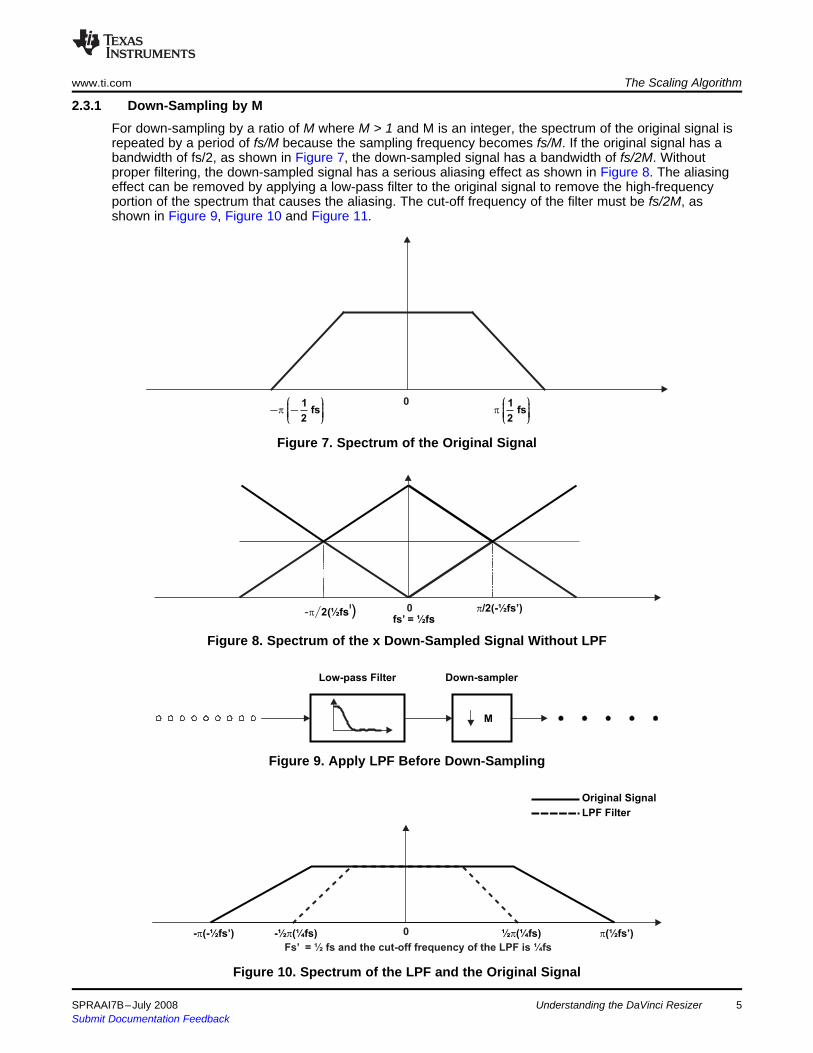
For down-sampling by a ratio of M where M > 1 and M is an integer, the spectrum of the original signal isrepeated by a period of fs/M because the sampling frequency becomes fs/M. If the original signal has abandwidth of fs/2, as shown in Figure 7, the down-sampled signal has a bandwidth of fs/2M. Withoutproper filtering, the down-sampled signal has a serious aliasing effect as shown in Figure 8. The aliasingeffect can be removed by applying a low-pass filter to the original signal to remove the high-frequencyportion of the spectrum that causes the aliasing. The cut-off frequency of the filter must be fs/2M, asshown in Figure 9, Figure 10 and Figure 11.
Figure 7. Spectrum of the Original Signal
Figure 8. Spectrum of the x Down-Sampled Signal Without LPF
Figure 9. Apply LPF Before Down-Sampling
Figure 10. Spectrum of the LPF and the Original Signal
SPRAAI7B–July 2008 Understanding the DaVinci Resizer 5Submit Documentation Feedback

1fs'
2p
æ öç ÷- -ç ÷ç ÷ç ÷è ø
01
fs'2
p
æ öç ÷ç ÷ç ÷ç ÷è ø
fs’ = ½ fs and the cut-off frequency of the LPF is ¼fs or ½fs’
2.3.2 Up-Sampling by N
1fs
2p
æ öç ÷- -ç ÷ç ÷ç ÷è ø
0 1fs
2p
æ öç ÷ç ÷ç ÷ç ÷è ø
0-- (-P ½fs’) -½ (-p ¼fs’) ½ (¼p fs’) p(½fs’)
fs’ = 2fs
N
Up-Sampler -Low-Pass Filter
The Scaling Algorithm www.ti.com
Figure 11. Spectrum of the x Down-Sampled Signal With Low-Pass Filtering Before Down-Sampling
For up-sampling (digital zoom) by a ratio of N where N > 1 and N is an integer, the spectrum of theoriginal signal is repeated by a period of fs. If the original signal has a bandwidth of fs, as shown inFigure 12, without proper filtering, the up-sampled signal has a serious aliasing effect as shown inFigure 13. The aliasing effect can be removed by applying a low-pass filter to the up-sampled signal toremove the high frequency portion of the spectrum that causes the aliasing. The cut-off frequency of thefilter must be fs/2, as shown in Figure 14, Figure 15 and Figure 16.
Figure 12. Spectrum of the Original Signal
Figure 13. Spectrum of the 2x Up-Sampled Signal Without LPF
Figure 14. Apply LPF After Up-Sampling
Understanding the DaVinci Resizer6 SPRAAI7B–July 2008Submit Documentation Feedback

Original Sign
LPF Filter
- (-½fs’)p -½ (-p ¼fs’) ½p(¼fs’) p(½fs’)
The LPF has a DC gain of 2 and a cut-off frequency of ¼fs
0
- (-½fs’)p -½ (-p ¼fs’) ½ (p ¼fs’) - (-½fs’)p
fs’ = 2fs and the LPF’s cut-off frequency is ¼fs’ and its gain is 2
0
2.3.3 Re-Sampling by a Factor of N/M
Up-Sampler Low-Pass Filter Down-Sampler
N M
www.ti.com The Scaling Algorithm
Figure 15. The Spectrum of the Up-Sampled Signal and the LPF
Figure 16. Spectrum of the 2x Up-Sampled Signal With Low-Pass Filtering
To avoid aliasing in more general cases in which the re-sampling factor is a rational N/M rather than aninteger, low-pass filter must be applied to the up-sampled data before they are down-sampled, as shownin Figure 17 below.
Figure 17. Re-Sampling by N/M With Low-Pass Filtering
The low-pass filter has a DC gain of N and a cut-off frequency of fs/2max(N, M).
SPRAAI7B–July 2008 Understanding the DaVinci Resizer 7Submit Documentation Feedback

2.3.4 Poly-Phase Architecture for LPF Implementation
MH (z)0 N
N
N
N
N
x(n) y(h)
H (z)1
H (z)2
H (z)3
H (z)N-1 Z
-1
Z-1
Z-1
Z-1
( ) ( )
L-1-nH z h n z
n=0å
(4)
( ) ( )
N-1-mH z = H z zm
m=0å
(5)
( ) ( )
Lm -nNH z = h nN + m zmn=0å
(6)
The Scaling Algorithm www.ti.com
To reduce the number of computations required for the re-sampling process, the polyphase filterarchitecture has been widely used. Figure 18 shows the polyphase filter architecture for M/N re-samplingoperation.
Figure 18. Poly-Phase Filter Architecture for M/N Re-Sampling
In Figure 18, H(z) is the z-transform of the impulse response of the LPF.
Where L is the length of the FIR filter. H(z) also can be re-written as:
Where
Where Lm = L/N, assuming L is a multiple of N. If not, zeros are padded to the coefficients to make L amultiple of N.
Understanding the DaVinci Resizer8 SPRAAI7B–July 2008Submit Documentation Feedback

3 Overview of the Resizer Hardware and Algorithm
3.1 Block Diagram
Read
Buffer
Memory
(VPSS)
Preview
Engine/
CCDC
SDRAM/
DDRAMLine Buffer
Resizer
Register
SettingsWrite
Buffer
Memory
(VPSS)
Dma Clock
Configuration Bus/
MMR Clock
and InterfaceSDRAM/
DDRAM
www.ti.com Overview of the Resizer Hardware and Algorithm
Basically, this means h(n) is divided h(n) into n-phases, as shown in Table 1:
Table 1. Polyphase Filter Coefficients
Original filter coefficients: h(0), h(1), h(2), h(3), …… h(L-1)Phase-0: h(0) h(N) h(2N) … h(Lm(–1))Phase-1: h(1) h(N+1) h(2N+1) … h(Lm(–1)+1)Phase-2: h(2) h(N+2) h(2N+1) … h(Lm(–1)+2)Phase-2: h(3) h(N+3) h(2N+3) … h(Lm(–1)+3). .. .. .Phase-–1: h(–1) h(2N-1) h(3N-1) … h(Lm(–1)+3)
The 1:N up-sampling basically inserts N–1 zeros between each neighboring samples. This means onlyone of the N phases of the filter is used to calculate the output sample before down-sampling because theother N–1 phases all output zero due to the up-sampling. In addition, because the M:1 down-samplingdrops N-1 samples in every M sample, only every Mth output sample needs to be calculated. Altogether,significant amount of computations can be saved.
The resizer module performs either up-sampling or down-sampling on image/video data. The input sourcecan be either the preview engine/CCDC or SDRAM/DDRAM, and the output is sent to theSDRAM/DDRAM. Figure 19 shows the high level block diagram of the resizer module.
Figure 19. Resizer Block Diagram
SPRAAI7B–July 2008 Understanding the DaVinci Resizer 9Submit Documentation Feedback

Horizontal
Resizer
YCbCr 422
2 Colors/Pix
8-Bit/Color
YCbCr 422
2 Colors/Pix
8-Bit/ColorLuma
Enhancement
YCbCr 422
2 Colors/Pix
8-Bit/ColorVertical
Resizer
YCbCr 422
2 Colors/Pix
8-Bit/Color
Line Buffer
3 Lines x 1280 x 16-bit
or 6 Lines x 640 x 16-bit
Vertical Coef Storage
8 Phases x 4 Taps
or 4 Phases x 7 Taps
Horizontal Coef Storage
8 Phases x 4 Taps
or 4 Phases x 7 Taps
3.2 Features supported
Overview of the Resizer Hardware and Algorithm www.ti.com
Figure 20. Resizer Processing Flow
The resizer module performs horizontal resizing, then vertical resizing. In between, there is an optionalhorizontal luma edge enhancement filter. Processing flow and data precision at each stage are shown inFigure 20. The line buffer is functionally either 3 lines of 1280 pixels x 16-bit or 6 lines of 640 pixels x16-bit, depending on the vertical resizing being 4-tap or 7-tap mode. This puts the limitation on themaximum output size of either 1280 pixels for 4-tap filter or 640 pixels for 7-tap filter.
The resizer module can accept input image/video data from either the Previewer/CCDC or the externalDDRAM. The output of the resizer module is sent to the DDRAM. The resizer module is programmed viaits registers that are accessible by the ARM-9 processor. The following features are supported by theresizer module.• Input from either the Previewer/CCDC (on-the-fly processing) or from external SDRAM/DDRAM.• Support for x - 4x sampling with sampling ratio equals to 256/N, where N ranges from 64 to 1024.
– Bi-cubic interpolation (4-tap horizontal, 4-tap vertical) can be implemented with the programmablefilter coefficients
– 4-tap 8 phases of the filter coefficients are supported for sampling rate ½x– 4x– 7-tap 4 phases of the filter coefficients are supported for sampling rate x- x– Optionally select bi-linear interpolation for the chrominance components for up-sampling .– Can be performed on-the-fly if the input source is the Previewer/CCDC.
• Support for resizing either YUV 422 packed data (16-bits) or color separate data (assumed to be 8-bitdata) that is contiguous. The input source for the color separate data should be the external DDRAM
• Independently programmable resizing factors for the horizontal and vertical directions.• Optional programmable luminance sharpening after the horizontal resizing and before the vertical
resizing step.
Understanding the DaVinci Resizer10 SPRAAI7B–July 2008Submit Documentation Feedback

3.3 Restrictions
3.4 The Resizing Algorithm for Luminance Data
www.ti.com Overview of the Resizer Hardware and Algorithm
• The resizer does not support output size of more than 1280 pixels/line for resizing ratio between ½x –4x; or more than 640 pixels/line for resizing ratio between ¼x – ½x. For Y/Cb/Cr 4:2:2 data, this is dueto the size limitation of the line buffer, which is 7680 bytes. Due to hardware implementation, thisrestriction also holds for 8-bit planar data from DDR memory.
• For input from Previewer/CCDC, the throughput of the horizontal stage cannot exceed resizer_clock/2Mpixels/second. For example, if the resizer_clock = 150 MHz, the throughput is less than 75Mpixels/second. This implies that no up-scaling can be achieved for input that has a pixel clock of 75MHz.
• The resizer does not support input format other than Y/Cb/Cr 4:2:2 interleaved or color separated 8-bitplanar data.
• When the input data is color separate, the source can only be SDRAM/DDRAM and cannot be thePreviewer/CCDC.
• When the input source is the preview engine, the maximum input width cannot be greater than 1280due to the preview engine’s maximum output width restriction of 1280.
• The number of bytes per output line written to DDRAM must be a multiple of 16 bytes when verticalupsizing is performed.
• The resizer hardware does not perform edge interpolation. For horizontal resizing, several pixels ateach edge are cropped. For vertical resizing, several lines at each edge are cropped. The relationshipof input, output size, and the resizing ratio is discussed in detail below.
The resizer module has the ability to up-sample or down-sample image data with independent resizingfactors in the horizontal and vertical directions (HRSZ and VRSZ). Because the same re-samplingalgorithm is applied in both the horizontal and vertical directions, for the rest this section, the horizontaldirection is used in describing the re-sampling algorithm, and RSZ is used to refer to the resizing factor.
The RSZ parameters can range from 64 to 1024, which gives a re-sampling range of x to 4x (256/RSZ).There are 32 programmable coefficients available for the horizontal direction and another 32programmable coefficients for the vertical direction. The 32 programmable coefficients are arranged aseither 4-taps & 8-phases for the resizing range of x ~ 4x (RSZ = 64 ~ 512) or 7-taps & 4-phases for aresizing range of x ~ x (RSZ = 513 ~ 1024).
Please note the following two important facts about the resizer:• The filter type (4-phase or 8-phase) is not software programmable. It is solely determined by
HARDWARE based on the value of the RSZ.• The horizontal and vertical stages are totally INDEPENDENT with different RSZ factors and different
coefficients. Hence, horizontal filter can be 4-phase and vertical filter can be 8-phase and vise visa.
SPRAAI7B–July 2008 Understanding the DaVinci Resizer 11Submit Documentation Feedback

0.5x to 4x 0.25x to ~0.5xFilter
CoefficientPhase Tap Phase Tap
0 0 0
1 1 1
2 2 2
3
0
3 3
4 0 4
5 1 5
6 2 6
7
1
3
0
Not Used
8 0 0
9 1 1
10 2 2
11
2
3 3
12 0 4
13 1 5
14 2 6
15
3
3
1
Not Used
16 0 0
17 1 1
18 2 2
19
4
3 3
20 0 4
21 1 5
22 2 6
23
5
3
2
Not Used
24 0 0
25 1 1
26 2 2
27
6
3 3
28 0 4
29 1 5
30 2 6
31
7
3
3
Not Used
Overview of the Resizer Hardware and Algorithm www.ti.com
Figure 21 shows the arrangement of the 32 filter coefficients. Each tap is arranged in a S10Q8 format(signed value of 10-bits with 8 of them being the fraction).
Figure 21. Arrangement of Filter Coefficients
Understanding the DaVinci Resizer12 SPRAAI7B–July 2008Submit Documentation Feedback
Starting Input Pixel
Starting Phase (0-7)
Input
Pixel 1
Input
Pixel 2
Input
Pixel 3
Input
Pixel 4
Input
Pixel 5
Input
Pixel n
Interpolated Pixels At 1/8 Pixel Locations
www.ti.com Overview of the Resizer Hardware and Algorithm
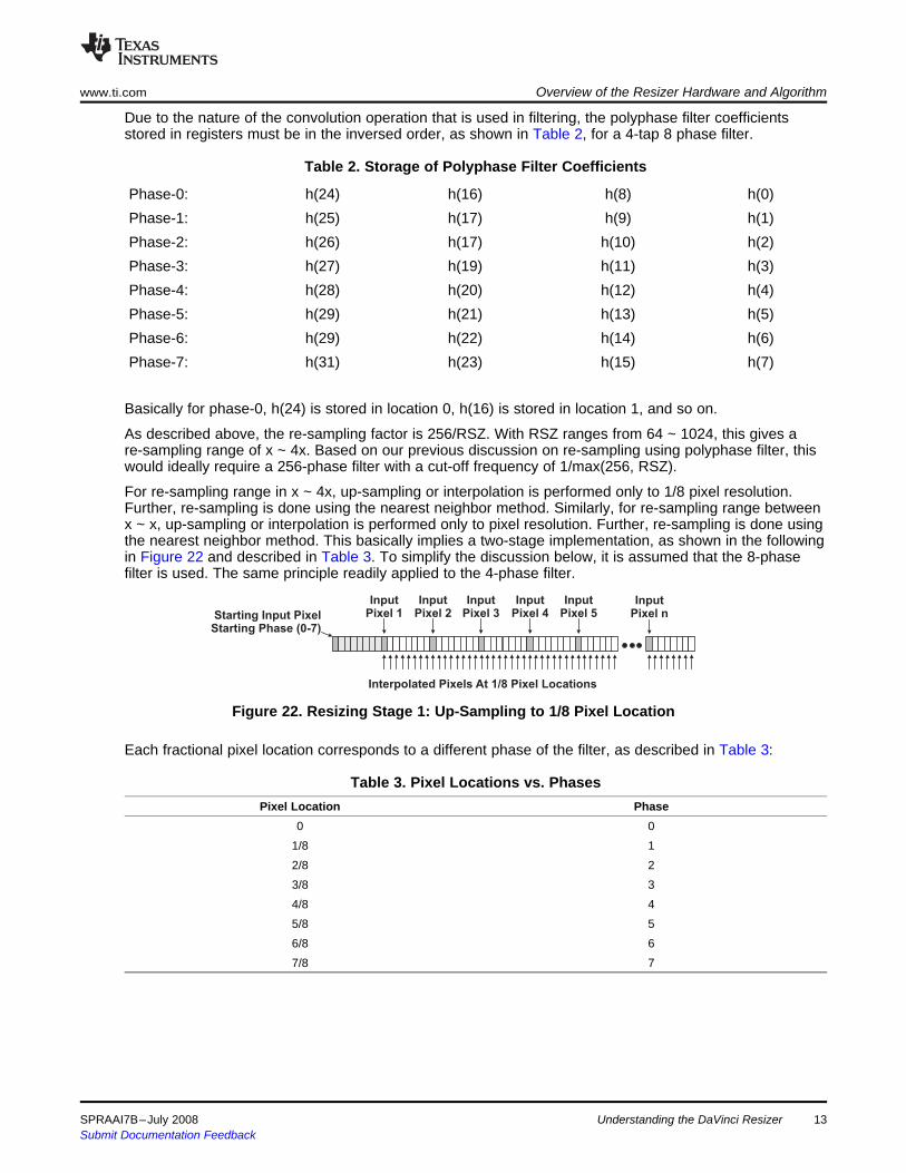
Due to the nature of the convolution operation that is used in filtering, the polyphase filter coefficientsstored in registers must be in the inversed order, as shown in Table 2, for a 4-tap 8 phase filter.
Table 2. Storage of Polyphase Filter Coefficients
Phase-0: h(24) h(16) h(8) h(0)Phase-1: h(25) h(17) h(9) h(1)Phase-2: h(26) h(17) h(10) h(2)Phase-3: h(27) h(19) h(11) h(3)Phase-4: h(28) h(20) h(12) h(4)Phase-5: h(29) h(21) h(13) h(5)Phase-6: h(29) h(22) h(14) h(6)Phase-7: h(31) h(23) h(15) h(7)
Basically for phase-0, h(24) is stored in location 0, h(16) is stored in location 1, and so on.
As described above, the re-sampling factor is 256/RSZ. With RSZ ranges from 64 ~ 1024, this gives are-sampling range of x ~ 4x. Based on our previous discussion on re-sampling using polyphase filter, thiswould ideally require a 256-phase filter with a cut-off frequency of 1/max(256, RSZ).
For re-sampling range in x ~ 4x, up-sampling or interpolation is performed only to 1/8 pixel resolution.Further, re-sampling is done using the nearest neighbor method. Similarly, for re-sampling range betweenx ~ x, up-sampling or interpolation is performed only to pixel resolution. Further, re-sampling is done usingthe nearest neighbor method. This basically implies a two-stage implementation, as shown in the followingin Figure 22 and described in Table 3. To simplify the discussion below, it is assumed that the 8-phasefilter is used. The same principle readily applied to the 4-phase filter.
Figure 22. Resizing Stage 1: Up-Sampling to 1/8 Pixel Location
Each fractional pixel location corresponds to a different phase of the filter, as described in Table 3:
Table 3. Pixel Locations vs. PhasesPixel Location Phase
0 01/8 12/8 23/8 34/8 45/8 56/8 67/8 7
SPRAAI7B–July 2008 Understanding the DaVinci Resizer 13Submit Documentation Feedback

x(n) = pixel_start + phase_start / 8 + n * step_size (7)
p(n) = round (x(n) * 8 + 0.5) /8 (8)
Starting Input Pixel
Starting Phase (0-7)
Input
Pixel 1
Input
Pixel 2
Input
Pixel 3
Input
Pixel 4
Input
Pixel 5
Input
Pixel n
Output
Pixels
1
Output
Pixels
2
Output
Pixels
3
Output
Pixels
4
Output
Pixels
5
Output
Pixels
m
Interpolated Pixels At 1/8 Pixel Locations
3.5 The Resizing Algorithm for Chrominance Data
Overview of the Resizer Hardware and Algorithm www.ti.com
The second stage produces output samples based on the value of its nearest neighbor at 1/8 resolutionpixel locations. The location of Nth output sample is determined by Equation 7:
Where:
step_size = RSZ/256
pixel_start identifies the location of the first pixel.
phase_start identifies the location of the phase (0 – 7).
Therefore, the location of its nearest neighbor is determined by rounding x(n) to the closest 1/8 pixellocation.
Figure 23. Resizing Stage 2: Interpolation to RSZ/256 Pixel Location
The above description portrays only an algorithmic view of the resizer for easy understanding. Actualhardware implementation varies in certain aspects. Refer to the TMS320DM644x DMSoC VideoProcessing Front End (VPFE) User's Guide (SPRUE38) for more details.
The resizer offers two possible operations for processing of chrominance data (chroma), which is 2:1down-sampled with respect to luminance data (luma):1. Filtering with luma for down-sampling, or2. Bi-linear interpolation for up-sampling
Because this feature is software programmable, hardware does not automatically switch between case 1and 2 based on the value of RSZ. It is the application’s responsibility to ensure the correct operation isapplied.
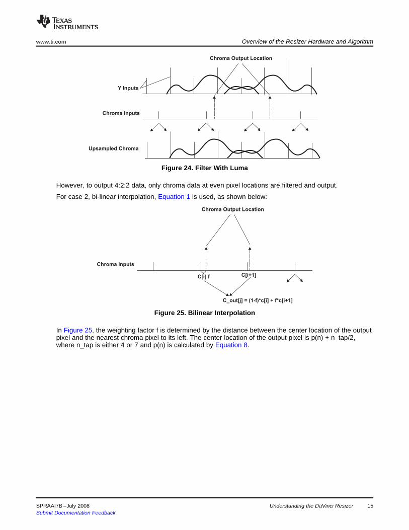
For case 1, filtering with luma, the same filter is applied to both luma and chroma data. Because the inputformat is 4:2:2, Cb and Cr data are up-sampled (duplicated) before the filter is applied, as shown below:
Original data (4:2:2):
cb0:y0:cr0:y1:cb1:y2:cr1:y3:cb2:y4:cr2:y5Chroma up-sampled (4:4:4):
cb0:cr0:y0:cb0:cr0:y1:cb1:cr1:y2:cb1:cr1:y3:cb2:cr2:y4:cb2:cr2:y5
Understanding the DaVinci Resizer14 SPRAAI7B–July 2008Submit Documentation Feedback
Chroma Output Location
Y Inputs
Chroma Inputs
Upsampled Chroma
Chroma Output Location
Chroma Inputs
C[i] f C[i+1]
C_out[j] = (1-f)*c[i] + f*c[i+1]
www.ti.com Overview of the Resizer Hardware and Algorithm
Figure 24. Filter With Luma
However, to output 4:2:2 data, only chroma data at even pixel locations are filtered and output.
For case 2, bi-linear interpolation, Equation 1 is used, as shown below:
Figure 25. Bilinear Interpolation
In Figure 25, the weighting factor f is determined by the distance between the center location of the outputpixel and the nearest chroma pixel to its left. The center location of the output pixel is p(n) + n_tap/2,where n_tap is either 4 or 7 and p(n) is calculated by Equation 8.
SPRAAI7B–July 2008 Understanding the DaVinci Resizer 15Submit Documentation Feedback

3.6 The Edge Enhancement Algorithm
GAIN
Hpgain
Slope =
SLOP
CORE
|HPF(Y)|
4 Programming the Resizer
4.1 Consistent Input and Output Sizing
iw = (32 * sph + (ow -1) * hrsz + 16) >> 8 + 7
ih = (32 *spv + (oh - 1) * vrsz + 16) >> 8 + 4 (9)
iw = (64 * sph + (ow - 1) * hrsz + 32) >> 8 + 7
ih = (64 * spv + (oh - 1) * vrsz + 32) >> 8 + 7 (10)
Programming the Resizer www.ti.com
Edge enhancement can be optionally applied to the horizontally resized luminance component before theoutput of the horizontal stage is sent to the line memories and the vertical stage. Either a 3-tap or a 5-taphorizontal high-pass filter can be selected to use in the luminance enhancement as shown below. If theedge enhancement is selected, the two left-most and two right-most pixels in each line are not output tothe line memories and the vertical stage. The output width specified in the OUT_SIZE register is the finaloutput width, up to 1280 when vertical 4-tap mode is used, and up to 640 pixels when the vertical 7-tapmode is used. When the edge enhancement is enabled, the horizontal resizer output width =OUT_SIZE.horz + 4.
The edge-enhancement algorithm is as follows.• HPF(Y) = Y convolved with { [–0.5, 1, –0.5] or [–0.25, –0.5, 1.5, –0.5, –0.25] }• Saturate HPF(Y) between –256 and +255• hpgain = ( |HPF(Y)| – CORE ) * SLOP• Saturate hpgain between 0 and GAIN• Y’ = Y + (HPF(Y) * hpgain + 8) >> 4• Saturate Y’ between 0 and 255
Basically, the high pass gain is computed by mapping the absolute value of high passed luma with thefollowing curve as shown in Figure 26.
Figure 26. High Pass Gain as a Function of Absolute High Passed Luma
One of the major pitfalls in resizer programming is consistent input and output size with regard to thevalue of RSZ, for both horizontal and vertical directions. Inconsistent values can cause the hardware tohang indefinitely and require a VPSS reset to get it back to default state. Because this also resets allVPSS modules, it is clearly not a desirable solution. To ensure consistent sizing, the input and output sizeand the RSZ should satisfy the equations below:
For 4-tap filters:
For 7-tap filters:
16 Understanding the DaVinci Resizer SPRAAI7B–July 2008Submit Documentation Feedback

( )
( )
in_width-4 * 256hrsz = floor
ow -1
in_height -4 * 256vrsz = floor
oh-1
æ ö
ç ÷ç ÷
è ø
æ ö
ç ÷ç ÷
è ø (11)
( )
( )
in_width-7 * 256hrsz = floor
ow -1
in_height -7 * 256vrsz = floor
oh-1
æ ö
ç ÷ç ÷
è ø
æ ö
ç ÷ç ÷
è ø (12)
www.ti.com Programming the Resizer
Where iw and ih are input width and height, ow and oh are output width and height respectively; hrsz andvrsz are horizontal and vertical resizing factors; sph and spv are horizontal and vertical starting phases.
WARNINGEquation 9 and Equation 10 must be satisfied for the resizer towork properly. iw and ih values greater or smaller than required bythe equations may hang the hardware.
Equation 9 and Equation 10 are given in the user’s guide. In most situations, the application knows theinput and output size rather than the value of RSZ, therefore it makes sense to calculate the RSZ valuebased on the input and output size instead, as shown below:
For 4-tap filters:
For 7-tap filters:
in_width and the in_height are original width and height for the input image. The constant and the sph/spvterms are ignored because they won’t affect the size calculation.
CAUTIONThe key here is that once hrsz and vrsz values are calculated usingEquation 11 and Equation 12, they must be applied to Equation 9 andEquation 10 to calculate the iw and ih value that are to be programmed into theresizer register IN_SIZE.horz and IN_SIZE.vert fields, respectively.
For horizontal processing only, the hardware was implemented in a way such that 7-tap filter was used forboth 4-tap and 7-tap cases. This requires 3 additional pixels for the horizontal 4-tap filter case, thereforethe +7 term for iw calculation in Equation 9. However, the values of these 3 additional pixels are not usedin the calculation since those taps are zeroed, thus the true input width can be iw-3. This is why the – 4 isused instead of -7 in Equation 11.
SPRAAI7B–July 2008 Understanding the DaVinci Resizer 17Submit Documentation Feedback

4.2 Calculate the Resizer Filter Coefficients
( )
=fc max N/R
p
• For down-sampling, the cut-off frequency depends on the value of R: =fc R
p
=fc N
p
(13)
256=c
RSZ*f
N
p
(14)
( )( )sin nc
h n =nc
f
f
(15)
( )2 4
_blackman 0.42 0.5cos 0.08cosL L
n nw n
p pæ ö æ ö
= - +ç ÷ ç ÷
è ø è ø (16)
( )2
_hann 0.5 0.5cosL
nw n
pæ ö
= - ç ÷
è ø (17)
( )2
_hamming 0.54 0.46cosL
nw n
pæ ö
= - ç ÷
è ø (18)
Programming the Resizer www.ti.com
Based on our previous discussions, for the re-sampling ratio of N/R, the low-pass filter has a DC gain of Nand a cut-off frequency of
. Where N is fixed at 4 or 8 and R is a rational number RSZ*N/256.• For up-sampling, because N > R, the cut-off frequency is hence always or π/4 or π/8.
– For the case of down-sampling between 1/4x - 1/2x, R = RSZ/64 and RSZ = 1024 - 513– For the case of down-sampling between 1/2x - 1x, R = RSZ/32 and RSZ = 512 - 255
One common method is to apply a fixed length window to the impulse response of the ideal low-pass filter.
Here is the process to calculate the filter coefficients:
First, the cut-off frequency fc is calculated by using Equation 13 or Equation 14.
For up-sampling:
For down-sampling:
Then the impulse response of the ideal low pass filter is calculated by:
And the window coefficients are calculated by using one of the equations below:
Where L = 33/29 for Blackman and Hann windows and 32/28 for hamming windows.
Note: Although it is natural to think the window length is 32 or 28, the actual window length can bebigger than that. For example, for Hann and Blackman window, since w(0) = w(L-1) = 0, thewindow length can be up to 34 and 30, respectively. Odd length is preferred, however,because the output can then be better aligned for integer pixel locations.
The interleaved and non-normalized coefficients are then calculated:
coef_interleaved(n) - h(n)w(n)
The coefficients are then partitioned into phases in accordance to Figure 15 and converted to 10Q8format, which is 10-bit data with 8 fractional bit. For each phase, the gain is then normalized to 256.
Understanding the DaVinci Resizer18 SPRAAI7B–July 2008Submit Documentation Feedback

( )
3 53 2s s 1 0 s 1
2 2
1 53 2s s 4 s 2 1 s 2
2 2
0 s 2
u s
ì
- + £ £ï
ï
ï= - + - + £ £í
ï
ï >
ï
î (19)
( ) ( )
( ) ( )
( ) ( )
( ) ( )
nα =
8
0 = u 1n
1 = u Where 0,1, ,7n
2 = u 1-αn
3 = u 2 -αn
f
f n
f
f
a +
a = K
(20)
4.3 Linux Utility That Calculates the Resizer Filter Coefficients
-h | --help print this message-i | --insize input image size (eg. 720x240, -1 for ignore)-o | --outsize output image size (eg. 352x288)-r | --rsz resizing factor: hrs x vrsz(eq. 512x512, -1 for ignore)-j | --sph horizontal starting phase (0:7) [4]-k | --spv vertizonal starting phase (0:7) [4]-w | --window window type (HANN | [BLACKMAN] | TRIANGLAR | RECTANGULAR)-z | --horz_filter horizontal filter type (BICUBIC | BILINEAR | [LOWPASS])-f | --vert_filter vertical fulter type (BICUBIC | BILINER | [LOWPASS])-n | --filename file name for custom window coefficients-p | --print_param print out the complete resizer driver parameter settings-s | --in_pitch input image line pitch in bytes-y | --out_pitch output image line pitch in bytes-t | --hstart horizontal starting pixel #[0]-v | --vstart vertical starting line #[0]-c | --cblin enable bi-linear interpolation for horizontal chroma processing-g | --grayscale input image is 8-bit grayscale-x | --pixel_format onput pixel format ([UYVY | YUYV)-a | --no_array output data without array headers, can be used to generate multiple sets of coefficients.
www.ti.com Programming the Resizer
For up-sampling, bi-cubic interpolation also can be used, which is shown in Equation 19.
For each phase n, the coefficients are calculated as follows:
A Linux utility called calccoeff is provided to help users with the coefficients calculation. The usageinformation is show in Figure 27. The utility is provided together with the resizer driver examples in theapplication report.
At the shell prompt, type calccoeff –h to get the usage information of this utility:
Figure 27. Usage Information of the calccoeff Utility
SPRAAI7B–July 2008 Understanding the DaVinci Resizer 19Submit Documentation Feedback

Programming the Resizer www.ti.com
The utility is very powerful and can provide a range of different parameters based on the input arguments.The following shows a few examples of data generated by this utility.• Example 1: from D1 → CIF
./calccoef –i720x240 –o352x288 > coefs_720x240_to_352x288.h
Example 1. calccoef Usage - D1 → CIF
/* input image pixels/line = 720 *//* output image pixels/line = 352 *//* horizontal starting phase = 0 *//* horizontal filter type = LOWPASS *//* window type = BLACKMAN *//* hrsz = 520 */
/*horizontal resizing filter coefficients: */const short horz_coefs[] ={
-1,19,110,110,19,-1,0,………
};/* input image # lines = 240 *//* output image # lines = 288 *//* vertical starting phase = 0 *//* vertical filter type = LOWPASS *//* window type = BLACKMAN *//* vrsz = 210 */
/*vertical resizing filter coefficients: */const short vert_coefs[] ={
0,256,0,0,-6,246,16,0,…
};
Understanding the DaVinci Resizer20 SPRAAI7B–July 2008Submit Documentation Feedback

www.ti.com Programming the Resizer
The generated header file can be directly included in the application c source file that uses the resizer.• Example 2: from VGA → D1 with complete resizer driver configuration parameter
./calccoef –i 640x480 –o 720x480 –s 1280 -p > coefs_640x480_to_720x480.h
Here is part of the output file:
Example 2. calccoef Usage - VGA->D1 With Complete Resizer Sriver Parameters
/* vertical window type = BLACKMAN *//* vertical filter type = LOWPASS *//* vrsz = 256 */
static rsz_params_t resizer_params = {640, /* in_hsize */483, /* in_vsize */1280, /* in_pitch */RSZ_INTYPE_YCBCR422_16BIT, /* inptyp */0, /* vert_starting_pixel */0, /* horz_starting_pixel */1, /* cbilin */RSZ_PIX_FMT_YUYV, /* pix_fmt */720, /* out_hsize */480, /* out_vsize */1440, /* out_pitch */0, /* hstph */0, /* vstph */
/*horizontal resizing filter coefficients: */{
. . .
},
/*vertical resizing filter coefficients: */{
256,0,0,0,256,0,0,0,256,0,0,0,256,0,0,0,. . .
},{
RSZ_YENH_DISABLE,}
};
SPRAAI7B–July 2008 Understanding the DaVinci Resizer 21Submit Documentation Feedback

Programming the Resizer www.ti.com
In the preceding two examples, the comments input image pixels/line and input image # lines may showslightly different input horizontal and vertical sizes than what is input. These are meant for values to beprogrammed in the IN_SIZE registers discussed in the next section. These values, together with thevalues for output sizes, shall be passed to the resizer driver as part of the parameters to ensure goodoutput quality for given input and output sizes, and the filter coefficients generated by the utility.
Another interesting point worth discussion is that in Example 2, the vertical scaling is 480->480 or 1:1. Theutility recognized this and generated a set of coefficients that duplicates the input exactly or an all-passfilter.• Example 3: from VGA → QVGA with exact 2:1 down-scaling
./calccoef –r 512x512 -o320x240 –s1280 –p > coefs_VGA_to_QVGA.h
Example 3. calccoef Usage - VGA → QVGA With Exact 2:1 Scaling
/* horizontal window type = BLACKMAN *//* horizontal filter type = LOWPASS *//* hrsz = 512 */
/* vertical window type = BLACKMAN *//* vertical filter type = LOWPASS *//* vrsz = 512 */
static rsz_params_t resizer_params = {642, /* in_hsize */482, /* in_vsize */1280, /* in_pitch */RSZ_INTYPE_YCBCR422_16BIT, /* inptyp */0, /* vert_starting_pixel */0, /* horz_starting_pixel */0, /* cbilin */RSZ_PIX_FMT_YUYV, /* pix_fmt */320, /* out_hsize */240, /* out_vsize */640, /* out_pitch */0, /* hstph */0, /* vstph */
/*horizontal resizing filter coefficients: */{
. . .
},
/*vertical resizing filter coefficients: */{
. . .
},{
RSZ_YENH_DISABLE,}};
Not surprisingly, the horizontal and vertical filter coefficients are the same. However, 3 additional pixels ineach line and several additional lines in the input image are needed for exactly 2:1 down-scaling as theresizer does not perform edge interpolation. The number 3 comes from 483-480 for lines and 646-640-3for pixels/line. The additional 3 in the horizontal size calculation comes from the fact that the resizer needsadditional 3 more inputs/line but does not really use them.
Understanding the DaVinci Resizer22 SPRAAI7B–July 2008Submit Documentation Feedback
www.ti.com Programming the Resizer
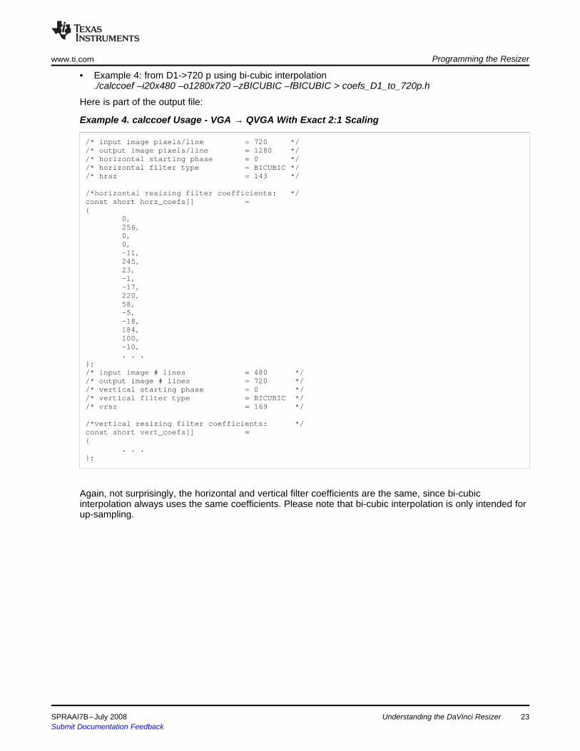
• Example 4: from D1->720 p using bi-cubic interpolation./calccoef –i20x480 –o1280x720 –zBICUBIC –fBICUBIC > coefs_D1_to_720p.h
Here is part of the output file:
Example 4. calccoef Usage - VGA → QVGA With Exact 2:1 Scaling
/* input image pixels/line = 720 *//* output image pixels/line = 1280 *//* horizontal starting phase = 0 *//* horizontal filter type = BICUBIC *//* hrsz = 143 */
/*horizontal resizing filter coefficients: */const short horz_coefs[] ={
0,256,0,0,-11,245,23,-1,-17,220,58,-5,-18,184,100,-10,. . .
};/* input image # lines = 480 *//* output image # lines = 720 *//* vertical starting phase = 0 *//* vertical filter type = BICUBIC *//* vrsz = 169 */
/*vertical resizing filter coefficients: */const short vert_coefs[] ={
. . .};
Again, not surprisingly, the horizontal and vertical filter coefficients are the same, since bi-cubicinterpolation always uses the same coefficients. Please note that bi-cubic interpolation is only intended forup-sampling.
SPRAAI7B–July 2008 Understanding the DaVinci Resizer 23Submit Documentation Feedback

4.4 Programming the Resizer RegistersProgramming the Resizer www.ti.com
The complete description of each register and field is not provided here. The focus is given instead todetails of certain aspects of the register configuration that are error prone and therefore requires specialattention.
The resizer register map is shown in Table 4.
Table 4. Resizer Register MapAddress Register Description
0x01C7:0C00 PID Peripheral revision and class information0x01C7:0C04 PCR Peripheral control register0x01C7:0C08 RSZ_CNT Resizer control bits0x01C7:0C0C OUT_SIZE Output width and height after resizing0x01C7:0C10 IN_START Input starting information0x01C7:0C10 IN_SIZE Input width and height before resizing0x01C7:0C18 SDR_INADD Input SDRAM address0x01C7:0C1C SDR_INOFF SDRAM offset for the input line0x01C7:0C20 SDR_OUTADD Output SDRAM address0x01C7:0C24 SDR_OUTOFF SDRAM offset for the output line0x01C7:0C28 HFILT10 Horizontal filter coefficients 1 and 00x01C7:0C2C HFILT32 Horizontal filter coefficients 3 and 20x01C7:0C30 HFILT54 Horizontal filter coefficients 5 and 40x01C7:0C34 HFILT76 Horizontal filter coefficients 7 and 60x01C7:0C38 HFILT98 Horizontal filter coefficients 9 and 80x01C7:0C3C HFILT1110 Horizontal filter coefficients 11 and 100x01C7:0C40 HFILT1312 Horizontal filter coefficients 13 and 120x01C7:0C44 HFILT1514 Horizontal filter coefficients 15 and 140x01C7:0C48 HFILT1716 Horizontal filter coefficients 17 and 160x01C7:0C4C HFILT1918 Horizontal filter coefficients 19 and 180x01C7:0C50 HFILT2120 Horizontal filter coefficients 21 and 200x01C7:0C54 HFILT2322 Horizontal filter coefficients 23 and 220x01C7:0C58 HFILT2524 Horizontal filter coefficients 25 and 240x01C7:0C5C HFILT2726 Horizontal filter coefficients 27 and 260x01C7:0C60 HFILT2928 Horizontal filter coefficients 29 and 280x01C7:0C64 HFILT3130 Horizontal filter coefficients 31 and 300x01C7:0C68 VFILT10 Vertical filter coefficients 1 and 00x01C7:0C6C VFILT32 Vertical filter coefficients 3 and 20x01C7:0C70 VFILT54 Vertical filter coefficients 5 and 40x01C7:0C74 VFILT76 Vertical filter coefficients 7 and 60x01C7:0C78 VFILT98 Vertical filter coefficients 9 and 80x01C7:0C7C VFILT1110 Vertical filter coefficients 11 and 100x01C7:0C80 VFILT1312 Vertical filter coefficients 13 and 120x01C7:0C84 VFILT1514 Vertical filter coefficients 15 and 140x01C7:0C88 VFILT1716 Vertical filter coefficients 17 and 160x01C7:0C8C VFILT1918 Vertical filter coefficients 19 and 180x01C7:0C90 VFILT2120 Vertical filter coefficients 21 and 200x01C7:0C94 VFILT2322 Vertical filter coefficients 23 and 220x01C7:0C98 VFILT2524 Vertical filter coefficients 25 and 240x01C7:0C9C VFILT2726 Vertical filter coefficients 27 and 260x01C7:0CA0 VFILT2928 Vertical filter coefficients 29 and 28
24 Understanding the DaVinci Resizer SPRAAI7B–July 2008Submit Documentation Feedback

4.4.1 PCR Register
4.4.2 RSZ_CNT Register
4.4.3 Memory Address and Offset Registers
4.4.4 VPSS PCR and SDR_REQ_EXP Registers
www.ti.com Programming the Resizer
Table 4. Resizer Register Map (continued)Address Register Description
0x01C7:0CA4 VFILT3130 Vertical filter coefficients 31 and 300x01C7:0CA8 YENH Luminance enhancer
The resizer can be configured to get data from either the Preview Engine/CCDC or from DDR memorydirectly. Regardless of the source, the resizer always works in one-shot mode, i.e., the processing mustbe enabled every time. As a result, the PCR.enable bit must be enabled for every frame.
The PCR.busy bit signals the completion of processing of current frame data. However, it does NOTindicate that all data is readily available in the output buffer. In fact, some of the data may still be in theresizer write buffer waiting to be written to DDR. Therefore, one cannot simply pull the PCR.busy bit todetermine whether the output data is ready. The only reliable indication for this purpose is the resizerinterrupt.
To ensure the quality of the output, the RSZ_CNT.cbilin bit needs to be configured depending on the valueof RSZ_CNT.hrsz. As discussed in Section 3.5, in case of up-sampling, this bit should be set to 1 toenable bi-linear interpolation for horizontal chroma data processing; in case of down-sampling, on theother hand, this bit should be set to 0 so that chroma is low-pass filtered with luma.
The RSZ_CNT.hrsz and RSZ_CNT.vrsz value MUST be set based on the input and output size accordingto the equations in Section 4.1. Correct settings are critical for the hardware to work properly.
The SDR_INADD and SDR_OUTADD specify the address of the input and output buffer in DDR memory.These addresses must be 32-byte aligned or the 5-LSBs are zeroed.
For image buffers that are not 32-bytes aligned, uses can use the IN_START_horz filed to indicate thecorrect starting point of processing. For example, if the buffer is at location 0x8700c00c. 0x8700c000 is tobe programmed into SDR_INADD, and IN_START.horz = (0xc>>1) if pixel size is 2 bytes/pixel, forY/Cb/Cr 4:2:2 input, or IN_START.horz=0xc for 8-bit planner input.
The SDR_INOFF and SDR_OUTOFF specify the bye offset of each line for the input and output imagebuffers, respectively. This line offset is commonly referred to as line pitch or stride for 2-D image buffers.Both SDR_INOFF and SDR_OUTOFF MUST be multiples of 32-byte and the 5-LSBs are zeroed.
The resizer hardware is designed in such a way that its operation is regulated by the input rate, withoutregard to the status of its write buffer. This is not a problem when the input is coming from the CCDC orpreviewer, when the data rate has already been regulated and restricted. However, when input data iscoming from DDR memory, the input data rate can be as high as 400 Mbytes/second, putting a hugepressure on the system DDR bandwidth. This also can cause overflow of its write buffer, where processeddata is temporarily stored before being written to DDR memory, especially for the case of up-scaling.
To alleviate this problem, the input rate must be reduced significantly. The SDR_REQ_EXP register isthere solely for this purpose.
SDR_REQ_EXP register can be used to insert delays between consecutive read requests from resizer,preview engine, and the histogram module. For resizer, the field is SDR_REQ_EXP.RESZ_EXP, and thevalue ranges from 0 – 0X3FF, where 0 is no delay and 0x3FF is maximum delay. The actual delay isSDR_REQ_EXP.RESZ_EXP*32 cycles. The maximum clock is 200 MHz if the device is running full-speedat 600 MHz.
SPRAAI7B–July 2008 Understanding the DaVinci Resizer 25Submit Documentation Feedback

5 The Resizer Driver
5.1 Overview of the Resizer Driver
Top Layer
OS centric. implements functions such as: open(), close(),
ioctl(), mmap(), init_module(), cleanup_mpdule(), etc.
Middle Layer
Transition layer between logic channel and actual hardware,
Bottom Layer
Hardware centric, handle the configuration of the actual
hardware
The Resizer Driver www.ti.com
When overflow occurs in the resizer write buffer memory, one or more of the fourVPSS_PCR.RSZx_WBL_O (x = 1,2,3,4) fields are set to indicate this condition. These fields can becleared by writing a 1 to them.
The resizer driver is a Linux character driver. It works for MontaVista® Linux 2.6.10 platform. The resizerdriver is a loadable module, which can be loaded/unloaded at run-time. The resizer gets its major numberfrom the kernel at run-time.
Here is a list of features that the resizer driver supports.• Y/CbCr 4:2:2 color interleaved data input• 8-bit planar or grayscale data input.• Input from DDRAM• Both application-allocated and resizer driver allocated buffers, as long as they are physically
contiguous, as required by hardware.• Multiple open/access
Here are the features that the driver does not support:• On-the-fly mode, which gets data from preview engine or CCDC directly.• Multi-passing operations for resizing ratio greater than 4x or less than x, or for output size greater than
1280 ( >x scaling) or 640 ( < x scaling). The multi-passing operations are supported at the applicationlevel. Please refer to application example on multi-passing.
The reizer driver has a multi-layer architecture to abstract the top layer from the actual resizer hardware.This is to support multiple application users opening multiple logical channels that use the same resizerhardware underneath.
Figure 28 shows the 3-layer architecture.
Figure 28. 3-Layer Architecture of the RSZ Module
Top layer: This layer handles all OS level driver API implementations and operations associated with logicchannel. This layer should be OS centric and hardware agnostic.
Bottom layer: This layer is responsible for the actual configuration of the resizer hardware through writingto the resizer MMRs. It should be OS agnostic and hardware centric.
Middle layer: This layer is mainly responsible for the transition between logic channel and physicalhardware. It also handles the ISR.
Understanding the DaVinci Resizer26 SPRAAI7B–July 2008Submit Documentation Feedback

5.2 The Resizer Driver APIwww.ti.com The Resizer Driver
At top level, the resizer driver implements the usual Linux driver APIs, namely open, close, mmap andioctl. It does not implement read and write, however, to avoid the need to implement memory copybetween user and kernel space.
Please refer to the documentation that is released with the product for a complete description of theresizer driver API.
All the resizer-specific APIs are defined in the davinci_resizer.h header file, including ioctls andparameters.
Here is the list of all resizer specific ioctls:• RSZ_REQBUF: request buffer(s) to be allocated by driver• RSZ_QUERYBUF: query the physical memory of driver allocated buffer• RSZ_S_PARAM: set resizer parameters for a logic channel• RSZ_G_PARAM: get resizer parameters for a logic channel• RSZ_RESIZE: perform the resizer operation• RSZ_G_STATUS: query the status of the resizer• RSZ_S_PRIORITY: set the priority of the logic channel• RSZ_S_PRIORITY: set the priority of the logic channel• RSZ_S_EXP: set the delays inserted between consecutive resizer reads from DDR
Here is the definition for the rsz_reqbufs structure passed as the parameter of the RSZ_REQBUFS ioctl.This provides information on the type of buffers, size of buffers and number of buffers to be allocatedtypedef struct rsz_reqbufs{
int buf_type; // buffer type: RSZ_BUF_IN/RSZ_BUF/OUTint size; // size of the buffer in bytesint count; // # of buffers to be allocated
}rsz_reqbufs_t;
Here is the definition of the resizer parameter structure used in the RSZ_S_PARAM and RSZ_G_PARAMioctls:typedef struct rsz_params{
int in_hsize; // input frame horizontal sizeint in_vsize; // input frame vertical sizeint in_pitch; // offset between two rows of input frameint inptyp; // for determining 16-bit or 8-bit dataint vert_starting_pixel; // for specifying vertical starting pixel in inputint horz_starting_pixel; // for specifying horizontal starting pixel in inputint cbilin; // # defined, filter with luma or bi-linear interpolationint pix_fmt; // # defined, UYVY or YUYVint out_hsize; // output frame horizontal sizeint out_vsize; // output frame vertical sizeint out_pitch; // offset between two rows of output frameint hstph; // for specifying horizontal starting phaseint vstph; // for specifying vertical starting phaseshort hfilt_coeffs[32]; // horizontal filter coefficientsshort vfilt_coeffs[32]; // vertical filter coefficientsrsz_yenh_t yenh_params; // luma edge enhancement parameters
}rsz_params_t;
SPRAAI7B–July 2008 Understanding the DaVinci Resizer 27Submit Documentation Feedback

6 Programming Examples
6.1 Resize Using Only One Field
Programming Examples www.ti.com
These parameters are closely mapped to the underneath resizer memory mapped registers.
Here is the definition of the rsz_buffer structure and the rsz_resize structure used in the RSZ_RESIZEioctl:typedef struct rsz_buffer{
int index; // input buffer descriptorint buf_type; // output buffer descriptorint offset; // physical address of bufferint size; // size of buffer
}rsz_buffer_t;
typedef struct rsz_resize{
rsz_buffer_t in_buf; // input buffer descriptorrsz_buffer_t out_buf; // output buffer descriptor
}rsz_resize_t;
The index field in the rsz_buffer structure indicates which buffer to use when it is allocated by the resizerdriver using the RSZ_REQBUFS ioctl. In this case, the offset field is ignored by the driver. If a buffer wasallocated outside of the resizer driver, for example, by the V4L2 capture driver, then this field should be -1and the offset field should be the physical address for the buffer.
Several examples are provided with this application report to illustrate the usage of the resizer driver.These examples run on the DM644x DVEVM.
This example shows how to resize using only one of the fields of the input. This scenario can typically befound in applications that do not implement an input de-interlacing module but need the input to beprogressive, for example, video conferencing or video phone. The typical target resolution is CIF(352×288) or QVGA (320×240).
The name of the example application is:
resize_one_field_fixed
Type:
resize_one_field_fixed –h displays the usage of this application:
Options:-s | --svideo Use s-video instead of composite video input-c | --count Number of frames to run the demo [-1(forever)]-r | --resolution Output resolution [720x480]-h | --help Print this message
The input resolution is fixed at 720×240, which uses only the top field of the input. The output resolutioncan be configured using the –r option. The default is 720×480. When an output resolution other than720×480 is selected, the output picture is centered on the display. The –s option selects the s-video inputconnector, rather than the default composite input connector.
Usage example:
resize_one_field_fixed –s –r 352x288
This converts the input to CIF resolution. The input is from the s-video connector.
Source code for this example is in the resize_one_field_fixed.c file. The coefficients are pre-calculated andstored in the coefs.h file.
Understanding the DaVinci Resizer28 SPRAAI7B–July 2008Submit Documentation Feedback
6.2 Continuous Zoom-In and Zoom-Out Example
6.3 Pass-Through Example
7 References
www.ti.com References
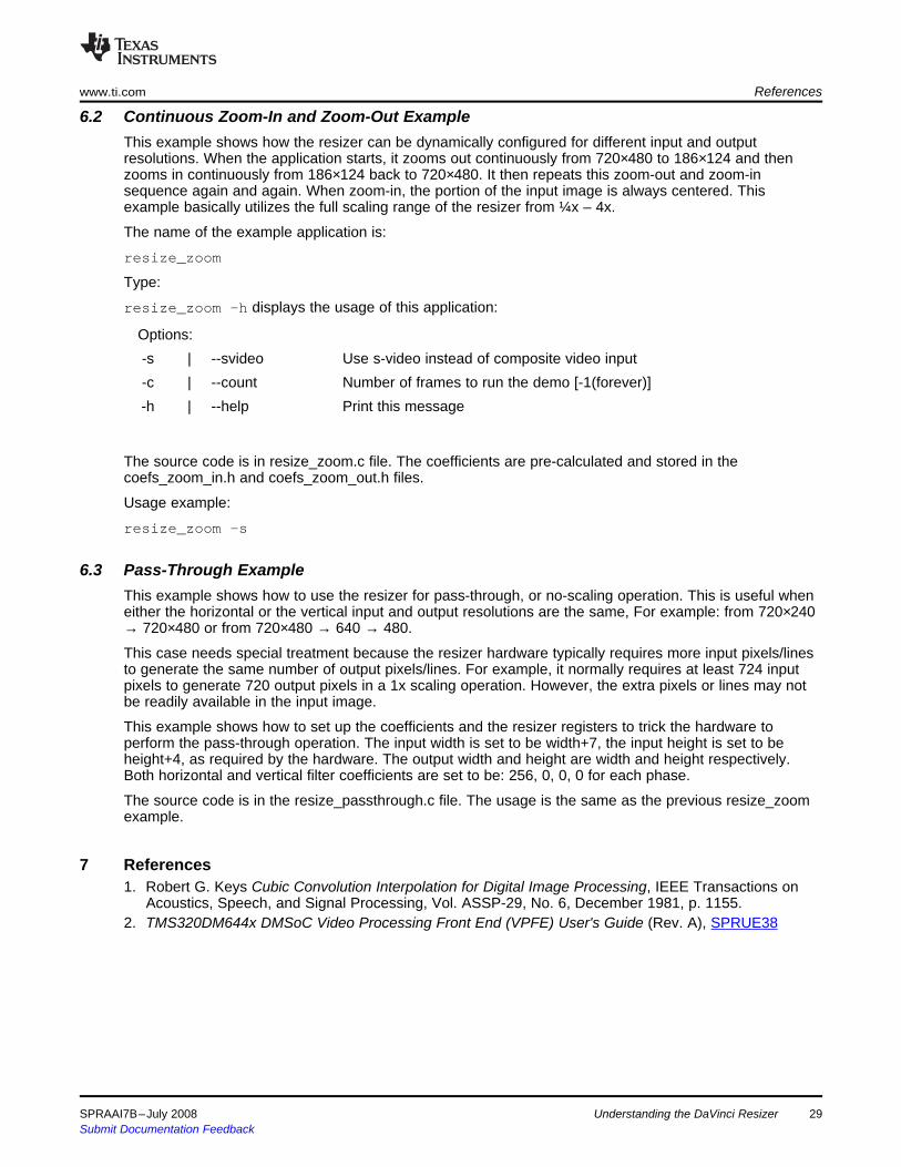
This example shows how the resizer can be dynamically configured for different input and outputresolutions. When the application starts, it zooms out continuously from 720×480 to 186×124 and thenzooms in continuously from 186×124 back to 720×480. It then repeats this zoom-out and zoom-insequence again and again. When zoom-in, the portion of the input image is always centered. Thisexample basically utilizes the full scaling range of the resizer from ¼x – 4x.
The name of the example application is:
resize_zoom
Type:
resize_zoom –h displays the usage of this application:
Options:-s | --svideo Use s-video instead of composite video input-c | --count Number of frames to run the demo [-1(forever)]-h | --help Print this message
The source code is in resize_zoom.c file. The coefficients are pre-calculated and stored in thecoefs_zoom_in.h and coefs_zoom_out.h files.
Usage example:
resize_zoom -s
This example shows how to use the resizer for pass-through, or no-scaling operation. This is useful wheneither the horizontal or the vertical input and output resolutions are the same, For example: from 720×240→ 720×480 or from 720×480 → 640 → 480.
This case needs special treatment because the resizer hardware typically requires more input pixels/linesto generate the same number of output pixels/lines. For example, it normally requires at least 724 inputpixels to generate 720 output pixels in a 1x scaling operation. However, the extra pixels or lines may notbe readily available in the input image.
This example shows how to set up the coefficients and the resizer registers to trick the hardware toperform the pass-through operation. The input width is set to be width+7, the input height is set to beheight+4, as required by the hardware. The output width and height are width and height respectively.Both horizontal and vertical filter coefficients are set to be: 256, 0, 0, 0 for each phase.
The source code is in the resize_passthrough.c file. The usage is the same as the previous resize_zoomexample.
1. Robert G. Keys Cubic Convolution Interpolation for Digital Image Processing, IEEE Transactions onAcoustics, Speech, and Signal Processing, Vol. ASSP-29, No. 6, December 1981, p. 1155.
2. TMS320DM644x DMSoC Video Processing Front End (VPFE) User's Guide (Rev. A), SPRUE38
SPRAAI7B–July 2008 Understanding the DaVinci Resizer 29Submit Documentation Feedback

IMPORTANT NOTICETexas Instruments Incorporated and its subsidiaries (TI) reserve the right to make corrections, modifications, enhancements, improvements,and other changes to its products and services at any time and to discontinue any product or service without notice. Customers shouldobtain the latest relevant information before placing orders and should verify that such information is current and complete. All products aresold subject to TI’s terms and conditions of sale supplied at the time of order acknowledgment.TI warrants performance of its hardware products to the specifications applicable at the time of sale in accordance with TI’s standardwarranty. Testing and other quality control techniques are used to the extent TI deems necessary to support this warranty. Except wheremandated by government requirements, testing of all parameters of each product is not necessarily performed.TI assumes no liability for applications assistance or customer product design. Customers are responsible for their products andapplications using TI components. To minimize the risks associated with customer products and applications, customers should provideadequate design and operating safeguards.TI does not warrant or represent that any license, either express or implied, is granted under any TI patent right, copyright, mask work right,or other TI intellectual property right relating to any combination, machine, or process in which TI products or services are used. Informationpublished by TI regarding third-party products or services does not constitute a license from TI to use such products or services or awarranty or endorsement thereof. Use of such information may require a license from a third party under the patents or other intellectualproperty of the third party, or a license from TI under the patents or other intellectual property of TI.Reproduction of TI information in TI data books or data sheets is permissible only if reproduction is without alteration and is accompaniedby all associated warranties, conditions, limitations, and notices. Reproduction of this information with alteration is an unfair and deceptivebusiness practice. TI is not responsible or liable for such altered documentation. Information of third parties may be subject to additionalrestrictions.Resale of TI products or services with statements different from or beyond the parameters stated by TI for that product or service voids allexpress and any implied warranties for the associated TI product or service and is an unfair and deceptive business practice. TI is notresponsible or liable for any such statements.TI products are not authorized for use in safety-critical applications (such as life support) where a failure of the TI product would reasonablybe expected to cause severe personal injury or death, unless officers of the parties have executed an agreement specifically governingsuch use. Buyers represent that they have all necessary expertise in the safety and regulatory ramifications of their applications, andacknowledge and agree that they are solely responsible for all legal, regulatory and safety-related requirements concerning their productsand any use of TI products in such safety-critical applications, notwithstanding any applications-related information or support that may beprovided by TI. Further, Buyers must fully indemnify TI and its representatives against any damages arising out of the use of TI products insuch safety-critical applications.TI products are neither designed nor intended for use in military/aerospace applications or environments unless the TI products arespecifically designated by TI as military-grade or "enhanced plastic." Only products designated by TI as military-grade meet militaryspecifications. Buyers acknowledge and agree that any such use of TI products which TI has not designated as military-grade is solely atthe Buyer's risk, and that they are solely responsible for compliance with all legal and regulatory requirements in connection with such use.TI products are neither designed nor intended for use in automotive applications or environments unless the specific TI products aredesignated by TI as compliant with ISO/TS 16949 requirements. Buyers acknowledge and agree that, if they use any non-designatedproducts in automotive applications, TI will not be responsible for any failure to meet such requirements.Following are URLs where you can obtain information on other Texas Instruments products and application solutions:Products ApplicationsAmplifiers amplifier.ti.com Audio www.ti.com/audioData Converters dataconverter.ti.com Automotive www.ti.com/automotiveDSP dsp.ti.com Broadband www.ti.com/broadbandClocks and Timers www.ti.com/clocks Digital Control www.ti.com/digitalcontrolInterface interface.ti.com Medical www.ti.com/medicalLogic logic.ti.com Military www.ti.com/militaryPower Mgmt power.ti.com Optical Networking www.ti.com/opticalnetworkMicrocontrollers microcontroller.ti.com Security www.ti.com/securityRFID www.ti-rfid.com Telephony www.ti.com/telephonyRF/IF and ZigBee® Solutions www.ti.com/lprf Video & Imaging www.ti.com/video
Wireless www.ti.com/wireless
Mailing Address: Texas Instruments, Post Office Box 655303, Dallas, Texas 75265Copyright © 2008, Texas Instruments Incorporated