Embed Size (px)
Citation preview
Understanding the benefits of using a digital valve controller
Mark Buzzell
Business Manager, Metso Flow Control
© Metso
Evolution of Valve Positioners
2
Digital
(First Generation)
Analog
(Electro-pneumatic
/ Pneumatic)
Digital
(Next Generation)
© Metso
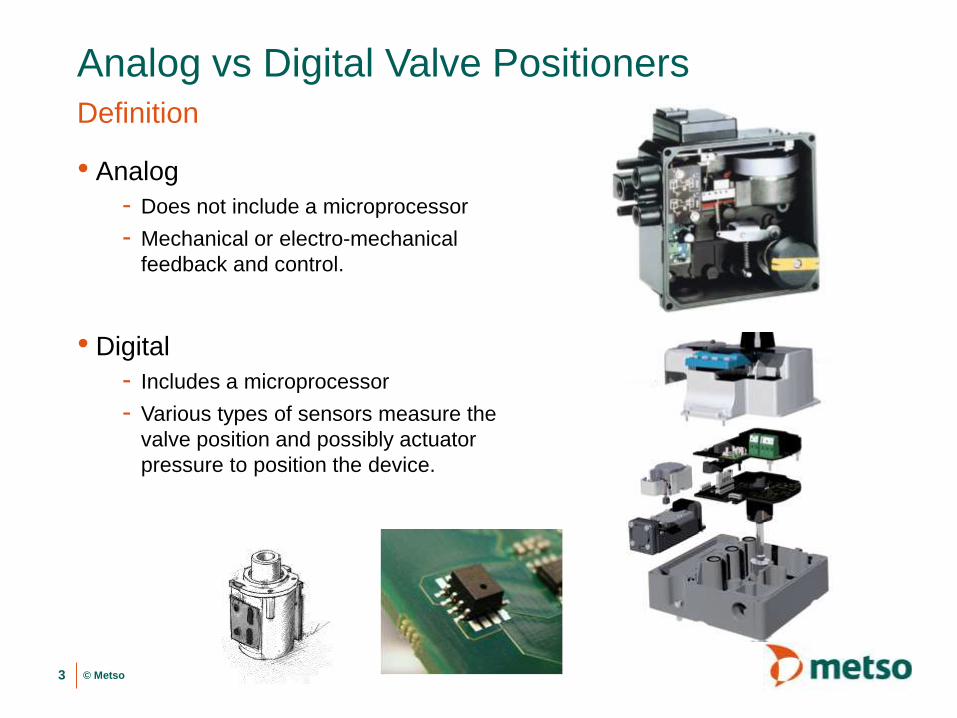
Analog vs Digital Valve PositionersDefinition
• Analog
- Does not include a microprocessor
- Mechanical or electro-mechanical
feedback and control.
• Digital
- Includes a microprocessor
- Various types of sensors measure the
valve position and possibly actuator
pressure to position the device.
3
Configuration / CalibrationAnalog vs Digital Positioners
4

© Metso
Analog PositionersConfiguration
• Mechanical configuration of the device…
- Cam moved to a defined position, side, or even replaced/modified
- Potential adjustment of spring positions

© Metso
Analog PositionersCalibration
• Zero (i.e. close) and Span (i.e. open) are manually adjusted during
calibration. These positions often affect each other requiring you to
go back and forth adjusting each one multiple times.
• Verifying performance is difficult and ideally requires the use of an
external test system to measure the position and test it’s response.

© Metso
First Generation Digital PositionersConfiguration / Calibration
• Either required the use of an expensive external configuration device
or if a basic user interface was included it often required a complex
user manual to use properly.
• Calibration often required manual PID tuning
7

© Metso
Next Generation Digital PositionersConfiguration / Calibration
• Large local user interface with capacitive buttons
• Guided startup wizard greatly simplifies
configuration and calibration.
• Calibration and tuning are fully automated
8

Wear & Vibration ToleranceAnalog vs Digital Positioners
9

© Metso
Analog PositionersWear / Vibration
• Mechanical feedback parts can wear or seize over time
• Physical connection to the actuator (especially with linear
applications) can wear over time.

© Metso
First Generation Digital PositionersWear / Vibration
• Typically used a contacting position sensor which would wear / break
over time.
• Physical connection to the actuator (especially with linear
applications) can wear over time.
11

© Metso
Next Generation Digital PositionersWear / Vibration
• Fully Contactless valve position sensing, eliminates any shaft or
sensor that could wear over time.
12

Control Advantages
13

© Metso
Proportional only control:
Beams, levers, springs, cam.
Analog Positioners

© Metso
Proportional only control:
The positioner will not correct for any offset after the initial
movement

© Metso
Advanced control
algorithm:
Based on detailed
mathematical study of
control valve dynamics.
Smart Digital Positioner

© Metso
Velocity
Fri
cti
on
Static friction
Dynamic friction
Actuator pressure
Control signal
Valve position
Accurate Valve ControlNonlinearities due to friction

© Metso
Without advanced control algorithm
With advanced control algorithm
Advanced Control Algorithm
Advanced control algorithm corrects for frictional effects:
• Algorithm learns static friction levels
• Pressure “boost” breaks static friction quickly
• Continually updated during operation
Reduces dead time and overall response time

© Metso
3.3 psi
101 gpm
Digital Positioner
9.7 psi
214 gpm
Analog Positioner
Black liquor make up, continuous digester
Advanced Control AlgorithmReduced process variability

Installed Flow Characteristics
20

© Metso
Valve & Process Characteristic
Relative valve travel, h
Rela
tive f
low
co
eff
icie
nt,
Q
Equal Percent (Typical Valve)
Quick Opening (Typical Process)
Linear
Linear:A flow characteristic in which the valve relative
opening directly correlates to the percentage flow,
e.g. a 50 % open valve gives 50% of maximum
flow, with a constant pressure drop across the
valve.
Quick Opening:
A flow characteristic in which a flow close to a
maximum flow is reached with a very small valve
opening.
Equal Percent:
Equal increments in the valve opening cause a
constant percentage increase in flow with a
constant pressure drop across the valve.

© Metso
40%
1.0
2.0
3.0
4.0
Installed Characteristic and Gain
Travel
Flo
w
40%
10%
• Describes the control behavior of a valve when it is operating in the process.
• Installed characteristics is an important indication of controllability.
Large changes in
valve position
produce small
changes in flow
Small changes in valve
position cause large
changes in flow
10%
22
Installed Characteristic Installed Gain
50%
50%
0.25
Equal changes in
valve position
produce equal
changes in flow
Ideal - easy to
tune and control

© Metso
Linearization of Installed characteristicsPositioner capabilities
• Proper valve selection for the
application is critical but of course
no valve has a perfectly linear
installed flow characteristic.
• The positioner can compensate for
this non-linearity by adjusting how
much the position changes versus
the set point.
• Analog positioners can do this with
a custom cam which is engineered
for the specific application/valve.
• Digital positioners can do this by
programming a signal modification
curve based on the valve sizing.

Diagnostics
© Metso
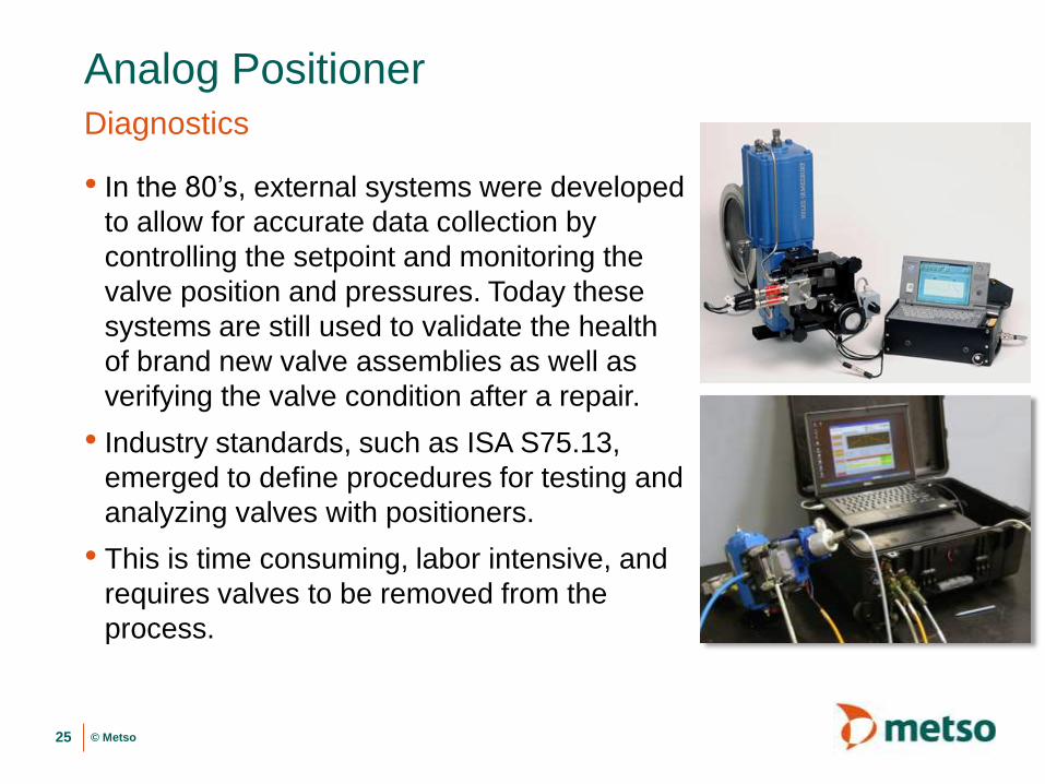
Analog PositionerDiagnostics
• In the 80’s, external systems were developed
to allow for accurate data collection by
controlling the setpoint and monitoring the
valve position and pressures. Today these
systems are still used to validate the health
of brand new valve assemblies as well as
verifying the valve condition after a repair.
• Industry standards, such as ISA S75.13,
emerged to define procedures for testing and
analyzing valves with positioners.
• This is time consuming, labor intensive, and
requires valves to be removed from the
process.
25

© Metso
First Generation Digital PositionersDiagnostics
• The Offline tests (such as the valve
signature) that were previously conducted
using external devices, were embedded
into digital valve controllers to eliminate
the need for these external systems.
• Many manufacturers provide these
diagnostics. Results must be available
from when the valve is new to use for
comparison and often require specialized
expertise to interpret.
26
Travel (deg)
Ac
tua
tor
Pre
ss
ure
Time (s)T
rave
l (
%)
© Metso
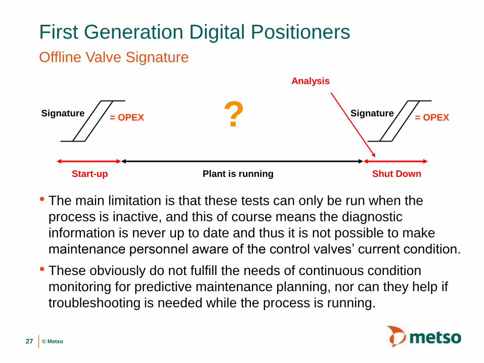
First Generation Digital PositionersOffline Valve Signature
• The main limitation is that these tests can only be run when the
process is inactive, and this of course means the diagnostic
information is never up to date and thus it is not possible to make
maintenance personnel aware of the control valves’ current condition.
• These obviously do not fulfill the needs of continuous condition
monitoring for predictive maintenance planning, nor can they help if
troubleshooting is needed while the process is running.
27
Plant is runningStart-up Shut Down
Analysis
Signature Signature?= OPEX = OPEX

© Metso
Next Generation Digital PositionersOnline Valve Diagnostics
• The second generation of valve
diagnostics included run time data for
the valve assembly. State of the art
valve controllers enabled sufficient run
time diagnostics data to support a
predictive maintenance strategy.
• This data included, up to 20, runtime
measurements of factors such as valve
assembly friction and deviations.
• Trending of historical data over the life
time of the valve assembly is helpful
for determining how possible problems
have developed, and how they may
develop into the future.
28
Steady State Deviation %

© Metso
Next Generation Digital PositionersSimplifying Diagnostics Analysis
• There is now a focus on helping operators
quickly determine the status of valve
assemblies with a clear summary of the
valve assembly’s health, without requiring
in-depth training on valve diagnostics.
• Graphical displays are used to simplify the
users experience and give them all of the
key information they need on a single page
- A summary of the health of the valve assembly
components, i.e. valve, actuator and positioner, as
well as control performance and the environment.
- Key measurement values such as the supply and
actuator pressure difference is displayed, as well
as the target versus valve position
- Recommended Actions provide clarity to make
correct maintenance decisions with little time/effort
29
Recommended
Actions
Description of Diagnostic

© Metso
Data analysis
Time
30
• No extra work during start-up or shut down
• No extra costs for diagnostics features
• Know your valve condition in the past, present and in the future. Correct focus for the shut down maintenance
− Valve performance is assessed during run-time
− Smart devices measure and store the diagnostic data by itself
− Best possible resolution and accuracy of information
From Offline Signatures to Online Diagnostics
Plant is runningStart-up
Shut down Plant is running

© Metso
Smart Positioners Diagnostic Types
• Smart Positioners have varying capabilities:
- Smart Positioners with Embedded vs. system based analysis
• With Embedded diagnostics the positioner stores all of the key information
into its own memory so the asset management system simply needs to
display it.
• System based diagnostics require a full asset management system which
polls the devices for data and the system performs analysis on the data.
- Smart positioners without pressure sensors
• Deviation and time based diagnostics
• No pressure knowledge so changes in valve friction cannot be accurately
measured. Other issues like supply pressure cannot be detected.
- Smart Positioners with pressure sensors
• Deviation, time based, and pressure (friction) based diagnostics.
31
© Metso
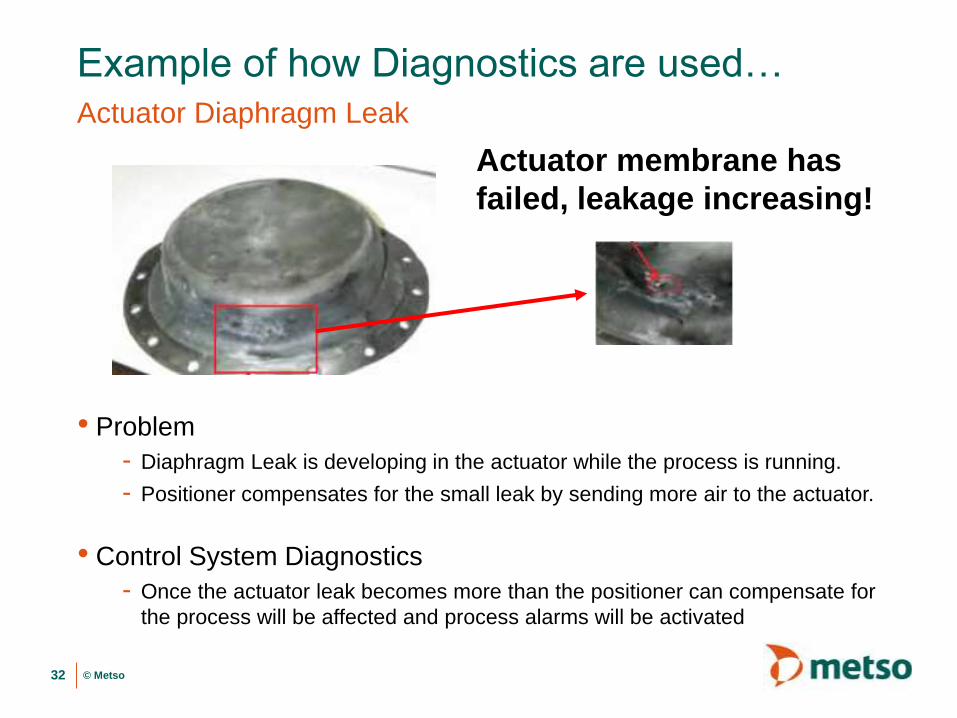
Example of how Diagnostics are used…Actuator Diaphragm Leak
• Problem
- Diaphragm Leak is developing in the actuator while the process is running.
- Positioner compensates for the small leak by sending more air to the actuator.
• Control System Diagnostics
- Once the actuator leak becomes more than the positioner can compensate for
the process will be affected and process alarms will be activated
32
Actuator membrane has
failed, leakage increasing!

© Metso
Example of how Diagnostics are used…Actuator Diaphragm Leak
• Different smart positioner diagnostic levels:
- 1st Generation Offline Testing
• Once actuator leak becomes more than the positioner can compensate for a
deviation alarm will be activated since it can no longer follow the set point.
- 2nd Generation Online Diagnostics
• Trending clearly shows the change in pneumatics output to compensate for
the leak. Some knowledge is required to know what this diagnostic means
and what actions need to be taken.
33

© Metso
Example of how Diagnostics are used…Actuator Diaphragm Leak
• Different smart positioner diagnostic levels continued:
- 3rd Generation Simplified Online Diagnostics
• Diagnostics are broken down into key indexes and clearly show a problem
developing with the actuator. A clear description is given describing the
problem and recommended actions.
34

© Metso
SummaryAdvantages / Disadvantages
• Analog Positioner Advantages over Digital
- Easy to understand / simple design.
- Lower initial purchase price
• Digital Positioner Advantages over Analog
- Simplified calibration
- Improved valve response / accuracy
- Ability to linearize installed flow characteristics
- Lower total cost of ownership due to faster startup, ease of diagnosing problems,
lower air consumption…
- Can notify of problems with the positioner, environment (i.e. supply pressure /
temperature), and the valve/actuator (friction / air leaks)
- Can collect historical data over the life of the valve for predictive maintenance
35
Thank You
Questions, Comments
36