Embed Size (px)
Citation preview
metals fabrication
UNDERSTANDING THE
BASICS
Edited by
F.C. Campbell
ASM International® Materials Park, Ohio 44073-0002
www.asminternational.org
Copyright © 2013 by
ASM International® All rights reserved
No part of this book may be reproduced, stored in a retrieval system, or transmitted, in any form or by any means, electronic, mechanical, photocopying, recording, or otherwise, without the written permission of the copyright owner.
First printing, November 2013
Great care is taken in the compilation and production of this book, but it should be made clear that NO WARRANTIES, EXPRESS OR IMPLIED, INCLUDING, WITHOUT LIMITA-TION, WARRANTIES OF MERCHANTABILITY OR FITNESS FOR A PARTICULAR PURPOSE, ARE GIVEN IN CONNECTION WITH THIS PUBLICATION. Although this information is believed to be accurate by ASM, ASM cannot guarantee that favorable results will be obtained from the use of this publication alone. This publication is intended for use by persons having technical skill, at their sole discretion and risk. Since the conditions of product or material use are outside of ASM’s control, ASM assumes no liability or obligation in connection with any use of this information. No claim of any kind, whether as to products or information in this publication, and whether or not based on negligence, shall be greater in amount than the purchase price of this product or publication in respect of which damages are claimed. THE REMEDY HEREBY PROVIDED SHALL BE THE EXCLUSIVE AND SOLE REMEDY OF BUYER, AND IN NO EVENT SHALL EITHER PARTY BE LIABLE FOR SPECIAL, INDIRECT OR CONSEQUENTIAL DAMAGES WHETHER OR NOT CAUSED BY OR RESULTING FROM THE NEGLIGENCE OF SUCH PARTY. As with any material, evaluation of the material under end-use conditions prior to specification is essential. Therefore, specific testing under actual conditions is recommended.
Nothing contained in this book shall be construed as a grant of any right of manufacture, sale, use, or reproduction, in connection with any method, process, apparatus, product, composi-tion, or system, whether or not covered by letters patent, copyright, or trademark, and nothing contained in this book shall be construed as a defense against any alleged infringement of letters patent, copyright, or trademark, or as a defense against liability for such infringement.
Comments, criticisms, and suggestions are invited, and should be forwarded to ASM International.
Prepared under the direction of the ASM International Technical Book Committee (2012–2013), Bradley J. Diak, Chair.
ASM International staff who worked on this project include Scott Henry, Senior Manager, Content Development and Publishing; Karen Marken, Senior Managing Editor; Steven Lampman, Content Developer; Sue Sellers, Editorial Assistant; Madrid Tramble, Manager of Production; and Diane Whitelaw, Production Coordinator.
Library of Congress Control Number 2013952505
ISBN-13: 978-1-62708-018-7 ISBN-10: 1-62708-018-X
SAN: 204-7586
ASM International® Materials Park, OH 44073-0002
www.asminternational.org
Printed in the United States of America
Dedicated to the memory ofF.C. (Flake) Campbell
Flake Campbell passed away shortly after completing his work on this volume. His 38-year career at The Boeing Co. was split equally between engineering and manufacturing. He worked in the engineering laboratories, manufacturing R&D, engineering on four production aircraft programs, and in production opera-tions. He was a 2001 recipient of Boeing’s Senior Technical Fellow award for accomplishments in his field. At retirement, Campbell was a director and senior technical fellow in the field of manufacturing technology within Boeing’s Phan-tom Works service. Campbell received an M.B.A. from Maryville University in St. Louis, 1994, and an M.S. in metallurgical engineering, from the University of Missouri at Rolla, 1972.
Flake loved metallurgical engineering, a lifelong vocation that culminated in the authorship and publication of numerous educational and reference books. He wrote or edited ten books including these ASM International titles: Elements of Metallurgy and Engineering Alloys, 2008; Structural Composite Materials, 2010; Joining—Understanding the Basics, 2011; Phase Diagrams—Understanding the Basics, 2011; Lightweight Materials—Understanding the Basics, 2012; Fatigue and Fracture—Understanding the Basics, 2012; Inspection of Metals—Under-standing the Basics (2013). Metals Fabrication—Understanding the Basics was the final book he authored before his death in 2013.
Copyright © 2013 ASM International®
All rights reservedwww.asminternational.org
Metals Fabrication—Understanding the BasicsF.C. Campbell, editor
Preface
This book deals with the fabrication processes used to produce metallic products. It is intended primarily for technical personnel who want to learn more about metallic fabrication processes. This book is useful to designers, structural engineers, materials and process engineers, manufacturing engi-neers, technicians, production personnel, management, faculty, and students.
The first chapter gives an introduction to the processes used at the mill to produce metals and their alloys. Procedures for the primary melting, casting, and hot rolling of steel, aluminum, and titanium are covered. The importance of ladle metallurgy and secondary melting operations, such as vacuum induction melting, vacuum arc remelting, electroslag remelt-ing, and stainless steel refining by argon oxidation decarburization, are emphasized. Both ingot casting and continuous casting are included. Roll-ing methods covered include hot and cold rolling, along with annealing procedures (batch and continuous).
The second chapter on casting discusses the basics of solidification, casting imperfections, and the important casting methods—sand casting, plaster and shell casting, evaporative pattern casting, investment casting, permanent mold casting, cold and hot chamber die casting, squeeze cast-ing, semisolid metal processing, and centrifugal casting.
The third chapter is on the bulk deformation processes—forging, extrusion, and drawing. The differences between hot and cold working are initially covered. This is followed by a discussion of forging includ-ing hammers and presses, die design and materials, lubrication, forging defects, and forging processes. Forging process descriptions are given for open-die forging, closed-die impression forging, hot upset forging, roll forging, high-energy-rate forging, ring rolling, radial forging, isothermal and hot-die forging, precision forging, and cold forging. The chapter con-cludes with cold and hot extrusion and the various drawing operations.
Sheet metal forming processes (fourth chapter) usually employ hot or cold rolled sheet or strip material that is formed into a desired shape. Top-ics covered include cutting of plate and flat sheet, die materials for forming,

x / Preface
forming lubricants, and the forming processes of blanking, piercing, fine-edge blanking and piercing, press bending and press-brake forming, deep drawing, stretch forming, spinning, rubber-pad forming, fluid-cell forming, drop hammer forming, electromagnetic forming, and superplastic forming.
The fifth chapter covers traditional, abrasive, and nontraditional machin-ing processes with an emphasis on conventional machining. Topics include workpiece machinability, dimensional and surface finish requirements, surface integrity, the mechanics of chip formation, tool wear and cutting tool materials, cutting and grinding fluids, machining equipment, machin-ing parameters, and machining forces and power requirements.
The sixth chapter discusses the various heat treatments used to thermally alter the property of the metal. Included are steel heat treatments—annealing, stress relieving, normalizing, spheroidizing, and hardening by quenching and tempering. Direct and interrupted quenching processes are explained. The second section of the chapter discusses the various surface-hardening processes, such as flame hardening, induction hardening, case hardening by carburization, nitriding, and carbonitriding. The third part of the chapter covers precipitation hardening with an emphasis of alumi-num alloys. However, precipitation hardening is also used extensively to strengthen magnesium alloys, nickel-base superalloys, beryllium-copper alloys, and precipitation-hardening (PH) stainless steels.
The seventh chapter covers the rather wide topic of surface finishing and coatings. Areas included are cleaning methods, abrasive finishing, polishing and buffing, eletropolishing, mass finishing methods such as barrel and vibratory finishing, phosphate and chromate conversion coat-ings, electroplating (e.g., copper plating, chromium plating, and cadmium plating), electroless plating, weld overlay coatings, thermal spray coatings, high-temperature ceramic coatings, and chemical vapor deposition (CVD) and physical vapor deposition (PVD).
Powder metallurgy (eighth chapter) is the process of blending fine pow-dered materials, pressing them into a desired shape or form (compacting), and then heating the compressed material in a controlled atmosphere to bond the material together (sintering). The powder metallurgy process generally consists of four basic steps: powder manufacture, powder blend-ing, compacting, and sintering. Compacting is generally performed at room temperature, and the elevated-temperature process of sintering is usually conducted at atmospheric pressure. Full-density processes are also included. Optional secondary processing is often used to obtain special properties or enhanced precision.
I would like to acknowledge the help and guidance of Karen Marken, ASM International, and the staff at ASM for their valuable contributions.
F.C. Campbell St. Louis, Missouri
October 2012

Copyright © 2013 ASM International®
All rights reservedwww.asminternational.org
Metals Fabrication—Understanding the BasicsF.C. Campbell, editor
contents
Preface ix
chaPter 1Primary mill fabrication 1
Ironmaking . . . . . . . . . . . . . . . . . . . . . . . . . . . . 1Steelmaking . . . . . . . . . . . . . . . . . . . . . . . . . . . . 4Alloy Steel Refining . . . . . . . . . . . . . . . . . . . . . . . . 8Stainless Steel Refining . . . . . . . . . . . . . . . . . . . . . . 16Ingot Casting . . . . . . . . . . . . . . . . . . . . . . . . . . . 19Continuous Casting . . . . . . . . . . . . . . . . . . . . . . . . 21Rolling. . . . . . . . . . . . . . . . . . . . . . . . . . . . . . . 22Aluminum Production . . . . . . . . . . . . . . . . . . . . . . . 37Titanium Production. . . . . . . . . . . . . . . . . . . . . . . . 42
chaPter 2casting 47
Casting Alloys . . . . . . . . . . . . . . . . . . . . . . . . . . . 49Solidification. . . . . . . . . . . . . . . . . . . . . . . . . . . . 49Casting Defects . . . . . . . . . . . . . . . . . . . . . . . . . . 56Gating and Risering . . . . . . . . . . . . . . . . . . . . . . . . 61Melting Methods. . . . . . . . . . . . . . . . . . . . . . . . . . 63Casting Methods. . . . . . . . . . . . . . . . . . . . . . . . . . 71
chaPter 3bulk Deformation 103
Hot Working . . . . . . . . . . . . . . . . . . . . . . . . . . . . 104Cold Working . . . . . . . . . . . . . . . . . . . . . . . . . . . 107Forging . . . . . . . . . . . . . . . . . . . . . . . . . . . . . . 109Hammers and Presses . . . . . . . . . . . . . . . . . . . . . . . 110Die Design and Materials . . . . . . . . . . . . . . . . . . . . . 113
vi / contents
Die Steels . . . . . . . . . . . . . . . . . . . . . . . . . . . . . 116Friction and Lubrication in Forging . . . . . . . . . . . . . . . . 117Forging Imperfections . . . . . . . . . . . . . . . . . . . . . . . 119Forging Processes . . . . . . . . . . . . . . . . . . . . . . . . . 122Open-Die Forging . . . . . . . . . . . . . . . . . . . . . . . . . 122Closed-Die Forging . . . . . . . . . . . . . . . . . . . . . . . . 124Hot Upset Forging . . . . . . . . . . . . . . . . . . . . . . . . . 130Roll Forging . . . . . . . . . . . . . . . . . . . . . . . . . . . . 132High-Energy-Rate Forging . . . . . . . . . . . . . . . . . . . . 134Ring Rolling . . . . . . . . . . . . . . . . . . . . . . . . . . . . 137Rotary Swaging of Bars and Tubes . . . . . . . . . . . . . . . . 138Radial Forging. . . . . . . . . . . . . . . . . . . . . . . . . . . 140Rotary Forging . . . . . . . . . . . . . . . . . . . . . . . . . . 141Isothermal and Hot-Die Forging. . . . . . . . . . . . . . . . . . 144Precision Forging . . . . . . . . . . . . . . . . . . . . . . . . . 146Cold Forging. . . . . . . . . . . . . . . . . . . . . . . . . . . . 148Cold Extrusion. . . . . . . . . . . . . . . . . . . . . . . . . . . 151Hot Extrusion . . . . . . . . . . . . . . . . . . . . . . . . . . . 154Drawing . . . . . . . . . . . . . . . . . . . . . . . . . . . . . . 157
chaPter 4forming 163
Preparation of Plate and Flat Sheet . . . . . . . . . . . . . . . . 163Forming . . . . . . . . . . . . . . . . . . . . . . . . . . . . . . 169Die Materials for Sheet Metal Forming . . . . . . . . . . . . . . 170Selection and Use of Lubricants in Forming Sheet Metal . . . . . 173Blanking . . . . . . . . . . . . . . . . . . . . . . . . . . . . . . 176Piercing . . . . . . . . . . . . . . . . . . . . . . . . . . . . . . 178Fine-Edge Blanking and Piercing . . . . . . . . . . . . . . . . . 178Bending and Springback. . . . . . . . . . . . . . . . . . . . . . 180Defects in Sheet Metal Parts . . . . . . . . . . . . . . . . . . . 181Press Bending . . . . . . . . . . . . . . . . . . . . . . . . . . . 183Press-Brake Forming . . . . . . . . . . . . . . . . . . . . . . . 186Deep Drawing . . . . . . . . . . . . . . . . . . . . . . . . . . . 189Fundamentals of Drawing . . . . . . . . . . . . . . . . . . . . . 190Stretch Forming . . . . . . . . . . . . . . . . . . . . . . . . . . 194Spinning . . . . . . . . . . . . . . . . . . . . . . . . . . . . . . 196Rubber-Pad Forming . . . . . . . . . . . . . . . . . . . . . . . 199Fluid-Cell Process . . . . . . . . . . . . . . . . . . . . . . . . . 201Fluid Forming . . . . . . . . . . . . . . . . . . . . . . . . . . . 202Drop Hammer Forming . . . . . . . . . . . . . . . . . . . . . . 203Electromagnetic Forming (EMF) . . . . . . . . . . . . . . . . . 204Superplastic Forming (SPF) . . . . . . . . . . . . . . . . . . . . 206
contents / vii
chaPter 5machining 213
Types of Machining Processes . . . . . . . . . . . . . . . . . . 213Types of Machining Equipment . . . . . . . . . . . . . . . . . . 215Workpiece Machinability . . . . . . . . . . . . . . . . . . . . . 215Dimensional and Surface Finish Tolerances. . . . . . . . . . . . 217Surface Integrity. . . . . . . . . . . . . . . . . . . . . . . . . . 217The Mechanics of Chip Formation . . . . . . . . . . . . . . . . 222Tool Wear in Metal Cutting . . . . . . . . . . . . . . . . . . . . 225Cutting Tool Materials. . . . . . . . . . . . . . . . . . . . . . . 229Application/Grade Selection. . . . . . . . . . . . . . . . . . . . 235Cutting Fluids . . . . . . . . . . . . . . . . . . . . . . . . . . . 237Basic Chip Producing Processes and Equipment . . . . . . . . . 241Machining Parameters. . . . . . . . . . . . . . . . . . . . . . . 250Forces and Power . . . . . . . . . . . . . . . . . . . . . . . . . 254Grinding . . . . . . . . . . . . . . . . . . . . . . . . . . . . . . 257Grinding Wheels . . . . . . . . . . . . . . . . . . . . . . . . . 258Nontraditional Machining Processes . . . . . . . . . . . . . . . 261
chaPter 6heat treatment 271
The Iron-Carbon System . . . . . . . . . . . . . . . . . . . . . 272Annealing . . . . . . . . . . . . . . . . . . . . . . . . . . . . . 276Normalizing . . . . . . . . . . . . . . . . . . . . . . . . . . . . 277Spheroidizing . . . . . . . . . . . . . . . . . . . . . . . . . . . 277Quench Hardening. . . . . . . . . . . . . . . . . . . . . . . . . 278Continuous Cooling Transformation Diagrams . . . . . . . . . . 279Austenitizing . . . . . . . . . . . . . . . . . . . . . . . . . . . 281Quenching . . . . . . . . . . . . . . . . . . . . . . . . . . . . . 283Hardenability . . . . . . . . . . . . . . . . . . . . . . . . . . . 286Tempering . . . . . . . . . . . . . . . . . . . . . . . . . . . . . 288Interrupted Quenching. . . . . . . . . . . . . . . . . . . . . . . 291Temper Embrittlement . . . . . . . . . . . . . . . . . . . . . . . 295Surface Hardening of Steel . . . . . . . . . . . . . . . . . . . . 297Flame Hardening . . . . . . . . . . . . . . . . . . . . . . . . . 298Induction Hardening. . . . . . . . . . . . . . . . . . . . . . . . 299Case Hardening . . . . . . . . . . . . . . . . . . . . . . . . . . 300Carburizing . . . . . . . . . . . . . . . . . . . . . . . . . . . . 301Nitriding . . . . . . . . . . . . . . . . . . . . . . . . . . . . . . 310Carbonitriding . . . . . . . . . . . . . . . . . . . . . . . . . . . 313Precipitation Hardening . . . . . . . . . . . . . . . . . . . . . . 314Precipitation Hardening of Aluminum Alloys. . . . . . . . . . . 317
viii / contents
chaPter 7finishing and coating 325
Environmental Regulations . . . . . . . . . . . . . . . . . . . . 325Cleaning . . . . . . . . . . . . . . . . . . . . . . . . . . . . . . 326Abrasive Finishing Methods. . . . . . . . . . . . . . . . . . . . 330Polishing and Buffing . . . . . . . . . . . . . . . . . . . . . . . 331Lapping . . . . . . . . . . . . . . . . . . . . . . . . . . . . . . 334Electropolishing . . . . . . . . . . . . . . . . . . . . . . . . . . 335Mass Finishing . . . . . . . . . . . . . . . . . . . . . . . . . . 335Rust-Preventive Compounds. . . . . . . . . . . . . . . . . . . . 338Phosphate Conversion Coatings . . . . . . . . . . . . . . . . . . 338Chromate Conversion Coatings . . . . . . . . . . . . . . . . . . 339Electroplating Processes . . . . . . . . . . . . . . . . . . . . . . 339Selective Plating Processes . . . . . . . . . . . . . . . . . . . . 343Electroless Plating Processes . . . . . . . . . . . . . . . . . . . 344Hot Dip Coating of Steels . . . . . . . . . . . . . . . . . . . . . 346Babbitting . . . . . . . . . . . . . . . . . . . . . . . . . . . . . 348Weld-Overlay Coatings . . . . . . . . . . . . . . . . . . . . . . 349Thermal Spray Coatings . . . . . . . . . . . . . . . . . . . . . . 350Porcelain Enameling. . . . . . . . . . . . . . . . . . . . . . . . 353Ceramic Coatings . . . . . . . . . . . . . . . . . . . . . . . . . 353Pack Cementation . . . . . . . . . . . . . . . . . . . . . . . . . 355Chemical Vapor Deposition . . . . . . . . . . . . . . . . . . . . 357Physical Vapor Deposition. . . . . . . . . . . . . . . . . . . . . 360Ion Implantation . . . . . . . . . . . . . . . . . . . . . . . . . . 365Painting . . . . . . . . . . . . . . . . . . . . . . . . . . . . . . 365
chaPter 8Powder metallurgy 373
Powder Characteristics . . . . . . . . . . . . . . . . . . . . . . 374Powder Production Processes . . . . . . . . . . . . . . . . . . . 380Powder Treatments . . . . . . . . . . . . . . . . . . . . . . . . 388Powder Consolidation . . . . . . . . . . . . . . . . . . . . . . . 393Powder Metallurgy Part Defects. . . . . . . . . . . . . . . . . . 406Secondary Operations . . . . . . . . . . . . . . . . . . . . . . . 408
index 413
Copyright © 2013 ASM International®
All rights reservedwww.asminternational.org
Metals Fabrication—Understanding the BasicsF.C. Campbell, editor
Chapter 1Primary Mill Fabrication
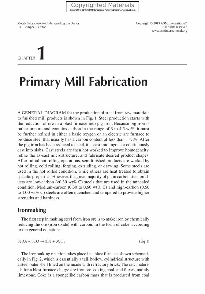
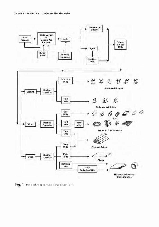
A generAl diAgrAm for the production of steel from raw materials to finished mill products is shown in Fig. 1. Steel production starts with the reduction of ore in a blast furnace into pig iron. Because pig iron is rather impure and contains carbon in the range of 3 to 4.5 wt%, it must be further refined in either a basic oxygen or an electric arc furnace to produce steel that usually has a carbon content of less than 1 wt%. After the pig iron has been reduced to steel, it is cast into ingots or continuously cast into slabs. Cast steels are then hot worked to improve homogeneity, refine the as-cast microstructure, and fabricate desired product shapes. After initial hot rolling operations, semifinished products are worked by hot rolling, cold rolling, forging, extruding, or drawing. Some steels are used in the hot rolled condition, while others are heat treated to obtain specific properties. However, the great majority of plain carbon steel prod-ucts are low-carbon (<0.30 wt% C) steels that are used in the annealed condition. Medium-carbon (0.30 to 0.60 wt% C) and high-carbon (0.60 to 1.00 wt% C) steels are often quenched and tempered to provide higher strengths and hardness.
Ironmaking
The first step in making steel from iron ore is to make iron by chemically reducing the ore (iron oxide) with carbon, in the form of coke, according to the general equation:
Fe2O3 + 3CO Æ 2Fe + 3CO2 (Eq 1)
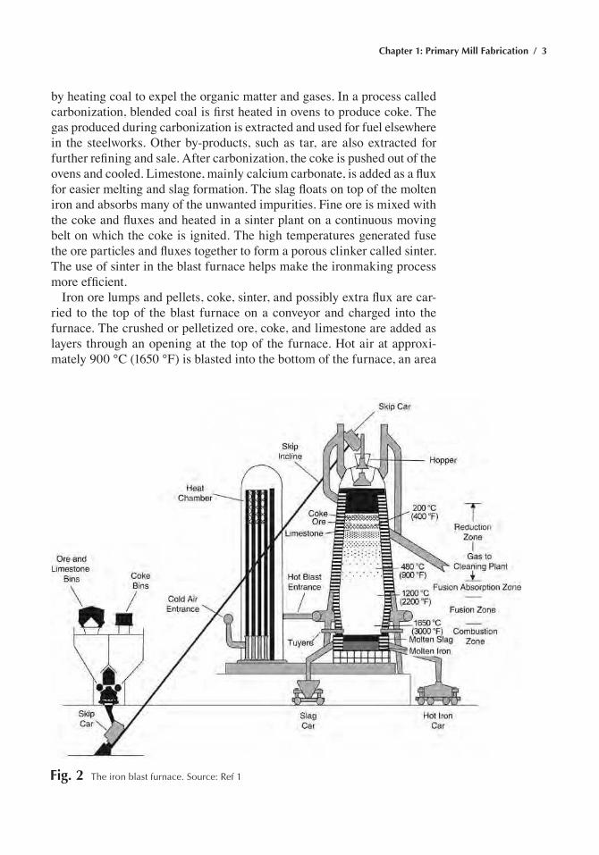
The ironmaking reaction takes place in a blast furnace, shown schemati-cally in Fig. 2, which is essentially a tall, hollow, cylindrical structure with a steel outer shell lined on the inside with refractory brick. The raw materi-als for a blast furnace charge are iron ore, coking coal, and fluxes, mainly limestone. Coke is a spongelike carbon mass that is produced from coal
2 / Metals Fabrication—Understanding the Basics
Fig. 1 principal steps in steelmaking. Source: ref 1
Chapter 1: Primary Mill Fabrication / 3
by heating coal to expel the organic matter and gases. In a process called carbonization, blended coal is first heated in ovens to produce coke. The gas produced during carbonization is extracted and used for fuel elsewhere in the steelworks. Other by-products, such as tar, are also extracted for further refining and sale. After carbonization, the coke is pushed out of the ovens and cooled. Limestone, mainly calcium carbonate, is added as a flux for easier melting and slag formation. The slag floats on top of the molten iron and absorbs many of the unwanted impurities. Fine ore is mixed with the coke and fluxes and heated in a sinter plant on a continuous moving belt on which the coke is ignited. The high temperatures generated fuse the ore particles and fluxes together to form a porous clinker called sinter. The use of sinter in the blast furnace helps make the ironmaking process more efficient.
Iron ore lumps and pellets, coke, sinter, and possibly extra flux are car-ried to the top of the blast furnace on a conveyor and charged into the furnace. The crushed or pelletized ore, coke, and limestone are added as layers through an opening at the top of the furnace. Hot air at approxi-mately 900 °C (1650 °F) is blasted into the bottom of the furnace, an area
Fig. 2 the iron blast furnace. Source: ref 1
4 / Metals Fabrication—Understanding the Basics
called the bosh, through water-cooled copper nozzles called tuyeres. The oxygen in the air reacts with the coke to form carbon monoxide gas accord-ing to Eq 1 and, at the same time, generates a great deal of heat.
Frequently, oil or coal is injected with the air, which allows less expen-sive coke to be used. The carbon monoxide gas flows up through the blast furnace, removing oxygen from the iron ore and leaving iron. The iron in the ore reduces to metallic iron from iron because the free energies of CO and CO2 are both lower than that of iron oxide. This greatly increases the temperature and provides the required carbon for steelmaking.
The resulting liquid iron is tapped at regular intervals by opening a hole in the bottom of the furnace, and the hot metal flows into specially constructed railway containers that transport the liquid iron to the basic oxygen furnace (BOF), where it is made into steel. The molten slag, which floats on the iron, is removed by tapping at regular intervals. A successful steelmaking furnace campaign can last for ten continuous years or more. If the furnace were allowed to cool, damage to the refractory lining bricks could result from their contraction as they cooled. Eventually, the refrac-tory brick linings are eroded away, the steelmaking campaign is stopped, and the furnace is relined with new bricks.
Steelmaking
The two dominant steelmaking methods during the 20th century were the Bessemer and open-hearth processes. In the Bessemer process, devel-oped in 1856, air was blown through molten pig iron to reduce the carbon and silicon contents to tolerable levels. In the open-hearth processes, devel-oped shortly after in 1858, steel was made in a very large, shallow furnace in which carbon reduction was achieved by an oxidizing slag. Although the open-hearth furnace required a longer time (8 h versus 30 min for the Bessemer process), it was more widely used because much larger amounts of steel could be produced. Both of these processes are now obsolete, and the basic oxygen furnace (BOF) has largely replaced both of these older processes.
Basic Oxygen Furnace (BOF)
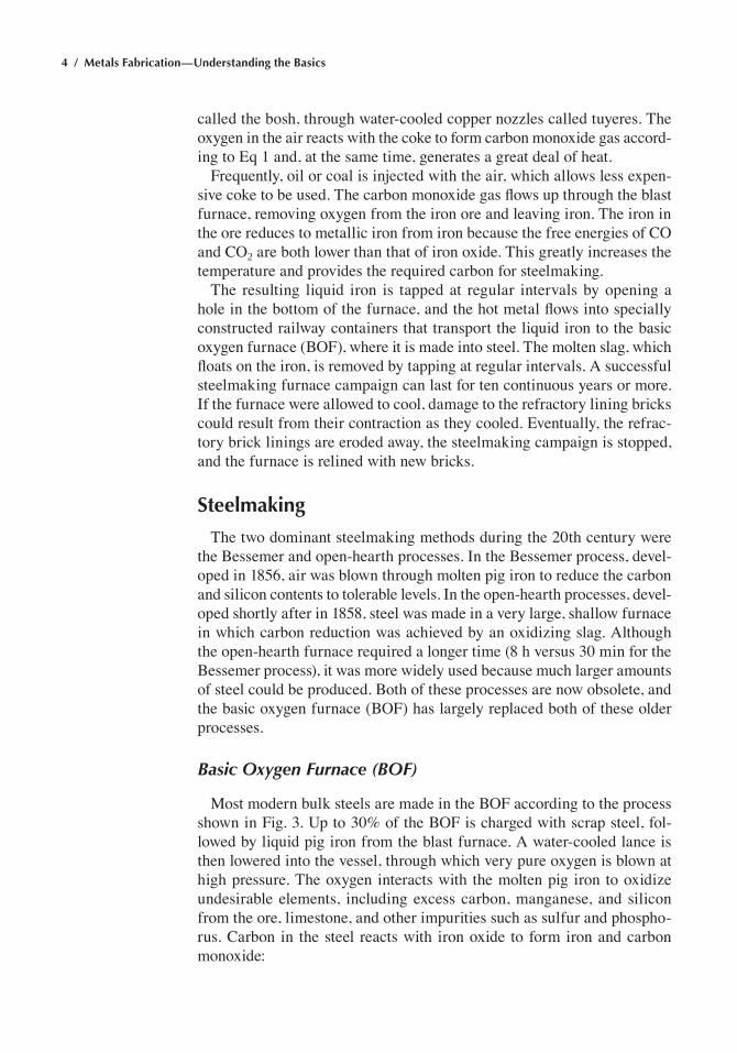
Most modern bulk steels are made in the BOF according to the process shown in Fig. 3. Up to 30% of the BOF is charged with scrap steel, fol-lowed by liquid pig iron from the blast furnace. A water-cooled lance is then lowered into the vessel, through which very pure oxygen is blown at high pressure. The oxygen interacts with the molten pig iron to oxidize undesirable elements, including excess carbon, manganese, and silicon from the ore, limestone, and other impurities such as sulfur and phospho-rus. Carbon in the steel reacts with iron oxide to form iron and carbon monoxide:
Chapter 1: Primary Mill Fabrication / 5
FeO + C Æ Fe + CO (Eq 2)
A careful balance between the relative amounts of pig iron and scrap charged into the converter is maintained as a means of controlling the tem-perature and to ensure that steel of the required specification is produced. After a sample has been taken to verify the chemical composition of the steel, the vessel is tilted to allow the molten steel to flow out. The steel is tapped into a ladle where further composition adjustments are made. Dur-ing tapping, small quantities of other metals and fluxes are often added to control the state of oxidation and to meet requirements for particular grades of steel. Finally, the vessel is turned upside down to remove the remaining slag. A modern BOF vessel can make up to 318,000 kg (700,000 lb) of steel in approximately 40 min with the desired carbon content and a low level of impurities such as sulfur and phosphorus.
While in the ladle, certain alloying elements can be added to the steel to control the state of oxidation and produce the desired chemical com-
Fig. 3 Basic oxygen furnace. Source: ref 2
6 / Metals Fabrication—Understanding the Basics
position. The ladle furnace is maintained at a specified temperature by external heat from electrodes in the lid that covers the ladle. After the desired chemical composition is achieved, the ladle can be placed in a vacuum chamber to remove undesirable gases such as hydrogen and oxy-gen. Degassing is used for higher-quality steel products, such as railroad rail, sheet, plate, bar, and forged products.
Electric Arc Furnace (EAF)
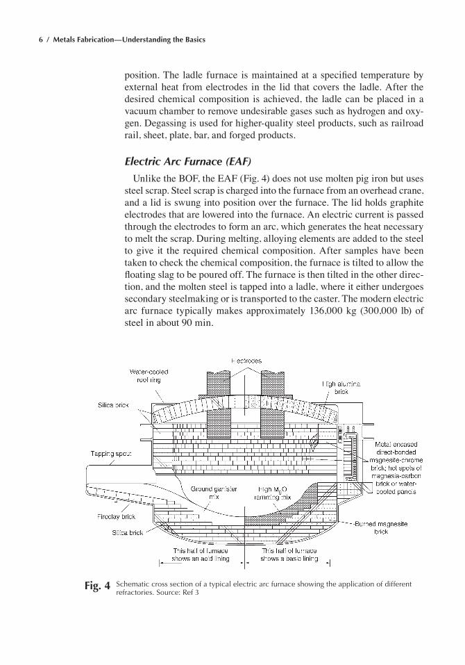
Unlike the BOF, the EAF (Fig. 4) does not use molten pig iron but uses steel scrap. Steel scrap is charged into the furnace from an overhead crane, and a lid is swung into position over the furnace. The lid holds graphite electrodes that are lowered into the furnace. An electric current is passed through the electrodes to form an arc, which generates the heat necessary to melt the scrap. During melting, alloying elements are added to the steel to give it the required chemical composition. After samples have been taken to check the chemical composition, the furnace is tilted to allow the floating slag to be poured off. The furnace is then tilted in the other direc-tion, and the molten steel is tapped into a ladle, where it either undergoes secondary steelmaking or is transported to the caster. The modern electric arc furnace typically makes approximately 136,000 kg (300,000 lb) of steel in about 90 min.
Fig. 4 Schematic cross section of a typical electric arc furnace showing the application of different refractories. Source: ref 3
Chapter 1: Primary Mill Fabrication / 7
Because the EAF has a relatively low capital equipment cost and uses steel scrap, this process is used where local supplies of steel scrap are avail-able (almost everywhere) and has given rise to what are known as “mini” mills. The EAF is used for producing alloy steels that contain appreciable amounts of easily oxidized alloying elements, such as chromium, tungsten, and molybdenum. It can also be used to make steels requiring very low sulfur and phosphorus contents. Special slags are used to lower the sulfur and phosphorus levels and to protect against oxidation of alloying ele-ments. An additional benefit is that temperature control with the electric arc process is very good.
Ladle Metallurgy
The demand for higher-quality and cleaner steels has led to refining operations after the steel is made by either the basic oxygen or electric arc processes. These refining processes are conducted in the liquid steel transfer ladle into which the steel has been poured after the basic oxygen or electric arc processes are complete. By conducting these refining processes outside the steelmaking furnace, valuable steelmaking resources are freed up. In addition, reducing atmospheres are more easily applied for desul-furization. Vacuum degassing is also possible with the steel in a ladle, and argon lances can be used to stir the steel to make the composition more homogeneous. Vacuum degassing produces ultralow-carbon steels, with carbon contents as low as 0.002 wt%. This allows these ultralow-carbon steels to be continuously annealed and have the high formability required for deep-drawing applications. Vacuum degassing also removes hydrogen that can result in hydrogen flaking and porosity.
Residual Elements and Cleanliness
Various manufacturing practices can affect the oxygen, nitrogen, and sulfur contents and hence the cleanliness of the product. Cleanliness usu-ally refers to the nonsteel phases, such as oxides, sulfides, and silicates that can be present in steel. The smaller the amount of these phases, the cleaner the steel. They are present in the form of inclusions that can have significant undesirable effects on the properties of steel. Tin, antimony, arsenic, and copper are considered residual or tramp elements in steel, although copper can be added as an alloying element to improve the corrosion resistance of some steels. Tramp elements remain in steel because they are difficult to remove during steelmaking and refining. Steels made by electric furnace melting employing scrap as a raw material contain higher levels of residual elements than steels made in an integrated steelmaking facility using the blast furnace-BOF route. Some electric furnace melting shops use direct reduced-iron pellets to dilute the effect of these residuals.
8 / Metals Fabrication—Understanding the Basics
Hydrogen is also a residual element that can be very deleterious. Hydro-gen is soluble in liquid steel and somewhat soluble in austenite. However, it is insoluble in ferrite and is rejected as atomic hydrogen (H+). If trapped inside the steel, usually in products such as thick plate, heavy forgings, or railroad rail, hydrogen will accumulate on the surfaces of manganese sul-fide inclusions. Eventually, enough molecular hydrogen (H2) accumulates and sufficient pressure develops to create internal cracks. As the cracks grow, they form what are termed hydrogen flakes, and the product must be scrapped. However, if the product is slow cooled from the rolling tempera-ture, atomic hydrogen has sufficient time to diffuse out of the product, thus avoiding hydrogen damage. Vacuum degassing is used to remove hydrogen from liquid steel.
There have been major advances in the production of steel during the last 30 years, and continuous casting, in which great attention is being paid to the cleanliness of the steel, has become the dominant production method. Vacuum deoxidization is also being used to eliminate oxygen, and the steel is protected by argon atmospheres in covered tundishes that yield cleaner steel with a lower inclusion content. This is beneficial to the mechanical properties and uniformity of the final product. Continuous casting also produces a product that is much closer to a shape that is amenable to hot rolling.
More and more steel sheet is now being produced by minimills. These mills, employing electric arc furnaces, continuously cast steel into slabs several inches thick and a few feet wide. The slab is immediately fed through a long furnace to the hot rolling mill. However, because steel scrap is the primary raw material, controlling the residual elements in the composition can be problematic. Copper is particularly troublesome because it is not easily removed from liquid steel, and, as its concentration increases, it can produce cracks due to hot shortness by penetrating the grain boundaries and causing grain-boundary cracking during hot rolling. Hot shortness is the tendency for alloys to separate along grain boundar-ies when stressed or deformed at temperatures near the melting point. Hot shortness is caused by a low-melting constituent, often present only in minute amounts, that has segregated to the grain boundaries.
Alloy Steel Refining
High-strength steels are available in a variety of quality levels, depend-ing on the type of melting practice used. While many of these steels were originally air melted, the trend has been to move to more advanced melt-ing techniques such as vacuum degassing, electroslag remelting (ESR), vacuum arc remelting (VAR), and double vacuum melting (vacuum induction melting followed by vacuum arc remelting, or VIM-VAR) for improved cleanliness and higher quality. Since the mid-1970s, improve-ments in melting process control and inspection have steadily increased
Chapter 1: Primary Mill Fabrication / 9
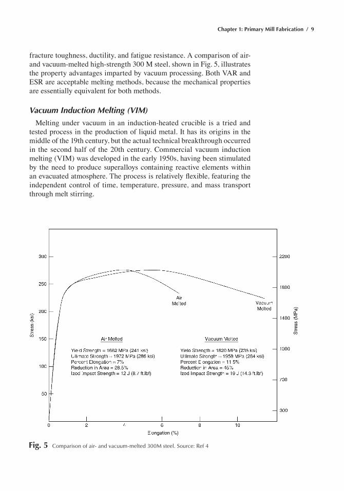
fracture toughness, ductility, and fatigue resistance. A comparison of air- and vacuum-melted high-strength 300 M steel, shown in Fig. 5, illustrates the property advantages imparted by vacuum processing. Both VAR and ESR are acceptable melting methods, because the mechanical properties are essentially equivalent for both methods.
Vacuum Induction Melting (VIM)
Melting under vacuum in an induction-heated crucible is a tried and tested process in the production of liquid metal. It has its origins in the middle of the 19th century, but the actual technical breakthrough occurred in the second half of the 20th century. Commercial vacuum induction melting (VIM) was developed in the early 1950s, having been stimulated by the need to produce superalloys containing reactive elements within an evacuated atmosphere. The process is relatively flexible, featuring the independent control of time, temperature, pressure, and mass transport through melt stirring.
Fig. 5 Comparison of air- and vacuum-melted 300M steel. Source: ref 4
10 / Metals Fabrication—Understanding the Basics
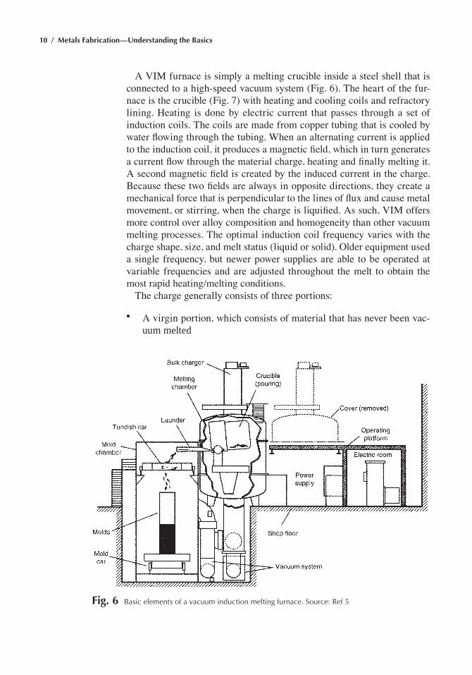
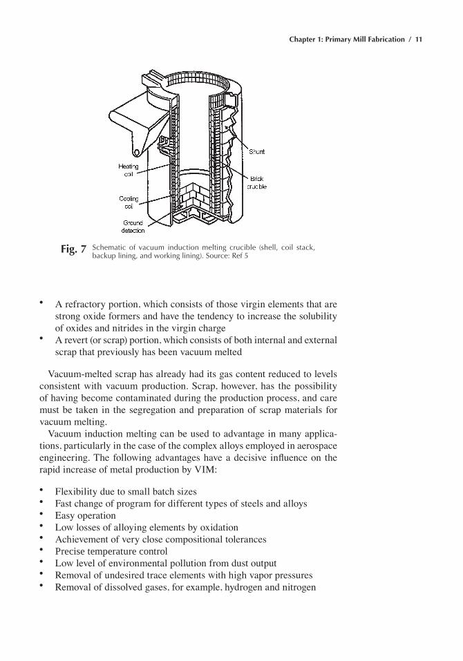
A VIM furnace is simply a melting crucible inside a steel shell that is connected to a high-speed vacuum system (Fig. 6). The heart of the fur-nace is the crucible (Fig. 7) with heating and cooling coils and refractory lining. Heating is done by electric current that passes through a set of induction coils. The coils are made from copper tubing that is cooled by water flowing through the tubing. When an alternating current is applied to the induction coil, it produces a magnetic field, which in turn generates a current flow through the material charge, heating and finally melting it. A second magnetic field is created by the induced current in the charge. Because these two fields are always in opposite directions, they create a mechanical force that is perpendicular to the lines of flux and cause metal movement, or stirring, when the charge is liquified. As such, VIM offers more control over alloy composition and homogeneity than other vacuum melting processes. The optimal induction coil frequency varies with the charge shape, size, and melt status (liquid or solid). Older equipment used a single frequency, but newer power supplies are able to be operated at variable frequencies and are adjusted throughout the melt to obtain the most rapid heating/melting conditions.
The charge generally consists of three portions:
• A virgin portion, which consists of material that has never been vac-uum melted
Fig. 6 Basic elements of a vacuum induction melting furnace. Source: ref 5
Chapter 1: Primary Mill Fabrication / 11
• A refractory portion, which consists of those virgin elements that are strong oxide formers and have the tendency to increase the solubility of oxides and nitrides in the virgin charge
• A revert (or scrap) portion, which consists of both internal and external scrap that previously has been vacuum melted
Vacuum-melted scrap has already had its gas content reduced to levels consistent with vacuum production. Scrap, however, has the possibility of having become contaminated during the production process, and care must be taken in the segregation and preparation of scrap materials for vacuum melting.
Vacuum induction melting can be used to advantage in many applica-tions, particularly in the case of the complex alloys employed in aerospace engineering. The following advantages have a decisive influence on the rapid increase of metal production by VIM:
• Flexibility due to small batch sizes• Fast change of program for different types of steels and alloys• Easy operation• Low losses of alloying elements by oxidation• Achievement of very close compositional tolerances• Precise temperature control• Low level of environmental pollution from dust output• Removal of undesired trace elements with high vapor pressures• Removal of dissolved gases, for example, hydrogen and nitrogen
Fig. 7 Schematic of vacuum induction melting crucible (shell, coil stack, backup lining, and working lining). Source: ref 5
12 / Metals Fabrication—Understanding the Basics
Vacuum induction melting is indispensable in the manufacture of superalloys. Compared to air-melting processes such electric arc furnaces with argon oxygen decarburization (AOD) converters, VIM of superal-loys provides a considerable reduction in oxygen and nitrogen contents. Accordingly, with fewer oxides and nitrides formed, the microcleanliness of vacuum-melted superalloys is greatly improved compared to air EAF/AOD-melted superalloys. Additionally, high-vapor-pressure elements (spe-cifically lead and bismuth) that may enter the scrap during the manufacture of superalloy components are reduced during the melting process. There-fore, compared to EAF/AOD-melted alloys, VIM-melted superalloys have improved fatigue and stress-rupture properties.
Control of alloying elements with VIM can also achieve much tighter levels than in EAF/AOD products. However, problems can arise in the case of alloying elements with high vapor pressures, such as manganese. Vacuum melting is also more costly than EAF/AOD melting. The EAF/AOD process allows compositional modification (reduction of carbon, titanium, sulfur, silicon, aluminum, etc.). In vacuum melting, the charge remains very close in composition to the nominal chemistry of the initial furnace charge. Minor reductions in carbon content may occur, and most VIM operations now include a deliberate desulfurization step. However, the composition is substantially fixed by choice of the initial charge mate-rials, and these materials are inevitably higher-priced than those that are used in EAF/AOD.
Vacuum Arc Remelting (VAR) and Electroslag Remelting (ESR)
Two commonly used remelting processes for metal refinement are electro-slag remelting (ESR) and vacuum arc remelting (VAR). In both processes, an electrode is melted as it advances into the melting region of the furnace. As the working face of the electrode is heated to the melting point, drops of liquid metal that fall from the electrode face are collected in a lower crucible and rapidly solidified. However, ESR and VAR have very differ-ent melting methods, which have implications regarding the magnitude of cooling rates obtained and the nature of defects created by the remelting process itself. The VAR process is carried out in a vacuum, while the ESR process typically occurs under atmospheric conditions—although electro-slag remelting under vacuum (VACESR), or under pressure, is a process variation of ESR.
The VAR process is used to improve the cleanliness and refine the structure of standard air-melted or vacuum-induction-melted (VIM) ingots—typically referred to as consumable electrodes for remelting. The VAR process is also commonly used in the triplex production (VIM-ESR-VAR) of superalloys. The VAR process was the first commercial remelting process for superalloys. It was used in the late 1950s to manufacture mate-
Chapter 1: Primary Mill Fabrication / 13
rials for the aircraft industry. Current applications of VAR processing include the production of steels and superalloys as well as the melting of reactive metals such as titanium and zirconium alloys. The melt cleanli-ness and homogeneity from VAR provides benefits in both primary ingot and foundry shape casting for high-integrity applications where improved fatigue and fracture toughness of the final product are essential. This includes aerospace applications, high-strength steels, ball bearing steels, die steels, tool steels (cold and hot work steels), power generation, defense, and medical and nuclear industries.
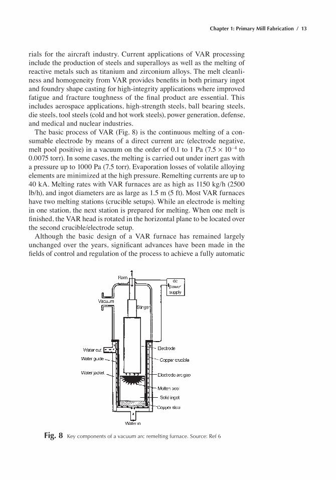
The basic process of VAR (Fig. 8) is the continuous melting of a con-sumable electrode by means of a direct current arc (electrode negative, melt pool positive) in a vacuum on the order of 0.1 to 1 Pa (7.5 ¥ 10–4 to 0.0075 torr). In some cases, the melting is carried out under inert gas with a pressure up to 1000 Pa (7.5 torr). Evaporation losses of volatile alloying elements are minimized at the high pressure. Remelting currents are up to 40 kA. Melting rates with VAR furnaces are as high as 1150 kg/h (2500 lb/h), and ingot diameters are as large as 1.5 m (5 ft). Most VAR furnaces have two melting stations (crucible setups). While an electrode is melting in one station, the next station is prepared for melting. When one melt is finished, the VAR head is rotated in the horizontal plane to be located over the second crucible/electrode setup.
Although the basic design of a VAR furnace has remained largely unchanged over the years, significant advances have been made in the fields of control and regulation of the process to achieve a fully automatic
Fig. 8 Key components of a vacuum arc remelting furnace. Source: ref 6
14 / Metals Fabrication—Understanding the Basics
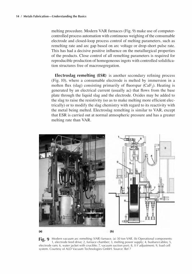
melting procedure. Modern VAR furnaces (Fig. 9) make use of computer-controlled process automation with continuous weighing of the consumable electrode and closed-loop process control of melting parameters, such as remelting rate and arc gap based on arc voltage or drop-short pulse rate. This has had a decisive positive influence on the metallurgical properties of the products. Close control of all remelting parameters is required for reproducible production of homogeneous ingots with controlled solidifica-tion structures free of macrosegregation.
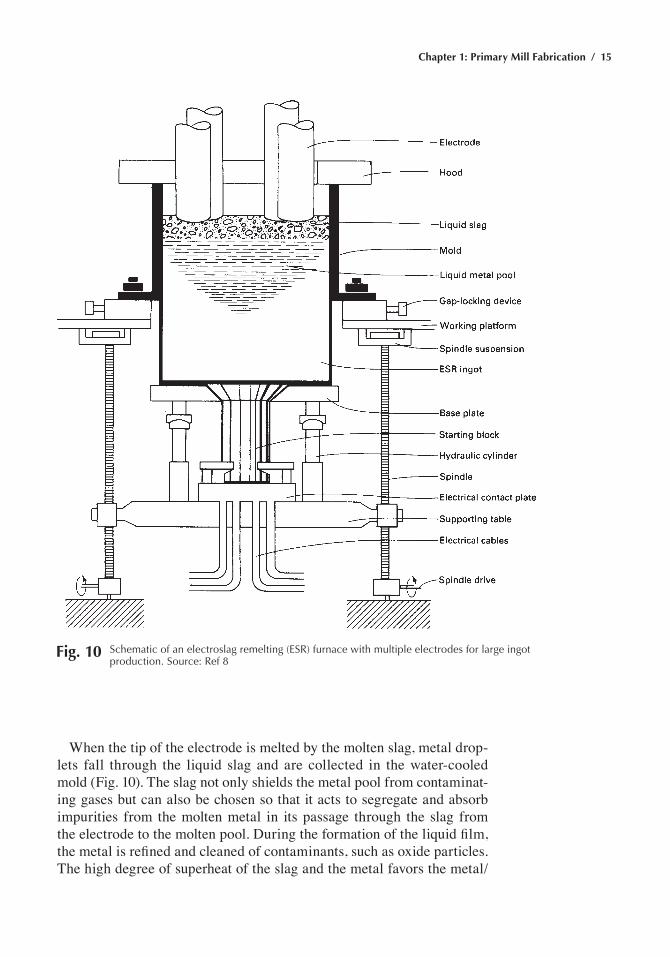
Electroslag remelting (ESR) is another secondary refining process (Fig. 10), where a consumable electrode is melted by immersion in a molten flux (slag) consisting primarily of fluorspar (CaF2). Heating is generated by an electrical current (usually ac) that flows from the base plate through the liquid slag and the electrode. Oxides may be added to the slag to raise the resistivity (so as to make melting more efficient elec-trically) or to modify the slag chemistry with regard to its reactivity with the metal being melted. Electroslag remelting is similar to VAR, except that ESR is carried out at normal atmospheric pressure and has a greater melting rate than VAR.
Fig. 9 Modern vacuum arc remelting (Var) furnace. (a) 30 ton Var. (b) Operational components: 1, electrode feed drive; 2, furnace chamber; 3, melting power supply; 4, busbars/cables; 5,
electrode ram; 6, water jacket with crucible; 7, vacuum suction port; 8, X-Y adjustment; 9, load cell system. Courtesy of aLD Vacuum technologies Gmbh. Source: ref 7
Chapter 1: Primary Mill Fabrication / 15
When the tip of the electrode is melted by the molten slag, metal drop-lets fall through the liquid slag and are collected in the water-cooled mold (Fig. 10). The slag not only shields the metal pool from contaminat-ing gases but can also be chosen so that it acts to segregate and absorb impurities from the molten metal in its passage through the slag from the electrode to the molten pool. During the formation of the liquid film, the metal is refined and cleaned of contaminants, such as oxide particles. The high degree of superheat of the slag and the metal favors the metal/
Fig. 10 Schematic of an electroslag remelting (eSr) furnace with multiple electrodes for large ingot production. Source: ref 8
16 / Metals Fabrication—Understanding the Basics
slag reaction. Melting in the form of metal droplets greatly increases the metal/slag interface surface area. The intensive reactions between metal and slag refine the melt. The remaining inclusions are very small and are evenly distributed in the remelted ingot.
The absence of macrosegregation or heterogeneity in the distribution of nonmetallic inclusions in ESR ingots justifies the additional cost of remelt-ing. In addition, the very clean and smooth surface of ESR ingots helps to reduce production costs, because surface conditioning before hot working is not necessary. Another special feature of the ESR process, as in VAR, is the directional solidification of the ingot from bottom to top. The mac-rostructure is marked by an extraordinarily high density and homogeneity as well as by the absence of segregations and shrinkage cavities.
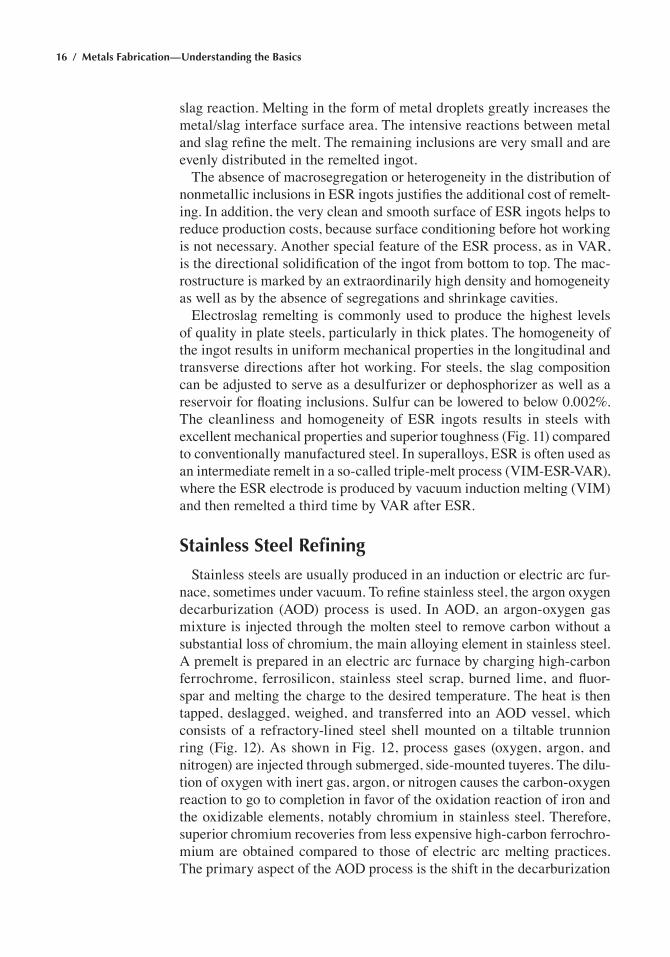
Electroslag remelting is commonly used to produce the highest levels of quality in plate steels, particularly in thick plates. The homogeneity of the ingot results in uniform mechanical properties in the longitudinal and transverse directions after hot working. For steels, the slag composition can be adjusted to serve as a desulfurizer or dephosphorizer as well as a reservoir for floating inclusions. Sulfur can be lowered to below 0.002%. The cleanliness and homogeneity of ESR ingots results in steels with excellent mechanical properties and superior toughness (Fig. 11) compared to conventionally manufactured steel. In superalloys, ESR is often used as an intermediate remelt in a so-called triple-melt process (VIM-ESR-VAR), where the ESR electrode is produced by vacuum induction melting (VIM) and then remelted a third time by VAR after ESR.
Stainless Steel Refining
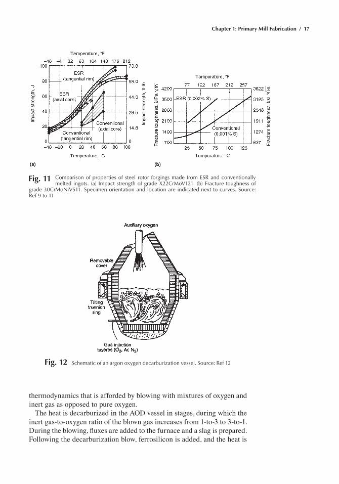
Stainless steels are usually produced in an induction or electric arc fur-nace, sometimes under vacuum. To refine stainless steel, the argon oxygen decarburization (AOD) process is used. In AOD, an argon-oxygen gas mixture is injected through the molten steel to remove carbon without a substantial loss of chromium, the main alloying element in stainless steel. A premelt is prepared in an electric arc furnace by charging high-carbon ferrochrome, ferrosilicon, stainless steel scrap, burned lime, and fluor-spar and melting the charge to the desired temperature. The heat is then tapped, deslagged, weighed, and transferred into an AOD vessel, which consists of a refractory-lined steel shell mounted on a tiltable trunnion ring (Fig. 12). As shown in Fig. 12, process gases (oxygen, argon, and nitrogen) are injected through submerged, side-mounted tuyeres. The dilu-tion of oxygen with inert gas, argon, or nitrogen causes the carbon-oxygen reaction to go to completion in favor of the oxidation reaction of iron and the oxidizable elements, notably chromium in stainless steel. Therefore, superior chromium recoveries from less expensive high-carbon ferrochro-mium are obtained compared to those of electric arc melting practices. The primary aspect of the AOD process is the shift in the decarburization
Chapter 1: Primary Mill Fabrication / 17
thermodynamics that is afforded by blowing with mixtures of oxygen and inert gas as opposed to pure oxygen.
The heat is decarburized in the AOD vessel in stages, during which the inert gas-to-oxygen ratio of the blown gas increases from 1-to-3 to 3-to-1. During the blowing, fluxes are added to the furnace and a slag is prepared. Following the decarburization blow, ferrosilicon is added, and the heat is
Fig. 12 Schematic of an argon oxygen decarburization vessel. Source: ref 12
Fig. 11 Comparison of properties of steel rotor forgings made from eSr and conventionally melted ingots. (a) Impact strength of grade X22CrMoV121. (b) Fracture toughness of
grade 30CrMoNiV511. Specimen orientation and location are indicated next to curves. Source: ref 9 to 11
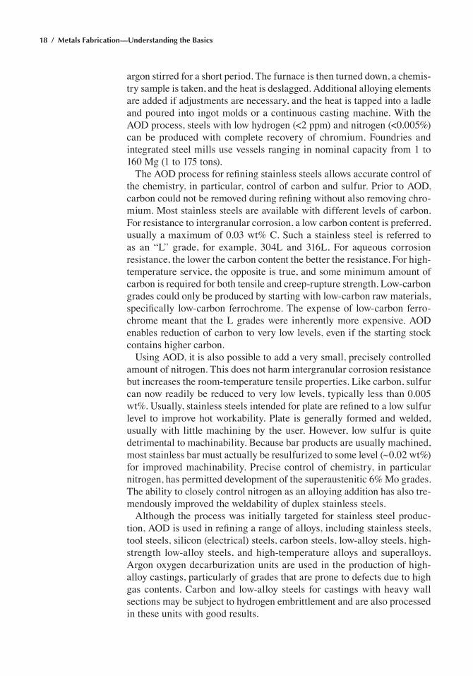
18 / Metals Fabrication—Understanding the Basics
argon stirred for a short period. The furnace is then turned down, a chemis-try sample is taken, and the heat is deslagged. Additional alloying elements are added if adjustments are necessary, and the heat is tapped into a ladle and poured into ingot molds or a continuous casting machine. With the AOD process, steels with low hydrogen (<2 ppm) and nitrogen (<0.005%) can be produced with complete recovery of chromium. Foundries and integrated steel mills use vessels ranging in nominal capacity from 1 to 160 Mg (1 to 175 tons).
The AOD process for refining stainless steels allows accurate control of the chemistry, in particular, control of carbon and sulfur. Prior to AOD, carbon could not be removed during refining without also removing chro-mium. Most stainless steels are available with different levels of carbon. For resistance to intergranular corrosion, a low carbon content is preferred, usually a maximum of 0.03 wt% C. Such a stainless steel is referred to as an “L” grade, for example, 304L and 316L. For aqueous corrosion resistance, the lower the carbon content the better the resistance. For high-temperature service, the opposite is true, and some minimum amount of carbon is required for both tensile and creep-rupture strength. Low-carbon grades could only be produced by starting with low-carbon raw materials, specifically low-carbon ferrochrome. The expense of low-carbon ferro-chrome meant that the L grades were inherently more expensive. AOD enables reduction of carbon to very low levels, even if the starting stock contains higher carbon.
Using AOD, it is also possible to add a very small, precisely controlled amount of nitrogen. This does not harm intergranular corrosion resistance but increases the room-temperature tensile properties. Like carbon, sulfur can now readily be reduced to very low levels, typically less than 0.005 wt%. Usually, stainless steels intended for plate are refined to a low sulfur level to improve hot workability. Plate is generally formed and welded, usually with little machining by the user. However, low sulfur is quite detrimental to machinability. Because bar products are usually machined, most stainless bar must actually be resulfurized to some level (~0.02 wt%) for improved machinability. Precise control of chemistry, in particular nitrogen, has permitted development of the superaustenitic 6% Mo grades. The ability to closely control nitrogen as an alloying addition has also tre-mendously improved the weldability of duplex stainless steels.
Although the process was initially targeted for stainless steel produc-tion, AOD is used in refining a range of alloys, including stainless steels, tool steels, silicon (electrical) steels, carbon steels, low-alloy steels, high-strength low-alloy steels, and high-temperature alloys and superalloys. Argon oxygen decarburization units are used in the production of high-alloy castings, particularly of grades that are prone to defects due to high gas contents. Carbon and low-alloy steels for castings with heavy wall sections may be subject to hydrogen embrittlement and are also processed in these units with good results.
Chapter 1: Primary Mill Fabrication / 19
Ingot Casting
After the ladle refining operations are complete, the liquid steel is cast in molds to produce ingots or continuously cast in a continuous casting machine. Although ingot casting has been the traditional method, continu-ous casting has rapidly evolved as the method of choice because of cost and quality advantages. During ingot casting, the ladle is moved by an overhead crane so that it can be tapped or teemed into individual upright-standing molds on rail cars. Ingot molds are slightly tapered, as shown in Fig. 13, for easier removal of the ingots after solidification. After stripping from the molds, the hot ingots are transferred to soaking pits where they are reheated for hot rolling.
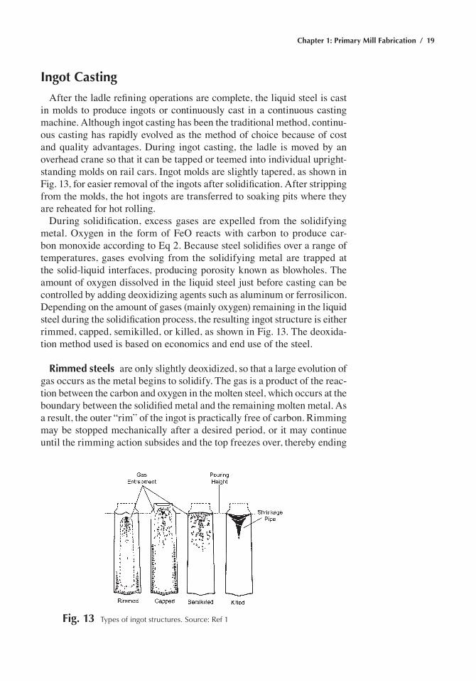
During solidification, excess gases are expelled from the solidifying metal. Oxygen in the form of FeO reacts with carbon to produce car-bon monoxide according to Eq 2. Because steel solidifies over a range of temperatures, gases evolving from the solidifying metal are trapped at the solid-liquid interfaces, producing porosity known as blowholes. The amount of oxygen dissolved in the liquid steel just before casting can be controlled by adding deoxidizing agents such as aluminum or ferrosilicon. Depending on the amount of gases (mainly oxygen) remaining in the liquid steel during the solidification process, the resulting ingot structure is either rimmed, capped, semikilled, or killed, as shown in Fig. 13. The deoxida-tion method used is based on economics and end use of the steel.
Rimmed steels are only slightly deoxidized, so that a large evolution of gas occurs as the metal begins to solidify. The gas is a product of the reac-tion between the carbon and oxygen in the molten steel, which occurs at the boundary between the solidified metal and the remaining molten metal. As a result, the outer “rim” of the ingot is practically free of carbon. Rimming may be stopped mechanically after a desired period, or it may continue until the rimming action subsides and the top freezes over, thereby ending
Fig. 13 types of ingot structures. Source: ref 1
20 / Metals Fabrication—Understanding the Basics
all gas evolution. The center portion of the ingot, which solidifies after the rimming ceases, has a carbon composition somewhat above that of the original molten metal as a result of the segregation tendencies. The low-carbon surface layer of rimmed steel is very ductile. Proper control of the rimming action will result in a very sound surface for subsequent rolling. Consequently, rimmed grades are particularly adaptable to applications involving cold forming and where the surface finish is of prime impor-tance. The presence of an appreciable percentage of carbon or manganese decreases the oxygen available for the rimming action. If the carbon con-tent is greater than 0.25 wt% and the manganese is greater than 0.60 wt%, the action will be very sluggish or nonexistent. If a rim is formed, it will be quite thin and porous. As a result, the cold forming properties and surface quality are seriously impaired. It is therefore standard practice to specify rimmed steel only for grades with low percentages of carbon and manganese. Rimmed steel is cheaper to produce because the top portion of the ingot does not have a large gas cavity that must be scrapped, which means the yield is higher.
Capped steels are much the same as rimmed steels except that the duration of the rimming action is curtailed. A deoxidizer is usually added during pouring of the ingot, with the result that a sufficient amount of gas is entrapped in the solidifying steel to cause the metal to occupy a larger volume in the mold. The rising metal contacts the cap, thereby stopping the action. A similar effect can be obtained by adding ferrosilicon or alu-minum to the ingot top after the ingot has cooled for the desired time. Rimming times of 1 to 3 min prior to capping are most common. Capped steels have a thin, low-carbon rim that imparts the surface and cold form-ing characteristics of rimmed steel. The remainder of the cross section approaches the uniformity typical of semikilled steels.
Semikilled steels are intermediate in deoxidation between the rimmed and killed grades. Sufficient oxygen is retained so that its evolution coun-teracts the shrinkage on solidification, but there is no rimming action. Consequently, the composition is more uniform than rimmed steel, but there is also a greater possibility of segregation than in killed steels. Semikilled steels are used where neither the surface nor the cold forming characteristics of rimmed steels nor the greater uniformity of killed steels are essential requirements.
Killed steels are strongly deoxidized and characterized by a relatively high degree of uniformity in composition and properties. The metal shrinks during solidification, forming a cavity or pipe in the extreme upper por-tion of the ingot. Generally, these grades are poured in big-end-up molds. A “hot top” brick is placed on top of the mold before pouring and filled with metal after the ingot is poured. The pipe formed will be confined
Chapter 1: Primary Mill Fabrication / 21
to the hot-top section of the ingot, which is removed by cropping before rolling. The most severe segregation of the ingot will also be removed by cropping. While killed steels are more uniform in composition and properties than any other type, they are nevertheless susceptible to some degree of segregation. As in the other grades, the top center portion of the ingot will exhibit greater segregation than the balance of the ingot. The uniformity of killed steel makes it most suitable for applications involv-ing operations such as forging, piercing, carburizing, and heat treatment. Aluminum-killed steels are widely used for cold rolled sheet that will be used for severe forming or deep drawing. These steels exhibit a minimum of strain aging and have a fine grain size.
Continuous Casting
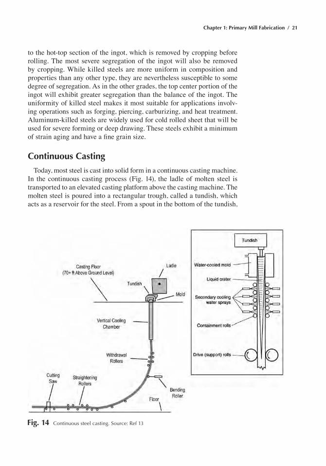
Today, most steel is cast into solid form in a continuous casting machine. In the continuous casting process (Fig. 14), the ladle of molten steel is transported to an elevated casting platform above the casting machine. The molten steel is poured into a rectangular trough, called a tundish, which acts as a reservoir for the steel. From a spout in the bottom of the tundish,
Fig. 14 Continuous steel casting. Source: ref 13
22 / Metals Fabrication—Understanding the Basics
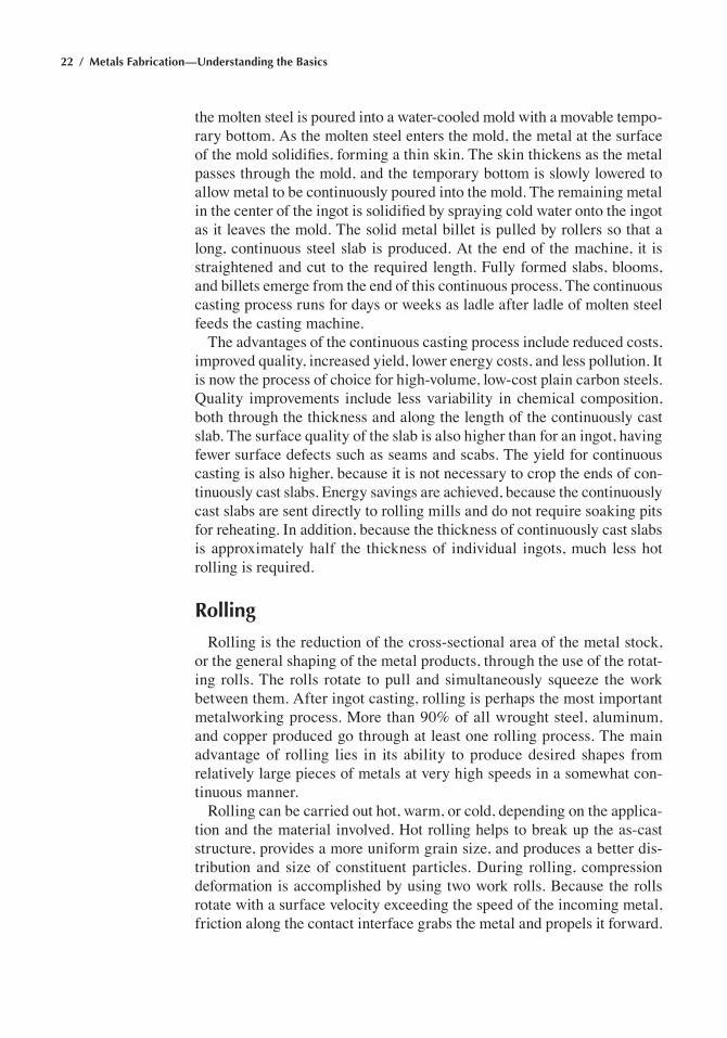
the molten steel is poured into a water-cooled mold with a movable tempo-rary bottom. As the molten steel enters the mold, the metal at the surface of the mold solidifies, forming a thin skin. The skin thickens as the metal passes through the mold, and the temporary bottom is slowly lowered to allow metal to be continuously poured into the mold. The remaining metal in the center of the ingot is solidified by spraying cold water onto the ingot as it leaves the mold. The solid metal billet is pulled by rollers so that a long, continuous steel slab is produced. At the end of the machine, it is straightened and cut to the required length. Fully formed slabs, blooms, and billets emerge from the end of this continuous process. The continuous casting process runs for days or weeks as ladle after ladle of molten steel feeds the casting machine.
The advantages of the continuous casting process include reduced costs, improved quality, increased yield, lower energy costs, and less pollution. It is now the process of choice for high-volume, low-cost plain carbon steels. Quality improvements include less variability in chemical composition, both through the thickness and along the length of the continuously cast slab. The surface quality of the slab is also higher than for an ingot, having fewer surface defects such as seams and scabs. The yield for continuous casting is also higher, because it is not necessary to crop the ends of con-tinuously cast slabs. Energy savings are achieved, because the continuously cast slabs are sent directly to rolling mills and do not require soaking pits for reheating. In addition, because the thickness of continuously cast slabs is approximately half the thickness of individual ingots, much less hot rolling is required.
Rolling
Rolling is the reduction of the cross-sectional area of the metal stock, or the general shaping of the metal products, through the use of the rotat-ing rolls. The rolls rotate to pull and simultaneously squeeze the work between them. After ingot casting, rolling is perhaps the most important metalworking process. More than 90% of all wrought steel, aluminum, and copper produced go through at least one rolling process. The main advantage of rolling lies in its ability to produce desired shapes from relatively large pieces of metals at very high speeds in a somewhat con-tinuous manner.
Rolling can be carried out hot, warm, or cold, depending on the applica-tion and the material involved. Hot rolling helps to break up the as-cast structure, provides a more uniform grain size, and produces a better dis-tribution and size of constituent particles. During rolling, compression deformation is accomplished by using two work rolls. Because the rolls rotate with a surface velocity exceeding the speed of the incoming metal, friction along the contact interface grabs the metal and propels it forward.
Chapter 1: Primary Mill Fabrication / 23
The amount of deformation that can be achieved in a single pass between a given pair of rolls depends on the frictional conditions along the inter-face. If too much deformation is attempted, the rolls will simply skid over stationary metal, while too little deformation per pass results in excessive cost.
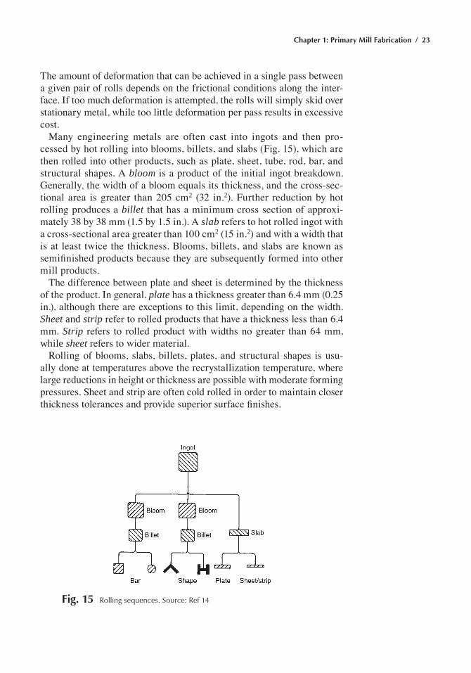
Many engineering metals are often cast into ingots and then pro-cessed by hot rolling into blooms, billets, and slabs (Fig. 15), which are then rolled into other products, such as plate, sheet, tube, rod, bar, and structural shapes. A bloom is a product of the initial ingot breakdown. Generally, the width of a bloom equals its thickness, and the cross-sec-tional area is greater than 205 cm2 (32 in.2). Further reduction by hot rolling produces a billet that has a minimum cross section of approxi-mately 38 by 38 mm (1.5 by 1.5 in.). A slab refers to hot rolled ingot with a cross-sectional area greater than 100 cm2 (15 in.2) and with a width that is at least twice the thickness. Blooms, billets, and slabs are known as semifinished products because they are subsequently formed into other mill products.
The difference between plate and sheet is determined by the thickness of the product. In general, plate has a thickness greater than 6.4 mm (0.25 in.), although there are exceptions to this limit, depending on the width. Sheet and strip refer to rolled products that have a thickness less than 6.4 mm. Strip refers to rolled product with widths no greater than 64 mm, while sheet refers to wider material.
Rolling of blooms, slabs, billets, plates, and structural shapes is usu-ally done at temperatures above the recrystallization temperature, where large reductions in height or thickness are possible with moderate forming pressures. Sheet and strip are often cold rolled in order to maintain closer thickness tolerances and provide superior surface finishes.
Fig. 15 rolling sequences. Source: ref 14
24 / Metals Fabrication—Understanding the Basics
Types of Rolling Mills
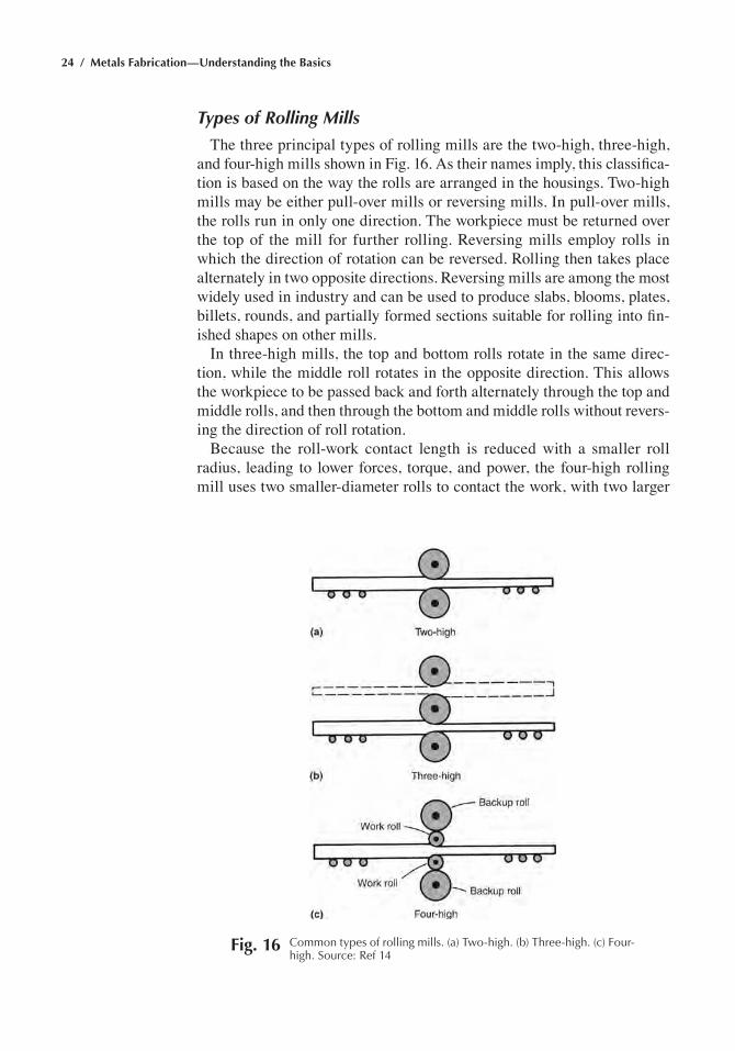
The three principal types of rolling mills are the two-high, three-high, and four-high mills shown in Fig. 16. As their names imply, this classifica-tion is based on the way the rolls are arranged in the housings. Two-high mills may be either pull-over mills or reversing mills. In pull-over mills, the rolls run in only one direction. The workpiece must be returned over the top of the mill for further rolling. Reversing mills employ rolls in which the direction of rotation can be reversed. Rolling then takes place alternately in two opposite directions. Reversing mills are among the most widely used in industry and can be used to produce slabs, blooms, plates, billets, rounds, and partially formed sections suitable for rolling into fin-ished shapes on other mills.
In three-high mills, the top and bottom rolls rotate in the same direc-tion, while the middle roll rotates in the opposite direction. This allows the workpiece to be passed back and forth alternately through the top and middle rolls, and then through the bottom and middle rolls without revers-ing the direction of roll rotation.
Because the roll-work contact length is reduced with a smaller roll radius, leading to lower forces, torque, and power, the four-high rolling mill uses two smaller-diameter rolls to contact the work, with two larger
Fig. 16 Common types of rolling mills. (a) two-high. (b) three-high. (c) Four-high. Source: ref 14
Chapter 1: Primary Mill Fabrication / 25
backing rolls for support. The larger backup rolls reinforce the smaller work rolls, thus allowing fairly large reductions without excessive amounts of roll deflection. Four-high mills are used to produce wide plates and hot rolled or cold rolled sheet, as well as strip of uniform thickness.
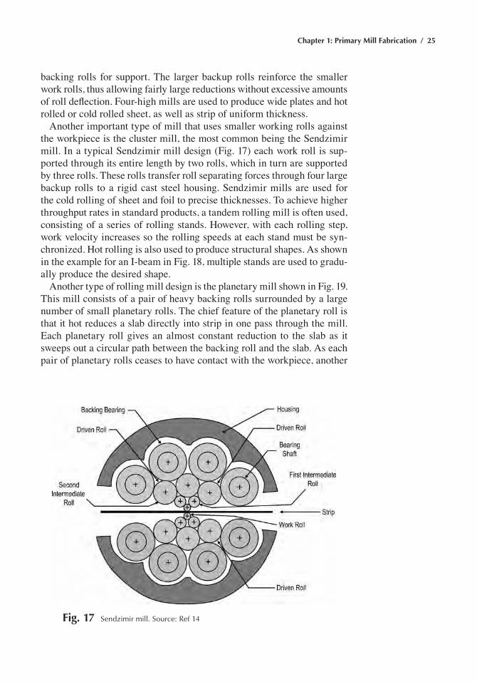
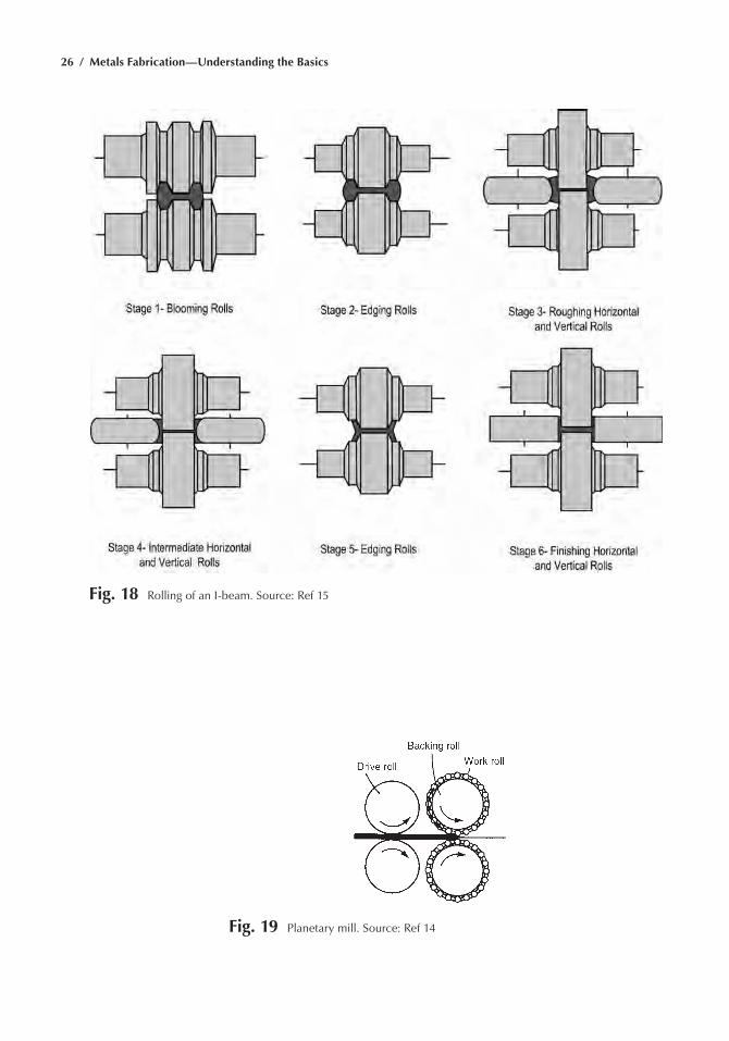
Another important type of mill that uses smaller working rolls against the workpiece is the cluster mill, the most common being the Sendzimir mill. In a typical Sendzimir mill design (Fig. 17) each work roll is sup-ported through its entire length by two rolls, which in turn are supported by three rolls. These rolls transfer roll separating forces through four large backup rolls to a rigid cast steel housing. Sendzimir mills are used for the cold rolling of sheet and foil to precise thicknesses. To achieve higher throughput rates in standard products, a tandem rolling mill is often used, consisting of a series of rolling stands. However, with each rolling step, work velocity increases so the rolling speeds at each stand must be syn-chronized. Hot rolling is also used to produce structural shapes. As shown in the example for an I-beam in Fig. 18, multiple stands are used to gradu-ally produce the desired shape.
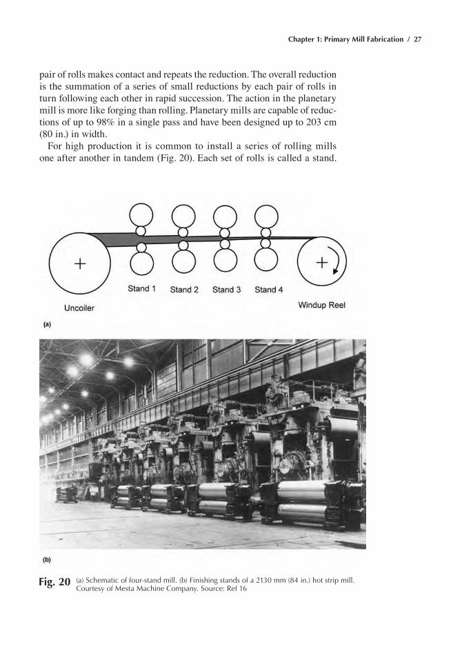
Another type of rolling mill design is the planetary mill shown in Fig. 19. This mill consists of a pair of heavy backing rolls surrounded by a large number of small planetary rolls. The chief feature of the planetary roll is that it hot reduces a slab directly into strip in one pass through the mill. Each planetary roll gives an almost constant reduction to the slab as it sweeps out a circular path between the backing roll and the slab. As each pair of planetary rolls ceases to have contact with the workpiece, another
Fig. 17 Sendzimir mill. Source: ref 14
26 / Metals Fabrication—Understanding the Basics
Fig. 18 rolling of an I-beam. Source: ref 15
Fig. 19 planetary mill. Source: ref 14
Chapter 1: Primary Mill Fabrication / 27
pair of rolls makes contact and repeats the reduction. The overall reduction is the summation of a series of small reductions by each pair of rolls in turn following each other in rapid succession. The action in the planetary mill is more like forging than rolling. Planetary mills are capable of reduc-tions of up to 98% in a single pass and have been designed up to 203 cm (80 in.) in width.
For high production it is common to install a series of rolling mills one after another in tandem (Fig. 20). Each set of rolls is called a stand.
Fig. 20 (a) Schematic of four-stand mill. (b) Finishing stands of a 2130 mm (84 in.) hot strip mill. Courtesy of Mesta Machine Company. Source: ref 16
28 / Metals Fabrication—Understanding the Basics
Because a different reduction is taken at each stand, the strip will be mov-ing at different velocities at each stage in the mill. The speed of each set of rolls is synchronized so that each successive stand takes the strip at a speed equal to the delivery speed of the preceding stand. The uncoiler and windup reel not only accomplish the functions of feeding the stock to the rolls and coiling up the final product but can also be used to supply back tension and front tension to the strip.
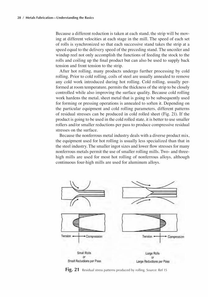
After hot rolling, many products undergo further processing by cold rolling. Prior to cold rolling, coils of steel are usually annealed to remove any cold work introduced during hot rolling. Cold rolling, usually per-formed at room temperature, permits the thickness of the strip to be closely controlled while also improving the surface quality. Because cold rolling work hardens the metal, sheet metal that is going to be subsequently used for forming or pressing operations is annealed to soften it. Depending on the particular equipment and cold rolling parameters, different patterns of residual stresses can be produced in cold rolled sheet (Fig. 21). If the product is going to be used in the cold rolled state, it is better to use smaller rollers and/or smaller reductions per pass to produce compressive residual stresses on the surface.
Because the nonferrous metal industry deals with a diverse product mix, the equipment used for hot rolling is usually less specialized than that in the steel industry. The smaller ingot sizes and lower flow stresses for many nonferrous metals permit the use of smaller rolling mills. Two- and three-high mills are used for most hot rolling of nonferrous alloys, although continuous four-high mills are used for aluminum alloys.
Fig. 21 residual stress patterns produced by rolling. Source: ref 15
Chapter 1: Primary Mill Fabrication / 29
Rolls
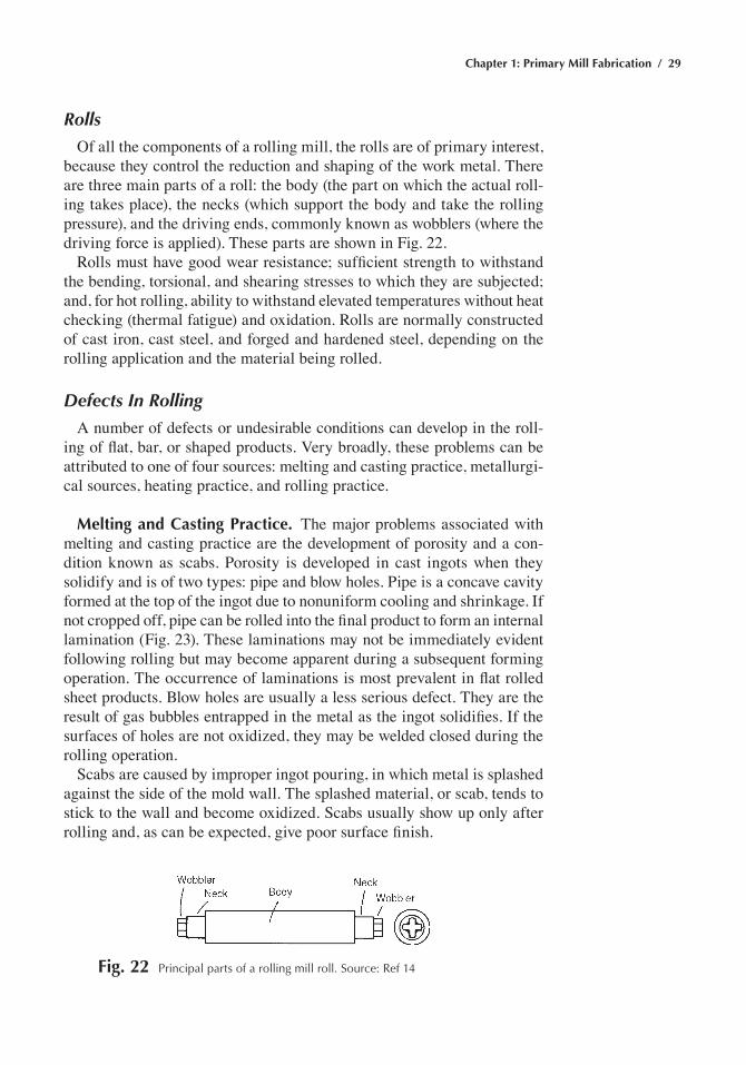
Of all the components of a rolling mill, the rolls are of primary interest, because they control the reduction and shaping of the work metal. There are three main parts of a roll: the body (the part on which the actual roll-ing takes place), the necks (which support the body and take the rolling pressure), and the driving ends, commonly known as wobblers (where the driving force is applied). These parts are shown in Fig. 22.
Rolls must have good wear resistance; sufficient strength to withstand the bending, torsional, and shearing stresses to which they are subjected; and, for hot rolling, ability to withstand elevated temperatures without heat checking (thermal fatigue) and oxidation. Rolls are normally constructed of cast iron, cast steel, and forged and hardened steel, depending on the rolling application and the material being rolled.
Defects In Rolling
A number of defects or undesirable conditions can develop in the roll-ing of flat, bar, or shaped products. Very broadly, these problems can be attributed to one of four sources: melting and casting practice, metallurgi-cal sources, heating practice, and rolling practice.
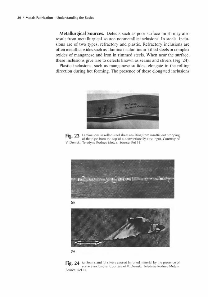
Melting and Casting Practice. The major problems associated with melting and casting practice are the development of porosity and a con-dition known as scabs. Porosity is developed in cast ingots when they solidify and is of two types: pipe and blow holes. Pipe is a concave cavity formed at the top of the ingot due to nonuniform cooling and shrinkage. If not cropped off, pipe can be rolled into the final product to form an internal lamination (Fig. 23). These laminations may not be immediately evident following rolling but may become apparent during a subsequent forming operation. The occurrence of laminations is most prevalent in flat rolled sheet products. Blow holes are usually a less serious defect. They are the result of gas bubbles entrapped in the metal as the ingot solidifies. If the surfaces of holes are not oxidized, they may be welded closed during the rolling operation.
Scabs are caused by improper ingot pouring, in which metal is splashed against the side of the mold wall. The splashed material, or scab, tends to stick to the wall and become oxidized. Scabs usually show up only after rolling and, as can be expected, give poor surface finish.
Fig. 22 principal parts of a rolling mill roll. Source: ref 14
30 / Metals Fabrication—Understanding the Basics
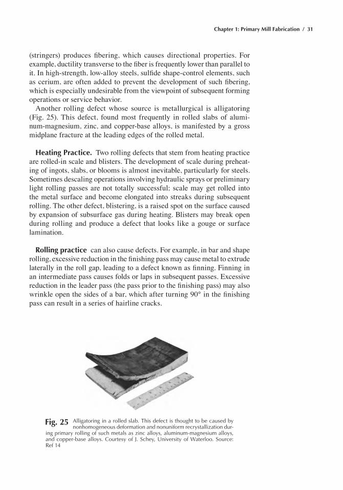
Metallurgical Sources. Defects such as poor surface finish may also result from metallurgical source nonmetallic inclusions. In steels, inclu-sions are of two types, refractory and plastic. Refractory inclusions are often metallic oxides such as alumina in aluminum-killed steels or complex oxides of manganese and iron in rimmed steels. When near the surface, these inclusions give rise to defects known as seams and slivers (Fig. 24).
Plastic inclusions, such as manganese sulfides, elongate in the rolling direction during hot forming. The presence of these elongated inclusions
Fig. 23 Laminations in rolled steel sheet resulting from insufficient cropping of the pipe from the top of a conventionally cast ingot. Courtesy of
V. Demski, teledyne rodney Metals. Source: ref 14
Fig. 24 (a) Seams and (b) slivers caused in rolled material by the presence of surface inclusions. Courtesy of V. Demski, teledyne rodney Metals.
Source: ref 14
Chapter 1: Primary Mill Fabrication / 31
(stringers) produces fibering, which causes directional properties. For example, ductility transverse to the fiber is frequently lower than parallel to it. In high-strength, low-alloy steels, sulfide shape-control elements, such as cerium, are often added to prevent the development of such fibering, which is especially undesirable from the viewpoint of subsequent forming operations or service behavior.
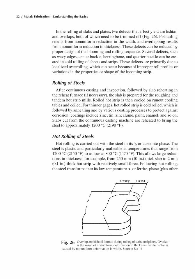
Another rolling defect whose source is metallurgical is alligatoring (Fig. 25). This defect, found most frequently in rolled slabs of alumi-num-magnesium, zinc, and copper-base alloys, is manifested by a gross midplane fracture at the leading edges of the rolled metal.
Heating Practice. Two rolling defects that stem from heating practice are rolled-in scale and blisters. The development of scale during preheat-ing of ingots, slabs, or blooms is almost inevitable, particularly for steels. Sometimes descaling operations involving hydraulic sprays or preliminary light rolling passes are not totally successful; scale may get rolled into the metal surface and become elongated into streaks during subsequent rolling. The other defect, blistering, is a raised spot on the surface caused by expansion of subsurface gas during heating. Blisters may break open during rolling and produce a defect that looks like a gouge or surface lamination.
Rolling practice can also cause defects. For example, in bar and shape rolling, excessive reduction in the finishing pass may cause metal to extrude laterally in the roll gap, leading to a defect known as finning. Finning in an intermediate pass causes folds or laps in subsequent passes. Excessive reduction in the leader pass (the pass prior to the finishing pass) may also wrinkle open the sides of a bar, which after turning 90° in the finishing pass can result in a series of hairline cracks.
Fig. 25 alligatoring in a rolled slab. this defect is thought to be caused by nonhomogeneous deformation and nonuniform recrystallization dur-
ing primary rolling of such metals as zinc alloys, aluminum-magnesium alloys, and copper-base alloys. Courtesy of J. Schey, University of Waterloo. Source: ref 14
32 / Metals Fabrication—Understanding the Basics
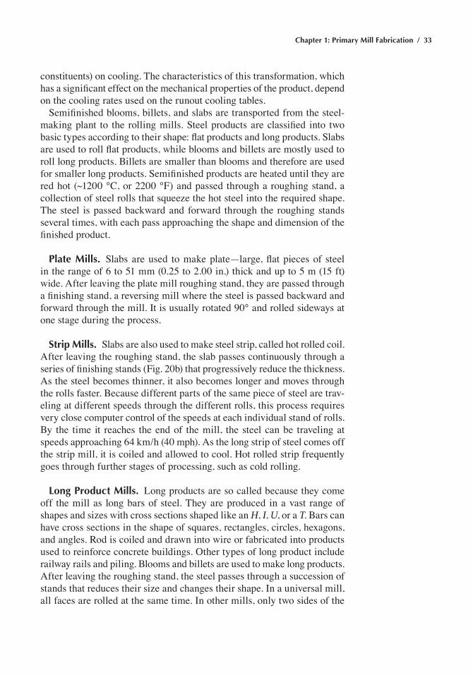
In the rolling of slabs and plates, two defects that affect yield are fishtail and overlaps, both of which need to be trimmed off (Fig. 26). Fishtailing results from nonuniform reduction in the width, and overlapping results from nonuniform reduction in thickness. These defects can be reduced by proper design of the blooming and rolling sequence. Several defects, such as wavy edges, center buckle, herringbone, and quarter buckle can be cre-ated in cold rolling of sheets and strips. These defects are primarily due to localized overrolling, which can occur because of improper roll profiles or variations in the properties or shape of the incoming strip.
Rolling of Steels
After continuous casting and inspection, followed by slab reheating in the reheat furnace (if necessary), the slab is prepared for the roughing and tandem hot strip mills. Rolled hot strip is then cooled on runout cooling tables and coiled. For thinner gages, hot rolled strip is cold rolled, which is followed by annealing and by various coating processes to protect against corrosion; coatings include zinc, tin, zincalume, paint, enamel, and so on. Slabs cut from the continuous casting machine are reheated to bring the steel to approximately 1200 °C (2190 °F).
Hot Rolling of Steels
Hot rolling is carried out with the steel in its γ, or austenite phase. The steel is plastic and particularly malleable at temperatures that range from 1200 °C (2150 °F) to as low as 800 °C (1470 °F). This allows large reduc-tions in thickness, for example, from 250 mm (10 in.) thick slab to 2 mm (0.1 in.) thick hot strip with relatively small force. Following hot rolling, the steel transforms into its low-temperature α, or ferrite, phase (plus other
Fig. 26 Overlap and fishtail formed during rolling of slabs and plates. Overlap is the result of nonuniform deformation in thickness, while fishtail is
caused by nonuniform deformation in width. Source: ref 14
Chapter 1: Primary Mill Fabrication / 33
constituents) on cooling. The characteristics of this transformation, which has a significant effect on the mechanical properties of the product, depend on the cooling rates used on the runout cooling tables.
Semifinished blooms, billets, and slabs are transported from the steel-making plant to the rolling mills. Steel products are classified into two basic types according to their shape: flat products and long products. Slabs are used to roll flat products, while blooms and billets are mostly used to roll long products. Billets are smaller than blooms and therefore are used for smaller long products. Semifinished products are heated until they are red hot (~1200 °C, or 2200 °F) and passed through a roughing stand, a collection of steel rolls that squeeze the hot steel into the required shape. The steel is passed backward and forward through the roughing stands several times, with each pass approaching the shape and dimension of the finished product.
Plate Mills. Slabs are used to make plate—large, flat pieces of steel in the range of 6 to 51 mm (0.25 to 2.00 in.) thick and up to 5 m (15 ft) wide. After leaving the plate mill roughing stand, they are passed through a finishing stand, a reversing mill where the steel is passed backward and forward through the mill. It is usually rotated 90° and rolled sideways at one stage during the process.
Strip Mills. Slabs are also used to make steel strip, called hot rolled coil. After leaving the roughing stand, the slab passes continuously through a series of finishing stands (Fig. 20b) that progressively reduce the thickness. As the steel becomes thinner, it also becomes longer and moves through the rolls faster. Because different parts of the same piece of steel are trav-eling at different speeds through the different rolls, this process requires very close computer control of the speeds at each individual stand of rolls. By the time it reaches the end of the mill, the steel can be traveling at speeds approaching 64 km/h (40 mph). As the long strip of steel comes off the strip mill, it is coiled and allowed to cool. Hot rolled strip frequently goes through further stages of processing, such as cold rolling.
Long Product Mills. Long products are so called because they come off the mill as long bars of steel. They are produced in a vast range of shapes and sizes with cross sections shaped like an H, I, U, or a T. Bars can have cross sections in the shape of squares, rectangles, circles, hexagons, and angles. Rod is coiled and drawn into wire or fabricated into products used to reinforce concrete buildings. Other types of long product include railway rails and piling. Blooms and billets are used to make long products. After leaving the roughing stand, the steel passes through a succession of stands that reduces their size and changes their shape. In a universal mill, all faces are rolled at the same time. In other mills, only two sides of the
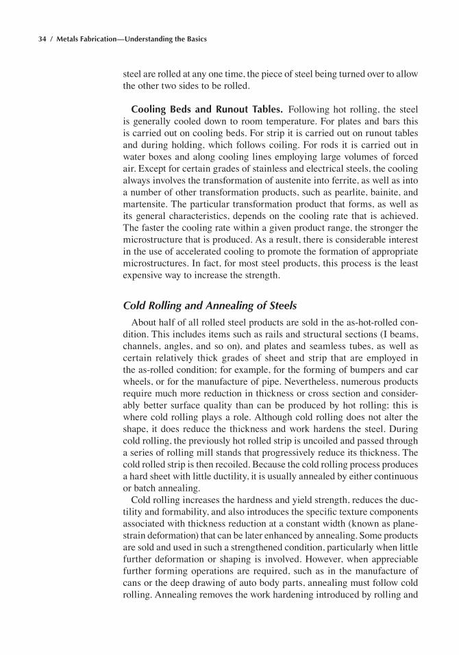
34 / Metals Fabrication—Understanding the Basics
steel are rolled at any one time, the piece of steel being turned over to allow the other two sides to be rolled.
Cooling Beds and Runout Tables. Following hot rolling, the steel is generally cooled down to room temperature. For plates and bars this is carried out on cooling beds. For strip it is carried out on runout tables and during holding, which follows coiling. For rods it is carried out in water boxes and along cooling lines employing large volumes of forced air. Except for certain grades of stainless and electrical steels, the cooling always involves the transformation of austenite into ferrite, as well as into a number of other transformation products, such as pearlite, bainite, and martensite. The particular transformation product that forms, as well as its general characteristics, depends on the cooling rate that is achieved. The faster the cooling rate within a given product range, the stronger the microstructure that is produced. As a result, there is considerable interest in the use of accelerated cooling to promote the formation of appropriate microstructures. In fact, for most steel products, this process is the least expensive way to increase the strength.
Cold Rolling and Annealing of Steels
About half of all rolled steel products are sold in the as-hot-rolled con-dition. This includes items such as rails and structural sections (I beams, channels, angles, and so on), and plates and seamless tubes, as well as certain relatively thick grades of sheet and strip that are employed in the as-rolled condition; for example, for the forming of bumpers and car wheels, or for the manufacture of pipe. Nevertheless, numerous products require much more reduction in thickness or cross section and consider-ably better surface quality than can be produced by hot rolling; this is where cold rolling plays a role. Although cold rolling does not alter the shape, it does reduce the thickness and work hardens the steel. During cold rolling, the previously hot rolled strip is uncoiled and passed through a series of rolling mill stands that progressively reduce its thickness. The cold rolled strip is then recoiled. Because the cold rolling process produces a hard sheet with little ductility, it is usually annealed by either continuous or batch annealing.
Cold rolling increases the hardness and yield strength, reduces the duc-tility and formability, and also introduces the specific texture components associated with thickness reduction at a constant width (known as plane-strain deformation) that can be later enhanced by annealing. Some products are sold and used in such a strengthened condition, particularly when little further deformation or shaping is involved. However, when appreciable further forming operations are required, such as in the manufacture of cans or the deep drawing of auto body parts, annealing must follow cold rolling. Annealing removes the work hardening introduced by rolling and
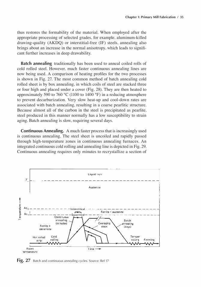
Chapter 1: Primary Mill Fabrication / 35
thus restores the formability of the material. When employed after the appropriate processing of selected grades, for example, aluminum-killed drawing-quality (AKDQ) or interstitial-free (IF) steels, annealing also brings about an increase in the normal anisotropy, which leads to signifi-cant further increases in deep drawability.
Batch annealing traditionally has been used to anneal coiled rolls of cold rolled steel. However, much faster continuous annealing lines are now being used. A comparison of heating profiles for the two processes is shown in Fig. 27. The most common method of batch annealing cold rolled sheet is by box annealing, in which coils of steel are stacked three or four high and placed under a cover (Fig. 28). They are then heated to approximately 590 to 760 °C (1100 to 1400 °F) in a reducing atmosphere to prevent decarburization. Very slow heat-up and cool-down rates are associated with batch annealing, resulting in a coarse pearlitic structure. Because almost all of the carbon in the steel is precipitated as pearlite, steel produced in this manner normally has a low susceptibility to strain aging. Batch annealing is slow, requiring several days.
Continuous Annealing. A much faster process that is increasingly used is continuous annealing. The steel sheet is uncoiled and rapidly passed through high-temperature zones in continuous annealing furnaces. An integrated continuous cold rolling and annealing line is depicted in Fig. 29. Continuous annealing requires only minutes to recrystallize a section of
Fig. 27 Batch and continuous annealing cycles. Source: ref 17
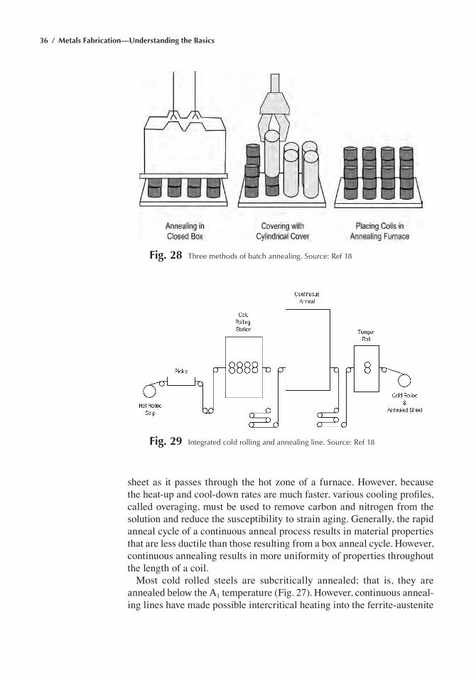
36 / Metals Fabrication—Understanding the Basics
sheet as it passes through the hot zone of a furnace. However, because the heat-up and cool-down rates are much faster, various cooling profiles, called overaging, must be used to remove carbon and nitrogen from the solution and reduce the susceptibility to strain aging. Generally, the rapid anneal cycle of a continuous anneal process results in material properties that are less ductile than those resulting from a box anneal cycle. However, continuous annealing results in more uniformity of properties throughout the length of a coil.
Most cold rolled steels are subcritically annealed; that is, they are annealed below the A1 temperature (Fig. 27). However, continuous anneal-ing lines have made possible intercritical heating into the ferrite-austenite
Fig. 28 three methods of batch annealing. Source: ref 18
Fig. 29 Integrated cold rolling and annealing line. Source: ref 18
Chapter 1: Primary Mill Fabrication / 37
field, with cooling that is rapid enough to cause the austenite to transform to martensite. As a result, early yielding is continuous and occurs with high rates of strain hardening. Intercritically annealed steels with ferrite-martensite microstructures are referred to as dual-phase steels that have strength levels in the 345 to 550 MPa (50 to 80 ksi) range.
Rimmed or capped ingot cast steel (Fig. 15) traditionally has been used because of its lower price. However, rimmed and capped steels are suscep-tible to quench and strain aging. Strain aging and quench aging can produce localized deformation and discontinuous yielding. This causes stretcher strains during forming and unacceptable surface finishes on formed parts. To eliminate stretcher strains, cold rolled and annealed sheet steels are temper rolled. Temper rolling introduces just enough strain so that the deformed sheet will strain uniformly or continuously. However, the yield point will reappear with time. Where strain aging is to be avoided and/or when exceptional formability is required, steel killed with aluminum is preferred, because nitrogen, a primary contributor to strain aging, is tied up as inert aluminum nitride (AlN) particles. In addition, all continuously cast steel must be fully killed to allow casting.
Another form of cold working is cold drawing. Metal in rod form is drawn through a series of dies that progressively reduce the rod circum-ference to produce wire. The drawing process substantially increases the material tensile strength. Drawn wires can be spun into huge cables for suspension bridges that have very high strengths.
Aluminum Production
To produce pure aluminum, alumina (Al2O3) is first extracted from the mineral bauxite, which contains approximately 50% Al2O3. In the Bayer process, a sodium hydroxide solution is used to precipitate aluminum hydroxide, which is then calcined to form alumina. Alumina is then con-verted to pure aluminum by electrolysis, using the Hall-Héroult process, illustrated in Fig. 30. The cell is lined with carbon cathodes, and consum-able electrodes are gradually fed into the top of the cell. The electrolyte is cryolite (Na3AlF6) with 8 to 10 wt% Al2O3 dissolved in it. The cell operates at temperatures in the range of 955 to 1010 °C (1750 to 1850 °F), with a power rating of 10 to 12 kW◊h/kg aluminum. Pure aluminum (99 wt%) is reduced at the cathode and forms a molten pool in the bottom of the cell, which is drained from the bottom and cast into aluminum ingots. Because impurities, such as iron and silicon, are reduced along with the aluminum, the raw materials used in the Bayer process are care-fully controlled to minimize these metal oxides. Because the production of aluminum takes a lot of electrical energy, and recycling aluminum takes much less energy, a large portion of general-purpose aluminum currently is made from recycled material.
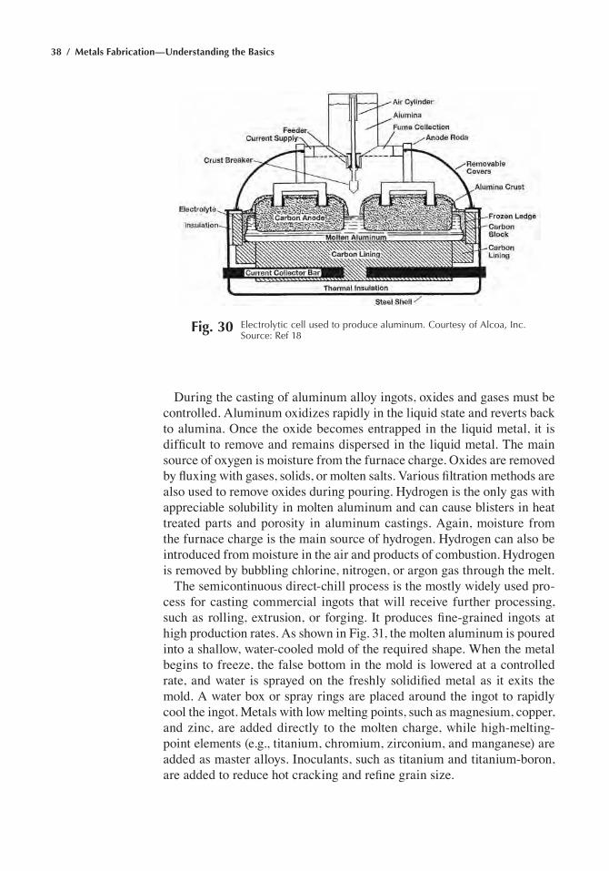
38 / Metals Fabrication—Understanding the Basics
During the casting of aluminum alloy ingots, oxides and gases must be controlled. Aluminum oxidizes rapidly in the liquid state and reverts back to alumina. Once the oxide becomes entrapped in the liquid metal, it is difficult to remove and remains dispersed in the liquid metal. The main source of oxygen is moisture from the furnace charge. Oxides are removed by fluxing with gases, solids, or molten salts. Various filtration methods are also used to remove oxides during pouring. Hydrogen is the only gas with appreciable solubility in molten aluminum and can cause blisters in heat treated parts and porosity in aluminum castings. Again, moisture from the furnace charge is the main source of hydrogen. Hydrogen can also be introduced from moisture in the air and products of combustion. Hydrogen is removed by bubbling chlorine, nitrogen, or argon gas through the melt.
The semicontinuous direct-chill process is the mostly widely used pro-cess for casting commercial ingots that will receive further processing, such as rolling, extrusion, or forging. It produces fine-grained ingots at high production rates. As shown in Fig. 31, the molten aluminum is poured into a shallow, water-cooled mold of the required shape. When the metal begins to freeze, the false bottom in the mold is lowered at a controlled rate, and water is sprayed on the freshly solidified metal as it exits the mold. A water box or spray rings are placed around the ingot to rapidly cool the ingot. Metals with low melting points, such as magnesium, copper, and zinc, are added directly to the molten charge, while high-melting-point elements (e.g., titanium, chromium, zirconium, and manganese) are added as master alloys. Inoculants, such as titanium and titanium-boron, are added to reduce hot cracking and refine grain size.
Fig. 30 electrolytic cell used to produce aluminum. Courtesy of alcoa, Inc. Source: ref 18
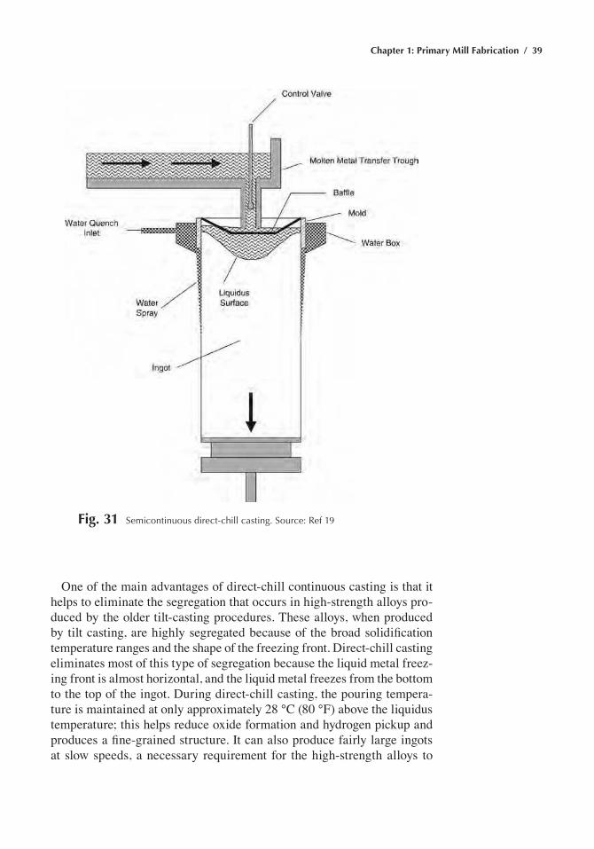
Chapter 1: Primary Mill Fabrication / 39
One of the main advantages of direct-chill continuous casting is that it helps to eliminate the segregation that occurs in high-strength alloys pro-duced by the older tilt-casting procedures. These alloys, when produced by tilt casting, are highly segregated because of the broad solidification temperature ranges and the shape of the freezing front. Direct-chill casting eliminates most of this type of segregation because the liquid metal freez-ing front is almost horizontal, and the liquid metal freezes from the bottom to the top of the ingot. During direct-chill casting, the pouring tempera-ture is maintained at only approximately 28 °C (80 °F) above the liquidus temperature; this helps reduce oxide formation and hydrogen pickup and produces a fine-grained structure. It can also produce fairly large ingots at slow speeds, a necessary requirement for the high-strength alloys to
Fig. 31 Semicontinuous direct-chill casting. Source: ref 19
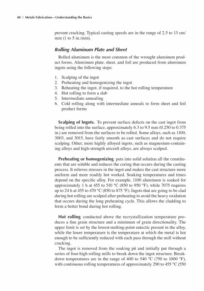
40 / Metals Fabrication—Understanding the Basics
prevent cracking. Typical casting speeds are in the range of 2.5 to 13 cm/min (1 to 5 in./min).
Rolling Aluminum Plate and Sheet
Rolled aluminum is the most common of the wrought aluminum prod-uct forms. Aluminum plate, sheet, and foil are produced from aluminum ingots using the following steps:
1. Scalping of the ingot2. Preheating and homogenizing the ingot3. Reheating the ingot, if required, to the hot rolling temperature4. Hot rolling to form a slab5. Intermediate annealing6. Cold rolling along with intermediate anneals to form sheet and foil
product forms
Scalping of Ingots. To prevent surface defects on the cast ingot from being rolled into the surface, approximately 6.3 to 9.5 mm (0.250 to 0.375 in.) are removed from the surfaces to be rolled. Some alloys, such as 1100, 3003, and 3015, have fairly smooth as-cast surfaces and do not require scalping. Other, more highly alloyed ingots, such as magnesium-contain-ing alloys and high-strength aircraft alloys, are always scalped.
Preheating or homogenizing puts into solid solution all the constitu-ents that are soluble and reduces the coring that occurs during the casting process. It relieves stresses in the ingot and makes the cast structure more uniform and more readily hot worked. Soaking temperatures and times depend on the specific alloy. For example, 1100 aluminum is soaked for approximately 1 h at 455 to 510 °C (850 to 950 °F), while 7075 requires up to 24 h at 455 to 470 °C (850 to 875 °F). Ingots that are going to be clad during hot rolling are scalped after preheating to avoid the heavy oxidation that occurs during the long preheating cycle. This allows the cladding to form a better bond during hot rolling.
Hot rolling conducted above the recrystallization temperature pro-duces a fine grain structure and a minimum of grain directionality. The upper limit is set by the lowest-melting-point eutectic present in the alloy, while the lower temperature is the temperature at which the metal is hot enough to be sufficiently reduced with each pass through the mill without cracking.
The ingot is removed from the soaking pit and initially put through a series of four-high rolling mills to break down the ingot structure. Break-down temperatures are in the range of 400 to 540 °C (750 to 1000 °F), with continuous rolling temperatures of approximately 290 to 455 °C (550
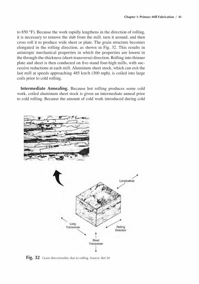
Chapter 1: Primary Mill Fabrication / 41
to 850 °F). Because the work rapidly lengthens in the direction of rolling, it is necessary to remove the slab from the mill, turn it around, and then cross roll it to produce wide sheet or plate. The grain structure becomes elongated in the rolling direction, as shown in Fig. 32. This results in anistropic mechanical properties in which the properties are lowest in the through-the-thickness (short-transverse) direction. Rolling into thinner plate and sheet is then conducted on five-stand four-high mills, with suc-cessive reductions at each mill. Aluminum sheet stock, which can exit the last mill at speeds approaching 485 km/h (300 mph), is coiled into large coils prior to cold rolling.
Intermediate Annealing. Because hot rolling produces some cold work, coiled aluminum sheet stock is given an intermediate anneal prior to cold rolling. Because the amount of cold work introduced during cold
Fig. 32 Grain directionality due to rolling. Source: ref 20
42 / Metals Fabrication—Understanding the Basics
rolling is sufficient to cause recrystallization, annealing not only lowers the strength and increases ductility, it also imparts a fine grain structure.
Cold Rolling. Sheet and foil are cold rolled after hot rolling to produce a much better surface finish and control the strength and ductility through work hardening. Again, four-high mills are used along with lubricants and, if a bright surface finish is required, polished rolls. Depending on the amount of reduction and the final strength required, intermediate anneals are conducted during the cold rolling process. Normally, reductions in the range of 45 to 85% are taken between anneals.
Titanium Production
Titanium for ingot production may be either titanium sponge or reclaimed scrap (revert). In both cases, stringent specifications must be met for control of ingot composition. Most important are the hard, brittle, and refractory titanium oxide, titanium nitride, or complex titanium oxynitride particles that, if retained through subsequent melting operations, could act as crack initiation sites, especially during fatigue loading.
Titanium sponge is manufactured by first chlorinating rutile ore and reducing the resulting TiCl4 with either sodium (Hunter process) or mag-nesium (Kroll process) metal. Sodium-reduced sponge is leached with acid to remove the NaCl by-product of reduction. Magnesium-reduced sponge may be leached, inert gas swept, or vacuum distilled to remove the excess MgCl2 by-product. Vacuum distilling results in lower residual levels of magnesium, hydrogen, and chlorine. Modern melting techniques remove volatile substances from sponge, so that high-quality ingot can be produced regardless of which method is used for production of sponge. Revert makes production of ingot titanium more economical than produc-tion solely from sponge. If properly controlled, revert is fully acceptable and can be used even in materials for critical structural applications.
Titanium Melting
Titanium sponge, revert, and alloy additions are welded together to form an electrode and then vacuum arc melted (VAR). Ingots from the first melt are then used as the consumable electrodes for second-stage melting. Dou-ble melting is used for all applications to ensure an acceptable degree of homogeneity in the resulting product. Triple melting can be used to achieve better uniformity. Triple melting also reduces oxygen-rich or nitrogen-rich inclusions in the microstructure to very low levels by providing an addi-tional melting operation to dissolve them. All melting operations must be done under vacuum to eliminate the introduction of oxygen, nitrogen, and hydrogen. Ingots are normally 650 to 900 mm (26 to 36 in.) in diameter and weigh 3600 to 9000 kg (8000 to 20,000 lb).
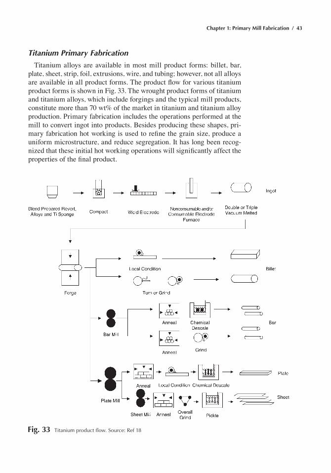
Chapter 1: Primary Mill Fabrication / 43
Titanium Primary Fabrication
Titanium alloys are available in most mill product forms: billet, bar, plate, sheet, strip, foil, extrusions, wire, and tubing; however, not all alloys are available in all product forms. The product flow for various titanium product forms is shown in Fig. 33. The wrought product forms of titanium and titanium alloys, which include forgings and the typical mill products, constitute more than 70 wt% of the market in titanium and titanium alloy production. Primary fabrication includes the operations performed at the mill to convert ingot into products. Besides producing these shapes, pri-mary fabrication hot working is used to refine the grain size, produce a uniform microstructure, and reduce segregation. It has long been recog-nized that these initial hot working operations will significantly affect the properties of the final product.
Fig. 33 titanium product flow. Source: ref 18
44 / Metals Fabrication—Understanding the Basics
As opposed to steel and aluminum ingots, hot rolling is not used for initial ingot breakdown. Instead, as shown in Fig. 33, hot forging opera-tions are used to breakdown the ingot structure. Prior to thermomechanical processing, the as-cast ingot is conditioned by grinding to remove surface defects. The first step in deforming as-cast ingots is a series of slow-speed steps including upset forging, side pressing, and press cogging to help homogenize the structure and break up the transformed β structure. The ingot is electrically preheated and forged at 925 to 1175 °C (1700 to 2150 °F) in large hydraulic presses so that the deformation can be applied slowly to avoid cracking. These operations are initially done above the β transus but significant amounts of deformation are also done below the β transus, but high in the α + β field, to further refine the microstructure to a fine equiaxed α-β structure while avoiding surface rupturing. With modern processing techniques, billet and forged sections readily meet specified tensile properties prior to final forging.
ACKNOWLEDGMENT
Portions of this chapter were adapted from Steel Making Practices and Their Influence on Properties by B. Mishra in Metals Handbook Desk Edi-tion, 2nd ed., ASM International, 1998, and Flat, Bar, and Shape Rolling by G.D. Lahoti in Forming and Forging, Vol 14, ASM Handbook, ASM International, 1988.
REFERENCES
1. H.E. McGannon, The Making, Shaping, and Treating of Steel, 9th ed., United States Steel Corporation, 1971
2. R.A. Higgins, Engineering Metallurgy—Applied Physical Metal-lurgy, 6th ed., Arnold, 1993
3. B. Mishra, Steel Making Practices and Their Influence on Properties, Metals Handbook Desk Edition, 2nd ed., ASM International, 1998
4. W.M. Imrie, Royal Society London Philosophical Transactions, A282, 1976, p 91
5. Vacuum Induction Melting, Casting, Vol 15, ASM Handbook, ASM International, 2008
6. M. Donachie and S. Donachie, Superalloys: A Technical Guide, ASM International, 2002
7. Vacuum Arc Remelting, Casting, Vol 15, ASM Handbook, ASM International, 2008
8. Electroslag Remelting, Casting, Vol 15, ASM Handbook, ASM Inter-national, 2008
9. R. Jauch, A. Choudhury, F. Tince, and H. Steil, Herstellung und Verarbeitung von ESU-Blocken bis zu 160 t, Stahl Eisen, Vol 101, 1981, p 41–44
Chapter 1: Primary Mill Fabrication / 45
10. A. Choudhury, R. Jauch, and F. Tince, Low Frequency Electroslag Remelting of Heavy Ingots with Low Aluminium Content, Proceed-ings of the Sixth International Conference on Vacuum Metallurgy (San Diego), 1979, p 785–794
11. A. Choudhury, R. Jauch, H. Lowenkamp, and F. Tince, Application of the Electroslag Remelting Process for the Production of Heavy Tur-bine Rotors from 12 %-Cr-Steel, Stahl Eisen, Vol 97, 1977, p 857–868
12. Steel Melt Processing, Casting, Vol 15, ASM Handbook, ASM Inter-national, 2008
13. W.F. Smith, Structure and Properties of Engineering Alloys, 2nd ed., McGraw-Hill Inc., 1993
14. G.D. Lahoti and S.L. Semiatin, Flat, Bar, and Shape Rolling, Form-ing and Forging, Vol 14, ASM Handbook, ASM International, 1988
15. S. Kalpakjian, Manufacturing Processes for Engineering Materials, 2nd ed., Addison-Wesley Publishing Company, 1991
16. R.I.L. Guthrie and J.J. Jonas, Steel Processing Technology, Proper-ties and Selection: Irons, Steels, and High-Performance Alloys, Vol 1, ASM Handbook, ASM International, 1990
17. G. Krauss, Microstructures, Processing, and Properties of Steels, Properties and Selections: Irons, Steels, and High-Performance Alloys, Vol 1, ASM Handbook, ASM International, 1990
18. F.C. Campbell, Elements of Metallurgy and Engineering Alloys, ASM International, 2008
19. Aluminum Casting Principles, Lesson 5, Aluminum and Its Alloys, ASM Course, American Society for Metals, 1979
20. K.R. Van Horn, Ed., Aluminum, Vol 1, Properties, Physical Metal-lurgy and Phase Diagrams, American Society for Metals, 1967
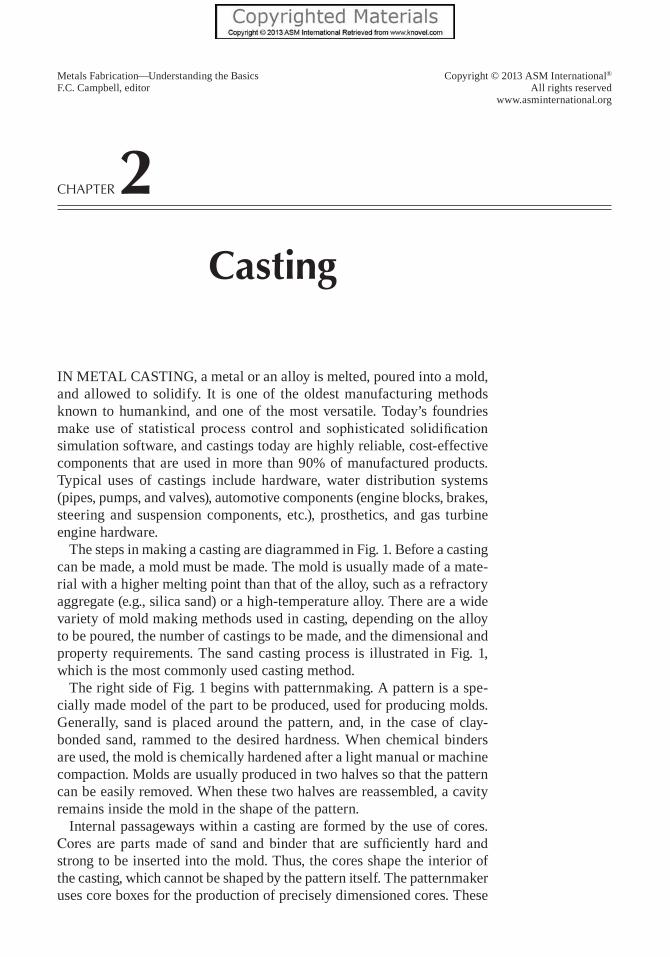
Copyright © 2013 ASM International®
All rights reservedwww.asminternational.org
Metals Fabrication—Understanding the BasicsF.C. Campbell, editor
Chapter 2Casting
In metal castIng, a metal or an alloy is melted, poured into a mold, and allowed to solidify. It is one of the oldest manufacturing methods known to humankind, and one of the most versatile. today’s foundries make use of statistical process control and sophisticated solidification simulation software, and castings today are highly reliable, cost-effective components that are used in more than 90% of manufactured products. typical uses of castings include hardware, water distribution systems (pipes, pumps, and valves), automotive components (engine blocks, brakes, steering and suspension components, etc.), prosthetics, and gas turbine engine hardware.
the steps in making a casting are diagrammed in Fig. 1. Before a casting can be made, a mold must be made. the mold is usually made of a mate-rial with a higher melting point than that of the alloy, such as a refractory aggregate (e.g., silica sand) or a high-temperature alloy. there are a wide variety of mold making methods used in casting, depending on the alloy to be poured, the number of castings to be made, and the dimensional and property requirements. the sand casting process is illustrated in Fig. 1, which is the most commonly used casting method.
the right side of Fig. 1 begins with patternmaking. a pattern is a spe-cially made model of the part to be produced, used for producing molds. generally, sand is placed around the pattern, and, in the case of clay-bonded sand, rammed to the desired hardness. When chemical binders are used, the mold is chemically hardened after a light manual or machine compaction. molds are usually produced in two halves so that the pattern can be easily removed. When these two halves are reassembled, a cavity remains inside the mold in the shape of the pattern.
Internal passageways within a casting are formed by the use of cores. Cores are parts made of sand and binder that are sufficiently hard and strong to be inserted into the mold. thus, the cores shape the interior of the casting, which cannot be shaped by the pattern itself. the patternmaker uses core boxes for the production of precisely dimensioned cores. these
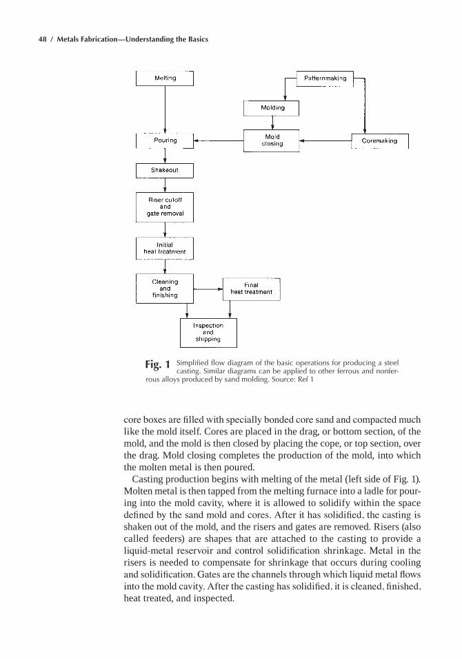
48 / Metals Fabrication—Understanding the Basics
core boxes are filled with specially bonded core sand and compacted much like the mold itself. cores are placed in the drag, or bottom section, of the mold, and the mold is then closed by placing the cope, or top section, over the drag. mold closing completes the production of the mold, into which the molten metal is then poured.
casting production begins with melting of the metal (left side of Fig. 1). molten metal is then tapped from the melting furnace into a ladle for pour-ing into the mold cavity, where it is allowed to solidify within the space defined by the sand mold and cores. After it has solidified, the casting is shaken out of the mold, and the risers and gates are removed. Risers (also called feeders) are shapes that are attached to the casting to provide a liquid-metal reservoir and control solidification shrinkage. Metal in the risers is needed to compensate for shrinkage that occurs during cooling and solidification. Gates are the channels through which liquid metal flows into the mold cavity. After the casting has solidified, it is cleaned, finished, heat treated, and inspected.
Fig. 1 Simplified flow diagram of the basic operations for producing a steel casting. Similar diagrams can be applied to other ferrous and nonfer-
rous alloys produced by sand molding. Source: ref 1
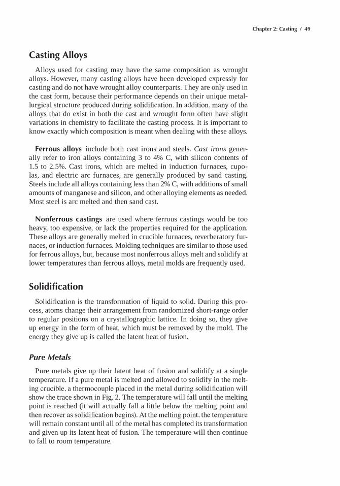
Chapter 2: Casting / 49
Casting Alloys
alloys used for casting may have the same composition as wrought alloys. However, many casting alloys have been developed expressly for casting and do not have wrought alloy counterparts. they are only used in the cast form, because their performance depends on their unique metal-lurgical structure produced during solidification. In addition, many of the alloys that do exist in both the cast and wrought form often have slight variations in chemistry to facilitate the casting process. It is important to know exactly which composition is meant when dealing with these alloys.
Ferrous alloys include both cast irons and steels. Cast irons gener-ally refer to iron alloys containing 3 to 4% c, with silicon contents of 1.5 to 2.5%. cast irons, which are melted in induction furnaces, cupo-las, and electric arc furnaces, are generally produced by sand casting. steels include all alloys containing less than 2% c, with additions of small amounts of manganese and silicon, and other alloying elements as needed. most steel is arc melted and then sand cast.
Nonferrous castings are used where ferrous castings would be too heavy, too expensive, or lack the properties required for the application. these alloys are generally melted in crucible furnaces, reverberatory fur-naces, or induction furnaces. molding techniques are similar to those used for ferrous alloys, but, because most nonferrous alloys melt and solidify at lower temperatures than ferrous alloys, metal molds are frequently used.
Solidification
Solidification is the transformation of liquid to solid. During this pro-cess, atoms change their arrangement from randomized short-range order to regular positions on a crystallographic lattice. In doing so, they give up energy in the form of heat, which must be removed by the mold. the energy they give up is called the latent heat of fusion.
Pure Metals
Pure metals give up their latent heat of fusion and solidify at a single temperature. If a pure metal is melted and allowed to solidify in the melt-ing crucible, a thermocouple placed in the metal during solidification will show the trace shown in Fig. 2. the temperature will fall until the melting point is reached (it will actually fall a little below the melting point and then recover as solidification begins). At the melting point, the temperature will remain constant until all of the metal has completed its transformation and given up its latent heat of fusion. the temperature will then continue to fall to room temperature.
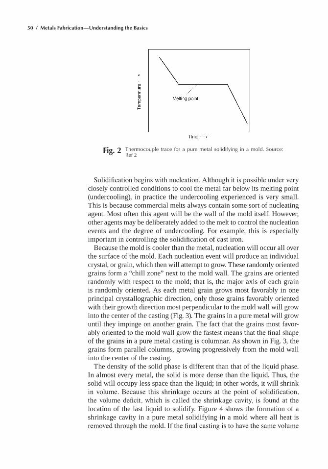
50 / Metals Fabrication—Understanding the Basics
Solidification begins with nucleation. Although it is possible under very closely controlled conditions to cool the metal far below its melting point (undercooling), in practice the undercooling experienced is very small. this is because commercial melts always contain some sort of nucleating agent. most often this agent will be the wall of the mold itself. However, other agents may be deliberately added to the melt to control the nucleation events and the degree of undercooling. For example, this is especially important in controlling the solidification of cast iron.
Because the mold is cooler than the metal, nucleation will occur all over the surface of the mold. each nucleation event will produce an individual crystal, or grain, which then will attempt to grow. these randomly oriented grains form a “chill zone” next to the mold wall. the grains are oriented randomly with respect to the mold; that is, the major axis of each grain is randomly oriented. as each metal grain grows most favorably in one principal crystallographic direction, only those grains favorably oriented with their growth direction most perpendicular to the mold wall will grow into the center of the casting (Fig. 3). the grains in a pure metal will grow until they impinge on another grain. the fact that the grains most favor-ably oriented to the mold wall grow the fastest means that the final shape of the grains in a pure metal casting is columnar. as shown in Fig. 3, the grains form parallel columns, growing progressively from the mold wall into the center of the casting.
the density of the solid phase is different than that of the liquid phase. In almost every metal, the solid is more dense than the liquid. thus, the solid will occupy less space than the liquid; in other words, it will shrink in volume. Because this shrinkage occurs at the point of solidification, the volume deficit, which is called the shrinkage cavity, is found at the location of the last liquid to solidify. Figure 4 shows the formation of a shrinkage cavity in a pure metal solidifying in a mold where all heat is removed through the mold. If the final casting is to have the same volume
Fig. 2 thermocouple trace for a pure metal solidifying in a mold. Source: ref 2
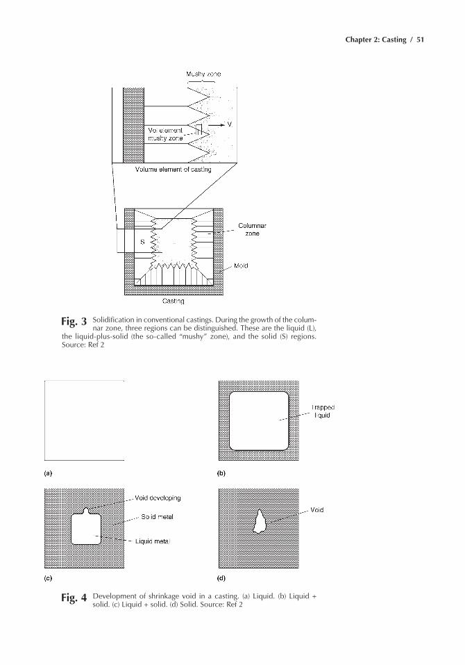
Chapter 2: Casting / 51
Fig. 3 Solidification in conventional castings. During the growth of the colum-nar zone, three regions can be distinguished. these are the liquid (L),
the liquid-plus-solid (the so-called “mushy” zone), and the solid (S) regions. Source: ref 2
Fig. 4 Development of shrinkage void in a casting. (a) Liquid. (b) Liquid + solid. (c) Liquid + solid. (d) Solid. Source: ref 2
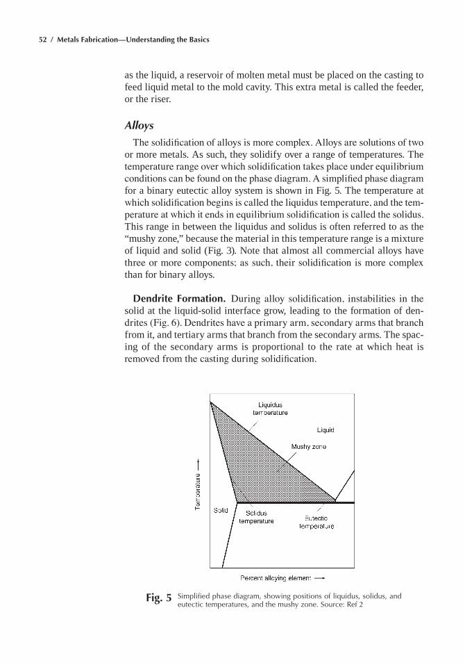
52 / Metals Fabrication—Understanding the Basics
as the liquid, a reservoir of molten metal must be placed on the casting to feed liquid metal to the mold cavity. this extra metal is called the feeder, or the riser.
Alloys
The solidification of alloys is more complex. Alloys are solutions of two or more metals. as such, they solidify over a range of temperatures. the temperature range over which solidification takes place under equilibrium conditions can be found on the phase diagram. A simplified phase diagram for a binary eutectic alloy system is shown in Fig. 5. the temperature at which solidification begins is called the liquidus temperature, and the tem-perature at which it ends in equilibrium solidification is called the solidus. this range in between the liquidus and solidus is often referred to as the “mushy zone,” because the material in this temperature range is a mixture of liquid and solid (Fig. 3). note that almost all commercial alloys have three or more components; as such, their solidification is more complex than for binary alloys.
Dendrite Formation. During alloy solidification, instabilities in the solid at the liquid-solid interface grow, leading to the formation of den-drites (Fig. 6). Dendrites have a primary arm, secondary arms that branch from it, and tertiary arms that branch from the secondary arms. the spac-ing of the secondary arms is proportional to the rate at which heat is removed from the casting during solidification.
Fig. 5 Simplified phase diagram, showing positions of liquidus, solidus, and eutectic temperatures, and the mushy zone. Source: ref 2
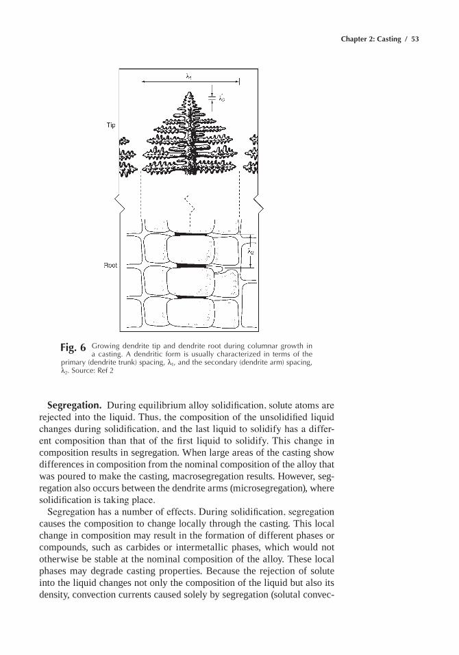
Chapter 2: Casting / 53
Segregation. During equilibrium alloy solidification, solute atoms are rejected into the liquid. Thus, the composition of the unsolidified liquid changes during solidification, and the last liquid to solidify has a differ-ent composition than that of the first liquid to solidify. This change in composition results in segregation. When large areas of the casting show differences in composition from the nominal composition of the alloy that was poured to make the casting, macrosegregation results. However, seg-regation also occurs between the dendrite arms (microsegregation), where solidification is taking place.
Segregation has a number of effects. During solidification, segregation causes the composition to change locally through the casting. this local change in composition may result in the formation of different phases or compounds, such as carbides or intermetallic phases, which would not otherwise be stable at the nominal composition of the alloy. these local phases may degrade casting properties. Because the rejection of solute into the liquid changes not only the composition of the liquid but also its density, convection currents caused solely by segregation (solutal convec-
Fig. 6 Growing dendrite tip and dendrite root during columnar growth in a casting. a dendritic form is usually characterized in terms of the
primary (dendrite trunk) spacing, l1, and the secondary (dendrite arm) spacing, l2. Source: ref 2
54 / Metals Fabrication—Understanding the Basics
tion) may be set up in the casting. the amount of shrinkage that occurs locally will also be a function of the local composition of the liquid when it solidifies. A major effect of segregation is that heat treatment times may be lengthened; that is, the time to homogenize a casting will depend on the dendrite arm spacing (the distance over which solute atoms must travel to go into solution) and the amount of segregation. Because segregation causes the casting composition to vary locally, chemical etching can reveal the cast structure.
When metal is poured into a mold, the liquid has a velocity from the pouring operation. In addition, as the metal cools at the mold wall, thermal convection currents are set up at the mold wall, with the cooling metal traveling downward along the mold wall. these currents, combined with solutal convection and the residual liquid motion from pouring, mean that the liquid in the unsolidified part of the casting is in motion. This movement is usually beneficial, because the motion minimizes macroseg-regation in small castings (although it magnifies it in large castings).
alloys nucleate in the same manner as pure metals. However, during solidification, the liquid motion may break off dendrites and carry them into the liquid. then the dendrites act as nuclei for more grains and mul-tiply the number of grains that nucleate in the liquid. In addition, solute rejection (segregation) may form a region of liquid where the melting point of the liquid rises above the temperature of the melt, meaning that the liquid in that region is now below its melting point. even though the actual temperature of the liquid has not changed, the change in composi-tion resulting from segregation yields an alloy composition locally that has a melting temperature above that of the liquid. this is called constitutional supercooling. The result of these two mechanisms refines the final grain structure of the casting.
Structural Zone Formation. As in pure metals, solidification begins with nucleation of solid on the walls of the mold, again forming a chill zone. then those grains that are most favorably oriented grow inward, forming a columnar zone. However, because of segregation, there is con-stitutional supercooling and grain multiplication. as a result, the last liquid to solidify does so as equiaxed grains. Thus, the final structure of the cast-ing has three zones (Fig. 7). In the equiaxed zone, the grains do not grow progressively from the solid that has already solidified. Instead, they grow simultaneously from their own nuclei, until they impinge on neighboring grains.
The amount of the final cast structure that is columnar or equiaxed depends on the alloy composition and the thermal gradient at the liquid-solid interface during solidification. The thermal gradient is most easily controlled by controlling the rate of heat extraction from the casting, or the cooling rate. alloys that have a wide spread between the liquidus and the solidus temperature solidify with a mostly equiaxed grain structure
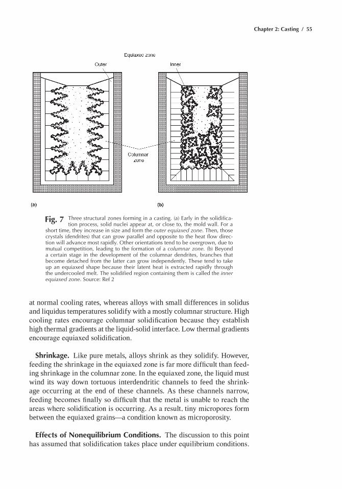
Chapter 2: Casting / 55
at normal cooling rates, whereas alloys with small differences in solidus and liquidus temperatures solidify with a mostly columnar structure. High cooling rates encourage columnar solidification because they establish high thermal gradients at the liquid-solid interface. low thermal gradients encourage equiaxed solidification.
Shrinkage. like pure metals, alloys shrink as they solidify. However, feeding the shrinkage in the equiaxed zone is far more difficult than feed-ing shrinkage in the columnar zone. In the equiaxed zone, the liquid must wind its way down tortuous interdendritic channels to feed the shrink-age occurring at the end of these channels. as these channels narrow, feeding becomes finally so difficult that the metal is unable to reach the areas where solidification is occurring. As a result, tiny micropores form between the equiaxed grains—a condition known as microporosity.
Effects of Nonequilibrium Conditions. the discussion to this point has assumed that solidification takes place under equilibrium conditions.
Fig. 7 three structural zones forming in a casting. (a) early in the solidifica-tion process, solid nuclei appear at, or close to, the mold wall. For a
short time, they increase in size and form the outer equiaxed zone. then, those crystals (dendrites) that can grow parallel and opposite to the heat flow direc-tion will advance most rapidly. Other orientations tend to be overgrown, due to mutual competition, leading to the formation of a columnar zone. (b) Beyond a certain stage in the development of the columnar dendrites, branches that become detached from the latter can grow independently. these tend to take up an equiaxed shape because their latent heat is extracted rapidly through the undercooled melt. the solidified region containing them is called the inner equiaxed zone. Source: ref 2
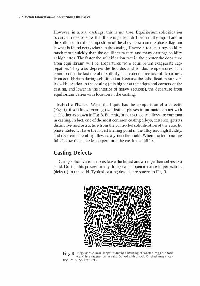
56 / Metals Fabrication—Understanding the Basics
However, in actual castings, this is not true. Equilibrium solidification occurs at rates so slow that there is perfect diffusion in the liquid and in the solid, so that the composition of the alloy shown on the phase diagram is what is found everywhere in the casting. However, real castings solidify much more quickly than the equilibrium rate, and many castings solidify at high rates. The faster the solidification rate is, the greater the departure from equilibrium will be. Departures from equilibrium exaggerate seg-regation. they also depress the liquidus and solidus temperatures. It is common for the last metal to solidify as a eutectic because of departures from equilibrium during solidification. Because the solidification rate var-ies with location in the casting (it is higher at the edges and corners of the casting, and lower in the interior of heavy sections), the departure from equilibrium varies with location in the casting.
Eutectic Phases. When the liquid has the composition of a eutectic (Fig. 5), it solidifies forming two distinct phases in intimate contact with each other as shown in Fig. 8. eutectic, or near-eutectic, alloys are common in casting. In fact, one of the most common casting alloys, cast iron, gets its distinctive microstructure from the controlled solidification of the eutectic phase. Eutectics have the lowest melting point in the alloy and high fluidity, and near-eutectic alloys flow easily into the mold. When the temperature falls below the eutectic temperature, the casting solidifies.
Casting Defects
During solidification, atoms leave the liquid and arrange themselves as a solid. During this process, many things can happen to cause imperfections (defects) in the solid. typical casting defects are shown in Fig. 9.
Fig. 8 Irregular “Chinese script” eutectic consisting of faceted Mg2Sn phase (dark) in a magnesium matrix. etched with glycol. Original magnifica-
tion: 250¥. Source: ref 2
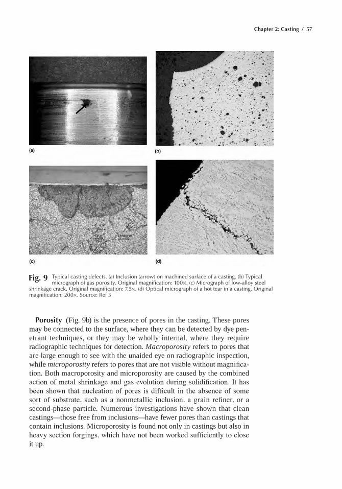
Chapter 2: Casting / 57
Porosity (Fig. 9b) is the presence of pores in the casting. these pores may be connected to the surface, where they can be detected by dye pen-etrant techniques, or they may be wholly internal, where they require radiographic techniques for detection. Macroporosity refers to pores that are large enough to see with the unaided eye on radiographic inspection, while microporosity refers to pores that are not visible without magnifica-tion. Both macroporosity and microporosity are caused by the combined action of metal shrinkage and gas evolution during solidification. It has been shown that nucleation of pores is difficult in the absence of some sort of substrate, such as a nonmetallic inclusion, a grain refiner, or a second-phase particle. numerous investigations have shown that clean castings—those free from inclusions—have fewer pores than castings that contain inclusions. microporosity is found not only in castings but also in heavy section forgings, which have not been worked sufficiently to close it up.
Fig. 9 typical casting defects. (a) Inclusion (arrow) on machined surface of a casting. (b) typical micrograph of gas porosity. Original magnification: 100¥. (c) Micrograph of low-alloy steel
shrinkage crack. Original magnification: 7.5¥. (d) Optical micrograph of a hot tear in a casting. Original magnification: 200¥. Source: ref 3
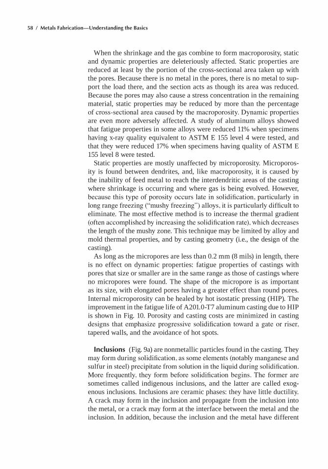
58 / Metals Fabrication—Understanding the Basics
When the shrinkage and the gas combine to form macroporosity, static and dynamic properties are deleteriously affected. static properties are reduced at least by the portion of the cross-sectional area taken up with the pores. Because there is no metal in the pores, there is no metal to sup-port the load there, and the section acts as though its area was reduced. Because the pores may also cause a stress concentration in the remaining material, static properties may be reduced by more than the percentage of cross-sectional area caused by the macroporosity. Dynamic properties are even more adversely affected. a study of aluminum alloys showed that fatigue properties in some alloys were reduced 11% when specimens having x-ray quality equivalent to astm e 155 level 4 were tested, and that they were reduced 17% when specimens having quality of astm e 155 level 8 were tested.
static properties are mostly unaffected by microporosity. microporos-ity is found between dendrites, and, like macroporosity, it is caused by the inability of feed metal to reach the interdendritic areas of the casting where shrinkage is occurring and where gas is being evolved. However, because this type of porosity occurs late in solidification, particularly in long range freezing (“mushy freezing”) alloys, it is particularly difficult to eliminate. the most effective method is to increase the thermal gradient (often accomplished by increasing the solidification rate), which decreases the length of the mushy zone. this technique may be limited by alloy and mold thermal properties, and by casting geometry (i.e., the design of the casting).
as long as the micropores are less than 0.2 mm (8 mils) in length, there is no effect on dynamic properties: fatigue properties of castings with pores that size or smaller are in the same range as those of castings where no micropores were found. the shape of the micropore is as important as its size, with elongated pores having a greater effect than round pores. Internal microporosity can be healed by hot isostatic pressing (HIP). the improvement in the fatigue life of a201.0-t7 aluminum casting due to HIP is shown in Fig. 10. Porosity and casting costs are minimized in casting designs that emphasize progressive solidification toward a gate or riser, tapered walls, and the avoidance of hot spots.
Inclusions (Fig. 9a) are nonmetallic particles found in the casting. they may form during solidification, as some elements (notably manganese and sulfur in steel) precipitate from solution in the liquid during solidification. More frequently, they form before solidification begins. The former are sometimes called indigenous inclusions, and the latter are called exog-enous inclusions. Inclusions are ceramic phases: they have little ductility. a crack may form in the inclusion and propagate from the inclusion into the metal, or a crack may form at the interface between the metal and the inclusion. In addition, because the inclusion and the metal have different
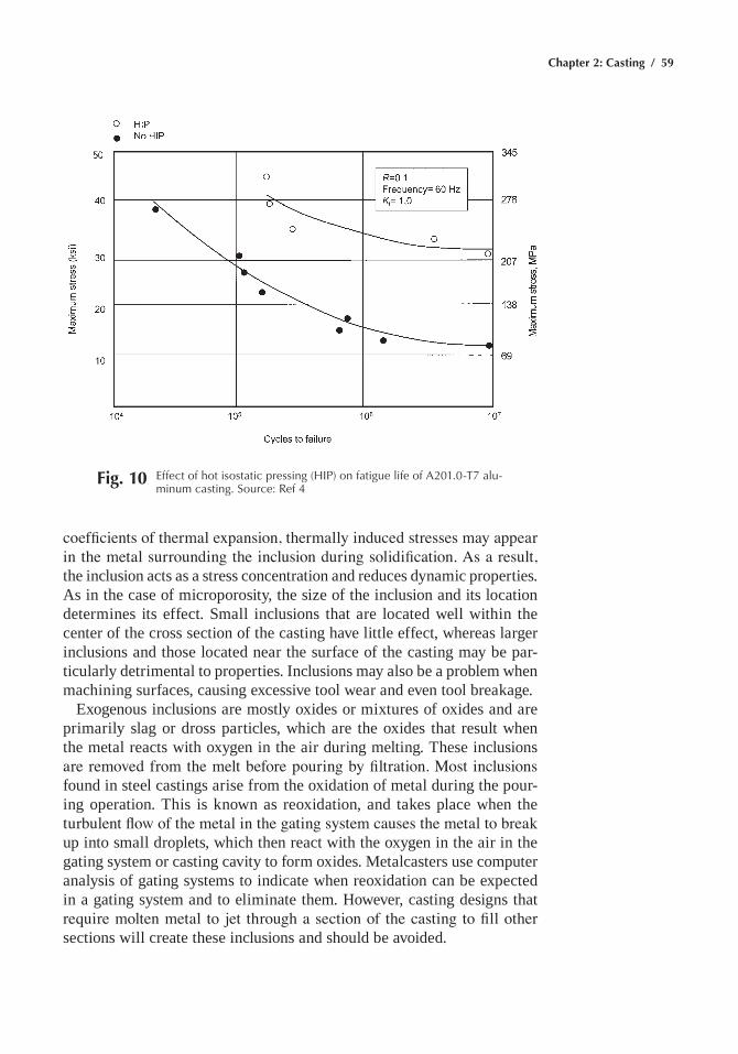
Chapter 2: Casting / 59
coefficients of thermal expansion, thermally induced stresses may appear in the metal surrounding the inclusion during solidification. As a result, the inclusion acts as a stress concentration and reduces dynamic properties. as in the case of microporosity, the size of the inclusion and its location determines its effect. small inclusions that are located well within the center of the cross section of the casting have little effect, whereas larger inclusions and those located near the surface of the casting may be par-ticularly detrimental to properties. Inclusions may also be a problem when machining surfaces, causing excessive tool wear and even tool breakage.
exogenous inclusions are mostly oxides or mixtures of oxides and are primarily slag or dross particles, which are the oxides that result when the metal reacts with oxygen in the air during melting. these inclusions are removed from the melt before pouring by filtration. Most inclusions found in steel castings arise from the oxidation of metal during the pour-ing operation. this is known as reoxidation, and takes place when the turbulent flow of the metal in the gating system causes the metal to break up into small droplets, which then react with the oxygen in the air in the gating system or casting cavity to form oxides. metalcasters use computer analysis of gating systems to indicate when reoxidation can be expected in a gating system and to eliminate them. However, casting designs that require molten metal to jet through a section of the casting to fill other sections will create these inclusions and should be avoided.
Fig. 10 effect of hot isostatic pressing (hIp) on fatigue life of a201.0-t7 alu-minum casting. Source: ref 4
60 / Metals Fabrication—Understanding the Basics
Oxide films are similar to inclusions and have also been found to reduce casting properties. Oxide films form on the surface of the molten metal as it fills the mold. If this surface film is trapped within the casting instead of being carried into a riser, it is a linear discontinuity and an obvious site for crack initiation. It has been shown that elimination of oxide films, in addition to substantially improving static properties, results in a five-fold improvement of fatigue life in axial tension-tension tests.
Oxide films are of particular concern in nonferrous castings, although they must also be controlled in steel and stainless steel castings. Because of their high carbon contents, oxide films do not form in cast irons. If the film is folded over on itself as a result of turbulent flow or “waterfalling” (when molten metal falls to a lower level in the casting during mold filling), the effects are particularly damaging. Casting design influences how the metal fills the mold, and features of the design that require the metal to fall from one level to another while the mold is filling should be avoided so that waterfalls are eliminated. Oxide films are avoided by filling the casting from the bottom in a controlled manner.
Secondary phases that form during solidification may also nucleate cracks if they have the proper size and morphology. an example is alu-minum-silicon alloys, where the silicon is present in the eutectic phase as large platelets, which can nucleate cracks, and along which cracks can propagate. The size of these platelets may be significantly reduced by modifying the alloy with additions of sodium or strontium. However, such additions increase the size of micropores, and for this reason many found-rymen rely on accelerated solidification of the casting to refine the silicon. Solidification rates normally increase and the structure is thus refined in thin sections. If a fine structure is desired, heavy sections are to be avoided. However, in general, secondary phases in the structure of castings become important in limiting mechanical behavior of castings only in the absence of nonmetallic inclusions and microporosity.
Hot tears (Fig. 9d) form when casting sections are constrained by the mold from shrinking as they cool near the end of solidification. These dis-continuities are fairly large and most often weld-repaired. If not repaired, their effect is not readily predictable; while generally they are detrimental to casting properties, under some circumstances they do not affect them. Hot tears are caused by a combination of factors, including alloy type, metal cleanliness, and mold and core hardness. However, poor casting design is the primary cause. castings should be designed so that solidifying sections are not subjected to tensile forces caused by shrinkage during solidifica-tion, because the solidifying alloy has little strength before it solidifies.
Metal Penetration. molten metal may penetrate the surface of the mold forming a rough surface, or in extreme cases, it may actually become inti-
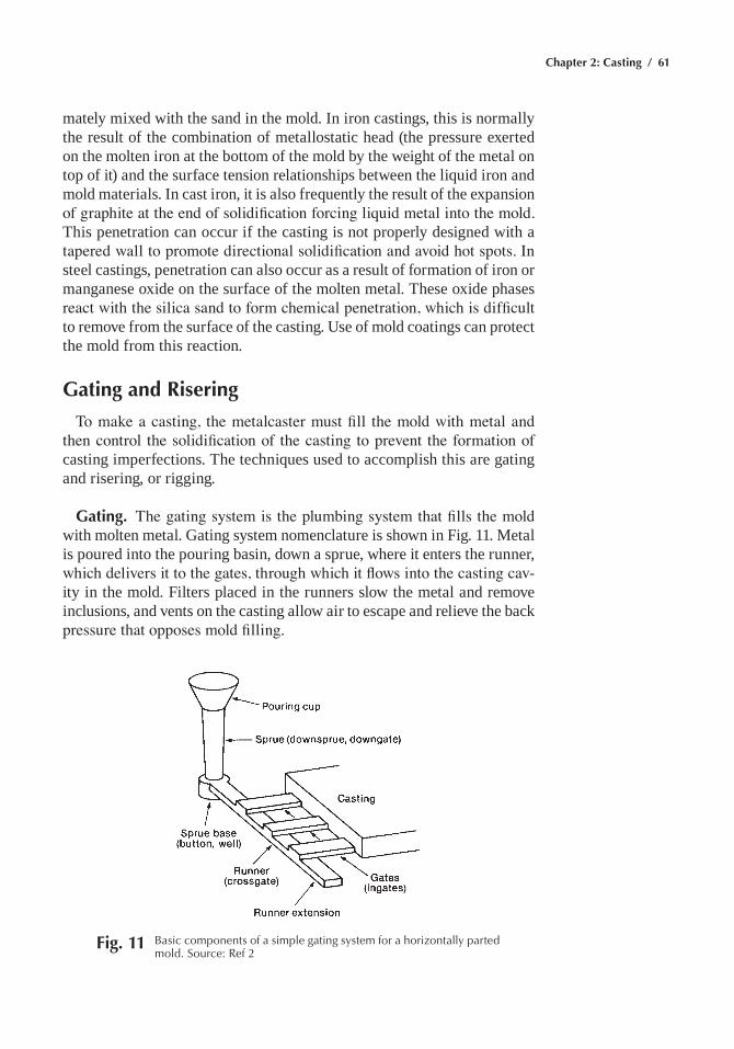
Chapter 2: Casting / 61
mately mixed with the sand in the mold. In iron castings, this is normally the result of the combination of metallostatic head (the pressure exerted on the molten iron at the bottom of the mold by the weight of the metal on top of it) and the surface tension relationships between the liquid iron and mold materials. In cast iron, it is also frequently the result of the expansion of graphite at the end of solidification forcing liquid metal into the mold. this penetration can occur if the casting is not properly designed with a tapered wall to promote directional solidification and avoid hot spots. In steel castings, penetration can also occur as a result of formation of iron or manganese oxide on the surface of the molten metal. these oxide phases react with the silica sand to form chemical penetration, which is difficult to remove from the surface of the casting. Use of mold coatings can protect the mold from this reaction.
Gating and Risering
To make a casting, the metalcaster must fill the mold with metal and then control the solidification of the casting to prevent the formation of casting imperfections. the techniques used to accomplish this are gating and risering, or rigging.
Gating. The gating system is the plumbing system that fills the mold with molten metal. gating system nomenclature is shown in Fig. 11. metal is poured into the pouring basin, down a sprue, where it enters the runner, which delivers it to the gates, through which it flows into the casting cav-ity in the mold. Filters placed in the runners slow the metal and remove inclusions, and vents on the casting allow air to escape and relieve the back pressure that opposes mold filling.
Fig. 11 Basic components of a simple gating system for a horizontally parted mold. Source: ref 2
62 / Metals Fabrication—Understanding the Basics
The gating system must fill the mold quickly, while minimizing turbu-lence. turbulence causes the molten metal to mix with air in the sprue and runners. the oxygen in the air reacts with the molten metal, forming oxide inclusions. Unfortunately, it is difficult to minimize turbulence in gating systems in medium-size and large castings, because the velocity the metal reaches on falling down the sprue is usually so great that turbulence is unavoidable. Ceramic filters slow the velocity of the metal in the run-ner, which fills the sprue with metal. Good gating practice recommends that the system be unpressurized, that is, the cross-sectional area of the downsprue should be less than the total cross-sectional area of the run-ners, which, in turn, should be less than the total cross-sectional area of the gates. Runner cross sections are usually rectangular, so that metal does not swirl down the runners and entrap air. Runners should be free from sharp edges, and gates should be filleted.
the gating system should establish thermal gradients to promote a sound porosity-free casting. the ideal situation is to have the casting freeze from thin sections (which freeze quickly) to thick sections, so that feed metal is available to feed shrinkage as it occurs. As molten metal flows through the gating system, it loses heat to the runners and heats them up. thus, the first metal into the mold is coldest, and the last metal is hottest. For this reason, gates should be placed into heavy sections of the casting, so that hot metal is available to feed shrinkage that occurs in the casting as the casting solidifies. By having solidification take place progressively toward the gates and risers, shrinkage porosity is avoided.
good gating systems should avoid reoxidation of the metal, avoid the formation of oxide folds, and, if possible, remove oxide and dross from the molten metal. gating systems should be designed to prevent the aspiration of air through the porous molding media. the position of the casting in the mold should be given careful thought. normally the casting should have its longest dimension parallel to the parting plane. metal should not drop from one level in the casting cavity to a lower level because the oxide film that forms on the top of the molten metal mixes into the metal in the casting, which causes inclusions.
Filters strain out most of the slag or dross that may have been carried in from the melting operation, and pieces of mold refractory that may have come loose during molding. metal should not rain down from the top of the sprue or into the casting because it will react with the air in the runner system or the casting cavity. Therefore, filters should not be placed at the top of the sprue, and gates should be placed at the bottom of the mold, so that the casting cavity fills from the bottom.
Risering. Riser design deals with the sizing and placement of reser-voirs of feed metal to compensate for the shrinkage that occurs during solidification. These reservoirs are called risers or feeders. When liquid
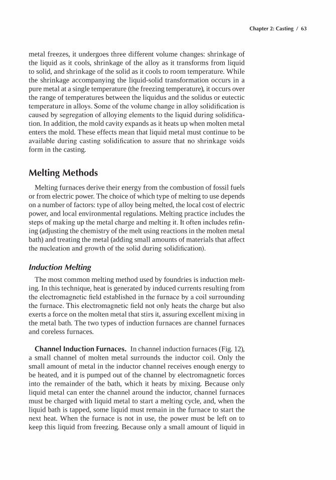
Chapter 2: Casting / 63
metal freezes, it undergoes three different volume changes: shrinkage of the liquid as it cools, shrinkage of the alloy as it transforms from liquid to solid, and shrinkage of the solid as it cools to room temperature. While the shrinkage accompanying the liquid-solid transformation occurs in a pure metal at a single temperature (the freezing temperature), it occurs over the range of temperatures between the liquidus and the solidus or eutectic temperature in alloys. Some of the volume change in alloy solidification is caused by segregation of alloying elements to the liquid during solidifica-tion. In addition, the mold cavity expands as it heats up when molten metal enters the mold. these effects mean that liquid metal must continue to be available during casting solidification to assure that no shrinkage voids form in the casting.
Melting Methods
melting furnaces derive their energy from the combustion of fossil fuels or from electric power. the choice of which type of melting to use depends on a number of factors: type of alloy being melted, the local cost of electric power, and local environmental regulations. melting practice includes the steps of making up the metal charge and melting it. It often includes refin-ing (adjusting the chemistry of the melt using reactions in the molten metal bath) and treating the metal (adding small amounts of materials that affect the nucleation and growth of the solid during solidification).
Induction Melting
the most common melting method used by foundries is induction melt-ing. In this technique, heat is generated by induced currents resulting from the electromagnetic field established in the furnace by a coil surrounding the furnace. This electromagnetic field not only heats the charge but also exerts a force on the molten metal that stirs it, assuring excellent mixing in the metal bath. the two types of induction furnaces are channel furnaces and coreless furnaces.
Channel Induction Furnaces. In channel induction furnaces (Fig. 12), a small channel of molten metal surrounds the inductor coil. Only the small amount of metal in the inductor channel receives enough energy to be heated, and it is pumped out of the channel by electromagnetic forces into the remainder of the bath, which it heats by mixing. Because only liquid metal can enter the channel around the inductor, channel furnaces must be charged with liquid metal to start a melting cycle, and, when the liquid bath is tapped, some liquid must remain in the furnace to start the next heat. When the furnace is not in use, the power must be left on to keep this liquid from freezing. Because only a small amount of liquid in
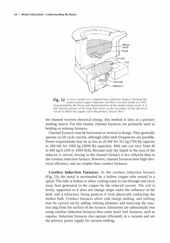
64 / Metals Fabrication—Understanding the Basics
the channel receives electrical energy, this method is slow as a primary melting source. For this reason, channel furnaces are primarily used as holding or refining furnaces.
channel furnaces may be horizontal or vertical in design. they generally operate on 60 cycle current, although other melt frequencies are possible. Power requirements may be as low as 20 kW for 315 kg (700 lb) capacity to 200 kW for 1360 kg (3000 lb) capacities. melt rate can vary from 45 to 450 kg/h (100 to 1000 lb/h). Because only the liquid in the area of the inductor is stirred, mixing in the channel furnace is less efficient than in the coreless induction furnace. However, channel furnaces have high elec-trical efficiency and are simpler than coreless furnaces.
Coreless Induction Furnaces. In the coreless induction furnace (Fig. 13), the metal is surrounded by a hollow copper tube wound in a spiral. the tube is hollow to allow cooling water to run through and carry away heat generated in the copper by the induced current. the coil is firmly supported so it does not change shape under the influence of the field, and a refractory lining protects it from physically contacting the molten bath. Coreless furnaces allow cold charge melting, and refining may be carried out by adding refining elements and removing the reac-tion slag from the surface of the furnace. emissions are substantially less using coreless induction furnaces than some fossil fuel furnaces, such as cupolas. Induction furnaces also operate efficiently in a vacuum and are the primary power supply for vacuum melting.
Fig. 12 a cross section of a channel-type induction furnace showing the water-cooled copper induction coil that is located inside of a 360°
loop formed by the throat and channel portion of the molten metal vessel. It is the channel portion of the loop that serves as the secondary of the electrical circuit in which the copper coil is the primary. Source: ref 5
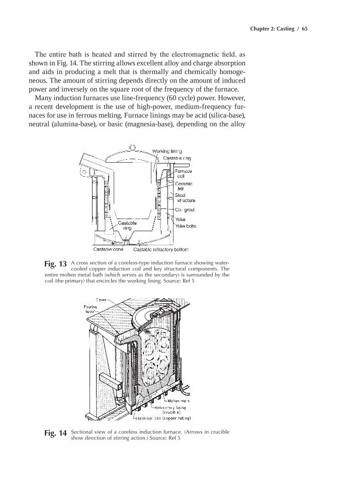
Chapter 2: Casting / 65
The entire bath is heated and stirred by the electromagnetic field, as shown in Fig. 14. the stirring allows excellent alloy and charge absorption and aids in producing a melt that is thermally and chemically homoge-neous. the amount of stirring depends directly on the amount of induced power and inversely on the square root of the frequency of the furnace.
many induction furnaces use line-frequency (60 cycle) power. However, a recent development is the use of high-power, medium-frequency fur-naces for use in ferrous melting. Furnace linings may be acid (silica-base), neutral (alumina-base), or basic (magnesia-base), depending on the alloy
Fig. 13 a cross section of a coreless-type induction furnace showing water-cooled copper induction coil and key structural components. the
entire molten metal bath (which serves as the secondary) is surrounded by the coil (the primary) that encircles the working lining. Source: ref 5
Fig. 14 Sectional view of a coreless induction furnace. (arrows in crucible show direction of stirring action.) Source: ref 5
66 / Metals Fabrication—Understanding the Basics
being melted. silica is usually used for ferrous heats because it does not extensively react with the acid slag produced by the high silicon-contain-ing iron compositions. It is inexpensive, and its thermal expansion is flat above 815 °c (1500 °F). alumina is generally used with aluminum alloys, and magnesia linings are used with steel compositions that require a basic refractory to maintain proper composition. alumina and magnesia have less thermal shock resistance than silica.
Induction furnaces may be operated either in a batch mode, in which the entire charge is emptied and a new charge is melted, or a tap-and-charge mode, in which only a portion (typically one-third) of the melt is emptied, and new charge materials are added to the remaining charge and melted in. The batch operation has a somewhat higher melting efficiency, but chemis-try is easier to control in tap-and-charge operation, because only one-third of the furnace charge must be added. In foundry melting, the charge usu-ally consists primarily of scrap and foundry returns (gates, risers, and scrapped castings). chemistry is adjusted by adding the elements needed to reach the proper composition. scrap must be preheated before charging to burn off machining oil, which can contaminate the charge and drive off all moisture, adding unwanted hydrogen to the bath, and, if enough water is present, causing a steam explosion when charged into the furnace.
Cupola Melting
cupolas are vertical shaft furnaces used for melting cast iron. although similar in principle to blast furnaces, they are not miniature blast furnaces. In operation, coke, flux, and metal are charged into the top of the furnace, and air, often preheated and/or enriched with oxygen, is blown in at the bottom through tuyeres. the coke burns in the air, melting the metal that trickles down to the bottom of the furnace or well, where it is tapped. sectional views of cupolas are shown in Fig. 15.
Cupolas are highly energy-efficient melting furnaces for cast iron. How-ever, they produce large quantities of particulate and exhaust gases. these emission products must be removed from the gases discharged into the atmosphere, and the equipment required to accomplish this is expensive to purchase and operate. as a result, cupolas, despite their inherent sim-plicity and energy efficiency, are only used by the largest foundries, which require a high tonnage of molten iron in daily operation. the advantages of using cupolas in high-tonnage foundries include the fact that molten metal delivery is continuous, uninterrupted by the need to charge or melt new material. as requirements on cast iron tighten, the cupola is used more and more as a bulk melter to provide metal for subsequent refin-ing and treatment operations, usually carried out in induction furnaces or special treatment ladles, and less as a method of providing iron ready to be poured into molds. However, as a bulk melter, it is unsurpassed when large quantities of consistent-quality iron are required. the concentra-tion of cupola melting in high-tonnage applications has resulted in the
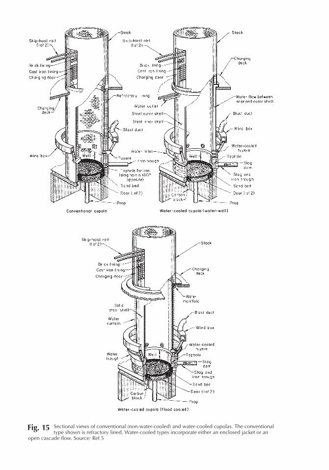
Fig. 15 Sectional views of conventional (non-water-cooled) and water-cooled cupolas. the conventional type shown is refractory lined. Water-cooled types incorporate either an enclosed jacket or an
open cascade flow. Source: ref 5
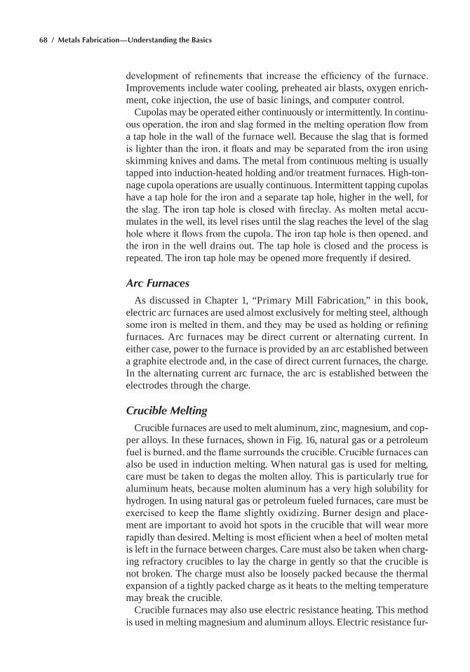
68 / Metals Fabrication—Understanding the Basics
development of refinements that increase the efficiency of the furnace. Improvements include water cooling, preheated air blasts, oxygen enrich-ment, coke injection, the use of basic linings, and computer control.
cupolas may be operated either continuously or intermittently. In continu-ous operation, the iron and slag formed in the melting operation flow from a tap hole in the wall of the furnace well. Because the slag that is formed is lighter than the iron, it floats and may be separated from the iron using skimming knives and dams. the metal from continuous melting is usually tapped into induction-heated holding and/or treatment furnaces. High-ton-nage cupola operations are usually continuous. Intermittent tapping cupolas have a tap hole for the iron and a separate tap hole, higher in the well, for the slag. The iron tap hole is closed with fireclay. As molten metal accu-mulates in the well, its level rises until the slag reaches the level of the slag hole where it flows from the cupola. The iron tap hole is then opened, and the iron in the well drains out. the tap hole is closed and the process is repeated. the iron tap hole may be opened more frequently if desired.
Arc Furnaces
as discussed in chapter 1, “Primary mill Fabrication,” in this book, electric arc furnaces are used almost exclusively for melting steel, although some iron is melted in them, and they may be used as holding or refining furnaces. arc furnaces may be direct current or alternating current. In either case, power to the furnace is provided by an arc established between a graphite electrode and, in the case of direct current furnaces, the charge. In the alternating current arc furnace, the arc is established between the electrodes through the charge.
Crucible Melting
crucible furnaces are used to melt aluminum, zinc, magnesium, and cop-per alloys. In these furnaces, shown in Fig. 16, natural gas or a petroleum fuel is burned, and the flame surrounds the crucible. Crucible furnaces can also be used in induction melting. When natural gas is used for melting, care must be taken to degas the molten alloy. this is particularly true for aluminum heats, because molten aluminum has a very high solubility for hydrogen. In using natural gas or petroleum fueled furnaces, care must be exercised to keep the flame slightly oxidizing. Burner design and place-ment are important to avoid hot spots in the crucible that will wear more rapidly than desired. Melting is most efficient when a heel of molten metal is left in the furnace between charges. care must also be taken when charg-ing refractory crucibles to lay the charge in gently so that the crucible is not broken. the charge must also be loosely packed because the thermal expansion of a tightly packed charge as it heats to the melting temperature may break the crucible.
crucible furnaces may also use electric resistance heating. this method is used in melting magnesium and aluminum alloys. electric resistance fur-
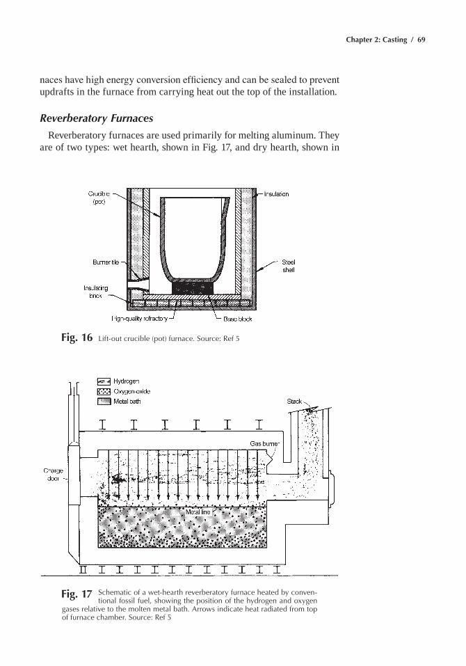
Chapter 2: Casting / 69
Fig. 17 Schematic of a wet-hearth reverberatory furnace heated by conven-tional fossil fuel, showing the position of the hydrogen and oxygen
gases relative to the molten metal bath. arrows indicate heat radiated from top of furnace chamber. Source: ref 5
naces have high energy conversion efficiency and can be sealed to prevent updrafts in the furnace from carrying heat out the top of the installation.
Reverberatory Furnaces
Reverberatory furnaces are used primarily for melting aluminum. they are of two types: wet hearth, shown in Fig. 17, and dry hearth, shown in
Fig. 16 Lift-out crucible (pot) furnace. Source: ref 5
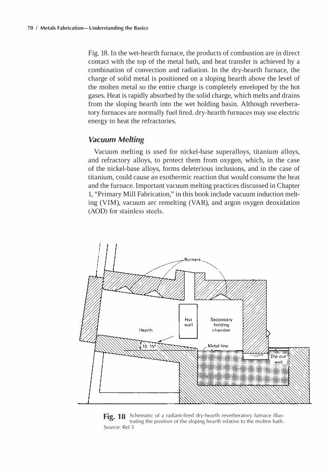
70 / Metals Fabrication—Understanding the Basics
Fig. 18 Schematic of a radiant-fired dry-hearth reverberatory furnace illus-trating the position of the sloping hearth relative to the molten bath.
Source: ref 5
Fig. 18. In the wet-hearth furnace, the products of combustion are in direct contact with the top of the metal bath, and heat transfer is achieved by a combination of convection and radiation. In the dry-hearth furnace, the charge of solid metal is positioned on a sloping hearth above the level of the molten metal so the entire charge is completely enveloped by the hot gases. Heat is rapidly absorbed by the solid charge, which melts and drains from the sloping hearth into the wet holding basin. although reverbera-tory furnaces are normally fuel fired, dry-hearth furnaces may use electric energy to heat the refractories.
Vacuum Melting
Vacuum melting is used for nickel-base superalloys, titanium alloys, and refractory alloys, to protect them from oxygen, which, in the case of the nickel-base alloys, forms deleterious inclusions, and in the case of titanium, could cause an exothermic reaction that would consume the heat and the furnace. Important vacuum melting practices discussed in chapter 1, “Primary mill Fabrication,” in this book include vacuum induction melt-ing (VIm), vacuum arc remelting (VaR), and argon oxygen deoxidation (AOD) for stainless steels.
Chapter 2: Casting / 71
Casting Methods
casting methods and materials encompass a wide range of options. some casting processes are centuries old, while others did not exist two generations ago. The selection of the correct one to use in a specific casting application depends on the alloy, the dimensional tolerances desired, the quality of the casting, and the price the customer is willing to pay. most metals and alloys can be cast using any of the methods. there are, however, limitations in some cases.
Foundry processes can be classified based on the molding medium, such as sand molds, ceramic molds, and metallic molds. molding methods may also be classified based on whether the molds are permanent or expend-able. Similarly, subclassifications can be developed from patterns, (i.e., whether or not the patterns are expendable). For permanent molding, pro-cesses can be classified by the type of mechanism used to fill the mold. One possible classification system for commonly employed molding and casting processes is shown in table 1.
Of the expendable mold/permanent pattern processes listed in table 1, green sand molding is the most prevalent. expendable mold/expendable pattern processes use wax patterns (investment casting) or foamed plas-tic patterns (lost foam casting). the investment casting process is one of the oldest casting processes known (it has been used for more than 6000 years), while the lost foam process has been used commercially for less than 30 years. Permanent mold processes involve the use of metallic (usu-ally ferrous) or solid graphite molds. On a volume basis, die casting and permanent mold casting are the most important.
Sand Casting
sand casting is the oldest known casting process. the molten metal is poured into a cavity shaped inside a body of sand and allowed to solidify. Advantages of sand casting are low equipment costs, design flexibility, ability to cast complex geometries, producibility for large castings, appli-cability to a large number of casting alloys, and it is economical for low quantities. the biggest disadvantages are that the process does not per-mit close tolerances, it produces rather rough surface finishes, it requires relatively thick walls for the cast parts (~3 mm, or 0.12 in.), it produces somewhat lower mechanical properties due to larger grain sizes (resulting from slow cooling rates), and it has rather high labor costs per part. the steps involved in sand casting are shown in Fig. 19 and consist of:
1. Fabricate a pattern, usually wood, of the desired part and split it down the centerline.
2. Place the bottom half of the pattern, called the drag, in a box called a flask.
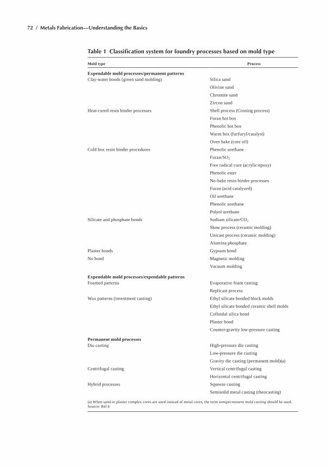
72 / Metals Fabrication—Understanding the Basics
Table 1 Classification system for foundry processes based on mold type
Mold type Process
Expendable mold processes/permanent patternsclay-water bonds (green sand molding) silica sand
Olivine sand
chromite sand
Zircon sand
Heat-cured resin binder processes shell process (croning process)
Furan hot box
Phenolic hot box
Warm box (furfuryl/catalyst)
Oven bake (core oil)
cold box resin binder procedures Phenolic urethane
Furan/sO2
Free radical cure (acrylic/epoxy)
Phenolic ester
no-bake resin binder processes
Furan (acid catalyzed)
Oil urethane
Phenolic urethane
Polyol urethane
silicate and phosphate bonds sodium silicate/cO2
shaw process (ceramic molding)
Unicast process (ceramic molding)
alumina phosphate
Plaster bonds gypsum bond
no bond magnetic molding
Vacuum molding
Expendable mold processes/expendable patternsFoamed patterns evaporative foam casting
Replicast process
Wax patterns (investment casting) ethyl silicate bonded block molds
ethyl silicate bonded ceramic shell molds
colloidal silica bond
Plaster bond
counter-gravity low-pressure casting
Permanent mold processesDie casting High-pressure die casting
low-pressure die casting
gravity die casting (permanent mold)(a)
centrifugal casting Vertical centrifugal casting
Horizontal centrifugal casting
Hybrid processes squeeze casting
semisolid metal casting (rheocasting)
(a) When sand or plaster complex cores are used instead of metal cores, the term semipermanent mold casting should be used. source: Ref 6
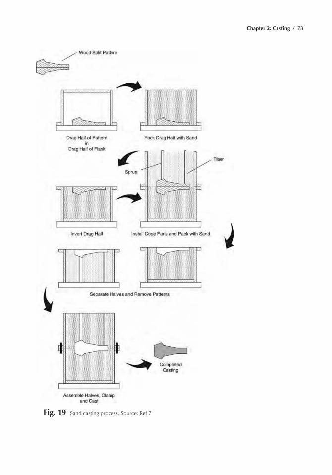
Chapter 2: Casting / 73
Fig. 19 Sand casting process. Source: ref 7
74 / Metals Fabrication—Understanding the Basics
3. Apply a release coating to the pattern, fill the flask with sand, and then compact the sand by ramming.
4. Turn the drag half of the mold over and place the top half of the flask on top of it. the top half of the pattern, called the cope, is then placed over the drag half of the pattern and release coated.
5. Risers and a sprue are then installed in the cope half of the flask. The sprue is where liquid metal enters the mold. In a complex casting, the sprue is usually gated to different positions around the casting. the risers are essentially reservoirs for liquid metal that keep the cast-ing supplied with liquid metal as the metal shrinks and contracts on freezing.
6. the cope half is then packed with sand and rammed.7. the two halves are separated and the patterns are removed. If hollow
sections are required, sand cores are placed in the drag half of the mold. a gating system is then cut into the sand on the cope half of the mold.
8. the two halves are reassembled and clamped or bolted shut for casting.
silica sand, either bonded or unbonded, is the most popular molding media. sand has the advantage of being widely available, inexpensive, able to withstand the elevated temperatures in casting most alloys, and easily recycled. In addition, it does not react with most metals and alloys, and it can be bonded with clay, resins, or silicate compounds. Because sand molds are permeable, the air displaced by the metal when it enters the mold can escape through the mold.
Bonded Sand Molds
In bonded sand molds, the sand particles are held together with chemi-cal bonds. the bonds that are developed must be easily broken when the casting is solid so that the casting can be removed from the mold.
Green sand molds are made of sand bonded with a mixture of clay and water. Other materials may be added to the sand to control its strength and prevent metal penetration. the term green means that the mold contains some moisture at the time of pouring; however, its actual color is black. the sand is not baked or fired. Green sand molds possess sufficient strength for most applications, good collapsibility, good permeability, good reusability, and are the least expensive of the molds. they are the most widely used mold type; however, they are not without problems. moisture in the sand can cause defects in some castings, depending on the metal and geometry of the part. green sand molds are the most widely used of all sand molds.
the aggregate usually used in green sand casting is silica sand, usually from former lake bottoms or riverbank deposits. sand is usually 99% silica in the form of quartz, with the balance being oxides of iron, aluminum,

Chapter 2: Casting / 75
titanium, magnesium, and calcium, depending on the source of the sand. sand grains may be rounded, subangular, or angular in shape. Rounded grains flow more easily and pack more densely. They also use less binder because their surface-area-to-volume ratio is smaller than other shapes. However, molds made from them have less permeability. as sand is cycled through the system, it wears and eventually becomes too small to be used and must be discarded.
sand used for molding is usually held within strict size and size distri-bution limits. the sand size is determined by passing a sample of sand through a series of successively finer screens and weighing the amount collected on each screen. the best combination of properties of green sand is usually found when almost all of the sand is caught on three or four adjacent screens; however, two screen sands have been used successfully for certain casting processes.
the sand is bonded by a clay-water mixture. clays used in the United states are naturally occurring montmorillonites, sodium (Western) ben-tonite and calcium (southern) bentonite. Western bentonite is the most commonly used clay. It develops a lower green strength than southern ben-tonite but has higher strength at casting temperatures. However, southern bentonites allow the sand mixture to flow more evenly over the pattern and thus aid the molding operation. Usually, a foundry will prepare a mix of both southern and Western bentonites to achieve a sand that is optimized for the castings it makes. the sand, water, and clay are mixed in a muller for a period of one to two minutes; during this time the clay-water mixture coats the sand.
Other materials are added to the sand to improve its performance. chief among these materials for ferrous alloys is seacoal, which is powdered bituminous coal. When heated, seacoal cokes plastically expand and fill the interstices between the sand grains at the casting surface, thus pre-venting penetration of molten metal into the sand. In addition, it burns, assuring that the atmosphere at the mold-metal interface is reducing, so that fayalite (a low-melting-point solution of iron oxide and silica) does not form on steel castings. cellulose may be added in amounts up to 0.2% to absorb excess water and control sand expansion. Polymers may be added to control the surface energy of water so that it coats the sand grains more effectively, and soda ash may be added in very small amounts to control the pH of the sand mixture.
the casting cavity is formed in the sand mold by compressing it around a pattern, which is a wooden, plastic, or metal form that has the shape of the casting, together with its gates, risers, and core prints (Fig. 20). In bonded sand processes, the pattern is removed from the mold and used repetitively to make molds. the dimensions of the pattern are slightly greater than that of the castings because the casting shrinks during solidification. Castings distort as they cool, as a result of stresses produced by the resistance of the mold to casting shrinkage, so patterns must be designed to compensate for
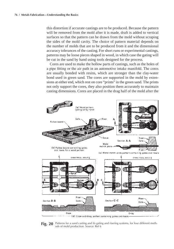
76 / Metals Fabrication—Understanding the Basics
this distortion if accurate castings are to be produced. Because the pattern will be removed from the mold after it is made, draft is added to vertical surfaces so that the pattern can be drawn from the mold without scraping the sides of the mold cavity. the choice of pattern material depends on the number of molds that are to be produced from it and the dimensional accuracy tolerances of the casting. For short runs or experimental castings, patterns may be loose pieces shaped in wood, in which case the gating will be cut in the sand by hand using tools designed for the process.
cores are used to make the hollow parts of castings, such as the holes of a pipe fitting or the air path in an automotive intake manifold. The cores are usually bonded with resins, which are stronger than the clay-water bond used in green sand. the cores are supported in the mold by exten-sions at either end, which rest on core “prints” in the green sand. the prints not only support the cores, they also position them accurately to maintain casting dimensions. cores are placed in the drag half of the mold after the
Fig. 20 patterns for a sand casting and its gating and risering systems, for four different meth-ods of mold production. Source: ref 6
Chapter 2: Casting / 77
pattern is drawn from the mold and before the cope is placed on the drag to close the mold.
match-plate patterns (Fig. 20c) are split patterns in which the pattern that will make the cope is on one side of the plate, and the pattern that will make the drag is on the other side. match-plate patterns are used on mechanized molding machines for intermediate runs of moderate-sized castings. more than one casting may be made in a mold, with the sprue, gates, and risers shared among the castings. In match-plate machine mold-ing, the sand is introduced into the molding box, and the pattern is placed on a machine table. the machine then raises the table a few inches and then lets it fall back freely by gravity. the sharp jolt experienced by the sand when the machine table stops falling compresses the sand in the box. the procedure is repeated a number of times until the sand is properly compressed. Usually the mold is then subjected to a squeeze pressure from the top to further compress the sand.
For large castings and very high production runs, cope and drag patterns (Fig. 20d) are used on highly automated molding machines. the cope pat-tern is separate from the drag pattern, and separate molding stations are used to make each mold half. cores may be placed in the molds by hand or by using automated fixtures. In some machines, only squeezing is used to compact the sand; in others, both jolting and squeezing is used. Parting lines may be either horizontal or vertical.
Impact molding machines use rapidly released compressed air above the sand in the pattern box to send a shock wave through the sand to compress it. The flask is filled with sand by gravity and sealed against an air chamber before the compressed air is released. advantages of the impact molding process are highest mold density at the parting line and pattern surface, uniform mold strength across the mold, and less pattern wear than with other processes.
When molten metal is poured into a green sand mold, the moisture at the mold-metal interface flashes into steam. This rapid expansion in volume (liquid transforming into vapor) flushes the air away from the interface. the air and the expanding water vapor must escape from the mold. In high-density molding processes, such as impact molding, the permeability of the mold is not sufficient, and vents must be cut into the mold to prevent the back pressure from the gases from blocking the entrance of the molten metal and causing the casting to only partially fill with metal.
Dry Sand Molds
Dry sand molding is sometimes used to make large castings, although resin-bonded molds have largely replaced this process. In dry sand mold-ing, the water is removed from the mold prior to pouring. the bond is created both by using bentonite clays and also through the use of other organic binders, such as dextrin, molasses, glutrin, or pitch. the molds
78 / Metals Fabrication—Understanding the Basics
are baked in ovens prior to pouring to drive out the moisture. Baking temperature and time depend on the size of the mold and the binder used. Dry sand molds are generally stronger than green sand and usually have better dimensional stability than green sand in larger castings. the sand grain size is usually coarser in dry sand molding to allow the increased permeability of the mold to aid in mold drying. therefore, mold washes and coatings are often applied to improve surface finish. As an alternative to drying the entire mold, only the surface of the casting cavity may be dried. these “skin-dried molds” are made from the same sand mixtures as dry sand molds, but only the surface that will contact the molten metal is dried to a depth of 6 to 12 mm (0.25 to 0.5 in.).
Resin-Bonded Sand Molds
Over the last thirty years, a number of resins have been developed as binders for sand, primarily for making cores, although they are also used as molds. In these processes, sand and binder are mixed together and formed around a pattern or placed in a core box. the resin may be cured by heat, or it may be cured by the setting of the resin. to accelerate the curing of the resin, catalysts may be added, either in solid, liquid, or gaseous form.
the term no-bake generally refers to all of the binder systems in which a gas catalyzes the resin while the sand is in contact with the core box or pattern. Originally it only referred to the phenolic-urethane-amine process, which is still the most popular core resin in use. In addition to the phenolic-urethane-amine process, other no-bake binder systems include furan acid catalyzed, phenolic acid catalyzed, ester-cured, and alkyd-urethane bind-ers. Furan binders depend on the use of furfuryl alcohol, either by itself or modified with urea, phenol, formaldehyde, or other additions. The binders cure at room temperature by the addition of an acid catalyst and have reac-tion products, such as nitrogen gas and water. the amount of binder used must usually be minimized, both for economic reasons and to limit the amount of nitrogen gas picked up in ferrous castings, where it can cause pinholes, and water vapor picked up in nonferrous castings, where it causes microporosity. the catalyst used depends on the rate of cure required and the type of metal cast.
Shell Molding
shell molding can also be used in place of sand casting when a bet-ter surface finish or tighter dimensional control is required. Because it requires precision metal patterns and more specialized equipment, shell molding should be considered a higher-volume process than sand casting. shell molding, shown in Fig. 21, consists of:
1. A fine silica sand mixed with a phenolic resin is placed in a dump box that can be rotated.
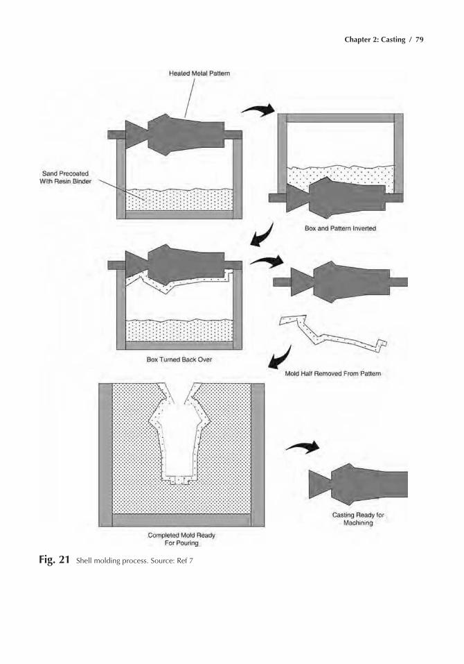
Chapter 2: Casting / 79
Fig. 21 Shell molding process. Source: ref 7
80 / Metals Fabrication—Understanding the Basics
2. a metal pattern is heated to 205 to 260 °c (400 to 500 °F), mold released, and placed in the dump box.
3. the pattern and sand are inverted, allowing the sand to coat the heated pattern. a crust of sand fuses around the part as a result of the heat.
4. the dump box is turned right side up, and the pattern with the shell crust is removed and cured in an oven at 345 to 400 °c (650 to 750 °F).
5. the same process is repeated for the other half of the mold.6. The two mold halves are clamped together and placed in a flask sup-
ported with either sand or metal shot.
Plaster Casting
Plaster mold casting is basically the same as sand casting except that gypsum plasters are used instead of sand. the advantages are very smooth surfaces, good dimensional tolerances, and microstructural uniformity due to slow uniform cooling. However, as a result of the slow solidification rates (therefore, larger grain sizes), the mechanical properties are not as good as with sand castings. In addition, because plaster can absorb sig-nificant moisture from the atmosphere, the mold may require slow drying prior to casting. the plaster casting process is used to produce near-net shape castings such as impellers, tire molds, matchplate patterns for found-ries, and electronic equipment housings.
In the conventional plaster mold process, the principal mold ingredient is calcium sulfate. Other materials may be used to enhance mold properties, such as green strength and permeability. these materials include cement, talc, fiberglass, sand, clay, and other materials. Calcium sulfate exists as two different hydrates and in an anhydrous form. Its dihydrate is known as gypsum (casO42H2O). above 130 °c (260 °F), gypsum loses three-fourths of its water to become plaster of paris, which loses the rest of its water at 165 °c (325 °F) to become calcium sulfate.
to produce a plaster mold, plaster of paris is mixed with water to form a slurry, which is immediately poured over a pattern or into a core box, where it sets, forming a solid mold or core of gypsum with free water dis-tributed in the mold. the pattern is normally coated with a release agent before the slurry is poured. mechanical vibration may be used to eliminate pinholes in the mold while the slurry is being poured over the pattern. the mold is then dried at temperatures high enough to produce calcium sul-fate and to burn out any residual pattern materials (such as wax) that may have been used. Drying must be carried out at a temperature high enough to remove all moisture but not so high that the molds crack. Patterns and core boxes are usually made of aluminum. However, flexible rubber or urethane patterns may be used to produce molds having negative draft or very complex sections.
Plaster molds have low heat capacity, which means metal flows well in them to fill thin sections, but solidification rates are low. For mushy
Chapter 2: Casting / 81
freezing alloys, this means that, because cooling rates are low, properties will generally be lower than those in castings made in sand molds. Plaster molds also have low permeability, so vacuum or pressure assists are often used to help fill thin sections. Aluminum-, copper- and zinc-base alloys may be poured in plaster, but magnesium alloys generally are not because of the possibility of a violent reaction between the molten magnesium and any free water in the mold. Ferrous metals are not poured in plaster molds because the iron reacts with the sulfate to produce very poor surfaces.
The Antioch Process. a variation on plaster molding is the antioch process. In this process, after the molds have set, they are stripped from the pattern and steam autoclaved for 8 to 10 h at a pressure of two atmo-spheres (205 kPa, or 30 psi). During this time, partial dehydration occurs and recrystallization produces a granular structure in the mold having improved permeability. the molds are then dipped in water and allowed to stand for 10 to 14 h to complete the granulation reaction. molds must then be oven dried to remove the combined and excess water.
Foamed Plaster Molding Process. another variation, which produces molds having higher permeability than antioch process molds, is the foamed plaster process. In this process, a foaming agent, such as alkylaryl sulfonate, is added to either the dry ingredients or the liquid slurry. a special mixing method (using a specially-designed mixing disk) foams the slurry with many fine air bubbles, which decreases the density and increases the volume of the slurry. the molds have smooth surfaces, with air bubbles just below the surface. air bubble size must be controlled so that all bubbles are approximately 0.25 mm (0.01 in.) in diameter, because larger bubbles break under pressure from the molten metal, forming sur-face defects on the casting surface. During setting and drying, these air cells become interconnected, thus permitting the escape of gases when metal is poured into the mold. the permeability of the mold depends on the volume increase that results from the addition of air when the slurry is mixed.
Evaporative Pattern Casting
evaporative pattern casting, also known as the lost foam process, is used quite extensively in the automotive and marine industries. component patterns of expandable polystyrene are produced in metal dies. the pat-terns may consist of the entire part or several patterns may be assembled together. gating patterns are attached and the completed pattern is coated with a thin layer of refractory slurry that is allowed to dry. the slurry must be permeable enough to allow mold gases to escape during casting. the slurry coated pattern is then placed in a flask supported by sand. When the molten metal is poured, it evaporates the polystyrene pattern. a pattern
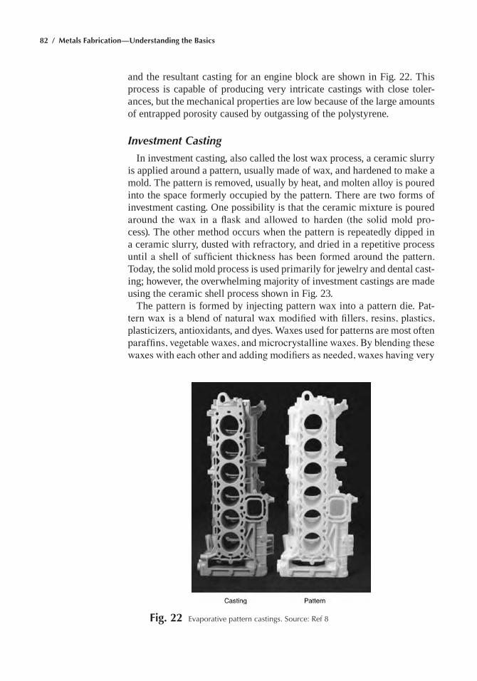
82 / Metals Fabrication—Understanding the Basics
and the resultant casting for an engine block are shown in Fig. 22. this process is capable of producing very intricate castings with close toler-ances, but the mechanical properties are low because of the large amounts of entrapped porosity caused by outgassing of the polystyrene.
Investment Casting
In investment casting, also called the lost wax process, a ceramic slurry is applied around a pattern, usually made of wax, and hardened to make a mold. the pattern is removed, usually by heat, and molten alloy is poured into the space formerly occupied by the pattern. there are two forms of investment casting. One possibility is that the ceramic mixture is poured around the wax in a flask and allowed to harden (the solid mold pro-cess). the other method occurs when the pattern is repeatedly dipped in a ceramic slurry, dusted with refractory, and dried in a repetitive process until a shell of sufficient thickness has been formed around the pattern. today, the solid mold process is used primarily for jewelry and dental cast-ing; however, the overwhelming majority of investment castings are made using the ceramic shell process shown in Fig. 23.
the pattern is formed by injecting pattern wax into a pattern die. Pat-tern wax is a blend of natural wax modified with fillers, resins, plastics, plasticizers, antioxidants, and dyes. Waxes used for patterns are most often paraffins, vegetable waxes, and microcrystalline waxes. By blending these waxes with each other and adding modifiers as needed, waxes having very
Fig. 22 evaporative pattern castings. Source: ref 8
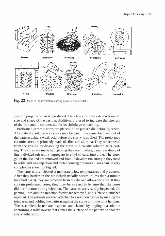
Chapter 2: Casting / 83
specific properties can be produced. The choice of a wax depends on the size and shape of the casting. additives are used to increase the strength of the wax and to compensate for its shrinkage on cooling.
Preformed ceramic cores are placed in the pattern die before injection. alternatively, soluble wax cores may be used; these are dissolved out of the pattern using a weak acid before the slurry is applied. the preformed ceramic cores are primarily made of silica and alumina. they are removed from the casting by dissolving the cores in a caustic solution after cast-ing. the cores are made by injecting the core mixture, usually a slurry of finely divided refractory aggregate in ethyl silicate, into a die. The cores gel in the die and are removed and fired to develop the strength they need to withstand wax injection and metal pouring pressures. cores can be very complex, as shown in Fig. 24.
the patterns are injected at moderately low temperatures and pressures. after they harden in the die (which usually occurs in less than a minute for small parts), they are removed from the die and allowed to cool. If they contain preformed cores, they may be x-rayed to be sure that the cores did not fracture during injection. the patterns are visually inspected, die parting lines and the injection feeder are removed, and surface blemishes repaired. the patterns are then attached to a wax downsprue by melting the joint area and holding the pattern against the sprue until the joint hardens. the assembled clusters are inspected and cleaned by dipping in a solution containing a mild solvent that etches the surface of the pattern so that the slurry adheres to it.
Fig. 23 Steps in the investment casting process. Source: ref 6
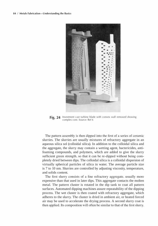
84 / Metals Fabrication—Understanding the Basics
The pattern assembly is then dipped into the first of a series of ceramic slurries. the slurries are usually mixtures of refractory aggregate in an aqueous silica sol (colloidal silica). In addition to the colloidal silica and the aggregate, the slurry may contain a wetting agent, bactericides, anti-foaming compounds, and polymers, which are added to give the slurry sufficient green strength, so that it can be re-dipped without being com-pletely dried between dips. the colloidal silica is a colloidal dispersion of virtually spherical particles of silica in water. the average particle size is 7 to 10 nm. slurries are controlled by adjusting viscosity, temperature, and solids content.
The first slurry consists of a fine refractory aggregate, usually more expensive than that used in later dips. this aggregate contacts the molten metal. the pattern cluster is rotated in the dip tank to coat all pattern surfaces. automated dipping machines assure repeatability of the dipping process. the wet cluster is then coated with refractory aggregate, which adheres to the slurry. the cluster is dried in ambient air, or heated forced air may be used to accelerate the drying process. a second slurry coat is then applied. Its composition will often be similar to that of the first slurry.
Fig. 24 Investment cast turbine blade with convex wall removed showing complex core. Source: ref 6
Chapter 2: Casting / 85
However, the refractory sand that is applied in this coat is usually more coarse and less expensive than that applied to the first coat. The cluster is dried again, and the process is repeated; this time using a coarser, less expensive refractory in the slurry and sanding operations. after about seven applications of slurry and refractory sand, the mold is given a final drying and prepared for the dewaxing operation.
the patterns are usually removed by melting or burning them out of the mold. However, because the pattern material expands about 40 times as much as the mold, care must be taken to avoid cracking the mold during this operation. Wax drain holes are often added to the cluster to provide a path for molten wax to escape during the dewaxing operation. Wax is a poor conductor of heat, so the outer layers of the pattern melt and run out of the mold before the inner parts of the pattern heat enough to expand and crack the mold. One method of dewaxing is to use a steam autoclave. In this method, superheated steam is introduced to the patterns at a pres-sure of 550 to 620 kPa (80 to 90 psig). the steam penetrates the porous mold and gives up its latent heat of vaporization on the wax surface, which heats the surface very rapidly and causes the part of the wax in contact with the steam to melt. as that wax runs out of the mold, it exposes the wax underneath to the steam, which melts it, and the process continues in this manner. the wax runs into a trough below the molds and can be recovered and reprocessed.
After dewaxing, the molds are fired at 870 to 1095 °C (1600 to 2000 °F) to remove any residual pattern material, completely dry the molds, and sinter the mold ceramic so that it develops the strength it needs for pour-ing. This operation may be combined with wax removal in flash dewaxing furnaces and with mold preheating prior to pouring. Investment casting molds are usually preheated prior to pouring to promote complete metal fill in the thin sections typical of investment castings, and to lessen the thermal shock on the molds when they are filled with molten metal.
To control solidification, the molds may be wrapped in refractory blan-kets prior to preheating. the preheat temperature is determined by the alloy being poured and the casting geometry. When the molds are com-pletely preheated, they are filled with molten metal. Because the amount of metal poured in investment castings is usually small (<20 kg, or 45 lb), the molds may be poured by hand, or they may be clamped to a furnace just large enough to melt the metal for a single mold.
melting is usually done using prealloyed charges prepared by a cus-tom alloy producer. For some alloys, notably superalloys and titanium alloys, melting, pouring, and solidification are carried out in a vacuum (approximately 10–3 torr) to protect the alloys from reactions with oxygen. Induction melting is most often used, although gas fired furnaces may be used for nonferrous alloys, and vacuum arc remelting is often used for tita-nium and refractory metal alloys. In dental and jewelry castings, the molds are often centrifuged during pouring to assure fill of the intricate designs.
86 / Metals Fabrication—Understanding the Basics
after casting, the molds cool, and the ceramic is removed. clusters are shot blasted, and the casting cut from the sprue. Finishing and inspection operations are similar to those used for sand castings; except, if preformed ceramic cores are used, they must be removed in a caustic bath. If the cores have especially small cross sections, they may be removed in a caustic autoclave, which is pulsed periodically to remove the reaction layer at the core-caustic interface. caustic (potassium hydroxide) is used to dissolve the silicate binder in the core, allowing the core aggregate material, usually silica and alumina, or an aluminosilicate, to fall out of the casting.
a number of other ceramic molding methods are based on proprietary processes that use permanent patterns and fine-grain zircon and calcined high-alumina mullite slurries for molding. they are used primarily to produce forging and extrusion tools and dies, food service equipment, glass molds, valves for the food processing, chemical, and pharmaceutical industries, and marine hardware. Dimensional control and surface fin-ish are similar to that of investment castings, but the size and weight of castings made in ceramic molds is generally greater than those made as investment castings.
Permanent Mold Casting
In permanent mold casting, liquid metal is poured into a metal mold and allowed to solidify. Due to the tooling costs, permanent mold casting is usually reserved for high-volume applications. the castings produced are normally small compared to sand castings and rather simple in shape. the process produces fairly uniform wall thicknesses but, unless segmented dies are used, is not capable of undercuts. compared to sand castings, permanent mold castings are more uniform, have better dimensional tol-erances, superior surfaces finishes, and better mechanical properties due to the faster solidification rates. Mold materials include gray cast iron and hot work die steels such as H11 and H13. When a disposable sand or plas-ter core is used with this process, it is referred to as semipermanent mold casting. another variant of the permanent mold process is low-pressure permanent mold casting. Here the casting is done inside a pressure vessel and an inert gas is used to apply 35 to 70 kPa (5 to 10 psi) pressure on the liquid metal. this results in shorter cycle times and excellent mechanical properties.
the mold material most often used is cast iron, which machines eas-ily and resists oxidation. For very high production runs, tool steels or low-carbon steels can be used. the molds often contain internal cooling passages through which water flows to remove heat from the die, and the dies are usually coated with a ceramic slurry between pours. Because metal molds extract heat more rapidly from solidifying castings, the cast structure (grain size) of permanent mold castings is generally finer, and castings have less microporosity than sand castings. casting dimensional
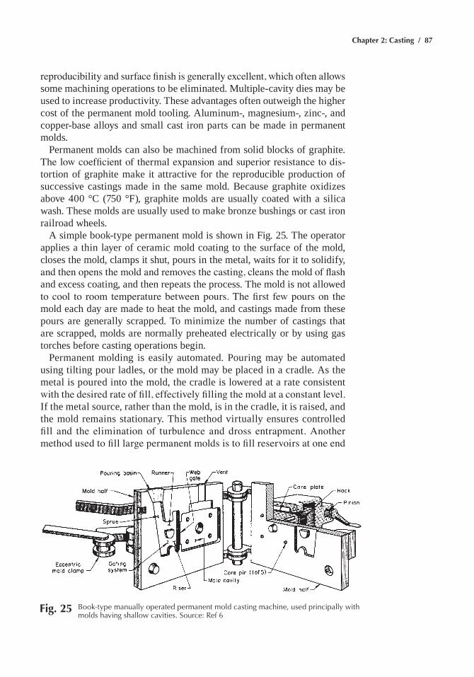
Chapter 2: Casting / 87
reproducibility and surface finish is generally excellent, which often allows some machining operations to be eliminated. multiple-cavity dies may be used to increase productivity. these advantages often outweigh the higher cost of the permanent mold tooling. aluminum-, magnesium-, zinc-, and copper-base alloys and small cast iron parts can be made in permanent molds.
Permanent molds can also be machined from solid blocks of graphite. The low coefficient of thermal expansion and superior resistance to dis-tortion of graphite make it attractive for the reproducible production of successive castings made in the same mold. Because graphite oxidizes above 400 °c (750 °F), graphite molds are usually coated with a silica wash. these molds are usually used to make bronze bushings or cast iron railroad wheels.
a simple book-type permanent mold is shown in Fig. 25. the operator applies a thin layer of ceramic mold coating to the surface of the mold, closes the mold, clamps it shut, pours in the metal, waits for it to solidify, and then opens the mold and removes the casting, cleans the mold of flash and excess coating, and then repeats the process. the mold is not allowed to cool to room temperature between pours. The first few pours on the mold each day are made to heat the mold, and castings made from these pours are generally scrapped. to minimize the number of castings that are scrapped, molds are normally preheated electrically or by using gas torches before casting operations begin.
Permanent molding is easily automated. Pouring may be automated using tilting pour ladles, or the mold may be placed in a cradle. as the metal is poured into the mold, the cradle is lowered at a rate consistent with the desired rate of fill, effectively filling the mold at a constant level. If the metal source, rather than the mold, is in the cradle, it is raised, and the mold remains stationary. this method virtually ensures controlled fill and the elimination of turbulence and dross entrapment. Another method used to fill large permanent molds is to fill reservoirs at one end
Fig. 25 Book-type manually operated permanent mold casting machine, used principally with molds having shallow cavities. Source: ref 6
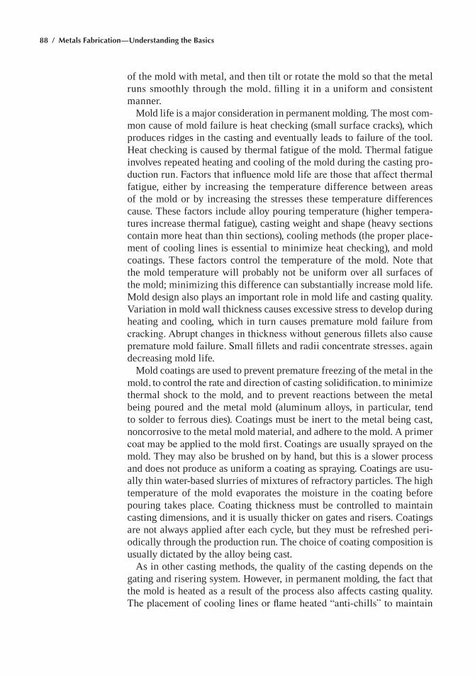
88 / Metals Fabrication—Understanding the Basics
of the mold with metal, and then tilt or rotate the mold so that the metal runs smoothly through the mold, filling it in a uniform and consistent manner.
mold life is a major consideration in permanent molding. the most com-mon cause of mold failure is heat checking (small surface cracks), which produces ridges in the casting and eventually leads to failure of the tool. Heat checking is caused by thermal fatigue of the mold. thermal fatigue involves repeated heating and cooling of the mold during the casting pro-duction run. Factors that influence mold life are those that affect thermal fatigue, either by increasing the temperature difference between areas of the mold or by increasing the stresses these temperature differences cause. these factors include alloy pouring temperature (higher tempera-tures increase thermal fatigue), casting weight and shape (heavy sections contain more heat than thin sections), cooling methods (the proper place-ment of cooling lines is essential to minimize heat checking), and mold coatings. these factors control the temperature of the mold. note that the mold temperature will probably not be uniform over all surfaces of the mold; minimizing this difference can substantially increase mold life. mold design also plays an important role in mold life and casting quality. Variation in mold wall thickness causes excessive stress to develop during heating and cooling, which in turn causes premature mold failure from cracking. Abrupt changes in thickness without generous fillets also cause premature mold failure. Small fillets and radii concentrate stresses, again decreasing mold life.
mold coatings are used to prevent premature freezing of the metal in the mold, to control the rate and direction of casting solidification, to minimize thermal shock to the mold, and to prevent reactions between the metal being poured and the metal mold (aluminum alloys, in particular, tend to solder to ferrous dies). coatings must be inert to the metal being cast, noncorrosive to the metal mold material, and adhere to the mold. a primer coat may be applied to the mold first. Coatings are usually sprayed on the mold. they may also be brushed on by hand, but this is a slower process and does not produce as uniform a coating as spraying. coatings are usu-ally thin water-based slurries of mixtures of refractory particles. the high temperature of the mold evaporates the moisture in the coating before pouring takes place. coating thickness must be controlled to maintain casting dimensions, and it is usually thicker on gates and risers. coatings are not always applied after each cycle, but they must be refreshed peri-odically through the production run. the choice of coating composition is usually dictated by the alloy being cast.
as in other casting methods, the quality of the casting depends on the gating and risering system. However, in permanent molding, the fact that the mold is heated as a result of the process also affects casting quality. The placement of cooling lines or flame heated “anti-chills” to maintain
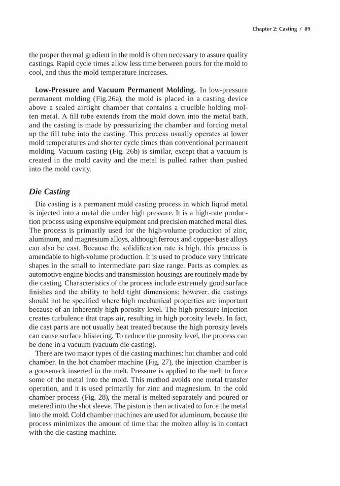
Chapter 2: Casting / 89
the proper thermal gradient in the mold is often necessary to assure quality castings. Rapid cycle times allow less time between pours for the mold to cool, and thus the mold temperature increases.
Low-Pressure and Vacuum Permanent Molding. In low-pressure permanent molding (Fig.26a), the mold is placed in a casting device above a sealed airtight chamber that contains a crucible holding mol-ten metal. A fill tube extends from the mold down into the metal bath, and the casting is made by pressurizing the chamber and forcing metal up the fill tube into the casting. This process usually operates at lower mold temperatures and shorter cycle times than conventional permanent molding. Vacuum casting (Fig. 26b) is similar, except that a vacuum is created in the mold cavity and the metal is pulled rather than pushed into the mold cavity.
Die Casting
Die casting is a permanent mold casting process in which liquid metal is injected into a metal die under high pressure. It is a high-rate produc-tion process using expensive equipment and precision matched metal dies. the process is primarily used for the high-volume production of zinc, aluminum, and magnesium alloys, although ferrous and copper-base alloys can also be cast. Because the solidification rate is high, this process is amendable to high-volume production. It is used to produce very intricate shapes in the small to intermediate part size range. Parts as complex as automotive engine blocks and transmission housings are routinely made by die casting. characteristics of the process include extremely good surface finishes and the ability to hold tight dimensions; however, die castings should not be specified where high mechanical properties are important because of an inherently high porosity level. the high-pressure injection creates turbulence that traps air, resulting in high porosity levels. In fact, die cast parts are not usually heat treated because the high porosity levels can cause surface blistering. to reduce the porosity level, the process can be done in a vacuum (vacuum die casting).
there are two major types of die casting machines: hot chamber and cold chamber. In the hot chamber machine (Fig. 27), the injection chamber is a gooseneck inserted in the melt. Pressure is applied to the melt to force some of the metal into the mold. this method avoids one metal transfer operation, and it is used primarily for zinc and magnesium. In the cold chamber process (Fig. 28), the metal is melted separately and poured or metered into the shot sleeve. the piston is then activated to force the metal into the mold. cold chamber machines are used for aluminum, because the process minimizes the amount of time that the molten alloy is in contact with the die casting machine.
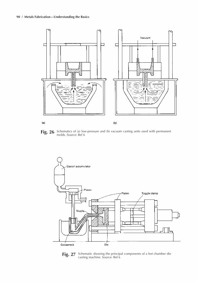
90 / Metals Fabrication—Understanding the Basics
Fig. 26 Schematics of (a) low-pressure and (b) vacuum casting units used with permanent molds. Source: ref 6
Fig. 27 Schematic showing the principal components of a hot chamber die casting machine. Source: ref 6
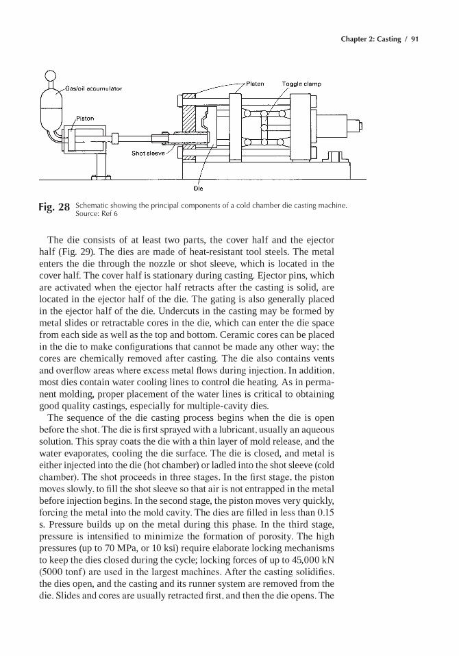
Chapter 2: Casting / 91
Fig. 28 Schematic showing the principal components of a cold chamber die casting machine. Source: ref 6
the die consists of at least two parts, the cover half and the ejector half (Fig. 29). the dies are made of heat-resistant tool steels. the metal enters the die through the nozzle or shot sleeve, which is located in the cover half. the cover half is stationary during casting. ejector pins, which are activated when the ejector half retracts after the casting is solid, are located in the ejector half of the die. the gating is also generally placed in the ejector half of the die. Undercuts in the casting may be formed by metal slides or retractable cores in the die, which can enter the die space from each side as well as the top and bottom. ceramic cores can be placed in the die to make configurations that cannot be made any other way; the cores are chemically removed after casting. the die also contains vents and overflow areas where excess metal flows during injection. In addition, most dies contain water cooling lines to control die heating. as in perma-nent molding, proper placement of the water lines is critical to obtaining good quality castings, especially for multiple-cavity dies.
the sequence of the die casting process begins when the die is open before the shot. The die is first sprayed with a lubricant, usually an aqueous solution. this spray coats the die with a thin layer of mold release, and the water evaporates, cooling the die surface. the die is closed, and metal is either injected into the die (hot chamber) or ladled into the shot sleeve (cold chamber). The shot proceeds in three stages. In the first stage, the piston moves slowly, to fill the shot sleeve so that air is not entrapped in the metal before injection begins. In the second stage, the piston moves very quickly, forcing the metal into the mold cavity. The dies are filled in less than 0.15 s. Pressure builds up on the metal during this phase. In the third stage, pressure is intensified to minimize the formation of porosity. The high pressures (up to 70 mPa, or 10 ksi) require elaborate locking mechanisms to keep the dies closed during the cycle; locking forces of up to 45,000 kn (5000 tonf) are used in the largest machines. After the casting solidifies, the dies open, and the casting and its runner system are removed from the die. Slides and cores are usually retracted first, and then the die opens. The
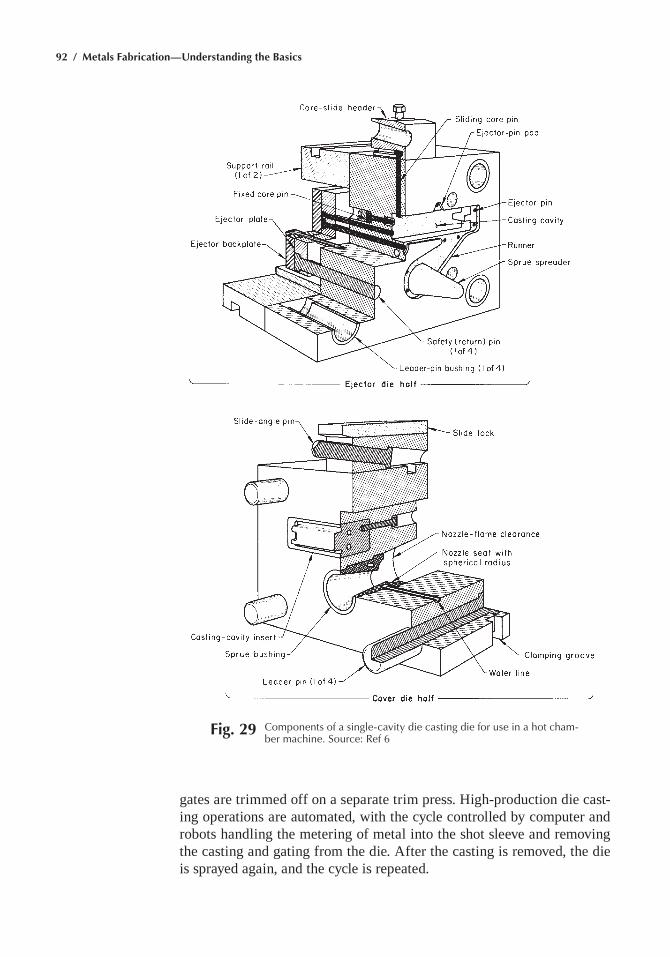
92 / Metals Fabrication—Understanding the Basics
Fig. 29 Components of a single-cavity die casting die for use in a hot cham-ber machine. Source: ref 6
gates are trimmed off on a separate trim press. High-production die cast-ing operations are automated, with the cycle controlled by computer and robots handling the metering of metal into the shot sleeve and removing the casting and gating from the die. after the casting is removed, the die is sprayed again, and the cycle is repeated.
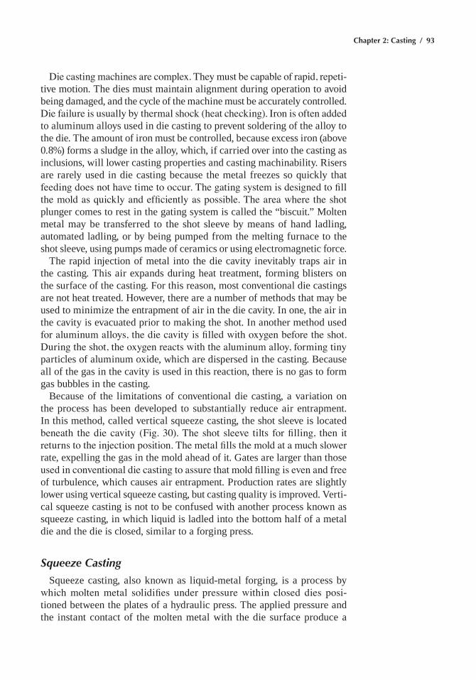
Chapter 2: Casting / 93
Die casting machines are complex. They must be capable of rapid, repeti-tive motion. the dies must maintain alignment during operation to avoid being damaged, and the cycle of the machine must be accurately controlled. Die failure is usually by thermal shock (heat checking). Iron is often added to aluminum alloys used in die casting to prevent soldering of the alloy to the die. the amount of iron must be controlled, because excess iron (above 0.8%) forms a sludge in the alloy, which, if carried over into the casting as inclusions, will lower casting properties and casting machinability. Risers are rarely used in die casting because the metal freezes so quickly that feeding does not have time to occur. The gating system is designed to fill the mold as quickly and efficiently as possible. The area where the shot plunger comes to rest in the gating system is called the “biscuit.” molten metal may be transferred to the shot sleeve by means of hand ladling, automated ladling, or by being pumped from the melting furnace to the shot sleeve, using pumps made of ceramics or using electromagnetic force.
the rapid injection of metal into the die cavity inevitably traps air in the casting. this air expands during heat treatment, forming blisters on the surface of the casting. For this reason, most conventional die castings are not heat treated. However, there are a number of methods that may be used to minimize the entrapment of air in the die cavity. In one, the air in the cavity is evacuated prior to making the shot. In another method used for aluminum alloys, the die cavity is filled with oxygen before the shot. During the shot, the oxygen reacts with the aluminum alloy, forming tiny particles of aluminum oxide, which are dispersed in the casting. Because all of the gas in the cavity is used in this reaction, there is no gas to form gas bubbles in the casting.
Because of the limitations of conventional die casting, a variation on the process has been developed to substantially reduce air entrapment. In this method, called vertical squeeze casting, the shot sleeve is located beneath the die cavity (Fig. 30). The shot sleeve tilts for filling, then it returns to the injection position. The metal fills the mold at a much slower rate, expelling the gas in the mold ahead of it. gates are larger than those used in conventional die casting to assure that mold filling is even and free of turbulence, which causes air entrapment. Production rates are slightly lower using vertical squeeze casting, but casting quality is improved. Verti-cal squeeze casting is not to be confused with another process known as squeeze casting, in which liquid is ladled into the bottom half of a metal die and the die is closed, similar to a forging press.
Squeeze Casting
squeeze casting, also known as liquid-metal forging, is a process by which molten metal solidifies under pressure within closed dies posi-tioned between the plates of a hydraulic press. the applied pressure and the instant contact of the molten metal with the die surface produce a
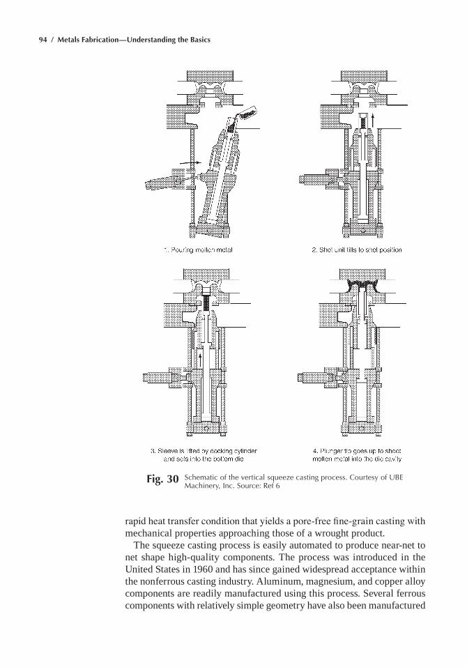
94 / Metals Fabrication—Understanding the Basics
rapid heat transfer condition that yields a pore-free fine-grain casting with mechanical properties approaching those of a wrought product.
the squeeze casting process is easily automated to produce near-net to net shape high-quality components. the process was introduced in the United states in 1960 and has since gained widespread acceptance within the nonferrous casting industry. aluminum, magnesium, and copper alloy components are readily manufactured using this process. several ferrous components with relatively simple geometry have also been manufactured
Fig. 30 Schematic of the vertical squeeze casting process. Courtesy of UBe Machinery, Inc. Source: ref 6
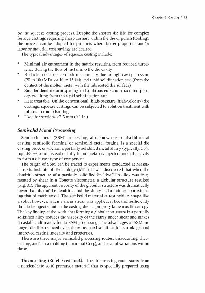
Chapter 2: Casting / 95
by the squeeze casting process. Despite the shorter die life for complex ferrous castings requiring sharp corners within the die or punch (tooling), the process can be adopted for products where better properties and/or labor or material cost savings are desired.
the typical advantages of squeeze casting include:
• minimal air entrapment in the matrix resulting from reduced turbu-lence during the flow of metal into the die cavity
• Reduction or absence of shrink porosity due to high cavity pressure (70 to 100 MPa, or 10 to 15 ksi) and rapid solidification rate (from the contact of the molten metal with the lubricated die surface)
• Smaller dendrite arm spacing and a fibrous eutectic silicon morphol-ogy resulting from the rapid solidification rate
• Heat treatable. Unlike conventional (high-pressure, high-velocity) die castings, squeeze castings can be subjected to solution treatment with minimal or no blistering.
• Used for sections >2.5 mm (0.1 in.)
Semisolid Metal Processing
semisolid metal (ssm) processing, also known as semisolid metal casting, semisolid forming, or semisolid metal forging, is a special die casting process wherein a partially solidified metal slurry (typically, 50% liquid/50% solid instead of fully liquid metal) is injected into a die cavity to form a die cast type of component.
the origin of ssm can be traced to experiments conducted at massa-chusetts Institute of technology (mIt). It was discovered that when the dendritic structure of a partially solidified Sn-15wt%Pb alloy was frag-mented by shear in a couette viscometer, a globular structure resulted (Fig. 31). the apparent viscosity of the globular structure was dramatically lower than that of the dendritic, and the slurry had a fluidity approximat-ing that of machine oil. the semisolid material at rest held its shape like a solid; however, when a shear stress was applied, it became sufficiently fluid to be injected into a die casting die—a property known as thixotropy. The key finding of the work, that forming a globular structure in a partially solidified alloy reduces the viscosity of the slurry under shear and makes it castable, ultimately led to ssm processing. the advantages of ssm are longer die life, reduced cycle times, reduced solidification shrinkage, and improved casting integrity and properties.
there are three major semisolid processing routes: thixocasting, rheo-casting, and thixomolding (thixomat corp), and several variations within those.
Thixocasting (Billet Feedstock). the thixocasting route starts from a nondendritic solid precursor material that is specially prepared using
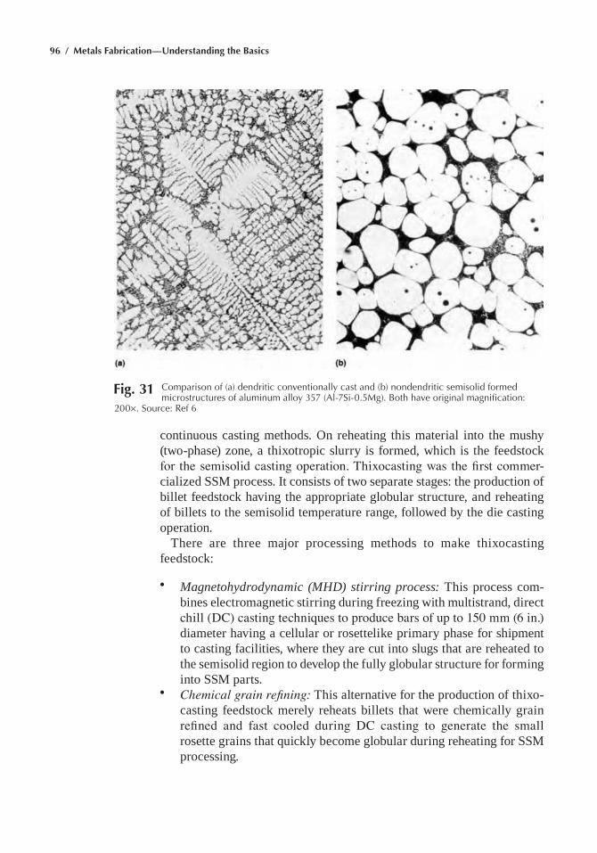
96 / Metals Fabrication—Understanding the Basics
continuous casting methods. On reheating this material into the mushy (two-phase) zone, a thixotropic slurry is formed, which is the feedstock for the semisolid casting operation. Thixocasting was the first commer-cialized ssm process. It consists of two separate stages: the production of billet feedstock having the appropriate globular structure, and reheating of billets to the semisolid temperature range, followed by the die casting operation.
there are three major processing methods to make thixocasting feedstock:
• Magnetohydrodynamic (MHD) stirring process: this process com-bines electromagnetic stirring during freezing with multistrand, direct chill (DC) casting techniques to produce bars of up to 150 mm (6 in.) diameter having a cellular or rosettelike primary phase for shipment to casting facilities, where they are cut into slugs that are reheated to the semisolid region to develop the fully globular structure for forming into ssm parts.
• Chemical grain refining: this alternative for the production of thixo-casting feedstock merely reheats billets that were chemically grain refined and fast cooled during DC casting to generate the small rosette grains that quickly become globular during reheating for ssm processing.
Fig. 31 Comparison of (a) dendritic conventionally cast and (b) nondendritic semisolid formed microstructures of aluminum alloy 357 (al-7Si-0.5Mg). Both have original magnification:
200¥. Source: ref 6
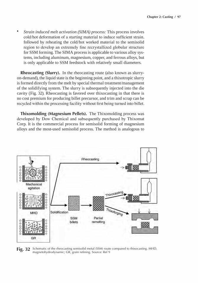
Chapter 2: Casting / 97
• Strain induced melt activation (SIMA) process: this process involves cold/hot deformation of a starting material to induce sufficient strain, followed by reheating the cold/hot worked material to the semisolid region to develop an extremely fine recrystallized globular structure for ssm forming. the sIma process is applicable to various alloy sys-tems, including aluminum, magnesium, copper, and ferrous alloys, but is only applicable to ssm feedstock with relatively small diameters.
Rheocasting (Slurry). In the rheocasting route (also known as slurry-on-demand), the liquid state is the beginning point, and a thixotropic slurry is formed directly from the melt by special thermal treatment/management of the solidifying system. the slurry is subsequently injected into the die cavity (Fig. 32). Rheocasting is favored over thixocasting in that there is no cost premium for producing billet precursor, and trim and scrap can be recycled within the processing facility without first being turned into billet.
Thixomolding (Magnesium Pellets). the thixomolding process was developed by Dow Chemical and subsequently purchased by Thixomat corp. It is the commercial process for semisolid forming of magnesium alloys and the most-used semisolid process. the method is analogous to
Fig. 32 Schematic of the rheocasting semisolid metal (SSM) route compared to thixocasting. MhD, magnetohydrodynamic; Gr, grain refining. Source: ref 9
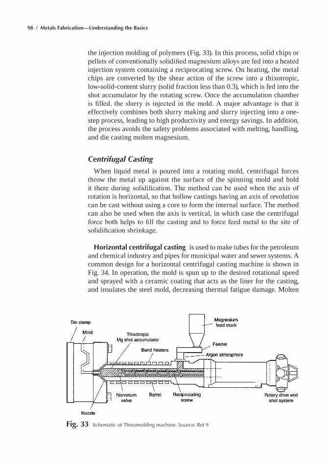
98 / Metals Fabrication—Understanding the Basics
the injection molding of polymers (Fig. 33). In this process, solid chips or pellets of conventionally solidified magnesium alloys are fed into a heated injection system containing a reciprocating screw. On heating, the metal chips are converted by the shear action of the screw into a thixotropic, low-solid-content slurry (solid fraction less than 0.3), which is fed into the shot accumulator by the rotating screw. Once the accumulation chamber is filled, the slurry is injected in the mold. A major advantage is that it effectively combines both slurry making and slurry injecting into a one-step process, leading to high productivity and energy savings. In addition, the process avoids the safety problems associated with melting, handling, and die casting molten magnesium.
Centrifugal Casting
When liquid metal is poured into a rotating mold, centrifugal forces throw the metal up against the surface of the spinning mold and hold it there during solidification. The method can be used when the axis of rotation is horizontal, so that hollow castings having an axis of revolution can be cast without using a core to form the internal surface. the method can also be used when the axis is vertical, in which case the centrifugal force both helps to fill the casting and to force feed metal to the site of solidification shrinkage.
Horizontal centrifugal casting is used to make tubes for the petroleum and chemical industry and pipes for municipal water and sewer systems. a common design for a horizontal centrifugal casting machine is shown in Fig. 34. In operation, the mold is spun up to the desired rotational speed and sprayed with a ceramic coating that acts as the liner for the casting, and insulates the steel mold, decreasing thermal fatigue damage. molten
Fig. 33 Schematic of thixomolding machine. Source: ref 9
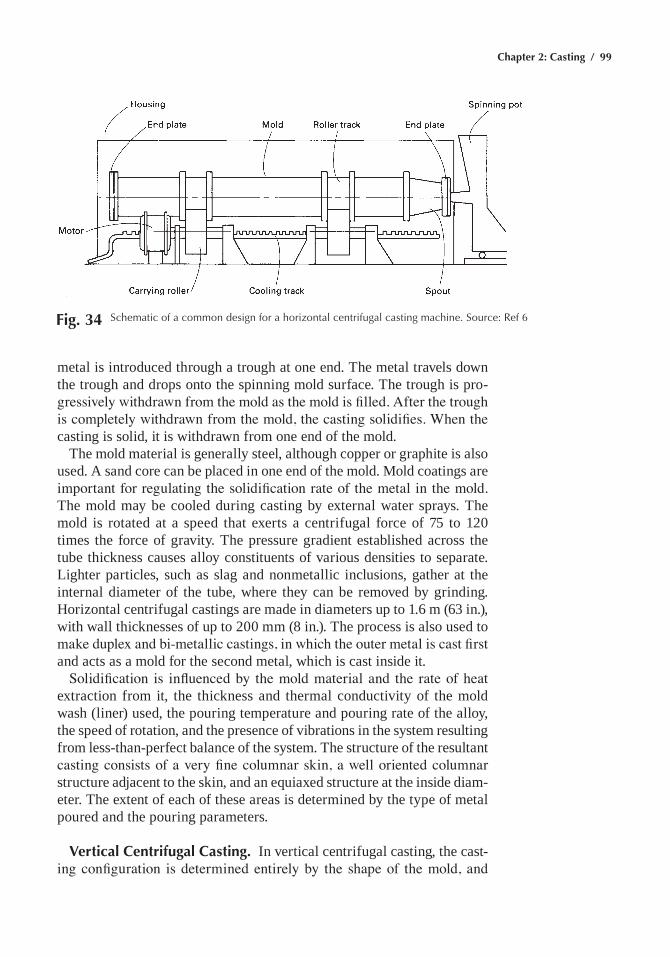
Chapter 2: Casting / 99
metal is introduced through a trough at one end. the metal travels down the trough and drops onto the spinning mold surface. the trough is pro-gressively withdrawn from the mold as the mold is filled. After the trough is completely withdrawn from the mold, the casting solidifies. When the casting is solid, it is withdrawn from one end of the mold.
the mold material is generally steel, although copper or graphite is also used. a sand core can be placed in one end of the mold. mold coatings are important for regulating the solidification rate of the metal in the mold. the mold may be cooled during casting by external water sprays. the mold is rotated at a speed that exerts a centrifugal force of 75 to 120 times the force of gravity. the pressure gradient established across the tube thickness causes alloy constituents of various densities to separate. lighter particles, such as slag and nonmetallic inclusions, gather at the internal diameter of the tube, where they can be removed by grinding. Horizontal centrifugal castings are made in diameters up to 1.6 m (63 in.), with wall thicknesses of up to 200 mm (8 in.). the process is also used to make duplex and bi-metallic castings, in which the outer metal is cast first and acts as a mold for the second metal, which is cast inside it.
Solidification is influenced by the mold material and the rate of heat extraction from it, the thickness and thermal conductivity of the mold wash (liner) used, the pouring temperature and pouring rate of the alloy, the speed of rotation, and the presence of vibrations in the system resulting from less-than-perfect balance of the system. the structure of the resultant casting consists of a very fine columnar skin, a well oriented columnar structure adjacent to the skin, and an equiaxed structure at the inside diam-eter. the extent of each of these areas is determined by the type of metal poured and the pouring parameters.
Vertical Centrifugal Casting. In vertical centrifugal casting, the cast-ing configuration is determined entirely by the shape of the mold, and
Fig. 34 Schematic of a common design for a horizontal centrifugal casting machine. Source: ref 6
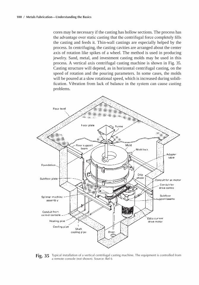
100 / Metals Fabrication—Understanding the Basics
cores may be necessary if the casting has hollow sections. the process has the advantage over static casting that the centrifugal force completely fills the casting and feeds it. thin-wall castings are especially helped by the process. In centrifuging, the casting cavities are arranged about the center axis of rotation like spikes of a wheel. the method is used in producing jewelry. sand, metal, and investment casting molds may be used in this process. a vertical axis centrifugal casting machine is shown in Fig. 35. casting structure will depend, as in horizontal centrifugal casting, on the speed of rotation and the pouring parameters. In some cases, the molds will be poured at a slow rotational speed, which is increased during solidi-fication. Vibration from lack of balance in the system can cause casting problems.
Fig. 35 typical installation of a vertical centrifugal casting machine. the equipment is controlled from a remote console (not shown). Source: ref 6
Chapter 2: Casting / 101
ACKNOWLEDGMENT
this chapter was adapted from casting in Metals Handbook Desk Edi-tion, 2nd ed., asm International, 2008.
REFERENCES
1. casting—general Introduction, Metals Handbook Desk Edition, 2nd ed., asm International, 2008
2. Solidification of Metals and Alloys, Metals Handbook Desk Edition, 2nd ed., asm International, 2008
3. R. DasGupta, Common Defects in Various Casting Processes, Cast-ing, Vol 15, ASM Handbook, asm International, 2008
4. J.R. Davis, ASM Specialty Handbook: Aluminum and Aluminum Alloys, asm International, 1993
5. melting methods, Metals Handbook Desk Edition, 2nd ed., asm International, 2008
6. molding methods, Metals Handbook Desk Edition, 2nd ed., asm International, 2008
7. F.c. campbell, Manufacturing Technology for Aerospace Structural Materials, Elsevier Scientific, 2006
8. F.c. campbell, Elements of Metallurgy and Engineering Alloys, asm International, 2008
9. Q.Y. Pan, D. Apelian, and J. Jorstad, Semisolid Casting—Introduction and Fundamentals, Casting, Vol 15, ASM Handbook, asm Interna-tional, 2008
SELECTED REFERENCES• J. campbell, Castings, Butterworth-Heinemann ltd., Oxford, england,
1993• J. campbell, Castings Practice: The Ten Rules of Castings, elsevier,
2004• Casting, Vol 15, ASM Handbook, asm International, 2008• Casting Design and Performance, asm International, 2009• a.J. clegg, Precision Casting Processes, Pergamon Press, 1991• Investment Casting, P.R. Beeley and R.F. smart, ed., the Institute of
materials, london, england, 1995• Steel Castings Handbook, 6th ed., m. Blair and t.l. stevens, ed., steel
Founders’ society of america and asm International, 1995
Copyright © 2013 ASM International®
All rights reservedwww.asminternational.org
Metals Fabrication—Understanding the BasicsF.C. Campbell, editor
Chapter 3Bulk Deformation
The Term BULK DEFORMATION implies large amounts of material movement, such as in hot rolling or forging. Bulk deformation processes used to conduct the initial breakdown of cast ingots are always conducted hot. Secondary processes, which are used to produce the final product shape, are conducted either hot or cold. Some secondary processes, such as sheet forming, do not involve large amounts of deformation.
hot working processes are conducted at temperatures above the recrys-tallization temperature, which is approximately 0.5 Tm, where Tm is the absolute melting point. Cold working processes are conducted at or near room temperature, while warm working processes are conducted at intermediate temperatures. hot working produces a recrystallized grain structure, while the grain structure due to cold working is unrecrystallized and retains the effects of the working operation.
Bulk deformation changes the shape of a workpiece by plastic deforma-tion through the application of primarily compressive forces (Fig. 1). In addition to shaping the metal, bulk deformation is used to refine the struc-ture that results from solidification. To refine the inhomogeneous structure resulting from solidification, cast ingots and continuously cast slabs are typically hot worked into intermediate product forms, such as plates, bars, and sheet. Large plastic deformation in combination with heat is very effective in refining the microstructure, breaking up macrosegregation, collapsing and sealing porosity, and refining the grain size. This product may be suitable for its intended application, but in many cases, it provides the starting material for secondary deformation processes such as drawing, hot or cold forging, and sheet metalworking.
Because most processes involve sliding contact between the workpiece and a tool or die, friction affects material flow, die pressures, and the force and energy requirements. In many instances, lubricants are used to minimize friction. Lubricants also reduce die wear, help in providing temperature control, and minimize high-temperature oxidation of the workpiece.
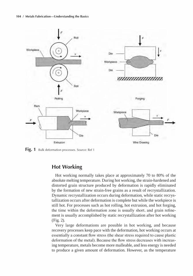
104 / Metals Fabrication—Understanding the Basics
Hot Working
hot working normally takes place at approximately 70 to 80% of the absolute melting temperature. During hot working, the strain-hardened and distorted grain structure produced by deformation is rapidly eliminated by the formation of new strain-free grains as a result of recrystallization. Dynamic recrystallization occurs during deformation, while static recrys-tallization occurs after deformation is complete but while the workpiece is still hot. For processes such as hot rolling, hot extrusion, and hot forging, the time within the deformation zone is usually short, and grain refine-ment is usually accomplished by static recrystallization after hot working (Fig. 2).
Very large deformations are possible in hot working, and because recovery processes keep pace with the deformation, hot working occurs at essentially a constant flow stress (the shear stress required to cause plastic deformation of the metal). Because the flow stress decreases with increas-ing temperature, metals become more malleable, and less energy is needed to produce a given amount of deformation. however, as the temperature
Fig. 1 Bulk deformation processes. Source: ref 1
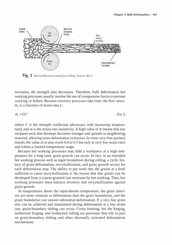
Chapter 3: Bulk Deformation / 105
increases, the strength also decreases. Therefore, bulk deformation hot working processes usually involve the use of compressive forces to prevent cracking or failure. Because recovery processes take time, the flow stress, sf, is a function of strain rate, ε :
σ = εC mf (eq 1)
where C is the strength coefficient (decreases with increasing tempera-ture), and m is the strain-rate sensitivity. A high value of m means that any incipient neck that develops becomes stronger and spreads to neighboring material, allowing more deformation in tension. In some very-fine-grained metals, the value of m may reach 0.4 to 0.5 but only at very low strain rates and within a limited temperature range.
Because hot working processes may hold a workpiece at a high tem-perature for a long time, grain growth can occur. In fact, in an extended hot working process such as ingot breakdown during rolling, a cyclic his-tory of grain deformation, recrystallization, and grain growth occurs for each deformation step. The ability to put work into the grains at a level sufficient to cause recrystallization is the reason that fine grains can be developed from a coarse-grained cast structure by hot working. Thus, hot working processes must balance recovery and recrystallization against grain growth.
At temperatures above the equicohesive temperature, the grain interi-ors are more resistant to deformation than the grain boundaries, and the grain boundaries can sustain substantial deformation. If a very fine grain size can be achieved and maintained during deformation at a low strain rate, grain-boundary sliding can occur. Creep forming, hot die forging, isothermal forging, and isothermal rolling are processes that rely in part on grain-boundary sliding and other thermally activated deformation mechanisms.
Fig. 2 recrystallization during hot rolling. Source: ref 2
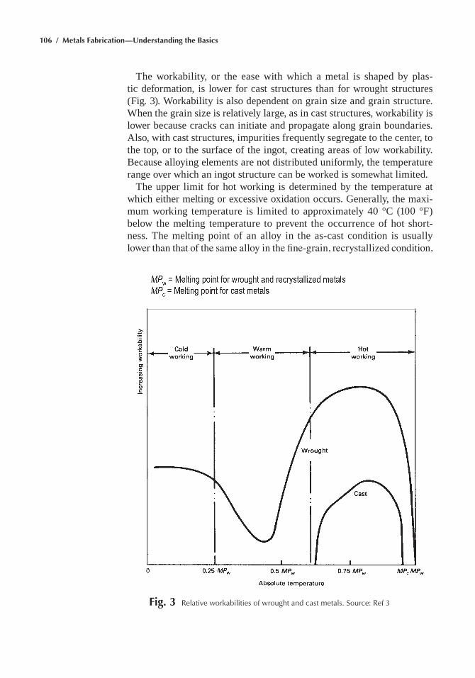
106 / Metals Fabrication—Understanding the Basics
The workability, or the ease with which a metal is shaped by plas-tic deformation, is lower for cast structures than for wrought structures (Fig. 3). Workability is also dependent on grain size and grain structure. When the grain size is relatively large, as in cast structures, workability is lower because cracks can initiate and propagate along grain boundaries. Also, with cast structures, impurities frequently segregate to the center, to the top, or to the surface of the ingot, creating areas of low workability. Because alloying elements are not distributed uniformly, the temperature range over which an ingot structure can be worked is somewhat limited.
The upper limit for hot working is determined by the temperature at which either melting or excessive oxidation occurs. Generally, the maxi-mum working temperature is limited to approximately 40 °C (100 °F) below the melting temperature to prevent the occurrence of hot short-ness. The melting point of an alloy in the as-cast condition is usually lower than that of the same alloy in the fine-grain, recrystallized condition,
Fig. 3 relative workabilities of wrought and cast metals. Source: ref 3
Chapter 3: Bulk Deformation / 107
because of chemical inhomogeneities and the presence of low-melting-point compounds that frequently occur at grain boundaries. Deformation at temperatures too close to the melting point of these compounds may lead to grain-boundary cracking when the heat developed by deforma-tion increases the workpiece temperature and produces local melting, a fracture mode called hot shortness. hot shortness can be prevented by using a sufficiently low deformation rate that allows the heat developed by deformation to be dissipated by the tooling, by using lower working temperatures, or by subjecting the workpiece to a homogenization heat treatment prior to hot working. The intermediate temperature region of low ductility shown in Fig. 3 can occur at temperatures that are sufficiently high for grain-boundary sliding to cause grain-boundary cracking but are not high enough for the cracks to be healed by dynamic recrystallization.
The advantages of hot working include:
• Flow stresses are low; hence, forces and power requirements are rela-tively low. even very large workpieces can be deformed with equipment of reasonable size.
• Ductility is high, allowing for large deformations.• Complex part shapes can be produced.
Cold Working
Cold working produces better surface finishes, can impart higher strengths, and allows thinner products than hot working but requires higher forces. Cold working results in a deformed, unrecrystallized grain structure with the grains elongated in the direction of metal flow.
An empirical relationship between flow stress and plastic strain during cold working is:
σ = εK nf (eq 2)
where sf is the flow stress, K is the strength coefficient (stress when ε = 1.0), ε is the plastic strain, and n is the work-hardening exponent.
A high strength coefficient indicates a high initial resistance to plastic flow, and metals with a high K require large forces for deformation. Work hardening is a measure of how the resistance to plastic flow increases as the metal is deformed. Typically, n has values of 0.1 to 0.5 for cold work-ing, with 0 being a perfectly plastic metal that will not work harden. A high n value allows more tensile deformation before a localized neck develops. A metal with a high work-hardening exponent but a low strength coeffi-cient will achieve a high strength level after a large amount of deformation. examples include coppers, brasses, and low-carbon steels that are cold worked to produce higher hardness and strength in the formed part. The
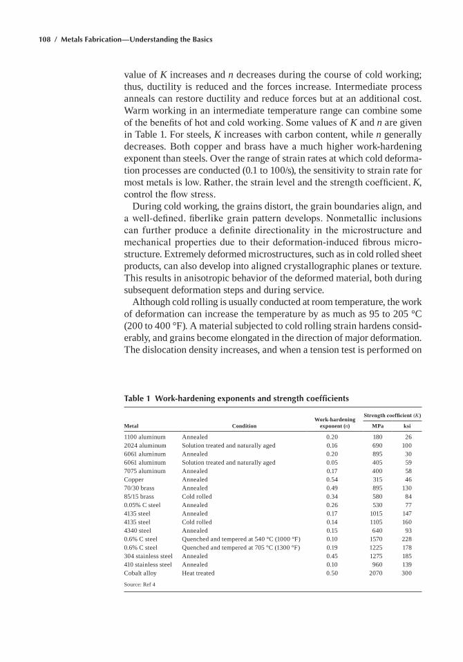
108 / Metals Fabrication—Understanding the Basics
value of K increases and n decreases during the course of cold working; thus, ductility is reduced and the forces increase. Intermediate process anneals can restore ductility and reduce forces but at an additional cost. Warm working in an intermediate temperature range can combine some of the benefits of hot and cold working. Some values of K and n are given in Table 1. For steels, K increases with carbon content, while n generally decreases. Both copper and brass have a much higher work-hardening exponent than steels. Over the range of strain rates at which cold deforma-tion processes are conducted (0.1 to 100/s), the sensitivity to strain rate for most metals is low. Rather, the strain level and the strength coefficient, K, control the flow stress.
During cold working, the grains distort, the grain boundaries align, and a well-defined, fiberlike grain pattern develops. Nonmetallic inclusions can further produce a definite directionality in the microstructure and mechanical properties due to their deformation-induced fibrous micro-structure. extremely deformed microstructures, such as in cold rolled sheet products, can also develop into aligned crystallographic planes or texture. This results in anisotropic behavior of the deformed material, both during subsequent deformation steps and during service.
Although cold rolling is usually conducted at room temperature, the work of deformation can increase the temperature by as much as 95 to 205 °C (200 to 400 °F). A material subjected to cold rolling strain hardens consid-erably, and grains become elongated in the direction of major deformation. The dislocation density increases, and when a tension test is performed on
Table 1 Work-hardening exponents and strength coefficients
Work-hardening exponent (n)
Strength coefficient (K)
Metal Condition MPa ksi
1100 aluminum Annealed 0.20 180 262024 aluminum Solution treated and naturally aged 0.16 690 1006061 aluminum Annealed 0.20 895 306061 aluminum Solution treated and naturally aged 0.05 405 597075 aluminum Annealed 0.17 400 58Copper Annealed 0.54 315 4670/30 brass Annealed 0.49 895 13085/15 brass Cold rolled 0.34 580 840.05% C steel Annealed 0.26 530 774135 steel Annealed 0.17 1015 1474135 steel Cold rolled 0.14 1105 1604340 steel Annealed 0.15 640 930.6% C steel Quenched and tempered at 540 °C (1000 °F) 0.10 1570 2280.6% C steel Quenched and tempered at 705 °C (1300 °F) 0.19 1225 178304 stainless steel Annealed 0.45 1275 185410 stainless steel Annealed 0.10 960 139Cobalt alloy heat treated 0.50 2070 300
Source: ref 4
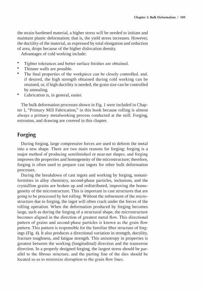
Chapter 3: Bulk Deformation / 109
the strain-hardened material, a higher stress will be needed to initiate and maintain plastic deformation; that is, the yield stress increases. however, the ductility of the material, as expressed by total elongation and reduction of area, drops because of the higher dislocation density.
Advantages of cold working include:
• Tighter tolerances and better surface finishes are obtained.• Thinner walls are possible.• The final properties of the workpiece can be closely controlled, and,
if desired, the high strength obtained during cold working can be retained, or, if high ductility is needed, the grain size can be controlled by annealing.
• Lubrication is, in general, easier.
The bulk deformation processes shown in Fig. 1 were included in Chap-ter 1, “Primary mill Fabrication,” in this book because rolling is almost always a primary metalworking process conducted at the mill. Forging, extrusion, and drawing are covered in this chapter.
Forging
During forging, large compressive forces are used to deform the metal into a new shape. There are two main reasons for forging: forging is a major method of producing semifinished or near-net shapes, and forging improves the properties and homogeneity of the microstructure; therefore, forging is often used to prepare cast ingots for other bulk deformation processes.
During the breakdown of cast ingots and working by forging, nonuni-formities in alloy chemistry, second-phase particles, inclusions, and the crystalline grains are broken up and redistributed, improving the homo-geneity of the microstructure. This is important in cast structures that are going to be processed by hot rolling. Without the refinement of the micro-structure due to forging, the ingot will often crack under the forces of the rolling operation. When the deformation produced by forging becomes large, such as during the forging of a structural shape, the microstructure becomes aligned in the direction of greatest metal flow. This directional pattern of grains and second-phase particles is known as the grain flow pattern. This pattern is responsible for the familiar fiber structure of forg-ings (Fig. 4). It also produces a directional variation in strength, ductility, fracture toughness, and fatigue strength. This anisotropy in properties is greatest between the working (longitudinal) direction and the transverse direction. In a properly designed forging, the largest stress should be par-allel to the fibrous structure, and the parting line of the dies should be located so as to minimize disruption to the grain flow lines.
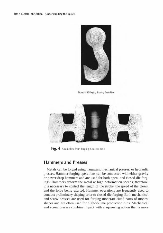
110 / Metals Fabrication—Understanding the Basics
Fig. 4 Grain flow from forging. Source: ref 5
Hammers and Presses
metals can be forged using hammers, mechanical presses, or hydraulic presses. hammer forging operations can be conducted with either gravity or power drop hammers and are used for both open- and closed-die forg-ings. hammers deform the metal at high deformation speeds; therefore, it is necessary to control the length of the stroke, the speed of the blows, and the force being exerted. hammer operations are frequently used to conduct preliminary shaping prior to closed-die forging. Both mechanical and screw presses are used for forging moderate-sized parts of modest shapes and are often used for high-volume production runs. mechanical and screw presses combine impact with a squeezing action that is more
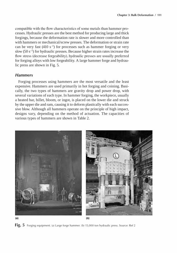
Chapter 3: Bulk Deformation / 111
compatible with the flow characteristics of some metals than hammer pro-cesses. hydraulic presses are the best method for producing large and thick forgings, because the deformation rate is slower and more controlled than with hammers or mechanical/screw presses. The deformation or strain rate can be very fast (410 s–1) for processes such as hammer forging or very slow (50 s–1) for hydraulic presses. Because higher strain rates increase the flow stress (decrease forgeability), hydraulic presses are usually preferred for forging alloys with low forgeability. A large hammer forge and hydrau-lic press are shown in Fig. 5.
Hammers
Forging processes using hammers are the most versatile and the least expensive. hammers are used primarily in hot forging and coining. Basi-cally, the two types of hammers are gravity drop and power drop, with several variations of each type. In hammer forging, the workpiece, usually a heated bar, billet, bloom, or ingot, is placed on the lower die and struck by the upper die and ram, causing it to deform plastically with each succes-sive blow. Although all hammers operate on the principle of high impact, designs vary, depending on the method of actuation. The capacities of various types of hammers are shown in Table 2.
Fig. 5 Forging equipment. (a) Large forge hammer. (b) 15,000 ton hydraulic press. Source: ref 2
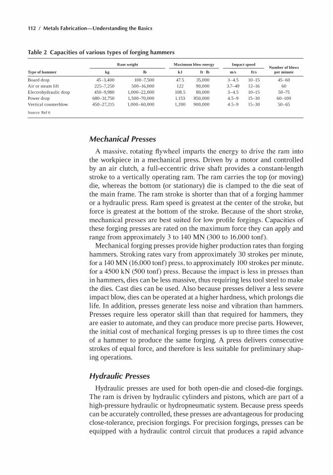
112 / Metals Fabrication—Understanding the Basics
Mechanical Presses
A massive, rotating flywheel imparts the energy to drive the ram into the workpiece in a mechanical press. Driven by a motor and controlled by an air clutch, a full-eccentric drive shaft provides a constant-length stroke to a vertically operating ram. The ram carries the top (or moving) die, whereas the bottom (or stationary) die is clamped to the die seat of the main frame. The ram stroke is shorter than that of a forging hammer or a hydraulic press. ram speed is greatest at the center of the stroke, but force is greatest at the bottom of the stroke. Because of the short stroke, mechanical presses are best suited for low profile forgings. Capacities of these forging presses are rated on the maximum force they can apply and range from approximately 3 to 140 MN (300 to 16,000 tonf).
mechanical forging presses provide higher production rates than forging hammers. Stroking rates vary from approximately 30 strokes per minute, for a 140 MN (16,000 tonf) press, to approximately 100 strokes per minute, for a 4500 kN (500 tonf) press. Because the impact is less in presses than in hammers, dies can be less massive, thus requiring less tool steel to make the dies. Cast dies can be used. Also because presses deliver a less severe impact blow, dies can be operated at a higher hardness, which prolongs die life. In addition, presses generate less noise and vibration than hammers. Presses require less operator skill than that required for hammers, they are easier to automate, and they can produce more precise parts. however, the initial cost of mechanical forging presses is up to three times the cost of a hammer to produce the same forging. A press delivers consecutive strokes of equal force, and therefore is less suitable for preliminary shap-ing operations.
Hydraulic Presses
hydraulic presses are used for both open-die and closed-die forgings. The ram is driven by hydraulic cylinders and pistons, which are part of a high-pressure hydraulic or hydropneumatic system. Because press speeds can be accurately controlled, these presses are advantageous for producing close-tolerance, precision forgings. For precision forgings, presses can be equipped with a hydraulic control circuit that produces a rapid advance
Table 2 Capacities of various types of forging hammers
Type of hammer
Ram weight Maximum blow energy Impact speedNumber of blows
per minutekg lb kJ ft ◊ lb m/s ft/s
Board drop 45–3,400 100–7,500 47.5 35,000 3–4.5 10–15 45–60Air or steam lift 225–7,250 500–16,000 122 90,000 3.7–49 12–16 60electrohydraulic drop 450–9,980 1,000–22,000 108.5 80,000 3–4.5 10–15 50–75Power drop 680–31,750 1,500–70,000 1.153 850,000 4.5–9 15–30 60–100Vertical counterblow 450–27,215 1,000–60,000 1,200 900,000 4.5–9 15–30 50–65
Source: ref 6
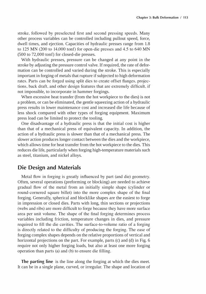
Chapter 3: Bulk Deformation / 113
stroke, followed by preselected first and second pressing speeds. Many other process variables can be controlled including pullout speed, force, dwell times, and ejection. Capacities of hydraulic presses range from 1.8 to 125 MN (200 to 14,000 tonf) for open-die presses and 4.5 to 640 MN (500 to 72,000 tonf) for closed-die presses.
With hydraulic presses, pressure can be changed at any point in the stroke by adjusting the pressure control valve. If required, the rate of defor-mation can be controlled and varied during the stroke. This is especially important in forging of metals that rupture if subjected to high deformation rates. Parts can be forged using split dies to create offset flanges, projec-tions, back draft, and other design features that are extremely difficult, if not impossible, to incorporate in hammer forgings.
When excessive heat transfer (from the hot workpiece to the dies) is not a problem, or can be eliminated, the gentle squeezing action of a hydraulic press results in lower maintenance cost and increased die life because of less shock compared with other types of forging equipment. maximum press load can be limited to protect the tooling.
One disadvantage of a hydraulic press is that the initial cost is higher than that of a mechanical press of equivalent capacity. In addition, the action of a hydraulic press is slower than that of a mechanical press. The slower action produces longer contact between the dies and the workpiece, which allows time for heat transfer from the hot workpiece to the dies. This reduces die life, particularly when forging high-temperature materials such as steel, titanium, and nickel alloys.
Die Design and Materials
Metal flow in forging is greatly influenced by part (and die) geometry. Often, several operations (preforming or blocking) are needed to achieve gradual flow of the metal from an initially simple shape (cylinder or round-cornered square billet) into the more complex shape of the final forging. Generally, spherical and blocklike shapes are the easiest to forge in impression or closed dies. Parts with long, thin sections or projections (webs and ribs) are more difficult to forge because they have more surface area per unit volume. The shape of the final forging determines process variables including friction, temperature changes in dies, and pressure required to fill the die cavities. The surface-to-volume ratio of a forging is directly related to the difficulty of producing the forging. The ease of forging complex shapes depends on the relative proportions of vertical and horizontal projections on the part. For example, parts (c) and (d) in Fig. 6 require not only higher forging loads, but also at least one more forging operation than parts (a) and (b) to ensure die filling.
The parting line is the line along the forging at which the dies meet. It can be in a single plane, curved, or irregular. The shape and location of
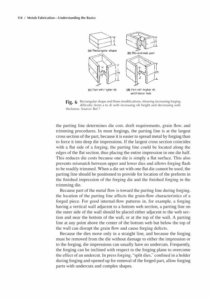
114 / Metals Fabrication—Understanding the Basics
the parting line determines die cost, draft requirements, grain flow, and trimming procedures. In most forgings, the parting line is at the largest cross section of the part, because it is easier to spread metal by forging than to force it into deep die impressions. If the largest cross section coincides with a flat side of a forging, the parting line could be located along the edges of the flat section, thus placing the entire impression in one die half. This reduces die costs because one die is simply a flat surface. This also prevents mismatch between upper and lower dies and allows forging flash to be readily trimmed. When a die set with one flat die cannot be used, the parting line should be positioned to provide for location of the preform in the finished impression of the forging die and the finished forging in the trimming die.
Because part of the metal flow is toward the parting line during forging, the location of the parting line affects the grain-flow characteristics of a forged piece. For good internal-flow patterns in, for example, a forging having a vertical wall adjacent to a bottom web section, a parting line on the outer side of the wall should be placed either adjacent to the web sec-tion and near the bottom of the wall, or at the top of the wall. A parting line at any point above the center of the bottom web but below the top of the wall can disrupt the grain flow and cause forging defects.
Because the dies move only in a straight line, and because the forging must be removed from the die without damage to either the impression or to the forging, die impressions can usually have no undercuts. Frequently, the forging can be inclined with respect to the forging plane to overcome the effect of an undercut. In press forging, “split dies,” confined in a holder during forging and opened up for removal of the forged part, allow forging parts with undercuts and complex shapes.
Fig. 6 rectangular shape and three modifications, showing increasing forging difficulty (from a to d) with increasing rib height and decreasing web
thickness. Source: ref 7
Chapter 3: Bulk Deformation / 115
Size of the Die Block. Platter is defined as the entire workpiece on which the forging equipment performs work, including the flash, sprue, tonghold, and as many forgings as are made at one time. The size of the die block is determined by the width of the finished platter, including allowance for flash and gutters and allowance for the preforming impres-sions and for sprues and gates for the blocker and finisher impressions. The impressions in a block should be spaced in such a way that the size of the die face is suitable for the size of the hammer, that flash cannot flow from one impression to another, and that the forging is not pinched in preform impressions that are too narrow. Die pressures vary with different work metals and workpiece shapes. A larger die block usually is needed as die pressure is increased.
Draft, or taper, is added to straight sidewalls of a forging to permit easier removal from the die. Forgings that have round or oval cross sec-tions or slanted sidewalls form their own draft. Forgings having straight sidewalls, such as square or rectangular sections, can be forged by parting them across the diagonal and tilting the die impression so that the part-ing line is parallel to the forging plane. The draft used in die impressions normally varies from 3° to 7° for external walls of the forged surfaces that surround holes or recesses having angles ranging from 5° to 10°. more draft is used on walls surrounding recesses to prevent the forging sticking in the die as a result of natural shrinkage of the metal as it cools.
Flash Allowance. Flash, or excess metal extruded from the finisher impression during forging, acts as a cushion for impact blows and a pres-sure-relief valve for the almost incompressible work metal. Also, it restricts the outward flow of the metal so that thin ribs and bosses can be filled in the upper die. The finisher impression generally includes a provision for flash. A typical arrangement (flash clearance, flash land, and gutter) is shown in Fig. 7.
A small amount of flash clearance in the dies, with an excess volume of work metal in the impression, requires much greater forging load or extra hammer blows to bring the forging to size. This creates excessive wear on
Fig. 7 Section through a forging, die finisher impression showing flash clear-ance, flash land, and gutter. Source: ref 7
116 / Metals Fabrication—Understanding the Basics
the flash land, produces extreme pressures within the impression, and can cause dies to break. Conversely, if the flash clearance is too great, work metal needed to fill the impression flows out through the flash land, and the forging is not properly filled. A balanced condition is needed, with just enough volume of metal to ensure that the flash clearance provided will force the work metal to fill the impression properly without causing excess wear and pressure.
Locating Impressions. The preform and finisher impressions should be positioned across the die block so the forging force is as near the center of the striking force (ram) as possible. This will minimize tipping of the ram, reduce wear on the ram guides, and help to maintain the thickness dimensions of the forging. When the forging is transferred manually to each impression, the impression for the operation requiring the greatest forging force (usually, the finisher) is placed at the center of the die block, and the remaining impressions are distributed as nearly equally as possible on each side of the die block.
Symmetrical forgings usually have their centerline along the front-to-back centerline of the die block. For asymmetrical forgings, the center of gravity can be used as a reference for positioning the preform and finisher impressions in the die block. The center of gravity of a forging does not necessarily correspond to the center of the forging force because of the influence of thin sections on the forging force. Because the increase in force is not always directly proportional to the decrease in thickness, both the flash and the location of the thin sections must be considered when locating the impressions in a die block. While evenly distributed flash has little effect on an out-of-balance condition, very thin sections have a marked effect. It is often necessary to make some calculations in order to determine the center of loading of the finisher impression.
Die Steels
hot-work die steels are commonly used for hot forging dies subjected to temperatures ranging from 315 to 650 °C (600 to 1200 °F). These materials contain chromium, tungsten, and in some cases vanadium or molybdenum or both. These alloying elements produce deep hardening and resistance to abrasion and softening. These steels are usually hardened by quenching in air or molten salt baths. The chromium-base steels contain approximately 5% Cr. high molybdenum contents gives resistance to softening, and vana-dium increases resistance to abrasion and softening. Tungsten improves toughness and hot hardness; however, tungsten-containing steels are not resistant to thermal shock and cannot be cooled intermittently with water. The tungsten-base, hot-work die steels contain 9 to 18% W, 2 to 12% Cr, and sometimes small amounts of vanadium. The high tungsten content provides resistance to softening at high temperatures while maintaining
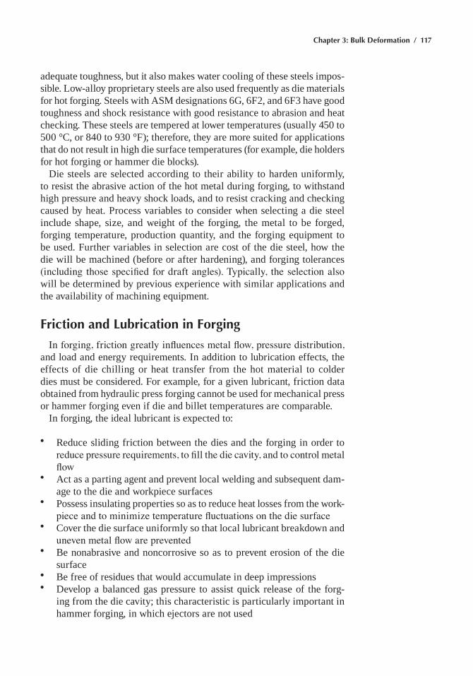
Chapter 3: Bulk Deformation / 117
adequate toughness, but it also makes water cooling of these steels impos-sible. Low-alloy proprietary steels are also used frequently as die materials for hot forging. Steels with ASm designations 6G, 6F2, and 6F3 have good toughness and shock resistance with good resistance to abrasion and heat checking. These steels are tempered at lower temperatures (usually 450 to 500 °C, or 840 to 930 °F); therefore, they are more suited for applications that do not result in high die surface temperatures (for example, die holders for hot forging or hammer die blocks).
Die steels are selected according to their ability to harden uniformly, to resist the abrasive action of the hot metal during forging, to withstand high pressure and heavy shock loads, and to resist cracking and checking caused by heat. Process variables to consider when selecting a die steel include shape, size, and weight of the forging, the metal to be forged, forging temperature, production quantity, and the forging equipment to be used. Further variables in selection are cost of the die steel, how the die will be machined (before or after hardening), and forging tolerances (including those specified for draft angles). Typically, the selection also will be determined by previous experience with similar applications and the availability of machining equipment.
Friction and Lubrication in Forging
In forging, friction greatly influences metal flow, pressure distribution, and load and energy requirements. In addition to lubrication effects, the effects of die chilling or heat transfer from the hot material to colder dies must be considered. For example, for a given lubricant, friction data obtained from hydraulic press forging cannot be used for mechanical press or hammer forging even if die and billet temperatures are comparable.
In forging, the ideal lubricant is expected to:
• reduce sliding friction between the dies and the forging in order to reduce pressure requirements, to fill the die cavity, and to control metal flow
• Act as a parting agent and prevent local welding and subsequent dam-age to the die and workpiece surfaces
• Possess insulating properties so as to reduce heat losses from the work-piece and to minimize temperature fluctuations on the die surface
• Cover the die surface uniformly so that local lubricant breakdown and uneven metal flow are prevented
• Be nonabrasive and noncorrosive so as to prevent erosion of the die surface
• Be free of residues that would accumulate in deep impressions• Develop a balanced gas pressure to assist quick release of the forg-
ing from the die cavity; this characteristic is particularly important in hammer forging, in which ejectors are not used
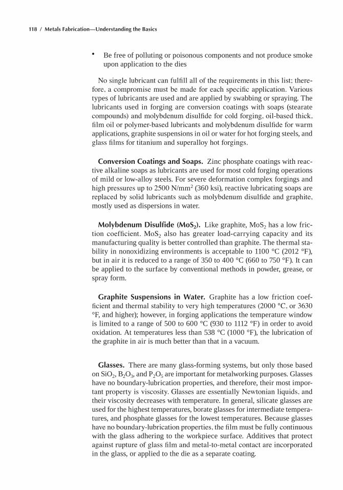
118 / Metals Fabrication—Understanding the Basics
• Be free of polluting or poisonous components and not produce smoke upon application to the dies
No single lubricant can fulfill all of the requirements in this list; there-fore, a compromise must be made for each specific application. Various types of lubricants are used and are applied by swabbing or spraying. The lubricants used in forging are conversion coatings with soaps (stearate compounds) and molybdenum disulfide for cold forging, oil-based thick, film oil or polymer-based lubricants and molybdenum disulfide for warm applications, graphite suspensions in oil or water for hot forging steels, and glass films for titanium and superalloy hot forgings.
Conversion Coatings and Soaps. Zinc phosphate coatings with reac-tive alkaline soaps as lubricants are used for most cold forging operations of mild or low-alloy steels. For severe deformation complex forgings and high pressures up to 2500 N/mm2 (360 ksi), reactive lubricating soaps are replaced by solid lubricants such as molybdenum disulfide and graphite, mostly used as dispersions in water.
Molybdenum Disulfide (MoS2). Like graphite, moS2 has a low fric-tion coefficient. MoS2 also has greater load-carrying capacity and its manufacturing quality is better controlled than graphite. The thermal sta-bility in nonoxidizing environments is acceptable to 1100 °C (2012 °F), but in air it is reduced to a range of 350 to 400 °C (660 to 750 °F). It can be applied to the surface by conventional methods in powder, grease, or spray form.
Graphite Suspensions in Water. Graphite has a low friction coef-ficient and thermal stability to very high temperatures (2000 °C, or 3630 °F, and higher); however, in forging applications the temperature window is limited to a range of 500 to 600 °C (930 to 1112 °F) in order to avoid oxidation. At temperatures less than 538 °C (1000 °F), the lubrication of the graphite in air is much better than that in a vacuum.
Glasses. There are many glass-forming systems, but only those based on SiO2, B2O3, and P2O5 are important for metalworking purposes. Glasses have no boundary-lubrication properties, and therefore, their most impor-tant property is viscosity. Glasses are essentially Newtonian liquids, and their viscosity decreases with temperature. In general, silicate glasses are used for the highest temperatures, borate glasses for intermediate tempera-tures, and phosphate glasses for the lowest temperatures. Because glasses have no boundary-lubrication properties, the film must be fully continuous with the glass adhering to the workpiece surface. Additives that protect against rupture of glass film and metal-to-metal contact are incorporated in the glass, or applied to the die as a separate coating.
Chapter 3: Bulk Deformation / 119
Fig. 8 (a) Longitudinal section through an ingot showing extensive centerline shrinkage. (b) as-forged 1038 steel bar. Longitudinal section displays
secondary pipe (black areas) that was carried along from the original bar stock into the forged piece. Gray areas are pearlite; white areas, ferrite. 2% nital. Original magnification: 50¥. Source: ref 8
Forging Imperfections
In many cases, the internal and surface imperfections that occur dur-ing forging are defects that originated during the initial hot working of ingots or billets. Figure 8 shows a secondary pipe that originated during
120 / Metals Fabrication—Understanding the Basics
ingot casting that was not closed during the forging process. A number of imperfections as a result of the forging process are shown in Fig. 9. A brief review for structural alloys follows:
• Steel alloys: The most common internal imperfections found in steel forgings are pipe, segregation, nonmetallic inclusions, and stringers. Internal flaws caused by forgings also include cracks or tears, which can result either from forging with too light a hammer or from con-tinuing forging after the metal has cooled down below a safe forging temperature. Flaws in steel forgings that can be produced by improper die design or maintenance are internal cracks and splits. If the material
Fig. 9 typical forging defects. (a) Seam in rolled 4130 steel bar. Note the linear characteristics of this flaw. (b) Micrograph of seam in (a) showing cross section of the bar. Seam is normal to the sur-
face and filled with oxide. Original magnification: 30¥. (c) Micrograph of forging lap. Note the included oxide material in the lap. Original magnification: 20¥. (d) Cross section of a forged bar showing a forging burst. the burst is located approximately at the centerline of the workpiece. arrow indicates the direction of working. Source: ref 8
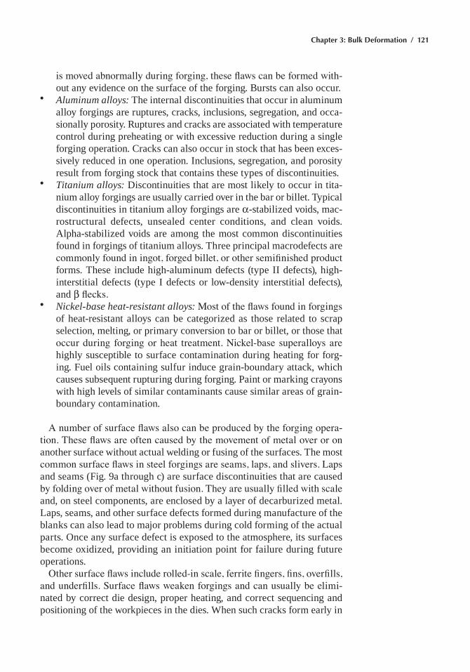
Chapter 3: Bulk Deformation / 121
is moved abnormally during forging, these flaws can be formed with-out any evidence on the surface of the forging. Bursts can also occur.
• Aluminum alloys: The internal discontinuities that occur in aluminum alloy forgings are ruptures, cracks, inclusions, segregation, and occa-sionally porosity. ruptures and cracks are associated with temperature control during preheating or with excessive reduction during a single forging operation. Cracks can also occur in stock that has been exces-sively reduced in one operation. Inclusions, segregation, and porosity result from forging stock that contains these types of discontinuities.
• Titanium alloys: Discontinuities that are most likely to occur in tita-nium alloy forgings are usually carried over in the bar or billet. Typical discontinuities in titanium alloy forgings are α-stabilized voids, mac-rostructural defects, unsealed center conditions, and clean voids. Alpha-stabilized voids are among the most common discontinuities found in forgings of titanium alloys. Three principal macrodefects are commonly found in ingot, forged billet, or other semifinished product forms. These include high-aluminum defects (type II defects), high-interstitial defects (type I defects or low-density interstitial defects), and β flecks.
• Nickel-base heat-resistant alloys: Most of the flaws found in forgings of heat-resistant alloys can be categorized as those related to scrap selection, melting, or primary conversion to bar or billet, or those that occur during forging or heat treatment. Nickel-base superalloys are highly susceptible to surface contamination during heating for forg-ing. Fuel oils containing sulfur induce grain-boundary attack, which causes subsequent rupturing during forging. Paint or marking crayons with high levels of similar contaminants cause similar areas of grain-boundary contamination.
A number of surface flaws also can be produced by the forging opera-tion. These flaws are often caused by the movement of metal over or on another surface without actual welding or fusing of the surfaces. The most common surface flaws in steel forgings are seams, laps, and slivers. Laps and seams (Fig. 9a through c) are surface discontinuities that are caused by folding over of metal without fusion. They are usually filled with scale and, on steel components, are enclosed by a layer of decarburized metal. Laps, seams, and other surface defects formed during manufacture of the blanks can also lead to major problems during cold forming of the actual parts. Once any surface defect is exposed to the atmosphere, its surfaces become oxidized, providing an initiation point for failure during future operations.
Other surface flaws include rolled-in scale, ferrite fingers, fins, overfills, and underfills. Surface flaws weaken forgings and can usually be elimi-nated by correct die design, proper heating, and correct sequencing and positioning of the workpieces in the dies. When such cracks form early in
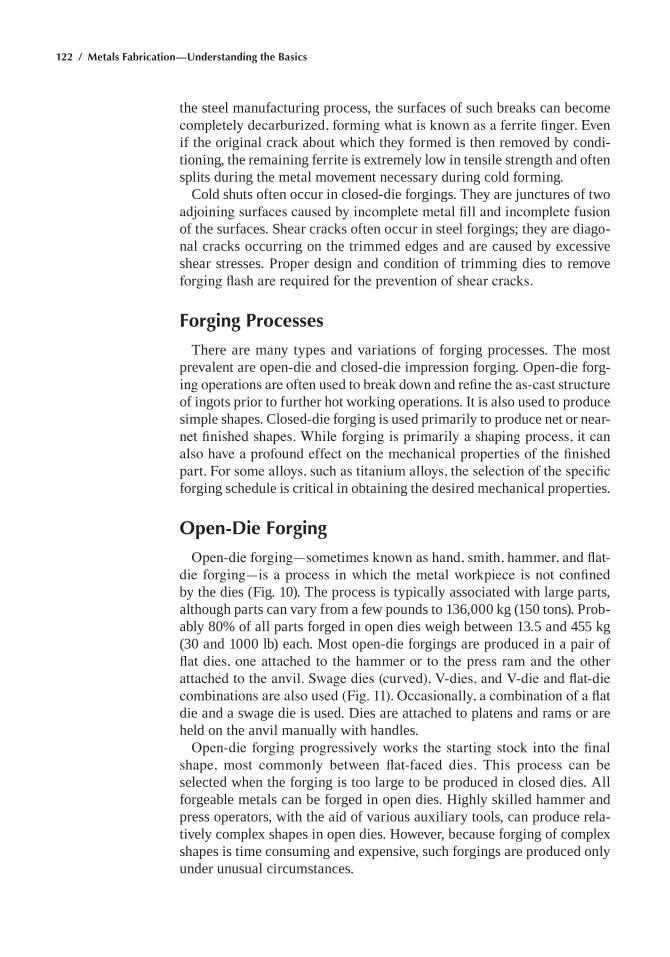
122 / Metals Fabrication—Understanding the Basics
the steel manufacturing process, the surfaces of such breaks can become completely decarburized, forming what is known as a ferrite finger. Even if the original crack about which they formed is then removed by condi-tioning, the remaining ferrite is extremely low in tensile strength and often splits during the metal movement necessary during cold forming.
Cold shuts often occur in closed-die forgings. They are junctures of two adjoining surfaces caused by incomplete metal fill and incomplete fusion of the surfaces. Shear cracks often occur in steel forgings; they are diago-nal cracks occurring on the trimmed edges and are caused by excessive shear stresses. Proper design and condition of trimming dies to remove forging flash are required for the prevention of shear cracks.
Forging Processes
There are many types and variations of forging processes. The most prevalent are open-die and closed-die impression forging. Open-die forg-ing operations are often used to break down and refine the as-cast structure of ingots prior to further hot working operations. It is also used to produce simple shapes. Closed-die forging is used primarily to produce net or near-net finished shapes. While forging is primarily a shaping process, it can also have a profound effect on the mechanical properties of the finished part. For some alloys, such as titanium alloys, the selection of the specific forging schedule is critical in obtaining the desired mechanical properties.
Open-Die Forging
Open-die forging—sometimes known as hand, smith, hammer, and flat-die forging—is a process in which the metal workpiece is not confined by the dies (Fig. 10). The process is typically associated with large parts, although parts can vary from a few pounds to 136,000 kg (150 tons). Prob-ably 80% of all parts forged in open dies weigh between 13.5 and 455 kg (30 and 1000 lb) each. most open-die forgings are produced in a pair of flat dies, one attached to the hammer or to the press ram and the other attached to the anvil. Swage dies (curved), V-dies, and V-die and flat-die combinations are also used (Fig. 11). Occasionally, a combination of a flat die and a swage die is used. Dies are attached to platens and rams or are held on the anvil manually with handles.
Open-die forging progressively works the starting stock into the final shape, most commonly between flat-faced dies. This process can be selected when the forging is too large to be produced in closed dies. All forgeable metals can be forged in open dies. highly skilled hammer and press operators, with the aid of various auxiliary tools, can produce rela-tively complex shapes in open dies. however, because forging of complex shapes is time consuming and expensive, such forgings are produced only under unusual circumstances.
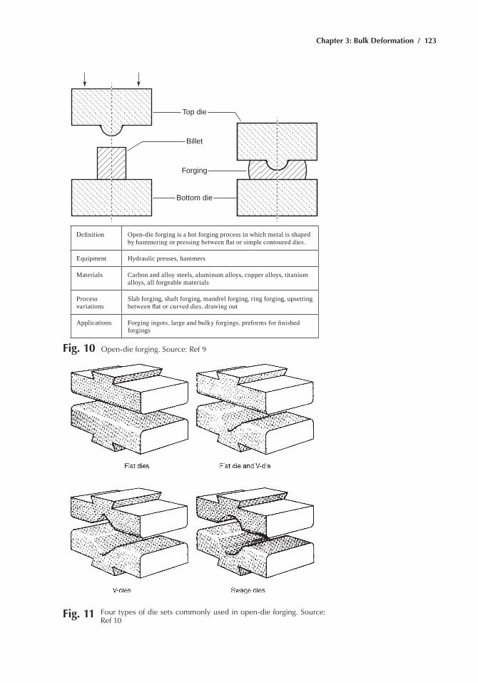
Chapter 3: Bulk Deformation / 123
Top die
Forging
Bottom die
Billet
Definition Open-die forging is a hot forging process in which metal is shaped by hammering or pressing between flat or simple contoured dies.
equipment hydraulic presses, hammers
materials Carbon and alloy steels, aluminum alloys, copper alloys, titanium alloys, all forgeable materials
Process variations
Slab forging, shaft forging, mandrel forging, ring forging, upsetting between flat or curved dies, drawing out
Applications Forging ingots, large and bulky forgings, preforms for finished forgings
Fig. 10 Open-die forging. Source: ref 9
Fig. 11 Four types of die sets commonly used in open-die forging. Source: ref 10
124 / Metals Fabrication—Understanding the Basics
most open-die forgings are rounds, squares, rectangles, hexagons, and octagons forged from billet stock, either to develop mechanical properties that are superior to those of rolled bars or to provide shapes not readily available as rolled products. hubs that have a small diameter adjacent to a large diameter can be produced in small quantities by open-die forging. Open-die forging is used to produce spindles, pinion gears, and rotors—shaftlike parts with their major or functional diameters either in the center or at one end with one or more smaller diameters extending from one or both sides of the major diameter in shaftlike extensions. Forged and pierced blanks, prior to conversion to rolled rings, are open-die forged. Various basic shapes can be developed between open dies with the aid of “loose” tooling.
Closed-Die Forging
Closed-die forging, often referred to as impression-die forging, accounts for the bulk of commercial forging production. As the name implies, two or more dies containing impressions of the part shape are brought together causing the workpiece to plastically deform with the metal flow restricted by the die contours. Closed-die forgings can be produced with flash (Fig. 12) or without flash (Fig. 13).
The forging stock, generally round or square bar, is cut to length to provide the volume of metal needed to fill the die cavity, in addition to an allowance for flash and sometimes for a projection for holding the forging. The flash allowance is, in effect, a relief valve for the extreme pressure produced in closed dies. Flash also acts as a brake to slow the outward flow of metal in order to permit complete filling of the desired configuration.
most closed-die forging is performed at elevated temperatures and is known as hot forging. Both the forging stock and the die are preheated prior to forging. Various types of electric and fuel fired furnaces are used for heating the forging stock, as well as resistance and induction heat-ing. Also in the closed-die category are cold forging and warm forging processes. Cold forging processes technically include categories such as coining. Cold forgings, produced at approximately room temperature, are generally symmetrical and typically weigh less than 11 kg (25 lb). Because of their extreme dimensional precision and fine surface finish, they often need little or no further machining. Production rates are very high with long die life. In warm forging, technically and metallurgically similar to cold forging, the workpiece is heated to “a few” hundred degrees above room temperature, but well below hot forging temperatures. Warm forging may be selected over cold forging for higher-carbon grades of steel or to eliminate subsequent annealing.
Closed-die forging is used for both low-volume or high-volume produc-tion. In addition to producing final, or nearly final, metal shapes, closed-die forging controls grain-flow direction, often improving mechanical prop-
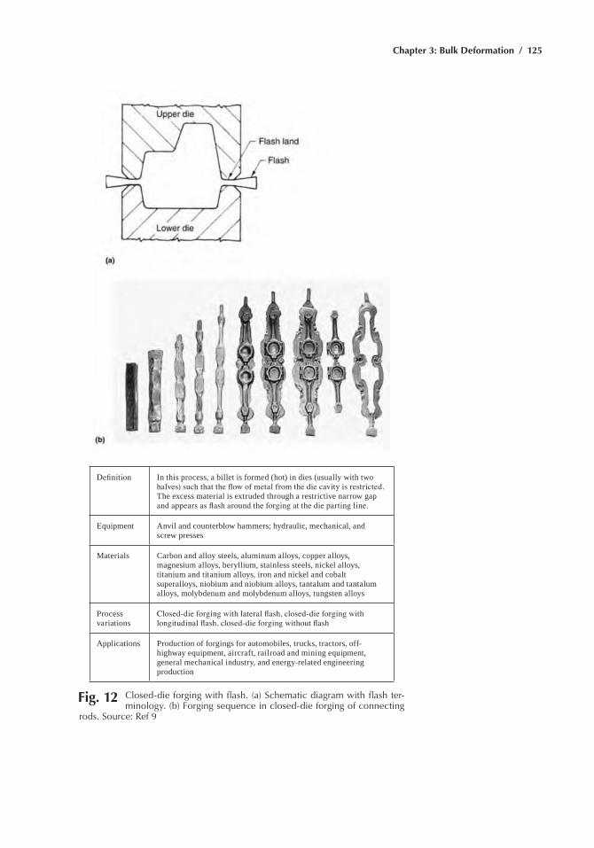
Chapter 3: Bulk Deformation / 125
Definition In this process, a billet is formed (hot) in dies (usually with two halves) such that the flow of metal from the die cavity is restricted. The excess material is extruded through a restrictive narrow gap and appears as flash around the forging at the die parting line.
equipment Anvil and counterblow hammers; hydraulic, mechanical, and screw presses
materials Carbon and alloy steels, aluminum alloys, copper alloys, magnesium alloys, beryllium, stainless steels, nickel alloys, titanium and titanium alloys, iron and nickel and cobalt superalloys, niobium and niobium alloys, tantalum and tantalum alloys, molybdenum and molybdenum alloys, tungsten alloys
Process variations
Closed-die forging with lateral flash, closed-die forging with longitudinal flash, closed-die forging without flash
Applications Production of forgings for automobiles, trucks, tractors, off-highway equipment, aircraft, railroad and mining equipment, general mechanical industry, and energy-related engineering production
Fig. 12 Closed-die forging with flash. (a) Schematic diagram with flash ter-minology. (b) Forging sequence in closed-die forging of connecting
rods. Source: ref 9
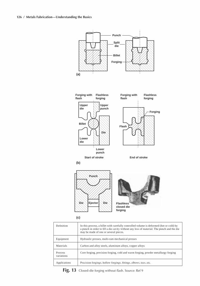
126 / Metals Fabrication—Understanding the Basics
Punch
Forging
(a)
(b)
(c)
Billet
Forging withflash
Upperdie
Upperpunch
Lowerpunch
Start of stroke End of stroke
Lowerdie
Die
Die Die
Billet
Ejector
Punch
Flash
Forging withflash
Flashlessforging
Flashlessclosed dieforging
Flashlessforging
Forging
Splitdie
Definition In this process, a billet with carefully controlled volume is deformed (hot or cold) by a punch in order to fill a die cavity without any loss of material. The punch and the die may be made of one or several pieces.
equipment hydraulic presses, multi-ram mechanical presses
materials Carbon and alloy steels, aluminum alloys, copper alloys
Process variations
Core forging, precision forging, cold and warm forging, powder metallurgy forging
Applications Precision forgings, hollow forgings, fittings, elbows, tees, etc.
Fig. 13 Closed-die forging without flash. Source: ref 9
Chapter 3: Bulk Deformation / 127
erties in the longitudinal direction of the workpiece. The size of forgings produced in closed, impression dies can range from a few ounces to several tons. The maximum size that can be produced is limited only by the equip-ment that is available for handling and for forging. Steel forgings weighing as much as 25,400 kg (56,000 lb) have been closed-die forged. Typically, however, more than 70% of the closed-die forgings produced weigh 0.9 kg (2 lb) or less.
Complex nonsymmetrical shapes that require a minimum number of operations for completion are suitable for closed-die forging. In addition, the process can be used in combination with other processes to produce parts having greater complexity or closer tolerances than are possible by forging alone. Cold coining and the assembly of two or more closed-die forgings by welding are examples of other processes that can extend the useful range of closed-die forging.
materials used for closed-die forgings must satisfy two basic require-ments. First, the material strength (or flow stress) must be low to hold die pressures to within the capabilities of practical die materials and construc-tions. Also, the forgeability of the material (its ability to deform without failure) must be equal to the amount of deformation required in the die. These conditions are usually met by heating the material to be forged.
Classification of Closed-Die Forgings
Closed-die forgings are generally classified as blocker-type, conven-tional, and close-tolerance.
Blocker-type forgings are produced with generous allowance for fin-ishing. These forgings are produced in relatively inexpensive dies, but their weight and dimensions are somewhat greater than those of conventional closed-die forgings. Often blocker-type forgings are specified when only a small number of forgings are required and the cost of machining parts to final shape is not excessive. Blocker-type forgings can be produced in metal die blocks containing cavities of simple shape, or with stops and gages that the forging producer has in stock. These are called “loose” tools because they are not attached to the ram or anvil but are held in position on a bottom flat die by a handle. Loose tooling can be used to produce a vari-ety of simple shapes, on short notice, without the high cost of dies. Because they lack the detail and the dimensional accuracy of forgings completed in finisher dies by conventional closed-die forging methods, forgings pro-duced in loose tooling usually require substantially more machining to provide a finished part.
Conventional closed-die forgings are the most common. They can be complex in shape with tolerances that fall within the broad range of general forging practice. Because they are made closer to the shape and
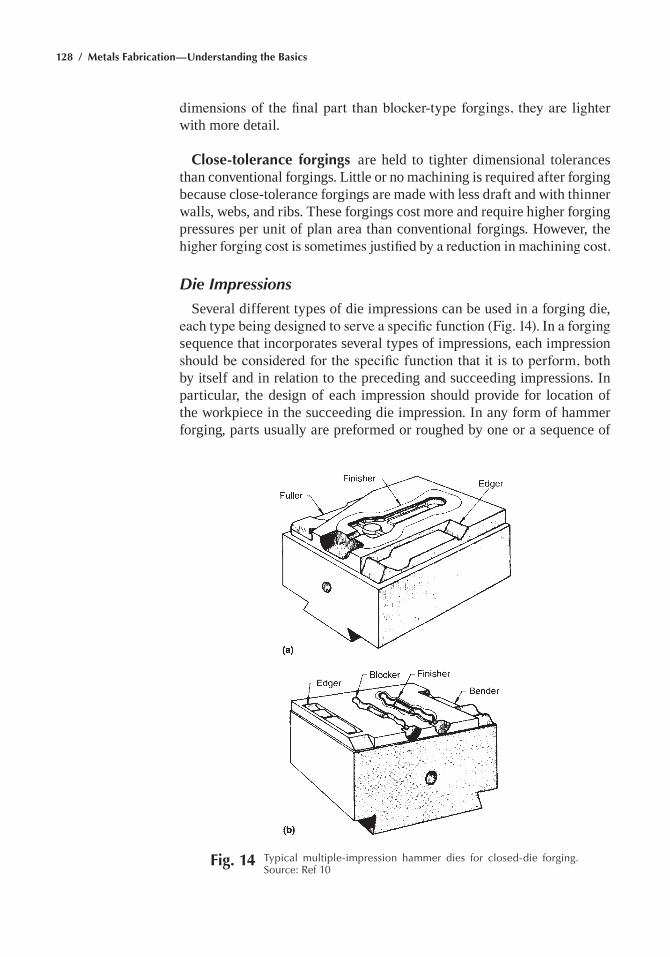
128 / Metals Fabrication—Understanding the Basics
dimensions of the final part than blocker-type forgings, they are lighter with more detail.
Close-tolerance forgings are held to tighter dimensional tolerances than conventional forgings. Little or no machining is required after forging because close-tolerance forgings are made with less draft and with thinner walls, webs, and ribs. These forgings cost more and require higher forging pressures per unit of plan area than conventional forgings. however, the higher forging cost is sometimes justified by a reduction in machining cost.
Die Impressions
Several different types of die impressions can be used in a forging die, each type being designed to serve a specific function (Fig. 14). In a forging sequence that incorporates several types of impressions, each impression should be considered for the specific function that it is to perform, both by itself and in relation to the preceding and succeeding impressions. In particular, the design of each impression should provide for location of the workpiece in the succeeding die impression. In any form of hammer forging, parts usually are preformed or roughed by one or a sequence of
Fig. 14 typical multiple-impression hammer dies for closed-die forging. Source: ref 10
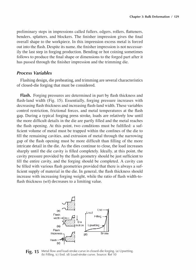
Chapter 3: Bulk Deformation / 129
preliminary steps in impressions called fullers, edgers, rollers, flatteners, benders, splatters, and blockers. The finisher impression gives the final overall shape to the workpiece. In this impression excess metal is forced out into the flash. Despite its name, the finisher impression is not necessar-ily the last step in forging production. Bending or hot coining sometimes follows to produce the final shape or dimensions to the forged part after it has passed through the finisher impression and the trimming die.
Process Variables
Flashing design, die preheating, and trimming are several characteristics of closed-die forging that must be considered.
Flash. Forging pressures are determined in part by flash thickness and flash-land width (Fig. 15). Essentially, forging pressure increases with decreasing flash thickness and increasing flash-land width. These variables control restriction, frictional forces, and metal temperatures at the flash gap. During a typical forging press stroke, loads are relatively low until the more difficult details in the die are partly filled and the metal reaches the flash opening. At this point, two conditions must be fulfilled: a suf-ficient volume of metal must be trapped within the confines of the die to fill the remaining cavities, and extrusion of metal through the narrowing gap of the flash opening must be more difficult than filling of the more intricate detail in the die. As the dies continue to close, the load increases sharply until the die cavity is filled completely. Ideally, at this point, the cavity pressure provided by the flash geometry should be just sufficient to fill the entire cavity, and the forging should be completed. A cavity can be filled with various flash geometries provided that there is always a suf-ficient supply of material in the die. In general, the flash thickness should increase with increasing forging weight, while the ratio of flash width-to-flash thickness (w/t) decreases to a limiting value.
Fig. 15 Metal flow and load-stroke curve in closed-die forging. (a) Upsetting. (b) Filling. (c) end. (d) Load-stroke curve. Source: ref 10
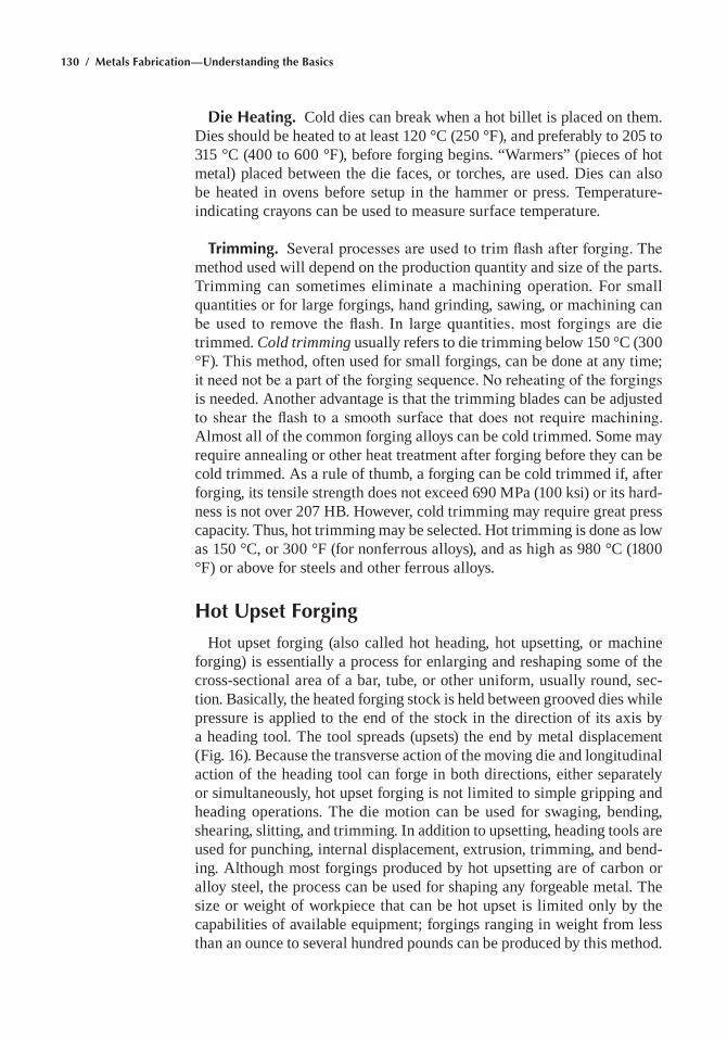
130 / Metals Fabrication—Understanding the Basics
Die Heating. Cold dies can break when a hot billet is placed on them. Dies should be heated to at least 120 °C (250 °F), and preferably to 205 to 315 °C (400 to 600 °F), before forging begins. “Warmers” (pieces of hot metal) placed between the die faces, or torches, are used. Dies can also be heated in ovens before setup in the hammer or press. Temperature-indicating crayons can be used to measure surface temperature.
Trimming. Several processes are used to trim flash after forging. The method used will depend on the production quantity and size of the parts. Trimming can sometimes eliminate a machining operation. For small quantities or for large forgings, hand grinding, sawing, or machining can be used to remove the flash. In large quantities, most forgings are die trimmed. Cold trimming usually refers to die trimming below 150 °C (300 °F). This method, often used for small forgings, can be done at any time; it need not be a part of the forging sequence. No reheating of the forgings is needed. Another advantage is that the trimming blades can be adjusted to shear the flash to a smooth surface that does not require machining. Almost all of the common forging alloys can be cold trimmed. Some may require annealing or other heat treatment after forging before they can be cold trimmed. As a rule of thumb, a forging can be cold trimmed if, after forging, its tensile strength does not exceed 690 mPa (100 ksi) or its hard-ness is not over 207 hB. however, cold trimming may require great press capacity. Thus, hot trimming may be selected. hot trimming is done as low as 150 °C, or 300 °F (for nonferrous alloys), and as high as 980 °C (1800 °F) or above for steels and other ferrous alloys.
Hot Upset Forging
hot upset forging (also called hot heading, hot upsetting, or machine forging) is essentially a process for enlarging and reshaping some of the cross-sectional area of a bar, tube, or other uniform, usually round, sec-tion. Basically, the heated forging stock is held between grooved dies while pressure is applied to the end of the stock in the direction of its axis by a heading tool. The tool spreads (upsets) the end by metal displacement (Fig. 16). Because the transverse action of the moving die and longitudinal action of the heading tool can forge in both directions, either separately or simultaneously, hot upset forging is not limited to simple gripping and heading operations. The die motion can be used for swaging, bending, shearing, slitting, and trimming. In addition to upsetting, heading tools are used for punching, internal displacement, extrusion, trimming, and bend-ing. Although most forgings produced by hot upsetting are of carbon or alloy steel, the process can be used for shaping any forgeable metal. The size or weight of workpiece that can be hot upset is limited only by the capabilities of available equipment; forgings ranging in weight from less than an ounce to several hundred pounds can be produced by this method.
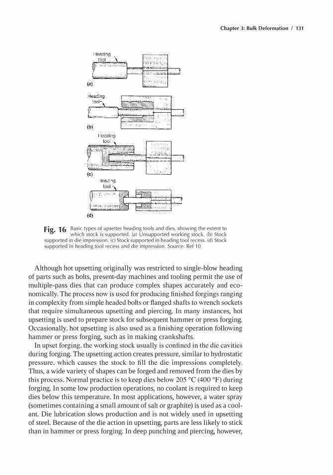
Chapter 3: Bulk Deformation / 131
Although hot upsetting originally was restricted to single-blow heading of parts such as bolts, present-day machines and tooling permit the use of multiple-pass dies that can produce complex shapes accurately and eco-nomically. The process now is used for producing finished forgings ranging in complexity from simple headed bolts or flanged shafts to wrench sockets that require simultaneous upsetting and piercing. In many instances, hot upsetting is used to prepare stock for subsequent hammer or press forging. Occasionally, hot upsetting is also used as a finishing operation following hammer or press forging, such as in making crankshafts.
In upset forging, the working stock usually is confined in the die cavities during forging. The upsetting action creates pressure, similar to hydrostatic pressure, which causes the stock to fill the die impressions completely. Thus, a wide variety of shapes can be forged and removed from the dies by this process. Normal practice is to keep dies below 205 °C (400 °F) during forging. In some low production operations, no coolant is required to keep dies below this temperature. In most applications, however, a water spray (sometimes containing a small amount of salt or graphite) is used as a cool-ant. Die lubrication slows production and is not widely used in upsetting of steel. Because of the die action in upsetting, parts are less likely to stick than in hammer or press forging. In deep punching and piercing, however,
Fig. 16 Basic types of upsetter heading tools and dies, showing the extent to which stock is supported. (a) Unsupported working stock. (b) Stock
supported in die impression. (c) Stock supported in heading tool recess. (d) Stock supported in heading tool recess and die impression. Source: ref 10
132 / Metals Fabrication—Understanding the Basics
sticking may be encountered, thus requiring a lubricant. An oil-graphite spray is effective and can simultaneously provide adequate cooling. A recirculated suspension of alumina in water is used in some high produc-tion operations.
Roll Forging
roll forging (also known as hot forge rolling) is a process for reducing the cross-sectional area of heated bars or billets by passing them between two driven rolls that rotate in opposite directions and have one or more matching grooves in each roll. The principle involved in reducing the cross-sectional area of the work metal in roll forging is essentially the same as that employed in rolling mills to reduce billets to bars. Any metal that can be forged by other methods can be roll forged. heating times and temperatures are the same as those used in the forging of metals in open or closed dies.
In machines for roll forging (often called forge rolls, reducer rolls, back rolls, or gap rolls), the driving motor is mounted at the top of the main housing (Fig. 17). The motor drives a large flywheel by means of V-belts. In turn, the flywheel drives the roll shafts, to which the roll dies are attached, through a system of gears. Forging rolls are available in numerous sizes and have the capacity to roll blanks up to 127 mm (5 in.) thick and 1020 mm (40 in.) long. roll dies are bolted to the roll shafts, which rotate in opposite directions during operation. roll dies (or their effective forging portion) usually occupy approximately one-half the total circumference; therefore, at least some forging action takes place during half of the revolu-tion. machines can be operated continuously or stopped between passes, as required. In the roll forging of long tapered workpieces, the more common practice is to operate the machine intermittently.
Fig. 17 roll-forging machine with outboard housing. Source: ref 10
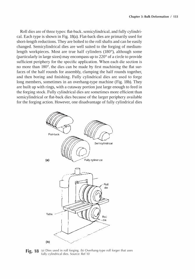
Chapter 3: Bulk Deformation / 133
Roll dies are of three types: flat-back, semicylindrical, and fully cylindri-cal. each type is shown in Fig. 18(a). Flat-back dies are primarily used for short-length reductions. They are bolted to the roll shafts and can be easily changed. Semicylindrical dies are well suited to the forging of medium-length workpieces. most are true half cylinders (180°), although some (particularly in large sizes) may encompass up to 220° of a circle to provide sufficient periphery for the specific application. When each die section is no more than 180°, the dies can be made by first machining the flat sur-faces of the half rounds for assembly, clamping the half rounds together, and then boring and finishing. Fully cylindrical dies are used to forge long members, sometimes in an overhang-type machine (Fig. 18b). They are built up with rings, with a cutaway portion just large enough to feed in the forging stock. Fully cylindrical dies are sometimes more efficient than semicylindrical or flat-back dies because of the larger periphery available for the forging action. however, one disadvantage of fully cylindrical dies
Fig. 18 (a) Dies used in roll forging. (b) Overhang-type roll forger that uses fully cylindrical dies. Source: ref 10
134 / Metals Fabrication—Understanding the Basics
is that the small opening prevents continuous operation; consequently, motion must be controlled by a clutch and a brake.
roll forging can be used either as the sole or main operation in pro-ducing a shape. Generally this involves the shaping of long, thin, usually tapered parts. Typical examples are airplane propeller-blade half sections, tapered axle shafts, tapered leaf springs, table-knife blades, hand shovels and spades, various agricultural tools (such as pitchforks), and tradesman’s tools (such as chisels and trowels). roll forging is sometimes followed by the upsetting of one end of the workpiece to form a flange, as in the forging of axle shafts. roll forging is also used as a preliminary operation to save material and number of hits in subsequent forging in closed dies. Applica-tions in this case include preliminary shaping of stock prior to forging in impression dies in either a press or hammer, thus eliminating a fullering or blocking operation. Crankshafts, connecting rods, and other automotive parts are typical products that are first roll forged from billets to preform stock and then finish forged in a press.
High-Energy-Rate Forging
high-energy-rate forging (herF), sometimes called high-velocity forg-ing, is a closed-die, hot or cold forging process in which the stored energy of high-pressure gas is used to accelerate a ram to unusually high veloci-ties to deform the workpiece. Ideally, the final configuration of the forging is developed in one blow or, at most, a few blows. In herF, the velocity of the ram, rather than its mass, generates the major forging force. The maximum impact velocity of herF machines is approximately three to four times that of conventional drop hammers. Typically, the ram veloc-ity at impact in the herF machine is in the range of 5 to 22 m/s (16 to 72 ft/s), while ram velocities range from 4.5 to 9.1 m/s (15 to 30 ft/s) for a power-drop hammer and from 3.6 to 5.5 m/s (12 to 18 ft/s) for a gravity-drop hammer.
high-energy-rate machines can be used to hot forge parts of the same general shapes as those produced with conventional hammers and presses. however, the work metal must be capable of undergoing extremely rapid deformation rates as it fills the die cavity without rupturing it. In HERF, the high ram velocities forge parts with thin webs, high rib height-to-width ratios, and small draft angles to profiles sufficiently accurate that machin-ing allowance can sometimes be as little as 0.500 mm (0.0197 in.). even parts made of difficult-to-forge metals can be formed close to finished dimensions in a few blows and often without reheating.
For a given forming capacity, high-speed machines are much smaller than conventional forging machines, and they require much less installa-tion/foundation and therefore a lower capital investment. These advantages arise because the principle used in these machines involves the conversion of the kinetic energy of a ram/platen into forming work. Kinetic energy
Chapter 3: Bulk Deformation / 135
is proportional to the square of the impact velocity; therefore, a threefold increase in impact speed produces a ninefold increase in forming energy. high-energy-rate forging machines are typically one-ninth the bulk and weight of equivalent slow-speed machines. Although the finished forging is generally made in one high-speed blow, some machines can be fired two or three times before the work metal has cooled below the forging temperature. In general, complex parts can be forged in one blow from a billet or a preform. Many metals that are difficult to forge by other methods can be successfully forged by herF. Dimensional accuracy, surface detail, and, often, surface finish are better with HERF than other techniques. Draft allowances, both internal and external, can be reduced or, in some applications, eliminated. Forgings are made to size or with a minimum of machining allowance. reduced machining lowers the induced mechani-cal stress and minimizes the cutting of end grain, which improves the stress-corrosion resistance of some metals, notably aluminum. Deep, thin sections can be high-energy-rate forged because the rapidity of the blow provides little time for heat transfer to the die walls. Severe deformation possible with HERF provides a high degree of grain refinement in some metals.
however, herF does have several limitations. Sharp corners and small radii cannot be forged without causing undue wear. The process is gener-ally limited to symmetrical parts, although some asymmetrical parts can be forged from preformed billets. high-energy-rate forging part size is limited to approximately 11 to 12 kg (24 to 26 lb) for carbon steel forgings and to lesser weights for forgings made of stainless steel or heat-resistant alloys. The production rate is about the same as in hammer or hydraulic press forging but is slower than in mechanical press forging. however, dies must be carefully designed and fabricated in order to withstand the high impact; compressive prestressing of the die inserts by a shrink ring is a common practice.
The three basic types of herF machines (Fig. 19) are ram-and-inner-frame, two-ram, and controlled-energy-flow (counterblow). The cycle time for a herF machine is 12 to 20 s per piece, or a production rate of 180 to 300 parts per hour. Therefore, herF machines can make parts to close profiles at production rates often comparable to those of drop hammer and hydraulic presses. Adaptation of automatic transfer equipment to herF further increases the production rates to levels competitive with manually operated mechanical presses. The machines are readily adaptable to auto-matic loading and unloading equipment. however, high production runs or multiple runs of similar parts are needed to justify the cost of automatic handling equipment.
Like conventional forging, herF is performed over a broad range of temperatures, depending on the specific part, the material, and the design requirements. Three categories of herF are hot forging, cold forging, and warm forging. hot herF can sometimes be used to forge parts that can-
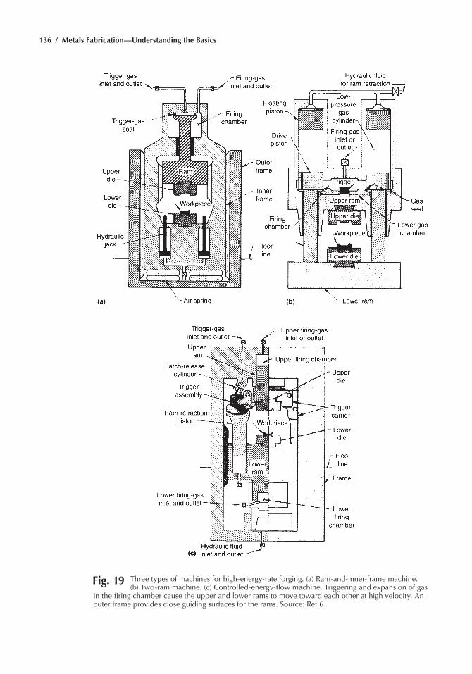
136 / Metals Fabrication—Understanding the Basics
Fig. 19 three types of machines for high-energy-rate forging. (a) ram-and-inner-frame machine. (b) two-ram machine. (c) Controlled-energy-flow machine. triggering and expansion of gas
in the firing chamber cause the upper and lower rams to move toward each other at high velocity. an outer frame provides close guiding surfaces for the rams. Source: ref 6
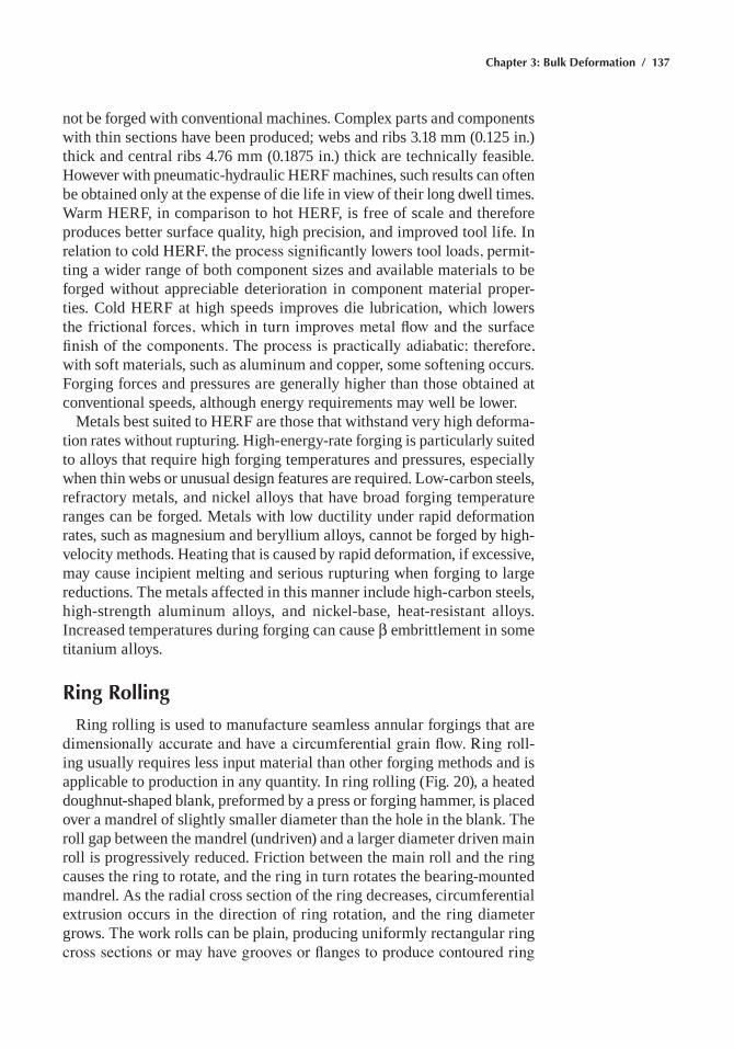
Chapter 3: Bulk Deformation / 137
not be forged with conventional machines. Complex parts and components with thin sections have been produced; webs and ribs 3.18 mm (0.125 in.) thick and central ribs 4.76 mm (0.1875 in.) thick are technically feasible. however with pneumatic-hydraulic herF machines, such results can often be obtained only at the expense of die life in view of their long dwell times. Warm herF, in comparison to hot herF, is free of scale and therefore produces better surface quality, high precision, and improved tool life. In relation to cold HERF, the process significantly lowers tool loads, permit-ting a wider range of both component sizes and available materials to be forged without appreciable deterioration in component material proper-ties. Cold herF at high speeds improves die lubrication, which lowers the frictional forces, which in turn improves metal flow and the surface finish of the components. The process is practically adiabatic; therefore, with soft materials, such as aluminum and copper, some softening occurs. Forging forces and pressures are generally higher than those obtained at conventional speeds, although energy requirements may well be lower.
metals best suited to herF are those that withstand very high deforma-tion rates without rupturing. high-energy-rate forging is particularly suited to alloys that require high forging temperatures and pressures, especially when thin webs or unusual design features are required. Low-carbon steels, refractory metals, and nickel alloys that have broad forging temperature ranges can be forged. metals with low ductility under rapid deformation rates, such as magnesium and beryllium alloys, cannot be forged by high-velocity methods. heating that is caused by rapid deformation, if excessive, may cause incipient melting and serious rupturing when forging to large reductions. The metals affected in this manner include high-carbon steels, high-strength aluminum alloys, and nickel-base, heat-resistant alloys. Increased temperatures during forging can cause β embrittlement in some titanium alloys.
Ring Rolling
ring rolling is used to manufacture seamless annular forgings that are dimensionally accurate and have a circumferential grain flow. Ring roll-ing usually requires less input material than other forging methods and is applicable to production in any quantity. In ring rolling (Fig. 20), a heated doughnut-shaped blank, preformed by a press or forging hammer, is placed over a mandrel of slightly smaller diameter than the hole in the blank. The roll gap between the mandrel (undriven) and a larger diameter driven main roll is progressively reduced. Friction between the main roll and the ring causes the ring to rotate, and the ring in turn rotates the bearing-mounted mandrel. As the radial cross section of the ring decreases, circumferential extrusion occurs in the direction of ring rotation, and the ring diameter grows. The work rolls can be plain, producing uniformly rectangular ring cross sections or may have grooves or flanges to produce contoured ring
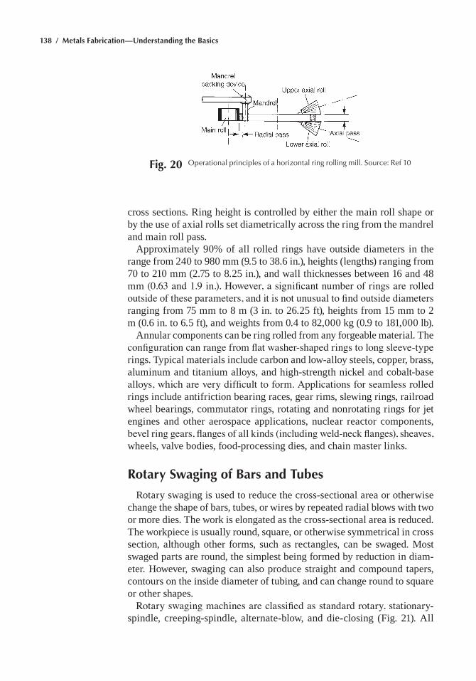
138 / Metals Fabrication—Understanding the Basics
cross sections. ring height is controlled by either the main roll shape or by the use of axial rolls set diametrically across the ring from the mandrel and main roll pass.
Approximately 90% of all rolled rings have outside diameters in the range from 240 to 980 mm (9.5 to 38.6 in.), heights (lengths) ranging from 70 to 210 mm (2.75 to 8.25 in.), and wall thicknesses between 16 and 48 mm (0.63 and 1.9 in.). However, a significant number of rings are rolled outside of these parameters, and it is not unusual to find outside diameters ranging from 75 mm to 8 m (3 in. to 26.25 ft), heights from 15 mm to 2 m (0.6 in. to 6.5 ft), and weights from 0.4 to 82,000 kg (0.9 to 181,000 lb).
Annular components can be ring rolled from any forgeable material. The configuration can range from flat washer-shaped rings to long sleeve-type rings. Typical materials include carbon and low-alloy steels, copper, brass, aluminum and titanium alloys, and high-strength nickel and cobalt-base alloys, which are very difficult to form. Applications for seamless rolled rings include antifriction bearing races, gear rims, slewing rings, railroad wheel bearings, commutator rings, rotating and nonrotating rings for jet engines and other aerospace applications, nuclear reactor components, bevel ring gears, flanges of all kinds (including weld-neck flanges), sheaves, wheels, valve bodies, food-processing dies, and chain master links.
Rotary Swaging of Bars and Tubes
rotary swaging is used to reduce the cross-sectional area or otherwise change the shape of bars, tubes, or wires by repeated radial blows with two or more dies. The work is elongated as the cross-sectional area is reduced. The workpiece is usually round, square, or otherwise symmetrical in cross section, although other forms, such as rectangles, can be swaged. most swaged parts are round, the simplest being formed by reduction in diam-eter. however, swaging can also produce straight and compound tapers, contours on the inside diameter of tubing, and can change round to square or other shapes.
Rotary swaging machines are classified as standard rotary, stationary-spindle, creeping-spindle, alternate-blow, and die-closing (Fig. 21). All
Fig. 20 Operational principles of a horizontal ring rolling mill. Source: ref 10
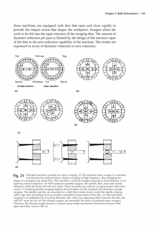
Chapter 3: Bulk Deformation / 139
Fig. 21 principle machine concepts for rotary swaging. (a) the standard rotary swager is a mechan-ical hammer that delivers blows (impact swaging) at high frequency, thus changing the
shape of a workpiece by metal flow. this machine is used for straight reducing of stock diameter or for tapering round workpieces. (b) With stationary-spindle swagers, the spindle, dies, and work remain stationary while the head and roll rack rotate. these machines are used for swaging shapes other than round. (c) Creeping-spindle swaging employs the principles of both standard and stationary-spindle swaging. the spindle and dies are mounted on a shaft that rotates slowly inside the rapidly rotating roller cage, thus permitting more accurately controlled reciprocation of the dies. (d) alternate-blow swaging is accomplished by recessing alternate rolls; when two opposing rollers hammer the dies, the rolls 90° away do not. (e) Die-closing swagers are essentially the same as standard rotary swagers. however, die-closing swagers feature a reciprocating wedge mechanism that forces closure of the taper back dies. Source: ref 10
these machines are equipped with dies that open and close rapidly to provide the impact action that shapes the workpiece. Swagers allow the work to be fed into the taper entrance of the swaging dies. The amount of diameter reduction per pass is limited by the design of the entrance taper of the dies or the area reduction capability of the machine. The results are expressed in terms of diameter reduction or area reduction.
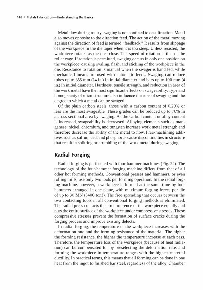
140 / Metals Fabrication—Understanding the Basics
Metal flow during rotary swaging is not confined to one direction. Metal also moves opposite to the direction feed. The action of the metal moving against the direction of feed is termed “feedback.” It results from slippage of the workpiece in the die taper when it is too steep. Unless resisted, the workpiece rotates as the dies close. The speed of rotation is that of the roller cage. If rotation is permitted, swaging occurs in only one position on the workpiece, causing ovaling, flash, and sticking of the workpiece in the die. resistance to rotation is manual when the swager is hand fed, while mechanical means are used with automatic feeds. Swaging can reduce tubes up to 355 mm (14 in.) in initial diameter and bars up to 100 mm (4 in.) in initial diameter. hardness, tensile strength, and reduction in area of the work metal have the most significant effects on swageability. Type and homogeneity of microstructure also influence the ease of swaging and the degree to which a metal can be swaged.
Of the plain carbon steels, those with a carbon content of 0.20% or less are the most swageable. These grades can be reduced up to 70% in a cross-sectional area by swaging. As the carbon content or alloy content is increased, swageability is decreased. Alloying elements such as man-ganese, nickel, chromium, and tungsten increase work metal strength and therefore decrease the ability of the metal to flow. Free-machining addi-tives such as sulfur, lead, and phosphorus cause discontinuities in structure that result in splitting or crumbling of the work metal during swaging.
Radial Forging
radial forging is performed with four-hammer machines (Fig. 22). The technology of the four-hammer forging machine differs from that of all other hot forming methods. Conventional presses and hammers, or even rolling mills, use only two tools per forming operation. In the radial forg-ing machine, however, a workpiece is formed at the same time by four hammers arranged in one plane, with maximum forging forces per die of up to 30 MN (3400 tonf). The free spreading that occurs between the two contacting tools in all conventional forging methods is eliminated. The radial press contacts the circumference of the workpiece equally and puts the entire surface of the workpiece under compressive stresses. These compressive stresses prevent the formation of surface cracks during the forging process and improve existing defects.
In radial forging, the temperature of the workpiece increases with the deformation rate and the forming resistance of the material. The higher the forming resistance, the higher the temperature increase at each pass. Therefore, the temperature loss of the workpiece (because of heat radia-tion) can be compensated for by preselecting the deformation rate, and forming the workpiece in temperature ranges with the highest material ductility. In practical terms, this means that all forming can be done in one heat from the ingot to finished bar steel, regardless of the alloy. Chamber
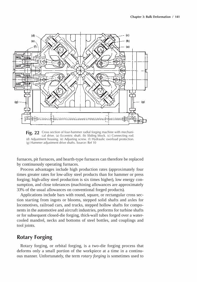
Chapter 3: Bulk Deformation / 141
furnaces, pit furnaces, and hearth-type furnaces can therefore be replaced by continuously operating furnaces.
Process advantages include high production rates (approximately four times greater rates for low-alloy steel products than for hammer or press forging; high-alloy steel production is six times higher), low energy con-sumption, and close tolerances (machining allowances are approximately 33% of the usual allowances on conventional forged products).
Applications include bars with round, square, or rectangular cross sec-tion starting from ingots or blooms, stepped solid shafts and axles for locomotives, railroad cars, and trucks, stepped hollow shafts for compo-nents in the automotive and aircraft industries, preforms for turbine shafts or for subsequent closed-die forging, thick-wall tubes forged over a water-cooled mandrel, necks and bottoms of steel bottles, and couplings and tool joints.
Rotary Forging
rotary forging, or orbital forging, is a two-die forging process that deforms only a small portion of the workpiece at a time in a continu-ous manner. Unfortunately, the term rotary forging is sometimes used to
Fig. 22 Cross section of four-hammer radial forging machine with mechani-cal drive. (a) eccentric shaft. (b) Sliding block. (c) Connecting rod.
(d) adjustment housing. (e) adjusting screw. (f) hydraulic overload protection. (g) hammer adjustment drive shafts. Source: ref 10
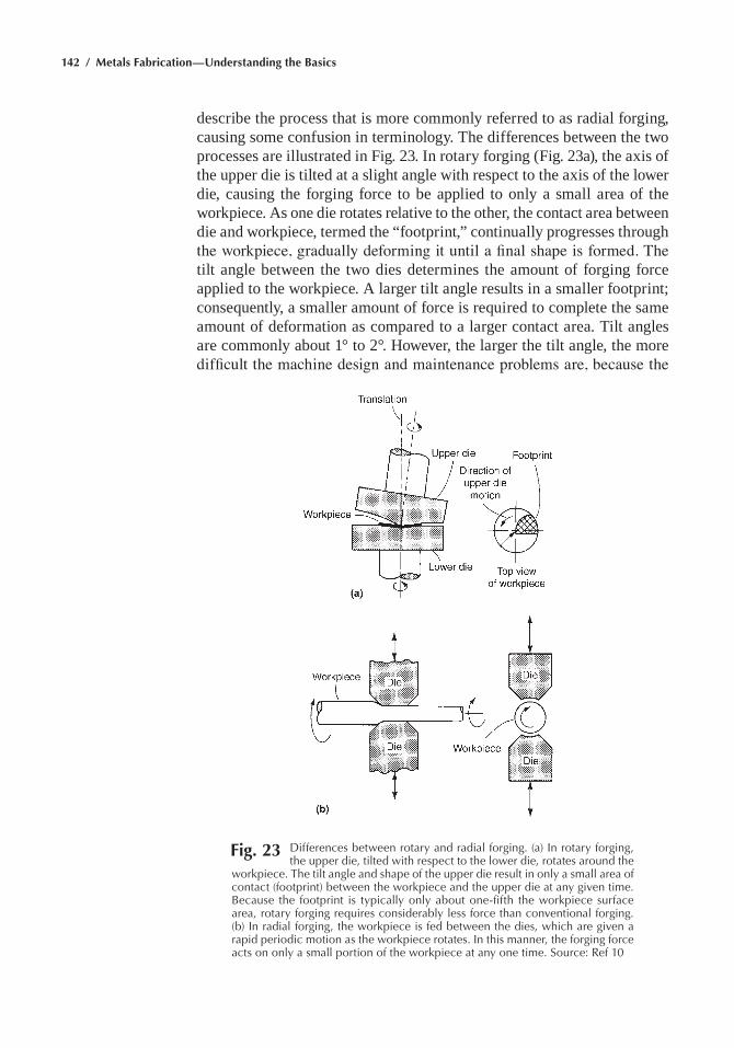
142 / Metals Fabrication—Understanding the Basics
describe the process that is more commonly referred to as radial forging, causing some confusion in terminology. The differences between the two processes are illustrated in Fig. 23. In rotary forging (Fig. 23a), the axis of the upper die is tilted at a slight angle with respect to the axis of the lower die, causing the forging force to be applied to only a small area of the workpiece. As one die rotates relative to the other, the contact area between die and workpiece, termed the “footprint,” continually progresses through the workpiece, gradually deforming it until a final shape is formed. The tilt angle between the two dies determines the amount of forging force applied to the workpiece. A larger tilt angle results in a smaller footprint; consequently, a smaller amount of force is required to complete the same amount of deformation as compared to a larger contact area. Tilt angles are commonly about 1° to 2°. however, the larger the tilt angle, the more difficult the machine design and maintenance problems are, because the
Fig. 23 Differences between rotary and radial forging. (a) In rotary forging, the upper die, tilted with respect to the lower die, rotates around the
workpiece. the tilt angle and shape of the upper die result in only a small area of contact (footprint) between the workpiece and the upper die at any given time. Because the footprint is typically only about one-fifth the workpiece surface area, rotary forging requires considerably less force than conventional forging. (b) In radial forging, the workpiece is fed between the dies, which are given a rapid periodic motion as the workpiece rotates. In this manner, the forging force acts on only a small portion of the workpiece at any one time. Source: ref 10
Chapter 3: Bulk Deformation / 143
drive and bearing system for the tilted die is subjected to large lateral loads and is more difficult to maintain. In addition, a larger tilt angle causes greater frame deflection within the forge, making it difficult to maintain a consistently high level of precision.
The primary advantage of rotary forging is in the low axial force required to form a part. Because only a small area of the die is in contact with the workpiece at any given time, rotary forging requires as little as one-tenth the force required by conventional forging techniques. The smaller forging forces reduce machine and die deformation and die-workpiece friction. This low level of equipment wear makes rotary forging a precision produc-tion process that can be used to form intricate parts to a high degree of accuracy. The average cycle time for a moderately complex part is 10 to 15 s, which is a relatively short time of deformation from preform to final part. A cycle time in the range of 10 to 15 s yields approximately 300 pieces per hour. The resulting piece is also virtually flash free. Therefore, rotary forging results in a much shorter operation from start to finish. Tooling costs for rotary forging are often lower than those for conventional forging. The smaller forging forces allow many parts to be cold forged that would conventionally require hot forging, resulting in decreased die wear and greater ease in handling parts after forging.
rotary forging is generally considered to be a substitute for conventional drop hammer or press forging. In addition, rotary forging produces parts that would otherwise have to be completely machined because of their shape or dimensions. Currently, approximately one-quarter to one-third of all parts that are either hammer or press forged could be formed on a rotary forge. Parts made by rotary forging include gears, flanges, hubs, cams, rings, and tapered rollers, as well as thin disks and flat shapes. These parts are axially symmetric and are formed by using an orbital die motion. more complex parts can be forged through the use of such rocking-die motions as straight-line, planetary, and spiral. Straight-line die motion is most commonly used to produce asymmetric pieces, such as T-flanges.
rotary forging is especially effective in forging parts that have high diameter-to-thickness ratios. Thin disks and large flanges are ideally suited to this process because of the ability of rotary forging to produce a higher ratio of lateral deformation per given downward force than conventional forging. There is also very little friction between the dies. rotary forging is also used to produce intricate features on workpiece surfaces. Parts such as gears, hubs, and hexagonal shapes have traditionally been difficult to produce by conventional forging because die-workpiece friction made it difficult to fill tight spots properly on the dies.
Any material, ferrous or nonferrous, that has adequate ductility and cold forming qualities can be rotary forged. These include carbon and alloy steels, stainless steels, brass, and aluminum alloys. In the past, cold forged production parts were primarily steels with a rockwell C hardness (hrC) in the mid 30s or lower. Generally, harder materials should be annealed
144 / Metals Fabrication—Understanding the Basics
before forging or should be warm forged. Warm rotary forging is used for materials with hrC greater than the mid 30s or when an unusually large amount of lateral movement in the workpiece is required. materials are heated to a point below their recrystallization temperature; for steels, this is generally in the range of 650 to 800 °C (1200 to 1470 °F). Because the working temperature is below the recrystallization temperature, the inherent structure and properties of the metal are preserved. Warm rotary forging increases forgeability, compared to cold rotary forging. however, some disadvantages are inherent in higher-temperature forging. The work-hardening effects on the material that are associated with cold working are not as prominent, even though the working temperature is below the recrystallization temperature. In addition, as with any forging process, higher working temperatures result in increased die wear. Dies not only wear at a faster rate but also must be fabricated from more durable, more expensive materials.
Isothermal and Hot-Die Forging
Isothermal and hot-die forging are special categories of forging processes in which the die temperatures are significantly higher than those used in conventional hot forging processes. This has the advantage of reducing die chill, thereby producing near-net and/or net shape parts. Therefore, these processes are also referred to as near-net shape forging processes. These techniques are primarily used for manufacturing airframe structures and jet engine components made of titanium and nickel-base alloys, but they have also been used in steel transmission gears and other components.
In isothermal forging, the dies are maintained at the same temperature as the forging stock. This eliminates the die chill completely and main-tains the stock at a constant temperature throughout the forging cycle. The process uses extremely slow strain rates, thus taking advantage of the strain-rate sensitivity of flow stress for certain alloys. Hot-die forging is characterized by die temperatures higher than those in conventional forging, but lower than those in isothermal forging. Typical die tempera-tures in hot-die forging are 110 to 225 °C (200 to 400 °F) lower than the temperature of the stock. When compared with isothermal forging, lower die temperature allows wider selection of die materials, but the ability to produce very thin and complex geometries is compromised. The principal criterion for selecting these processes is the economic advantage offered because of reduced input material and/or reduced machining. Therefore, they are primarily used for expensive and difficult-to-machine alloys such as titanium and nickel-base alloys.
These near-net shape processes allow the forging to be designed with smaller corner and fillet radii, a smaller draft angle, and a smaller forging envelope. These design features reduce the additional material incorpo-rated to protect the finished part geometry and therefore reduce the weight
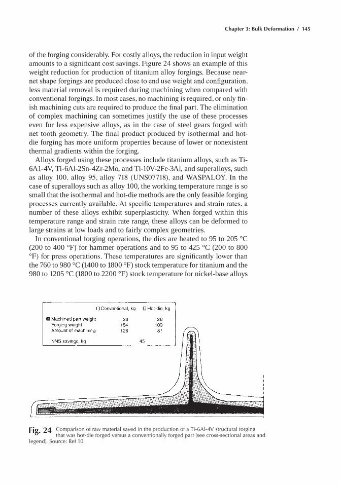
Chapter 3: Bulk Deformation / 145
of the forging considerably. For costly alloys, the reduction in input weight amounts to a significant cost savings. Figure 24 shows an example of this weight reduction for production of titanium alloy forgings. Because near-net shape forgings are produced close to end use weight and configuration, less material removal is required during machining when compared with conventional forgings. In most cases, no machining is required, or only fin-ish machining cuts are required to produce the final part. The elimination of complex machining can sometimes justify the use of these processes even for less expensive alloys, as in the case of steel gears forged with net tooth geometry. The final product produced by isothermal and hot-die forging has more uniform properties because of lower or nonexistent thermal gradients within the forging.
Alloys forged using these processes include titanium alloys, such as Ti-6A1-4V, Ti-6Al-2Sn-4Zr-2mo, and Ti-10V-2Fe-3Al, and superalloys, such as alloy 100, alloy 95, alloy 718 (UNS07718), and WASPALOY. In the case of superalloys such as alloy 100, the working temperature range is so small that the isothermal and hot-die methods are the only feasible forging processes currently available. At specific temperatures and strain rates, a number of these alloys exhibit superplasticity. When forged within this temperature range and strain rate range, these alloys can be deformed to large strains at low loads and to fairly complex geometries.
In conventional forging operations, the dies are heated to 95 to 205 °C (200 to 400 °F) for hammer operations and to 95 to 425 °C (200 to 800 °F) for press operations. These temperatures are significantly lower than the 760 to 980 °C (1400 to 1800 °F) stock temperature for titanium and the 980 to 1205 °C (1800 to 2200 °F) stock temperature for nickel-base alloys
Fig. 24 Comparison of raw material saved in the production of a ti-6al-4V structural forging that was hot-die forged versus a conventionally forged part (see cross-sectional areas and
legend). Source: ref 10
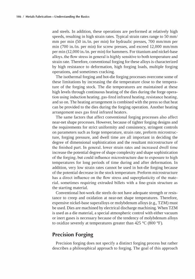
146 / Metals Fabrication—Understanding the Basics
and steels. In addition, these operations are performed at relatively high speeds, resulting in high strain rates. Typical strain rates range to 50 mm/mm per min (50 in./in. per min) for hydraulic presses, 700 mm/mm per min (700 in./in. per min) for screw presses, and exceed 12,000 mm/mm per min (12,000 in./in. per min) for hammers. For titanium and nickel-base alloys, the flow stress in general is highly sensitive to both temperature and strain rate. Therefore, conventional forging for these alloys is characterized by high resistance to deformation, high forging loads, multiple forging operations, and sometimes cracking.
The isothermal forging and hot-die forging processes overcome some of these limitations by increasing the die temperature close to the tempera-ture of the forging stock. The die temperatures are maintained at these high levels through continuous heating of the dies during the forge opera-tion using induction heating, gas-fired infrared heating, resistance heating, and so on. The heating arrangement is combined with the press so that heat can be provided to the dies during the forging operation. Another heating arrangement uses gas fired infrared heaters.
The same factors that affect conventional forging processes also affect near-net shape processes. however, because of tighter forging designs and the requirements for strict uniformity and consistency, stringent controls on parameters such as forge temperature, strain rate, preform microstruc-ture, forging pressure, and dwell time are all important in deciding the degree of dimensional sophistication and the resultant microstructure of the finished part. In general, lower strain rates and increased dwell time increase the potential degree of shape complexity and shape sophistication of the forging, but could influence microstructure due to exposure to high temperatures for long periods of time during and after deformation. In addition, very low strain rates cannot be used in hot-die forging because of the potential decrease in the stock temperature. Preform microstructure has a direct influence on the flow stress and superplasticity of the mate-rial, sometimes requiring extruded billets with a fine-grain structure as the starting material.
Conventional hot-work die steels do not have adequate strength or resis-tance to creep and oxidation at near-net shape temperatures. Therefore, expensive nickel-base superalloys or molybdenum alloys (e.g., TZm) must be used. Dies are machined by electrical discharge machining. When TZm is used as a die material, a special atmospheric control with either vacuum or inert gases is necessary because of the tendency of molybdenum alloys to oxidize severely at temperatures greater than 425 °C (800 °F).
Precision Forging
Precision forging does not specify a distinct forging process but rather describes a philosophical approach to forging. The goal of this approach
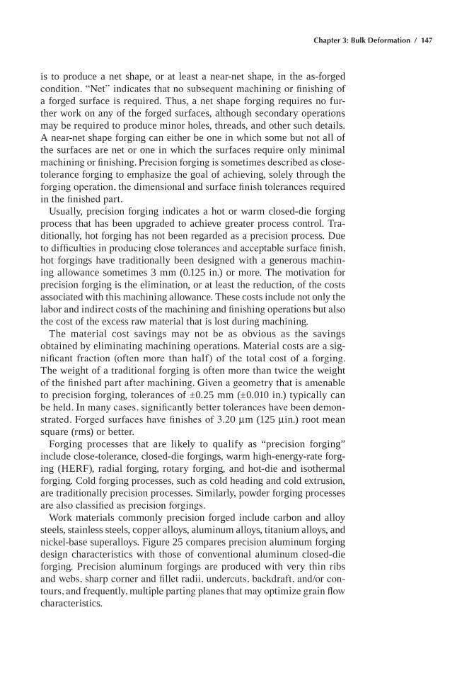
Chapter 3: Bulk Deformation / 147
is to produce a net shape, or at least a near-net shape, in the as-forged condition. “Net” indicates that no subsequent machining or finishing of a forged surface is required. Thus, a net shape forging requires no fur-ther work on any of the forged surfaces, although secondary operations may be required to produce minor holes, threads, and other such details. A near-net shape forging can either be one in which some but not all of the surfaces are net or one in which the surfaces require only minimal machining or finishing. Precision forging is sometimes described as close-tolerance forging to emphasize the goal of achieving, solely through the forging operation, the dimensional and surface finish tolerances required in the finished part.
Usually, precision forging indicates a hot or warm closed-die forging process that has been upgraded to achieve greater process control. Tra-ditionally, hot forging has not been regarded as a precision process. Due to difficulties in producing close tolerances and acceptable surface finish, hot forgings have traditionally been designed with a generous machin-ing allowance sometimes 3 mm (0.125 in.) or more. The motivation for precision forging is the elimination, or at least the reduction, of the costs associated with this machining allowance. These costs include not only the labor and indirect costs of the machining and finishing operations but also the cost of the excess raw material that is lost during machining.
The material cost savings may not be as obvious as the savings obtained by eliminating machining operations. material costs are a sig-nificant fraction (often more than half) of the total cost of a forging. The weight of a traditional forging is often more than twice the weight of the finished part after machining. Given a geometry that is amenable to precision forging, tolerances of ±0.25 mm (±0.010 in.) typically can be held. In many cases, significantly better tolerances have been demon-strated. Forged surfaces have finishes of 3.20 mm (125 min.) root mean square (rms) or better.
Forging processes that are likely to qualify as “precision forging” include close-tolerance, closed-die forgings, warm high-energy-rate forg-ing (herF), radial forging, rotary forging, and hot-die and isothermal forging. Cold forging processes, such as cold heading and cold extrusion, are traditionally precision processes. Similarly, powder forging processes are also classified as precision forgings.
Work materials commonly precision forged include carbon and alloy steels, stainless steels, copper alloys, aluminum alloys, titanium alloys, and nickel-base superalloys. Figure 25 compares precision aluminum forging design characteristics with those of conventional aluminum closed-die forging. Precision aluminum forgings are produced with very thin ribs and webs, sharp corner and fillet radii, undercuts, backdraft, and/or con-tours, and frequently, multiple parting planes that may optimize grain flow characteristics.
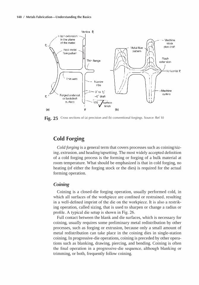
148 / Metals Fabrication—Understanding the Basics
Cold Forging
Cold forging is a general term that covers processes such as coining/siz-ing, extrusion, and heading/upsetting. The most widely accepted definition of a cold forging process is the forming or forging of a bulk material at room temperature. What should be emphasized is that in cold forging, no heating (of either the forging stock or the dies) is required for the actual forming operation.
Coining
Coining is a closed-die forging operation, usually performed cold, in which all surfaces of the workpiece are confined or restrained, resulting in a well-defined imprint of the die on the workpiece. It is also a restrik-ing operation, called sizing, that is used to sharpen or change a radius or profile. A typical die setup is shown in Fig. 26.
Full contact between the blank and die surfaces, which is necessary for coining, usually requires some preliminary metal redistribution by other processes, such as forging or extrusion, because only a small amount of metal redistribution can take place in the coining dies in single-station coining. In progressive-die operations, coining is preceded by other opera-tions such as blanking, drawing, piercing, and bending. Coining is often the final operation in a progressive-die sequence, although blanking or trimming, or both, frequently follow coining.
Fig. 25 Cross sections of (a) precision and (b) conventional forgings. Source: ref 10
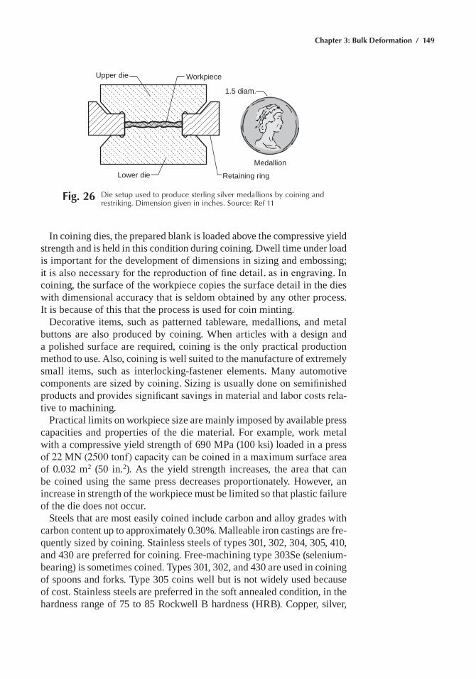
Chapter 3: Bulk Deformation / 149
In coining dies, the prepared blank is loaded above the compressive yield strength and is held in this condition during coining. Dwell time under load is important for the development of dimensions in sizing and embossing; it is also necessary for the reproduction of fine detail, as in engraving. In coining, the surface of the workpiece copies the surface detail in the dies with dimensional accuracy that is seldom obtained by any other process. It is because of this that the process is used for coin minting.
Decorative items, such as patterned tableware, medallions, and metal buttons are also produced by coining. When articles with a design and a polished surface are required, coining is the only practical production method to use. Also, coining is well suited to the manufacture of extremely small items, such as interlocking-fastener elements. many automotive components are sized by coining. Sizing is usually done on semifinished products and provides significant savings in material and labor costs rela-tive to machining.
Practical limits on workpiece size are mainly imposed by available press capacities and properties of the die material. For example, work metal with a compressive yield strength of 690 mPa (100 ksi) loaded in a press of 22 MN (2500 tonf) capacity can be coined in a maximum surface area of 0.032 m2 (50 in.2). As the yield strength increases, the area that can be coined using the same press decreases proportionately. however, an increase in strength of the workpiece must be limited so that plastic failure of the die does not occur.
Steels that are most easily coined include carbon and alloy grades with carbon content up to approximately 0.30%. malleable iron castings are fre-quently sized by coining. Stainless steels of types 301, 302, 304, 305, 410, and 430 are preferred for coining. Free-machining type 303Se (selenium-bearing) is sometimes coined. Types 301, 302, and 430 are used in coining of spoons and forks. Type 305 coins well but is not widely used because of cost. Stainless steels are preferred in the soft annealed condition, in the hardness range of 75 to 85 rockwell B hardness (hrB). Copper, silver,
WorkpieceUpper die
Lower die Retaining ring
Medallion
1.5 diam.
Fig. 26 Die setup used to produce sterling silver medallions by coining and restriking. Dimension given in inches. Source: ref 11
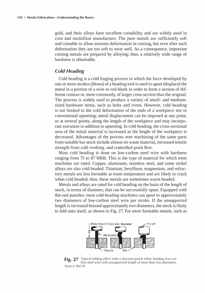
150 / Metals Fabrication—Understanding the Basics
gold, and their alloys have excellent coinability and are widely used in coin and medallion manufacture. The pure metals are sufficiently soft and coinable to allow extreme deformation in coining, but even after such deformation they are too soft to wear well. As a consequence, important coining metals are prepared by alloying; thus, a relatively wide range of hardness is obtainable.
Cold Heading
Cold heading is a cold forging process in which the force developed by one or more strokes (blows) of a heading tool is used to upset (displace) the metal in a portion of a wire or rod blank in order to form a section of dif-ferent contour or, more commonly, of larger cross section than the original. The process is widely used to produce a variety of small- and medium-sized hardware items, such as bolts and rivets. however, cold heading is not limited to the cold deformation of the ends of a workpiece nor to conventional upsetting; metal displacement can be imposed at any point, or at several points, along the length of the workpiece and may incorpo-rate extrusion in addition to upsetting. In cold heading, the cross-sectional area of the initial material is increased as the height of the workpiece is decreased. Advantages of the process over machining of the same parts from suitable bar stock include almost no waste material, increased tensile strength from cold working, and controlled grain flow.
most cold heading is done on low-carbon steel wire with hardness ranging from 75 to 87 hrB. This is the type of material for which most machines are rated. Copper, aluminum, stainless steel, and some nickel alloys are also cold headed. Titanium, beryllium, magnesium, and refrac-tory metals are less formable at room temperature and are likely to crack when cold headed; thus, these metals are sometimes warm headed.
metals and alloys are rated for cold heading on the basis of the length of stock, in terms of diameter, that can be successfully upset. equipped with flat-end punches, most cold-heading machines can upset to approximately two diameters of low-carbon steel wire per stroke. If the unsupported length is increased beyond approximately two diameters, the stock is likely to fold onto itself, as shown in Fig. 27. For more formable metals, such as
Fig. 27 typical folding effect with a flat-end punch when heading low-car-bon steel wire with unsupported length of more than two diameters.
Source: ref 10
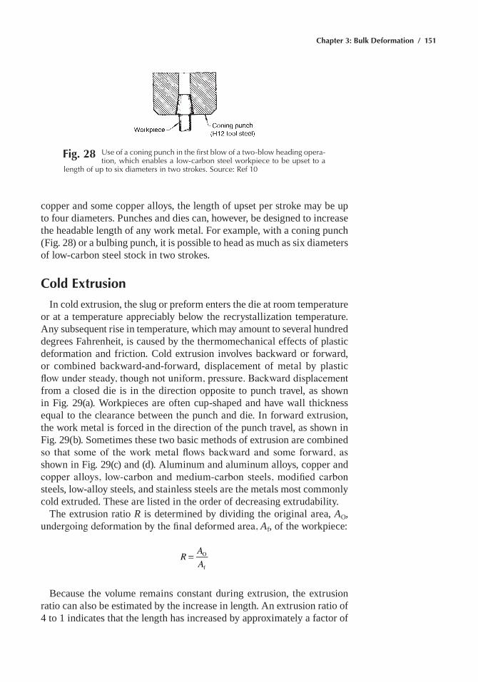
Chapter 3: Bulk Deformation / 151
copper and some copper alloys, the length of upset per stroke may be up to four diameters. Punches and dies can, however, be designed to increase the headable length of any work metal. For example, with a coning punch (Fig. 28) or a bulbing punch, it is possible to head as much as six diameters of low-carbon steel stock in two strokes.
Cold Extrusion
In cold extrusion, the slug or preform enters the die at room temperature or at a temperature appreciably below the recrystallization temperature. Any subsequent rise in temperature, which may amount to several hundred degrees Fahrenheit, is caused by the thermomechanical effects of plastic deformation and friction. Cold extrusion involves backward or forward, or combined backward-and-forward, displacement of metal by plastic flow under steady, though not uniform, pressure. Backward displacement from a closed die is in the direction opposite to punch travel, as shown in Fig. 29(a). Workpieces are often cup-shaped and have wall thickness equal to the clearance between the punch and die. In forward extrusion, the work metal is forced in the direction of the punch travel, as shown in Fig. 29(b). Sometimes these two basic methods of extrusion are combined so that some of the work metal flows backward and some forward, as shown in Fig. 29(c) and (d). Aluminum and aluminum alloys, copper and copper alloys, low-carbon and medium-carbon steels, modified carbon steels, low-alloy steels, and stainless steels are the metals most commonly cold extruded. These are listed in the order of decreasing extrudability.
The extrusion ratio R is determined by dividing the original area, AO, undergoing deformation by the final deformed area, Af, of the workpiece:
=R AA
O
f
Because the volume remains constant during extrusion, the extrusion ratio can also be estimated by the increase in length. An extrusion ratio of 4 to 1 indicates that the length has increased by approximately a factor of
Fig. 28 Use of a coning punch in the first blow of a two-blow heading opera-tion, which enables a low-carbon steel workpiece to be upset to a
length of up to six diameters in two strokes. Source: ref 10
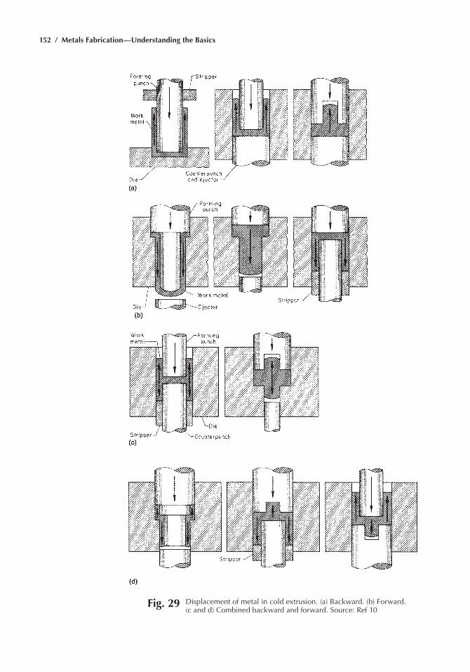
152 / Metals Fabrication—Understanding the Basics
Fig. 29 Displacement of metal in cold extrusion. (a) Backward. (b) Forward. (c and d) Combined backward and forward. Source: ref 10
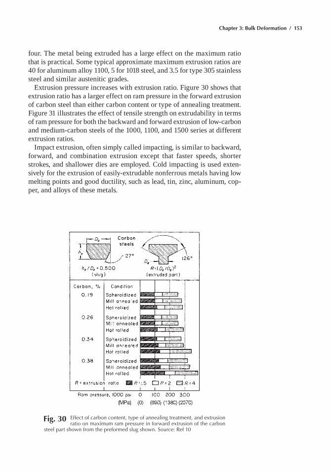
Chapter 3: Bulk Deformation / 153
four. The metal being extruded has a large effect on the maximum ratio that is practical. Some typical approximate maximum extrusion ratios are 40 for aluminum alloy 1100, 5 for 1018 steel, and 3.5 for type 305 stainless steel and similar austenitic grades.
extrusion pressure increases with extrusion ratio. Figure 30 shows that extrusion ratio has a larger effect on ram pressure in the forward extrusion of carbon steel than either carbon content or type of annealing treatment. Figure 31 illustrates the effect of tensile strength on extrudability in terms of ram pressure for both the backward and forward extrusion of low-carbon and medium-carbon steels of the 1000, 1100, and 1500 series at different extrusion ratios.
Impact extrusion, often simply called impacting, is similar to backward, forward, and combination extrusion except that faster speeds, shorter strokes, and shallower dies are employed. Cold impacting is used exten-sively for the extrusion of easily-extrudable nonferrous metals having low melting points and good ductility, such as lead, tin, zinc, aluminum, cop-per, and alloys of these metals.
Fig. 30 effect of carbon content, type of annealing treatment, and extrusion ratio on maximum ram pressure in forward extrusion of the carbon
steel part shown from the preformed slug shown. Source: ref 10
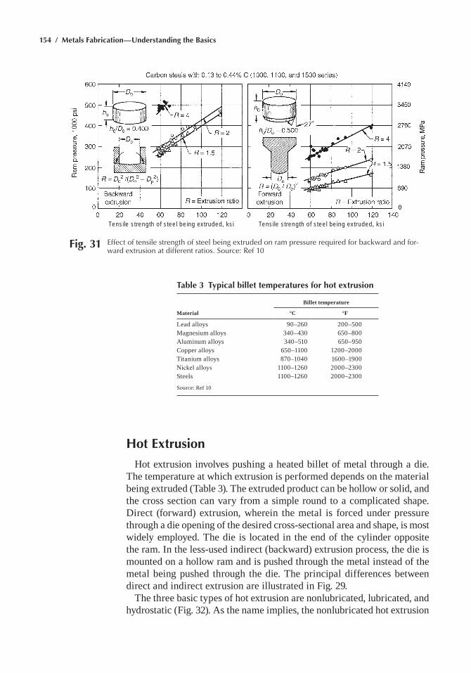
154 / Metals Fabrication—Understanding the Basics
Hot Extrusion
hot extrusion involves pushing a heated billet of metal through a die. The temperature at which extrusion is performed depends on the material being extruded (Table 3). The extruded product can be hollow or solid, and the cross section can vary from a simple round to a complicated shape. Direct (forward) extrusion, wherein the metal is forced under pressure through a die opening of the desired cross-sectional area and shape, is most widely employed. The die is located in the end of the cylinder opposite the ram. In the less-used indirect (backward) extrusion process, the die is mounted on a hollow ram and is pushed through the metal instead of the metal being pushed through the die. The principal differences between direct and indirect extrusion are illustrated in Fig. 29.
The three basic types of hot extrusion are nonlubricated, lubricated, and hydrostatic (Fig. 32). As the name implies, the nonlubricated hot extrusion
Tensile strength of steel being extruded, ksi Tensile strength of steel being extruded, ksi
Fig. 31 effect of tensile strength of steel being extruded on ram pressure required for backward and for-ward extrusion at different ratios. Source: ref 10
Table 3 Typical billet temperatures for hot extrusion
Billet temperature
Material °C °F
Lead alloys 90–260 200–500magnesium alloys 340–430 650–800Aluminum alloys 340–510 650–950Copper alloys 650–1100 1200–2000Titanium alloys 870–1040 1600–1900Nickel alloys 1100–1260 2000–2300Steels 1100–1260 2000–2300
Source: ref 10
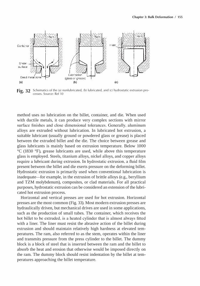
Chapter 3: Bulk Deformation / 155
method uses no lubrication on the billet, container, and die. When used with ductile metals, it can produce very complex sections with mirror surface finishes and close dimensional tolerances. Generally, aluminum alloys are extruded without lubrication. In lubricated hot extrusion, a suitable lubricant (usually ground or powdered glass or grease) is placed between the extruded billet and the die. The choice between grease and glass lubricants is mainly based on extrusion temperature. Below 1000 °C (1830 °F), grease lubricants are used, while above this temperature glass is employed. Steels, titanium alloys, nickel alloys, and copper alloys require a lubricant during extrusion. In hydrostatic extrusion, a fluid film present between the billet and die exerts pressure on the deforming billet. hydrostatic extrusion is primarily used when conventional lubrication is inadequate—for example, in the extrusion of brittle alloys (e.g., beryllium and TZm molybdenum), composites, or clad materials. For all practical purposes, hydrostatic extrusion can be considered an extension of the lubri-cated hot extrusion process.
horizontal and vertical presses are used for hot extrusion. horizontal presses are the most common (Fig. 33). most modern extrusion presses are hydraulically driven, but mechanical drives are used in some applications, such as the production of small tubes. The container, which receives the hot billet to be extruded, is a heated cylinder that is almost always fitted with a liner. The liner must resist the abrasive action of the billet during extrusion and should maintain relatively high hardness at elevated tem-peratures. The ram, also referred to as the stem, operates within the liner and transmits pressure from the press cylinder to the billet. The dummy block is a block of steel that is inserted between the ram and the billet to absorb the heat and erosion that otherwise would be imposed directly on the ram. The dummy block should resist indentation by the billet at tem-peratures approaching the billet temperature.
Fig. 32 Schematics of the (a) nonlubricated, (b) lubricated, and (c) hydrostatic extrusion pro-cesses. Source: ref 10
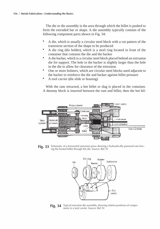
156 / Metals Fabrication—Understanding the Basics
The die or die assembly is the area through which the billet is pushed to form the extruded bar or shape. A die assembly typically consists of the following component parts shown in Fig. 34:
• A die, which is usually a circular steel block with a cut pattern of the transverse section of the shape to be produced
• A die ring (die holder), which is a steel ring located in front of the container that contains the die and the backer
• A die backer, which is a circular steel block placed behind an extrusion die for support. The hole in the backer is slightly larger than the hole in the die to allow for clearance of the extrusion.
• One or more bolsters, which are circular steel blocks used adjacent to the backer to reinforce the die and backer against billet pressure
• A tool carrier (die slide or housing)
With the ram retracted, a hot billet or slug is placed in the container. A dummy block is inserted between the ram and billet; then the hot bil-
Fig. 33 Schematic of a horizontal extrusion press showing a hydraulically powered ram forc-ing the heated billet through the die. Source: ref 10
Fig. 34 typical extrusion die assembly, showing relative positions of compo-nents in a tool carrier. Source: ref 10
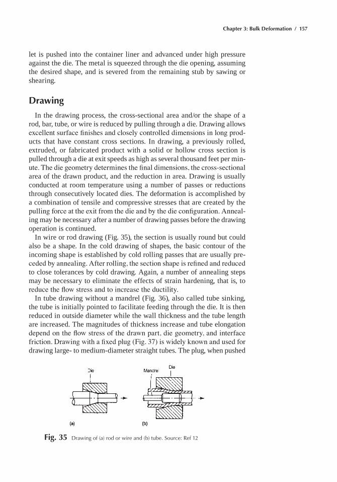
Chapter 3: Bulk Deformation / 157
let is pushed into the container liner and advanced under high pressure against the die. The metal is squeezed through the die opening, assuming the desired shape, and is severed from the remaining stub by sawing or shearing.
Drawing
In the drawing process, the cross-sectional area and/or the shape of a rod, bar, tube, or wire is reduced by pulling through a die. Drawing allows excellent surface finishes and closely controlled dimensions in long prod-ucts that have constant cross sections. In drawing, a previously rolled, extruded, or fabricated product with a solid or hollow cross section is pulled through a die at exit speeds as high as several thousand feet per min-ute. The die geometry determines the final dimensions, the cross-sectional area of the drawn product, and the reduction in area. Drawing is usually conducted at room temperature using a number of passes or reductions through consecutively located dies. The deformation is accomplished by a combination of tensile and compressive stresses that are created by the pulling force at the exit from the die and by the die configuration. Anneal-ing may be necessary after a number of drawing passes before the drawing operation is continued.
In wire or rod drawing (Fig. 35), the section is usually round but could also be a shape. In the cold drawing of shapes, the basic contour of the incoming shape is established by cold rolling passes that are usually pre-ceded by annealing. After rolling, the section shape is refined and reduced to close tolerances by cold drawing. Again, a number of annealing steps may be necessary to eliminate the effects of strain hardening, that is, to reduce the flow stress and to increase the ductility.
In tube drawing without a mandrel (Fig. 36), also called tube sinking, the tube is initially pointed to facilitate feeding through the die. It is then reduced in outside diameter while the wall thickness and the tube length are increased. The magnitudes of thickness increase and tube elongation depend on the flow stress of the drawn part, die geometry, and interface friction. Drawing with a fixed plug (Fig. 37) is widely known and used for drawing large- to medium-diameter straight tubes. The plug, when pushed
Fig. 35 Drawing of (a) rod or wire and (b) tube. Source: ref 12
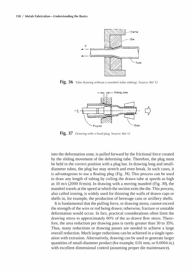
158 / Metals Fabrication—Understanding the Basics
into the deformation zone, is pulled forward by the frictional force created by the sliding movement of the deforming tube. Therefore, the plug must be held in the correct position with a plug bar. In drawing long and small-diameter tubes, the plug bar may stretch and even break. In such cases, it is advantageous to use a floating plug (Fig. 38). This process can be used to draw any length of tubing by coiling the drawn tube at speeds as high as 10 m/s (2000 ft/min). In drawing with a moving mandrel (Fig. 39), the mandrel travels at the speed at which the section exits the die. This process, also called ironing, is widely used for thinning the walls of drawn cups or shells in, for example, the production of beverage cans or artillery shells.
It is fundamental that the pulling force, or drawing stress, cannot exceed the strength of the wire or rod being drawn; otherwise, fracture or unstable deformation would occur. In fact, practical considerations often limit the drawing stress to approximately 60% of the as-drawn flow stress. There-fore, the area reduction per drawing pass is rarely greater than 30 to 35%. Thus, many reductions or drawing passes are needed to achieve a large overall reduction. much larger reductions can be achieved in a single oper-ation with extrusion. Alternatively, drawing can be used to generate larger quantities of small-diameter product (for example, 0.01 mm, or 0.0004 in.) with excellent dimensional control (assuming proper die maintenance).
Fig. 36 tube drawing without a mandrel (tube sinking). Source: ref 12
Fig. 37 Drawing with a fixed plug. Source: ref 12
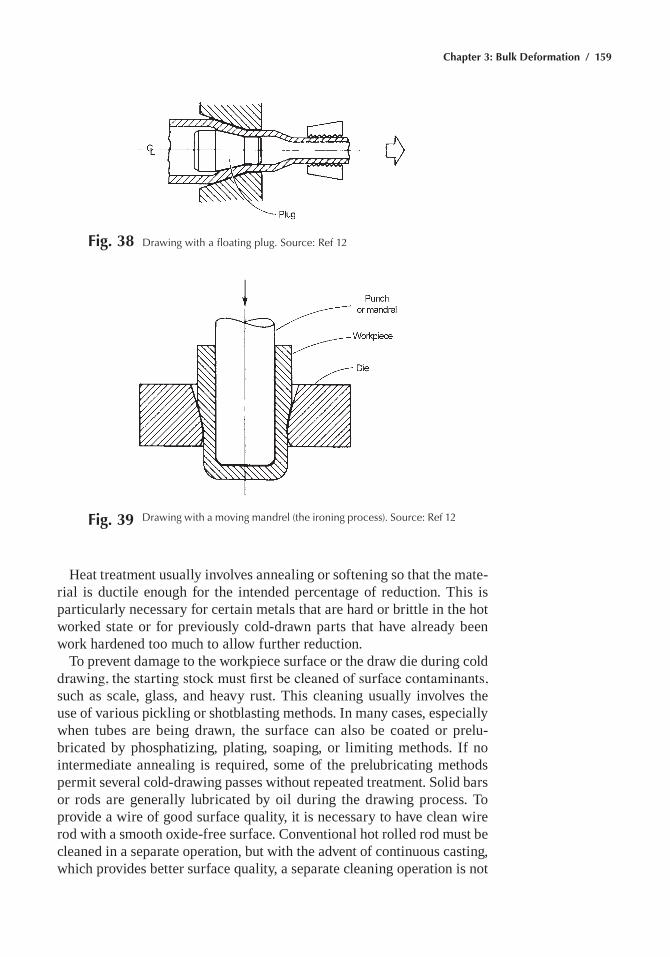
Chapter 3: Bulk Deformation / 159
heat treatment usually involves annealing or softening so that the mate-rial is ductile enough for the intended percentage of reduction. This is particularly necessary for certain metals that are hard or brittle in the hot worked state or for previously cold-drawn parts that have already been work hardened too much to allow further reduction.
To prevent damage to the workpiece surface or the draw die during cold drawing, the starting stock must first be cleaned of surface contaminants, such as scale, glass, and heavy rust. This cleaning usually involves the use of various pickling or shotblasting methods. In many cases, especially when tubes are being drawn, the surface can also be coated or prelu-bricated by phosphatizing, plating, soaping, or limiting methods. If no intermediate annealing is required, some of the prelubricating methods permit several cold-drawing passes without repeated treatment. Solid bars or rods are generally lubricated by oil during the drawing process. To provide a wire of good surface quality, it is necessary to have clean wire rod with a smooth oxide-free surface. Conventional hot rolled rod must be cleaned in a separate operation, but with the advent of continuous casting, which provides better surface quality, a separate cleaning operation is not
Fig. 38 Drawing with a floating plug. Source: ref 12
Fig. 39 Drawing with a moving mandrel (the ironing process). Source: ref 12
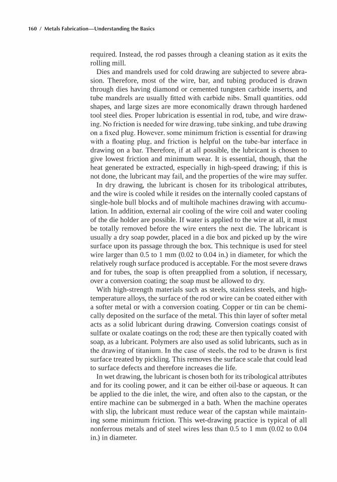
160 / Metals Fabrication—Understanding the Basics
required. Instead, the rod passes through a cleaning station as it exits the rolling mill.
Dies and mandrels used for cold drawing are subjected to severe abra-sion. Therefore, most of the wire, bar, and tubing produced is drawn through dies having diamond or cemented tungsten carbide inserts, and tube mandrels are usually fitted with carbide nibs. Small quantities, odd shapes, and large sizes are more economically drawn through hardened tool steel dies. Proper lubrication is essential in rod, tube, and wire draw-ing. No friction is needed for wire drawing, tube sinking, and tube drawing on a fixed plug. However, some minimum friction is essential for drawing with a floating plug, and friction is helpful on the tube-bar interface in drawing on a bar. Therefore, if at all possible, the lubricant is chosen to give lowest friction and minimum wear. It is essential, though, that the heat generated be extracted, especially in high-speed drawing; if this is not done, the lubricant may fail, and the properties of the wire may suffer.
In dry drawing, the lubricant is chosen for its tribological attributes, and the wire is cooled while it resides on the internally cooled capstans of single-hole bull blocks and of multihole machines drawing with accumu-lation. In addition, external air cooling of the wire coil and water cooling of the die holder are possible. If water is applied to the wire at all, it must be totally removed before the wire enters the next die. The lubricant is usually a dry soap powder, placed in a die box and picked up by the wire surface upon its passage through the box. This technique is used for steel wire larger than 0.5 to 1 mm (0.02 to 0.04 in.) in diameter, for which the relatively rough surface produced is acceptable. For the most severe draws and for tubes, the soap is often preapplied from a solution, if necessary, over a conversion coating; the soap must be allowed to dry.
With high-strength materials such as steels, stainless steels, and high-temperature alloys, the surface of the rod or wire can be coated either with a softer metal or with a conversion coating. Copper or tin can be chemi-cally deposited on the surface of the metal. This thin layer of softer metal acts as a solid lubricant during drawing. Conversion coatings consist of sulfate or oxalate coatings on the rod; these are then typically coated with soap, as a lubricant. Polymers are also used as solid lubricants, such as in the drawing of titanium. In the case of steels, the rod to be drawn is first surface treated by pickling. This removes the surface scale that could lead to surface defects and therefore increases die life.
In wet drawing, the lubricant is chosen both for its tribological attributes and for its cooling power, and it can be either oil-base or aqueous. It can be applied to the die inlet, the wire, and often also to the capstan, or the entire machine can be submerged in a bath. When the machine operates with slip, the lubricant must reduce wear of the capstan while maintain-ing some minimum friction. This wet-drawing practice is typical of all nonferrous metals and of steel wires less than 0.5 to 1 mm (0.02 to 0.04 in.) in diameter.
Chapter 3: Bulk Deformation / 161
ACKNOWLEDGMENT
This chapter was adapted from Forging in Metals Handbook Desk Edi-tion, 2nd ed., ASm International, 1998.
REFERENCES
1. J. Beddoes and m.J. Bibby, Principles of Metal Manufacturing Pro-cesses, Arnold, 1999
2. F.C. Campbell, Elements of Metallurgy and Engineering Alloys, ASm, 2008
3. G.e. Dieter, Introduction to Workability, Forming and Forging, Vol 14, ASM Handbook, ASm International, 1988
4. S. Kalpakjian, mechanical Testing for metalworking Processes, Mechanical Testing and Evaluation, Vol 8, ASM Handbook, ASm International, 2000
5. Forging of Carbon and Alloy Steels, Forming and Forging, Vol 14, ASM Handbook, ASm International, 1988
6. hammers and Presses for Forging, Metals Handbook Desk Edition, 2nd ed., ASm International, 1998
7. Die Design and materials, Metals Handbook Desk Edition, 2nd ed., ASm International, 1998
8. Failures related to metalworking, Failure Analysis and Prevention, Vol 11, ASM Handbook, ASm International, 2002
9. T. Altan, G. Ngaile, and G. Shen, Cold and Hot Forging: Fundamen-tals and Applications, ASm International, 2005
10. Forging Processes, Metals Handbook Desk Edition, 2nd ed., ASm International, 1998
11. Coining, Forming and Forging, Vol 14, ASM Handbook, ASm Inter-national, 1988
12. Forming of Bars, Tube, and Wire, Metals Handbook Desk Edition, 2nd ed., ASm International, 1998
SELECTED REFERENCES• T. Altan et al., ed., Forging Equipment, Materials, and Practices,
Battelle-Columbus Laboratories, metalworking Division, 1973• m. Bauser, G. Sauer, and K. Siegert, Extrusion, 2nd ed., ASm Inter-
national, 2006• T.G. Byrer, ed., Forging Handbook, Forging Industry Association and
American Society for metals, 1984• D. Lange, ed., Handbook of Metal Forming, mcGraw-hill, 1985• Open Die Forging Manual, 3rd ed., Forging Institute of America, 1992
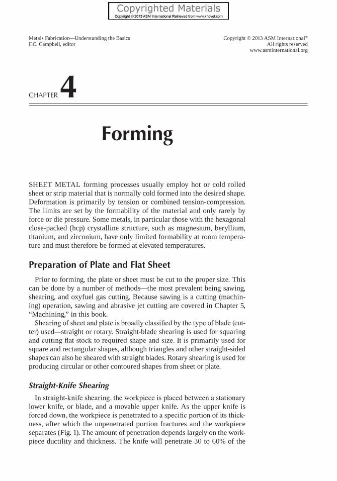
Copyright © 2013 ASM International®
All rights reservedwww.asminternational.org
Metals Fabrication—Understanding the BasicsF.C. Campbell, editor
Chapter 4Forming
Sheet metal forming processes usually employ hot or cold rolled sheet or strip material that is normally cold formed into the desired shape. Deformation is primarily by tension or combined tension-compression. the limits are set by the formability of the material and only rarely by force or die pressure. Some metals, in particular those with the hexagonal close-packed (hcp) crystalline structure, such as magnesium, beryllium, titanium, and zirconium, have only limited formability at room tempera-ture and must therefore be formed at elevated temperatures.
Preparation of Plate and Flat Sheet
Prior to forming, the plate or sheet must be cut to the proper size. this can be done by a number of methods—the most prevalent being sawing, shearing, and oxyfuel gas cutting. Because sawing is a cutting (machin-ing) operation, sawing and abrasive jet cutting are covered in Chapter 5, “machining,” in this book.
Shearing of sheet and plate is broadly classified by the type of blade (cut-ter) used—straight or rotary. Straight-blade shearing is used for squaring and cutting flat stock to required shape and size. It is primarily used for square and rectangular shapes, although triangles and other straight-sided shapes can also be sheared with straight blades. Rotary shearing is used for producing circular or other contoured shapes from sheet or plate.
Straight-Knife Shearing
In straight-knife shearing, the workpiece is placed between a stationary lower knife, or blade, and a movable upper knife. as the upper knife is forced down, the workpiece is penetrated to a specific portion of its thick-ness, after which the unpenetrated portion fractures and the workpiece separates (Fig. 1). the amount of penetration depends largely on the work-piece ductility and thickness. the knife will penetrate 30 to 60% of the
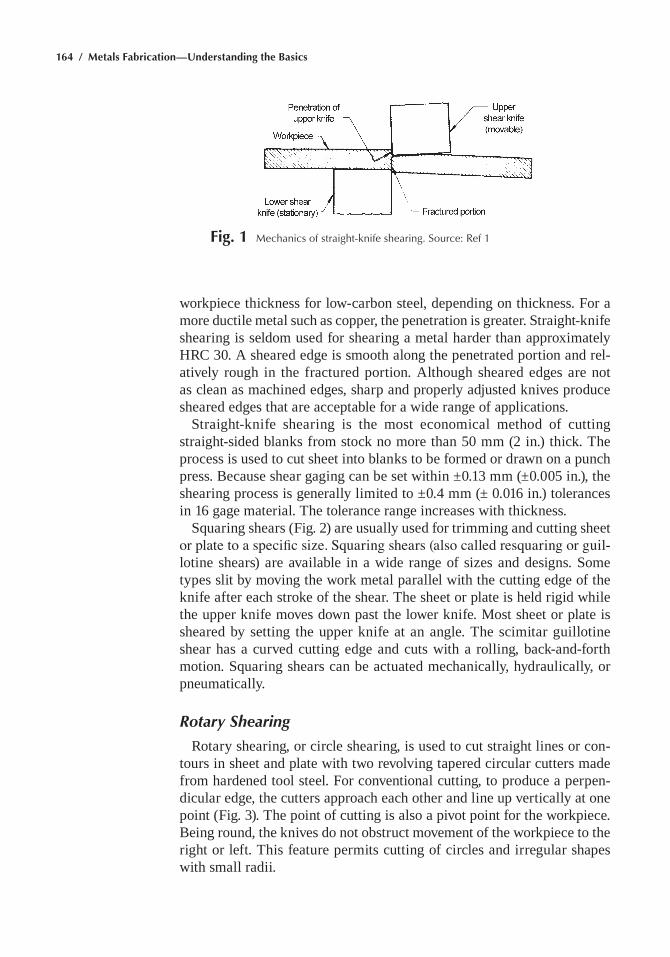
164 / Metals Fabrication—Understanding the Basics
Fig. 1 Mechanics of straight-knife shearing. Source: ref 1
workpiece thickness for low-carbon steel, depending on thickness. For a more ductile metal such as copper, the penetration is greater. Straight-knife shearing is seldom used for shearing a metal harder than approximately hRC 30. a sheared edge is smooth along the penetrated portion and rel-atively rough in the fractured portion. although sheared edges are not as clean as machined edges, sharp and properly adjusted knives produce sheared edges that are acceptable for a wide range of applications.
Straight-knife shearing is the most economical method of cutting straight-sided blanks from stock no more than 50 mm (2 in.) thick. the process is used to cut sheet into blanks to be formed or drawn on a punch press. Because shear gaging can be set within ±0.13 mm (±0.005 in.), the shearing process is generally limited to ±0.4 mm (± 0.016 in.) tolerances in 16 gage material. the tolerance range increases with thickness.
Squaring shears (Fig. 2) are usually used for trimming and cutting sheet or plate to a specific size. Squaring shears (also called resquaring or guil-lotine shears) are available in a wide range of sizes and designs. Some types slit by moving the work metal parallel with the cutting edge of the knife after each stroke of the shear. the sheet or plate is held rigid while the upper knife moves down past the lower knife. most sheet or plate is sheared by setting the upper knife at an angle. the scimitar guillotine shear has a curved cutting edge and cuts with a rolling, back-and-forth motion. Squaring shears can be actuated mechanically, hydraulically, or pneumatically.
Rotary Shearing
Rotary shearing, or circle shearing, is used to cut straight lines or con-tours in sheet and plate with two revolving tapered circular cutters made from hardened tool steel. For conventional cutting, to produce a perpen-dicular edge, the cutters approach each other and line up vertically at one point (Fig. 3). the point of cutting is also a pivot point for the workpiece. Being round, the knives do not obstruct movement of the workpiece to the right or left. this feature permits cutting of circles and irregular shapes with small radii.
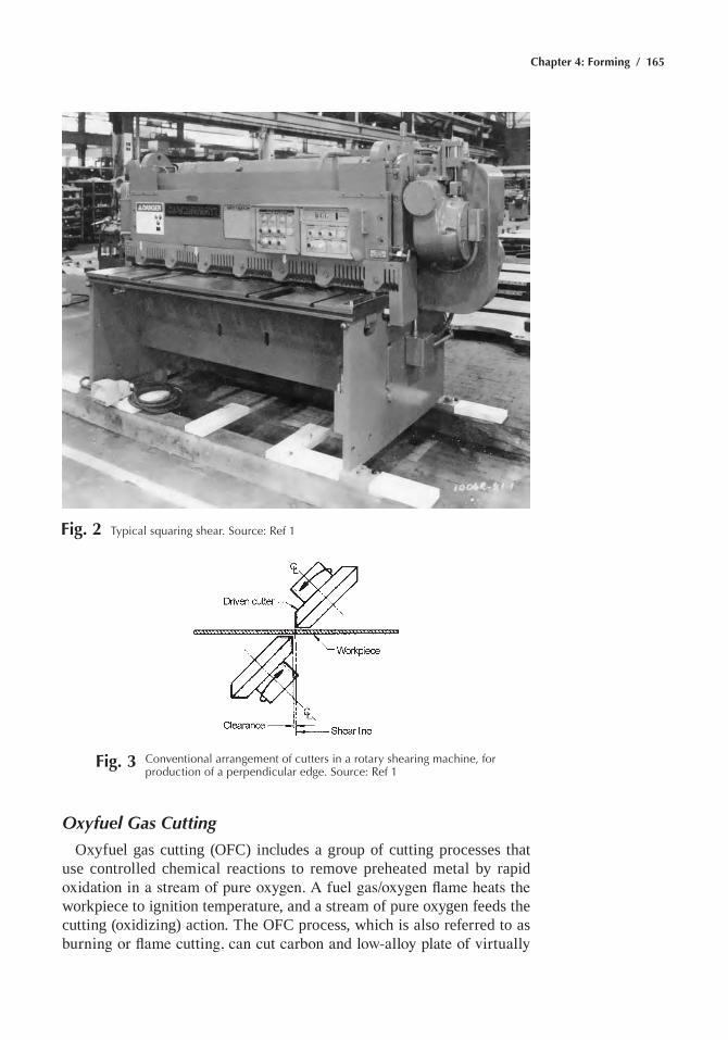
Chapter 4: Forming / 165
Fig. 3 Conventional arrangement of cutters in a rotary shearing machine, for production of a perpendicular edge. Source: ref 1
Fig. 2 typical squaring shear. Source: ref 1
Oxyfuel Gas Cutting
Oxyfuel gas cutting (OFC) includes a group of cutting processes that use controlled chemical reactions to remove preheated metal by rapid oxidation in a stream of pure oxygen. A fuel gas/oxygen flame heats the workpiece to ignition temperature, and a stream of pure oxygen feeds the cutting (oxidizing) action. the OFC process, which is also referred to as burning or flame cutting, can cut carbon and low-alloy plate of virtually
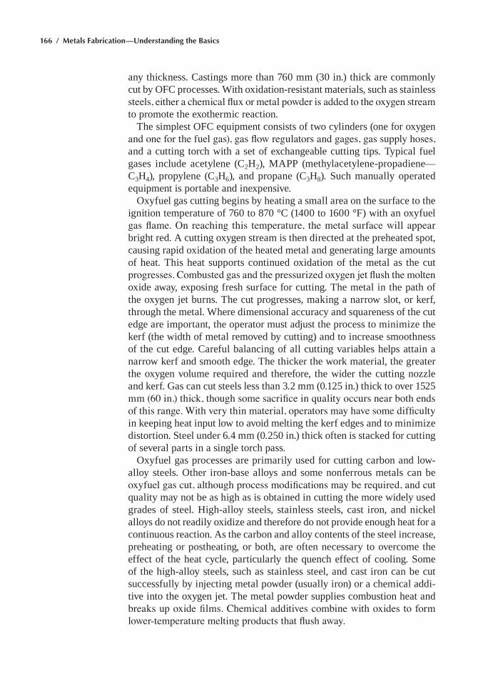
166 / Metals Fabrication—Understanding the Basics
any thickness. Castings more than 760 mm (30 in.) thick are commonly cut by OFC processes. With oxidation-resistant materials, such as stainless steels, either a chemical flux or metal powder is added to the oxygen stream to promote the exothermic reaction.
the simplest OFC equipment consists of two cylinders (one for oxygen and one for the fuel gas), gas flow regulators and gages, gas supply hoses, and a cutting torch with a set of exchangeable cutting tips. typical fuel gases include acetylene (C2h2), maPP (methylacetylene-propadiene—C3h4), propylene (C3h6), and propane (C3h8). Such manually operated equipment is portable and inexpensive.
Oxyfuel gas cutting begins by heating a small area on the surface to the ignition temperature of 760 to 870 °C (1400 to 1600 °F) with an oxyfuel gas flame. On reaching this temperature, the metal surface will appear bright red. a cutting oxygen stream is then directed at the preheated spot, causing rapid oxidation of the heated metal and generating large amounts of heat. this heat supports continued oxidation of the metal as the cut progresses. Combusted gas and the pressurized oxygen jet flush the molten oxide away, exposing fresh surface for cutting. the metal in the path of the oxygen jet burns. the cut progresses, making a narrow slot, or kerf, through the metal. Where dimensional accuracy and squareness of the cut edge are important, the operator must adjust the process to minimize the kerf (the width of metal removed by cutting) and to increase smoothness of the cut edge. Careful balancing of all cutting variables helps attain a narrow kerf and smooth edge. the thicker the work material, the greater the oxygen volume required and therefore, the wider the cutting nozzle and kerf. Gas can cut steels less than 3.2 mm (0.125 in.) thick to over 1525 mm (60 in.) thick, though some sacrifice in quality occurs near both ends of this range. With very thin material, operators may have some difficulty in keeping heat input low to avoid melting the kerf edges and to minimize distortion. Steel under 6.4 mm (0.250 in.) thick often is stacked for cutting of several parts in a single torch pass.
Oxyfuel gas processes are primarily used for cutting carbon and low-alloy steels. Other iron-base alloys and some nonferrous metals can be oxyfuel gas cut, although process modifications may be required, and cut quality may not be as high as is obtained in cutting the more widely used grades of steel. high-alloy steels, stainless steels, cast iron, and nickel alloys do not readily oxidize and therefore do not provide enough heat for a continuous reaction. as the carbon and alloy contents of the steel increase, preheating or postheating, or both, are often necessary to overcome the effect of the heat cycle, particularly the quench effect of cooling. Some of the high-alloy steels, such as stainless steel, and cast iron can be cut successfully by injecting metal powder (usually iron) or a chemical addi-tive into the oxygen jet. the metal powder supplies combustion heat and breaks up oxide films. Chemical additives combine with oxides to form lower-temperature melting products that flush away.
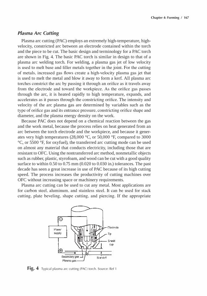
Chapter 4: Forming / 167
Plasma Arc Cutting
Plasma arc cutting (PaC) employs an extremely high-temperature, high-velocity, constricted arc between an electrode contained within the torch and the piece to be cut. the basic design and terminology for a PaC torch are shown in Fig. 4. the basic PaC torch is similar in design to that of a plasma arc welding torch. For welding, a plasma gas jet of low velocity is used to melt base and filler metals together in the joint. For the cutting of metals, increased gas flows create a high-velocity plasma gas jet that is used to melt the metal and blow it away to form a kerf. all plasma arc torches constrict the arc by passing it through an orifice as it travels away from the electrode and toward the workpiece. As the orifice gas passes through the arc, it is heated rapidly to high temperature, expands, and accelerates as it passes through the constricting orifice. The intensity and velocity of the arc plasma gas are determined by variables such as the type of orifice gas and its entrance pressure, constricting orifice shape and diameter, and the plasma energy density on the work.
Because PaC does not depend on a chemical reaction between the gas and the work metal, because the process relies on heat generated from an arc between the torch electrode and the workpiece, and because it gener-ates very high temperatures (28,000 °C, or 50,000 °F, compared to 3000 °C, or 5500 °F, for oxyfuel), the transferred arc cutting mode can be used on almost any material that conducts electricity, including those that are resistant to OFC. Using the nontransferred arc method, nonmetallic objects such as rubber, plastic, styrofoam, and wood can be cut with a good quality surface to within 0.50 to 0.75 mm (0.020 to 0.030 in.) tolerances. the past decade has seen a great increase in use of PaC because of its high cutting speed. the process increases the productivity of cutting machines over OFC without increasing space or machinery requirements.
Plasma arc cutting can be used to cut any metal. most applications are for carbon steel, aluminum, and stainless steel. It can be used for stack cutting, plate beveling, shape cutting, and piercing. If the appropriate
Fig. 4 typical plasma arc cutting (paC) torch. Source: ref 1
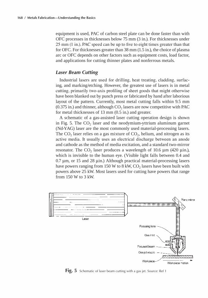
168 / Metals Fabrication—Understanding the Basics
equipment is used, PaC of carbon steel plate can be done faster than with OFC processes in thicknesses below 75 mm (3 in.). For thicknesses under 25 mm (1 in.), PAC speed can be up to five to eight times greater than that for OFC. For thicknesses greater than 38 mm (1.5 in.), the choice of plasma arc or OFC depends on other factors such as equipment costs, load factor, and applications for cutting thinner plates and nonferrous metals.
Laser Beam Cutting
Industrial lasers are used for drilling, heat treating, cladding, surfac-ing, and marking/etching. however, the greatest use of lasers is in metal cutting, primarily two-axis profiling of sheet goods that might otherwise have been blanked out by punch press or fabricated by hand after laborious layout of the pattern. Currently, most metal cutting falls within 9.5 mm (0.375 in.) and thinner, although CO2 lasers are now competitive with PaC for metal thicknesses of 13 mm (0.5 in.) and greater.
a schematic of a gas-assisted laser cutting operation design is shown in Fig. 5. the CO2 laser and the neodymium-yttrium aluminum garnet (Nd-YaG) laser are the most commonly used material-processing lasers. the CO2 laser relies on a gas mixture of CO2, helium, and nitrogen as its active media. It usually uses an electrical discharge between an anode and cathode as the method of media excitation, and a standard two-mirror resonator. the CO2 laser produces a wavelength of 10.6 mm (420 min.), which is invisible to the human eye. (Visible light falls between 0.4 and 0.7 mm, or 15 and 28 min.) although practical material-processing lasers have powers ranging from 150 W to 8 kW, CO2 lasers have been built with powers above 25 kW. most lasers used for cutting have powers that range from 150 W to 3 kW.
Fig. 5 Schematic of laser beam cutting with a gas jet. Source: ref 1
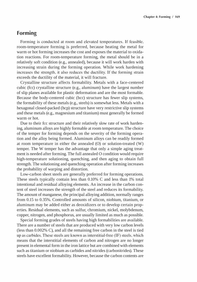
Chapter 4: Forming / 169
Forming
Forming is conducted at room and elevated temperatures. If feasible, room-temperature forming is preferred, because heating the metal for warm or hot forming increases the cost and exposes the material to oxida-tion reactions. For room-temperature forming, the metal should be in a relatively soft condition (e.g., annealed), because it will work harden with increasing strain during the forming operation. While work hardening increases the strength, it also reduces the ductility. If the forming strain exceeds the ductility of the material, it will fracture.
Crystalline structure affects formability. metals with a face-centered cubic (fcc) crystalline structure (e.g., aluminum) have the largest number of slip planes available for plastic deformation and are the most formable. Because the body-centered cubic (bcc) structure has fewer slip systems, the formability of these metals (e.g., steels) is somewhat less. metals with a hexagonal closed-packed (hcp) structure have very restrictive slip systems and these metals (e.g., magnesium and titanium) must generally be formed warm or hot.
Due to their fcc structure and their relatively slow rate of work harden-ing, aluminum alloys are highly formable at room temperature. the choice of the temper for forming depends on the severity of the forming opera-tion and the alloy being formed. aluminum alloys can be readily formed at room temperature in either the annealed (O) or solution-treated (W) temper. the W temper has the advantage that only a simple aging treat-ment is needed after forming. the full annealed O condition would require high-temperature solutioning, quenching, and then aging to obtain full strength. the solutioning and quenching operation after forming increases the probability of warping and distortion.
low-carbon sheet steels are generally preferred for forming operations. these steels typically contain less than 0.10% C and less than 1% total intentional and residual alloying elements. an increase in the carbon con-tent of steel increases the strength of the steel and reduces its formability. the amount of manganese, the principal alloying addition, normally ranges from 0.15 to 0.35%. Controlled amounts of silicon, niobium, titanium, or aluminum may be added either as deoxidizers or to develop certain prop-erties. Residual elements, such as sulfur, chromium, nickel, molybdenum, copper, nitrogen, and phosphorus, are usually limited as much as possible.
Special forming grades of steels having high formabilities are available. there are a number of steels that are produced with very low carbon levels (less than 0.002% C), and all the remaining free carbon in the steel is tied up as carbides. These steels are known as interstitial-free (IF) steels, which means that the interstitial elements of carbon and nitrogen are no longer present in elemental form in the iron lattice but are combined with elements such as titanium or niobium as carbides and nitrides (carbonitrides). these steels have excellent formability. however, because the carbon contents are
170 / Metals Fabrication—Understanding the Basics
extremely low, they are not very strong, with yield strengths of only 138 to 179 mPa (20 to 26 ksi) and tensile strengths of 290 to 338 mPa (42 to 49 ksi). another type of low-carbon steel sheet forming steel is a special class called deep-quality special-killed (DQSK) steel. a preferred orientation is produced by hot rolling the steel on a hot strip mill, followed by rapid cooling. the rapid cooling keeps the aluminum and interstitial elements from forming aluminum nitride (alN) particles (i.e., the aluminum and nitrogen atoms are in solid solution in the iron lattice). after rolling, the steel is annealed to allow aluminum nitride to precipitate. the aluminum nitride plays an important role in the development of the optimal crystal-lographic texture. the DQSK steel is used in deep-drawing applications that are not as demanding as those requiring IF steel.
hexagonal close-packed crystalline metals are usually hot formed. although some hcp alloys can be cold formed, hot forming greatly improves formability, reduces springback, and eliminates the need for stress relief. however, the requirement to hot form increases the cost due to having to heat the material, the need for more expensive tools capable of withstanding the temperature, and the requirement to remove any surface contamination after forming.
Die Materials for Sheet Metal Forming
the useful performance of a forming die is measured in terms of its wear. total wear is affected primarily by the length of the production run and the severity of the forming operation. hence, production quantity and forming severity are the most important factors in selecting die materi-als for forming. The metal being formed, its thickness, and the finish and dimensional tolerances required for the part are also influential factors.
Recommended die materials range from plastics, for low reduction of simple to moderate parts, up to the most wear-resistant surface-hardened tool steels. Parts of even greater severity, or those run in quantities larger than one million, may require dies or inserts of cemented carbide. the varieties of die materials for press forming operations are listed in table 1.
Cast iron is a useful die material for forming parts larger than approx-imately 300 mm (12 in.). Its performance makes it suitable for use in medium production runs or short runs of large parts. When cast iron is used with inserts, it will produce greater quantities. Cast iron should have a structure of predominantly fine pearlite with no massive carbides and a minimum of ferrite.
The zinc alloy recommended for some sheet forming dies has high pattern fidelity when cast but requires very accurate shrink patterns to minimize hand labor finishing. It is economical only for die components at least 300 mm (12 in.) long and is most economical in dies that are approxi-
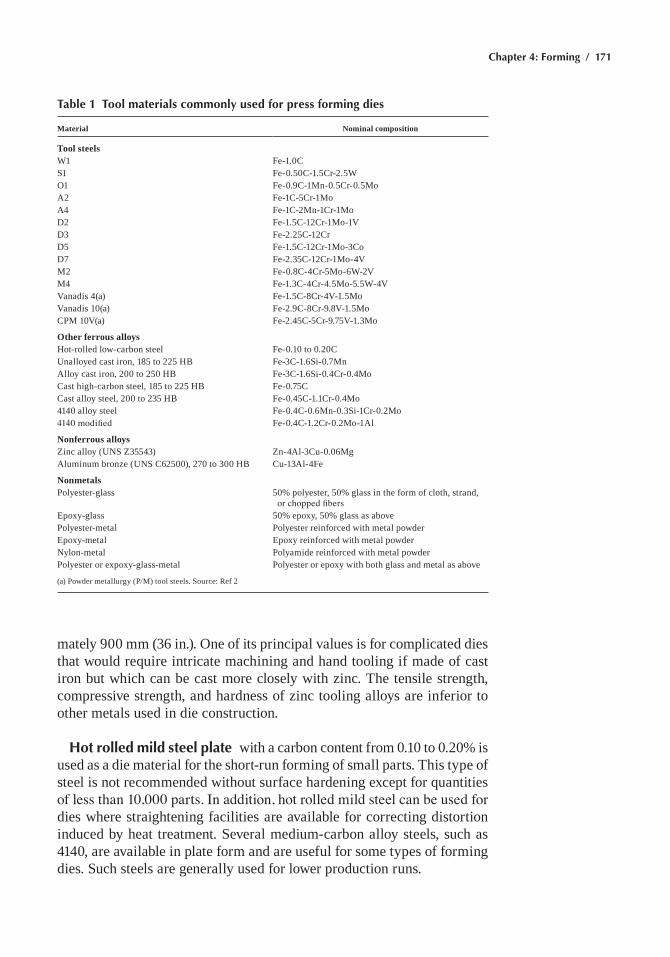
Chapter 4: Forming / 171
Table 1 Tool materials commonly used for press forming dies
Material Nominal composition
Tool steelsW1 Fe-1.0CS1 Fe-0.50C-1.5Cr-2.5WO1 Fe-0.9C-1mn-0.5Cr-0.5moa2 Fe-1C-5Cr-1moa4 Fe-1C-2mn-1Cr-1moD2 Fe-1.5C-12Cr-1mo-1VD3 Fe-2.25C-12CrD5 Fe-1.5C-12Cr-1mo-3CoD7 Fe-2.35C-12Cr-1mo-4Vm2 Fe-0.8C-4Cr-5mo-6W-2Vm4 Fe-1.3C-4Cr-4.5mo-5.5W-4VVanadis 4(a) Fe-1.5C-8Cr-4V-1.5moVanadis 10(a) Fe-2.9C-8Cr-9.8V-1.5moCPm 10V(a) Fe-2.45C-5Cr-9.75V-1.3mo
Other ferrous alloyshot-rolled low-carbon steel Fe-0.10 to 0.20CUnalloyed cast iron, 185 to 225 hB Fe-3C-1.6Si-0.7mnalloy cast iron, 200 to 250 hB Fe-3C-1.6Si-0.4Cr-0.4moCast high-carbon steel, 185 to 225 hB Fe-0.75CCast alloy steel, 200 to 235 hB Fe-0.45C-1.1Cr-0.4mo4140 alloy steel Fe-0.4C-0.6mn-0.3Si-1Cr-0.2mo4140 modified Fe-0.4C-1.2Cr-0.2mo-1al
Nonferrous alloysZinc alloy (UNS Z35543) Zn-4al-3Cu-0.06mgaluminum bronze (UNS C62500), 270 to 300 hB Cu-13al-4Fe
NonmetalsPolyester-glass 50% polyester, 50% glass in the form of cloth, strand,
or chopped fibersepoxy-glass 50% epoxy, 50% glass as abovePolyester-metal Polyester reinforced with metal powderepoxy-metal epoxy reinforced with metal powderNylon-metal Polyamide reinforced with metal powderPolyester or expoxy-glass-metal Polyester or epoxy with both glass and metal as above
(a) Powder metallurgy (P/m) tool steels. Source: Ref 2
mately 900 mm (36 in.). One of its principal values is for complicated dies that would require intricate machining and hand tooling if made of cast iron but which can be cast more closely with zinc. the tensile strength, compressive strength, and hardness of zinc tooling alloys are inferior to other metals used in die construction.
Hot rolled mild steel plate with a carbon content from 0.10 to 0.20% is used as a die material for the short-run forming of small parts. this type of steel is not recommended without surface hardening except for quantities of less than 10,000 parts. In addition, hot rolled mild steel can be used for dies where straightening facilities are available for correcting distortion induced by heat treatment. Several medium-carbon alloy steels, such as 4140, are available in plate form and are useful for some types of forming dies. Such steels are generally used for lower production runs.
172 / Metals Fabrication—Understanding the Basics
Cast steel is used for forming parts larger than 300 mm (12 in.) long where the shape of the part makes a casting more feasible than wrought stock. Plain carbon steel (0.65 to 0.85% C) and alloy cast steel (Fe-0.45C-1.1Cr-0.4mo) are two common compositions. Cast steel is more costly and more difficult to machine than cast iron and is more likely to gall; however, it is tougher than cast iron. One important advantage of cast steel, par-ticularly the plain carbon grade, is its weldability. It can be rewelded with steel or hardfaced with tool steel, aluminum bronze, or other wear-resistant hardfacing alloys. Because of its resistance to galling, it is less desirable for forming carbon and stainless steels than for aluminum and copper alloys. Cast steel is also useful for restrike, flanging, and other types of dies that are less likely to gall or pick up metal from the sheet.
Tool steels, often nitrided, are used for long production runs (100,000 to one million parts) and for tooling applications requiring long wear life and good toughness. as shown in table 1, a wide variety of wrought and powder metallurgy grades are used.
Aluminum bronzes are available in a wide range of hardness from 120 to 340 hRB. these alloys have excellent resistance to galling and are desirable for dies where best finish is required on carbon or stainless steel parts.
Cemented Carbides. For long production runs, inserts of sintered tungsten carbide (WC-10Co) are widely used, especially for deep-draw-ing dies. In dies of approximately 200 mm (8 in.) or less for continuous production of over one million pieces, cemented carbides have proven to be the most economical die material. Such dies have maintained size in drawing 60% reductions of more than 500,000 pieces and have made as many as one million parts with reductions greater than 40% when the steel to be drawn is surface treated with zinc phosphate and soap. however, cemented carbides are not superior to tool steels (such as D2) in complex deep-drawing operations, such as those with reductions greater than 40% that combine drawing with coining or stretching.
Plastics. Plastic dies of longest life are constructed so that the wearing surface is faced with glass cloth that has had most of the plastic material forced out under pressure before and during curing. Polyester, epoxy, phe-nolic resin, and nylon have been used. Plastics are most economical when a model is available as a pattern for the lay-up of the plastic-impregnated glass cloth facing, which is backed up with chopped glass fibers impreg-nated with 50% resin. the strength (70 to 275 mPa, or 10 to 40 ksi), and, in particular, the hardness of plastics are inferior to those of metallic die materials. However, in many cases the regions of high pressure are confined to local areas, which, if anticipated, are strengthened with metal inserts.
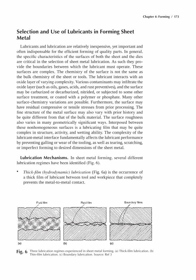
Chapter 4: Forming / 173
Selection and Use of Lubricants in Forming Sheet Metal
lubricants and lubrication are relatively inexpensive, yet important and often indispensable for the efficient forming of quality parts. In general, the specific characteristics of the surfaces of both the sheet and the dies are critical in the selection of sheet metal lubrication. as such they pro-vide the boundaries between which the lubricant must operate. these surfaces are complex. the chemistry of the surface is not the same as the bulk chemistry of the sheet or tools. the lubricant interacts with an oxide layer of varying complexity. Various contaminants may infiltrate the oxide layer (such as oils, gases, acids, and rust preventives), and the surface may be carburized or decarburized, nitrided, or subjected to some other surface treatment, or coated with a polymer or phosphate. many other surface-chemistry variations are possible. Furthermore, the surface may have residual compressive or tensile stresses from prior processing. the fine structure of the metal surface may also vary with prior history and be quite different from that of the bulk material. the surface roughness also varies in many geometrically significant ways. Interposed between these nonhomogeneous surfaces is a lubricating film that may be quite complex in structure, activity, and wetting ability. the complexity of the lubricant-metal interface fundamentally affects the lubricant performance by preventing galling or wear of the tooling, as well as tearing, scratching, or imperfect forming to desired dimensions of the sheet metal.
Lubrication Mechanisms. In sheet metal forming, several different lubrication regimes have been identified (Fig. 6).
• Thick-film (hydrodynamic) lubrication (Fig. 6a) is the occurrence of a thick film of lubricant between tool and workpiece that completely prevents the metal-to-metal contact.
Fig. 6 three lubrication regimes experienced in sheet metal forming. (a) thick-film lubrication. (b) thin-film lubrication. (c) Boundary lubrication. Source: ref 3
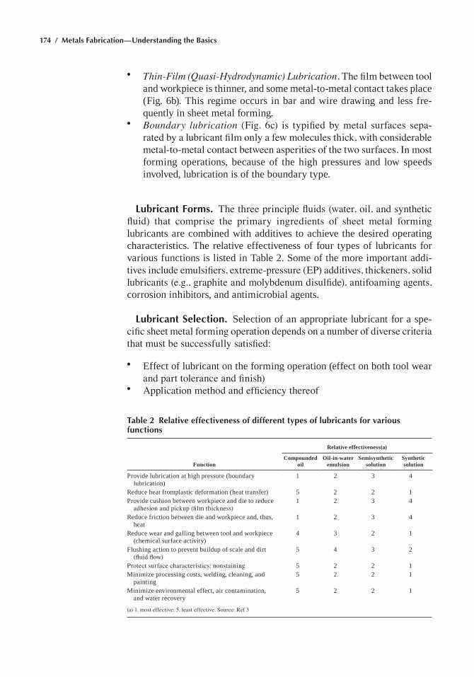
174 / Metals Fabrication—Understanding the Basics
• Thin-Film (Quasi-Hydrodynamic) Lubrication. The film between tool and workpiece is thinner, and some metal-to-metal contact takes place (Fig. 6b). this regime occurs in bar and wire drawing and less fre-quently in sheet metal forming.
• Boundary lubrication (Fig. 6c) is typified by metal surfaces sepa-rated by a lubricant film only a few molecules thick, with considerable metal-to-metal contact between asperities of the two surfaces. In most forming operations, because of the high pressures and low speeds involved, lubrication is of the boundary type.
Lubricant Forms. The three principle fluids (water, oil, and synthetic fluid) that comprise the primary ingredients of sheet metal forming lubricants are combined with additives to achieve the desired operating characteristics. the relative effectiveness of four types of lubricants for various functions is listed in table 2. Some of the more important addi-tives include emulsifiers, extreme-pressure (EP) additives, thickeners, solid lubricants (e.g., graphite and molybdenum disulfide), antifoaming agents, corrosion inhibitors, and antimicrobial agents.
Lubricant Selection. Selection of an appropriate lubricant for a spe-cific sheet metal forming operation depends on a number of diverse criteria that must be successfully satisfied:
• effect of lubricant on the forming operation (effect on both tool wear and part tolerance and finish)
• Application method and efficiency thereof
Table 2 Relative effectiveness of different types of lubricants for various functions
Relative effectiveness(a)
FunctionCompounded
oilOil-in-water
emulsionSemisynthetic
solutionSynthetic solution
Provide lubrication at high pressure (boundary lubrication)
1 2 3 4
Reduce heat fromplastic deformation (heat transfer) 5 2 2 1Provide cushion between workpiece and die to reduce
adhesion and pickup (film thickness)1 2 3 4
Reduce friction between die and workpiece and, thus, heat
1 2 3 4
Reduce wear and galling between tool and workpiece (chemical surface activity)
4 3 2 1
Flushing action to prevent buildup of scale and dirt (fluid flow)
5 4 3 2
Protect surface characteristics; nonstaining 5 2 2 1minimize processing costs, welding, cleaning, and
painting5 2 2 1
minimize environmental effect, air contamination, and water recovery
5 2 2 1
(a) 1, most effective; 5, least effective. Source: Ref 3
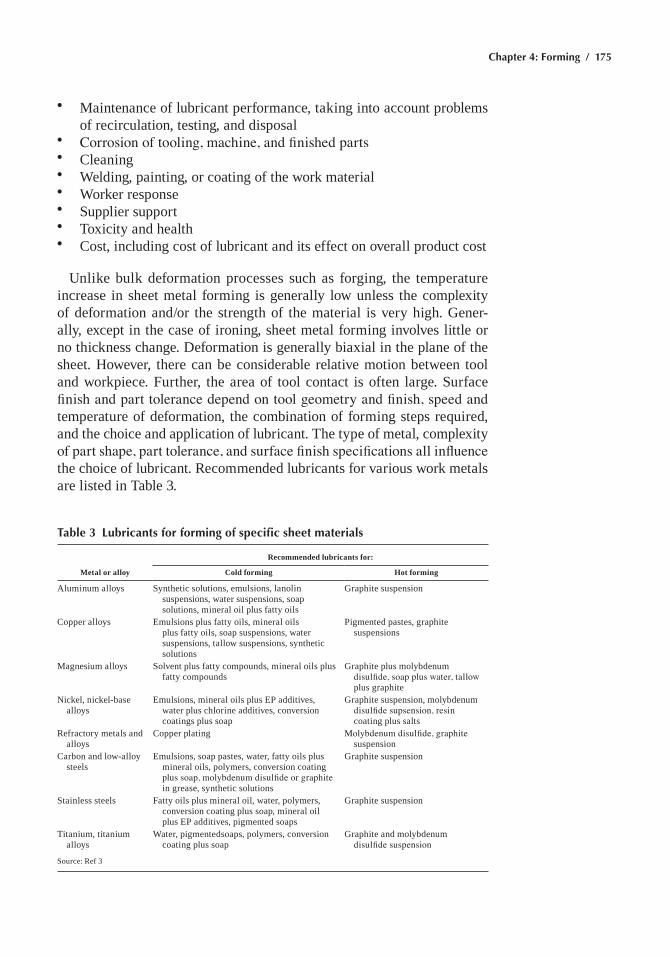
Chapter 4: Forming / 175
• maintenance of lubricant performance, taking into account problems of recirculation, testing, and disposal
• Corrosion of tooling, machine, and finished parts• Cleaning• Welding, painting, or coating of the work material• Worker response• Supplier support• toxicity and health• Cost, including cost of lubricant and its effect on overall product cost
Unlike bulk deformation processes such as forging, the temperature increase in sheet metal forming is generally low unless the complexity of deformation and/or the strength of the material is very high. Gener-ally, except in the case of ironing, sheet metal forming involves little or no thickness change. Deformation is generally biaxial in the plane of the sheet. however, there can be considerable relative motion between tool and workpiece. Further, the area of tool contact is often large. Surface finish and part tolerance depend on tool geometry and finish, speed and temperature of deformation, the combination of forming steps required, and the choice and application of lubricant. the type of metal, complexity of part shape, part tolerance, and surface finish specifications all influence the choice of lubricant. Recommended lubricants for various work metals are listed in table 3.
Table 3 Lubricants for forming of specific sheet materials
Recommended lubricants for:
Metal or alloy Cold forming Hot forming
aluminum alloys Synthetic solutions, emulsions, lanolin suspensions, water suspensions, soap solutions, mineral oil plus fatty oils
Graphite suspension
Copper alloys emulsions plus fatty oils, mineral oils plus fatty oils, soap suspensions, water suspensions, tallow suspensions, synthetic solutions
Pigmented pastes, graphite suspensions
magnesium alloys Solvent plus fatty compounds, mineral oils plus fatty compounds
Graphite plus molybdenum disulfide, soap plus water, tallow plus graphite
Nickel, nickel-base alloys
emulsions, mineral oils plus eP additives, water plus chlorine additives, conversion coatings plus soap
Graphite suspension, molybdenum disulfide supsension, resin coating plus salts
Refractory metals and alloys
Copper plating Molybdenum disulfide, graphite suspension
Carbon and low-alloy steels
emulsions, soap pastes, water, fatty oils plus mineral oils, polymers, conversion coating plus soap, molybdenum disulfide or graphite in grease, synthetic solutions
Graphite suspension
Stainless steels Fatty oils plus mineral oil, water, polymers, conversion coating plus soap, mineral oil plus eP additives, pigmented soaps
Graphite suspension
titanium, titanium alloys
Water, pigmentedsoaps, polymers, conversion coating plus soap
Graphite and molybdenum disulfide suspension
Source: Ref 3
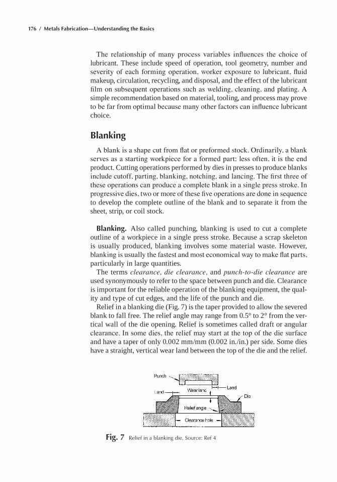
176 / Metals Fabrication—Understanding the Basics
The relationship of many process variables influences the choice of lubricant. these include speed of operation, tool geometry, number and severity of each forming operation, worker exposure to lubricant, fluid makeup, circulation, recycling, and disposal, and the effect of the lubricant film on subsequent operations such as welding, cleaning, and plating. A simple recommendation based on material, tooling, and process may prove to be far from optimal because many other factors can influence lubricant choice.
Blanking
A blank is a shape cut from flat or preformed stock. Ordinarily, a blank serves as a starting workpiece for a formed part; less often, it is the end product. Cutting operations performed by dies in presses to produce blanks include cutoff, parting, blanking, notching, and lancing. The first three of these operations can produce a complete blank in a single press stroke. In progressive dies, two or more of these five operations are done in sequence to develop the complete outline of the blank and to separate it from the sheet, strip, or coil stock.
Blanking. also called punching, blanking is used to cut a complete outline of a workpiece in a single press stroke. Because a scrap skeleton is usually produced, blanking involves some material waste. however, blanking is usually the fastest and most economical way to make flat parts, particularly in large quantities.
the terms clearance, die clearance, and punch-to-die clearance are used synonymously to refer to the space between punch and die. Clearance is important for the reliable operation of the blanking equipment, the qual-ity and type of cut edges, and the life of the punch and die.
Relief in a blanking die (Fig. 7) is the taper provided to allow the severed blank to fall free. the relief angle may range from 0.5° to 2° from the ver-tical wall of the die opening. Relief is sometimes called draft or angular clearance. In some dies, the relief may start at the top of the die surface and have a taper of only 0.002 mm/mm (0.002 in./in.) per side. Some dies have a straight, vertical wear land between the top of the die and the relief.
Fig. 7 relief in a blanking die. Source: ref 4
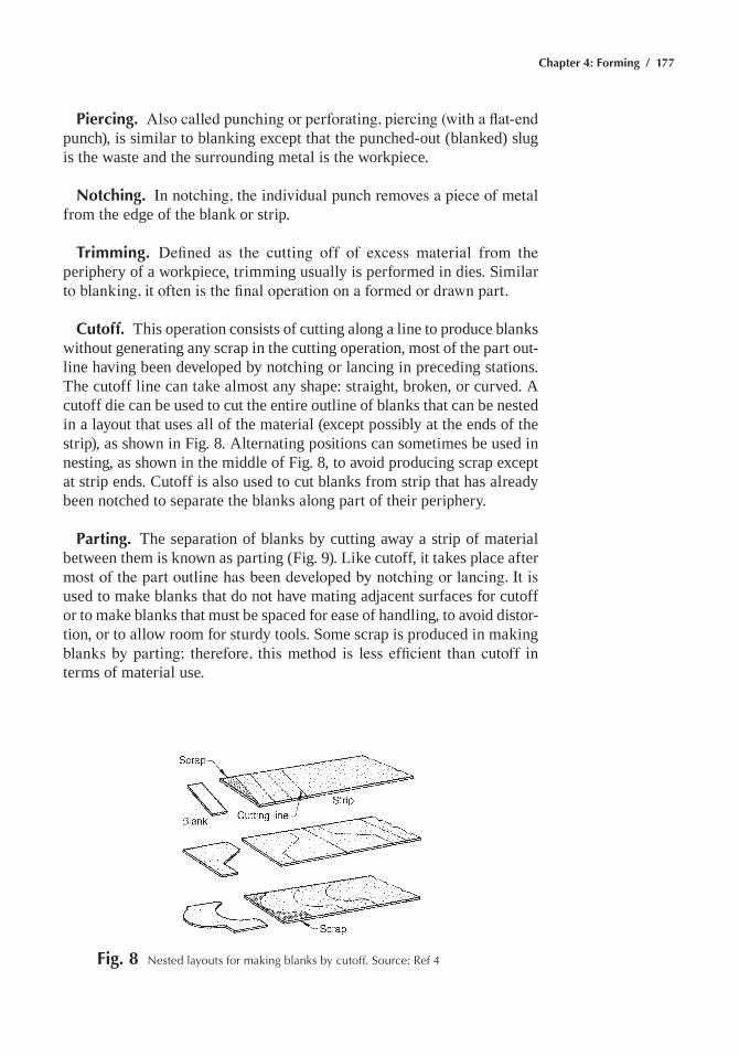
Chapter 4: Forming / 177
Piercing. Also called punching or perforating, piercing (with a flat-end punch), is similar to blanking except that the punched-out (blanked) slug is the waste and the surrounding metal is the workpiece.
Notching. In notching, the individual punch removes a piece of metal from the edge of the blank or strip.
Trimming. Defined as the cutting off of excess material from the periphery of a workpiece, trimming usually is performed in dies. Similar to blanking, it often is the final operation on a formed or drawn part.
Cutoff. this operation consists of cutting along a line to produce blanks without generating any scrap in the cutting operation, most of the part out-line having been developed by notching or lancing in preceding stations. the cutoff line can take almost any shape: straight, broken, or curved. a cutoff die can be used to cut the entire outline of blanks that can be nested in a layout that uses all of the material (except possibly at the ends of the strip), as shown in Fig. 8. alternating positions can sometimes be used in nesting, as shown in the middle of Fig. 8, to avoid producing scrap except at strip ends. Cutoff is also used to cut blanks from strip that has already been notched to separate the blanks along part of their periphery.
Parting. the separation of blanks by cutting away a strip of material between them is known as parting (Fig. 9). like cutoff, it takes place after most of the part outline has been developed by notching or lancing. It is used to make blanks that do not have mating adjacent surfaces for cutoff or to make blanks that must be spaced for ease of handling, to avoid distor-tion, or to allow room for sturdy tools. Some scrap is produced in making blanks by parting; therefore, this method is less efficient than cutoff in terms of material use.
Fig. 8 Nested layouts for making blanks by cutoff. Source: ref 4
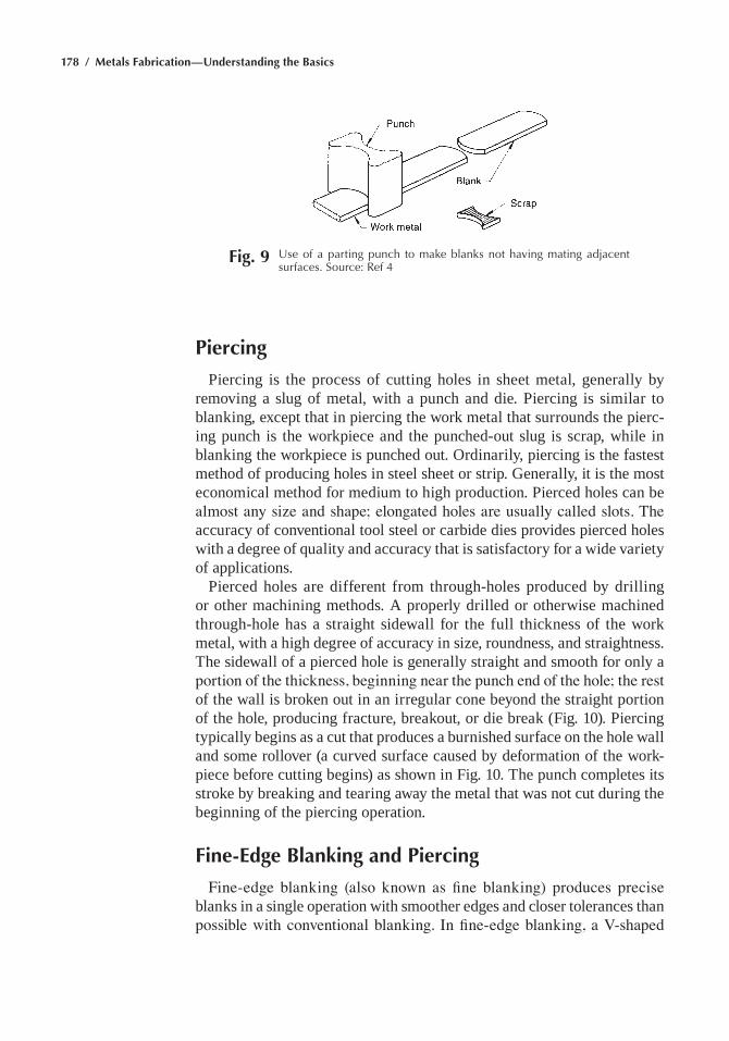
178 / Metals Fabrication—Understanding the Basics
Piercing
Piercing is the process of cutting holes in sheet metal, generally by removing a slug of metal, with a punch and die. Piercing is similar to blanking, except that in piercing the work metal that surrounds the pierc-ing punch is the workpiece and the punched-out slug is scrap, while in blanking the workpiece is punched out. Ordinarily, piercing is the fastest method of producing holes in steel sheet or strip. Generally, it is the most economical method for medium to high production. Pierced holes can be almost any size and shape; elongated holes are usually called slots. The accuracy of conventional tool steel or carbide dies provides pierced holes with a degree of quality and accuracy that is satisfactory for a wide variety of applications.
Pierced holes are different from through-holes produced by drilling or other machining methods. a properly drilled or otherwise machined through-hole has a straight sidewall for the full thickness of the work metal, with a high degree of accuracy in size, roundness, and straightness. the sidewall of a pierced hole is generally straight and smooth for only a portion of the thickness, beginning near the punch end of the hole; the rest of the wall is broken out in an irregular cone beyond the straight portion of the hole, producing fracture, breakout, or die break (Fig. 10). Piercing typically begins as a cut that produces a burnished surface on the hole wall and some rollover (a curved surface caused by deformation of the work-piece before cutting begins) as shown in Fig. 10. the punch completes its stroke by breaking and tearing away the metal that was not cut during the beginning of the piercing operation.
Fine-Edge Blanking and Piercing
Fine-edge blanking (also known as fine blanking) produces precise blanks in a single operation with smoother edges and closer tolerances than possible with conventional blanking. In fine-edge blanking, a V-shaped
Fig. 9 Use of a parting punch to make blanks not having mating adjacent surfaces. Source: ref 4
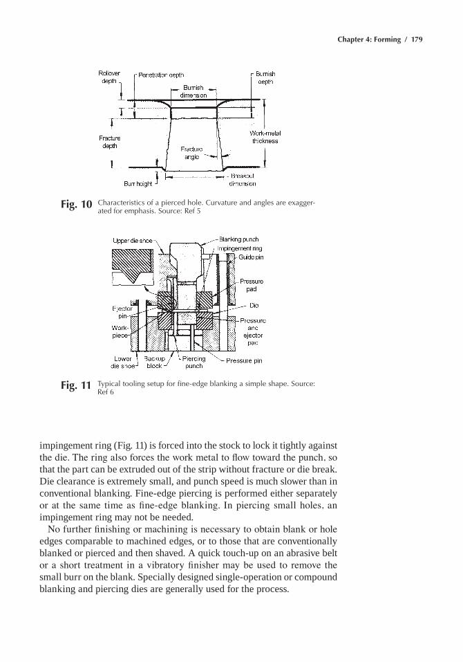
Chapter 4: Forming / 179
impingement ring (Fig. 11) is forced into the stock to lock it tightly against the die. The ring also forces the work metal to flow toward the punch, so that the part can be extruded out of the strip without fracture or die break. Die clearance is extremely small, and punch speed is much slower than in conventional blanking. Fine-edge piercing is performed either separately or at the same time as fine-edge blanking. In piercing small holes, an impingement ring may not be needed.
No further finishing or machining is necessary to obtain blank or hole edges comparable to machined edges, or to those that are conventionally blanked or pierced and then shaved. a quick touch-up on an abrasive belt or a short treatment in a vibratory finisher may be used to remove the small burr on the blank. Specially designed single-operation or compound blanking and piercing dies are generally used for the process.
Fig. 10 Characteristics of a pierced hole. Curvature and angles are exagger-ated for emphasis. Source: ref 5
Fig. 11 typical tooling setup for fine-edge blanking a simple shape. Source: ref 6
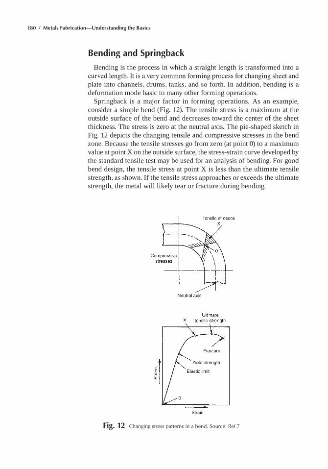
180 / Metals Fabrication—Understanding the Basics
Bending and Springback
Bending is the process in which a straight length is transformed into a curved length. It is a very common forming process for changing sheet and plate into channels, drums, tanks, and so forth. In addition, bending is a deformation mode basic to many other forming operations.
Springback is a major factor in forming operations. as an example, consider a simple bend (Fig. 12). the tensile stress is a maximum at the outside surface of the bend and decreases toward the center of the sheet thickness. the stress is zero at the neutral axis. the pie-shaped sketch in Fig. 12 depicts the changing tensile and compressive stresses in the bend zone. Because the tensile stresses go from zero (at point 0) to a maximum value at point X on the outside surface, the stress-strain curve developed by the standard tensile test may be used for an analysis of bending. For good bend design, the tensile stress at point X is less than the ultimate tensile strength, as shown. If the tensile stress approaches or exceeds the ultimate strength, the metal will likely tear or fracture during bending.
Fig. 12 Changing stress patterns in a bend. Source: ref 7
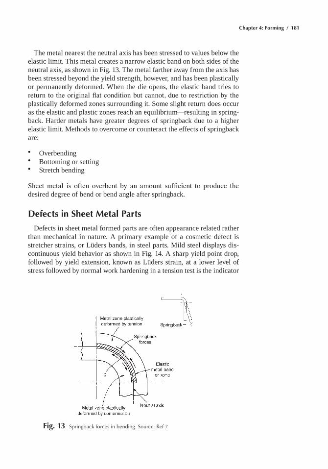
Chapter 4: Forming / 181
the metal nearest the neutral axis has been stressed to values below the elastic limit. this metal creates a narrow elastic band on both sides of the neutral axis, as shown in Fig. 13. the metal farther away from the axis has been stressed beyond the yield strength, however, and has been plastically or permanently deformed. When the die opens, the elastic band tries to return to the original flat condition but cannot, due to restriction by the plastically deformed zones surrounding it. Some slight return does occur as the elastic and plastic zones reach an equilibrium—resulting in spring-back. harder metals have greater degrees of springback due to a higher elastic limit. methods to overcome or counteract the effects of springback are:
• Overbending• Bottoming or setting• Stretch bending
Sheet metal is often overbent by an amount sufficient to produce the desired degree of bend or bend angle after springback.
Defects in Sheet Metal Parts
Defects in sheet metal formed parts are often appearance related rather than mechanical in nature. a primary example of a cosmetic defect is stretcher strains, or lüders bands, in steel parts. mild steel displays dis-continuous yield behavior as shown in Fig. 14. a sharp yield point drop, followed by yield extension, known as lüders strain, at a lower level of stress followed by normal work hardening in a tension test is the indicator
Fig. 13 Springback forces in bending. Source: ref 7
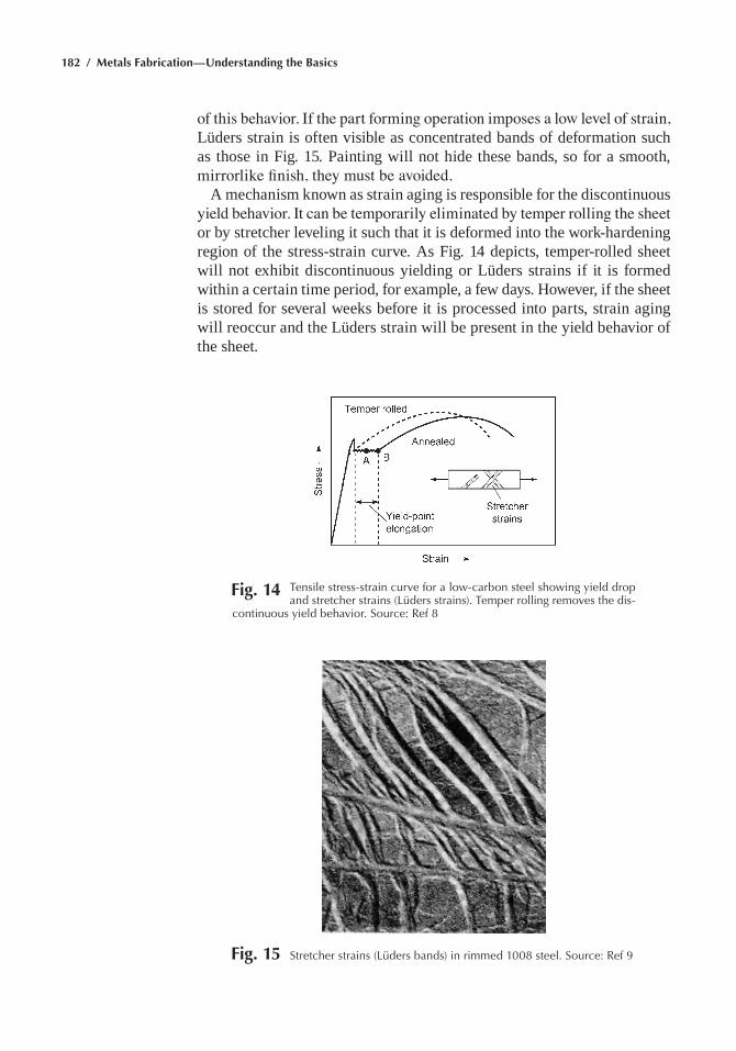
182 / Metals Fabrication—Understanding the Basics
of this behavior. If the part forming operation imposes a low level of strain, lüders strain is often visible as concentrated bands of deformation such as those in Fig. 15. Painting will not hide these bands, so for a smooth, mirrorlike finish, they must be avoided.
a mechanism known as strain aging is responsible for the discontinuous yield behavior. It can be temporarily eliminated by temper rolling the sheet or by stretcher leveling it such that it is deformed into the work-hardening region of the stress-strain curve. as Fig. 14 depicts, temper-rolled sheet will not exhibit discontinuous yielding or lüders strains if it is formed within a certain time period, for example, a few days. however, if the sheet is stored for several weeks before it is processed into parts, strain aging will reoccur and the lüders strain will be present in the yield behavior of the sheet.
Fig. 14 tensile stress-strain curve for a low-carbon steel showing yield drop and stretcher strains (Lüders strains). temper rolling removes the dis-
continuous yield behavior. Source: ref 8
Fig. 15 Stretcher strains (Lüders bands) in rimmed 1008 steel. Source: ref 9
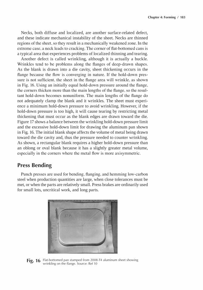
Chapter 4: Forming / 183
Necks, both diffuse and localized, are another surface-related defect, and these indicate mechanical instability of the sheet. Necks are thinned regions of the sheet, so they result in a mechanically weakened zone. In the extreme case, a neck leads to cracking. The corner of flat-bottomed cans is a typical area that experiences problems of localized thinning and tearing.
another defect is called wrinkling, although it is actually a buckle. Wrinkles tend to be problems along the flanges of deep-drawn shapes. as the blank is drawn into a die cavity, sheet thickening occurs in the flange because the flow is converging in nature. If the hold-down pres-sure is not sufficient, the sheet in the flange area will wrinkle, as shown in Fig. 16. Using an initially equal hold-down pressure around the flange, the corners thicken more than the main lengths of the flange, so the resul-tant hold-down becomes nonuniform. The main lengths of the flange do not adequately clamp the blank and it wrinkles. the sheet must experi-ence a minimum hold-down pressure to avoid wrinkling. however, if the hold-down pressure is too high, it will cause tearing by restricting metal thickening that must occur as the blank edges are drawn toward the die. Figure 17 shows a balance between the wrinkling hold-down pressure limit and the excessive hold-down limit for drawing the aluminum pan shown in Fig. 16. the initial blank shape affects the volume of metal being drawn toward the die cavity and, thus the pressure needed to counter wrinkling. as shown, a rectangular blank requires a higher hold-down pressure than an oblong or oval blank because it has a slightly greater metal volume, especially in the corners where the metal flow is more axisymmetric.
Press Bending
Punch presses are used for bending, flanging, and hemming low-carbon steel when production quantities are large, when close tolerances must be met, or when the parts are relatively small. Press brakes are ordinarily used for small lots, uncritical work, and long parts.
Fig. 16 Flat-bottomed pan stamped from 2008-t4 aluminum sheet showing wrinkling on the flange. Source: ref 10
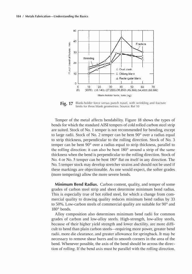
184 / Metals Fabrication—Understanding the Basics
temper of the metal affects bendability. Figure 18 shows the types of bends for which the standard AISI tempers of cold rolled carbon steel strip are suited. Stock of No. 1 temper is not recommended for bending, except to large radii. Stock of No. 2 temper can be bent 90° over a radius equal to strip thickness, perpendicular to the rolling direction. Stock of No. 3 temper can be bent 90° over a radius equal to strip thickness, parallel to the rolling direction; it can also be bent 180° around a strip of the same thickness when the bend is perpendicular to the rolling direction. Stock of No. 4 or No. 5 temper can be bent 180° flat on itself in any direction. The No. 5 temper stock may develop stretcher strains and should not be used if these markings are objectionable. as one would expect, the softer grades (more tempering) allow the more severe bends.
Minimum Bend Radius. Carbon content, quality, and temper of some grades of carbon steel strip and sheet determine minimum bend radius. this is especially true of hot rolled steel, for which a change from com-mercial quality to drawing quality reduces minimum bend radius by 33 to 50%. low-carbon steels of commercial quality are suitable for 90° and 180° bends.
alloy composition also determines minimum bend radii for common grades of carbon and low-alloy steels. high-strength, low-alloy steels, because of their higher yield strength and lower ductility, are more diffi-cult to bend than plain carbon steels—requiring more power, greater bend radii, more die clearance, and greater allowance for springback. It may be necessary to remove shear burrs and to smooth corners in the area of the bend. Whenever possible, the axis of the bend should be across the direc-tion of rolling. If the bend axis must be parallel with the rolling direction,
Fig. 17 Blank-holder force versus punch travel, with wrinkling and fracture limits for three blank geometries. Source: ref 10
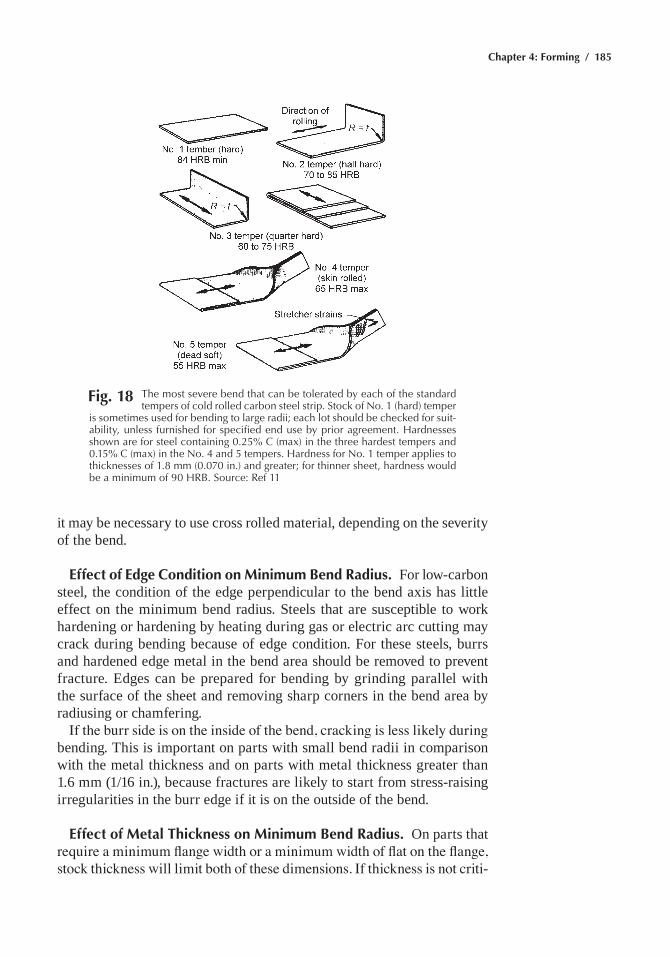
Chapter 4: Forming / 185
it may be necessary to use cross rolled material, depending on the severity of the bend.
Effect of Edge Condition on Minimum Bend Radius. For low-carbon steel, the condition of the edge perpendicular to the bend axis has little effect on the minimum bend radius. Steels that are susceptible to work hardening or hardening by heating during gas or electric arc cutting may crack during bending because of edge condition. For these steels, burrs and hardened edge metal in the bend area should be removed to prevent fracture. edges can be prepared for bending by grinding parallel with the surface of the sheet and removing sharp corners in the bend area by radiusing or chamfering.
If the burr side is on the inside of the bend, cracking is less likely during bending. this is important on parts with small bend radii in comparison with the metal thickness and on parts with metal thickness greater than 1.6 mm (1/16 in.), because fractures are likely to start from stress-raising irregularities in the burr edge if it is on the outside of the bend.
Effect of Metal Thickness on Minimum Bend Radius. On parts that require a minimum flange width or a minimum width of flat on the flange, stock thickness will limit both of these dimensions. If thickness is not criti-
Fig. 18 the most severe bend that can be tolerated by each of the standard tempers of cold rolled carbon steel strip. Stock of No. 1 (hard) temper
is sometimes used for bending to large radii; each lot should be checked for suit-ability, unless furnished for specified end use by prior agreement. hardnesses shown are for steel containing 0.25% C (max) in the three hardest tempers and 0.15% C (max) in the No. 4 and 5 tempers. hardness for No. 1 temper applies to thicknesses of 1.8 mm (0.070 in.) and greater; for thinner sheet, hardness would be a minimum of 90 hrB. Source: ref 11
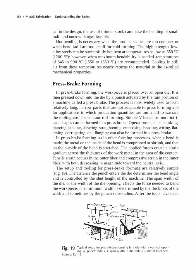
186 / Metals Fabrication—Understanding the Basics
cal in the design, the use of thinner stock can make the bending of small radii and narrow flanges feasible.
hot bending is necessary when the product shapes are too complex or when bend radii are too small for cold forming. the high-strength, low-alloy steels can be successfully hot bent at temperatures as low as 650 °C (1200 °F); however, when maximum bendability is needed, temperatures of 845 to 900 °C (1550 to 1650 °F) are recommended. Cooling in still air from these temperatures nearly returns the material to the as-rolled mechanical properties.
Press-Brake Forming
In press-brake forming, the workpiece is placed over an open die. It is then pressed down into the die by a punch actuated by the ram portion of a machine called a press brake. the process is most widely used to form relatively long, narrow parts that are not adaptable to press forming and for applications in which production quantities are too small to warrant the tooling cost for contour roll forming. Simple V-bends or more intri-cate shapes can be formed in a press brake. Operations such as blanking, piercing, lancing, shearing, straightening, embossing, beading, wiring, flat-tening, corrugating, and flanging can also be formed in a press brake.
In press-brake forming, as in other forming processes, when a bend is made, the metal on the inside of the bend is compressed or shrunk, and that on the outside of the bend is stretched. the applied forces create a strain gradient across the thickness of the work metal in the area of die contact. Tensile strain occurs in the outer fiber and compressive strain in the inner fiber, with both decreasing in magnitude toward the neutral axis.
the setup and tooling for press-brake forming are relatively simple (Fig. 19). the distance the punch enters the die determines the bend angle and is controlled by the shut height of the machine. the span width of the die, or the width of the die opening, affects the force needed to bend the workpiece. the minimum width is determined by the thickness of the work and sometimes by the punch-nose radius. after the tools have been
Fig. 19 typical setup for press-brake forming in a die with a vertical open-ing. R, punch radius; s, span width; r, die radius; t, metal thickness.
Source: ref 12
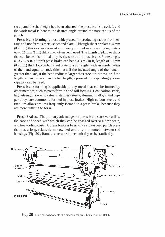
Chapter 4: Forming / 187
set up and the shut height has been adjusted, the press brake is cycled, and the work metal is bent to the desired angle around the nose radius of the punch.
Press-brake forming is most widely used for producing shapes from fer-rous and nonferrous metal sheet and plate. although sheet or plate 6.4 mm (0.25 in.) thick or less is most commonly formed in a press brake, metals up to 25 mm (1 in.) thick have often been used. the length of plate or sheet that can be bent is limited only by the size of the press brake. For example, a 5350 kN (600 tonf) press brake can bend a 3 m (10 ft) length of 19 mm (0.25 in.) thick low-carbon steel plate to a 90° angle, with an inside radius of the bend equal to stock thickness. If the included angle of the bend is greater than 90°, if the bend radius is larger than stock thickness, or if the length of bend is less than the bed length, a press of correspondingly lower capacity can be used.
Press-brake forming is applicable to any metal that can be formed by other methods, such as press forming and roll forming. low-carbon steels, high-strength low-alloy steels, stainless steels, aluminum alloys, and cop-per alloys are commonly formed in press brakes. high-carbon steels and titanium alloys are less frequently formed in a press brake, because they are more difficult to form.
Press Brakes. the primary advantages of press brakes are versatility, the ease and speed with which they can be changed over to a new setup, and low tooling costs. a press brake is basically a slow-speed punch press that has a long, relatively narrow bed and a ram mounted between end housings (Fig. 20). Rams are actuated mechanically or hydraulically.
Fig. 20 principal components of a mechanical press brake. Source: ref 12
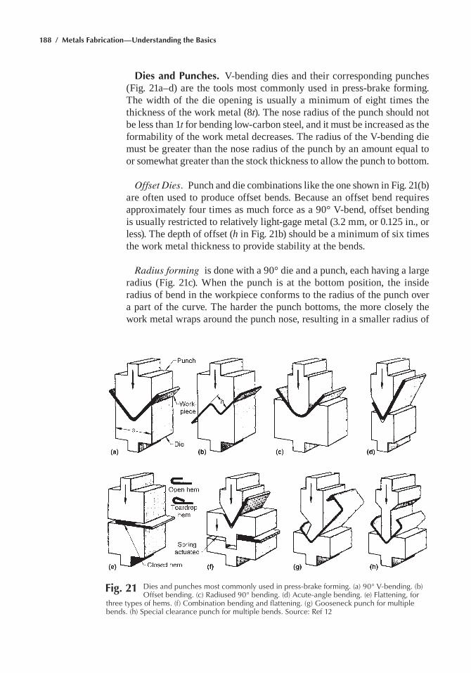
188 / Metals Fabrication—Understanding the Basics
Dies and Punches. V-bending dies and their corresponding punches (Fig. 21a–d) are the tools most commonly used in press-brake forming. the width of the die opening is usually a minimum of eight times the thickness of the work metal (8t). the nose radius of the punch should not be less than 1t for bending low-carbon steel, and it must be increased as the formability of the work metal decreases. the radius of the V-bending die must be greater than the nose radius of the punch by an amount equal to or somewhat greater than the stock thickness to allow the punch to bottom.
Offset Dies. Punch and die combinations like the one shown in Fig. 21(b) are often used to produce offset bends. Because an offset bend requires approximately four times as much force as a 90° V-bend, offset bending is usually restricted to relatively light-gage metal (3.2 mm, or 0.125 in., or less). the depth of offset (h in Fig. 21b) should be a minimum of six times the work metal thickness to provide stability at the bends.
Radius forming is done with a 90° die and a punch, each having a large radius (Fig. 21c). When the punch is at the bottom position, the inside radius of bend in the workpiece conforms to the radius of the punch over a part of the curve. the harder the punch bottoms, the more closely the work metal wraps around the punch nose, resulting in a smaller radius of
Fig. 21 Dies and punches most commonly used in press-brake forming. (a) 90° V-bending. (b) Offset bending. (c) radiused 90° bending. (d) acute-angle bending. (e) Flattening, for
three types of hems. (f) Combination bending and flattening. (g) Gooseneck punch for multiple bends. (h) Special clearance punch for multiple bends. Source: ref 12
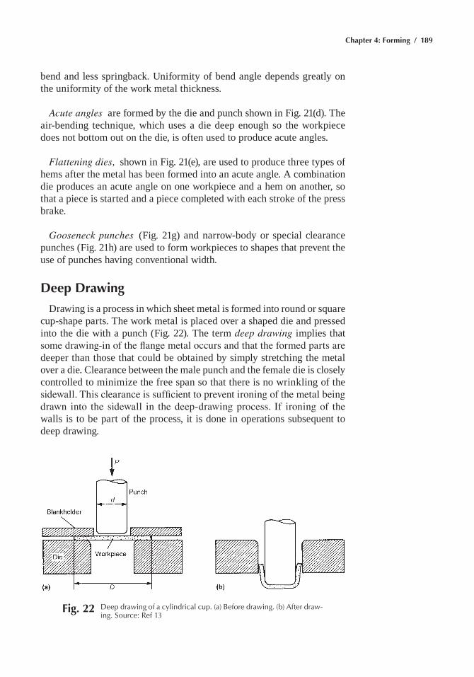
Chapter 4: Forming / 189
bend and less springback. Uniformity of bend angle depends greatly on the uniformity of the work metal thickness.
Acute angles are formed by the die and punch shown in Fig. 21(d). the air-bending technique, which uses a die deep enough so the workpiece does not bottom out on the die, is often used to produce acute angles.
Flattening dies, shown in Fig. 21(e), are used to produce three types of hems after the metal has been formed into an acute angle. a combination die produces an acute angle on one workpiece and a hem on another, so that a piece is started and a piece completed with each stroke of the press brake.
Gooseneck punches (Fig. 21g) and narrow-body or special clearance punches (Fig. 21h) are used to form workpieces to shapes that prevent the use of punches having conventional width.
Deep Drawing
Drawing is a process in which sheet metal is formed into round or square cup-shape parts. the work metal is placed over a shaped die and pressed into the die with a punch (Fig. 22). the term deep drawing implies that some drawing-in of the flange metal occurs and that the formed parts are deeper than those that could be obtained by simply stretching the metal over a die. Clearance between the male punch and the female die is closely controlled to minimize the free span so that there is no wrinkling of the sidewall. This clearance is sufficient to prevent ironing of the metal being drawn into the sidewall in the deep-drawing process. If ironing of the walls is to be part of the process, it is done in operations subsequent to deep drawing.
Fig. 22 Deep drawing of a cylindrical cup. (a) Before drawing. (b) after draw-ing. Source: ref 13
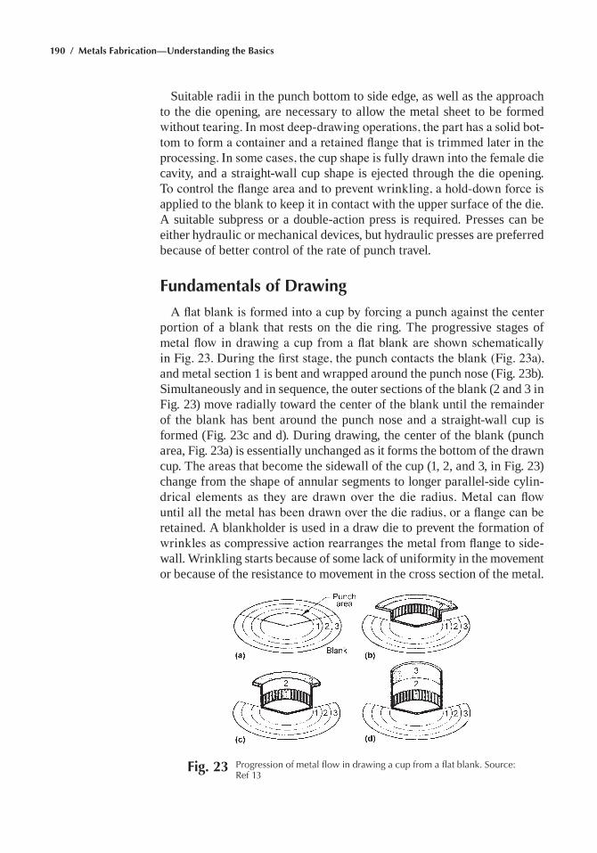
190 / Metals Fabrication—Understanding the Basics
Suitable radii in the punch bottom to side edge, as well as the approach to the die opening, are necessary to allow the metal sheet to be formed without tearing. In most deep-drawing operations, the part has a solid bot-tom to form a container and a retained flange that is trimmed later in the processing. In some cases, the cup shape is fully drawn into the female die cavity, and a straight-wall cup shape is ejected through the die opening. To control the flange area and to prevent wrinkling, a hold-down force is applied to the blank to keep it in contact with the upper surface of the die. a suitable subpress or a double-action press is required. Presses can be either hydraulic or mechanical devices, but hydraulic presses are preferred because of better control of the rate of punch travel.
Fundamentals of Drawing
A flat blank is formed into a cup by forcing a punch against the center portion of a blank that rests on the die ring. the progressive stages of metal flow in drawing a cup from a flat blank are shown schematically in Fig. 23. During the first stage, the punch contacts the blank (Fig. 23a), and metal section 1 is bent and wrapped around the punch nose (Fig. 23b). Simultaneously and in sequence, the outer sections of the blank (2 and 3 in Fig. 23) move radially toward the center of the blank until the remainder of the blank has bent around the punch nose and a straight-wall cup is formed (Fig. 23c and d). During drawing, the center of the blank (punch area, Fig. 23a) is essentially unchanged as it forms the bottom of the drawn cup. the areas that become the sidewall of the cup (1, 2, and 3, in Fig. 23) change from the shape of annular segments to longer parallel-side cylin-drical elements as they are drawn over the die radius. Metal can flow until all the metal has been drawn over the die radius, or a flange can be retained. a blankholder is used in a draw die to prevent the formation of wrinkles as compressive action rearranges the metal from flange to side-wall. Wrinkling starts because of some lack of uniformity in the movement or because of the resistance to movement in the cross section of the metal.
Fig. 23 progression of metal flow in drawing a cup from a flat blank. Source: ref 13
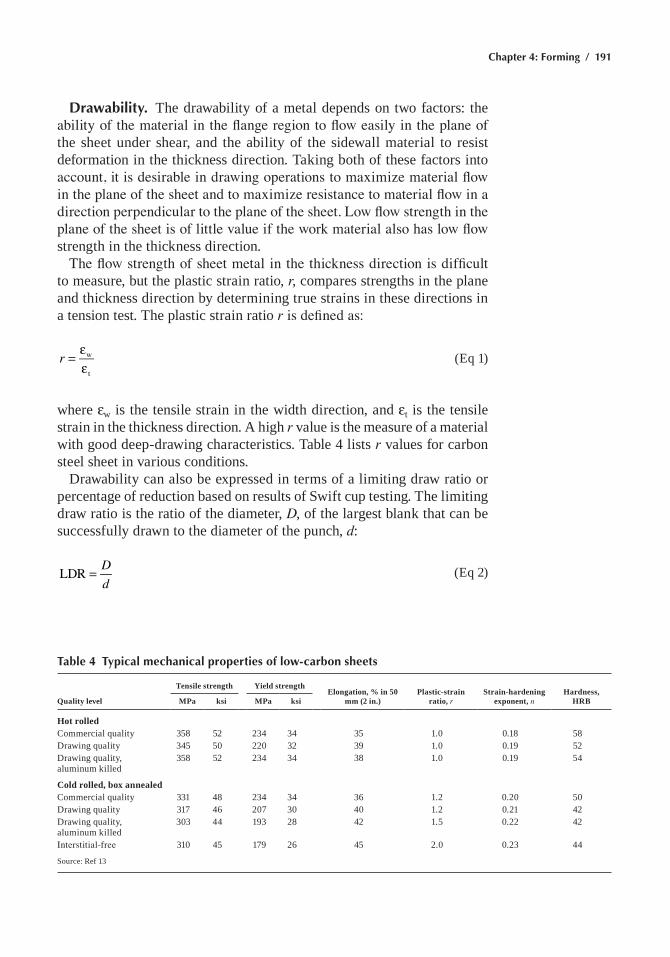
Chapter 4: Forming / 191
Drawability. the drawability of a metal depends on two factors: the ability of the material in the flange region to flow easily in the plane of the sheet under shear, and the ability of the sidewall material to resist deformation in the thickness direction. taking both of these factors into account, it is desirable in drawing operations to maximize material flow in the plane of the sheet and to maximize resistance to material flow in a direction perpendicular to the plane of the sheet. Low flow strength in the plane of the sheet is of little value if the work material also has low flow strength in the thickness direction.
The flow strength of sheet metal in the thickness direction is difficult to measure, but the plastic strain ratio, r, compares strengths in the plane and thickness direction by determining true strains in these directions in a tension test. the plastic strain ratio r is defined as:
=εε
r w
t
(eq 1)
where ew is the tensile strain in the width direction, and et is the tensile strain in the thickness direction. a high r value is the measure of a material with good deep-drawing characteristics. table 4 lists r values for carbon steel sheet in various conditions.
Drawability can also be expressed in terms of a limiting draw ratio or percentage of reduction based on results of Swift cup testing. the limiting draw ratio is the ratio of the diameter, D, of the largest blank that can be successfully drawn to the diameter of the punch, d:
=Dd
LDR
(eq 2)
Table 4 Typical mechanical properties of low-carbon sheets
Tensile strength Yield strengthElongation, % in 50
mm (2 in.)Plastic-strain
ratio, rStrain-hardening
exponent, nHardness,
HRBQuality level MPa ksi MPa ksi
Hot rolledCommercial quality 358 52 234 34 35 1.0 0.18 58Drawing quality 345 50 220 32 39 1.0 0.19 52Drawing quality, aluminum killed
358 52 234 34 38 1.0 0.19 54
Cold rolled, box annealedCommercial quality 331 48 234 34 36 1.2 0.20 50Drawing quality 317 46 207 30 40 1.2 0.21 42Drawing quality, aluminum killed
303 44 193 28 42 1.5 0.22 42
Interstitial-free 310 45 179 26 45 2.0 0.23 44
Source: Ref 13
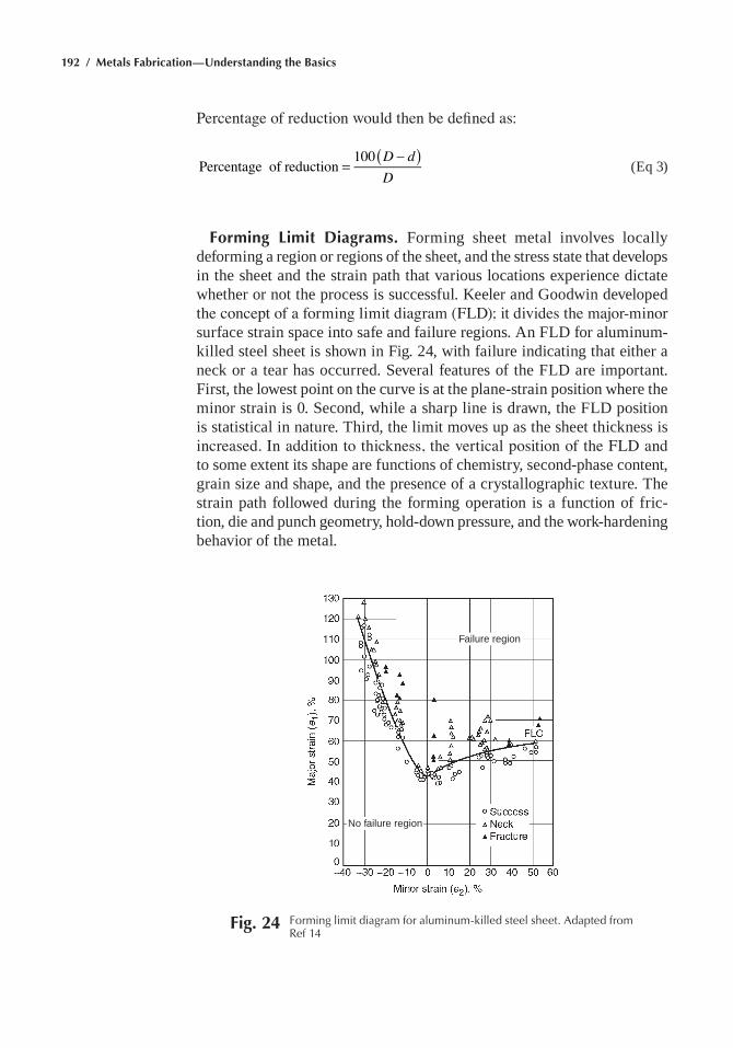
192 / Metals Fabrication—Understanding the Basics
Percentage of reduction would then be defined as:
( )=
−D dD
Percentage of reduction 100 (eq 3)
Forming Limit Diagrams. Forming sheet metal involves locally deforming a region or regions of the sheet, and the stress state that develops in the sheet and the strain path that various locations experience dictate whether or not the process is successful. Keeler and Goodwin developed the concept of a forming limit diagram (FLD); it divides the major-minor surface strain space into safe and failure regions. an FlD for aluminum-killed steel sheet is shown in Fig. 24, with failure indicating that either a neck or a tear has occurred. Several features of the FlD are important. First, the lowest point on the curve is at the plane-strain position where the minor strain is 0. Second, while a sharp line is drawn, the FlD position is statistical in nature. third, the limit moves up as the sheet thickness is increased. In addition to thickness, the vertical position of the FLD and to some extent its shape are functions of chemistry, second-phase content, grain size and shape, and the presence of a crystallographic texture. the strain path followed during the forming operation is a function of fric-tion, die and punch geometry, hold-down pressure, and the work-hardening behavior of the metal.
Failure region
No failure region
Fig. 24 Forming limit diagram for aluminum-killed steel sheet. adapted from ref 14
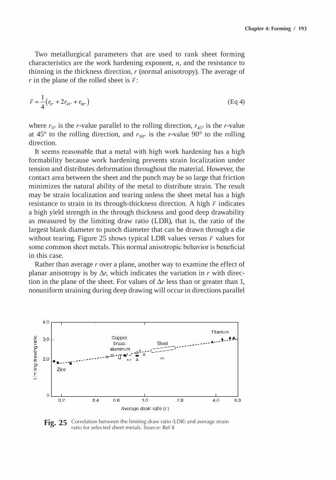
Chapter 4: Forming / 193
two metallurgical parameters that are used to rank sheet forming characteristics are the work hardening exponent, n, and the resistance to thinning in the thickness direction, r (normal anisotropy). the average of r in the plane of the rolled sheet is r :
( )= + +° ° °r r r r14
20 45 90 (eq 4)
where r0° is the r-value parallel to the rolling direction, r45° is the r-value at 45° to the rolling direction, and r90° is the r-value 90° to the rolling direction.
It seems reasonable that a metal with high work hardening has a high formability because work hardening prevents strain localization under tension and distributes deformation throughout the material. however, the contact area between the sheet and the punch may be so large that friction minimizes the natural ability of the metal to distribute strain. the result may be strain localization and tearing unless the sheet metal has a high resistance to strain in its through-thickness direction. a high r indicates a high yield strength in the through thickness and good deep drawability as measured by the limiting draw ratio (lDR), that is, the ratio of the largest blank diameter to punch diameter that can be drawn through a die without tearing. Figure 25 shows typical lDR values versus r values for some common sheet metals. This normal anisotropic behavior is beneficial in this case.
Rather than average r over a plane, another way to examine the effect of planar anisotropy is by Dr, which indicates the variation in r with direc-tion in the plane of the sheet. For values of Dr less than or greater than 1, nonuniform straining during deep drawing will occur in directions parallel
Fig. 25 Correlation between the limiting draw ratio (LDr) and average strain ratio for selected sheet metals. Source: ref 8
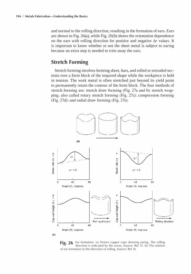
194 / Metals Fabrication—Understanding the Basics
and normal to the rolling direction, resulting in the formation of ears. ears are shown in Fig. 26(a), while Fig. 26(b) shows the orientation dependence on the ears with rolling direction for positive and negative Dr values. It is important to know whether or not the sheet metal is subject to earing because an extra step is needed to trim away the ears.
Stretch Forming
Stretch forming involves forming sheet, bars, and rolled or extruded sec-tions over a form block of the required shape while the workpiece is held in tension. the work metal is often stretched just beyond its yield point to permanently retain the contour of the form block. the four methods of stretch forming are: stretch draw forming (Fig. 27a and b); stretch wrap-ping, also called rotary stretch forming (Fig. 27c); compression forming (Fig. 27d); and radial draw forming (Fig. 27e).
Fig. 26 ear formation. (a) Drawn copper cups showing earing. the rolling direction is indicated by the arrow. Source: ref 15. (b) the relation
of ear formation to the direction of rolling. Source: ref 16
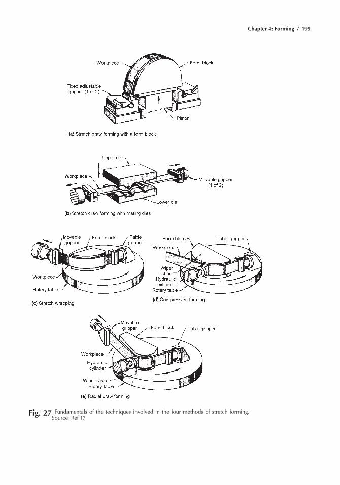
Chapter 4: Forming / 195
Fig. 27 Fundamentals of the techniques involved in the four methods of stretch forming.
Source: ref 17
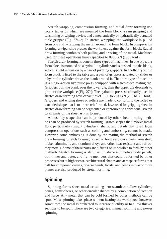
196 / Metals Fabrication—Understanding the Basics
Stretch wrapping, compression forming, and radial draw forming use rotary tables on which are mounted the form block, a ram gripping and tensioning or wiping device, and a mechanically or hydraulically actuated table gripper (Fig. 27c–e). In stretch wrapping, the workpiece is pulled from one end, wrapping the metal around the form block. In compression forming, a wiper shoe presses the workpiece against the form block. Radial draw forming combines both pulling and pressing of the metal. machines used for these operations have capacities to 8900 kN (1000 tonf).
Stretch draw forming is done in three types of machines. In one type, the form block is mounted on a hydraulic cylinder and is pushed into the blank, which is held in tension by a pair of pivoting grippers. In another type, the form block is fixed to the table and a pair of grippers actuated by slides or a hydraulic cylinder draws the blank around it. the third type of machine is a single-action hydraulic press equipped with a two-piece mating die. Grippers pull the blank over the lower die, then the upper die descends to produce the workpiece (Fig. 27b). the hydraulic presses ordinarily used in stretch draw forming have capacities of 1800 to 7100 kN (200 to 800 tonf). Grippers and wiping shoes or rollers are made to conform to the rolled or extruded shape that is to be stretch formed. Jaws used for gripping sheet in stretch draw forming can be segmented or contoured to apply equal stretch to all parts of the sheet as it is formed.
almost any shape that can be produced by other sheet forming meth-ods can be produced by stretch forming. Drawn shapes that involve metal flow, particularly straight cylindrical shells, and details that result from compression operations such as coining and embossing, cannot be made. however, some embossing is done by the mating-die method of stretch draw forming. Stretch forming is used to form aerospace parts from steel, nickel, aluminum, and titanium alloys and other heat-resistant and refrac-tory metals. Some of these parts are difficult or impossible to form by other methods. Stretch forming is also used to shape automotive body panels, both inner and outer, and frame members that could be formed by other processes but at higher cost. architectural shapes and aerospace forms that call for compound curves, reverse bends, twists, and bends in two or more planes are also produced by stretch forming.
Spinning
Spinning forms sheet metal or tubing into seamless hollow cylinders, cones, hemispheres, or other circular shapes by a combination of rotation and force. any metal that can be cold formed by other methods can be spun. Most spinning takes place without heating the workpiece; however, sometimes the metal is preheated to increase ductility or to allow thicker sections to be spun. there are two categories: manual spinning and power spinning.
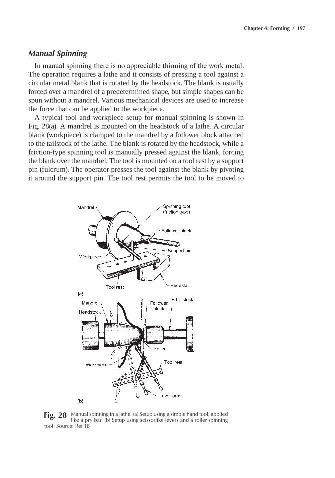
Chapter 4: Forming / 197
Manual Spinning
In manual spinning there is no appreciable thinning of the work metal. the operation requires a lathe and it consists of pressing a tool against a circular metal blank that is rotated by the headstock. the blank is usually forced over a mandrel of a predetermined shape, but simple shapes can be spun without a mandrel. Various mechanical devices are used to increase the force that can be applied to the workpiece.
a typical tool and workpiece setup for manual spinning is shown in Fig. 28(a). a mandrel is mounted on the headstock of a lathe. a circular blank (workpiece) is clamped to the mandrel by a follower block attached to the tailstock of the lathe. the blank is rotated by the headstock, while a friction-type spinning tool is manually pressed against the blank, forcing the blank over the mandrel. the tool is mounted on a tool rest by a support pin (fulcrum). the operator presses the tool against the blank by pivoting it around the support pin. the tool rest permits the tool to be moved to
Fig. 28 Manual spinning in a lathe. (a) Setup using a simple hand tool, applied like a pry bar. (b) Setup using scissorlike levers and a roller spinning
tool. Source: ref 18
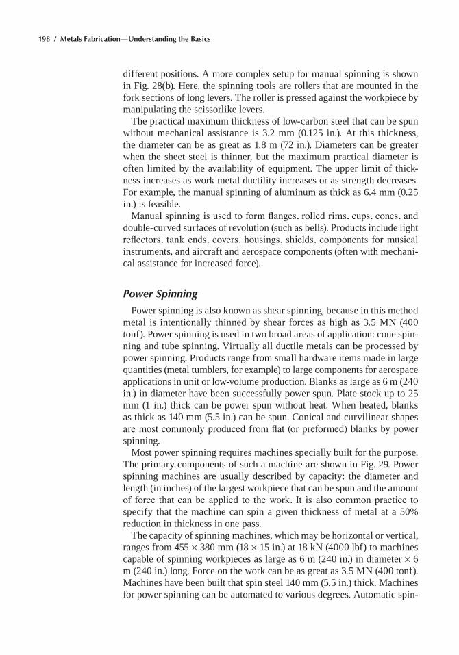
198 / Metals Fabrication—Understanding the Basics
different positions. a more complex setup for manual spinning is shown in Fig. 28(b). here, the spinning tools are rollers that are mounted in the fork sections of long levers. the roller is pressed against the workpiece by manipulating the scissorlike levers.
the practical maximum thickness of low-carbon steel that can be spun without mechanical assistance is 3.2 mm (0.125 in.). at this thickness, the diameter can be as great as 1.8 m (72 in.). Diameters can be greater when the sheet steel is thinner, but the maximum practical diameter is often limited by the availability of equipment. the upper limit of thick-ness increases as work metal ductility increases or as strength decreases. For example, the manual spinning of aluminum as thick as 6.4 mm (0.25 in.) is feasible.
Manual spinning is used to form flanges, rolled rims, cups, cones, and double-curved surfaces of revolution (such as bells). Products include light reflectors, tank ends, covers, housings, shields, components for musical instruments, and aircraft and aerospace components (often with mechani-cal assistance for increased force).
Power Spinning
Power spinning is also known as shear spinning, because in this method metal is intentionally thinned by shear forces as high as 3.5 mN (400 tonf). Power spinning is used in two broad areas of application: cone spin-ning and tube spinning. Virtually all ductile metals can be processed by power spinning. Products range from small hardware items made in large quantities (metal tumblers, for example) to large components for aerospace applications in unit or low-volume production. Blanks as large as 6 m (240 in.) in diameter have been successfully power spun. Plate stock up to 25 mm (1 in.) thick can be power spun without heat. When heated, blanks as thick as 140 mm (5.5 in.) can be spun. Conical and curvilinear shapes are most commonly produced from flat (or preformed) blanks by power spinning.
most power spinning requires machines specially built for the purpose. the primary components of such a machine are shown in Fig. 29. Power spinning machines are usually described by capacity: the diameter and length (in inches) of the largest workpiece that can be spun and the amount of force that can be applied to the work. It is also common practice to specify that the machine can spin a given thickness of metal at a 50% reduction in thickness in one pass.
the capacity of spinning machines, which may be horizontal or vertical, ranges from 455 ¥ 380 mm (18 ¥ 15 in.) at 18 kN (4000 lbf) to machines capable of spinning workpieces as large as 6 m (240 in.) in diameter ¥ 6 m (240 in.) long. Force on the work can be as great as 3.5 mN (400 tonf). machines have been built that spin steel 140 mm (5.5 in.) thick. machines for power spinning can be automated to various degrees. automatic spin-
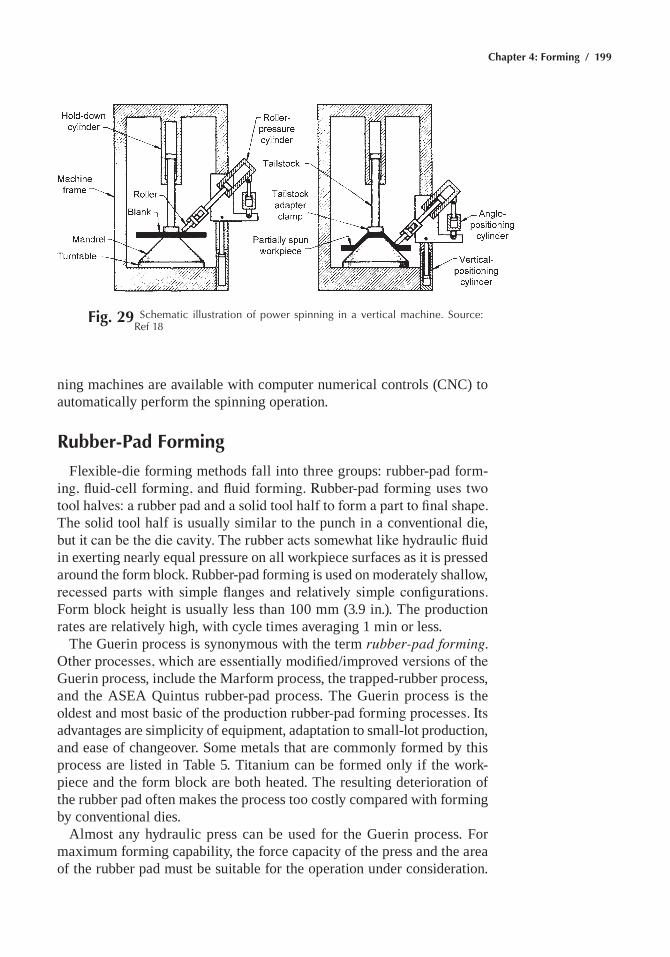
Chapter 4: Forming / 199
ning machines are available with computer numerical controls (CNC) to automatically perform the spinning operation.
Rubber-Pad Forming
Flexible-die forming methods fall into three groups: rubber-pad form-ing, fluid-cell forming, and fluid forming. Rubber-pad forming uses two tool halves: a rubber pad and a solid tool half to form a part to final shape. the solid tool half is usually similar to the punch in a conventional die, but it can be the die cavity. The rubber acts somewhat like hydraulic fluid in exerting nearly equal pressure on all workpiece surfaces as it is pressed around the form block. Rubber-pad forming is used on moderately shallow, recessed parts with simple flanges and relatively simple configurations. Form block height is usually less than 100 mm (3.9 in.). the production rates are relatively high, with cycle times averaging 1 min or less.
the Guerin process is synonymous with the term rubber-pad forming. Other processes, which are essentially modified/improved versions of the Guerin process, include the marform process, the trapped-rubber process, and the aSea Quintus rubber-pad process. the Guerin process is the oldest and most basic of the production rubber-pad forming processes. Its advantages are simplicity of equipment, adaptation to small-lot production, and ease of changeover. Some metals that are commonly formed by this process are listed in table 5. titanium can be formed only if the work-piece and the form block are both heated. the resulting deterioration of the rubber pad often makes the process too costly compared with forming by conventional dies.
almost any hydraulic press can be used for the Guerin process. For maximum forming capability, the force capacity of the press and the area of the rubber pad must be suitable for the operation under consideration.
Fig. 29 Schematic illustration of power spinning in a vertical machine. Source:
ref 18
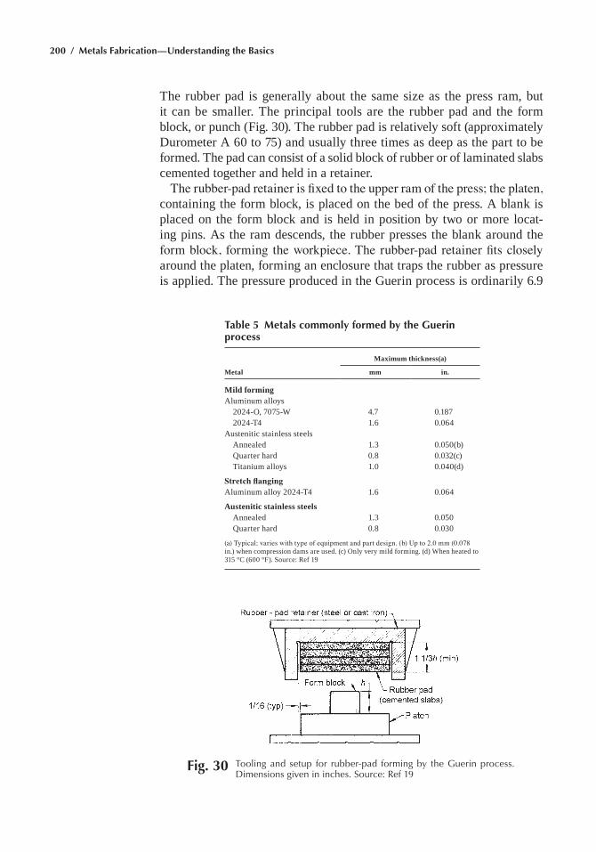
200 / Metals Fabrication—Understanding the Basics
the rubber pad is generally about the same size as the press ram, but it can be smaller. the principal tools are the rubber pad and the form block, or punch (Fig. 30). the rubber pad is relatively soft (approximately Durometer a 60 to 75) and usually three times as deep as the part to be formed. the pad can consist of a solid block of rubber or of laminated slabs cemented together and held in a retainer.
The rubber-pad retainer is fixed to the upper ram of the press; the platen, containing the form block, is placed on the bed of the press. a blank is placed on the form block and is held in position by two or more locat-ing pins. as the ram descends, the rubber presses the blank around the form block, forming the workpiece. The rubber-pad retainer fits closely around the platen, forming an enclosure that traps the rubber as pressure is applied. the pressure produced in the Guerin process is ordinarily 6.9
Table 5 Metals commonly formed by the Guerin process
Metal
Maximum thickness(a)
mm in.
Mild formingaluminum alloys 2024-O, 7075-W 4.7 0.187 2024-t4 1.6 0.064austenitic stainless steels annealed 1.3 0.050(b) Quarter hard 0.8 0.032(c) titanium alloys 1.0 0.040(d)
Stretch flangingaluminum alloy 2024-t4 1.6 0.064
Austenitic stainless steels annealed 1.3 0.050 Quarter hard 0.8 0.030
(a) Typical; varies with type of equipment and part design. (b) Up to 2.0 mm (0.078 in.) when compression dams are used. (c) Only very mild forming. (d) When heated to 315 °C (600 °F). Source: Ref 19
Fig. 30 tooling and setup for rubber-pad forming by the Guerin process. Dimensions given in inches. Source: ref 19
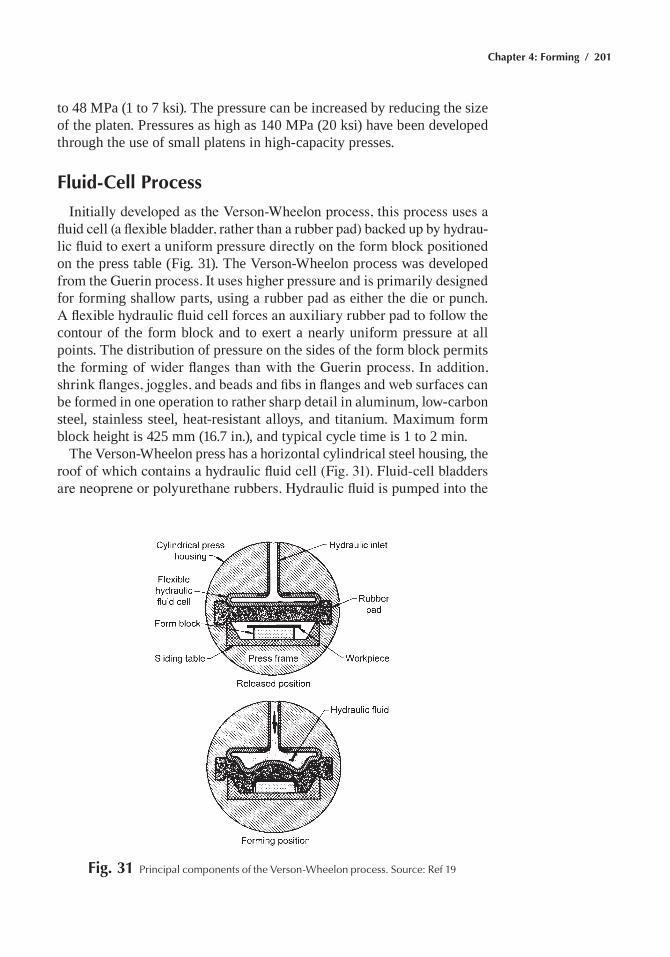
Chapter 4: Forming / 201
to 48 mPa (1 to 7 ksi). the pressure can be increased by reducing the size of the platen. Pressures as high as 140 mPa (20 ksi) have been developed through the use of small platens in high-capacity presses.
Fluid-Cell Process
Initially developed as the Verson-Wheelon process, this process uses a fluid cell (a flexible bladder, rather than a rubber pad) backed up by hydrau-lic fluid to exert a uniform pressure directly on the form block positioned on the press table (Fig. 31). the Verson-Wheelon process was developed from the Guerin process. It uses higher pressure and is primarily designed for forming shallow parts, using a rubber pad as either the die or punch. A flexible hydraulic fluid cell forces an auxiliary rubber pad to follow the contour of the form block and to exert a nearly uniform pressure at all points. the distribution of pressure on the sides of the form block permits the forming of wider flanges than with the Guerin process. In addition, shrink flanges, joggles, and beads and fibs in flanges and web surfaces can be formed in one operation to rather sharp detail in aluminum, low-carbon steel, stainless steel, heat-resistant alloys, and titanium. maximum form block height is 425 mm (16.7 in.), and typical cycle time is 1 to 2 min.
the Verson-Wheelon press has a horizontal cylindrical steel housing, the roof of which contains a hydraulic fluid cell (Fig. 31). Fluid-cell bladders are neoprene or polyurethane rubbers. Hydraulic fluid is pumped into the
Fig. 31 principal components of the Verson-Wheelon process. Source: ref 19
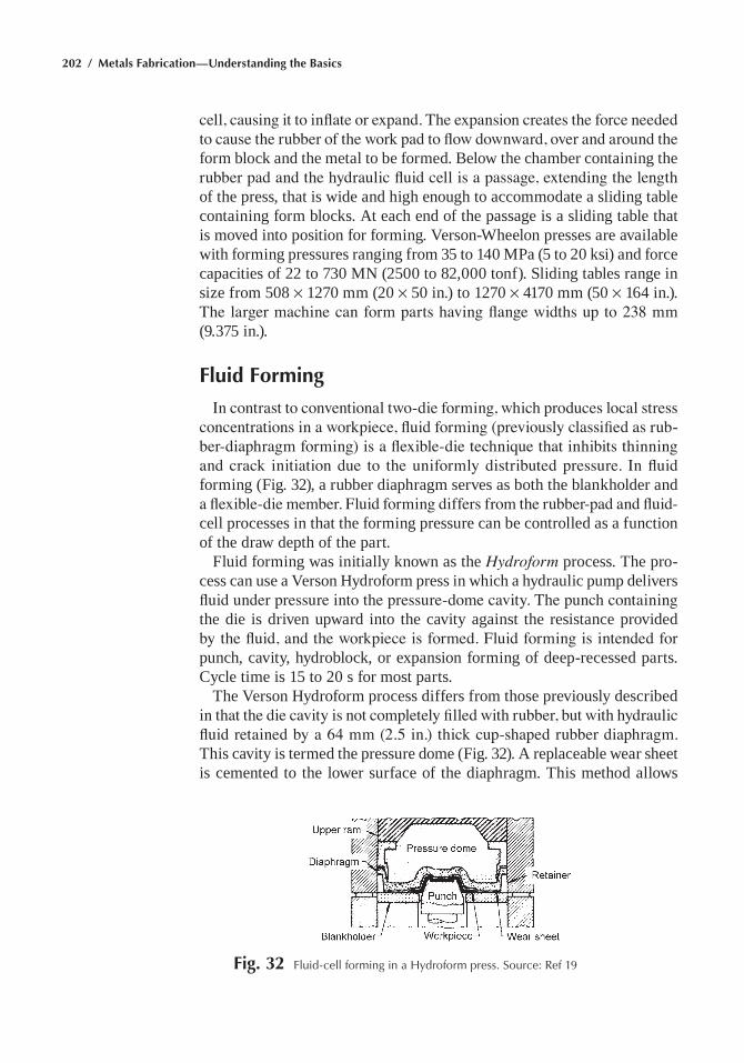
202 / Metals Fabrication—Understanding the Basics
cell, causing it to inflate or expand. The expansion creates the force needed to cause the rubber of the work pad to flow downward, over and around the form block and the metal to be formed. Below the chamber containing the rubber pad and the hydraulic fluid cell is a passage, extending the length of the press, that is wide and high enough to accommodate a sliding table containing form blocks. at each end of the passage is a sliding table that is moved into position for forming. Verson-Wheelon presses are available with forming pressures ranging from 35 to 140 mPa (5 to 20 ksi) and force capacities of 22 to 730 mN (2500 to 82,000 tonf). Sliding tables range in size from 508 ¥ 1270 mm (20 ¥ 50 in.) to 1270 ¥ 4170 mm (50 ¥ 164 in.). The larger machine can form parts having flange widths up to 238 mm (9.375 in.).
Fluid Forming
In contrast to conventional two-die forming, which produces local stress concentrations in a workpiece, fluid forming (previously classified as rub-ber-diaphragm forming) is a flexible-die technique that inhibits thinning and crack initiation due to the uniformly distributed pressure. In fluid forming (Fig. 32), a rubber diaphragm serves as both the blankholder and a flexible-die member. Fluid forming differs from the rubber-pad and fluid-cell processes in that the forming pressure can be controlled as a function of the draw depth of the part.
Fluid forming was initially known as the Hydroform process. the pro-cess can use a Verson hydroform press in which a hydraulic pump delivers fluid under pressure into the pressure-dome cavity. The punch containing the die is driven upward into the cavity against the resistance provided by the fluid, and the workpiece is formed. Fluid forming is intended for punch, cavity, hydroblock, or expansion forming of deep-recessed parts. Cycle time is 15 to 20 s for most parts.
the Verson hydroform process differs from those previously described in that the die cavity is not completely filled with rubber, but with hydraulic fluid retained by a 64 mm (2.5 in.) thick cup-shaped rubber diaphragm. this cavity is termed the pressure dome (Fig. 32). a replaceable wear sheet is cemented to the lower surface of the diaphragm. this method allows
Fig. 32 Fluid-cell forming in a hydroform press. Source: ref 19
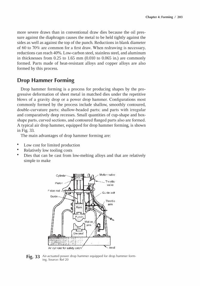
Chapter 4: Forming / 203
more severe draws than in conventional draw dies because the oil pres-sure against the diaphragm causes the metal to be held tightly against the sides as well as against the top of the punch. Reductions in blank diameter of 60 to 70% are common for a first draw. When redrawing is necessary, reductions can reach 40%. low-carbon steel, stainless steel, and aluminum in thicknesses from 0.25 to 1.65 mm (0.010 to 0.065 in.) are commonly formed. Parts made of heat-resistant alloys and copper alloys are also formed by this process.
Drop Hammer Forming
Drop hammer forming is a process for producing shapes by the pro-gressive deformation of sheet metal in matched dies under the repetitive blows of a gravity drop or a power drop hammer. Configurations most commonly formed by the process include shallow, smoothly contoured, double-curvature parts; shallow-beaded parts; and parts with irregular and comparatively deep recesses. Small quantities of cup-shape and box-shape parts, curved sections, and contoured flanged parts also are formed. a typical air drop hammer, equipped for drop hammer forming, is shown in Fig. 33.
the main advantages of drop hammer forming are:
• low cost for limited production• Relatively low tooling costs• Dies that can be cast from low-melting alloys and that are relatively
simple to make
Fig. 33 air-actuated power drop hammer equipped for drop hammer form-ing. Source: ref 20
204 / Metals Fabrication—Understanding the Basics
• Short delivery time of product because of simplicity of toolmaking• the possibility of combining coining with forming
against these advantages, the following limitations must be weighed:
• Probability of forming wrinkles• Need for skilled operators, specially trained for this process• Restriction to relatively shallow parts with generous radii• Restriction to relatively thin sheet, from approximately 0.61 to 1.6 mm
(0.024 to 0.064 in.); thicker sheet can be formed only if the parts are shallow and have generous radii.
• Drop hammer forming is not a precision forming method; tolerances of less than 0.8 to 1.6 mm (0.031 to 0.063 in.) are not practical.
Electromagnetic Forming (EMF)
electromagnetic forming is used to both join and shape metals and other materials rapidly and precisely, and without the heat effects and tool marks associated with other techniques. also known as magnetic pulse form-ing, emF uses the direct application of a pressure created by an intense, transient magnetic field. Without mechanical contact, a metal workpiece is formed by the passage of a pulse of electric current through a forming coil.
In its simplest form, EMF uses a capacitor bank, a forming coil, a field shaper, and an electrically conductive workpiece to create intense mag-netic fields. This intense magnetic field, produced by the discharge of a bank of capacitors into a forming coil, lasts only a few microseconds. the resulting eddy currents that are induced in the conductive workpiece that is placed close to the coil interact with the magnetic field to cause mutual repulsion between the workpiece and the forming coil. the force of this repulsion is sufficient to cause permanent deformation.
the basic circuit (Fig. 34) used for electromagnetic compression form-ing of a tubular workpiece consists of a forming coil, an energy-storage capacitor, switches, and a power supply of nearly constant current to charge the capacitor. Figure 34(a) shows the flux-density pattern of the magnetic field produced by discharging the capacitor through the forming coil in the absence of an electrically conductive workpiece. The evenly spaced flux lines indicate a uniform flux density within the coil. Figure 34(b) shows the change in field pattern that results when the capacitor is discharged through a forming coil in which a tubular workpiece of highly conductive metal has been inserted. The magnetic field is distorted and the flux den-sity intensified (flux lines are more closely spaced) by confinement to the small annular space between the coil and the workpiece.
Field shapers, which are massive current-carrying conductors induc-tively coupled to the forming coil, concentrate the magnetic field at the point at which forming is desired. This technique most efficiently uses
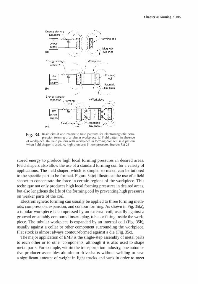
Chapter 4: Forming / 205
stored energy to produce high local forming pressures in desired areas. Field shapers also allow the use of a standard forming coil for a variety of applications. The field shaper, which is simpler to make, can be tailored to the specific part to be formed. Figure 34(c) illustrates the use of a field shaper to concentrate the force in certain regions of the workpiece. this technique not only produces high local forming pressures in desired areas, but also lengthens the life of the forming coil by preventing high pressures on weaker parts of the coil.
electromagnetic forming can usually be applied to three forming meth-ods: compression, expansion, and contour forming. as shown in Fig. 35(a), a tubular workpiece is compressed by an external coil, usually against a grooved or suitably contoured insert, plug, tube, or fitting inside the work-piece. the tubular workpiece is expanded by an internal coil (Fig. 35b), usually against a collar or other component surrounding the workpiece. Flat stock is almost always contour-formed against a die (Fig. 35c).
the major application of emF is the single-step assembly of metal parts to each other or to other components, although it is also used to shape metal parts. For example, within the transportation industry, one automo-tive producer assembles aluminum driveshafts without welding to save a significant amount of weight in light trucks and vans in order to meet
Fig. 34 Basic circuit and magnetic field patterns for electromagnetic com-pression forming of a tubular workpiece. (a) Field pattern in absence
of workpiece. (b) Field pattern with workpiece in forming coil. (c) Field pattern when field shaper is used. a, high pressure; B, low pressure. Source: ref 21
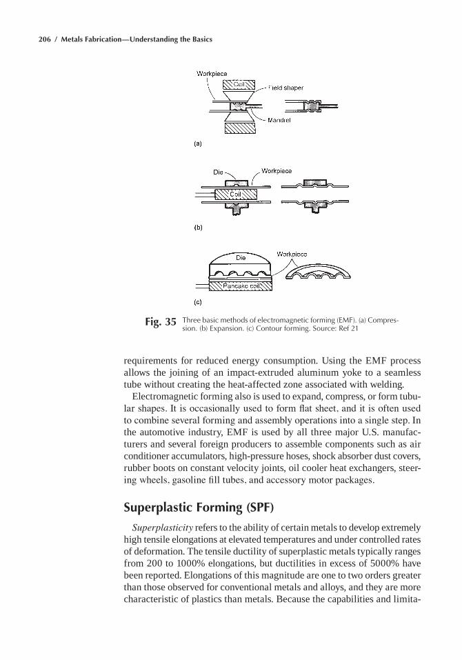
206 / Metals Fabrication—Understanding the Basics
requirements for reduced energy consumption. Using the emF process allows the joining of an impact-extruded aluminum yoke to a seamless tube without creating the heat-affected zone associated with welding.
electromagnetic forming also is used to expand, compress, or form tubu-lar shapes. It is occasionally used to form flat sheet, and it is often used to combine several forming and assembly operations into a single step. In the automotive industry, emF is used by all three major U.S. manufac-turers and several foreign producers to assemble components such as air conditioner accumulators, high-pressure hoses, shock absorber dust covers, rubber boots on constant velocity joints, oil cooler heat exchangers, steer-ing wheels, gasoline fill tubes, and accessory motor packages.
Superplastic Forming (SPF)
Superplasticity refers to the ability of certain metals to develop extremely high tensile elongations at elevated temperatures and under controlled rates of deformation. the tensile ductility of superplastic metals typically ranges from 200 to 1000% elongations, but ductilities in excess of 5000% have been reported. elongations of this magnitude are one to two orders greater than those observed for conventional metals and alloys, and they are more characteristic of plastics than metals. Because the capabilities and limita-
Fig. 35 three basic methods of electromagnetic forming (eMF). (a) Compres-sion. (b) expansion. (c) Contour forming. Source: ref 21
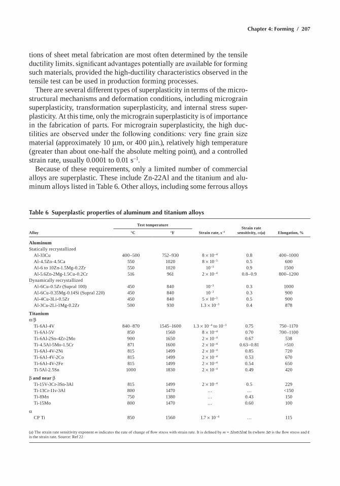
Chapter 4: Forming / 207
tions of sheet metal fabrication are most often determined by the tensile ductility limits, significant advantages potentially are available for forming such materials, provided the high-ductility characteristics observed in the tensile test can be used in production forming processes.
there are several different types of superplasticity in terms of the micro-structural mechanisms and deformation conditions, including micrograin superplasticity, transformation superplasticity, and internal stress super-plasticity. at this time, only the micrograin superplasticity is of importance in the fabrication of parts. For micrograin superplasticity, the high duc-tilities are observed under the following conditions: very fine grain size material (approximately 10 mm, or 400 min.), relatively high temperature (greater than about one-half the absolute melting point), and a controlled strain rate, usually 0.0001 to 0.01 s–1.
Because of these requirements, only a limited number of commercial alloys are superplastic. these include Zn-22al and the titanium and alu-minum alloys listed in table 6. Other alloys, including some ferrous alloys
Table 6 Superplastic properties of aluminum and titanium alloys
Alloy
Test temperature
Strain rate, s–1Strain rate
sensitivity, m(a) Elongation, %°C °F
AluminumStatically recrystallized al-33Cu 400–500 752–930 8 ¥ 10–4 0.8 400–1000 al-4.5Zn-4.5Ca 550 1020 8 ¥ 10–3 0.5 600 al-6 to 10Zn-1.5mg-0.2Zr 550 1020 10–3 0.9 1500 al-5.6Zn-2mg-1.5Cu-0.2Cr 516 961 2 ¥ 10–4 0.8–0.9 800–1200Dynamically recrystallized al-6Cu-0.5Zr (Supral 100) 450 840 10–3 0.3 1000 al-6Cu-0.35mg-0.14Si (Supral 220) 450 840 10–3 0.3 900 al-4Cu-3li-0.5Zr 450 840 5 ¥ 10–3 0.5 900 al-3Cu-2li-1mg-0.2Zr 500 930 1.3 ¥ 10–3 0.4 878
Titaniumα/b ti-6al-4V 840–870 1545–1600 1.3 ¥ 10–4 to 10–3 0.75 750–1170 ti-6al-5V 850 1560 8 ¥ 10–4 0.70 700–1100 ti-6al-2Sn-4Zr-2mo 900 1650 2 ¥ 10–4 0.67 538 ti-4.5al-5mo-1.5Cr 871 1600 2 ¥ 10–4 0.63–0.81 >510 ti-6al-4V-2Ni 815 1499 2 ¥ 10–4 0.85 720 ti-6al-4V-2Co 815 1499 2 ¥ 10–4 0.53 670 ti-6al-4V-2Fe 815 1499 2 ¥ 10–4 0.54 650 ti-5al-2.5Sn 1000 1830 2 ¥ 10–4 0.49 420
b and near b ti-15V-3Cr-3Sn-3al 815 1499 2 ¥ 10–4 0.5 229 ti-13Cr-11v-3al 800 1470 … … <150 ti-8mn 750 1380 … 0.43 150 ti-15mo 800 1470 … 0.60 100
α CP ti 850 1560 1.7 ¥ 10–4 … 115
(a) the strain rate sensitivity exponent m indicates the rate of change of flow stress with strain rate. It is defined by m = Dlnσ/Dlne In ewhere Dσ is the flow stress and e is the strain rate. Source: Ref 22
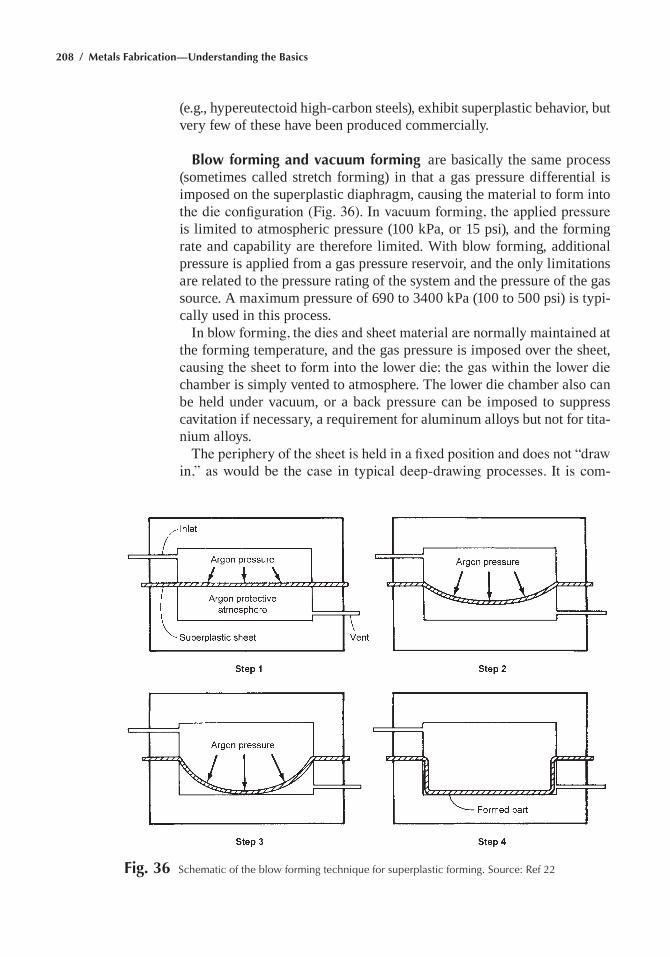
208 / Metals Fabrication—Understanding the Basics
(e.g., hypereutectoid high-carbon steels), exhibit superplastic behavior, but very few of these have been produced commercially.
Blow forming and vacuum forming are basically the same process (sometimes called stretch forming) in that a gas pressure differential is imposed on the superplastic diaphragm, causing the material to form into the die configuration (Fig. 36). In vacuum forming, the applied pressure is limited to atmospheric pressure (100 kPa, or 15 psi), and the forming rate and capability are therefore limited. With blow forming, additional pressure is applied from a gas pressure reservoir, and the only limitations are related to the pressure rating of the system and the pressure of the gas source. a maximum pressure of 690 to 3400 kPa (100 to 500 psi) is typi-cally used in this process.
In blow forming, the dies and sheet material are normally maintained at the forming temperature, and the gas pressure is imposed over the sheet, causing the sheet to form into the lower die; the gas within the lower die chamber is simply vented to atmosphere. the lower die chamber also can be held under vacuum, or a back pressure can be imposed to suppress cavitation if necessary, a requirement for aluminum alloys but not for tita-nium alloys.
The periphery of the sheet is held in a fixed position and does not “draw in,” as would be the case in typical deep-drawing processes. It is com-
Fig. 36 Schematic of the blow forming technique for superplastic forming. Source: ref 22
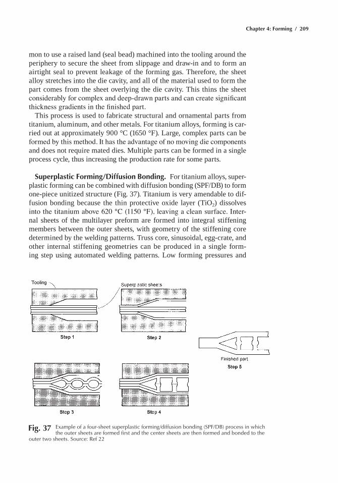
Chapter 4: Forming / 209
mon to use a raised land (seal bead) machined into the tooling around the periphery to secure the sheet from slippage and draw-in and to form an airtight seal to prevent leakage of the forming gas. therefore, the sheet alloy stretches into the die cavity, and all of the material used to form the part comes from the sheet overlying the die cavity. this thins the sheet considerably for complex and deep-drawn parts and can create significant thickness gradients in the finished part.
this process is used to fabricate structural and ornamental parts from titanium, aluminum, and other metals. For titanium alloys, forming is car-ried out at approximately 900 °C (1650 °F). large, complex parts can be formed by this method. It has the advantage of no moving die components and does not require mated dies. multiple parts can be formed in a single process cycle, thus increasing the production rate for some parts.
Superplastic Forming/Diffusion Bonding. For titanium alloys, super-plastic forming can be combined with diffusion bonding (SPF/DB) to form one-piece unitized structure (Fig. 37). titanium is very amendable to dif-fusion bonding because the thin protective oxide layer (tiO2) dissolves into the titanium above 620 °C (1150 °F), leaving a clean surface. Inter-nal sheets of the multilayer preform are formed into integral stiffening members between the outer sheets, with geometry of the stiffening core determined by the welding patterns. truss core, sinusoidal, egg-crate, and other internal stiffening geometries can be produced in a single form-ing step using automated welding patterns. low forming pressures and
Fig. 37 example of a four-sheet superplastic forming/diffusion bonding (SpF/DB) process in which the outer sheets are formed first and the center sheets are then formed and bonded to the
outer two sheets. Source: ref 22
210 / Metals Fabrication—Understanding the Basics
single-step processing significantly reduce tooling costs compared to con-ventional methods. however, the aluminum oxide (al2O3) on aluminum does not dissolve and must either be removed, or ruptured, to promote diffusion bonding. although diffusion bonding of aluminum alloys has successfully been demonstrated in the laboratory, SPF/DB of aluminum alloys is not yet a commercial process.
ACKNOWLEDGMENT
this chapter was adapted from Forming in Metals Handbook Desk Edi-tion, 2nd ed., ASM International, 1998.
REFERENCES
1. Shearing, Slitting, and Cutting, Metals Handbook Desk Edition, 2nd ed., ASM International, 1998
2. Selection of Die materials for Sheet metal Forming, Metals Hand-book Desk Edition, 2nd ed., ASM International, 1998
3. Selection and Use of lubricants in Sheet metal Forming, Metals Handbook Desk Edition, 2nd ed., ASM International, 1998
4. Blanking of low-Carbon Steel, Metals Handbook Desk Edition, 2nd ed., ASM International, 1998
5. Piercing of low-Carbon Steel, Metals Handbook Desk Edition, 2nd ed., ASM International, 1998
6. Fine-edge Blanking and Piercing, Metals Handbook Desk Edition, 2nd ed., ASM International, 1998
7. a.C. Reardon, Metallurgy for the Non-Metallurgist, 2nd ed., aSm International, 2011
8. G.e. Deiter, Mechanical Metallurgy, 3rd ed., mcGraw-hill, 1986 9. B. l. Ferguson, Design for Deformation Processes, Materials Selec-
tion and Design, Vol 20, ASM Handbook, 199710. m. ahmetoglu, t. Broek, G. Kinzel, t. altan, and K. Chandorkar,
Deep Drawing of Rectangular Pans from aluminum alloy 2008-t4, paper 950694, Society of automotive engineers, 1995
11. Press Bending of low-Carbon Steel, Metals Handbook Desk Edi-tion, 2nd ed., ASM International, 1998
12. Press-Brake Forming, Metals Handbook Desk Edition, 2nd ed., aSm International, 1998
13. Deep Drawing, Metals Handbook Desk Edition, 2nd ed., ASM Inter-national, 1998
14. S. hecker, Proc. 7th Biennial Congress of Int. Deep Drawing Research Group, amsterdam, 9–10 Oct 1972
15. D.V. Wilson and R.D. Butler, J. Inst. Metals, 1961–1962, p 473–48316. W.F. hosford and R.m. Caddell, Metal Forming: Mechanics and
Metallurgy, 2nd ed., Prentice-hall, 1993, p 268
Chapter 4: Forming / 211
17. Stretch Forming, Metals Handbook Desk Edition, 2nd ed., aSm International, 1998
18. Spinning, Metals Handbook Desk Edition, 2nd ed., ASM Interna-tional, 1998
19. Rubber-Pad Forming, Metals Handbook Desk Edition, 2nd ed., aSm International, 1998
20. Drop hammer Forming, Metals Handbook Desk Edition, 2nd ed., ASM International, 1998
21. electromagnetic Forming, Metals Handbook Desk Edition, 2nd ed., ASM International, 1998
22. Superplastic Forming (SPF), Metals Handbook Desk Edition, 2nd ed., ASM International, 1998
SELECTED REFERENCES• t. altan and a.e. tekkaya, Sheet Metal Forming Processes and Appli-
cations, ASM International, 2012• G.D. lascoe, Handbook of Fabrication Processes, ASM International,
1988• e. mielnik, Metalworking Science and Engineering, mcGraw-hill,
1991• C. Wick, J.t. Benedict, and R.F. Veilleux, ed., Forming, Vol 2, Tool
and Manufacturing Engineers Handbook, 4th ed., Society of manu-facturing engineers, 1984
Copyright © 2013 ASM International®
All rights reservedwww.asminternational.org
Metals Fabrication—Understanding the BasicsF.C. Campbell, editor
Chapter 5Machining
Machining covers a large number of manufacturing processes designed to remove unwanted material, usually in the form of chips, from a workpiece. Machining is used to convert castings, forgings, and preformed blocks of metal into desired shapes, with a specified size and surface finish. Almost every manufactured product has components that require machining, often to great precision. Therefore, machining is one of the most important of the basic manufacturing processes because of the value added to the final product. By the same token, machining processes are often the most expensive.
Types of Machining Processes
Four important machining processes (turning, milling, drilling, and grinding) are illustrated in Fig. 1. There are three basic classes of machin-ing operations: conventional, abrasive, and nontraditional.
Conventional machining operations include turning, drilling, mill-ing, boring, broaching, planing, shaping, reaming, and tapping. in these operations, material is removed from the workpiece in the form of a chip, which for metal parts is produced through plastic deformation.
In abrasive processes, such as grinding, honing, and lapping, small particles are removed from the workpiece by abrasion with a hard tool. abrasive processes have lower material removal rates and higher energy requirements than conventional processes but can produce closer toler-ances and finer surface finishes.
Nontraditional machining processes include processes such as elec-trical discharge machining (eDM), electrochemical machining (ecM), ultrasonic machining (UsM), and chemical milling (cM). in these opera-tions, material is removed by a variety of physical mechanisms (Table 1),
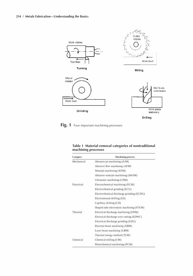
214 / Metals Fabrication—Understanding the Basics
Fig. 1 Four important machining processes
Table 1 Material removal categories of nontraditional machining processes
Category Machining process
Mechanical abrasive jet machining (aJM)
Abrasive flow machining (AFM)
Waterjet machining (WJM)
abrasive waterjet machining (aWJM)
Ultrasonic machining (UsM)
electrical electrochemical machining (ecM)
electrochemical grinding (ecg)
electrochemical discharge grinding (ecDg)
electrostream drilling (es)
capillary drilling (cD)
shaped tube electrolytic machining (sTeM)
Thermal electrical discharge machining (eDM)
electrical discharge wire cutting (eDWc)
electrical discharge grinding (eDg)
Electron beam machining (EBM)
Laser beam machining (LBM)
Thermal energy method (TeM)
chemical chemical milling (cM)
Photochemical machining (PcM)
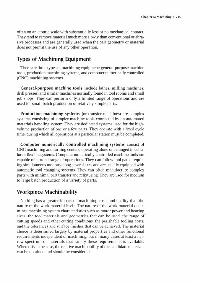
Chapter 5: Machining / 215
often on an atomic scale with substantially less or no mechanical contact. They tend to remove material much more slowly than conventional or abra-sive processes and are generally used when the part geometry or material does not permit the use of any other operation.
Types of Machining Equipment
There are three types of machining equipment: general-purpose machine tools, production machining systems, and computer numerically controlled (cnc) machining systems.
General-purpose machine tools include lathes, milling machines, drill presses, and similar machines normally found in tool rooms and small job shops. They can perform only a limited range of operations and are used for small batch production of relatively simple parts.
Production machining systems (or transfer machines) are complex systems consisting of simpler machine tools connected by an automated materials handling system. They are dedicated systems used for the high-volume production of one or a few parts. They operate with a fixed cycle time, during which all operations at a particular station must be completed.
Computer numerically controlled machining systems consist of cnc machining and turning centers, operating alone or arranged in cellu-lar or flexible systems. Computer numerically controlled machine tools are capable of a broad range of operations. They can follow tool paths requir-ing simultaneous motions along several axes and are usually equipped with automatic tool changing systems. They can often manufacture complex parts with minimal part transfer and refixturing. They are used for medium to large batch production of a variety of parts.
Workpiece Machinability
nothing has a greater impact on machining costs and quality than the nature of the work material itself. The nature of the work material deter-mines machining system characteristics such as motor power and bearing sizes, the tool materials and geometries that can be used, the range of cutting speeds and other cutting conditions, the perishable tooling costs, and the tolerances and surface finishes that can be achieved. The material choice is determined largely by material properties and other functional requirements independent of machining, but in many cases at least a nar-row spectrum of materials that satisfy these requirements is available. When this is the case, the relative machinability of the candidate materials can be obtained and should be considered.
216 / Metals Fabrication—Understanding the Basics
Machinability is a loosely defined term reflecting the ease with which materials can be machined. in most cases tool wear rates or tool life under typical conditions are the most significant practical constraints on machin-ing operations, and in practice, most tables of machinability ratings are based on tool life test results. For example, a reference material such as 1212 steel may be assigned a rating of 100, and ratings for other materi-als are computed from ratios of tool lives obtained with the material in question and the reference material in a standardized test. Other criteria used to rank material machinability include machining forces and power consumption, chip form, and achievable surface finish.
Machinability varies most significantly between different material classes or base chemistries. The common classes of metallic work materi-als, in order of decreasing machinability, include:
• Magnesium alloys• aluminum alloys• copper alloys• gray irons• nodular irons• carbon steels• Low-alloy steels• stainless steels• hardened and high-alloy steels• nickel-base superalloys• Titanium alloys
if machinability is a primary consideration, materials from classes higher on this list should be substituted for those lower on the list, if possible.
Machinability generally decreases with increasing penetration hardness and yield strength and with increasing ductility. homogeneous materials with fine grain structures are easier to machine than non-uniform materi-als or materials with coarse grain structures. annealing and tempering also usually increase machinability, although annealed materials are more prone to chip-control problems. hard alloying elements such as chromium, nickel, and silicon typically reduce machinability. Metal-matrix compos-ites are generally less machinable than their base-matrix metal. similarly, powder metals are less machinable than cast or wrought alloys of equiva-lent chemistry.
Most material classes include “free-machining” alloys, which contain alloy additions that increase tool life or chip formation characteristics. Free-machining additives are typically substances that form inclusions in the matrix that serve to break chips and provide internal lubrication; examples include lead in brasses and steels, sulfur compounds in steels and powder metals, and insoluble metals such as bismuth, selenium, and tellurium in steels. however, the addition of free-machining additives
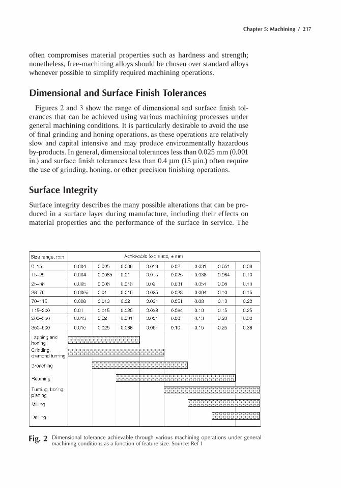
Chapter 5: Machining / 217
often compromises material properties such as hardness and strength; nonetheless, free-machining alloys should be chosen over standard alloys whenever possible to simplify required machining operations.
Dimensional and Surface Finish Tolerances
Figures 2 and 3 show the range of dimensional and surface finish tol-erances that can be achieved using various machining processes under general machining conditions. it is particularly desirable to avoid the use of final grinding and honing operations, as these operations are relatively slow and capital intensive and may produce environmentally hazardous by-products. in general, dimensional tolerances less than 0.025 mm (0.001 in.) and surface finish tolerances less than 0.4 mm (15 min.) often require the use of grinding, honing, or other precision finishing operations.
Surface Integrity
surface integrity describes the many possible alterations that can be pro-duced in a surface layer during manufacture, including their effects on material properties and the performance of the surface in service. The
Fig. 2 Dimensional tolerance achievable through various machining operations under general machining conditions as a function of feature size. Source: ref 1
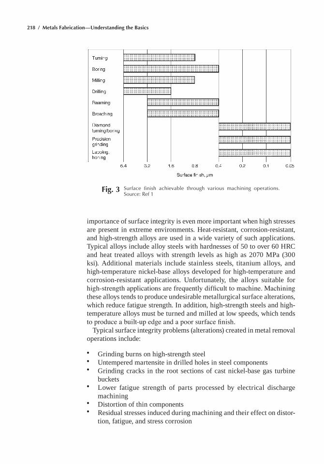
218 / Metals Fabrication—Understanding the Basics
importance of surface integrity is even more important when high stresses are present in extreme environments. heat-resistant, corrosion-resistant, and high-strength alloys are used in a wide variety of such applications. Typical alloys include alloy steels with hardnesses of 50 to over 60 hrc and heat treated alloys with strength levels as high as 2070 MPa (300 ksi). additional materials include stainless steels, titanium alloys, and high-temperature nickel-base alloys developed for high-temperature and corrosion-resistant applications. Unfortunately, the alloys suitable for high-strength applications are frequently difficult to machine. Machining these alloys tends to produce undesirable metallurgical surface alterations, which reduce fatigue strength. in addition, high-strength steels and high-temperature alloys must be turned and milled at low speeds, which tends to produce a built-up edge and a poor surface finish.
Typical surface integrity problems (alterations) created in metal removal operations include:
• grinding burns on high-strength steel• Untempered martensite in drilled holes in steel components• grinding cracks in the root sections of cast nickel-base gas turbine
buckets• Lower fatigue strength of parts processed by electrical discharge
machining• Distortion of thin components• residual stresses induced during machining and their effect on distor-
tion, fatigue, and stress corrosion
Fig. 3 Surface finish achievable through various machining operations. Source: ref 1
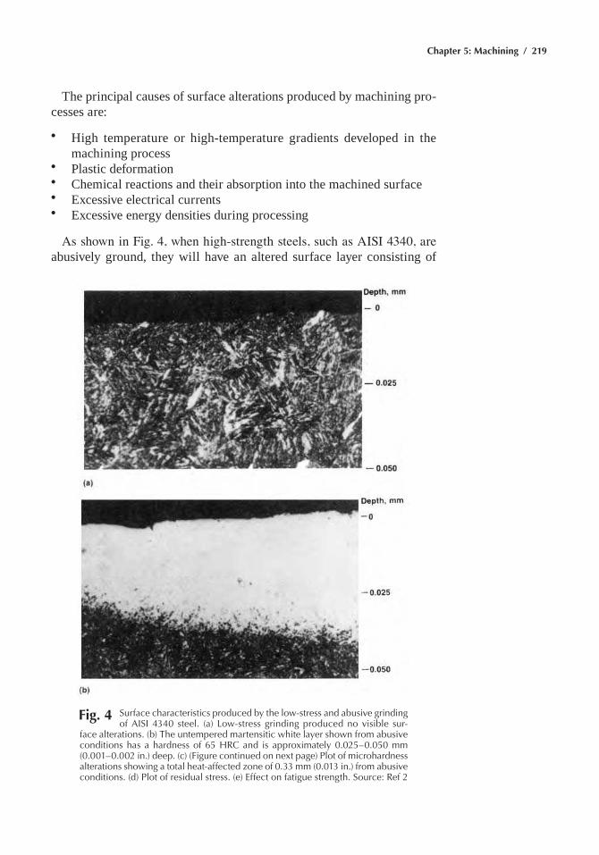
Chapter 5: Machining / 219
The principal causes of surface alterations produced by machining pro-cesses are:
• high temperature or high-temperature gradients developed in the machining process
• Plastic deformation• chemical reactions and their absorption into the machined surface• excessive electrical currents• excessive energy densities during processing
As shown in Fig. 4, when high-strength steels, such as AISI 4340, are abusively ground, they will have an altered surface layer consisting of
Fig. 4 Surface characteristics produced by the low-stress and abusive grinding of aISI 4340 steel. (a) Low-stress grinding produced no visible sur-
face alterations. (b) the untempered martensitic white layer shown from abusive conditions has a hardness of 65 hrC and is approximately 0.025–0.050 mm (0.001–0.002 in.) deep. (c) (Figure continued on next page) plot of microhardness alterations showing a total heat-affected zone of 0.33 mm (0.013 in.) from abusive conditions. (d) plot of residual stress. (e) effect on fatigue strength. Source: ref 2
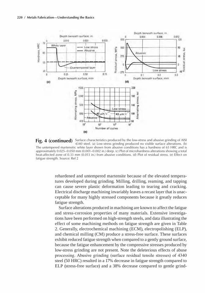
220 / Metals Fabrication—Understanding the Basics
Fig. 4 (continued) Surface characteristics produced by the low-stress and abusive grinding of aISI 4340 steel. (a) Low-stress grinding produced no visible surface alterations. (b)
the untempered martensitic white layer shown from abusive conditions has a hardness of 65 hrC and is approximately 0.025–0.050 mm (0.001–0.002 in.) deep. (c) plot of microhardness alterations showing a total heat-affected zone of 0.33 mm (0.013 in.) from abusive conditions. (d) plot of residual stress. (e) effect on fatigue strength. Source: ref 2
rehardened and untempered martensite because of the elevated tempera-tures developed during grinding. Milling, drilling, reaming, and tapping can cause severe plastic deformation leading to tearing and cracking. electrical discharge machining invariably leaves a recast layer that is unac-ceptable for many highly stressed components because it greatly reduces fatigue strength.
surface alterations produced in machining are known to affect the fatigue and stress-corrosion properties of many materials. extensive investiga-tions have been performed on high-strength steels, and data illustrating the effect of some machining methods on fatigue strength are given in Table 2. generally, electrochemical machining (ecM), electropolishing (eLP), and chemical milling (cM) produce a stress-free surface. These surfaces exhibit reduced fatigue strength when compared to a gently ground surface, because the fatigue enhancement by the compressive stresses produced by low-stress grinding are not present. note the deleterious effects of abuse processing. Abusive grinding (surface residual tensile stresses) of 4340 steel (50 hrc) resulted in a 17% decrease in fatigue strength compared to eLP (stress-free surface) and a 38% decrease compared to gentle grind-
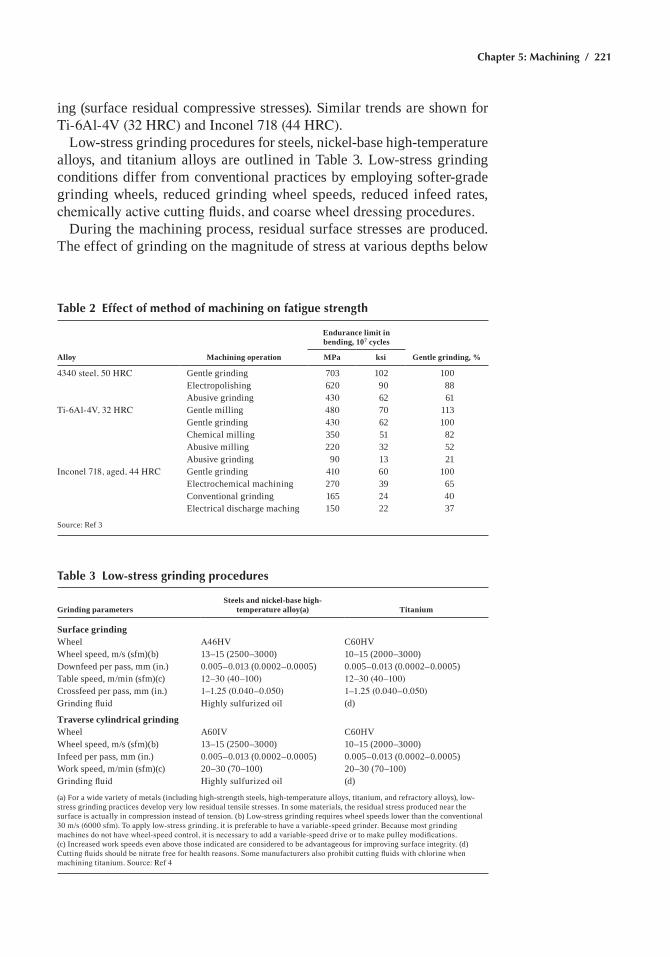
Chapter 5: Machining / 221
ing (surface residual compressive stresses). similar trends are shown for Ti-6Al-4V (32 HRC) and Inconel 718 (44 HRC).
Low-stress grinding procedures for steels, nickel-base high-temperature alloys, and titanium alloys are outlined in Table 3. Low-stress grinding conditions differ from conventional practices by employing softer-grade grinding wheels, reduced grinding wheel speeds, reduced infeed rates, chemically active cutting fluids, and coarse wheel dressing procedures.
During the machining process, residual surface stresses are produced. The effect of grinding on the magnitude of stress at various depths below
Table 2 Effect of method of machining on fatigue strength
Alloy Machining operation
Endurance limit in bending, 107 cycles
Gentle grinding, %MPa ksi
4340 steel, 50 HRC gentle grinding 703 102 100electropolishing 620 90 88abusive grinding 430 62 61
Ti-6Al-4V, 32 HRC gentle milling 480 70 113gentle grinding 430 62 100chemical milling 350 51 82abusive milling 220 32 52abusive grinding 90 13 21
Inconel 718, aged, 44 HRC gentle grinding 410 60 100electrochemical machining 270 39 65conventional grinding 165 24 40electrical discharge maching 150 22 37
source: ref 3
Table 3 Low-stress grinding procedures
Grinding parametersSteels and nickel-base high-
temperature alloy(a) Titanium
Surface grindingWheel A46HV c60hvWheel speed, m/s (sfm)(b) 13–15 (2500–3000) 10–15 (2000–3000)Downfeed per pass, mm (in.) 0.005–0.013 (0.0002–0.0005) 0.005–0.013 (0.0002–0.0005)Table speed, m/min (sfm)(c) 12–30 (40–100) 12–30 (40–100)crossfeed per pass, mm (in.) 1–1.25 (0.040–0.050) 1–1.25 (0.040–0.050)Grinding fluid Highly sulfurized oil (d)
Traverse cylindrical grindingWheel a60iv c60hvWheel speed, m/s (sfm)(b) 13–15 (2500–3000) 10–15 (2000–3000)infeed per pass, mm (in.) 0.005–0.013 (0.0002–0.0005) 0.005–0.013 (0.0002–0.0005)Work speed, m/min (sfm)(c) 20–30 (70–100) 20–30 (70–100)Grinding fluid Highly sulfurized oil (d)
(a) For a wide variety of metals (including high-strength steels, high-temperature alloys, titanium, and refractory alloys), low-stress grinding practices develop very low residual tensile stresses. in some materials, the residual stress produced near the surface is actually in compression instead of tension. (b) Low-stress grinding requires wheel speeds lower than the conventional 30 m/s (6000 sfm). To apply low-stress grinding, it is preferable to have a variable-speed grinder. Because most grinding machines do not have wheel-speed control, it is necessary to add a variable-speed drive or to make pulley modifications. (c) increased work speeds even above those indicated are considered to be advantageous for improving surface integrity. (d) Cutting fluids should be nitrate free for health reasons. Some manufacturers also prohibit cutting fluids with chlorine when machining titanium. Source: Ref 4
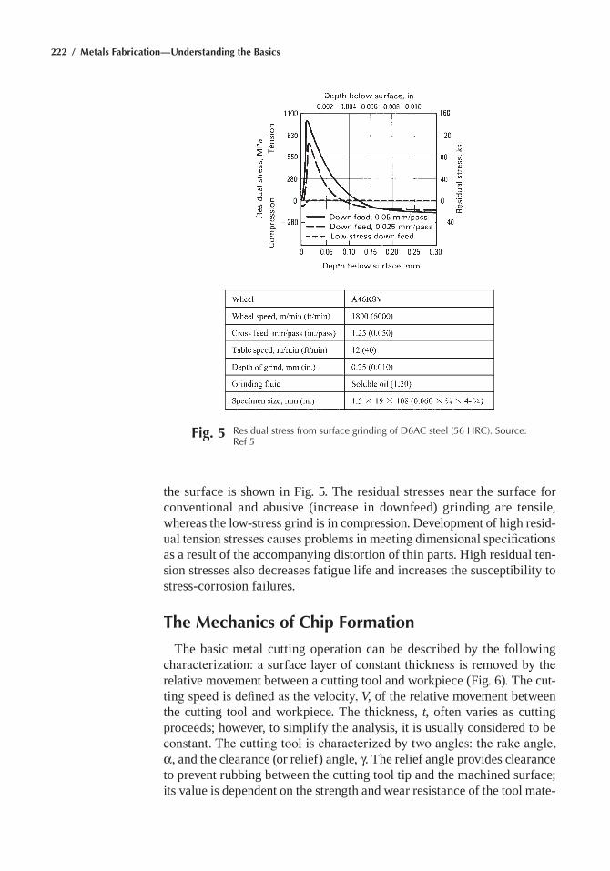
222 / Metals Fabrication—Understanding the Basics
the surface is shown in Fig. 5. The residual stresses near the surface for conventional and abusive (increase in downfeed) grinding are tensile, whereas the low-stress grind is in compression. Development of high resid-ual tension stresses causes problems in meeting dimensional specifications as a result of the accompanying distortion of thin parts. high residual ten-sion stresses also decreases fatigue life and increases the susceptibility to stress-corrosion failures.
The Mechanics of Chip Formation
The basic metal cutting operation can be described by the following characterization: a surface layer of constant thickness is removed by the relative movement between a cutting tool and workpiece (Fig. 6). The cut-ting speed is defined as the velocity, V, of the relative movement between the cutting tool and workpiece. The thickness, t, often varies as cutting proceeds; however, to simplify the analysis, it is usually considered to be constant. The cutting tool is characterized by two angles: the rake angle, α, and the clearance (or relief) angle, γ. The relief angle provides clearance to prevent rubbing between the cutting tool tip and the machined surface; its value is dependent on the strength and wear resistance of the tool mate-
Fig. 5 residual stress from surface grinding of D6aC steel (56 hrC). Source: ref 5
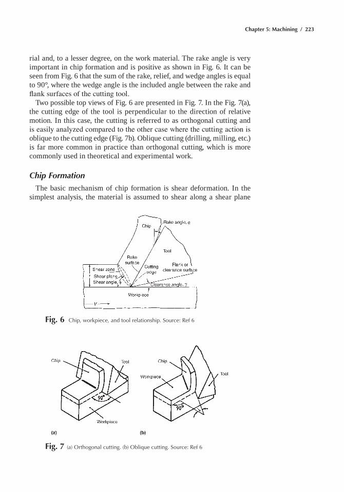
Chapter 5: Machining / 223
rial and, to a lesser degree, on the work material. The rake angle is very important in chip formation and is positive as shown in Fig. 6. it can be seen from Fig. 6 that the sum of the rake, relief, and wedge angles is equal to 90°, where the wedge angle is the included angle between the rake and flank surfaces of the cutting tool.
Two possible top views of Fig. 6 are presented in Fig. 7. in the Fig. 7(a), the cutting edge of the tool is perpendicular to the direction of relative motion. in this case, the cutting is referred to as orthogonal cutting and is easily analyzed compared to the other case where the cutting action is oblique to the cutting edge (Fig. 7b). oblique cutting (drilling, milling, etc.) is far more common in practice than orthogonal cutting, which is more commonly used in theoretical and experimental work.
Chip Formation
The basic mechanism of chip formation is shear deformation. in the simplest analysis, the material is assumed to shear along a shear plane
Fig. 6 Chip, workpiece, and tool relationship. Source: ref 6
Fig. 7 (a) Orthogonal cutting. (b) Oblique cutting. Source: ref 6
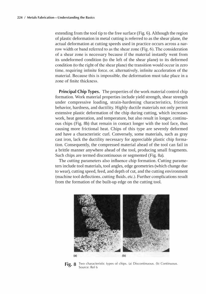
224 / Metals Fabrication—Understanding the Basics
extending from the tool tip to the free surface (Fig. 6). although the region of plastic deformation in metal cutting is referred to as the shear plane, the actual deformation at cutting speeds used in practice occurs across a nar-row width or band referred to as the shear zone (Fig. 6). The consideration of a shear zone is necessary because if the material instantly went from its undeformed condition (to the left of the shear plane) to its deformed condition (to the right of the shear plane) the transition would occur in zero time, requiring infinite force, or, alternatively, infinite acceleration of the material. Because this is impossible, the deformation must take place in a zone of finite thickness.
Principal Chip Types. The properties of the work material control chip formation. Work material properties include yield strength, shear strength under compressive loading, strain-hardening characteristics, friction behavior, hardness, and ductility. highly ductile materials not only permit extensive plastic deformation of the chip during cutting, which increases work, heat generation, and temperature, but also result in longer, continu-ous chips (Fig. 8b) that remain in contact longer with the tool face, thus causing more frictional heat. chips of this type are severely deformed and have a characteristic curl. conversely, some materials, such as gray cast iron, lack the ductility necessary for appreciable plastic chip forma-tion. consequently, the compressed material ahead of the tool can fail in a brittle manner anywhere ahead of the tool, producing small fragments. such chips are termed discontinuous or segmented (Fig. 8a).
The cutting parameters also influence chip formation. Cutting parame-ters include tool materials, tool angles, edge geometries (which change due to wear), cutting speed, feed, and depth of cut, and the cutting environment (machine tool deflections, cutting fluids, etc.). Further complications result from the formation of the built-up edge on the cutting tool.
Fig. 8 two characteristic types of chips. (a) Discontinuous. (b) Continuous. Source: ref 6
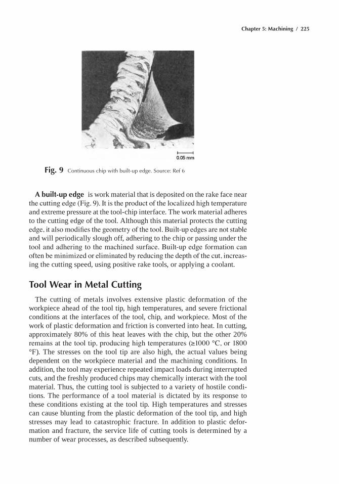
Chapter 5: Machining / 225
A built-up edge is work material that is deposited on the rake face near the cutting edge (Fig. 9). It is the product of the localized high temperature and extreme pressure at the tool-chip interface. The work material adheres to the cutting edge of the tool. although this material protects the cutting edge, it also modifies the geometry of the tool. Built-up edges are not stable and will periodically slough off, adhering to the chip or passing under the tool and adhering to the machined surface. Built-up edge formation can often be minimized or eliminated by reducing the depth of the cut, increas-ing the cutting speed, using positive rake tools, or applying a coolant.
Tool Wear in Metal Cutting
The cutting of metals involves extensive plastic deformation of the workpiece ahead of the tool tip, high temperatures, and severe frictional conditions at the interfaces of the tool, chip, and workpiece. Most of the work of plastic deformation and friction is converted into heat. in cutting, approximately 80% of this heat leaves with the chip, but the other 20% remains at the tool tip, producing high temperatures (≥1000 °C, or 1800 °F). The stresses on the tool tip are also high, the actual values being dependent on the workpiece material and the machining conditions. in addition, the tool may experience repeated impact loads during interrupted cuts, and the freshly produced chips may chemically interact with the tool material. Thus, the cutting tool is subjected to a variety of hostile condi-tions. The performance of a tool material is dictated by its response to these conditions existing at the tool tip. high temperatures and stresses can cause blunting from the plastic deformation of the tool tip, and high stresses may lead to catastrophic fracture. in addition to plastic defor-mation and fracture, the service life of cutting tools is determined by a number of wear processes, as described subsequently.
Fig. 9 Continuous chip with built-up edge. Source: ref 6
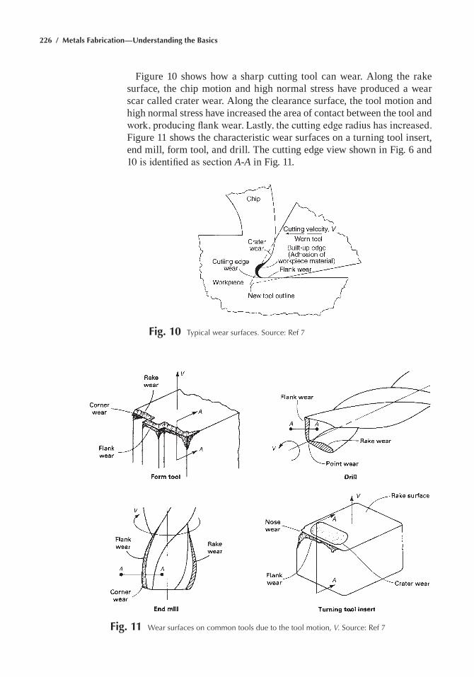
226 / Metals Fabrication—Understanding the Basics
Figure 10 shows how a sharp cutting tool can wear. along the rake surface, the chip motion and high normal stress have produced a wear scar called crater wear. along the clearance surface, the tool motion and high normal stress have increased the area of contact between the tool and work, producing flank wear. Lastly, the cutting edge radius has increased. Figure 11 shows the characteristic wear surfaces on a turning tool insert, end mill, form tool, and drill. The cutting edge view shown in Fig. 6 and 10 is identified as section A-A in Fig. 11.
Fig. 10 typical wear surfaces. Source: ref 7
Fig. 11 Wear surfaces on common tools due to the tool motion, V. Source: ref 7
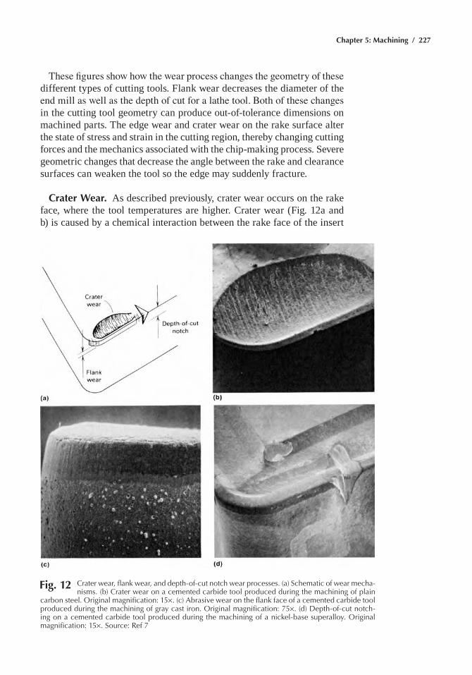
Chapter 5: Machining / 227
These figures show how the wear process changes the geometry of these different types of cutting tools. Flank wear decreases the diameter of the end mill as well as the depth of cut for a lathe tool. Both of these changes in the cutting tool geometry can produce out-of-tolerance dimensions on machined parts. The edge wear and crater wear on the rake surface alter the state of stress and strain in the cutting region, thereby changing cutting forces and the mechanics associated with the chip-making process. severe geometric changes that decrease the angle between the rake and clearance surfaces can weaken the tool so the edge may suddenly fracture.
Crater Wear. as described previously, crater wear occurs on the rake face, where the tool temperatures are higher. crater wear (Fig. 12a and b) is caused by a chemical interaction between the rake face of the insert
Fig. 12 Crater wear, flank wear, and depth-of-cut notch wear processes. (a) Schematic of wear mecha-nisms. (b) Crater wear on a cemented carbide tool produced during the machining of plain
carbon steel. Original magnification: 15¥. (c) abrasive wear on the flank face of a cemented carbide tool produced during the machining of gray cast iron. Original magnification: 75¥. (d) Depth-of-cut notch-ing on a cemented carbide tool produced during the machining of a nickel-base superalloy. Original magnification: 15¥. Source: ref 7
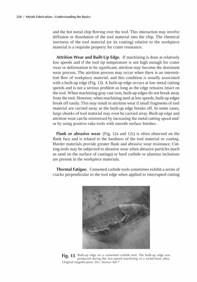
228 / Metals Fabrication—Understanding the Basics
and the hot metal chip flowing over the tool. This interaction may involve diffusion or dissolution of the tool material into the chip. The chemical inertness of the tool material (or its coating) relative to the workpiece material is a requisite property for crater resistance.
Attrition Wear and Built-Up Edge. if machining is done at relatively low speeds and if the tool tip temperature is not high enough for crater wear or deformation to be significant, attrition may become the dominant wear process. The attrition process may occur when there is an intermit-tent flow of workpiece material, and this condition is usually associated with a built-up edge (Fig. 13). a built-up edge occurs at low metal cutting speeds and is not a serious problem as long as the edge remains intact on the tool. When machining gray cast iron, built-up edges do not break away from the tool. however, when machining steel at low speeds, built-up edges break off easily. This may result in attrition wear if small fragments of tool material are carried away as the built-up edge breaks off. in some cases, large chunks of tool material may even be carried away. Built-up edge and attrition wear can be minimized by increasing the metal cutting speed and/or by using positive-rake tools with smooth surface finishes.
Flank or abrasive wear (Fig. 12a and 12c) is often observed on the flank face and is related to the hardness of the tool material or coating. Harder materials provide greater flank and abrasive wear resistance. Cut-ting tools may be subjected to abrasive wear when abrasive particles (such as sand on the surface of castings) or hard carbide or alumina inclusions are present in the workpiece materials.
Thermal Fatigue. cemented carbide tools sometimes exhibit a series of cracks perpendicular to the tool edge when applied to interrupted cutting
Fig. 13 Built-up edge on a cemented carbide tool. the built-up edge was produced during the low-speed machining of a nickel-base alloy.
Original magnification: 20¥. Source: ref 7
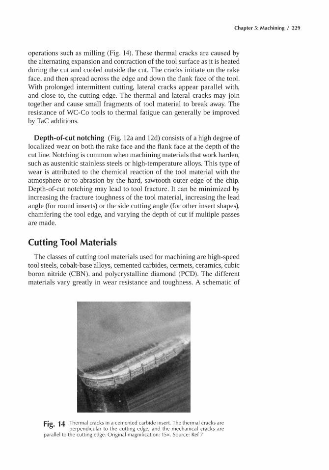
Chapter 5: Machining / 229
operations such as milling (Fig. 14). These thermal cracks are caused by the alternating expansion and contraction of the tool surface as it is heated during the cut and cooled outside the cut. The cracks initiate on the rake face, and then spread across the edge and down the flank face of the tool. With prolonged intermittent cutting, lateral cracks appear parallel with, and close to, the cutting edge. The thermal and lateral cracks may join together and cause small fragments of tool material to break away. The resistance of Wc-co tools to thermal fatigue can generally be improved by Tac additions.
Depth-of-cut notching (Fig. 12a and 12d) consists of a high degree of localized wear on both the rake face and the flank face at the depth of the cut line. notching is common when machining materials that work harden, such as austenitic stainless steels or high-temperature alloys. This type of wear is attributed to the chemical reaction of the tool material with the atmosphere or to abrasion by the hard, sawtooth outer edge of the chip. Depth-of-cut notching may lead to tool fracture. It can be minimized by increasing the fracture toughness of the tool material, increasing the lead angle (for round inserts) or the side cutting angle (for other insert shapes), chamfering the tool edge, and varying the depth of cut if multiple passes are made.
Cutting Tool Materials
The classes of cutting tool materials used for machining are high-speed tool steels, cobalt-base alloys, cemented carbides, cermets, ceramics, cubic boron nitride (CBN), and polycrystalline diamond (PCD). The different materials vary greatly in wear resistance and toughness. a schematic of
Fig. 14 thermal cracks in a cemented carbide insert. the thermal cracks are perpendicular to the cutting edge, and the mechanical cracks are
parallel to the cutting edge. Original magnification: 15¥. Source: ref 7
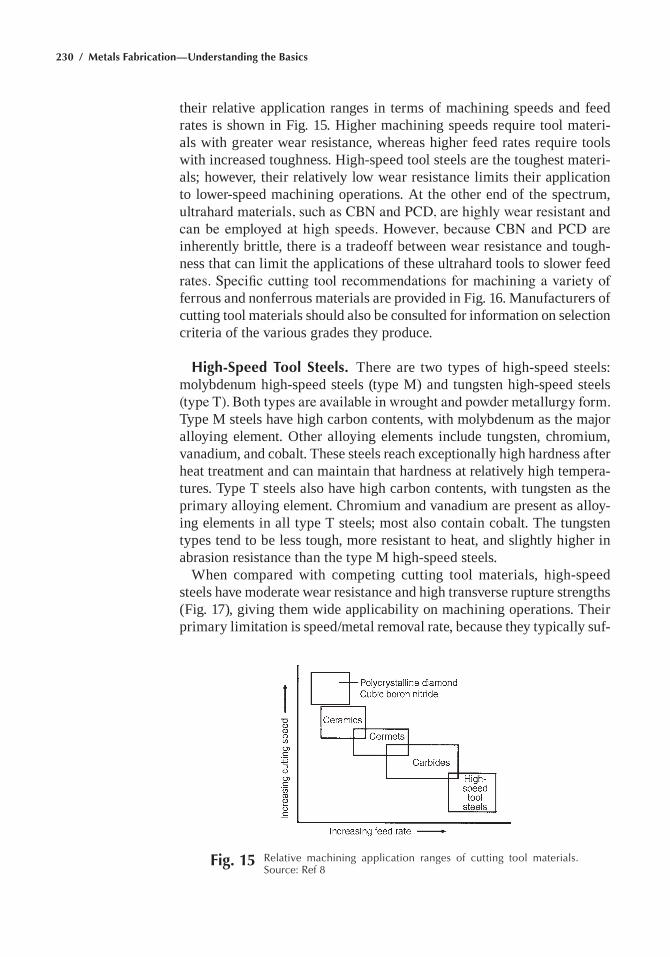
230 / Metals Fabrication—Understanding the Basics
their relative application ranges in terms of machining speeds and feed rates is shown in Fig. 15. higher machining speeds require tool materi-als with greater wear resistance, whereas higher feed rates require tools with increased toughness. high-speed tool steels are the toughest materi-als; however, their relatively low wear resistance limits their application to lower-speed machining operations. at the other end of the spectrum, ultrahard materials, such as CBN and PCD, are highly wear resistant and can be employed at high speeds. However, because CBN and PCD are inherently brittle, there is a tradeoff between wear resistance and tough-ness that can limit the applications of these ultrahard tools to slower feed rates. Specific cutting tool recommendations for machining a variety of ferrous and nonferrous materials are provided in Fig. 16. Manufacturers of cutting tool materials should also be consulted for information on selection criteria of the various grades they produce.
High-Speed Tool Steels. There are two types of high-speed steels: molybdenum high-speed steels (type M) and tungsten high-speed steels (type T). Both types are available in wrought and powder metallurgy form. Type M steels have high carbon contents, with molybdenum as the major alloying element. other alloying elements include tungsten, chromium, vanadium, and cobalt. These steels reach exceptionally high hardness after heat treatment and can maintain that hardness at relatively high tempera-tures. Type T steels also have high carbon contents, with tungsten as the primary alloying element. chromium and vanadium are present as alloy-ing elements in all type T steels; most also contain cobalt. The tungsten types tend to be less tough, more resistant to heat, and slightly higher in abrasion resistance than the type M high-speed steels.
When compared with competing cutting tool materials, high-speed steels have moderate wear resistance and high transverse rupture strengths (Fig. 17), giving them wide applicability on machining operations. Their primary limitation is speed/metal removal rate, because they typically suf-
Fig. 15 relative machining application ranges of cutting tool materials. Source: ref 8
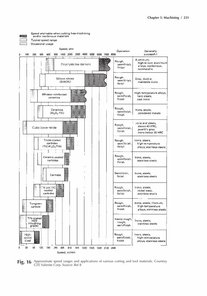
Chapter 5: Machining / 231
Fig. 16 approximate speed ranges and applications of various cutting and tool materials. Courtesy Gte Valenite Corp. Source: ref 8
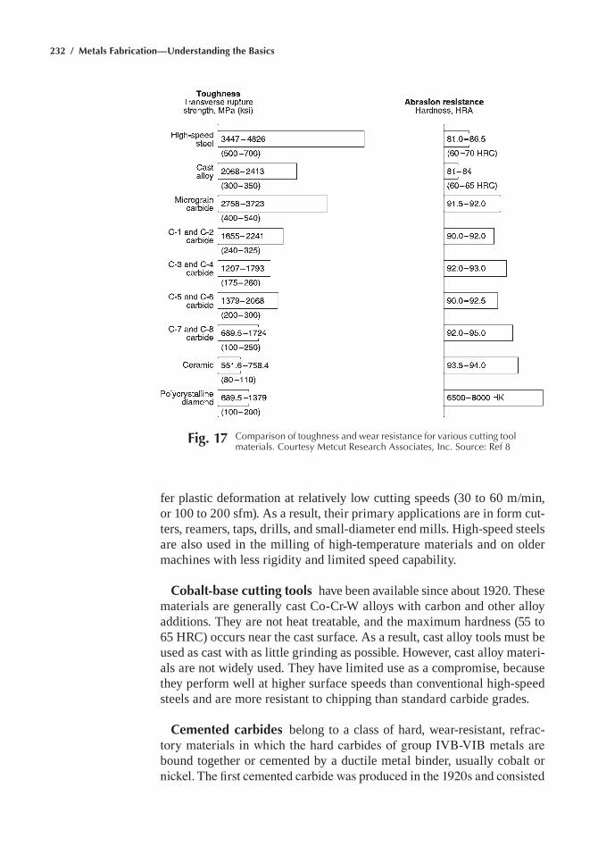
232 / Metals Fabrication—Understanding the Basics
fer plastic deformation at relatively low cutting speeds (30 to 60 m/min, or 100 to 200 sfm). as a result, their primary applications are in form cut-ters, reamers, taps, drills, and small-diameter end mills. high-speed steels are also used in the milling of high-temperature materials and on older machines with less rigidity and limited speed capability.
Cobalt-base cutting tools have been available since about 1920. These materials are generally cast co-cr-W alloys with carbon and other alloy additions. They are not heat treatable, and the maximum hardness (55 to 65 hrc) occurs near the cast surface. as a result, cast alloy tools must be used as cast with as little grinding as possible. however, cast alloy materi-als are not widely used. They have limited use as a compromise, because they perform well at higher surface speeds than conventional high-speed steels and are more resistant to chipping than standard carbide grades.
Cemented carbides belong to a class of hard, wear-resistant, refrac-tory materials in which the hard carbides of group IVB-VIB metals are bound together or cemented by a ductile metal binder, usually cobalt or nickel. The first cemented carbide was produced in the 1920s and consisted
Fig. 17 Comparison of toughness and wear resistance for various cutting tool materials. Courtesy Metcut research associates, Inc. Source: ref 8
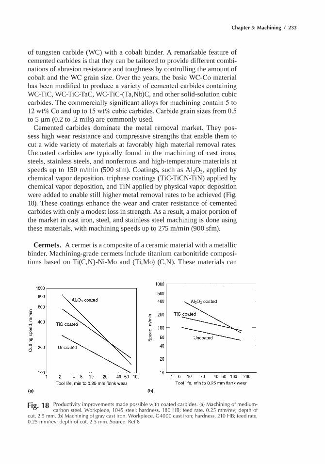
Chapter 5: Machining / 233
of tungsten carbide (Wc) with a cobalt binder. a remarkable feature of cemented carbides is that they can be tailored to provide different combi-nations of abrasion resistance and toughness by controlling the amount of cobalt and the WC grain size. Over the years, the basic WC-Co material has been modified to produce a variety of cemented carbides containing Wc-Tic, Wc-Tic-Tac, Wc-Tic-(Ta,nb)c, and other solid-solution cubic carbides. The commercially significant alloys for machining contain 5 to 12 wt% Co and up to 15 wt% cubic carbides. Carbide grain sizes from 0.5 to 5 mm (0.2 to .2 mils) are commonly used.
cemented carbides dominate the metal removal market. They pos-sess high wear resistance and compressive strengths that enable them to cut a wide variety of materials at favorably high material removal rates. Uncoated carbides are typically found in the machining of cast irons, steels, stainless steels, and nonferrous and high-temperature materials at speeds up to 150 m/min (500 sfm). coatings, such as al2o3, applied by chemical vapor deposition, triphase coatings (Tic-Ticn-Tin) applied by chemical vapor deposition, and Tin applied by physical vapor deposition were added to enable still higher metal removal rates to be achieved (Fig. 18). These coatings enhance the wear and crater resistance of cemented carbides with only a modest loss in strength. as a result, a major portion of the market in cast iron, steel, and stainless steel machining is done using these materials, with machining speeds up to 275 m/min (900 sfm).
Cermets. a cermet is a composite of a ceramic material with a metallic binder. Machining-grade cermets include titanium carbonitride composi-tions based on Ti(c,n)-ni-Mo and (Ti,Mo) (c,n). These materials can
Fig. 18 productivity improvements made possible with coated carbides. (a) Machining of medium-carbon steel. Workpiece, 1045 steel; hardness, 180 hB; feed rate, 0.25 mm/rev; depth of
cut, 2.5 mm. (b) Machining of gray cast iron. Workpiece, G4000 cast iron; hardness, 210 hB; feed rate, 0.25 mm/rev; depth of cut, 2.5 mm. Source: ref 8
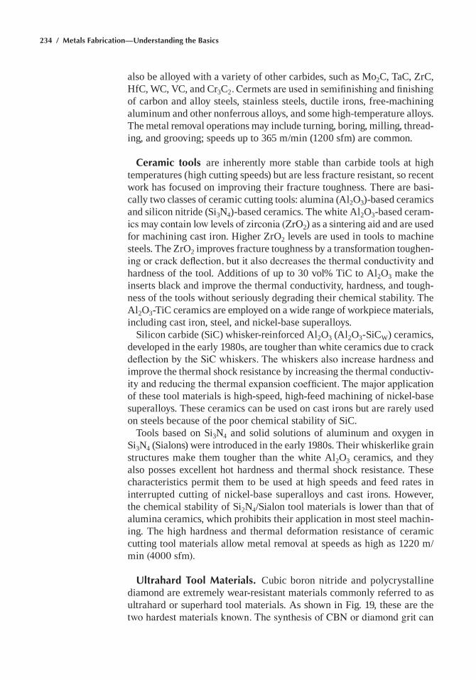
234 / Metals Fabrication—Understanding the Basics
also be alloyed with a variety of other carbides, such as Mo2c, Tac, Zrc, hfc, Wc, vc, and cr3c2. Cermets are used in semifinishing and finishing of carbon and alloy steels, stainless steels, ductile irons, free-machining aluminum and other nonferrous alloys, and some high-temperature alloys. The metal removal operations may include turning, boring, milling, thread-ing, and grooving; speeds up to 365 m/min (1200 sfm) are common.
Ceramic tools are inherently more stable than carbide tools at high temperatures (high cutting speeds) but are less fracture resistant, so recent work has focused on improving their fracture toughness. There are basi-cally two classes of ceramic cutting tools: alumina (al2o3)-based ceramics and silicon nitride (si3n4)-based ceramics. The white al2o3-based ceram-ics may contain low levels of zirconia (ZrO2) as a sintering aid and are used for machining cast iron. higher Zro2 levels are used in tools to machine steels. The Zro2 improves fracture toughness by a transformation toughen-ing or crack deflection, but it also decreases the thermal conductivity and hardness of the tool. additions of up to 30 vol% Tic to al2o3 make the inserts black and improve the thermal conductivity, hardness, and tough-ness of the tools without seriously degrading their chemical stability. The al2o3-Tic ceramics are employed on a wide range of workpiece materials, including cast iron, steel, and nickel-base superalloys.
silicon carbide (sic) whisker-reinforced al2o3 (al2o3-sicW) ceramics, developed in the early 1980s, are tougher than white ceramics due to crack deflection by the SiC whiskers. The whiskers also increase hardness and improve the thermal shock resistance by increasing the thermal conductiv-ity and reducing the thermal expansion coefficient. The major application of these tool materials is high-speed, high-feed machining of nickel-base superalloys. These ceramics can be used on cast irons but are rarely used on steels because of the poor chemical stability of sic.
Tools based on si3n4 and solid solutions of aluminum and oxygen in si3n4 (sialons) were introduced in the early 1980s. Their whiskerlike grain structures make them tougher than the white al2o3 ceramics, and they also posses excellent hot hardness and thermal shock resistance. These characteristics permit them to be used at high speeds and feed rates in interrupted cutting of nickel-base superalloys and cast irons. however, the chemical stability of si2n4/sialon tool materials is lower than that of alumina ceramics, which prohibits their application in most steel machin-ing. The high hardness and thermal deformation resistance of ceramic cutting tool materials allow metal removal at speeds as high as 1220 m/min (4000 sfm).
Ultrahard Tool Materials. cubic boron nitride and polycrystalline diamond are extremely wear-resistant materials commonly referred to as ultrahard or superhard tool materials. as shown in Fig. 19, these are the two hardest materials known. The synthesis of CBN or diamond grit can

Chapter 5: Machining / 235
be achieved by static high-pressure, high-temperature (hPhT) process-ing or by dynamic (explosive) techniques. in addition, diamond is also synthesized under metastable low-pressure conditions by chemical vapor deposition.
Cubic boron nitride, which has a hardness of 4700 HK, is the material of choice for machining steels with hardnesses exceeding 50 hrc. other applications include machining of cast irons (typically 180 to 240 HB) and superalloys (>35 HRC). Conversely, PCD (7000 HK) cannot be used for steel machining because of its solubility and the catalytic effect of iron, which causes graphitization of the diamond. The primary application of PcD tools is in the very high-speed machining of aluminum-silicon alloys, composites, and other nonmetallic workpieces. speeds as high as 2000 m/min (6500 sfm) can be achieved during machining of aluminum-silicon alloys with PcD tooling.
Application/Grade Selection
Knowledge of the machinability characteristics of the workpiece mate-rial and the properties of the cutting tool material is the starting point for selecting a grade-geometry combination for any machining operation. The task of the tooling engineer is to select, from the vast numbers of possibilities, the grade that will give the best performance, predictability, reliability, and cost. Table 4 gives general guidelines for depth of cut, feed rate, and cutting speed for finish turning of selected workpiece materials with competing cutting tool materials.
Fig. 19 typical hardness values of hard/abrasive materials and some work materials. Source: ref 8
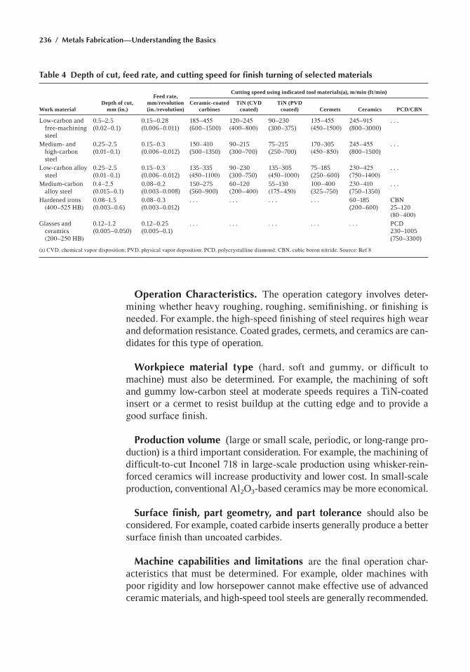
236 / Metals Fabrication—Understanding the Basics
Operation Characteristics. The operation category involves deter-mining whether heavy roughing, roughing, semifinishing, or finishing is needed. For example, the high-speed finishing of steel requires high wear and deformation resistance. coated grades, cermets, and ceramics are can-didates for this type of operation.
Workpiece material type (hard, soft and gummy, or difficult to machine) must also be determined. For example, the machining of soft and gummy low-carbon steel at moderate speeds requires a Tin-coated insert or a cermet to resist buildup at the cutting edge and to provide a good surface finish.
Production volume (large or small scale, periodic, or long-range pro-duction) is a third important consideration. For example, the machining of difficult-to-cut Inconel 718 in large-scale production using whisker-rein-forced ceramics will increase productivity and lower cost. in small-scale production, conventional al2o3-based ceramics may be more economical.
Surface finish, part geometry, and part tolerance should also be considered. For example, coated carbide inserts generally produce a better surface finish than uncoated carbides.
Machine capabilities and limitations are the final operation char-acteristics that must be determined. For example, older machines with poor rigidity and low horsepower cannot make effective use of advanced ceramic materials, and high-speed tool steels are generally recommended.
Table 4 Depth of cut, feed rate, and cutting speed for finish turning of selected materials
Work materialDepth of cut,
mm (in.)
Feed rate, mm/revolution (in./revolution)
Cutting speed using indicated tool materials(a), m/min (ft/min)
Ceramic-coated carbines
TiN (CVD coated)
TiN (PVD coated) Cermets Ceramics PCD/CBN
Low-carbon and free-machining steel
0.5–2.5 (0.02–0.1)
0.15–0.28 (0.006–0.011)
185–455 (600–1500)
120–245 (400–800)
90–230 (300–375)
135–455 (450–1500)
245–915 (800–3000)
. . .
Medium- and high-carbon steel
0.25–2.5 (0.01–0.1)
0.15–0.3 (0.006–0.012)
150–410 (500–1350)
90–215 (300–700)
75–215 (250–700)
170–305 (450–850)
245–455 (800–1500)
. . .
Low-carbon alloy steel
0.25–2.5 (0.01–0.1)
0.15–0.3 (0.006–0.012)
135–335 (450–1100)
90–230 (300–750)
135–305 (450–1000)
75–185 (250–600)
230–425 (750–1400)
. . .
Medium-carbon alloy steel
0.4–2.5 (0.015–0.1)
0.08–0.2 (0.003–0.008)
150–275 (560–900)
60–120 (200–400)
55–130 (175–450)
100–400 (325–750)
230–410 (750–1350)
. . .
hardened irons (400–525 HB)
0.08–1.5 (0.003–0.6)
0.08–0.3 (0.003–0.012)
. . . . . . . . . . . . 60–185 (200–600)
CBN 25–120 (80–400)
glasses and ceramics (200–250 HB)
0.12–1.2 (0.005–0.050)
0.12–0.25 (0.005–0.1)
. . . . . . . . . . . . . . . PcD 230–1005 (750–3300)
(a) CVD, chemical vapor disposition; PVD, physical vapor deposition; PCD, polycrystalline diamond; CBN, cubic boron nitride. Source: Ref 8
Chapter 5: Machining / 237
Cutting Fluids
When properly applied, cutting fluids can increase productivity and reduce costs by making possible the use of higher cutting speeds, higher feed rates, and greater depths of cut. The effective application of cutting fluids can also lengthen tool life, decrease surface roughness, increase dimensional accuracy, and decrease the amount of power that is consumed when cutting dry. Knowledge of cutting fluid functions, types, physical limitations, and compositions plays an important role in the selection and application of the proper fluid for a specific machining situation.
Depending on the machining operation being performed, a cutting fluid has one or more of the following functions:
• cooling the tool, workpiece, and chip• Lubricating (reducing friction and minimizing erosion on the tool)• controlling the built-up edge on the tool• Flushing away chips• Protecting the workpiece from corrosion
The relative importance of each function depends on the work material, the cutting tool, the cutting conditions, and the finish required on the part.
Types of Cutting and Grinding Fluids
Many cutting fluids are available today to satisfy the requirements of modern machine tools. Although there is no all-purpose cutting fluid, some fluids offer considerable versatility while others are tailored for specific applications. For economic reasons, most metalworking firms try to use as few different fluids as possible. Preferred fluids have long life and do not require constant changing or modifying.
Each of the basic types of fluids has distinctive features, advantages, and limitations, although the dividing line is not always clearly identifiable. The four basic types of cutting fluids are:
• Cutting oils: straight and compounded mineral oil (plus additives)• Water-miscible (water-soluble) fluids: emulsifiable oils (soluble oils),
chemical (synthetic) fluids, and semichemical (semisynthetic) fluids• Gases• Paste and solid lubricants
The cutting oils and the water-miscible fluids are the types most commonly used. Cooling is best accomplished by water-miscible fluids, while oil-base fluids provide better lubrication.
238 / Metals Fabrication—Understanding the Basics
Selection of a Cutting Fluid
The proper choice of a cutting fluid depends on many complex inter-related factors. of primary concern are machinability (or grindability) of the material, compatibility (metallurgical, chemical, and human), and acceptability (fluid properties, reliability, and stability). The selection of the type of cutting fluid should be based on the type of machining opera-tion, the material being machined, the tool material, and the machining conditions—cutting speed, feed, and depth of cut.
One of the most important factors in selecting a cutting fluid is the nature of the cutting operation itself. The various machining processes naturally differ in metal removal characteristics. The more difficult operations will place greater demands on a cutting fluid. Therefore, selection is a matter of assessing the severity of the machining operation and selecting the appro-priate cutting fluid. The approximate ratings for the machining processes, in order of decreasing severity, are:
1. internal broaching2. external broaching3. Tapping4. Threading5. gear cutting6. Deep hole drilling7. Boring8. screw machining with form tools9. high-speed, light-feed screw machining
10. reaming11. Milling12. Drilling13. Planing and shaping14. Turning, single-point tools15. sawing16. grinding
These ratings cannot be regarded as absolute, because variations in the tool geometry and workpiece material will change the severity of the machin-ing operation.
For heavy-duty machining operations (such as tapping or broaching), medium- or heavy-duty cutting oils are generally used. Horizontal broach-ing of steel usually requires a heavier bodied or more chemically active oil than vertical surface broaching under comparable conditions. The heavier oil clings to the horizontal broach better than a water-miscible fluid, and chemical activity aids in efficient cutting. For vertical surface broaching of mild steels, emulsions or solutions can be used, but the usual choice is an oil.
Chapter 5: Machining / 239
cutting oils can be ranked in order of increasing load-carrying capacity as:
1. straight mineral oil2. Mineral oil with fatty additives3. Mineral oil with chlorinated additives4. Mineral oil with sulfurized fatty additives5. Mineral oil with free sulfur and sulfurized or chlorinated compounds
Low-speed operations require the lubricating properties of cutting oils. as a general rule, cutting oils should be used at cutting speeds below 30 m/min (100 ft/min). cutting oils with extreme pressure (eP) lubricants are effective in a wide variety of machining operations on many materials up to speeds of 60 m/min (200 ft/min). at speeds of approximately 60 m/min (200 ft/min), chemical action is much less effective than at the lower speeds. chemical action diminishes quickly and becomes virtually nil as the cutting speed is increased to 120 m/min (400 ft/min).
Both tapping and threading involve many small cutting edges in continu-ous contact with the work throughout the cut. The design of the tools and the nature of these operations shield the edges of the tools from the flow and the cooling effect of the cutting fluid, particularly in tapping.
Drilling can be a difficult operation when done on difficult-to-machine materials. Drilling speeds are generally slower than those used for other operations because the cutting edge is in continuous contact with the metal when cutting and the cutting edges are shielded from the flow and cooling action of the cutting fluid. The preferred fluids for conventional drilling operations are emulsifiable oils and sulfurized or chlorinated mineral oils. These fluids provide some lubricity to prevent chatter and friction-generated heat while carrying away the heat generated by chip formation. oil-hole drills should be used wherever possible. There are some opera-tions for which oils are specially formulated. For example, honing requires the use of a thinner, paraffinic-based oil.
For many high-speed operations, such as grinding and turning or mill-ing with carbides, the most important benefit is provided by the superior cooling characteristics of the water-miscible fluids. In such instances, lubrication and anti-weld properties are less important. at high speeds, time for reaction between fluid additives and the workpiece is reduced to a minimum. Further, the higher relative velocities of the work and the tool virtually preclude the fluid from reaching the work zone. Consequently, gross cooling is required to prevent catastrophic tool failure from crater wear, to prevent distortion in the workpiece from heat buildup, and to control workpiece size.
Some emulsifiable oils and chemical fluids are formulated specifically for grinding operations and are used in concentrations of 1 part concen-
240 / Metals Fabrication—Understanding the Basics
trate in 25 to 60 parts water. An increase in the richness of emulsifiable oil mixtures from 2.5 to 10% can improve the grinding ratio and the work-piece finish and reduce horsepower requirements. Note that the grinding ratio is a measure of the volume of material removed per unit volume of wheel wear.
severe grinding operations, such as form, thread, and plunge grinding where wheel form is a critical factor, require the use of cutting oils or eP-compounded emulsifiable oils. It should be noted that for the low-stress grinding technique, the use of an oil-base fluid results in less surface dis-tortion. grinding oils reduce friction, thus reducing the heat generated. They permit heavier cuts to be taken, produce smoother finishes, reduce wheel breakdown, and, hence, allow better form control. oils suffer from the disadvantages of allowing heat buildup in the workpiece, tending to hold chips in suspension, and smoking or burning. The messiness of oil vapors is also a nuisance.
In summary, from a machinability viewpoint, cutting and grinding fluids should be selected to provide the following:
Greater lubrication
• at relatively low speeds• On the more difficult-to-machine materials• For more difficult operations• For better surface finish
Greater cooling
• at relatively high speeds• on the easier-to-machine materials• For easier operations• Where heat buildup in the part is a problem
a number of other important factors must be considered when select-ing cutting and grinding fluids. These include compatibility of the fluid with the material being machined, the quality of the water in which it is mixed, tramp oil contamination, and the machine tool. The acceptabil-ity of the fluid, in terms of its properties, reliability, and stability, is also important. Other factors to be considered include the quantity of fluid used and the method of application, facilities for storing, handling, cleaning, or recycling the fluid, the quality of water used in the aqueous emulsions or solutions, and the rust and rancidity control necessary. economic consid-erations include any waste treatment facilities that may be required prior to disposal. The effect of the cutting fluid on the total machining cost per piece must be considered because the more expensive fluids can sometimes be more economical in the long run.
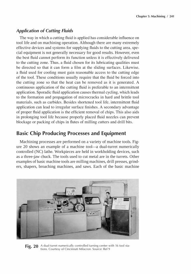
Chapter 5: Machining / 241
Application of Cutting Fluids
The way in which a cutting fluid is applied has considerable influence on tool life and on machining operation. although there are many extremely effective devices and systems for supplying fluids to the cutting area, spe-cial equipment is not generally necessary for good results. however, even the best fluid cannot perform its function unless it is effectively delivered to the cutting zone. Thus, a fluid chosen for its lubricating qualities must be directed so that it can form a film at the sliding surfaces. Likewise, a fluid used for cooling must gain reasonable access to the cutting edge of the tool. These conditions usually require that the fluid be forced into the cutting zone so that the heat can be removed as it is generated. A continuous application of the cutting fluid is preferable to an intermittent application. Sporadic fluid application causes thermal cycling, which leads to the formation and propagation of microcracks in hard and brittle tool materials, such as carbides. Besides shortened tool life, intermittent fluid application can lead to irregular surface finishes. A secondary advantage of proper fluid application is the efficient removal of chips. This also aids in prolonging tool life because properly placed fluid nozzles can prevent blockage or packing of chips in flutes of milling cutters and drill bits.
Basic Chip Producing Processes and Equipment
Machining processes are performed on a variety of machine tools. Fig-ure 20 shows an example of a machine tool—a dual-turret numerically controlled (nc) lathe. Workpieces are held in workholding devices, such as a three-jaw chuck. The tools used to cut metal are in the turrets. other examples of basic machine tools are milling machines, drill presses, grind-ers, shapers, broaching machines, and saws. each of the basic machine
Fig. 20 a dual-turret numerically controlled turning center with 16 tool sta-tions. Courtesy of Cincinnati Milacron. Source: ref 9
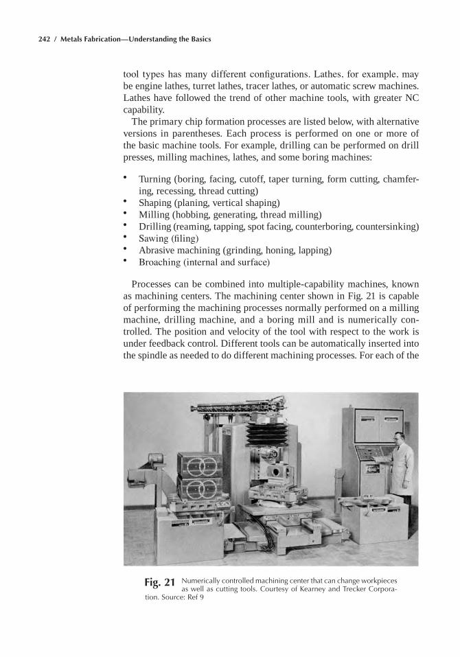
242 / Metals Fabrication—Understanding the Basics
tool types has many different configurations. Lathes, for example, may be engine lathes, turret lathes, tracer lathes, or automatic screw machines. Lathes have followed the trend of other machine tools, with greater nc capability.
The primary chip formation processes are listed below, with alternative versions in parentheses. each process is performed on one or more of the basic machine tools. For example, drilling can be performed on drill presses, milling machines, lathes, and some boring machines:
• Turning (boring, facing, cutoff, taper turning, form cutting, chamfer-ing, recessing, thread cutting)
• shaping (planing, vertical shaping)• Milling (hobbing, generating, thread milling)• Drilling (reaming, tapping, spot facing, counterboring, countersinking)• Sawing (filing)• abrasive machining (grinding, honing, lapping)• Broaching (internal and surface)
Processes can be combined into multiple-capability machines, known as machining centers. The machining center shown in Fig. 21 is capable of performing the machining processes normally performed on a milling machine, drilling machine, and a boring mill and is numerically con-trolled. The position and velocity of the tool with respect to the work is under feedback control. Different tools can be automatically inserted into the spindle as needed to do different machining processes. For each of the
Fig. 21 Numerically controlled machining center that can change workpieces as well as cutting tools. Courtesy of Kearney and trecker Corpora-
tion. Source: ref 9
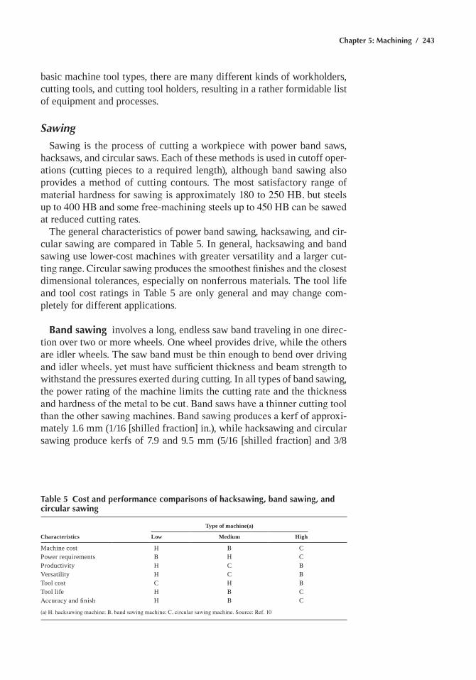
Chapter 5: Machining / 243
basic machine tool types, there are many different kinds of workholders, cutting tools, and cutting tool holders, resulting in a rather formidable list of equipment and processes.
Sawing
sawing is the process of cutting a workpiece with power band saws, hacksaws, and circular saws. each of these methods is used in cutoff oper-ations (cutting pieces to a required length), although band sawing also provides a method of cutting contours. The most satisfactory range of material hardness for sawing is approximately 180 to 250 HB, but steels up to 400 HB and some free-machining steels up to 450 HB can be sawed at reduced cutting rates.
The general characteristics of power band sawing, hacksawing, and cir-cular sawing are compared in Table 5. in general, hacksawing and band sawing use lower-cost machines with greater versatility and a larger cut-ting range. Circular sawing produces the smoothest finishes and the closest dimensional tolerances, especially on nonferrous materials. The tool life and tool cost ratings in Table 5 are only general and may change com-pletely for different applications.
Band sawing involves a long, endless saw band traveling in one direc-tion over two or more wheels. one wheel provides drive, while the others are idler wheels. The saw band must be thin enough to bend over driving and idler wheels, yet must have sufficient thickness and beam strength to withstand the pressures exerted during cutting. in all types of band sawing, the power rating of the machine limits the cutting rate and the thickness and hardness of the metal to be cut. Band saws have a thinner cutting tool than the other sawing machines. Band sawing produces a kerf of approxi-mately 1.6 mm (1/16 [shilled fraction] in.), while hacksawing and circular sawing produce kerfs of 7.9 and 9.5 mm (5/16 [shilled fraction] and 3/8
Table 5 Cost and performance comparisons of hacksawing, band sawing, and circular sawing
Characteristics
Type of machine(a)
Low Medium High
Machine cost h B cPower requirements B h cProductivity h c Bversatility h c BTool cost c h BTool life h B cAccuracy and finish h B c
(a) H. hacksawing machine; B, band sawing machine; C, circular sawing machine. Source: Ref. 10
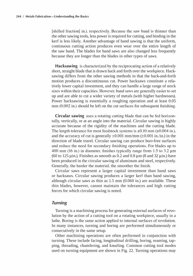
244 / Metals Fabrication—Understanding the Basics
[shilled fraction] in.), respectively. Because the saw band is thinner than the other sawing tools, less power is required for cutting, and binding in the kerf is less likely. another advantage of band sawing is that the uniform, continuous cutting action produces even wear over the entire length of the saw band. The blades for band saws are also changed less frequently because they are longer than the blades in other types of saws.
Hacksawing is characterized by the reciprocating action of a relatively short, straight blade that is drawn back and forth over the workpiece. hack-sawing differs from the other sawing methods in that the back-and-forth motion produces a discontinuous cut. Power hacksaws constitute a rela-tively lower capital investment, and they can handle a large range of stock sizes within their capacities. However, band saws are generally easier to set up and are able to cut a wider variety of metals (with higher hardnesses). Power hacksawing is essentially a roughing operation and at least 0.05 mm (0.002 in.) should be left on the cut surfaces for subsequent finishing.
Circular sawing uses a rotating cutting blade that can be fed horizon-tally, vertically, or at an angle into the material. circular sawing is highly accurate because of the rigidity of the machines and the cutting blade. The length tolerance for most feedstock systems is ±0.10 mm (±0.004 in.), and the accuracy of cut is generally ±0.001 mm/mm (±0.001 in./in.) in the direction of blade travel. circular sawing can produce burr-free surfaces and reduce the need for secondary finishing operations. For blades up to 400 mm (16 in.) in diameter, finishes typically range from 1.5 to 3.2 mm (60 to 125 min.). Finishes as smooth as 0.2 and 0.8 mm (8 and 32 min.) have been produced in the circular sawing of aluminum and steel, respectively. Generally, the harder the material, the smoother the finish.
circular saws represent a larger capital investment than band saws or hacksaws. circular sawing produces a larger kerf than band sawing, although circular saws as thin as 1.5 mm (0.060 in.) are available. These thin blades, however, cannot maintain the tolerances and high cutting forces for which circular sawing is noted.
Turning
Turning is a machining process for generating external surfaces of revo-lution by the action of a cutting tool on a rotating workpiece, usually in a lathe. Boring is the same action applied to internal surfaces of revolution. in many instances, turning and boring are performed simultaneously or consecutively in the same setup.
other machining operations are often performed in conjunction with turning. These include facing, longitudinal drilling, boring, reaming, tap-ping, threading, chamfering, and knurling. common cutting tool modes used on turning equipment are shown in Fig. 22. Turning operations may
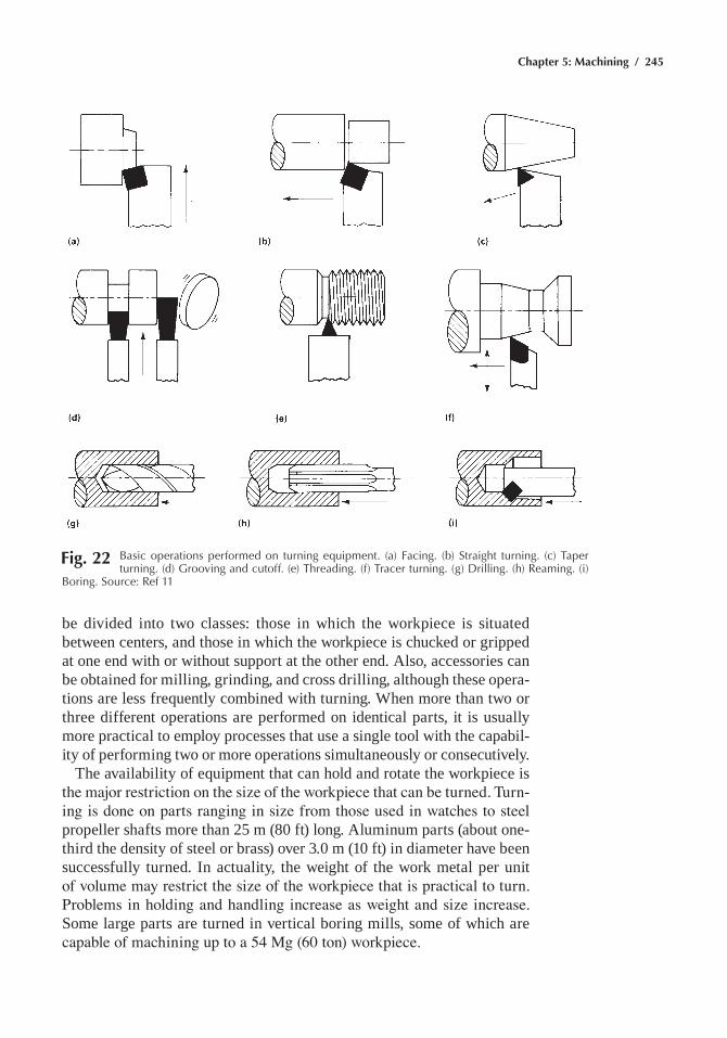
Chapter 5: Machining / 245
be divided into two classes: those in which the workpiece is situated between centers, and those in which the workpiece is chucked or gripped at one end with or without support at the other end. also, accessories can be obtained for milling, grinding, and cross drilling, although these opera-tions are less frequently combined with turning. When more than two or three different operations are performed on identical parts, it is usually more practical to employ processes that use a single tool with the capabil-ity of performing two or more operations simultaneously or consecutively.
The availability of equipment that can hold and rotate the workpiece is the major restriction on the size of the workpiece that can be turned. Turn-ing is done on parts ranging in size from those used in watches to steel propeller shafts more than 25 m (80 ft) long. aluminum parts (about one-third the density of steel or brass) over 3.0 m (10 ft) in diameter have been successfully turned. in actuality, the weight of the work metal per unit of volume may restrict the size of the workpiece that is practical to turn. Problems in holding and handling increase as weight and size increase. some large parts are turned in vertical boring mills, some of which are capable of machining up to a 54 Mg (60 ton) workpiece.
Fig. 22 Basic operations performed on turning equipment. (a) Facing. (b) Straight turning. (c) taper turning. (d) Grooving and cutoff. (e) threading. (f) tracer turning. (g) Drilling. (h) reaming. (i)
Boring. Source: ref 11
246 / Metals Fabrication—Understanding the Basics
capacities of lathes range from fractional horsepower to more than 150 kW (200 hp) for vertical boring mills. Power requirements differ greatly for the different families of alloys, averaging approximately 4.55 ¥ 10–6, 1.14 ¥ 10–5, and 3.64 ¥ 10–5 kW/mm3/min (0.1, 0.25, and 0.8 hp/in.3/min) for magnesium alloys, copper alloys, and steels, respectively. The power values increase with increasing hardness within each family of alloys, the rate of increase being greatest for cast irons and steels harder than 350 HB. Power requirements provide an indication of the relative ease and cost of turning various metals.
an engine lathe basically consists of a bed (including two-ways), a head-stock, a tailstock, a compound slide (carriage), a cross slide, a tool holder mounted on the cross slide or top slide, and a source of power for rotat-ing the workpiece (Fig. 23). Most engine lathes also incorporate a lead screw that moves the compound slide uniformly along the bed. When used for thread-cutting operations, a rack and pinion drive is typically used for normal feeding of the workpiece. engine lathes are available with an almost infinite number of modifications and have also served as the basis
Fig. 23 principal components and movements of a lathe. Source: ref 11
Chapter 5: Machining / 247
for another group of machine tools that includes turret lathes and single-spindle or multiple-spindle bar and chucking machines.
Milling
Milling is a machining process in which metal is removed by a rotating multiple-tooth cutter; each tooth removing a small amount of metal with each revolution of the spindle. Because both workpiece and cutter can be moved in more than one direction at the same time, surfaces having almost any orientation can be machined.
The principal differences between milling and other machining pro-cesses are:
• The interruptions in cutting that occur as the teeth of the milling cutter alternately engage and leave the workpiece
• The relatively small size of the chips in milling• The variation in thickness within each chip
chip thickness varies during the cut of any individual tooth because feed is measured in the direction of table motion (workpiece moving into cutter), while chip thickness is measured along the radius of the cutter. Milling is most efficient when the workpiece is no harder than 25 HRC. however, steel at 35 hrc is commonly milled, and steel as hard as 56 hrc has been successfully milled.
Most milling is done on machines designed primarily for milling, but milling has been done on almost every type of machine that can rigidly hold and rotate a cutter while allowing a workpiece to be fed into the cut-ter, or vice versa. The wide range of cutter configurations available for use in milling operations is shown in Fig. 24. Milling can be done on single-spindle or multiple-spindle machines.
spindle orientation and construction type are two designations used to classify milling machines. Machines that drive cutters with horizon-tal spindles are the most common, although vertical spindles are also widely used. Some special-purpose machines have horizontal, vertical, and angular spindles that operate consecutively, simultaneously, or both. Tape-controlled milling machines can have up to five axes of motion: stan-dard x-, y-, and z- axes plus two degrees of rotary motion. The a-axis is the rotary motion of the spindle carrier in the vertical plane, while the B-axis is the rotary motion of the column on its base in the horizontal plane. The type of construction is the basis for classifying machines as knee-and-col-umn type, bed-type, planer-type, and special types. The knee-and-column type (Fig. 25) and the bed-type (Fig. 26) are available in a wide range of capacities and with many modifications and accessories. Special machines are individually designed and constructed for specific requirements.
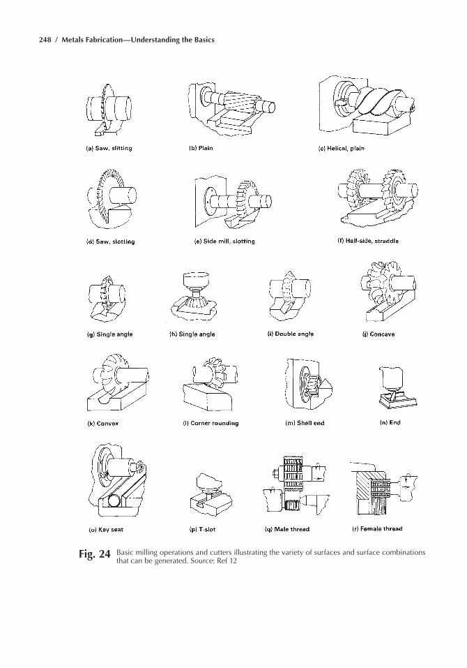
248 / Metals Fabrication—Understanding the Basics
Fig. 24 Basic milling operations and cutters illustrating the variety of surfaces and surface combinations that can be generated. Source: ref 12
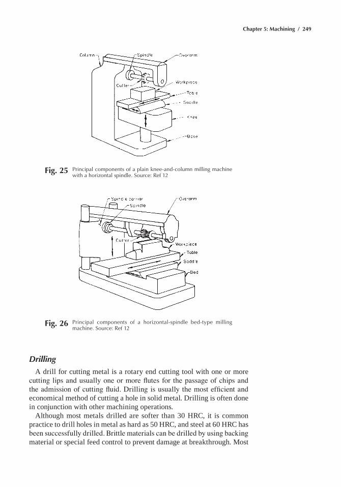
Chapter 5: Machining / 249
Drilling
a drill for cutting metal is a rotary end cutting tool with one or more cutting lips and usually one or more flutes for the passage of chips and the admission of cutting fluid. Drilling is usually the most efficient and economical method of cutting a hole in solid metal. Drilling is often done in conjunction with other machining operations.
although most metals drilled are softer than 30 hrc, it is common practice to drill holes in metal as hard as 50 hrc, and steel at 60 hrc has been successfully drilled. Brittle materials can be drilled by using backing material or special feed control to prevent damage at breakthrough. Most
Fig. 25 principal components of a plain knee-and-column milling machine with a horizontal spindle. Source: ref 12
Fig. 26 principal components of a horizontal-spindle bed-type milling machine. Source: ref 12
250 / Metals Fabrication—Understanding the Basics
drilled holes are 3.2 to 38 mm (0.125 to 1.5 in.) in diameter. however, drills are commercially available for drilling holes as small as 0.025 mm (0.001 in.) in diameter, and special drills are available as large as 152 mm (6 in.) in diameter. The length-to-diameter ratio of holes that can be successfully drilled depends on the method of driving the drill and on straightness requirements. in the simplest form of drilling (feeding a rotating twist drill into a fixed workpiece), optimal results are obtained when hole length is less than three times the diameter. however, by using special tools, equip-ment, and techniques, straight holes can be drilled in which length is more than eight times the diameter.
The basic work and tool motions that are required for drilling—relative rotation between the workpiece and the tool, with relative longitudinal feeding—also occur in a number of other machining operations. conse-quently, drilling can be done on a variety of machine tools, such as lathes, milling machines, and boring machines. Drilling machines, called drill presses, consist of a base, a column that supports a powerhead, a spindle, and a worktable, as depicted in Fig. 27. on small machines, the base rests on a bench, but on larger machines, it rests on the floor. A column on a base carries a table for the workpiece and a spindle head. The table is raised or lowered manually, often by an elevating screw, and can be clamped to the column for rigidity. some tables are round and can be swiveled. on vertical drill presses with round columns, the tables can generally be swung out from under the spindle so that the workpieces can be mounted on the base.
The heart of any drilling machine is its spindle. To drill satisfactorily, the spindle must rotate accurately and must resist whatever side forces that result during drilling. in virtually all machines, the spindle rotates in preloaded ball or tapered-roller bearings. some machines have only hand feed, while others have power feeds. Machines of this type can be equipped with a positive leadscrew for tapping and a spindle-reversing mechanism. as a rule, an adjustable stop is provided to limit the depth of travel of the quill and, with power feed, to disengage the feed or reverse a tapping spindle at a definite depth. Most machines have a Morse taper hole in the end of the spindle, but small machines often have a drill chuck attached to the end of the spindle. The spindles of fractional-horsepower drill presses are usually driven by v-belts, while larger spindles have gear transmissions, and some have multiple-speed motors. numerical control is also used.
Machining Parameters
Machining parameters that apply to all machining operations include cutting speed, feed, and depth of cut. speed is always stated in linear terms because cutter and work diameters vary and rpm is meaningless with-out peripheral speeds. Feed is reduced to feed per tooth because feeding mechanisms in various operations are so different and cutting tools may
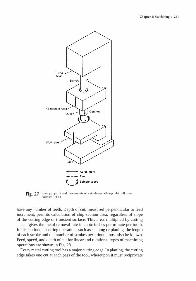
Chapter 5: Machining / 251
have any number of teeth. Depth of cut, measured perpendicular to feed increment, permits calculation of chip-section area, regardless of slope of the cutting edge or transient surface. This area, multiplied by cutting speed, gives the metal removal rate in cubic inches per minute per tooth. in discontinuous cutting operations such as shaping or planing, the length of each stroke and the number of strokes per minute must also be known. Feed, speed, and depth of cut for linear and rotational types of machining operations are shown in Fig. 28.
every metal cutting tool has a major cutting edge. in planing, the cutting edge takes one cut at each pass of the tool, whereupon it must reciprocate
Fig. 27 principal parts and movements of a single-spindle upright drill press. Source: ref 13
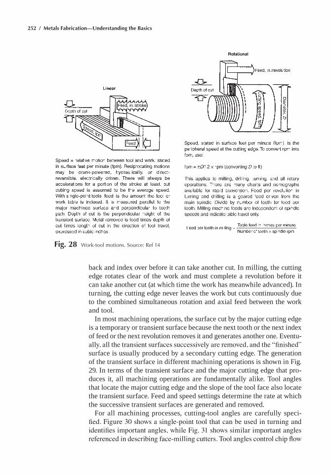
252 / Metals Fabrication—Understanding the Basics
Fig. 28 Work-tool motions. Source: ref 14
back and index over before it can take another cut. in milling, the cutting edge rotates clear of the work and must complete a revolution before it can take another cut (at which time the work has meanwhile advanced). in turning, the cutting edge never leaves the work but cuts continuously due to the combined simultaneous rotation and axial feed between the work and tool.
in most machining operations, the surface cut by the major cutting edge is a temporary or transient surface because the next tooth or the next index of feed or the next revolution removes it and generates another one. eventu-ally, all the transient surfaces successively are removed, and the “finished” surface is usually produced by a secondary cutting edge. The generation of the transient surface in different machining operations is shown in Fig. 29. in terms of the transient surface and the major cutting edge that pro-duces it, all machining operations are fundamentally alike. Tool angles that locate the major cutting edge and the slope of the tool face also locate the transient surface. Feed and speed settings determine the rate at which the successive transient surfaces are generated and removed.
For all machining processes, cutting-tool angles are carefully speci-fied. Figure 30 shows a single-point tool that can be used in turning and identifies important angles, while Fig. 31 shows similar important angles referenced in describing face-milling cutters. Tool angles control chip flow
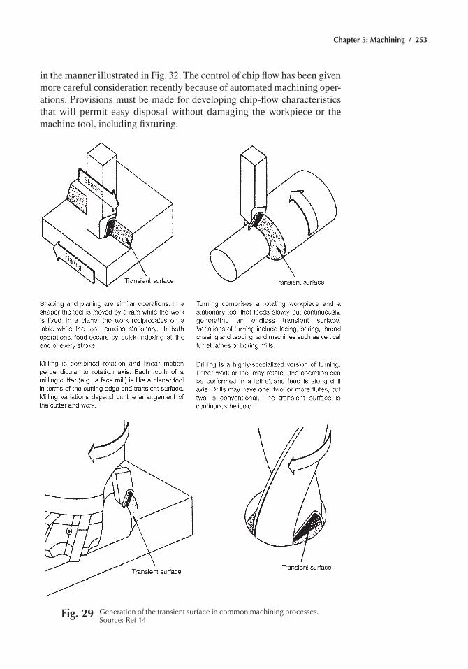
Chapter 5: Machining / 253
Fig. 29 Generation of the transient surface in common machining processes. Source: ref 14
in the manner illustrated in Fig. 32. The control of chip flow has been given more careful consideration recently because of automated machining oper-ations. Provisions must be made for developing chip-flow characteristics that will permit easy disposal without damaging the workpiece or the machine tool, including fixturing.
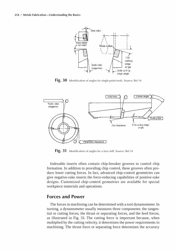
254 / Metals Fabrication—Understanding the Basics
Fig. 30 Identification of angles for single-point tools. Source: ref 14
indexable inserts often contain chip-breaker grooves to control chip formation. in addition to providing chip control, these grooves often pro-duce lower cutting forces. in fact, advanced chip-control geometries can give negative-rake inserts the force-reducing capabilities of positive-rake designs. Customized chip-control geometries are available for special workpiece materials and operations.
Forces and Power
The forces in machining can be determined with a tool dynamometer. in turning, a dynamometer usually measures three components: the tangen-tial or cutting forces, the thrust or separating forces, and the feed forces, as illustrated in Fig. 33. The cutting force is important because, when multiplied by the cutting velocity, it determines the power requirements in machining. The thrust force or separating force determines the accuracy
Fig. 31 Identification of angles for a face mill. Source: ref 14
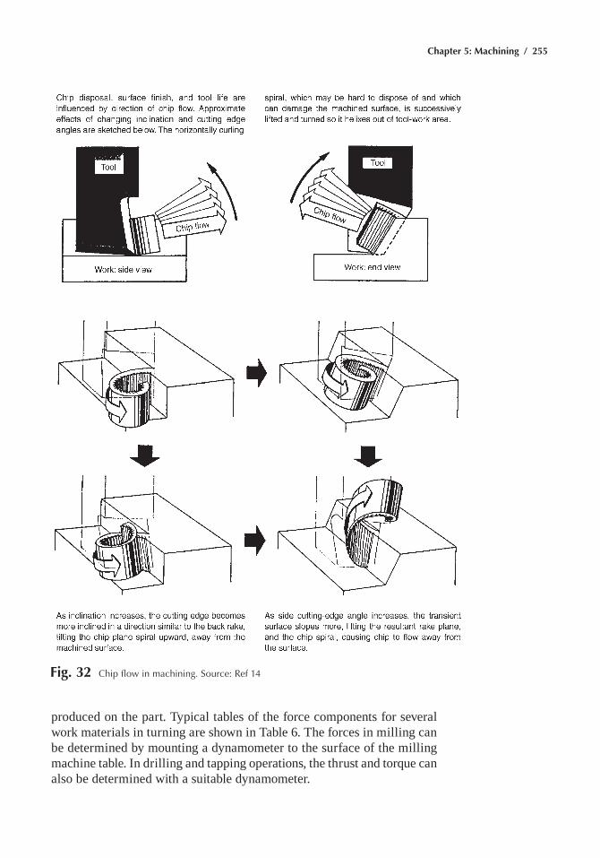
Chapter 5: Machining / 255
Fig. 32 Chip flow in machining. Source: ref 14
produced on the part. Typical tables of the force components for several work materials in turning are shown in Table 6. The forces in milling can be determined by mounting a dynamometer to the surface of the milling machine table. in drilling and tapping operations, the thrust and torque can also be determined with a suitable dynamometer.
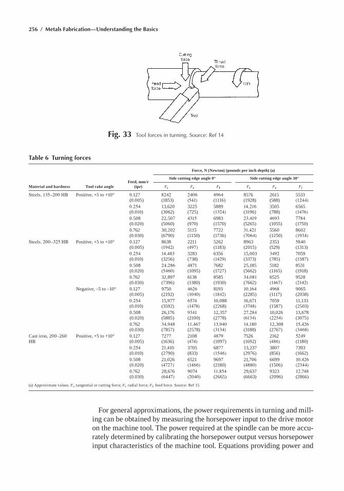
256 / Metals Fabrication—Understanding the Basics
Fig. 33 tool forces in turning. Source: ref 14
Table 6 Turning forces
Material and hardness Tool rake angleFeed, mm/r
(ipr)
Force, N (Newton) (pounds per inch depth) (a)
Side cutting edge angle 0° Side cutting edge angle 30°
Ft Fr Ff Ft Fr Ff
Steels, 135–200 HB Positive, +5 to +10° 0.127 (0.005)
8242 (1853)
2406 (541)
4964 (1116)
8576 (1928)
2615 (588)
5533 (1244)
0.254 (0.010)
13,620 (3062)
3225 (725)
5889 (1324)
14,216 (3196)
3505 (788)
6565 (1476)
0.508 (0.020)
22,507 (5060)
4315 (970)
6983 (1570)
23,419 (5265)
4693 (1055)
7784 (1750)
0.762 (0.030)
30,202 (6790)
5115 (1150)
7722 (1736)
31,421 (7064)
5560 (1250)
8602 (1934)
Steels, 200–325 HB Positive, +5 to +10° 0.127 (0.005)
8638 (1942)
2211 (497)
5262 (1183)
8963 (2015)
2353 (529)
5840 (1313)
0.254 (0.010)
14,483 (3256)
3283 (738)
6356 (1429)
15,003 (3373)
3492 (785)
7059 (1587)
0.508 (0.020)
24,286 (5460)
4871 (1095)
7682 (1727)
25,185 (5662)
5182 (1165)
8531 (1918)
0.762 (0.030)
32,897 (7396)
6138 (1380)
8585 (1930)
34,081 (7662)
6525 (1467)
9528 (2142)
negative, –5 to –10° 0.127 (0.005)
9750 (2192)
4626 (1040)
8193 (1842)
10,164 (2285)
4968 (1117)
9065 (2038)
0.254 (0.010)
15,977 (3592)
6574 (1478)
10,088 (2268)
16,671 (3748)
7059 (1587)
11,133 (2503)
0.508 (0.020)
26,176 (5885)
9341 (2100)
12,357 (2778)
27,284 (6134)
10,026 (2254)
13,678 (3075)
0.762 (0.030)
34,948 (7857)
11,467 (2578)
13,940 (3134)
14,180 (3188)
12,308 (2767)
15,426 (3468)
cast iron, 200–260 HB
Positive, +5 to +10° 0.127 (0.005)
7277 (1636)
2108 (474)
4879 (1097)
7526 (1692)
2162 (486)
5249 (1180)
0.254 (0.010)
21,410 (2790)
3705 (833)
6877 (1546)
13,237 (2976)
3807 (856)
7393 (1662)
0.508 (0.020)
21,026 (4727)
6521 (1466)
9697 (2180)
21,706 (4880)
6699 (1506)
10,426 (2344)
0.762 (0.030)
28,676 (6447)
9074 (2040)
11,854 (2665)
29,637 (6663)
9323 (2096)
12,748 (2866)
(a) approximate values. Ft, tangential or cutting force; Fr, radial force; Ff, feed force. source: ref 15
For general approximations, the power requirements in turning and mill-ing can be obtained by measuring the horsepower input to the drive motor on the machine tool. The power required at the spindle can be more accu-rately determined by calibrating the horsepower output versus horsepower input characteristics of the machine tool. equations providing power and
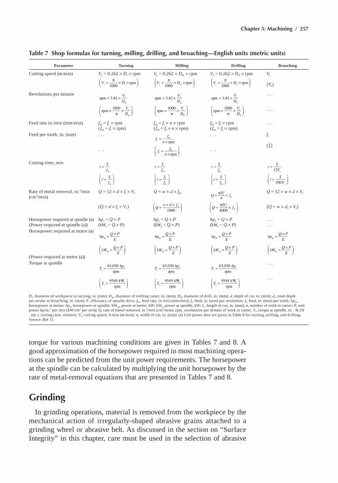
Chapter 5: Machining / 257
Table 7 Shop formulas for turning, milling, drilling, and broaching—English units (metric units)
Parameter Turning Milling Drilling Broaching
cutting speed (m/min) Vc = 0.262 ¥ Dt ¥ rpm
V D1000
rpmc t= π × ×
Vc = 0.262 ¥ Dm ¥ rpm
V D1000
rpmc m= π × ×
Vc = 0.262 ¥ Dd ¥ rpm
V D1000
rpmc d= π × ×
Vc
(Vc)
revolutions per minute= ×
=π
×
VDVD
rpm 3.82
rpm 1000
c
m
c
m
= ×
=π
×
VDVD
rpm 3.82
rpm 1000
c
m
c
m
= ×
=π
×
VDVD
rpm 3.82
rpm 1000
c
d
c
d
. . .
. . .
Feed rate in./min (mm/min) fm = fr ¥ rpm( fm = ft ¥ rpm)
fm = ft ¥ n ¥ rpm( fm = ft ¥ n ¥ rpm)
fm = ft ¥ rpm( fm = ft ¥ rpm)
. . .
Feed per tooth, in. (mm) . . .
. . .
f fn
f fn
rpm
rpm
tm
tm
=×
=×
. . .
. . .
ft
( ft)
cutting time, mint L
f
t Lf
m
m
=
=
t Lf
t Lf
m
m
=
=
t Lf
t Lf
m
m
=
=
t LV
t LV
12
100
c
c
=
=
rate of metal removal, in.3/min (cm3/min)
Q = 12 ¥ d ¥ ft ¥ Vc
(Q = d ¥ ft ¥ Vc)
Q = w ¥ d ¥ fm
= × ×
Q w d f
1000m
= π ×Q D f4
d2
m
= π ×
Q D f4000
dm
2
Q = 12 ¥ w ¥ d ¥ Vc
(Q = w ¥ dt ¥ Vc)
horsepower required at spindle (a)
(Power required at spindle (a))hps = Q ¥ P(kWs = Q ¥ P)
hps = Q ¥ P(kWs = Q ¥ P)
hps = Q ¥ P(kWs = Q ¥ P)
. . .
. . .horsepower required at motor (a)
(Power required at motor (a))
= ×hp Q PEm
= ×
kW Q P
Em
= ×hp Q PEm
= ×
kW Q P
Em
= ×hp Q PEm
= ×
kW Q P
Em
= ×hp Q PEm
= ×
kW Q P
Em
Torque at spindle=T hp63,030
rpmss
=
T 9549 kWrpms
s
=T hp63,030 rpms
s
=
T 9549 kWrpms
s
=T hp63,030 rpms
s
=
T 9549 kWrpms
s
. . .
. . .
Dt, diameter of workpiece in turning, in. (mm); Dm, diameter of milling cutter, in. (mm); Dd, diameter of drill, in. (mm); d, depth of cut, in. (mm); dt, total depth per stroke in broaching, in. (mm); E, efficiency of spindle drive; fm, feed rate, in./min (mm/min); fr, feed, in. (mm) per revolution; ft, feed, in. (mm) per tooth; hpm, horsepower at motor; hps, horsepower at spindle; kWm, power at motor, kW; kWs, power at spindle, kW; L, length of cut, in. (mm); n, number of teeth in cutter; P, unit power hp/in.3 per min (kW/cm3 per min); Q, rate of metal removed, in.3/min (cm3/min); rpm, revolutions per minute of work or cutter; Ts, torque at spindle, in. ◊ lb (n ◊ m); t, cutting time, minutes; Vc, cutting speed, ft/min (m/min); w, width of cut, in. (mm). (a) Unit power data are given in Table 8 for turning, milling, and drilling. source: ref 15
torque for various machining conditions are given in Tables 7 and 8. a good approximation of the horsepower required in most machining opera-tions can be predicted from the unit power requirements. The horsepower at the spindle can be calculated by multiplying the unit horsepower by the rate of metal-removal equations that are presented in Tables 7 and 8.
Grinding
in grinding operations, material is removed from the workpiece by the mechanical action of irregularly-shaped abrasive grains attached to a grinding wheel or abrasive belt. as discussed in the section on “surface integrity” in this chapter, care must be used in the selection of abrasive
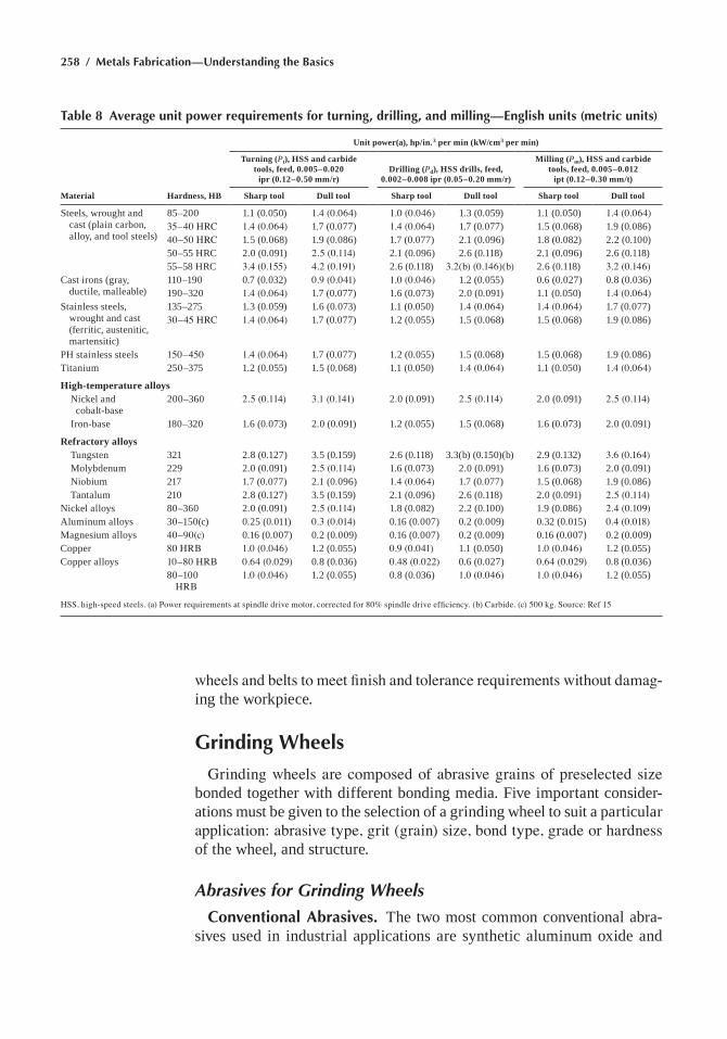
258 / Metals Fabrication—Understanding the Basics
wheels and belts to meet finish and tolerance requirements without damag-ing the workpiece.
Grinding Wheels
Grinding wheels are composed of abrasive grains of preselected size bonded together with different bonding media. Five important consider-ations must be given to the selection of a grinding wheel to suit a particular application: abrasive type, grit (grain) size, bond type, grade or hardness of the wheel, and structure.
Abrasives for Grinding Wheels
Conventional Abrasives. The two most common conventional abra-sives used in industrial applications are synthetic aluminum oxide and
Table 8 Average unit power requirements for turning, drilling, and milling—English units (metric units)
Material Hardness, HB
Unit power(a), hp/in.3 per min (kW/cm3 per min)
Turning (Pt), HSS and carbide tools, feed, 0.005–0.020
ipr (0.12–0.50 mm/r)Drilling (Pd), HSS drills, feed,
0.002–0.008 ipr (0.05–0.20 mm/r)
Milling (Pm), HSS and carbide tools, feed, 0.005–0.012
ipt (0.12–0.30 mm/t)
Sharp tool Dull tool Sharp tool Dull tool Sharp tool Dull tool
steels, wrought and cast (plain carbon, alloy, and tool steels)
85–200 1.1 (0.050) 1.4 (0.064) 1.0 (0.046) 1.3 (0.059) 1.1 (0.050) 1.4 (0.064)35–40 HRC 1.4 (0.064) 1.7 (0.077) 1.4 (0.064) 1.7 (0.077) 1.5 (0.068) 1.9 (0.086)40–50 HRC 1.5 (0.068) 1.9 (0.086) 1.7 (0.077) 2.1 (0.096) 1.8 (0.082) 2.2 (0.100)50–55 hrc 2.0 (0.091) 2.5 (0.114) 2.1 (0.096) 2.6 (0.118) 2.1 (0.096) 2.6 (0.118)55–58 hrc 3.4 (0.155) 4.2 (0.191) 2.6 (0.118) 3.2(b) (0.146)(b) 2.6 (0.118) 3.2 (0.146)
cast irons (gray, ductile, malleable)
110–190 0.7 (0.032) 0.9 (0.041) 1.0 (0.046) 1.2 (0.055) 0.6 (0.027) 0.8 (0.036)190–320 1.4 (0.064) 1.7 (0.077) 1.6 (0.073) 2.0 (0.091) 1.1 (0.050) 1.4 (0.064)
stainless steels, wrought and cast (ferritic, austenitic, martensitic)
135–275 1.3 (0.059) 1.6 (0.073) 1.1 (0.050) 1.4 (0.064) 1.4 (0.064) 1.7 (0.077)30–45 HRC 1.4 (0.064) 1.7 (0.077) 1.2 (0.055) 1.5 (0.068) 1.5 (0.068) 1.9 (0.086)
Ph stainless steels 150–450 1.4 (0.064) 1.7 (0.077) 1.2 (0.055) 1.5 (0.068) 1.5 (0.068) 1.9 (0.086)Titanium 250–375 1.2 (0.055) 1.5 (0.068) 1.1 (0.050) 1.4 (0.064) 1.1 (0.050) 1.4 (0.064)
High-temperature alloys nickel and
cobalt-base200–360 2.5 (0.114) 3.1 (0.141) 2.0 (0.091) 2.5 (0.114) 2.0 (0.091) 2.5 (0.114)
iron-base 180–320 1.6 (0.073) 2.0 (0.091) 1.2 (0.055) 1.5 (0.068) 1.6 (0.073) 2.0 (0.091)
Refractory alloys Tungsten 321 2.8 (0.127) 3.5 (0.159) 2.6 (0.118) 3.3(b) (0.150)(b) 2.9 (0.132) 3.6 (0.164) Molybdenum 229 2.0 (0.091) 2.5 (0.114) 1.6 (0.073) 2.0 (0.091) 1.6 (0.073) 2.0 (0.091) niobium 217 1.7 (0.077) 2.1 (0.096) 1.4 (0.064) 1.7 (0.077) 1.5 (0.068) 1.9 (0.086) Tantalum 210 2.8 (0.127) 3.5 (0.159) 2.1 (0.096) 2.6 (0.118) 2.0 (0.091) 2.5 (0.114)nickel alloys 80–360 2.0 (0.091) 2.5 (0.114) 1.8 (0.082) 2.2 (0.100) 1.9 (0.086) 2.4 (0.109)aluminum alloys 30–150(c) 0.25 (0.011) 0.3 (0.014) 0.16 (0.007) 0.2 (0.009) 0.32 (0.015) 0.4 (0.018)Magnesium alloys 40–90(c) 0.16 (0.007) 0.2 (0.009) 0.16 (0.007) 0.2 (0.009) 0.16 (0.007) 0.2 (0.009)copper 80 HRB 1.0 (0.046) 1.2 (0.055) 0.9 (0.041) 1.1 (0.050) 1.0 (0.046) 1.2 (0.055)copper alloys 10–80 HRB 0.64 (0.029) 0.8 (0.036) 0.48 (0.022) 0.6 (0.027) 0.64 (0.029) 0.8 (0.036)
80–100 HRB
1.0 (0.046) 1.2 (0.055) 0.8 (0.036) 1.0 (0.046) 1.0 (0.046) 1.2 (0.055)
HSS, high-speed steels. (a) Power requirements at spindle drive motor, corrected for 80% spindle drive efficiency. (b) Carbide. (c) 500 kg. Source: Ref 15
Chapter 5: Machining / 259
silicon carbide. aluminum oxide abrasives have a wide variety of proper-ties, such as toughness and friability, which can be tailored to specific job requirements. Tough aluminum oxide is used for rough grinding opera-tions; semifriable aluminum oxide is a general-purpose type; white friable aluminum oxide is used for tool grinding and for heat-sensitive materials; and seed-gel, high-purity aluminum oxide is used for precision grinding of difficult-to-grind steels and alloys. Zirconia aluminas are used in high-pressure, high-stock-removal operations on ferrous materials—they are not used for precision grinding.
silicon carbide is harder than aluminum oxide and is used primarily for grinding nonmetallic, nonferrous, and low-tensile-strength materials. green friable silicon carbide is used for the general-purpose grinding of tungsten carbide.
Superabrasives consist of diamond and cubic boron nitride (CBN). Diamond has a relatively low impact resistance and is therefore used for grinding materials such as carbides, glass, and ceramics that fracture rather than chip when ground. cubic boron nitride has a high impact resistance and exhibits optimal results in the grinding of hard ferrous materials (>50 hrc).
Types of Bonds for Grinding Wheels
in order to effectively grind a large range of materials, a variety of bonding systems are available to hold the abrasives in the wheel. The most common bonding materials are resin (phenolic), ceramic (glass), and metal (bronze). Other bond types, such as shellac, oxychloride, rubber, and silicate are available but are not commonly used. The superabra-sive wheels are also available in a metal-single-layer (MSL) specification that consists of a single layer of abrasives held together with the help of a metallic braze. Other superabrasive products, called plated wheels or e-process wheels, have a single layer of abrasives electroplated on the preform.
Grinding Fluids
Grinding fluids are introduced into grinding operations to:
• reduce and transfer heat during grinding• Lubricate during chip formation• Wash the grinding wheel or belt of loose chips and swarf• chemically aid the grinding action or machine maintenance
Grinding fluids or coolants are used almost exclusively in precision grinding applications in which metallurgical damage in ground parts must be minimized.
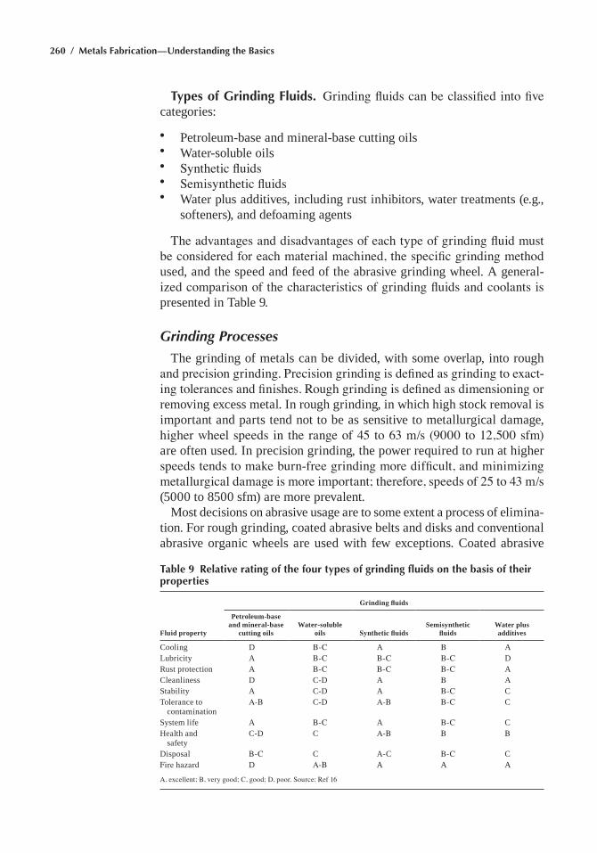
260 / Metals Fabrication—Understanding the Basics
Types of Grinding Fluids. Grinding fluids can be classified into five categories:
• Petroleum-base and mineral-base cutting oils• Water-soluble oils• Synthetic fluids• Semisynthetic fluids• Water plus additives, including rust inhibitors, water treatments (e.g.,
softeners), and defoaming agents
The advantages and disadvantages of each type of grinding fluid must be considered for each material machined, the specific grinding method used, and the speed and feed of the abrasive grinding wheel. a general-ized comparison of the characteristics of grinding fluids and coolants is presented in Table 9.
Grinding Processes
The grinding of metals can be divided, with some overlap, into rough and precision grinding. Precision grinding is defined as grinding to exact-ing tolerances and finishes. Rough grinding is defined as dimensioning or removing excess metal. in rough grinding, in which high stock removal is important and parts tend not to be as sensitive to metallurgical damage, higher wheel speeds in the range of 45 to 63 m/s (9000 to 12,500 sfm) are often used. in precision grinding, the power required to run at higher speeds tends to make burn-free grinding more difficult, and minimizing metallurgical damage is more important; therefore, speeds of 25 to 43 m/s (5000 to 8500 sfm) are more prevalent.
Most decisions on abrasive usage are to some extent a process of elimina-tion. For rough grinding, coated abrasive belts and disks and conventional abrasive organic wheels are used with few exceptions. coated abrasive
Table 9 Relative rating of the four types of grinding fluids on the basis of their properties
Fluid property
Grinding fluids
Petroleum-base and mineral-base
cutting oilsWater-soluble
oils Synthetic fluidsSemisynthetic
fluidsWater plus additives
cooling D B-C a B aLubricity a B-C B-C B-C Drust protection a B-C B-C B-C acleanliness D c-D a B astability a c-D a B-C cTolerance to
contaminationA-B c-D A-B B-C c
system life a B-C a B-C chealth and
safetyc-D c A-B B B
Disposal B-C c a-c B-C cFire hazard D A-B a a a
A, excellent; B, very good; C, good; D, poor. Source: Ref 16
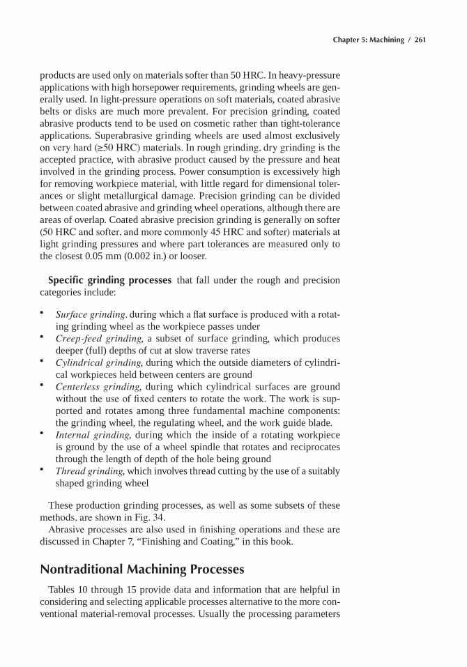
Chapter 5: Machining / 261
products are used only on materials softer than 50 hrc. in heavy-pressure applications with high horsepower requirements, grinding wheels are gen-erally used. in light-pressure operations on soft materials, coated abrasive belts or disks are much more prevalent. For precision grinding, coated abrasive products tend to be used on cosmetic rather than tight-tolerance applications. superabrasive grinding wheels are used almost exclusively on very hard (≥50 HRC) materials. In rough grinding, dry grinding is the accepted practice, with abrasive product caused by the pressure and heat involved in the grinding process. Power consumption is excessively high for removing workpiece material, with little regard for dimensional toler-ances or slight metallurgical damage. Precision grinding can be divided between coated abrasive and grinding wheel operations, although there are areas of overlap. coated abrasive precision grinding is generally on softer (50 HRC and softer, and more commonly 45 HRC and softer) materials at light grinding pressures and where part tolerances are measured only to the closest 0.05 mm (0.002 in.) or looser.
Specific grinding processes that fall under the rough and precision categories include:
• Surface grinding, during which a flat surface is produced with a rotat-ing grinding wheel as the workpiece passes under
• Creep-feed grinding, a subset of surface grinding, which produces deeper (full) depths of cut at slow traverse rates
• Cylindrical grinding, during which the outside diameters of cylindri-cal workpieces held between centers are ground
• Centerless grinding, during which cylindrical surfaces are ground without the use of fixed centers to rotate the work. The work is sup-ported and rotates among three fundamental machine components: the grinding wheel, the regulating wheel, and the work guide blade.
• Internal grinding, during which the inside of a rotating workpiece is ground by the use of a wheel spindle that rotates and reciprocates through the length of depth of the hole being ground
• Thread grinding, which involves thread cutting by the use of a suitably shaped grinding wheel
These production grinding processes, as well as some subsets of these methods, are shown in Fig. 34.
Abrasive processes are also used in finishing operations and these are discussed in chapter 7, “Finishing and coating,” in this book.
Nontraditional Machining Processes
Tables 10 through 15 provide data and information that are helpful in considering and selecting applicable processes alternative to the more con-ventional material-removal processes. Usually the processing parameters
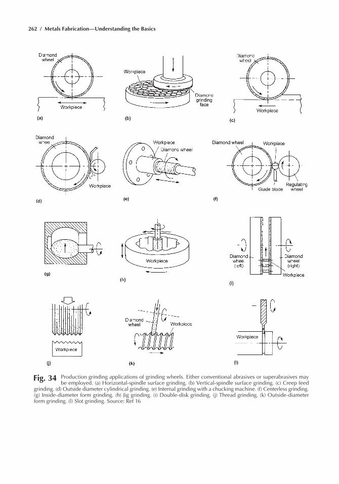
262 / Metals Fabrication—Understanding the Basics
Fig. 34 production grinding applications of grinding wheels. either conventional abrasives or superabrasives may be employed. (a) horizontal-spindle surface grinding. (b) Vertical-spindle surface grinding. (c) Creep feed
grinding. (d) Outside diameter cylindrical grinding. (e) Internal grinding with a chucking machine. (f) Centerless grinding. (g) Inside-diameter form grinding. (h) Jig grinding. (i) Double-disk grinding. (j) thread grinding. (k) Outside-diameter form grinding. (l) Slot grinding. Source: ref 16
Chapter 5: Machining / 263
Table 10 Process summary chart for electrochemical machining and electrical discharge machining
Process factor Electrochemical machining (ECM) Electrical discharge machining (EDM)
Principle controlled metal removal by anodic dissolution. Direct current (dc) passes through flowing film of conductive solution that separates workpiece from electrode tool. Workpiece is anode; tool is cathode.
Metal is removed by rapid spark discharges between an electrode and a conductive workpiece separated by a 0.127–0.889 mm (0.005–0.035 in.) gap filled with dielectric fluid and metal particulates. The workpiece material is melted, vaporized in part, and expelled from the gap.
equipment Machine tool must be rigid to withstand high fluid separating forces; must protect mechanical and electrical systems for corrosive electrolytes, and have provisions for venting of work areas; dc power source; electrolyte system, including pumps, filters, storage tanks, and heat exchanger; electrolyte clarifier may be required; servomechanism for process control optional
rigid machine tool for close control of spark gap; eDM power supply; servomechanism to control electrode movement; dielectric fluid pressure or vacuum system and filter. Computer numerical control and tool change capability available.
Typical applications high-strengh, high-hardness materials; high-temperature alloy forgings; odd-shaped holes and cavities; jet engine blade airfoils; small deep holes; jet engine blade cooling holes; deburring; face turning of disks; tungsten carbide machining; etching of numbers and letters in hard steels; selective machining of one material from another, enlarging inside diameters
Manufacture of dies (stamping, cold heading, forging, injection molding); carbide-forming tools; tungsten parts; burr-free parts; odd-shaped holes and cavities; small-diameter deep holes; high-strength and high-hardness materials; narrow slots (0.051–0.305 mm, or 0.002–0.012 in., wide); honeycomb cores and assemblies; other fragile parts
operating parameters and typical values
Gap voltage: 4–24Amperage: Commercial units 50–40,000gap spacing: end 0.025–0.508 mm (0.001–0.020 in.
side 0.127–0.508 mm (0.005–0.020 in.)Electrolyte flow: 6–60 m/s (20–200 ft/s)Electrolyte pressure: 70–2760 kPa (10–400 psi)Electrolyte temperature: 42–83 °C (75–150 °F)electrolyte downfeed: 0.508–19.05 mm/min (0.020–
0.750 in./min) at 100–2000 amp/in.2
Electrodes: Brass, copper, stainless steel, titanium, platinum, sintered copper-tungsten, aluminum, graphite
electrolyte: Propretary mixtures, sodium chloride solution up to 2.5 lb/gal; sodium nitrate solution up to 5 lb/gal; sulfuric acid 30%, sodium nitrate and sodium chloride mix
Workpiece: Must be electrically conductive
voltage: Up to 300amperage: commercial units 0.1–500Frequency: 200–500,000 HzDielectric fluid pressure: 0–480 kPa (0–70 psi);
sometimes in vacuum (28 in. hg)electrode materials: graphite, copper, brass, copper-
tungsten, silver-tungsten, tungsten, and tungsten carbide
Fluids: hydrocarbon (petroleum) oilsWorkpiece: Must be electrically conductivePower source rating: single units up to 500 amp
Tolerances Practical: ±0.127 mm (±0.005 in.) Possible: ±0.0127 mm (±0.0005 in.)
Practical: ±0.0508–0.127 mm (0.002–0.005 in.) Possible: ±0.00254–0.0127 mm (0.0001–0.0005 in.)
surface 4 to 5 Ra can be attained. no heat-affected surface or burrs created. guard against selective etching in remote areas exposed to electrolyte by shields or dams.
Finish is affected by removal rate: (0.015 in.3/h-30 Ra) (0.5 in.3/h-200 Ra) (3.0 in.3/h-400 Ra) Heat-affected zone: 0.00254–0.0127 mm (0.0001– 0.005 in.)
Practical removal rates approximately 0.1 in.3/min/1000 amp or 1 in.3/min for a 10,000 amp unit
(0.01–25 in.3/h) depending on tolerances and finish requirements and eDM parameters
Machining characteristics no electrode wear; process may produce overcut, taper, and corner radii depending on tool design; observed values; taper 0.025 mm (0.001 in.) over entire depth, overcut 0.127 mm (0.005 in.), corner radius 0.381 mm (0.015 in.); tools subject to damage by arcing if process malfunctions; no machining stresses introduced; burr-free machining
Produces taper and overcut (finished cavity minus original electrode size) in workpiece, also corner radii. electrode wear ratio (Wr) measured and expressed as:
Wear ratio (Wr) = (volume of work removed)/(volume of electrode consumed)
orWear ratio (Wr) = (depth of cut)/(length of electrode
consumed)Typical values: Taper, 0.0127–0.127 mm/mm
(0.0005–0.005 in./in.) per side; overcut 0.00508–0.889 mm/side (0.0002–0.035 in./side); minimum corner radius 0.0127 mm (0.0005 in.) or equal to overcut
Typical electrode wear ratios: Metallic electrodes 3:1; carbon 3:1 to 100:1
source: ref 17
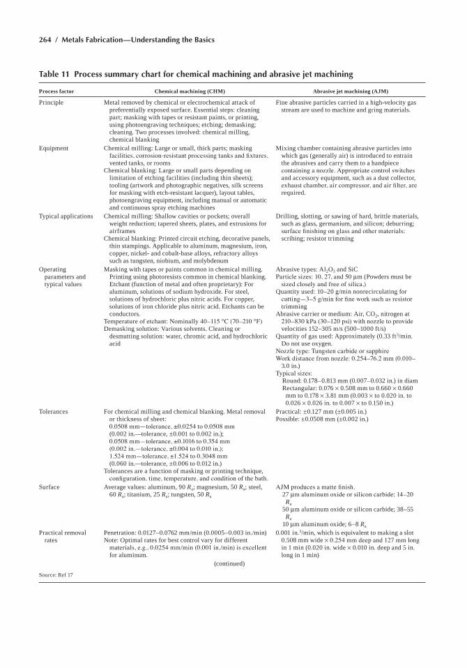
264 / Metals Fabrication—Understanding the Basics
Table 11 Process summary chart for chemical machining and abrasive jet machining
Process factor Chemical machining (CHM) Abrasive jet machining (AJM)
Principle Metal removed by chemical or electrochemical attack of preferentially exposed surface. essential steps: cleaning part; masking with tapes or resistant paints, or printing, using photoengraving techniques; etching; demasking; cleaning. Two processes involved: chemical milling, chemical blanking
Fine abrasive particles carried in a high-velocity gas stream are used to machine and gring materials.
equipment chemical milling: Large or small, thick parts; masking facilities, corrosion-resistant processing tanks and fixtures, vented tanks, or rooms
chemical blanking: Large or small parts depending on limitation of etching facilities (including thin sheets); tooling (artwork and photographic negatives, silk screens for masking with etch-resistant lacquer), layout tables, photoengraving equipment, including manual or automatic and continuous spray etching machines
Mixing chamber containing abrasive particles into which gas (generally air) is introduced to entrain the abrasives and carry them to a handpiece containing a nozzle. Appropriate control switches and accessory equipment, such as a dust collector, exhaust chamber, air compressor, and air filter, are required.
Typical applications chemical milling: shallow cavities or pockets; overall weight reduction; tapered sheets, plates, and extrusions for airframes
chemical blanking: Printed circuit etching, decorative panels, thin stampings. applicable to aluminum, magnesium, iron, copper, nickel- and cobalt-base alloys, refractory alloys such as tungsten, niobium, and molybdenum
Drilling, slotting, or sawing of hard, brittle materials, such as glass, germanium, and silicon; deburring; surface finishing on glass and other materials; scribing; resistor trimming
operating parameters and typical values
Masking with tapes or paints common in chemical milling. Printing using photoresists common in chemical blanking. etchant (function of metal and often proprietary): For aluminum, solutions of sodium hydroxide. For steel, solutions of hydrochloric plus nitric acids. For copper, solutions of iron chloride plus nitric acid. etchants can be conductors.
Temperature of etchant: Nominally 40–115 °C (70–210 °F)Demasking solution: various solvents. cleaning or
desmutting solution: water, chromic acid, and hydrochloric acid
abrasive types: al2o3 and sicParticle sizes: 10, 27, and 50 mm (Powders must be
sized closely and free of silica.)Quantity used: 10–20 g/min nonrecirculating for
cutting—3–5 g/min for fine work such as resistor trimming
abrasive carrier or medium: air, co2, nitrogen at 210–830 kPa (30–120 psi) with nozzle to provide velocities 152–305 m/s (500–1000 ft/s)
Quantity of gas used: approximately (0.33 ft3/min. Do not use oxygen.
Nozzle type: Tungsten carbide or sapphireWork distance from nozzle: 0.254–76.2 mm (0.010–
3.0 in.)Typical sizes: round: 0.178–0.813 mm (0.007–0.032 in.) in diam rectangular: 0.076 ¥ 0.508 mm to 0.660 ¥ 0.660
mm to 0.178 ¥ 3.81 mm (0.003 ¥ to 0.020 in. to 0.026 ¥ 0.026 in. to 0.007 ¥ to 0.150 in.)
Tolerances For chemical milling and chemical blanking. Metal removal or thickness of sheet: 0.0508 mm—tolerance, ±0.0254 to 0.0508 mm (0.002 in.—tolerance, ±0.001 to 0.002 in.); 0.0508 mm—tolerance, ±0.1016 to 0.354 mm (0.002 in.—tolerance, ±0.004 to 0.010 in.); 1.524 mm—tolerance, ±1.524 to 0.3048 mm (0.060 in.—tolerance, ±0.006 to 0.012 in.)
Tolerances are a function of masking or printing technique, configuration, time, temperature, and condition of the bath.
Practical: ±0.127 mm (±0.005 in.) Possible: ±0.0508 mm (±0.002 in.)
surface average values: aluminum, 90 Ra; magnesium, 50 Ra; steel, 60 Ra; titanium, 25 Ra; tungsten, 50 Ra
AJM produces a matte finish. 27 mm aluminum oxide or silicon carbide; 14–20
Ra 50 mm aluminum oxide or silicon carbide; 38–55
Ra 10 mm aluminum oxide; 6–8 Ra
Practical removal rates
Penetration: 0.0127–0.0762 mm/min (0.0005–0.003 in./min)note: optimal rates for best control vary for different
materials, e.g., 0.0254 mm/min (0.001 in./min) is excellent for aluminum.
0.001 in.3/min, which is equivalent to making a slot 0.508 mm wide ¥ 0.254 mm deep and 127 mm long in 1 min (0.020 in. wide ¥ 0.010 in. deep and 5 in. long in 1 min)
(continued)
source: ref 17
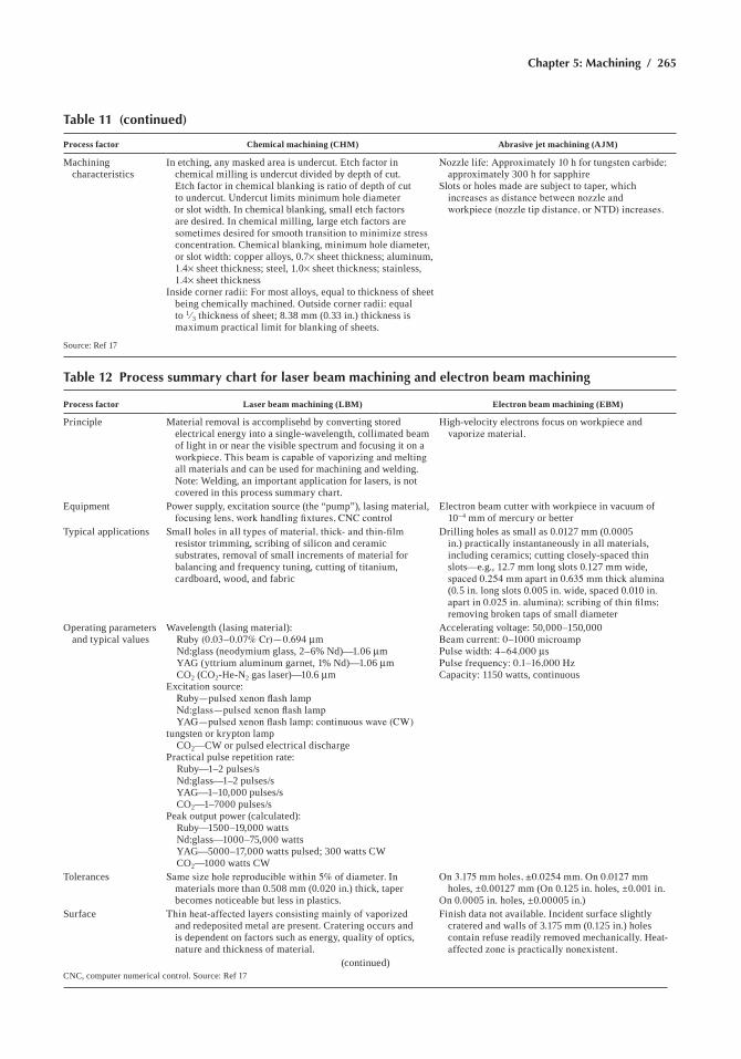
Chapter 5: Machining / 265
Process factor Chemical machining (CHM) Abrasive jet machining (AJM)
Machining characteristics
in etching, any masked area is undercut. etch factor in chemical milling is undercut divided by depth of cut. etch factor in chemical blanking is ratio of depth of cut to undercut. Undercut limits minimum hole diameter or slot width. in chemical blanking, small etch factors are desired. in chemical milling, large etch factors are sometimes desired for smooth transition to minimize stress concentration. chemical blanking, minimum hole diameter, or slot width: copper alloys, 0.7¥ sheet thickness; aluminum, 1.4¥ sheet thickness; steel, 1.0¥ sheet thickness; stainless, 1.4¥ sheet thickness
inside corner radii: For most alloys, equal to thickness of sheet being chemically machined. outside corner radii: equal to 1 ⁄3 thickness of sheet; 8.38 mm (0.33 in.) thickness is maximum practical limit for blanking of sheets.
Nozzle life: Approximately 10 h for tungsten carbide; approximately 300 h for sapphire
slots or holes made are subject to taper, which increases as distance between nozzle and workpiece (nozzle tip distance, or NTD) increases.
source: ref 17
Table 11 (continued)
Table 12 Process summary chart for laser beam machining and electron beam machining
Process factor Laser beam machining (LBM) Electron beam machining (EBM)
Principle Material removal is accomplisehd by converting stored electrical energy into a single-wavelength, collimated beam of light in or near the visible spectrum and focusing it on a workpiece. This beam is capable of vaporizing and melting all materials and can be used for machining and welding. note: Welding, an important application for lasers, is not covered in this process summary chart.
high-velocity electrons focus on workpiece and vaporize material.
equipment Power supply, excitation source (the “pump”), lasing material, focusing lens, work handling fixtures, CNC control
electron beam cutter with workpiece in vacuum of 10–4 mm of mercury or better
Typical applications Small holes in all types of material, thick- and thin-film resistor trimming, scribing of silicon and ceramic substrates, removal of small increments of material for balancing and frequency tuning, cutting of titanium, cardboard, wood, and fabric
Drilling holes as small as 0.0127 mm (0.0005 in.) practically instantaneously in all materials, including ceramics; cutting closely-spaced thin slots—e.g., 12.7 mm long slots 0.127 mm wide, spaced 0.254 mm apart in 0.635 mm thick alumina (0.5 in. long slots 0.005 in. wide, spaced 0.010 in. apart in 0.025 in. alumina); scribing of thin films; removing broken taps of small diameter
operating parameters and typical values
Wavelength (lasing material): Ruby (0.03–0.07% Cr)—0.694 mm nd:glass (neodymium glass, 2–6% nd)—1.06 mm Yag (yttrium aluminum garnet, 1% nd)—1.06 mm co2 (co2-he-n2 gas laser)—10.6 mmexcitation source: Ruby—pulsed xenon flash lamp Nd:glass—pulsed xenon flash lamp YAG—pulsed xenon flash lamp; continuous wave (CW) tungsten or krypton lamp co2—cW or pulsed electrical dischargePractical pulse repetition rate: ruby—1–2 pulses/s nd:glass—1–2 pulses/s Yag—1–10,000 pulses/s co2—1–7000 pulses/sPeak output power (calculated): ruby—1500–19,000 watts nd:glass—1000–75,000 watts Yag—5000–17,000 watts pulsed; 300 watts cW co2—1000 watts cW
accelerating voltage: 50,000–150,000Beam current: 0–1000 microampPulse width: 4–64,000 msPulse frequency: 0.1–16,000 Hzcapacity: 1150 watts, continuous
Tolerances Same size hole reproducible within 5% of diameter. In materials more than 0.508 mm (0.020 in.) thick, taper becomes noticeable but less in plastics.
On 3.175 mm holes, ±0.0254 mm. On 0.0127 mm holes, ±0.00127 mm (on 0.125 in. holes, ±0.001 in.
on 0.0005 in. holes, ±0.00005 in.)surface Thin heat-affected layers consisting mainly of vaporized
and redeposited metal are present. cratering occurs and is dependent on factors such as energy, quality of optics, nature and thickness of material.
Finish data not available. incident surface slightly cratered and walls of 3.175 mm (0.125 in.) holes contain refuse readily removed mechanically. heat-affected zone is practically nonexistent.
(continued)cnc, computer numerical control. source: ref 17
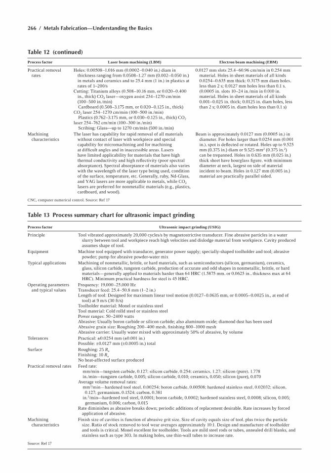
266 / Metals Fabrication—Understanding the Basics
Table 12 (continued)
Process factor Laser beam machining (LBM) Electron beam machining (EBM)
Practical removal rates
Holes: 0.00508–1.016 mm (0.0002–0.040 in.) diam in thickness ranging from 0.0508–1.27 mm (0.002–0.050 in.) in metals and ceramics and to 25.4 mm (1 in.) in plastics at rates of 1–200/s
Cutting: Titanium alloys (0.508–10.16 mm, or 0.020–0.400 in., thick) co2 laser—oxygen assist 254–1270 cm/min (100–500 in./min)
cardboard (0.508–3.175 mm, or 0.020–0.125 in., thick) co2 laser 254–1270 cm/min (100–500 in./min) Plastics (0.762–3.175 mm, or 0.030–0.125 in., thick) co2 laser 254–762 cm/min (100–300 in./min) scribing: glass—up to 1270 cm/min (500 in./min)
0.0127 mm slots 25.4–60.96 cm/min in 0.254 mm material. holes in sheet materials of all kinds 0.0254–0.635 mm thick; 0.3175 mm diam holes, less than 2 s; 0.0127 mm holes less than 0.1 s. (0.0005 in. slots 10–24 in./min in 0.010 in. material. holes in sheet materials of all kinds 0.001–0.025 in. thick; 0.0125 in. diam holes, less than 2 s; 0.0005 in. diam holes less than 0.1 s)
Machining characteristics
The laser has capability for rapid removal of all materials without contact of laser with workpiece and special capability for micromachining and for machining at difficult angles and in inaccessible areas. Lasers have limited applicability for materials that have high thermal conductivity and high reflectivity (poor spectral absorptance). spectral absorptance of materials also varies with the wavelength of the laser type being used, condition of the surface, temperature, etc. generally, ruby, nd-glass, and Yag lasers are more applicable to metals, while co2 lasers are preferred for nonmetallic materials (e.g., plastics, cardboard, and wood).
Beam is approximately 0.0127 mm (0.0005 in.) in diameter. For holes larger than 0.0254 mm (0.001 in.), spot is deflected or rotated. Holes up to 9.525 mm (0.375 in.) diam or 9.525 mm2 (0.375 in.2) can be trepanned. holes in 0.635 mm (0.025 in.) thick sheet have hourglass figure, with minimum diameter at neck, largest on side of material incident to beam. holes in 0.127 mm (0.005 in.) material are practically parallel sided.
cnc, computer numerical control. source: ref 17
Table 13 Process summary chart for ultrasonic impact grinding
Process factor Ultrasonic impact grinding (USIG)
Principle Tool vibrated approximately 20,000 cycles/s by magnetostrictive transducer. Fine abrasive particles in a water slurry between tool and workpiece reach high velocities and dislodge material from workpiece. cavity produced assumes shape of tool.
equipment Machine tool equipped with transducer, generator power supply; specially-shaped toolholder and tool; abrasive powder; pump for abrasive powder-water mix
Typical applications Machining of nonmetallic, brittle, or hard materials, such as semiconductors (silicon, germanium), ceramics, glass, silicon carbide, tungsten carbide, production of accurate and odd shapes in nonmetallic, brittle, or hard materials—generally applied to materials harder than 64 HRC (1.5875 mm, or 0.0625 in., thickness max at 64 HRC). Minimum practical hardness for steel is 45 HRC.
operating parameters and typical values
Frequency: 19,000–25,000 HzTransducer feed: 25.4–50.8 mm (1–2 in.)Length of tool: Designed for maximum linear tool motion (0.0127–0.0635 mm, or 0.0005–0.0025 in., at end of
tool) at 9 m/s (30 ft/s)Toolholder material: Monel or stainless steelTool material: cold rolld steel or stainless steelPower ranges: 50–2400 wattsabrasive: Usually boron carbide or silicon carbide; also aluminum oxide; diamond dust has been usedAbrasive grain size: Roughing 200–400 mesh, finishing 800–1000 meshabrasive carrier: Usually water mixed with approximately 50% of abrasive, by volume
Tolerances Practical: ±0.0254 mm (±0.001 in.)Possible: ±0.0127 mm (±0.0005 in.) total
surface roughing: 25 RaFinishing: 10 Rano heat-affected surface produced
Practical removal rates Feed rate: mm/min—tungsten carbide, 0.127; silicon carbide, 0.254; ceramics, 1.27; silicon (pure), 1.778 in./min—tungsten carbide, 0.005; silicon carbide, 0.010; ceramics, 0.050; silicon (pure), 0.070average volume removal rates: mm3/min—hardened tool steel, 0.00254; boron carbide, 0.00508; hardened stainless steel, 0.02032; silicon,
0.127; germanium, 0.1524; carbon, 0.381 in.3/min—hardened tool steel, 0.0001; boron carbide, 0.0002; hardened stainless steel, 0.0008; silicon, 0.005;
germanium, 0.006; carbon, 0.015rate diminishes as abrasive breaks down; periodic additions of replacement desirable. rate increases by forced
application of abrasive.Machining
characteristicsFinish size of cavities is function of abrasive grit size. Size of cavity equals size of tool, plus twice the particle
size. Ratio of stock removed to tool wear averages approximately 10:1. Design and manufacture of toolholder and tools is critical. Monel excellent for toolholder. Tools are mild steel rods or tubes, annealed drill blanks, and stainless such as type 303. in making holes, use thin-wall tubes to increase rate.
source: ref 17
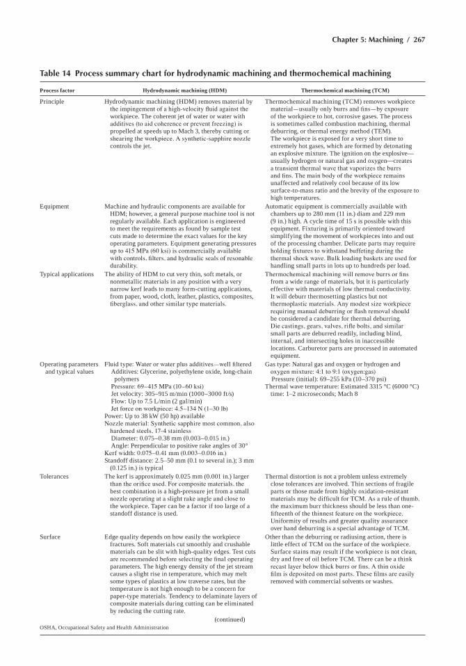
Chapter 5: Machining / 267
Table 14 Process summary chart for hydrodynamic machining and thermochemical machining
Process factor Hydrodynamic machining (HDM) Thermochemical machining (TCM)
Principle hydrodynamic machining (hDM) removes material by the impingement of a high-velocity fluid against the workpiece. The coherent jet of water or water with additives (to aid coherence or prevent freezing) is propelled at speeds up to Mach 3, thereby cutting or shearing the workpiece. A synthetic-sapphire nozzle controls the jet.
Thermochemical machining (TcM) removes workpiece material—usually only burrs and fins—by exposure of the workpiece to hot, corrosive gases. The process is sometimes called combustion machining, thermal deburring, or thermal energy method (TeM). The workpiece is exposed for a very short time to extremely hot gases, which are formed by detonating an explosive mixture. The ignition on the explosive—usually hydrogen or natural gas and oxygen—creates a transient thermal wave that vaporizes the burrs and fins. The main body of the workpiece remains unaffected and relatively cool because of its low surface-to-mass ratio and the brevity of the exposure to high temperatures.
equipment Machine and hydraulic components are available for hDM; however, a general purpose machine tool is not regularly available. each application is engineered to meet the requirements as found by sample test cuts made to determine the exact values for the key operating parameters. equipment generating pressures up to 415 MPa (60 ksi) is commercially available with controls, filters, and hydraulic seals of resonable durability.
automatic equipment is commercially available with chambers up to 280 mm (11 in.) diam and 229 mm (9 in.) high. a cycle time of 15 s is possible with this equipment. Fixturing is primarily oriented toward simplifying the movement of workpieces into and out of the processing chamber. Delicate parts may require holding fixtures to withstand buffeting during the thermal shock wave. Bulk loading baskets are used for handling small parts in lots up to hundreds per load.
Typical applications The ability of hDM to cut very thin, soft metals, or nonmetallic materials in any position with a very narrow kerf leads to many form-cutting applications, from paper, wood, cloth, leather, plastics, composites, fiberglass, and other similar type materials.
Thermochemical machining will remove burrs or fins from a wide range of materials, but it is particularly effective with materials of low thermal conductivity. it will deburr thermosetting plastics but not thermoplastic materials. Any modest size workpiece requiring manual deburring or flash removal should be considered a candidate for thermal deburring. Die castings, gears, valves, rifle bolts, and similar small parts are deburred readily, including blind, internal, and intersecting holes in inaccessible locations. carburetor parts are processed in automated equipment.
operating parameters and typical values
Fluid type: Water or water plus additives—well filtered additives: glycerine, polyethylene oxide, long-chain
polymers Pressure: 69–415 MPa (10–60 ksi) Jet velocity: 305–915 m/min (1000–3000 ft/s) Flow: Up to 7.5 L/min (2 gal/min) Jet force on workpiece: 4.5–134 N (1–30 lb)Power: Up to 38 kW (50 hp) availableNozzle material: Synthetic sapphire most common, also
hardened steels, 17-4 stainless Diameter: 0.075–0.38 mm (0.003–0.015 in.) angle: Perpendicular to positive rake angles of 30°Kerf width: 0.075–0.41 mm (0.003–0.016 in.)standoff distance: 2.5–50 mm (0.1 to several in.); 3 mm
(0.125 in.) is typical
gas type: natural gas and oxygen or hydrogen and oxygen mixture: 4:1 to 9:1 (oxygen:gas)
Pressure (initial): 69–255 kPa (10–370 psi)Thermal wave temperature: estimated 3315 °c (6000 °c)
time: 1–2 microseconds; Mach 8
Tolerances The kerf is approximately 0.025 mm (0.001 in.) larger than the orifice used. For composite materials, the best combination is a high-pressure jet from a small nozzle operating at a slight rake angle and close to the workpiece. Taper can be a factor if too large of a standoff distance is used.
Thermal distortion is not a problem unless extremely close tolerances are involved. Thin sections of fragile parts or those made from highly oxidation-resistant materials may be difficult for TCM. As a rule of thumb, the maximum burr thickness should be less than one-fifteenth of the thinnest feature on the workpiece. Uniformity of results and greater quality assurance over hand deburring is a special advantage of TcM.
surface edge quality depends on how easily the workpiece fractures. soft materials cut smoothly and crushable materials can be slit with high-quality edges. Test cuts are recommended before selecting the final operating parameters. The high energy density of the jet stream causes a slight rise in temperature, which may melt some types of plastics at low traverse rates, but the temperature is not high enough to be a concern for paper-type materials. Tendency to delaminate layers of composite materials during cutting can be eliminated by reducing the cutting rate.
other than the deburring or radiusing action, there is little effect of TcM on the surface of the workpiece. surface stains may result if the workpiece is not clean, dry and free of oil before TcM. There can be a think recast layer below thick burrs or fins. A thin oxide film is deposited on most parts. These films are easily removed with commercial solvents or washes.
(continued)osha, occupational safety and health administration
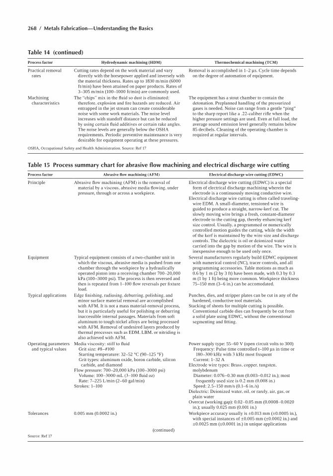
268 / Metals Fabrication—Understanding the Basics
Process factor Hydrodynamic machining (HDM) Thermochemical machining (TCM)
Practical removal rates
cutting rates depend on the work material and vary directly with the horsepower applied and inversely with the material thickness. rates up to 1830 m/min (6000 ft/min) have been attained on paper products. rates of 3–305 m/min (100–1000 ft/min) are commonly used.
removal is accomplished in 1–2 ms. cycle time depends on the degree of automation of equipment.
Machining characteristics
The “chips” mix in the fluid so dust is eliminated; therefore, explosion and fire hazards are reduced. Air entrapped in the jet stream can create considerable noise with some work materials. The noise level increases with standoff distance but can be reduced by using certain fluid additives or certain rake angles. The noise levels are generally below the osha requirements. Periodic preventive maintenance is very desirable for equipment operating at these pressures.
The equipment has a stout chamber to contain the detonation. Preplanned handling of the pressurized gases is needed. noise can range from a gentle “ping” to the sharp report like a .22-caliber rifle when the higher pressure settings are used. even at full load, the average sound emission level generally remains below 85 decibels. cleaning of the operating chamber is required at regular intervals.
osha, occupational safety and health administration. source: ref 17
Table 14 (continued)
Table 15 Process summary chart for abrasive flow machining and electrical discharge wire cutting
Process factor Abrasive flow machining (AFM) Electrical discharge wire cutting (EDWC)
Principle Abrasive flow machining (AFM) is the removal of material by a viscous, abrasive media flowing, under pressure, through or across a workpiece.
electrical discharge wire cutting (eDWc) is a special form of electrical discharge machining wherein the electrode is a continuously moving conductive wire.
electrical discharge wire cutting is often called traveling-wire eDM. a small-diameter, tensioned wire is guided to produce a straight, narrow-kerf cut. The slowly moving wire brings a fresh, constant-diameter electrode to the cutting gap, thereby enhancing kerf size control. Usually, a programmed or numerically controlled motion guides the cutting, while the width of the kerf is maintained by the wire size and discharge controls. The dielectric is oil or deionized water carried into the gap by motion of the wire. The wire is inexpensive enough to be used only once.
equipment Typical equipment consists of a two-chamber unit in which the viscous, abrasive media is pushed from one chamber through the workpiece by a hydraulically operated piston into a receiving chamber 700–20,000 kPa (100–3000 psi). The process is then reversed and then is repeated from 1–100 flow reversals per fixture load.
several manufacturers regularly build eDWc equipment with numerical control (nc), tracer controls, and all programming accessories. Table motions as much as 0.6 by 1 m (2 by 3 ft) have been made, with 0.3 by 0.3 m (1 by 1 ft) being more common. Workpiece thickness 75–150 mm (3–6 in.) can be accomodated.
Typical applications Edge finishing, radiusing, deburring, polishing, and minor surface material removal are accomplished with aFM. it is not a mass material-removal process, but it is particularly useful for polishing or deburring inaccessible internal passages. Materials from soft aluminum to tough nickel alloys are being processed with aFM. removal of undesired layers produced by thermal processes such as EDM, LBM, or nitriding is also achieved with aFM.
Punches, dies, and stripper plates can be cut in any of the hardened, conductive tool materials.
stacking of sheets for multiple cutting is possible. conventional carbide dies can frequently be cut from a solid plate using eDWc, without the conventional segmenting and fitting.
operating parameters and typical values
Media viscosity: stiff to fluid Grit size: #8–#100 starting temperature: 32–52 °c (90–125 °F) grit types: aluminum oxide, boron carbide, silicon
carbide, and diamondFlow pressure: 700–20,000 kPa (100–3000 psi) Volume: 100–3000 mL (3–100 fluid oz) rate: 7–225 L/min (2–60 gal/min)strokes: 1–100
Power supply type: 55–60 v (open circuit volts to 300) Frequency: Pulse time controlled t–100 ms in time or
180–300 kHz with 3 kHz most frequent current: 1–32 aElectrode wire types: Brass, copper, tungsten,
molybdenum Diameter: 0.076–0.30 mm (0.003–0.012 in.); most
frequently used size is 0.2 mm (0.008 in.) speed: 2.5–150 mm/s (0.1–6 in./s)Dielectric: Deionized water, oil, or rarely, air, gas, or
plain waterovercut (working gap): 0.02–0.05 mm (0.0008–0.0020
in.); usually 0.025 mm (0.001 in.)Tolerances 0.005 mm (0.0002 in.) Workpiece accuracy usually is ±0.013 mm (±0.0005 in.),
with special instances of ±0.005 mm (±0.0002 in.) and ±0.0025 mm (±0.0001 in.) in unique applications
(continued)source: ref 17
Chapter 5: Machining / 269
are somewhat more difficult to specify than those for turning, milling, drilling, and other better known machining methods. The specific pro-cesses covered include:
• electrochemical machining (ecM) and electrical discharge machin-ing (eDM)—Table 10
• chemical machining (chM) and abrasive jet machining (aJM)—Table 11
• Laser beam machining (LBM) and electron beam machining (EBM)—Table 12
• Ultrasonic impact grinding (Usig)—Table 13• hydrodynamic machining (hDM) and thermochemical machining
(TCM)—Table 14• Abrasive flow machining (AFM) and electrical discharge wire cutting
(eDWc)—Table 15
ACKNOWLEDGMENT
This chapter was adapted from Machining in Metals Handbook Desk Edition, 2nd ed., asM international, 1998.
REFERENCES
1. general introduction-Machining, Metals Handbook Desk Edition, 2nd ed., asM international, 1998
2. M. Field, J.F. Kahles, and J.T. Cammett, A Review of Measuring Methods for surface integrity, Annals of the CIRP, vol 2 (no. 1), 1972
Process factor Abrasive flow machining (AFM) Electrical discharge wire cutting (EDWC)
surface Ra = 0.050–0.25 mm (2–10 min.)surfaces are typically smoothed to one-tenth of the prior
roughness in terms of Ra
surface roughness is typically in the 0.8–1.3 mm (30–50 min.) Ra range, and the surface has a matte or velvetlike texture. special care and slower cutting can produce a surface roughness of 0.4 mm (15 min.) Ra. The recast and the heat-affected zone are very small and uniform with the low spark energy levels that are typically used.
These layers should be removed or modified on critical or fatigue-sensitive surfaces.
Practical removal rates
Typically 0.0013–0.5 mm (0.005–0.020 in./min), depending upon workpiece configuration, grit type and size, pressure, and temperature
cutting of 0.25–150 mm (0.001–6 in.) thick materials can be done at a rate of approximately 26 cm2/n (4 in.2/h), which on thin parts can yield cutting at 1 m/min (40 in./min).
Machining characteristics
More uniform deburring than can be accomplished with hand tools is a significant quality advantage for AFM.
careful post-operation cleaning is recommended. This cleaning can readily be accomplished by an air blast or immersion in an agitated solvent.
Machining action is gentle and continuous, and the burrs or “chips” are retained in the media. The media can tolerate as much as 10% of its volume in chips or foreign material. The media life is limited at the point at which a substantial number of the grains become dull.
reconditioning of the media can be accomplished by measured addition of abrasive grit and lubricant.
The machine motions are similar to those for a band or a wire saw. Use of cutter offset control permits several sizes to be cut from the same NC tape. The cutting accuracy is high because the spark erosion emanates from a fresh, constant-size section of wire.
source: ref 17
Table 15 (continued)
270 / Metals Fabrication—Understanding the Basics
3. M. Field and J.F. Kahles, Review of Surface Integrity for Machined components, Annals of the CIRP, vol 20 (no. 2), 1971
4. Machining Data Handbook, vol 2, 3rd ed., Metcut research associ-ates, 1980, p 18–87
5. surface Finish and surface integrity, Metals Handbook Desk Edi-tion, 2nd ed., asM international, 1998
6. The Mechanics of chip Formation, Metals Handbook Desk Edition, 2nd ed., asM international, 1998
7. Tool Wear in Metal cutting, Metals Handbook Desk Edition, 2nd ed., asM international, 1998
8. cutting Tool Materials, Metals Handbook Desk Edition, 2nd ed., asM international, 1998
9. J.T. Black, Introduction to Machining Processes, Machining, vol 16, ASM Handbook, asM international, 1995
10. T.A. Slezak, Sawing, Machining, vol 16, ASM Handbook, asM international, 1995
11. Turning, Machining, vol 16, ASM Handbook, asM international, 1995
12. Milling, Machining, vol 16, ASM Handbook, asM international, 1995
13. Drilling, Machining, vol 16, ASM Handbook, asM international, 1995
14. Machining Parameters, Metals Handbook Desk Edition, 2nd ed., asM international, 1998
15. Forces and Power, Metals Handbook Desk Edition, 2nd ed., asM international, 1998
16. grinding, Metals Handbook Desk Edition, 2nd ed., asM interna-tional, 1998
17. nontraditional Machining Processes, Metals Handbook Desk Edi-tion, 2nd ed., asM international, 1998
SELECTED REFERENCES• G. Boothroyd and W.W. Knight, Fundamentals of Machining and
Machine Tools, 2nd ed., Dekker, 1989• Machining, vol 1, Tool and Manufacturing Engineers Handbook, 4th
ed., society of Manufacturing engineers, 1983• Machining, vol 16, ASM Handbook, asM international, 1989• s. Malkin, Grinding Technology: Theory and Applications, ellis hor-
wood, 1989• P.L.B. Oxley, The Mechanics of Machining, ellis horwood, 1989• M.c. shaw, Metal Cutting Principles, 4th ed., Oxford University Press,
1984• D.a. stephenson and J.s. agapiov, Metal Cutting Theory and Practice,
Dekker, 1996• r.a. Walsh, Machining and Metalworking Handbook, Mcgraw-hill,
1994
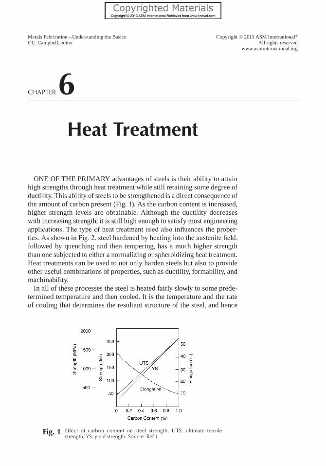
Copyright © 2013 ASM International®
All rights reservedwww.asminternational.org
Metals Fabrication—Understanding the BasicsF.C. Campbell, editor
Chapter 6Heat Treatment
One Of the primary advantages of steels is their ability to attain high strengths through heat treatment while still retaining some degree of ductility. this ability of steels to be strengthened is a direct consequence of the amount of carbon present (fig. 1). as the carbon content is increased, higher strength levels are obtainable. although the ductility decreases with increasing strength, it is still high enough to satisfy most engineering applications. The type of heat treatment used also influences the proper-ties. As shown in Fig. 2, steel hardened by heating into the austenite field, followed by quenching and then tempering, has a much higher strength than one subjected to either a normalizing or spheroidizing heat treatment. heat treatments can be used to not only harden steels but also to provide other useful combinations of properties, such as ductility, formability, and machinability.
in all of these processes the steel is heated fairly slowly to some prede-termined temperature and then cooled. it is the temperature and the rate of cooling that determines the resultant structure of the steel, and hence
Fig. 1 effect of carbon content on steel strength. UtS, ultimate tensile strength; YS, yield strength. Source: ref 1
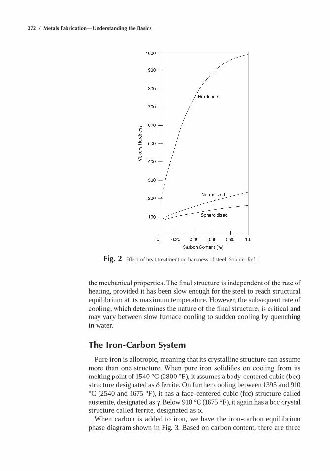
272 / Metals Fabrication—Understanding the Basics
the mechanical properties. The final structure is independent of the rate of heating, provided it has been slow enough for the steel to reach structural equilibrium at its maximum temperature. however, the subsequent rate of cooling, which determines the nature of the final structure, is critical and may vary between slow furnace cooling to sudden cooling by quenching in water.
The Iron-Carbon System
pure iron is allotropic, meaning that its crystalline structure can assume more than one structure. When pure iron solidifies on cooling from its melting point of 1540 °C (2800 °f), it assumes a body-centered cubic (bcc) structure designated as δ ferrite. On further cooling between 1395 and 910 °C (2540 and 1675 °f), it has a face-centered cubic (fcc) structure called austenite, designated as γ. Below 910 °C (1675 °f), it again has a bcc crystal structure called ferrite, designated as α.
When carbon is added to iron, we have the iron-carbon equilibrium phase diagram shown in fig. 3. Based on carbon content, there are three
Fig. 2 effect of heat treatment on hardness of steel. Source: ref 1
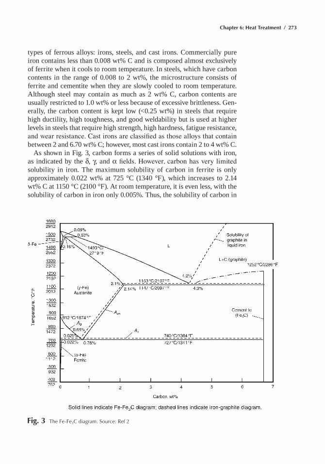
Chapter 6: Heat Treatment / 273
types of ferrous alloys: irons, steels, and cast irons. Commercially pure iron contains less than 0.008 wt% C and is composed almost exclusively of ferrite when it cools to room temperature. in steels, which have carbon contents in the range of 0.008 to 2 wt%, the microstructure consists of ferrite and cementite when they are slowly cooled to room temperature. although steel may contain as much as 2 wt% C, carbon contents are usually restricted to 1.0 wt% or less because of excessive brittleness. Gen-erally, the carbon content is kept low (<0.25 wt%) in steels that require high ductility, high toughness, and good weldability but is used at higher levels in steels that require high strength, high hardness, fatigue resistance, and wear resistance. Cast irons are classified as those alloys that contain between 2 and 6.70 wt% C; however, most cast irons contain 2 to 4 wt% C.
as shown in fig. 3, carbon forms a series of solid solutions with iron, as indicated by the δ, γ, and α fields. However, carbon has very limited solubility in iron. the maximum solubility of carbon in ferrite is only approximately 0.022 wt% at 725 °C (1340 °f), which increases to 2.14 wt% C at 1150 °C (2100 °f). at room temperature, it is even less, with the solubility of carbon in iron only 0.005%. thus, the solubility of carbon in
Fig. 3 the Fe-Fe3C diagram. Source: ref 2
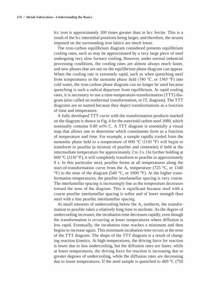
274 / Metals Fabrication—Understanding the Basics
fcc iron is approximately 100 times greater than in bcc ferrite. this is a result of the fcc interstitial positions being larger, and therefore, the strains imposed on the surrounding iron lattice are much lower.
the iron-carbon equilibrium diagram considered presents equilibrium cooling rates, such as may be approximated by a very large piece of steel undergoing very slow furnace cooling. however, under normal industrial processing conditions, the cooling rates are almost always much faster, and new phases that are not on the equilibrium phase diagram can appear. When the cooling rate is extremely rapid, such as when quenching steel from temperatures in the austenite phase field (740 °C, or 1365 °F) into cold water, the iron-carbon phase diagram can no longer be used because quenching is such a radical departure from equilibrium. at rapid cooling rates, it is necessary to use a time-temperature-transformation (ttt) dia-gram (also called an isothermal transformation, or it, diagram). the ttt diagrams are so named because they depict transformations as a function of time and temperature.
a fully developed ttt curve with the transformation products marked on the diagram is shown in fig. 4 for the eutectoid carbon steel 1080, which nominally contains 0.80 wt% C. a ttt diagram is essentially a visual map that allows one to determine which constituents form as a function of temperature and time. for example, a sample rapidly cooled from the austenitic phase field to a temperature of 600 °C (1110 °F) will begin to transform to pearlite (a mixture of pearlite and cementite) if held at the intermediate temperature for approximately 2 to 3 s. On further holding at 600 °C (1110 °f), it will completely transform to pearlite in approximately 9 s. in this particular steel, pearlite forms at all temperatures along the start-of-transformation curve from the a1 temperature (725 °C, or 1340 °f) to the nose of the diagram (540 °C, or 1000 °f). at the higher trans-formation temperatures, the pearlite interlamellar spacing is very coarse. The interlamellar spacing is increasingly fine as the temperature decreases toward the nose of the diagram. This is significant because steel with a coarse pearlite interlamellar spacing is softer and of lower strength than steel with a fine pearlite interlamellar spacing.
at small amounts of undercooling below the a1 isotherm, the transfor-mation to pearlite takes a relatively long time to nucleate. as the degree of undercooling increases, the incubation time decreases rapidly, even though the transformation is occurring at lower temperatures where diffusion is less rapid. eventually, the incubation time reaches a minimum and then begins to increase again. this minimum incubation time occurs at the nose of the ttt diagram. the shape of the ttt diagram is a result of chang-ing reaction kinetics. at high temperatures, the driving force for reaction is lower due to less undercooling, but the diffusion rates are faster, while at lower temperatures, the driving force for reaction is increasing due to greater degrees of undercooling, while the diffusion rates are decreasing due to lower temperatures. if the steel sample is quenched to 400 °C (750
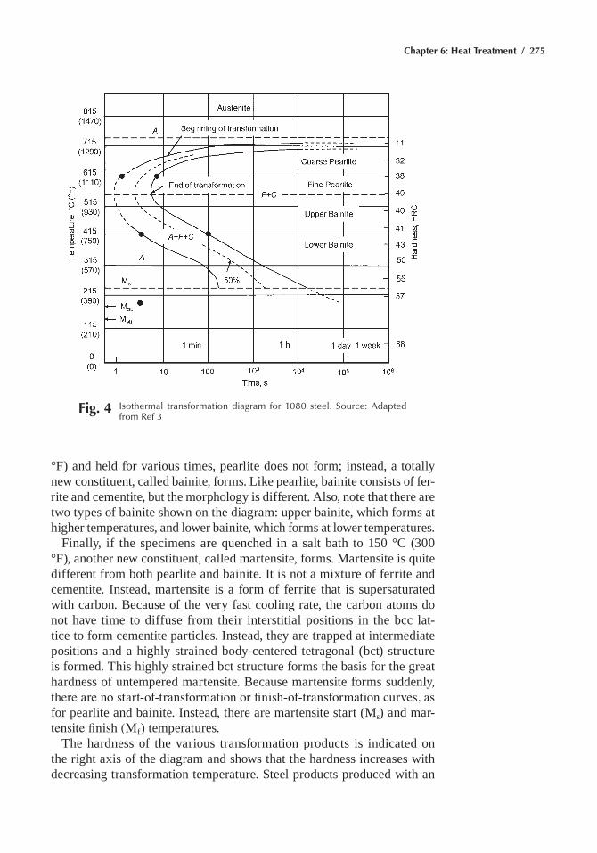
Chapter 6: Heat Treatment / 275
°f) and held for various times, pearlite does not form; instead, a totally new constituent, called bainite, forms. Like pearlite, bainite consists of fer-rite and cementite, but the morphology is different. also, note that there are two types of bainite shown on the diagram: upper bainite, which forms at higher temperatures, and lower bainite, which forms at lower temperatures.
finally, if the specimens are quenched in a salt bath to 150 °C (300 °f), another new constituent, called martensite, forms. martensite is quite different from both pearlite and bainite. it is not a mixture of ferrite and cementite. instead, martensite is a form of ferrite that is supersaturated with carbon. Because of the very fast cooling rate, the carbon atoms do not have time to diffuse from their interstitial positions in the bcc lat-tice to form cementite particles. instead, they are trapped at intermediate positions and a highly strained body-centered tetragonal (bct) structure is formed. this highly strained bct structure forms the basis for the great hardness of untempered martensite. Because martensite forms suddenly, there are no start-of-transformation or finish-of-transformation curves, as for pearlite and bainite. instead, there are martensite start (ms) and mar-tensite finish (Mf) temperatures.
the hardness of the various transformation products is indicated on the right axis of the diagram and shows that the hardness increases with decreasing transformation temperature. Steel products produced with an
Fig. 4 Isothermal transformation diagram for 1080 steel. Source: adapted from ref 3
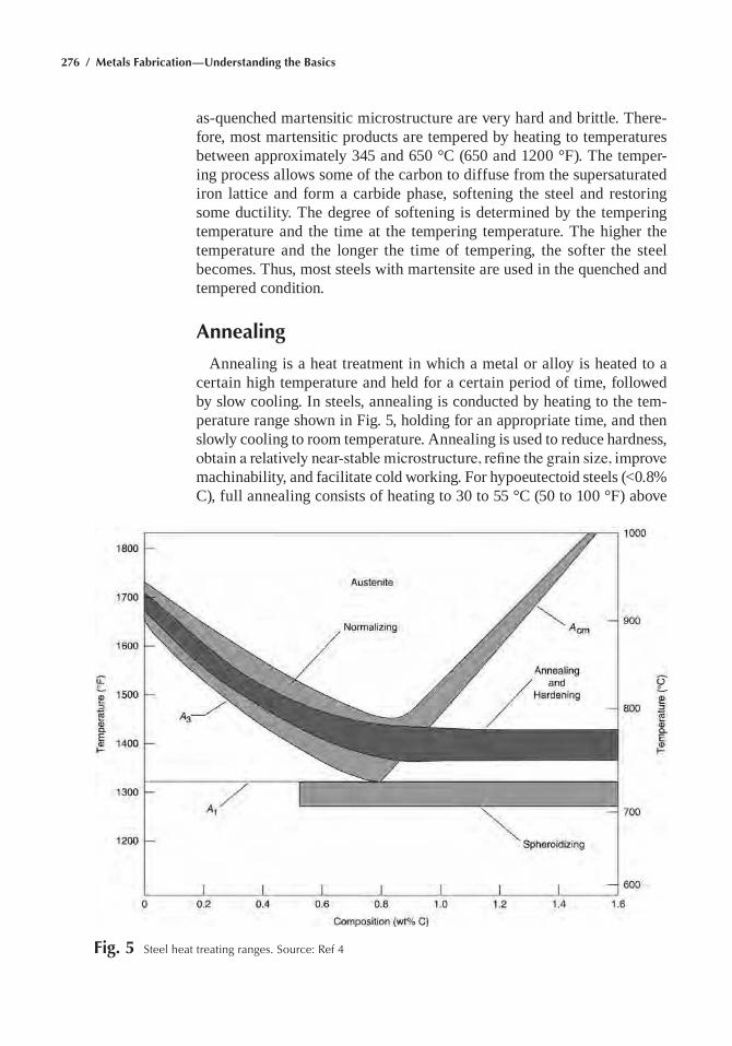
276 / Metals Fabrication—Understanding the Basics
as-quenched martensitic microstructure are very hard and brittle. there-fore, most martensitic products are tempered by heating to temperatures between approximately 345 and 650 °C (650 and 1200 °f). the temper-ing process allows some of the carbon to diffuse from the supersaturated iron lattice and form a carbide phase, softening the steel and restoring some ductility. the degree of softening is determined by the tempering temperature and the time at the tempering temperature. the higher the temperature and the longer the time of tempering, the softer the steel becomes. thus, most steels with martensite are used in the quenched and tempered condition.
Annealing
annealing is a heat treatment in which a metal or alloy is heated to a certain high temperature and held for a certain period of time, followed by slow cooling. in steels, annealing is conducted by heating to the tem-perature range shown in fig. 5, holding for an appropriate time, and then slowly cooling to room temperature. annealing is used to reduce hardness, obtain a relatively near-stable microstructure, refine the grain size, improve machinability, and facilitate cold working. for hypoeutectoid steels (<0.8% C), full annealing consists of heating to 30 to 55 °C (50 to 100 °f) above
Fig. 5 Steel heat treating ranges. Source: ref 4
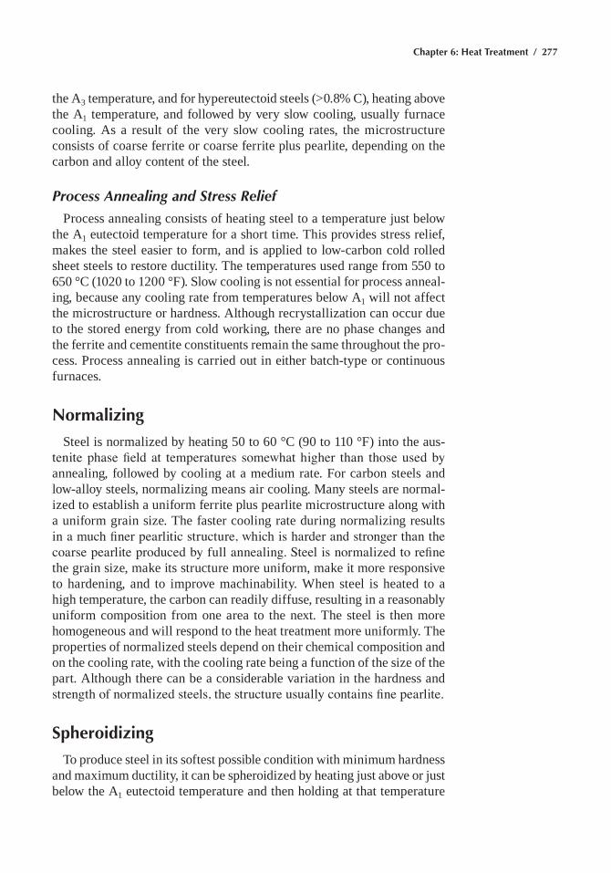
Chapter 6: Heat Treatment / 277
the a3 temperature, and for hypereutectoid steels (>0.8% C), heating above the a1 temperature, and followed by very slow cooling, usually furnace cooling. as a result of the very slow cooling rates, the microstructure consists of coarse ferrite or coarse ferrite plus pearlite, depending on the carbon and alloy content of the steel.
Process Annealing and Stress Relief
process annealing consists of heating steel to a temperature just below the a1 eutectoid temperature for a short time. this provides stress relief, makes the steel easier to form, and is applied to low-carbon cold rolled sheet steels to restore ductility. the temperatures used range from 550 to 650 °C (1020 to 1200 °f). Slow cooling is not essential for process anneal-ing, because any cooling rate from temperatures below a1 will not affect the microstructure or hardness. although recrystallization can occur due to the stored energy from cold working, there are no phase changes and the ferrite and cementite constituents remain the same throughout the pro-cess. process annealing is carried out in either batch-type or continuous furnaces.
Normalizing
Steel is normalized by heating 50 to 60 °C (90 to 110 °f) into the aus-tenite phase field at temperatures somewhat higher than those used by annealing, followed by cooling at a medium rate. for carbon steels and low-alloy steels, normalizing means air cooling. many steels are normal-ized to establish a uniform ferrite plus pearlite microstructure along with a uniform grain size. the faster cooling rate during normalizing results in a much finer pearlitic structure, which is harder and stronger than the coarse pearlite produced by full annealing. Steel is normalized to refine the grain size, make its structure more uniform, make it more responsive to hardening, and to improve machinability. When steel is heated to a high temperature, the carbon can readily diffuse, resulting in a reasonably uniform composition from one area to the next. the steel is then more homogeneous and will respond to the heat treatment more uniformly. the properties of normalized steels depend on their chemical composition and on the cooling rate, with the cooling rate being a function of the size of the part. although there can be a considerable variation in the hardness and strength of normalized steels, the structure usually contains fine pearlite.
Spheroidizing
to produce steel in its softest possible condition with minimum hardness and maximum ductility, it can be spheroidized by heating just above or just below the a1 eutectoid temperature and then holding at that temperature
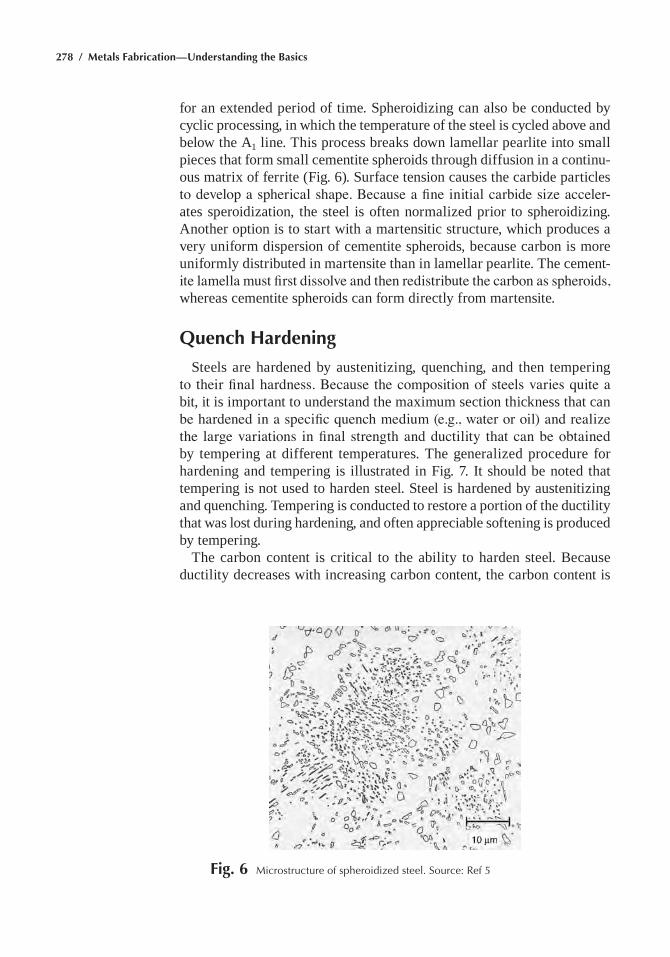
278 / Metals Fabrication—Understanding the Basics
for an extended period of time. Spheroidizing can also be conducted by cyclic processing, in which the temperature of the steel is cycled above and below the a1 line. this process breaks down lamellar pearlite into small pieces that form small cementite spheroids through diffusion in a continu-ous matrix of ferrite (fig. 6). Surface tension causes the carbide particles to develop a spherical shape. Because a fine initial carbide size acceler-ates speroidization, the steel is often normalized prior to spheroidizing. another option is to start with a martensitic structure, which produces a very uniform dispersion of cementite spheroids, because carbon is more uniformly distributed in martensite than in lamellar pearlite. the cement-ite lamella must first dissolve and then redistribute the carbon as spheroids, whereas cementite spheroids can form directly from martensite.
Quench Hardening
Steels are hardened by austenitizing, quenching, and then tempering to their final hardness. Because the composition of steels varies quite a bit, it is important to understand the maximum section thickness that can be hardened in a specific quench medium (e.g., water or oil) and realize the large variations in final strength and ductility that can be obtained by tempering at different temperatures. the generalized procedure for hardening and tempering is illustrated in fig. 7. it should be noted that tempering is not used to harden steel. Steel is hardened by austenitizing and quenching. tempering is conducted to restore a portion of the ductility that was lost during hardening, and often appreciable softening is produced by tempering.
the carbon content is critical to the ability to harden steel. Because ductility decreases with increasing carbon content, the carbon content is
Fig. 6 Microstructure of spheroidized steel. Source: ref 5
Chapter 6: Heat Treatment / 279
held to approximately 0.45% in many engineering steels. however, when wear resistance is required, for example in tool and die steels, it may be increased to over 1.0%. the addition of alloying elements shifts the nose of the ttt diagram to the right, thus allowing thicker sections to be hardened or allowing less drastic quenches. the effects of alloying elements and section size on hardenability are illustrated in fig. 8. in this example, the 1040 and 4140 steels both contain nominal carbon contents of 0.40%, and yet due to the alloying elements in 4140, 4140 hardens to a much greater depth. however, as the diameter of a bar of 4140 is increased from 5 to 10 cm (2 to 4 in.), the depth of hardening decreases. Some more highly alloyed steels have the ttt diagram shifted so far to the right that they will form fully martensitic structures in fairly thick sections by simply air cooling to room temperature. therefore, while some alloying elements may not directly increase the hardness of martensite significantly, they do increase the hardenability, which is the depth of the martensite microstructure that can be produced in steel of a given carbon content during quenching.
Continuous Cooling Transformation Diagrams
time-temperature-transformation diagrams provide valuable informa-tion about the kinetics of the transformation of austenite and are useful tools for developing heat treatments. however, in practical heat treatments, where the size of the part being treated is usually significant, the tem-perature and the rate of change of temperature vary with position within the part being heat treated. also, there are heat treatments in which the steel is continuously cooled. therefore, for industrial applications, continu-ous cooling transformation (CCt) diagrams are more useful than ttt
Fig. 7 hardening heat treatment for steels. Source: ref 1
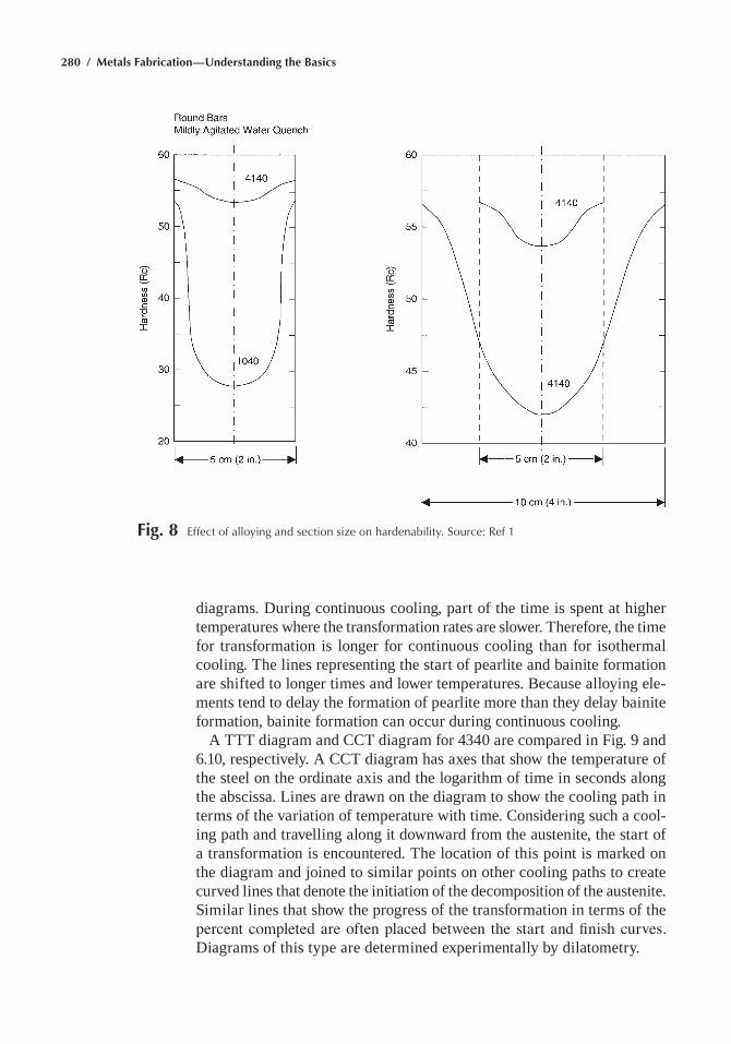
280 / Metals Fabrication—Understanding the Basics
Fig. 8 effect of alloying and section size on hardenability. Source: ref 1
diagrams. During continuous cooling, part of the time is spent at higher temperatures where the transformation rates are slower. therefore, the time for transformation is longer for continuous cooling than for isothermal cooling. the lines representing the start of pearlite and bainite formation are shifted to longer times and lower temperatures. Because alloying ele-ments tend to delay the formation of pearlite more than they delay bainite formation, bainite formation can occur during continuous cooling.
a ttt diagram and CCt diagram for 4340 are compared in fig. 9 and 6.10, respectively. a CCt diagram has axes that show the temperature of the steel on the ordinate axis and the logarithm of time in seconds along the abscissa. Lines are drawn on the diagram to show the cooling path in terms of the variation of temperature with time. Considering such a cool-ing path and travelling along it downward from the austenite, the start of a transformation is encountered. the location of this point is marked on the diagram and joined to similar points on other cooling paths to create curved lines that denote the initiation of the decomposition of the austenite. Similar lines that show the progress of the transformation in terms of the percent completed are often placed between the start and finish curves. Diagrams of this type are determined experimentally by dilatometry.
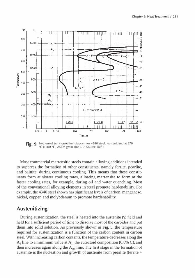
Chapter 6: Heat Treatment / 281
Fig. 9 Isothermal transformation diagram for 4340 steel. austenitized at 870 °C (1600 °F), aStM grain size 6–7. Source: ref 6
most commercial martensitic steels contain alloying additions intended to suppress the formation of other constituents, namely ferrite, pearlite, and bainite, during continuous cooling. this means that these constit-uents form at slower cooling rates, allowing martensite to form at the faster cooling rates, for example, during oil and water quenching. most of the conventional alloying elements in steel promote hardenability. for example, the 4340 steel shown has significant levels of carbon, manganese, nickel, copper, and molybdenum to promote hardenability.
Austenitizing
During austenitization, the steel is heated into the austenite (γ) field and held for a sufficient period of time to dissolve most of the carbides and put them into solid solution. as previously shown in fig. 5, the temperature required for austenitization is a function of the carbon content in carbon steel. With increasing carbon contents, the temperature decreases along the a3 line to a minimum value at a1, the eutectoid composition (0.8% C), and then increases again along the acm line. The first stage in the formation of austenite is the nucleation and growth of austenite from pearlite (ferrite +
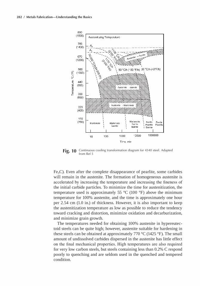
282 / Metals Fabrication—Understanding the Basics
fe3C). even after the complete disappearance of pearlite, some carbides will remain in the austenite. the formation of homogeneous austenite is accelerated by increasing the temperature and increasing the fineness of the initial carbide particles. to minimize the time for austenitization, the temperature used is approximately 55 °C (100 °f) above the minimum temperature for 100% austenite, and the time is approximately one hour per 2.54 cm (1.0 in.) of thickness. however, it is also important to keep the austenitization temperature as low as possible to reduce the tendency toward cracking and distortion, minimize oxidation and decarburization, and minimize grain growth.
the temperatures needed for obtaining 100% austenite in hypereutec-toid steels can be quite high; however, austenite suitable for hardening in these steels can be obtained at approximately 770 °C (1425 °f). the small amount of undissolved carbides dispersed in the austenite has little effect on the final mechanical properties. High temperatures are also required for very low carbon steels, but steels containing less than 0.2% C respond poorly to quenching and are seldom used in the quenched and tempered condition.
Fig. 10 Continuous cooling transformation diagram for 4340 steel. adapted from ref 5
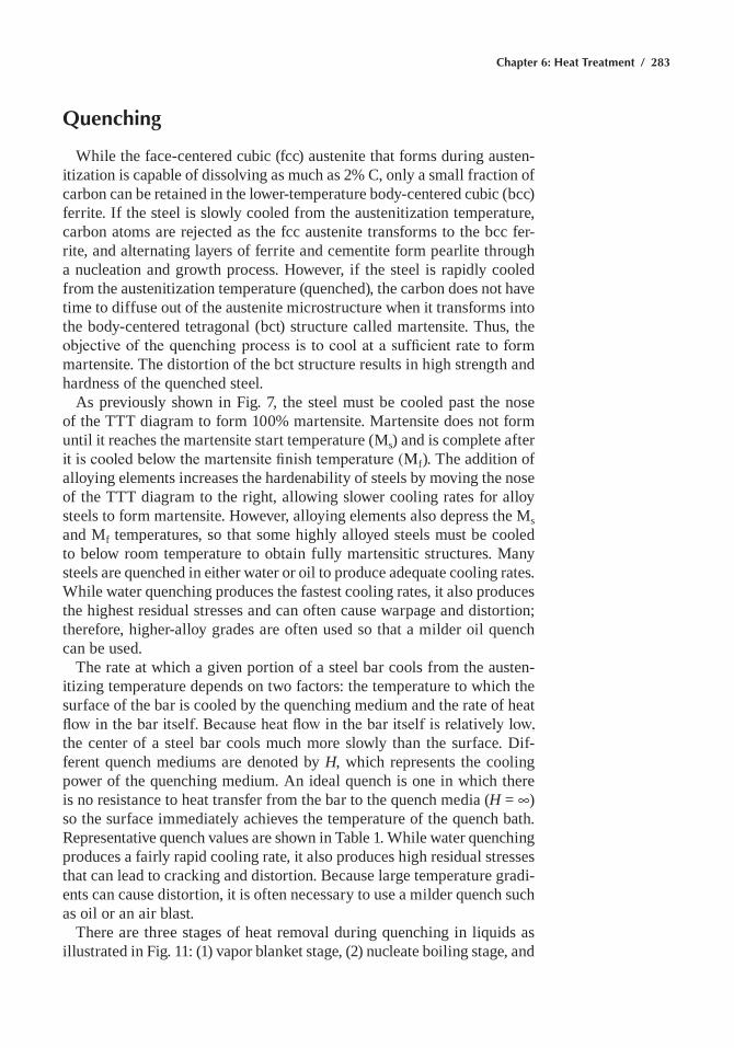
Chapter 6: Heat Treatment / 283
Quenching
While the face-centered cubic (fcc) austenite that forms during austen-itization is capable of dissolving as much as 2% C, only a small fraction of carbon can be retained in the lower-temperature body-centered cubic (bcc) ferrite. if the steel is slowly cooled from the austenitization temperature, carbon atoms are rejected as the fcc austenite transforms to the bcc fer-rite, and alternating layers of ferrite and cementite form pearlite through a nucleation and growth process. however, if the steel is rapidly cooled from the austenitization temperature (quenched), the carbon does not have time to diffuse out of the austenite microstructure when it transforms into the body-centered tetragonal (bct) structure called martensite. thus, the objective of the quenching process is to cool at a sufficient rate to form martensite. the distortion of the bct structure results in high strength and hardness of the quenched steel.
as previously shown in fig. 7, the steel must be cooled past the nose of the ttt diagram to form 100% martensite. martensite does not form until it reaches the martensite start temperature (ms) and is complete after it is cooled below the martensite finish temperature (Mf). the addition of alloying elements increases the hardenability of steels by moving the nose of the ttt diagram to the right, allowing slower cooling rates for alloy steels to form martensite. however, alloying elements also depress the ms and mf temperatures, so that some highly alloyed steels must be cooled to below room temperature to obtain fully martensitic structures. many steels are quenched in either water or oil to produce adequate cooling rates. While water quenching produces the fastest cooling rates, it also produces the highest residual stresses and can often cause warpage and distortion; therefore, higher-alloy grades are often used so that a milder oil quench can be used.
the rate at which a given portion of a steel bar cools from the austen-itizing temperature depends on two factors: the temperature to which the surface of the bar is cooled by the quenching medium and the rate of heat flow in the bar itself. Because heat flow in the bar itself is relatively low, the center of a steel bar cools much more slowly than the surface. Dif-ferent quench mediums are denoted by H, which represents the cooling power of the quenching medium. an ideal quench is one in which there is no resistance to heat transfer from the bar to the quench media (H = •) so the surface immediately achieves the temperature of the quench bath. representative quench values are shown in table 1. While water quenching produces a fairly rapid cooling rate, it also produces high residual stresses that can lead to cracking and distortion. Because large temperature gradi-ents can cause distortion, it is often necessary to use a milder quench such as oil or an air blast.
there are three stages of heat removal during quenching in liquids as illustrated in fig. 11: (1) vapor blanket stage, (2) nucleate boiling stage, and
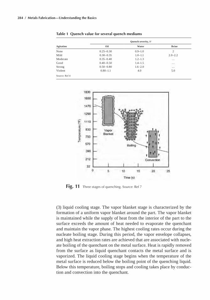
284 / Metals Fabrication—Understanding the Basics
(3) liquid cooling stage. the vapor blanket stage is characterized by the formation of a uniform vapor blanket around the part. the vapor blanket is maintained while the supply of heat from the interior of the part to the surface exceeds the amount of heat needed to evaporate the quenchant and maintain the vapor phase. the highest cooling rates occur during the nucleate boiling stage. During this period, the vapor envelope collapses, and high heat extraction rates are achieved that are associated with nucle-ate boiling of the quenchant on the metal surface. heat is rapidly removed from the surface as liquid quenchant contacts the metal surface and is vaporized. the liquid cooling stage begins when the temperature of the metal surface is reduced below the boiling point of the quenching liquid. Below this temperature, boiling stops and cooling takes place by conduc-tion and convection into the quenchant.
Table 1 Quench value for several quench mediums
Agitation
Quench severity, H
Oil Water Brine
none 0.25–0.30 0.9–1.0 2mild 0.30–0.35 1.0–1.1 2.0–2.2moderate 0.35–0.40 1.2–1.3 …Good 0.40–0.50 1.4–1.5 …Strong 0.50–0.80 1.6–2.0 …Violent 0.80–1.1 4.0 5.0
Source: ref 4
Fig. 11 three stages of quenching. Source: ref 7
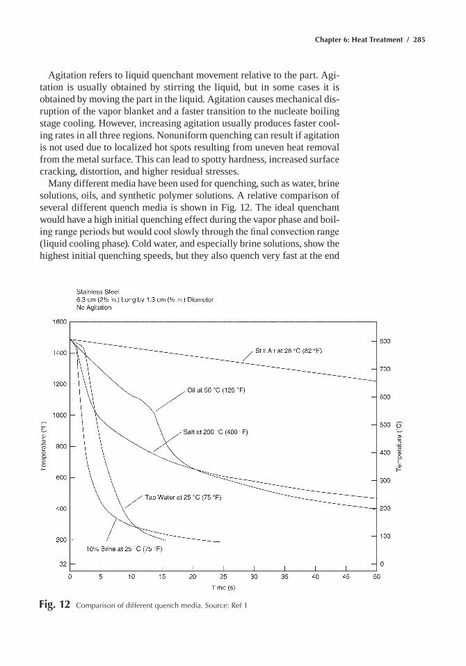
Chapter 6: Heat Treatment / 285
agitation refers to liquid quenchant movement relative to the part. agi-tation is usually obtained by stirring the liquid, but in some cases it is obtained by moving the part in the liquid. agitation causes mechanical dis-ruption of the vapor blanket and a faster transition to the nucleate boiling stage cooling. however, increasing agitation usually produces faster cool-ing rates in all three regions. nonuniform quenching can result if agitation is not used due to localized hot spots resulting from uneven heat removal from the metal surface. this can lead to spotty hardness, increased surface cracking, distortion, and higher residual stresses.
many different media have been used for quenching, such as water, brine solutions, oils, and synthetic polymer solutions. a relative comparison of several different quench media is shown in fig. 12. the ideal quenchant would have a high initial quenching effect during the vapor phase and boil-ing range periods but would cool slowly through the final convection range (liquid cooling phase). Cold water, and especially brine solutions, show the highest initial quenching speeds, but they also quench very fast at the end
Fig. 12 Comparison of different quench media. Source: ref 1
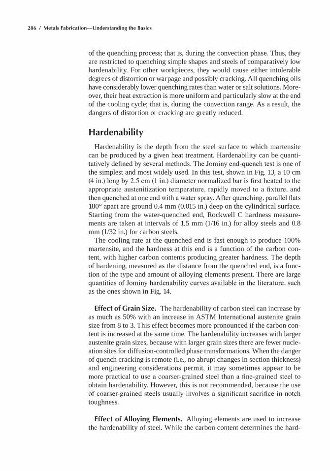
286 / Metals Fabrication—Understanding the Basics
of the quenching process; that is, during the convection phase. thus, they are restricted to quenching simple shapes and steels of comparatively low hardenability. for other workpieces, they would cause either intolerable degrees of distortion or warpage and possibly cracking. all quenching oils have considerably lower quenching rates than water or salt solutions. more-over, their heat extraction is more uniform and particularly slow at the end of the cooling cycle; that is, during the convection range. as a result, the dangers of distortion or cracking are greatly reduced.
Hardenability
hardenability is the depth from the steel surface to which martensite can be produced by a given heat treatment. hardenability can be quanti-tatively defined by several methods. The Jominy end-quench test is one of the simplest and most widely used. in this test, shown in fig. 13, a 10 cm (4 in.) long by 2.5 cm (1 in.) diameter normalized bar is first heated to the appropriate austenitization temperature, rapidly moved to a fixture, and then quenched at one end with a water spray. After quenching, parallel flats 180° apart are ground 0.4 mm (0.015 in.) deep on the cylindrical surface. Starting from the water-quenched end, rockwell C hardness measure-ments are taken at intervals of 1.5 mm (1/16 in.) for alloy steels and 0.8 mm (1/32 in.) for carbon steels.
the cooling rate at the quenched end is fast enough to produce 100% martensite, and the hardness at this end is a function of the carbon con-tent, with higher carbon contents producing greater hardness. the depth of hardening, measured as the distance from the quenched end, is a func-tion of the type and amount of alloying elements present. there are large quantities of Jominy hardenability curves available in the literature, such as the ones shown in fig. 14.
Effect of Grain Size. the hardenability of carbon steel can increase by as much as 50% with an increase in aStm international austenite grain size from 8 to 3. this effect becomes more pronounced if the carbon con-tent is increased at the same time. the hardenability increases with larger austenite grain sizes, because with larger grain sizes there are fewer nucle-ation sites for diffusion-controlled phase transformations. When the danger of quench cracking is remote (i.e., no abrupt changes in section thickness) and engineering considerations permit, it may sometimes appear to be more practical to use a coarser-grained steel than a fine-grained steel to obtain hardenability. however, this is not recommended, because the use of coarser-grained steels usually involves a significant sacrifice in notch toughness.
Effect of Alloying Elements. alloying elements are used to increase the hardenability of steel. While the carbon content determines the hard-
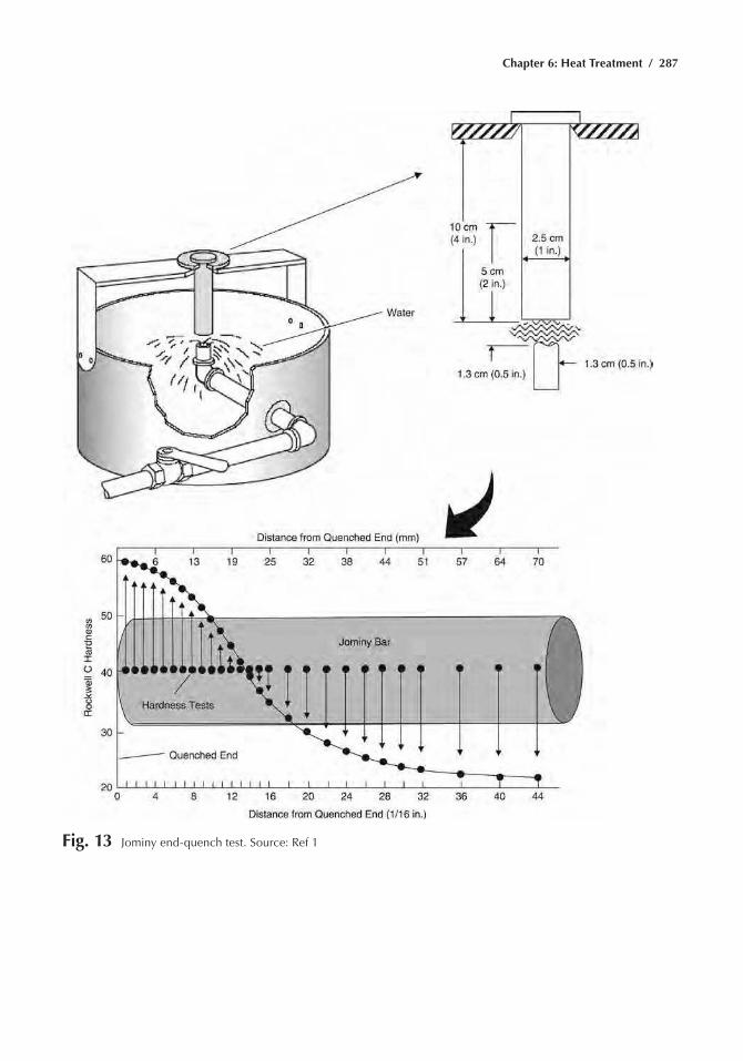
Chapter 6: Heat Treatment / 287
Fig. 13 Jominy end-quench test. Source: ref 1
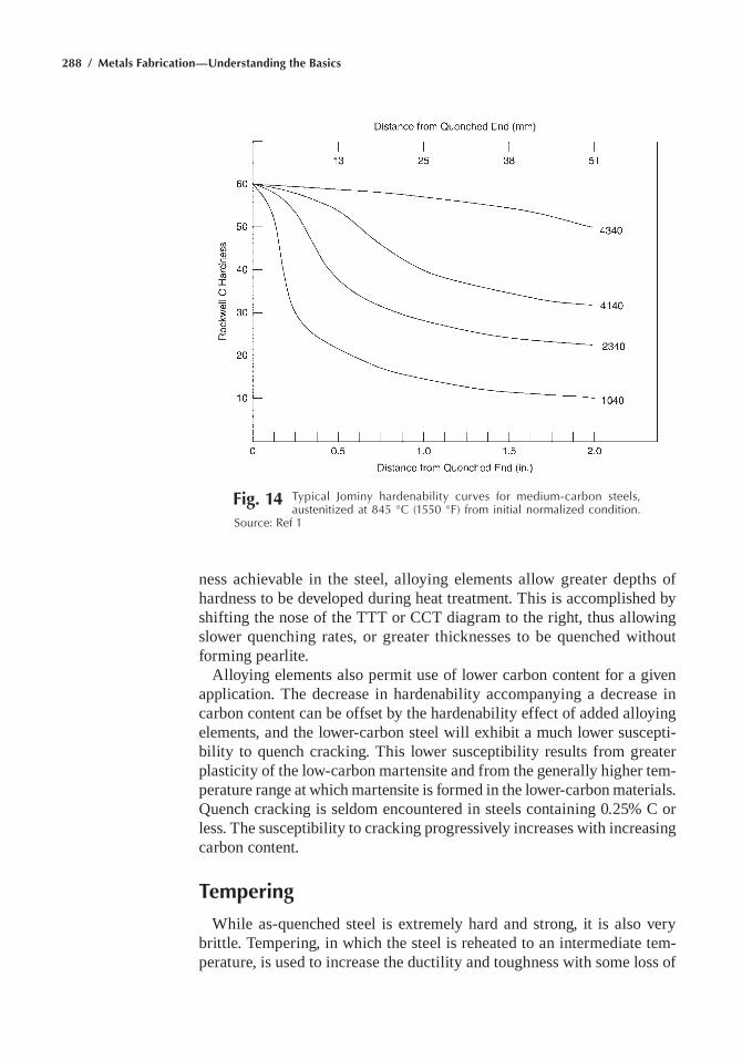
288 / Metals Fabrication—Understanding the Basics
ness achievable in the steel, alloying elements allow greater depths of hardness to be developed during heat treatment. this is accomplished by shifting the nose of the ttt or CCt diagram to the right, thus allowing slower quenching rates, or greater thicknesses to be quenched without forming pearlite.
alloying elements also permit use of lower carbon content for a given application. the decrease in hardenability accompanying a decrease in carbon content can be offset by the hardenability effect of added alloying elements, and the lower-carbon steel will exhibit a much lower suscepti-bility to quench cracking. this lower susceptibility results from greater plasticity of the low-carbon martensite and from the generally higher tem-perature range at which martensite is formed in the lower-carbon materials. Quench cracking is seldom encountered in steels containing 0.25% C or less. the susceptibility to cracking progressively increases with increasing carbon content.
Tempering
While as-quenched steel is extremely hard and strong, it is also very brittle. tempering, in which the steel is reheated to an intermediate tem-perature, is used to increase the ductility and toughness with some loss of
Fig. 14 typical Jominy hardenability curves for medium-carbon steels, austenitized at 845 °C (1550 °F) from initial normalized condition.
Source: ref 1
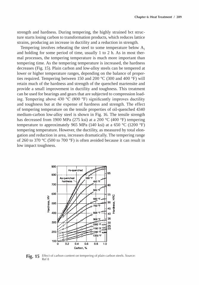
Chapter 6: Heat Treatment / 289
strength and hardness. During tempering, the highly strained bct struc-ture starts losing carbon to transformation products, which reduces lattice strains, producing an increase in ductility and a reduction in strength.
tempering involves reheating the steel to some temperature below a1 and holding for some period of time, usually 1 to 2 h. as in most ther-mal processes, the tempering temperature is much more important than tempering time. as the tempering temperature is increased, the hardness decreases (fig. 15). plain carbon and low-alloy steels can be tempered at lower or higher temperature ranges, depending on the balance of proper-ties required. tempering between 150 and 200 °C (300 and 400 °f) will retain much of the hardness and strength of the quenched martensite and provide a small improvement in ductility and toughness. this treatment can be used for bearings and gears that are subjected to compression load-ing. Tempering above 430 °C (800 °F) significantly improves ductility and toughness but at the expense of hardness and strength. the effect of tempering temperature on the tensile properties of oil-quenched 4340 medium-carbon low-alloy steel is shown in fig. 16. the tensile strength has decreased from 1900 mpa (275 ksi) at a 200 °C (400 °f) tempering temperature to approximately 965 mpa (140 ksi) at a 650 °C (1200 °f) tempering temperature. however, the ductility, as measured by total elon-gation and reduction in area, increases dramatically. the tempering range of 260 to 370 °C (500 to 700 °f) is often avoided because it can result in low impact toughness.
Fig. 15 effect of carbon content on tempering of plain carbon steels. Source: ref 8
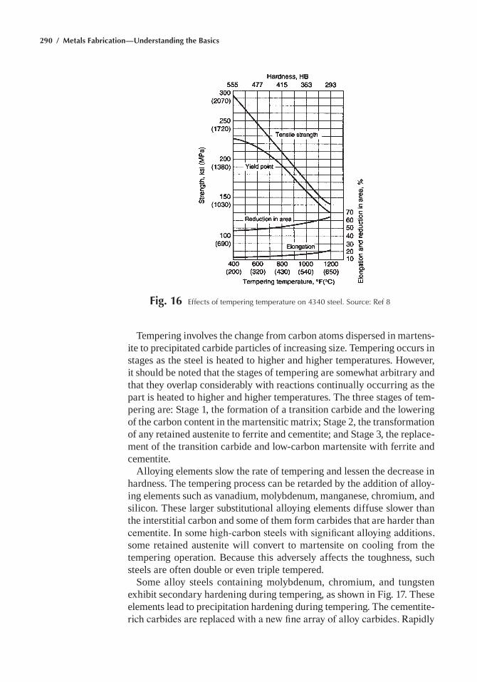
290 / Metals Fabrication—Understanding the Basics
tempering involves the change from carbon atoms dispersed in martens-ite to precipitated carbide particles of increasing size. tempering occurs in stages as the steel is heated to higher and higher temperatures. however, it should be noted that the stages of tempering are somewhat arbitrary and that they overlap considerably with reactions continually occurring as the part is heated to higher and higher temperatures. the three stages of tem-pering are: Stage 1, the formation of a transition carbide and the lowering of the carbon content in the martensitic matrix; Stage 2, the transformation of any retained austenite to ferrite and cementite; and Stage 3, the replace-ment of the transition carbide and low-carbon martensite with ferrite and cementite.
alloying elements slow the rate of tempering and lessen the decrease in hardness. the tempering process can be retarded by the addition of alloy-ing elements such as vanadium, molybdenum, manganese, chromium, and silicon. these larger substitutional alloying elements diffuse slower than the interstitial carbon and some of them form carbides that are harder than cementite. In some high-carbon steels with significant alloying additions, some retained austenite will convert to martensite on cooling from the tempering operation. Because this adversely affects the toughness, such steels are often double or even triple tempered.
Some alloy steels containing molybdenum, chromium, and tungsten exhibit secondary hardening during tempering, as shown in fig. 17. these elements lead to precipitation hardening during tempering. the cementite-rich carbides are replaced with a new fine array of alloy carbides. Rapidly
Fig. 16 effects of tempering temperature on 4340 steel. Source: ref 8
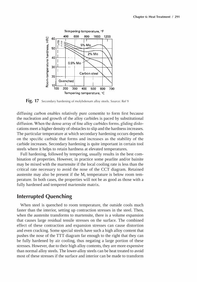
Chapter 6: Heat Treatment / 291
diffusing carbon enables relatively pure cementite to form first because the nucleation and growth of the alloy carbides is paced by substitutional diffusion. When the dense array of fine alloy carbides forms, gliding dislo-cations meet a higher density of obstacles to slip and the hardness increases. the particular temperature at which secondary hardening occurs depends on the specific carbide that forms and increases as the stability of the carbide increases. Secondary hardening is quite important in certain tool steels where it helps to retain hardness at elevated temperatures.
full hardening, followed by tempering, usually results in the best com-bination of properties. however, in practice some pearlite and/or bainite may be mixed with the martensite if the local cooling rate is less than the critical rate necessary to avoid the nose of the CCt diagram. retained austenite may also be present if the mf temperature is below room tem-perature. in both cases, the properties will not be as good as those with a fully hardened and tempered martensite matrix.
Interrupted Quenching
When steel is quenched to room temperature, the outside cools much faster than the interior, setting up contraction stresses in the steel. then, when the austenite transforms to martensite, there is a volume expansion that causes large residual tensile stresses on the surface. the combined effect of these contraction and expansion stresses can cause distortion and even cracking. Some special steels have such a high alloy content that pushes the nose of the ttt diagram far enough to the right that they can be fully hardened by air cooling, thus negating a large portion of these stresses. however, due to their high alloy contents, they are more expensive than normal alloy steels. the lower-alloy steels can be heat treated to avoid most of these stresses if the surface and interior can be made to transform
Fig. 17 Secondary hardening of molybdenum alloy steels. Source: ref 9
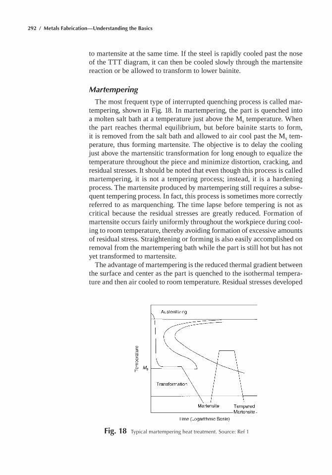
292 / Metals Fabrication—Understanding the Basics
to martensite at the same time. if the steel is rapidly cooled past the nose of the ttt diagram, it can then be cooled slowly through the martensite reaction or be allowed to transform to lower bainite.
Martempering
the most frequent type of interrupted quenching process is called mar-tempering, shown in fig. 18. in martempering, the part is quenched into a molten salt bath at a temperature just above the ms temperature. When the part reaches thermal equilibrium, but before bainite starts to form, it is removed from the salt bath and allowed to air cool past the ms tem-perature, thus forming martensite. the objective is to delay the cooling just above the martensitic transformation for long enough to equalize the temperature throughout the piece and minimize distortion, cracking, and residual stresses. it should be noted that even though this process is called martempering, it is not a tempering process; instead, it is a hardening process. the martensite produced by martempering still requires a subse-quent tempering process. in fact, this process is sometimes more correctly referred to as marquenching. the time lapse before tempering is not as critical because the residual stresses are greatly reduced. formation of martensite occurs fairly uniformly throughout the workpiece during cool-ing to room temperature, thereby avoiding formation of excessive amounts of residual stress. Straightening or forming is also easily accomplished on removal from the martempering bath while the part is still hot but has not yet transformed to martensite.
the advantage of martempering is the reduced thermal gradient between the surface and center as the part is quenched to the isothermal tempera-ture and then air cooled to room temperature. residual stresses developed
Fig. 18 typical martempering heat treatment. Source: ref 1
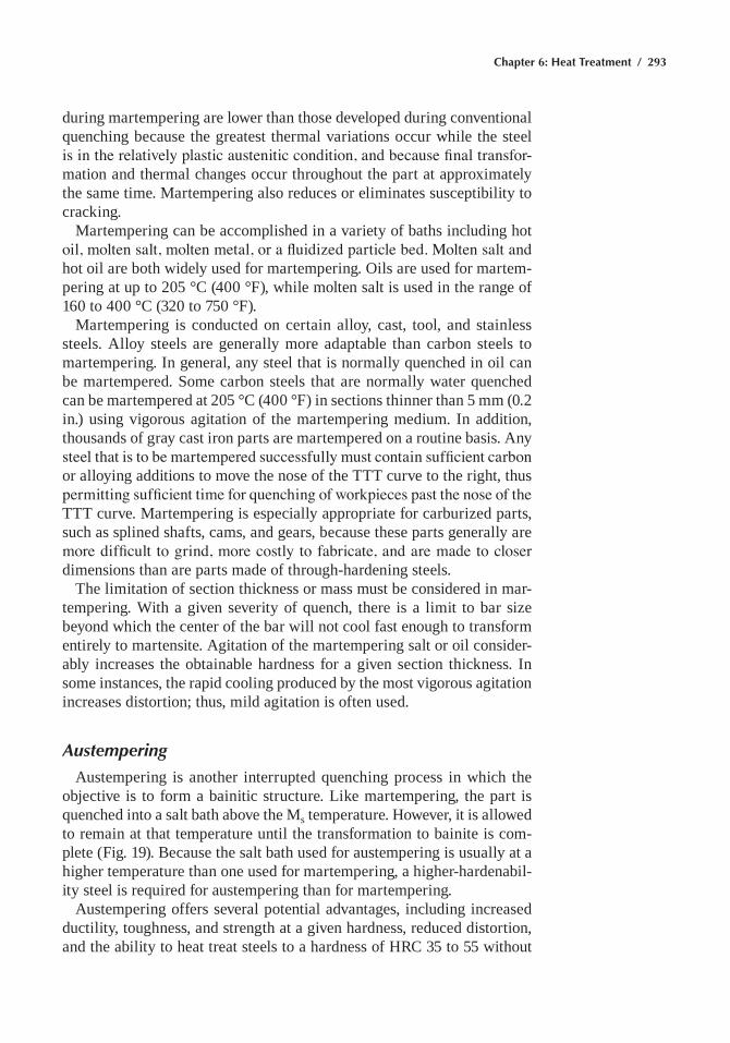
Chapter 6: Heat Treatment / 293
during martempering are lower than those developed during conventional quenching because the greatest thermal variations occur while the steel is in the relatively plastic austenitic condition, and because final transfor-mation and thermal changes occur throughout the part at approximately the same time. martempering also reduces or eliminates susceptibility to cracking.
martempering can be accomplished in a variety of baths including hot oil, molten salt, molten metal, or a fluidized particle bed. Molten salt and hot oil are both widely used for martempering. Oils are used for martem-pering at up to 205 °C (400 °f), while molten salt is used in the range of 160 to 400 °C (320 to 750 °f).
martempering is conducted on certain alloy, cast, tool, and stainless steels. alloy steels are generally more adaptable than carbon steels to martempering. in general, any steel that is normally quenched in oil can be martempered. Some carbon steels that are normally water quenched can be martempered at 205 °C (400 °f) in sections thinner than 5 mm (0.2 in.) using vigorous agitation of the martempering medium. in addition, thousands of gray cast iron parts are martempered on a routine basis. any steel that is to be martempered successfully must contain sufficient carbon or alloying additions to move the nose of the ttt curve to the right, thus permitting sufficient time for quenching of workpieces past the nose of the ttt curve. martempering is especially appropriate for carburized parts, such as splined shafts, cams, and gears, because these parts generally are more difficult to grind, more costly to fabricate, and are made to closer dimensions than are parts made of through-hardening steels.
the limitation of section thickness or mass must be considered in mar-tempering. With a given severity of quench, there is a limit to bar size beyond which the center of the bar will not cool fast enough to transform entirely to martensite. agitation of the martempering salt or oil consider-ably increases the obtainable hardness for a given section thickness. in some instances, the rapid cooling produced by the most vigorous agitation increases distortion; thus, mild agitation is often used.
Austempering
austempering is another interrupted quenching process in which the objective is to form a bainitic structure. Like martempering, the part is quenched into a salt bath above the ms temperature. however, it is allowed to remain at that temperature until the transformation to bainite is com-plete (fig. 19). Because the salt bath used for austempering is usually at a higher temperature than one used for martempering, a higher-hardenabil-ity steel is required for austempering than for martempering.
austempering offers several potential advantages, including increased ductility, toughness, and strength at a given hardness, reduced distortion, and the ability to heat treat steels to a hardness of hrC 35 to 55 without
294 / Metals Fabrication—Understanding the Basics
having to temper. One of the outstanding attributes of austempered steels is their high impact resistance. for example, an austempered steel heat treated to the same hardness as a quenched and tempered steel might have a Charpy V-notch impact energy of 54 J (40 ft·lbf) compared to only 20 J (15 ft·lbf) for a conventionally hardened steel. Because austempering is an interrupted quenching process that produces bainite rather than martens-ite, parts can usually be produced with less dimensional change than by conventional quenching and tempering. in addition, austempered parts do not normally require a tempering operation.
a typical austempering cycle would be to heat to a temperature within the austenitizing range (790 to 910 °C, or 1450 to 1675 °f), quench in a salt bath maintained at a constant temperature, usually in the range 260 to 400 °C (500 to 750 °f), allow time for the austenite to isothermally transform to bainite, and then air cool to room temperature. for true austempering, the metal must be cooled from the austenitizing temperature to the tem-perature of the austempering bath fast enough so that no transformation of austenite occurs during cooling, and then held at bath temperature long enough to ensure complete transformation of austenite to bainite.
the selection of steel for austempering must be based on transformation characteristics as indicated in the ttt diagram. important considerations are the location of the nose of the ttt curve, speed of the quench being used, and the time required for complete transformation of austenite to bainite at the austempering temperature. maximum section thickness is also important in determining whether or not a part can be successfully austempered. for a 0.80% C steel, a section thickness of approximately 5 mm (0.2 in.) is the maximum that can be austempered to a fully bainitic structure. Carbon steels of lower carbon content are restricted to propor-
Fig. 19 typical austempering heat treatment. Source: ref 1
Chapter 6: Heat Treatment / 295
tionately less thickness. however, lower-carbon steels containing boron can be successfully austempered in heavier sections. in some alloy steels, section thicknesses up to approximately 2.5 mm (1 in.) can be austempered to fully bainitic structures. however, in industrial austempering practice, a sizable percentage of applications are successful with less than 100% bainite. a bainitic structure of approximately 85% has been found to be satisfactory for some applications. the range of austempering applica-tions generally encompasses parts fabricated from bars of small diameter or from sheet or strip of small cross section. austempering is particularly applicable to thin-section carbon steel parts requiring exceptional tough-ness at a hardness of hrC 40 to 50.
Temper Embrittlement
During tempering, a decrease in hardness is usually accompanied by an increase in toughness. however, embrittlement can occur during tem-pering. this reduction in toughness raises the ductile-to-brittle transition temperature and can reduce the energy absorbed during fracture at and above room temperature. there are two types of embrittlement. One is called tempered martensite embrittlement. it is also referred to as 500 °f embrittlement and one-step embrittlement. the other is simply called temper embrittlement or, perhaps preferably, two-step embrittlement. Com-mercial heat treatments and compositional controls to eliminate unwanted impurities are designed to avoid these embrittlement mechanisms.
Tempered Martensite Embrittlement
this form of embrittlement can occur in standard low-alloy steels (e.g., 4140) that are heat treated to high strength levels. it can also occur in plain carbon steels that contain phosphorus. a typical treatment that pro-duces it is tempering in the region of 230 to 290 °C (450 to 550 °f). the embrittlement manifests itself by raising the ductile-to-brittle transition temperature and by reducing the amount of energy absorbed during impact in comparison to steel tempered immediately above and below this range. the loss in impact energy for several alloy steels is shown in fig. 20. this range of tempering temperatures corresponds to the stage of tempering in which sheets of cementite needles and platelets precipitate heteroge-neously on interlath boundaries. Sheets of cementite particles can also be deposited from retained austenite when the austenite transforms during the tempering treatment. Because the properties of the whole sample are dominated by those of the most continuous phase, one might expect a deterioration of toughness with these microstructural changes. this seems to be true when the steels are relatively free of phosphorus and nitrogen because the fracture paths follow the sheets of cementite. furthermore, embrittlement is affected by the tempering time required to produce these
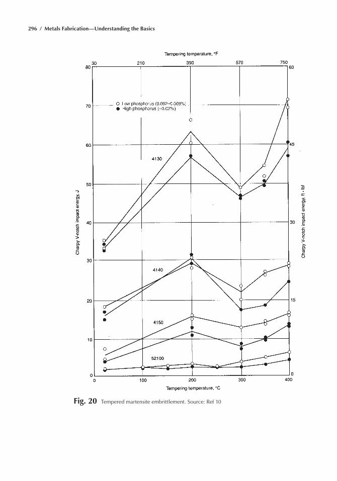
296 / Metals Fabrication—Understanding the Basics
Fig. 20 tempered martensite embrittlement. Source: ref 10
Chapter 6: Heat Treatment / 297
microstructures. these times are typically about an hour. the fracture paths are transgranular and the failure mode is often a mixture of cleav-age and microvoid coalescence. however, when the steel contains high amounts of phosphorous (e.g., 0.03% p), embrittlement is associated with intergranular failure along prior austenite grain boundaries. this suggests that the embrittlement is also associated with a loss of cohesive strength across prior austenite grain boundaries due to the segregation of impurities within the steel as well as with precipitates of cementite. it is thought to be due to the impurity elements phosphorous, nitrogen, and possibly sulfur. manganese may play an indirect role by helping the impurity elements segregate to the grain boundaries.
Temper Embrittlement
this type of embrittlement causes a decrease in notch toughness when tempered alloy steels are isothermally aged in the temperature range of 370 to 560 °C (700 to 1040 °f) or are slowly cooled after tempering. two-step embrittlement results in intergranular failure modes and is also attributed to the presence of impurities that segregate to the grain boundaries. the ductile-to-brittle transition is directly dependent on the grain-boundary concentration of impurities. the relative effect of these impurities has been found to be tin > antimony > phosphorous. alloying elements can also cosegregate to the grain boundaries along with the impurities; for example, nickel cosegregates with antimony. the rate and amount of impurity seg-regation, and hence the resultant intergranular embrittlement, depend on the total composition of the system. nickel, chromium, silicon, and man-ganese increase two-step temper embrittlement caused by antimony, tin, phosphorous, or arsenic. however, addition of molybdenum retards temper embrittlement because molybdenum inhibits the segregation of impurities; that is, molybdenum readily precipitates as phosphides in the matrix and inhibits segregation. heating to over 600 °C (1110 °f) followed by rapid cooling can reverse this type of embrittlement.
Surface Hardening of Steel
there are some applications where it is necessary to have a hard wear-resistant surface but a tough shock-resistant inner core. for example, cams, gears, and shafts require hard surfaces to resist wear but tough inner cores to resist shock. While a low-carbon steel containing 0.1% C will contain a tough core, its surface hardness will be low after harden-ing. On the other hand, a high-carbon steel containing 0.8% C will have a high surface hardness after hardening but the core will not be tough and shock resistant. there are two approaches to this problem. One is to use a medium-carbon steel and only harden the surface through heat treat-
298 / Metals Fabrication—Understanding the Basics
ment. the other approach is to diffuse carbon into the surface layers of low-carbon steel. When heat treated, the high-carbon surface layers will attain a much higher hardness than the low-carbon core. this method of case hardening, called carburizing, is feasible if small, fast diffusing ele-ments, such as carbon or nitrogen, that will form hard carbides or nitrides are used.
Surface Hardening by Localized Heat Treatment
Because these processes require a high enough carbon content to obtain the required hardness, a medium-carbon steel with a carbon content of 0.35 to 0.50% is usually selected. initially, the part is hardened by conventional quenching and tempering to produce the desired core hardness. Some-times normalizing will produce the desired core hardness. the surface is then reheated into the austenitization range and immediately quenched to produce fresh martensite at the surface. the part is then retempered to produce the desired surface hardness. the hard surface layers and the soft core will generally be separated by a cushion layer of bainite that helps in reducing cracking and spalling. in addition to the hard surface, the surface layer is usually in a state of compression, which improves fatigue cracking resistance.
Flame Hardening
The objective of flame hardening is to austenitize the steel at and near the surface and then to remove the flame and rapidly quench the work to produce martensite on the surface. The surface is heated by a gas flame created by burning acetylene, propane, or natural gas. the relatively low thermal conductivity of steel enables the surface regions to be austenitized using high rates of energy input without the interior being significantly affected. flame hardening can be as simple as an operator with a torch or can consist of automated systems equipped with quench jets that follow right behind the torches. the torch can also be used to temper the martens-ite. many variations are used, ranging from handheld torches to automated ignition, burn, and quench assemblies—for example, a rotating shaft within a surrounding stationary array of burners.
Flame hardening is a very rapid and efficient method for producing cases as deep as 6.3 mm (1/4 in.), but the maximum hardness that can be obtained (50 to 60 hrC) is less than can be attained with through hard-ening. Unless the process is automated, it can be difficult to control the case depth, and prolonged heating can result in a case depth deeper than desired. Because only the surface is hardened, when the part is quenched, there is less chance of distortion or warpage. it is often used where small quantities of parts require hardening, the part is large and bulky, or the heat treating facilities are limited.
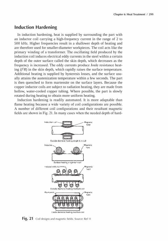
Chapter 6: Heat Treatment / 299
Induction Hardening
in induction hardening, heat is supplied by surrounding the part with an inductor coil carrying a high-frequency current in the range of 2 to 500 khz. higher frequencies result in a shallower depth of heating and are therefore used for smaller-diameter workpieces. the coil acts like the primary winding of a transformer. The oscillating field produced by the induction coil induces electrical eddy currents in the steel within a certain depth of the outer surface called the skin depth, which decreases as the frequency is increased. The eddy currents produce Joule resistance heat-ing (I2R) in the skin depth, which rapidly raises the surface temperature. additional heating is supplied by hysteresis losses, and the surface usu-ally attains the austenization temperature within a few seconds. the part is then quenched to form martensite on the surface layers. Because the copper inductor coils are subject to radiation heating, they are made from hollow, water-cooled copper tubing. Where possible, the part is slowly rotated during heating to obtain more uniform heating.
induction hardening is readily automated. it is more adaptable than flame heating because a wide variety of coil configurations are possible. A number of different coil configurations and their resultant magnetic fields are shown in Fig. 21. In many cases when the needed depth of hard-
Fig. 21 Coil designs and magnetic fields. Source: ref 11
300 / Metals Fabrication—Understanding the Basics
ening is quite shallow, the induction heating time is completed within a few seconds. irregular shapes can be handled quite readily with induction heating. Skin current can penetrate crevices and holes, as well as exterior surfaces. To provide a uniform starting fine-grained microstructure, the steel is often normalized prior to induction hardening.
induction hardening is generally used to produce relatively thin cases. Larger depths, such as 3.2 mm (1/8 in.), can be attained by leaving the current in contact with the surface for a longer period of time and by operating at lower frequencies. the case depth can be controlled more accurately in induction hardening than with other processes. the depth can be controlled by varying the frequency, the current, and the amount of time the current is in contact with the part. the higher the frequency, the more the current tends to flow over the outer surface only. Induction hardening provides outstanding resistance to warpage, distortion, oxidation, and scale formation due to the short heating time and to the fact that only a small portion of the part requires heating.
in short-duration induction heating processes, the depth to which the steel is austenitized is small. Shape changes due to thermal expansion and transformation of structure are accommodated by plastic flow in the hot metal. then, when the rim transforms to martensite during cooling, it tries to expand but the core is relatively cool and resists plastic flow. The result is that the surface is often in compression, which improves fatigue resistance. During treatments in which the heating depth is greater, the situation can be reversed and the surface can be put into tension, which is, of course, detrimental to fatigue resistance.
the main disadvantage of induction hardening is the cost of the equip-ment and the requirement for a skilled technician to initially set up the process. however, once it is set up, a relatively unskilled technician can operate it.
Case Hardening
The surface hardness of low-carbon steels can be increased significantly by diffusing carbon into the surface layers at elevated temperatures, fol-lowed by quenching and tempering. Because the surface layers contain a higher carbon content than the core, the surface layers attain a much higher hardness than the inner core during heat treatment. the end result is a hard wear resistance surface with a tough inner core. this process, called carburizing, is one of several case-hardening processes. another case-hardening process is nitriding. Because nitriding is done at a lower temperature, the part is quenched and tempered before nitriding. a third process, called carbonitriding, which is similar to carburizing, diffuses both carbon and nitrogen atoms into the surface.
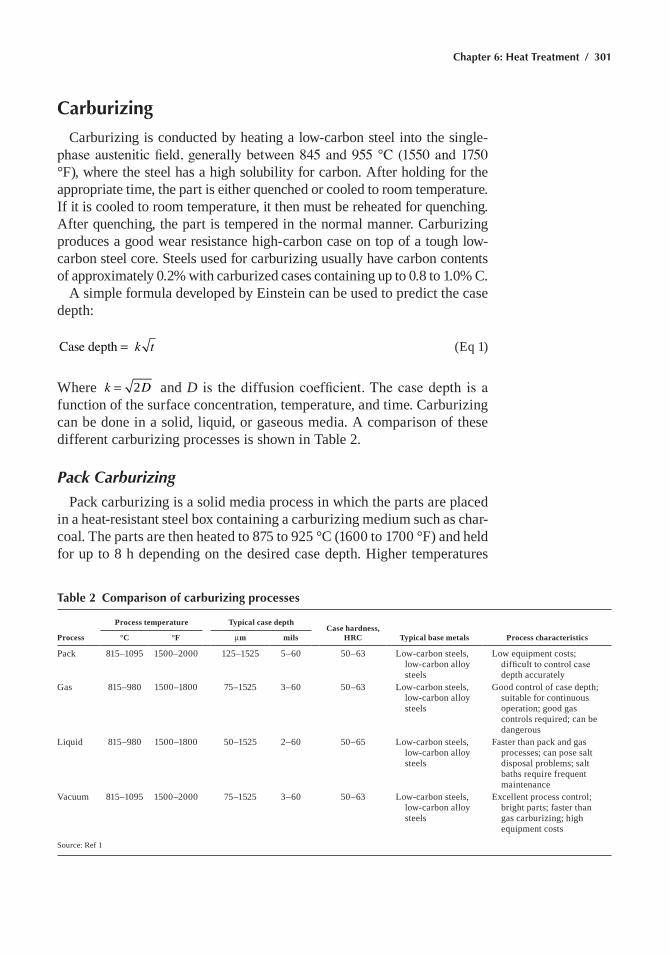
Chapter 6: Heat Treatment / 301
Carburizing
Carburizing is conducted by heating a low-carbon steel into the single-phase austenitic field, generally between 845 and 955 °C (1550 and 1750 °f), where the steel has a high solubility for carbon. after holding for the appropriate time, the part is either quenched or cooled to room temperature. if it is cooled to room temperature, it then must be reheated for quenching. after quenching, the part is tempered in the normal manner. Carburizing produces a good wear resistance high-carbon case on top of a tough low-carbon steel core. Steels used for carburizing usually have carbon contents of approximately 0.2% with carburized cases containing up to 0.8 to 1.0% C.
a simple formula developed by einstein can be used to predict the case depth:
= k tCase depth (eq 1)
Where =k D2 and D is the diffusion coefficient. The case depth is a function of the surface concentration, temperature, and time. Carburizing can be done in a solid, liquid, or gaseous media. a comparison of these different carburizing processes is shown in table 2.
Pack Carburizing
pack carburizing is a solid media process in which the parts are placed in a heat-resistant steel box containing a carburizing medium such as char-coal. the parts are then heated to 875 to 925 °C (1600 to 1700 °f) and held for up to 8 h depending on the desired case depth. higher temperatures
Table 2 Comparison of carburizing processes
Process
Process temperature Typical case depthCase hardness,
HRC Typical base metals Process characteristics°C °F mm mils
pack 815–1095 1500–2000 125–1525 5–60 50–63 Low-carbon steels, low-carbon alloy steels
Low equipment costs; difficult to control case depth accurately
Gas 815–980 1500–1800 75–1525 3–60 50–63 Low-carbon steels, low-carbon alloy steels
Good control of case depth; suitable for continuous operation; good gas controls required; can be dangerous
Liquid 815–980 1500–1800 50–1525 2–60 50–65 Low-carbon steels, low-carbon alloy steels
faster than pack and gas processes; can pose salt disposal problems; salt baths require frequent maintenance
Vacuum 815–1095 1500–2000 75–1525 3–60 50–63 Low-carbon steels, low-carbon alloy steels
excellent process control; bright parts; faster than gas carburizing; high equipment costs
Source: ref 1
302 / Metals Fabrication—Understanding the Basics
and longer times can be used to produce a greater case depth. the car-bonaceous material combines with air present in the box to form carbon monoxide.
C + O2 Æ CO (eq 2)
Carbon monoxide then decomposes into carbon dioxide and carbon atoms, with the carbon atoms then diffusing into the steel surface.
2CO Æ CO2 +C (eq 3)
Barium carbonate (10 to 15%) is usually added to facilitate the reaction. Barium carbonate dissociates to form:
BaCO3 Æ BaO + CO2 (eq 4)
and the carbon dioxide then reacts with charcoal to form carbon monoxide:
CO2 + C ´ 2CO (eq 5)
note that this reaction is reversible, and as the temperature is increased, the rate of carburization increases. Because the rate of change in case depth at a particular carburizing temperature is proportional to the square root of time, the rate of carburization is highest at the beginning of the cycle and gradually diminishes as the cycle is extended. if it is necessary to prevent any areas from being carburized, they can be masked by elec-troplating with copper to a thickness of 0.075 to 0.10 mm (0.003 to 0.004 in.). at the carburizing temperature, carbon is insoluble in copper.
pack carburizing has several advantages over other case-hardening pro-cesses. it involves minimal capital expense and is fairly foolproof. it is especially practical when only a few small parts require surface hardening at one time. the main disadvantage is that the process is rather slow and dirty.
Liquid Carburizing
Liquid carburizing is carried out in a bath of fused salt containing 20 to 50% sodium cyanide, up to 40% sodium carbonate, and varying amounts of either sodium or barium chloride. the bath temperature ranges from 870 to 955 °C (1600 to 1750 °f). Carburization time ranges from 5 min up to 1 h, depending on the desired case thickness. Salt bath carburizing is often conducted on small parts that are loaded in baskets that are then immersed in the bath. after carburizing, the parts can be immediately quenched to produce the martensitic case. the process is useful for producing relatively shallow cases of 0.10 to 0.25 mm (0.004 to 0.010 in.), although case depths
Chapter 6: Heat Treatment / 303
as deep as 5.0 mm (0.20 in.) can be produced. Because the bath contains sodium cyanide (naCnO), some nitrogen is also released and diffuses into the surface to produce additional hardness. Because some nitrogen is absorbed into the surface and immediately hardens the part, parts that are liquid carburized are generally not machined after carburizing. an advan-tage of salt baths is that they offer fast heating and accurate temperature control. On the downside, cyanides are extremely poisonous, and efficient fume extraction systems are required and waste disposal is problematic. in addition, the parts must be rinsed to remove the salts after carburizing to prevent rusting.
Different bath temperatures can be used to produce different case depths, with low-temperature baths producing shallower cases and high-temperature baths producing deeper cases. Low-temperature cyanide baths (light-case baths) are usually operated in the temperature range of 845 to 900 °C (1550 to 1650 °F), although for certain specific effects this range is sometimes extended to 790 to 925 °C (1450 to 1700 °f). high-temperature cyanide baths (deep-case baths) are usually operated in the temperature range of 900 to 955 °C (1650 to 1750 °f). high-temperature baths are used for producing cases 0.50 to 3.0 mm (0.020 to 0.120 in.) deep. in some instances, even deeper cases are produced, up to approximately 6.4 mm (0.250 in.), but the most important use of these baths is for the rapid development of cases 1.0 to 2.0 mm (0.040 to 0.080 in.) deep.
Salt baths are usually contained in relatively small chambers or tanks, so it can be impractical to immerse large, odd-shaped parts into the liq-uid. for this reason, liquid carburizing is usually restricted to the surface hardening of small parts.
Gas Carburizing
the vast majority of carburized parts are processed by gas carburiz-ing, using natural gas, propane, or butane. in gas carburizing, the part is heated to approximately 900 °C (1650 °f) for 3 to 4 h in a carbon-rich atmosphere, usually a mixture of carbon monoxide and water vapor. typi-cal case depths are less than 2.5 mm (0.1 in.), usually in the range of 0.5 to 1.5 mm (0.020 to 0.060 in.) Carburization temperatures are usually in the range of 845 to 955 °C (1550 to 1750 °f). Carburization times depend on the desired case depth. A common definition of the case depth is that depth below the surface at which the hardness is 50 HRC in the final quenched and tempered part.
in gas carburizing, carbon is transferred from the carburizing atmo-sphere to the part surface. the carbon then diffuses slowly into the bulk of the part, establishing a carbon concentration gradient below the surface. the driving force for the carburizing reaction is called the carbon potential. Within the steel part, the high-carbon surface has a higher carbon potential than the low-carbon interior; thus, carbon tends to diffuse from the surface
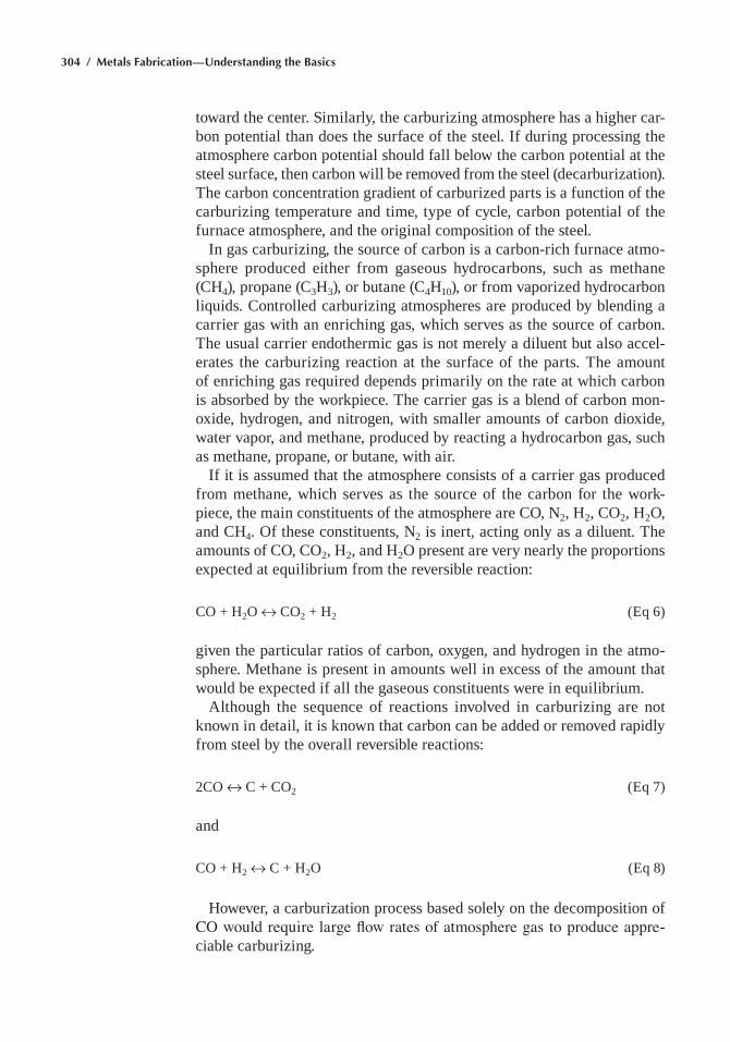
304 / Metals Fabrication—Understanding the Basics
toward the center. Similarly, the carburizing atmosphere has a higher car-bon potential than does the surface of the steel. if during processing the atmosphere carbon potential should fall below the carbon potential at the steel surface, then carbon will be removed from the steel (decarburization). the carbon concentration gradient of carburized parts is a function of the carburizing temperature and time, type of cycle, carbon potential of the furnace atmosphere, and the original composition of the steel.
in gas carburizing, the source of carbon is a carbon-rich furnace atmo-sphere produced either from gaseous hydrocarbons, such as methane (Ch4), propane (C3h3), or butane (C4h10), or from vaporized hydrocarbon liquids. Controlled carburizing atmospheres are produced by blending a carrier gas with an enriching gas, which serves as the source of carbon. the usual carrier endothermic gas is not merely a diluent but also accel-erates the carburizing reaction at the surface of the parts. the amount of enriching gas required depends primarily on the rate at which carbon is absorbed by the workpiece. the carrier gas is a blend of carbon mon-oxide, hydrogen, and nitrogen, with smaller amounts of carbon dioxide, water vapor, and methane, produced by reacting a hydrocarbon gas, such as methane, propane, or butane, with air.
if it is assumed that the atmosphere consists of a carrier gas produced from methane, which serves as the source of the carbon for the work-piece, the main constituents of the atmosphere are CO, n2, h2, CO2, h2O, and Ch4. Of these constituents, n2 is inert, acting only as a diluent. the amounts of CO, CO2, h2, and h2O present are very nearly the proportions expected at equilibrium from the reversible reaction:
CO + h2O ´ CO2 + h2 (eq 6)
given the particular ratios of carbon, oxygen, and hydrogen in the atmo-sphere. methane is present in amounts well in excess of the amount that would be expected if all the gaseous constituents were in equilibrium.
although the sequence of reactions involved in carburizing are not known in detail, it is known that carbon can be added or removed rapidly from steel by the overall reversible reactions:
2CO ´ C + CO2 (eq 7)
and
CO + h2 ´ C + h2O (eq 8)
however, a carburization process based solely on the decomposition of CO would require large flow rates of atmosphere gas to produce appre-ciable carburizing.
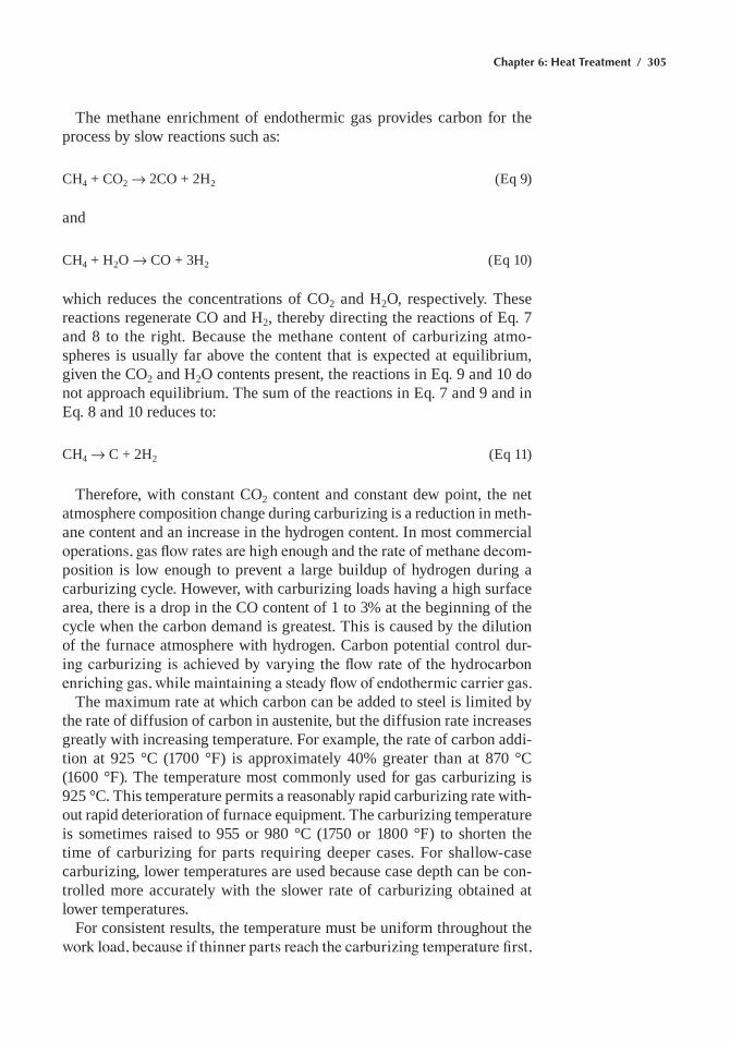
Chapter 6: Heat Treatment / 305
the methane enrichment of endothermic gas provides carbon for the process by slow reactions such as:
Ch4 + CO2 Æ 2CO + 2h2 (eq 9)
and
Ch4 + h2O Æ CO + 3h2 (eq 10)
which reduces the concentrations of CO2 and h2O, respectively. these reactions regenerate CO and h2, thereby directing the reactions of eq. 7 and 8 to the right. Because the methane content of carburizing atmo-spheres is usually far above the content that is expected at equilibrium, given the CO2 and h2O contents present, the reactions in eq. 9 and 10 do not approach equilibrium. the sum of the reactions in eq. 7 and 9 and in eq. 8 and 10 reduces to:
Ch4 Æ C + 2h2 (eq 11)
therefore, with constant CO2 content and constant dew point, the net atmosphere composition change during carburizing is a reduction in meth-ane content and an increase in the hydrogen content. in most commercial operations, gas flow rates are high enough and the rate of methane decom-position is low enough to prevent a large buildup of hydrogen during a carburizing cycle. however, with carburizing loads having a high surface area, there is a drop in the CO content of 1 to 3% at the beginning of the cycle when the carbon demand is greatest. this is caused by the dilution of the furnace atmosphere with hydrogen. Carbon potential control dur-ing carburizing is achieved by varying the flow rate of the hydrocarbon enriching gas, while maintaining a steady flow of endothermic carrier gas.
the maximum rate at which carbon can be added to steel is limited by the rate of diffusion of carbon in austenite, but the diffusion rate increases greatly with increasing temperature. for example, the rate of carbon addi-tion at 925 °C (1700 °f) is approximately 40% greater than at 870 °C (1600 °f). the temperature most commonly used for gas carburizing is 925 °C. this temperature permits a reasonably rapid carburizing rate with-out rapid deterioration of furnace equipment. the carburizing temperature is sometimes raised to 955 or 980 °C (1750 or 1800 °f) to shorten the time of carburizing for parts requiring deeper cases. for shallow-case carburizing, lower temperatures are used because case depth can be con-trolled more accurately with the slower rate of carburizing obtained at lower temperatures.
for consistent results, the temperature must be uniform throughout the work load, because if thinner parts reach the carburizing temperature first,
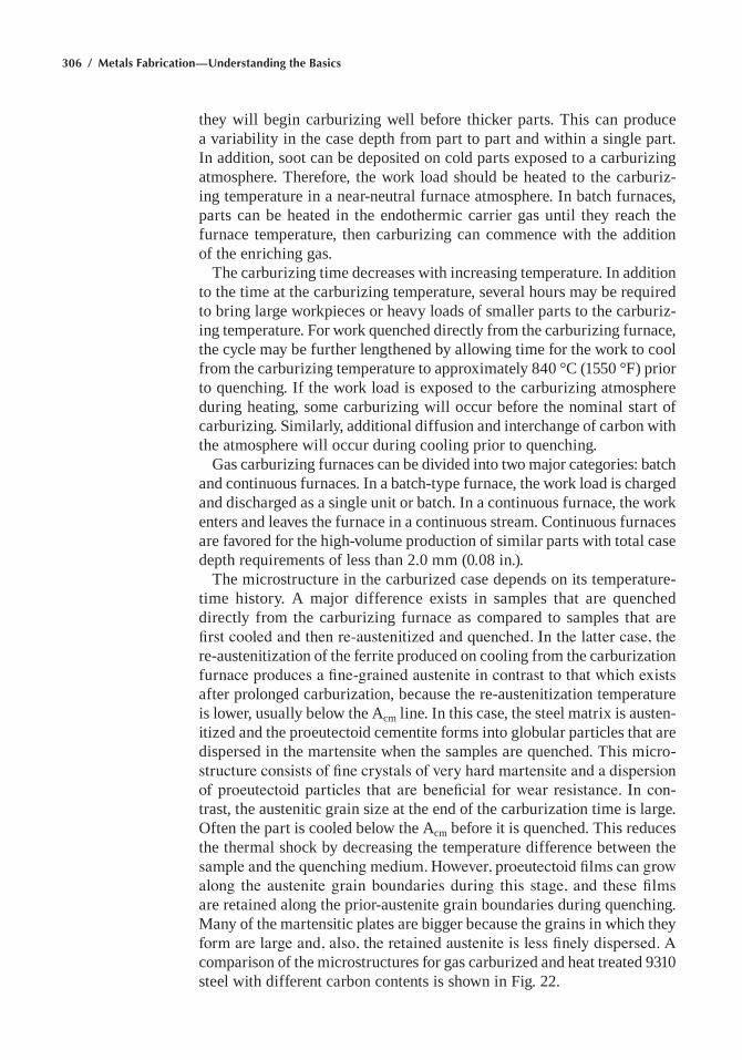
306 / Metals Fabrication—Understanding the Basics
they will begin carburizing well before thicker parts. this can produce a variability in the case depth from part to part and within a single part. in addition, soot can be deposited on cold parts exposed to a carburizing atmosphere. therefore, the work load should be heated to the carburiz-ing temperature in a near-neutral furnace atmosphere. in batch furnaces, parts can be heated in the endothermic carrier gas until they reach the furnace temperature, then carburizing can commence with the addition of the enriching gas.
the carburizing time decreases with increasing temperature. in addition to the time at the carburizing temperature, several hours may be required to bring large workpieces or heavy loads of smaller parts to the carburiz-ing temperature. for work quenched directly from the carburizing furnace, the cycle may be further lengthened by allowing time for the work to cool from the carburizing temperature to approximately 840 °C (1550 °f) prior to quenching. if the work load is exposed to the carburizing atmosphere during heating, some carburizing will occur before the nominal start of carburizing. Similarly, additional diffusion and interchange of carbon with the atmosphere will occur during cooling prior to quenching.
Gas carburizing furnaces can be divided into two major categories: batch and continuous furnaces. in a batch-type furnace, the work load is charged and discharged as a single unit or batch. in a continuous furnace, the work enters and leaves the furnace in a continuous stream. Continuous furnaces are favored for the high-volume production of similar parts with total case depth requirements of less than 2.0 mm (0.08 in.).
the microstructure in the carburized case depends on its temperature-time history. a major difference exists in samples that are quenched directly from the carburizing furnace as compared to samples that are first cooled and then re-austenitized and quenched. In the latter case, the re-austenitization of the ferrite produced on cooling from the carburization furnace produces a fine-grained austenite in contrast to that which exists after prolonged carburization, because the re-austenitization temperature is lower, usually below the acm line. in this case, the steel matrix is austen-itized and the proeutectoid cementite forms into globular particles that are dispersed in the martensite when the samples are quenched. this micro-structure consists of fine crystals of very hard martensite and a dispersion of proeutectoid particles that are beneficial for wear resistance. In con-trast, the austenitic grain size at the end of the carburization time is large. Often the part is cooled below the acm before it is quenched. this reduces the thermal shock by decreasing the temperature difference between the sample and the quenching medium. However, proeutectoid films can grow along the austenite grain boundaries during this stage, and these films are retained along the prior-austenite grain boundaries during quenching. many of the martensitic plates are bigger because the grains in which they form are large and, also, the retained austenite is less finely dispersed. A comparison of the microstructures for gas carburized and heat treated 9310 steel with different carbon contents is shown in fig. 22.
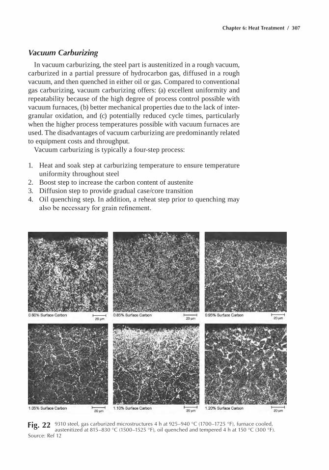
Chapter 6: Heat Treatment / 307
Vacuum Carburizing
in vacuum carburizing, the steel part is austenitized in a rough vacuum, carburized in a partial pressure of hydrocarbon gas, diffused in a rough vacuum, and then quenched in either oil or gas. Compared to conventional gas carburizing, vacuum carburizing offers: (a) excellent uniformity and repeatability because of the high degree of process control possible with vacuum furnaces, (b) better mechanical properties due to the lack of inter-granular oxidation, and (c) potentially reduced cycle times, particularly when the higher process temperatures possible with vacuum furnaces are used. the disadvantages of vacuum carburizing are predominantly related to equipment costs and throughput.
Vacuum carburizing is typically a four-step process:
1. heat and soak step at carburizing temperature to ensure temperature uniformity throughout steel
2. Boost step to increase the carbon content of austenite3. Diffusion step to provide gradual case/core transition4. Oil quenching step. in addition, a reheat step prior to quenching may
also be necessary for grain refinement.
Fig. 22 9310 steel, gas carburized microstructures 4 h at 925–940 °C (1700–1725 °F), furnace cooled, austenitized at 815–830 °C (1500–1525 °F), oil quenched and tempered 4 h at 150 °C (300 °F).
Source: ref 12
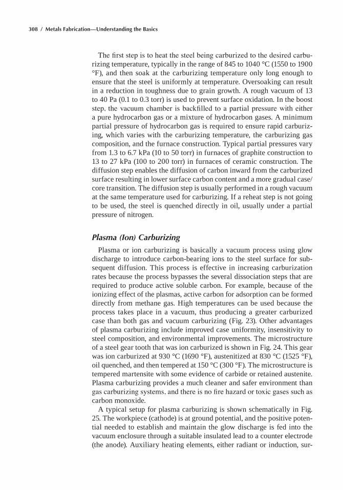
308 / Metals Fabrication—Understanding the Basics
The first step is to heat the steel being carburized to the desired carbu-rizing temperature, typically in the range of 845 to 1040 °C (1550 to 1900 °f), and then soak at the carburizing temperature only long enough to ensure that the steel is uniformly at temperature. Oversoaking can result in a reduction in toughness due to grain growth. a rough vacuum of 13 to 40 pa (0.1 to 0.3 torr) is used to prevent surface oxidation. in the boost step, the vacuum chamber is backfilled to a partial pressure with either a pure hydrocarbon gas or a mixture of hydrocarbon gases. a minimum partial pressure of hydrocarbon gas is required to ensure rapid carburiz-ing, which varies with the carburizing temperature, the carburizing gas composition, and the furnace construction. typical partial pressures vary from 1.3 to 6.7 kpa (10 to 50 torr) in furnaces of graphite construction to 13 to 27 kpa (100 to 200 torr) in furnaces of ceramic construction. the diffusion step enables the diffusion of carbon inward from the carburized surface resulting in lower surface carbon content and a more gradual case/core transition. the diffusion step is usually performed in a rough vacuum at the same temperature used for carburizing. if a reheat step is not going to be used, the steel is quenched directly in oil, usually under a partial pressure of nitrogen.
Plasma (Ion) Carburizing
plasma or ion carburizing is basically a vacuum process using glow discharge to introduce carbon-bearing ions to the steel surface for sub-sequent diffusion. this process is effective in increasing carburization rates because the process bypasses the several dissociation steps that are required to produce active soluble carbon. for example, because of the ionizing effect of the plasmas, active carbon for adsorption can be formed directly from methane gas. high temperatures can be used because the process takes place in a vacuum, thus producing a greater carburized case than both gas and vacuum carburizing (fig. 23). Other advantages of plasma carburizing include improved case uniformity, insensitivity to steel composition, and environmental improvements. the microstructure of a steel gear tooth that was ion carburized is shown in fig. 24. this gear was ion carburized at 930 °C (1690 °f), austenitized at 830 °C (1525 °f), oil quenched, and then tempered at 150 °C (300 °f). the microstructure is tempered martensite with some evidence of carbide or retained austenite. plasma carburizing provides a much cleaner and safer environment than gas carburizing systems, and there is no fire hazard or toxic gases such as carbon monoxide.
a typical setup for plasma carburizing is shown schematically in fig. 25. the workpiece (cathode) is at ground potential, and the positive poten-tial needed to establish and maintain the glow discharge is fed into the vacuum enclosure through a suitable insulated lead to a counter electrode (the anode). auxiliary heating elements, either radiant or induction, sur-
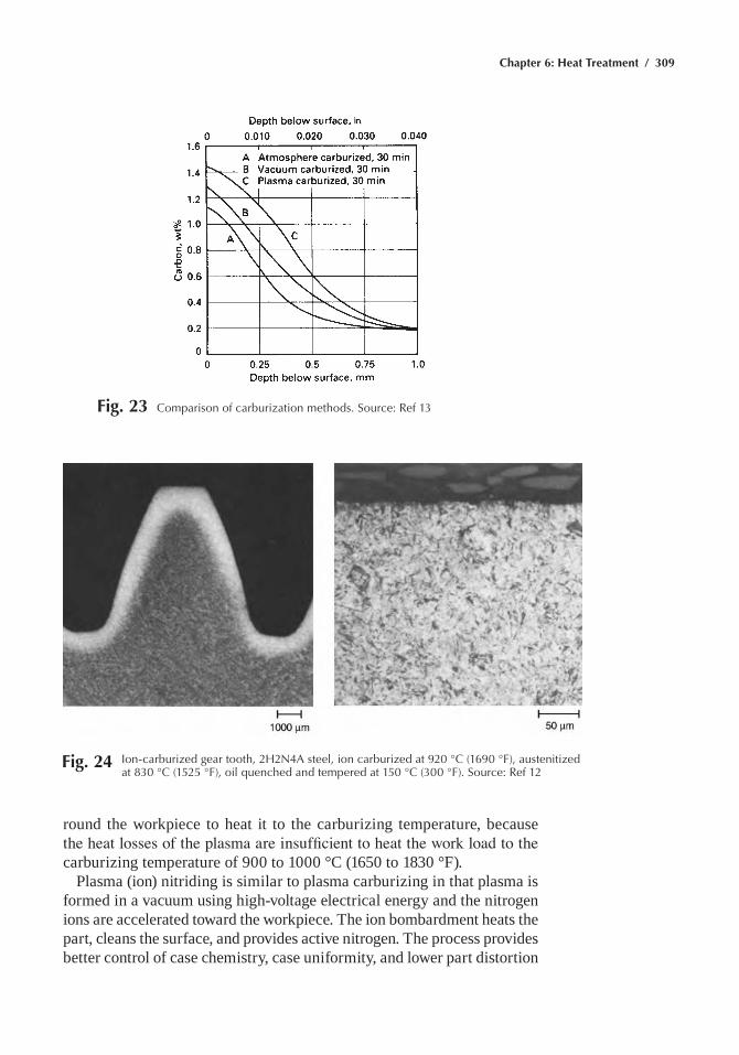
Chapter 6: Heat Treatment / 309
round the workpiece to heat it to the carburizing temperature, because the heat losses of the plasma are insufficient to heat the work load to the carburizing temperature of 900 to 1000 °C (1650 to 1830 °f).
plasma (ion) nitriding is similar to plasma carburizing in that plasma is formed in a vacuum using high-voltage electrical energy and the nitrogen ions are accelerated toward the workpiece. the ion bombardment heats the part, cleans the surface, and provides active nitrogen. the process provides better control of case chemistry, case uniformity, and lower part distortion
Fig. 23 Comparison of carburization methods. Source: ref 13
Fig. 24 Ion-carburized gear tooth, 2h2N4a steel, ion carburized at 920 °C (1690 °F), austenitized at 830 °C (1525 °F), oil quenched and tempered at 150 °C (300 °F). Source: ref 12
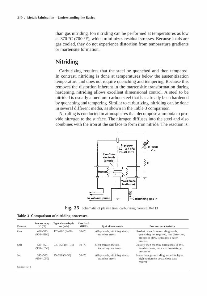
310 / Metals Fabrication—Understanding the Basics
than gas nitriding. ion nitriding can be performed at temperatures as low as 370 °C (700 °f), which minimizes residual stresses. Because loads are gas cooled, they do not experience distortion from temperature gradients or martensite formation.
Nitriding
Carburizing requires that the steel be quenched and then tempered. in contrast, nitriding is done at temperatures below the austenitization temperature and does not require quenching and tempering. Because this removes the distortion inherent in the martensitic transformation during hardening, nitriding allows excellent dimensional control. a steel to be nitrided is usually a medium-carbon steel that has already been hardened by quenching and tempering. Similar to carburizing, nitriding can be done in several different media, as shown in the table 3 comparison.
nitriding is conducted in atmospheres that decompose ammonia to pro-vide nitrogen to the surface. the nitrogen diffuses into the steel and also combines with the iron at the surface to form iron nitride. the reaction is:
Fig. 25 Schematic of plasma (ion) carburizing. Source: ref 13
Table 3 Comparison of nitriding processes
ProcessProcess temp.
°C (°F)Typical case depth,
µm (mils)Case hard.
(HRC) Typical base metals Process characteristics
Gas 480–595 (900–1100)
125–760 (5–30) 50–70 alloy steels, nitriding steels, stainless steels
hardest cases from nitriding steels, quenching not required, low distortion, process is slow, is usually a batch process
Salt 510–565 (950–1050)
2.5–760 (0.1–30) 50–70 most ferrous metals, including cast irons
Usually used for thin, hard cases <1 mil, no white layer, most are proprietary processes
ion 345–565 (650–1050)
75–760 (3–30) 50–70 alloy steels, nitriding steels, stainless steels
faster than gas nitriding, no white layer, high equipment costs, close case control
Source: ref 1
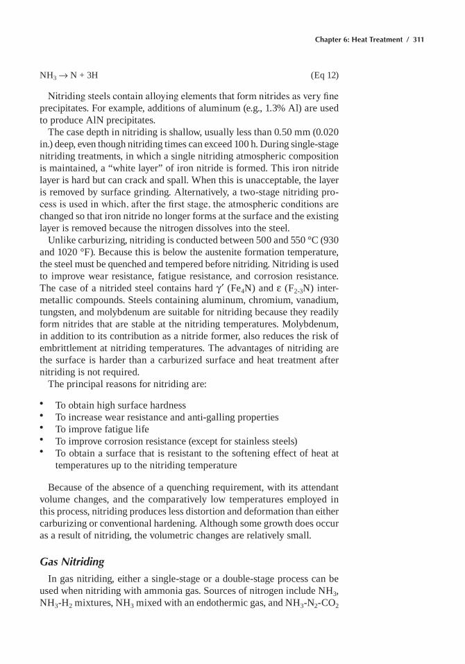
Chapter 6: Heat Treatment / 311
nh3 Æ n + 3h (eq 12)
Nitriding steels contain alloying elements that form nitrides as very fine precipitates. for example, additions of aluminum (e.g., 1.3% al) are used to produce aln precipitates.
the case depth in nitriding is shallow, usually less than 0.50 mm (0.020 in.) deep, even though nitriding times can exceed 100 h. During single-stage nitriding treatments, in which a single nitriding atmospheric composition is maintained, a “white layer” of iron nitride is formed. this iron nitride layer is hard but can crack and spall. When this is unacceptable, the layer is removed by surface grinding. alternatively, a two-stage nitriding pro-cess is used in which, after the first stage, the atmospheric conditions are changed so that iron nitride no longer forms at the surface and the existing layer is removed because the nitrogen dissolves into the steel.
Unlike carburizing, nitriding is conducted between 500 and 550 °C (930 and 1020 °f). Because this is below the austenite formation temperature, the steel must be quenched and tempered before nitriding. nitriding is used to improve wear resistance, fatigue resistance, and corrosion resistance. the case of a nitrided steel contains hard γ ¢ (fe4n) and ε (f2-3n) inter-metallic compounds. Steels containing aluminum, chromium, vanadium, tungsten, and molybdenum are suitable for nitriding because they readily form nitrides that are stable at the nitriding temperatures. molybdenum, in addition to its contribution as a nitride former, also reduces the risk of embrittlement at nitriding temperatures. the advantages of nitriding are the surface is harder than a carburized surface and heat treatment after nitriding is not required.
the principal reasons for nitriding are:
• to obtain high surface hardness• to increase wear resistance and anti-galling properties• to improve fatigue life• to improve corrosion resistance (except for stainless steels)• to obtain a surface that is resistant to the softening effect of heat at
temperatures up to the nitriding temperature
Because of the absence of a quenching requirement, with its attendant volume changes, and the comparatively low temperatures employed in this process, nitriding produces less distortion and deformation than either carburizing or conventional hardening. although some growth does occur as a result of nitriding, the volumetric changes are relatively small.
Gas Nitriding
in gas nitriding, either a single-stage or a double-stage process can be used when nitriding with ammonia gas. Sources of nitrogen include nh3, nh3-h2 mixtures, nh3 mixed with an endothermic gas, and nh3-n2-CO2
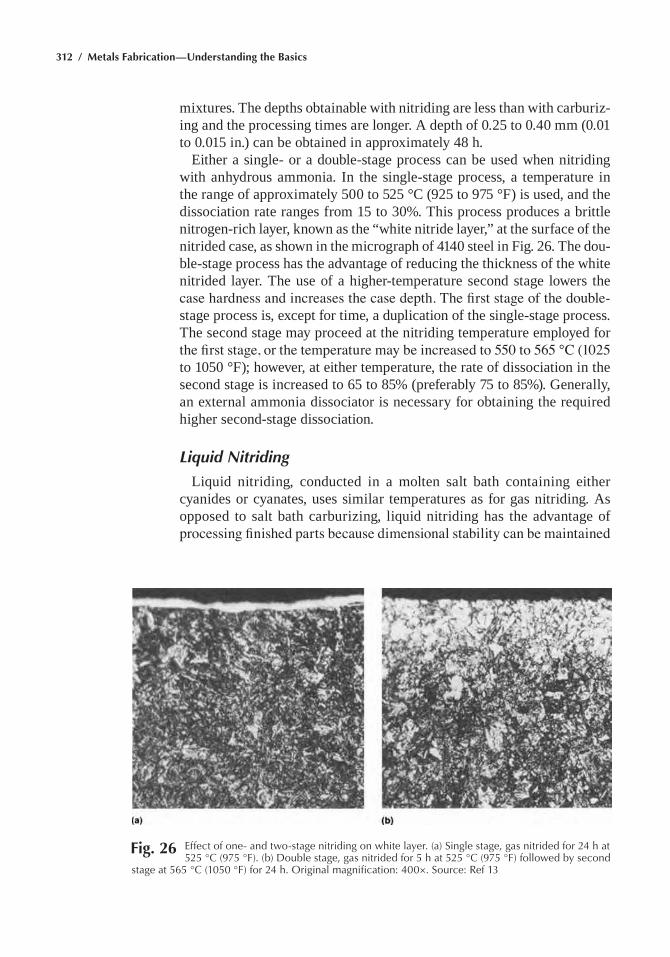
312 / Metals Fabrication—Understanding the Basics
mixtures. the depths obtainable with nitriding are less than with carburiz-ing and the processing times are longer. a depth of 0.25 to 0.40 mm (0.01 to 0.015 in.) can be obtained in approximately 48 h.
either a single- or a double-stage process can be used when nitriding with anhydrous ammonia. in the single-stage process, a temperature in the range of approximately 500 to 525 °C (925 to 975 °f) is used, and the dissociation rate ranges from 15 to 30%. this process produces a brittle nitrogen-rich layer, known as the “white nitride layer,” at the surface of the nitrided case, as shown in the micrograph of 4140 steel in fig. 26. the dou-ble-stage process has the advantage of reducing the thickness of the white nitrided layer. the use of a higher-temperature second stage lowers the case hardness and increases the case depth. The first stage of the double-stage process is, except for time, a duplication of the single-stage process. the second stage may proceed at the nitriding temperature employed for the first stage, or the temperature may be increased to 550 to 565 °C (1025 to 1050 °f); however, at either temperature, the rate of dissociation in the second stage is increased to 65 to 85% (preferably 75 to 85%). Generally, an external ammonia dissociator is necessary for obtaining the required higher second-stage dissociation.
Liquid Nitriding
Liquid nitriding, conducted in a molten salt bath containing either cyanides or cyanates, uses similar temperatures as for gas nitriding. as opposed to salt bath carburizing, liquid nitriding has the advantage of processing finished parts because dimensional stability can be maintained
Fig. 26 effect of one- and two-stage nitriding on white layer. (a) Single stage, gas nitrided for 24 h at 525 °C (975 °F). (b) Double stage, gas nitrided for 5 h at 525 °C (975 °F) followed by second
stage at 565 °C (1050 °F) for 24 h. Original magnification: 400×. Source: ref 13
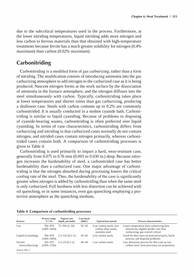
Chapter 6: Heat Treatment / 313
due to the subcritical temperatures used in the process. furthermore, at the lower nitriding temperatures, liquid nitriding adds more nitrogen and less carbon to ferrous materials than that obtained with high-temperature treatments because ferrite has a much greater solubility for nitrogen (0.4% maximum) than carbon (0.02% maximum).
Carbonitriding
Carbonitriding is a modified form of gas carburizing, rather than a form of nitriding. The modification consists of introducing ammonia into the gas carburizing atmosphere to add nitrogen to the carburized case as it is being produced. nascent nitrogen forms at the work surface by the dissociation of ammonia in the furnace atmosphere, and the nitrogen diffuses into the steel simultaneously with carbon. typically, carbonitriding takes place at lower temperatures and shorter times than gas carburizing, producing a shallower case. Steels with carbon contents up to 0.2% are commonly carbonitrided. it is usually conducted in a molten cyanide bath. Carboni-triding is similar to liquid cyaniding. Because of problems in disposing of cyanide-bearing wastes, carbonitriding is often preferred over liquid cyaniding. in terms of case characteristics, carbonitriding differs from carburizing and nitriding in that carburized cases normally do not contain nitrogen, and nitrided cases contain nitrogen primarily, whereas carboni-trided cases contain both. a comparison of carbonitriding processes is given in table 4.
Carbonitriding is used primarily to impart a hard, wear-resistant case, generally from 0.075 to 0.76 mm (0.003 to 0.030 in.) deep. Because nitro-gen increases the hardenability of steel, a carbonitrided case has better hardenability than a carburized case. One major advantage of carboni-triding is that the nitrogen absorbed during processing lowers the critical cooling rate of the steel. Thus, the hardenability of the case is significantly greater when nitrogen is added by carbonitriding than when the same steel is only carburized. full hardness with less distortion can be achieved with oil quenching, or in some instances, even gas quenching employing a pro-tective atmosphere as the quenching medium.
Table 4 Comparison of carbonitriding processes
ProcessProcess temp.
°C (°F)Typical case
depth, µm (mils)Case hard.
(HRC) Typical base metals Process characteristics
Gas 760–870 (1400–1600)
75–760 (3–30) 50–65 Low-carbon steels, low-carbon alloy steels, stainless steel
Lower temperature than carburizing (less distortion), slightly harder case than carburizing, gas control critical
Liquid (Cyaniding) 760–870 (1400–1600)
2.5–125 (0.1–5) 50–65 Low carbon steels Good for thin cases on noncritical parts, batch process, salt disposal problems
ferritic nitrocarburizing
565–675 (1050–1250)
2.5–25 (0.1–1) 40–60 Low carbon steels Low distortion process for thin case on low carbon steel, most processes are proprietary
Source: ref 1
314 / Metals Fabrication—Understanding the Basics
Often, carburizing and carbonitriding are used together to achieve much deeper case depths and better engineering performance than could be obtained by using only the carbonitriding process. the process gener-ally consists of carburizing at 900 to 925 °C (1650 to 1750 °f) to give the desired total case depth (up to 2.5 mm, or 0.100 in.), followed by carbo-nitriding for 2 to 6 h in the temperature range of 815 to 900 °C (1500 to 1650 °f) to add the additional carbonitrided case. the parts can then be oil quenched to obtain a deeper effective and harder case than would have resulted from the carburizing process alone. the addition of the carboni-trided surface increases the case residual compressive stress level and thus improves contact fatigue resistance, as well as increasing the case strength gradient. When the carburizing/carbonitriding processes are used together, the ratio of effective case depth at 50 hrC to total case depth may vary from approximately 0.35 to 0.75, depending on the case hardenability, core hardenability, section size, and quenchant used.
Precipitation Hardening
precipitation hardening is used extensively to strengthen aluminum alloys, magnesium alloys, nickel-base superalloys, beryllium-copper alloys, and precipitation-hardening (ph) stainless steels. in precipitation hardening, an alloy is heated to a high enough temperature to take a sig-nificant amount of an alloying element into solid solution. It is then rapidly cooled (quenched) to room temperature, trapping the alloying elements in solution. On reheating to an intermediate temperature, the host metal rejects the alloying element in the form of a fine precipitate that creates matrix strains in the lattice. These fine precipitate particles act as barri-ers to the motion of dislocations and provide resistance to slip, thereby increasing the strength and hardness.
Theory of Precipitation Hardening
a portion of a phase diagram for an alloy system that has the character-istics required for precipitation hardening is shown in fig. 27. note that the solvent metal at the left-hand edge of the diagram can absorb much more solute metal at elevated temperature than it can at room temperature. When the alloy is heated to the solution heat treating temperature and held for a sufficient length of time, the solvent metal absorbs some of the solute metal. then, when it is rapidly cooled (quenched) to room temperature, atoms of the solute metal are trapped as a supersaturated solid solution in the solvent metal. On reheating to an intermediate aging temperature, the supersaturated solution precipitates very fine particles that act as barriers to dislocation movement. note the effects of different aging temperatures shown in fig. 27. if the metal is aged at too low a temperature (t1), the precipitation process will be incomplete and the desired strength will not
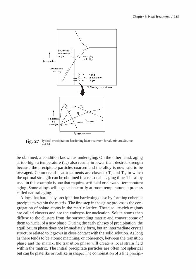
Chapter 6: Heat Treatment / 315
be obtained, a condition known as underaging. On the other hand, aging at too high a temperature (t4) also results in lower-than-desired strength because the precipitate particles coarsen and the alloy is now said to be overaged. Commercial heat treatments are closer to t2 and t3, in which the optimal strength can be obtained in a reasonable aging time. the alloy used in this example is one that requires artificial or elevated-temperature aging. Some alloys will age satisfactorily at room temperature, a process called natural aging.
alloys that harden by precipitation hardening do so by forming coherent precipitates within the matrix. The first step in the aging process is the con-gregation of solute atoms in the matrix lattice. these solute-rich regions are called clusters and are the embryos for nucleation. Solute atoms then diffuse to the clusters from the surrounding matrix and convert some of them to nuclei of a new phase. During the early phases of precipitation, the equilibrium phase does not immediately form, but an intermediate crystal structure related to it grows in close contact with the solid solution. as long as there tends to be atomic matching, or coherency, between the transition phase and the matrix, the transition phase will create a local strain field within the matrix. the initial precipitate particles are often not spherical but can be platelike or rodlike in shape. The combination of a fine precipi-
Fig. 27 typical precipitation-hardening heat treatment for aluminum. Source: ref 14
316 / Metals Fabrication—Understanding the Basics
tate size and the localized strain fields is an effective barrier to dislocation movement and thus increases the strength and hardness.
for effective precipitation hardening, either a coherent or semicoherent interface must be present. the lattice distortion produced by a coherent precipitate, which impedes dislocation motion, provides the hardening. Once the alloy is overaged, an incoherent interface develops that is accom-panied by softening of the alloy. the eventual formation of the equilibrium phase is always energetically favorable. if the alloy is aged at room tem-perature, equilibrium may never be achieved. however, when the alloy is aged at elevated temperature, either longer aging times or higher tem-peratures will result in the formation of the final equilibrium precipitate. Because the equilibrium precipitate is larger and more widely spaced, it no longer imposes a strain field on the matrix and is not nearly as effective in blocking dislocation motion, and the strength properties decrease. the equilibrium phase usually nucleates separately from a transition phase(s) and then competes with the less stable transition phase for solute atoms, eventually causing the transition phase to redissolve as it gets smaller. as the equilibrium phase grows, the sizes of the precipitate particles increase, their numbers decrease, and the distance between particles increases, all allowing easier passage of dislocations. it is important to remember that precipitation-hardened alloys are metastable; equilibrium is always lurking around the corner. all precipitation-hardened alloys will eventually soften if heated to high enough temperatures, or if they are exposed to somewhat lower temperatures for long periods of time. this being said, some are extremely stable at elevated temperatures, such as the ordered ni3(al,ti) precipitate in precipitation-hardened nickel-base superalloys that are used in the hottest portions of jet engines.
precipitate formation is not always uniform. Grain boundaries are high-energy sites and precipitates can often form along the grain boundaries. Some alloys will form discontinuous precipitates at the grain bound-aries, in which lamellae of the second phase are interspersed with the solute-depleted matrix. Small additions of nickel or cobalt are used in beryllium-copper alloys to minimize this effect because it adversely affects mechanical properties.
a number of alloy systems can be precipitation hardened. alumi-num alloys are one of the most important series of alloys that can be precipitation hardened, including the 2xxx (aluminum-copper), 6xxx (aluminum-magnesium-silicon), 7xxx (aluminum-zinc), and some of the 8xxx (aluminum-lithium) alloys. Some of the copper alloys, in particular beryllium-copper, can be precipitation hardened. the iron- and nickel-base superalloys are another particularly important class of precipitation-hard-ening alloys. in the nickel-base superalloys, the precipitate ni3(al,ti) has very little misfit with the nickel matrix (<2%), which produces very low strain energies (~10 to 30 mj/m2) and provides resistance to overaging for prolonged periods at high temperatures.
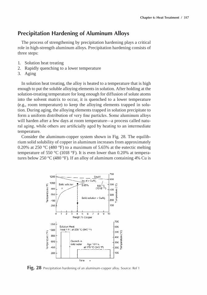
Chapter 6: Heat Treatment / 317
Precipitation Hardening of Aluminum Alloys
the process of strengthening by precipitation hardening plays a critical role in high-strength aluminum alloys. precipitation hardening consists of three steps:
1. Solution heat treating2. rapidly quenching to a lower temperature3. aging
in solution heat treating, the alloy is heated to a temperature that is high enough to put the soluble alloying elements in solution. after holding at the solution-treating temperature for long enough for diffusion of solute atoms into the solvent matrix to occur, it is quenched to a lower temperature (e.g., room temperature) to keep the alloying elements trapped in solu-tion. During aging, the alloying elements trapped in solution precipitate to form a uniform distribution of very fine particles. Some aluminum alloys will harden after a few days at room temperature—a process called natu-ral aging, while others are artificially aged by heating to an intermediate temperature.
Consider the aluminum-copper system shown in fig. 28. the equilib-rium solid solubility of copper in aluminum increases from approximately 0.20% at 250 °C (480 °f) to a maximum of 5.65% at the eutectic melting temperature of 550 °C (1018 °f). it is even lower than 0.20% at tempera-tures below 250 °C (480 °f). if an alloy of aluminum containing 4% Cu is
Fig. 28 precipitation hardening of an aluminum-copper alloy. Source: ref 1
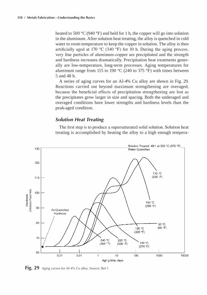
318 / Metals Fabrication—Understanding the Basics
heated to 500 °C (940 °f) and held for 1 h, the copper will go into solution in the aluminum. after solution heat treating, the alloy is quenched in cold water to room temperature to keep the copper in solution. the alloy is then artificially aged at 170 °C (340 °F) for 10 h. During the aging process, very fine particles of aluminum-copper are precipitated and the strength and hardness increases dramatically. precipitation heat treatments gener-ally are low-temperature, long-term processes. aging temperatures for aluminum range from 115 to 190 °C (240 to 375 °f) with times between 5 and 48 h.
a series of aging curves for an al-4% Cu alloy are shown in fig. 29. reactions carried out beyond maximum strengthening are overaged, because the beneficial effects of precipitation strengthening are lost as the precipitates grow larger in size and spacing. Both the underaged and overaged conditions have lower strengths and hardness levels than the peak-aged condition.
Solution Heat Treating
The first step is to produce a supersaturated solid solution. Solution heat treating is accomplished by heating the alloy to a high enough tempera-
Fig. 29 aging curves for al-4% Cu alloy. Source: ref 1
Chapter 6: Heat Treatment / 319
ture and soaking for a sufficient time to achieve a nearly homogeneous solid solution. nominal commercial solution heat treating temperatures are determined by the composition limits of the alloy, with an allowance for unintentional temperature variations. the time at temperature required for solution treating should be long enough for diffusion to occur to produce a supersaturated solid solution. the time required can be less than a minute for thin sheet to as much as 20 h for large inhomogeneous castings.
Castings, which normally contain microsegregation from the solidifi-cation process, usually require homogenization before solution treating. homogenization consists of heating to a high temperature, but below the eutectic temperature, and then soaking for times long enough to allow diffusion to eliminate a majority of the microsegregation. if appreciable segregation is present when the alloy is heated to the solution-treating temperature, low-melting microconstituents, usually located at the grain boundaries, can melt and ruin the part—a process frequently called burn-ing. even in a fairly homogeneous wrought product, close control of the temperature during solution treating—usually within 3 to 6 °C (5 to 10 °f)—is necessary, because the objective is to heat the alloy to as high a temperature as possible to dissolve the maximum amount of solute, but not to heat it so high that grain-boundary melting occurs. When the tempera-tures attained during solution treating are appreciably below the normal range, solution will be incomplete and the resultant strength will be some-what lower than normal when the alloy is aged.
Quenching
During quenching, it is important to cool the alloy quick enough that the supersaturated solid solution is maintained on cooling to room tem-perature. On the other hand, rapid quenching often results in high residual stresses and part distortion, so less drastic quenches frequently are used with some sacrifice in properties to minimize distortion.
to avoid appreciable precipitation during the quenching process, two requirements must be met: (1) the time required to transfer the part from the furnace to the quench medium must be short enough to preclude slow cooling in the temperature range where very rapid precipitation can occur; and (2) the cooling-rate capacity of the quench medium must be such that little or no precipitation occurs during cooling. for example, if a quench tank is used, the tank must be large enough that there is not a significant rise in the tank temperature during quenching. aluminum alloy parts are usually quenched in cold water tanks to provide the optimal strength and corrosion resistance. for plate stock that is heat treated at the mill, quench-ing is conducted with high-velocity sprays of cold water. for parts with complex shapes that are subject to distortion, milder quenches are often used, such as aqueous solutions of polyalkaline glycol or hot water main-tained at 65 to 80 °C (150 to 180 °f).
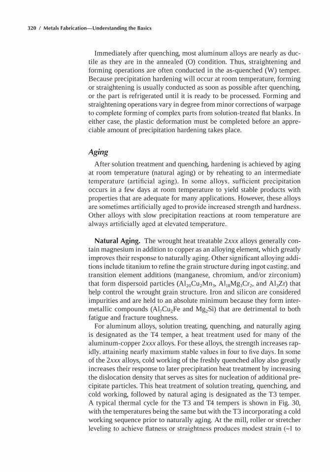
320 / Metals Fabrication—Understanding the Basics
immediately after quenching, most aluminum alloys are nearly as duc-tile as they are in the annealed (O) condition. thus, straightening and forming operations are often conducted in the as-quenched (W) temper. Because precipitation hardening will occur at room temperature, forming or straightening is usually conducted as soon as possible after quenching, or the part is refrigerated until it is ready to be processed. forming and straightening operations vary in degree from minor corrections of warpage to complete forming of complex parts from solution-treated flat blanks. In either case, the plastic deformation must be completed before an appre-ciable amount of precipitation hardening takes place.
Aging
after solution treatment and quenching, hardening is achieved by aging at room temperature (natural aging) or by reheating to an intermediate temperature (artificial aging). In some alloys, sufficient precipitation occurs in a few days at room temperature to yield stable products with properties that are adequate for many applications. however, these alloys are sometimes artificially aged to provide increased strength and hardness. Other alloys with slow precipitation reactions at room temperature are always artificially aged at elevated temperature.
Natural Aging. the wrought heat treatable 2xxx alloys generally con-tain magnesium in addition to copper as an alloying element, which greatly improves their response to naturally aging. Other significant alloying addi-tions include titanium to refine the grain structure during ingot casting, and transition element additions (manganese, chromium, and/or zirconium) that form dispersoid particles (al20Cu2mn3, al18mg3Cr2, and al3Zr) that help control the wrought grain structure. iron and silicon are considered impurities and are held to an absolute minimum because they form inter-metallic compounds (al7Cu2fe and mg2Si) that are detrimental to both fatigue and fracture toughness.
for aluminum alloys, solution treating, quenching, and naturally aging is designated as the t4 temper, a heat treatment used for many of the aluminum-copper 2xxx alloys. for these alloys, the strength increases rap-idly, attaining nearly maximum stable values in four to five days. In some of the 2xxx alloys, cold working of the freshly quenched alloy also greatly increases their response to later precipitation heat treatment by increasing the dislocation density that serves as sites for nucleation of additional pre-cipitate particles. this heat treatment of solution treating, quenching, and cold working, followed by natural aging is designated as the t3 temper. a typical thermal cycle for the t3 and t4 tempers is shown in fig. 30, with the temperatures being the same but with the t3 incorporating a cold working sequence prior to naturally aging. at the mill, roller or stretcher leveling to achieve flatness or straightness produces modest strain (~1 to
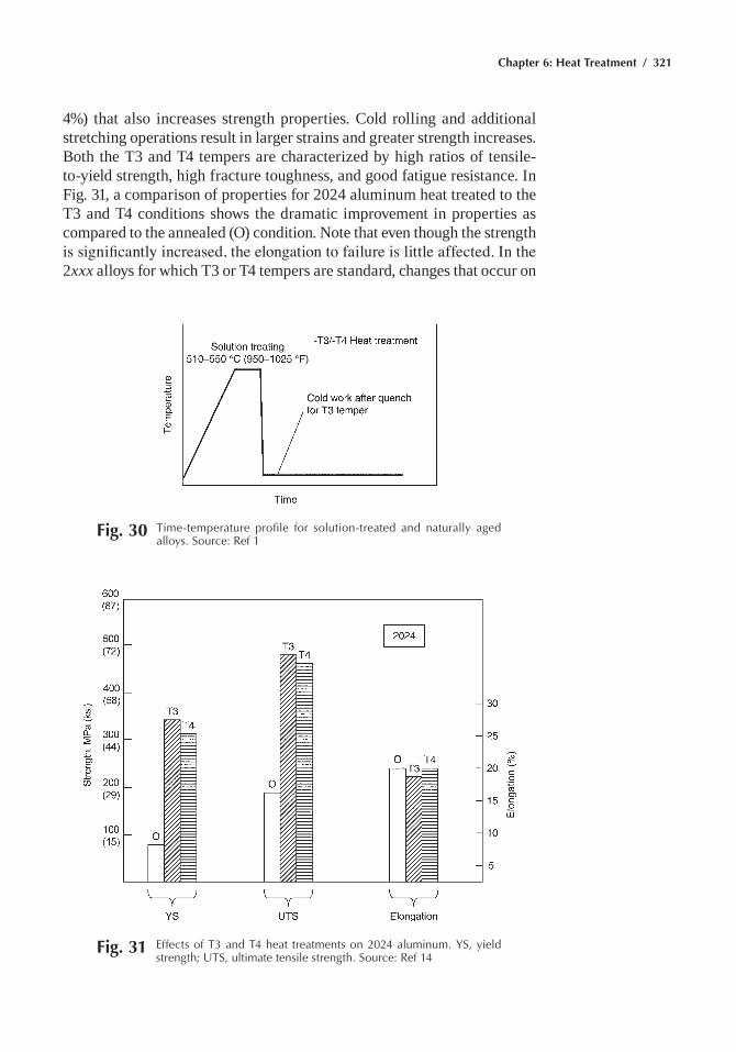
Chapter 6: Heat Treatment / 321
4%) that also increases strength properties. Cold rolling and additional stretching operations result in larger strains and greater strength increases. Both the t3 and t4 tempers are characterized by high ratios of tensile-to-yield strength, high fracture toughness, and good fatigue resistance. in fig. 31, a comparison of properties for 2024 aluminum heat treated to the t3 and t4 conditions shows the dramatic improvement in properties as compared to the annealed (O) condition. note that even though the strength is significantly increased, the elongation to failure is little affected. In the 2xxx alloys for which t3 or t4 tempers are standard, changes that occur on
Fig. 30 time-temperature profile for solution-treated and naturally aged alloys. Source: ref 1
Fig. 31 effects of t3 and t4 heat treatments on 2024 aluminum. YS, yield strength; UtS, ultimate tensile strength. Source: ref 14
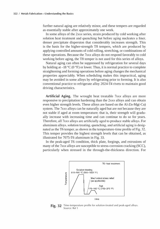
322 / Metals Fabrication—Understanding the Basics
further natural aging are relatively minor, and these tempers are regarded as essentially stable after approximately one week.
in some alloys of the 2xxx series, strain produced by cold working after solution heat treatment and quenching but before aging nucleates a finer, denser precipitate dispersion that considerably increases strength. this is the basis for the higher-strength t8 tempers, which are produced by applying controlled amounts of cold rolling, stretching, or combinations of these operations. Because the 7xxx alloys do not respond favorably to cold working before aging, the t8 temper is not used for this series of alloys.
natural aging can often be suppressed by refrigeration for several days by holding at –18 °C (0 °f) or lower. thus, it is normal practice to complete straightening and forming operations before aging changes the mechanical properties appreciably. When scheduling makes this impractical, aging may be avoided in some alloys by refrigerating prior to forming. it is also conventional practice to refrigerate alloy 2024-t4 rivets to maintain good driving characteristics.
Artificial Aging. the wrought heat treatable 7xxx alloys are more responsive to precipitation hardening than the 2xxx alloys and can obtain even higher strength levels. these alloys are based on the al-Zn-mg(-Cu) system. the 7xxx alloys can be naturally aged but are not because they are not stable if aged at room temperature; that is, their strength will gradu-ally increase with increasing time and can continue to do so for years. therefore, all 7xxx alloys are artificially aged to produce stable alloys. For aluminum alloys, solution treating, quenching, and artificial aging is desig-nated as the T6 temper, as shown in the temperature-time profile of Fig. 32. this temper provides the highest strength levels that can be obtained, as illustrated for 7075-t6 aluminum in fig. 33.
in the peak-aged t6 condition, thick plate, forgings, and extrusions of many of the 7xxx alloys are susceptible to stress-corrosion cracking (SCC), particularly when stressed in the through-the-thickness direction. for
Fig. 32 time-temperature profile for solution-treated and peak-aged alloys. Source: ref 1
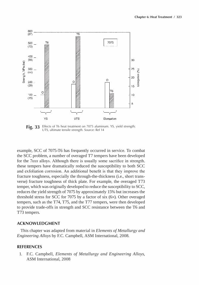
Chapter 6: Heat Treatment / 323
example, SCC of 7075-t6 has frequently occurred in service. to combat the SCC problem, a number of overaged t7 tempers have been developed for the 7xxx alloys. Although there is usually some sacrifice in strength, these tempers have dramatically reduced the susceptibility to both SCC and exfoliation corrosion. An additional benefit is that they improve the fracture toughness, especially the through-the-thickness (i.e., short trans-verse) fracture toughness of thick plate. for example, the overaged t73 temper, which was originally developed to reduce the susceptibility to SCC, reduces the yield strength of 7075 by approximately 15% but increases the threshold stress for SCC for 7075 by a factor of six (6¥). Other overaged tempers, such as the t74, t75, and the t77 tempers, were then developed to provide trade-offs in strength and SCC resistance between the t6 and t73 tempers.
ACKNOWLEDGMENT
this chapter was adapted from material in Elements of Metallurgy and Engineering Alloys by f.C. Campbell, aSm international, 2008.
REFERENCES
1. f.C. Campbell, Elements of Metallurgy and Engineering Alloys, aSm international, 2008
Fig. 33 effects of t6 heat treatment on 7075 aluminum. YS, yield strength; UtS, ultimate tensile strength. Source: ref 14
324 / Metals Fabrication—Understanding the Basics
2. t.B. massalski, h. Okamoto, p.r. Subramanian, and L. Kacprzak, Binary Alloy Phase Diagrams, 2nd ed., aSm international, 1990
3. h.e. Boyer, ed., Atlas of Isothermal Transformation and Cooling Transformation Diagrams, american Society for metals, 1977
4. a.G. Guy, Elements of Physical Metallurgy, 2nd ed., addison-Wesley publishing Company, 1959
5. B.L. Bramfitt and S.J. Lawrence, Metallography and Microstructures of Carbon and Low-alloy Steels, Metallography and Microstruc-tures, Vol 9, ASM Handbook, aSm international, 2004
6. Atlas of Isothermal and Continuous Cooling Diagrams, american Society for metals, 1977
7. t. ericsson, principles of heat treating of Steels, Heat Treating, Vol 4, ASM Handbook, aSm international, 1991
8. B.L. Bramfitt, Effects of Composition, Processing, and Structure on properties of irons and Steels, Materials Selection and Design, Vol 20, ASM Handbook, aSm international, 1997
9. m. Wisti and m. hingwe, tempering of Steel, Heat Treating, Vol 4, ASM Handbook, aSm international, 1991
10. G. Krauss, microstructures, processing, and properties of Steels, Properties and Selections: Irons, Steels, and High-Performance Alloys, Vol 1, ASM Handbook, aSm international, 1990
11. Localized heat treating, Metals Handbook Desk Edition, 2nd ed., aSm international, 1998
12. metallography and microstructures of Case-hardening Steel, Met-allography and Microstructures, Vol 9, ASM Handbook, aSm international, 2004
13. Case hardening of Steel, Metals Handbook Desk Edition, 2nd ed., aSm international, 1998
14. f.C. Campbell, Manufacturing Technology for Aerospace Structural Materials, Elsevier Scientific, 2006
SELECTED REFERENCES• J.R. Davis, Surface Hardening of Steels: Understanding the Basics,
aSm international, 2002• heat treating of nonferrous alloys, Metals Handbook Desk Edition,
2nd ed., aSm international, 1998• r. honeycombe and h.K.D.h. Bhadeshia, Steels—Microstructure and
Properties, 2nd ed., arnold, 1995• G. Krauss, Steels: Processing, Structure, and Performance, 3rd ed.,
aSm international, 2005
Copyright © 2013 ASM International®
All rights reservedwww.asminternational.org
Metals Fabrication—Understanding the BasicsF.C. Campbell, editor
Chapter 7Finishing and Coating
Surface finiSheS and coatingS are used in a variety of ways to improve the material properties of a component. for example, coat-ings that increase the hardness, strength, and toughness can improve the component wear, fatigue, and erosion properties, respectively. electrical properties in circuit design are dependent on surface-deposition processes. Similarly, environmental properties, such as resistance to aqueous corro-sion and high-temperature oxidation and sulfidation, can be improved by selective surface treatments.
Although the surface normally cannot be made totally independent from the bulk, the demands on surface and bulk properties are often quite differ-ent. For example, in the case of a turbine blade for a high-performance jet engine, the bulk of the material must have sufficient creep resistance and fatigue strength at the service temperature to provide an acceptably safe service life. On the other hand, the surface must possess sufficient resis-tance to oxidation and hot corrosion. in many instances, it is either more economical, or absolutely necessary, to select a material with the required bulk properties and then engineer the surface to create the required inter-face with the environment, rather than to find one material that has both the required bulk and surface properties.
Environmental Regulations
environmental protection regulations are often directly or indirectly related to finishing and coating processes. This is particularly true for solvent cleaning procedures, cadmium and chromium electroplating, chro-mate conversion coatings, and organic coatings containing high amounts of volatile organic compounds (solvents). the chemicals used for these processes may pose serious health and environmental hazards. for infor-mation about specific regulatory requirements, permitting conditions, and enforcement issues, the reader is advised to seek assistance from federal, state, and local regulatory agencies; consulting engineering firms; and law
326 / Metals Fabrication—Understanding the Basics
offices. Another valuable source of information can be found in the Sec-tion “Environmental Protection Issues” published in Surface Engineering, Volume 5, ASM Handbook.
Cleaning
cleaning processes used for removing soils and contaminants are varied, and their effectiveness depends on the requirements of the specific applica-tion. Because of the variety of available cleaning materials and the process step possibilities, the selection of a cleaning procedure greatly depends on the degree of cleanliness required and subsequent operations to be performed. Abrasive blasting produces the lowest degree of cleanliness. Solvent, solvent vapor degrease, emulsion soak, alkaline soak, alkaline electroclean, alkaline plus acid cleaning, and finally ultrasonics each pro-gressively produces a cleaner surface. understanding the mechanics of the cleaning action for particular processes can help guide the selection of an appropriate method.
Solvent cleaning, as the name implies, is the dissolution of contami-nants by an organic solvent. Typical solvents include trichloroethylene, methylene chloride, toluene, and benzene. The solvent can be applied by swabbing, tank immersion, spray or solid stream flushing, or vapor con-densation. Vapor degreasing is accomplished by immersing the work into a cloud of solvent vapor. The vapor condenses on the cooler work surface and dissolves the contaminants. Subsequent flushing with liquid solvent completes the cleaning process. Moderately elevated temperatures can be used to accelerate cleaning. One major drawback of solvent cleaning is the possibility of leaving some residues on the surface, often necessitating additional cleaning steps. Another more significant disadvantage is the environmental impact of solvent cleaning processes. in fact, much effort is being expended on replacing solvent-based processes with more envi-ronmentally acceptable aqueous-based processes.
Emulsion cleaning is a cleaning process that uses an organic solvent as the main active agent. The solvent is usually a hydrocarbon of distilled petroleum dispersed in water. the emulsion, which alone is potentially volatile, is suspended in a nonvolatile aqueous vehicle. Most emulsion cleaners include emulsifying agents, and some are aided by surfactants. Emulsion cleaners are generally used in situations where alkaline or acid cleaners are not applicable. The oil-in-water emulsion has tiny droplets of an organic (hydrocarbon) solvent dispersed throughout a water solu-tion. this is generally the type used in emulsion cleaning. the other is water-in-oil (natural petroleum), which has tiny droplets of a water solution dispersed throughout an oil. The oil-in-water type can easily be washed off with water and light detergent. The water-in-oil type leaves a greasy film that is much more difficult to remove.
Chapter 7: Finishing and Coating / 327
Alkaline cleaning is the mainstay of industrial cleaning and may employ both physical and chemical actions. Solid particles on the surface are generally assumed to be electrically attracted to the surface. During the cleaning process, these particles are surrounded by wetting agents that neutralize the electrical charge and allow them to be floated away, held in solution suspension indefinitely, or eventually settled out as sludge in the cleaning tank. A good water rinse is essential for good cleaning. The temperature of the water rinse may be hot, warm, or cold, but regardless of the temperature, the solution should be kept clean. Warm water is usually the best for rinsing. Cold rinses are less efficient than warm rinses, while hot rinses may promote the rapid formation of an oxide film commonly known as “flash rust.”
Electrolytic cleaning is a modification of alkaline cleaning in which an electrical current is imposed on the part to produce vigorous gassing on the surface that promotes the release of soils. electrocleaning can either be anodic or cathodic. Anodic cleaning is also called reverse cleaning, while cathodic cleaning is called direct cleaning. the release of oxygen gas under anodic cleaning or hydrogen gas under cathodic cleaning in the form of tiny bubbles from the work surface greatly facilitates lifting and removing of surface soils.
Abrasive cleaning uses small sharp particles propelled by an air stream or water jet to impinge on the surface, removing contaminants by the resulting impact force. A wide variety of abrasive media in many sizes is available to meet specific needs. Abrasive cleaning is often pre-ferred for removing heavy scale and paint, especially on large, otherwise inaccessible areas. Abrasive cleaning is also frequently the only allow-able cleaning method for steels sensitive to hydrogen embrittlement. This method of cleaning is also used to prepare metals, such as stainless steel and titanium, for painting to help produce a mechanical lock for adhesion, because conversion coatings cannot be applied easily to these metals.
Acid cleaning is more often used in conjunction with other steps than by itself. Acids have the ability to dissolve oxides, which are usually insoluble in other solutions. Straight mineral acids, such as hydrochloric, sulfuric, and nitric acids, are used for most acid cleaning applications, but organic acids, such as citric, oxalic, acetic, tartaric, and gluconic acids, occupy an important place in acid cleaning because of their chelating capability.
Phosphoric Acid Etching. Phosphoric acid is often used as an etchant for nonferrous metals (such as copper, brass, aluminum, and zinc) to enhance paint adhesion. A detergent-bearing iron phosphating solution is often ideal for this sort of combined cleaning and etching approach.
Molten salt bath cleaning is very effective for removing many soils, especially paints and heavy scale. however, the very high operating tem-
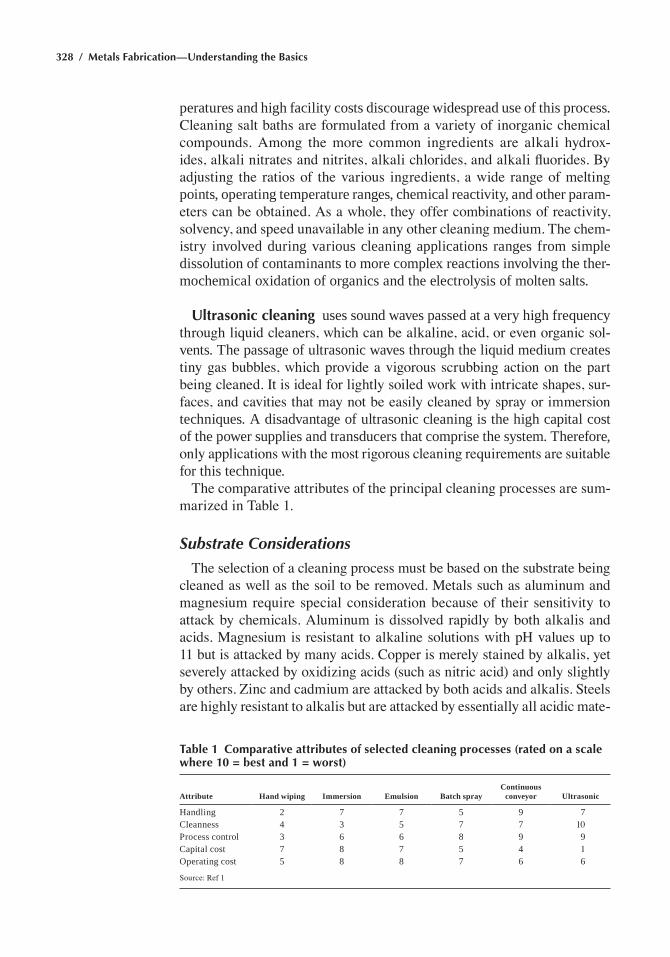
328 / Metals Fabrication—Understanding the Basics
peratures and high facility costs discourage widespread use of this process. Cleaning salt baths are formulated from a variety of inorganic chemical compounds. Among the more common ingredients are alkali hydrox-ides, alkali nitrates and nitrites, alkali chlorides, and alkali fluorides. By adjusting the ratios of the various ingredients, a wide range of melting points, operating temperature ranges, chemical reactivity, and other param-eters can be obtained. As a whole, they offer combinations of reactivity, solvency, and speed unavailable in any other cleaning medium. The chem-istry involved during various cleaning applications ranges from simple dissolution of contaminants to more complex reactions involving the ther-mochemical oxidation of organics and the electrolysis of molten salts.
Ultrasonic cleaning uses sound waves passed at a very high frequency through liquid cleaners, which can be alkaline, acid, or even organic sol-vents. the passage of ultrasonic waves through the liquid medium creates tiny gas bubbles, which provide a vigorous scrubbing action on the part being cleaned. It is ideal for lightly soiled work with intricate shapes, sur-faces, and cavities that may not be easily cleaned by spray or immersion techniques. a disadvantage of ultrasonic cleaning is the high capital cost of the power supplies and transducers that comprise the system. therefore, only applications with the most rigorous cleaning requirements are suitable for this technique.
The comparative attributes of the principal cleaning processes are sum-marized in Table 1.
Substrate Considerations
The selection of a cleaning process must be based on the substrate being cleaned as well as the soil to be removed. Metals such as aluminum and magnesium require special consideration because of their sensitivity to attack by chemicals. Aluminum is dissolved rapidly by both alkalis and acids. Magnesium is resistant to alkaline solutions with pH values up to 11 but is attacked by many acids. Copper is merely stained by alkalis, yet severely attacked by oxidizing acids (such as nitric acid) and only slightly by others. Zinc and cadmium are attacked by both acids and alkalis. Steels are highly resistant to alkalis but are attacked by essentially all acidic mate-
Table 1 Comparative attributes of selected cleaning processes (rated on a scale where 10 = best and 1 = worst)
Attribute Hand wiping Immersion Emulsion Batch sprayContinuous
conveyor Ultrasonic
handling 2 7 7 5 9 7cleanness 4 3 5 7 7 10Process control 3 6 6 8 9 9capital cost 7 8 7 5 4 1operating cost 5 8 8 7 6 6
Source: Ref 1
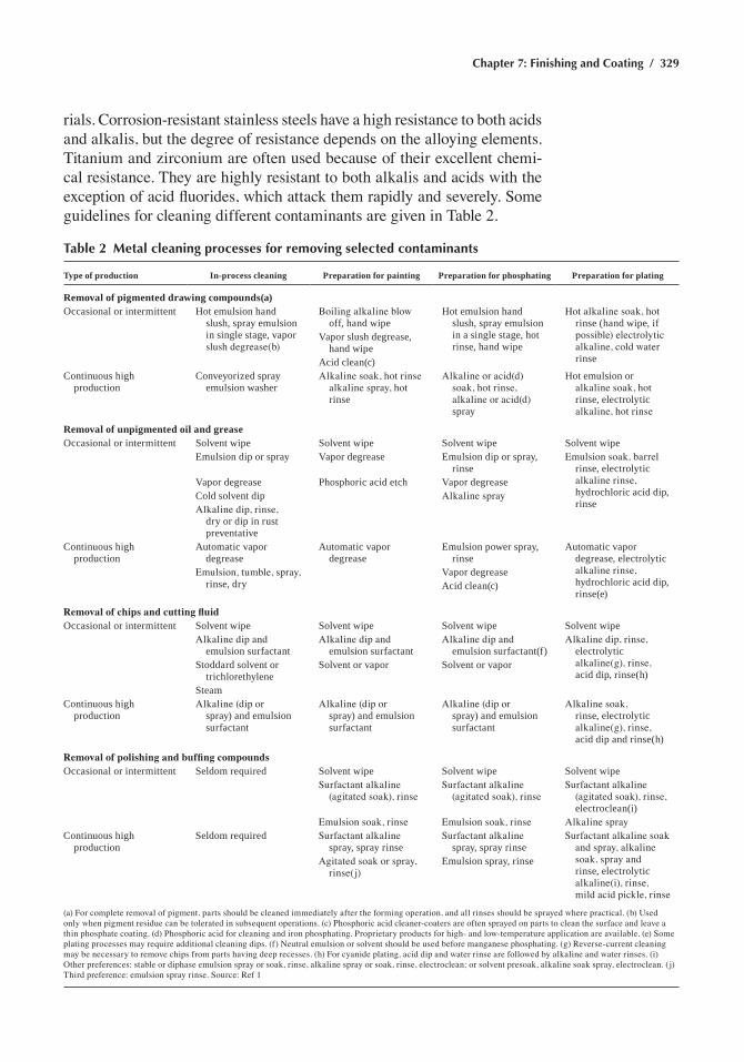
Chapter 7: Finishing and Coating / 329
rials. Corrosion-resistant stainless steels have a high resistance to both acids and alkalis, but the degree of resistance depends on the alloying elements. Titanium and zirconium are often used because of their excellent chemi-cal resistance. They are highly resistant to both alkalis and acids with the exception of acid fluorides, which attack them rapidly and severely. Some guidelines for cleaning different contaminants are given in Table 2.
Table 2 Metal cleaning processes for removing selected contaminants
Type of production In-process cleaning Preparation for painting Preparation for phosphating Preparation for plating
Removal of pigmented drawing compounds(a)occasional or intermittent hot emulsion hand
slush, spray emulsion in single stage, vapor slush degrease(b)
Boiling alkaline blow off, hand wipe
hot emulsion hand slush, spray emulsion in a single stage, hot rinse, hand wipe
Hot alkaline soak, hot rinse (hand wipe, if possible) electrolytic alkaline, cold water rinse
Vapor slush degrease, hand wipe
acid clean(c)continuous high
productionconveyorized spray
emulsion washerAlkaline soak, hot rinse
alkaline spray, hot rinse
Alkaline or acid(d) soak, hot rinse, alkaline or acid(d) spray
hot emulsion or alkaline soak, hot rinse, electrolytic alkaline, hot rinse
Removal of unpigmented oil and greaseoccasional or intermittent Solvent wipe Solvent wipe Solvent wipe Solvent wipe
emulsion dip or spray Vapor degrease emulsion dip or spray, rinse
Emulsion soak, barrel rinse, electrolytic alkaline rinse, hydrochloric acid dip, rinse
Vapor degrease Phosphoric acid etch Vapor degreasecold solvent dip Alkaline sprayAlkaline dip, rinse,
dry or dip in rust preventative
continuous high production
automatic vapor degrease
automatic vapor degrease
emulsion power spray, rinse
automatic vapor degrease, electrolytic alkaline rinse, hydrochloric acid dip, rinse(e)
Emulsion, tumble, spray, rinse, dry
Vapor degreaseacid clean(c)
Removal of chips and cutting fluidoccasional or intermittent Solvent wipe Solvent wipe Solvent wipe Solvent wipe
Alkaline dip and emulsion surfactant
Alkaline dip and emulsion surfactant
Alkaline dip and emulsion surfactant(f)
Alkaline dip, rinse, electrolytic alkaline(g), rinse, acid dip, rinse(h)
Stoddard solvent or trichlorethylene
Solvent or vapor Solvent or vapor
Steamcontinuous high
productionAlkaline (dip or
spray) and emulsion surfactant
Alkaline (dip or spray) and emulsion surfactant
Alkaline (dip or spray) and emulsion surfactant
Alkaline soak, rinse, electrolytic alkaline(g), rinse, acid dip and rinse(h)
Removal of polishing and buffing compoundsoccasional or intermittent Seldom required Solvent wipe Solvent wipe Solvent wipe
Surfactant alkaline (agitated soak), rinse
Surfactant alkaline (agitated soak), rinse
Surfactant alkaline (agitated soak), rinse, electroclean(i)
Emulsion soak, rinse Emulsion soak, rinse Alkaline spraycontinuous high
productionSeldom required Surfactant alkaline
spray, spray rinseSurfactant alkaline
spray, spray rinseSurfactant alkaline soak
and spray, alkaline soak, spray and rinse, electrolytic alkaline(i), rinse, mild acid pickle, rinse
Agitated soak or spray, rinse(j)
emulsion spray, rinse
(a) For complete removal of pigment, parts should be cleaned immediately after the forming operation, and all rinses should be sprayed where practical. (b) Used only when pigment residue can be tolerated in subsequent operations. (c) Phosphoric acid cleaner-coaters are often sprayed on parts to clean the surface and leave a thin phosphate coating. (d) Phosphoric acid for cleaning and iron phosphating. Proprietary products for high- and low-temperature application are available. (e) Some plating processes may require additional cleaning dips. (f) Neutral emulsion or solvent should be used before manganese phosphating. (g) Reverse-current cleaning may be necessary to remove chips from parts having deep recesses. (h) For cyanide plating, acid dip and water rinse are followed by alkaline and water rinses. (i) Other preferences: stable or diphase emulsion spray or soak, rinse, alkaline spray or soak, rinse, electroclean; or solvent presoak, alkaline soak spray, electroclean. (j)Third preference: emulsion spray rinse. Source: Ref 1
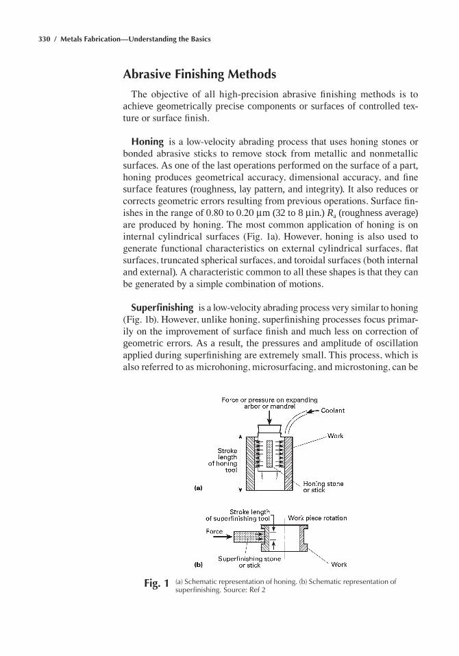
330 / Metals Fabrication—Understanding the Basics
Abrasive Finishing Methods
The objective of all high-precision abrasive finishing methods is to achieve geometrically precise components or surfaces of controlled tex-ture or surface finish.
Honing is a low-velocity abrading process that uses honing stones or bonded abrasive sticks to remove stock from metallic and nonmetallic surfaces. as one of the last operations performed on the surface of a part, honing produces geometrical accuracy, dimensional accuracy, and fine surface features (roughness, lay pattern, and integrity). it also reduces or corrects geometric errors resulting from previous operations. Surface fin-ishes in the range of 0.80 to 0.20 mm (32 to 8 min.) Ra (roughness average) are produced by honing. The most common application of honing is on internal cylindrical surfaces (Fig. 1a). However, honing is also used to generate functional characteristics on external cylindrical surfaces, flat surfaces, truncated spherical surfaces, and toroidal surfaces (both internal and external). a characteristic common to all these shapes is that they can be generated by a simple combination of motions.
Superfinishing is a low-velocity abrading process very similar to honing (Fig. 1b). However, unlike honing, superfinishing processes focus primar-ily on the improvement of surface finish and much less on correction of geometric errors. as a result, the pressures and amplitude of oscillation applied during superfinishing are extremely small. This process, which is also referred to as microhoning, microsurfacing, and microstoning, can be
Fig. 1 (a) Schematic representation of honing. (b) Schematic representation of superfinishing. Source: ref 2
Chapter 7: Finishing and Coating / 331
cost effective in producing surface finishes of the order of 0.10 to 0.050 mm (4 to 2 min.) Ra.
Polishing and Buffing
Polishing and buffing improve edge and surface conditions for decora-tive or functional purposes. These techniques are abrading operations, although some plastic working of surfaces may occur, particularly in buff-ing. Polishing is the use of abrasives that are firmly attached to a flexible backing, such as a wheel or belt, while buffing is the use of abrasives or abrasive compounds that adhere loosely to a flexible backing, such as a wheel. Polishing operations usually follow grinding and precede buffing. In general, polishing permits more aggressive abrading action than buff-ing. Polishing has a greater capability to modify the shape of a component and remove scratches, while buffing produces finer finishes. Polishing and buffing processes are used on most metals and many nonmetals for refining edges and surfaces of castings, forgings, machined and stamped components, and molded and fabricated parts. Traditionally, these pro-cesses have been considered a means of developing attractive, decorative surfaces and generating suitable preplate and prepaint surfaces.
Polishing
Polishing is used to remove or smooth grinding lines, scratches, pits, mold marks, parting lines, tool marks, stretcher strains, and surface defects that adversely affect part appearance or function. Polishing is performed with either a wheel or belt to which an abrasive is bonded. The process causes some plastic working of the surface as metal is removed. The result-ing polished surface usually has a finish of 0.4 mm (16 min.) Ra or less.
Aluminum oxide and silicon carbide are the most widely used synthetic abrasives. They are harder, more uniform, longer lasting, and easier to control than natural abrasives such as emery or corundum. Because alumi-num oxide grains are very angular and have excellent bonding properties, they are particularly useful in polishing tougher metals, such as alloy steels, high-speed steels, and malleable and wrought iron. Silicon carbide is harder than aluminum oxide, and it fractures easily, providing new cut-ting surfaces that extend the useful life of the abrasive. Silicon carbide is usually used in polishing low-strength metals, such as aluminum and cop-per. It is also used to polish hard, brittle materials, such as carbide tools, high-strength steels, and chilled and gray irons.
Polishing wheels were the original abrading product for finishing pur-poses. Although still used, they have been largely replaced by abrasive belts, which offer better performance, greater consistency, and reduced labor. Polishing wheels are disks made of materials such as cloth and
332 / Metals Fabrication—Understanding the Basics
leather, sewed and/or glued together. the periphery is coated with alter-nating layers of adhesive and abrasive grain to the desired thickness. The technique and care required to make the polishing wheel can be eliminated by using polishing belts, but in certain applications, polishing wheels can-not be replaced. An obscure or confined area, such as an automobile wheel that is to be plated, is readily polished with a polishing wheel. The cutlery industry and the jewelry industry use polishing wheels for special effects, in some areas that are difficult to reach, and where the polished finish must be confined to certain areas.
Endless cloth belts, precoated with abrasives, are widely used in pol-ishing operations. in comparison to polishing wheels, they offer these advantages:
• Closer control of surface finish• Smaller inventory of polishing accessories• Less heat generation in polishing because of the larger surface area
of belts• elimination of the need for costly, temperature-controlled wheel setup
rooms, and for the care, preparation, and upkeep of wheels, adhesive, and abrasives
• More uniform finish than can be achieved by polishing wheels• Less labor, because belts offer more consistent performance and no
labor is required to recoat contact wheels• Greater flexibility than polishing wheels because of various densities
of contact roll or wheels that can make belts hard or soft. In some applications, the slack of the belt can be used effectively.
Nylon wheels are flexible, resilient, and made of abrasive-impregnated nonwoven nylon or another synthetic fiber. The abrasive is dispersed evenly throughout these materials, so that wheel performance remains substan-tially constant despite wheel wear. In many cases these wheels can be shaped to conform to curved, irregular surfaces. they are water resistant and range from 25 to 2000 mm (1 to 80 in.) in width and from 25 to 400 mm (1 to 16 in.) in diameter. A wide variety of densities and grit sizes are available. Nylon wheels can be used wet or dry, or with grinding lubricants, such as waxes, oils, or greases.
nylon wheels are especially useful for imposing uniform scratch pat-terns or satin finishes on nonferrous metals, plastics, and wood. They are recommended for various types of blending, as well as for the removal of light surface stains, scale, rust, or old coatings. They are not suitable for the removal of large amounts of stock, deep defects, or surface irregularities but are effective in removing burrs and radiusing sharp edges. They oper-ate with speeds ranging from 3 to 33 m/s (500 to 6500 sfm), depending on the specific wheel and application. When nylon wheels are used to finish
Chapter 7: Finishing and Coating / 333
flat sheet stock, wheel oscillation is recommended to attain a uniform fin-ish, free of streaks. An oscillation of approximately 200 cycles/min with 10 mm (0.375 in.) amplitude gives good results in a variety of applications. Greater amplitudes, up to 50 mm (2 in.), can be used on steel or other hard metals, but on softer metals, amplitudes greater that 13 mm (0.5in.) are likely to create “snake marks.”
Buffing
Buffing produces smooth, reflective surfaces. It is the rearrangement and refinement of component scratch and has the ability to level surfaces where the scratch is visible only under high magnification. Buffing is accom-plished by bringing a workpiece into direct contact with a revolving cloth or buffing wheel that is charged with a suitable compound. Depending on the type of wheel and compound, substantial stock can be removed, radii can be generated consistently, and smooth, bright, and lustrous surfaces can be produced with precision.
Hard buffing is used to cut down or smooth the surface of a material that may or may not have been polished previously. Buffs used for hard buffing are usually made of cloth with a high thread count. The density of the thread count varies with the requirements of the job. Because hard buffing entails both a cutting action and a plowing action, an aggressive compound is generally used.
Color buffing refines a surface to a very high finish and produces a lustrous, scratch-free condition. Any marks or scratches left on a surface after hard buffing can be removed by color buffing. Color buffs are always softer than those used for hard buffing and are made of cloths with a lower thread count. Color buffing compounds must produce a high finish and permit the buffing wheel to shed or throw off the small particles of metal and compound that build up during buffing. If a compound does not provide this shedding action, the buildup of particles forms a solid cutting head, requiring the buff to be raked or cleaned frequently.
Most buffing compounds consist of an abrasive that is immersed in a binder carrier. The abrasive serves as the principal cutting medium. The binder provides lubrication, prevents overheating of the work, and firmly cements the abrasive to the wheel face. Binders must not chemically etch, corrode, or mark the metal surface.
Abrasive grains generally used with all finishing compounds include:
• Tripoli and/or silica for finishing of most nonferrous materials and plastics
• Fused aluminum oxide for finishing of ferrous products• Calcined alumina for finishing of ferrous and nonferrous materials
334 / Metals Fabrication—Understanding the Basics
• Red rouge (red iron oxide powder) for high coloring or finishing of brass products
• Green chromium oxide flours for high coloring or finishing of nonfer-rous materials and stainless steel, and for finishing of plastic products
• Silicon carbide or diamond for finishing of ceramics and hard materi-als such as carbides
all of these materials are used with fatty acids and wetting agents in liquid form and are made to suit all of the cleaning processes that are necessary prior to any plating or anodizing operation. the action of any individual compound can be altered by increasing or decreasing the par-ticle size of the abrasive or by varying the amount and types of lubricant used in the binder. If a more intense cutting action is required, the particle size of the same abrasive or the quantity of binder can be increased. Mod-ern compounds use water-soluble binders. The lubricant used in the binder generally has a mineral, animal, or vegetable base.
Lapping
Lapping is a low-velocity abrasion process that removes controlled, very small amounts of material. It is accomplished with loose abrasive grains (usually retained in a viscous or liquid media, called the vehicle) held between a lapping plate (usually made of cast iron or steel hardened to 60 HRC) and the work surface. Lapping is generally a final finishing opera-tion that results in four major refinements in the workpiece: extremely accurate dimensions, correction of minor shape imperfections, surface finish refinement, and close fit between mating surfaces. The life of moving parts that are subject to wear can be greatly increased by eliminating the minute hills and valleys on workpiece surfaces and creating a maximum percentage of bearing area. Besides developing a workpiece that meets the surface finish requirements and is geometrically and dimensionally cor-rect, there is no distortion, because lapping procedures do not require the use of magnetic chucks or other holding or clamping devices.
in normal lapping operations, less heat is generated than in most other finishing operations, thus minimizing the possibility of rehardened and decarburized areas on hardened or heat treated parts. When both sides of a flat piece are lapped in the same operation, extreme accuracy in flatness and parallelism can be accomplished, and by removing the same amount of stock from both sides of the part simultaneously, any inherent stresses in the piece are equally relieved.
Silicon carbide and fused aluminum oxide are the abrasives most widely used for lapping. Silicon carbide is used for lapping hardened steel or cast iron. fused alumina is used for lapping soft steels or nonferrous metals. Diamond and natural abrasives are also sometimes used. Surface finishes in the range of 0.40 to 0.05 mm (16 to 2 min.) Ra are produced by lapping.
Chapter 7: Finishing and Coating / 335
Electropolishing
Electropolishing is a nonabrasive electrochemical process for remov-ing metal. Etching, deburring, smoothing, coloring, and machining are typical electropolishing processes. the removal of metal is done anodi-cally in acid and alkaline solutions. The most widely used electropolishing solutions contain one or more of the concentrated inorganic acids—sul-furic, phosphoric, and chromic. Sometimes, an inorganic acid, such as hydrofluoric or hydrochloric acid, or an organic acid, such as acetic, citric, tartaric, or glycolic acid, can be used with one or more of the concentrated inorganic acids mentioned above.
Electropolish is used primarily for obtaining mirrorlike surfaces from highly smooth initial surfaces. A final finish of less than 0.05 mm (2 min.) can be obtained if the initial surface roughness (root mean square) does not exceed 0.18 to 0.20 mm (7 to 8 min.). electropolishing was primar-ily developed for polishing metallurgical specimens and for polishing of irregular shapes that were difficult to buff. Now electropolishing is used for polishing stainless steel sheets and parts.
Mass Finishing
Mass finishing normally involves loading the parts into a container together with some abrasive medium, water, and compound. A mechani-cal action is applied to the container to cause the medium to rub against the surfaces, edges, and corners of the parts, or to cause the parts to rub against each other, or both. This action may deburr, generate edge and corner radii, clean the parts by removing rust and scale, and modify the surface stress. The basic mass finishing processes include:
• Barrel finishing• Vibratory finishing• Spindle finishing• Centrifugal disk finishing• Centrifugal barrel finishing
Barrel Finishing. The rotary barrel, or tumbling barrel, uses the sliding movement of an upper layer of workload in the barrel, as shown in Fig. 2. The barrel is normally loaded approximately 60% full with a mixture of parts, medium, compound, and water. As the barrel rotates, the load moves upward to a turnover point; then the force of gravity overcomes the tendency of the mass to stick together, and the top layer slides toward the lower area of the barrel.
Vibratory Finishing. A vibratory finishing machine is an open-topped tub or bowl mounted on springs, usually lined with polyurethane. Parts
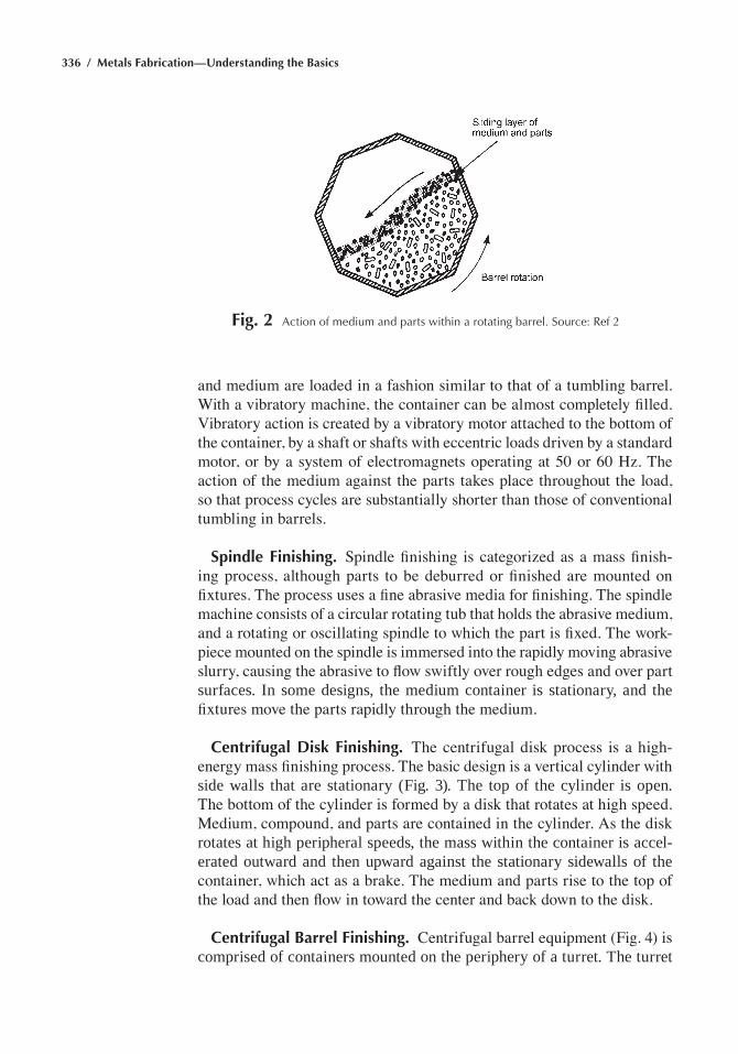
336 / Metals Fabrication—Understanding the Basics
and medium are loaded in a fashion similar to that of a tumbling barrel. With a vibratory machine, the container can be almost completely filled. Vibratory action is created by a vibratory motor attached to the bottom of the container, by a shaft or shafts with eccentric loads driven by a standard motor, or by a system of electromagnets operating at 50 or 60 Hz. The action of the medium against the parts takes place throughout the load, so that process cycles are substantially shorter than those of conventional tumbling in barrels.
Spindle Finishing. Spindle finishing is categorized as a mass finish-ing process, although parts to be deburred or finished are mounted on fixtures. The process uses a fine abrasive media for finishing. The spindle machine consists of a circular rotating tub that holds the abrasive medium, and a rotating or oscillating spindle to which the part is fixed. The work-piece mounted on the spindle is immersed into the rapidly moving abrasive slurry, causing the abrasive to flow swiftly over rough edges and over part surfaces. in some designs, the medium container is stationary, and the fixtures move the parts rapidly through the medium.
Centrifugal Disk Finishing. The centrifugal disk process is a high-energy mass finishing process. The basic design is a vertical cylinder with side walls that are stationary (fig. 3). the top of the cylinder is open. The bottom of the cylinder is formed by a disk that rotates at high speed. Medium, compound, and parts are contained in the cylinder. As the disk rotates at high peripheral speeds, the mass within the container is accel-erated outward and then upward against the stationary sidewalls of the container, which act as a brake. The medium and parts rise to the top of the load and then flow in toward the center and back down to the disk.
Centrifugal Barrel Finishing. Centrifugal barrel equipment (Fig. 4) is comprised of containers mounted on the periphery of a turret. the turret
Fig. 2 action of medium and parts within a rotating barrel. Source: ref 2
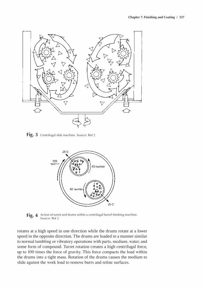
Chapter 7: Finishing and Coating / 337
Fig. 3 Centrifugal disk machine. Source: ref 2
Fig. 4 action of turret and drums within a centrifugal barrel finishing machine. Source: ref 2
rotates at a high speed in one direction while the drums rotate at a lower speed in the opposite direction. the drums are loaded in a manner similar to normal tumbling or vibratory operations with parts, medium, water, and some form of compound. turret rotation creates a high centrifugal force, up to 100 times the force of gravity. This force compacts the load within the drums into a tight mass. rotation of the drums causes the medium to slide against the work load to remove burrs and refine surfaces.
338 / Metals Fabrication—Understanding the Basics
Rust-Preventive Compounds
Rust-preventive compounds are removable coatings used to protect iron and steel surfaces against corrosive environments during fabrication, stor-age, or use. Rust-preventive compounds can be divided into seven general categories:
• Petrolatum compounds have a greaselike consistency. They provide protection by the inclusion of effective corrosion inhibitors and by the continuous physical barrier presented to corrodents by the film.
• Oil compounds are similar to lubricating oils but contain active rust inhibitors and corrosion inhibitors in amounts that afford effective protection under various conditions of exposure.
• Hard dry-film compounds establish a film either by solvent evaporation or by chemical reaction after application. The coatings generally are thin but fairly hard, being similar in appearance to varnish.
• Solvent-cutback, petroleum-base compounds are deposited as residual coatings through solvent evaporation. this class encompasses mate-rials ranging from those that leave a thin, transparent film to those forming a relatively heavy asphaltic or bitumastic film that hardens sufficiently to form an impervious barrier.
• Emulsion compounds rely on the polarity and preferential attraction of emulsifiers or inhibitors to metal surfaces for protection of the surfaces after the water phase has evaporated.
• Water-displacing polar compounds contain preferential wetting agents that have an affinity for metal surfaces.
• Fingerprint removers and neutralizers are low-viscosity compounds containing suitable solvents to dissolve, suppress, and neutralize acids, salts, and residues from handling and from other sources of surface contamination. they are used for in-process or other short-term pro-tection, or as pretreatments for longer-term protection.
Rust preventives are applied by spraying, fogging, dipping, flowing, slushing, brushing, and wiping. The method used is determined by the type of preventive and by the quantity, size, complexity, and surface finish of the parts to be coated. The equipment and methods of application used are similar to those used in painting.
Phosphate Conversion Coatings
Phosphate coating is the treatment of iron, steel, galvanized steel, or aluminum with a dilute solution of phosphoric acid and other chemicals in which the surface of the metal, reacting chemically with the phosphoric acid medium, is converted to an integral, mildly protective layer of insolu-ble crystalline phosphate. Phosphate coatings range in thickness from less
Chapter 7: Finishing and Coating / 339
than 3 to 50 mm (0.1 to 2 mils). Coating weight (grams per square meter of coated area), rather than coating thickness, has been adopted as the basis for expressing the amount of coating deposited. three principal types of phosphate coatings are in general use: zinc, iron, and manganese. a fourth type, lead phosphate, which was more recently introduced, is operated at ambient temperatures.
The application of a phosphate coating as a base for subsequent painting normally comprises five successive operations: cleaning, rinsing, phos-phating, rinsing, and chromic acid rinsing. Some of these operations can be omitted or combined, such as cleaning and coating in one operation. Additional operations may be required, depending on the surface condition of the parts to be phosphated or on the function of the phosphate coating. Phosphate coatings can be applied to a surface by either immersion or spraying, or by a combination of immersion and spraying.
Chromate Conversion Coatings
chromate conversion coatings are formed on metal surfaces as a result of the chemical attack that occurs when a metal is immersed in or sprayed with an aqueous solution of chromic acid, chromium salts such as sodium or potassium chromate or dichromate, hydrofluoric acid or hydrofluoric acid salts, phosphoric acid, or other mineral acids. The chemical attack causes dissolution of some surface metal and formation of a protective film containing complex chromium compounds. chromate conversion coatings are primarily applied to enhance bare or painted corrosion resistance, to improve the adhesion of paint or other organic finishes, and to provide the metallic surface with a decorative finish. Chromating processes are used to finish aluminum, zinc, steel, magnesium, cadmium, copper, tin, nickel, silver, and other substrates. Chromate conversion coatings are widely used in the aerospace industry.
chromate treatments are of two types: those that are complete in them-selves and deposit substantial chromate films on the substrate metal, and those that are used to seal or supplement oxide, phosphate, or other types of nonmetallic protective coatings. two chromate treatments for aluminum are complete in themselves: chromium chromate and chromium phosphate. to form the chromium phosphate coating, phosphoric acid or phosphoric acid salts are required in addition to chromic and hydrofluoric acids or their corresponding salts.
Electroplating Processes
electroplating is an electrolytic process in which metal ions in an elec-trolyte solution are deposited onto a cathode workpiece. The setup is shown in Fig. 5. The anode is generally made of the metal being plated and serves as the source of the plate metal. direct current from an external power sup-
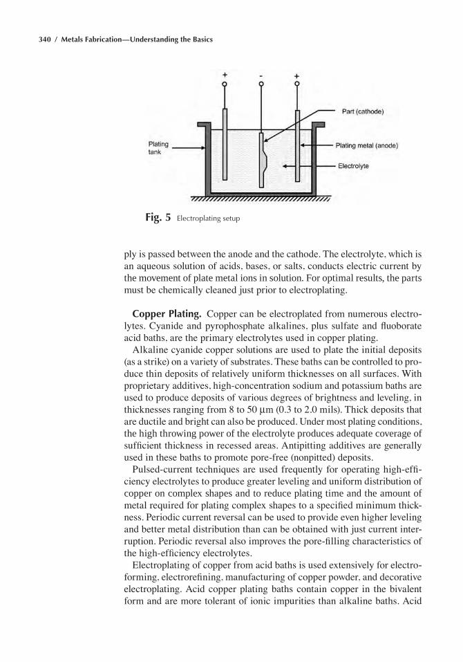
340 / Metals Fabrication—Understanding the Basics
ply is passed between the anode and the cathode. The electrolyte, which is an aqueous solution of acids, bases, or salts, conducts electric current by the movement of plate metal ions in solution. for optimal results, the parts must be chemically cleaned just prior to electroplating.
Copper Plating. Copper can be electroplated from numerous electro-lytes. Cyanide and pyrophosphate alkalines, plus sulfate and fluoborate acid baths, are the primary electrolytes used in copper plating.
Alkaline cyanide copper solutions are used to plate the initial deposits (as a strike) on a variety of substrates. These baths can be controlled to pro-duce thin deposits of relatively uniform thicknesses on all surfaces. With proprietary additives, high-concentration sodium and potassium baths are used to produce deposits of various degrees of brightness and leveling, in thicknesses ranging from 8 to 50 mm (0.3 to 2.0 mils). Thick deposits that are ductile and bright can also be produced. Under most plating conditions, the high throwing power of the electrolyte produces adequate coverage of sufficient thickness in recessed areas. Antipitting additives are generally used in these baths to promote pore-free (nonpitted) deposits.
Pulsed-current techniques are used frequently for operating high-effi-ciency electrolytes to produce greater leveling and uniform distribution of copper on complex shapes and to reduce plating time and the amount of metal required for plating complex shapes to a specified minimum thick-ness. Periodic current reversal can be used to provide even higher leveling and better metal distribution than can be obtained with just current inter-ruption. Periodic reversal also improves the pore-filling characteristics of the high-efficiency electrolytes.
Electroplating of copper from acid baths is used extensively for electro-forming, electrorefining, manufacturing of copper powder, and decorative electroplating. Acid copper plating baths contain copper in the bivalent form and are more tolerant of ionic impurities than alkaline baths. Acid
Fig. 5 electroplating setup
Chapter 7: Finishing and Coating / 341
baths have excellent microthrowing power, which can be effective in seal-ing porous die castings.
Industrial hard chromium plating is produced by electroplating from a solution containing chromic acid (cro3) and a catalytic anion in proper proportion. chromic acid is the source of metal in hard chromium plating baths. However, a chromic acid solution does not deposit chromium unless a definite amount of catalyst is present. If there is either too much or too little catalyst, no chromium metal is deposited. catalysts that have proved successful are acid anions, the first of which to be used was sulfate. The plating produced is extremely hard and corrosion resistant.
The process is used for rebuilding mismachined or worn parts, for auto-motive valve stems, piston rings, shock rods, MacPherson struts, the bores of diesel and aircraft cylinders, and for hydraulic shafts. hard chromium plating is also known as industrial, functional, or engineering chromium plating.
the principal uses of hard chromium plating include:
• Wear Resistance. extensive performance data indicates the effective-ness of chromium plate in reducing wear of piston rings due to scuffing and abrasion. The average life of a chromium-plated ring is approxi-mately five times that of an unplated ring made of the same base metal. Piston rings for most engines have a chromium plate thickness of 100 to 200 mm (4 to 8 mils) on the wearing face, although thicknesses up to 250 mm (10 mils) are specified for some heavy-duty engines.
• Tooling Applications. Various types of tools are plated with chromium for one or more of the following reasons: to minimize wear, prevent seizing and galling, reduce friction, and prevent or minimize corro-sion. Steel or beryllium copper dies for plastic moldings are usually plated with chromium. Worn gages can be salvaged by being built up with hard chromium plate. also, chromium plate provides steel gages with good protection against rusting in normal exposure and handling. Deep-drawing tools are often plated with chromium, in thickness up to 100 mm (4 mils), for improvement of tool performance or building up of worn areas, or for both reasons.
Decorative chromium plating is differentiated from hard chromium plating by thickness and by the type of undercoating used. Decorative chro-mium coatings are very thin, usually not exceeding an average thickness of 1.3 mm (5 mils). decorative chromium is applied over an undercoating, such as nickel or copper plus nickel, which imparts a bright, semibright, or satin cosmetic appearance. the choice of undercoatings, as well as the type of chromium applied, can also provide corrosion protection. Most deco-rative chromium coatings have been applied using hexavalent chromium processes that are based on chromic anhydride. However, since 1975, tri-
342 / Metals Fabrication—Understanding the Basics
valent chromium processes have become available commercially. They are increasing in importance because of their increased throwing and covering powers and because they offer environmental advantages.
Nickel Plating. The nickel plating process is used extensively for deco-rative, engineering, and electroforming purposes because the appearance and other properties of electroplated nickel can be varied over wide ranges by controlling the composition and the operating parameters of the plating solution. Decorative applications account for approximately 80% of nickel plating, while the remaining 20% is consumed for engineering and electro-forming purposes. Single-layer bright nickel coatings are suitable for use in mildly corrosive service using a nickel thickness of 10 to 20 mm (0.4 to 0.8 mils). For severe and very severe conditions of exposure, especially where long-time resistance to corrosion is required, multilayer nickel coat-ings with microdiscontinuous chromium are used. the principal types are double- and triple-layer coatings.
Cadmium plating is used extensively to protect steel and cast iron against corrosion. Because cadmium is anodic to iron, the underlying fer-rous metal is protected at the expense of the cadmium plating even if the cadmium becomes scratched or nicked, exposing the substrate. Cad-mium is usually applied as a thin coating (less than 25 mm or 1 mil thick) intended to withstand atmospheric corrosion. Most cadmium plating is done in cyanide baths, which are generally made by dissolving cadmium oxide in a sodium cyanide solution. Sodium cyanide provides conductiv-ity and makes the corrosion of the cadmium anodes possible. Cyanide cadmium baths can be operated over a wide range of cathode-current den-sities. Choice of current density is governed mainly by the type of work being plated; for example, low current densities are suitable for small light-weight parts, medium current densities for medium-weight parts of fairly uniform shape, and high current densities for uniform heavy parts such as cylinders and shafts.
Zinc Plating. Zinc is anodic to iron and steel and therefore offers more protection when applied in thin films of 7 to 15 mm (0.3 to 0.5 mil) than similar thicknesses of nickel and other cathodic coatings, except in marine environments where it is surpassed by cadmium (which is somewhat less anodic than zinc to iron and steel). When compared to other metals, it is relatively inexpensive and readily applied in barrel, tank, or continuous plating facilities. Zinc is often preferred for coating iron and steel parts when protection from either atmospheric or indoor corrosion is the pri-mary objective.
Commercial zinc plating is accomplished by a number of distinctively different systems: cyanide baths, alkaline noncyanide baths, and acid chloride baths. In the 1970s, most commercial zinc plating was done in
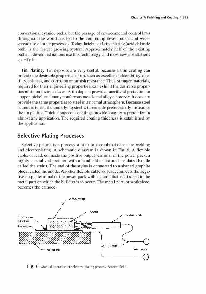
Chapter 7: Finishing and Coating / 343
conventional cyanide baths, but the passage of environmental control laws throughout the world has led to the continuing development and wide-spread use of other processes. Today, bright acid zinc plating (acid chloride bath) is the fastest growing system. Approximately half of the existing baths in developed nations use this technology, and most new installations specify it.
Tin Plating. Tin deposits are very useful, because a thin coating can provide the desirable properties of tin, such as excellent solderability, duc-tility, softness, and corrosion or tarnish resistance. thus, stronger materials, required for their engineering properties, can exhibit the desirable proper-ties of tin on their surfaces. A tin deposit provides sacrificial protection to copper, nickel, and many nonferrous metals and alloys; however, it does not provide the same properties to steel in a normal atmosphere. Because steel is anodic to tin, the underlying steel will corrode preferentially instead of the tin plating. Thick, nonporous coatings provide long-term protection in almost any application. The required coating thickness is established by the application.
Selective Plating Processes
Selective plating is a process similar to a combination of arc welding and electroplating. A schematic diagram is shown in Fig. 6. A flexible cable, or lead, connects the positive output terminal of the power pack, a highly specialized rectifier, with a handheld or fixtured insulated handle called the stylus. the end of the stylus is connected to a shaped graphite block, called the anode. Another flexible cable, or lead, connects the nega-tive output terminal of the power pack with a clamp that is attached to the metal part on which the buildup is to occur. The metal part, or workpiece, becomes the cathode.
Fig. 6 Manual operation of selective plating process. Source: ref 3
344 / Metals Fabrication—Understanding the Basics
The anode is wrapped with an absorbent material, such as cotton batting or polyester sleeving, and dipped into a liquid solution of the metal to be deposited. When this saturated anode wrap is brought into contact with the cathodic workpiece, electrical current permits the flow of metal ions from the solution in the wrap onto the surface of the workpiece, creating a buildup of metal on the workpiece surface. This technique allows the metal buildup to be limited only to the area of contact between wrapped anode and workpiece. Little or no masking of workpieces is required, and the thickness of buildups can be controlled very accurately.
Electroless Plating Processes
Electroless plating is a plating process driven entirely by chemical reac-tions—no external source of electric current is required. deposition of metal onto a part surface occurs in an aqueous solution containing ions of the desired plating metal. the process uses a reducing agent, and the workpiece surface acts as a catalyst for the reaction.
Electroless nickel plating is used to deposit nickel without the use of an electric current. The coating is deposited by an autocatalytic chemical reduction of nickel ions by hypophosphite, aminoborane, or borohydride compounds. Nickel-phosphorus (6 to 12% P), nickel-boron (~5% B), and composite electroless coatings are deposited on carbon and alloy steels, 300 and 400 series stainless steels, aluminum alloys, copper alloys, and plastics. composite coatings, which are the most recently developed types of electroless coatings, contain 20 to 30 vol% of silicon carbide, fluoro-carbons, or diamond particles dispersed in a nickel-phosphorus matrix.
Electroless nickel is an engineering coating, normally used because of excellent corrosion and wear resistance. Electroless nickel coatings are also frequently applied on aluminum to provide a solderable surface and are used on molds and dies to improve lubricity and part release. Because of these properties, electroless nickel coatings have found many applica-tions, including those in petroleum, chemicals, plastics, optics, printing, mining, aerospace, nuclear, automotive, electronics, computers, textiles, paper, and food machinery. Some advantages of electroless nickel coat-ings include:
• good resistance to corrosion and wear• excellent uniformity• Solderability and brazability• Low labor costs
Limitations include:
• higher chemical cost than electroplating• Brittleness
Chapter 7: Finishing and Coating / 345
• Poor welding characteristics due to contamination of nickel plate with nickel-phosphorus deposits
• Need to copper strike plate alloys containing significant amounts of lead, tin, cadmium, and zinc before electroless nickel can be applied
• Slower plating rate, as compared to electrolytic methods
Electroless nickel coatings are produced by the controlled chemical reduction of nickel ions onto a catalytic surface. The deposit itself is catalytic to reduction, and the reaction continues as long as the surface remains in contact with the electroless nickel solution. Because the deposit is applied without an electric current, its thickness is uniform on all areas of an article in contact with fresh solution. Electroless nickel solutions are blends of different chemicals, each performing an important function. Electroless nickel solutions contain:
• A source of nickel, usually nickel sulfate• A reducing agent to supply electrons for the reduction of nickel• energy (heat)• Complexing agents (chelators) to control the free nickel available to
the reaction• Buffering agents to resist the pH changes caused by the hydrogen gen-
erated during deposition• accelerators (exultants) to help increase the speed of the reaction• Inhibitors (stabilizers) to help control reduction• Reaction byproducts
Electroless Copper Plating. electroless copper plates much more slowly, and is a much more expensive process than electrolytic copper plating. however, electroless copper plating offers advantages over electro-lytic plating that make it the method of choice in certain cases. Electroless copper plates uniformly over all surfaces, regardless of size and shape, demonstrating 100% throwing power, and it may be plated onto noncon-ductors, or onto conductive surfaces that do not share electrical continuity. The ability to plate large racks of substrates simultaneously is also an advantage in certain instances.
components in an electroless copper plating solution include a copper source, which is a simple cupric salt such as copper sulfate, chloride, or nitrate, a reducing agent, which is usually formaldehyde, and a complexing (or chelating) component.
Plating baths are typically categorized as low build, high (heavy) build, or full build. Low build deposits approximately 0.5 mm (20 min.), or less, in about 20 min, and typically operates at ambient temperature. These deposits are typically fine-grained and exhibit good deposit integrity. They are suitable for applications such as subtractive printed wiring boards, where an electrolytic plateup process follows immediately after copper
346 / Metals Fabrication—Understanding the Basics
deposition. High (heavy) build deposits 2 to 3 mm (80 to 120 min.) in about 20 min and typically operates at elevated temperature (35 to 55 °C, or 95 to 130 °F), but room-temperature formulations are also available. Major applications are those where intervening process steps may occur prior to subsequent plateup, such as in pattern plate printed wiring boards. Full build typically deposits 25 mm (1 mil) or more of copper over a more pro-longed plating cycle of up to 15 h. By comparison, a typical electroplating process would deposit 25 mm (1 mil) of copper in 35 to 50 min. The typical temperature of operation is 55 to 80 °C (130 to 175 °F). A fundamental requirement in developing this type of bath has been the achievement and maintenance of deposit characteristics such as high ductility and tensile strength, fine grain structure, low intrinsic stress, and so on throughout the thick deposit. This type of bath has been employed primarily for additive-type printed wiring board applications. This deposit typically represents the full metal thickness required for the applications and hence eliminates the need for electroplating altogether.
By far the most important commercial application of electroless copper plating has been the plated-through-hole process for fabricating printed wiring boards. Other important application areas include decorative plating of plastics, electromagnetic interference shielding of electronic components, and coating of injection molded plastic circuit boards, or molded interconnect devices.
Hot Dip Coating of Steels
hot dip coating processes are used to apply coatings of zinc, zinc-iron, aluminum, aluminum-silicon alloy, Zn-5Al alloy, 55Al-Zn alloy, and lead-tin alloy to carbon steels. Metals such as chromium and titanium cannot be applied to steel by hot dipping because of their high melting points. Tin, which prior to 1937 was applied only by hot dipping, is now almost always electrodeposited, because it is very difficult to produce the thin and uniform coatings required for tinplate by means of hot dipping.
The hot dip process consists of immersing the steel in a molten bath of the coating metal. Zinc coating (galvanizing) protects steel galvanically because the zinc is anodic to the steel base metal and therefore corrodes preferentially in most environments. hot dip galvanizing affords adequate atmospheric corrosion protection to steel. the protective coating usually consists of several layers (Table 3 and Fig. 7). Those closest to the base metal are composed of iron-zinc compounds; these, in turn, can be covered by an outer layer consisting almost entirely of zinc. The complex structure of layers that comprise a galvanized coating varies greatly in chemical composition and physical and mechanical properties, being affected by chemical activity, diffusion, and subsequent cooling. Small differences in coating composition, bath temperature, time of immersion, and rate of
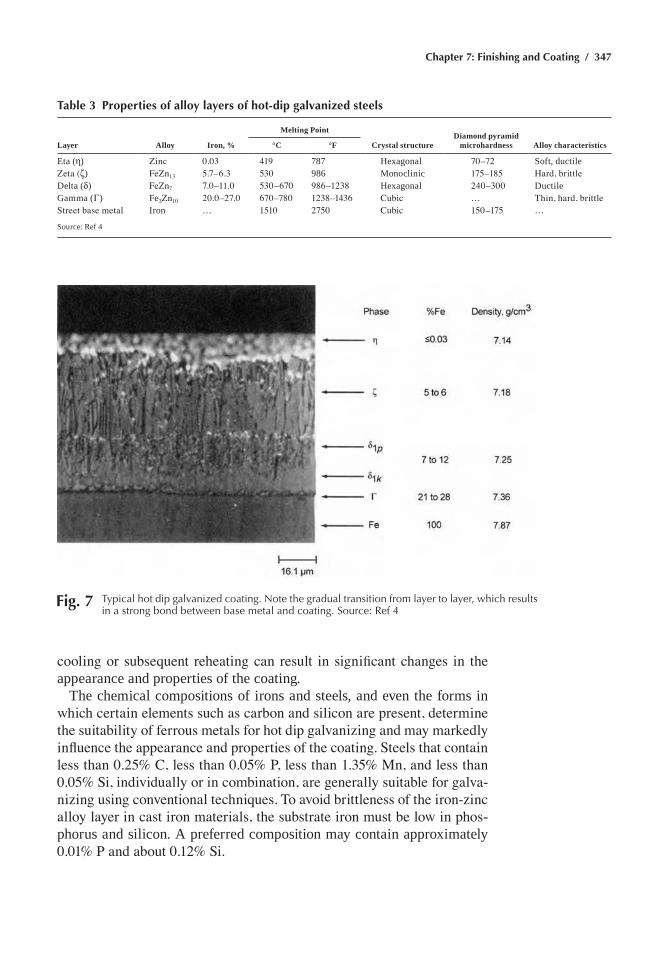
Chapter 7: Finishing and Coating / 347
cooling or subsequent reheating can result in significant changes in the appearance and properties of the coating.
the chemical compositions of irons and steels, and even the forms in which certain elements such as carbon and silicon are present, determine the suitability of ferrous metals for hot dip galvanizing and may markedly influence the appearance and properties of the coating. Steels that contain less than 0.25% C, less than 0.05% P, less than 1.35% Mn, and less than 0.05% Si, individually or in combination, are generally suitable for galva-nizing using conventional techniques. To avoid brittleness of the iron-zinc alloy layer in cast iron materials, the substrate iron must be low in phos-phorus and silicon. a preferred composition may contain approximately 0.01% P and about 0.12% Si.
Table 3 Properties of alloy layers of hot-dip galvanized steels
Layer Alloy Iron, %
Melting Point
Crystal structureDiamond pyramid
microhardness Alloy characteristics°C °F
eta (η) Zinc 0.03 419 787 hexagonal 70–72 Soft, ductileZeta (ζ) FeZn13 5.7–6.3 530 986 Monoclinic 175–185 Hard, brittledelta (δ) FeZn7 7.0–11.0 530–670 986–1238 hexagonal 240–300 ductilegamma (Γ) fe3Zn10 20.0–27.0 670–780 1238–1436 Cubic … Thin, hard, brittleStreet base metal iron … 1510 2750 Cubic 150–175 …
Source: ref 4
Fig. 7 typical hot dip galvanized coating. Note the gradual transition from layer to layer, which results in a strong bond between base metal and coating. Source: ref 4
348 / Metals Fabrication—Understanding the Basics
The molten zinc bath is usually operated at temperatures in the range from 445 to 465 °C (830 to 870 °F). At 480 °C (900 °F) and above, the dis-solution rate of iron and steel in zinc is extremely rapid, and the effects of these temperatures on both workpiece and galvanizing tank are generally harmful. The thickness of the coating is primarily controlled by immersion time, withdrawal rate, and the composition of the iron or steel substrate material. Immersion time usually is from 1 to 5 min, and withdrawal rate for most articles is approximately 1.5 m/min (5 ft/min). Processing of hot dip galvanized coatings involves either batch or continuous processing. the continuous process is more advantageous for sheet steels, whereas the batch process is normally used for individual parts.
other types of hot dip coatings include zinc-iron, aluminum, zinc-alu-minum, aluminum-zinc, and lead-tin. aluminum hot dip coatings provide carbon steels with resistance to both corrosion and heat. In many environ-ments, aluminum protects steel galvanically in much the same way as zinc. Zinc-aluminum and aluminum-zinc alloys are also applied to steel by hot dipping. heating aluminized steel results in the formation of an iron-alu-minum intermetallic compound that resists oxidation at temperatures up to approximately 800 °C (1500 °F). Aluminized steel is often used where heat resistance is required—for example, in automotive exhaust systems. Hot dip lead coatings are sometimes used on steel that will be exposed to sulfuric acid fumes or other aggressive chemical environments. terne plate, a lead-tin alloy coating, gives more protection than pure lead coat-ings and is solderable.
Babbitting
Babbitting is a process in which relatively soft metals are bonded to a stronger shell or stiffener, which supports the weight and torsion of a rotat-ing, oscillating, or sliding shaft. The babbitt, being softer than the shaft and having excellent antifrictional qualities, prevents galling and/or scoring of the shaft over long periods of use. Babbitt metals, which are more widely known as white metals, are comprised principally of tin alloys (hardened with copper and antimony) or lead alloys (hardened with tin and antimony and, in some cases, arsenic). In the babbitting process, the relatively soft bearing material (babbitt) is bonded to a stronger supporting base metal, typically mild steel, cast iron, or bronze. The base metal may be in the form of mild steel strip unwound from a coil, a half-round mild steel press-ing or bushing, or a bronze or iron casting. The bonded bimetal material is shaped and machined to make plain, fluid film lubricated bearings for a wide variety of automotive, industrial, and marine applications.
Babbitt is used in small bearings for high-volume applications, such as electric motors and internal combustion engines, and for large rotating and reciprocating machinery with low to modest volume requirements, such as high-speed turbines and low-speed marine diesel engines. In addition,
Chapter 7: Finishing and Coating / 349
babbitt has been used for jewelry, shot, filler metals, and various other applications. Lead-base alloys enjoy a cost advantage, while tin alloys offer modest technical advantages, particularly in high-speed centrifugal equip-ment. It should be noted that government regulations now discourage the use of lead-base alloys for health and hazardous waste disposal reasons. Babbitting of bearing shells can be accomplished by three methods: static babbitting (hand casting), centrifugal casting, and metal spray babbitting.
Centrifugal casting and static (gravity) casting are the two babbitting methods used in the manufacture and repair of large, low-volume journal (radial) and thrust bearings. Centrifugal casting of journal bearings offers both technical and economic advantages if special spinning equipment is available. Flat shapes (thrust bearings) are usually statically cast. Repair-ing of industrial and marine babbitted bearings is routinely accomplished by melting off the old metal and rebabbitting the shells with new metal using the same basic casting methods for producing new products. Emer-gency repair methods using proprietary tinning compounds, babbitt spray, or welding techniques can be employed.
Weld-Overlay Coatings
Welding is a solidification method for applying coatings with corrosion, wear, and erosion resistance. Weld-overlay coatings, sometimes referred to as hardfacing, offer unique advantages over other coating systems in that the overlay/substrate weld provides a metallurgical bond that is not sus-ceptible to spallation and can be applied free of porosity or other defects. Welded deposits of surface alloys can be applied in thicknesses greater than most other techniques, typically in the range of 3 to 10 mm (0.12 to 0.40 in.). Weld overlays are very versatile because a large number of commercially available alloys can be selected to provide protection from a wide range of environmental degradation mechanisms.
during weld-overlay surfacing, the coating material is raised to its melt-ing point and then solidified on the surface of the substrate, which means that metals and alloys used for this purpose must have melting points similar to or less than the substrate material. The effectiveness of the weld-overlay coating depends mainly on the welding process and the overlay alloy composition. the welding process must apply the protective overlays at high deposition rates and thermal efficiency, with good control over the overlay/substrate dilution and coating thickness. The overlay alloy compo-sition must be selected to provide the required properties to prevent coating degradation, and the alloy composition must be readily weldable.
A number of welding processes are available for applying protective weld overlays, and many welding parameters must be considered when attempting to optimize a particular process for a given application. the process principles and their characteristics for some processes are sum-marized for comparison purposes in Table 4. In addition to the torch and
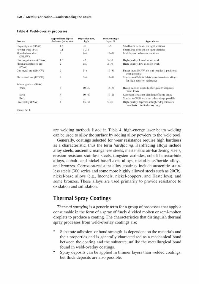
350 / Metals Fabrication—Understanding the Basics
arc welding methods listed in Table 4, high-energy laser beam welding can be used to alloy the surface by adding alloy powders to the weld pool.
generally, coatings selected for wear resistance require high hardness as a characteristic, thus the term hardfacing. hardfacing alloys include alloy steels, austenitic manganese steels, martensitic air-hardening steels, erosion-resistant stainless steels, tungsten carbides, cobalt-base/carbide alloys, cobalt- and nickel-base/Laves alloys, nickel-base/boride alloys, and bronzes. Corrosion-resistant alloy coatings include austenitic stain-less steels (300 series and some more highly alloyed steels such as 20Cb), nickel-base alloys (e.g., Inconels, nickel-coppers, and Hastelloys), and some bronzes. These alloys are used primarily to provide resistance to oxidation and sulfidation.
Thermal Spray Coatings
Thermal spraying is a generic term for a group of processes that apply a consumable in the form of a spray of finely divided molten or semi-molten droplets to produce a coating. the characteristics that distinguish thermal spray processes from weld-overlay coatings are:
• Substrate adhesion, or bond strength, is dependent on the materials and their properties and is generally characterized as a mechanical bond between the coating and the substrate, unlike the metallurgical bond found in weld-overlay coatings.
• Spray deposits can be applied in thinner layers than welded coatings, but thick deposits are also possible.
Table 4 Weld-overlay processes
ProcessApproximate deposit thickness (min), mm
Deposition rate, kg/h
Dilution single layer, % Typical uses
Oxyacetylene (OAW) 1.5 ≤1 1–5 Small area deposits on light sectionsPowder weld (PW) 0.1 0.2–1 Small area deposits on light sectionsShielded metal arc
(SMAW)3 1–4 15–30 Multilayers on heavier sections
Gas tungsten arc (GTAW) 1.5 ≤2 5–10 High-quality, low-dilution workPlasma transferred arc
(PAW)2 ≤10 2–10 High-quality, low-dilution work
Gas metal arc (GMAW) 2 3–6 10–30 Faster than SMAW, no stub-end loss; positional work possible
Flux-cored arc (FCAW) 2 3–6 15–30 Similar to GMAW. Mainly for iron-base alloys for high abrasion resistance
Submerged arc (SAW) Wire 3 10–30 15–30 Heavy section work; higher-quality deposits
than FCAW Strip 4 10–40 10–25 corrosion-resistant cladding of large areas Bulk … … … Similar to SAW wire but other alloys possibleElectroslag (ESW) 4 15–35 5–20 high-quality deposits at higher deposit rates
than SAW. Limited alloy range
Source: ref 4
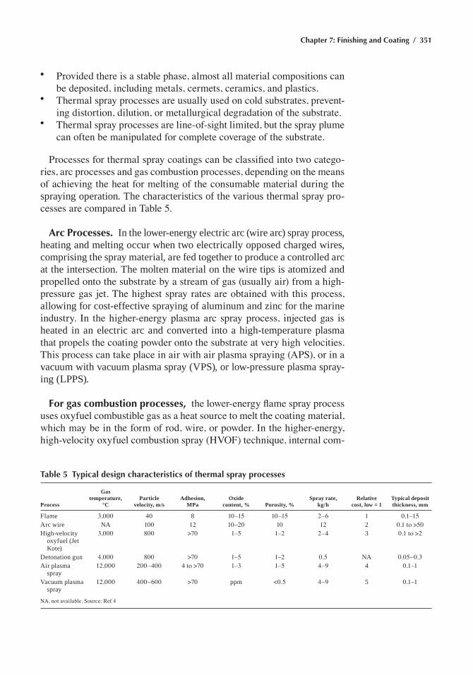
Chapter 7: Finishing and Coating / 351
• Provided there is a stable phase, almost all material compositions can be deposited, including metals, cermets, ceramics, and plastics.
• Thermal spray processes are usually used on cold substrates, prevent-ing distortion, dilution, or metallurgical degradation of the substrate.
• Thermal spray processes are line-of-sight limited, but the spray plume can often be manipulated for complete coverage of the substrate.
Processes for thermal spray coatings can be classified into two catego-ries, arc processes and gas combustion processes, depending on the means of achieving the heat for melting of the consumable material during the spraying operation. the characteristics of the various thermal spray pro-cesses are compared in Table 5.
Arc Processes. in the lower-energy electric arc (wire arc) spray process, heating and melting occur when two electrically opposed charged wires, comprising the spray material, are fed together to produce a controlled arc at the intersection. the molten material on the wire tips is atomized and propelled onto the substrate by a stream of gas (usually air) from a high-pressure gas jet. The highest spray rates are obtained with this process, allowing for cost-effective spraying of aluminum and zinc for the marine industry. In the higher-energy plasma arc spray process, injected gas is heated in an electric arc and converted into a high-temperature plasma that propels the coating powder onto the substrate at very high velocities. This process can take place in air with air plasma spraying (APS), or in a vacuum with vacuum plasma spray (VPS), or low-pressure plasma spray-ing (LPPS).
For gas combustion processes, the lower-energy flame spray process uses oxyfuel combustible gas as a heat source to melt the coating material, which may be in the form of rod, wire, or powder. In the higher-energy, high-velocity oxyfuel combustion spray (HVOF) technique, internal com-
Table 5 Typical design characteristics of thermal spray processes
Process
Gas temperature,
°CParticle
velocity, m/sAdhesion,
MPaOxide
content, % Porosity, %Spray rate,
kg/hRelative
cost, low = 1Typical deposit thickness, mm
flame 3,000 40 8 10–15 10–15 2–6 1 0.1–15arc wire na 100 12 10–20 10 12 2 0.1 to >50high-velocity
oxyfuel (Jet Kote)
3,000 800 >70 1–5 1–2 2–4 3 0.1 to >2
detonation gun 4,000 800 >70 1–5 1–2 0.5 na 0.05–0.3air plasma
spray12,000 200–400 4 to >70 1–3 1–5 4–9 4 0.1–1
Vacuum plasma spray
12,000 400–600 >70 ppm <0.5 4–9 5 0.1–1
NA, not available. Source: Ref 4
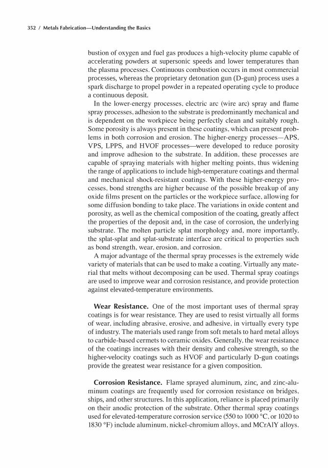
352 / Metals Fabrication—Understanding the Basics
bustion of oxygen and fuel gas produces a high-velocity plume capable of accelerating powders at supersonic speeds and lower temperatures than the plasma processes. Continuous combustion occurs in most commercial processes, whereas the proprietary detonation gun (d-gun) process uses a spark discharge to propel powder in a repeated operating cycle to produce a continuous deposit.
In the lower-energy processes, electric arc (wire arc) spray and flame spray processes, adhesion to the substrate is predominantly mechanical and is dependent on the workpiece being perfectly clean and suitably rough. Some porosity is always present in these coatings, which can present prob-lems in both corrosion and erosion. The higher-energy processes—APS, VPS, LPPS, and hVof processes—were developed to reduce porosity and improve adhesion to the substrate. In addition, these processes are capable of spraying materials with higher melting points, thus widening the range of applications to include high-temperature coatings and thermal and mechanical shock-resistant coatings. With these higher-energy pro-cesses, bond strengths are higher because of the possible breakup of any oxide films present on the particles or the workpiece surface, allowing for some diffusion bonding to take place. The variations in oxide content and porosity, as well as the chemical composition of the coating, greatly affect the properties of the deposit and, in the case of corrosion, the underlying substrate. The molten particle splat morphology and, more importantly, the splat-splat and splat-substrate interface are critical to properties such as bond strength, wear, erosion, and corrosion.
A major advantage of the thermal spray processes is the extremely wide variety of materials that can be used to make a coating. Virtually any mate-rial that melts without decomposing can be used. Thermal spray coatings are used to improve wear and corrosion resistance, and provide protection against elevated-temperature environments.
Wear Resistance. one of the most important uses of thermal spray coatings is for wear resistance. they are used to resist virtually all forms of wear, including abrasive, erosive, and adhesive, in virtually every type of industry. the materials used range from soft metals to hard metal alloys to carbide-based cermets to ceramic oxides. Generally, the wear resistance of the coatings increases with their density and cohesive strength, so the higher-velocity coatings such as hVof and particularly d-gun coatings provide the greatest wear resistance for a given composition.
Corrosion Resistance. flame sprayed aluminum, zinc, and zinc-alu-minum coatings are frequently used for corrosion resistance on bridges, ships, and other structures. in this application, reliance is placed primarily on their anodic protection of the substrate. Other thermal spray coatings used for elevated-temperature corrosion service (550 to 1000 °C, or 1020 to 1830 °F) include aluminum, nickel-chromium alloys, and MCrAlY alloys.
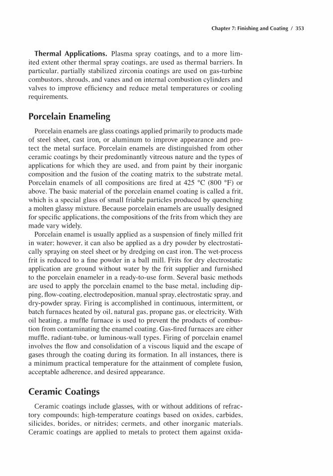
Chapter 7: Finishing and Coating / 353
Thermal Applications. Plasma spray coatings, and to a more lim-ited extent other thermal spray coatings, are used as thermal barriers. In particular, partially stabilized zirconia coatings are used on gas-turbine combustors, shrouds, and vanes and on internal combustion cylinders and valves to improve efficiency and reduce metal temperatures or cooling requirements.
Porcelain Enameling
Porcelain enamels are glass coatings applied primarily to products made of steel sheet, cast iron, or aluminum to improve appearance and pro-tect the metal surface. Porcelain enamels are distinguished from other ceramic coatings by their predominantly vitreous nature and the types of applications for which they are used, and from paint by their inorganic composition and the fusion of the coating matrix to the substrate metal. Porcelain enamels of all compositions are fired at 425 °C (800 °F) or above. The basic material of the porcelain enamel coating is called a frit, which is a special glass of small friable particles produced by quenching a molten glassy mixture. Because porcelain enamels are usually designed for specific applications, the compositions of the frits from which they are made vary widely.
Porcelain enamel is usually applied as a suspension of finely milled frit in water; however, it can also be applied as a dry powder by electrostati-cally spraying on steel sheet or by dredging on cast iron. The wet-process frit is reduced to a fine powder in a ball mill. Frits for dry electrostatic application are ground without water by the frit supplier and furnished to the porcelain enameler in a ready-to-use form. Several basic methods are used to apply the porcelain enamel to the base metal, including dip-ping, flow-coating, electrodeposition, manual spray, electrostatic spray, and dry-powder spray. firing is accomplished in continuous, intermittent, or batch furnaces heated by oil, natural gas, propane gas, or electricity. With oil heating, a muffle furnace is used to prevent the products of combus-tion from contaminating the enamel coating. Gas-fired furnaces are either muffle, radiant-tube, or luminous-wall types. Firing of porcelain enamel involves the flow and consolidation of a viscous liquid and the escape of gases through the coating during its formation. in all instances, there is a minimum practical temperature for the attainment of complete fusion, acceptable adherence, and desired appearance.
Ceramic Coatings
ceramic coatings include glasses, with or without additions of refrac-tory compounds; high-temperature coatings based on oxides, carbides, silicides, borides, or nitrides; cermets, and other inorganic materials. ceramic coatings are applied to metals to protect them against oxida-
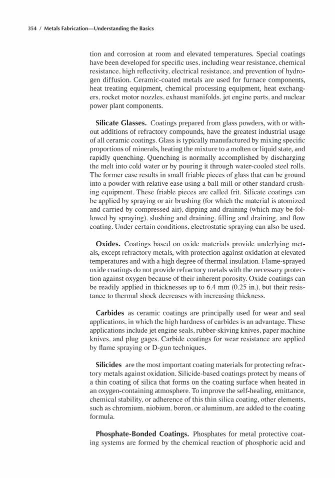
354 / Metals Fabrication—Understanding the Basics
tion and corrosion at room and elevated temperatures. Special coatings have been developed for specific uses, including wear resistance, chemical resistance, high reflectivity, electrical resistance, and prevention of hydro-gen diffusion. ceramic-coated metals are used for furnace components, heat treating equipment, chemical processing equipment, heat exchang-ers, rocket motor nozzles, exhaust manifolds, jet engine parts, and nuclear power plant components.
Silicate Glasses. coatings prepared from glass powders, with or with-out additions of refractory compounds, have the greatest industrial usage of all ceramic coatings. Glass is typically manufactured by mixing specific proportions of minerals, heating the mixture to a molten or liquid state, and rapidly quenching. Quenching is normally accomplished by discharging the melt into cold water or by pouring it through water-cooled steel rolls. The former case results in small friable pieces of glass that can be ground into a powder with relative ease using a ball mill or other standard crush-ing equipment. These friable pieces are called frit. Silicate coatings can be applied by spraying or air brushing (for which the material is atomized and carried by compressed air), dipping and draining (which may be fol-lowed by spraying), slushing and draining, filling and draining, and flow coating. Under certain conditions, electrostatic spraying can also be used.
Oxides. Coatings based on oxide materials provide underlying met-als, except refractory metals, with protection against oxidation at elevated temperatures and with a high degree of thermal insulation. flame-sprayed oxide coatings do not provide refractory metals with the necessary protec-tion against oxygen because of their inherent porosity. Oxide coatings can be readily applied in thicknesses up to 6.4 mm (0.25 in.), but their resis-tance to thermal shock decreases with increasing thickness.
Carbides as ceramic coatings are principally used for wear and seal applications, in which the high hardness of carbides is an advantage. These applications include jet engine seals, rubber-skiving knives, paper machine knives, and plug gages. Carbide coatings for wear resistance are applied by flame spraying or D-gun techniques.
Silicides are the most important coating materials for protecting refrac-tory metals against oxidation. Silicide-based coatings protect by means of a thin coating of silica that forms on the coating surface when heated in an oxygen-containing atmosphere. to improve the self-healing, emittance, chemical stability, or adherence of this thin silica coating, other elements, such as chromium, niobium, boron, or aluminum, are added to the coating formula.
Phosphate-Bonded Coatings. Phosphates for metal protective coat-ing systems are formed by the chemical reaction of phosphoric acid and
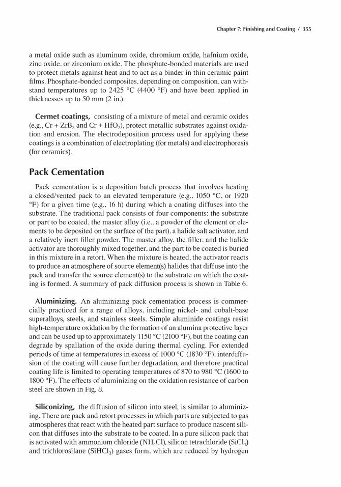
Chapter 7: Finishing and Coating / 355
a metal oxide such as aluminum oxide, chromium oxide, hafnium oxide, zinc oxide, or zirconium oxide. The phosphate-bonded materials are used to protect metals against heat and to act as a binder in thin ceramic paint films. Phosphate-bonded composites, depending on composition, can with-stand temperatures up to 2425 °C (4400 °F) and have been applied in thicknesses up to 50 mm (2 in.).
Cermet coatings, consisting of a mixture of metal and ceramic oxides (e.g., Cr + ZrB2 and cr + hfo2), protect metallic substrates against oxida-tion and erosion. the electrodeposition process used for applying these coatings is a combination of electroplating (for metals) and electrophoresis (for ceramics).
Pack Cementation
Pack cementation is a deposition batch process that involves heating a closed/vented pack to an elevated temperature (e.g., 1050 °C, or 1920 °F) for a given time (e.g., 16 h) during which a coating diffuses into the substrate. The traditional pack consists of four components: the substrate or part to be coated, the master alloy (i.e., a powder of the element or ele-ments to be deposited on the surface of the part), a halide salt activator, and a relatively inert filler powder. The master alloy, the filler, and the halide activator are thoroughly mixed together, and the part to be coated is buried in this mixture in a retort. When the mixture is heated, the activator reacts to produce an atmosphere of source element(s) halides that diffuse into the pack and transfer the source element(s) to the substrate on which the coat-ing is formed. A summary of pack diffusion process is shown in Table 6.
Aluminizing. An aluminizing pack cementation process is commer-cially practiced for a range of alloys, including nickel- and cobalt-base superalloys, steels, and stainless steels. Simple aluminide coatings resist high-temperature oxidation by the formation of an alumina protective layer and can be used up to approximately 1150 °C (2100 °F), but the coating can degrade by spallation of the oxide during thermal cycling. For extended periods of time at temperatures in excess of 1000 °C (1830 °F), interdiffu-sion of the coating will cause further degradation, and therefore practical coating life is limited to operating temperatures of 870 to 980 °C (1600 to 1800 °F). The effects of aluminizing on the oxidation resistance of carbon steel are shown in fig. 8.
Siliconizing, the diffusion of silicon into steel, is similar to aluminiz-ing. There are pack and retort processes in which parts are subjected to gas atmospheres that react with the heated part surface to produce nascent sili-con that diffuses into the substrate to be coated. In a pure silicon pack that is activated with ammonium chloride (nh4cl), silicon tetrachloride (Sicl4) and trichlorosilane (Sihcl3) gases form, which are reduced by hydrogen
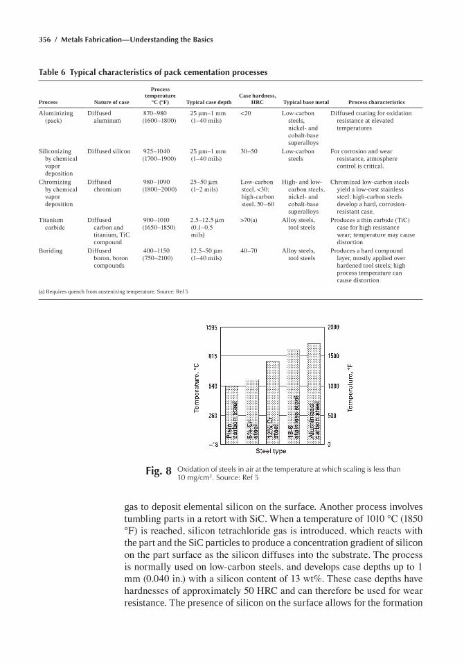
356 / Metals Fabrication—Understanding the Basics
gas to deposit elemental silicon on the surface. another process involves tumbling parts in a retort with SiC. When a temperature of 1010 °C (1850 °F) is reached, silicon tetrachloride gas is introduced, which reacts with the part and the Sic particles to produce a concentration gradient of silicon on the part surface as the silicon diffuses into the substrate. The process is normally used on low-carbon steels, and develops case depths up to 1 mm (0.040 in.) with a silicon content of 13 wt%. These case depths have hardnesses of approximately 50 HRC and can therefore be used for wear resistance. the presence of silicon on the surface allows for the formation
Table 6 Typical characteristics of pack cementation processes
Process Nature of case
Process temperature
°C (°F) Typical case depthCase hardness,
HRC Typical base metal Process characteristics
aluminizing (pack)
diffused aluminum
870–980 (1600–1800)
25 mm–1 mm (1–40 mils)
<20 Low-carbon steels, nickel- and cobalt-base superalloys
diffused coating for oxidation resistance at elevated temperatures
Siliconizing by chemical vapor deposition
diffused silicon 925–1040 (1700–1900)
25 mm–1 mm (1–40 mils)
30–50 Low-carbon steels
for corrosion and wear resistance, atmosphere control is critical.
chromizing by chemical vapor deposition
diffused chromium
980–1090 (1800–2000)
25–50 mm (1–2 mils)
Low-carbon steel, <30; high-carbon steel, 50–60
high- and low-carbon steels, nickel- and cobalt-base superalloys
Chromized low-carbon steels yield a low-cost stainless steel; high-carbon steels develop a hard, corrosion-resistant case.
titanium carbide
diffused carbon and titanium, tic compound
900–1010 (1650–1850)
2.5–12.5 mm (0.1–0.5 mils)
>70(a) alloy steels, tool steels
Produces a thin carbide (TiC) case for high resistance wear; temperature may cause distortion
Boriding diffused boron, boron compounds
400–1150 (750–2100)
12.5–50 mm (1–40 mils)
40–70 alloy steels, tool steels
Produces a hard compound layer, mostly applied over hardened tool steels; high process temperature can cause distortion
(a) requires quench from austenizing temperature. Source: ref 5
Fig. 8 Oxidation of steels in air at the temperature at which scaling is less than 10 mg/cm2. Source: ref 5
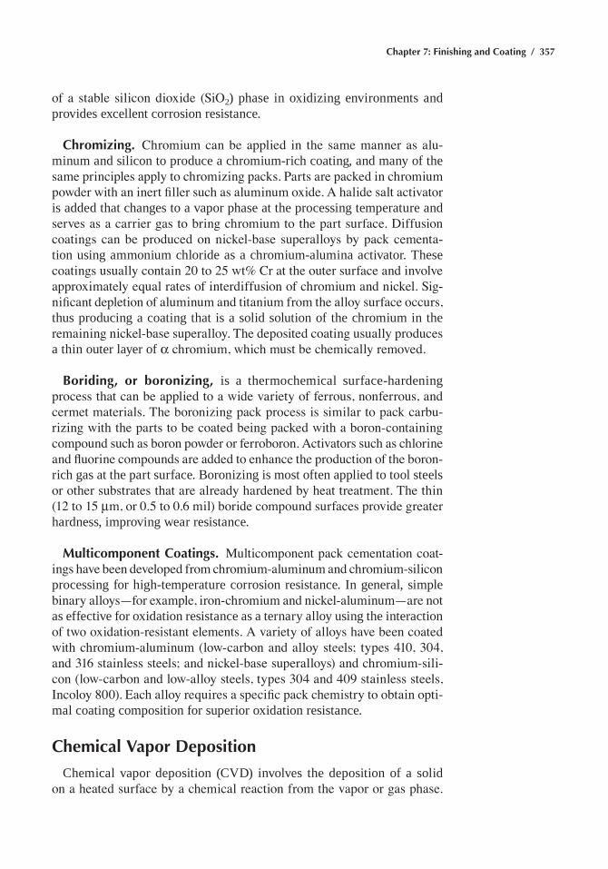
Chapter 7: Finishing and Coating / 357
of a stable silicon dioxide (SiO2) phase in oxidizing environments and provides excellent corrosion resistance.
Chromizing. Chromium can be applied in the same manner as alu-minum and silicon to produce a chromium-rich coating, and many of the same principles apply to chromizing packs. Parts are packed in chromium powder with an inert filler such as aluminum oxide. A halide salt activator is added that changes to a vapor phase at the processing temperature and serves as a carrier gas to bring chromium to the part surface. Diffusion coatings can be produced on nickel-base superalloys by pack cementa-tion using ammonium chloride as a chromium-alumina activator. these coatings usually contain 20 to 25 wt% Cr at the outer surface and involve approximately equal rates of interdiffusion of chromium and nickel. Sig-nificant depletion of aluminum and titanium from the alloy surface occurs, thus producing a coating that is a solid solution of the chromium in the remaining nickel-base superalloy. The deposited coating usually produces a thin outer layer of α chromium, which must be chemically removed.
Boriding, or boronizing, is a thermochemical surface-hardening process that can be applied to a wide variety of ferrous, nonferrous, and cermet materials. The boronizing pack process is similar to pack carbu-rizing with the parts to be coated being packed with a boron-containing compound such as boron powder or ferroboron. Activators such as chlorine and fluorine compounds are added to enhance the production of the boron-rich gas at the part surface. Boronizing is most often applied to tool steels or other substrates that are already hardened by heat treatment. The thin (12 to 15 mm, or 0.5 to 0.6 mil) boride compound surfaces provide greater hardness, improving wear resistance.
Multicomponent Coatings. Multicomponent pack cementation coat-ings have been developed from chromium-aluminum and chromium-silicon processing for high-temperature corrosion resistance. in general, simple binary alloys—for example, iron-chromium and nickel-aluminum—are not as effective for oxidation resistance as a ternary alloy using the interaction of two oxidation-resistant elements. A variety of alloys have been coated with chromium-aluminum (low-carbon and alloy steels; types 410, 304, and 316 stainless steels; and nickel-base superalloys) and chromium-sili-con (low-carbon and low-alloy steels, types 304 and 409 stainless steels, Incoloy 800). Each alloy requires a specific pack chemistry to obtain opti-mal coating composition for superior oxidation resistance.
Chemical Vapor Deposition
chemical vapor deposition (cVd) involves the deposition of a solid on a heated surface by a chemical reaction from the vapor or gas phase.
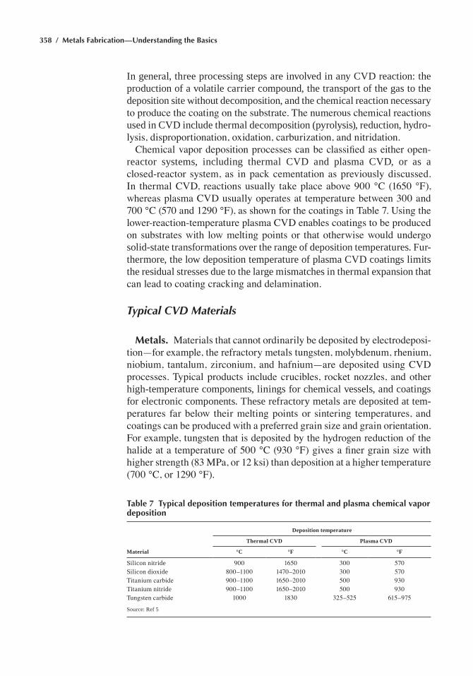
358 / Metals Fabrication—Understanding the Basics
in general, three processing steps are involved in any cVd reaction: the production of a volatile carrier compound, the transport of the gas to the deposition site without decomposition, and the chemical reaction necessary to produce the coating on the substrate. The numerous chemical reactions used in cVd include thermal decomposition (pyrolysis), reduction, hydro-lysis, disproportionation, oxidation, carburization, and nitridation.
Chemical vapor deposition processes can be classified as either open-reactor systems, including thermal cVd and plasma cVd, or as a closed-reactor system, as in pack cementation as previously discussed. In thermal CVD, reactions usually take place above 900 °C (1650 °F), whereas plasma CVD usually operates at temperature between 300 and 700 °C (570 and 1290 °F), as shown for the coatings in Table 7. Using the lower-reaction-temperature plasma CVD enables coatings to be produced on substrates with low melting points or that otherwise would undergo solid-state transformations over the range of deposition temperatures. fur-thermore, the low deposition temperature of plasma cVd coatings limits the residual stresses due to the large mismatches in thermal expansion that can lead to coating cracking and delamination.
Typical CVD Materials
Metals. Materials that cannot ordinarily be deposited by electrodeposi-tion—for example, the refractory metals tungsten, molybdenum, rhenium, niobium, tantalum, zirconium, and hafnium—are deposited using CVD processes. Typical products include crucibles, rocket nozzles, and other high-temperature components, linings for chemical vessels, and coatings for electronic components. these refractory metals are deposited at tem-peratures far below their melting points or sintering temperatures, and coatings can be produced with a preferred grain size and grain orientation. For example, tungsten that is deposited by the hydrogen reduction of the halide at a temperature of 500 °C (930 °F) gives a finer grain size with higher strength (83 MPa, or 12 ksi) than deposition at a higher temperature (700 °C, or 1290 °F).
Table 7 Typical deposition temperatures for thermal and plasma chemical vapor deposition
Material
Deposition temperature
Thermal CVD Plasma CVD
°C °F °C °F
Silicon nitride 900 1650 300 570Silicon dioxide 800–1100 1470–2010 300 570Titanium carbide 900–1100 1650–2010 500 930titanium nitride 900–1100 1650–2010 500 930Tungsten carbide 1000 1830 325–525 615–975
Source: ref 5
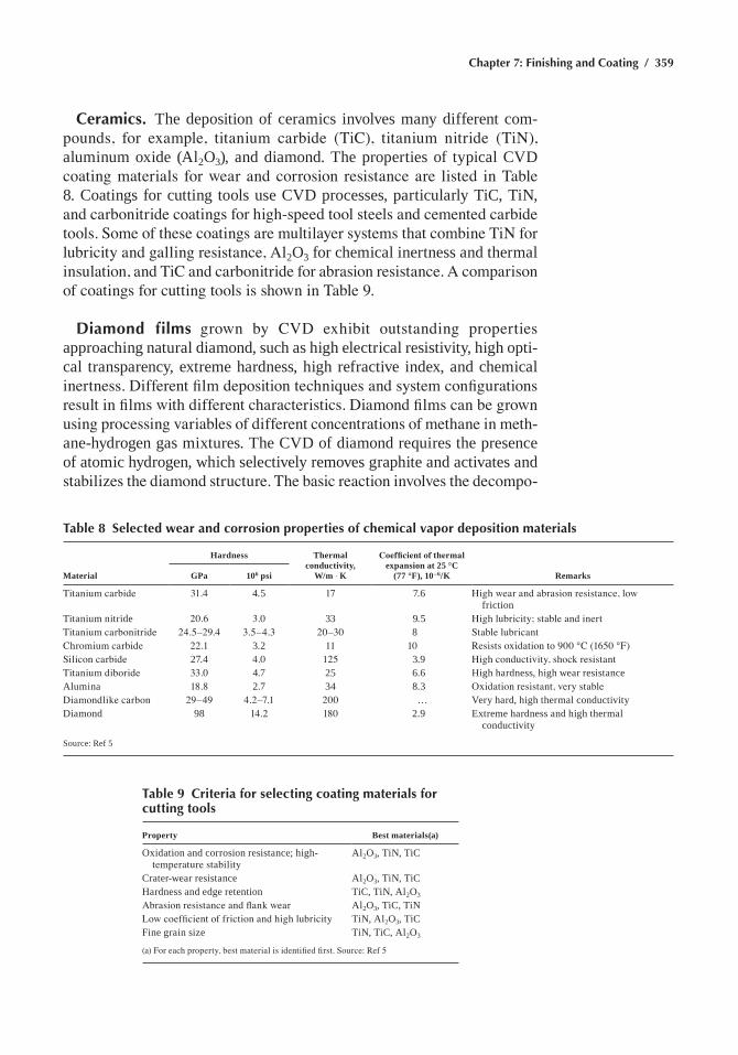
Chapter 7: Finishing and Coating / 359
Ceramics. the deposition of ceramics involves many different com-pounds, for example, titanium carbide (TiC), titanium nitride (TiN), aluminum oxide (al2o3), and diamond. the properties of typical cVd coating materials for wear and corrosion resistance are listed in Table 8. coatings for cutting tools use cVd processes, particularly tic, tin, and carbonitride coatings for high-speed tool steels and cemented carbide tools. Some of these coatings are multilayer systems that combine TiN for lubricity and galling resistance, Al2o3 for chemical inertness and thermal insulation, and TiC and carbonitride for abrasion resistance. A comparison of coatings for cutting tools is shown in Table 9.
Diamond films grown by CVD exhibit outstanding properties approaching natural diamond, such as high electrical resistivity, high opti-cal transparency, extreme hardness, high refractive index, and chemical inertness. Different film deposition techniques and system configurations result in films with different characteristics. Diamond films can be grown using processing variables of different concentrations of methane in meth-ane-hydrogen gas mixtures. the cVd of diamond requires the presence of atomic hydrogen, which selectively removes graphite and activates and stabilizes the diamond structure. The basic reaction involves the decompo-
Table 8 Selected wear and corrosion properties of chemical vapor deposition materials
Material
Hardness Thermal conductivity,
W/m ◊ K
Coefficient of thermal expansion at 25 °C
(77 °F), 10–6/K RemarksGPa 106 psi
Titanium carbide 31.4 4.5 17 7.6 High wear and abrasion resistance, low friction
titanium nitride 20.6 3.0 33 9.5 High lubricity; stable and inertTitanium carbonitride 24.5–29.4 3.5–4.3 20–30 8 Stable lubricantChromium carbide 22.1 3.2 11 10 Resists oxidation to 900 °C (1650 °F)Silicon carbide 27.4 4.0 125 3.9 High conductivity, shock resistantTitanium diboride 33.0 4.7 25 6.6 high hardness, high wear resistancealumina 18.8 2.7 34 8.3 Oxidation resistant, very stableDiamondlike carbon 29–49 4.2–7.1 200 … Very hard, high thermal conductivitydiamond 98 14.2 180 2.9 extreme hardness and high thermal
conductivity
Source: ref 5
Table 9 Criteria for selecting coating materials for cutting tools
Property Best materials(a)
oxidation and corrosion resistance; high-temperature stability
al2o3, tin, tic
crater-wear resistance al2o3, tin, tichardness and edge retention tic, tin, al2o3
Abrasion resistance and flank wear al2o3, tic, tinLow coefficient of friction and high lubricity tin, al2o3, ticfine grain size tin, tic, al2o3
(a) For each property, best material is identified first. Source: Ref 5
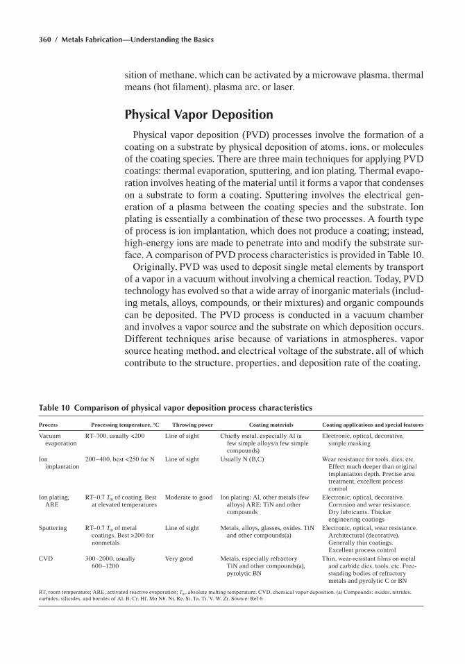
360 / Metals Fabrication—Understanding the Basics
sition of methane, which can be activated by a microwave plasma, thermal means (hot filament), plasma arc, or laser.
Physical Vapor Deposition
Physical vapor deposition (PVd) processes involve the formation of a coating on a substrate by physical deposition of atoms, ions, or molecules of the coating species. there are three main techniques for applying PVd coatings: thermal evaporation, sputtering, and ion plating. thermal evapo-ration involves heating of the material until it forms a vapor that condenses on a substrate to form a coating. Sputtering involves the electrical gen-eration of a plasma between the coating species and the substrate. Ion plating is essentially a combination of these two processes. A fourth type of process is ion implantation, which does not produce a coating; instead, high-energy ions are made to penetrate into and modify the substrate sur-face. A comparison of PVD process characteristics is provided in Table 10.
Originally, PVD was used to deposit single metal elements by transport of a vapor in a vacuum without involving a chemical reaction. today, PVd technology has evolved so that a wide array of inorganic materials (includ-ing metals, alloys, compounds, or their mixtures) and organic compounds can be deposited. The PVD process is conducted in a vacuum chamber and involves a vapor source and the substrate on which deposition occurs. Different techniques arise because of variations in atmospheres, vapor source heating method, and electrical voltage of the substrate, all of which contribute to the structure, properties, and deposition rate of the coating.
Table 10 Comparison of physical vapor deposition process characteristics
Process Processing temperature, °C Throwing power Coating materials Coating applications and special features
Vacuum evaporation
RT–700, usually <200 Line of sight Chiefly metal, especially Al (a few simple alloys/a few simple compounds)
electronic, optical, decorative, simple masking
ion implantation
200–400, best <250 for N Line of sight usually n (B,c) Wear resistance for tools, dies, etc. effect much deeper than original implantation depth. Precise area treatment, excellent process control
ion plating, are
RT–0.7 Tm of coating. Best at elevated temperature s
Moderate to good ion plating: al, other metals (few alloys) are: tin and other compounds
electronic, optical, decorative. corrosion and wear resistance. Dry lubricants. Thicker engineering coatings
Sputtering RT–0.7 Tm of metal coatings. Best >200 for nonmetals
Line of sight Metals, alloys, glasses, oxides. tin and other compounds(a)
electronic, optical, wear resistance. architectural (decorative). generally thin coatings. excellent process control
cVd 300–2000, usually 600–1200
Very good Metals, especially refractory tin and other compounds(a), pyrolytic Bn
Thin, wear-resistant films on metal and carbide dies, tools, etc. Free-standing bodies of refractory metals and pyrolytic c or Bn
rt, room temperature; are, activated reactive evaporation; Tm, absolute melting temperature; CVD, chemical vapor deposition. (a) Compounds: oxides, nitrides, carbides, silicides, and borides of Al, B, Cr, Hf, Mo Nb, Ni, Re, Si, Ta, Ti, V, W, Zr. Source: Ref 6
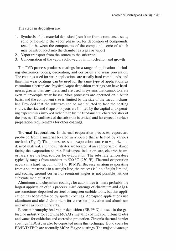
Chapter 7: Finishing and Coating / 361
the steps in deposition are:
1. Synthesis of the material deposited (transition from a condensed state, solid or liquid, to the vapor phase, or, for deposition of compounds, reaction between the components of the compound, some of which may be introduced into the chamber as a gas or vapor)
2. Vapor transport from the source to the substrate3. Condensation of the vapors followed by film nucleation and growth
the PVd process produces coatings for a range of applications includ-ing electronics, optics, decoration, and corrosion and wear prevention. the coatings used for wear applications are usually hard compounds, and thin-film wear coatings can be used for the same type of applications as chromium electroplate. Physical vapor deposition coatings can have hard-nesses greater than any metal and are used in systems that cannot tolerate even microscopic wear losses. Most processes are operated on a batch basis, and the component size is limited by the size of the vacuum cham-ber. Provided that the substrate can be manipulated to face the coating source, the size and shape of objects are limited by the capital and operat-ing expenditures involved rather than by the fundamental characteristics of the process. Cleanliness of the substrate is critical and far exceeds surface preparation requirements for other coatings.
Thermal Evaporation. in thermal evaporation processes, vapors are produced from a material located in a source that is heated by various methods (fig. 9). the process uses an evaporation source to vaporize the desired material, and the substrates are located at an appropriate distance facing the evaporation source. Resistance, induction, arc, electron beam, or lasers are the heat sources for evaporation. The substrate temperature typically ranges from ambient to 500 °C (930 °F). Thermal evaporation occurs in a hard vacuum of 0.1 to 10 MPa. Because an atom evaporating from a source travels in a straight line, the process is line-of-sight limited, and coating around corners or reentrant angles is not possible without substrate manipulation.
Aluminum and chromium coatings for automotive trim are probably the largest application of this process. hard coatings of chromium and al2o3 are sometimes deposited on steel or tungsten-carbide tools, but this appli-cation has been replaced by sputter coatings. Aerospace applications use aluminum and nickel-chromium for corrosion protection and aluminum and silver as solid lubricants.
Electron beam/physical vapor deposition (EB/PVD) is used in the gas turbine industry for applying MCrAlY metallic coatings on turbine blades and vanes for oxidation and corrosion protection. Zirconia thermal barrier coatings (TBCs) can also be deposited using this technique. Bond coats for EB/PVD TBCs are normally MCrAlY-type coatings. The major advantage
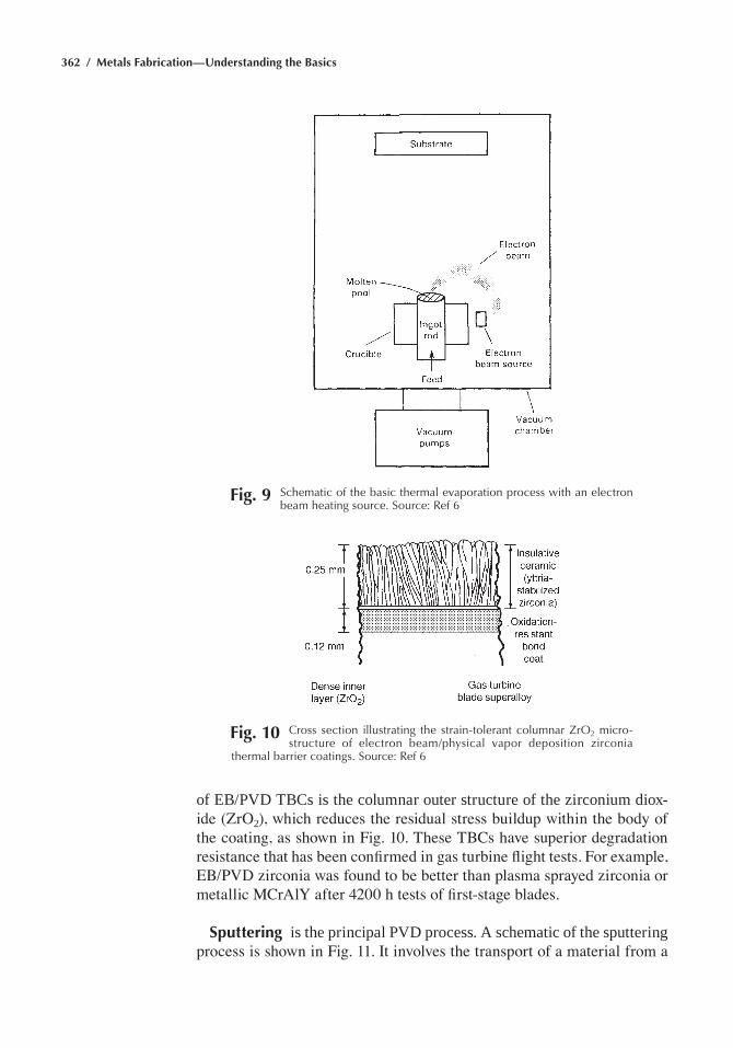
362 / Metals Fabrication—Understanding the Basics
of eB/PVd tBcs is the columnar outer structure of the zirconium diox-ide (ZrO2), which reduces the residual stress buildup within the body of the coating, as shown in Fig. 10. These TBCs have superior degradation resistance that has been confirmed in gas turbine flight tests. For example, EB/PVD zirconia was found to be better than plasma sprayed zirconia or metallic MCrAlY after 4200 h tests of first-stage blades.
Sputtering is the principal PVd process. a schematic of the sputtering process is shown in Fig. 11. It involves the transport of a material from a
Fig. 9 Schematic of the basic thermal evaporation process with an electron beam heating source. Source: ref 6
Fig. 10 Cross section illustrating the strain-tolerant columnar ZrO2 micro-structure of electron beam/physical vapor deposition zirconia
thermal barrier coatings. Source: ref 6
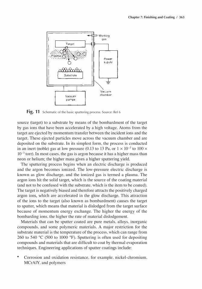
Chapter 7: Finishing and Coating / 363
source (target) to a substrate by means of the bombardment of the target by gas ions that have been accelerated by a high voltage. Atoms from the target are ejected by momentum transfer between the incident ions and the target. These ejected particles move across the vacuum chamber and are deposited on the substrate. In its simplest form, the process is conducted in an inert (noble) gas at low pressure (0.13 to 13 Pa, or 1 ¥ 10–3 to 100 ¥ 10–3 torr). In most cases, the gas is argon because it has a higher mass than neon or helium; the higher mass gives a higher sputtering yield.
The sputtering process begins when an electric discharge is produced and the argon becomes ionized. The low-pressure electric discharge is known as glow discharge, and the ionized gas is termed a plasma. The argon ions hit the solid target, which is the source of the coating material (and not to be confused with the substrate, which is the item to be coated). The target is negatively biased and therefore attracts the positively charged argon ions, which are accelerated in the glow discharge. this attraction of the ions to the target (also known as bombardment) causes the target to sputter, which means that material is dislodged from the target surface because of momentum energy exchange. The higher the energy of the bombarding ions, the higher the rate of material dislodgement.
Materials that can be sputter coated are pure metals, alloys, inorganic compounds, and some polymeric materials. A major restriction for the substrate material is the temperature of the process, which can range from 260 to 540 °C (500 to 1000 °F). Sputtering is often used for depositing compounds and materials that are difficult to coat by thermal evaporation techniques. engineering applications of sputter coatings include:
• Corrosion and oxidation resistance, for example, nickel-chromium, MCrAlY, and polymers
Fig. 11 Schematic of the basic sputtering process. Source: ref 6
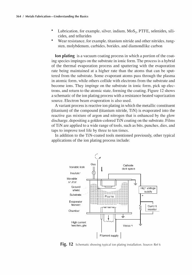
364 / Metals Fabrication—Understanding the Basics
• Lubrication, for example, silver, indium, MoS2, Ptfe, selenides, sili-cides, and tellurides
• Wear resistance, for example, titanium nitride and other nitrides, tung-sten, molybdenum, carbides, borides, and diamondlike carbon
Ion plating is a vacuum coating process in which a portion of the coat-ing species impinges on the substrate in ionic form. The process is a hybrid of the thermal evaporation process and sputtering with the evaporation rate being maintained at a higher rate than the atoms that can be sput-tered from the substrate. Some evaporant atoms pass through the plasma in atomic form, while others collide with electrons from the substrate and become ions. They impinge on the substrate in ionic form, pick up elec-trons, and return to the atomic state, forming the coating. Figure 12 shows a schematic of the ion plating process with a resistance heated vaporization source. Electron beam evaporation is also used.
a variant process is reactive ion plating in which the metallic constituent (titanium) of the compound (titanium nitride, tin) is evaporated into the reactive gas mixture of argon and nitrogen that is enhanced by the glow discharge, depositing a golden-colored TiN coating on the substrate. Films of TiN are applied to a wide range of tools, such as bits, punches, dies, and taps to improve tool life by three to ten times.
in addition to the tin-coated tools mentioned previously, other typical applications of the ion plating process include:
Fig. 12 Schematic showing typical ion plating installation. Source: ref 6
Chapter 7: Finishing and Coating / 365
• Good adhesion between a film and substrate (for example, silver on steel for mirrors, silver on beryllium for diffusion bonding)
• electrical conductive layers (aluminum, silver, and gold) on plastics and semiconductors
• Low-shear solid-film lubricants (for example, silver and gold)• decorative coatings (tin yields gold-colored deposit, ticxny yields
rose-colored deposit, TiC yields black deposit, zirconium nitride, ZrN, yields brass-colored deposit) applied to hardware, jewelry, guns, and cutlery
• corrosion protection: aluminum on uranium, steel (replacing cad-mium), and titanium; and carbon and tantalum on biological implants
• Deposition of electrically conductive diffusion barriers (for example, hafnium nitride, hfn, and tin on semiconductor devices)
Ion Implantation
Ion implantation involves the bombardment of a solid material with medium- to high-energy ionized atoms and offers the ability to alloy vir-tually any elemental species into the near-surface region of any substrate. the advantage is that it produces improved surface properties without the limitations of dimensional changes or delamination found in conventional coatings. disadvantages of the process include shallow penetration depths (on the order of a few hundred angstroms) and relatively high capital and operating costs. ion implantation is commercially applied to various steels, tungsten carbide/cobalt materials, and alloys of titanium, nickel, cobalt, aluminum, and chromium, although applications are restricted to tempera-tures below 250 °C (480 °F) for steels and 450 °C (840 °F) for carbides.
Some of the applications for the ion-implantation process are listed in Table 11. Ion-implantation surfaces produce exceptional results in reduc-ing wear, friction, and corrosion. commercial applications are tooling, bearings, and biomedical components. Nitrogen implantation, especially in alloy surfaces containing elements forming stable nitrides, is used for tools and dies, such as cobalt-cemented tungsten-carbide wire-drawing inserts. Nitrogen implantation has been especially successful in increas-ing the life (up to 20 times) of tools and parts used in the manufacture of injection molded plastics. Titanium and cobalt-chromium alloy orthopedic prostheses for hip and knee joints are among the most successful com-mercial applications for ion-implantation components for wear resistance.
Painting
Painting is the application of a thin organic coating to the surface of a material for decorative, protective, or functional purposes. the general terms paint and organic coating are essentially interchangeable and are
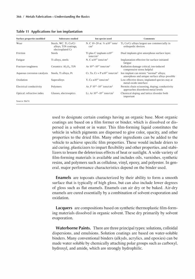
366 / Metals Fabrication—Understanding the Basics
used to designate certain coatings having an organic base. Most organic coatings are based on a film former or binder, which is dissolved or dis-persed in a solvent or in water. This film-forming liquid constitutes the vehicle in which pigments are dispersed to give color, opacity, and other properties to the dried film. Many other ingredients can be added to the vehicle to achieve specific film properties. These would include driers to aid curing, plasticizers to impart flexibility and other properties, and stabi-lizers to lessen the deleterious effects of heat or sunlight. a wide variety of film-forming materials is available and includes oils, varnishes, synthetic resins, and polymers such as cellulose, vinyl, epoxy, and polyester. in gen-eral, major performance characteristics depend on the binder used.
Enamels are topcoats characterized by their ability to form a smooth surface that is typically of high gloss, but can also include lower degrees of gloss such as flat enamels. Enamels can air dry or be baked. Air-dry enamels are cured essentially by a combination of solvent evaporation and oxidation.
Lacquers are compositions based on synthetic thermoplastic film-form-ing materials dissolved in organic solvent. These dry primarily by solvent evaporation.
Waterborne Paints. there are three principal types: solutions, colloidal dispersions, and emulsions. Solution coatings are based on water-soluble binders. Many conventional binders (alkyds, acrylics, and epoxies) can be made water soluble by chemically attaching polar groups such as carboxyl, hydroxyl, and amide, which are strongly hydrophilic.
Table 11 Applications for ion implantation
Surface properties modified Substrates studied Ion species used Comments
Wear Steels, WC, Ti, Co/Cr alloys, tin coatings, electroplated cr
N, C 10–20 at. % ≥1017 ions/cm2
ti, co/cr alloys largest use commercially in orthopedic devices
friction Steels Ti plus C implants ≥1017 ions/cm2
dual implants give amorphous surface layer.
fatigue ti alloys, steels N, C ≥1017 ions/cm2 implantation effective for surface initiated fatigue
fracture toughness ceramics: al2o3, tin Ar 1015–1017 ions/cm2 radiation damage critical; ion-induced compressive stress helpful
aqueous corrosion catalysis Steels, ti alloys, Pt Cr, Ta, Cr + P ≥1017 ions/cm2 ion implant can mimic “normal” alloys; amorphous and unique surface alloys possible
oxidation Superalloys Y, Ce ≥1015 ions/cm2 Low effective doses; implanted species stay at metal-oxide interface
electrical conductivity Polymers Ar, F 1015–1017 ions/cm2 Permits chain scissoning, doping; conductivity approaches disordered metal levels
optical: refractive index glasses, electrooptics Li, Ar 1015–1017 ions/cm2 Chemical doping and lattice disorder both important
Source: ref 6
Chapter 7: Finishing and Coating / 367
Electrophoretic paints are special water-reducible paints. Resin and pigment materials are shipped and stored as concentrates to be added to the production tank as needed. Electrophoretic films are always depos-ited from a dip tank. The operating bath consists of a resin concentrate and pigment concentrate mixed with deionized water and small amounts of solubilizers and defoamers. The concentration of nonvolatile solids in the bath varies from approximately 10 to 20%, depending on type and composition.
Autophoretic paints are water-reducible paints deposited on metal surfaces by the catalytic action of the metal on the paint materials in the bath. Currently, only ferrous surfaces that activate the autophoretic paints are available commercially. Tubular automotive frames are coated by this method because the entire length of the tubing can be coated inside and outside with equal ease.
High-solids paints contain 50% or more solids by volume. One method of obtaining high-solids paints is to use lower-molecular-weight poly-mers, which require less solvent to attain the desired application viscosity. Another method of reducing viscosity of high-solids paints is by heating the paint material to a temperature of approximately 32 to 52 °C (90 to 125 °F). Many two-component systems use a catalyst to increase the rate of the curing reaction. fast-reacting, two-component systems are usually applied with special spray guns that mix the two components at the spray nozzle.
Selection of a Paint System
Although a wide variety of coatings are available, the ideal coating system—one with all desired performance properties, simple applica-tion, and low cost—is difficult to find. Factors such as regulations, service environment, substrate and service conditions, basic function, application limitations, and cost usually must be compromised.
Service Environment. in selection of a paint system, many factors concerning service environment must be considered. Needs are different for interior and exterior coatings. The specific properties needed, such as resistance to heat, cold, sunlight, and weathering, must be determined. If the coating needs to be resistant to chemicals, the specific chemical, such as acid, alkali, solvent, or water immersion, should be specified. Mechani-cal properties required, including hardness, flexibility, impact resistance, and abrasion resistance, should also be determined.
corrosion of steel and cast iron occurs in all environments. the rate and extent of corrosion vary from mild attack in dry, clean environments to highly accelerated attack in marine or industrial areas where corrosive
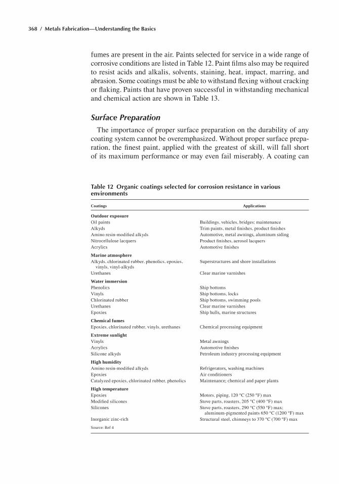
368 / Metals Fabrication—Understanding the Basics
fumes are present in the air. Paints selected for service in a wide range of corrosive conditions are listed in Table 12. Paint films also may be required to resist acids and alkalis, solvents, staining, heat, impact, marring, and abrasion. Some coatings must be able to withstand flexing without cracking or flaking. Paints that have proven successful in withstanding mechanical and chemical action are shown in Table 13.
Surface Preparation
The importance of proper surface preparation on the durability of any coating system cannot be overemphasized. Without proper surface prepa-ration, the finest paint, applied with the greatest of skill, will fall short of its maximum performance or may even fail miserably. A coating can
Table 12 Organic coatings selected for corrosion resistance in various environments
Coatings Applications
Outdoor exposureoil paints Buildings, vehicles, bridges; maintenanceAlkyds Trim paints, metal finishes, product finishesAmino resin-modified alkyds automotive, metal awnings, aluminum sidingnitrocellulose lacquers Product finishes, aerosol lacquersacrylics Automotive finishes
Marine atmosphereAlkyds, chlorinated rubber, phenolics, epoxies,
vinyls, vinyl-alkydsSuperstructures and shore installations
urethanes clear marine varnishes
Water immersionPhenolics Ship bottomsVinyls Ship bottoms, locksChlorinated rubber Ship bottoms, swimming poolsurethanes clear marine varnishesepoxies Ship hulls, marine structures
Chemical fumesEpoxies, chlorinated rubber, vinyls, urethanes chemical processing equipment
Extreme sunlightVinyls Metal awningsacrylics Automotive finishesSilicone alkyds Petroleum industry processing equipment
High humidityAmino resin-modified alkyds refrigerators, washing machinesepoxies air conditionersCatalyzed epoxies, chlorinated rubber, phenolics Maintenance; chemical and paper plants
High temperatureepoxies Motors, piping, 120 °C (250 °F) maxModified silicones Stove parts, roasters, 205 °C (400 °F) maxSilicones Stove parts, roasters, 290 °C (550 °F) max;
aluminum-pigmented paints 650 °C (1200 °F) maxinorganic zinc-rich Structural steel, chimneys to 370 °C (700 °F) max
Source: ref 4
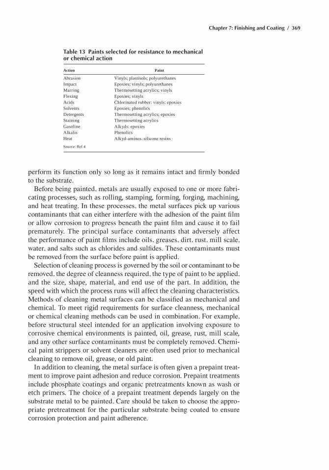
Chapter 7: Finishing and Coating / 369
perform its function only so long as it remains intact and firmly bonded to the substrate.
Before being painted, metals are usually exposed to one or more fabri-cating processes, such as rolling, stamping, forming, forging, machining, and heat treating. In these processes, the metal surfaces pick up various contaminants that can either interfere with the adhesion of the paint film or allow corrosion to progress beneath the paint film and cause it to fail prematurely. the principal surface contaminants that adversely affect the performance of paint films include oils, greases, dirt, rust, mill scale, water, and salts such as chlorides and sulfides. These contaminants must be removed from the surface before paint is applied.
Selection of cleaning process is governed by the soil or contaminant to be removed, the degree of cleanness required, the type of paint to be applied, and the size, shape, material, and end use of the part. in addition, the speed with which the process runs will affect the cleaning characteristics. Methods of cleaning metal surfaces can be classified as mechanical and chemical. to meet rigid requirements for surface cleanness, mechanical or chemical cleaning methods can be used in combination. For example, before structural steel intended for an application involving exposure to corrosive chemical environments is painted, oil, grease, rust, mill scale, and any other surface contaminants must be completely removed. Chemi-cal paint strippers or solvent cleaners are often used prior to mechanical cleaning to remove oil, grease, or old paint.
in addition to cleaning, the metal surface is often given a prepaint treat-ment to improve paint adhesion and reduce corrosion. Prepaint treatments include phosphate coatings and organic pretreatments known as wash or etch primers. the choice of a prepaint treatment depends largely on the substrate metal to be painted. Care should be taken to choose the appro-priate pretreatment for the particular substrate being coated to ensure corrosion protection and paint adherence.
Table 13 Paints selected for resistance to mechanical or chemical action
Action Paint
Abrasion Vinyls; plastisols; polyurethanesimpact epoxies; vinyls; polyurethanesMarring thermosetting acrylics; vinylsflexing epoxies; vinylsacids Chlorinated rubber; vinyls; epoxiesSolvents epoxies; phenolicsdetergents thermosetting acrylics; epoxiesStaining thermosetting acrylicsgasoline Alkyds; epoxiesAlkalis Phenolicsheat Alkyd-amines, silicone resins
Source: ref 4
370 / Metals Fabrication—Understanding the Basics
Paint Application Methods
Spraying is adaptable to either large- or low-volume production. Appli-cations can be limited because of solvent emissions, possible fire hazards, or potential damage from overspray. Spraying methods include conven-tional air spraying, in which the paint is atomized and propelled against the work by means of compressed air, hot spraying, hydraulic airless spraying, and air and airless electrostatic spraying.
hot spraying is a method in which air-atomized spraying equipment is used in conjunction with a heat exchanger to heat the paint to a predeter-mined temperature. the temperature range for hot spraying is usually from 60 to 82 °C (140 to 180 °F). In air-atomized spraying, viscosities suitable for application are obtained with the use of solvents. The hot spraying method uses heat to lower the viscosity to the optimal range for spraying, allowing application of paint with higher solids content.
airless spraying, with either heated or unheated paint, uses hydraulic (pumping) pressure to propel the paint through the hoses and atomizing nozzle. the main advantages of airless spray painting stem from the elimi-nation of air as the force for atomizing and propelling the paint. airless spraying requires the release of considerably less energy at the nozzle, and overspray is minimized.
in electrostatic spray painting, electrically charged atomized particles of paint are attracted to the grounded part. Paint for electrostatic applications can be atomized by conventional air, airless, or rotational techniques. One of the chief advantages of electrostatic spraying is the small loss of paint from overspray. Whereas in conventional spray painting as much as 70% of the paint sprayed may be lost because of overspray, as little as 10% may be lost in electrostatic spraying. Another advantage is the ability to produce a consistent paint film over a long production run. The main disadvantage is that the electrostatic attraction of the part for the paint draws the paint to the nearest edge or surface of the part, and it is difficult or impossible to get paint into deep recesses, corners, and shielded areas.
Dip painting consists of submerging a part in paint contained in a tank, withdrawing the part, and permitting the excess paint to drain off. Parts with complex surfaces can be coated efficiently by dipping. Larger parts, produced in quantity, are racked or hung on conveyors, which carry the parts to the paint tank, automatically immerse and withdraw the parts, and carry them over drip troughs into which the excess paint runs off. dip painting is seldom used where uniformity of paint thickness is required. This procedure may be unsatisfactory for painting parts having machined holes or surfaces where masking is impractical. Usually, paint films applied by dipping are heavier at the bottom than at the top, because of paint runoff, and are thin at sharp edges. In addition, bubbles and bumps may be found at the bottom edges of painted pieces. Parts can be dip painted
Chapter 7: Finishing and Coating / 371
to obtain complete coverage and then spray painted to obtain a required surface appearance.
In flow coating, paint is pumped from a storage tank through prop-erly positioned nozzles, onto all surfaces of parts, as they are conveyed. Excess paint drains back into the storage tank for recirculation. Paint films applied by flow coating are wedge shaped and are thinner at the top and thicker at the bottom of the painted part. In flow coating, utilization of paint approaches 95% as opposed to approximately 50% for atomized air spraying and 70 to 80% for dipping. Properly designed flow coating machines with vapor chamber flowout reduce solvent losses and eliminate tears, sags, and curtains. flow coating is used extensively to paint panels for home appliances. flow coating is also used to coat parts with recesses inaccessible to spraying, to coat parts (such as bedsprings) for which good appearance is desirable but is secondary to complete coverage and econom-ical application, and to coat intricate parts that are too open in design to permit efficient spray painting and too large to be practical for dip painting.
Other painting methods include roller coating, curtain coating, tumble or barrel coating, electrocoating, and powder coating.
ACKNOWLEDGMENT
this chapter was adapted from the section Surface engineering in ASM Handbook Desk Edition, 2nd ed., ASM International, 1998.
REFERENCES
1. D.B. Chalk, Classification and Selection of Cleaning Processes, Sur-face Engineering, Vol 5, ASM Handbook, ASM International, 1994
2. finishing Methods, ASM Handbook Desk Edition, 2nd ed., aSM International, 1998
3. electrodeposition Processes, ASM Handbook Desk Edition, 2nd ed., ASM International, 1998
4. dip, Barrier, and chemical conversion coatings, ASM Handbook Desk Edition, 2nd ed., ASM International, 1998
5. chemical Vapor deposition and related Processes, ASM Handbook Desk Edition, 2nd ed., ASM International, 1998
6. Physical Vapor deposition, ASM Handbook Desk Edition, 2nd ed., ASM International, 1998
SELECTED REFERENCES• corrosion Protection Methods, Corrosion, Vol 13, ASM Handbook,
ASM International, 1987• design for Surface finishing, Materials Selection and Design, Vol 20,
ASM Handbook, ASM International, 1997, p 820–827
372 / Metals Fabrication—Understanding the Basics
• L.J. durney, ed., Electroplating Engineering Handbook, 4th ed., Van Nostrand Reinhold, 1984
• effects of Surface treatments on Materials Performance, Materials Selection and Design, Vol 20, ASM Handbook, aSM international, 1997, p 470–490
• J.d. Keane, ed., Steel Structures Painting Manual, Steel Structures Painting Council, 1989
• G.O. Mallory and J.B. Hajdu, Ed., Electroless Plating: Fundamentals and Applications, American Electroplaters Society, 1990
• c.g. Munger, Corrosion Prevention by Protective Coatings, national Association of Corrosion Engineers, 1985
• S.M. Rossnagel, J.J. Cuomo, and W. Westwood, Ed., Handbook of Plasma Processing Technology: Fundamentals, Etching, Deposition, and Surface Interactions, Noyes Publications, 1990
• W.A. Safranek, The Properties of Electrodeposited Metals and Alloys: A Handbook, 2nd ed., american electroplaters and Surface finishers Society, 1986
• K.K. Shuegrat, ed., Handbook of Thin Film Deposition Processes and Techniques, Noyes Publications, 1988
• K.h. Stern, ed., Metallurgical and Ceramic Protective Coatings, Chapman and Hall, 1996
• Surface Engineering, Vol 5, ASM Handbook, ASM International, 1994• Surface Treatments and Coatings for Friction and Wear Control, Fric-
tion, Lubrication, and Wear Technology, Vol 18, ASM Handbook, ASM International, 1992
Copyright © 2013 ASM International®
All rights reservedwww.asminternational.org
Metals Fabrication—Understanding the BasicsF.C. Campbell, editor
Chapter 8Powder Metallurgy
POWDER METALLURGY (P/M) is the process of blending fine pow-dered materials, pressing (compacting) them into a desired shape or form, and then heating the compressed material in a controlled atmosphere to bond the material together (sintering). The P/M process generally consists of four basic steps: powder manufacture, powder blending, compacting, and sintering. Compacting is generally performed at room temperature, and the elevated-temperature process of sintering is usually conducted at atmospheric pressure. Optional secondary processing is often used to obtain special properties or enhanced precision.
The P/M process offers a number of advantages over other metalworking processes, including:
• Elimination or reduction of machining (near-net or net shape parts)• High production rates• Complex shapes• Wide variations in compositions• Wide property variations• Elimination or reduction of scrap
Disadvantages of P/M include:
• Inferior strength properties• High tooling costs• High material cost• Size and shape limitations• Dimensional changes during sintering• Density variations• Health and safety hazards
Powder metallurgy products are used in a wide range of industries, from automotive and aerospace applications to power tools and household appli-ances. The predominant market for P/M structural parts is the automotive
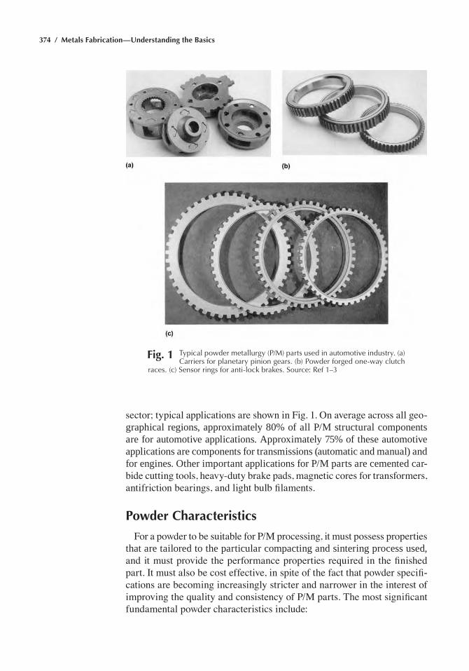
374 / Metals Fabrication—Understanding the Basics
sector; typical applications are shown in Fig. 1. On average across all geo-graphical regions, approximately 80% of all P/M structural components are for automotive applications. Approximately 75% of these automotive applications are components for transmissions (automatic and manual) and for engines. Other important applications for P/M parts are cemented car-bide cutting tools, heavy-duty brake pads, magnetic cores for transformers, antifriction bearings, and light bulb filaments.
Powder Characteristics
For a powder to be suitable for P/M processing, it must possess properties that are tailored to the particular compacting and sintering process used, and it must provide the performance properties required in the finished part. It must also be cost effective, in spite of the fact that powder specifi-cations are becoming increasingly stricter and narrower in the interest of improving the quality and consistency of P/M parts. The most significant fundamental powder characteristics include:
Fig. 1 typical powder metallurgy (p/M) parts used in automotive industry. (a) Carriers for planetary pinion gears. (b) powder forged one-way clutch
races. (c) Sensor rings for anti-lock brakes. Source: ref 1–3
Chapter 8: Powder Metallurgy / 375
• Particle size• Particle size distribution• Particle shape• Powder purity
Particle Size. Powders suitable for conventional P/M processing are typically –80 mesh powders, that is, powders with an upper particle size of approximately 177 mm (7 mils). This upper particle size limit is required to produce porous sintered parts that have a pleasing surface texture and to assure adequate mechanical properties. Also, many powders are mix-tures of several components that alloy with each other during sintering by solid-state diffusion. In the presence of large particles, the sintering times of such systems would be unacceptably long.
The lower end of the particle size spectrum of typical P/M powders is approximately 1 mm (0.04 mils). Most P/M powders have –325 mesh (<44 mm or 1.7 mils) fractions not exceeding 30 to 40%. These requirements are dictated by the need of a powder to flow freely, or by gravity, from a storage hopper into the die in an automated compacting press. With decreasing particle size, increasing amounts of fines (–325 mesh), and with more irregular particle shapes, powder flowability deteriorates. Moderate amounts of fines also provide for a good balance between sintering speed and shrinkage during sintering.
Particle Size Distribution. In between the limits of coarse and fine, most P/M powders have particle size distributions consisting of more or less evenly weighted intermediate-size powder fractions. For most P/M uses, the actual numbers of these fractions are less important than their consistency from powder lot to powder lot.
Lubricants. Powders used in the press and sinter process typically contain 0.5 to 1.5% of an admixed lubricant that reduces friction during pressing, facilitates compaction and ejection, and lengthens the compac-tion die life. Widely used lubricants include stearic acid, synthetic waxes, zinc stearate, lithium stearate, and mixtures of these. The addition of a lubricant to a powder affects many of its engineering properties, includ-ing powder flow, apparent density, green strength, and compressibility. Lubricant optimization usually consists of identifying the composition and amount of lubricant providing the smallest loss of green strength for a given reduction in friction. Lubricants volatilize and decompose during sintering.
Coarse and Fine Powders. Some P/M processes employ finer or coarser powders than those used in conventional pressing and sintering. Powder injection molding (PIM) works best using powders with particle sizes up to approximately 20 mm (0.8 mils). The small powder particles,
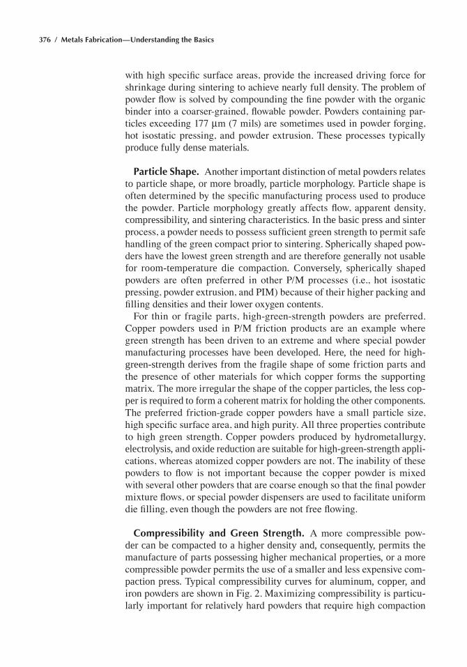
376 / Metals Fabrication—Understanding the Basics
with high specific surface areas, provide the increased driving force for shrinkage during sintering to achieve nearly full density. The problem of powder flow is solved by compounding the fine powder with the organic binder into a coarser-grained, flowable powder. Powders containing par-ticles exceeding 177 mm (7 mils) are sometimes used in powder forging, hot isostatic pressing, and powder extrusion. These processes typically produce fully dense materials.
Particle Shape. Another important distinction of metal powders relates to particle shape, or more broadly, particle morphology. Particle shape is often determined by the specific manufacturing process used to produce the powder. Particle morphology greatly affects flow, apparent density, compressibility, and sintering characteristics. In the basic press and sinter process, a powder needs to possess sufficient green strength to permit safe handling of the green compact prior to sintering. Spherically shaped pow-ders have the lowest green strength and are therefore generally not usable for room-temperature die compaction. Conversely, spherically shaped powders are often preferred in other P/M processes (i.e., hot isostatic pressing, powder extrusion, and PIM) because of their higher packing and filling densities and their lower oxygen contents.
For thin or fragile parts, high-green-strength powders are preferred. Copper powders used in P/M friction products are an example where green strength has been driven to an extreme and where special powder manufacturing processes have been developed. Here, the need for high-green-strength derives from the fragile shape of some friction parts and the presence of other materials for which copper forms the supporting matrix. The more irregular the shape of the copper particles, the less cop-per is required to form a coherent matrix for holding the other components. The preferred friction-grade copper powders have a small particle size, high specific surface area, and high purity. All three properties contribute to high green strength. Copper powders produced by hydrometallurgy, electrolysis, and oxide reduction are suitable for high-green-strength appli-cations, whereas atomized copper powders are not. The inability of these powders to flow is not important because the copper powder is mixed with several other powders that are coarse enough so that the final powder mixture flows, or special powder dispensers are used to facilitate uniform die filling, even though the powders are not free flowing.
Compressibility and Green Strength. A more compressible pow-der can be compacted to a higher density and, consequently, permits the manufacture of parts possessing higher mechanical properties, or a more compressible powder permits the use of a smaller and less expensive com-paction press. Typical compressibility curves for aluminum, copper, and iron powders are shown in Fig. 2. Maximizing compressibility is particu-larly important for relatively hard powders that require high compaction
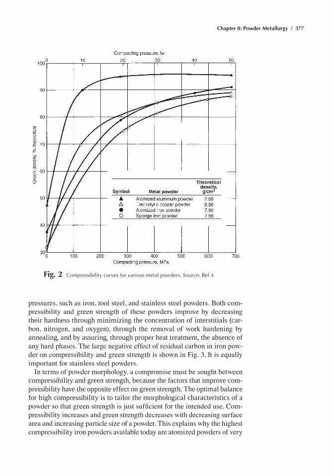
Chapter 8: Powder Metallurgy / 377
pressures, such as iron, tool steel, and stainless steel powders. Both com-pressibility and green strength of these powders improve by decreasing their hardness through minimizing the concentration of interstitials (car-bon, nitrogen, and oxygen), through the removal of work hardening by annealing, and by assuring, through proper heat treatment, the absence of any hard phases. The large negative effect of residual carbon in iron pow-der on compressibility and green strength is shown in Fig. 3. It is equally important for stainless steel powders.
In terms of powder morphology, a compromise must be sought between compressibility and green strength, because the factors that improve com-pressibility have the opposite effect on green strength. The optimal balance for high compressibility is to tailor the morphological characteristics of a powder so that green strength is just sufficient for the intended use. Com-pressibility increases and green strength decreases with decreasing surface area and increasing particle size of a powder. This explains why the highest compressibility iron powders available today are atomized powders of very
Fig. 2 Compressibility curves for various metal powders. Source: ref 4
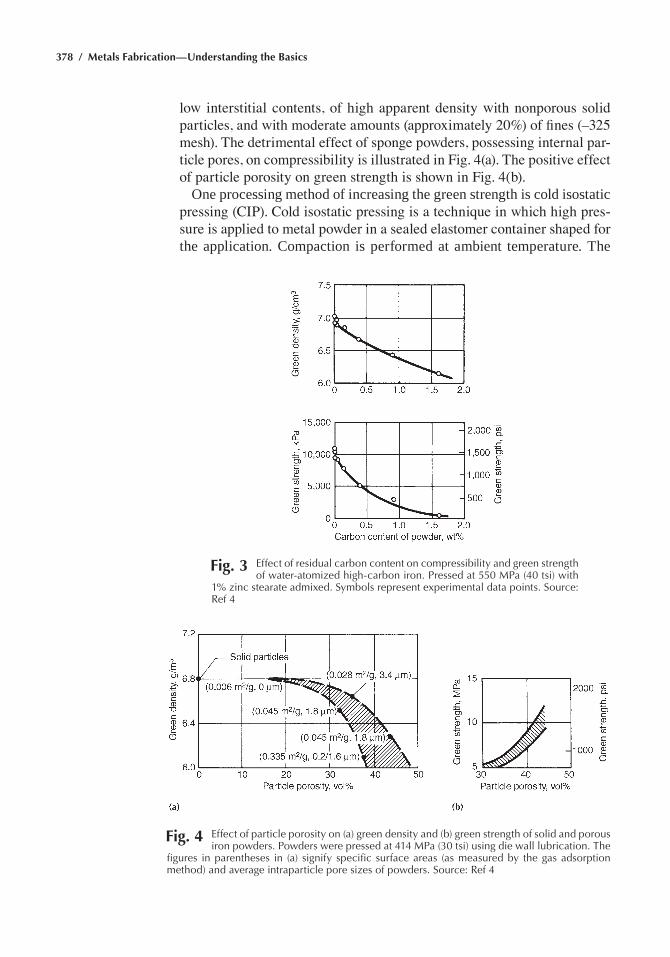
378 / Metals Fabrication—Understanding the Basics
low interstitial contents, of high apparent density with nonporous solid particles, and with moderate amounts (approximately 20%) of fines (–325 mesh). The detrimental effect of sponge powders, possessing internal par-ticle pores, on compressibility is illustrated in Fig. 4(a). The positive effect of particle porosity on green strength is shown in Fig. 4(b).
One processing method of increasing the green strength is cold isostatic pressing (CIP). Cold isostatic pressing is a technique in which high pres-sure is applied to metal powder in a sealed elastomer container shaped for the application. Compaction is performed at ambient temperature. The
Fig. 3 effect of residual carbon content on compressibility and green strength of water-atomized high-carbon iron. pressed at 550 Mpa (40 tsi) with
1% zinc stearate admixed. Symbols represent experimental data points. Source: ref 4
Fig. 4 effect of particle porosity on (a) green density and (b) green strength of solid and porous iron powders. powders were pressed at 414 Mpa (30 tsi) using die wall lubrication. the
figures in parentheses in (a) signify specific surface areas (as measured by the gas adsorption method) and average intraparticle pore sizes of powders. Source: ref 4
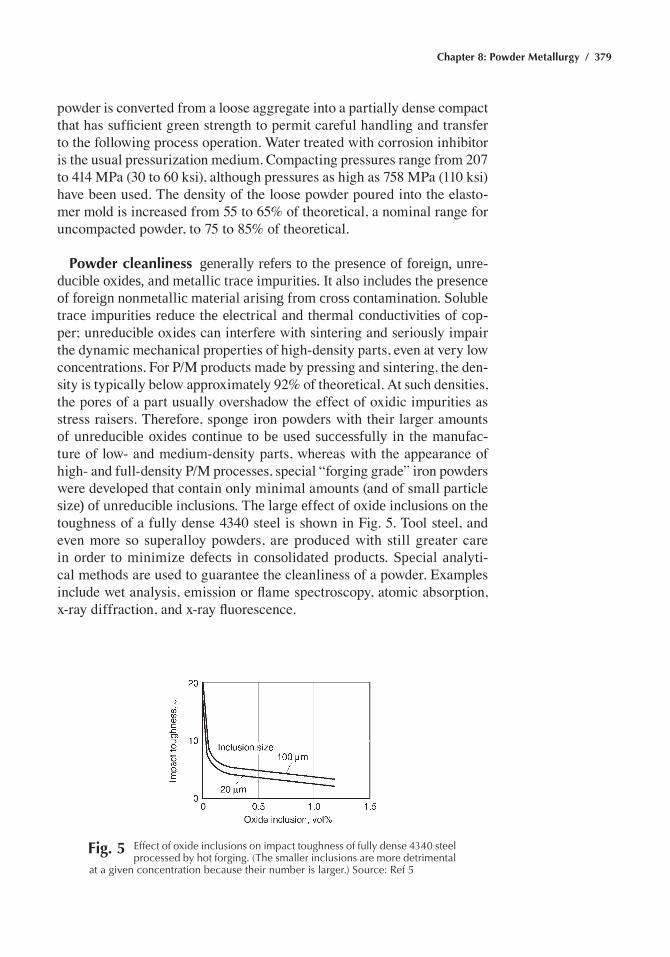
Chapter 8: Powder Metallurgy / 379
powder is converted from a loose aggregate into a partially dense compact that has sufficient green strength to permit careful handling and transfer to the following process operation. Water treated with corrosion inhibitor is the usual pressurization medium. Compacting pressures range from 207 to 414 MPa (30 to 60 ksi), although pressures as high as 758 MPa (110 ksi) have been used. The density of the loose powder poured into the elasto-mer mold is increased from 55 to 65% of theoretical, a nominal range for uncompacted powder, to 75 to 85% of theoretical.
Powder cleanliness generally refers to the presence of foreign, unre-ducible oxides, and metallic trace impurities. It also includes the presence of foreign nonmetallic material arising from cross contamination. Soluble trace impurities reduce the electrical and thermal conductivities of cop-per; unreducible oxides can interfere with sintering and seriously impair the dynamic mechanical properties of high-density parts, even at very low concentrations. For P/M products made by pressing and sintering, the den-sity is typically below approximately 92% of theoretical. At such densities, the pores of a part usually overshadow the effect of oxidic impurities as stress raisers. Therefore, sponge iron powders with their larger amounts of unreducible oxides continue to be used successfully in the manufac-ture of low- and medium-density parts, whereas with the appearance of high- and full-density P/M processes, special “forging grade” iron powders were developed that contain only minimal amounts (and of small particle size) of unreducible inclusions. The large effect of oxide inclusions on the toughness of a fully dense 4340 steel is shown in Fig. 5. Tool steel, and even more so superalloy powders, are produced with still greater care in order to minimize defects in consolidated products. Special analyti-cal methods are used to guarantee the cleanliness of a powder. Examples include wet analysis, emission or flame spectroscopy, atomic absorption, x-ray diffraction, and x-ray fluorescence.
Fig. 5 effect of oxide inclusions on impact toughness of fully dense 4340 steel processed by hot forging. (the smaller inclusions are more detrimental
at a given concentration because their number is larger.) Source: ref 5
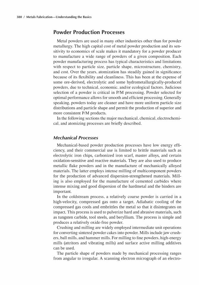
380 / Metals Fabrication—Understanding the Basics
Powder Production Processes
Metal powders are used in many other industries other than for powder metallurgy. The high capital cost of metal powder production and its sen-sitivity to economics of scale makes it mandatory for a powder producer to manufacture a wide range of powders of a given composition. Each powder manufacturing process has typical characteristics and limitations with respect to particle size, particle shape, microstructure, chemistry, and cost. Over the years, atomization has steadily gained in significance because of its flexibility and cleanliness. This has been at the expense of some ore-derived, electrolytic and some hydrometallurgically-produced powders, due to technical, economic, and/or ecological factors. Judicious selection of a powder is critical in P/M processing. Powder selected for optimal performance allows for smooth and efficient processing. Generally speaking, powders today are cleaner and have more uniform particle size distributions and particle shape and permit the production of superior and more consistent P/M products.
In the following sections the major mechanical, chemical, electrochemi-cal, and atomizing processes are briefly described.
Mechanical Processes
Mechanical-based powder production processes have low energy effi-ciency, and their commercial use is limited to brittle materials such as electrolytic iron chips, carbonized iron scarf, master alloys, and certain oxidation-sensitive and reactive materials. They are also used to produce metallic flake powders and in the manufacture of mechanically alloyed materials. The latter employs intense milling of multicomponent powders for the production of advanced dispersion-strengthened materials. Mill-ing is also employed for the manufacture of cemented carbides where intense mixing and good dispersion of the hardmetal and the binders are important.
In the coldstream process, a relatively coarse powder is carried in a high-velocity, compressed gas onto a target. Adiabatic cooling of the compressed gas cools and embrittles the metal so that it disintegrates on impact. This process is used to pulverize hard and abrasive materials, such as tungsten carbide, tool steels, and beryllium. The process is simple and produces a relatively oxide-free powder.
Crushing and milling are widely employed intermediate unit operations for converting sintered powder cakes into powder. Mills include jaw crush-ers, ball mills, and hammer mills. For milling to fine powders, high-energy mills (attritors and vibrating mills) and surface active milling additives can be used.
The particle shape of powders made by mechanical processing ranges from angular to irregular. A scanning electron micrograph of an electro-
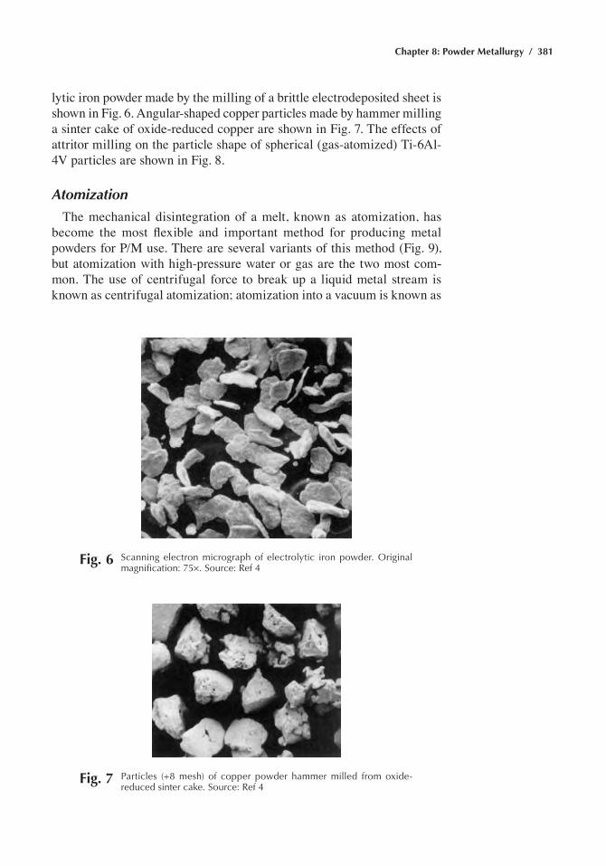
Chapter 8: Powder Metallurgy / 381
lytic iron powder made by the milling of a brittle electrodeposited sheet is shown in Fig. 6. Angular-shaped copper particles made by hammer milling a sinter cake of oxide-reduced copper are shown in Fig. 7. The effects of attritor milling on the particle shape of spherical (gas-atomized) Ti-6Al-4V particles are shown in Fig. 8.
Atomization
The mechanical disintegration of a melt, known as atomization, has become the most flexible and important method for producing metal powders for P/M use. There are several variants of this method (Fig. 9), but atomization with high-pressure water or gas are the two most com-mon. The use of centrifugal force to break up a liquid metal stream is known as centrifugal atomization; atomization into a vacuum is known as
Fig. 6 Scanning electron micrograph of electrolytic iron powder. Original magnification: 75¥. Source: ref 4
Fig. 7 particles (+8 mesh) of copper powder hammer milled from oxide-reduced sinter cake. Source: ref 4
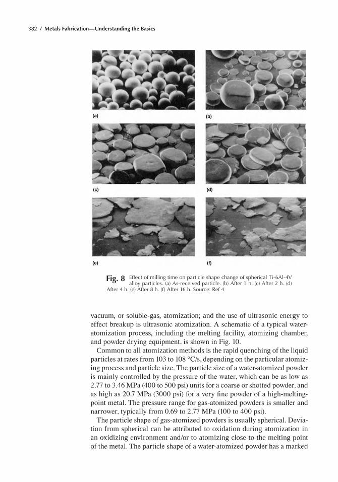
382 / Metals Fabrication—Understanding the Basics
Fig. 8 effect of milling time on particle shape change of spherical ti-6al-4V alloy particles. (a) as-received particle. (b) after 1 h. (c) after 2 h. (d)
after 4 h. (e) after 8 h. (f) after 16 h. Source: ref 4
vacuum, or soluble-gas, atomization; and the use of ultrasonic energy to effect breakup is ultrasonic atomization. A schematic of a typical water-atomization process, including the melting facility, atomizing chamber, and powder drying equipment, is shown in Fig. 10.
Common to all atomization methods is the rapid quenching of the liquid particles at rates from 103 to 108 °C/s, depending on the particular atomiz-ing process and particle size. The particle size of a water-atomized powder is mainly controlled by the pressure of the water, which can be as low as 2.77 to 3.46 MPa (400 to 500 psi) units for a coarse or shotted powder, and as high as 20.7 MPa (3000 psi) for a very fine powder of a high-melting-point metal. The pressure range for gas-atomized powders is smaller and narrower, typically from 0.69 to 2.77 MPa (100 to 400 psi).
The particle shape of gas-atomized powders is usually spherical. Devia-tion from spherical can be attributed to oxidation during atomization in an oxidizing environment and/or to atomizing close to the melting point of the metal. The particle shape of a water-atomized powder has a marked
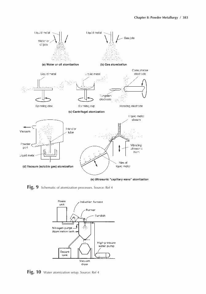
Chapter 8: Powder Metallurgy / 383
Fig. 9 Schematic of atomization processes. Source: ref 4
Fig. 10 Water atomization setup. Source: ref 4
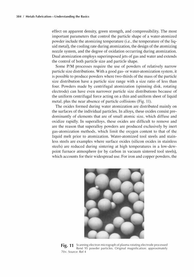
384 / Metals Fabrication—Understanding the Basics
effect on apparent density, green strength, and compressibility. The most important parameters that control the particle shape of a water-atomized powder include the atomizing temperature (i.e., the temperature of the liq-uid metal), the cooling rate during atomization, the design of the atomizing nozzle system, and the degree of oxidation occurring during atomization. Dual atomization employs superimposed jets of gas and water and extends the control of both particle size and particle shape.
Some P/M processes require the use of powders of relatively narrow particle size distributions. With a good gas- or water-atomization system, it is possible to produce powders where two-thirds of the mass of the particle size distribution have a particle size range with a size ratio of less than four. Powders made by centrifugal atomization (spinning disk, rotating electrode) can have even narrower particle size distributions because of the uniform centrifugal force acting on a thin and uniform sheet of liquid metal, plus the near absence of particle collisions (Fig. 11).
The oxides formed during water atomization are distributed mainly on the surfaces of the individual particles. In alloys, these oxides consist pre-dominantly of elements that are of small atomic size, which diffuse and oxidize rapidly. In superalloys, these oxides are difficult to remove and are the reason that superalloy powders are produced exclusively by inert gas-atomization methods, which limit the oxygen content to that of the liquid melt prior to atomization. Water-atomized tool steels and stain-less steels are examples where surface oxides (silicon oxides in stainless steels) are reduced during sintering at high temperatures in a low-dew-point furnace atmosphere (or by carbon in vacuum sintered tool steels), which accounts for their widespread use. For iron and copper powders, the
Fig. 11 Scanning electron micrograph of plasma rotating electrode processed rené 95 powder particles. Original magnification: approximately
70¥. Source: ref 4
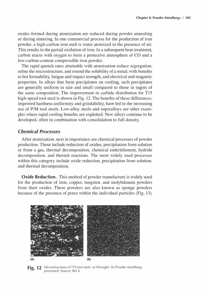
Chapter 8: Powder Metallurgy / 385
oxides formed during atomization are reduced during powder annealing or during sintering. In one commercial process for the production of iron powder, a high-carbon iron melt is water atomized in the presence of air. This results in the partial oxidation of iron. In a subsequent heat treatment, carbon reacts with oxygen to form a protective atmosphere of CO and a low-carbon-content compressible iron powder.
The rapid quench rates attainable with atomization reduce segregation, refine the microstructure, and extend the solubility of a metal, with benefits to hot formability, fatigue and impact strength, and electrical and magnetic properties. In alloys that form precipitates on cooling, such precipitates are generally uniform in size and small compared to those in ingots of the same composition. The improvement in carbide distribution for T15 high-speed tool steel is shown in Fig. 12. The benefits of these differences, improved hardness uniformity and grindability, have led to the increasing use of P/M tool steels. Low-alloy steels and superalloys are other exam-ples where rapid cooling benefits are exploited. New alloys continue to be developed, often in combination with consolidation to full density.
Chemical Processes
After atomization, next in importance are chemical processes of powder production. These include reduction of oxides, precipitation from solution or from a gas, thermal decomposition, chemical embrittlement, hydride decomposition, and thermit reactions. The most widely used processes within this category include oxide reduction, precipitation from solution, and thermal decomposition.
Oxide Reduction. This method of powder manufacture is widely used for the production of iron, copper, tungsten, and molybdenum powders from their oxides. These powders are also known as sponge powders because of the presence of pores within the individual particles (Fig. 13).
Fig. 12 Microstructures of t15 tool steel. (a) Wrought. (b) powder metallurgy processed. Source: ref 4
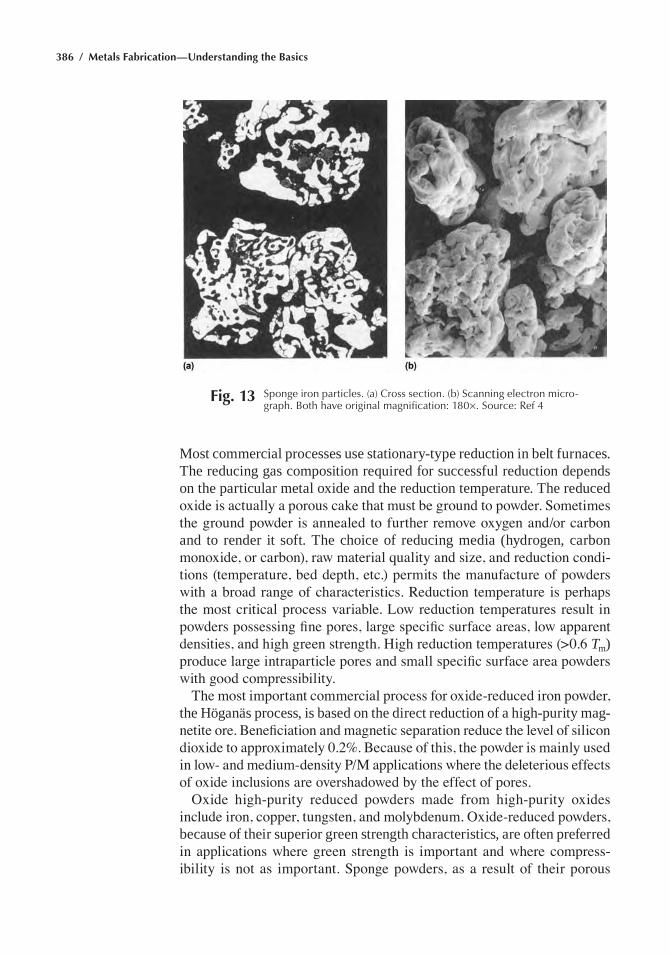
386 / Metals Fabrication—Understanding the Basics
Most commercial processes use stationary-type reduction in belt furnaces. The reducing gas composition required for successful reduction depends on the particular metal oxide and the reduction temperature. The reduced oxide is actually a porous cake that must be ground to powder. Sometimes the ground powder is annealed to further remove oxygen and/or carbon and to render it soft. The choice of reducing media (hydrogen, carbon monoxide, or carbon), raw material quality and size, and reduction condi-tions (temperature, bed depth, etc.) permits the manufacture of powders with a broad range of characteristics. Reduction temperature is perhaps the most critical process variable. Low reduction temperatures result in powders possessing fine pores, large specific surface areas, low apparent densities, and high green strength. High reduction temperatures (>0.6 Tm) produce large intraparticle pores and small specific surface area powders with good compressibility.
The most important commercial process for oxide-reduced iron powder, the Höganäs process, is based on the direct reduction of a high-purity mag-netite ore. Beneficiation and magnetic separation reduce the level of silicon dioxide to approximately 0.2%. Because of this, the powder is mainly used in low- and medium-density P/M applications where the deleterious effects of oxide inclusions are overshadowed by the effect of pores.
Oxide high-purity reduced powders made from high-purity oxides include iron, copper, tungsten, and molybdenum. Oxide-reduced powders, because of their superior green strength characteristics, are often preferred in applications where green strength is important and where compress-ibility is not as important. Sponge powders, as a result of their porous
Fig. 13 Sponge iron particles. (a) Cross section. (b) Scanning electron micro-graph. Both have original magnification: 180¥. Source: ref 4
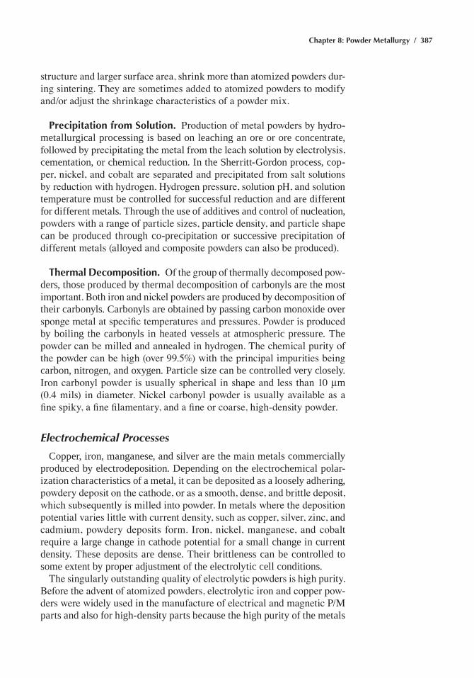
Chapter 8: Powder Metallurgy / 387
structure and larger surface area, shrink more than atomized powders dur-ing sintering. They are sometimes added to atomized powders to modify and/or adjust the shrinkage characteristics of a powder mix.
Precipitation from Solution. Production of metal powders by hydro-metallurgical processing is based on leaching an ore or ore concentrate, followed by precipitating the metal from the leach solution by electrolysis, cementation, or chemical reduction. In the Sherritt-Gordon process, cop-per, nickel, and cobalt are separated and precipitated from salt solutions by reduction with hydrogen. Hydrogen pressure, solution pH, and solution temperature must be controlled for successful reduction and are different for different metals. Through the use of additives and control of nucleation, powders with a range of particle sizes, particle density, and particle shape can be produced through co-precipitation or successive precipitation of different metals (alloyed and composite powders can also be produced).
Thermal Decomposition. Of the group of thermally decomposed pow-ders, those produced by thermal decomposition of carbonyls are the most important. Both iron and nickel powders are produced by decomposition of their carbonyls. Carbonyls are obtained by passing carbon monoxide over sponge metal at specific temperatures and pressures. Powder is produced by boiling the carbonyls in heated vessels at atmospheric pressure. The powder can be milled and annealed in hydrogen. The chemical purity of the powder can be high (over 99.5%) with the principal impurities being carbon, nitrogen, and oxygen. Particle size can be controlled very closely. Iron carbonyl powder is usually spherical in shape and less than 10 mm (0.4 mils) in diameter. Nickel carbonyl powder is usually available as a fine spiky, a fine filamentary, and a fine or coarse, high-density powder.
Electrochemical Processes
Copper, iron, manganese, and silver are the main metals commercially produced by electrodeposition. Depending on the electrochemical polar-ization characteristics of a metal, it can be deposited as a loosely adhering, powdery deposit on the cathode, or as a smooth, dense, and brittle deposit, which subsequently is milled into powder. In metals where the deposition potential varies little with current density, such as copper, silver, zinc, and cadmium, powdery deposits form. Iron, nickel, manganese, and cobalt require a large change in cathode potential for a small change in current density. These deposits are dense. Their brittleness can be controlled to some extent by proper adjustment of the electrolytic cell conditions.
The singularly outstanding quality of electrolytic powders is high purity. Before the advent of atomized powders, electrolytic iron and copper pow-ders were widely used in the manufacture of electrical and magnetic P/M parts and also for high-density parts because the high purity of the metals
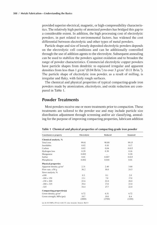
388 / Metals Fabrication—Understanding the Basics
provided superior electrical, magnetic, or high-compressibility characteris-tics. The relatively high purity of atomized powders has bridged this gap to a considerable extent. In addition, the high processing cost of electrolytic powders, in part related to environmental factors, has widened the cost differential between electrolytic and other types of metal powders.
Particle shape and size of loosely deposited electrolytic powders depends on the electrolytic cell conditions and can be additionally controlled through the use of addition agents to the electrolyte. Subsequent annealing can be used to stabilize the powders against oxidation and to broaden the range of powder characteristics. Commercial electrolytic copper powders have particle shapes from dendritic to equiaxed irregular and apparent densities from less than 1 g/cm3 (0.04 lb/in.3) to over 3 g/cm3 (0.11 lb/in.3). The particle shape of electrolytic iron powder, as a result of milling, is irregular and flaky, with fairly rough surfaces.
The chemical and physical properties of typical compacting-grade iron powders made by atomization, electrolysis, and oxide reduction are com-pared in Table 1.
Powder Treatments
Most powders receive one or more treatments prior to compaction. These treatments are tailored to the powder use and may include particle size distribution adjustment through screening and/or air classifying, anneal-ing for the purpose of improving compacting properties, lubricant addition
Table 1 Chemical and physical properties of compacting-grade iron powder
Constituent or property Electrolytic Reduced Atomized
Chemical analysis, %Total iron 99.61 98.80 99.15Insolubles 0.02 0.10 0.17Carbon 0.02 0.04 0.015Hydrogen loss 0.29 0.30 0.16Manganese 0.002 … 0.20Sulfur 0.01 0.007 0.015Phosphorus 0.002 0.010 0.01
Physical propertiesApparent density, g/cm3 2.31 2.40 3.00Flow rate, s/50 g 38.2 30.0 24.5Sieve analysis, %+100 0.5 0.1 2.0–100 + 150 13.1 7.0 17.0–150 + 200 22.6 22.0 28.0–200 + 325 29.4 17.0 22.0–325 34.4 27.7 22.0
Compacting properties(a)Green density, g/cm3 6.72 6.51 6.72Green strength, MPa (psi) 19.7
(2800)19.0
(2700)8.4
(1200)
(a) At 414 MPa (30 tsi) with 1% zinc stearate. Source: Ref 4
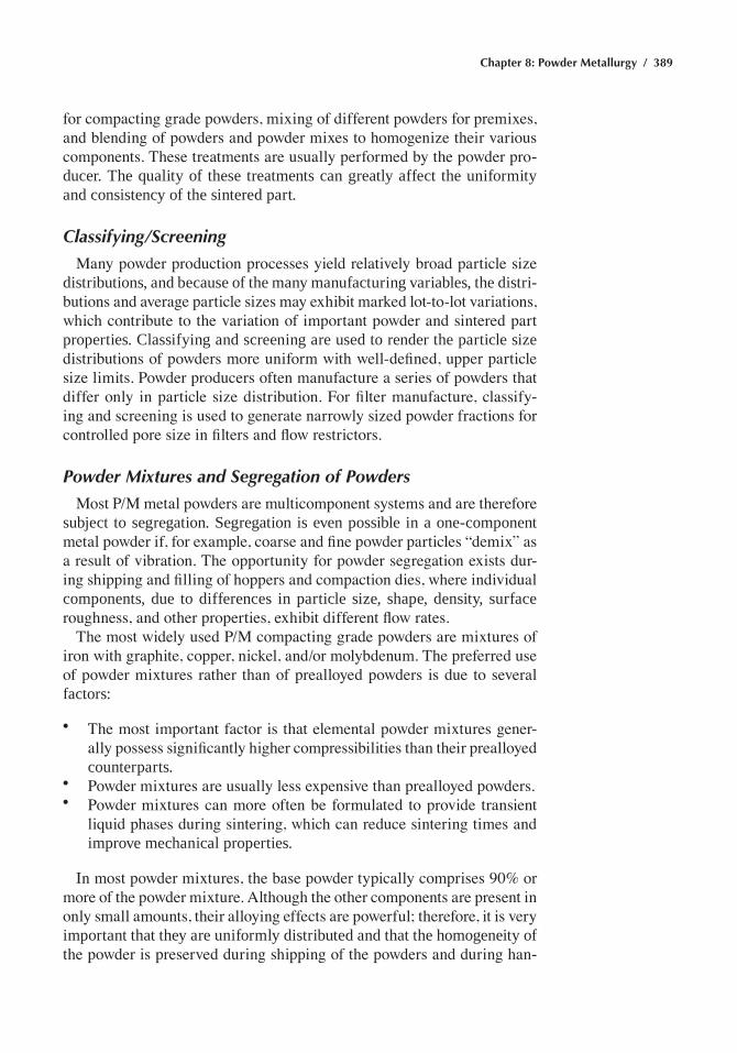
Chapter 8: Powder Metallurgy / 389
for compacting grade powders, mixing of different powders for premixes, and blending of powders and powder mixes to homogenize their various components. These treatments are usually performed by the powder pro-ducer. The quality of these treatments can greatly affect the uniformity and consistency of the sintered part.
Classifying/Screening
Many powder production processes yield relatively broad particle size distributions, and because of the many manufacturing variables, the distri-butions and average particle sizes may exhibit marked lot-to-lot variations, which contribute to the variation of important powder and sintered part properties. Classifying and screening are used to render the particle size distributions of powders more uniform with well-defined, upper particle size limits. Powder producers often manufacture a series of powders that differ only in particle size distribution. For filter manufacture, classify-ing and screening is used to generate narrowly sized powder fractions for controlled pore size in filters and flow restrictors.
Powder Mixtures and Segregation of Powders
Most P/M metal powders are multicomponent systems and are therefore subject to segregation. Segregation is even possible in a one-component metal powder if, for example, coarse and fine powder particles “demix” as a result of vibration. The opportunity for powder segregation exists dur-ing shipping and filling of hoppers and compaction dies, where individual components, due to differences in particle size, shape, density, surface roughness, and other properties, exhibit different flow rates.
The most widely used P/M compacting grade powders are mixtures of iron with graphite, copper, nickel, and/or molybdenum. The preferred use of powder mixtures rather than of prealloyed powders is due to several factors:
• The most important factor is that elemental powder mixtures gener-ally possess significantly higher compressibilities than their prealloyed counterparts.
• Powder mixtures are usually less expensive than prealloyed powders.• Powder mixtures can more often be formulated to provide transient
liquid phases during sintering, which can reduce sintering times and improve mechanical properties.
In most powder mixtures, the base powder typically comprises 90% or more of the powder mixture. Although the other components are present in only small amounts, their alloying effects are powerful; therefore, it is very important that they are uniformly distributed and that the homogeneity of the powder is preserved during shipping of the powders and during han-
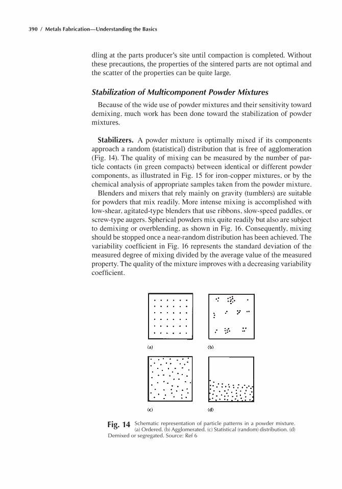
390 / Metals Fabrication—Understanding the Basics
dling at the parts producer’s site until compaction is completed. Without these precautions, the properties of the sintered parts are not optimal and the scatter of the properties can be quite large.
Stabilization of Multicomponent Powder Mixtures
Because of the wide use of powder mixtures and their sensitivity toward demixing, much work has been done toward the stabilization of powder mixtures.
Stabilizers. A powder mixture is optimally mixed if its components approach a random (statistical) distribution that is free of agglomeration (Fig. 14). The quality of mixing can be measured by the number of par-ticle contacts (in green compacts) between identical or different powder components, as illustrated in Fig. 15 for iron-copper mixtures, or by the chemical analysis of appropriate samples taken from the powder mixture.
Blenders and mixers that rely mainly on gravity (tumblers) are suitable for powders that mix readily. More intense mixing is accomplished with low-shear, agitated-type blenders that use ribbons, slow-speed paddles, or screw-type augers. Spherical powders mix quite readily but also are subject to demixing or overblending, as shown in Fig. 16. Consequently, mixing should be stopped once a near-random distribution has been achieved. The variability coefficient in Fig. 16 represents the standard deviation of the measured degree of mixing divided by the average value of the measured property. The quality of the mixture improves with a decreasing variability coefficient.
Fig. 14 Schematic representation of particle patterns in a powder mixture. (a) Ordered. (b) agglomerated. (c) Statistical (random) distribution. (d)
Demixed or segregated. Source: ref 6
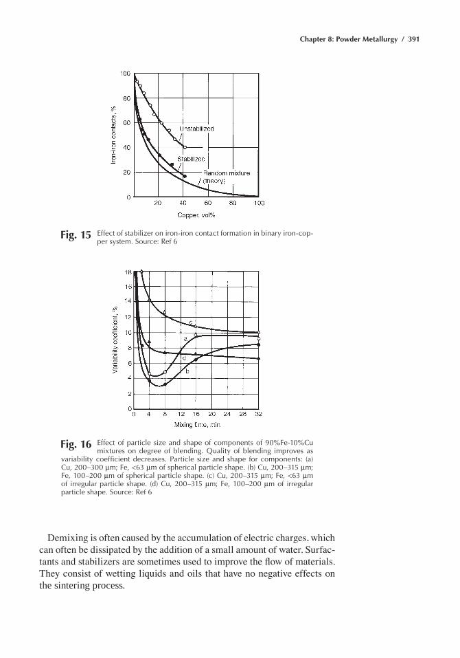
Chapter 8: Powder Metallurgy / 391
Demixing is often caused by the accumulation of electric charges, which can often be dissipated by the addition of a small amount of water. Surfac-tants and stabilizers are sometimes used to improve the flow of materials. They consist of wetting liquids and oils that have no negative effects on the sintering process.
Fig. 15 effect of stabilizer on iron-iron contact formation in binary iron-cop-per system. Source: ref 6
Fig. 16 effect of particle size and shape of components of 90%Fe-10%Cu mixtures on degree of blending. Quality of blending improves as
variability coefficient decreases. particle size and shape for components: (a) Cu, 200–300 mm; Fe, <63 mm of spherical particle shape. (b) Cu, 200–315 mm; Fe, 100–200 mm of spherical particle shape. (c) Cu, 200–315 mm; Fe, <63 mm of irregular particle shape. (d) Cu, 200–315 mm; Fe, 100–200 mm of irregular particle shape. Source: ref 6
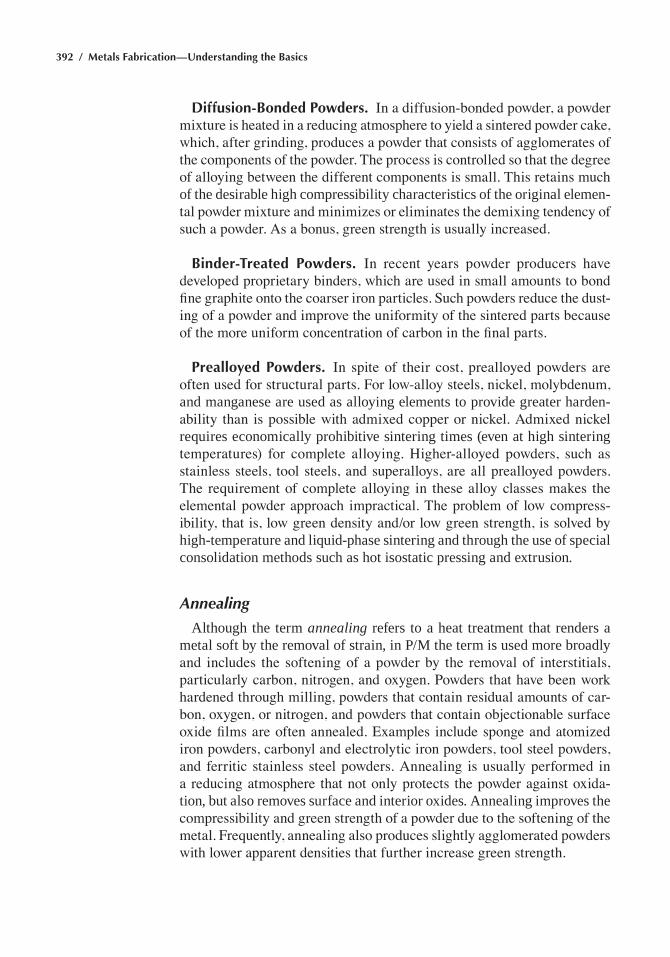
392 / Metals Fabrication—Understanding the Basics
Diffusion-Bonded Powders. In a diffusion-bonded powder, a powder mixture is heated in a reducing atmosphere to yield a sintered powder cake, which, after grinding, produces a powder that consists of agglomerates of the components of the powder. The process is controlled so that the degree of alloying between the different components is small. This retains much of the desirable high compressibility characteristics of the original elemen-tal powder mixture and minimizes or eliminates the demixing tendency of such a powder. As a bonus, green strength is usually increased.
Binder-Treated Powders. In recent years powder producers have developed proprietary binders, which are used in small amounts to bond fine graphite onto the coarser iron particles. Such powders reduce the dust-ing of a powder and improve the uniformity of the sintered parts because of the more uniform concentration of carbon in the final parts.
Prealloyed Powders. In spite of their cost, prealloyed powders are often used for structural parts. For low-alloy steels, nickel, molybdenum, and manganese are used as alloying elements to provide greater harden-ability than is possible with admixed copper or nickel. Admixed nickel requires economically prohibitive sintering times (even at high sintering temperatures) for complete alloying. Higher-alloyed powders, such as stainless steels, tool steels, and superalloys, are all prealloyed powders. The requirement of complete alloying in these alloy classes makes the elemental powder approach impractical. The problem of low compress-ibility, that is, low green density and/or low green strength, is solved by high-temperature and liquid-phase sintering and through the use of special consolidation methods such as hot isostatic pressing and extrusion.
Annealing
Although the term annealing refers to a heat treatment that renders a metal soft by the removal of strain, in P/M the term is used more broadly and includes the softening of a powder by the removal of interstitials, particularly carbon, nitrogen, and oxygen. Powders that have been work hardened through milling, powders that contain residual amounts of car-bon, oxygen, or nitrogen, and powders that contain objectionable surface oxide films are often annealed. Examples include sponge and atomized iron powders, carbonyl and electrolytic iron powders, tool steel powders, and ferritic stainless steel powders. Annealing is usually performed in a reducing atmosphere that not only protects the powder against oxida-tion, but also removes surface and interior oxides. Annealing improves the compressibility and green strength of a powder due to the softening of the metal. Frequently, annealing also produces slightly agglomerated powders with lower apparent densities that further increase green strength.
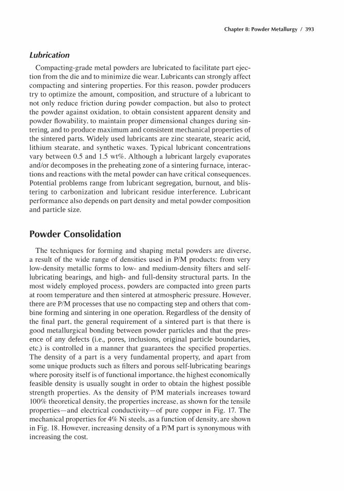
Chapter 8: Powder Metallurgy / 393
Lubrication
Compacting-grade metal powders are lubricated to facilitate part ejec-tion from the die and to minimize die wear. Lubricants can strongly affect compacting and sintering properties. For this reason, powder producers try to optimize the amount, composition, and structure of a lubricant to not only reduce friction during powder compaction, but also to protect the powder against oxidation, to obtain consistent apparent density and powder flowability, to maintain proper dimensional changes during sin-tering, and to produce maximum and consistent mechanical properties of the sintered parts. Widely used lubricants are zinc stearate, stearic acid, lithium stearate, and synthetic waxes. Typical lubricant concentrations vary between 0.5 and 1.5 wt%. Although a lubricant largely evaporates and/or decomposes in the preheating zone of a sintering furnace, interac-tions and reactions with the metal powder can have critical consequences. Potential problems range from lubricant segregation, burnout, and blis-tering to carbonization and lubricant residue interference. Lubricant performance also depends on part density and metal powder composition and particle size.
Powder Consolidation
The techniques for forming and shaping metal powders are diverse, a result of the wide range of densities used in P/M products: from very low-density metallic forms to low- and medium-density filters and self-lubricating bearings, and high- and full-density structural parts. In the most widely employed process, powders are compacted into green parts at room temperature and then sintered at atmospheric pressure. However, there are P/M processes that use no compacting step and others that com-bine forming and sintering in one operation. Regardless of the density of the final part, the general requirement of a sintered part is that there is good metallurgical bonding between powder particles and that the pres-ence of any defects (i.e., pores, inclusions, original particle boundaries, etc.) is controlled in a manner that guarantees the specified properties. The density of a part is a very fundamental property, and apart from some unique products such as filters and porous self-lubricating bearings where porosity itself is of functional importance, the highest economically feasible density is usually sought in order to obtain the highest possible strength properties. As the density of P/M materials increases toward 100% theoretical density, the properties increase, as shown for the tensile properties—and electrical conductivity—of pure copper in Fig. 17. The mechanical properties for 4% Ni steels, as a function of density, are shown in Fig. 18. However, increasing density of a P/M part is synonymous with increasing the cost.
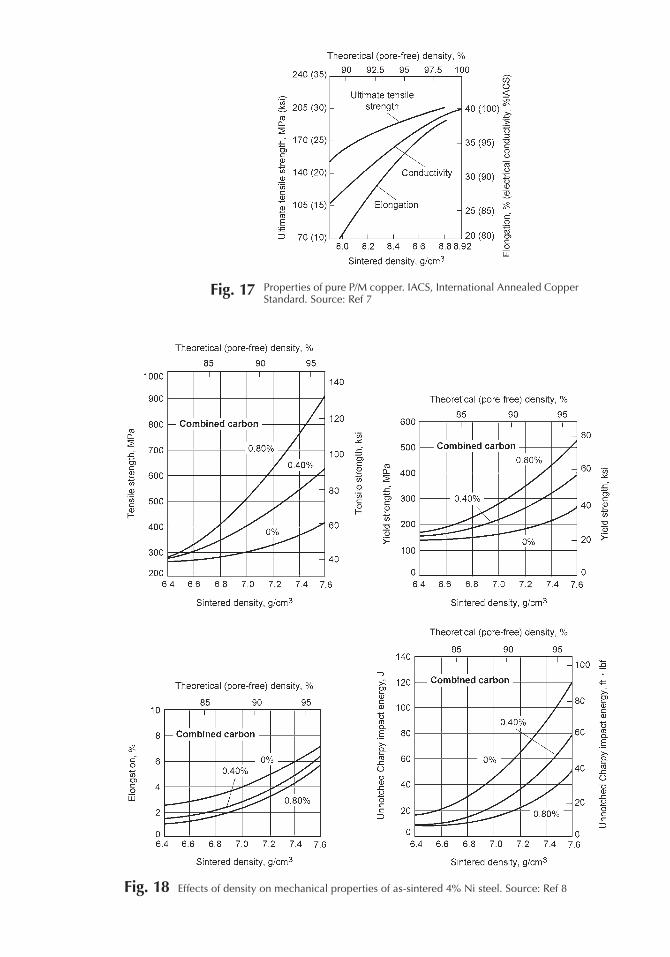
Fig. 17 properties of pure p/M copper. IaCS, International annealed Copper Standard. Source: ref 7
Fig. 18 effects of density on mechanical properties of as-sintered 4% Ni steel. Source: ref 8
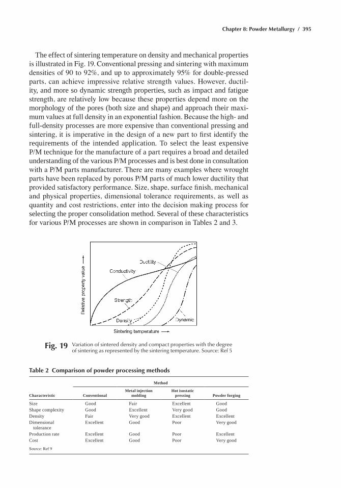
Chapter 8: Powder Metallurgy / 395
The effect of sintering temperature on density and mechanical properties is illustrated in Fig. 19. Conventional pressing and sintering with maximum densities of 90 to 92%, and up to approximately 95% for double-pressed parts, can achieve impressive relative strength values. However, ductil-ity, and more so dynamic strength properties, such as impact and fatigue strength, are relatively low because these properties depend more on the morphology of the pores (both size and shape) and approach their maxi-mum values at full density in an exponential fashion. Because the high- and full-density processes are more expensive than conventional pressing and sintering, it is imperative in the design of a new part to first identify the requirements of the intended application. To select the least expensive P/M technique for the manufacture of a part requires a broad and detailed understanding of the various P/M processes and is best done in consultation with a P/M parts manufacturer. There are many examples where wrought parts have been replaced by porous P/M parts of much lower ductility that provided satisfactory performance. Size, shape, surface finish, mechanical and physical properties, dimensional tolerance requirements, as well as quantity and cost restrictions, enter into the decision making process for selecting the proper consolidation method. Several of these characteristics for various P/M processes are shown in comparison in Tables 2 and 3.
Fig. 19 Variation of sintered density and compact properties with the degree of sintering as represented by the sintering temperature. Source: ref 5
Table 2 Comparison of powder processing methods
Method
Characteristic ConventionalMetal injection
moldingHot isostatic
pressing Powder forging
Size Good Fair Excellent GoodShape complexity Good Excellent Very good GoodDensity Fair Very good Excellent ExcellentDimensional
toleranceExcellent Good Poor Very good
Production rate Excellent Good Poor ExcellentCost Excellent Good Poor Very good
Source: Ref 9
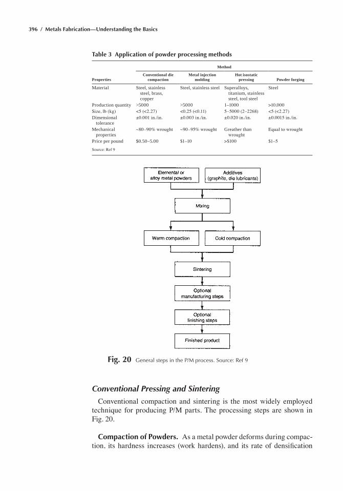
396 / Metals Fabrication—Understanding the Basics
Conventional Pressing and Sintering
Conventional compaction and sintering is the most widely employed technique for producing P/M parts. The processing steps are shown in Fig. 20.
Compaction of Powders. As a metal powder deforms during compac-tion, its hardness increases (work hardens), and its rate of densification
Table 3 Application of powder processing methods
Method
PropertiesConventional die
compactionMetal injection
moldingHot isostatic
pressing Powder forging
Material Steel, stainless steel, brass, copper
Steel, stainless steel Superalloys, titanium, stainless steel, tool steel
Steel
Production quantity >5000 >5000 1–1000 >10,000Size, lb (kg) <5 (<2.27) <0.25 (<0.11) 5–5000 (2–2268) <5 (<2.27)Dimensional
tolerance±0.001 in./in. ±0.003 in./in. ±0.020 in./in. ±0.0015 in./in.
Mechanical properties
~80–90% wrought ~90–95% wrought Greather than wrought
Equal to wrought
Price per pound $0.50–5.00 $1–10 >$100 $1–5
Source: Ref 9
Fig. 20 General steps in the p/M process. Source: ref 9
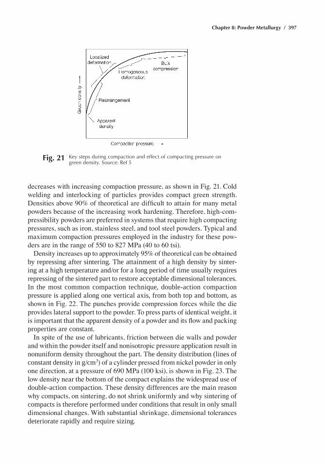
Chapter 8: Powder Metallurgy / 397
decreases with increasing compaction pressure, as shown in Fig. 21. Cold welding and interlocking of particles provides compact green strength. Densities above 90% of theoretical are difficult to attain for many metal powders because of the increasing work hardening. Therefore, high-com-pressibility powders are preferred in systems that require high compacting pressures, such as iron, stainless steel, and tool steel powders. Typical and maximum compaction pressures employed in the industry for these pow-ders are in the range of 550 to 827 MPa (40 to 60 tsi).
Density increases up to approximately 95% of theoretical can be obtained by repressing after sintering. The attainment of a high density by sinter-ing at a high temperature and/or for a long period of time usually requires repressing of the sintered part to restore acceptable dimensional tolerances. In the most common compaction technique, double-action compaction pressure is applied along one vertical axis, from both top and bottom, as shown in Fig. 22. The punches provide compression forces while the die provides lateral support to the powder. To press parts of identical weight, it is important that the apparent density of a powder and its flow and packing properties are constant.
In spite of the use of lubricants, friction between die walls and powder and within the powder itself and nonisotropic pressure application result in nonuniform density throughout the part. The density distribution (lines of constant density in g/cm3) of a cylinder pressed from nickel powder in only one direction, at a pressure of 690 MPa (100 ksi), is shown in Fig. 23. The low density near the bottom of the compact explains the widespread use of double-action compaction. These density differences are the main reason why compacts, on sintering, do not shrink uniformly and why sintering of compacts is therefore performed under conditions that result in only small dimensional changes. With substantial shrinkage, dimensional tolerances deteriorate rapidly and require sizing.
Fig. 21 Key steps during compaction and effect of compacting pressure on green density. Source: ref 5
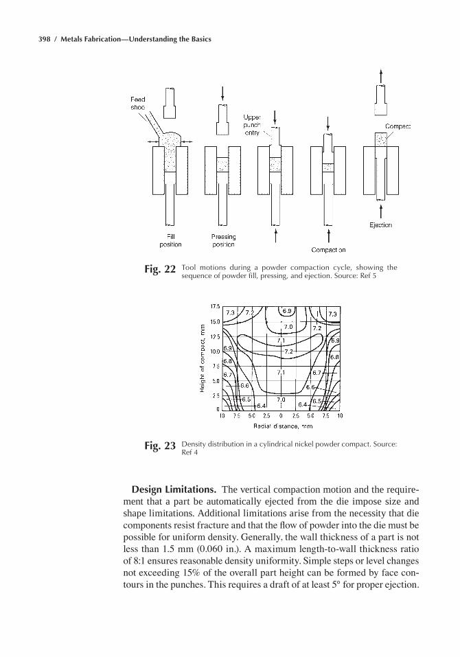
398 / Metals Fabrication—Understanding the Basics
Fig. 22 tool motions during a powder compaction cycle, showing the sequence of powder fill, pressing, and ejection. Source: ref 5
Fig. 23 Density distribution in a cylindrical nickel powder compact. Source: ref 4
Design Limitations. The vertical compaction motion and the require-ment that a part be automatically ejected from the die impose size and shape limitations. Additional limitations arise from the necessity that die components resist fracture and that the flow of powder into the die must be possible for uniform density. Generally, the wall thickness of a part is not less than 1.5 mm (0.060 in.). A maximum length-to-wall thickness ratio of 8:1 ensures reasonable density uniformity. Simple steps or level changes not exceeding 15% of the overall part height can be formed by face con-tours in the punches. This requires a draft of at least 5° for proper ejection.
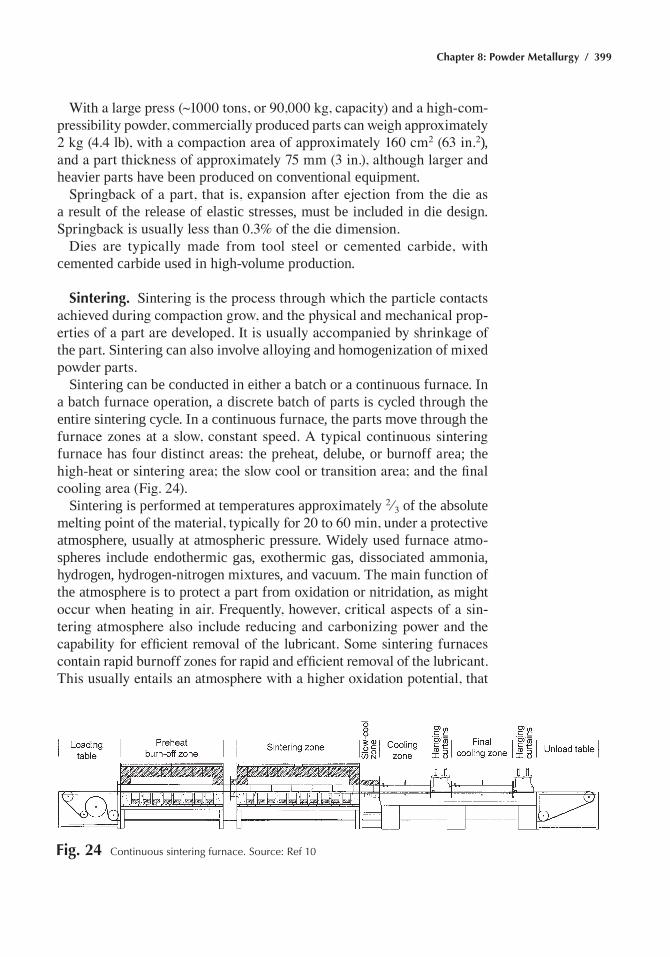
Chapter 8: Powder Metallurgy / 399
With a large press (~1000 tons, or 90,000 kg, capacity) and a high-com-pressibility powder, commercially produced parts can weigh approximately 2 kg (4.4 lb), with a compaction area of approximately 160 cm2 (63 in.2), and a part thickness of approximately 75 mm (3 in.), although larger and heavier parts have been produced on conventional equipment.
Springback of a part, that is, expansion after ejection from the die as a result of the release of elastic stresses, must be included in die design. Springback is usually less than 0.3% of the die dimension.
Dies are typically made from tool steel or cemented carbide, with cemented carbide used in high-volume production.
Sintering. Sintering is the process through which the particle contacts achieved during compaction grow, and the physical and mechanical prop-erties of a part are developed. It is usually accompanied by shrinkage of the part. Sintering can also involve alloying and homogenization of mixed powder parts.
Sintering can be conducted in either a batch or a continuous furnace. In a batch furnace operation, a discrete batch of parts is cycled through the entire sintering cycle. In a continuous furnace, the parts move through the furnace zones at a slow, constant speed. A typical continuous sintering furnace has four distinct areas: the preheat, delube, or burnoff area; the high-heat or sintering area; the slow cool or transition area; and the final cooling area (Fig. 24).
Sintering is performed at temperatures approximately 2⁄3 of the absolute melting point of the material, typically for 20 to 60 min, under a protective atmosphere, usually at atmospheric pressure. Widely used furnace atmo-spheres include endothermic gas, exothermic gas, dissociated ammonia, hydrogen, hydrogen-nitrogen mixtures, and vacuum. The main function of the atmosphere is to protect a part from oxidation or nitridation, as might occur when heating in air. Frequently, however, critical aspects of a sin-tering atmosphere also include reducing and carbonizing power and the capability for efficient removal of the lubricant. Some sintering furnaces contain rapid burnoff zones for rapid and efficient removal of the lubricant. This usually entails an atmosphere with a higher oxidation potential, that
Fig. 24 Continuous sintering furnace. Source: ref 10
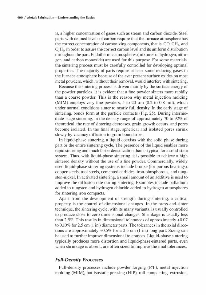
400 / Metals Fabrication—Understanding the Basics
is, a higher concentration of gases such as steam and carbon dioxide. Steel parts with defined levels of carbon require that the furnace atmosphere has the correct concentration of carbonizing components, that is, CO, CH4, and C3H8, in order to assure the correct carbon level and its uniform distribution throughout the part. Endothermic atmospheres (mixtures of hydrogen, nitro-gen, and carbon monoxide) are used for this purpose. For some materials, the sintering process must be carefully controlled for developing optimal properties. The majority of parts require at least some reducing gases in the furnace atmosphere because of the ever present surface oxides on most metal powders, which, without their removal, would interfere with sintering.
Because the sintering process is driven mainly by the surface energy of the powder particles, it is evident that a fine powder sinters more rapidly than a coarse powder. This is the reason why metal injection molding (MIM) employs very fine powders, 5 to 20 mm (0.2 to 0.8 mil), which under normal conditions sinter to nearly full density. In the early stage of sintering, bonds form at the particle contacts (Fig. 25). During interme-diate-stage sintering, in the density range of approximately 70 to 92% of theoretical, the rate of sintering decreases, grain growth occurs, and pores become isolated. In the final stage, spherical and isolated pores shrink slowly by vacancy diffusion to grain boundaries.
In liquid-phase sintering, a liquid coexists with the solid phase during part or the entire sintering cycle. The presence of the liquid enables more rapid sintering and much faster densification than is typical for a solid-state system. Thus, with liquid-phase sintering, it is possible to achieve a high sintered density without the use of a fine powder. Commercially, widely used liquid-phase sintering systems include bronze (for porous bearings), copper steels, tool steels, cemented carbides, iron-phosphorous, and tung-sten-nickel. In activated sintering, a small amount of an additive is used to improve the diffusion rate during sintering. Examples include palladium added to tungsten and hydrogen chloride added to hydrogen atmospheres for sintering iron compacts.
Apart from the development of strength during sintering, a critical property is the control of dimensional changes. In the press-and-sinter technique, the sintering cycle, with its many variants, is usually controlled to produce close to zero dimensional changes. Shrinkage is usually less than 2.5%. This results in dimensional tolerances of approximately +0.07 to 0.10% for 2.5 cm (1 in.) diameter parts. The tolerances in the axial direc-tions are approximately +0.5% for a 2.5 cm (1 in.) long part. Sizing can be used to further improve dimensional tolerances. Liquid-phase sintering typically produces more distortion and liquid-phase-sintered parts, even when shrinkage is absent, are often sized to improve the final tolerances.
Full-Density Processes
Full-density processes include powder forging (P/F), metal injection molding (MIM), hot isostatic pressing (HIP), roll compacting, extrusion,
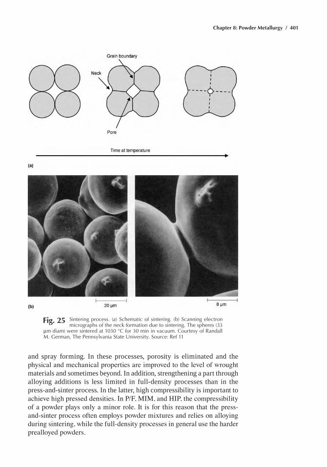
Chapter 8: Powder Metallurgy / 401
Fig. 25 Sintering process. (a) Schematic of sintering. (b) Scanning electron micrographs of the neck formation due to sintering. the spheres (33
mm diam) were sintered at 1030 °C for 30 min in vacuum. Courtesy of randall M. German, the pennsylvania State University. Source: ref 11
and spray forming. In these processes, porosity is eliminated and the physical and mechanical properties are improved to the level of wrought materials and sometimes beyond. In addition, strengthening a part through alloying additions is less limited in full-density processes than in the press-and-sinter process. In the latter, high compressibility is important to achieve high pressed densities. In P/F, MIM, and HIP, the compressibility of a powder plays only a minor role. It is for this reason that the press-and-sinter process often employs powder mixtures and relies on alloying during sintering, while the full-density processes in general use the harder prealloyed powders.
402 / Metals Fabrication—Understanding the Basics
Compared to conventional wrought materials, several of the full-density processes offer complex shape capabilities and advantages in material uti-lization, energy efficiency, and precision. However, these advantages are obtained through the use of more expensive processing. High or full den-sity alone is not sufficient to achieve superior properties. Most full-density processes use “clean” powders, and any nonreducible surface oxides are limited to very small amounts and, if present, are broken up and homoge-neously distributed through shear deformation. Fully dense P/M materials can exceed the properties of wrought materials of the same composition through control of the microstructure, that is, control of various defects, homogeneity of structure, and the smaller grain size.
Powder Forging. In powder forging (P/F), a preform shape is cold pressed to between 75 and 85% of full density, sintered, heated to the forg-ing temperature, and then forged in closed dies using one blow to produce a fully dense net or near-net shape. Although the sintering step is optional, it is normally included as a particle surface cleaning step (deoxidation) and to improve the workability of the porous preform. There are two classes of forging practice. In repressing, the preform shape is nearly identical to the forged shape. In true forging (upsetting), considerable shear deforma-tion is involved because the preform is a different shape than the forging.
In hot repressing, material flow is mainly in the direction of pressing, while in hot upsetting, the preform undergoes a significant amount of lat-eral material flow. Hot upsetting, with its large amount of shear stresses, is effective in breaking up powder particle oxide films, which improves the metallurgical bond between particle interfaces and improves fatigue properties. Toughness and fatigue resistance are higher for forged parts than for repressed parts.
Normally, powder forging is performed hot (1000 to 1200 °C, or 1800 to 2200 °F, for steel powders), but it can also be conducted at warm or at room temperature (cold forging). Typical steel powder forging pressures are 550 to 950 MPa (40 to 70 tsi). Because the workability of a porous pre-form is poor, the design of the preform is critical in avoiding defects. Local surface tensile stresses and internal hydrostatic tension must be avoided. With a correct preform shape and a well-controlled process, powder forged parts have sound microstructures, good hardenability, and performance that meets or exceeds wrought part performance. Although P/F involves less handling, fewer dies and processing steps, and produces less scrap than conventional forging of cast materials, it is primarily used for the high-volume production of automotive parts. This is attributed to the high cost for developing preforms and maintaining forging dies and automated production systems.
Metal Injection Molding. The MIM process combines the structural benefits of metallic materials with the shape complexity of plastic injec-
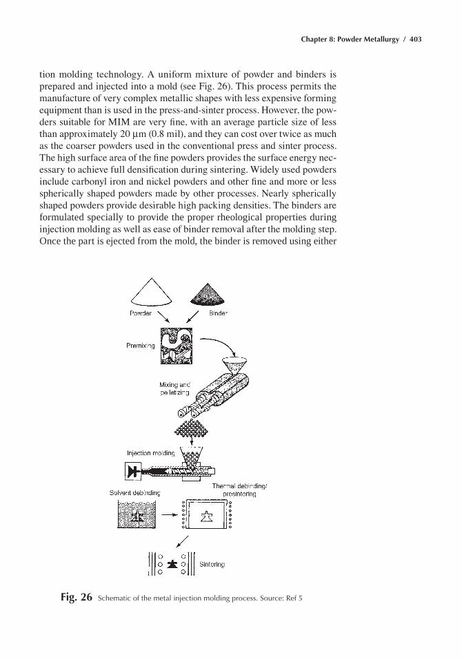
Chapter 8: Powder Metallurgy / 403
tion molding technology. A uniform mixture of powder and binders is prepared and injected into a mold (see Fig. 26). This process permits the manufacture of very complex metallic shapes with less expensive forming equipment than is used in the press-and-sinter process. However, the pow-ders suitable for MIM are very fine, with an average particle size of less than approximately 20 mm (0.8 mil), and they can cost over twice as much as the coarser powders used in the conventional press and sinter process. The high surface area of the fine powders provides the surface energy nec-essary to achieve full densification during sintering. Widely used powders include carbonyl iron and nickel powders and other fine and more or less spherically shaped powders made by other processes. Nearly spherically shaped powders provide desirable high packing densities. The binders are formulated specially to provide the proper rheological properties during injection molding as well as ease of binder removal after the molding step. Once the part is ejected from the mold, the binder is removed using either
Fig. 26 Schematic of the metal injection molding process. Source: ref 5
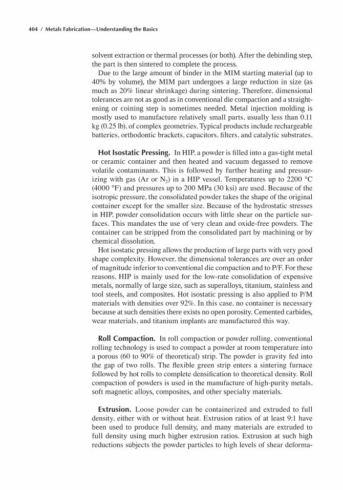
404 / Metals Fabrication—Understanding the Basics
solvent extraction or thermal processes (or both). After the debinding step, the part is then sintered to complete the process.
Due to the large amount of binder in the MIM starting material (up to 40% by volume), the MIM part undergoes a large reduction in size (as much as 20% linear shrinkage) during sintering. Therefore, dimensional tolerances are not as good as in conventional die compaction and a straight-ening or coining step is sometimes needed. Metal injection molding is mostly used to manufacture relatively small parts, usually less than 0.11 kg (0.25 lb), of complex geometries. Typical products include rechargeable batteries, orthodontic brackets, capacitors, filters, and catalytic substrates.
Hot Isostatic Pressing. In HIP, a powder is filled into a gas-tight metal or ceramic container and then heated and vacuum degassed to remove volatile contaminants. This is followed by further heating and pressur-izing with gas (Ar or N2) in a HIP vessel. Temperatures up to 2200 °C (4000 °F) and pressures up to 200 MPa (30 ksi) are used. Because of the isotropic pressure, the consolidated powder takes the shape of the original container except for the smaller size. Because of the hydrostatic stresses in HIP, powder consolidation occurs with little shear on the particle sur-faces. This mandates the use of very clean and oxide-free powders. The container can be stripped from the consolidated part by machining or by chemical dissolution.
Hot isostatic pressing allows the production of large parts with very good shape complexity. However, the dimensional tolerances are over an order of magnitude inferior to conventional die compaction and to P/F. For these reasons, HIP is mainly used for the low-rate consolidation of expensive metals, normally of large size, such as superalloys, titanium, stainless and tool steels, and composites. Hot isostatic pressing is also applied to P/M materials with densities over 92%. In this case, no container is necessary because at such densities there exists no open porosity. Cemented carbides, wear materials, and titanium implants are manufactured this way.
Roll Compaction. In roll compaction or powder rolling, conventional rolling technology is used to compact a powder at room temperature into a porous (60 to 90% of theoretical) strip. The powder is gravity fed into the gap of two rolls. The flexible green strip enters a sintering furnace followed by hot rolls to complete densification to theoretical density. Roll compaction of powders is used in the manufacture of high-purity metals, soft magnetic alloys, composites, and other specialty materials.
Extrusion. Loose powder can be containerized and extruded to full density, either with or without heat. Extrusion ratios of at least 9:1 have been used to produce full density, and many materials are extruded to full density using much higher extrusion ratios. Extrusion at such high reductions subjects the powder particles to high levels of shear deforma-
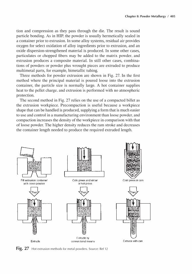
Chapter 8: Powder Metallurgy / 405
tion and compression as they pass through the die. The result is sound particle bonding. As in HIP, the powder is usually hermetically sealed in a container prior to extrusion. In some alloy systems, residual air provides oxygen for select oxidation of alloy ingredients prior to extrusion, and an oxide dispersion-strengthened material is produced. In some other cases, particulates or chopped fibers may be added to the matrix powder, and extrusion produces a composite material. In still other cases, combina-tions of powders or powder plus wrought pieces are extruded to produce multimetal parts, for example, bimetallic tubing.
Three methods for powder extrusion are shown in Fig. 27. In the first method where the principal material is poured loose into the extrusion container, the particle size is normally large. A hot container supplies heat to the pellet charge, and extrusion is performed with no atmospheric protection.
The second method in Fig. 27 relies on the use of a compacted billet as the extrusion workpiece. Precompaction is useful because a workpiece shape that can be handled is produced, supplying a form that is much easier to use and control in a manufacturing environment than loose powder, and compaction increases the density of the workpiece in comparison with that of loose powder. The higher density reduces the ram stroke and decreases the container length needed to produce the required extruded length.
Fig. 27 hot extrusion methods for metal powders. Source: ref 12
406 / Metals Fabrication—Understanding the Basics
A more elaborate method to powder billet preparation is that shown in the third variation in Fig. 27, where powder is first partially densified directly in a can. The can may then be evacuated and sealed, or it may be left open to the atmosphere. When high purity must be maintained, can-ning the powder, including evacuation and sealing, is an essential step. Billet preparation for critical applications, such as gas turbine engine com-ponents, requires that filling and evacuation be performed with great care. Procedures may include clean-room container preparation and assembly, total isolation of powder from ambient air, evacuation at slightly elevated temperatures to drive off adsorbed gases from particle surfaces, and leak checking of sealed containers. The extruded product must be free from both prior particle boundary contaminants and nonmetallic inclusions that degrade mechanical properties, especially fracture toughness and fatigue resistance.
Spray Forming. In spray forming, inert gas-atomized powder is directed onto a substrate. With proper process control, the atomized droplets reach the substrate surface in semisolid condition and splat deform to full or nearly full density. Rapid heat extraction results in minimal segregation in even complex alloys and in very good homogeneity. Deposition rates of up to 2 kg/s (5.5 lb/s) are possible. Spray forming is currently being used for nickel, copper, and aluminum alloys.
Powder Metallurgy Part Defects
The problem of forming defects in green parts during compaction and ejection has become more prevalent as parts producers have begun to use higher compaction pressures in an effort to achieve high-density, high-performance P/M parts. The four most common types of defects in P/M parts are ejection cracks, density variations, microlaminations, and poor sintering.
Ejection Cracks. When a part has been pressed, there are large residual stresses in the part due to the constraint of the die and punches, which are relieved as the part is ejected from the die. The strains associated with this stress relief depend on the compacting pressure, the green expansion of the material being compacted, and the rigidity of the die. Green expan-sion, also known as spring out, is the difference between the ejected part size and the die size. A typical value of green expansion for a powder mix based on atomized iron powder pressed at relatively high pressure (600 to 700 MPa, or 45 to 50 tsi) is 0.20%. For example, in a partially ejected compact, the portion that is out of the die expands to relieve the residual stresses, while the constrained portion remains die size and a shear stress is imposed on the compact. When the ability of the powder compact to
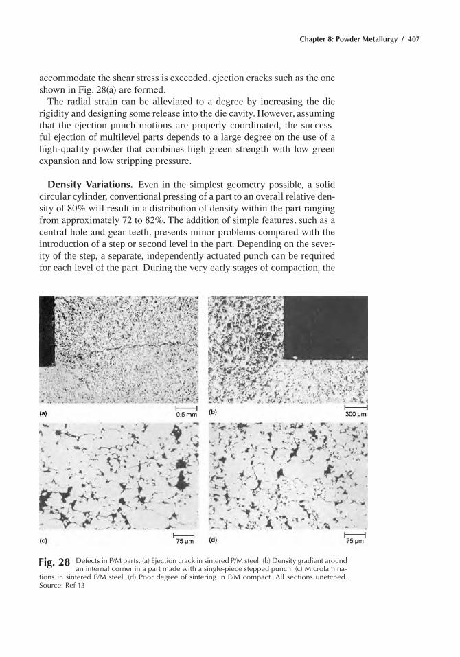
Chapter 8: Powder Metallurgy / 407
accommodate the shear stress is exceeded, ejection cracks such as the one shown in Fig. 28(a) are formed.
The radial strain can be alleviated to a degree by increasing the die rigidity and designing some release into the die cavity. However, assuming that the ejection punch motions are properly coordinated, the success-ful ejection of multilevel parts depends to a large degree on the use of a high-quality powder that combines high green strength with low green expansion and low stripping pressure.
Density Variations. Even in the simplest geometry possible, a solid circular cylinder, conventional pressing of a part to an overall relative den-sity of 80% will result in a distribution of density within the part ranging from approximately 72 to 82%. The addition of simple features, such as a central hole and gear teeth, presents minor problems compared with the introduction of a step or second level in the part. Depending on the sever-ity of the step, a separate, independently actuated punch can be required for each level of the part. During the very early stages of compaction, the
Fig. 28 Defects in p/M parts. (a) ejection crack in sintered p/M steel. (b) Density gradient around an internal corner in a part made with a single-piece stepped punch. (c) Microlamina-
tions in sintered p/M steel. (d) poor degree of sintering in p/M compact. all sections unetched. Source: ref 13
408 / Metals Fabrication—Understanding the Basics
powder redistributes itself by flowing between sections of the die cav-ity. However, when the pressure increases and the powder movement is restricted, shearing of the compact in planes parallel to the punch axis can only be avoided by proper coordination of punch motions. When such shear exists, a density gradient results. The density gradient is not always severe enough for an associated crack to form upon ejection. However, a low-density area around an internal corner, as shown in Fig. 28(b), can be a fatal flaw, because this corner is usually a point of stress concentration when the part is loaded in service.
Microlaminations. In micrographs of unetched part cross sections, microlaminations such as those shown in Fig. 28(c) appear as layers of unsintered interparticle boundaries that are oriented in planes normal to the punch axis. They can be the result of fine microcracks associated with shear stresses upon ejection; such microcracks fail to heal during sinter-ing. Because of their orientation parallel to the tensile axis of standard test bars, they have little influence on the measured tensile properties of the bars, but are presumed to be a cause of severe anisotropy of tensile properties.
Poor Sintering. When unsintered particle boundaries result from a cause other than shear stresses, they are usually present because of insuf-ficient sintering time or sintering temperature, a nonreducing atmosphere, poor lubricant burnoff, inhibition of graphite dissolution, or a combination of these. A severe example is shown in Fig. 28(d). Unlike microlamina-tions, defects associated with a poor degree of sintering are not oriented in planes.
Secondary Operations
Sometimes sintered parts require special treatments, known as second-ary and/or finishing operations, to meet final application requirements. These include heat treatments, joining, repressing and sizing, machining, and various kinds of surface treatments. The presence of residual porosity requires special precautions in some of these processes.
Heat treatments are used to increase the surface hardness for improved wear resistance or to increase the hardness of the entire part to increase strength. Powder metallurgy parts with residual porosity are heat treated in carburizing and nitriding gases or in noncorrosive liquids (quench oils). Porosity in P/M parts increases the depth of carburization, there-fore, parts to be case carburized should have a density of at least 7.2 g/cm3 (0.26 lb/in.3) to avoid penetration of the carbonizing gas into the part interior. Lower-density parts are sometimes copper infiltrated to meet that requirement.
Chapter 8: Powder Metallurgy / 409
The hardenability of P/M parts is reduced due to the presence of pores, which reduces thermal conductivity and the cooling rate. Although manga-nese and chromium significantly improve hardenability, their use is limited to very low dew point atmospheres, which prevents oxidation of these elements.
Porous steel parts can be steam treated to improve wear and corrosion resistance and to provide low-pressure leak tightness. The treatment is performed at low temperature in superheated steam. The steam oxidizes the surface pores, which close through formation of an adherent layer of bluish to black iron oxide (Fe3O4).
Joining. At low porosity levels (<8%), P/M parts can be joined similar to wrought materials. At densities of 80 to 90%, joining techniques based on fusion (welding and brazing) are successful provided the amount of melt is kept low. For lower densities, special brazing alloys have been developed, which minimizes the amount of filler metal penetrating the pore space of a part. Copper infiltration can be used to sinter, infiltrate, and braze an assembly of several green parts in a single operation.
Repressing and Sizing. Pressed and sintered parts can be repressed to increase their density and mechanical properties, or just sized to reduce their dimensional variations.
Machining. Powder metallurgy can be machined to add features not possible with uniaxial pressing, that is, threads, undercuts, and horizon-tal holes, or to improve dimensions and surface roughness. The presence of pores reduces the heat conductivity of a part leading to heat erosion. Pores also cause a mild form of interrupted cutting, which imposes cyclic stresses on the tool, thereby reducing its fatigue life. Copper infiltration and resin impregnation are successfully used for improving the machin-ability of porous P/M parts. Powder metallurgy parts requiring machining are often pressed with machinability enhancing additives, such as MnS, MoS2, lead, tellurium, and tin.
Surface Treatments. Examples of surface treatments used for P/M parts include deburring, plating, polishing, sealing, and shot peening.
Dry or wet tumbling or vibrating P/M parts, with or without an abrasive medium, removes their surface flashes and burrs that were formed in the pressing operation. Cleaning or washing is often combined with deburring to remove surface contaminants.
Powder metallurgy parts with densities above 83% can be mechanically plated in a tumbling barrel using glass beads, water, and the metal plating powder. Parts with densities above approximately 94% can be electro-plated. In lower-density parts the pores are closed by impregnation or, if applicable, through burnishing, buffing, or steam treating.
410 / Metals Fabrication—Understanding the Basics
Shot peening is used to improve the fatigue life of P/M parts. The repeated impacts of small-diameter shot generate cold worked surfaces with compressive residual stresses.
ACKNOWLEDGMENT
This chapter was adapted from Powder Metallurgy in Metals Handbook Desk Edition, 2nd ed., ASM International, 1998.
REFERENCES
1. P/M Parts Showcase, Met. Powder Rep., Vol 50 (No. 1), p 5 2. P.K. Johnson, Winning Parts Show High Strength and Cost Savings,
Int. J. Powder Metall., Vol 22 (No. 4), 1986, p 267–272 3. E. Klar and P.K. Samal, Powder Metallurgy Stainless Steels, Powder
Metal Technologies and Applications, Vol 7, ASM Handbook, ASM International, 1998
4. Powder Metallurgy, Vol 7, Metals Handbook, 9th ed., American Society for Metals, 1984
5. R.M. German, Powder Metallurgy Science, 2nd ed., Metal Powder Industries Federation, 1994
6. Pulvermetallurgie Sinter und Verbundwerkstoffe, W. Schatt, Ed., VEB Deutscher Verlag fur Grundstoffindustrie, Leipzig, 1979
7. F.V. Lenel, Powder Metallurgy—Principles and Applications, Metal Powder Industries Federation, 1980, p 426
8. L.F. Pease III and V.C. Potter, Mechanical Properties of P/M Mate-rials, Powder Metallurgy, Vol 7, ASM Handbook (formerly Metals Handbook, 9th ed.), American Society for Metals, 1984, p 467
9. H.I. Sanderow, Design for Powder Metallurgy, in Materials Selection and Design, Vol 20, ASM Handbook, 1997, p 745–753
10. Sintering Furnaces and Atmospheres, Powder Metal Technologies and Applications, Vol 7, ASM Handbook, ASM International, 1998
11. Powder Metallurgy, Metals Handbook Desk Edition, 2nd ed., ASM International, 1998
12. B.L. Ferguson and P.R. Roberts, Extrusion of Metal Powders, Powder Metal Technologies and Applications, Vol 7, ASM Handbook, ASM International, 1998
13. R.C. O’Brien and W.B. James, Nondestructive Inspection of Powder Metallurgy Parts, Nondestructive Evaluation and Quality Control, Vol 17, ASM Handbook, ASM International, 1992
SELECTED REFERENCES• H.V. Atkinson and B.A. Rickinson, Hot Isostatic Pressing, Adam Hil-
ger, 1991

Chapter 8: Powder Metallurgy / 411
• G. Dowson, Powder Metallurgy: The Process and its Products, Adam Hilger, 1990
• R.M. German, Powder Metallurgy Science, 2nd ed., Metal Powder Industries Federation, 1995
• H.A. Kuhn and B.L. Ferguson, Powder Forging, Metal Powder Indus-tries Federation, 1990
• L.F. Pease III and W.G. West, Fundamentals of Powder Metallurgy, Metal Powder Industries Federation, 2002
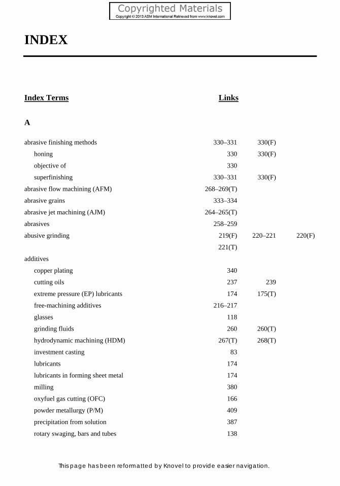
This page has been reformatted by Knovel to provide easier navigation.
INDEX
Index Terms Links
A
abrasive finishing methods 330–331 330(F)
honing 330 330(F)
objective of 330
superfinishing 330–331 330(F)
abrasive flow machining (AFM) 268–269(T)
abrasive grains 333–334
abrasive jet machining (AJM) 264–265(T)
abrasives 258–259
abusive grinding 219(F) 220–221 220(F)
221(T)
additives
copper plating 340
cutting oils 237 239
extreme pressure (EP) lubricants 174 175(T)
free-machining additives 216–217
glasses 118
grinding fluids 260 260(T)
hydrodynamic machining (HDM) 267(T) 268(T)
investment casting 83
lubricants 174
lubricants in forming sheet metal 174
milling 380
oxyfuel gas cutting (OFC) 166
powder metallurgy (P/M) 409
precipitation from solution 387
rotary swaging, bars and tubes 138
Index Terms Links
This page has been reformatted by Knovel to provide easier navigation.
aerospace applications
aircraft industry 13
chromate conversion coatings 339
electroless nickel plating 344
lubricants 361
manual spinning 198
powder metallurgy products 373
power spinning 198
ring rolling 138
stretch forming 196
thermal evaporation 361
vacuum arc remelting (VAR) 13
vacuum induction melting (VIM) 11
aging
aging curves for Al-4% Cu alloy 318(F)
artificial aging 317 322–323 322(F)
323(F)
natural aging 317 320–322 321(F)
precipitation hardening, aluminum alloys 317 320–323 321(F)
322(F) 323(F)
agitation
martempering 293
quenching 285
air melting 8
air plasma spraying (APS) 351 352
AKDQ steel. See aluminum-killed drawing-
quality (AKDQ) steel
alligatoring 31 31(F)
alloy steel refining 8–16(F) 17(F)
electroslag remelting (ESR) 12 14–16(F)
overview 8–9(F)
vacuum arc remelting (VAR) 12–14(F)
vacuum induction melting (VIM) 9–12(F)
Index Terms Links
This page has been reformatted by Knovel to provide easier navigation.
alloying elements
aluminum 38
argon oxygen decarburization (AOD) 18
basic oxygen furnace (BOF) 5–6
casting alloys 49
corrosion-resistance stainless steels 329
depth of hardening 286
die steels 116
effect of 286 288
electric arc furnace (EAF) 7
forming operations 169
hardenability 286 288
high-speed tool steels 230
hot working 106
machinability, workpiece 216
martensitic steels 281
nitriding 311
nitriding steels 311
prealloyed powders 392
precipitation hardening 314
precipitation hardening, aluminum alloys 317
quenching 283
risering 62
rotary swaging, bars and tubes 140
temper embrittlement 297
tempering 290
time-temperature-transformation (TTT) diagram 279 280 280(F)
vacuum arc remelting (VAR) 13
vacuum induction melting (VIM) 11 12
aluminum
capped steels 20
as deoxidizing agent 19
precipitation-hardening heat treatment 315(F)
Index Terms Links
This page has been reformatted by Knovel to provide easier navigation.
aluminum alloys
flow stress 207(T)
forging imperfections 121
rolling mills 28
superplastic forming/diffusion bonding (SPF/DB) 209
aluminum bronzes 171(T) 172
aluminum nitride (AlN) particles 37 170 311
aluminum production 37–42(F)
alloying elements 38
Bayer process 37
electrolytic cell 38(F)
Hall-Héroult process 37 38(F)
inoculants 38
overview 37–40(F)
oxides and gasses, controlling 38
process 37–40(F)
recycling 37
rolling plate and sheet (see aluminum
production, plate and sheet)
semicontinuous direct-chill process 38–40 39(F)
aluminum production, plate and sheet 40–42(F)
cold rolling 42
grain directionality due to rolling 41(F)
homogenizing 40
hot rolling 40–41(F)
intermediate annealing 41–42
preheating 40
scalping, of ingots 40
steps for 40
aluminum-killed drawing-quality (AKDQ) steel 35
annealing
aluminum plate and sheet 41–42
aluminum-killed drawing-quality (AKDQ) steel 35
batch annealing, steels 35 35(F) 36(F)
Index Terms Links
This page has been reformatted by Knovel to provide easier navigation.
annealing (Cont.)
continuous annealing, steels 23(F) 35–37 35(F)
36(F)
drawing 159
hypoeutectoid steels 276–277
interstitial-free (IF) steel 35
normalizing 277 298
overview 276–277
powder treatments 392
process annealing and stress relief 277
recrystallization 277
steels 276 276(F)
(see also steels, cold rolling and annealing)
subcritically annealed cold rolled steels 35(F) 36–37
anti-chills 88–89
antimony 7 297 348
Antioch process 81
APS. See air plasma spraying (APS)
aqueous corrosion 18 325 366(T)
argon oxygen decarburization (AOD)
alloys, used in refining 18
argon oxygen decarburization vessel 17(F)
stainless steel refining 16–18
vacuum induction melting (VIM) of superalloys 12
arsenic 7 297 348
artificial aging 317
ASEA Quintus rubber-pad process 199
ASTM International austenite grain size 58 281(F) 286
atomization 381–385
centrifugal atomization 381
compacting-grade iron powders 388 388(T)
dual atomization 384
microstructures of T15 tool steel 385(F)
oxides, water atomization 384–385
Index Terms Links
This page has been reformatted by Knovel to provide easier navigation.
atomization (Cont.)
particle shape 382–384 383(F) 388
particle size 388
particle size distributions 384 384(F)
quenching 382 383
schematic of atomization processes 383(F)
ultrasonic atomization 383
vacuum, or soluble-gas, atomization 382
water atomization setup 383(F) 384
austempering 293–295
advantages 293–294
applications 295
carbon content 294–295
cycle 294
objective of 293
process 293 294(F)
selection of steel for 294–295
time-temperature-transformation (TTT) diagram 294
austenitizing 276(F) 281–282
automotive industry
electromagnetic forming (EMF) 206
evaporative pattern casting 81–82 82(F)
hot dip coatings 348
powder metallurgy 373–374 374(F)
roll forging 134
B
babbitting 348–349
bainite
austempering 293 294 295
hot rolling, steels 34
interrupted quenching 292
iron-carbon system 275 275(F)
martempering 292
Index Terms Links
This page has been reformatted by Knovel to provide easier navigation.
bainite (Cont.)
surface hardening 298
tempering 291
time-temperature-transformation (TTT) diagram 280 281 282(F)
ball bearing steels 13
basic oxygen furnace (BOF) 4–6
alloying elements 5–6
degassing 6
ironmaking 4
ladle furnace 6
tapping 5–6
baths
martempering 293
plating baths 345–346
Bayer process 37
bct. See body-centered tetragonal (bct)
bendability 184 186
bending 180 180(F)
Bessemer process 4
billets
defined 23
long products 33
rolling mills 33
biscuit 93
bismuth 12 216
blankholder 190 202
blanking 176–178(F)
blanking 176
blanking die, relief in 176(F)
blanks 176
coining 148
cutoff 177 177(F)
notching 177
overview 176
Index Terms Links
This page has been reformatted by Knovel to provide easier navigation.
blanking (Cont.)
parting 177 178(F)
piercing 177
relief 176
relief angle 176 176(F)
terminology 176
trimming 177
vertical wear land 176 176(F)
blanks 176
manual spinning 197
rubber-pad forming 200
blast furnace
ironmaking 1–4 2(F) 3(F)
refractory lining bricks 4
blisters 31
blooms
defined 23
long products 33
rolling mills 33
blowholes 19 29
body-centered cubic (bcc) structure 169 272 274
275 283
body-centered tetragonal (bct) 275 283 289
BOF. See basic oxygen furnace (BOF)
bombardment 363
bosh 4
buffing
abrasive grains 333–334
color buffing 333–334
hard buffing 333
overview 331 333
powder metallurgy parts 409
built-up edge 225 225(F)
Index Terms Links
This page has been reformatted by Knovel to provide easier navigation.
bulk deformation
closed-die forging 124–130(F)
cold extrusion 151–153(F) 154(F)
cold forging 148–151(F)
cold working 107–109(T)
die design and materials 113–116(F)
die steels 116–117
drawing 157–160(F)
forging 109 110(F)
forging, friction and lubrication in 117–118
forging imperfections 119–122(F)
forging processes 122–130(F)
hammers 110–111(F) 112(T)
high-energy-rate forging 134–137(F)
hot extrusion 154–157(F,T)
hot upset forging 130–132(F)
hot working 104–107(F)
hot-die forging 144–146(F)
isothermal forging 144–146(F)
open-die forging 122–124(F)
overview 103 104(F)
precision forging 146–147 148(F)
presses 110–111 111(F) 112–113
processes 104(F)
radial forging 140–141(F)
ring rolling 137–138(F)
roll forging 132–134(F)
rotary forging 141–144(F)
rotary swaging, bars and tubes 138–140(F)
use of term 103
burning 319
burnishing 409
bursts 121
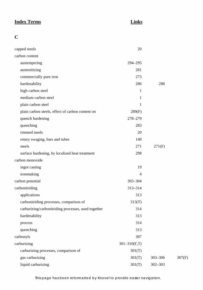
Index Terms Links
This page has been reformatted by Knovel to provide easier navigation.
C
capped steels 20
carbon content
austempering 294–295
austenitizing 281
commercially pure iron 273
hardenability 286 288
high carbon steel 1
medium carbon steel 1
plain carbon steel 1
plain carbon steels, effect of carbon content on 289(F)
quench hardening 278–279
quenching 283
rimmed steels 20
rotary swaging, bars and tubes 140
steels 271 271(F)
surface hardening, by localized heat treatment 298
carbon monoxide
ingot casting 19
ironmaking 4
carbon potential 303–304
carbonitriding 313–314
applications 313
carbonitriding processes, comparison of 313(T)
carburizing/carbonitriding processes, used together 314
hardenability 313
process 314
quenching 313
carbonyls 387
carburizing 301–310(F,T)
carburizing processes, comparison of 301(T)
gas carburizing 301(T) 303–306 307(F)
liquid carburizing 301(T) 302–303
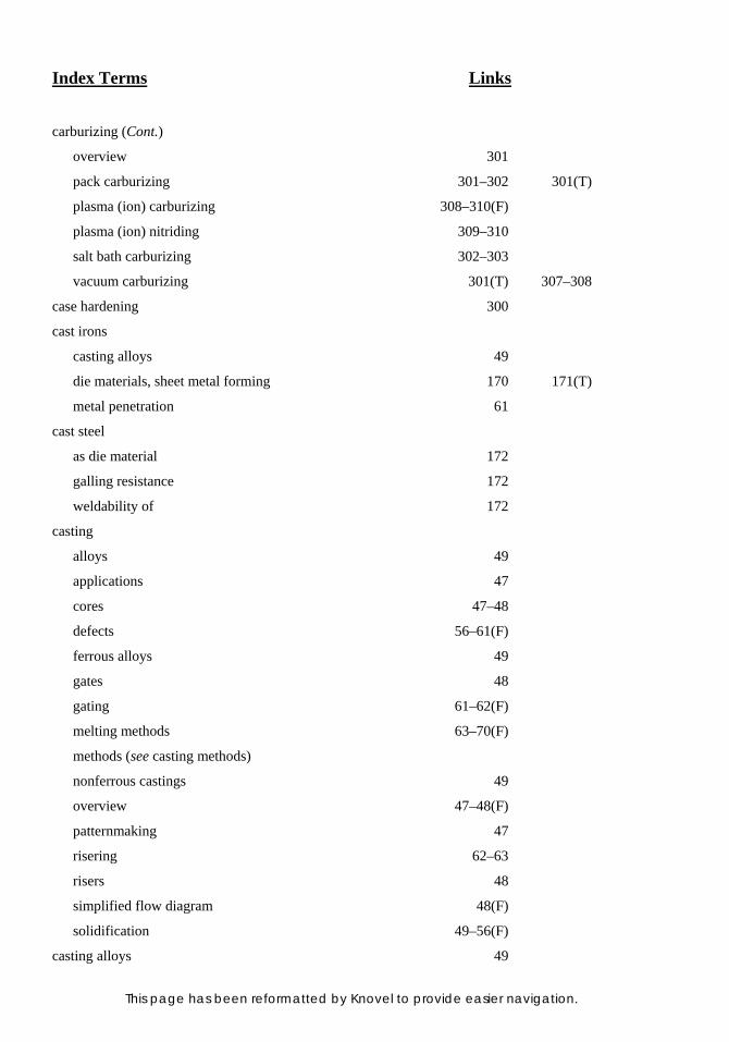
Index Terms Links
This page has been reformatted by Knovel to provide easier navigation.
carburizing (Cont.)
overview 301
pack carburizing 301–302 301(T)
plasma (ion) carburizing 308–310(F)
plasma (ion) nitriding 309–310
salt bath carburizing 302–303
vacuum carburizing 301(T) 307–308
case hardening 300
cast irons
casting alloys 49
die materials, sheet metal forming 170 171(T)
metal penetration 61
cast steel
as die material 172
galling resistance 172
weldability of 172
casting
alloys 49
applications 47
cores 47–48
defects 56–61(F)
ferrous alloys 49
gates 48
gating 61–62(F)
melting methods 63–70(F)
methods (see casting methods)
nonferrous castings 49
overview 47–48(F)
patternmaking 47
risering 62–63
risers 48
simplified flow diagram 48(F)
solidification 49–56(F)
casting alloys 49
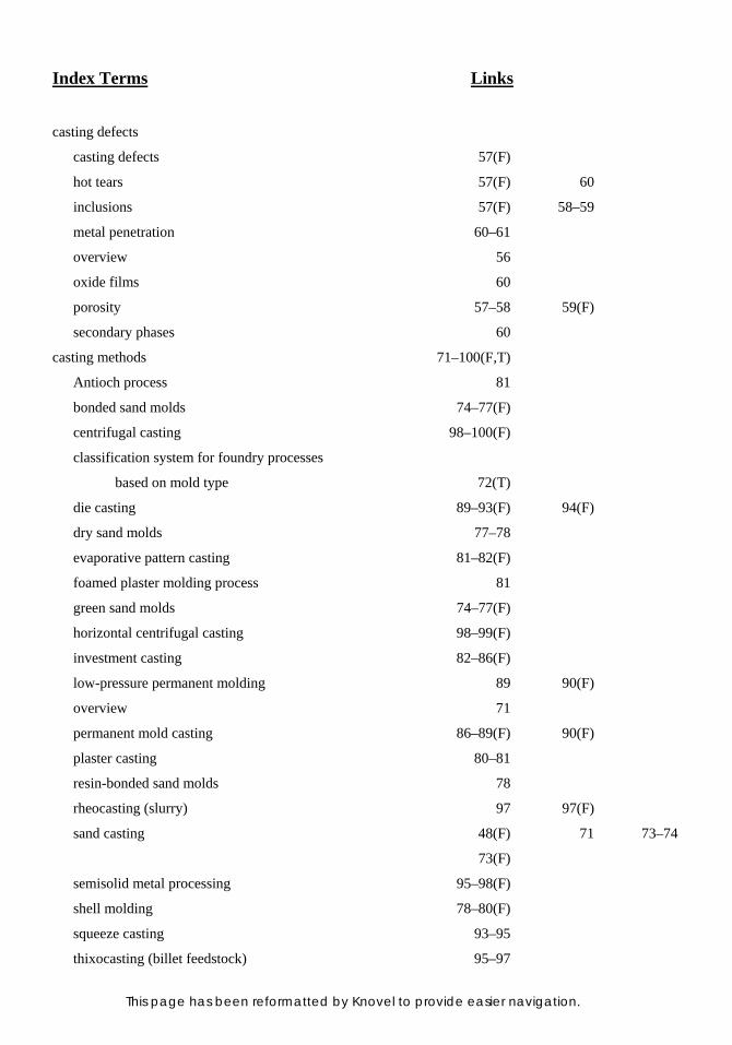
Index Terms Links
This page has been reformatted by Knovel to provide easier navigation.
casting defects
casting defects 57(F)
hot tears 57(F) 60
inclusions 57(F) 58–59
metal penetration 60–61
overview 56
oxide films 60
porosity 57–58 59(F)
secondary phases 60
casting methods 71–100(F,T)
Antioch process 81
bonded sand molds 74–77(F)
centrifugal casting 98–100(F)
classification system for foundry processes
based on mold type 72(T)
die casting 89–93(F) 94(F)
dry sand molds 77–78
evaporative pattern casting 81–82(F)
foamed plaster molding process 81
green sand molds 74–77(F)
horizontal centrifugal casting 98–99(F)
investment casting 82–86(F)
low-pressure permanent molding 89 90(F)
overview 71
permanent mold casting 86–89(F) 90(F)
plaster casting 80–81
resin-bonded sand molds 78
rheocasting (slurry) 97 97(F)
sand casting 48(F) 71 73–74
73(F)
semisolid metal processing 95–98(F)
shell molding 78–80(F)
squeeze casting 93–95
thixocasting (billet feedstock) 95–97
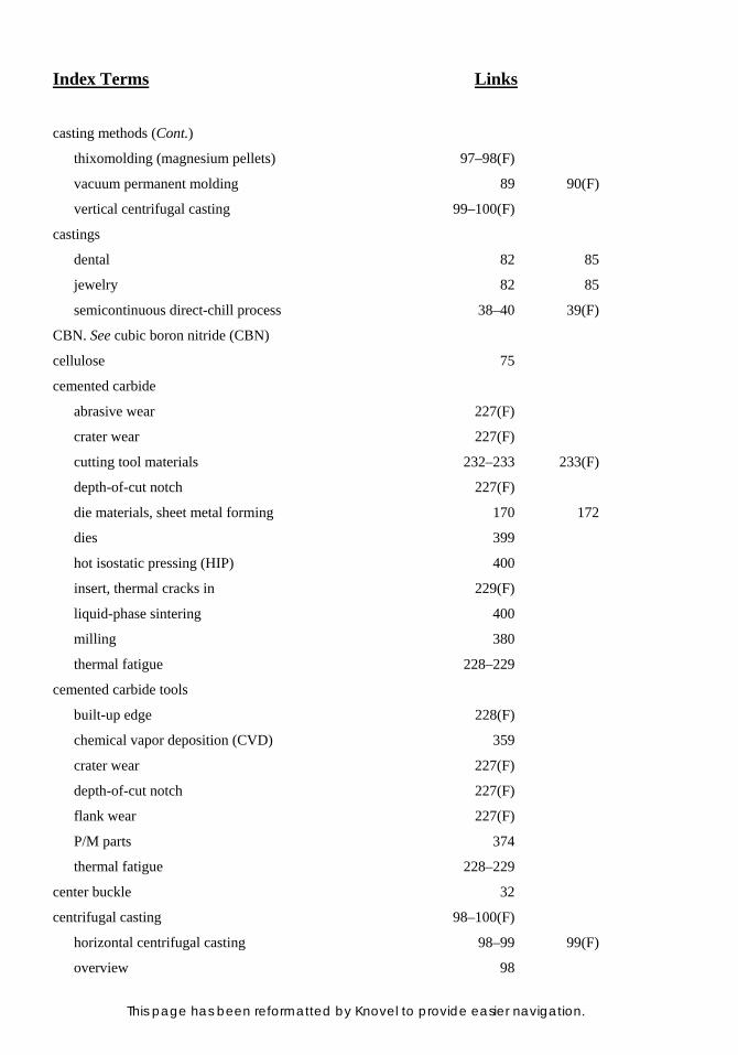
Index Terms Links
This page has been reformatted by Knovel to provide easier navigation.
casting methods (Cont.)
thixomolding (magnesium pellets) 97–98(F)
vacuum permanent molding 89 90(F)
vertical centrifugal casting 99–100(F)
castings
dental 82 85
jewelry 82 85
semicontinuous direct-chill process 38–40 39(F)
CBN. See cubic boron nitride (CBN)
cellulose 75
cemented carbide
abrasive wear 227(F)
crater wear 227(F)
cutting tool materials 232–233 233(F)
depth-of-cut notch 227(F)
die materials, sheet metal forming 170 172
dies 399
hot isostatic pressing (HIP) 400
insert, thermal cracks in 229(F)
liquid-phase sintering 400
milling 380
thermal fatigue 228–229
cemented carbide tools
built-up edge 228(F)
chemical vapor deposition (CVD) 359
crater wear 227(F)
depth-of-cut notch 227(F)
flank wear 227(F)
P/M parts 374
thermal fatigue 228–229
center buckle 32
centrifugal casting 98–100(F)
horizontal centrifugal casting 98–99 99(F)
overview 98
Index Terms Links
This page has been reformatted by Knovel to provide easier navigation.
centrifugal casting (Cont.)
vertical centrifugal casting 99–100 100(F)
ceramic coatings 353–355
applications 354
carbides 354
cermet coatings 355
overview 353–354
oxides 354
phosphate-bonded coatings 354–355
silicate glasses 354
silicides 354
ceramic slurries 84–85
cerium 31
cermets 233–234
chemical machining (CHM) 264–265(T)
chemical vapor deposition (CVD) 357–360(T)
CVD materials 358–360
ceramics 359 359(T)
diamond films 359–360
metals 358
deposition temperatures for thermal and
plasma chemical vapor deposition 358(T)
overview 357–358
process classification 358
thermal decomposition (pyrolysis) 358 358(T)
chill zone 50 54
chip formation, mechanics of 222–225(F)
basic metal cutting operation 222–223
built-up edge 225 225(F)
chip, workpiece, and tool relationship 223(F)
chip flow 252–253 255(F)
chip formation 223–224 223(F)
chip types 224(F)
chip-breaker grooves 254
Index Terms Links
This page has been reformatted by Knovel to provide easier navigation.
chip formation, mechanics of (Cont.)
chip-control geometries 254
oblique cutting 223 223(F)
orthogonal cutting 223 223(F)
shear zone 223(F) 224
chip producing processes and equipment 241–250(F) 251(F)
band sawing 243–244 243(T)
chip formation processes 242
circular sawing 243(T) 244
cost and performance comparisons of
hacksawing, band sawing, and circular
sawing 243(T)
cutters 247 248(F)
drilling 249–250 251(F)
dual-turret numerically controlled (NC) lathe 241(F)
hacksawing 243(T) 244
lathes 242 246–247 246(F)
machine tools 241–242
machining centers 242–243 242(F)
milling 247–248 248(F) 249(F)
numerically controlled machining center 242(F)
sawing 243
tool cost ratings 243(T)
tool life ratings 243(T)
turning 244–247 245(F) 246(F)
chromate conversion coatings 339
CIP. See cold isostatic pressing (CIP)
clays (United States) 75
cleaning 326–329
abrasive cleaning 327
acid cleaning 327
alkaline cleaning 327
comparative attributes of selected cleaning processes 328(T)
electrolytic cleaning 327
Index Terms Links
This page has been reformatted by Knovel to provide easier navigation.
cleaning (Cont.)
emulsion cleaning 326
metal cleaning processes for removing
selected contaminants 329(T)
molten salt bath cleaning 327–328
overview 326
phosphoric acid etching 327
solvent cleaning 326
substrate considerations 328–329
ultrasonic cleaning 328
vapor degreasing 326
cleanliness. See also cleaning
atomization 380
electroslag remelting (ESR) 16
grinding fluids 260(T)
hot tears 60
physical vapor deposition (PVD) 360
powder cleanliness 379
steelmaking 7–8
vacuum arc remelting (VAR) 12–13
clinker 3
closed-die forging 124–130(F)
applications 124 127
classifications
blocker-type forgings 127
close-tolerance forgings 128
conventional closed-die forgings 127–128
cold forging 124
die impressions 128–129(F)
with flash 125(F)
flow stress 127
forging size 127
hot forging 124
material requirements 127
Index Terms Links
This page has been reformatted by Knovel to provide easier navigation.
closed-die forging (Cont.)
multiple-impression hammer dies 128(F)
process variables
die heating 130
flash 129 129(F)
trimming 130
warm forging 124
without flash 126(F)
CNC. See computer numerical controls (CNC)
CO2 lasers 168 168(F)
coatings. See also finishing and coating
cemented carbides 233
ceramic coatings 353–355
chromate conversion coatings 325 339
conversion coatings 118 160 175(T)
hot dip coating, of steels 346–348(F,T)
mold coatings 61 87 88
99
multicomponent coatings 357
organic coatings 325 365–366 368(T)
thermal barrier coatings (TBCs) 361–362 362(F)
thermal spray coatings 350–353(T)
cobalt-base cutting tools 232
coefficient of thermal expansion 58–59 87 359(T)
coining 148–150(F)
coining dies 149
decorative items 149
die setup 149(F)
materials suitable for 149–150
overview 148
progressive die operations 148
sizing 148
workpiece size 149
Index Terms Links
This page has been reformatted by Knovel to provide easier navigation.
coke
cupola melting 66 68
ironmaking 1–4
seacoal 75
cold drawing 37 157 159
160
cold extrusion 151–153(F) 154(F)
applications 153
displacement of metal in cold extrusion 152(F)
extrusion pressure 153 153(F)
extrusion ratio 151 153
impact extrusion (impacting) 153
process 151
tensile strength, effect on extrudability 153 154(F)
workpieces 151
cold forging. See also coining
definition of 148
overview 148
cold heading 150–151(F)
advantages 150
applications 150
folding effect 150(F)
length of upset per stroke 150–151
materials suitable for 150
overview 150
use of a coning punch in the first blow of a
two-blow heading operation 151(F)
cold isostatic pressing (CIP) 378–379
cold rolling
aluminum production, plate and sheet 42
steels (see steels, cold rolling and annealing)
cold shuts 122
cold working 107–109
advantages 109
Index Terms Links
This page has been reformatted by Knovel to provide easier navigation.
cold working (Cont.)
ductility 108
empirical relationship between flow stress
and plastic strain 107–108 108(T)
lubrication 109
nonmetallic inclusions 108
strength coefficients 108(T)
tension test 108–109
warm working 108 108(T)
work-hardening exponents 108(T)
working temperature, effect of 108
coloring 334 335
columnar zone 51(F) 54 55
55(F)
commercially pure iron 273
compressive strain 186
computer numerical controls (CNC) 199
constitutional supercooling 54
consumable electrodes 12 13(F) 14
14(F) 37 42
electroslag remelting (ESR) 14 15
vacuum arc remelting (VAR) 14
continuous casting 21–22
advantages 22
continuous steel casting 21(F)
tundish 21–22 21(F)
continuous cooling transformation (CCT) diagrams 278–281
4340 steel 282(F)
isothermal transformation diagram for 4340 steel 281(F)
conversion coatings 118 160 175(T)
copper
commercial electrolytic copper powders 388
copper plating 340–341
electroless copper plating 345–346
Index Terms Links
This page has been reformatted by Knovel to provide easier navigation.
copper (Cont.)
liquid steel 8
powder metallurgy 376
properties of pure P/M copper 394(F)
in steel 7
core prints 76
cores
green sand molds 76–77
investment cast turbine blade 84(F)
preformed ceramic cores 83
soluble wax cores 83
corrosion resistance
aqueous corrosion 18 325 326(T)
chemical vapor deposition (CVD) 359
chromate conversion coatings 339
intergranular corrosion resistance 18
multicomponent coatings 357
nitriding 311
organic coatings selected for corrosion
resistance in various environments 368(T)
quenching 319
residual elements 7
selecting materials for cutting tools 359(T)
siliconizing 357
steam treating for 409
stress-corrosion resistance 135
thermal spray coatings 352
Couette viscometer 95
cracking
aluminum production 38 40
austenitizing 282
coating cracking 358 368
die steels 117
grain-boundary cracking 8 107
Index Terms Links
This page has been reformatted by Knovel to provide easier navigation.
cracking (Cont.)
hardenability 286 288
hot rolling 40
hot working 105 107
interrupted quenching 291
investment casting 85
isothermal and hot-die forging 146
martempering 292 293
minimum bend radius 185
necks 183
permanent mold casting 88
quench cracking 286 288
quenching 283 285 286
surface hardening 298
surface hardening, by localized heat treatment 298
surface integrity 220
titanium primary fabrication 44
cracks. See also cracking
ejection cracks 406–407 407(F)
shear cracks 122
cropping 21 30(F)
cubic boron nitride (CBN) 229 230 234–235
259
cutters 247 248(F)
cutting fluids 237–241
application of 241
cutting oils 237 239
drilling 239
extreme pressure (EP) lubricants 239
functions of 237
grinding 239–240
high-speed operations 239
low-speed operations 239
lubrication 239
Index Terms Links
This page has been reformatted by Knovel to provide easier navigation.
cutting fluids (Cont.)
overview 237
selection criteria 240
selection of 238–240
tapping and threading 239
types 237
cutting tool materials 229–235(F)
cemented carbides 232–233 233(F)
ceramic tools 234
cermets 233–234
classes of 229
cobalt-base cutting tools 232
cubic boron nitride (CBN) 229 230 234–235
high-speed tool steels 230 231–232 232(F)
polycrystalline diamond (PCD) 229 230 235
relative machining application ranges of
cutting tool materials 230(F)
selecting coating materials 359(T)
specific cutting tool recommendations 230 231(F)
ultrahard tool materials 234–235 235(F)
CVD. See chemical vapor deposition (CVD)
cyclic processing 278
D
deburring
abrasive flow machining (AFM) 268(T) 269(T)
abrasive jet machining (AJM) 264(T)
electrochemical machining (ECM) 263(T)
electropolishing 335
surface treatments, P/M parts 409
thermochemical machining (TCM) 267(T)
decarburization 16–17 35 304
See also argon oxygen decarburization (AOD)
Index Terms Links
This page has been reformatted by Knovel to provide easier navigation.
deep drawing
aluminum killed steels 21 170
blow forming 208
cemented carbides 172
cold rolling 34
ladle metallurgy 7
nonuniform straining during 193–194
presses 190
process 189–190 189(F)
tools, chromium plated 341
deep-quality special-killed (DQSK) steel 170
defects
in rolling (see rolling, defects in)
in sheet metal parts 181–183(F) 184(F)
degassing 6
See also vacuum degassing
demixing 389 390 390(F)
391 392
dendrite formation 52 53(F)
dendrites 52 53(F) 54
diamond. See also polycrystalline diamond (PCD)
abrasive flow machining (AFM) 268
chemical vapor deposition (CVD) 359
cold drawing 160
color buffing 334
diamond films 359–360
electroless nickel plating 344
grinding wheels 259
hot-dip galvanized steels 347(T)
sputtering 363
superabrasives 259
ultrasonic impact grinding (USIG) 266(T)
die casting 89–93
applications 89
Index Terms Links
This page has been reformatted by Knovel to provide easier navigation.
die casting (Cont.)
characteristics 89
cold chamber die casting machine 91(F)
the die 91 92(F)
die failure 93
entrapment of air 93
heat treatment 93
hot chamber die casting machine 90(F)
machines 89–90 90(F) 91(F)
93
process 89
sequence, of the process 91–92
single-cavity die casting die 92(F)
vacuum die casting 89
vertical squeeze casting process 93 94(F)
die design and materials 113–116
die block, size of 115
draft or taper 115
flash allowance 115–116 115(F)
impressions, locating 116
overview 113 114(F)
parting line 113–114
die materials, sheet metal forming 170–172(F,T)
aluminum bronzes 171(T) 172
cast iron 170 171(T)
cast steel 172
cemented carbide 172
hot rolled mild steel plate 171 171(T)
overview 170 171(T)
plastics 172
tool steels 171(T) 172
zinc alloy 170–171 171(T)
die steels 13 116–117
dies and punches, press brake forming 188–189(F)
Index Terms Links
This page has been reformatted by Knovel to provide easier navigation.
DQSK steel. See deep-quality special-killed (DQSK) steel
drag (sand casting) 71
drawability 191–192(T)
limiting draw ratio 191–192
mechanical properties of low-carbon sheets 191(T)
overview 191
plastic strain ratio 191
Swift cup testing 191
drawing 157–160(F)
annealing 159
area reduction per drawing pass 158
dies 160
drawing stress 158
dry drawing 160
with a fixed plug 157–158 158(F)
floating plug 158 159(F)
flow stress 157 158
heat treatment 159
lubrication 159 160
mandrels 160
with a moving mandrel 158 159(F)
process 157
tube drawing 157(F)
tube drawing (tube sinking) 157 158(F)
wet drawing 160
wire or rod drawing 157 157(F)
working temperature 157
workpiece surface, cleaning 159–160
drawing, fundamentals of 190–194(F,T)
anisotropic behavior 193–194 194(F)
blankholder 190
drawability 191–192(T)
earing 194
ears 194 194(F)
Index Terms Links
This page has been reformatted by Knovel to provide easier navigation.
drawing, fundamentals of (Cont.)
forming limit diagram (FLD) 192–194(F)
limiting draw ratio (LDR) 193 193(F)
overview 190
progression of metal flow in drawing a cup
from a flat blank 190(F)
wrinkling 190
drop hammer forming 203–204(F)
advantages 203–204
air drop hammer 203(F)
limitations 204
overview 203
ductility
austempering 293
chips 224
cold extrusion 153
cold rolling 34
cold working 108 109
conventional pressing and sintering 395
drawing 157
electroless copper plating 346
forging 109
heat treatment 271 272 276
high-energy-rate forging (HERF) 137
hot working 107
inclusions 58
intermediate annealing 42 108
machinability 216
minimum bend radius 184
process annealing 277
quench hardening 278–279
radial forging 140
rotary forging 143
spheroidizing 277–278
Index Terms Links
This page has been reformatted by Knovel to provide easier navigation.
ductility (Cont.)
spinning 196 198
steels 271 272 276
straight-knife shearing 163
superplastic forming (SPF) 206–207
tempering, effect of 276 288–289
tin plating 343
work hardening 169
duplex stainless steels 18
dynamic recrystallization 104 107
E
EAF. See electric arc furnace (EAF)
EAF/AOD process 12
earing 194
ears 194 194(F)
EB/PVD TBCs 361–362
EDM. See electrical discharge machining (EDM)
EDWC. See electrical discharge wire cutting (EDWC)
electric arc furnace (EAF) 6–7
schematic cross section 6(F)
steel scrap 6–7
electrical discharge machining (EDM) 214(T) 263(T) 267(T)
268(T)
electrical discharge wire cutting (EDWC) 214(T) 268–269 268(T)
269(T)
electrochemical machining (ECM) 263(T)
electroless plating processes 344–346
electroless copper plating 345–346
electroless nickel plating 344–345
overview 344
plating baths 345–346
Index Terms Links
This page has been reformatted by Knovel to provide easier navigation.
electromagnetic forming (EMF) 204–206(F)
applications 205–206
basic circuit 204
field shapers 204–205 205(F)
magnetic field patterns 204 205(F)
methods of 205 206(F)
overview 204
purpose of 204
electron beam machining (EBM) 265–266(T)
electron beam/physical vapor deposition (EB/PVD) 361–362
electrophoretic films 367
electrophoretic paints 367
electroplating processes 339–343(F)
cadmium plating 342
copper plating 340–341
decorative chromium plating 341–342
nickel plating 342
overview 339–340 340(F)
tin plating 343
zinc plating 342–343
electropolishing 335
electroslag remelting (ESR) 12 14–16 15(F)
17(F)
advantages 16
applications 16
electrical current 14
furnace 15(F)
process 14–16 15(F)
superalloys 16
vacuum arc remelting (VAR), compared to 14
electroslag remelting under vacuum (VACESR) 12
elongations 206
endless cloth belts 332
engineering metals 23
Index Terms Links
This page has been reformatted by Knovel to provide easier navigation.
environmental regulations 325–326
equiaxed grains 54
equiaxed zone 54–55 55(F)
ESR. See electroslag remelting (ESR)
etching. See also phosphoric acid etching
chemical machining (CHM) 264(T) 265(T)
electrochemical machining (ECM) 263(T)
electropolishing 335
laser beam cutting 168
segregation 54
eutectic alloys 56
eutectic phases 52(F) 56 56(F)
extreme pressure (EP) lubricants 239
extreme-pressure (EP) additives 174
F
face-centered cubic (fcc) 169 272 274
283
fayalite 75
feedback 140
feeders. See risers
ferrite finger 122
ferrosilicon 16 17 19
20
ferrous alloys
casting 49
casting alloys 49
fibering 31
field shapers 204–205 205(F)
fine blanking. See fine-edge blanking
fine-edge blanking 178–179(F)
fine-edge piercing 179
Index Terms Links
This page has been reformatted by Knovel to provide easier navigation.
finishing and coating. See also mass finishing
abrasive finishing methods 330–331(F)
babbitting 348–349
buffing 333–334
ceramic coatings 353–355
chemical vapor deposition (CVD) 357–360(T)
chromate conversion coatings 339
cleaning 326–329(T)
electroless plating processes 344–346
electroplating processes 339–343(F)
electropolishing 335
environmental regulations 325–326
hot dip coating, of steels 346–348(F,T)
ion implantation 365 366(T)
lapping 334
mass finishing 335–337
overview 325
pack cementation 355–357(F,T)
painting 365–371(T)
phosphate conversion coatings 338–339
physical vapor deposition (PVD) 360–365(F,T)
polishing 331–333
porcelain enameling 353
rust-preventive compounds 338
selective plating processes 343–344(F)
thermal spray coatings 350–353(T)
weld-overlay coatings 349–350(T)
finishing stands 27(F) 33
finning 31
fishtailing 32 32(F)
flame hardening 298
flash 115–116 115(F) 124
125(F) 129 129(F)
flask 71
Index Terms Links
This page has been reformatted by Knovel to provide easier navigation.
FLD. See forming limit diagram (FLD)
flow stress
closed-die forging 127
cold working 107 108
drawing 157 158
hot working 104–105 107
hydraulic presses 111
isothermal forging 144 146
rolling mills 28
superplastic properties of aluminum alloys 207(T)
superplastic properties of titanium alloys 207(T)
fluid cell process 201–202(F)
Verson-Wheelon presses 202
Verson-Wheelon process 201–202 201(F)
fluid forming 202–203(F)
fluid-cell forming in a Hydroform press 202 202(F)
Verson Hydroform press 202
Verson Hydroform process 202–203
workpiece materials 203
fluxes 3 17
footprint 142
forging 109
See also bulk deformation;
individual forging processes
friction and lubrication in
conversion coatings 118
glasses 118
graphite suspensions in water 118
molybdenum disulfide (MoS2) 118
overview 117
requirements 117–118
soaps 118
grain flow pattern 109 110(F)
lubricants 117–118
Index Terms Links
This page has been reformatted by Knovel to provide easier navigation.
forging (Cont.)
lubrication 117–118
powder forging (PF) 402
titanium production 43(F) 44
warm forging 124 126(F) 137
forging imperfections 119–122
aluminum alloys 121
cold shuts 122
ferrite finger 122
laps 121
nickel-base heat-resistant alloys 121
seams 121
secondary pipe 119–120 119(F)
shear cracks 122
steel alloys 120–121
surface flaws 120(F) 121–122
titanium alloys 121
typical imperfections 120(F)
forging processes 122–130(F)
forming
bending 180–181(F)
blanking 176–178(F)
blow forming 208–209(F)
deep drawing 189–190(F)
defects, in sheet metal parts 181–183(F) 184(F)
die materials 170–172(F,T)
drawing, fundamentals of 190–194(F,T)
drop hammer forming 203–204(F)
electromagnetic forming (EMF) 204–206(F)
fine-edge blanking 178–179(F)
fine-edge piercing 179
fluid forming 202–203(F)
fluid-cell process 201–202(F)
lubricants, selection and use 173–176(F,T)
Index Terms Links
This page has been reformatted by Knovel to provide easier navigation.
forming (Cont.)
overview 163 169–170
piercing 178 179(F)
plate and sheet, preparation of 163–168(F)
press bending 183–186(F)
press-brake forming 186–189(F)
rubber-pad forming 199–201(F,T)
spinning 196–199(F)
springback 180 180(F) 181
stretch forming 194–196(F)
superplastic forming (SPF) 206–210(F,T)
vacuum forming 208–209
forming limit diagram (FLD) 192–194(F)
frits 353 354
furan binders 78
furnaces
arc furnaces 68
batch-type furnaces 306 399
belt furnaces 386
blast furnace 1–4 2(F) 3(F)
BOF (see basic oxygen furnace (BOF))
channel induction furnaces 63–64 64(F)
continuous-type furnaces 306 399
coreless induction furnaces 64–66 65(F)
crucible furnaces 68–69 69(F)
crucible furnaces, nonferrous castings 49
electric arc furnace (EAF) 6–7 7(F)
electroslag remelting (ESR) 15(F)
flash dewaxing furnaces 85
gas carburizing furnaces 306
gas-fired furnaces 353
induction (see induction furnaces)
muffle furnace 353
rapid burnoff zones 399–400
Index Terms Links
This page has been reformatted by Knovel to provide easier navigation.
furnaces (Cont.)
reverberatory furnaces 69–70 69(F) 70(F)
reverberatory furnaces, nonferrous castings 49
sintering furnaces 399–400 399(F)
vacuum induction melting (VIM) furnace 10–11 10(F) 11(F)
G
galling resistance
aluminum bronzes 172
babbitting 348
cast steel 172
ceramic coatings 359
hard chromium plating 341
lubricants 173 174(T)
nitriding 311
gas carburizing 303–306
atmospheres 304
carbon concentration gradient 304
carbon potential 303–304 305
carburized case, microstructure in 306 307(F)
carburizing temperatures 303 305–306
furnaces 306
process 303
sequence of reactions 304–305
soot 306
source of carbon 304
gates, defined 48
gating 61–62(F) 93
glow discharge 308
gooseneck punches 188(F) 189
grain-boundary sliding 105 107
green expansion 406
Index Terms Links
This page has been reformatted by Knovel to provide easier navigation.
green sand molds 74–77
aggregate used 74
casting cavity 75
characteristics 74
clay-water mixture, bonding agent 75
cope and drag patterns 77
cores 76–77
impact molding machines 77
match-plate patterns 76(F) 77
materials added to improve performance 75
patterns 75–76 76(F)
problems with 74
sand size 75
silica sand 74–75
green strength
annealing 392
atomization 384
clays (United States) 75
compacting properties 388(T)
compaction of powders 397
diffusion-bonded powders 392
ejection cracks 406
investment casting 84
lubricants 375
oxide reduction 386
particle shape 376
plaster casting 80
powder characteristics 377–379 377(F) 378(F)
prealloyed powders 392
grinding
cobalt-base cutting tools 232
diffusion-bonded powders 392
effect of method of machining on fatigue strength 221(T)
Index Terms Links
This page has been reformatted by Knovel to provide easier navigation.
grinding (Cont.)
low-stress grinding 219(F) 220 220(F)
221 221(T) 240
machining 257–258
nitriding 311
overview 257–258
polishing and buffing 331
precision grinding 260
processes 260–261 262(F)
rough grinding 260
surface integrity 218 219(F) 220
221–222 222(F)
titanium production 44
turning 245
ultrasonic impact grinding (USIG) 266(T)
grinding fluids 237–241 259–260 260(T)
grinding wheels 258–261(T) 262(F)
bonding systems 259
conventional abrasives 258–259
E-process wheels 259
grinding fluids 259–260 260(T)
grinding processes 260–261 262(F)
metal-single-layer (MSL) specification 259
overview 258
plated wheels 259
selection of 258
specific grinding processes 261 262(F)
superabrasives 259
Guerin process 199–201 200(F)
H
hammers and presses 110–113
forging equipment 111(F)
hammers 111 112(T)
Index Terms Links
This page has been reformatted by Knovel to provide easier navigation.
hammers and presses (Cont.)
hydraulic presses 112–113
mechanical presses 112
overview 110–111
hardenability 286–288
alloying elements, effect of 286 288
carbon content 286 288
grain size, effect of 286
Jominy end-quench test 286 287(F)
Jominy hardenability curves 288(F)
hardfacing. See weld-overlay coatings
hcp. See hexagonal close-packed (hcp)
heat treatment
annealing 272–277(F)
austenitizing 276(F) 281–282
carbonitriding 313–314(T)
carburizing 301–310(F,T)
case hardening 300
continuous cooling transformation (CCT) diagrams 279–281(F) 282(F)
drawing 159
flame hardening 298
hardenability 286–288 287(F) 288(F)
induction hardening 299–300(F)
interrupted quenching 291–295(F)
iron-carbon system 272–276(F)
nitriding 310–313(F,T)
normalizing 277
overview 271–272 271(F) 272(F)
precipitation hardening 314–316(F)
precipitation hardening of aluminum alloys 317–323(F)
quench hardening 278–279(F) 280(F)
quenching 279(F) 283–286(F,T)
spheroidizing 277–278(F)
surface hardening of steel 297–298
Index Terms Links
This page has been reformatted by Knovel to provide easier navigation.
heat treatment (Cont.)
temper embrittlement 295–297(F)
tempering 288–291(F)
HERF. See high-energy-rate forging (HERF)
herringbone 32
hexagonal close-packed (hcp) 163 169 170
high-energy-rate forging (HERF) 134–137(F)
advantages 134–135
applications 134
categories of 135 137
limitations 136
machines 135
maximum impact velocity of HERF machines 134
metals best suited to 137
ram velocity 134
working temperature 135 137
high-speed tool steels 230 231–232 232(F)
high-strength steels
abusively ground high-strength steels 219–220 219(F)
air- and vacuum-melted 300M steel, comparison of 9(F)
vacuum arc remelting (VAR) 13
high-velocity forging. See high-energy-rate forging (HERF)
high-velocity oxyfuel combustion spray (HVOF) 351–352
Höganäs process 386
honing
cutting fluids 239
dimensional and surface finish tolerances 217
microhoning (see superfinishing)
overview 213
process 330 330(F)
horsepower (machining) 256 257(T) 258(T)
hot bending 186
hot dip coating, of steels 346–348(F,T)
hot dip galvanizing 346–348 347(F,T)
Index Terms Links
This page has been reformatted by Knovel to provide easier navigation.
hot dip coating, of steels (Cont.)
other types, hot dip coatings 348
process 346
purpose of 346
hot dip galvanizing 346–348 347(F,T)
hot extrusion 154–157(F,T)
die or die assembly 156 156(F)
direct (forward) extrusion 154
direct and indirect extrusion, differences between 152(F) 154
dummy block 155 156 156(F)
indirect (backward) extrusion 154
lubrication 154 155
presses used for 155–156 156(F)
process 154
types 154–155 155(F)
working temperature 154
hot heading. See hot upset forging
hot isostatic pressing (HIP)
casting defects 58 59(F)
cemented carbides 404
powder consolidation 400–401 404
vacuum degassing 404
hot rolled coil 33
hot rolled strip 33
hot rolling
aluminum production 40–41(F)
aluminum products, plate and sheet 40–41 41(F)
bainite 34
cracking 40
martensite 34
primary mill fabrication 25 28
steels 32–34 34(F)
titanium primary fabrication 43
hot shortness 8
Index Terms Links
This page has been reformatted by Knovel to provide easier navigation.
hot tears 57(F) 60
hot top brick 20–21
hot upset forging 130–132
applications 131
coolants 131
die lubrication 131–132
sticking 131–132
upsetter heading tools and dies 131(F)
workpiece requirements 130–131
hot upsetting 402
See also hot upset forging
hot working 104–107
advantages 107
dynamic recrystallization 104
flow stress 104–105
grain growth 105
grain-boundary cracking 107
grain-boundary sliding 105 107
recrystallization during 105(F)
static recrystallization 104 105(F)
titanium production 43
upper limit for 106–107
workability, wrought and cast metals 105 106(F)
hot-die forging. See isothermal and hot-die forging
Hunter process 42
HVOF. See high-velocity oxyfuel combustion
spray (HVOF)
hydraulic presses
closed-die forging 112–113 126(F)
deep drawing 190
forging 111 111(F)
Guerin process 199–201 200(F)
high-energy-rate forging (HERF) 135
hot-die forging 146
Index Terms Links
This page has been reformatted by Knovel to provide easier navigation.
hydraulic presses (Cont.)
isothermal forging 146
open-die forging 112–113 123(F)
squeeze casting 93
stretch draw forming 196
titanium primary fabrication 43
hydrodynamic machining (HDM) 267–268(T)
hydrogen
aluminum production 38
steelmaking 8
hydrogen embrittlement 18 327
hydrogen flakes 8
I
IF steel. See interstitial-free (IF) steel
impact molding 77
impact molding machines 77
inclusions
casting defects 57(F) 58–59
coefficient of thermal expansion 58–59
exogenous inclusions 58 59
indigenous inclusions 58
oxide inclusions 379 379(F)
induction furnaces
batch mode 66
casting alloys 49
channel induction furnaces 62–64 64(F)
coreless induction furnaces 64–66 65(F)
ferrous alloys 49
nonferrous castings 49
induction hardening 299–300
applications 300
coil designs and magnetic fields 299(F)
disadvantage of 300
Index Terms Links
This page has been reformatted by Knovel to provide easier navigation.
induction hardening (Cont.)
heating time 300
inductor coil 299 299(F)
Joule resistance heating 299
induction melting
channel induction furnaces 63–64 64(F)
coreless induction furnaces 64–66 65(F)
investment casting 85
overview 63
ingot casting 19–21
capped steels 20
deoxidizing agents 19
ingot structures 19(F)
killed steels 20–21
overview 19
rimmed steels 19–20
semikilled steels 20
inhibitors 174 260 338
345
intergranular corrosion 18
interrupted quenching 291–295
austempering 293–295(F)
martempering 292–293(F)
overview 291–292
interstitial-free (IF) steel
annealing 35
forming 169–170
investment casting 82–86(F)
ceramic shell process 82
ceramic slurries 84–85
dewaxing 85
melting 85
patterns, forming 82–83
proprietary ceramic molding methods 86
Index Terms Links
This page has been reformatted by Knovel to provide easier navigation.
investment casting (Cont.)
solid mold process 82
solidification, controlling 85
ion implantation 365 366(T)
iron castings 61 149
iron-carbon system 272–276(F)
carbon content 272–274 273(F)
Fe-Fe3C diagram 273(F)
iron-carbon equilibrium phase diagram 272 273(F) 274–276
pure iron 272
time-temperature-transformation (TTT) diagram 274–276 275(F)
ironmaking
blast furnace 1 3(F)
blast furnace charge, raw materials for 1
by-products 3
general equation 1
isothermal and hot-die forging 144–146(F)
advantages 144
alloys forged 145
criterion for selecting 144
design features 144–145
die temperatures 144 145–146
flow stress 144 146
reduction in input weight 145 145(F)
J
jewelry 82 85 100
332 349 365
joining 206 409
Jominy end-quench test 286 287(F) 288(F)
Jominy hardenability curves 288(F)
Joule resistance heating 299
Index Terms Links
This page has been reformatted by Knovel to provide easier navigation.
K
kerf
band sawing 243–244
circular sawing 244
electrical discharge machining (EDM) 268(T)
electrical discharge wire cutting (EDWC) 268(T)
hydrodynamic machining (HDM) 267(T)
oxyfuel gas cutting (OFC) 166
plasma arc cutting (PAC) 167
killed steels 20–21 30
Kroll process 42
L
ladle metallurgy 7
lapping 213 334
laps 31 121
laser beam machining (LBM) 265–266(T)
latent heat of fusion 49
lathes 242 246–247 246(F)
LDR. See limiting draw ratio (LDR)
lead
babbitting 348 349
electroless nickel plating 344
free-machining additives 216
hot-dip coatings 348
impact extrusion (impacting) 153 154(T)
phosphate coatings 339
powder metallurgy (P/M) 409
rotary swaging, bars and tubes 140
superalloys 12
limestone 3
limiting draw ratio (LDR) 193 193(F)
liquid-metal forging 93–95
Index Terms Links
This page has been reformatted by Knovel to provide easier navigation.
liquidus temperature 52
loose tooling 124 127
lost foam process 81–82 82(F)
lost wax process. See investment casting
low-carbon ferrochrome 18
low-pressure plasma spraying (LPPS) 351 352
LPPS. See low-pressure plasma spraying (LPPS)
lubricants
aerospace applications 361
cold drawing 160
cold rolling 42
color buffing 334
cutting fluids 237
die casting 91
extreme pressure (EP) lubricants 239
forging 117–118
friction, minimizing 103
hot upset forging 132
ion plating 365
lubricated hot extrusion 155
nylon wheels 332
powder characteristics 375
powder treatments 388–389 393
sintering 399 408
lubricants, selection and use in forming sheet metal 173–176(F,T)
additives 174
lubricant forms 174 174(T)
lubricant selection 174–176(T)
lubrication regimes
boundary lubrication 173(F) 174
thick-film (hydrodynamic) lubrication 173 173(F)
thin-film (quasi-hydrodynamic) lubrication 173(F) 174
overview 173
Index Terms Links
This page has been reformatted by Knovel to provide easier navigation.
lubrication
cold working 109
color buffing 333
cutting fluids 239
die lubrication 117–118 131–132 137
drawing 159 160
forging 117–118
free-machining additives 216
hot extrusion 154 155
hot upset forging 131–132
oil-base fluids 237
powder metallurgy 375
powder treatments 393
sputtering 364
Lüders bands 181 182(F)
Lüders strain 181–182 182(F)
M
machinability, defined 216
machinability, workpiece 215–217
alloying elements, effect of 216
annealing 216
classes of metallic work materials 216
free-machining additives 216–217
free-machining alloys 216
increasing ductility, effect of 216
increasing penetrating hardness, effect of 216
increasing yield strength, effect of 216
machinability, defined 216
overview 215
tempering 216
machine forging. See hot upset forging
machining
application/grade selection 235–236(T)
Index Terms Links
This page has been reformatted by Knovel to provide easier navigation.
machining (Cont.)
chip formation, mechanics of 222–225(F)
chip producing processes and equipment 241–250(F) 251(F)
cutting fluids 237–241
cutting tool materials 229–235(F)
dimensional tolerances 217 217(F)
forces 254–256 256(F,T)
grinding 257–258
grinding wheels 258–261(T) 262(F)
machining equipment 215
machining processes 213–215(F)
nontraditional machining processes 261 263–269(T)
overview 213
parameters 250–254(F) 255(F)
power 256–257 257(T) 258(T)
surface finish tolerances 217 218(F)
surface integrity 217–222(F,T)
tool wear, metal cutting 225–229(F)
workpiece machinability 215–217
machining, application/grade selection 235–236(T)
machine capabilities 236
machine limitations 236
operation characteristics 236
overview 235 236(T)
part geometry 236
part tolerance 236
production volume 236
surface finish 236
workpiece material type 236
machining, forces in 254–256 256(T)
machining, power requirements 256–257 257(T) 258(T)
machining equipment
computer numerical controlled (CNC) machining systems 215
general-purpose machine tools 215
Index Terms Links
This page has been reformatted by Knovel to provide easier navigation.
machining equipment (Cont.)
production machining systems 215
machining parameters 250–254(F) 255(F)
chip flow 252–253 255(F)
chip-breaker grooves 254
chip-control geometries 254
cutting edge 251–252
cutting tool angles 252
depth of cut 251 252(F)
feed 250–251 252(F)
generation of the transient surface in
common machining operations 253(F)
identification of angles for a face mill 254(F)
identification of angles for single-point tools 254(F)
indexable inserts 254
secondary cutting edge 252
speed 250 252(F)
work tool motions 252(F)
machining processes
abrasive processes 213
conventional machining operations 213
machining processes 214(F)
machining processes, nontraditional 213–215 214(T) 261
263–269(T)
abrasive flow machining (AFM) 268–269(T)
abrasive jet machining (AJM) 264–265(T)
chemical machining (CHM) 264–265(T)
electrical discharge machining (EDM) 263(T)
electrical discharge wire cutting (EDWC) 268–269(T)
electrochemical machining (ECM) 263(T)
electron beam machining (EBM) 265–266(T)
hydrodynamic machining (HDM) 267–268(T)
laser beam machining (LBM) 265–266(T)
overview 261 269
Index Terms Links
This page has been reformatted by Knovel to provide easier navigation.
machining processes, nontraditional (Cont.)
thermochemical machining (TCM) 267–268(T)
ultrasonic impact grinding (USIG) 266(T)
macroporosity 57 58
macrosegregation 53
magnetic pulse forming. See electromagnetic forming (EMF)
magnetohydrodynamic (MHD) stirring process 96
mandrels
cold drawing 160
drawing 158 159(F)
manual spinning 197 197(F)
open-die forging 123(F)
ring rolling 137–138
tube drawing 157 157(F) 158(F)
manganese
rimmed steels 20
tempered martensite embrittlement 297
vacuum induction melting (VIM) 12
Marform process 199
marine industry 81–82
martempering 292–293
martensite
cold rolling 37
flame hardening 298
gas carburizing 306
hardenability 286 288
hot rolling 34
induction hardening 299 300
interrupted quenching 291–292
iron-carbon system 275 276
martempering 291–292
plasma (ion) carburizing 308
plasma (ion) nitriding 310
quench hardening 279
Index Terms Links
This page has been reformatted by Knovel to provide easier navigation.
martensite (Cont.)
quenching 283
spheroidizing 278
surface hardening, by localized heat treatment 298
surface integrity 218 220
tempered martensite embrittlement 295–297 296(F)
tempering 289 290 291
mass finishing 335–337 336(F) 337(F)
barrel finishing 335 336(F)
centrifugal barrel finishing 336–337 337(F)
centrifugal disk finishing 336 337(F)
overview 335
spindle finishing 336
vibratory finishing 335–336
Massachusetts Institute of Technology (MIT) 95
match-plate machine molding 76(F)
match-plate patterns 76(F) 77
medical industry 13
melting methods 63–70(F)
arc furnaces 68
crucible melting 68–69 69(F)
cupola melting 66–68 67(F)
induction melting 63–66(F)
overview 63
reverberatory furnaces 69–70 69(F) 70(F)
vacuum melting 70
metal injection molding (MIM) 400 400–401 402–404
403(F)
microlaminations 407(F) 408
microporosity 55 57 58
86
microsegregation 53
milling 247–248 248(F) 249(F)
Index Terms Links
This page has been reformatted by Knovel to provide easier navigation.
mills. See also rolling mills
five-stand four-high mills, aluminum production 41 42
long product mills 33–34
mini mills 7 8
plate mills 33
strip mills 27(F) 33
universal mill 33–34
MIM. See metal injection molding (MIM)
minimum bend radius 184–186
mold release 91
molds. See also casting methods; green sand
molds; permanent mold casting
big-end-up molds 20
molybdenum
chemical vapor deposition (CVD) 358
closed-die forging with flash 125(F)
die steels 116
electric arc furnace (EAF) 7
forging, friction and lubrication in 118
high-speed tool steels 230
low-carbon sheet steels 169
lubricant forms 174 175(T)
nitriding 311
powders 385 386 386(F)
389
sputtering 364
temper embrittlement, retarding 297
tempering 290 291(F)
TZM molybdenum 146 155
molybdenum alloy steel 125(F) 146 291(F)
molybdenum disulfide (MoS2) 118
mushy freezing 58
mushy zone 51(F) 52
Index Terms Links
This page has been reformatted by Knovel to provide easier navigation.
N
natural aging 315 317
near-net shape 147
near-net shape forging processes. See
isothermal and hot-die forging
neodymium-yttrium aluminum garnet (Nd-YAG) laser 168
net (use of term) 147
net shape 147
Newtonian liquids 118
nickel-base heat-resistant alloys 121 137
nitriding 310–313(F,T)
advantages 311
alloying elements, effect of 311
applications 311
case depth 311
gas nitriding 311–312
liquid nitriding 312–313
nitriding processes, comparison of 310(T)
operating working temperatures 311
overview 310–311
reasons for 311
volumetric changes 311
white nitride layer 312 312(F)
nitrogen
abrasive jet machining (AJM) 264(T)
aluminum production 38
annealing 392
argon oxygen decarburization (AOD) 18
carbonitriding 300 313
cleanliness 7
continuous annealing 36
gas nitriding 311 312
laser beam cutting 168
Index Terms Links
This page has been reformatted by Knovel to provide easier navigation.
nitrogen (Cont.)
liquid carburizing 303 304
liquid nitriding 313
nitriding 310–311
nitrogen implantation 365
plasma (ion) nitriding 309
powder characteristics 377
powder production processes 387
reactive ion plating 364
residual elements, in forming 169 170
resin-bonded sand molds 78
sintering 399 400
stainless steel refining 16 17(F) 18
strain aging, contributor to 37
surface hardening of steel 298
tempered martensite embrittlement 295 297
titanium melting 42
vacuum carburizing 308
vacuum induction melting (VIM) 11
no-bake, defined 78
nonferrous alloys
boriding 357
casting alloys 49
circular sawing 243
cold impacting 153
color buffing 333–334
cutting tools 230 231(F)
grinding wheels 259
hot rolling, equipment 28
investment castinting 85
lapping 334
oxyfuel gas cutting (OFC) 166 168
phosphoric acid etching 327
polishing wheels 332
Index Terms Links
This page has been reformatted by Knovel to provide easier navigation.
nonferrous alloys (Cont.)
press forming dies 171(T)
press-brake forming 187
rolling mills 28
rotary forging 143
tin plating 343
trimming 130
uncoated carbides 233
nonferrous castings 49 60 78
94
nonferrous metal industry 28
nonmetallic inclusions 16 30 60
99 108 120
406
normalizing 277 298
notching 229
nuclear applications 13 138 344
354
nylon wheels 332–333
O
OFC. See oxyfuel gas cutting (OFC)
open-die forging 122–124
applications 124
die sets commonly used 123(F)
loose tooling 124
open-die forging 123(F)
open-hearth process 4
orbital forging. See rotary forging
organic coatings 325 365–366 368(T)
overlaps 32 32(F)
overrolling 32
oxide films 60
oxide-reduced powders 381 386
Index Terms Links
This page has been reformatted by Knovel to provide easier navigation.
oxides
acid cleaning 327
aluminum production 37 38
annealing 392
ceramic coatings 354
cermet coatings 355
cleanliness 7 12
electroslag remelting (ESR) 14
exogenous inclusions 59
full-density processes 402
green sand molds 74
molten salt bath cleaning 328
oxide-reduced powders 386
oxyfuel gas cutting (OFC) 166
powder cleanliness 379
powder production 385 386(F)
refractory inclusions 30
sintering 400
water atomization 384–385
wear resistance 352
oxyfuel gas cutting (OFC) 165–166
P
PAC. See plasma arc cutting (PAC)
pack cementation 355–357(F,T)
aluminizing 355 356(F)
boriding 357
boronizing 357
chromizing 357
multicomponent coatings 357
overview 355 356(T)
siliconizing 355–357
painting 365–371(T)
application methods 370–371
Index Terms Links
This page has been reformatted by Knovel to provide easier navigation.
painting (Cont.)
autophoretic 367
barrel coating 371
curtain coating 371
dip painting 370–371
electrocoating 371
electrophoretic films 367
electrophoretic paints 367
enamels 366
flow coating 371
high-solid paints 367
lacquers 366
organic coatings selected for corrosion
resistance in various environments 368(T)
overview 365–366
paint and organic coating (use of terms) 365–366
paint system, selection of 367–368 368(T) 369(T)
paints selected for resistance to mechanical
or chemical action 369(T)
powder coating 371
roller coating 371
spraying 370
tumble coating 371
waterborne paints 367
pattern wax 82–83
patternmaking 47
patterns
cope and drag patterns 77
evaporative pattern casting 81–82 82(F)
green sand molds 75–76 76(F)
investment casting 82–85
match-plate patterns 76(F) 77
PCD. See polycrystalline diamond (PCD)
Index Terms Links
This page has been reformatted by Knovel to provide easier navigation.
permanent mold casting 86–89
advantages 87
automating 87–88
book-type manually operated permanent
mold casting machine 87(F)
cast structure 86
mold coatings 88
mold design 88
mold failure 88
mold life 88
mold materials 86 87
quality of casting 88–89
sand castings, compared to 86
semipermanent mold casting 86
phosphate conversion coatings 338–339
phosphoric acid 338 339 354–355
phosphoric acid etching 327 329(T)
physical vapor deposition 360–365(F,T)
applications 361 364–365
EB/PVD TBCs 361–362
electron beam/physical vapor deposition (EB/PVD) 361–362
ion plating 364–365 364(F)
nitrogen implantation 365
overview 360–361 360(T)
reactive ion plating 364
sputtering 362–364 363(F)
steps in 361
thermal barrier coatings (TBCs) 361 362
thermal evaporation 361–362 362(F)
piercing
blanking 177
forming 178 179(F)
pierced hole 179(F)
Index Terms Links
This page has been reformatted by Knovel to provide easier navigation.
pig iron 1 4 5
6
PIM. See powder injection molding (PIM)
pipe
defects in rolling 29 30(F)
forging, ingot casting 119–120 119(F)
killed steels 20–21
steel forgings 120
plain carbon steel
cast steel 172
continuous casting 22
crater wear 227(F)
minimum bend radius 184
primary mill fabrication 1
rotary swaging, bars and tubes 140
tempered martensite embrittlement 295
tempering, effect of carbon content on 289(F)
plane-strain deformation 34
plasma (ion) carburizing 308–310
advantages 308
carburization methods, comparison of 309(F)
ion-carburized gear tooth 309(F)
plasma (ion) nitriding, similarity to 309
process 308
schematic 310(F)
setup 308–309 310(F)
plasma (ion) nitriding 309–310
plasma arc cutting (PAC) 167–168
plastic inclusions 30–31
plastics 172
plate
defined 23
plate mills 33
sheet, difference between 23
Index Terms Links
This page has been reformatted by Knovel to provide easier navigation.
plate and fat sheet, preparation of
laser beam cutting 168(F)
overview 163
oxyfuel gas cutting (OFC) 165–166
plasma arc cutting (PAC) 167–168 167(F)
rotary shearing (circle shearing) 164 165(F)
straight-knife shearing 163–164 164(F) 165(F)
platens
high-energy-rate forging (HERF) 134
open-die forging 122
rubber-pad forming 200–201
platter 115
polishing 331–333
applications 331 332
buffing 333–334
endless cloth belts 332
nylon wheels 332–333
overview 331
surface finish 331
synthetic abrasives 331
polishing wheels 331–332
polycrystalline diamond (PCD) 229 234–235 235(F)
polymers 75
porcelain enameling 353
porosity
casting defects 57–58 59(F)
P/M parts 408–409
in rolling 29
powder characteristics 374–379(F)
coarse and fine powders 375–376
cold isostatic pressing (CIP) 378–379
compressibility 376–379 377(F) 378(F)
green strength 377–379 377(F) 378(F)
lubricants 375
Index Terms Links
This page has been reformatted by Knovel to provide easier navigation.
powder characteristics (Cont.)
overview 374–375
oxide inclusions 379 379(F)
particle shape 376
particle size 375
particle size distribution 375
powder cleanliness 379
powder injection molding (PIM) 375–376
sponge powders 378 378(F)
powder consolidation 393–406(F,T)
conventional pressing and sintering 396–400(F) 401(F)
activated sintering 400
compaction of powders 396–397 397(F)
density 397
density distribution 397 398(F)
design limitations 398–399
die materials 399
double-action compaction pressure 397 398(F)
friction, effect of 397
liquid-phase sintering 400
metal injection molding (MIM) 400
overview 396
processing steps 396(F)
shrinkage 397 400
sintering 399–400 399(F) 401(F)
springback 399
density of a part 393–395 394(F) 395(F)
effect of sintering temperature on density
and mechanical properties 395(F)
effects of density on mechanical properties
of as-sintered 4% Ni steel 394(F)
full-density processes 400–406(F)
extrusion 404–406 405(F)
hot isostatic pressing (HIP) 400–401 404
Index Terms Links
This page has been reformatted by Knovel to provide easier navigation.
powder consolidation
full-density processes (Cont.)
metal injection molding (MIM) 402–404 403(F)
overview 400–402
powder forging (PF) 400–401 402
roll compaction (powder rolling) 404
shrinkage 404
spray forming 401 406
general steps in the P/M process 396(F)
overview 393–395 394(F) 395(F,T)
396(T)
powder processing methods, application of 396(T)
powder processing methods, comparison of 395(T)
properties of pure P/M copper 394(F)
powder forging (PF) 400–401 402
powder injection molding (PIM) 375–376
powder metallurgy part defects 406–408(F)
density gradient 407(F) 408
density variations 407–408 407(F)
ejection cracks 406–407 407(F)
microlaminations 407(F) 408
overview 406
poor sintering 407(F) 408
powder metallurgy (P/M)
advantages 373
applications 373–374
automotive industry 373–374 374(F)
disadvantages 373
overview 373–374(F)
powder characteristics 374–379(F)
powder consolidation 393–406(F,T)
powder metallurgy part defects 406–408(F)
powder metallurgy secondary operations 408–410
powder production processes 380–388(F,T)
Index Terms Links
This page has been reformatted by Knovel to provide easier navigation.
powder metallurgy (P/M) (Cont.)
powder treatments 388–393(F)
sintering 373
powder metallurgy, secondary operations
heat treatments 408–409
joining 409
machining 409
overview 408
repressing 409
sizing 409
surface treatments 409–410
powder production processes 380–388(F,T)
atomization 381–385 383(F) 384(F)
385(F)
chemical and physical properties of
compacting-grade iron powder 388(T)
chemical processes
carbonyls 387
Höganäs process 386
overview 385
oxide high-purity reduced powders 386
oxide reduction 385–387 386(F)
precipitation from solution 387
reduction media 386
reduction temperature 386
Sherritt-Gordon process 387
sponge powders 386–387
stationary-type reduction 386
thermal decomposition (pyrolysis) 387
electrochemical processes 387–388 388(T)
mechanical processes 380–381 381(F) 382(F)
overview 380
powder treatments 388–393(F)
annealing 392
Index Terms Links
This page has been reformatted by Knovel to provide easier navigation.
powder treatments (Cont.)
annealing (use of term) 392
classifying screening 389
lubricants 388–389 393
lubrication 393
overview 388–389
powder mixtures and segregation of powders 389–390
stabilization, of multicomponent powder mixtures
binder-treated powders 392
demixing 391 391(F)
diffusion-bonded powders 392
prealloyed powders 392
stabilizers 390(F) 391–392 391(F)
power generation 13
precipitation hardening 314–316(F)
aging temperatures 314–315 315(F)
alloy systems 316
equilibrium phase 316
heat treatment for aluminum 315(F)
natural aging 315
over view 314
theory of 314–316
underaging 315
precipitation hardening, aluminum alloys 317–323(F)
aging 320–323 321(F) 322(F)
323(F)
aging curves for Al-4% Cu alloy 318(F)
aluminum-copper alloy 317(F)
aluminum-copper system 317–318
artificial aging 322–323
effects of T6 heat treatment on 7075 aluminum 322(F)
stress-corrosion cracking (SCC) 322–323
time-temperature profile for solution-
treated and peak-aged alloys 322(F)
Index Terms Links
This page has been reformatted by Knovel to provide easier navigation.
precipitation hardening, aluminum alloys (Cont.)
heat treatment 315(F)
natural aging
aging 320–322
effects of T3 and T4 heat treatments on 2024 aluminum 321(F)
time-temperature profile for solution-
treated and naturally aged alloys 321(F)
process steps 317
quenching 319–320
solution heat treating 318–319
precision forging 146–147 148(F)
cross sections of conventional forgings 148(F)
cross sections of precision forgings 148(F)
description of 147
goal of 146–147
material costs 147
near-net shape 147
net (use of term) 147
net shape 147
processes 147
work materials 147
press bending 183–186(F)
bendability 184 186
edge condition, effect on minimum bend radius 185
hot bending 186
metal thickness, effect on minimum bend radius 185–186
minimum bend radius 185–186
overview 183–184 185(F)
press brakes 183
punch presses 183
temper 184 185(F)
press-brake forming 186–189(F)
acute angles 188(F) 189
applications 186 187
Index Terms Links
This page has been reformatted by Knovel to provide easier navigation.
press-brake forming (Cont.)
compressive strain 186
dies and punches 188–189 188(F)
flattening dies 188(F) 189
gooseneck punches 188(F) 189
offset dies 188 188(F)
overview 186–187
press brakes 187 187(F)
radius forming 188–189 188(F)
rams 187 187(F)
setup and tooling 186(F)
tensile strain 186
V-bending dies 188 188(F)
workpiece material 187
presses
bulk deformation 110–111 111(F) 112–113
deep drawing 190
drill presses 241 242 250
251(F)
horizontal 155 156(F)
hot extrusion 155–156 156(F)
hydraulic presses (see hydraulic presses)
Hydroform press 202(F)
mechanical 110–111 112 126(F)
135
punch presses 183
screw presses 110–111 125(F) 146
Verson Hydroform press 202
Verson-Wheelon presses 202
vertical 155
primary mill fabrication
alloy steel refining 8–16(F) 17(F)
aluminum production 37–42(F)
continuous casting 21–22(F)

Index Terms Links
This page has been reformatted by Knovel to provide easier navigation.
primary mill fabrication (Cont.)
ingot casting 19–21(F)
ironmaking 1–4(F)
overview 1
rolling 22–37(F)
stainless steel refining 16–18(F)
steelmaking 4–8(F)
titanium production 42–44(F)
punching. See blanking; punching
pure iron 272
pure metals
coining 150
risering 63
solidification 49–52 50(F) 51(F)
sputtering 363
Q
quarter buckle 32
quench aging
capped steels 37
rimmed steels 37
quench cracking 286 288
quench hardening 278–279
carbon content 278–279
effect of alloying and section size on hardenability 280(F)
hardening heat treatment for steels 279(F)
time-temperature-transformation (TTT) diagram 279
quench media 285–286 285(F)
quenching 283–286(F,T)
See also interrupted quenching
agitation 285
atomization 382 383
carbon content 283
cooling rate 283
Index Terms Links
This page has been reformatted by Knovel to provide easier navigation.
quenching (Cont.)
hardening heat treatment for steels 279(F)
heat removal, stages 283–284 284(F)
precipitation hardening, aluminum alloys 319–320
quench media 285–286 285(F)
quench value for several quench mediums 284(T)
silicate glasses 354
time-temperature-transformation (TTT) diagram 283
R
radial forging 140–141(F)
advantages 141
applications 141
four-hammer radial forging machine 141(F)
temperature of workpiece, effect of 140–141
raised land (seal bead) 209
rams 122 136(F) 187
187(F)
recrystallization
alligatoring 31(F)
annealing 277
Antioch process 81
cold extrusion 151
hot rolling 40
hot working 103 104 105
105(F) 107
intermediate annealing 42
process annealing 277
rolling 23
warm rotary forging 144
refractory inclusions 30 30(F)
refractory lining bricks 4
reoxidation 59
residual elements 7 8 169
Index Terms Links
This page has been reformatted by Knovel to provide easier navigation.
resin-bonded sand molds 78
resins 74 76 78
82 366 369(T)
revert (scrap) 38 42
See also scrap
rimmed steels 19–20
rimming 19–20
ring rolling 137–138 138(F)
risering 62–63
risers 48 52 93
Rockwell C hardness (HRC) 143–144 149 286
roll compaction (powder rolling) 400–401 404
roll forging 132–134(F)
applications 134
overhang-type roll forger 133(F)
roll dies 132–133 133(F)
roll forging machine 132(F)
rolled-in scale 31
rolling 22–37(F)
advantage of 22
cold rolling 28 28(F)
compression deformation 22–23
hot rolling 28
overview 22–23
rolling sequences 23(F)
rolls 29 29(F)
steels 32
rolling, defects in
alligatoring 31 31(F)
blisters 31
blow holes 29
center buckle 32
fibering 31
finning 31
Index Terms Links
This page has been reformatted by Knovel to provide easier navigation.
rolling, defects in (Cont.)
fishtailing 32 32(F)
heating practice 31
herringbone 32
melting and casting practice 20(F) 29
metallurgical sources 30–31(F)
nonmetallic inclusions 30
overlaps 32 32(F)
overrolling 32
overview 29
pipe 29 30(F)
plastic inclusions 30–31
porosity 29
quarter buckle 32
refractory inclusions 30 30(F)
rolled-in scale 31
rolling practice 31–32(F)
scabs 29
seams 30 30(F)
slivers 30 30(F)
stringers 31
wavy edges 32
rolling mills 24–28(F)
aluminum alloys 28
cluster mill 25 25(F)
finishing stands 27(F)
flow stress 28
four-high mills 24–25 24(F)
four-stand mill 27(F)
hot strip mill 27(F)
nonferrous alloys 28
nonferrous metal industry 28
planetary mill 25–27 26(F)
residual stress patterns 28(F)
Index Terms Links
This page has been reformatted by Knovel to provide easier navigation.
rolling mills (Cont.)
rolling of an I-beam 26(F)
Sendzimir mill 25 25(F)
stands 27–28 27(F)
three-high mills 24 24(F)
two-high mills 24 24(F)
types 24(F)
rollover 178
rotary forging 141–144(F)
advantages 143
applications 143
cycle time 143
material requirements 143
radial forging, differences between 142 142(F)
Rockwell C hardness (HRC) 143–144
tilt angles 142–143
working temperature 144
rotary shearing (circle shearing) 164 165(F)
rotary swaging, bars and tubes 138–140
alloying elements 140
carbon content, effect of 140
metal flow 140
overview 138
plain carbon steels 140
rotary swaging machines 138–139 139(F)
swagers 139 139(F)
rubber-pad forming
ASEA Quintus rubber-pad process 199
blank 200
Guerin process 199–201 200(F)
Marform process 199
platen 200
process 199
rubber pad 200
Index Terms Links
This page has been reformatted by Knovel to provide easier navigation.
rubber-pad forming (Cont.)
rubber-pad retainer 200
runout tables 34
rust-preventive compounds 338
S
salt baths 302–303
molten salt bath cleaning 327–328
molten salt bath, liquid nitriding 312
sand casting 71 73–74
advantages 71
disadvantages 71
molding media 74
steps involved in 71 73(F) 74
sawing
band sawing 243–244 243(T)
circular sawing 243(T) 244
cost and performance comparisons of hacksawing,
band sawing, and circular
sawing 243(T)
hacksawing 243(T) 244
overview 243 243(T)
scabs 22 29
scrap
basic oxygen furnace (BOF) 4 5
blanking 176
coreless induction furnaces 66
cutoff 177
electric arc furnace (EAF) 6 7
nickel-base heat-resistant alloys 121
parting 177
piercing 178
powder metallurgy process 373
residual elements 7 8
Index Terms Links
This page has been reformatted by Knovel to provide easier navigation.
scrap (Cont.)
rheocasting (slurry) 97
stainless steel refining 16
titanium production 42
vacuum induction melting (VIM) 11 12
vacuum-melted 11
seacoal 75
seams 30 30(F) 72
120(F) 121
segregation
killed steels 21
solidification 53–54
selective plating processes 343–344 343(F)
semicontinuous direct-chill process 38–40 39(F)
semikilled steels 20
semipermanent mold casting 86
semisolid metal processing (SSM) 95–98(F)
origin of 95
overview 95 96(F)
rheocasting (slurry) 97 97(F)
thixocasting (billet feedstock)
chemical grain refining 96
magnetohydrodynamic (MHD) stirring process 96
material preparation 95–96
stages 96
strain induced melt activation (SIMA) process 97
thixomolding (magnesium pellets) 97–98 98(F)
Sendzimir mill 25 25(F)
shape-control elements 31
shear deformation 223–224 223(F) 402
shear zone 223(F) 224
sheet
defined 23
plate, difference between 23
Index Terms Links
This page has been reformatted by Knovel to provide easier navigation.
sheet metal parts, defects in 181–183(F) 184(F)
discontinuous yielding 182
Lüders strain 181–182 182(F)
necks (diffuse and localized) 183
strain aging 182
stretcher strains 181
wrinkles 183 183(F)
wrinkling 183 183(F) 184(F)
shell molding 78–80 79(F)
Sherritt-Gordon process 387
shot peening 409 410
shrinkage
casting 55
conventional pressing and sintering 400
powder consolidation 397 404
shrinkage cavity 50 51(F)
silica sand 74–75
sinter 3
sintering
activated sintering 400
atomization 384 385
batch-type furnaces 399
ceramic tools 234
chemical vapor deposition (CVD) materials 358
continuous furnace 399
conventional pressing and 396–400 401(F)
definition of 373
full-density processes 401
liquid-phase sintering 400
lubricants 399 408
lubricants, effect on 393
metal injection molding (MIM) 403 404
microlaminations 408
oxide reduction 387

Index Terms Links
This page has been reformatted by Knovel to provide easier navigation.
sintering (Cont.)
poor sintering, P/M part defects 407(F)
powder characteristics 374
powder consolidation 393 395 395(F)
399–400 399(F) 401(F)
powder forging (PF) 402
powder metallurgy part defects 406 407(F) 408
powder metallurgy (P/M) process 373 375–376 379
powder mixtures 389
prealloyed powders 392
process 399–400 401(F)
roll compaction 404
sintering furnaces 399–400 399(F)
stabilizers, effect on 391
sizing
coining 148 149
compaction of powders 397
risering 62 63
secondary operations 409
sintering 400
skin dried molds 78
slabs
defined 23
finishing stands 27(F)
rolling mills 33
strip mills 33
slag
argon oxygen decarburization (AOD) process 17
cupola melting 68
electroslag remelting (ESR) 14–16 15(F)
ironmaking 3 4
slivers 30 30(F) 121
slots 178
smoothing 335
Index Terms Links
This page has been reformatted by Knovel to provide easier navigation.
soda ash 75
solidification
alloys 52–56(F)
dendrite formation 52 53(F)
equilibrium solidification 52 56
eutectic phases 52(F) 56 56(F)
nonequilibrium conditions 55–56
overview 51(F) 52 52(F)
segregation 53–54
shrinkage 55
simplified phase diagram 52(F)
structural zone formation 54–55(F)
centrifugal casting 99
investment casting 85
overview 49
pure metals 49–52(F)
solidus 52
solute atoms 53 54 315
316 317
solution heat treating 314 318–319
spalling 298 311 349
355
spheroidizing 277–278 278(F)
spinning 196–199(F)
applications 198
computer numerical controls (CNC) 199
manual spinning 197–198
overview 196
power spinning (shear spinning)
applications 198
spinning machines 198–199
in a vertical machine 199(F)
workpiece materials 198
tool and workpiece setup 197(F)
Index Terms Links
This page has been reformatted by Knovel to provide easier navigation.
spinning (Cont.)
workpiece material 198
split dies 114
sponge powders 378 378(F) 385
386–387 386(F)
spray forming 401 406
spring out 406
springback 180–181 180(F) 181(F)
powder consolidation 399
radius forming 189
sputtering 362–364(F)
engineering applications 363–364
lubrication 364
materials suitable for 363
process 363
schematic of the basic sputtering process 362–363 363(F)
squaring shears 165 165(F)
SSM. See semisolid metal processing (SSM)
stabilizers 345 366 390
391(F) 392–392
stainless steel castings 60
stainless steel plate 18
stainless steel refining 16–18(F)
aqueous corrosion 18
argon oxygen decarburization (AOD) 16–18
argon oxygen decarburization vessel 17(F)
intergranular corrosion 18
low-carbon ferrochrome 18
stands 27–28 27(F)
steam treating 409
steel alloys 120–121
steel castings
green sand molds 75
inclusions 59
Index Terms Links
This page has been reformatted by Knovel to provide easier navigation.
steel castings (Cont.)
metal penetration 61
oxide films 60
steel products
flat products 33
long products 33
steel scrap 6–7 8 16
steelmaking 4–8(F)
basic oxygen furnace (BOF) 4–6(F)
electric arc furnace (EAF) 6–7(F)
historical overview 4
ladle metallurgy 7
principal steps in steelmaking 2(F)
residual elements and cleanliness 7–8
steels
1040 279
4140 279 280(F) 312(F)
4340 280–282 281(F) 282(F)
290(F)
capped steels 37
carbon content 1
carbon content, effect of 271 271(F)
casting alloys 49
continuous steel casting 21–22 21(F)
dual-phase steels 37
heat treatment 271–272
heat treatment, effect on hardness 272(F)
hot dip coating 346–348 347(F,T)
hypoeutectoid steels 276–277
normalizing 277 298
rimmed steels 37
secondary hardening of molybdenum alloy steels 291(F)
spheroidized steel, microstructure 278(F)
surface hardening 297–298
Index Terms Links
This page has been reformatted by Knovel to provide easier navigation.
steels, cold rolling
dual-phase steels 37
subcritically annealed cold rolled steels 35(F) 36
steels, cold rolling and annealing 23(F) 34–37
aluminum-killed drawing-quality (AKDQ) steel 35
batch annealing 35 35(F) 36(F)
continuous annealing 23(F) 35–37 35(F)
36(F)
interstitial-free (IF) steel 35
overview 34–35
steels, hot rolling 27(F) 32–34
cooling beds 34
long product mills 33–34
overview 32–33
plate mills 33
runout tables 34
strip mills 27(F) 33
universal mill 33–34
steels, rolling of 32
straight-knife shearing 164–164 164(F) 165(F)
mechanics of 164(F)
scimitar guillotine shear 164
squaring shears 165
strain aging
capped steels 37
continuous annealing, steels 37
rimmed steels 37
sheet metal parts, defects in 182
strain induced melt activation (SIMA) process 97
stress-corrosion 220 222
stress-corrosion cracking (SCC) 322–323
stretch forming 194–196(F)
applications 196
compression forming 194 195(F) 196
Index Terms Links
This page has been reformatted by Knovel to provide easier navigation.
stretch forming (Cont.)
machines 195(F) 196
methods 194 195(F)
overview 194
radial draw forming 194 195(F) 196
stretch draw forming 194 195(F)
stretch wrapping (rotary stretch forming) 194 195(F) 196
stretcher strains 37 181 182(F)
184 331
stringers 31 120
strip
austempering 295
babbitting 348
blanking 176
cold rolling 34
cutoff 177
defined 23
hot rolling 32
hot strip mill 170
minimum bend radius 184
notching 177
parting 177
piercing 178 179
press bending 184 185(F)
roll compaction 404
rolling mills 25 27(F) 28
rolling of steels 32
rolling practice defects 32
runout tables 34
sheet metal forming 163
titanium alloys 43
weld-overlay process 350(T)
strip mills 27(F) 33
Index Terms Links
This page has been reformatted by Knovel to provide easier navigation.
sulfur
electroslag remelting (ESR) 16
stainless steel refining 18
superalloys
electroslag remelting (ESR) 16
vacuum induction melting (VIM) 12
VIM-ESR-VAR 12–13 16
superfinishing 330–331 330(F)
superplastic forming (SPF) 206–210(F,T)
blow forming 208–209 208(F)
commercial alloys 207–208
elongations 206
overview 206–208
raised land (seal bead) 209
superplastic forming/diffusion bonding (SPF/DB) 209–210 209(F)
superplastic properties of aluminum alloys 207(T)
superplastic properties of titanium alloys 207(T)
superplasticity 206 207
titanium alloys 209
vacuum forming 208–209
superplasticity
defined 206
hot-die forging 145 146
isothermal forging 145 146
superplastic forming (SPF) 206 207
types 207
Surface Engineering, Volume 5, ASM Handbook 326
surface hardening, of steel 297–298
surface integrity 217–222(F,T)
abusively ground high-strength steels 219–220 219(F)
fatigue strength, effect on 220 221(T)
high residual tension stresses 222
low-stress grinding procedures 221 221(T)
overview 217–218
Index Terms Links
This page has been reformatted by Knovel to provide easier navigation.
surface integrity (Cont.)
problems (alterations) 218
residual surface stresses 221–222 222(F)
stress-corrosion properties, effect on 220
surface alterations, causes of 219
swagers 139 139(F)
Swift cup testing 191
synthetic abrasives 331
T
tar 3
TBCs. See thermal barrier coatings (TBCs)
temper
aluminum alloys 169
artificial aging, aluminum alloys 322 323
austempering 294
flame hardening 298
minimum bend radius 184 185(F)
natural aging, aluminum alloys 320 322
press bending 184 185(F)
quenching, aluminum alloys 320
temper embrittlement 295–297
overview 295
temper embrittlement 297
tempered martensite embrittlement 295–297 296(F)
two-step embrittlement 297
temper rolling 37 182 182(F)
tempered martensite embrittlement 295–297 296(F)
tempering 288–291
alloying elements 290
plain carbon steels, effect of carbon content on 289(F)
secondary hardening of molybdenum alloy steels 291(F)
tempering temperature, effect on 4340 steel 289(F)
tensile strain 186 191
Index Terms Links
This page has been reformatted by Knovel to provide easier navigation.
thermal barrier coatings (TBCs) 361 362
thermal cracks 229 229(F)
thermal decomposition (pyrolysis) 358 358(T) 387
thermal evaporation 361–362 362(F)
thermal spray coatings 350–353(T)
arc processes 351
characteristics 350–351
corrosion resistance 352
design characteristics of thermal spray processes 351(T)
for gas combustion processes 351–352
overview 350
thermal applications 353
thermal spraying 350
wear resistance 352
thermal spraying 350
thermochemical machining (TCM) 267–268(T)
thixotropy 95
time-temperature-transformation (TTT) diagram
austempering 294
iron-carbon system 274–276 275(F)
quench hardening 279
quenching 283
tin
in steel 7
tin plating 343
titanium alloys
flow stress 207(T)
forging imperfections 121
superplastic forming (SPF) 209
superplastic forming/diffusion bonding (SPF/DB) 209
vacuum arc remelting (VAR) 13
titanium production 42–44(F)
grinding 44
hot forging operations 43(F) 44
Index Terms Links
This page has been reformatted by Knovel to provide easier navigation.
titanium production (Cont.)
hot working 43
Hunter process 42
ingots 42 44
Kroll process 42
melting, titanium 42
overview 42
primary fabrication 43–44(F)
product flow 43(F)
vacuum arc remelting (VAR) 42
vacuum distilling 42
titanium sponge 42
tool dynamometer 254 255 256(F)
tool steels
die materials, sheet metal forming 171(T) 172
vacuum arc remelting (VAR) 13
tool wear, in metal cutting 225–229(F)
abrasive wear 227(F) 228
attrition wear 228
built-up edge 228 228(F)
crater wear 227–228(F)
depth-of-cut notching 227(F) 229
flank wear 227 227(F) 228
overview 225–227
thermal cracks 229 229(F)
thermal fatigue 228–229 229(F)
wear surfaces 226 226(F)
wear surfaces due to tool motion 226 226(F)
tramp elements 7
trimming
coining 148
cold trimming 130
hot trimming 130
TTT. See time-temperature-transformation (TTT) diagram
Index Terms Links
This page has been reformatted by Knovel to provide easier navigation.
tumble coating 371
tundish 21–22 21(F)
turning 244–247 245(F) 246(F)
tuyers 4
TZM molybdenum 146 155
U
ultrasonic impact grinding (USIG) 266(T)
underaging 315
undercooking 274
V
VACESR (electroslag remelting under vacuum) 12
vacuum arc remelting (VAR) 12–14(F)
aircraft industry 13
applications 13
furnace 13–14 14(F)
overview 12
process 13 13(F)
purpose of 12
titanium melting 42
VIM-ESR-VAR, of superalloys 12–13
vacuum degassing
liquid steel 8
steelmaking 7
vacuum deoxidization 8
vacuum die casting 89
vacuum distilling 42
vacuum induction melting (VIM) 9–12(F)
advantages 11
alloying elements, control of 12
crucible 10 11(F)
development of 9
Index Terms Links
This page has been reformatted by Knovel to provide easier navigation.
vacuum induction melting (VIM) (Cont.)
furnace 10–11 10(F)
process 9–12
superalloys 12
vacuum melting 70
See also argon oxygen
decarburization (AOD); vacuum arc
remelting (VAR); vacuum induction
melting (VIM)
vacuum plasma spray (VPS) 351 352
vapor degreasing 326
VAR . See vacuum arc remelting (VAR)
Verson Hydroform press 202
Verson Hydroform process 202–203
Verson-Wheelon presses 202
Verson-Wheelon process 201–202 201(F)
VIM. See vacuum induction melting (VIM)
VPS. See vacuum plasma spray (VPS)
W
warm working 108 108(T)
waterfalling 60
wavy edges 32
welding. See also weld-overlay coatings
duplex stainless steels 18
welding, duplex stainless steels 18
weld-overlay coatings 349–350 350(T)
white nitride layer 312 312(F)
wobblers 29 29(F)
wrinkles 183 183(F) 190
204
wrinkling 183 183(F) 184(F)
189 190

Index Terms Links
This page has been reformatted by Knovel to provide easier navigation.
Z
zinc alloy 31(F) 170–171 171(T)
347 348
zinc plating 342–343
zirconium 163 320 329
355 358 365
zirconium alloys 13 38 320