Embed Size (px)
Citation preview

© 2013 Cisco and/or its affiliates. All rights reserved. BRKEWN-2017 Cisco Public
Understanding RF Fundamentals and
the Radio Design of Wireless Networks BRKEWN-2017
© 2013 Cisco and/or its affiliates. All rights reserved. BRKEWN-2017 Cisco Public
Session Abstract
In this session we will focus on the fundamentals of Radio Frequency (RF) and how we design wireless networks while keeping these in mind.
We will look at the impact of interference, both co-channel and external, and how we mitigate it's impact. We will also look at emerging approaches to deal with the challenges posed by RF.
3
© 2013 Cisco and/or its affiliates. All rights reserved. BRKEWN-2017 Cisco Public
Session Agenda – Objectives
• What is radio and how did we get here?
• Basic 802.11 Radio Hardware & Terminology
• 802.11 Antenna Basics – Single, Diversity, Dual Band and MIMO Antennas
• Interpreting antenna patterns – Cisco Radio Facilities
• Diversity, Multipath, ClientLink Beamforming - 802.11n RF characteristics
• Choosing the right Access Point
• Placing the AP and the antennas properly
4

What is Radio?
How Did We End Up on These
Frequencies?
© 2013 Cisco and/or its affiliates. All rights reserved. BRKEWN-2017 Cisco Public
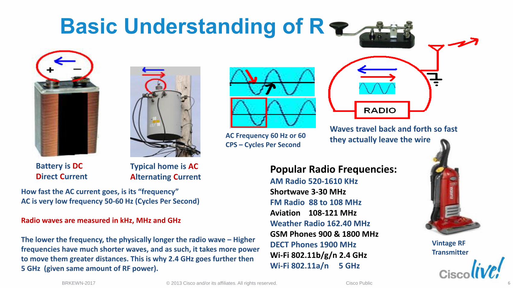
Basic Understanding of Radio…
Vintage RF Transmitter
Battery is DC Direct Current
Typical home is AC Alternating Current
AC Frequency 60 Hz or 60 CPS – Cycles Per Second
Waves travel back and forth so fast they actually leave the wire
Popular Radio Frequencies: AM Radio 520-1610 KHz Shortwave 3-30 MHz FM Radio 88 to 108 MHz Aviation 108-121 MHz Weather Radio 162.40 MHz GSM Phones 900 & 1800 MHz DECT Phones 1900 MHz Wi-Fi 802.11b/g/n 2.4 GHz Wi-Fi 802.11a/n 5 GHz
How fast the AC current goes, is its “frequency” AC is very low frequency 50-60 Hz (Cycles Per Second) Radio waves are measured in kHz, MHz and GHz The lower the frequency, the physically longer the radio wave – Higher frequencies have much shorter waves, and as such, it takes more power to move them greater distances. This is why 2.4 GHz goes further then 5 GHz (given same amount of RF power).
6
© 2013 Cisco and/or its affiliates. All rights reserved. BRKEWN-2017 Cisco Public
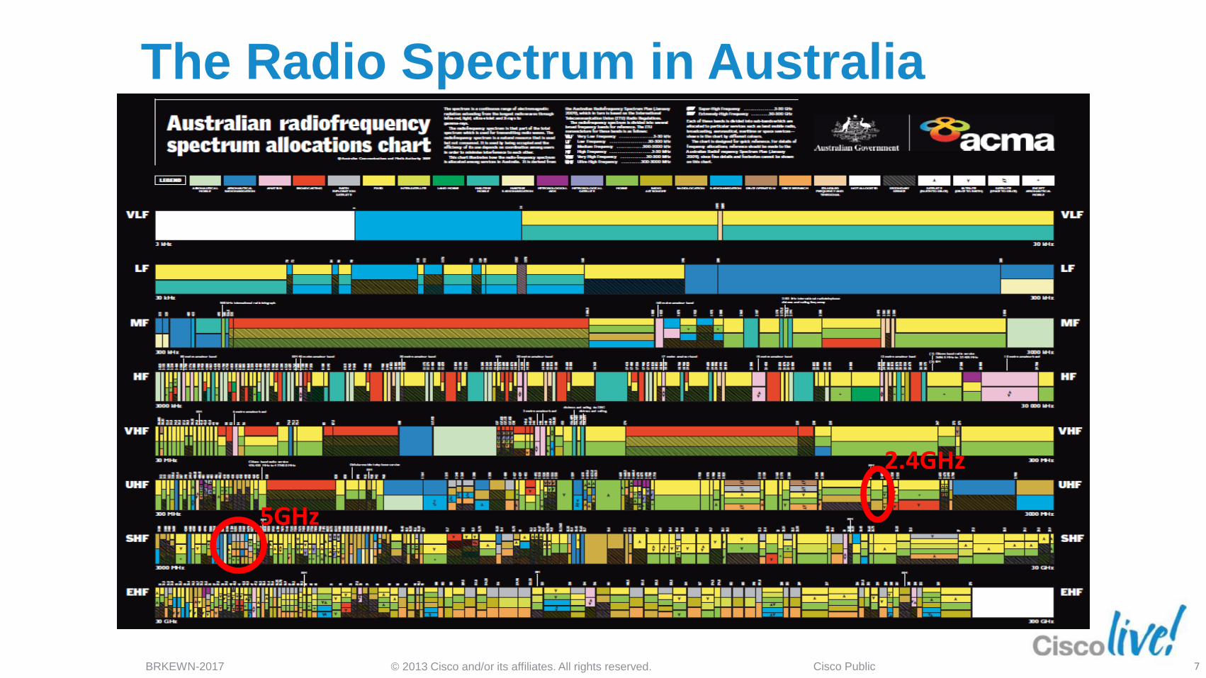
The Radio Spectrum in Australia
7
5GHz
2.4GHz
© 2013 Cisco and/or its affiliates. All rights reserved. BRKEWN-2017 Cisco Public
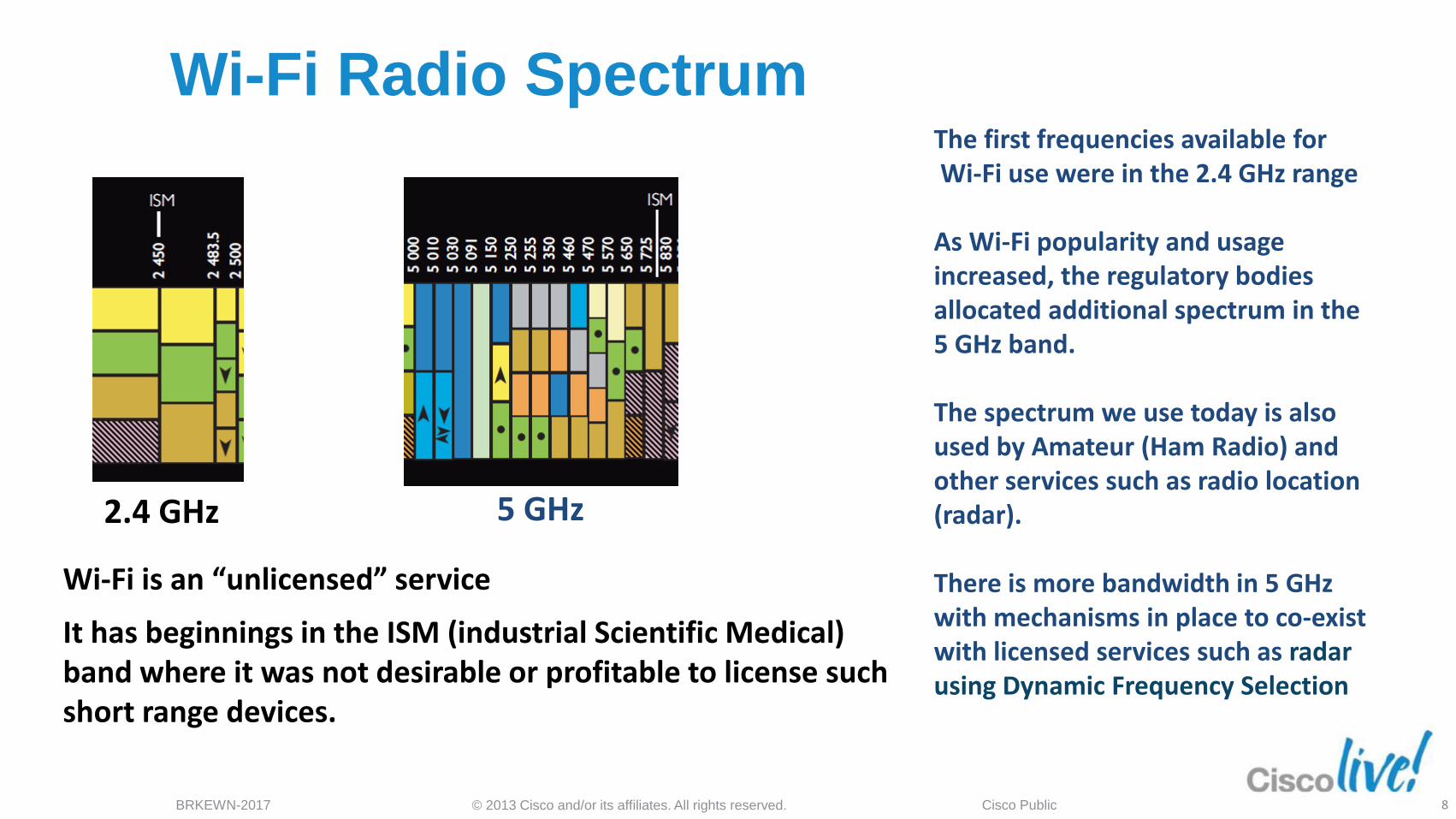
Wi-Fi Radio Spectrum
Wi-Fi is an “unlicensed” service
It has beginnings in the ISM (industrial Scientific Medical) band where it was not desirable or profitable to license such short range devices.
The first frequencies available for Wi-Fi use were in the 2.4 GHz range As Wi-Fi popularity and usage increased, the regulatory bodies allocated additional spectrum in the 5 GHz band. The spectrum we use today is also used by Amateur (Ham Radio) and other services such as radio location (radar). There is more bandwidth in 5 GHz with mechanisms in place to co-exist with licensed services such as radar using Dynamic Frequency Selection
2.4 GHz 5 GHz
8
© 2013 Cisco and/or its affiliates. All rights reserved. BRKEWN-2017 Cisco Public
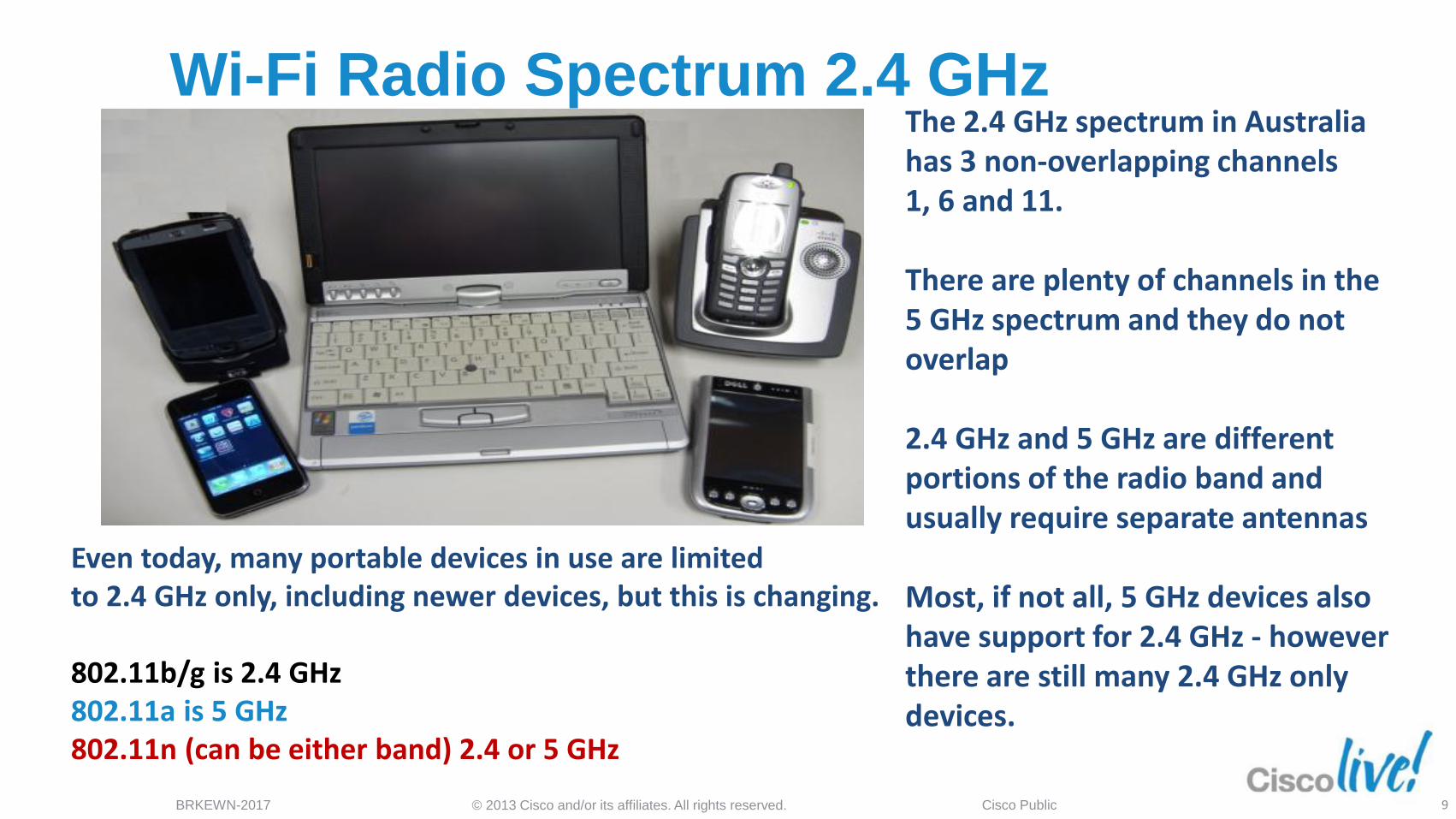
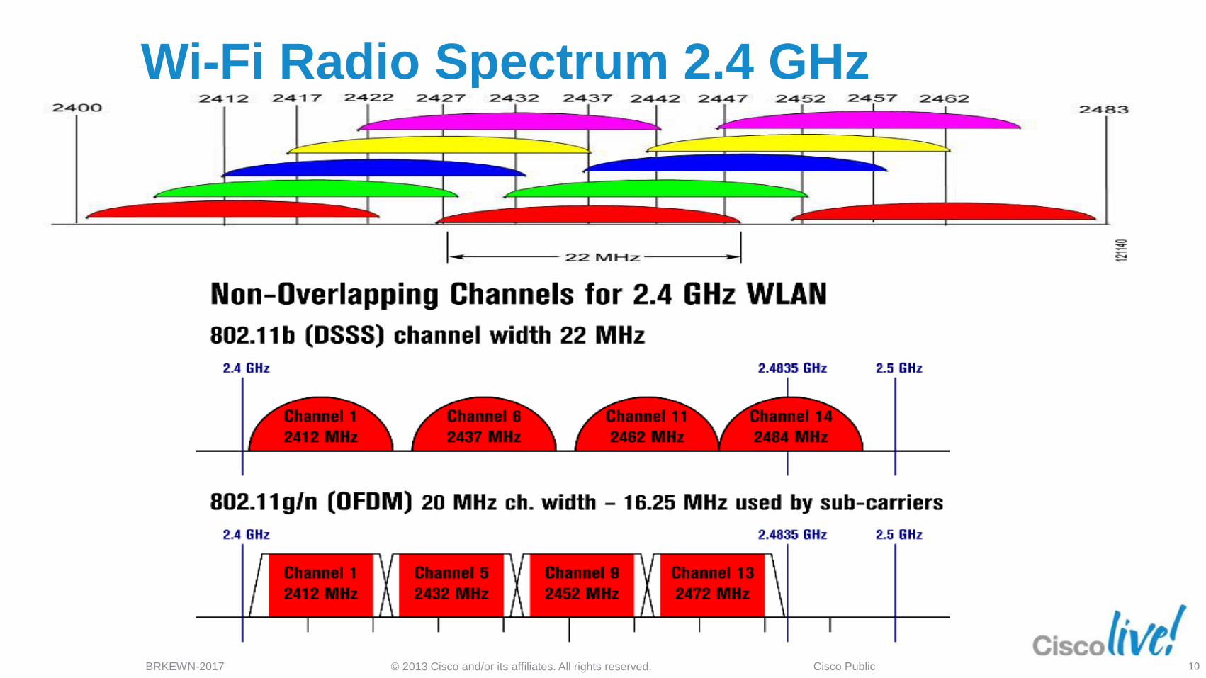
Wi-Fi Radio Spectrum 2.4 GHz
Even today, many portable devices in use are limited to 2.4 GHz only, including newer devices, but this is changing. 802.11b/g is 2.4 GHz 802.11a is 5 GHz 802.11n (can be either band) 2.4 or 5 GHz
The 2.4 GHz spectrum in Australia has 3 non-overlapping channels 1, 6 and 11. There are plenty of channels in the 5 GHz spectrum and they do not overlap 2.4 GHz and 5 GHz are different portions of the radio band and usually require separate antennas Most, if not all, 5 GHz devices also have support for 2.4 GHz - however there are still many 2.4 GHz only devices.
9
© 2013 Cisco and/or its affiliates. All rights reserved. BRKEWN-2017 Cisco Public
Wi-Fi Radio Spectrum 2.4 GHz
10
© 2013 Cisco and/or its affiliates. All rights reserved. BRKEWN-2017 Cisco Public
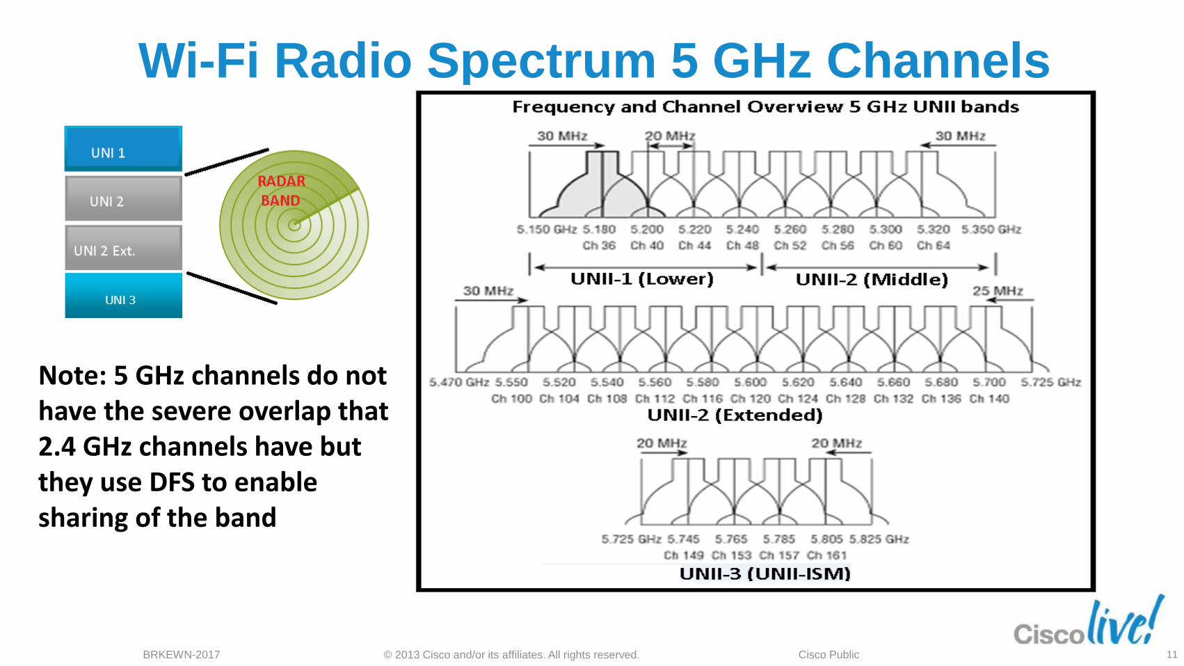
Wi-Fi Radio Spectrum 5 GHz Channels
Note: 5 GHz channels do not have the severe overlap that 2.4 GHz channels have but they use DFS to enable sharing of the band
11
© 2013 Cisco and/or its affiliates. All rights reserved. BRKEWN-2017 Cisco Public
Dynamic Frequency Selection (DFS) 5 GHz
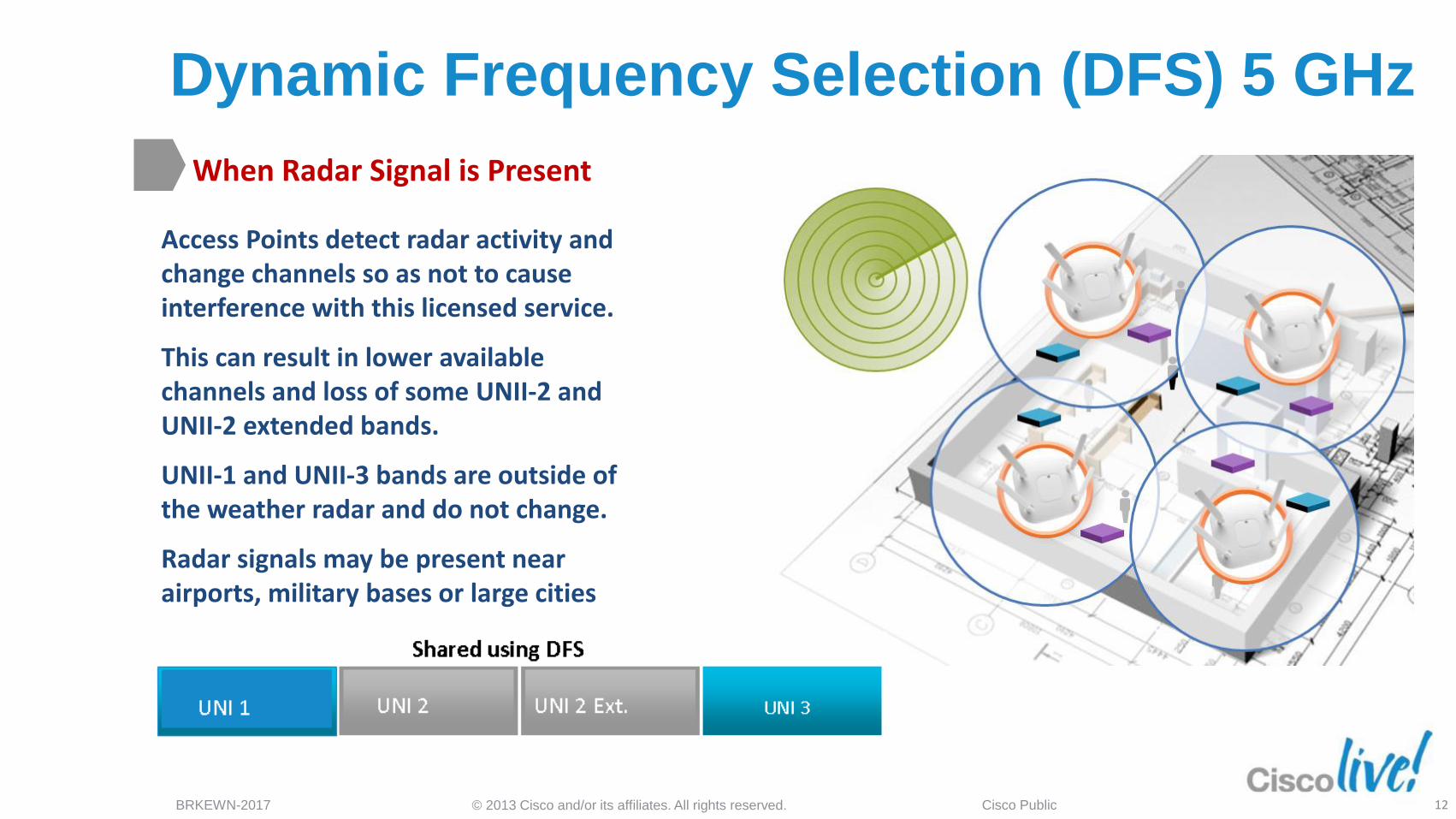
When Radar Signal is Present
Access Points detect radar activity and change channels so as not to cause interference with this licensed service.
This can result in lower available channels and loss of some UNII-2 and UNII-2 extended bands.
UNII-1 and UNII-3 bands are outside of the weather radar and do not change.
Radar signals may be present near airports, military bases or large cities
UNI 1 UN 3
12
© 2013 Cisco and/or its affiliates. All rights reserved. BRKEWN-2017 Cisco Public
A Radio Needs a Proper Antenna
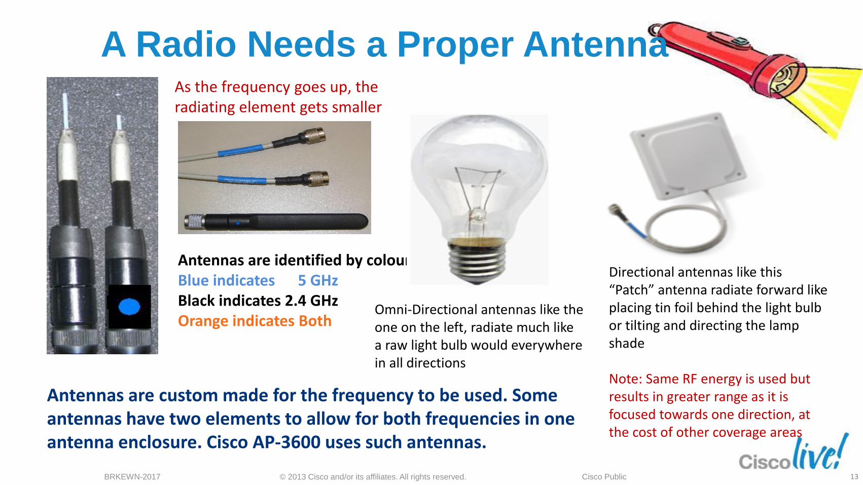
Antennas are identified by colour Blue indicates 5 GHz Black indicates 2.4 GHz Orange indicates Both
As the frequency goes up, the radiating element gets smaller
Antennas are custom made for the frequency to be used. Some antennas have two elements to allow for both frequencies in one antenna enclosure. Cisco AP-3600 uses such antennas.
Omni-Directional antennas like the one on the left, radiate much like a raw light bulb would everywhere in all directions
Directional antennas like this “Patch” antenna radiate forward like placing tin foil behind the light bulb or tilting and directing the lamp shade Note: Same RF energy is used but results in greater range as it is focused towards one direction, at the cost of other coverage areas
13
Basic 802.11 RF Terminology
Hardware Identification
© 2013 Cisco and/or its affiliates. All rights reserved. BRKEWN-2017 Cisco Public
Common RF Terms
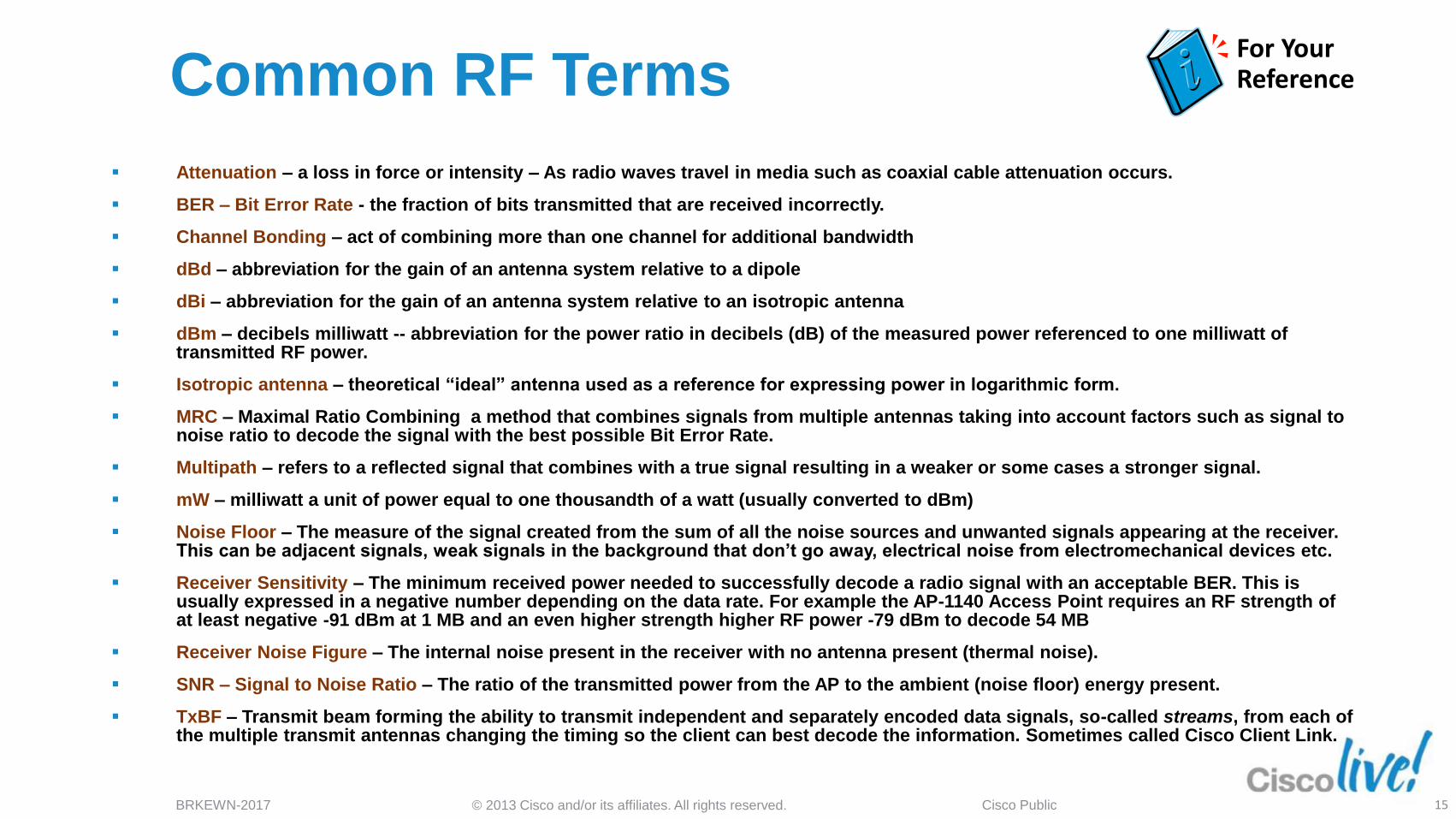
Attenuation – a loss in force or intensity – As radio waves travel in media such as coaxial cable attenuation occurs.
BER – Bit Error Rate - the fraction of bits transmitted that are received incorrectly.
Channel Bonding – act of combining more than one channel for additional bandwidth
dBd – abbreviation for the gain of an antenna system relative to a dipole
dBi – abbreviation for the gain of an antenna system relative to an isotropic antenna
dBm – decibels milliwatt -- abbreviation for the power ratio in decibels (dB) of the measured power referenced to one milliwatt of transmitted RF power.
Isotropic antenna – theoretical “ideal” antenna used as a reference for expressing power in logarithmic form.
MRC – Maximal Ratio Combining a method that combines signals from multiple antennas taking into account factors such as signal to noise ratio to decode the signal with the best possible Bit Error Rate.
Multipath – refers to a reflected signal that combines with a true signal resulting in a weaker or some cases a stronger signal.
mW – milliwatt a unit of power equal to one thousandth of a watt (usually converted to dBm)
Noise Floor – The measure of the signal created from the sum of all the noise sources and unwanted signals appearing at the receiver. This can be adjacent signals, weak signals in the background that don’t go away, electrical noise from electromechanical devices etc.
Receiver Sensitivity – The minimum received power needed to successfully decode a radio signal with an acceptable BER. This is usually expressed in a negative number depending on the data rate. For example the AP-1140 Access Point requires an RF strength of at least negative -91 dBm at 1 MB and an even higher strength higher RF power -79 dBm to decode 54 MB
Receiver Noise Figure – The internal noise present in the receiver with no antenna present (thermal noise).
SNR – Signal to Noise Ratio – The ratio of the transmitted power from the AP to the ambient (noise floor) energy present.
TxBF – Transmit beam forming the ability to transmit independent and separately encoded data signals, so-called streams, from each of the multiple transmit antennas changing the timing so the client can best decode the information. Sometimes called Cisco Client Link.
For Your Reference
15
© 2013 Cisco and/or its affiliates. All rights reserved. BRKEWN-2017 Cisco Public
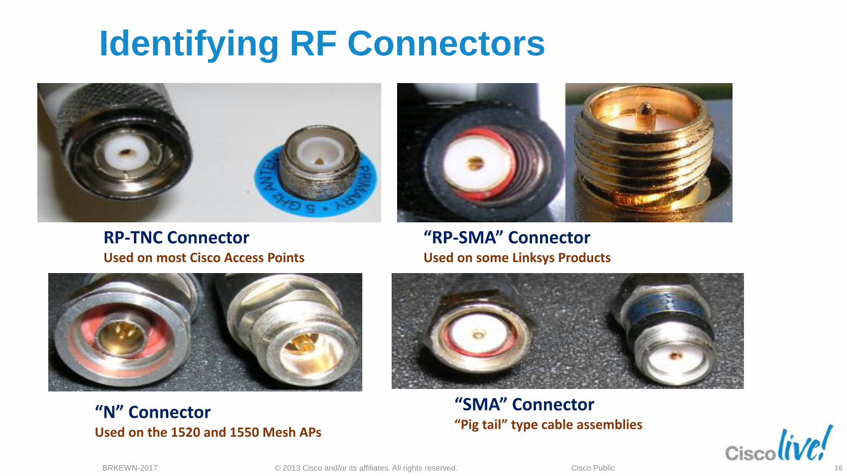
Identifying RF Connectors
RP-TNC Connector Used on most Cisco Access Points
“N” Connector Used on the 1520 and 1550 Mesh APs
“SMA” Connector “Pig tail” type cable assemblies
“RP-SMA” Connector Used on some Linksys Products
16
© 2013 Cisco and/or its affiliates. All rights reserved. BRKEWN-2017 Cisco Public
Antenna Cables – LMR Series
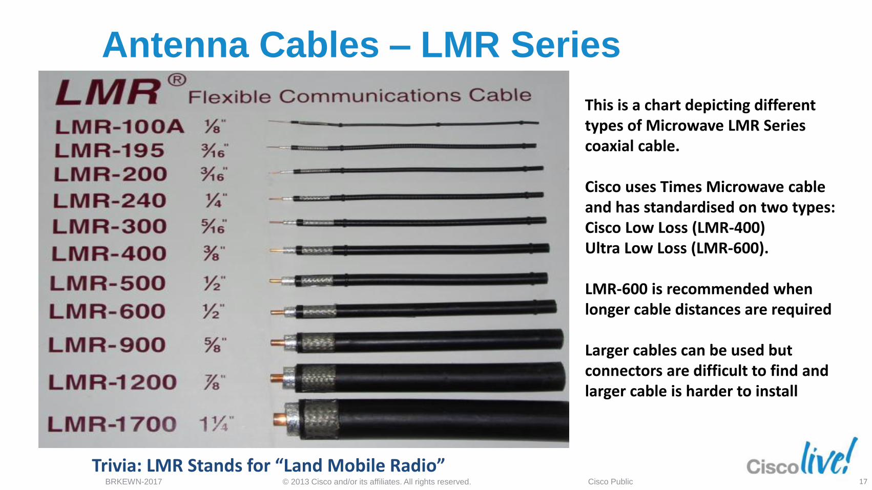
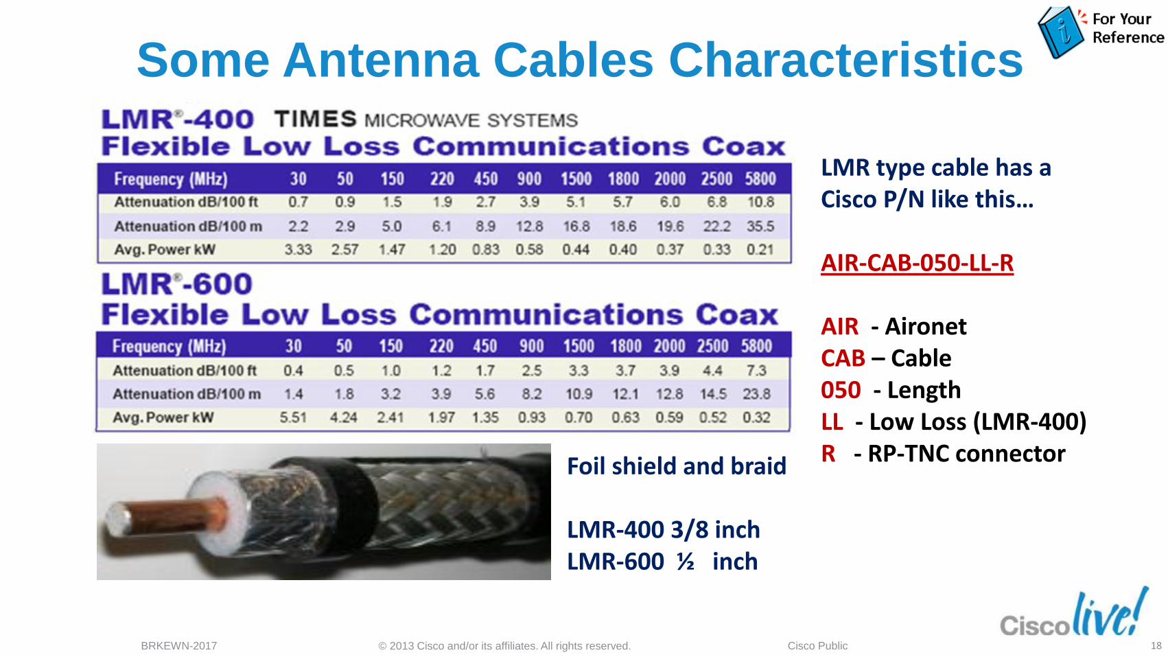
This is a chart depicting different types of Microwave LMR Series coaxial cable. Cisco uses Times Microwave cable and has standardised on two types: Cisco Low Loss (LMR-400) Ultra Low Loss (LMR-600). LMR-600 is recommended when longer cable distances are required Larger cables can be used but connectors are difficult to find and larger cable is harder to install
Trivia: LMR Stands for “Land Mobile Radio” 17
© 2013 Cisco and/or its affiliates. All rights reserved. BRKEWN-2017 Cisco Public
Some Antenna Cables Characteristics
Foil shield and braid LMR-400 3/8 inch LMR-600 ½ inch
LMR type cable has a Cisco P/N like this… AIR-CAB-050-LL-R AIR - Aironet CAB – Cable 050 - Length LL - Low Loss (LMR-400) R - RP-TNC connector
18
802.11 Antenna Basics
© 2013 Cisco and/or its affiliates. All rights reserved. BRKEWN-2017 Cisco Public
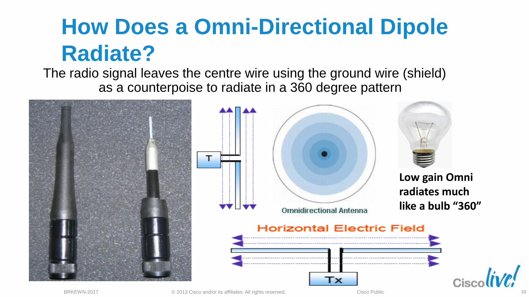
How Does a Omni-Directional Dipole
Radiate? The radio signal leaves the centre wire using the ground wire (shield)
as a counterpoise to radiate in a 360 degree pattern
Low gain Omni radiates much like a bulb “360”
20
© 2013 Cisco and/or its affiliates. All rights reserved. BRKEWN-2017 Cisco Public
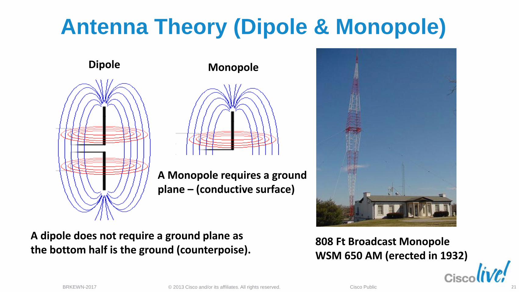
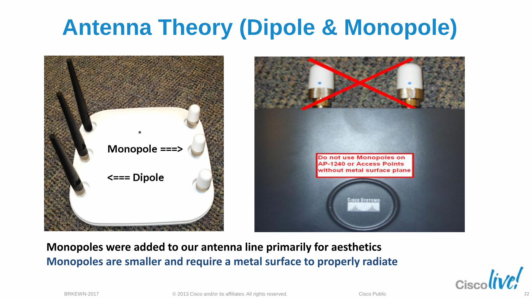
Dipole
A dipole does not require a ground plane as the bottom half is the ground (counterpoise).
Monopole
A Monopole requires a ground plane – (conductive surface)
808 Ft Broadcast Monopole WSM 650 AM (erected in 1932)
Antenna Theory (Dipole & Monopole)
21
© 2013 Cisco and/or its affiliates. All rights reserved. BRKEWN-2017 Cisco Public
Monopoles were added to our antenna line primarily for aesthetics Monopoles are smaller and require a metal surface to properly radiate
Antenna Theory (Dipole & Monopole)
22
© 2013 Cisco and/or its affiliates. All rights reserved. BRKEWN-2017 Cisco Public
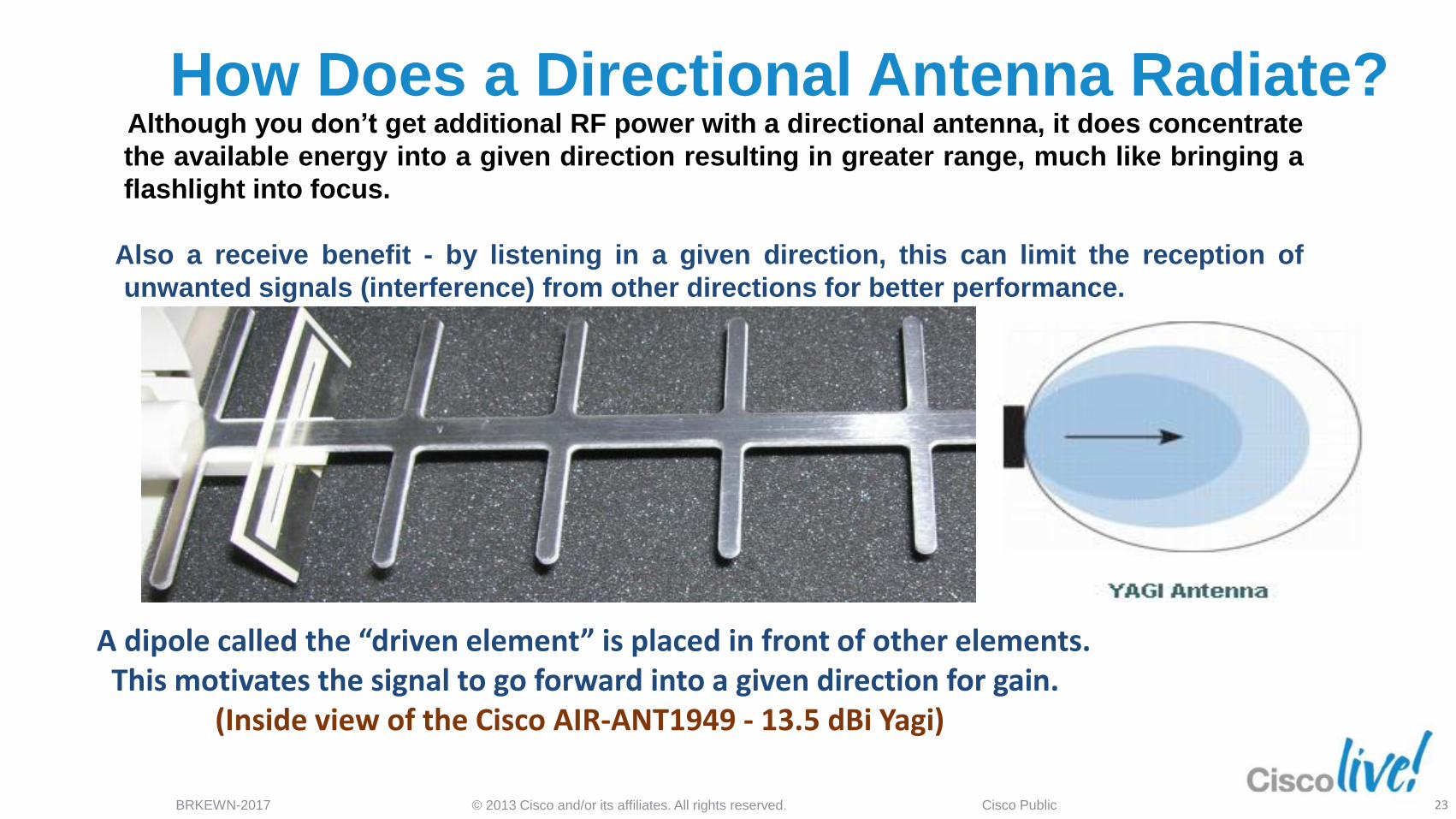
How Does a Directional Antenna Radiate? Although you don’t get additional RF power with a directional antenna, it does concentrate
the available energy into a given direction resulting in greater range, much like bringing a
flashlight into focus.
Also a receive benefit - by listening in a given direction, this can limit the reception of
unwanted signals (interference) from other directions for better performance.
A dipole called the “driven element” is placed in front of other elements. This motivates the signal to go forward into a given direction for gain. (Inside view of the Cisco AIR-ANT1949 - 13.5 dBi Yagi)
23
© 2013 Cisco and/or its affiliates. All rights reserved. BRKEWN-2017 Cisco Public
Patch Antenna: a Look Inside
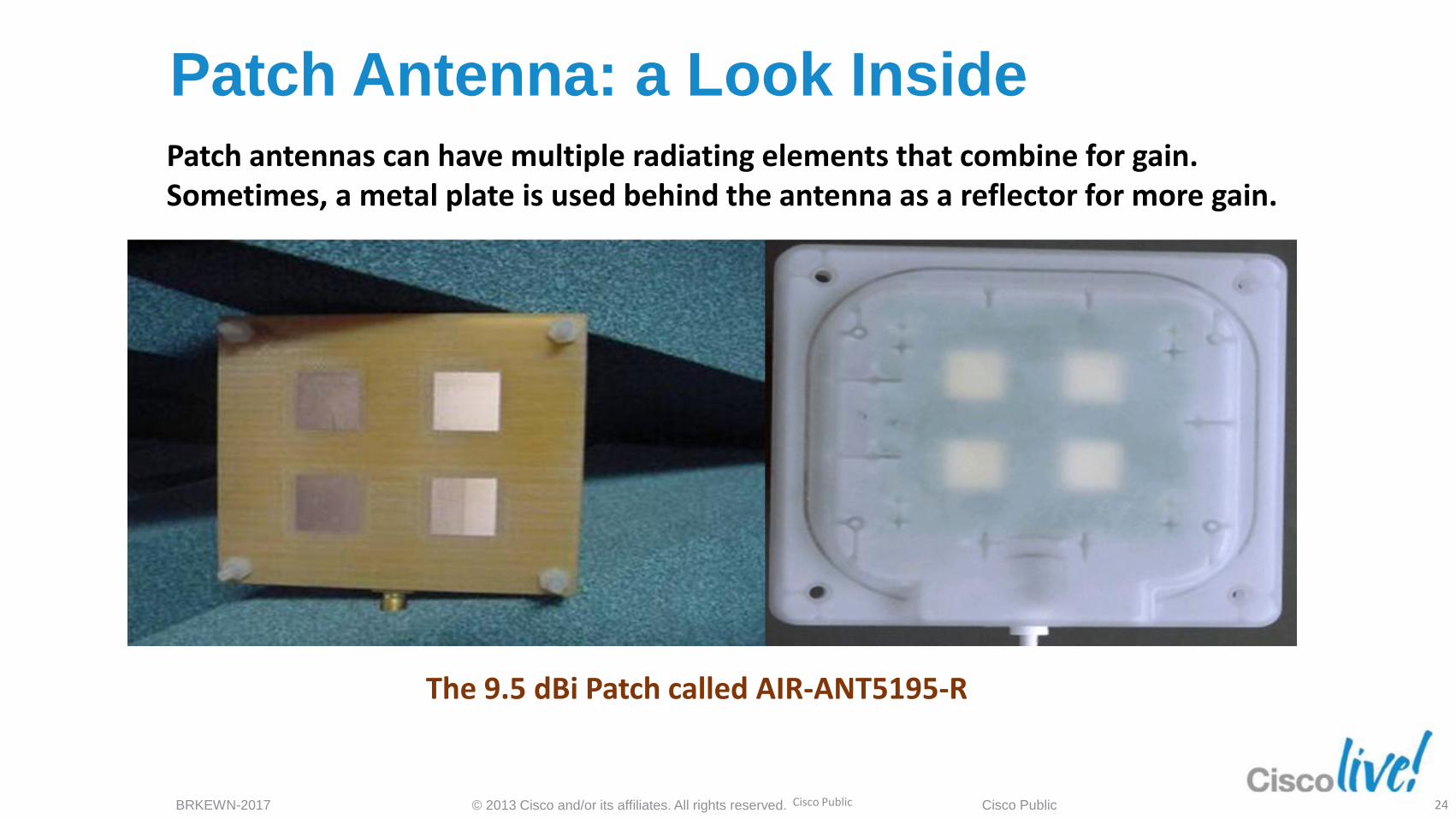
The 9.5 dBi Patch called AIR-ANT5195-R
Patch antennas can have multiple radiating elements that combine for gain. Sometimes, a metal plate is used behind the antenna as a reflector for more gain.
Cisco Public 24
© 2013 Cisco and/or its affiliates. All rights reserved. BRKEWN-2017 Cisco Public
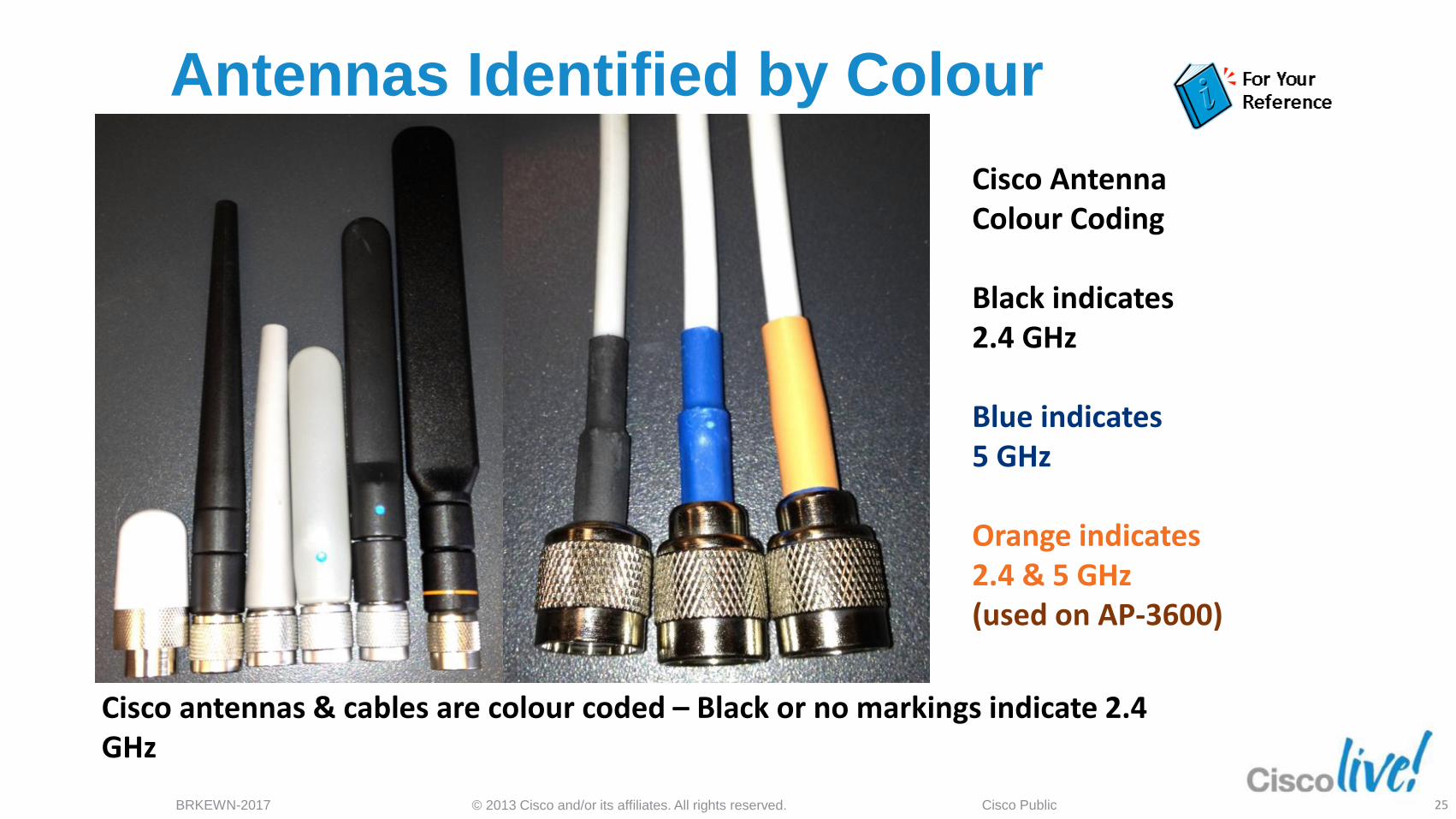
Antennas Identified by Colour
Cisco Antenna Colour Coding Black indicates 2.4 GHz Blue indicates 5 GHz Orange indicates 2.4 & 5 GHz (used on AP-3600)
Cisco antennas & cables are colour coded – Black or no markings indicate 2.4 GHz
25
© 2013 Cisco and/or its affiliates. All rights reserved. BRKEWN-2017 Cisco Public
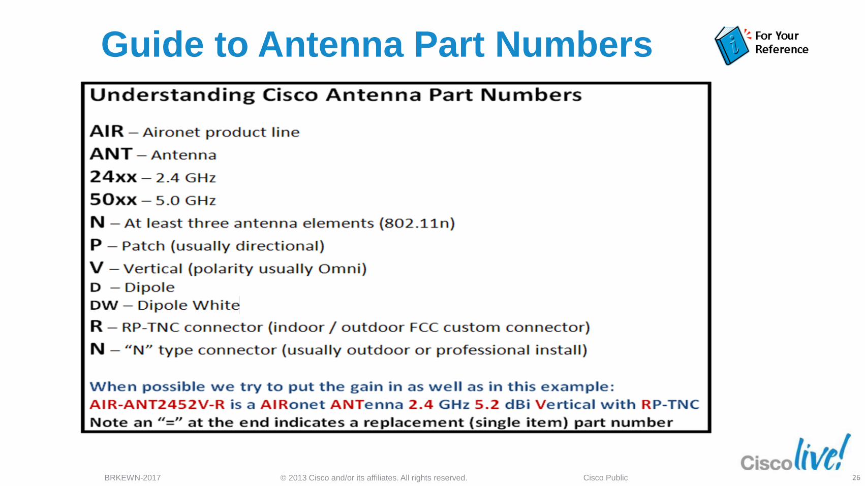
Guide to Antenna Part Numbers
26
© 2013 Cisco and/or its affiliates. All rights reserved. BRKEWN-2017 Cisco Public
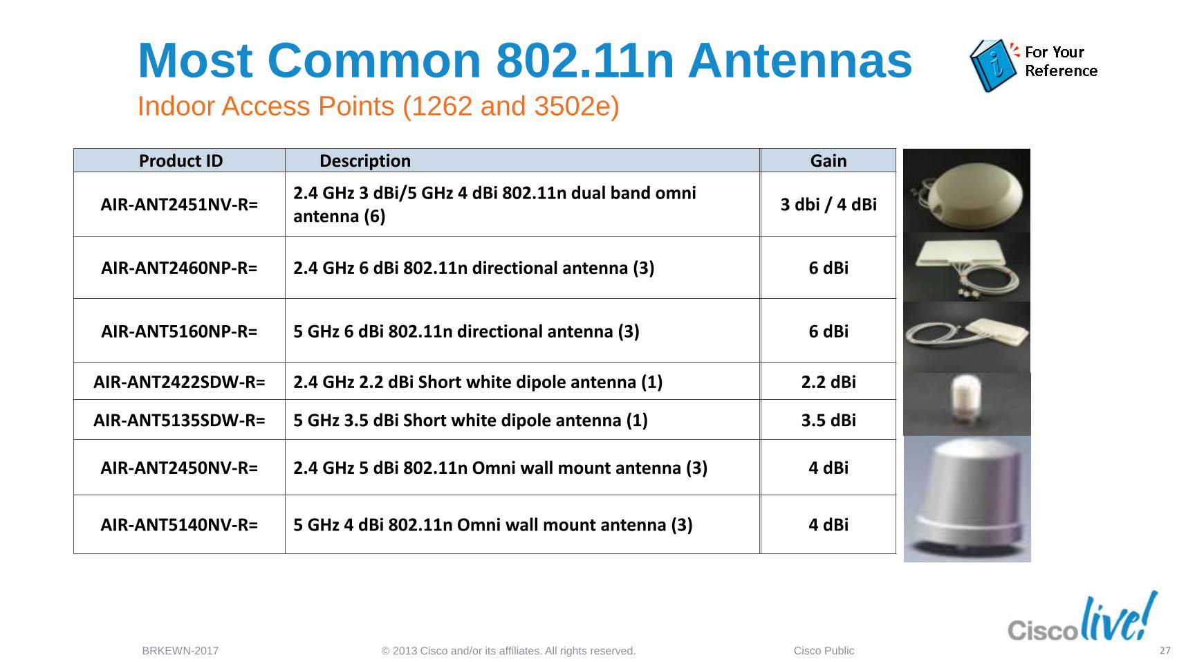
Product ID Description Gain
AIR-ANT2451NV-R= 2.4 GHz 3 dBi/5 GHz 4 dBi 802.11n dual band omni antenna (6)
3 dbi / 4 dBi
AIR-ANT2460NP-R= 2.4 GHz 6 dBi 802.11n directional antenna (3)
6 dBi
AIR-ANT5160NP-R= 5 GHz 6 dBi 802.11n directional antenna (3)
6 dBi
AIR-ANT2422SDW-R= 2.4 GHz 2.2 dBi Short white dipole antenna (1) 2.2 dBi
AIR-ANT5135SDW-R= 5 GHz 3.5 dBi Short white dipole antenna (1) 3.5 dBi
AIR-ANT2450NV-R= 2.4 GHz 5 dBi 802.11n Omni wall mount antenna (3)
4 dBi
AIR-ANT5140NV-R= 5 GHz 4 dBi 802.11n Omni wall mount antenna (3)
4 dBi
Most Common 802.11n Antennas Indoor Access Points (1262 and 3502e)
27
© 2013 Cisco and/or its affiliates. All rights reserved. BRKEWN-2017 Cisco Public
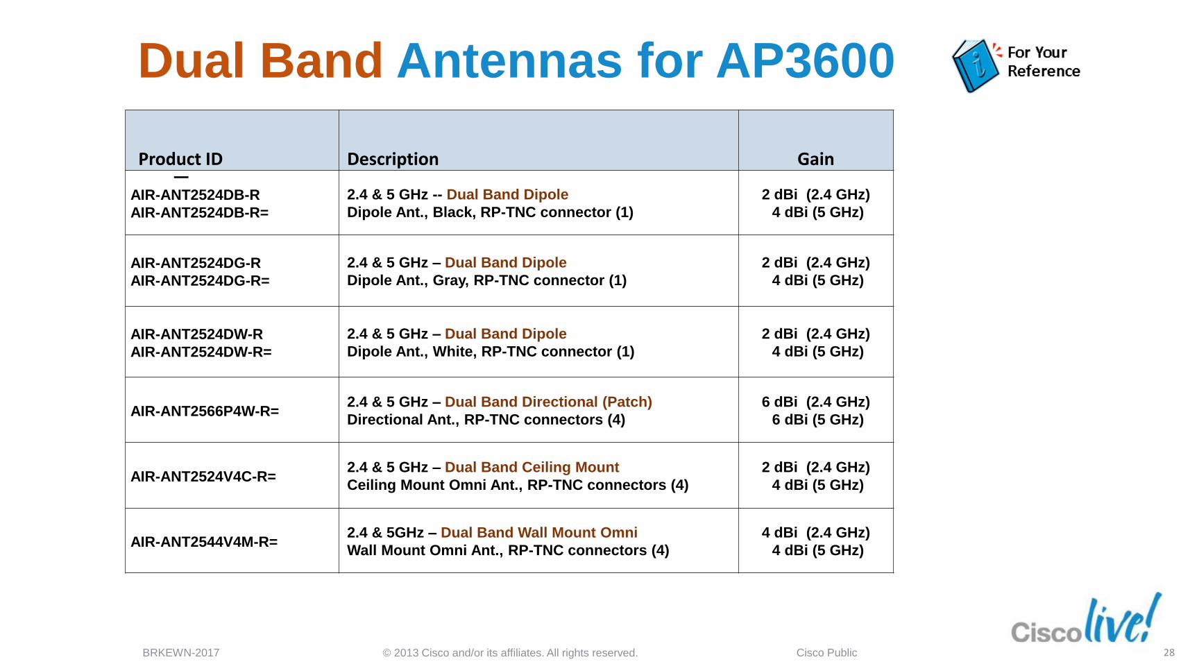
Dual Band Antennas for AP3600
‒
Product ID Description Gain
AIR-ANT2524DB-R
AIR-ANT2524DB-R=
2.4 & 5 GHz -- Dual Band Dipole
Dipole Ant., Black, RP-TNC connector (1)
2 dBi (2.4 GHz)
4 dBi (5 GHz)
AIR-ANT2524DG-R
AIR-ANT2524DG-R=
2.4 & 5 GHz – Dual Band Dipole
Dipole Ant., Gray, RP-TNC connector (1)
2 dBi (2.4 GHz)
4 dBi (5 GHz)
AIR-ANT2524DW-R
AIR-ANT2524DW-R=
2.4 & 5 GHz – Dual Band Dipole
Dipole Ant., White, RP-TNC connector (1)
2 dBi (2.4 GHz)
4 dBi (5 GHz)
AIR-ANT2566P4W-R= 2.4 & 5 GHz – Dual Band Directional (Patch)
Directional Ant., RP-TNC connectors (4)
6 dBi (2.4 GHz)
6 dBi (5 GHz)
AIR-ANT2524V4C-R= 2.4 & 5 GHz – Dual Band Ceiling Mount
Ceiling Mount Omni Ant., RP-TNC connectors (4)
2 dBi (2.4 GHz)
4 dBi (5 GHz)
AIR-ANT2544V4M-R= 2.4 & 5GHz – Dual Band Wall Mount Omni
Wall Mount Omni Ant., RP-TNC connectors (4)
4 dBi (2.4 GHz)
4 dBi (5 GHz)
28
Understanding and Interpreting
Antenna Patterns
© 2013 Cisco and/or its affiliates. All rights reserved. BRKEWN-2017 Cisco Public
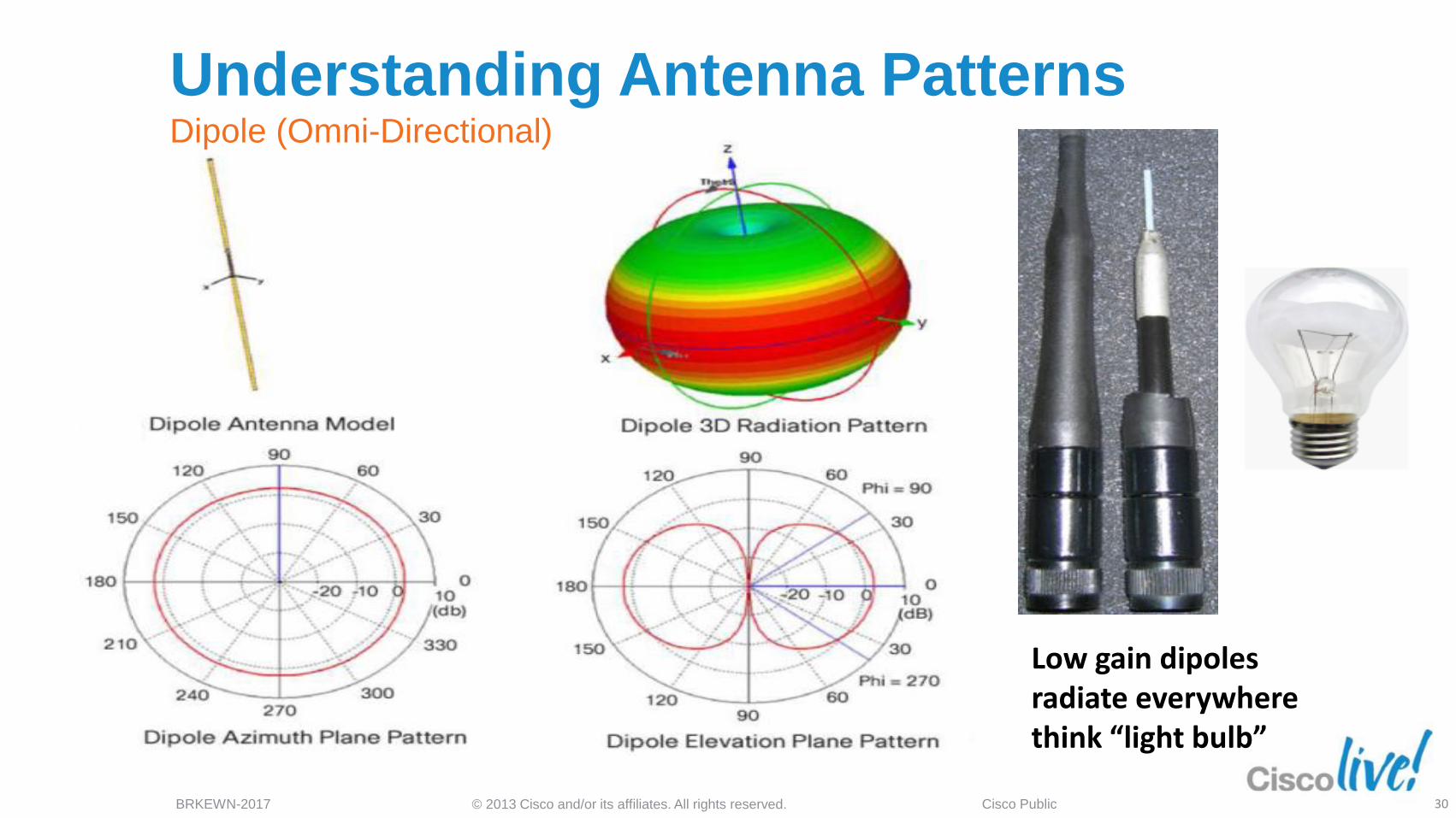
Low gain dipoles radiate everywhere think “light bulb”
Understanding Antenna Patterns Dipole (Omni-Directional)
30
© 2013 Cisco and/or its affiliates. All rights reserved. BRKEWN-2017 Cisco Public
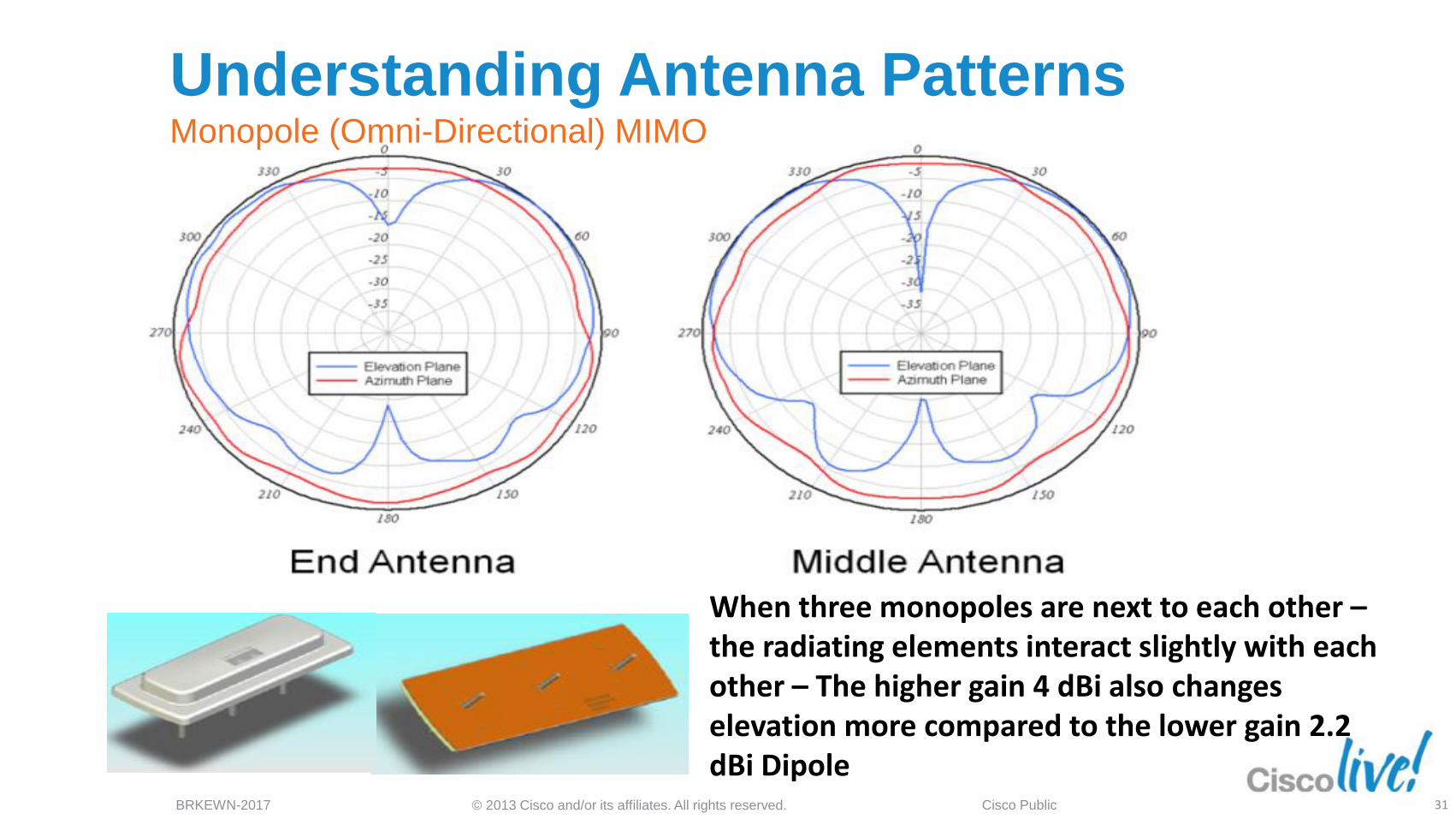
When three monopoles are next to each other – the radiating elements interact slightly with each other – The higher gain 4 dBi also changes elevation more compared to the lower gain 2.2 dBi Dipole
Understanding Antenna Patterns Monopole (Omni-Directional) MIMO
31
© 2013 Cisco and/or its affiliates. All rights reserved. BRKEWN-2017 Cisco Public
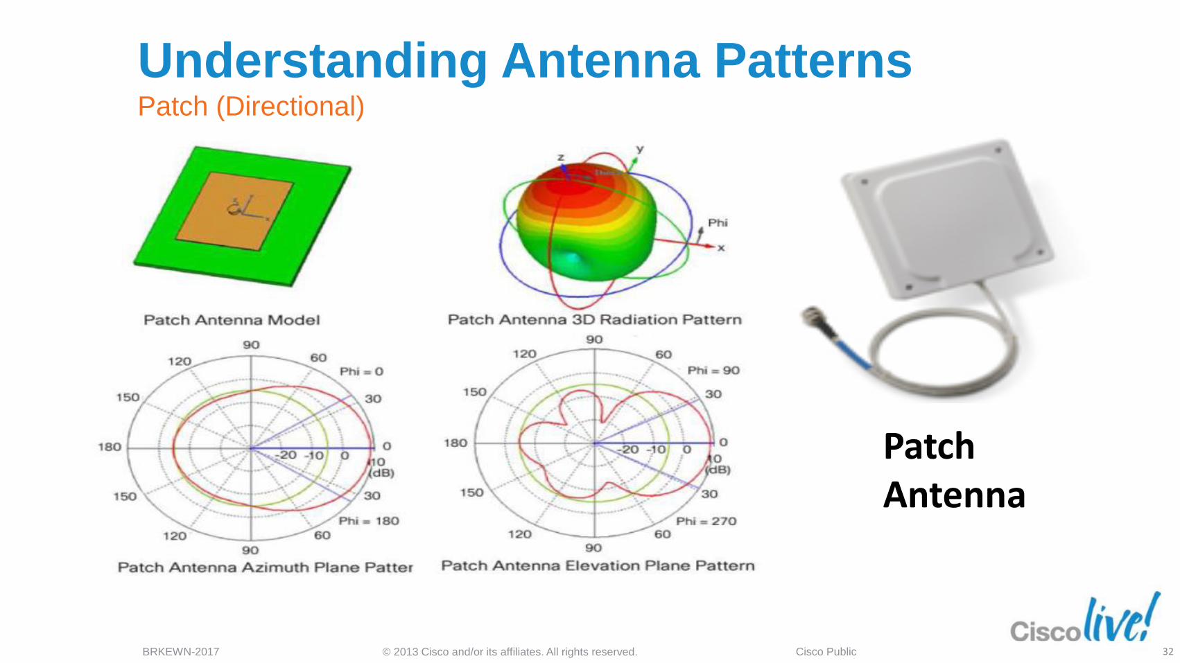
Patch Antenna
Understanding Antenna Patterns Patch (Directional)
32
© 2013 Cisco and/or its affiliates. All rights reserved. BRKEWN-2017 Cisco Public
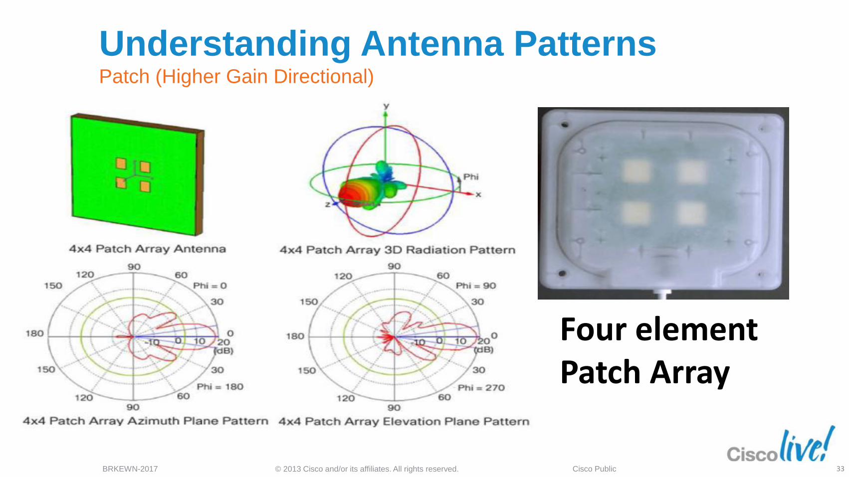
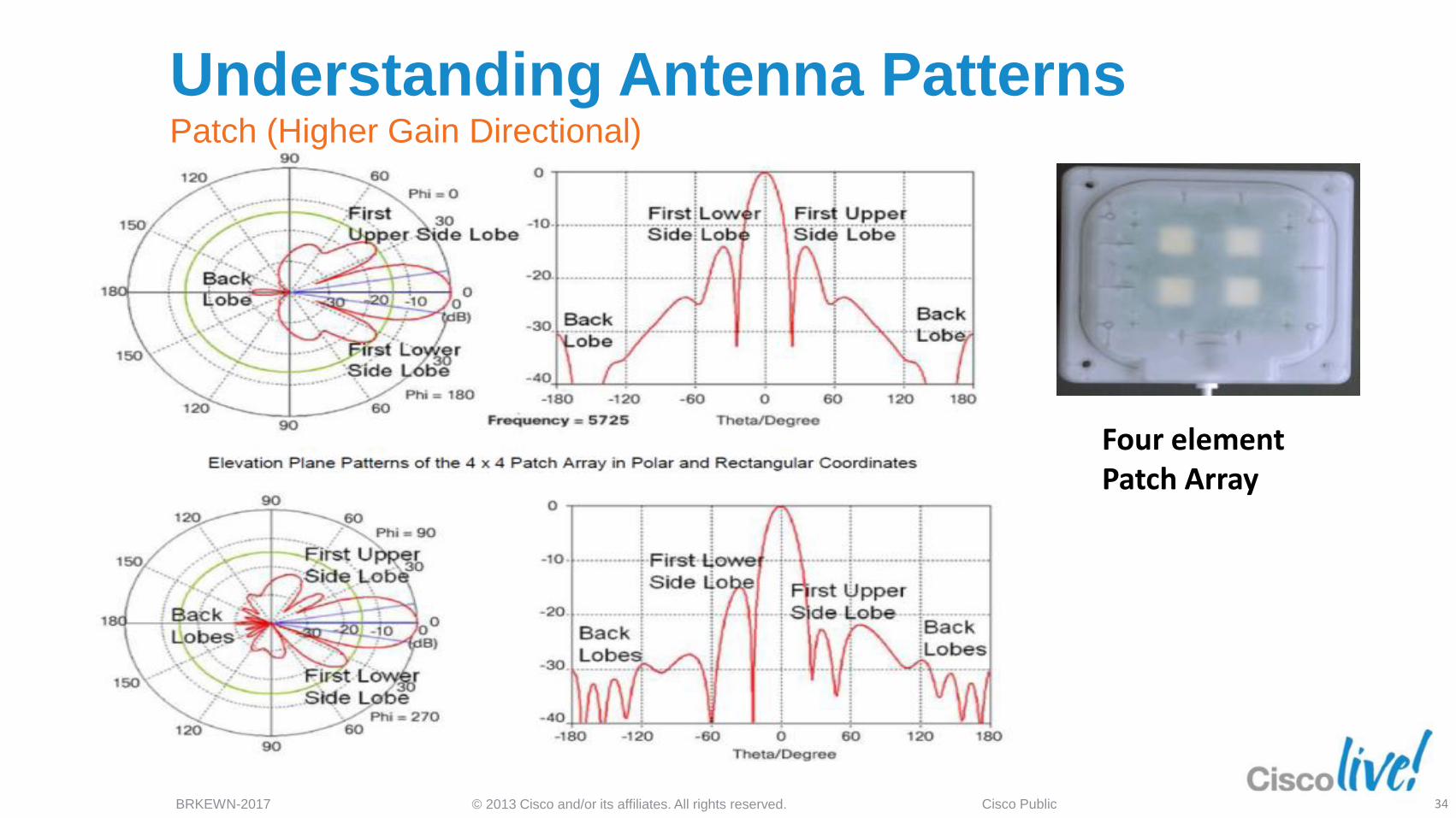
Four element Patch Array
Understanding Antenna Patterns Patch (Higher Gain Directional)
33
© 2013 Cisco and/or its affiliates. All rights reserved. BRKEWN-2017 Cisco Public
Four element Patch Array
Understanding Antenna Patterns Patch (Higher Gain Directional)
34
© 2013 Cisco and/or its affiliates. All rights reserved. BRKEWN-2017 Cisco Public
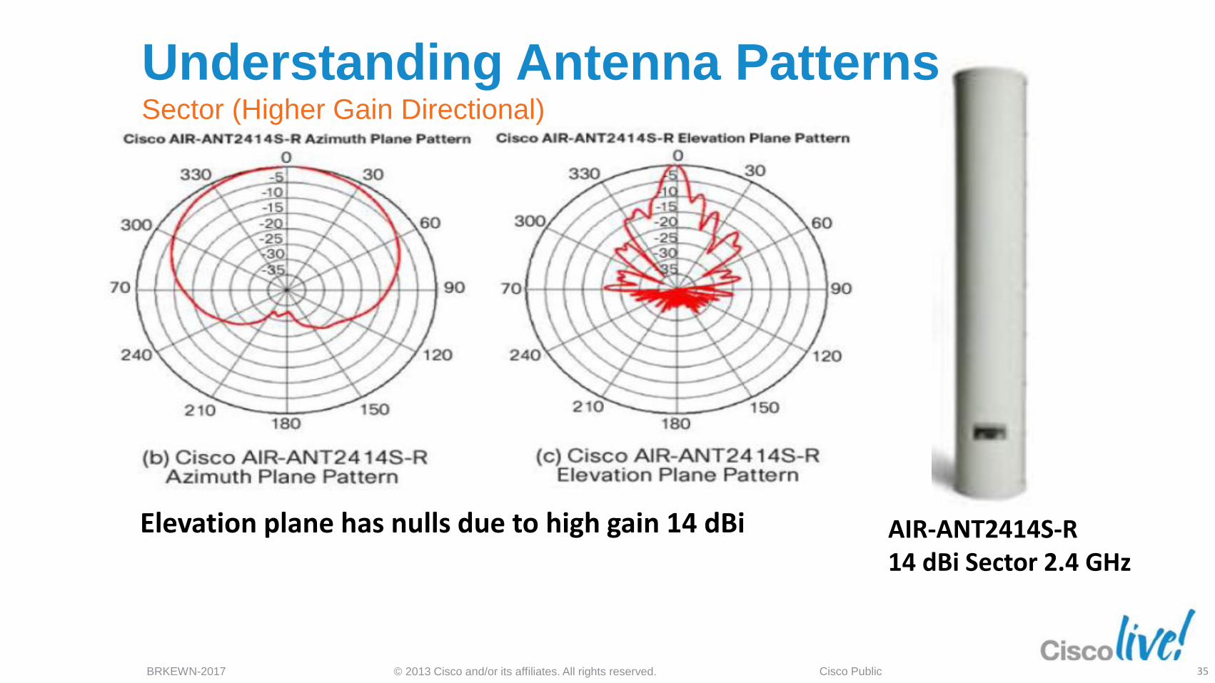
Elevation plane has nulls due to high gain 14 dBi AIR-ANT2414S-R 14 dBi Sector 2.4 GHz
Understanding Antenna Patterns Sector (Higher Gain Directional)
35
© 2013 Cisco and/or its affiliates. All rights reserved. BRKEWN-2017 Cisco Public
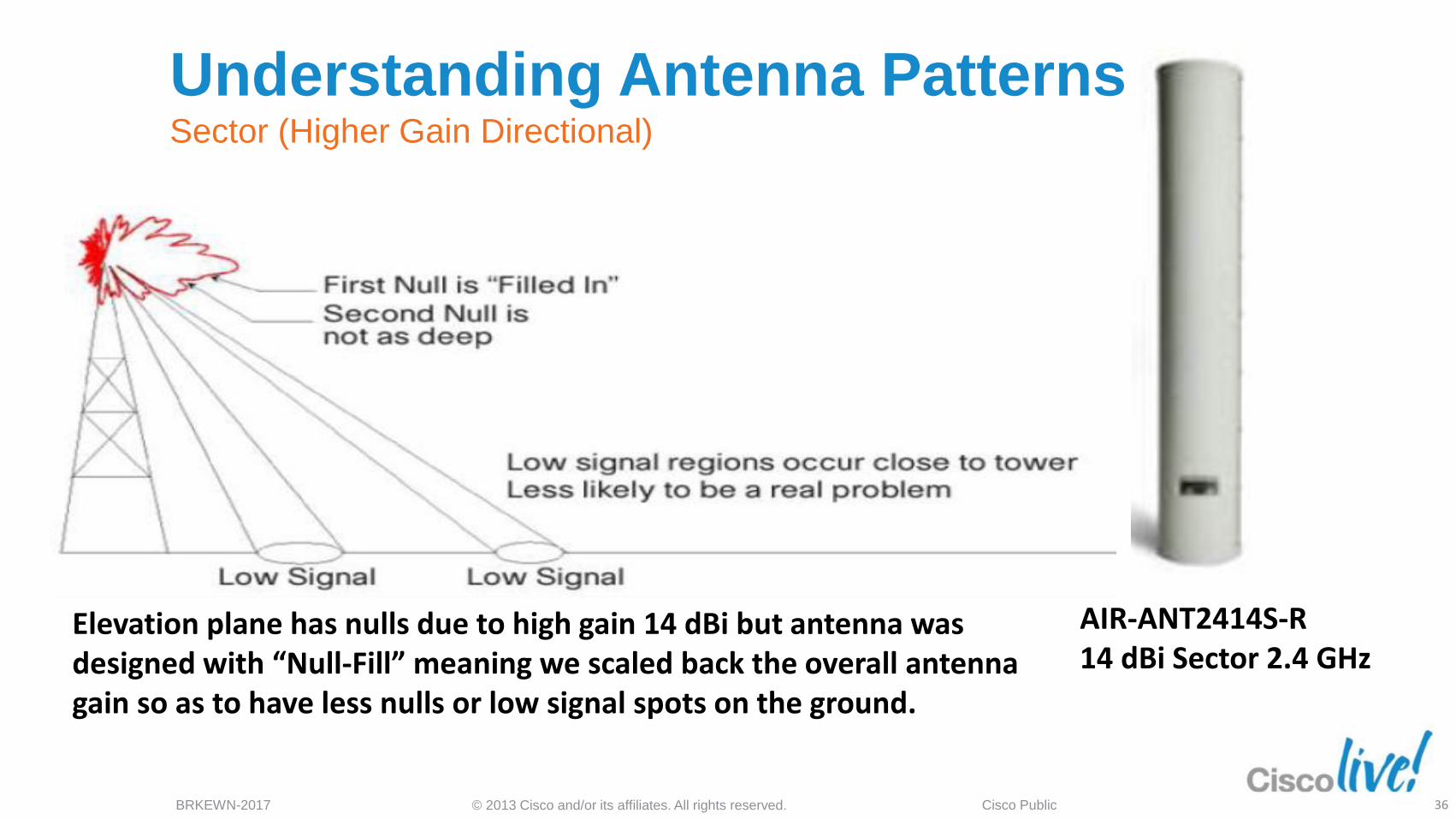
AIR-ANT2414S-R 14 dBi Sector 2.4 GHz
Elevation plane has nulls due to high gain 14 dBi but antenna was designed with “Null-Fill” meaning we scaled back the overall antenna gain so as to have less nulls or low signal spots on the ground.
Understanding Antenna Patterns Sector (Higher Gain Directional)
36
© 2013 Cisco and/or its affiliates. All rights reserved. BRKEWN-2017 Cisco Public
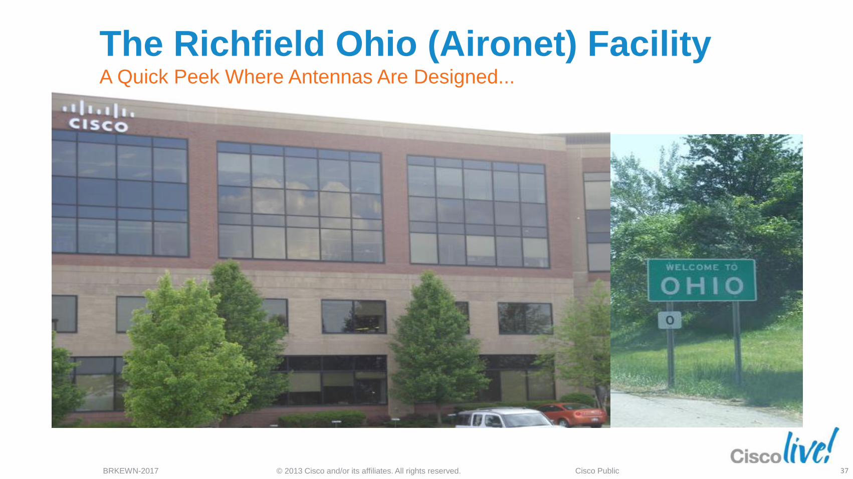
The Richfield Ohio (Aironet) Facility A Quick Peek Where Antennas Are Designed...
37
© 2013 Cisco and/or its affiliates. All rights reserved. BRKEWN-2017 Cisco Public
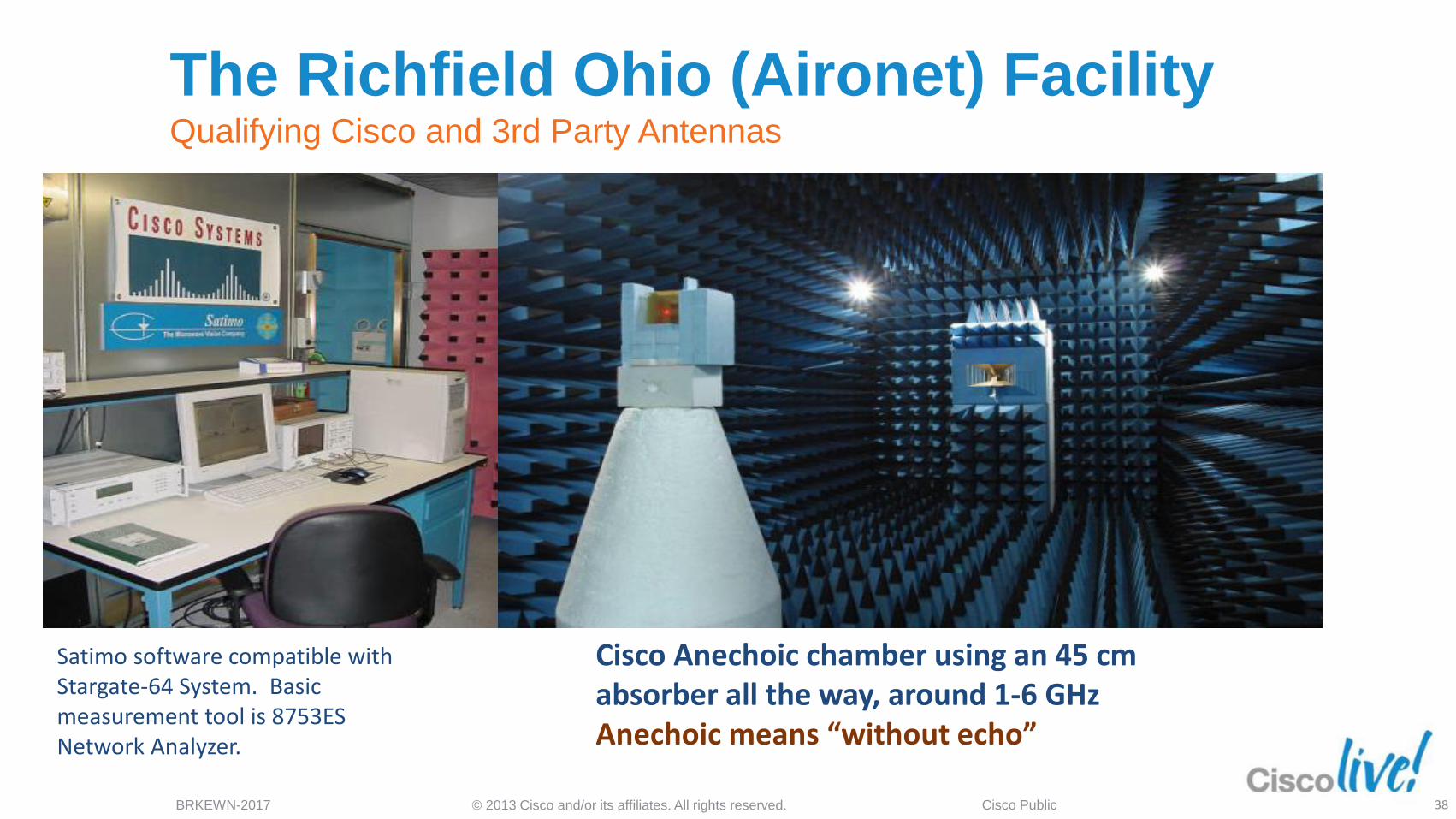
The Richfield Ohio (Aironet) Facility Qualifying Cisco and 3rd Party Antennas
Satimo software compatible with Stargate-64 System. Basic measurement tool is 8753ES Network Analyzer.
Cisco Anechoic chamber using an 45 cm absorber all the way, around 1-6 GHz Anechoic means “without echo”
38
© 2013 Cisco and/or its affiliates. All rights reserved. BRKEWN-2017 Cisco Public
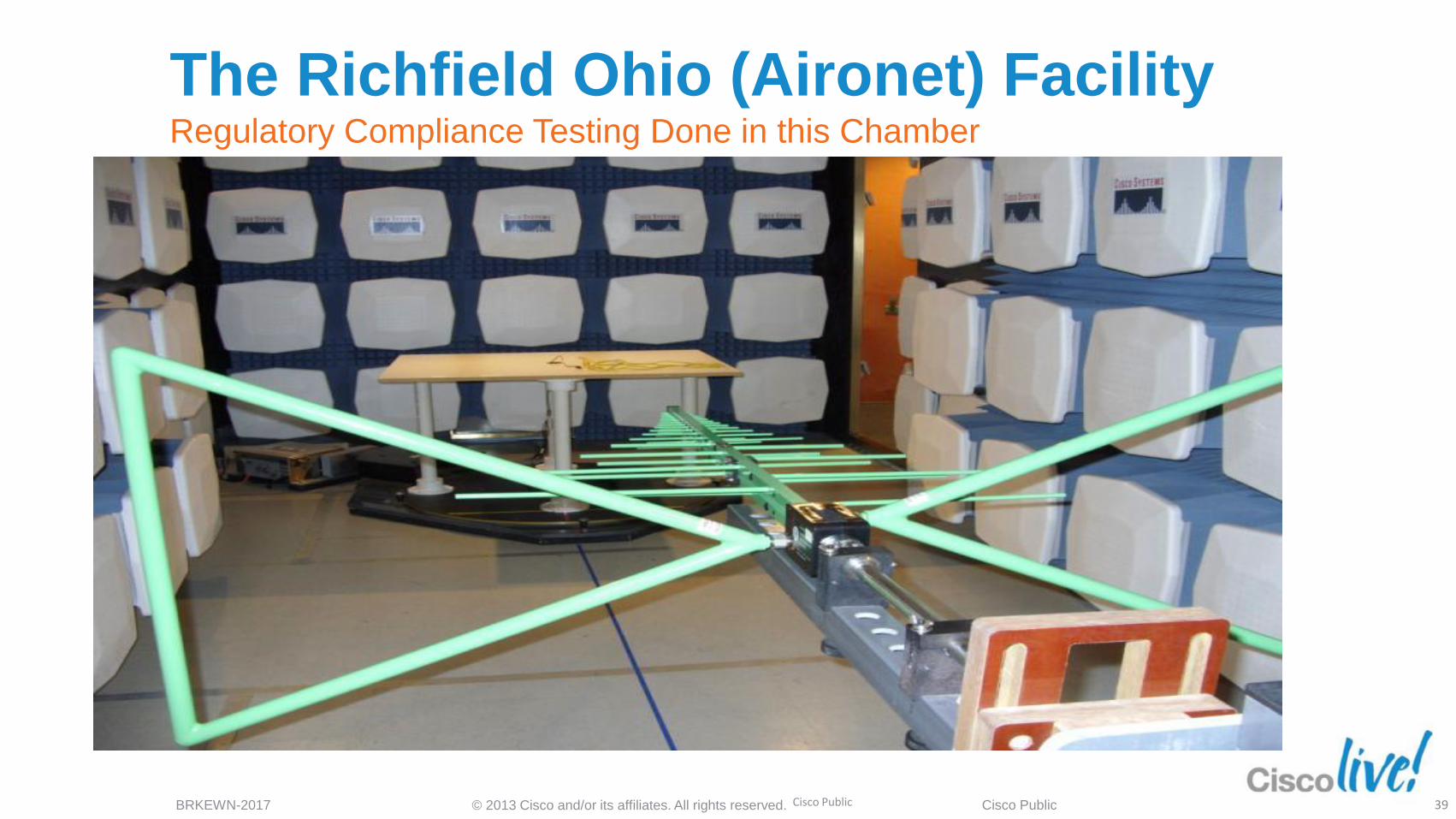
The Richfield Ohio (Aironet) Facility Regulatory Compliance Testing Done in this Chamber
Cisco Public 39
© 2013 Cisco and/or its affiliates. All rights reserved. BRKEWN-2017 Cisco Public
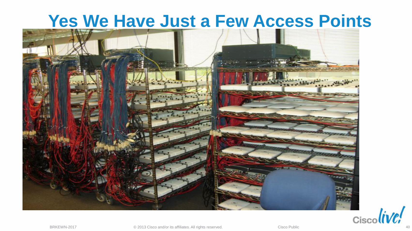
Yes We Have Just a Few Access Points
Running…
40
© 2013 Cisco and/or its affiliates. All rights reserved. BRKEWN-2017 Cisco Public
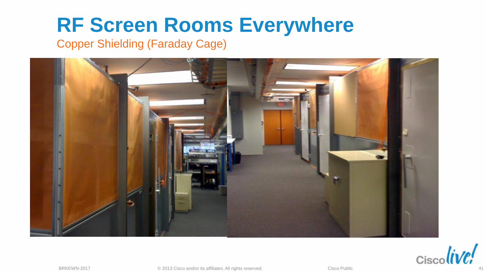
RF Screen Rooms Everywhere Copper Shielding (Faraday Cage)
41
© 2013 Cisco and/or its affiliates. All rights reserved. BRKEWN-2017 Cisco Public
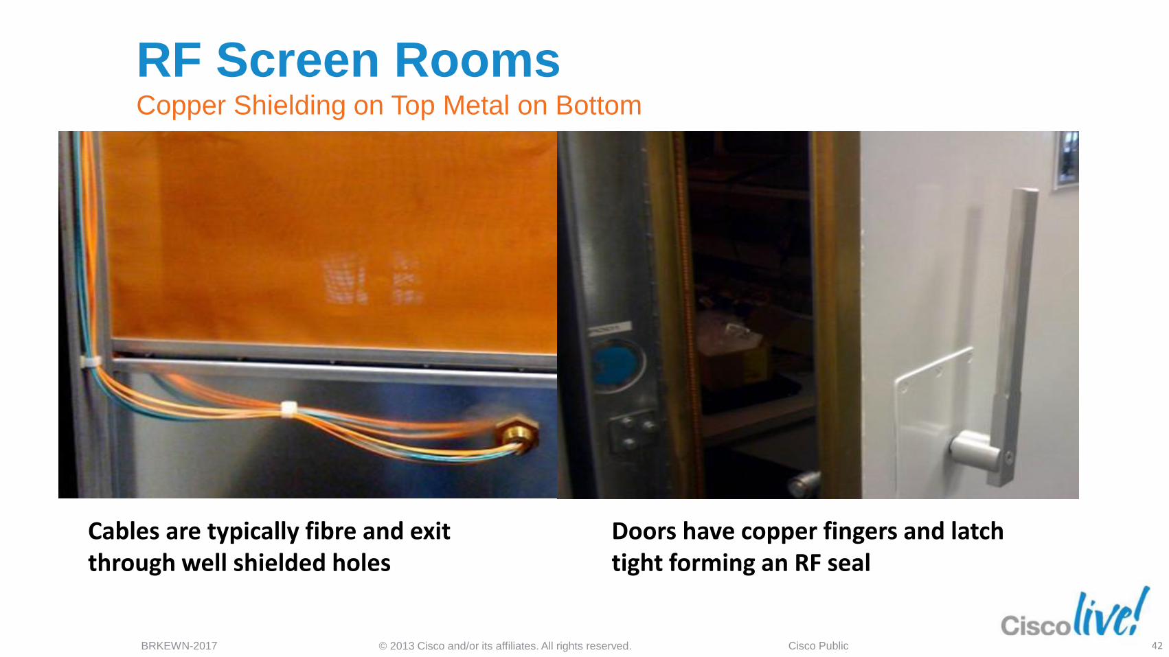
Cables are typically fibre and exit through well shielded holes
Doors have copper fingers and latch tight forming an RF seal
RF Screen Rooms Copper Shielding on Top Metal on Bottom
42
© 2013 Cisco and/or its affiliates. All rights reserved. BRKEWN-2017 Cisco Public
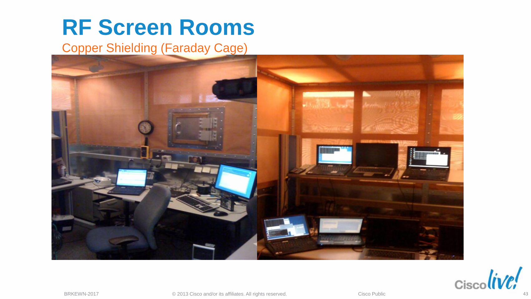
RF Screen Rooms Copper Shielding (Faraday Cage)
43
© 2013 Cisco and/or its affiliates. All rights reserved. BRKEWN-2017 Cisco Public
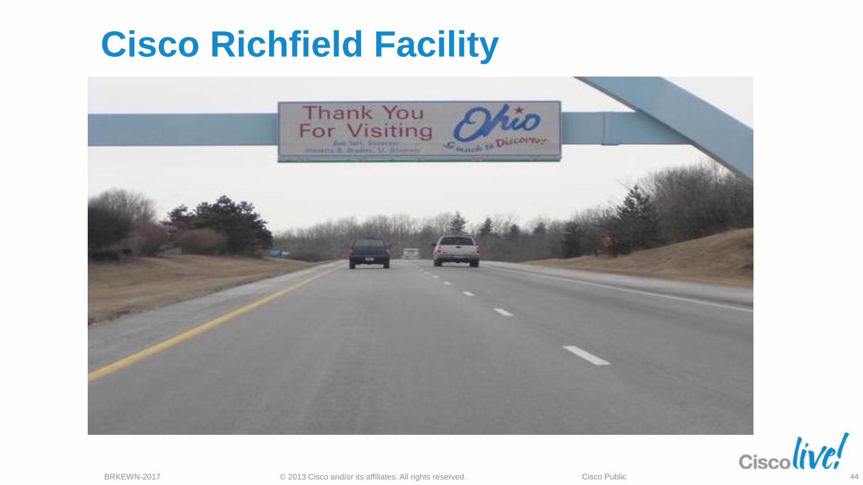
Cisco Richfield Facility
44
Understanding Multipath
Diversity and Beamforming
802.11n
© 2013 Cisco and/or its affiliates. All rights reserved. BRKEWN-2017 Cisco Public
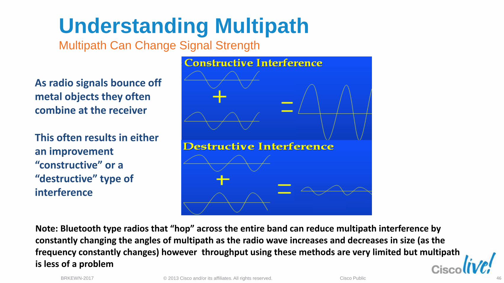
As radio signals bounce off metal objects they often combine at the receiver This often results in either an improvement “constructive” or a “destructive” type of interference
Note: Bluetooth type radios that “hop” across the entire band can reduce multipath interference by constantly changing the angles of multipath as the radio wave increases and decreases in size (as the frequency constantly changes) however throughput using these methods are very limited but multipath is less of a problem
Understanding Multipath Multipath Can Change Signal Strength
46
© 2013 Cisco and/or its affiliates. All rights reserved. BRKEWN-2017 Cisco Public
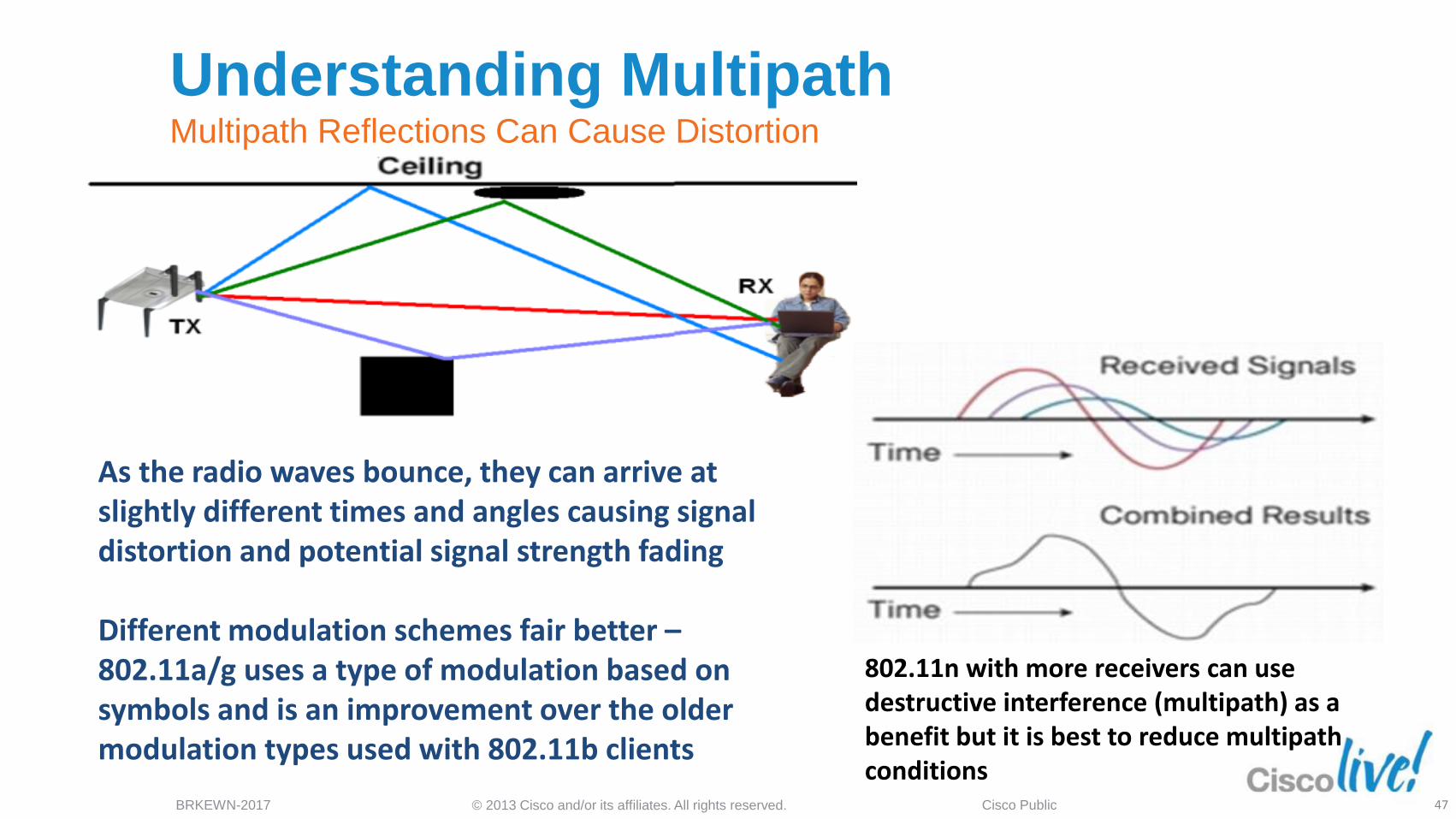
As the radio waves bounce, they can arrive at slightly different times and angles causing signal distortion and potential signal strength fading Different modulation schemes fair better – 802.11a/g uses a type of modulation based on symbols and is an improvement over the older modulation types used with 802.11b clients
802.11n with more receivers can use destructive interference (multipath) as a benefit but it is best to reduce multipath conditions
Understanding Multipath Multipath Reflections Can Cause Distortion
47
© 2013 Cisco and/or its affiliates. All rights reserved. BRKEWN-2017 Cisco Public
Understanding Diversity (SISO) 802.11a/b/g had just one radio per band diversity was limited
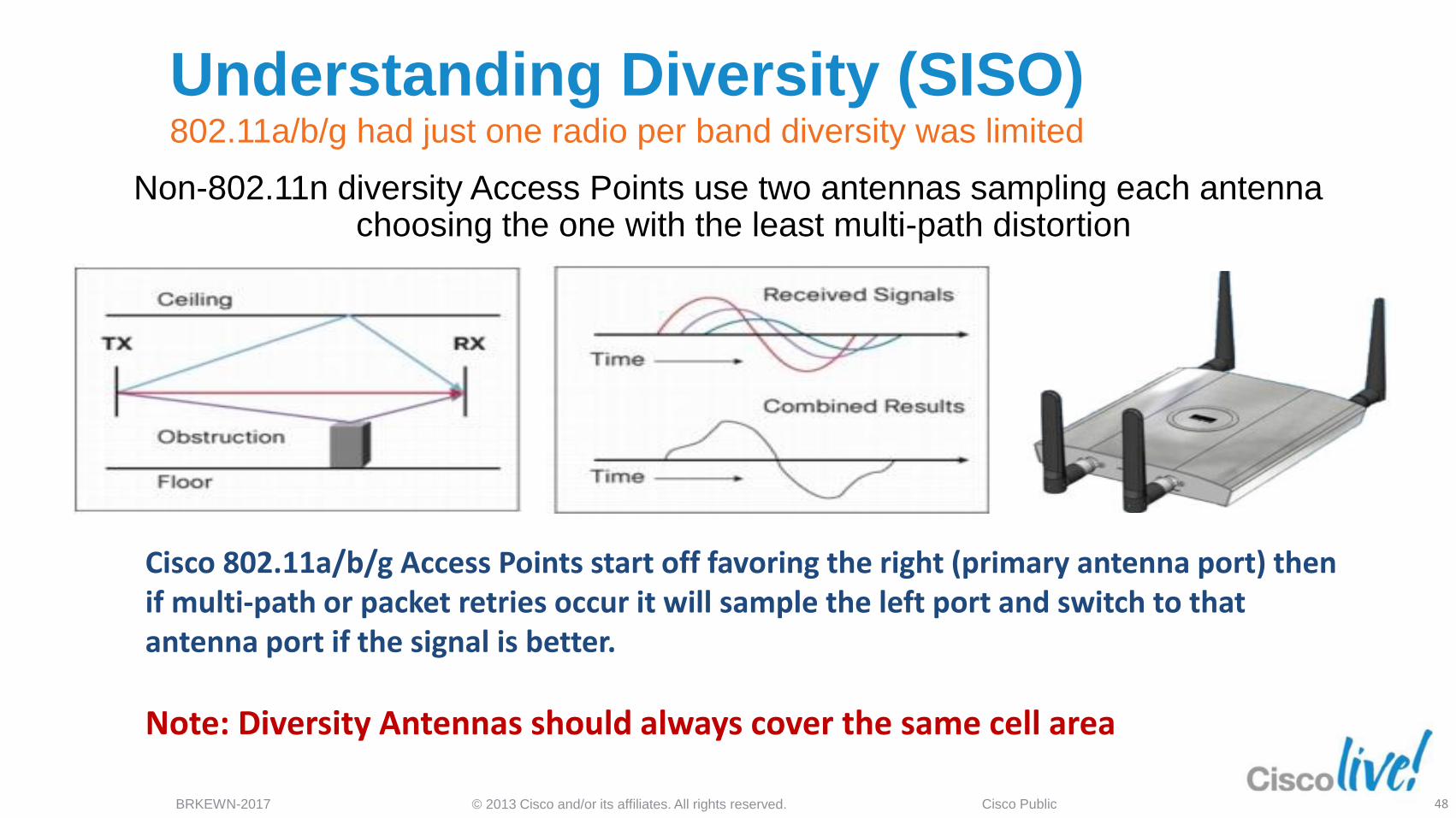
Non-802.11n diversity Access Points use two antennas sampling each antenna choosing the one with the least multi-path distortion
Cisco 802.11a/b/g Access Points start off favoring the right (primary antenna port) then if multi-path or packet retries occur it will sample the left port and switch to that antenna port if the signal is better.
Note: Diversity Antennas should always cover the same cell area
48
© 2013 Cisco and/or its affiliates. All rights reserved. BRKEWN-2017 Cisco Public
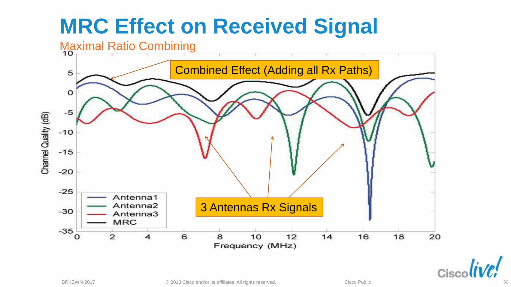
Understanding Diversity (MIMO) MRC Maximal Ratio Combining (Three Radios)
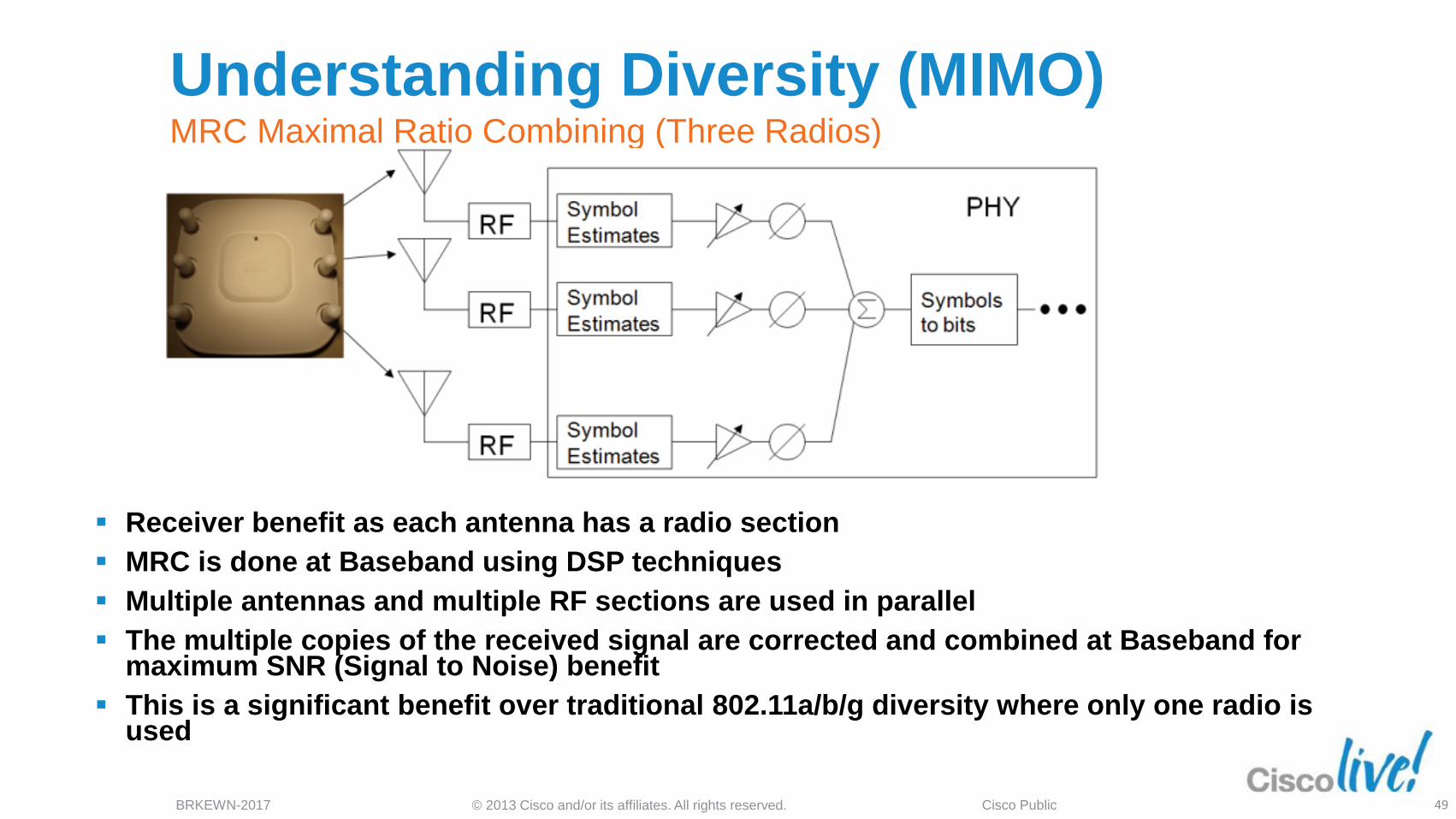
Receiver benefit as each antenna has a radio section
MRC is done at Baseband using DSP techniques
Multiple antennas and multiple RF sections are used in parallel
The multiple copies of the received signal are corrected and combined at Baseband for maximum SNR (Signal to Noise) benefit
This is a significant benefit over traditional 802.11a/b/g diversity where only one radio is used
49
© 2013 Cisco and/or its affiliates. All rights reserved. BRKEWN-2017 Cisco Public
3 Antennas Rx Signals
Combined Effect (Adding all Rx Paths)
MRC Effect on Received Signal Maximal Ratio Combining
50
© 2013 Cisco and/or its affiliates. All rights reserved. BRKEWN-2017 Cisco Public
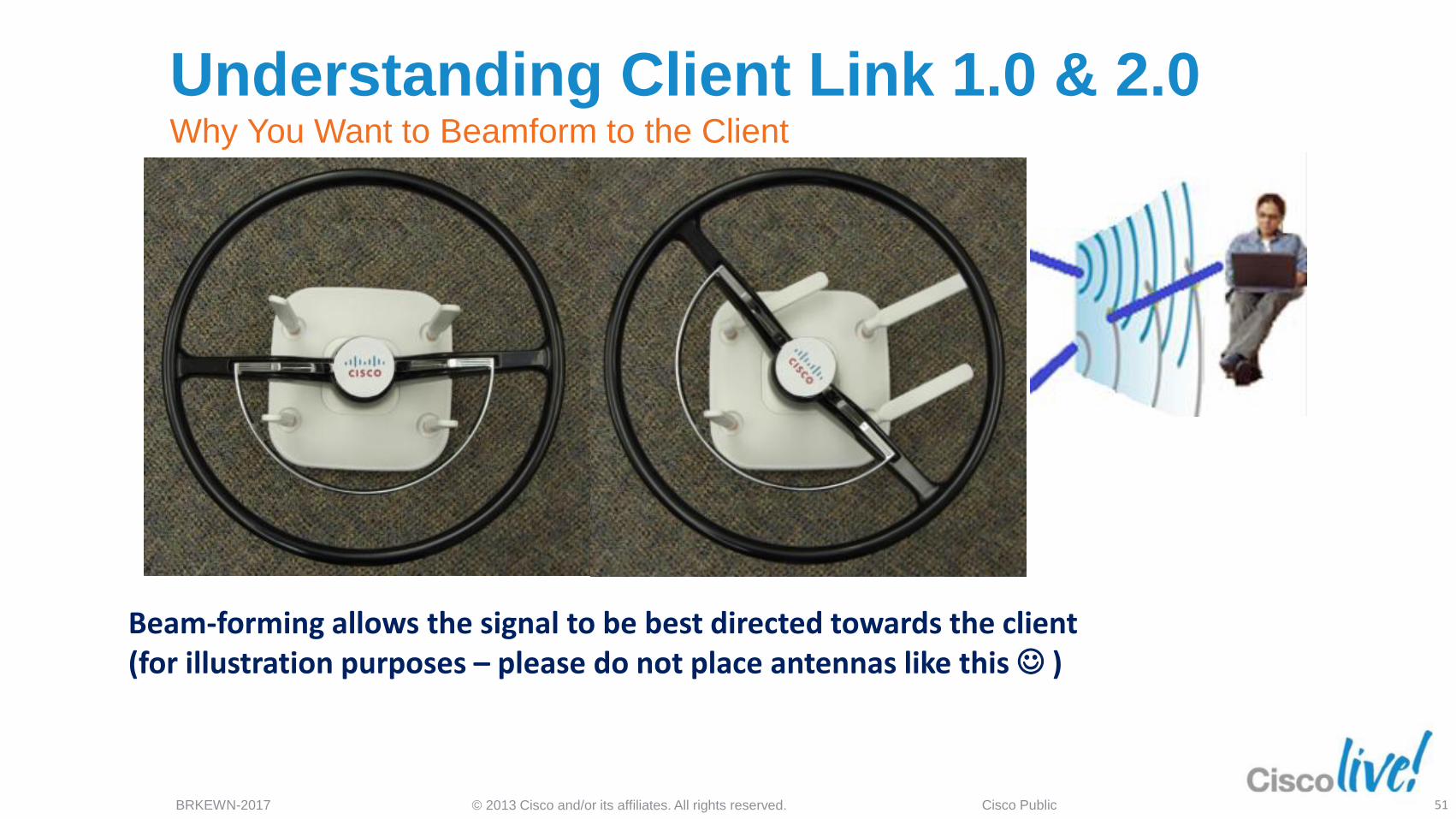
Beam-forming allows the signal to be best directed towards the client (for illustration purposes – please do not place antennas like this )
Understanding Client Link 1.0 & 2.0 Why You Want to Beamform to the Client
51
© 2013 Cisco and/or its affiliates. All rights reserved. BRKEWN-2017 Cisco Public
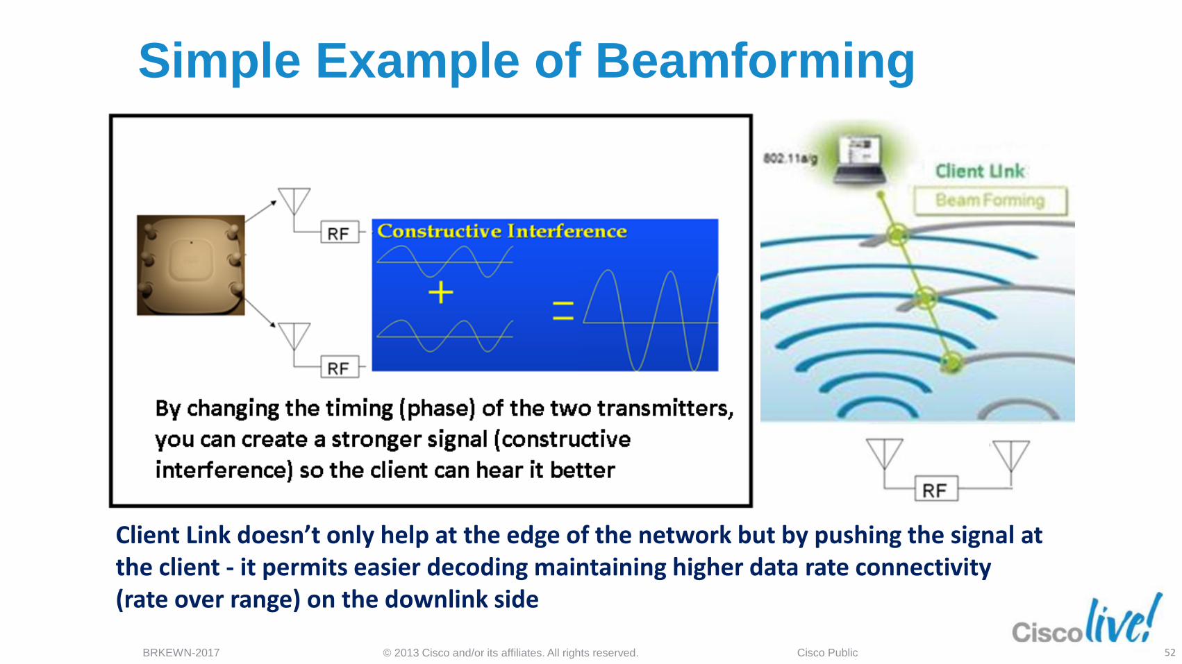
Client Link doesn’t only help at the edge of the network but by pushing the signal at the client - it permits easier decoding maintaining higher data rate connectivity (rate over range) on the downlink side
Simple Example of Beamforming
52
© 2013 Cisco and/or its affiliates. All rights reserved. BRKEWN-2017 Cisco Public
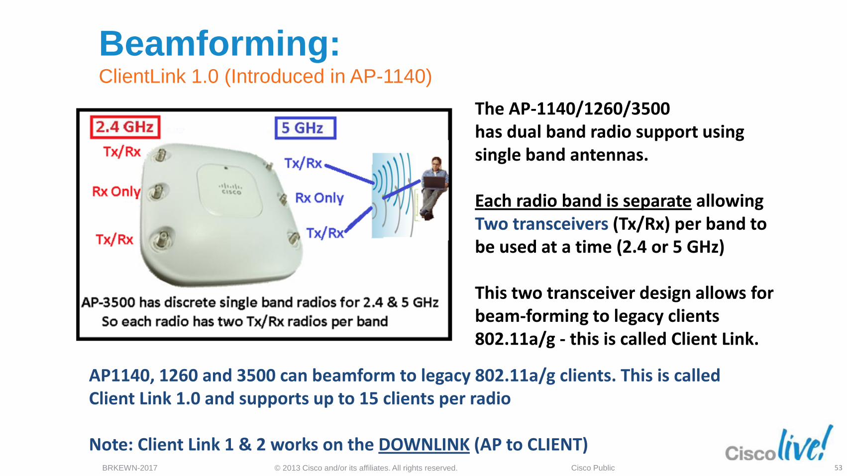
Beamforming: ClientLink 1.0 (Introduced in AP-1140)
The AP-1140/1260/3500 has dual band radio support using single band antennas. Each radio band is separate allowing Two transceivers (Tx/Rx) per band to be used at a time (2.4 or 5 GHz) This two transceiver design allows for beam-forming to legacy clients 802.11a/g - this is called Client Link.
AP1140, 1260 and 3500 can beamform to legacy 802.11a/g clients. This is called Client Link 1.0 and supports up to 15 clients per radio Note: Client Link 1 & 2 works on the DOWNLINK (AP to CLIENT)
53
© 2013 Cisco and/or its affiliates. All rights reserved. BRKEWN-2017 Cisco Public
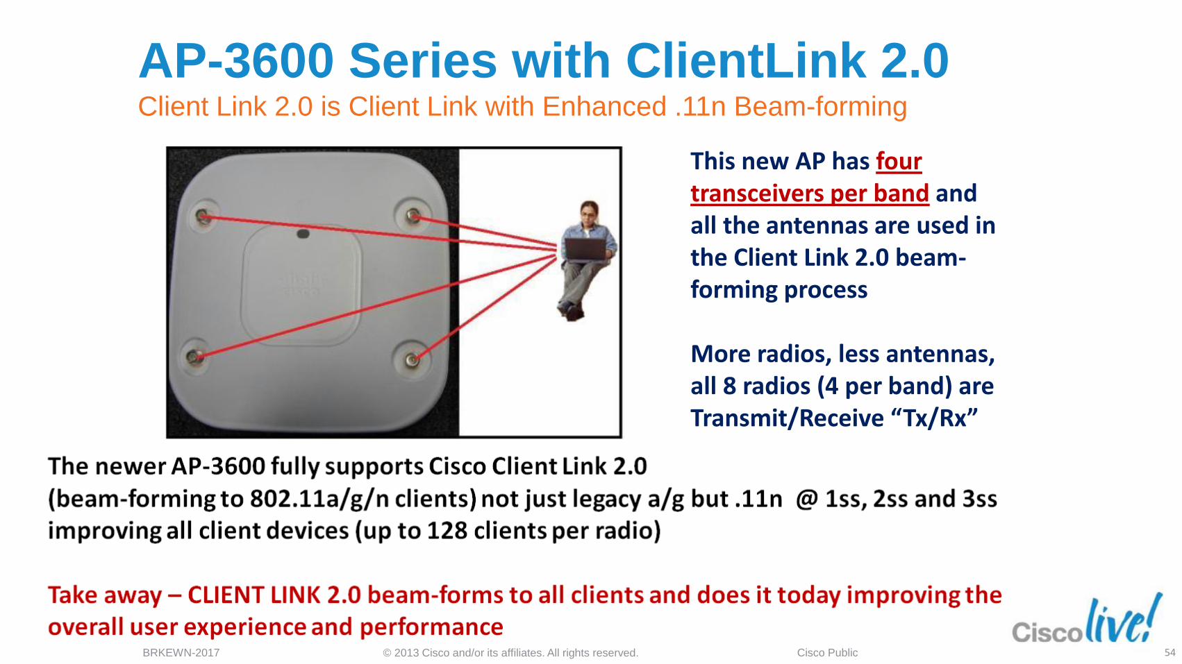
AP-3600 Series with ClientLink 2.0 Client Link 2.0 is Client Link with Enhanced .11n Beam-forming
This new AP has four transceivers per band and all the antennas are used in the Client Link 2.0 beam-forming process More radios, less antennas, all 8 radios (4 per band) are Transmit/Receive “Tx/Rx”
54
© 2013 Cisco and/or its affiliates. All rights reserved. BRKEWN-2017 Cisco Public
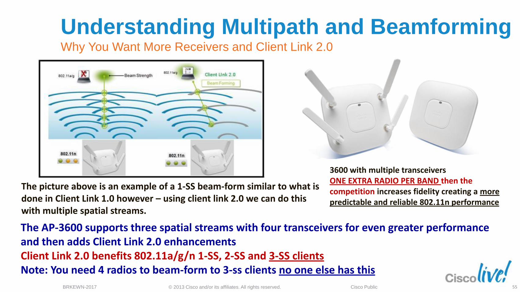
The picture above is an example of a 1-SS beam-form similar to what is done in Client Link 1.0 however – using client link 2.0 we can do this with multiple spatial streams.
3600 with multiple transceivers ONE EXTRA RADIO PER BAND then the competition increases fidelity creating a more predictable and reliable 802.11n performance
The AP-3600 supports three spatial streams with four transceivers for even greater performance and then adds Client Link 2.0 enhancements Client Link 2.0 benefits 802.11a/g/n 1-SS, 2-SS and 3-SS clients Note: You need 4 radios to beam-form to 3-ss clients no one else has this
Understanding Multipath and Beamforming Why You Want More Receivers and Client Link 2.0
55
© 2013 Cisco and/or its affiliates. All rights reserved. BRKEWN-2017 Cisco Public
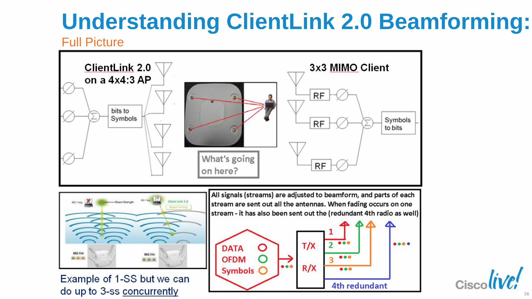
Understanding ClientLink 2.0 Beamforming: Full Picture
56
© 2013 Cisco and/or its affiliates. All rights reserved. BRKEWN-2017 Cisco Public
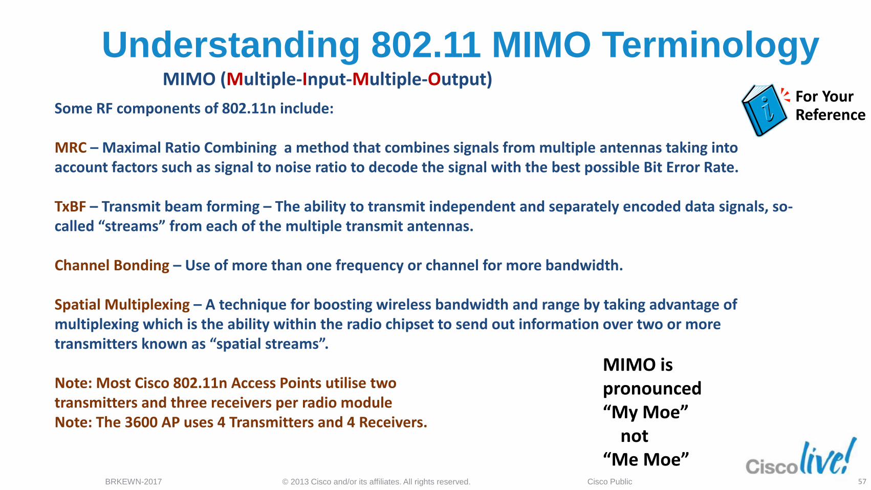
Understanding 802.11 MIMO Terminology MIMO (Multiple-Input-Multiple-Output)
Some RF components of 802.11n include: MRC – Maximal Ratio Combining a method that combines signals from multiple antennas taking into account factors such as signal to noise ratio to decode the signal with the best possible Bit Error Rate. TxBF – Transmit beam forming – The ability to transmit independent and separately encoded data signals, so-called “streams” from each of the multiple transmit antennas. Channel Bonding – Use of more than one frequency or channel for more bandwidth. Spatial Multiplexing – A technique for boosting wireless bandwidth and range by taking advantage of multiplexing which is the ability within the radio chipset to send out information over two or more transmitters known as “spatial streams”. Note: Most Cisco 802.11n Access Points utilise two transmitters and three receivers per radio module Note: The 3600 AP uses 4 Transmitters and 4 Receivers.
MIMO is pronounced “My Moe” not “Me Moe”
For Your Reference
57
© 2013 Cisco and/or its affiliates. All rights reserved. BRKEWN-2017 Cisco Public
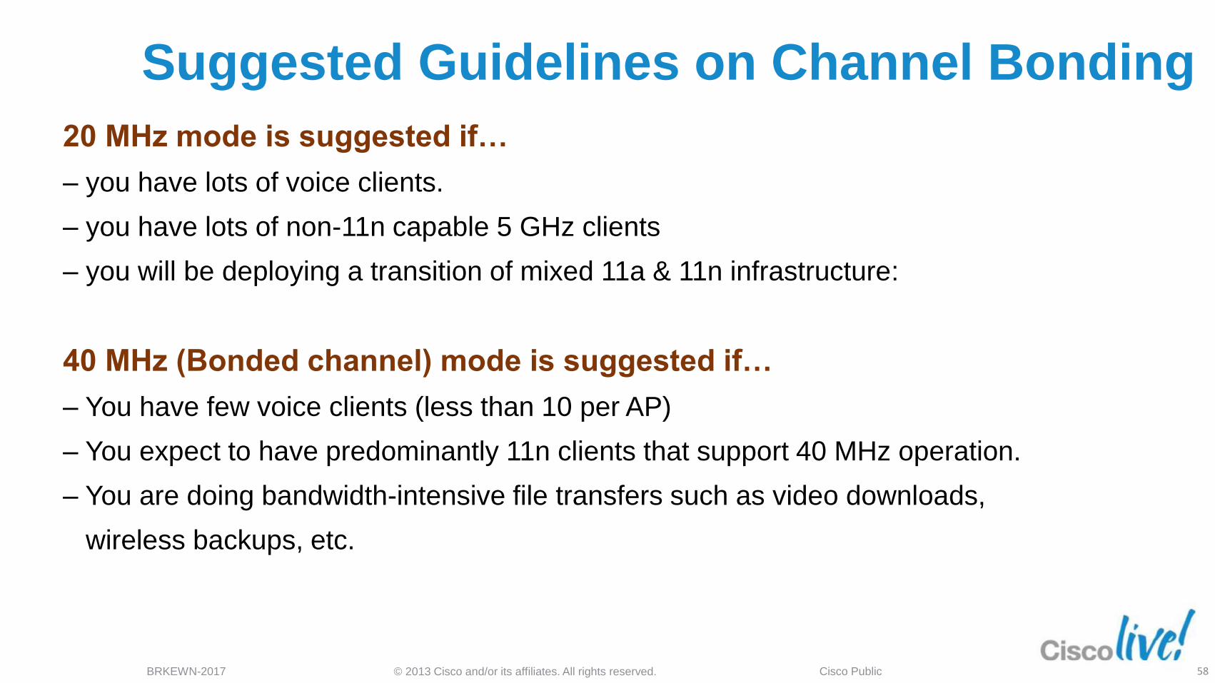
Suggested Guidelines on Channel Bonding
20 MHz mode is suggested if…
‒ you have lots of voice clients.
‒ you have lots of non-11n capable 5 GHz clients
‒ you will be deploying a transition of mixed 11a & 11n infrastructure:
40 MHz (Bonded channel) mode is suggested if…
‒ You have few voice clients (less than 10 per AP)
‒ You expect to have predominantly 11n clients that support 40 MHz operation.
‒ You are doing bandwidth-intensive file transfers such as video downloads,
wireless backups, etc.
58
© 2013 Cisco and/or its affiliates. All rights reserved. BRKEWN-2017 Cisco Public
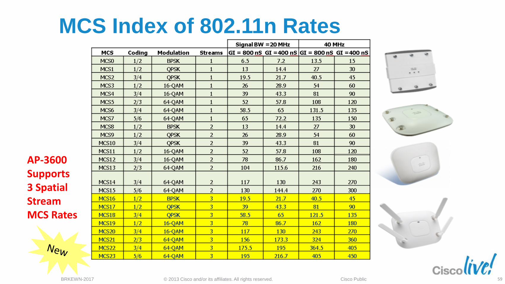
AP-3600 Supports 3 Spatial Stream MCS Rates
MCS Index of 802.11n Rates
59
© 2013 Cisco and/or its affiliates. All rights reserved. BRKEWN-2017 Cisco Public
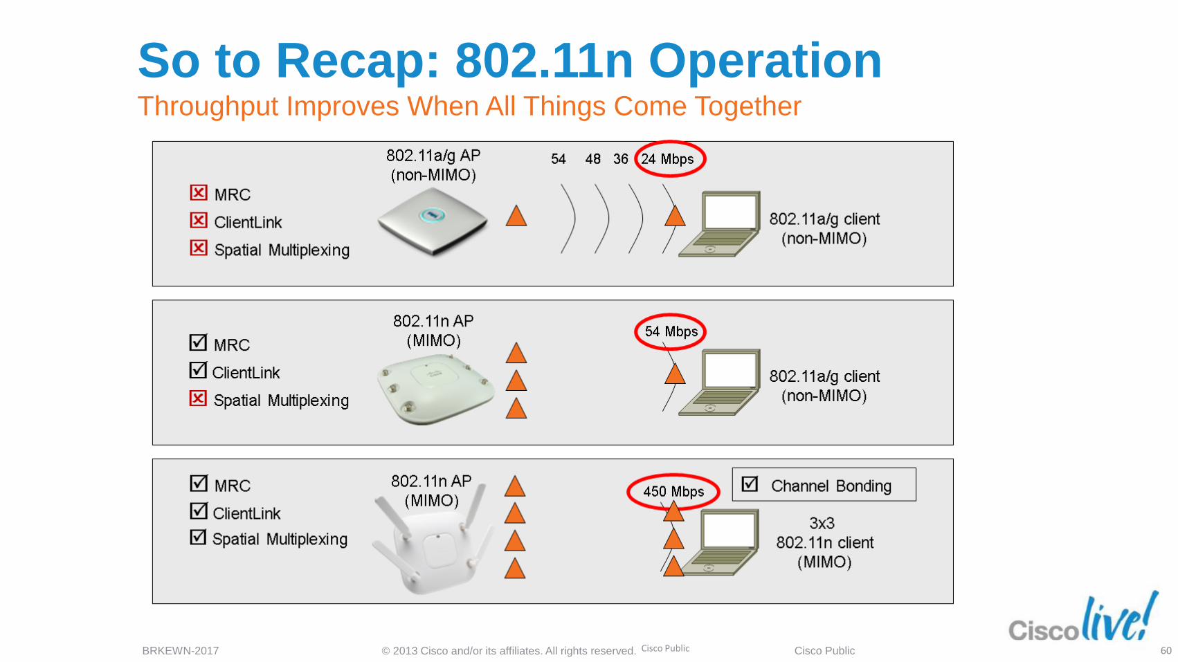
So to Recap: 802.11n Operation Throughput Improves When All Things Come Together
Cisco Public 60

Access Points and Features
© 2013 Cisco and/or its affiliates. All rights reserved. BRKEWN-2017 Cisco Public
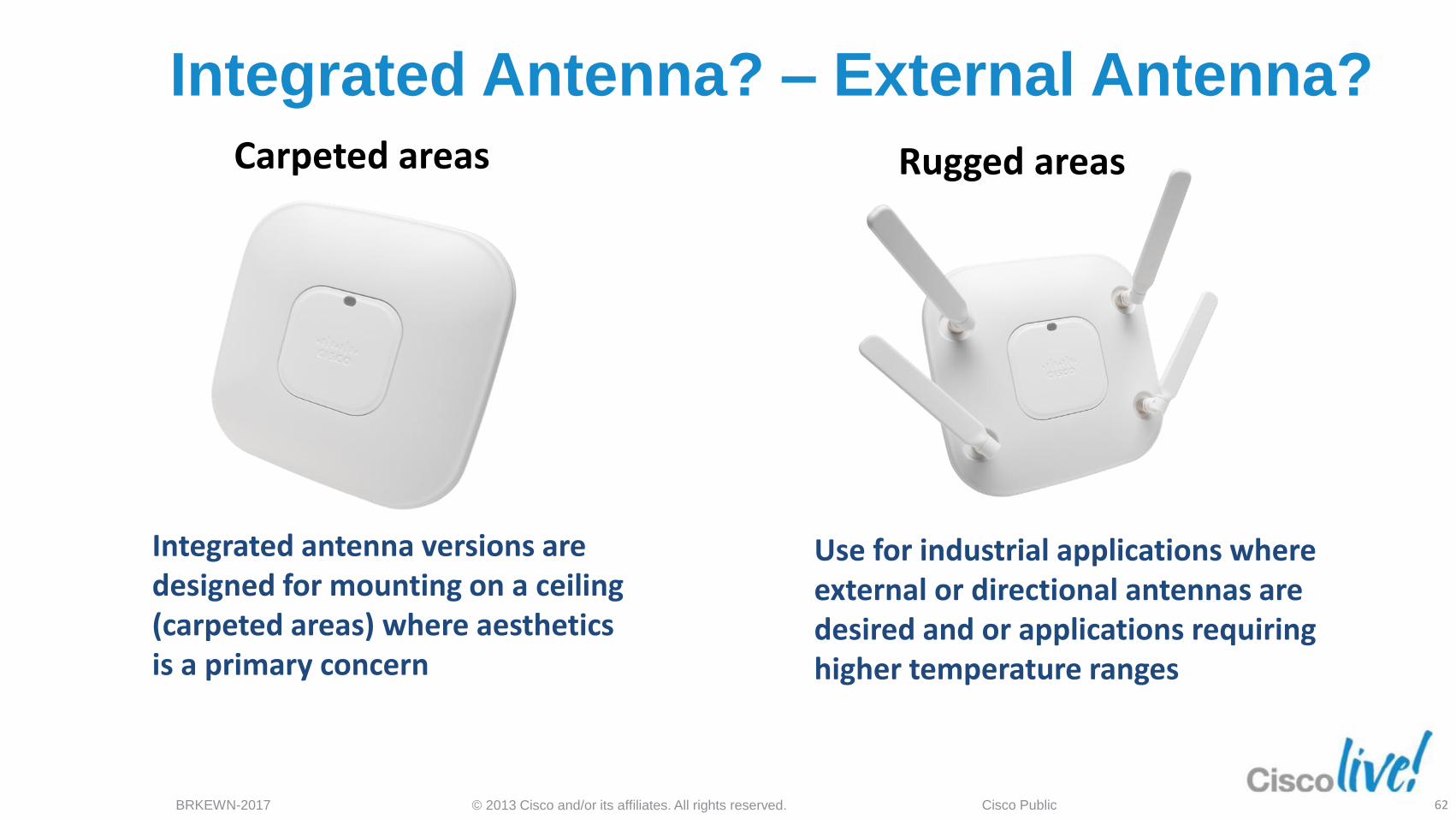
Integrated Antenna? – External Antenna?
Integrated antenna versions are designed for mounting on a ceiling (carpeted areas) where aesthetics is a primary concern
Use for industrial applications where external or directional antennas are desired and or applications requiring higher temperature ranges
Carpeted areas Rugged areas
62
© 2013 Cisco and/or its affiliates. All rights reserved. BRKEWN-2017 Cisco Public
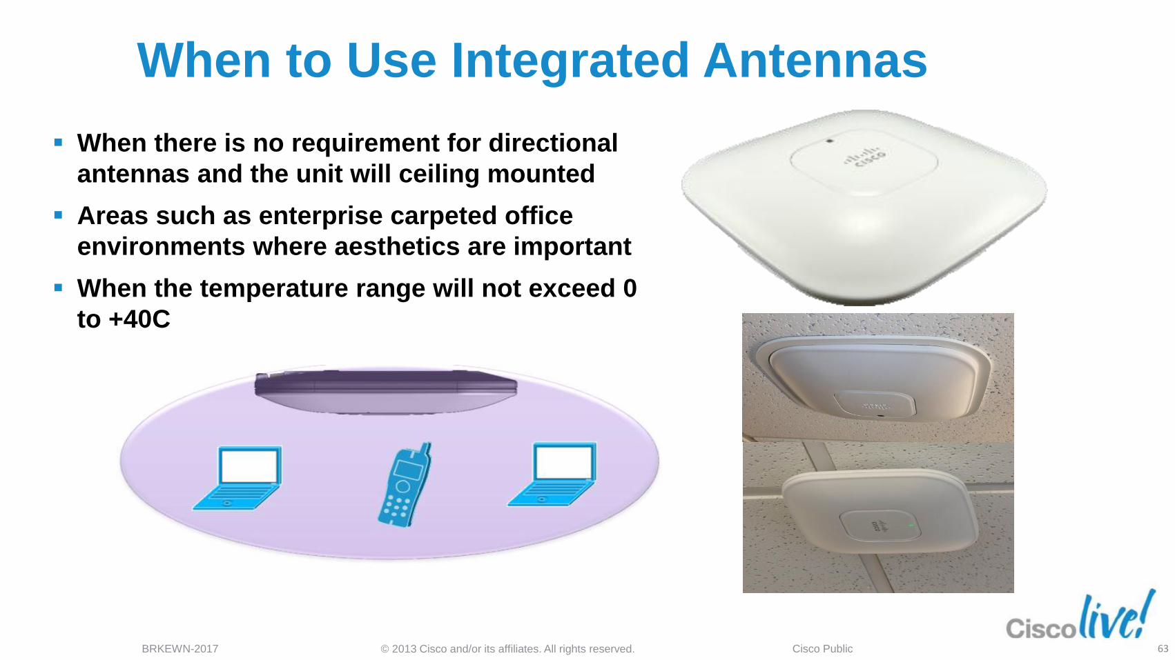
When to Use Integrated Antennas
When there is no requirement for directional
antennas and the unit will ceiling mounted
Areas such as enterprise carpeted office
environments where aesthetics are important
When the temperature range will not exceed 0
to +40C
63
© 2013 Cisco and/or its affiliates. All rights reserved. BRKEWN-2017 Cisco Public
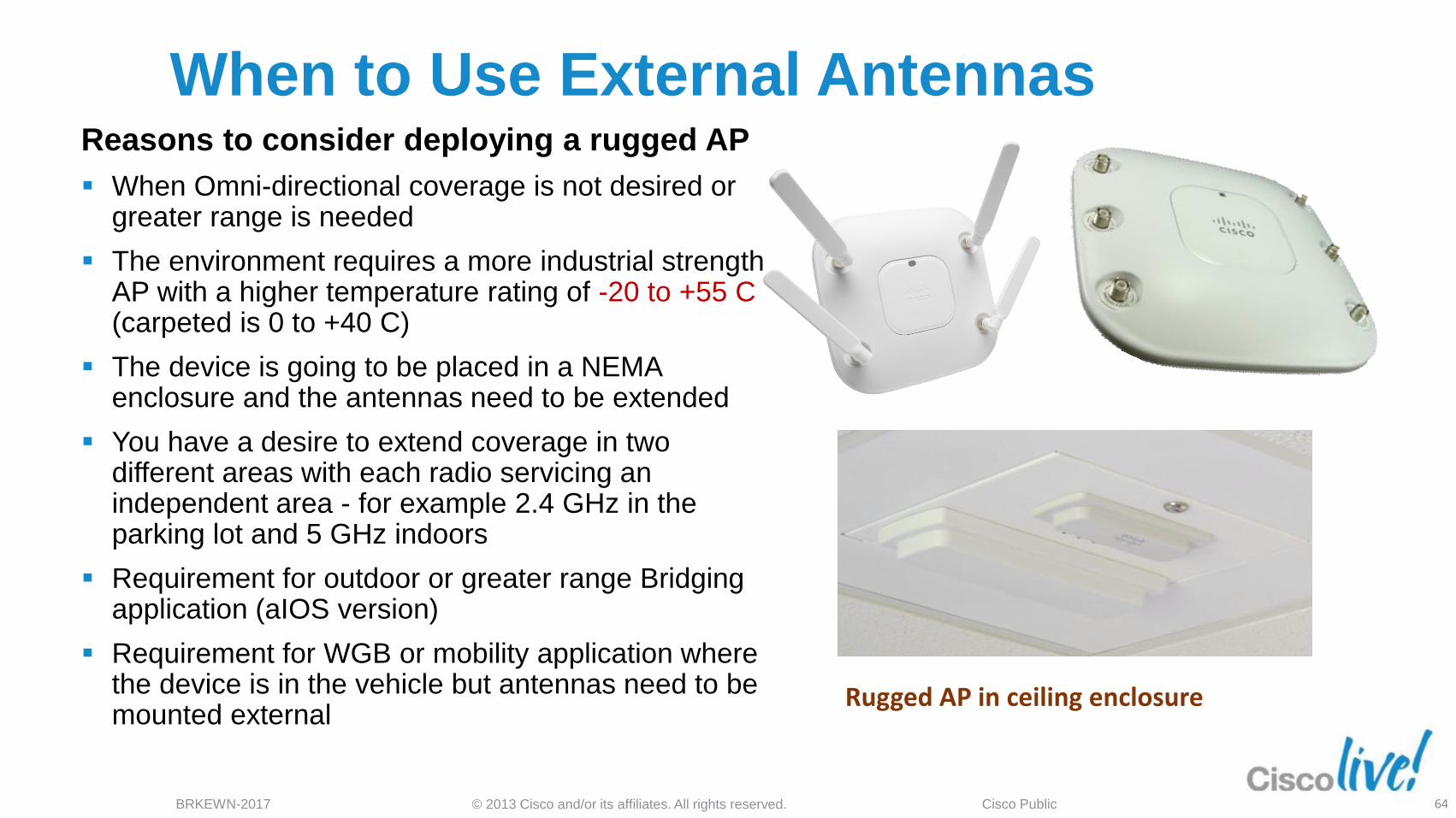
When to Use External Antennas Reasons to consider deploying a rugged AP
When Omni-directional coverage is not desired or greater range is needed
The environment requires a more industrial strength AP with a higher temperature rating of -20 to +55 C (carpeted is 0 to +40 C)
The device is going to be placed in a NEMA enclosure and the antennas need to be extended
You have a desire to extend coverage in two different areas with each radio servicing an independent area - for example 2.4 GHz in the parking lot and 5 GHz indoors
Requirement for outdoor or greater range Bridging application (aIOS version)
Requirement for WGB or mobility application where the device is in the vehicle but antennas need to be mounted external
Rugged AP in ceiling enclosure
64
© 2013 Cisco and/or its affiliates. All rights reserved. BRKEWN-2017 Cisco Public
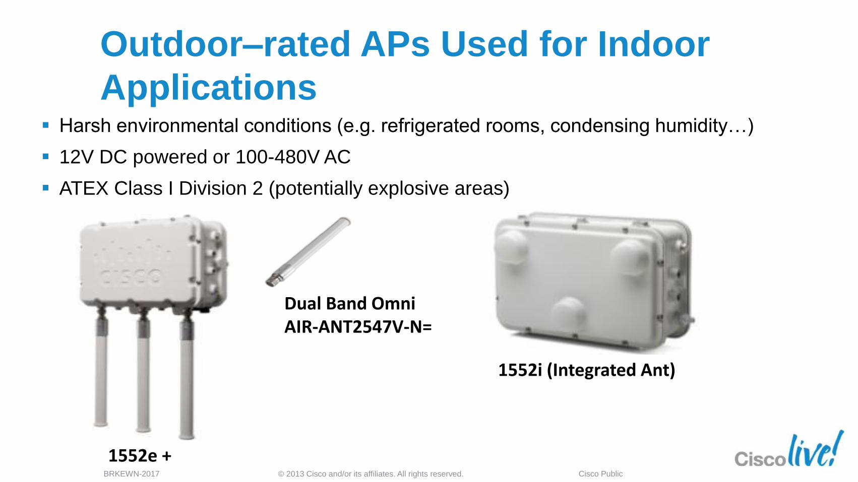
Outdoor–rated APs Used for Indoor
Applications Harsh environmental conditions (e.g. refrigerated rooms, condensing humidity…)
12V DC powered or 100-480V AC
ATEX Class I Division 2 (potentially explosive areas)
1552i (Integrated Ant)
Dual Band Omni AIR-ANT2547V-N=
1552e +
65
© 2013 Cisco and/or its affiliates. All rights reserved. BRKEWN-2017 Cisco Public
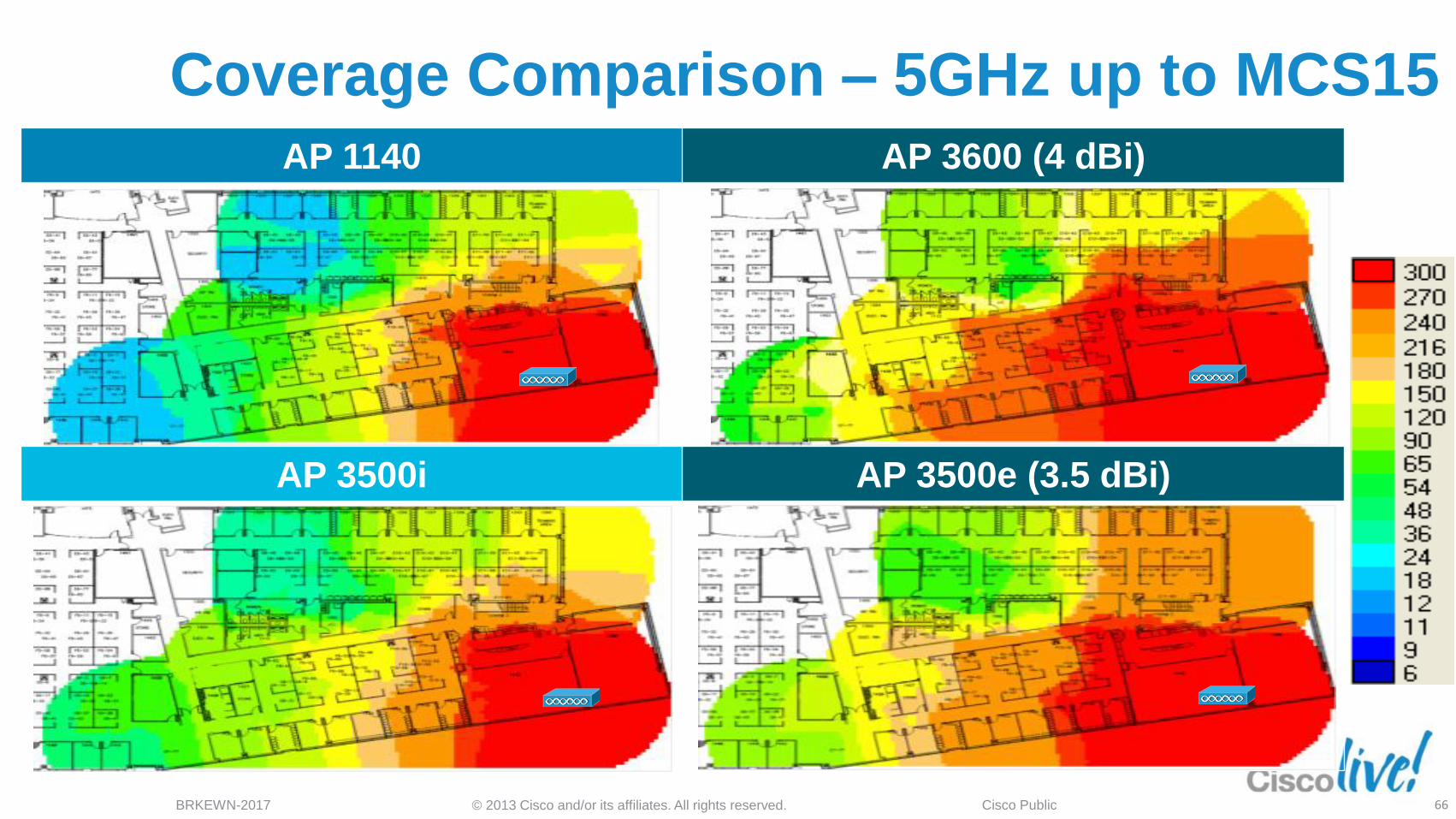
AP 1140 AP 3600 (4 dBi)
AP 3500i AP 3500e (3.5 dBi)
Coverage Comparison – 5GHz up to MCS15
66
Installation and Deployment
Considerations
© 2013 Cisco and/or its affiliates. All rights reserved. BRKEWN-2017 Cisco Public
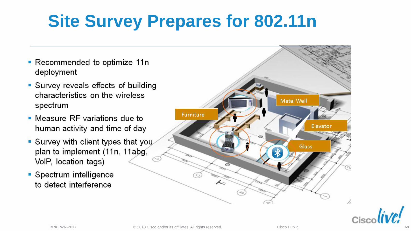
Site Survey Prepares for 802.11n
68
© 2013 Cisco and/or its affiliates. All rights reserved. BRKEWN-2017 Cisco Public
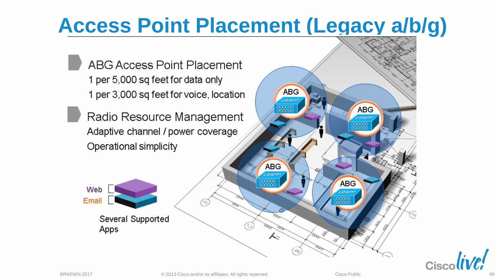
Access Point Placement (Legacy a/b/g)
69
© 2013 Cisco and/or its affiliates. All rights reserved. BRKEWN-2017 Cisco Public
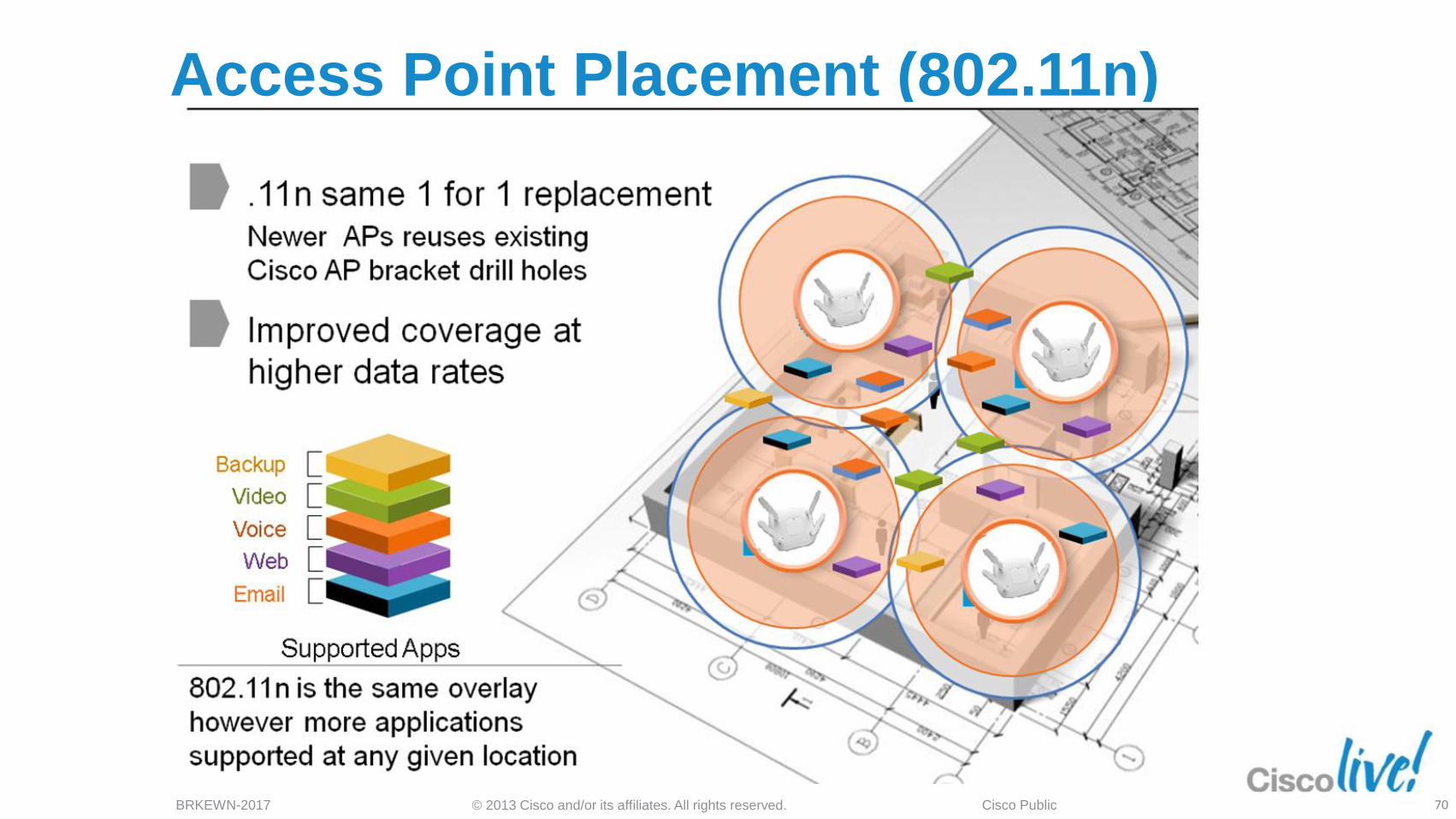
Access Point Placement (802.11n)
70
© 2013 Cisco and/or its affiliates. All rights reserved. BRKEWN-2017 Cisco Public
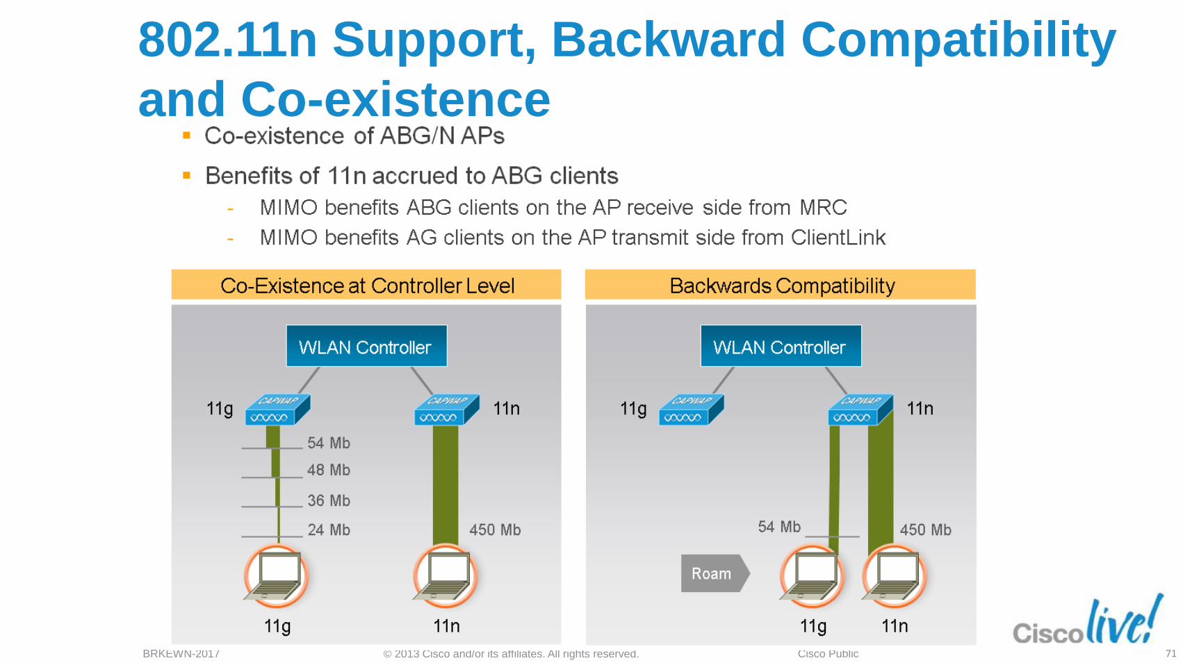
802.11n Support, Backward Compatibility
and Co-existence
71
© 2013 Cisco and/or its affiliates. All rights reserved. BRKEWN-2017 Cisco Public
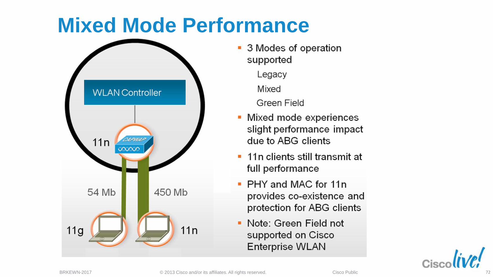
Mixed Mode Performance
72
© 2013 Cisco and/or its affiliates. All rights reserved. BRKEWN-2017 Cisco Public
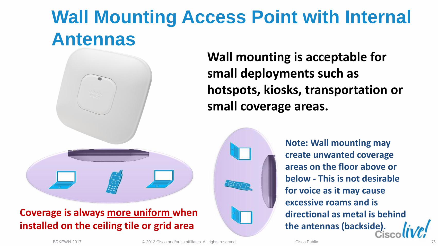
Wall Mounting Access Point with Internal
Antennas
Coverage is always more uniform when installed on the ceiling tile or grid area
Note: Wall mounting may create unwanted coverage areas on the floor above or below - This is not desirable for voice as it may cause excessive roams and is directional as metal is behind the antennas (backside).
Wall mounting is acceptable for small deployments such as hotspots, kiosks, transportation or small coverage areas.
73
© 2013 Cisco and/or its affiliates. All rights reserved. BRKEWN-2017 Cisco Public
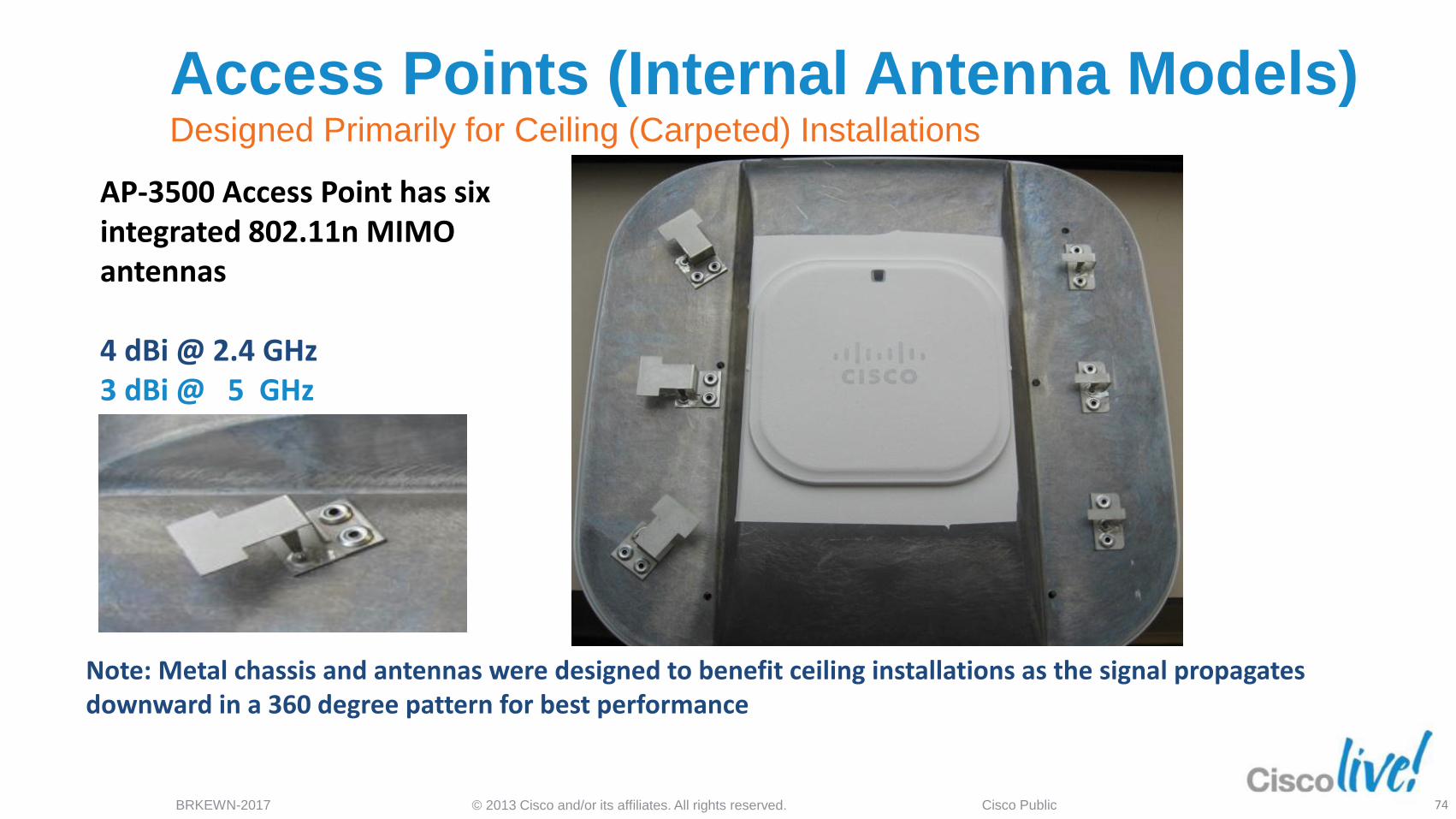
Access Points (Internal Antenna Models) Designed Primarily for Ceiling (Carpeted) Installations
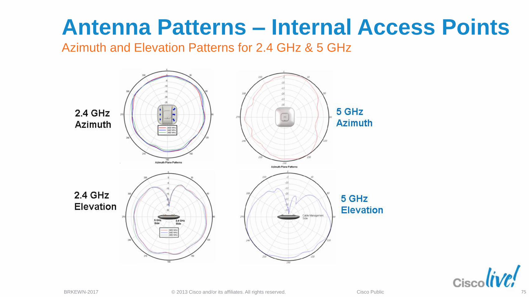
AP-3500 Access Point has six integrated 802.11n MIMO antennas 4 dBi @ 2.4 GHz 3 dBi @ 5 GHz
Note: Metal chassis and antennas were designed to benefit ceiling installations as the signal propagates downward in a 360 degree pattern for best performance
74
© 2013 Cisco and/or its affiliates. All rights reserved. BRKEWN-2017 Cisco Public
Antenna Patterns – Internal Access Points Azimuth and Elevation Patterns for 2.4 GHz & 5 GHz
75
© 2013 Cisco and/or its affiliates. All rights reserved. BRKEWN-2017 Cisco Public
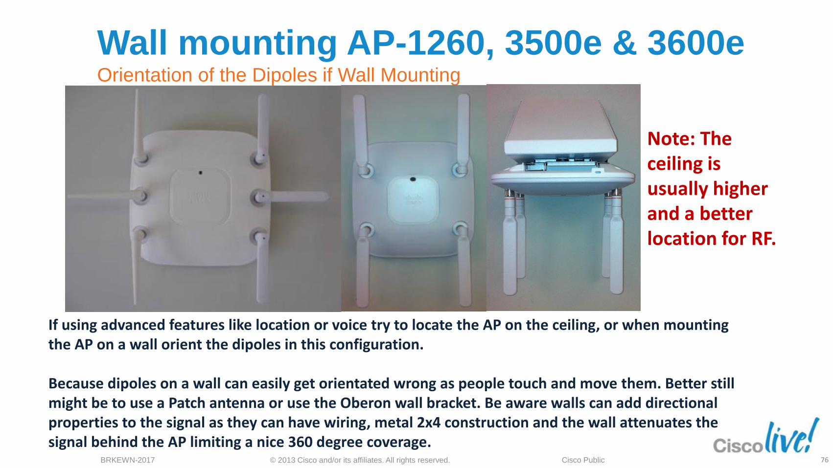
Wall mounting AP-1260, 3500e & 3600e Orientation of the Dipoles if Wall Mounting
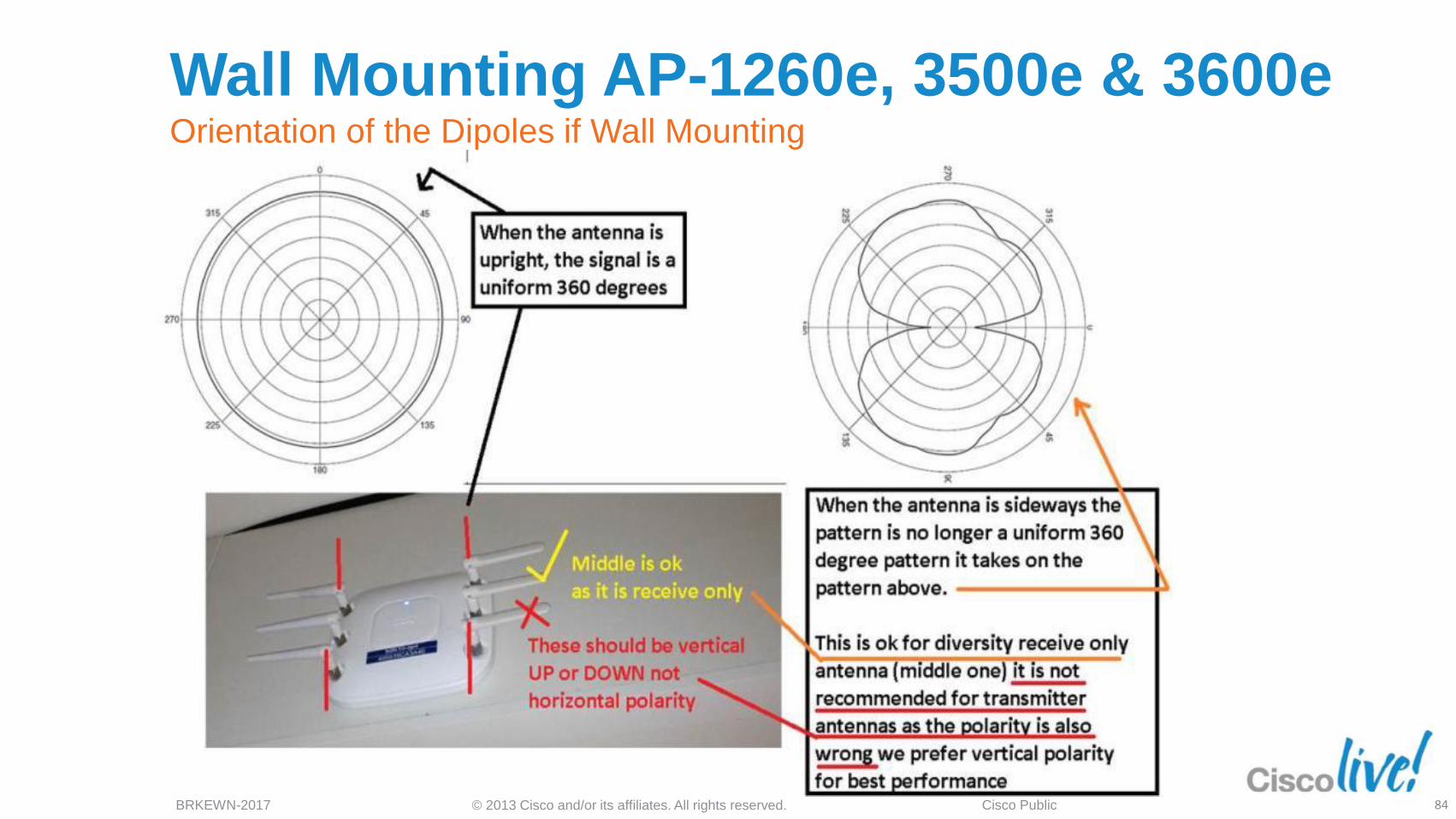
If using advanced features like location or voice try to locate the AP on the ceiling, or when mounting the AP on a wall orient the dipoles in this configuration. Because dipoles on a wall can easily get orientated wrong as people touch and move them. Better still might be to use a Patch antenna or use the Oberon wall bracket. Be aware walls can add directional properties to the signal as they can have wiring, metal 2x4 construction and the wall attenuates the signal behind the AP limiting a nice 360 degree coverage.
Note: The ceiling is usually higher and a better location for RF.
76
© 2013 Cisco and/or its affiliates. All rights reserved. BRKEWN-2017 Cisco Public
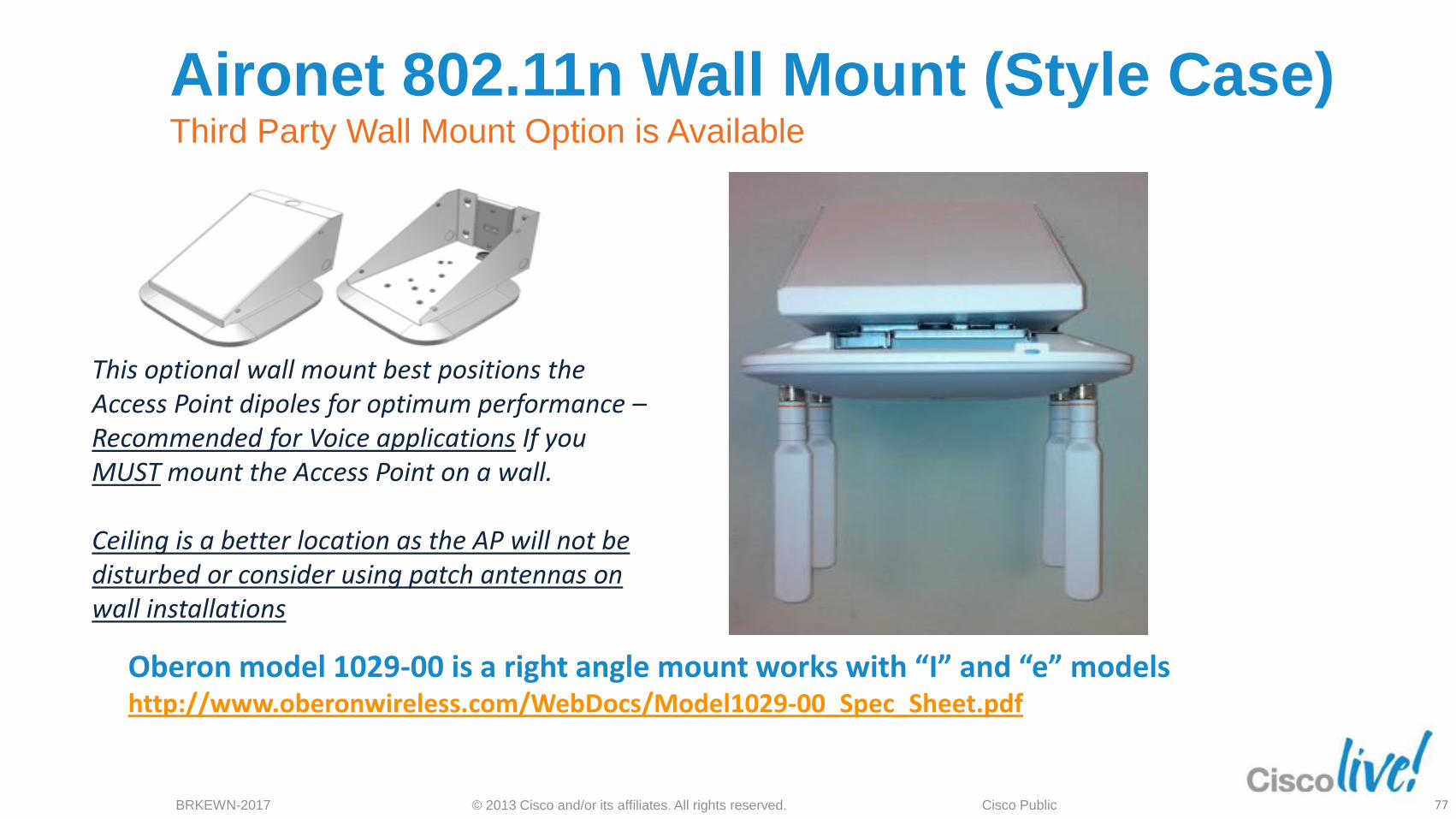
Aironet 802.11n Wall Mount (Style Case) Third Party Wall Mount Option is Available
Oberon model 1029-00 is a right angle mount works with “I” and “e” models http://www.oberonwireless.com/WebDocs/Model1029-00_Spec_Sheet.pdf
This optional wall mount best positions the Access Point dipoles for optimum performance – Recommended for Voice applications If you MUST mount the Access Point on a wall. Ceiling is a better location as the AP will not be disturbed or consider using patch antennas on wall installations
77
© 2013 Cisco and/or its affiliates. All rights reserved. BRKEWN-2017 Cisco Public
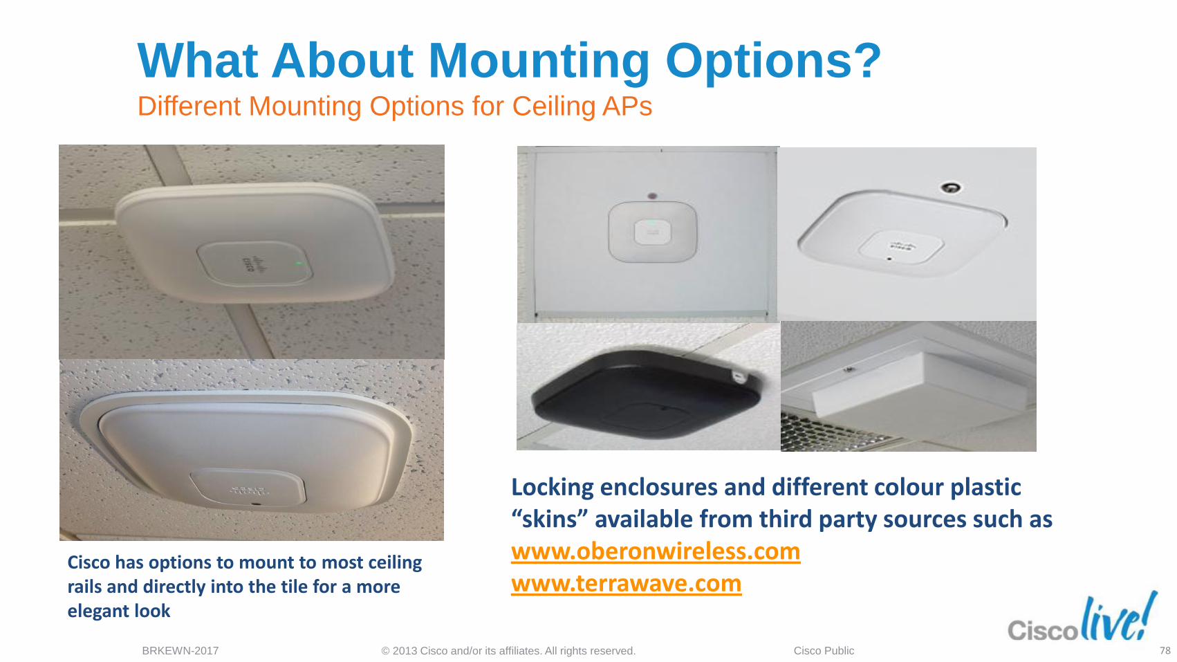
What About Mounting Options? Different Mounting Options for Ceiling APs
Cisco has options to mount to most ceiling rails and directly into the tile for a more elegant look
Locking enclosures and different colour plastic “skins” available from third party sources such as www.oberonwireless.com www.terrawave.com
78
© 2013 Cisco and/or its affiliates. All rights reserved. BRKEWN-2017 Cisco Public
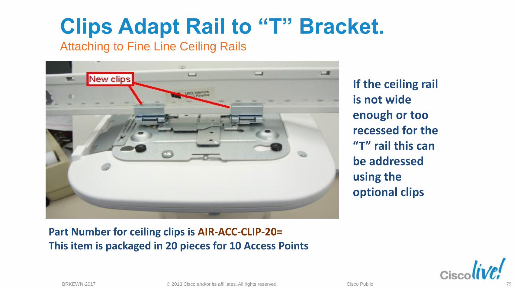
Clips Adapt Rail to “T” Bracket. Attaching to Fine Line Ceiling Rails
If the ceiling rail is not wide enough or too recessed for the “T” rail this can be addressed using the optional clips
Part Number for ceiling clips is AIR-ACC-CLIP-20= This item is packaged in 20 pieces for 10 Access Points
79
© 2013 Cisco and/or its affiliates. All rights reserved. BRKEWN-2017 Cisco Public
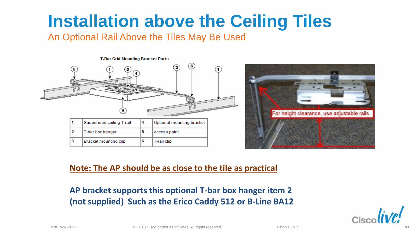
Installation above the Ceiling Tiles An Optional Rail Above the Tiles May Be Used
Note: The AP should be as close to the tile as practical AP bracket supports this optional T-bar box hanger item 2 (not supplied) Such as the Erico Caddy 512 or B-Line BA12
80
© 2013 Cisco and/or its affiliates. All rights reserved. BRKEWN-2017 Cisco Public
AP Placement Above False Ceiling Tiles
Areas
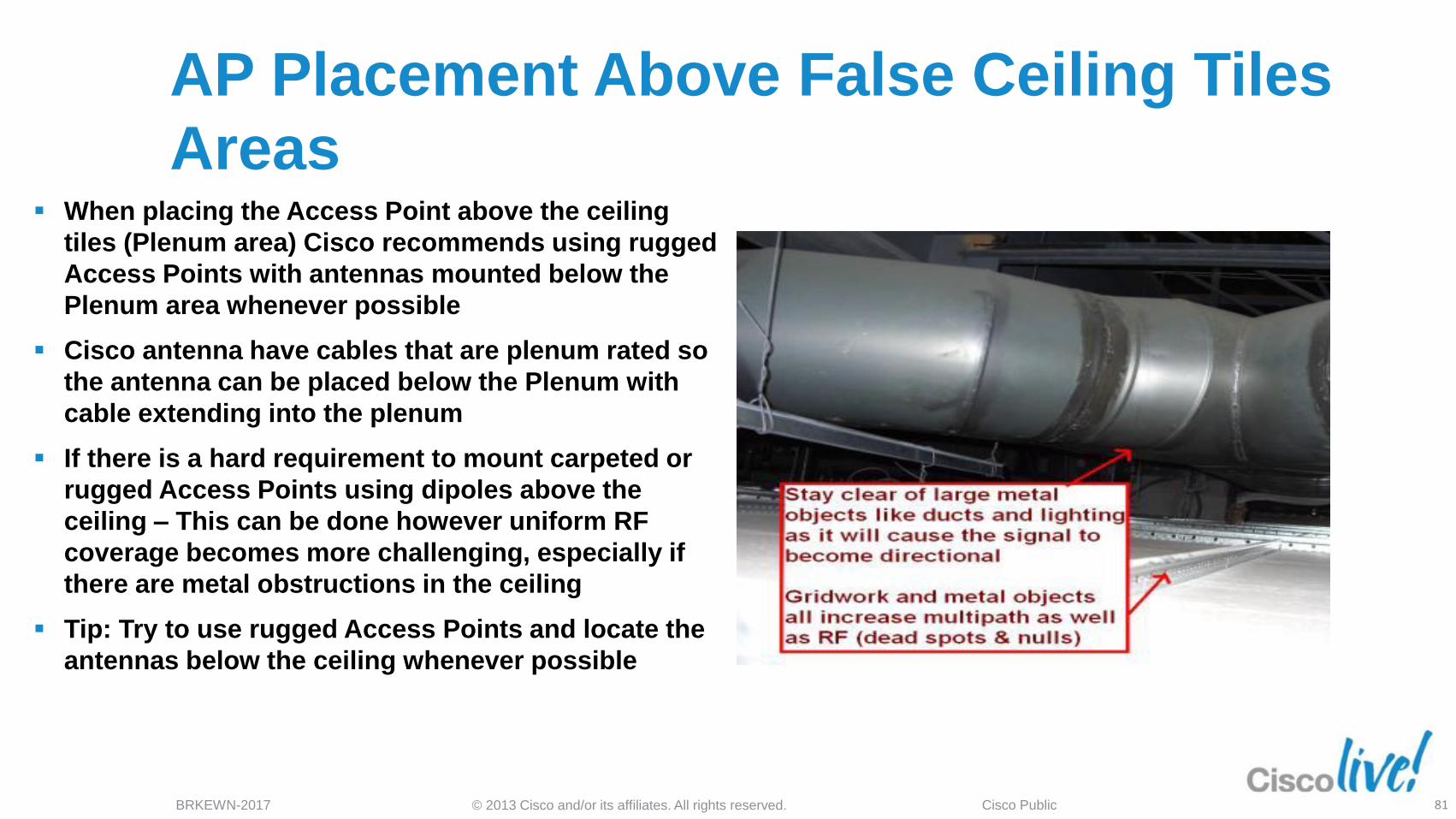
When placing the Access Point above the ceiling
tiles (Plenum area) Cisco recommends using rugged
Access Points with antennas mounted below the
Plenum area whenever possible
Cisco antenna have cables that are plenum rated so
the antenna can be placed below the Plenum with
cable extending into the plenum
If there is a hard requirement to mount carpeted or
rugged Access Points using dipoles above the
ceiling – This can be done however uniform RF
coverage becomes more challenging, especially if
there are metal obstructions in the ceiling
Tip: Try to use rugged Access Points and locate the
antennas below the ceiling whenever possible
81
© 2013 Cisco and/or its affiliates. All rights reserved. BRKEWN-2017 Cisco Public
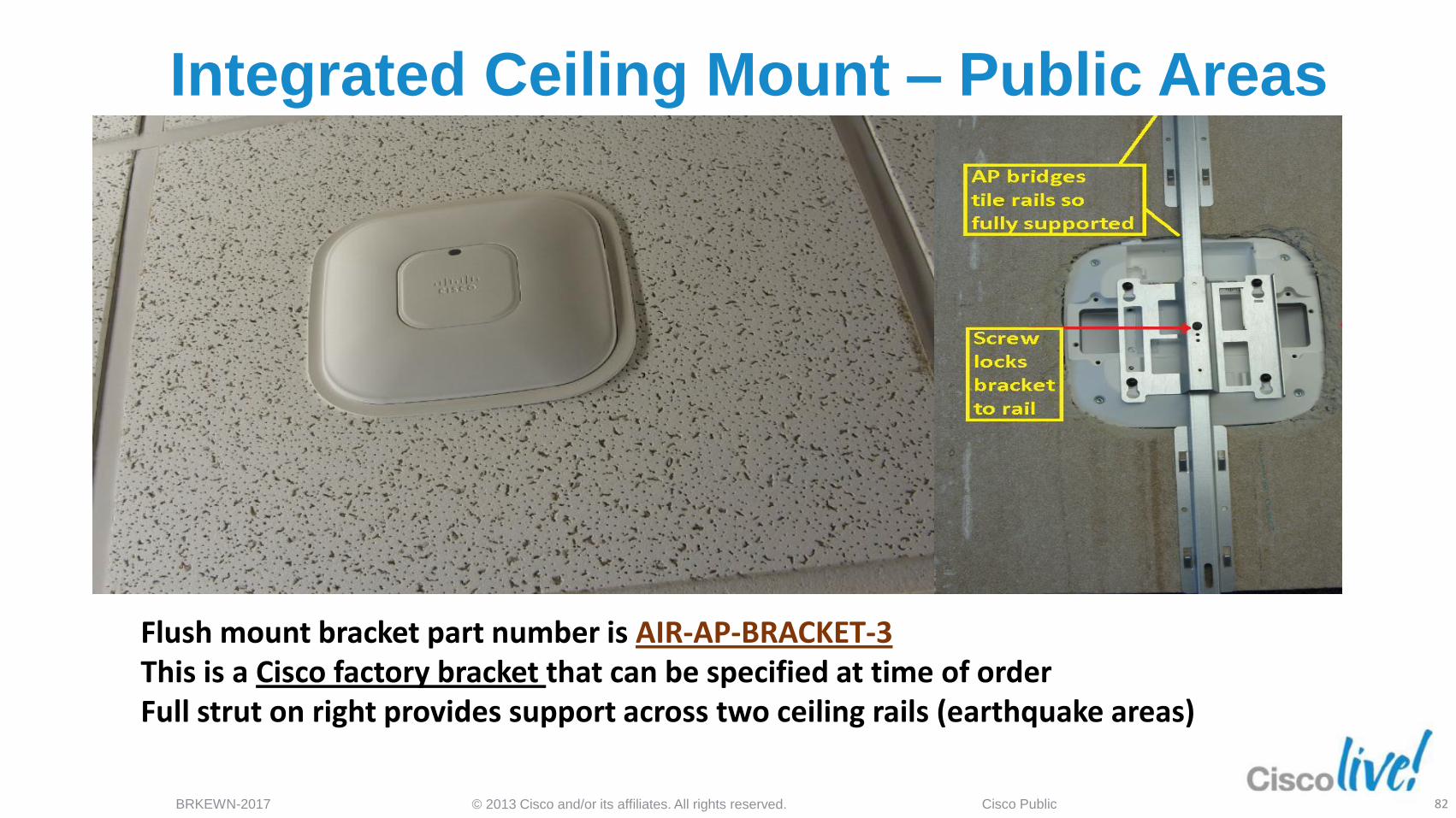
Integrated Ceiling Mount – Public Areas
Flush mount bracket part number is AIR-AP-BRACKET-3 This is a Cisco factory bracket that can be specified at time of order Full strut on right provides support across two ceiling rails (earthquake areas)
82
© 2013 Cisco and/or its affiliates. All rights reserved. BRKEWN-2017 Cisco Public
Antenna Placement Considerations
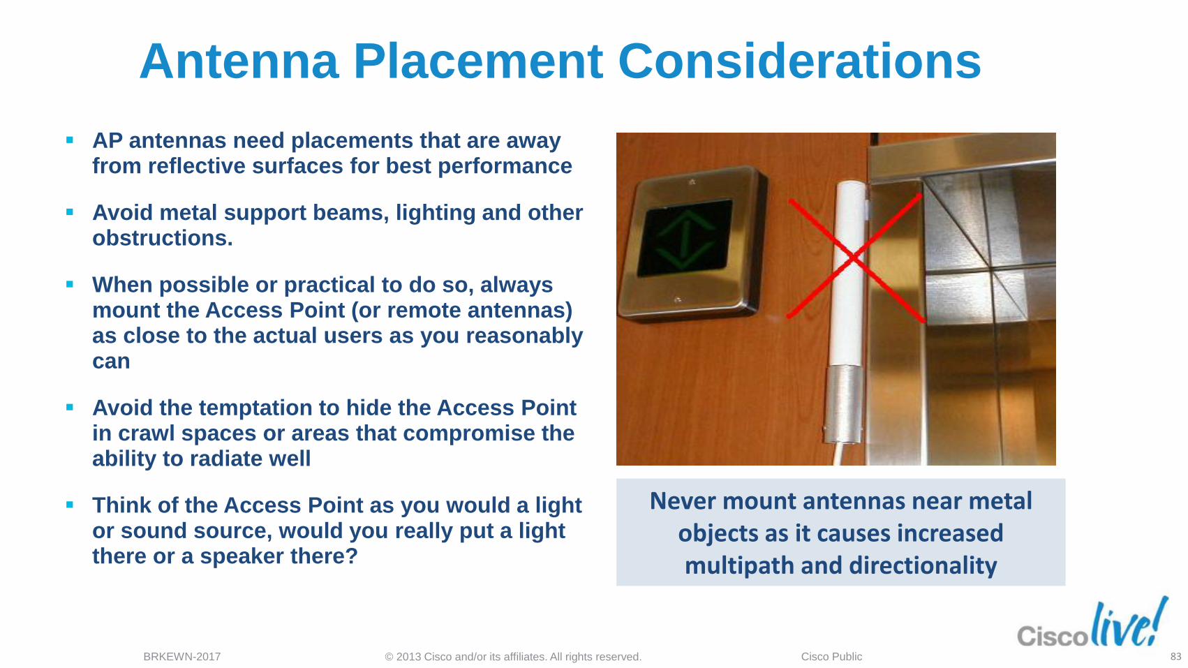
Never mount antennas near metal objects as it causes increased multipath and directionality
AP antennas need placements that are away from reflective surfaces for best performance
Avoid metal support beams, lighting and other obstructions.
When possible or practical to do so, always mount the Access Point (or remote antennas) as close to the actual users as you reasonably can
Avoid the temptation to hide the Access Point in crawl spaces or areas that compromise the ability to radiate well
Think of the Access Point as you would a light or sound source, would you really put a light there or a speaker there?
83
© 2013 Cisco and/or its affiliates. All rights reserved. BRKEWN-2017 Cisco Public
Wall Mounting AP-1260e, 3500e & 3600e Orientation of the Dipoles if Wall Mounting
84
© 2013 Cisco and/or its affiliates. All rights reserved. BRKEWN-2017 Cisco Public
Wall Mounting AP-1260e, 3500e & 3600e Orientation of the Dipoles if Wall Mounting
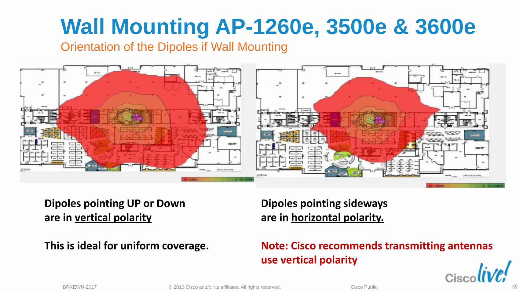
Dipoles pointing UP or Down are in vertical polarity This is ideal for uniform coverage.
Dipoles pointing sideways are in horizontal polarity. Note: Cisco recommends transmitting antennas use vertical polarity
85

Installations that went wrong…
© 2013 Cisco and/or its affiliates. All rights reserved. BRKEWN-2017 Cisco Public
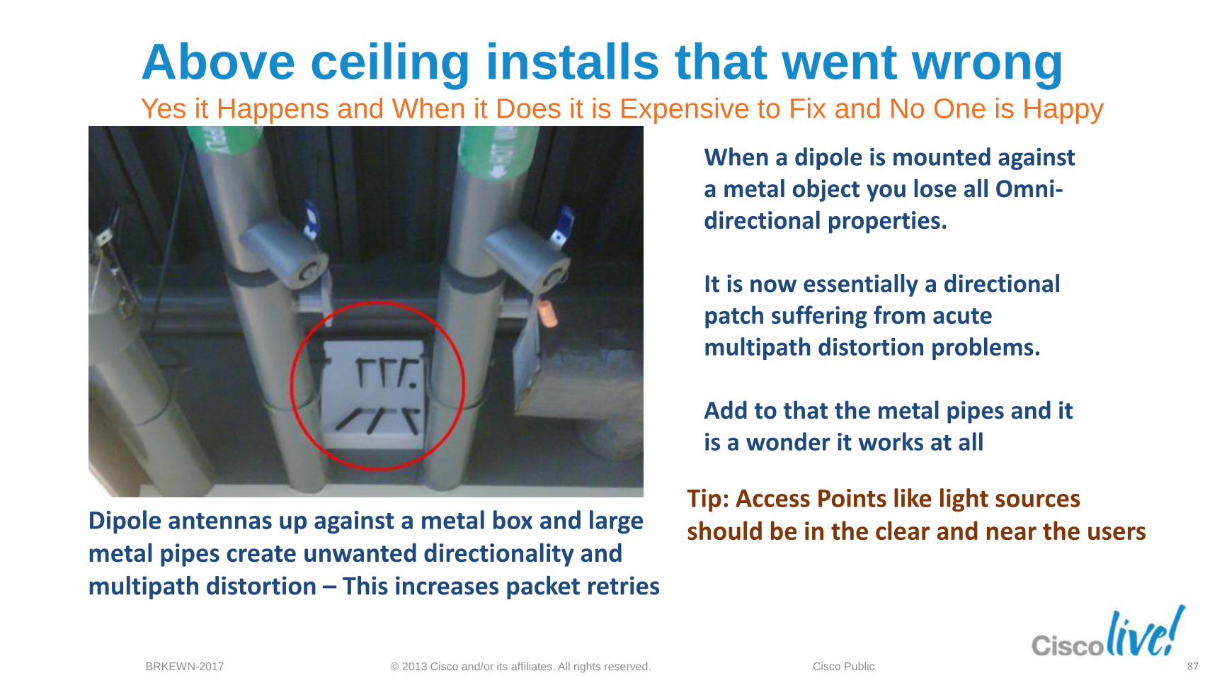
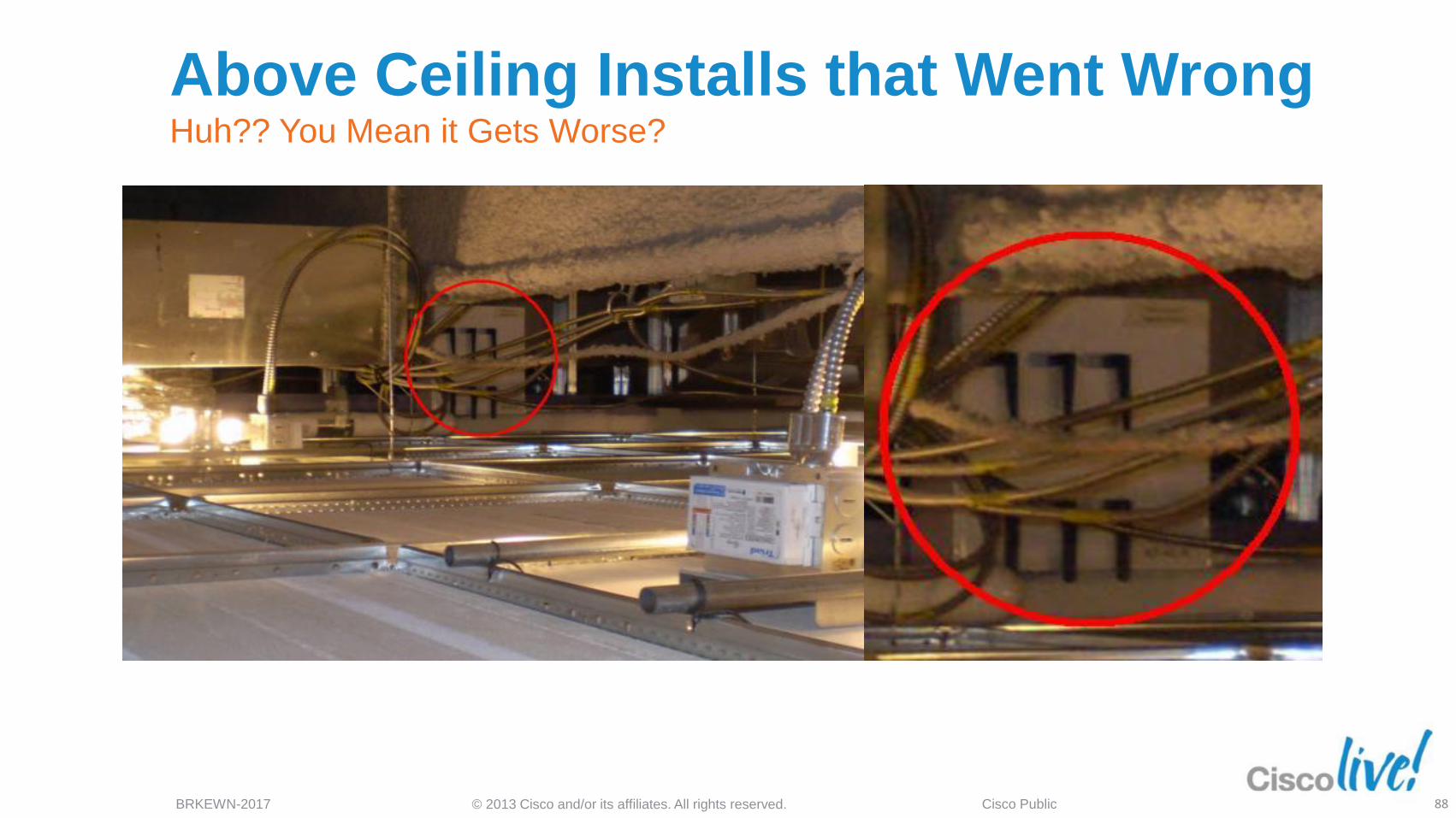
When a dipole is mounted against a metal object you lose all Omni-directional properties. It is now essentially a directional patch suffering from acute multipath distortion problems. Add to that the metal pipes and it is a wonder it works at all
Dipole antennas up against a metal box and large metal pipes create unwanted directionality and multipath distortion – This increases packet retries
Tip: Access Points like light sources should be in the clear and near the users
Above ceiling installs that went wrong Yes it Happens and When it Does it is Expensive to Fix and No One is Happy
87
© 2013 Cisco and/or its affiliates. All rights reserved. BRKEWN-2017 Cisco Public
Above Ceiling Installs that Went Wrong Huh?? You Mean it Gets Worse?
88
© 2013 Cisco and/or its affiliates. All rights reserved. BRKEWN-2017 Cisco Public
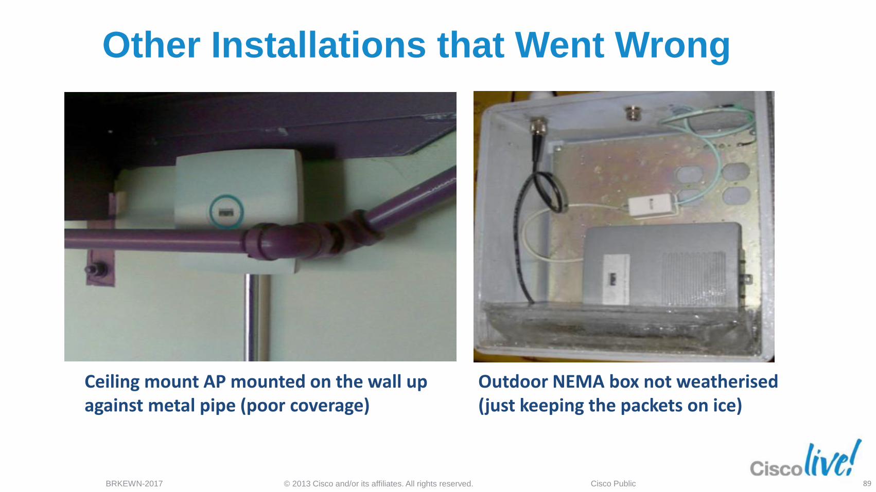
Ceiling mount AP mounted on the wall up against metal pipe (poor coverage)
Outdoor NEMA box not weatherised (just keeping the packets on ice)
Other Installations that Went Wrong
89
© 2013 Cisco and/or its affiliates. All rights reserved. BRKEWN-2017 Cisco Public
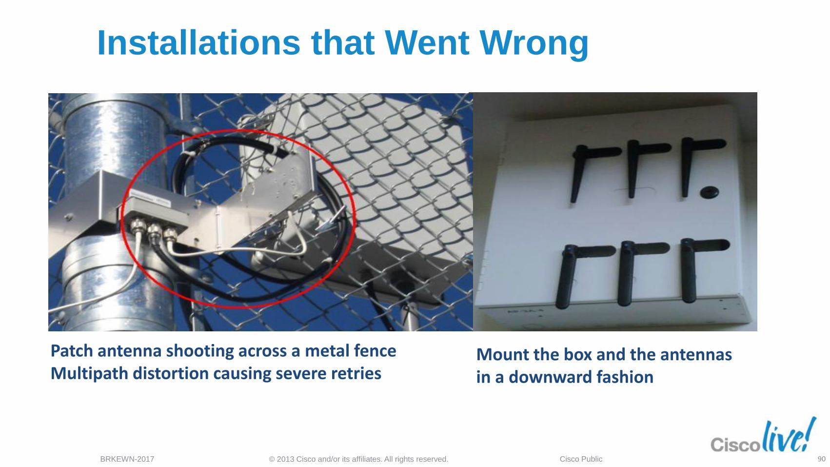
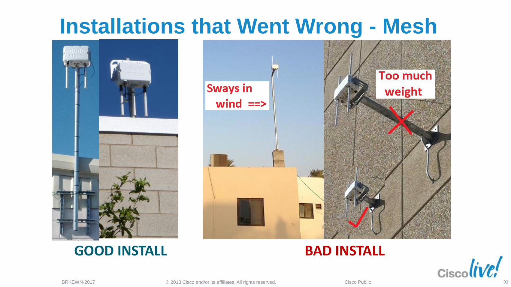
Mount the box and the antennas in a downward fashion
Patch antenna shooting across a metal fence Multipath distortion causing severe retries
Installations that Went Wrong
90
© 2013 Cisco and/or its affiliates. All rights reserved. BRKEWN-2017 Cisco Public
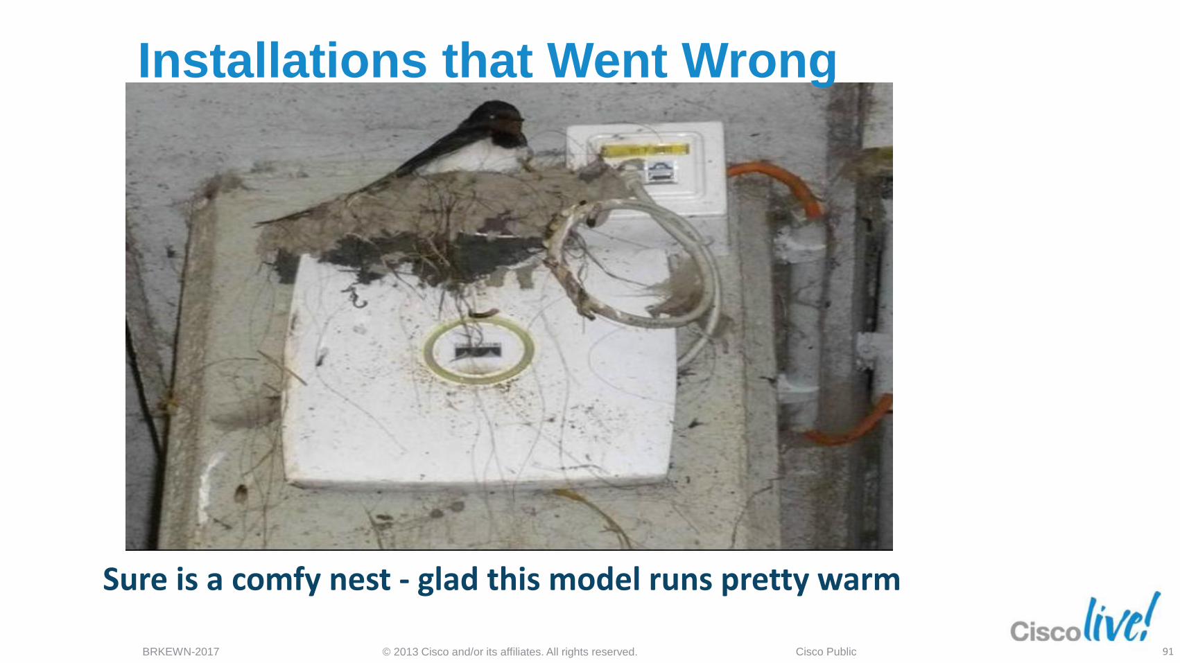
Sure is a comfy nest - glad this model runs pretty warm
Installations that Went Wrong
91
© 2013 Cisco and/or its affiliates. All rights reserved. BRKEWN-2017 Cisco Public
GOOD INSTALL BAD INSTALL
Installations that Went Wrong - Mesh
92
© 2013 Cisco and/or its affiliates. All rights reserved. BRKEWN-2017 Cisco Public
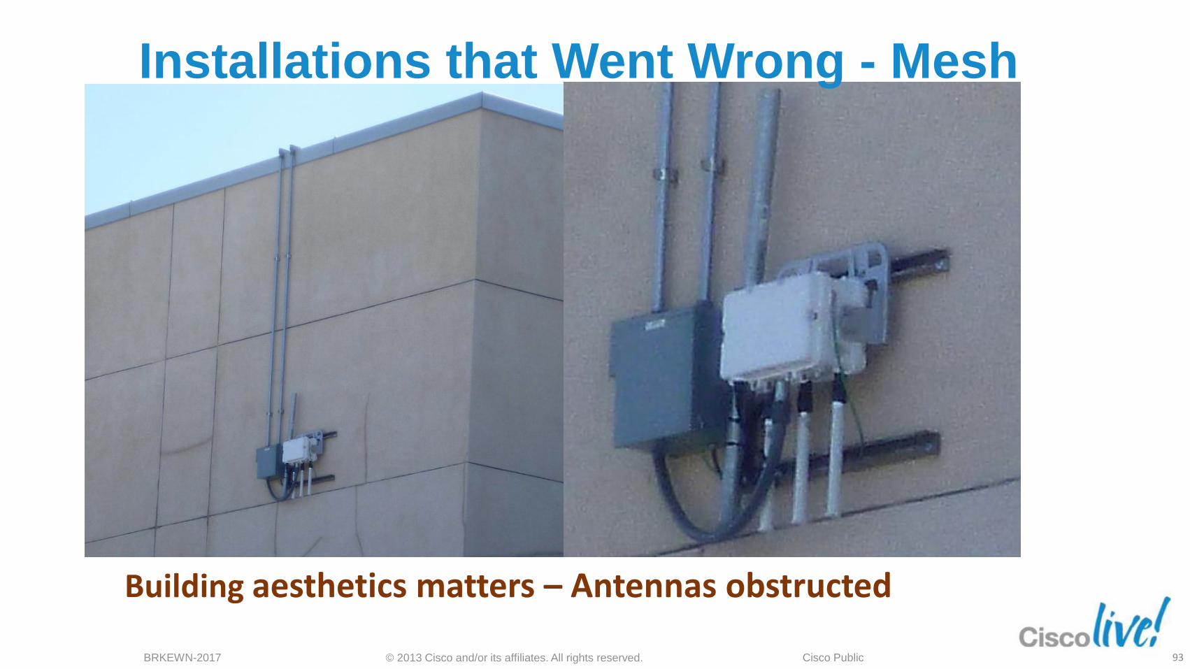
Building aesthetics matters – Antennas obstructed
Installations that Went Wrong - Mesh
93
© 2013 Cisco and/or its affiliates. All rights reserved. BRKEWN-2017 Cisco Public
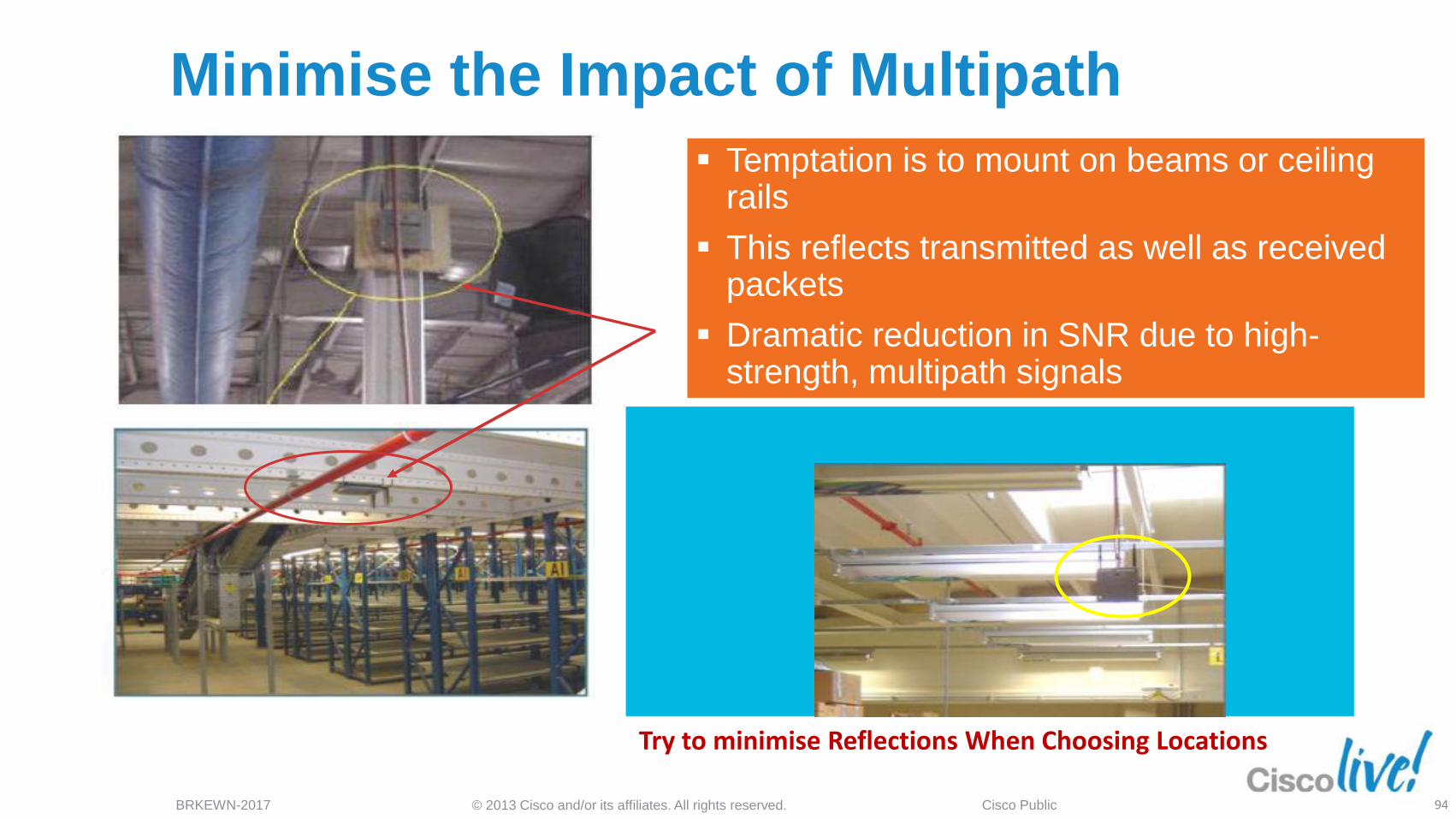
Minimise the Impact of Multipath
Temptation is to mount on beams or ceiling rails
This reflects transmitted as well as received packets
Dramatic reduction in SNR due to high-strength, multipath signals
Try to minimise Reflections When Choosing Locations
94
© 2013 Cisco and/or its affiliates. All rights reserved. BRKEWN-2017 Cisco Public
Summary
“RF Matters”
95
© 2013 Cisco and/or its affiliates. All rights reserved. BRKEWN-2017 Cisco Public
Recommended Reading
“RF Matters” Also see the Cisco AP-3600 deployment guide at this URL http://www.cisco.com/en/US/products/ps11983/products_tech_note09186a0080bb9102.shtml
96

Q & A

© 2013 Cisco and/or its affiliates. All rights reserved. BRKEWN-2017 Cisco Public
Complete Your Online Session
Evaluation Give us your feedback and
receive a Cisco Live 2013 Polo
Shirt!
Complete your Overall Event Survey and 5
Session Evaluations.
Directly from your mobile device on the
Cisco Live Mobile App
By visiting the Cisco Live Mobile Site
www.ciscoliveaustralia.com/mobile
Visit any Cisco Live Internet Station located
throughout the venue
Polo Shirts can be collected in the World of
Solutions on Friday 8 March 12:00pm-2:00pm
98
Don’t forget to activate your
Cisco Live 365 account for
access to all session material,
communities, and on-demand and live activities throughout
the year. Log into your Cisco Live portal and click the
"Enter Cisco Live 365" button.
www.ciscoliveaustralia.com/portal/login.ww
© 2012 Cisco and/or its affiliates. All rights reserved. BRKEWN-2017 Cisco Public

Reference slides
© 2013 Cisco and/or its affiliates. All rights reserved. BRKEWN-2017 Cisco Public
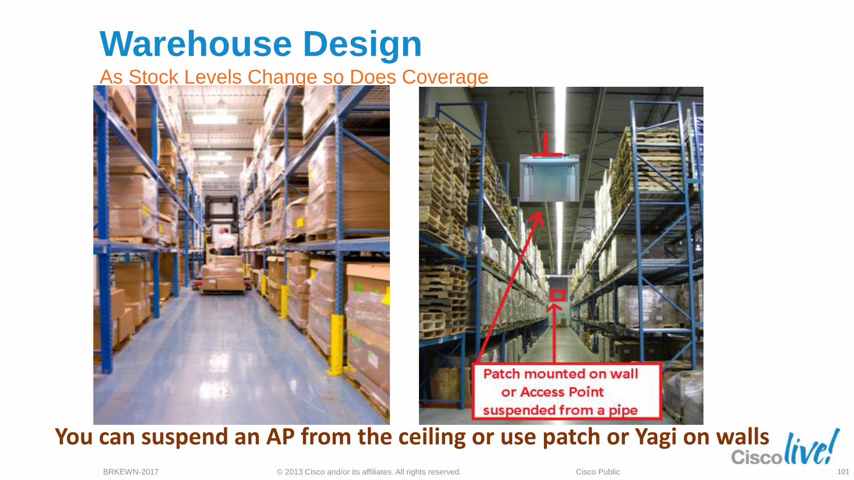
You can suspend an AP from the ceiling or use patch or Yagi on walls
Warehouse Design As Stock Levels Change so Does Coverage
101
© 2013 Cisco and/or its affiliates. All rights reserved. BRKEWN-2017 Cisco Public
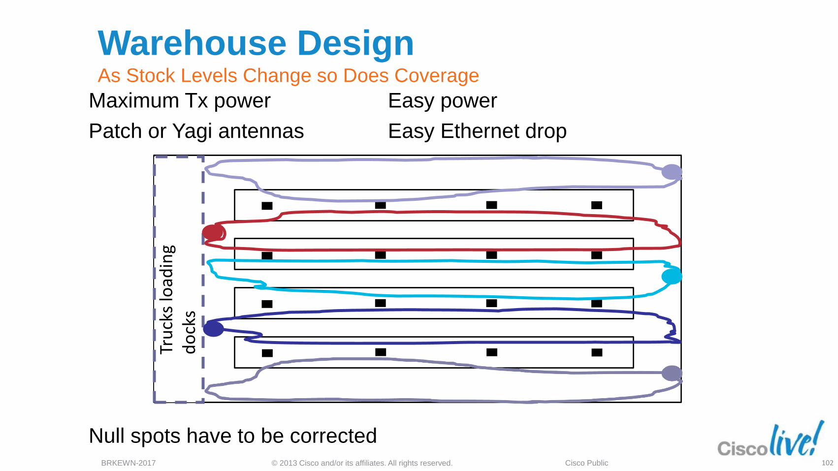
Warehouse Design As Stock Levels Change so Does Coverage
102
Maximum Tx power Easy power
Patch or Yagi antennas Easy Ethernet drop
Null spots have to be corrected
© 2013 Cisco and/or its affiliates. All rights reserved. BRKEWN-2017 Cisco Public
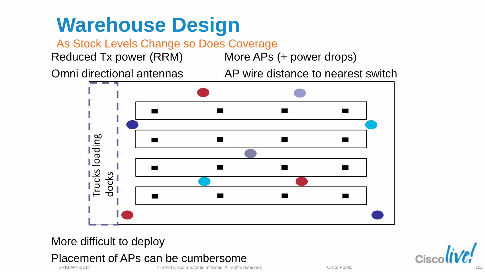
Warehouse Design As Stock Levels Change so Does Coverage
103
Reduced Tx power (RRM) More APs (+ power drops)
Omni directional antennas AP wire distance to nearest switch
More difficult to deploy
Placement of APs can be cumbersome
© 2013 Cisco and/or its affiliates. All rights reserved. BRKEWN-2017 Cisco Public
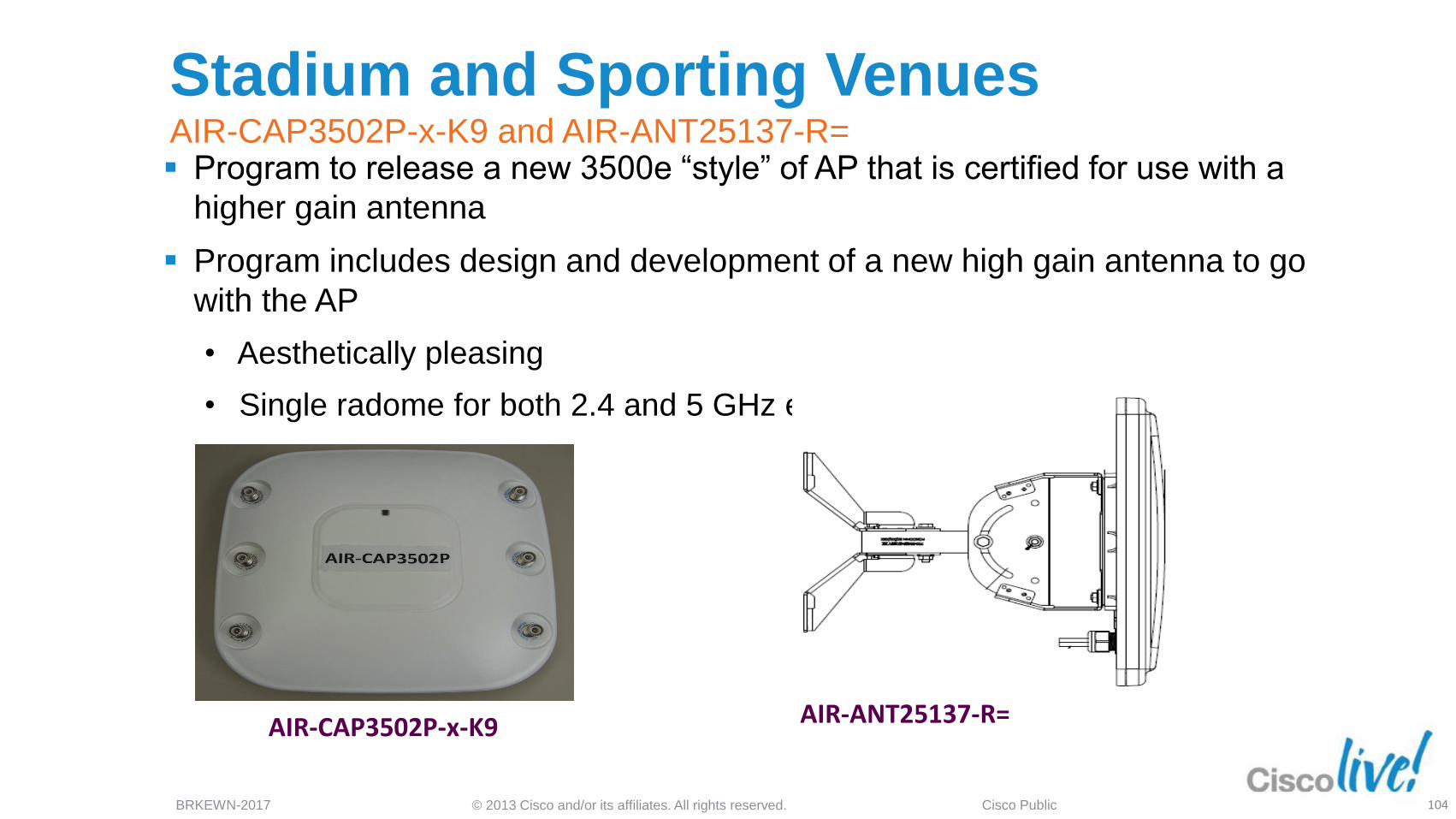
Stadium and Sporting Venues AIR-CAP3502P-x-K9 and AIR-ANT25137-R= Program to release a new 3500e “style” of AP that is certified for use with a
higher gain antenna
Program includes design and development of a new high gain antenna to go
with the AP
• Aesthetically pleasing
• Single radome for both 2.4 and 5 GHz elements
AIR-ANT25137-R= AIR-CAP3502P-x-K9
104
© 2013 Cisco and/or its affiliates. All rights reserved. BRKEWN-2017 Cisco Public
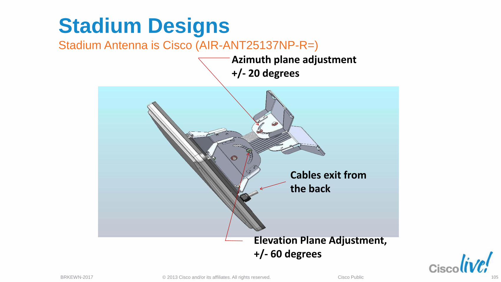
Stadium Designs Stadium Antenna is Cisco (AIR-ANT25137NP-R=)
Azimuth plane adjustment +/- 20 degrees
Elevation Plane Adjustment, +/- 60 degrees
Cables exit from the back
105
© 2013 Cisco and/or its affiliates. All rights reserved. BRKEWN-2017 Cisco Public
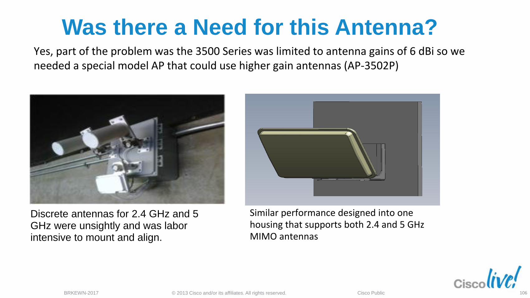
Was there a Need for this Antenna?
Discrete antennas for 2.4 GHz and 5 GHz were unsightly and was labor intensive to mount and align.
Yes, part of the problem was the 3500 Series was limited to antenna gains of 6 dBi so we needed a special model AP that could use higher gain antennas (AP-3502P)
Similar performance designed into one housing that supports both 2.4 and 5 GHz MIMO antennas
106
© 2013 Cisco and/or its affiliates. All rights reserved. BRKEWN-2017 Cisco Public
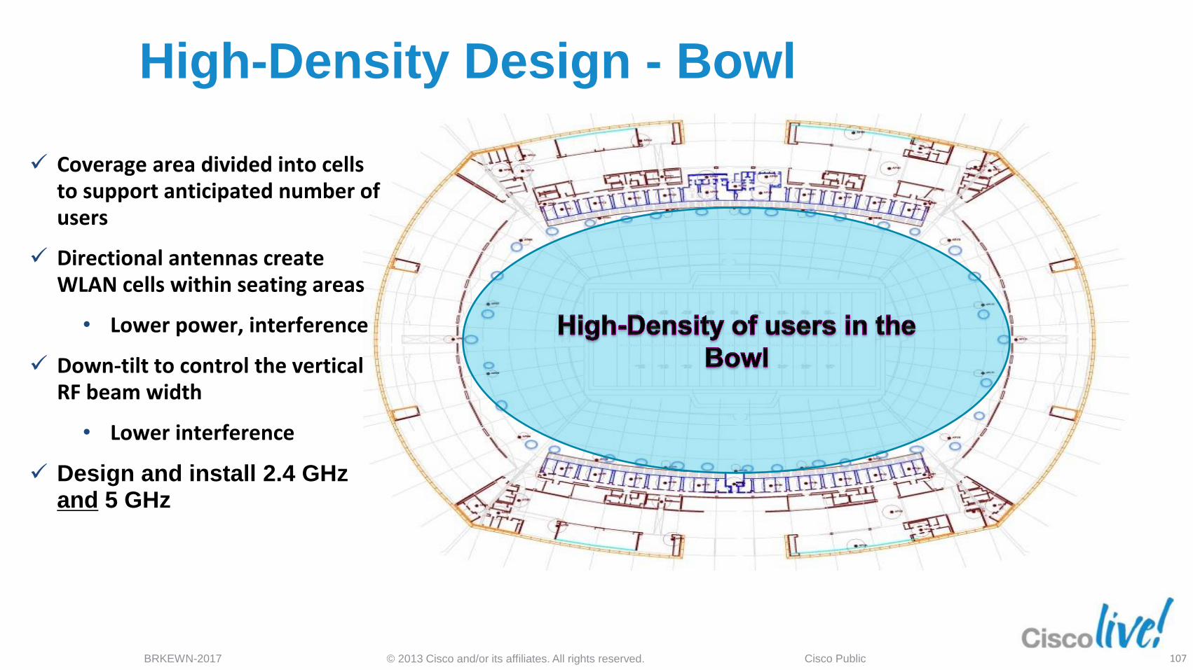
High-Density Design - Bowl
Coverage area divided into cells to support anticipated number of users
Directional antennas create WLAN cells within seating areas
• Lower power, interference
Down-tilt to control the vertical RF beam width
• Lower interference
Design and install 2.4 GHz and 5 GHz
107
© 2013 Cisco and/or its affiliates. All rights reserved. BRKEWN-2017 Cisco Public
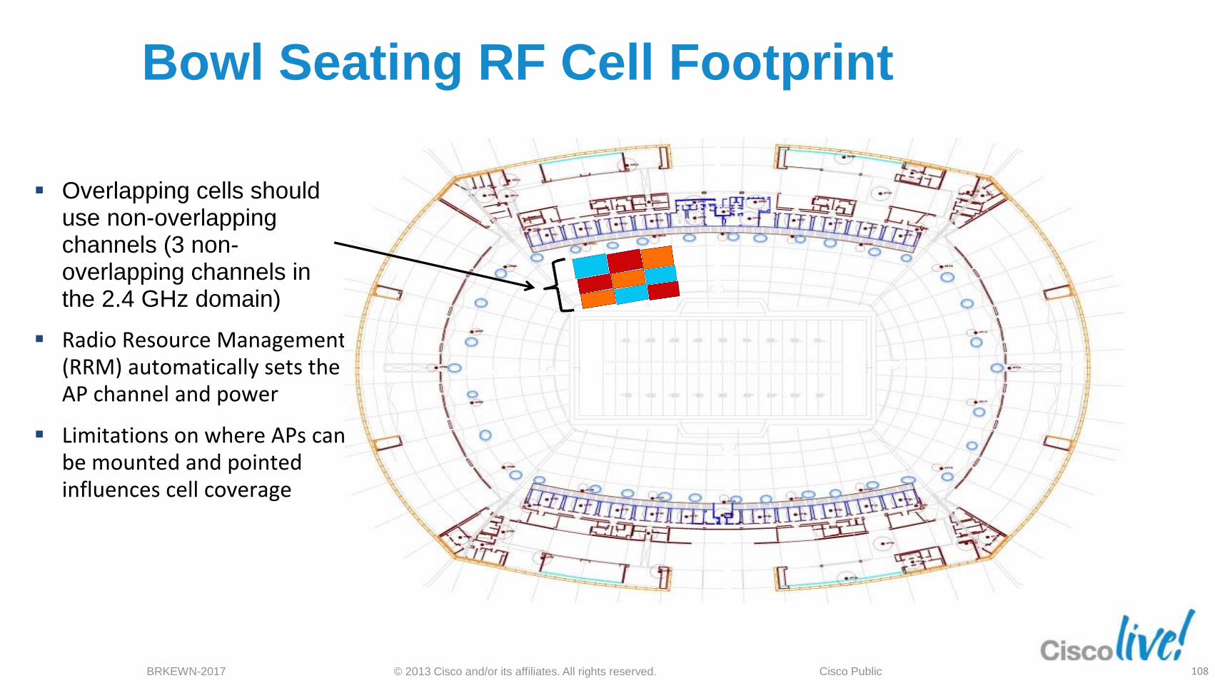
Bowl Seating RF Cell Footprint
Overlapping cells should use non-overlapping channels (3 non-overlapping channels in the 2.4 GHz domain)
Radio Resource Management (RRM) automatically sets the AP channel and power
Limitations on where APs can be mounted and pointed influences cell coverage
108
© 2012 Cisco and/or its affiliates. All rights reserved. BRKEWN-2017 Cisco Public 109