Embed Size (px)
Citation preview


American Journal of Orthodontics and Dentofacial Orthopedics Volume 113. No.2
Ortho Bytes 241
Fig. 8. Activation of preactivated loop. M/F ratio is 10 mm, distal force is 175 gf, uprighting moment is 1750 gf.mm.
bring the end of the loop parallel to the bracket slot. Observe that the loop has contracted, and the end of the loop is now at a distance of more than 6 mm from the canine bracket. The 3 mm extra activation necessary to engage the loop into the bracket increases the force and counteracts most of the gain from the 40° preactivation. The loop of Fig. 6. where. only a moment is applied in order to bring the free end parallel to the bracket slot. is said to be in the neutral position. The moment necessary to bring the free end of the wire parallel to the bracket slot is called the activating moment4 or the residual momelll.2
Is there a way to avoid loop contraction? The answer lies in the way that the preactivation bends are placed. What we need is a loop that assumes the shape of Fig. IA not when passive. but when in its neutral position, i.e., ""hen the activating moment is applied. When such a loop is engaged into the canine bracket, it should produce a force and moment equal to that of Fig. I B, plus an additional moment equal to the activating moment. Using the numbers found above, we can calculate that the activating moment should be approximately 980 gf.mm. This, added to the 770 gf.mm moment produced in Fig.lB, will give a total moment of 1750 gf.mm. Because the force is 175 gf. an MIF ratio of 10 mm should result .
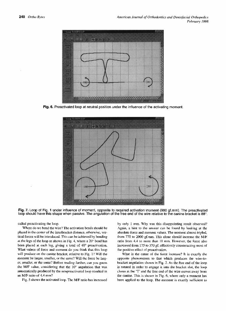
What is the passive shape of such a loop? To arrive at the preactivated shape of the T-loop, we apply a moment equal in magnitude but opposite in direction to the activating moment. This moment was applied to the loop of Fig. I and the result is shown in Fig. 7. The loop has now assumed the correct preactivated shape but is still under the influence of the moment. It is a simple matter to make the wire passive. by selecting the appropriate program command that removes the moment but retains the shape of the wire. Observe that activation is not localized at two points on the wire but is spread out along the entire loop. This results in an opening of the loop that counter-
acts the contraction produced by the activating moment. As expected, the shape of the new preactivated loop at the neutral position is identical to Fig. I. The loop engaged in the canine bracket is shown in Fig. 8. Forces and moments are as predicted.
Conclusions Computer simulation of orthodontic loops can help us visu
alize various factors of loop design that interact to produce the
force/moment properties of loops. The computer program used
here has special features that allow calculation of the neutral
position of loops and of the preactivated shape of the wire.
Assessment of the neutral position of preactivated loops is
important in predicting loop properties.
Preactivation may need to involve the whole loop. rather
than a few points on the wire.
References I . Burstone CJ, Koenig HA. Optimizing anterior and canine
retraction. Am J Orthod 1975;67:11-23.
2. Burstone CJ. The segmented arch approach to space clo
sure. Am J Orthod 1982;82:361-78.
3. Halazonetis DJ. Design and test orthodontic loops using
your computer. Am J Orthod Dentofacial Orthop
1997; III :346-8.
4. Marcotte MR. Biomechanics in orthodontics. Toronto B.C.
Decker Inc., 1990.
Reprint requests to : D. Halazonetis, 6 Menandrow Street,
Kilisia 14561 Greece. email: [email protected]. Web address for
program downloading; hltp:llw4u. eexi.gr/-dhal