Embed Size (px)
Citation preview
Understanding IMS
2 Understanding IMS
Introducing IMS ........................................................................................................................ 4 IMS Architecture ...................................................................................................................... 5 IMS Procedures ......................................................................................................................... 6 Bearer Establishment and QoS ................................................................................................. 7 Default Bearer ........................................................................................................................... 7 Dedicated Bearer ...................................................................................................................... 7 Example Scenario and Testing Methods .................................................................................. 8 IMS Protocols ............................................................................................................................ 8 SIP ............................................................................................................................................. 9 SigComp (Signalling Compression) ........................................................................................ 10 Session Description Protocol .................................................................................................. 10 Codecs for Voice ..................................................................................................................... 11 IMS Authentication and Security ............................................................................................ 12 Authentication and Protection Steps in IMS Networks .......................................................... 12 3GPP AKA Operation in IMS .................................................................................................. 13 Supplementary Service ........................................................................................................... 14 IMS Voice and Related LTE Physical Layer Features ............................................................... 14 IMS Testing Tools .................................................................................................................... 16 For Advanced IMS VoLTE Testing and Development ............................................................. 19 Solution Overview .................................................................................................................. 20 Conclusion .............................................................................................................................. 22 Abbreviations ......................................................................................................................... 22

3w w w. a n r i t s u . c o m
4 Understanding IMS
Introducing IMS
IMS stands for IP Multimedia Subsystem and is now known as a key technology defining the modern version of the infrastructure that will deliver communications around the world. It is shaping the future strategy of numerous operators focusing on providing telephony and other services over their 3GPP IP core.
Numerous IP telephony and multimedia services are widely available on the traditional internet. However, IMS allows operators to control the Quality of Service of each IMS application from end to end and provides a secure authentication and security access based on the user’s SIM card. It will also enable full control to charge the user for the services and ensure interoperability between other networks and terminals.
IMS comes with new challenges in the telecom industry especially for UE developers. The IMS specification standardised by 3GPP has eased the integration with the internet by using IETF wherever possible (e.g. SIP). It brings extensive flexibility in terms of design for developers to build Fixed-Mobile Convergence (FMC) service with a large selection of protocol and codecs to choose from, but it also increases the overall complexity.
This guide intends to provide a general overview of IMS in relation to the main components to be tested when it comes to User Equipment IMS testing.
5w w w. a n r i t s u . c o m
IMS Architecture
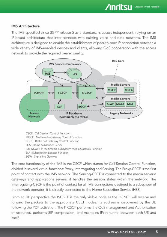
The IMS specified since 3GPP release 5 as a standard, is access-independent, relying on an IP-based architecture that inter-connects with existing voice and data networks. The IMS architecture is designed to enable the establishment of peer-to-peer IP connection between a wide variety of IMS-enabled devices and clients, allowing QoS cooperation with the access network to provide the required bearer quality.
CSCF : Call Session Control Function MGCF : Multimedia Gateway Control Function BGCF : Brake out Gateway Control Function HSS : Home Subscriber Server IMS-MGW : IP Multimedia Subsystem Media Gateway Function SLF : Subscription Locator Function SGW : Signalling Gateway
The core functionality of the IMS is the CSCF which stands for Call Session Control Function, divided in several virtual functions: Proxy, Interrogating and Serving. The Proxy-CSCF is the first point of contact with the IMS network. The Serving-CSCF is connected to the media servers/gateways and applications servers, it handles the session states within the network. The Interrogating-CSCF is the point of contact for all IMS connections destined to a subscriber of the network operator; it is directly connected to the Home Subscriber Service (HSS).
From an UE perspective the P-CSCF is the only visible node as the P-CSCF will receive and forward the packets to the appropriate CSCF nodes. Its address is discovered by the UE following the PDP activation. The P-CSCF performs the QoS management and Authorisation of resources, performs SIP compression, and maintains IPsec tunnel between each UE and itself.
P-CSCF I-CSCF S-CSCF
SLF BGCF
AccessNetwork
HSS AS
IMS Services Framework
MRFP MRFC
Media Servers
SGW MGF
Media Servers
MGCF
Legacy NetworksIP Backbone(Commonly via MPLS)
IMS Core
6 Understanding IMS
IMS Procedures
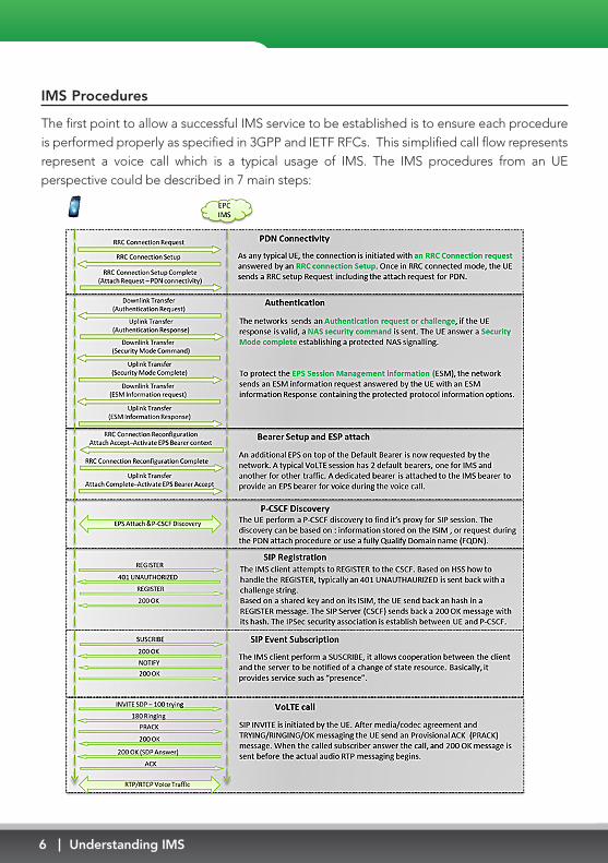
The first point to allow a successful IMS service to be established is to ensure each procedure is performed properly as specified in 3GPP and IETF RFCs. This simplified call flow represents represent a voice call which is a typical usage of IMS. The IMS procedures from an UE perspective could be described in 7 main steps:
7w w w. a n r i t s u . c o m
Bearer establishment and QoS
One of the strong advantages of using IMS combined with the LTE operator network is the ability to establish specific virtual pipes called “EPS bearer” providing a given quality of service. It defines how the UE data is treated when it travels across the network. Hence, full control of the expected quality for Voice or Video service can be ensured. From a testing perspective is it essential to ensure those bearers are properly configured.
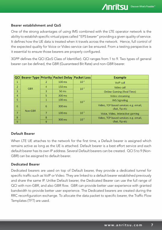
3GPP defines the QCI (QoS Class of Identifier). QCI ranges from 1 to 9. Two types of general bearer can be defined, the GBR (Guaranteed Bit Rate) and non-GBR bearer.
Default Bearer
When LTE UE attaches to the network for the first time, a Default bearer is assigned which remains active as long as the UE is attached. Default bearer is a best effort service and each default bearer has its own IP address. Several Default bearers can be created. QCI 5 to 9 (Non- GBR) can be assigned to default bearer.
Dedicated Bearer
Dedicated bearers are used on top of Default bearer, they provide a dedicated tunnel for specific traffic such as VoIP or Video. They are linked to a default bearer established previously and share the same IP. Unlike Default bearer, the Dedicated Bearer can use the full range of QCI with non-GBR, and also GBR flow. GBR can provide better user experience with granted bandwidth to provide better user experience. The Dedicated bearers are created during the RRC reconfiguration exchange. To allocate the data packet to specific bearer, the Traffic Flow Templates (TFT) are used.
8 Understanding IMS
Example scenario and testing methods
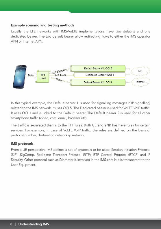
Usually the LTE networks with IMS/VoLTE implementations have two defaults and one dedicated bearer. The two default bearer allow redirecting flows to either the IMS operator APN or Internet APN.
In this typical example, the Default bearer 1 is used for signalling messages (SIP signalling) related to the IMS network. It uses QCI 5. The Dedicated bearer is used for VoLTE VoIP traffic. It uses QCI 1 and is linked to the Default bearer. The Default bearer 2 is used for all other smartphone traffic (video, chat, email, browser etc).
The traffic is separated thanks to the TFT rules: Both UE and eNB has have rules for certain services. For example, in case of VoLTE VoIP traffic, the rules are defined on the basis of protocol number, destination network ip network.
IMS protocols
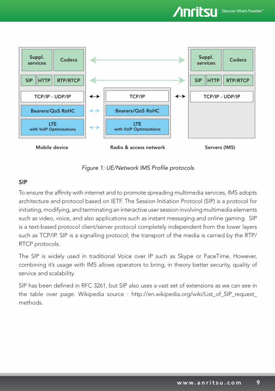
From a UE perspective IMS defines a set of protocols to be used: Session Initiation Protocol (SIP), SigComp, Real-time Transport Protocol (RTP), RTP Control Protocol (RTCP) and IP Security. Other protocol such as Diameter is involved in the IMS core but is transparent to the User Equipment.
9w w w. a n r i t s u . c o m
Suppl.services
Codecs
SIP HTTP RTP/RTCP
TCP/IP - UDP/IP
Bearers/QoS RoHC
LTEwith VoIP Optimizations
TCP/IP
Bearers/QoS RoHC
LTEwith VoIP Optimizations
Suppl.services
Codecs
SIP HTTP RTP/RTCP
TCP/IP - UDP/IP
Mobile device Radio & access network Servers (IMS)
Figure 1: UE/Network IMS Profile protocols
SIP
To ensure the affinity with internet and to promote spreading multimedia services, IMS adopts architecture and protocol based on IETF. The Session Initiation Protocol (SIP) is a protocol for initiating, modifying, and terminating an interactive user session involving multimedia elements such as video, voice, and also applications such as instant messaging and online gaming. SIP is a text-based protocol client/server protocol completely independent from the lower layers such as TCP/IP. SIP is a signalling protocol; the transport of the media is carried by the RTP/RTCP protocols.
The SIP is widely used in traditional Voice over IP such as Skype or FaceTime. However, combining it’s usage with IMS allows operators to bring, in theory better security, quality of service and scalability.
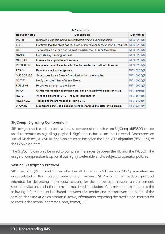
SIP has been defined in RFC 3261, but SIP also uses a vast set of extensions as we can see in the table over page: Wikipedia source : http://en.wikipedia.org/wiki/List_of_SIP_request_methods.
10 Understanding IMS
SigComp (Signaling Compression)
SIP being a text-based protocol, a lossless compression mechanism SigComp (RF3320) can be used to reduce its signalling payload. SigComp is based on the Universal Decompressor Virtual Machine (UDVM). IMS servers are often based on the DEFLATE algorithm (RFC 1951) or the LZSS algorithm.
The SigComp can only be used to compress messages between the UE and the P-CSCF. The usage of compression is optional but highly preferable and is subject to operator policies.
Session Description Protocol
SIP uses SDP (RFC 3264) to describe the attributes of a SIP session. SDP parameters are encapsulated in the message body of a SIP request. SDP is a human readable protocol intended for describing multimedia sessions for the purposes of session announcement, session invitation, and other forms of multimedia initiation. At a minimum this requires the following information to be shared between the sender and the receiver: the name of the session, the time at which session is active, information regarding the media and information to receive the media (addresses, port, format, …)
11w w w. a n r i t s u . c o m
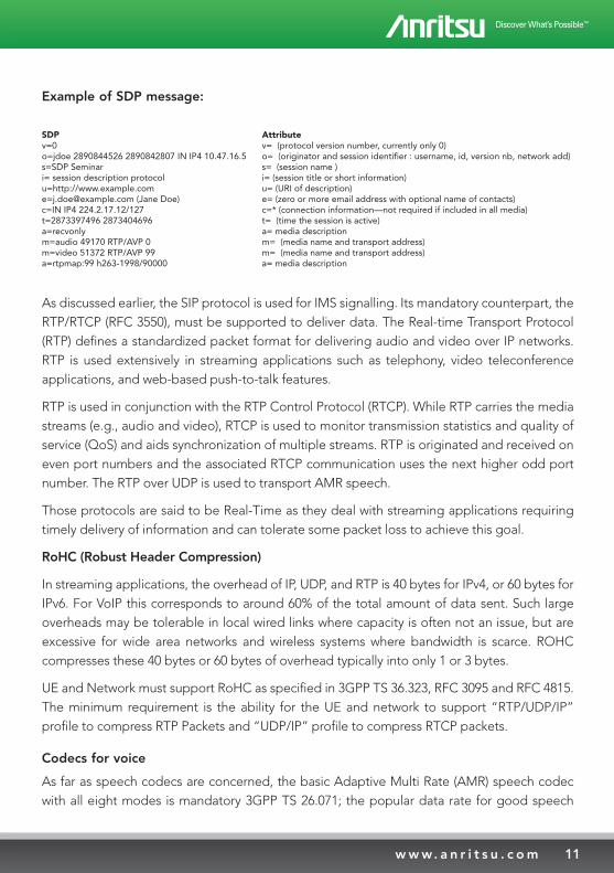
Example of SDP message:
SDPv=0o=jdoe 2890844526 2890842807 IN IP4 10.47.16.5s=SDP Seminari= session description protocolu=http://[email protected] (Jane Doe)c=IN IP4 224.2.17.12/127t=2873397496 2873404696a=recvonlym=audio 49170 RTP/AVP 0m=video 51372 RTP/AVP 99a=rtpmap:99 h263-1998/90000
Attributev= (protocol version number, currently only 0)o= (originator and session identifier : username, id, version nb, network add)s= (session name )i= (session title or short information)u= (URI of description)e= (zero or more email address with optional name of contacts)c=* (connection information—not required if included in all media)t= (time the session is active)a= media descriptionm= (media name and transport address)m= (media name and transport address)a= media description
As discussed earlier, the SIP protocol is used for IMS signalling. Its mandatory counterpart, the RTP/RTCP (RFC 3550), must be supported to deliver data. The Real-time Transport Protocol (RTP) defines a standardized packet format for delivering audio and video over IP networks. RTP is used extensively in streaming applications such as telephony, video teleconference applications, and web-based push-to-talk features.
RTP is used in conjunction with the RTP Control Protocol (RTCP). While RTP carries the media streams (e.g., audio and video), RTCP is used to monitor transmission statistics and quality of service (QoS) and aids synchronization of multiple streams. RTP is originated and received on even port numbers and the associated RTCP communication uses the next higher odd port number. The RTP over UDP is used to transport AMR speech.
Those protocols are said to be Real-Time as they deal with streaming applications requiring timely delivery of information and can tolerate some packet loss to achieve this goal.
RoHC (Robust Header Compression)
In streaming applications, the overhead of IP, UDP, and RTP is 40 bytes for IPv4, or 60 bytes for IPv6. For VoIP this corresponds to around 60% of the total amount of data sent. Such large overheads may be tolerable in local wired links where capacity is often not an issue, but are excessive for wide area networks and wireless systems where bandwidth is scarce. ROHC compresses these 40 bytes or 60 bytes of overhead typically into only 1 or 3 bytes.
UE and Network must support RoHC as specified in 3GPP TS 36.323, RFC 3095 and RFC 4815. The minimum requirement is the ability for the UE and network to support “RTP/UDP/IP” profile to compress RTP Packets and “UDP/IP” profile to compress RTCP packets.
Codecs for voice
As far as speech codecs are concerned, the basic Adaptive Multi Rate (AMR) speech codec with all eight modes is mandatory 3GPP TS 26.071; the popular data rate for good speech
12 Understanding IMS
quality is 12.2 kbps. VoLTE optionally supports the AMR wideband codec with eight modes (3GPP TS 26.093), where the data rate of 12.65 kbps (often called the anchor bit rate) is expected to be popular.
When transmitting, the UE and the entities in the IMS core network that terminate the user plane shall be capable of aligning codec mode changes to every frame border, and shall also be capable of restricting codec mode changes to be aligned to every other frame border. When receiving, the UE and the entities in the IMS core network that terminate the user plane shall allow codec mode changes at any frame border and to any codec mode within the negotiated codec mode set.
IMS authentication and security
There is different aspect to the security in IMS networks from the UE perspective. They are covered by the IMS AKA security mechanism. The IMS AKA has two main functions in this case:
1. Authentication of a UE by the home S-CSCF.
2. Protection of all traffic between UE and P-CSCF on the Gm interface on dual IPsec channels.
When a VoLTE client needs to connect to an IMS network, it has to authenticate the network while the network also needs to make sure that only the correct user is registered to its network. AKA Digest is the schemes to authenticate the VoLTE client to the IMS server. The AKA digest is a combination of the 3GPP AKA and the HTTP Digest used in the webserver world (RFC2617). In order to use 3GPP AKA with IMS, the parameters from AKA are mapped onto http digest [RFC3310].
Authentication and protection steps in IMS networks:
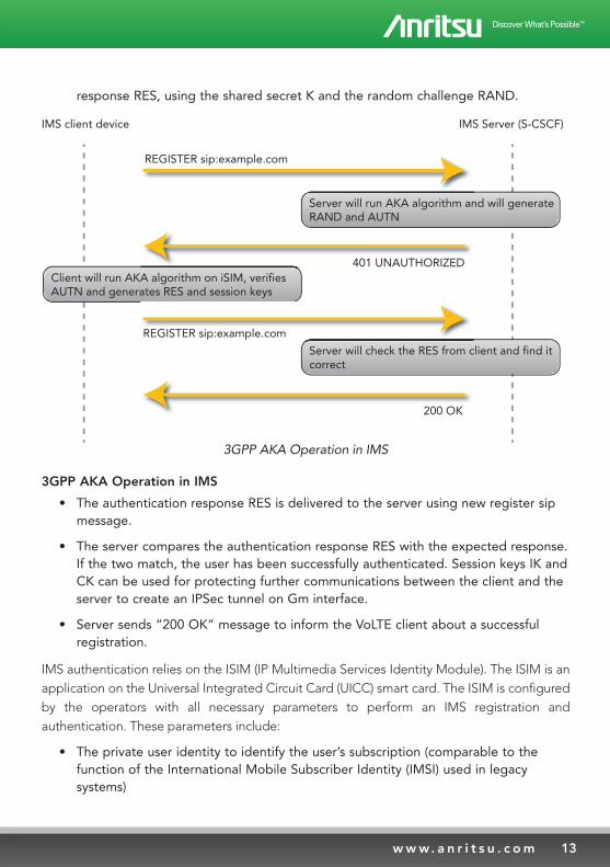
• VoLTE Client sends SIP register request to IMS Server. The SIP register request contains IMS related identities (private identity, public identity, URI, etc)
• The IMS Server (S-CSCF) obtains an authentication vector and SQN from HSS that contains a random challenge RAND, authentication token AUTN, expected authentication result XRES, a session key for integrity check IK, and a session key for encryption CK.
• The server sends an authentication request, a message “401 UNAUTHORIZED”, containing the random challenge RAND, and the network authenticator token AUTN.
• The client verifies the AUTN with the ISIM. If the verification is successful, the network has been authenticated. The client then produces an authentication
13w w w. a n r i t s u . c o m
response RES, using the shared secret K and the random challenge RAND.
Server will run AKA algorithm and will generateRAND and AUTN
Client will run AKA algorithm on iSIM, verifiesAUTN and generates RES and session keys
Server will check the RES from client and find itcorrect
REGISTER sip:example.com
401 UNAUTHORIZED
REGISTER sip:example.com
200 OK
IMS client device IMS Server (S-CSCF)
3GPP AKA Operation in IMS
3GPP AKA Operation in IMS
• The authentication response RES is delivered to the server using new register sip message.
• The server compares the authentication response RES with the expected response. If the two match, the user has been successfully authenticated. Session keys IK and CK can be used for protecting further communications between the client and the server to create an IPSec tunnel on Gm interface.
• Server sends “200 OK” message to inform the VoLTE client about a successful registration.
IMS authentication relies on the ISIM (IP Multimedia Services Identity Module). The ISIM is an application on the Universal Integrated Circuit Card (UICC) smart card. The ISIM is configured by the operators with all necessary parameters to perform an IMS registration and authentication. These parameters include:
• The private user identity to identify the user’s subscription (comparable to the function of the International Mobile Subscriber Identity (IMSI) used in legacy systems)
14 Understanding IMS
• One or more public user identities to identify the user
• The home network domain name to identify the name of the home network during registration and to address the SIP REGISTER request.
Supplementary services
The Supplementary services enable the support for some extra services requested by the VoLTE profile stipulated in GSMA IR.92. Supplementary services are part of the MMTel service standardized as 3GPP Rel.7. By adoption TAS (Telephony Application Server), MMTel enables to provide supplementary service same as CS technology.
There are two merits to compare with legacy CS network.
• Not only voice call, subscriber can use combined communication with video, text, messaging and file transportation.
• The data format of supplementary service is XML format. And setting protocol is defined as XCAP.
These functons are to enable supplementary services which are consistent across both the fixed line telephone network and the mobile network, and are not dependant or specific to one particular type of network. For example, the Originating Identification Presentation (OIP) service provides the terminating user a way to receive identity information to identify the originating user, i.e. to see who is calling you when you receive a call.
Another example would be the supplementary service Communication Hold (HOLD) that enables a user to suspend the reception of media stream(s) from an established IP multimedia session, and resume them at a later time. For supplementary service configuration, support of XCAP is required on both the UE and the network side. XCAP in this case is used for manipulating the data related to supplementary services.
IMS Voice and related LTE physical layer features
IMS and SIP are necessary technologies for the deployment of VoIP in an LTE environment, but it is ultimately the introduction of LTE RAN features that creates the differentiation between VoLTE and VoIP. We already mentioned the importance of the dedicated Bearers allowing for the prioritization of VoLTE audio packets over all other best-effort traffic with the QCI mechanism. The Robust Header Compression will also play an important role by reducing the bandwidth associated with the headers used to transport relatively small encoded audio packets. However the physical layer features also have an important role to play in the optimisation of IMS voice:
15w w w. a n r i t s u . c o m
• The Semi-Persistent Scheduling (SPS) greatly reduces the complexity and overhead of scheduling small and periodic VoLTE audio packets. Instead of providing an allocation grant for each packet, it allows a semi-persistent allocation of downlink and uplink physical layer resource blocks to transport the audio traffic. It then reduces the overall processing overhead and mitigates congestion by providing more bandwidth to accommodate additional users. The SPS periodicity is indicated in the Radio Resource Control (RRC) messages.
• The discontinuous Reception (DRX) helps conserve battery life of the UE during a VoLTE call. Discontinuous Reception (DRX) takes advantage of these silent periods to turn off the RF receiver of the UE, as well as other entities such as A/D converters and digital signal processors associated with downlink demodulation. This reduces the drain on the device’s battery and increases talk and standby usage time. RRC messaging is used to enable DRX and establish the UE receiver’s on/off pattern.
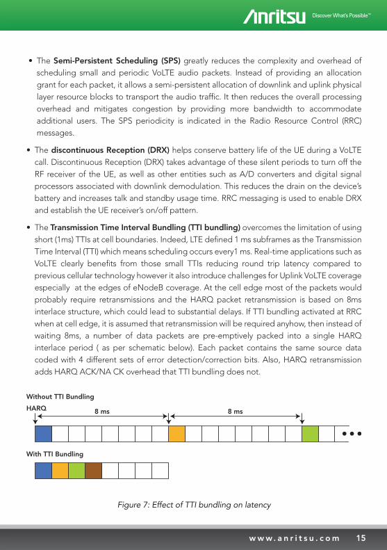
• The Transmission Time Interval Bundling (TTI bundling) overcomes the limitation of using short (1ms) TTIs at cell boundaries. Indeed, LTE defined 1 ms subframes as the Transmission Time Interval (TTI) which means scheduling occurs every1 ms. Real-time applications such as VoLTE clearly benefits from those small TTIs reducing round trip latency compared to previous cellular technology however it also introduce challenges for Uplink VoLTE coverage especially at the edges of eNodeB coverage. At the cell edge most of the packets would probably require retransmissions and the HARQ packet retransmission is based on 8ms interlace structure, which could lead to substantial delays. If TTI bundling activated at RRC when at cell edge, it is assumed that retransmission will be required anyhow, then instead of waiting 8ms, a number of data packets are pre-emptively packed into a single HARQ interlace period ( as per schematic below). Each packet contains the same source data coded with 4 different sets of error detection/correction bits. Also, HARQ retransmission adds HARQ ACK/NA CK overhead that TTI bundling does not.
Without TTI Bundling
HARQ
With TTI Bundling
8 ms 8 ms
Figure 7: Effect of TTI bundling on latency
16 Understanding IMS
While much focus has been placed in testing a UE’s IMS connectivity and SIP signaling conformance, ultimate success of carrier-grade VoLTE deployments will depend on fully integrated testing of a UE’s signaling along with the negotiation, establishment and usage of the associated RAN features mentioned above.
IMS Testing Tools: Functional Testing, Performance Testing, and Quality Testing
At each level of system integration, tests may be focused on basic functionality, or performance, or quality. For IMS and specifically when it comes to VoLTE, some of the more important functional tests include:
• IMS registration
• IMS security procedures
• Device (SIP) addressing
• Call processing including abnormal call handling
• Call conferencing and other supplementary services such as call forwarding
• Call drop and reestablishment
• Emergency calls
• Codecs and DTMF
• Video calls
During performance testing, some areas of key interest are:
• Jitter buffer management
• Lost packet and erroneous packet handling
• Call setup latency
• Call completion rate
• Ringback tones
Finally, important quality tests include acoustic audio tests as defined in 3GPP TS 26.132, PESQ/POLQA scores, acoustic echo, and the effects of transcoders as would occur in VoLTE-to-non-VoLTE calling.
17w w w. a n r i t s u . c o m
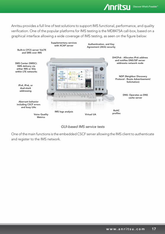
Anritsu provides a full line of test solutions to support IMS functional, performance, and quality verification. One of the popular platforms for IMS testing is the MD8475A call-box, based on a graphical interface allowing a wide coverage of IMS testing, as seen on the figure below:
Built-in CFCS server VoLTEand SMS over IMS
Supplementary serviceswith XCAP server
Authentication, and KeyAgreement (AKA) security
DHCPv6 : Allocates IPv6 addressand notifies DNS/SIP server
addressto network node
NDP (Neighbor DiscoveryProtocol : Route Advertisement/
Solicitation)
DNS: Operates as DNScache server
RoHCprofilesVirtual UA
IMS logs analysisVoice Quailty
Metrics
Aberrant behaviorincluding CSCF errors
and busy UAs
IPv4, IPv6, ordual-stackaddressing
SMS Center (SMSC):SMS delivery viaeither IMS or SGs
within LTE networks
GUI-based IMS service tests
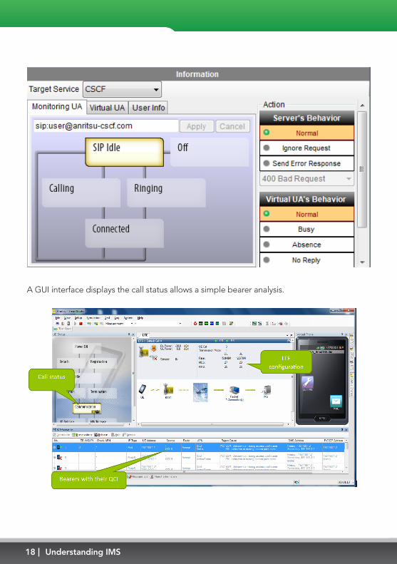
One of the main functions is the embedded CSCF server allowing the IMS client to authenticate and register to the IMS network.
18 Understanding IMS
A GUI interface displays the call status allows a simple bearer analysis.
19w w w. a n r i t s u . c o m
For advanced IMS VoLTE testing and development
R&D engineers also need a solution that provides the flexibility to test all the common scenarios along with the ability to create their own more specialized test cases. The right solution needs full stack control for not just LTE, but also IMS and legacy protocols. Voice and video services are susceptible to network impairments such as packet loss and delay. This means that objective and repeatable measurements of factors affecting the end user experience are
critical to success during the protocol development phase.
20 Understanding IMS
Solution Overview
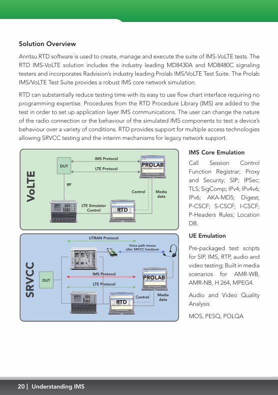
Anritsu RTD software is used to create, manage and execute the suite of IMS-VoLTE tests. The RTD IMS-VoLTE solution includes the industry leading MD8430A and MD8480C signaling testers and incorporates Radvision’s industry leading Prolab IMS/VoLTE Test Suite. The Prolab IMS/VoLTE Test Suite provides a robust IMS core network simulation.
RTD can substantially reduce testing time with its easy to use flow chart interface requiring no programming expertise. Procedures from the RTD Procedure Library (IMS) are added to the test in order to set up application layer IMS communications. The user can change the nature of the radio connection or the behaviour of the simulated IMS components to test a device’s behaviour over a variety of conditions. RTD provides support for multiple access technologies allowing SRVCC testing and the interim mechanisms for legacy network support.
DUT
RF
IMS Protocol
LTE Protocol
LTE SimulatorControl
Control MediadataV
oLT
E
RTD
PROLAB
Control Mediadata
SRV
CC
CRTD
PROLABDUT
IMS Protocol
LTE Protocol
Voice path movesafter SRVCC handover
UTRAN Protocol
IMS Core Emulation
Call Session Control Function Registrar; Proxy and Security; SIP; IPSec; TLS; SigComp; IPv4; IPv4v6; IPv6; AKA-MD5; Digest; P-CSCF; S-CSCF; I-CSCF; P-Headers Rules; Location DB.
UE Emulation
Pre-packaged test scripts for SIP, IMS, RTP, audio and video testing; Built in media scenarios for AMR-WB, AMR-NB, H.264, MPEG4.
Audio and Video Quality Analysis
MOS, PESQ, POLQA
21w w w. a n r i t s u . c o m
Specification Compliance
An extensive library of built in IMS test cases enables standards compliance testing:
GSMA IR.92 (Voice and SMS) , GSMA IR.94 (Video) ,GSMA IR.88 (LTE Roaming) , GSMA IR.64 (SRVCC), 3GPP TS26.114 (Media handling and interaction).
Rich Communication Services
The solution is ready for testing Rich Communications Suite (RCS) functions such as presence, instant messaging; file transfer, address book, XML Document Management (XDM) with XCAP Server Simulation.

22 Understanding IMS
Conclusion
IMS represents a fantastic opportunity for operators and developers to provide a totally new user experience by using a dedicated architecture. The need for a unified and interoperable infrastructure to carry voice over LTE is driving the VoLTE IMS, and future services taking advantages of this infrastructure are yet to come. We have seen in this guide that IMS is an abstract layer supposed to be independent from the access network. However, Its implementation success in the real very much depends on the ability to establish appropriate quality of service differentiation, security and authentication in the core network, and also on the air interface with the appropriate features (power saving, cell edge retransmission, network capacity). Anritsu expertise can support you in the development and tesing of IMS devices and applications with a variety of dedicated solutions.
Abbreviations
For the purposes of this guide, the following abbreviations apply:
3GPP - 3rd Generation Partnership Project
AMR - Adaptive Multi Rate
EPS - Evolved Packet System
GBR - Guaranteed Bit Rate
IM - IP Multimedia
IMS-AKA IMS Authentication and Key Agreement
IP - Internet Protocol
ISIM - (IP multimedia services identity module).
LTE - Long Term Evolution
MMTel - Multimedia Telephony
RRC - Radio Resource Control
PCC - Policy and Charging Control
PCRF - Policy and Charging Rules Function
P-CSCF - Proxy - Call Session Control Function
PDN - Packet Data Network
PS - Packet Switched
QCI - Quality of Service Class Indicator
RoHC - Robust Header Compression
RTCP - RTP Control Protocol
RTP - Real Time Protocol
SCC AS - Service Centralization and Continuity Application Server
SDP - Session Description Protocol
SigComp - Signalling Compression
SIP - Session Initiated Protocol
UDP - User Datagram Protocol
UE - User Equipment
UICC - Universal Integrated Circuit Card
URI - Uniform Resource Identifier VoIP - Voice Over IP

23w w w. a n r i t s u . c o m
• United StatesAnritsu Company1155 East Collins Blvd., Suite 100, Richardson, TX 75081, U.S.A.Toll Free: 1-800-267-4878Phone: +1-972-644-1777Fax: +1-972-671-1877
• CanadaAnritsu Electronics Ltd.700 Silver Seven Road, Suite 120, Kanata, Ontario K2V 1C3, CanadaPhone: +1-613-591-2003 Fax: +1-613-591-1006
• Brazil Anritsu Eletrônica Ltda.Praça Amadeu Amaral, 27 - 1 Andar01327-010 - Bela Vista - São Paulo - SP - BrazilPhone: +55-11-3283-2511Fax: +55-11-3288-6940
• MexicoAnritsu Company, S.A. de C.V.Av. Ejército Nacional No. 579 Piso 9, Col. Granada11520 México, D.F., MéxicoPhone: +52-55-1101-2370Fax: +52-55-5254-3147
• United KingdomAnritsu EMEA Ltd.200 Capability Green, Luton, Bedfordshire, LU1 3LU, U.K.Phone: +44-1582-433200 Fax: +44-1582-731303
• FranceAnritsu S.A.12 avenue du Québec, Bâtiment Iris 1- Silic 612,91140 VILLEBON SUR YVETTE, FrancePhone: +33-1-60-92-15-50Fax: +33-1-64-46-10-65
• GermanyAnritsu GmbHNemetschek Haus, Konrad-Zuse-Platz 1 81829 München, Germany Phone: +49-89-442308-0 Fax: +49-89-442308-55
• ItalyAnritsu S.r.l.Via Elio Vittorini 129, 00144 Roma, ItalyPhone: +39-6-509-9711 Fax: +39-6-502-2425
• SwedenAnritsu ABKistagången 20B, 164 40 KISTA, SwedenPhone: +46-8-534-707-00 Fax: +46-8-534-707-30
• FinlandAnritsu ABTeknobulevardi 3-5, FI-01530 VANTAA, FinlandPhone: +358-20-741-8100Fax: +358-20-741-8111
• DenmarkAnritsu A/S (Service Assurance)Anritsu AB (Test & Measurement)Kay Fiskers Plads 9, 2300 Copenhagen S, DenmarkPhone: +45-7211-2200Fax: +45-7211-2210
• RussiaAnritsu EMEA Ltd. Representation Office in RussiaTverskaya str. 16/2, bld. 1, 7th floor.Russia, 125009, MoscowPhone: +7-495-363-1694Fax: +7-495-935-8962
• United Arab EmiratesAnritsu EMEA Ltd.Dubai Liaison OfficeP O Box 500413 - Dubai Internet CityAl Thuraya Building, Tower 1, Suit 701, 7th FloorDubai, United Arab EmiratesPhone: +971-4-3670352Fax: +971-4-3688460
• IndiaAnritsu India Private Limited2nd & 3rd Floor, #837/1, Binnamangla 1st Stage, Indiranagar, 100ft Road, Bangalore - 560038, IndiaPhone: +91-80-4058-1300Fax: +91-80-4058-1301
• SingaporeAnritsu Pte. Ltd.11 Chang Charn Road, #04-01, Shriro HouseSingapore 159640Phone: +65-6282-2400Fax: +65-6282-2533
• P.R. China (Shanghai)Anritsu (China) Co., Ltd.Room 2701-2705, Tower A, New Caohejing International Business CenterNo. 391 Gui Ping Road Shanghai, 200233, P.R. ChinaPhone: +86-21-6237-0898Fax: +86-21-6237-0899
• P.R. China (Hong Kong)Anritsu Company Ltd.Unit 1006-7, 10/F., Greenfield Tower, Concordia Plaza,No. 1 Science Museum Road, Tsim Sha Tsui East, Kowloon, Hong Kong, P.R. ChinaPhone: +852-2301-4980Fax: +852-2301-3545
• JapanAnritsu Corporation8-5, Tamura-cho, Atsugi-shi, Kanagawa, 243-0016 JapanPhone: +81-46-296-1221Fax: +81-46-296-1238
• KoreaAnritsu Corporation, Ltd.502, 5FL H-Square N B/D, 681Sampyeong-dong, Bundang-gu, Seongnam-si, Gyeonggi-do, 463-400 KoreaPhone: +82-31-696-7750Fax: +82-31-696-7751
• AustraliaAnritsu Pty. Ltd.Unit 21/270 Ferntree Gully Road, Notting Hill, Victoria 3168, AustraliaPhone: +61-3-9558-8177Fax: +61-3-9558-8255
• TaiwanAnritsu Company Inc.7F, No. 316, Sec. 1, NeiHu Rd., Taipei 114, TaiwanPhone: +886-2-8751-1816Fax: +886-2-8751-1817
Specifications are subject to change without notice.
06/SEP/2013
1309
Printed on Recycled Paper
Please Contact:
Issue 2, 09/2013