Embed Size (px)
Citation preview

Understanding Fiber Polarity
2. Polarity Overview
Two types of fiber links are outlined in the TIA standard: serial duplex signals connections and parallel signals connections. This paper discusses the impact of polarity as it pertains to serial duplex signals and parallel signals.
Datasheet
1. What's Polarity?
In any installation, it is important to ensure that the optical transmitter at one end is connected to the optical receiver at the other. This matching of the transmit signal (Tx) to the receive equipment (Rx) at both ends of the fiber optic link is referred to as polarity.
DATASHEET REV.1.4 Data Center System
Copyright © 2009-2018 FS.COM All Rights Reserved. - 1 -
2.1 Fiber Patch cords
Two types of duplex fiber patch cords are defined in the TIA standard: A-to-A type shown in Figure 1 and A-to-B type shown in Figure 2.Note: A-to-A patch cords are not commonly deployed and should be used only when necessary as part of a polarity method (See ANSI/TIA-568-C.0).
A
B
B
AA-to-A Patch Cord
Figure 1
A-to-B Patch CordFigure 2
A
B
B
A

Datasheet
DATASHEET REV.1.4 Data Center System
Copyright © 2009-2018 FS.COM All Rights Reserved. - 2 -
2.2 MTP/MPO Fiber Adapter
2.2.1 Type A adapters
There are two types of array adapters, Type A and Type B. Type A adapters shall mate two array connectors with the connector keys key-up to key-down.
2.2.2 Type B adapters
Type B adapters shall mate two array connectors with the connector keys key-up to key-up (keys aligned).
TYPE“A”ADAPTERCONFIGURATION
POS.1
POS.1
POS.12
POS.12
MALEW/PINS
FEMALEW/O PINS
KEY-UP TOKEY-DOWN
TYPE“B”ADAPTERCONFIGURATION
POS.12
POS.1
POS.1
POS.12
MALEW/PINS
FEMALEW/O PINS
KEY-UP TOKEY-UP

DatasheetDatasheet
DATASHEET REV.1.4 Data Center System
Copyright © 2009-2018 FS.COM All Rights Reserved. - 3 -
2.3 12-fiber MTP/MPO array patch cord
There are three different 12-fiber MPO/MTP-to-MPO/MTP backbone cables defined in the TIA standard. The three different cables: Type A, B and C are used for the three different connectivity Methods A, B and C respectively.
12...
1112
12...
1112
Type A“Straight Through”Key-up to Key-Down
P1 to P1
12...
1112
1211...21
Type B“Cross Over”
Key-up to Key-upP1 to P12
12...
1112
12...
1112
Type C“Cross Pair”
Key-up to Key-DownP1 to P2
A: 1 2 3 4 5 6 7 8 9 10 11 12 | | | | | | | | | | | |B: 1 2 3 4 5 6 7 8 9 10 11 12
A: 1 2 3 4 5 6 7 8 9 10 11 12 | | | | | | | | | | | |B: 12 11 10 9 8 7 6 5 4 3 2 1
A: 1 2 3 4 5 6 7 8 9 10 11 12 | | | | | | | | | | | |B: 2 1 4 3 6 5 8 7 10 9 12 11

DatasheetDatasheet
DATASHEET REV.1.4 Data Center System
Copyright © 2009-2018 FS.COM All Rights Reserved. - 4 -
2.4 24-fiber MTP/MPO array patch cord
There are three different 24-fiber MPO/MTP-to-MPO/MTP backbone cables defined in the TIA standard (TIA-568.3-D). The three different cables: Type A, B and C are used for the three different connectivity Methods A, B and C respectively.
Type BKey-up to Key-up
P1 to P24
Type CKey-up to Key-Down
P1 to P14
Type A Key-up to Key-Down
P1 to P13
A: 1 2 3 4 5 6 7 8 9 10 11 12 | | | | | | | | | | | |B: 13 14 15 16 17 18 19 20 21 22 23 24
A: 13 14 15 16 17 18 19 20 21 22 23 24 | | | | | | | | | | | |B: 1 2 3 4 5 6 7 8 9 10 11 12
A: 1 2 3 4 5 6 7 8 9 10 11 12 | | | | | | | | | | | |B: 24 23 22 21 20 19 18 17 16 15 14 13
A: 13 14 15 16 17 18 19 20 21 22 23 24 | | | | | | | | | | | |B: 12 11 10 9 8 7 6 5 4 3 2 1
A: 1 2 3 4 5 6 7 8 9 10 11 12 | | | | | | | | | | | |B: 14 13 16 15 18 17 20 19 22 21 24 23
A: 13 14 15 16 17 18 19 20 21 22 23 24 | | | | | | | | | | | |B: 2 1 4 3 6 5 8 7 10 9 12 11
+86 (755) 8300 3611 [email protected] www.fiberstore.com Page 4 of 4
Copyright © 2009-2015 Fiberstore
+86 (755) 8300 3611 [email protected] www.fiberstore.com Page 4 of 6
Copyright © 2009-2015 Fiberstore
+86 (755) 8300 3611 [email protected] www.fiberstore.com [email protected] FS.COM
Datasheet
DATASHEET REV.1.4 Data Center System
Copyright © 2009-2018 FS.COM All Rights Reserved. - 5 -
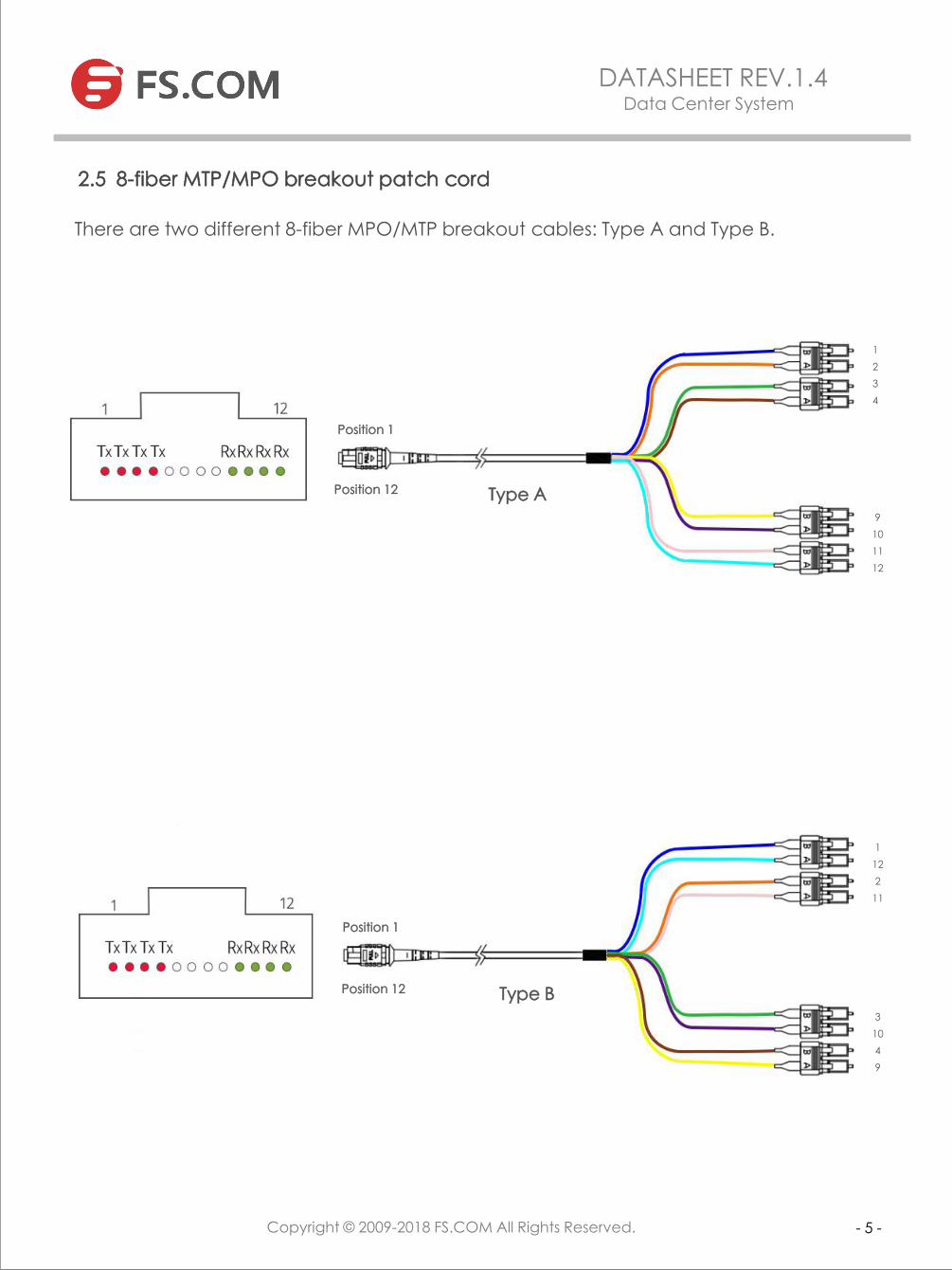
2.5 8-fiber MTP/MPO breakout patch cord
There are two different 8-fiber MPO/MTP breakout cables: Type A and Type B.
Position 1
Position 12 Type A
Type B
Position 1
Position 12
1234
9101112
1122
11
31049

1
12
2
11
3
10
4
9
5
8
6
7
+86 (755) 8300 3611 [email protected] www.fiberstore.com Page 4 of 4
Copyright © 2009-2015 Fiberstore
+86 (755) 8300 3611 [email protected] www.fiberstore.com Page 4 of 6
Copyright © 2009-2015 Fiberstore
+86 (755) 8300 3611 [email protected] www.fiberstore.com [email protected] FS.COM
Datasheet
DATASHEET REV.1.4 Data Center System
Copyright © 2009-2018 FS.COM All Rights Reserved. - 6 -
2.6 12-fiber MTP/MPO breakout patch cord
There are two different 12-fiber MPO/MTP breakout cables: Type A and Type B.
Position 1
Position 12 Type A
1
2
3
4
5
6
1
2
3
4
5
6
7
8
9
10
11
12
Type B
Position 1
Position 12

+86 (755) 8300 3611 [email protected] www.fiberstore.com Page 4 of 4
Copyright © 2009-2015 Fiberstore
+86 (755) 8300 3611 [email protected] www.fiberstore.com Page 4 of 6
Copyright © 2009-2015 Fiberstore
+86 (755) 8300 3611 [email protected] www.fiberstore.com [email protected] FS.COM
Datasheet
DATASHEET REV.1.4 Data Center System
Copyright © 2009-2018 FS.COM All Rights Reserved. - 7 -
2.7 20-fiber MTP/MPO breakout patch cord
There are three different 20-fiber MPO/MTP breakout cables: Type A, Type B and Type C.
Position 1
Position 24 Type A
Position 1
Position 24 Type B
23456789
101114151617181920212223
2113
10495867
14231522162117201819

1
2
3
4
5
6
7
8
9
10
11
12
13
14
15
16
17
18
19
20
21
22
23
24
+86 (755) 8300 3611 [email protected] www.fiberstore.com Page 4 of 4
Copyright © 2009-2015 Fiberstore
+86 (755) 8300 3611 [email protected] www.fiberstore.com Page 4 of 6
Copyright © 2009-2015 Fiberstore
+86 (755) 8300 3611 [email protected] www.fiberstore.com [email protected] FS.COM
Datasheet
DATASHEET REV.1.4 Data Center System
Copyright © 2009-2018 FS.COM All Rights Reserved. - 8 -
2.8 24-fiber MTP/MPO breakout patch cord
There are three different 24-fiber MPO/MTP breakout cables: Type A, Type B and Type C.
Type A
Position 1
Position 24
Position 1
Position 24 Type C
2
14
3
15
4
16
5
17
6
18
7
19
8
20
9
21
10
22
11
23

1
13
2
14
3
15
4
16
5
17
6
18
7
19
8
20
9
21
10
22
11
23
12
24
1
12
2
11
3
10
4
9
5
8
6
7
13
24
14
23
15
22
16
21
17
20
18
19
+86 (755) 8300 3611 [email protected] www.fiberstore.com Page 4 of 4
Copyright © 2009-2015 Fiberstore
+86 (755) 8300 3611 [email protected] www.fiberstore.com Page 4 of 6
Copyright © 2009-2015 Fiberstore
+86 (755) 8300 3611 [email protected] www.fiberstore.com [email protected] FS.COM
Datasheet
DATASHEET REV.1.4 Data Center System
Copyright © 2009-2018 FS.COM All Rights Reserved. - 9 -
Type C
Type B
Position 1
Position 24
Position 1
Position 24
Page 5 of 6
Copyright © 2009-2015 Fiberstore Copyright © 2009-2015 Fiberstore
[email protected] FS.COM
Datasheet
DATASHEET REV.1.4 Data Center System
Copyright © 2009-2018 FS.COM All Rights Reserved.
- 10 -
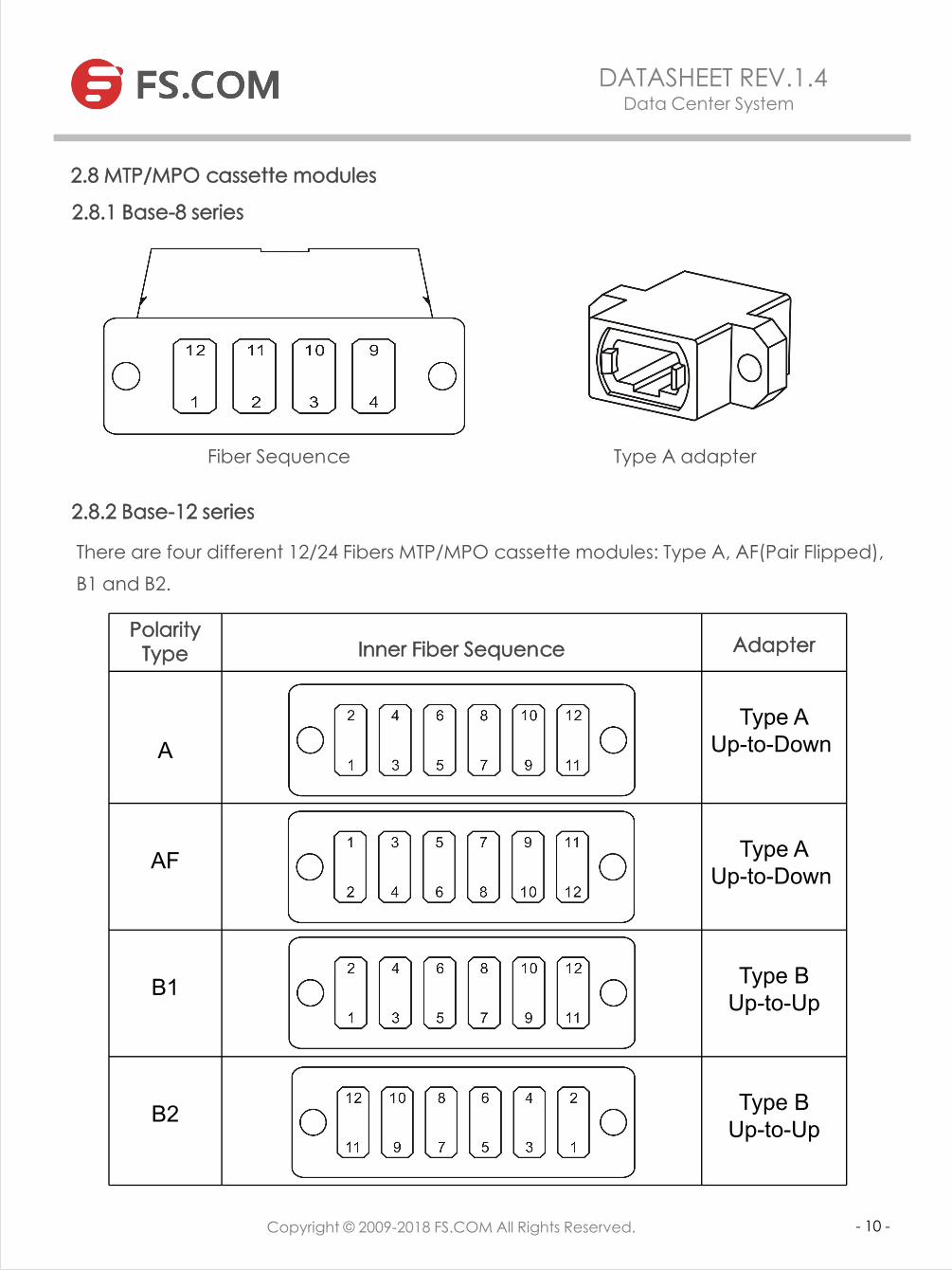
2.8 MTP/MPO cassette modules
2.8.1 Base-8 series
2.8.2 Base-12 series
There are four different 12/24 Fibers MTP/MPO cassette modules: Type A, AF(Pair Flipped), B1 and B2.
Fiber Sequence Type A adapter
Polarity Type Inner Fiber Sequence Adapter
AType A
Up-to-Down
AF Type AUp-to-Down
B1 Type BUp-to-Up
B2 Type BUp-to-Up

Copyright © 2009-2015 Fiberstore Copyright © 2009-2015 Fiberstore
Datasheet
Copyright © 2009-2018 FS.COM All Rights Reserved. - 11 -
DATASHEET REV.1.4 Data Center System
2.8.3 Base-24 series
There are two different 24 Fibers MTP/MPO cassette modules: Type A, and AF(Pair Flipped).
Polarity Type Inner Fiber Sequence Adapter
A Type AUp-to-Down
AF Type AUp-to-Down

Copyright © 2009-2015 Fiberstore Copyright © 2009-2015 Fiberstore
Datasheet
Copyright © 2009-2018 FS.COM All Rights Reserved. - 12 -
DATASHEET REV.1.4 Data Center System
3. Array polarity systems
All array connectivity methods have the same goal: to create an optical path from the transmit port of one device to the receive port of another device. Different methods to accomplish this goal may be implemented; however these different methods may not be interoperable. Any connectivity method requires a specific combination of components to maintain polarity. Some of the components may be common to other connectivity methods. The components associated with the three illustrated array polarity methods A, B and C are given in below tables.
Table 1 – Summary of components used for duplex signals
Connectivitymethod
Array connectorcable Type
Array adapterType Duplex patch cord type
A A A One A-to-B & one A-to-A per duplex channel
B B B A-to-B
C C A A-to-B
Table 2 – Summary of components used for parallel signals
Connectivitymethod
Array connectorcable Type
Array adapterType Array patch cord type
A A A One Type A & one Type B
B B B Type B

Copyright © 2009-2015 Fiberstore Copyright © 2009-2015 Fiberstore
Datasheet
Copyright © 2009-2018 FS.COM All Rights Reserved. - 13 -
DATASHEET REV.1.4 Data Center System
3. 1 Connectivity Method A
3.1.1 Connectivity Method A for duplex signals
Note: If you don't want an A-to-A patch cord used, a TypeAF MTP/MPO cassette is needed, as shown below:
A-to-B Patch Cord A-to-A Patch Cord
Type A Type AType A
A-to-B Patch Cord A-to-B Patch Cord
Type A Type AFType A
3.1.2 Connectivity Method A for parallel signals
Type A
Type A Type A
Type A Type B

Copyright © 2009-2015 Fiberstore Copyright © 2009-2015 Fiberstore
Copyright © 2009-2018 FS.COM All Rights Reserved. - 14 -
DATASHEET REV.1.4 Data Center System
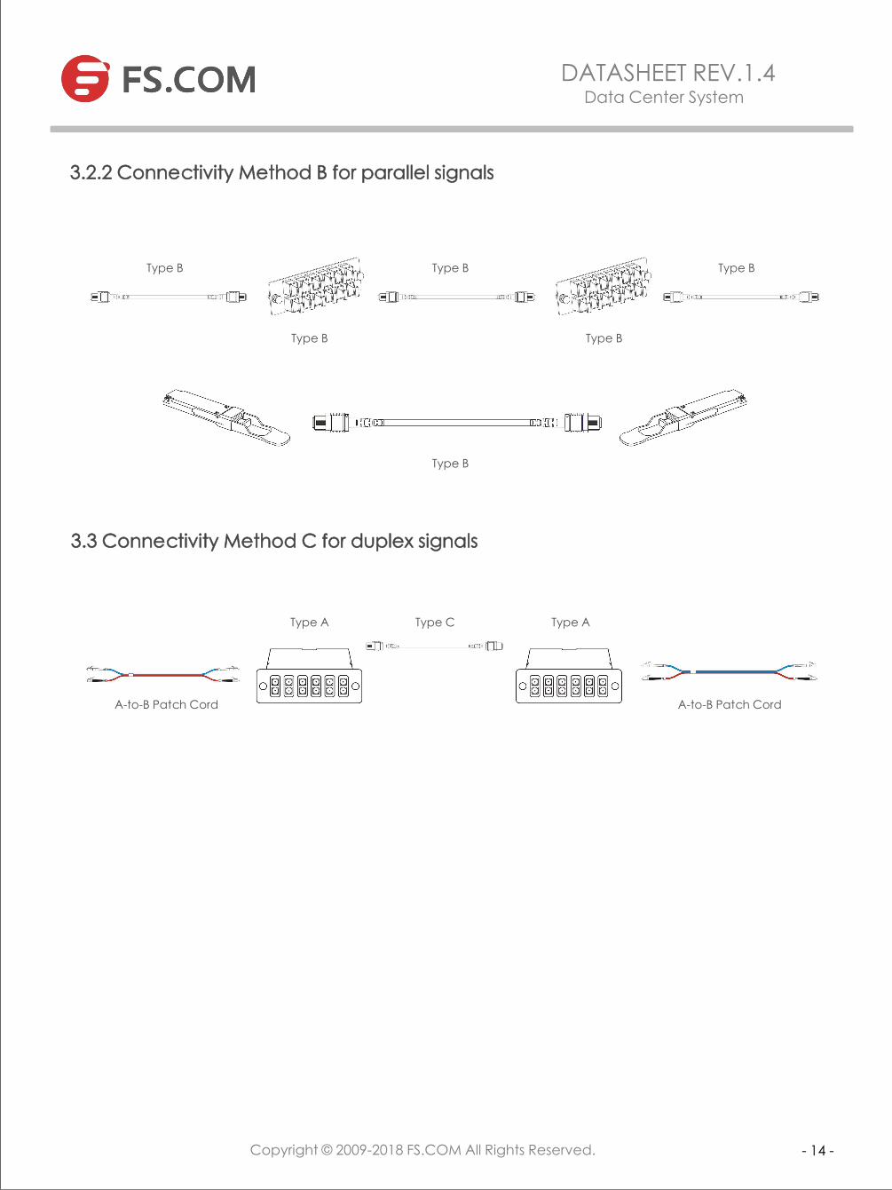
3.2 Connectivity Method B
3.2.1 Connectivity Method B for duplex signals
The Key Up to Key Up (method B) does not support Singlemode with standards compliant connector endfaces.
A-to-B Patch Cord A-to-B Patch Cord
Type BType A Type A
Note: The transmission of the signal is P1 in and P12 out.
Type B1 Type B2
A-to-B Patch Cord A-to-B Patch Cord
Note: The transmission of the signal is P1 in and P1 out.
Base-8 MTP/MPO cassette used for 10G to 40G/100G migration with Method B.
Type B
A-to-B Patch Cord
Type B
Copyright © 2009-2015 Fiberstore Copyright © 2009-2015 Fiberstore
Copyright © 2009-2018 FS.COM All Rights Reserved. - 14 -
DATASHEET REV.1.4 Data Center System
3.3 Connectivity Method C for duplex signals
3.2.2 Connectivity Method B for parallel signals
Type B
Type B Type B
Type B Type B
Type B
A-to-B Patch Cord A-to-B Patch Cord
Type A Type AType C
Copyright © 2009-2015 Fiberstore Copyright © 2009-2015 Fiberstore
Datasheet
Copyright © 2009-2018 FS.COM All Rights Reserved. - 15 -
DATASHEET REV.1.4 Data Center System
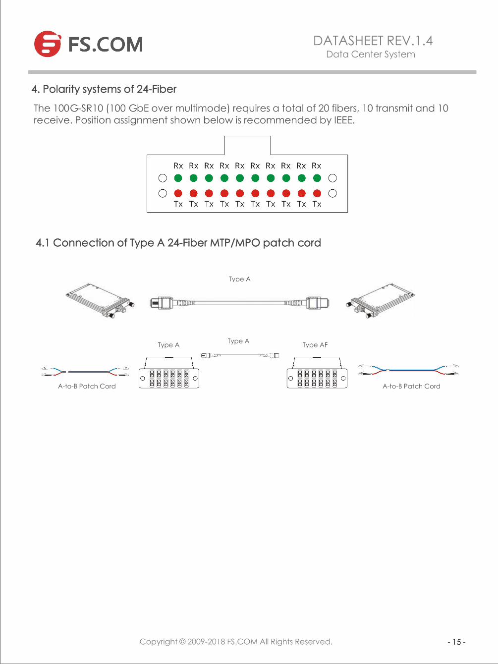
4.1 Connection of Type A 24-Fiber MTP/MPO patch cord
A-to-B Patch Cord A-to-B Patch Cord
Type A Type AFType A
4. Polarity systems of 24-Fiber
The 100G-SR10 (100 GbE over multimode) requires a total of 20 fibers, 10 transmit and 10 receive. Position assignment shown below is recommended by IEEE.
Type A

Europe (United Kingdom)Third Floor 207 Regent StreetLondon, W1B 3HHUnited KingdomTel: +44 (20) 3868 2768
Europe (Germany)Building 7, NOVA Neufahrn Gewerbepark, Am Gfild 7, 85375, Neufahrn bei Freising, Munich GermanyTel: +49 (0) 89 414176412
North America (United States)820 SW 34th Street Bldg W7 Suite HRenton, WA 98057United StatesTel: +1 (877) 205 5306
Asia (China)F3 Building 6/F, Optics Valley Software Park, Donghu Hi-Tech Development Zone, Wuhan, Hubei, ChinaTel: +86 (027) 87639823
Copyright © 2009-2015 Fiberstore Copyright © 2009-2015 Fiberstore
Datasheet
Addresses, phone number and fax number also have been listed at www.fs.com. Please e-mail us at [email protected] or call us for assistance.
All statements, technical information, and recommendations related to the products here are based upon information believed to be reliable or accurate. However, the accuracy or completeness thereof is not guaranteed, and no responsibil ity is assumed for any inaccuracies. Please contact FS for more information.
Contact Us
- 16 -
DATASHEET REV.1.4 Data Center System
Copyright © 2009-2018 FS.COM All Rights Reserved.