Embed Size (px)
Citation preview

Understanding controls on the performance of engineered barrier systems in repositories for high-level radioactive waste and spent fuel Report: SC060055

The Environment Agency is the leading public body protecting and improving the environment in England and Wales.
It’s our job to make sure that air, land and water are looked after by everyone in today’s society, so that tomorrow’s generations inherit a cleaner, healthier world.
Our work includes tackling flooding and pollution incidents, reducing industry’s impacts on the environment, cleaning up rivers, coastal waters and contaminated land, and improving wildlife habitats.
This report is the result of research commissioned and funded by the Environment Agency’s Science Programme.
Published by: Environment Agency, Rio House, Waterside Drive, Aztec West, Almondsbury, Bristol, BS32 4UD Tel: 01454 624400 Fax: 01454 624409 www.environment-agency.gov.uk ISBN 978-1-84911-199-7 © Environment Agency – September 2010 All rights reserved. This document may be reproduced with prior permission of the Environment Agency. The views and statements expressed in this report are those of the author alone. The views or statements expressed in this publication do not necessarily represent the views of the Environment Agency and the Environment Agency cannot accept any responsibility for such views or statements. This report is printed on Cyclus Print, a 100% recycled stock, which is 100% post consumer waste and is totally chlorine free. Water used is treated and in most cases returned to source in better condition than removed. Further copies of this report are available from our publications catalogue: http://publications.environment
Author(s): A. Bond, M.J. Egan, R. Metcalfe, P.Robinson, G. Towler Dissemination Status: Publicly available Keywords: Radioactive waste, Engineered Barrier System, Repository, Illustrative calculations Research Contractor: Quintessa Limited, The Hub, 14 Station Road, Henley-on-Thames, Oxon. RG9 1AY Environment Agency’s Project Manager: David Copplestone, Richard Fairclough House, Warrington, WA4 1HT. Project Number: SC060055 Product Code:SCHO0910BSZE-E-E
-agency.gov.uk or our National Customer Contact Centre: 08708 506506 E: [email protected].
ii Understanding controls on the performance of EBS in HLW / SF repositories

Evidence at the Environment Agency Evidence underpins the work of the Environment Agency. It provides an up-to-date understanding of the world about us, helps us to develop tools and techniques to monitor and manage our environment as efficiently and effectively as possible. It also helps us to understand how the environment is changing and to identify what the future pressures may be.
The work of the Environment Agency’s Evidence Directorate is a key ingredient in the partnership between research, policy and operations that enables the Environment Agency to protect and restore our environment.
The Research & Innovation programme focuses on four main areas of activity:
• Setting the agenda, by providing the evidence for decisions;
• Maintaining scientific credibility, by ensuring that our programmes and projects are fit for purpose and executed according to international standards;
• Carrying out research, either by contracting it out to research organisations and consultancies or by doing it ourselves;
• Delivering information, advice, tools and techniques, by making appropriate products available
Miranda Kavanagh
Director of Evidence
Understanding controls on the performance of EBS in HLW / SF repositories iii

Executive summary The Environment Agency needs to understand what influences the performance of a geological repository for high-level radioactive waste (HLW) and spent fuel (SF). This project set out to:
• understand and record the main controls on the groundwater pathway in some repository designs for HLW and SF disposal, focusing on the role of the engineered barrier system (EBS).
• comment on implications for waste form design, waste packaging and repository design.
The primary aim of this project was to summarize and analyse existing knowledge on processes that could influence the performance of an EBS and hence the long-term safety performance of a repository. The work was divided into two phases:
• devising an approach to analysing key controls on EBS performance;
• carrying out the analysis.
In the first phase, members of Quintessa’s project team defined a small number of reference designs (engineered barrier components) for a possible HLW and SF repository in the UK. A general approach to analysing controls on the performance of these designs was proposed, with both qualitative and quantitative components. An expert workshop was convened to discuss and refine the reference designs and this analysis approach. The experts concluded that published descriptions of disposal concepts would need to be simplified to render key controls on performance amenable to analysis. It was also recommended that the implications of building the waste disposal systems in different hydrogeochemical environments should be analysed.
The project’s second phase is the main focus of this report; notes of the expert workshop in the first phase are given in Appendix A. In this second phase a top-down approach was followed, consisting of:
• a literature review of concepts proposed by radioactive waste management programmes throughout the world;
• identification of representative disposal concepts, to illustrate the range of controls on EBS performance;
• review of safety functions attributed to barrier components in these concepts by radioactive waste management programmes across the world;
• identification of groups of features, events and processes (FEPs) that describe these safety functions and threats to these safety functions;
• an audit of these FEPs against the Nuclear Energy Agency’s international FEP list (NEA, 2000), to check that all major performance controls had been identified, and to identify links between FEPs in the NEA list and each group of FEPs derived from the safety function analysis;
• simple calculations using the GoldSim™ code to explore the significance of each of these FEPs as controls on the performance of barrier components;
• using the results of the simple calculations to guide the grouping of the FEPs in terms of underlying controls.
iv Understanding controls on the performance of EBS in HLW / SF repositories
The following representative disposal concepts were defined:
• shorter-lived waste package/overpack – clay buffer - hard fractured rock;
• longer-lived waste package/overpack – clay buffer - hard fractured rock;
• shorter-lived waste package/overpack – clay buffer – mudrock;
• shorter-lived waste package/overpack – cement buffer – mudrock;
• shorter-lived waste package/overpack – no buffer – mudrock;
• shorter-lived waste package/overpack – no buffer - bedded evaporite
The results of the literature review and calculations were used to identify the following key controls on EBS performance:
(1) chemical stability of engineered barriers;
(2) physical stability of engineered barriers;
(3) chemical environment of the EBS;
(4) groundwater flow characteristics;
(5) deformation characteristics of the host rock;
(6) waste characteristics;
(7) transport characteristics in the host rock;
(8) structure of the host rock;
(9) thermal conditions in the geosphere;
(10) thermal conditions in the EBS;
(11) radioactive decay and in-growth.
Each of these controls can be mapped to one or more FEPs from the NEA’s FEP list (NEA, 2000), which can in turn be mapped to the safety functions that correspond to each analysed disposal concept. However, the relative importance of these different controls and their overall impact upon safety will depend upon:
• site-specific characteristics;
• the detailed nature of the concept to be implemented;
• the detailed repository design;
• implementation of the repository design.
Furthermore, the performance required of an EBS depends not only upon technical issues connected with the EBS itself, but also upon the regulatory context and the characteristics of the surrounding geosphere, which were outside the project’s scope.
An important implication for EBS design is that it must meet regulatory requirements by working together with the geological environment in which it is to be emplaced. Thus, in the absence of information about the regulatory context and specific geological environment where a repository is to be sited, it is not possible to determine the optimum waste form, waste packaging and repository design. Conversely, it is quite conceivable that more than one design could achieve adequate performance in any particular geological environment.
Understanding controls on the performance of EBS in HLW / SF repositories v

The calculations show that the extent to which any radionuclide is able to migrate from the EBS is controlled by the half-life of the radionuclide, its chemical properties (principally whether sorbing or non-sorbing) and physical and chemical properties of the barriers. For spent fuel the buffer and backfill are more important barriers to contaminant transport for radionuclides that are strongly sorbed onto the buffer and backfill materials than for unsorbed radionuclides (although the buffer and backfill may also have important roles in radionuclide-independent functions such as protecting the waste canister). For long-lived and poorly sorbed radionuclides such as Iodine-129 the buffer and backfill act to delay release rather than reduce the flux from the EBS; the key role of the buffer and backfill in these cases is to protect the canister for as long as is required.
vi Understanding controls on the performance of EBS in HLW / SF repositories

Acknowledgements The following participants in the expert workshop are gratefully acknowledged: Dr Paul Abraitis, Mr Ian Barraclough, Dr David Copplestone, Dr Susan Duerden, Dr Gavin Thomson, Dr Roger Yearsley (Environment Agency), Dr Sam King (Nuclear Decommissioning Authority – Radioactive Waste Management Directorate), Dr Peter Jackson (Serco Assurance), Professor Francis Livens (CoRWM), Professor Stuart Lyon (Manchester University), Dr Michael Ojovan (Sheffield University), Dr Joe Small (National Nuclear Laboratory).
Dr David Bennett of Terrasalus wrote much of Sections 3 and 4 under sub-contract to Quintessa.
Understanding controls on the performance of EBS in HLW / SF repositories vii

Contents 1 Introduction 1
2 Approach 2
3 Identification of example disposal concepts 3 3.1 Aims of disposal concept identification 3 3.2 Approach to defining disposal concepts 3 3.3 Geological environments in England and Wales 4 3.4 Disposal concepts 7 3.5 Reasons for proposal of disposal concepts 9 3.6 Components of the EBS in each concept given in Section 3.4 10 3.7 Simplified classification of concepts and geological environments 14
4 Discussion of safety functions 20
5 FEP analysis 28 5.1 Key issues/controls 28 5.2 Summary of key issues/controls for different disposal concepts and
environments 44 5.3 FEP audit 50
6 Assessment and implications 53 6.1 Conceptual models 53 6.2 Calculations 57 6.3 Implementation 60 6.4 Results 64
7 Discussion of controls on repository performance 82 7.1 Differences between HLW and SF 82 7.2 Implications of whole repository upscaling 83 7.3 Key controls and the relationship to FEPs 85 7.4 Characteristics of concepts that affect the relative importance of controls 87 7.5 Interactions between disposal system components 91 7.6 Other controls on repository performance 93 7.7 Implications for other wastes 94 7.8 Implications for co-location 95 7.9 Knowledge limitations 95
8 Summary and conclusions 96
References 98
viii Understanding controls on the performance of EBS in HLW / SF repositories
Glossary and List of abbreviations 103
Appendix A 105
1 Introduction 107
2 Summary of the workshop 108
3 Presentations 109 3.1 Introduction to the project 109 3.2 Workshop briefing 110
4 Record of discussions 112 4.1 Inputs from Discussion Group 1 112 4.2 Inputs from Discussion Group 2 113 4.3 Inputs from Discussion Group 3 113 4.4 Plenary discussion 114
5 Next steps 116
Appendix A References 119
Appendix B FEP Audit 120
Appendix B References 128
Appendix C Selection of representative radionuclides 193
Appendix C References 200 Table 3.1 UK geological environments identified by Baldwin et al. (2008). 5 Table 3.2 Comparison between the geological environments identified in Metcalfe and Watson (2009). 6 Table 3.3 Disposal concepts identified by Baldwin et al. (2008). 8 Table 3.4 Main distinguishing reasons for development of each disposal concept, based on published literature. 11 Table 3.5 Main components of EBS in each of the disposal concepts listed in Section 3.4. 12 Table 3.6 Geological environments within which disposal concepts could be employed. 13 Table 3.7 Summary of simplified combinations of geological environments and EBS considered in subsequent
sections of the report 18 Table 4.1 Safety functions and key controls on performance of various disposal concept/geological environment
combinations as identified by radioactive waste disposal programmes throughout the world 22 Table 5.1 Corrosion processes (Bennett and Gens 2008) 32 Table 5.2 Interaction matrix for KBS-3 type disposal concept including hard fractured rock host rock and clay
buffer. 46 Table 5.3 Interaction matrix for disposal concepts including mudrock host rock and clay buffer. 47 Table 5.4 Interaction matrix for disposal concepts including mudrock host rock and supercontainer with cement
buffer. 48 Table 5.5 Interaction matrix for disposal concepts including evaporite host rock and salt backfill. 49 Table 5.6 Summary of NEA FEPs from screened list in Table B.2 that are not relevant to any disposal
concepts. 52 Table 6.1 Data used in the calculations. 63 Table 6.2 Probabilistic Density Function (PDF) Data. 76 Table 7.1 Summary of the regions within a repository to which the calculation variants in Section 6 apply. 84 Table 7.2 Subset of FEPs from the NEA (2000) International FEP list that could exert an influence on
repository performance. 86 Table 7.3 Characteristics of disposal concepts that affect key underlying controls on repository performance
given in Section 7.3. 88 Table A.1 Details of workshop participants. 108
Understanding controls on the performance of EBS in HLW / SF repositories ix

Table A.2 Summary of simplified combinations of geological environments and EBS to be evaluated in Phase 2 of the project, based in part on discussions at the workshop on 7 May 2008. 118
Table B.1 NEA’s FEP list (from NEA, 2000) and the application of each FEP in this list during the present audit. 120
Table B.2 FEPs from the NEA’s FEP list (NEA, 2000) used in the audit and their potential impacts on safety functions. 125
Table B.3-6 Comparison between the FEPs and FEP groups 129 Table C.1 Summary of characteristics of radionuclides in the 2007 UK HLW inventory (Defra and NDA, 2008). 195 Figure 5.1 Finite element modelling of the potential effect on a SF waste disposal canister and surrounding buffer
of shearing cause by a post-glacial earthquake (SKB 2006a). 34 Figure 5.2 Granular backfill emplacement following pre-2006 Swedish backfill concept in underground laboratory
at Äspö (left), and revised Swedish backfill emplacement concept involving placement of pre-formed bentonite blocks (right). 38
Figure 5.3 Factors that may control the performance of HLW glass waste forms in a repository (after Grambow et al. 2008). 43
Figure 6.1 Conceptual model for hard fractured host rock with KBS-3V type disposal (Concept 1), with potential radionuclide release pathways indicated by red arrows. 54
Figure 6.2 Conceptual model for mudrock host rock with clay buffer disposal (Concept 2), with potential radionuclide release pathways indicated by red arrows. 55
Figure 6.3 Conceptual model for mudrock host rock with supercontainer and cement buffer disposal (Concept 3), with potential radionuclide release pathways indicated by red arrows. 56
Figure 6.4 Conceptual model for evaporite host rock with salt backfill (Concept 4), with potential radionuclide release pathway indicated by a red arrow. 56
Figure 6.5 Generic discretisation used in the GoldSim calculations here. The red lines show the flow paths modelled. 62
Figure 6.6 Concept 1: ratio of the cumulative flux out of the canister to the initial inventory for the pinhole case. 66 Figure 6.7 Concept 1: ratio of the cumulative flux out of the canister to the initial inventory for the buffer erosion
and canister corrosion case. 66 Figure 6.8 Concept 1: ratio of the cumulative flux out of the buffer to the cumulative flux into the buffer for the
pinhole variant. 67 Figure 6.9 Concept 1: ratio of the cumulative flux out of the buffer to the cumulative flux into the buffer for the
canister shear variant. 67 Figure 6.10 Concept 1: ratio of the cumulative flux out of the backfill to the cumulative flux into the backfill for the pinhole
variant. 68 Figure 6.11 Concept 2: ratio of the cumulative flux out of the canister to the initial inventory for the base case. 69 Figure 6.12 Concept 2: ratio of the cumulative flux out of the buffer to the cumulative flux into the buffer for the base
case. 69 Figure 6.13 Concept 2: ratio of the cumulative flux out of the backfill to the cumulative flux into the backfill for the base
case. 70 Figure 6.14 Concept 3: ratio of the cumulative flux out of the canister to the initial inventory for the base case. 71 Figure 6.15 Concept 3: ratio of the cumulative flux out of the buffer to the cumulative flux into the buffer for the base
case. 71 Figure 6.16 Concept 3: ratio of the cumulative flux out of the backfill to the cumulative flux into the backfill for the base
case. 72 Figure 6.17 Concept 4: ratio of the cumulative flux out of the canister to the initial inventory for the base case. 73 Figure 6.18 Concept 4: ratio of the cumulative flux out of the canister to the initial inventory for the early canister
corrosion variant. 74 Figure 6.19 Concept 4: ratio of the cumulative flux out of the buffer to the cumulative flux into the buffer the base case.74 Figure 6.20 Concept 4: ratio of the cumulative flux out of the buffer to the cumulative flux into the buffer the canister
corrosion variant. 75 Figure 6.21 Probability density functions for canister failure time and scaling factor used in the probabilistic calculations.76 Figure 6.22 Concept 1 pinhole variant: canister failure time probabilistic results for the ratio of the cumulative flux out of
the canister to the initial inventory for I-129. 77 Figure 6.23 Concept 1 pinhole variant: canister failure time probabilistic results for the ratio of the cumulative flux out of
the canister to the initial inventory for C-14. 77 Figure 6.24 Concept 1 pinhole variant: fuel dissolution rate probabilistic results for the ratio of the cumulative flux out of
the canister to the initial inventory for I-129. 78 Figure 6.25 Concept 1 pinhole variant: solubility limit probabilistic results for the ratio of the cumulative flux out of the
canister to the initial inventory for U-235. 78 Figure 6.26 Concept 1 pinhole variant: flow rate probabilistic results for the ratio of the cumulative flux out of the buffer
to the cumulative flux into the buffer for I-129. 80 Figure 6.27 Concept 1 pinhole variant: flow rate probabilistic results for the ratio of the cumulative flux out of the buffer
to the cumulative flux into the buffer for C-14. 80
x Understanding controls on the performance of EBS in HLW / SF repositories
1 Introduction In England and Wales, the Environment Agency is responsible under the Environmental Permitting (England and Wales) Regulations 2010 (EPR 10) for permitting deep geological disposal of higher activity wastes. Higher activity wastes include intermediate-level radioactive wastes (ILW) and high-level radioactive wastes (HLW) and some low-level radioactive waste (LLW) unsuitable for near-surface disposal. The inventory for disposal may also include spent nuclear fuel (SF), uranium and plutonium should these be declared as wastes in the future. The Environment Agency has powers under the EPR 10 to implement staged regulation of deep geological disposal. Staged regulation provides regulatory control from start of site investigation, through construction and operation, and eventually to closure. Before the start of each development stage, the developer will be required to submit to an environmental safety case to support an application for regulatory approval to proceed. Over time, the level of detail in the environmental safety case will increase as more information becomes available, for example, from geological investigations and supporting research and development studies. Currently, the Environment Agency has a voluntary agreement to provide regulatory scrutiny of the scientific and technical work on geological disposal undertaken by the Nuclear Decommissioning Authority's (NDA) Radioactive Waste Management Directorate (RWMD). This allows regulatory oversight before the start of the any formal regulatory process. The aim of this work was to support the Environment Agency’s understanding of the key controls on the performance of the engineered barrier system (EBS) of a geological repository for HLW and SF. Specifically the goals of the project were to:
• understand and document controls on the groundwater pathway of some repository designs for HLW and SF disposal, focusing on the role of the EBS to limit release into the environment;
• comment on implications for waste form design, waste packaging and repository design.
The work was divided into two phases:
i. The first phase involved devising an approach to assess key controls on EBS performance, based on a set of reference designs (engineered barrier components) for a possible HLW and SF repository in England and / or Wales. The aim was to define a set of reference cases for analysis in the second phase.
ii. The second phase involved running the analysis, to establish the importance of key barriers and how they work in combination to determine the overall long-term performance of the EBS considered. The phase included a commentary on uncertainties and implications for design optimisation and waste acceptance criteria.
The main activities in the first phase were preparing, convening and documenting an expert workshop and subsequently evaluating the workshop’s outcomes in the context of published literature and knowledge of the project team. Preparations involved reviewing published literature and developing topics for discussion. The workshop was attended by members of Quintessa’s project team and a panel of invited experts. A description of the workshop and its conclusions are given in Appendix A.
Understanding controls on the performance of EBS in HLW / SF repositories 1

2 Approach The project aimed to determine primarily how the engineered barriers in a geological repository for HLW/SF would influence the overall performance of the repository.
To develop an understanding of controls on long-term EBS performance, it is important to strike a balance between factors that can influence the function of individual engineered barriers and the way in which those barriers combine as a system (EBS) to isolate and contain radioactive waste. For example, too great a focus on individual barriers could divert attention and resources towards specific engineering problems rather than issues that are most important to overall design optimisation. However, if attention was focused solely on the overall system, simplifying assumptions necessary to support system-level understanding might obscure controlling issues and constraints associated with specific system components.
The Environment Agency covers England and Wales. Therefore it was only necessary to consider the disposal concepts that could work in the geological environments that are present in England and Wales.
Thus, the following steps were taken:
• identification of illustrative repository concepts that could be employed in England and Wales;
• qualitative and simple quantitative analysis of individual engineered barriers associated with these concepts and factors that influence performance;
• combination of component-level understanding to deduce generic implications for system-level safety performance.
The quantitative analysis focussed on transport of water and radionuclides through the EBS. Mechanical factors were discussed qualitatively.
The illustrative repository concepts were derived from concepts proposed in the UK and elsewhere, taking into account the variety of geological environments in England and Wales within which a repository could be constructed. Concepts were then classified according to the expected behaviour of the EBS and host rocks. This classification was used as a basis for deriving cases for a small number of numerical analyses to explore how components of these different EBS would work together to influence the performance of the overall repository.
2 Understanding controls on the performance of EBS in HLW / SF repositories

3 Identification of example disposal concepts
3.1 Aims of disposal concept identification At the time of writing, there has been relatively little work on the deep geological disposal of HLW/SF in the UK. Therefore, we explored concepts proposed in other countries as a basis for defining EBS features to be considered here. These concepts and the geological environments for which they are suitable are reviewed here.
The project focussed on the EBS (waste form, container/overpack, buffer) and its function in relation to the geological environment in which it is constructed, rather than other issues such as the transport of released radionuclides to the surface.
Other requirements for the project were:
• The project must not prejudge outcomes of site selection or its implications for repository design.
• A range of repository/EBS concepts that might be developed in England and/or Wales should be considered.
• The focus should be on the post-closure safety case and aspects that could affect the performance of the long-term safety functions by engineered barriers.
• The main waste forms for consideration are HLW and SF, according to current inventory projections, although consideration should be given to changes in future wastes (such as higher burn-up, alternative HLW blends).
• The implications of co-locating a repository for HLW and SF with one for ILW should be reflected in the analysis, but not be the main focus.
• The work should consider only the groundwater pathway and not other potential pathways, such as the gas pathway or human intrusion pathway.
3.2 Approach to defining disposal concepts The approach had four main steps:
• to review information on disposal concepts proposed by radioactive waste management programmes in other countries;
• to identify geological environments within which these concepts might be implemented;
• to identify which of these environments occur in England and/or Wales;
• to identify a set of disposal concept-geological environment combinations to illustrate the main controls on repository performance.
Two key literature sources for the first step were Metcalfe and Watson (2009) and Baldwin et al. (2008). The first of these documents was prepared for the Environment
Understanding controls on the performance of EBS in HLW / SF repositories 3

Agency in a separate project and identified technical issues associated with deep repositories in different geological environments. This document includes a qualitative assessment of how the characteristics of geological environments for a deep repository within England and Wales would impact upon the functioning of different kinds of EBS.
Baldwin et al. (2008) was published by the NDA and reviews geological disposal options for HLW and SF. The report also evaluates the extent to which these options might be suitable for the geological environments in the UK.
Metcalfe and Watson (2009) and Baldwin et al. (2008) together contained much of the information about disposal concepts required for the project. It was considered appropriate for this project to use Baldwin et al. (2008) because:
• it is a summary of work carried out in radioactive waste disposal programmes outside the UK, combined with a general appraisal of the wide-ranging geological environments that occur within the UK;
• it does not make recommendations on implementation in the UK of any of the reviewed disposal concepts.
However, it would have been inappropriate to use information about disposal concepts and geological environments in Metcalfe and Watson (2009) and Baldwin et al. (2008) without modification, since these reports were prepared for different purposes to ours. Therefore, Metcalfe and Watson (2009) and Baldwin et al. (2008) were used as a starting point and adapted by:
• summarizing the geological environments described in Baldwin et al. (2008);
• summarizing the disposal concepts described in Baldwin et al. (2008);
• checking that the concepts adequately cover the range of concepts proposed in the UK and other countries;
• determining whether all or some of these concepts would be appropriate for geological environments that occur in England and/or Wales, as described in Metcalfe and Watson (2009);
• listing the components of EBS in those concepts that could be applied in England and/or Wales;
• simplifying the classification of the EBS and geological environments to:
- remove duplication of important features and processes that might impact upon repository performance;
- include only the most cost-effective options with no implications for performance;
• identifying what aspects of these EBS components might vary in each concept-geological environment combination within which they might be applied, taken from the simplified classification scheme described above.
3.3 Geological environments in England and Wales The UK geological environments identified by Baldwin et al. (2008) are summarized in Table 3.1. Classification of the environments is based primarily on their geotechnical characteristics (“rock strength”) and groundwater flow/solute transport characteristics. The nature of the rock sequence that overlies the host rock is not used to distinguish
4 Understanding controls on the performance of EBS in HLW / SF repositories

the geological environments. Thus, any of the Geological Environments G1, G2, G3 and G4 may have host rocks that are overlain by low or high-permeability sedimentary rocks. Depending upon the geological setting of the site, these different overlying rocks could influence the flux of groundwater through the host rock and the rate at which this flux responds to environmental changes. For example, groundwater fluxes in a hard fractured host rock (here taken to include crystalline rocks such as granite and metamorphic rocks such as gneiss) overlain by lower permeability rocks might respond more slowly to climate-induced changes in recharge than would a similar hard fractured rock overlain by higher permeability rocks. The permeability of the overlying rocks might also influence the migration of any gas that is evolved from a repository, although this topic is outside the scope of the work reported here.
Table 3.1 UK geological environments identified by Baldwin et al. (2008).
No General Description Host rock Overlying rocks Low permeability sedimentary rock formations G1 Stronger rocks with very low flow
of likely saline waters Crystalline rock High permeability sedimentary rock formations Low permeability sedimentary rock formations High permeability sedimentary rock formations
Crystalline rock
Crystalline rock to surface G2
Stronger rocks with higher water flow; probably relatively fresh water
Carbonate Sedimentary rock formations (permeability unspecified) Low permeability sedimentary rock formations
Indurated low permeability sedimentary rock formation
High permeability sedimentary rock formations G3
Weaker rocks with no effective flow and relatively saline waters in pores (transport is dominated by diffusion with no advective flow)
Plastic low permeability sedimentary rock formation
Sedimentary rock formations (permeability unspecified)
Low permeability sedimentary rock formations G4
Weaker rocks with very low water flow and relatively saline waters in pores (there is some advective flow)
Indurated low permeability sedimentary rock formation
High permeability sedimentary rock formations
G5 Evaporite formations: plastic, with no water flow and little accessible water (brine) content
Evaporites - salt dome & bedded salt
Sedimentary rock formations (permeability unspecified)
The geological environments within England and/or Wales that might plausibly host a deep geological repository for HLW and/or SF have been identified in Metcalfe and Watson (2009). It is appropriate to compare these environments with those identified in Baldwin et al. (2008), to:
• determine the extent to which the environments in Baldwin et al. (2008) occur within these parts of the UK;
• establish whether there are other geological environments that occur within England and/or Wales which are not covered by those identified in Baldwin et al. (2008).
The two sets of geological environments are compared in Table 3.2.
Understanding controls on the performance of EBS in HLW / SF repositories 5

Table 3.2 Comparison between the geological environments identified in Metcalfe and Watson (2009), here numbered 1 to 9, and those identified in
Baldwin et al. (2008), here denoted G1 to G5.
G1 G2 G3 G4 G5
General rock properties
Stronger rocks
Stronger rocks, greater
water flow Weaker rocks Weaker
rocks
Evaporite formations, plastic, little accessible
water
Probable porewater salinity Saline Relatively
fresh Relatively
saline Relatively
saline Brine
Water flow characteristics Very little flow Greater flow No effective
flow Very little
flow No effective
flow
Main transport mechanisms
Some advection Advection Diffusion, no
advection Some
advection Diffusion, no
advection
Geo
logi
cal E
nviro
nmen
ts in
Bal
dwin
et a
l. (2
008)
Host rock Crystalline rock
Crystalline rock or
Carbonate
Indurated low permeability or Plastic low permeability sedimentary
Indurated low
permeability sedimentary
Evaporites - salt dome and
bedded
Geological Environments in Metcalfe and Watson
(2009)
1 Hard, fractured rock to surface Equivalent
2
Hard, fractured rock overlain by relatively high-permeability sedimentary rocks in which advective transport dominates
Equivalent, although definition of 2 includes possibility for saline water
3
Hard, fractured rock overlain by sedimentary rocks containing at least one significant low- permeability unit in which diffusion dominates solute transport
Equivalent
4 Bedded evaporite host rock
4 equivalent to bedded evaporite sub-type of G5
5
Siliceous sedimentary host rock 5 similar, but
different host rock
5 similar, but different host rock
5 similar if siliceous host rock of Geological Environment 5 is weak
6 Mudstone host rock Equivalent 7 Plastic clay host rock Equivalent
8 Carbonate host rock
8 similar if has low K, relatively high porosity, solute transport probably diffusion- dominated (8a sub-type)
8 similar if has moderate to high K, high porosity, fractures control flow (8c sub-type)
9 Non-evaporitic host rock with hypersaline groundwater
Geological Environment 9 of Metcalfe and Watson (2008) not represented explicitly in definitions of Geological Environments G1 to G4 of Baldwin et al. (2008)
Not equivalent
6 Understanding controls on the performance of EBS in HLW / SF repositories

From this table it is apparent that the classifications of geological environments in Baldwin et al. (2008) and Metcalfe and Watson (2009) are broadly similar, but there are differences reflecting the different purposes of these two reports:
• All the geological environments identified in Baldwin et al. (2008) occur within England and/or Wales.
• Most geological environments identified in Metcalfe and Watson et al. (2009) are the same as, or very similar to, at least one geological environment identified in Baldwin et al. (2008). The exception is Environment 9 in which a highly saline groundwater is combined with a non-evaporite host rock, which does not appear to be covered fully by Baldwin et al. (2008) who consider only ‘relatively saline’ or ‘saline’ water
• In the classification of Metcalfe and Watson et al. (2009), the groundwater/ porewater from any geological environment, apart from Environment 4 (bedded evaporite), could have a wide range of salinity, and could include brine (if the environment is combined with Environment 9). In contrast, the classification of Baldwin et al. (2008) includes groundwater/porewater salinity more explicitly in the definitions. Highly saline groundwater (i.e. brine) is only present in the evaporite host rock of Baldwin et al. (2008).
• Environment 8a of Metcalfe and Watson (2009) is similar to Environment G1 of Baldwin et al. (2008) based on geotechnical and hydrogeological criteria. However, the definition of Environment 8a includes a low-permeability limestone host rock which is not encompassed by the definition of Environment G1. Thus there may be differences in groundwater chemistry that have implications for EBS performance.
• Geological Environment 5 of Metcalfe and Watson (2009) includes a siliceous sedimentary host rock that is not exactly the same as any of the host rocks within the geological environments G1 to G5 of Baldwin et al. (2008). There are similarities between Environment 5 and Environments G1, G2 and G4. However, Environments G1 and G2 do not include siliceous sedimentary host rocks. Furthermore, Environment G4 is defined to have “weaker” sedimentary host rocks, whereas Environment 5 will most likely have “strong” sedimentary host rocks. The hydrogeological properties of the siliceous sedimentary host rock in Environment 5 will be similar to those of the crystalline host rocks of Environments G1 and G2. However, the geometries of the sedimentary and crystalline host rocks will probably be very different.
Definitions of the geological environments in Metcalfe and Watson (2009) include details of the rocks that overlie the host rock. The classification places much greater emphasis on the characteristics of groundwater flow through the host rocks than does the primary classification of Baldwin et al. (2008). These latter authors take into account the overlying rocks in subdivisions of the Geological Environments G1 to G3.
3.4 Disposal concepts Baldwin et al. (2008) described a variety of concepts applicable to UK geological environments, based on information from radioactive waste disposal projects internationally. The only significant solid HLW/SF geological disposal concept that was not considered is the one developed for Yucca Mountain in Nevada, USA. This concept is suitable for a geological environment that does not occur in the UK, namely
Understanding controls on the performance of EBS in HLW / SF repositories 7

unsaturated tuffaceous host rocks located within a desert environment. The disposal concepts identified by Baldwin et al. (2008) are summarized in Table 3.3.
The different concepts are distinguished principally by a combination of the barrier system employed, and the geometry of the barrier system.
Table 3.3 Disposal concepts identified by Baldwin et al. (2008). The classification of canisters into “long-lived” and “short-lived” varieties follows
these authors.
Key feature Variants Concept No.
Vertical borehole 1 In-tunnel (borehole) Horizontal borehole 2 Short-lived canister and buffer 3 In-tunnel (axial) Long-lived canister and buffer 4 Small working annulus 5 Small annulus + concrete buffer 6
In-tunnel (axial) with supercontainer
Large working annulus 7 Steel multi-purpose transport/storage/disposal containers (MPC) + bentonite backfill
8 Caverns with cooling, delayed backfilling
Steel or concrete/DUCRETE container + cement backfill 9
Mined deep borehole matrix 10 Hydraulic cage Around a cavern repository 11 Very deep boreholes 12
Concept 12 is not relevant to this project, which considers only mined repositories, and consequently is not considered further in this report.
Several variants of each concept in Table 3.3 can be suggested, and some variations could be implemented in more than one concept. For example, shorter-lived canisters (such as thick, carbon steel) or longer-lived canisters (such as copper with cast iron insert) could be used with Concept 1 or Concept 2. However, the range of concepts in Table 3.3 covers all the main barrier systems and geometries proposed and there would be no advantage in subdividing them in the absence of site-specific information.
The classification of Baldwin et al. (2008) distinguishes between concepts with “short-lived” canisters and concepts with “long-lived” canisters. However, the review by Metcalfe and Watson (2009) found no universally agreed lifespan that may distinguish between these two groups of canister. Typically “short-lived” canisters are deemed to provide containment for a few hundreds to thousands of years, whereas “long-lived canisters” are required to provide containment for tens of thousands to over 100,000 years and possibly until the end of the time considered by a safety assessment. Thus, the required lifetime for a so-called “short-lived” canister is not necessarily “short” in the commonly accepted sense. Consequently, classification of canisters into “short-lived” and “long-lived” types can be misleading. Furthermore, it is sometimes helpful to distinguish cases where waste canisters/overpacks alone can provide containment for a specified time period, from cases where it is adequate for the whole EBS to provide containment for this period.
For these reasons, Metcalfe and Watson (2009) adopted a slightly different terminology to Baldwin et al. (2008) and used:
8 Understanding controls on the performance of EBS in HLW / SF repositories

• “Longer-lived waste package/overpack” for a waste package (comprising a waste form and waste container, as defined by IAEA, 2003), or waste package in combination with an overpack, that is expected to provide containment for over 100,000 years, and potentially to the end of the period considered by any safety assessment.
• “Shorter-lived waste package/overpack” for any other waste package, or waste package in combination with an overpack, that is expected to provide some containment following repository closure, but for a shorter period (typically in the order of 100 to 1,000 years).
• “Higher-integrity EBS” for an entire EBS that is expected to provide containment for over 100,000 years, and potentially to the end of the period considered by any safety assessment.
• “Lower-integrity EBS” for an entire EBS that is expected to provide some containment following repository closure, but for a much shorter period than a “higher-integrity EBS” (typically in the order of 100 to 1,000 years).
This terminology is used henceforth in this report.
3.5 Reasons for proposal of disposal concepts A given radioactive waste disposal organisation will typically choose a particular disposal concept or concepts for a variety of reasons. Performance-related reasons are always very important, but there are normally additional reasons too, such as the practicality of constructing the concept in a particular geological environment, or the availability of suitable materials. The reasons will naturally provide pointers towards general controls on repository performance that are perceived by these organisations.
It is typically difficult to determine all the reasons why a particular radioactive waste disposal programme has developed/proposed a given disposal concept. Usually, the literature produced by such a programme presents a disposal concept and explains why it will meet the performance criteria required. From this literature the major reasons are obvious, but the detailed reasoning as to why it has been chosen is normally less clear. We deduced the main reasons for each of the concepts described in Section 3.4, using expert judgments based on a variety of published information. The main source used was Baldwin et al. (2008), which summarizes the main drivers for these disposal concepts. This information was augmented by judgments based on the literature listed in Table 4.1, concerning various radioactive waste management programmes. The main reasons deduced are summarized in Table 3.4. It should be noted that this table does not highlight every positive characteristic that every concept might have, but only those that are stated explicitly by the proponents of the concept or inferred by Quintessa to be major drivers in distinguishing between concepts. Where this table omits a particular reason for a concept, it does not necessarily imply that the concept would not show the advantageous behaviour implied by the omitted reason. Instead this omission means simply that the advantage is not typically cited explicitly as a specific reason for the concept being chosen. For example, Concepts 5, 6 and 7, which include supercontainers, are expected to prevent the release of an initial release fraction (IRF) as a pulse, but this function is not cited as a major driver for these concepts being proposed, and so is not marked as such in Table 3.4.
Understanding controls on the performance of EBS in HLW / SF repositories 9

3.6 Components of the EBS in each concept given in Section 3.4
The major components proposed for the EBS in each of the concepts outlined in Section 3.4 are tabulated in Table 3.5. In this table, major groupings of components are given as column headings (waste form, waste container, overpack/canister, buffer, shell, backfill, seals). Within each group, components consistent with the concept are listed. Typically just one component from each group would be present within any single implementation of the concept.
The choice of component in a given implementation of a concept would depend upon the site characteristics (especially the host geology), and design choice taking into account costs, availability of materials, access to manufacturing capabilities and so on. Different choices may be made for particular waste-forms and inventories.
However, whether site-specific characteristics or design choices dictate particular components is not clear-cut and will depend on the context of a particular programme. For example, in a very low-permeability host rock, it may be better to choose shorter-lived canisters; shorter-lived canisters are likely to be cheaper and a sufficiently low-permeability host rock makes longer-lived canisters unnecessary. However, it is conceivable that regulatory factors or a need to build public confidence could lead to ‘over-engineered’ longer-lived canisters being selected.
10 Understanding controls on the performance of EBS in HLW / SF repositories

Understanding controls on the performance of EBS in HLW / SF repositories 11
Table 3.4 Main distinguishing1 reasons for development of each disposal concept, based on published literature.
No Concept2M
inim
ize
EDZ3
Was
te p
lace
d in
rela
tivel
y un
dist
urbe
d ro
ck (b
eyon
d ac
cess
tunn
el E
DZ)
Pr
even
t rel
ease
of i
nitia
l rel
ease
fr
actio
n ( I
RF4 ) a
s pu
lse
Max
imiz
e us
e of
hor
izon
tally
ext
ensi
ve
host
rock
form
atio
n
Min
imis
e ex
cava
tion
volu
me
Max
imis
e st
abili
ty o
f ope
ning
s in
st
ress
fiel
d En
sure
qua
lity
of c
anis
ter/b
uffe
r co
nstr
uctio
n
Shie
ld w
aste
thro
ugho
ut e
mpl
acem
ent
Con
cret
e pa
ssiv
ates
met
al b
arrie
r co
mpo
nent
s En
hanc
e ea
se o
f em
plac
emen
t and
if
nece
ssar
y, re
trie
val
Ensu
re c
ompa
ct re
posi
tory
foot
prin
t
Faci
litat
ing
clos
ure
rapi
dly
(not
ne
cess
arily
at e
arly
tim
es) i
f des
ired
Enha
nced
shi
eldi
ng d
urin
g op
en p
erio
d
Dis
posa
l of u
nwan
ted
DU
5
Red
uce
wat
er fl
ux th
roug
h th
e re
posi
tory
1 In-tunnel (vertical borehole) *
2 In-tunnel (horizontal borehole)
*
3 In-tunnel (axial) with shorter-lived waste package/ overpack and buffer
4 In-tunnel (axial) with longer-lived waste package/ overpack and buffer
5 In-tunnel (axial) with supercontainer (small annulus)
6 In-tunnel (axial) with supercontainer (concrete buffer)
7 In-tunnel (axial) with supercontainer (large annulus)
8 Caverns with steel MPC6 (bentonite backfill)
9 Caverns with steel MPC or concrete/ DUCRETE7 CDC8 (cement backfill)
10 Mined deep borehole matrix
11 Hydraulic cage Note: *Only for longer-lived canisters
1 A given concept has been proposed for multiple reasons, many of which are common to other concepts. This table shows only those reasons for each concept that are distinct from those for other concepts. 2 This column gives only the key feature/title of each concept. 3 EDZ is an excavation damage zone. 4 IRF is the instantaneously released fraction. 5 DU is depleted uranium. 6 MPC refers to a multi-purpose storage container. 7 DUCRETE is concrete that contains depleted uranium. 8 CDC refers to concrete disposal casks.

Understanding controls on the performance of EBS in HLW / SF repositories
No Concept Waste
Form Waste
Container Overpack/Canister Buffer Shell Tunnel Backfill Seals1
Gla
ss
Fuel
pel
lets
Stai
nles
s ste
el
Stee
l ins
ert/
chan
nel
Iron
inse
rt/c
hann
el
Thic
k-w
alle
d st
eel
Cu
+ Fe
inse
rt
Ti
Stee
l mul
ti-pu
rpos
e
Con
cret
e ca
sk
Non
e
Bent
onite
Cem
ent
Cru
shed
sal
t
Perf
orat
ed st
eel
Unp
erfo
rate
d st
eel
Bent
onite
Bent
onite
+ c
rush
ed
rock
/san
d m
ixtu
re
Cem
ent
Cru
shed
hos
t roc
k
Bent
onite
Bent
onite
+ c
rush
ed
rock
/san
d m
ixtu
re
Con
cret
e
Asp
halt
1 In-tunnel (vertical borehole) 2 In-tunnel (horizontal borehole)
3 In-tunnel (axial) with shorter-lived
waste package/overpack and buffer 4 In-tunnel (axial) with longer-lived
waste package/overpack and buffer 5 In-tunnel (axial) with supercontainer
(small annulus) 6 In-tunnel (axial) with supercontainer
(concrete buffer) 7 In-tunnel (axial) with supercontainer
(large annulus) 8 Caverns with steel MPC (bentonite
backfill) 9 Caverns with steel MPC or concrete/
DUCRETE CDC (cement backfill) 10 Mined deep borehole matrix
11 Hydraulic cage In principle could be combined with any of the concepts, though so far has only been considered for use with Concept 8 above.
Table 3.5 Main components of EBS in each of the disposal concepts listed in Section 3.4.
P
1 In the descriptions of most concepts in Baldwin et al. (2008) seals are not specified explicitly. However, one or more of the sealing materials listed here is likely to be used in some part of the repository sealing system, located within galleries and shaft(s) and/or access tunnels. The stated materials are based on the range of sealing materials suggested by programmes throughout the world.
12

The geological environments within which the disposal concepts identified by Baldwin et al (2008) could potentially be employed are given in Table 3.6.
Table 3.6 Geological environments within which disposal concepts could be employed (summarizing information in Baldwin et al. 2008).
G1 G2 G3 G4 G5
General rock properties
Stronger rocks
Stronger rocks, greater
water flow
Weaker rocks
Weaker rocks
Evaporite formations, plastic, little accessible
water Probable
porewater salinity Saline Relatively fresh
Relatively saline
Relatively saline Brine
Water flow characteristics
Very little flow Greater flow No effective
flow Very little
flow No effective
flow Main transport
mechanisms Some
advection Advection Diffusion, no advection
Some advection
Diffusion, no advection
Host rock Crystalline
rock Crystalline
rock
Indurated low
permeability
Indurated low
permeability
Evaporites - salt dome
and bedded
1
In-tunnel (vertical borehole)
(shorter-
lived waste package/
overpack – longer-lived barriers not
needed)
(shorter-
lived waste package/
overpack – longer-lived barriers not
needed)
2 In-tunnel (horizontal borehole)
(shorter-
lived waste package/
overpack – Higher-
integrity EBS not needed)
(shorter-
lived waste package/
overpack – Higher-
integrity EBS not needed)
3
In-tunnel (axial) with shorter-lived waste package/overpack and buffer
4
In-tunnel (axial) with longer-lived waste package/overpack and buffer
Higher-
integrity EBS not needed
Higher-
integrity EBS not needed
5 In-tunnel (axial) with supercontainer (small annulus)
Engineered buffer not needed
6
In-tunnel (axial) with supercontainer (concrete buffer)
Concept relies on
host rock to provide
radionuclide barrier – this
host rock does not
Concept relies on
host rock to provide
radionuclide barrier – this
host rock does not
Engineered buffer not needed
7 In-tunnel (axial) with supercontainer (large annulus)
Engineered buffer not needed
Understanding controls on the performance of EBS in HLW / SF repositories 13

G1 G2 G3 G4 G5
8
Caverns with steel MPC (bentonite backfill)
Probably difficult to construct caverns?
Probably difficult to construct caverns?
?
9
Caverns with steel MPC or concrete/ DUCRETE CDC (cement backfill)
Probably difficult to construct caverns?
Probably difficult to construct caverns?
10 Mined deep borehole matrix
11
Hydraulic cage Maybe un-necessary if
flow very low?
Un-necessary in
a low-flow environment
Maybe un-necessary if
flow very low?
Un-necessary in
a low-flow environment
3.7 Simplified classification of concepts and geological environments
3.7.1 Definition of representative host rocks
Host rocks can be divided into two broad groups, based on the transport processes that will dominate:
• host rocks in which transport of water, solutes and gases will be advection-dominated;
• host rocks in which transport of water, solutes and gases will be diffusion-dominated.
As noted in Section 3.1, the transport of gases is outside the scope of this work, although this has no implications for the kinds of rocks that need to be considered.
The first of these rock groups can be further subdivided into:
• rocks in which significant advection will occur only through fractures;
• rocks in which a significant proportion of advecting water will migrate through the rock matrix, although some fracture-flow may also occur.
Similarly, the second group, in which diffusion will be the dominant process, can be further subdivided according to the mechanical properties of the rocks, principally into:
• indurated mudrocks that will tend to undergo brittle deformation;
• rocks that will tend to undergo plastic deformation, such as plastic clay and evaporites (such host rocks are likely to be composed principally of halite).
When specifying “geological environments”, the study reported in Metcalfe and Watson (2009) considered other geological characteristics besides host rock. For example, the number and possible arrangements of overlying strata were also used as a basis for environmental classification. However, the aims of this project can be met by considering host rocks alone, since the focus is on understanding the performance of the EBS (Section 3.1). Consequently, it is adequate for representatives of each kind of host rock to be chosen. Only a single category of “hard fractured rock” is used to represent the varied fractured igneous and metamorphic rocks that might host a
14 Understanding controls on the performance of EBS in HLW / SF repositories
repository. Similarly, “hard sediments” is used to describe all the separate categories of siliceous sedimentary host rock and low-permeability carbonate host rocks that might be considered as repository hosts.
For the purposes of this project, the term “mudrocks” is adequate without qualification to represent a relatively wide range of potential host lithologies, including plastic clays and indurated mudrocks. The latter term covers shales, mudstones and siltstones, any of which may be fractured. However, any fractures in any indurated mudrock formation that is selected as a host rock are likely to be discontinuous and/or sealed; that is they will not support significant advective transport.
Among the plastic lithologies in which transport will be diffusion-dominated, “plastic clays” do not occur at depth (greater than 200 m) on land in England and Wales to the extent that would be required to host a repository. However, such clays do occur in sufficient volumes offshore and Metcalfe and Watson (2009) evaluated whether these plastic clays might be considered as repository host rocks. The balance of opinion at an expert workshop hosted during their project was that these plastic clays cannot be ruled out. Consequently, these rocks were considered in Metcalfe and Watson (2009) and should be considered here. However, the main differences between plastic clays and indurated mudrocks (which occur onshore in England and Wales) are:
• Plastic clays have self-sealing properties, so that an EDZ is expected to be much less significant for radionuclide transport in a plastic clay than in an indurated mudrock.
• Indurated mudrocks tend to be stronger than plastic clays but they have more pronounced fabrics, including cleavage and bedding planes which may affect their mechanical strength; these rocks are likely to show more anisotropic geotechnical properties than are plastic clays.
• Compared to gas migration through plastic clays, which will tend to self-heal following a pulse of gas, gas migration through indurated mudrocks may occur more readily, owing to their more pronounced fabrics. Gas pressure build up could affect groundwater pathways indirectly, but otherwise gas effects are excluded from the scope of this report.
These differences in properties between indurated mudrocks and plastic clays may be taken into account in any analysis by:
• ensuring that ranges of hydrogeological parameters used to represent mudrocks in the simple quantitative calculations span those to be expected in both plastic clays and indurated mudrocks;
• comparing the mechanical properties of indurated mudrocks with the properties of evaporite host rocks qualitatively.
Therefore, here, plastic clays and indurated mudrocks are not distinguished explicitly in the main analysis, but rather discussed using the results from this analysis.
In summary, for the purposes of this study, it is adequate to consider in the quantitative calculations of water and radionuclide transport:
• “hard fractured rocks”, in which fluids move by advection through fractures;
• “hard sediments”, in which fluids move by advection through the rock matrix and through fractures;
• “mudrocks”, in which fluids move by diffusion.
Understanding controls on the performance of EBS in HLW / SF repositories 15

3.7.2 Definition of representative EBS systems
Among the disposal concepts in Table 3.3, Concepts 1 to 10 are most relevant to this project. Concept 11 (hydraulic cage) is not a distinct concept and could be deployed as a variant of each of these other concepts. In Concept 11, engineering measures are taken to ensure that as much groundwater flow as possible bypasses other components of the EBS. Thus, in the following analysis, Concept 11 can be taken into account by considering the effects of varying groundwater fluxes on the other EBS components; there is no need to consider Concept 11 explicitly. As noted previously (Section 3.4), Concept 12 (deep borehole disposal) is outside the scope of the project.
Concepts 1 to 10 in Table 3.3 to 3.6 can be can be classified according to the geometry of the EBS, and components of the EBS.
For the purposes of this project, the geometry of the EBS can be taken into account by:
• reviewing the analyses of different geometries reported by radioactive waste disposal programmes worldwide;
• suitably varying input parameters in the simple quantitative analysis;
• making deductions by comparing the results of these analyses obtained for different combinations of barrier components.
The combinations of EBS components given in Table 3.5 can be broadly subdivided into those that are expected to produce a “higher-integrity EBS” and those that are expected to produce a “lower-integrity EBS”.
Each of these groups can then be subdivided according to the characteristics of the waste package/overpack and buffer that are employed. Potentially, the first of these groups could be produced by the following combinations:
• longer-lived waste package/overpack and higher-integrity buffer;
• longer-lived waste package/overpack and no buffer; and
• shorter-lived waste package/overpack and higher-integrity buffer.
A higher-integrity buffer can be represented by a clay buffer, leading to representative EBS as follows:
• longer-lived waste package/overpack – Clay buffer;
• longer-lived waste package/overpack - No buffer; and
• shorter-lived waste package/overpack – Clay buffer.
The second group, of lower-integrity EBS, could be produced by the following combinations:
• shorter-lived waste package/overpack and lower-integrity buffer;
• shorter-lived waste package/overpack and no buffer.
A lower-integrity buffer can be represented by a cement buffer, leading to representative EBS as follows:
• shorter-lived waste package/overpack – Cement buffer; and
• shorter-lived waste package/overpack – No Buffer
A concrete buffer is a feature of the so-called “supercontainer” concept, Concept 6 (Table 3.3). In recent years, the Belgian programme has proposed such a concept
16 Understanding controls on the performance of EBS in HLW / SF repositories

(Ondraf/Niras, 2007). In the analysis presented in subsequent sections, this concept has been used to represent the “shorter-lived waste package/overpack – cement buffer” combination.
Two concepts in Table 3.3 to 3.6 are significantly different from the concepts covered by this reduced set of EBS – host rock combinations:
• Concept 7 - Caverns with steel MPC (bentonite backfill).
• Concept 8 - Caverns with steel MPC or concrete/DUCRETE CDC (cement backfill).
Concepts 7 and 8 could be classified as having a higher-integrity or lower-integrity EBS depending upon the methods employed to seal the repository. This sealing would take place following a prolonged open period, which may be up to several hundred years in duration, while the waste cools. A major motivation for employing these concepts is to reduce the footprint of a repository by enabling waste packages to be spaced as closely as possible. In this case, temperatures would be maintained at acceptable levels by actively ventilating the open galleries.
Thus, at a general level, the chief differences between controls on performance in these concepts and in others are likely to be:
• differing degradation characteristics of the barriers;
• degradation under prolonged oxidizing conditions, during the pre-closure period;
• differing post-closure thermal evolution (the temperature immediately after closure could potentially be lower than the temperature after closure of a repository in which one of the other concepts is implemented, although the precise difference will depend on implementation-specific factors);
• differing nuclides available for release immediately following closure (reflecting the prolonged open period).
3.7.3 Definition of disposal concept/geological environment combinations for analysis
The analysis described above results in the set of disposal concept/geological environment combinations outlined in Table 3.7. Within this table, light blue shading highlights situations where there is a recognised match between disposal concepts that have been or are being explored for HLW and/or SF in other countries, and the potential geological host environments that could be encountered in England and Wales. As such, they represent priority cases suitable for examination.
The yellow shading corresponds to situations considered feasible in principle, but which are unlikely to occur. Waste management organisations have either not chosen to develop these cases and/or they are unlikely to be taken forward. There are varied reasons for such choices. For example, the use of a longer-lived waste package/ overpack, coupled with a clay buffer, constructed in mudrock, could be considered a case of over-engineered design (and indeed may well be why no such combination has been explored in detail elsewhere). Likewise, no proposal has been developed using a longer-lived waste package/overpack for disposal in salt, largely because sufficient containment is usually assumed to be provided by the host rock. In such cases, concept development would be undesirable primarily for economic reasons; in no case is it clear that over-engineering would lead to incompatibilities between materials and/or safety functions and/or requirements to achieve environmental protection.
Understanding controls on the performance of EBS in HLW / SF repositories 17

The dark (pink) shading indicates situations that are conditionally possible (where the sediments are essentially unfractured) but for which the resulting case would be essentially the same as a disposal system in mudrock.
No implicit prejudice is conveyed on potential site suitability issues according to the way that this particular study is conducted. Hence it is reasonable to ensure that all major categories of potential host environment are addressed, even if some environments point to a comparatively small number of candidate “reference designs” (at least according to the scheme proposed here). In practice, more detailed variants could be explored in optimising designs (not least for constructability and operational considerations) for a particular host environment or waste inventory.
Unshaded boxes in the table refer to cases for which there is judged to be a fundamental incompatibility between the engineering concept and the host environment, at least in terms of mined engineered repositories for HLW and SF. To a certain extent, this could reflect pre-judgment of the key factors at stake; however, the fact that no comparable combinations of concept and disposal environment are being pursued internationally suggests they are likely to be much lower priority here.
Table 3.7 Summary of simplified combinations of geological environments and EBS considered in subsequent sections of the report.
Host geology
Hard fractured rock
Mudrock Bedded evaporite
Hard sediments
Shorter-lived waste package/ overpack – clay buffer
Nagra (Kristallin), JNC/JAEA/NUMO, ANDRA (Granite), Enresa (Granite)
Nagra (Opalinus), JNC/JAEA/NUMO, ANDRA (Argile), Ondraf/Niras (SAFIR 2)*
Buffer incompatible with salt
Possible
Longer-lived waste package/ overpack – clay buffer
SKB Posiva OPG
Possible (but could be considered over-engineered for a “good” site?)
Buffer incompatible with salt
Possible
Shorter-lived waste package/ overpack – cement buffer
Considered in preliminary work on Japanese CARE concept
Ondraf/Niras(supercontainer)
Buffer incompatible with salt
Possible if low-permeability (similar to hard fractured rock or indurated mudrock depending on properties)
Shorter-lived waste package/ overpack – no buffer
Water flow regime at depth of mined repository likely to preclude un-buffered concepts. Potentially relevant to deep borehole disposal.
ANDRA (Argile/HLW)
DBE (Gorleben) Possible if low-permeability (similar to hard fractured rock or indurated mudrock depending on properties)
Longer-lived waste package/ overpack – no buffer
Water flow regime at depth of mined repository likely to preclude un-buffered concepts. Potentially relevant to deep borehole disposal.
Possible (but could be considered over-engineered for a “good” site?)
Possible (but could be considered over-engineered for a “good” site?)
Possible if low-permeability(similar to hard fractured rock or indurated mudrock depending on properties)
*The SAFIR2 concept is no longer being pursued by Ondraf/Niras.
18 Understanding controls on the performance of EBS in HLW / SF repositories

This table differs slightly from the one developed following the expert workshop during the first phase of the project (see Table A.2 in Appendix A). Firstly, concept definitions have been modified to be consistent with definitions in Metcalfe and Watson (2009); this latter project had not reported its results at the time of the expert workshop. Secondly, the “longer-lived waste package/overpack – no buffer” in combination with indurated mudstone has been reclassified. Table A.2 gives this combination as a reference case to be analysed explicitly in the second phase of the project. However, following more detailed review of the properties of this combination it was considered:
• unlikely to be implemented since it is over-engineered and hence unlikely to be a cost-effective means of achieving safety;
• no additional insights into controls on repository performance would become apparent through a detailed analysis.
Consequently, this concept-host rock combination is now classified in Table 3.7 as one that it would be inappropriate to analyse here.
In summary, six reference cases are recognised in this study. However, the controls on repository performance of these reference cases can be explored by the numerical analysis of only four different concepts and host rocks (Section 6):
• Concept 1: strong fractured host rock with KBS-3 type concept.
• Concept 2: mudrock with clay buffer.
• Concept 3: mudrock with supercontainer and cement buffer.
• Concept 4: salt with salt backfill.
The qualitative and simple quantitative analyses in the following sections examine key factors affecting safety performance in each case. Additional reference cases could be considered for “hard sediment” environments. However, the behaviours of most host rocks of this type are likely to lie within the range of behaviours of the host rocks considered. That is, “hard sediment” will behave predominantly as a fractured medium, with fluid transport occurring almost entirely through fracture pathways (similar to the strong fractured host rock in Concept 1), or else the rock will have a very low fracture frequency and transport will occur predominantly by diffusion through the rock matrix (similar to the mudrocks in Concepts 2 and 3). Some “hard sediments” that could be used as host rocks will display intermediate properties, with some transport occurring through fractures and some through the matrix. However, calculations for Concepts 1, 2 and 3 (Section 6) form an adequate basis for discussing such “hard sediment” environments at a level of detail appropriate for this project.
Understanding controls on the performance of EBS in HLW / SF repositories 19

4 Discussion of safety functions
As described in previous sections, waste management organisations are increasingly making the use of safety functions central to assessments of the performance of geological and other disposal facilities for radioactive wastes (see SKB 2006a; Ondraf-Niras 2008; NEA 2007). However, these safety functions are reported differently by different organisations and are used in different ways to support safety assessments. A particular kind of barrier may be assigned one safety function in one disposal programme, but a different safety function in another programme. For these reasons, to summarise safety functions consistently in the following discussion a degree of interpretation by members of the project team was needed.
In this context, a safety function is a function that a disposal system (or a component of the disposal system such as an engineered barrier) should perform to fulfil its purpose and, provide long-term safety. Typical “high-level” long-term safety functions are “isolation”, “containment” and “delay and attenuation of releases”, although the terminology used for safety functions varies amongst disposal organisations and programmes. The high-level safety functions may be subdivided in various ways, and made more quantitative, as appropriate to the disposal programme, concept and facility design.
This section of the report uses information from HLW and SF disposal programmes and recent safety assessments to identify and link safety functions to key issues, or groups of FEPs (features, events, and processes), that could affect a disposal system’s ability to fulfil particular safety functions. These issues thus represent key controls on the safety of the disposal system, on which the regulator may wish to focus attention.
The analysis presented below considers the “priority” generic waste disposal concept/geological environment combinations discussed in Section 3.7 (those shaded blue in Table 3.7). Table 4.1 provides examples of safety functions identified in radioactive waste disposal programmes from throughout the world for these types of disposal concept and geological environments. The table shows only those functions attributed to/required of the various barriers by each programme. A particular barrier may have different functions attributed to it/required of it by different programmes, even though in reality the barrier may well have the same functions.
Table 4.1 also identifies key issues (groups of FEPs) that may threaten the safety functions. The term “key controls” in this table does not imply screening of other controls that do not appear in the table. Instead, this term means that the reported controls have been described at a high level by the reviewed programmes (every detailed control has not been mentioned, but rather the general controls that encompass these detailed controls have been given).
This qualitative analysis is intended to complement the numerical analyses in Section 6. We reviewed work carried out internationally to identify priority functions for more detailed numerical analyses. In these cases, the ways in which the barrier components work together were considered to require further clarification and/or illustration.
Unfortunately, much of the literature produced by national radioactive waste management programmes does not explicitly present performance assessment in terms of safety functions, although the associated safety cases often make use of the concept. Inevitably, identification of these safety functions required the authors to make expert judgements based upon the reported information. To avoid the danger of missing important controls, groups of FEPs derived from the safety functions, as
20 Understanding controls on the performance of EBS in HLW / SF repositories

Understanding controls on the performance of EBS in HLW / SF repositories 21
described in Section 5, were audited against the FEPs in the NEA’s FEP database (NEA, 2000; Section 5.3).

Table 4.1 Safety functions and key controls on performance of various disposal concept/geological environment combinations as identified by radioactive waste disposal programmes throughout the world.
Disposal Concept/Geological
Environment
Examples (Country, Organisation,
Assessment)
Safety Functions9 (derived from the assessment shown in italics in the second
column of this table)
Key Issues/Controls on Performance
(expert judgements based on the published literature)
Shorter-lived waste package/overpack Clay buffer Hard fractured rock
France, ANDRA (2005a – “Granite”) Japan, JNC (2000 – “H12”) Spain, Enresa (2001 – “Enresa 2000”) Switzerland, Nagra (1994 – Kristallin-1)
Geosphere Provide stability and protect the EBS from physical and chemical perturbations. Maintain reducing chemical conditions and low groundwater fluxes. Retard the transport of radionuclides. Slow radionuclide transport by providing low groundwater velocities and promoting retardation by sorption and matrix diffusion. Spatial heterogeneity of the flow-field assists hydrodynamic dispersion of the radionuclide plume. Engineered barriers The EBS provides long-term physical and chemical containment of radionuclides. For HLW, a glass matrix immobilizes radionuclides and restricts their release into the surrounding groundwater. The overpack provides physical containment of the vitrified waste for at least 1,000 years. This implies that the waste comes into contact with groundwater only after the radiotoxicity and heat production have declined significantly and the near-field conditions have recovered from the post-closure transient phase. The buffer material provides a hydrological barrier and retards nuclide migration by diffusion and sorption.
The rate and spatial distribution of groundwater flow (e.g. in fractures) in relation to the EBS and waste. Buffer emplacement, properties (e.g. swelling pressure) and erosion. Canister thickness, corrosion and failure rates, generation of corrosion products, including gas. The rate(s) of waste dissolution and release of radionuclides. The inventory of key radionuclides and their physicochemical behaviour governing interactions with the materials of the disposal system (e.g. by matrix diffusion and retardation in the rock matrix).
9 The safety functions listed in the third column of were derived from safety functions identified in the assessments in the second column. As some were originally written in other languages, the wording of safety functions in was arrived at by using available translations, correcting any obvious errors, and improving consistency of language across the entire table. Throughout this process we sought to be faithful to the meaning of the safety functions expressed by authors of the safety assessments.
Table 4.1Table 4.1
22 Understanding controls on the performance of EBS in HLW / SF repositories

Disposal Concept/Geological
Environment
Examples (Country, Organisation,
Assessment)
Key Issues/Controls on Safety Functions9 Performance (derived from the assessment shown in italics in the second (expert judgements based on the column of this table) published literature)
Longer-lived waste package/overpack Clay buffer Hard fractured rock
Canada, AECL (1994 “EIS”) Finland, Posiva (2007 – “KBS-3H”) France, ANDRA (2005b – “Granite”) Sweden, SKB (2006a – “SR-Can”)
Geosphere Provide chemically favourable conditions. Provide favourable hydrologic and transport conditions. Provide mechanically stable conditions. Provide thermally favourable conditions.
Engineered barriers
Canister Provide a corrosion barrier. Withstand the isostatic load. Withstand the shear load.
Buffer Prevent advection. Filter colloids. Eliminate microbes. Damp rock shear. Resist mineralogical change. Prevent canister sinking. Limit the pressure on canister.
Tunnel backfill Limit advective transport.
The rate and spatial distribution of groundwater flow (e.g. in fractures) in relation to the EBS and waste. Buffer emplacement, properties (e.g. swelling pressure) and erosion. Chemical conditions controlling canister corrosion and failure rate. The number of defective waste packages. Post-glacial earthquake-induced shearing of the EBS. The rate(s) of waste dissolution and release of radionuclides. The inventory of key radionuclides and their physicochemical behaviour governing interactions with the materials of the disposal system (e.g. by matrix diffusion and retardation in the rock matrix).
Understanding controls on the performance of EBS in HLW / SF repositories 23

Disposal Concept/Geological
Environment
Examples (Country, Organisation,
Assessment)
Key Issues/Controls on Safety Functions9 Performance (derived from the assessment shown in italics in the second (expert judgements based on the column of this table) published literature)
Shorter-lived waste package/overpack Clay buffer Mudrock (indurated or plastic varieties)
Belgium, Ondraf/Niras (2002 – “SAFIR2”)* France, ANDRA (2005b – “Argile/Spent Fuel”) Switzerland, Nagra (2002 – ”Opalinus”)
Geosphere Protect waste against erosion and human activities. Prevent water circulation.
Limit underground flow rate. Limit flow rate between the repository and aquifers.
Delay/attenuate radionuclide migration toward the environment. Control migration by diffusion - retention - dispersion phenomena in the host formation. Maintain natural dispersion properties in the surrounding formations.
Engineered Barriers
Maintain the favourable properties of the host rock, limiting perturbations.
Dissipate heat. Limit mechanical deformations in the host rock. Protect the repository from chemical perturbations induced by alteration of waste packages. Maintain sub-criticality conditions.
Prevent water circulation (e.g. by using multiple seals and a “dead end” design). Limit radionuclide release. Immobilise radionuclides in the repository.
Prevent arrival of water at the SF and HLW. Limit dissolved species transport near SF and HLW. Limit radionuclide dissolution, maintain reducing conditions, filter colloids.
Delay/attenuate radionuclide migration towards the environment. Delay migration in engineered structures.
Host rock permeability/diffusivity and the dominance of diffusive transport over advective transport. Buffer emplacement, properties (e.g. swelling pressure). Canister thickness, corrosion and failure rates, generation of corrosion products, including gas. Possible seal failure. The number of defective waste packages. The rate(s) of waste dissolution and release of radionuclides. The inventory and physicochemical behaviour of key radionuclides governing their interaction with the materials of the disposal system. Strong retention of actinides in the clay buffer and mudrock.
24 Understanding controls on the performance of EBS in HLW / SF repositories

Disposal Concept/Geological
Environment
Examples (Country, Organisation,
Assessment)
Key Issues/Controls on Safety Functions9 Performance (derived from the assessment shown in italics in the second (expert judgements based on the column of this table) published literature)
Shorter-lived waste package/overpack Cement buffer Mudrock (indurated or plastic varieties)
Belgium, Ondraf/Niras (2007 – “Supercontainer”)
Geosphere Isolation.
Reduce likelihood and consequences of human intrusion. Create stable conditions for the disposal system. Limit water flow through system. Retard contaminant migration.
Engineered Barriers Engineered containment.
Prevent releases for as long as possible. Delay and attenuate the releases. Limit release from waste form. Limit water flow through system. Retard contaminant migration.
Host rock permeability/diffusivity and the dominance of diffusive transport over advective transport. Heat and water transport through the buffer. The passivation/corrosion of iron and steel barriers at high pH. The chemistry of incoming groundwaters. The rate(s) of waste dissolution and release of radionuclides.
Understanding controls on the performance of EBS in HLW / SF repositories 25

Disposal Concept/Geological
Environment
Examples (Country, Organisation,
Assessment)
Key Issues/Controls on Safety Functions9 Performance (derived from the assessment shown in italics in the second (expert judgements based on the column of this table) published literature)
Shorter-lived waste package/overpack No buffer Mudrock (indurated or plastic varieties)
France, ANDRA (2005b – “Argile/HLW”)
Geosphere Protect waste against erosion and human activities. Prevent water circulation.
Limit underground flow rate. Limit flow rate between the repository and aquifers.
Delay/attenuate radionuclide migration towards the environment. Control migration by diffusion - retention - dispersion phenomena in the host formation. Maintain natural dispersion properties in the surrounding formations.
Engineered Barriers
Maintain the favourable properties of the host rock, limiting perturbations.
Dissipate heat. Limit mechanical deformations in the host rock. Protect the repository from chemical perturbations induced by alteration of certain waste packages. Maintaining sub-criticality conditions.
Prevent water circulation (e.g. by using multiple seals and a “dead end” design). Limit radionuclide release. Immobilise radionuclides in the repository.
Prevent arrival of water at the SF and HLW. Limit dissolved species transport near SF and HLW. Limit radionuclide dissolution, maintain reducing conditions.
Delay/attenuate radionuclide migration towards the environment. Delay migration in engineered structures.
Host rock permeability/diffusivity and the dominance of diffusive transport over advective transport. Canister thickness, corrosion and failure rates, generation of corrosion products, including gas. Possible seal failure. The number of defective waste packages. The rate(s) of waste dissolution and release of radionuclides. The inventory and physicochemical behaviour of key radionuclides governing their interaction with the materials of the disposal system. Strong retention of actinides in the clay buffer and mudrock.
26 Understanding controls on the performance of EBS in HLW / SF repositories

Understanding controls on the performance of EBS in HLW / SF repositories 27
Disposal Concept/Geological
Environment
Examples (Country, Organisation,
Assessment)
Safety Functions9 (derived from the assessment shown in italics in the second
column of this table)
Key Issues/Controls on Performance
(expert judgements based on the published literature)
Shorter-lived waste package/overpack No buffer Bedded evaporite
Germany, DBE (“Gorleben”)
Geosphere Isolation
Prevent or significantly limit the amount of water that contacts the waste canister.
Engineered Barriers
Canister Contain waste during thermal phase and while key radionuclides (e.g. strontium-90, caesium-137) decay.
Backfill Stabilize the process of drift and borehole closure. Conduct the heat generated by radioactive decay from the waste to the host rock. Provide a long-term geotechnical barrier against inflowing brine or water.
Drift seals Limit water or brine inflow from surrounding rocks. Limit inflow of solutions from the salt formations (brine pockets). Limit hydrogen generation due to radiolysis. Limit natural gas inflow.
The possible presence of brine pockets in the host rock and the potential for movement of water towards the repository from surrounding rocks. Canister corrosion and failure rates under arid saline conditions. The permeability of shaft and drift seals and their evolution. The rate(s) of waste dissolution and release of radionuclides.
5 FEP analysis
5.1 Key issues/controls The following sections provide more information on the issues identified in Table 4.1 and describe important FEPs that correspond to the groups of FEPs. The information is presented according to the main components of the disposal system, to highlight the potential importance of issues to the disposal concepts/geological environments considered. More detail, for example on individual FEPs, can be found in the cited references. The main focus of the following text is on the EBS, but issues relating to the host rocks, the wastes themselves, and to radionuclide transport and retardation are also discussed for completeness.
5.1.1 Geosphere issues
The safe disposal of SF and/or HLW requires disposal systems that include multiple layers of protection. Hence, disposal systems will include multiple and overlapping safety functions and multiple barriers. The geosphere and EBS are essential parts of such geological disposal systems and have complementary roles. Long-term safety should not depend on one component of the disposal system.
Human intrusion
Deep geological disposal isolates the waste from human populations and reduces the likelihood and consequences of human intrusion. These aspects of protection are not the focus of this report and are not discussed further here.
Seismic effects
The possibility of seismicity and activation of faults and fractures should be considered, particularly for disposal in fractured rocks. Seismic activity has a number of causes, and tectonics and glaciation have received much attention in recent safety appraisals.
The Japanese H12 safety assessment (JNC 2000) argued that earthquake-induced shearing would be unlikely because a repository would be sited sufficiently far from active faults (over 10 km). This approach (of reducing the risk to the repository from seismic activity through siting) relies on knowledge of seismically active faults in a region, and is only possible in regions where fault activity is related to well-understood plate tectonics. Sufficient understanding of the geology and tectonic setting are required, together with records (and possibly ongoing monitoring) of seismic activity. It is also necessary to make a judgement about the likelihood of the disposal system changing (for example, suffering regional glaciation) in future (see below).
In contrast, Swedish and Finnish safety assessments have paid increasing attention to the potential effects of seismic activity, both on repository layout and on the EBS (SKB 2006a, Posiva 2007). The concern about seismic activity in these assessments relates to post-glacial earthquakes, rather than to seismicity along faults related to ongoing plate tectonics. In Sweden and Finland, seismic effects related to isostatic rebound
28 Understanding controls on the performance of EBS in HLW / SF repositories

from the last glaciation are still occurring, and future regional glaciations are expected on timescales of 10,000 years and greater. In such settings it may be necessary to establish “respect distances”, which can be thought of as rules governing how close to flowing or potentially seismically active fractures it is reasonable to dispose of a waste container. When followed, such rules mean that the performance of the EBS is not unduly threatened by seismic events or enhanced water inflows to the repository.
In this respect the tectonic setting and geology of England and Wales are more similar to those of Sweden and Finland than to those of Japan.
Post-glacial earthquake-induced shearing of the EBS and waste packages is not an issue for the performance of shorter-lived waste packages/overpacks, because it is assumed these will already have failed prior to such post-glacial effects. However, if it occurred such shearing could potentially affect the performance of other barriers. The next regional glaciation in England and Wales is not expected for at least several thousand years and probably not for tens of thousands of years. Some researchers have argued that anthropogenic global warming will delay the next glaciations by hundreds of thousands of years (see Tyrrell et al. 2007).
Hydrogeochemical effects
The geosphere and particularly the host rocks provide important controls on the hydrogeology and geochemistry of the system in which the repository sits:
• The spatial distribution of fractures and flowing features in the volume of host rock in which the repository is to be located may be a major control on the layout of the repository, both at the scale of tens to hundreds of metres (when deciding where to locate arrays of disposal tunnels at a chosen site), and at the scale of just a few metres (when deciding on the location of individual waste deposition holes).
• Once the locations of repository tunnels and waste deposition holes have been defined, the spatial distribution of fractures and flowing features that intersect the repository may be a major control on long-term safety, as they will control the rates and spatial distribution of groundwater flow that impinges on the EBS and the waste.
While it may be possible to identify zones (volumes) of rock in fractured systems with low groundwater flows, it is likely that disposal concepts in extensively fractured rocks (such as typical granites) will tend to rely more heavily on the EBS for long-term safety than concepts in mudrocks or bedded evaporites.
Disposal concepts in mudrocks rely on demonstrating low host rock permeability, often to the point where advective transport of radionuclides can be ruled out, and the host rock provides a diffusive barrier. These concepts place relatively greater reliance on the performance of the host rock, but still need to take account of issues such as fracturing (in response to gas generation, for example) and re-healing of fractures (in plastic clays, for example), and require an appropriate EBS (designed to protect the waste canister, to conduct heat, to protect the host-rock itself, and so on).
Disposal concepts in bedded evaporite host rocks depend to a great extent on the ability of the host rock (and EBS) to minimise the amount of water that may reach the waste containers. Potentially important controls to consider for such concepts are the possible presence of brine pockets in host rocks, any fractures or inter-bedded units within the evaporite sequence that might facilitate water ingress, and other sources of water that might reach the waste container/overpack (such as fluid inclusions).
Understanding controls on the performance of EBS in HLW / SF repositories 29

The ability of the geosphere to buffer a geochemical environment suitable for the materials of the EBS is important, and will depend upon the composition of the host rocks and any flowing groundwaters. Reducing chemical conditions are generally regarded as favourable because under such conditions the solubility and mobility of some radionuclides are relatively low. The extent to which the geosphere and host rocks might prevent oxidizing, sub-glacial waters from reaching the repository could be a key issue (see SKB 2006a).
Excavation disturbed zone
Repository construction will, depending on the nature of the host rocks and the construction methods used, cause formation of a zone of disturbed rock around the repository tunnels. This zone is commonly known as the EDZ and much research has explored its potential extent and effects.
The evolution of the EDZ was examined recently as part of the European Union Near-Field Processes (NF-PRO) project, which investigated key processes affecting the long-term barrier performance of the near field of radioactive waste repositories for HLW and SF (see Alheid et al., 2005). Potentially the EDZ could provide a pathway for groundwater flow and radionuclide transport, perhaps bypassing repository seals.
The potential effect of the EDZ would appear to be a greater issue in hard fractured rocks than in less fractured and/or more plastic lithologies. It is difficult to show that that the EDZ will not form a continuous high-permeability pathway close to repository excavations in hard fractured rocks, although SKB (2006a) concluded that such a pathway appears unlikely to occur. Conversely, tests in the Canadian Underground Research Laboratory (URL) at Whiteshell, Manitoba showed that the EDZ provides a continuous pathway (Fairhurst 1999). Safety assessments generally make some allowance for the existence of a higher-permeability pathway through the EDZ. Nevertheless, the significance of this pathway is not thought to be great. For example, SKB (2006a) indicates that the EDZ would not be important to safety, even if its permeability was conservatively specified to be 30 times greater than that of the host rock. In addition, it may also be possible to prevent the formation of a continuous EDZ by careful quality control of excavation techniques and seal design. Several seal designs are “keyed” into the host rock, in effect to interrupt a continuous EDZ.
There is broad agreement that an EDZ with enhanced permeability will develop around voids excavated in indurated clay host rock, but that the extent of the EDZ can be limited through prompt installation of excavation support. Work by ANDRA and Nagra in particular indicates that with time, creep closes the fractures and reduces the permeability of the EDZ (Bossart et al., 2002; Bauer et al., 2004; Alheid et al., 2005). Using evidence from the Mt Terri URL, Nagra conclude that in the Opalinus Clay, the EDZ is likely to be self-sealing and to have a hydraulic conductivity less than 10-10 m/s within a few decades of tunnel backfilling (Blümling et al. 2007).
During the early part of the post-closure period, the presence of a transmissive EDZ may be an advantage as it offers a pathway for gas to migrate away from the engineered system, reducing the potential for overpressures. However, overall it appears likely that the impact of an EDZ on post-closure safety will decrease with time. The results of assessments by ANDRA and Nagra have shown that, even for rather unfavourable EDZ conditions, the performance of the repository is not adversely affected (ANDRA, 2005a; Nagra, 2002).
In plastic clay, healing of the EDZ is likely to be relatively rapid and the EDZ should not provide a long-lived preferential pathway. Alheid et al. (2005) summarise the results of several experiments and accompanying numerical analyses at the Mol facility in
30 Understanding controls on the performance of EBS in HLW / SF repositories

Belgium to investigate EDZ formation and healing. The results indicate that an EDZ will form but that its extent can be minimised through careful excavation techniques, and that healing appears to take place on timescales that can be observed in long-term experiments (a few years). The impacts of geochemical changes from extended operations (such as oxidation) and heat from disposed wastes on host rock plasticity and healing are less well understood, but are unlikely to be significant to safety.
Alheid et al. (2005) also summarise work to support the German programme. Research at the Asse salt mine has shown that the hydraulic conductivity of the EDZ in halite reduces to approx 10-11 m/s in 100 years. This compares with a hydraulic conductivity for the unaffected salt of approximately 10-14 m/s. It may, therefore, be necessary to remove any EDZ shortly before inserting a seal. This can be done because mining in salt does not produce such a sudden stress pulse and stress relief as would be produced by blasting in hard rock and EDZ formation is a much slower process.
In summary, a considerable body of research and assessment work has been directed at the EDZ, and suggests that while the EDZ needs to be considered, it is probably not a key control on the safety of SF or HLW disposal.
5.1.2 Canister/overpack issues
Corrosion
Copper, iron and steel are the main materials proposed for SF and HLW disposal container materials. This section discusses the corrosion behaviour of such materials under the environmental conditions expected, given likely repository host rocks and groundwaters. The section comments on the significance of corrosion processes, the choice of waste container materials, and potential areas of uncertainty. Corrosion is affected by many other factors, such as manufacturing defects and gas generation, which are not considered separately. In the case of gas generation, the main issue appears to be embrittlement and fracturing due to H2 diffusing into the metal. Pressurisation by bulk gas, if it occurred, would be more of an issue for radionuclide transport (see NEA, 2003) which is outside the scope of this report.
Most SF and HLW disposal programmes in European countries are pursuing disposal options in which the primary waste container (such as the KBS-3 copper canister (SKB 2006a, POSIVA 2007), the Belgian carbon steel overpack (Ondraf/Niras 2008), and the French steel overpack (Andra 2005b)) is designed, in conjunction with the surrounding EBS materials, to provide complete containment of the waste for at least the period when temperatures in the disposal system are significantly raised by radioactive decay.
Various types of corrosion have been addressed in safety assessments and related research studies (Table 5.1). The types of corrosion that occur depend on the conditions within the disposal system and the materials in question:
• Corrosion-resistant materials (such as austenitic stainless steels, Ni-Cr-Mo alloys, titanium alloys and copper in reducing environments with sufficiently low concentrations of complexing agents) passivate in aqueous environments due to formation of protective oxide films, which results in very slow rates of general corrosion. Such corrosion-resistant materials are used in the longer-lived waste package/overpack concepts defined above. For these materials, the risk of localised corrosion (such as pitting and crevice corrosion) has to be taken into account because the protective film may break down locally.
Understanding controls on the performance of EBS in HLW / SF repositories 31

• Corrosion-allowance materials (such as carbon steel, low-alloy steels, cast irons) corrode under conditions expected during geological disposal, but at relatively easily predictable rates. Such corrosion-allowance materials are used in the shorter-lived waste package/overpack concepts defined above.
Table 5.1 Corrosion processes (Bennett and Gens 2008).
Process Definition Key factors
Atmospheric corrosion Corrosion in air
Relative humidity, concentration of atmospheric pollutants, air flow rates
General (uniform) corrosion
Corrosion proceeding at almost the same rate over the entire surface of the metal when exposed to an aggressive aqueous environment
Presence or absence of oxygen, redox conditions and presence of other aggressive species
Crevice corrosion
Localised attack of a metal surface associated with, and taking place in, or immediately around, a narrow aperture or clearance formed between the metal surface and another surface
Geometry of crevice (reflecting the cause of the crevice, such as manufacturing defects, stressing of the component), size of cathodic area
Pitting corrosion Localised attack of a metal surface resulting in pits, cavities extending from the surface into the metal
Geometry of pit (reflecting the cause of pitting, such as compositional variations in the metal, manufacturing defects), size of cathodic area
Stress corrosion cracking (SCC)
Cracking of a metal caused by the simultaneous action of corrosion and sustained straining of the metal (due to applied or residual stress)
Residual stresses, applied load, size of surface defects, presence of stress concentrators, mechanical properties of the material, chemical environment
Intergranular corrosion – grain boundary attack
Localised corrosion (dissolution) in or adjacent to the grain boundaries of a metal which is otherwise corrosion-resistant
Material properties
Galvanic corrosion
An electrochemical process in which one metal corrodes preferentially when it is in contact with a different type of metal and both metals are in an electrolyte
Material combinations, relative areas, differential aeration cells
Microbially influenced corrosion (MIC)
Corrosion caused or promoted by microorganisms, usually chemoautotrophs. Can occur under aerobic or anaerobic conditions
Viability of microbial population under prevailing conditions, the presence of water and availability of nutrients
Hydrogen embrittlement
A process by which various metals, most importantly high-strength steel, become brittle and crack following exposure to gaseous hydrogen owing to physicochemical processes that depend upon the characteristics of the metal
Size of surface defects, presence of stress concentrators, mechanical properties of the material, sub-surface defects
Radiation influenced corrosion
Corrosion caused or promoted by radiation
Strength of gamma radiation field
Stray current corrosion
Corrosion caused by an external source of direct current – effects are similar to, but in some case more severe than, those of galvanic corrosion
Presence and strength of electrical currents
Corrosion due to magnetic fields
Corrosion caused or promoted by electrical currents induced by magnetic fields
Strength of electrical currents induced by magnetic fields
32 Understanding controls on the performance of EBS in HLW / SF repositories

There may also be various couplings or feedbacks between processes. For example, corrosion, which depends on the supply of water, may lead to the production of gas, which in turn may displace water and (at least temporarily) reduce hydrological saturation and corrosion rates.
The assessment of waste canister corrosion is an essential part of the safety case, but it is also important to consider the complementary roles of the surrounding engineered barriers (such as the bentonite or concrete buffer) in protecting the canister and providing chemical conditions that will control corrosion processes. It is also important to consider couplings between processes such as the feedback between hydrogen gas production, corrosion and waste dissolution.
Based on a review of corrosion research findings and recent safety assessments (Bennett and Gens 2008), it is possible to identify some corrosion-related topics that represent remaining uncertainties.
For concepts involving the use of longer-lived waste package/overpack combinations involving corrosion-resistant materials (such as the copper canisters in the KBS-3 concept), it is vital to eliminate the potential for localised corrosion and stress corrosion cracking (SCC). At present there remains some uncertainty as to whether SCC of the KBS-3 copper canister can be ruled out as easily as has sometimes been assumed (see Bojinov et al. 2003; Saario 2006).
For example, Bojinov et al. (2003) suggested that the risk of SCC of copper due to the presence of nitrite ions could be excluded, but that further experimental work would be required to determine the risk of localised corrosion from bicarbonate ions.
For the Belgian concept, Gens et al. (2006) noted that confidence might be improved by seeking further confirmation that the effects of localised corrosion of the carbon steel overpack would not pose a threat under repository-specific conditions. Kursten and Druyts (2007) proposed a method for estimating the lifetime of the carbon steel overpack in the Belgian supercontainer.
Other corrosion issues where further work might be beneficial include the generation and transport of gas, and the feedbacks between gas (particularly hydrogen) production, water saturation, corrosion and waste dissolution.
The EC BAMBUS (Backfill and Material Behaviour in Underground Salt Repositories) project (Bechthold et al. 2004) indicated that with low water inflow, rates of carbon steel waste canister corrosion in salt should be low with little pitting corrosion.
Physical disruption
As discussed above, for disposal concepts that involve the disposal of wastes where there is a possibility of seismic activity, particularly in hard fractured rocks or indurated (non-plastic) mudrocks, it is necessary to consider whether seismic activity could cause damage to the disposal system, the EBS or even cause shearing of the canister.
For example, the assessed impact of the Swedish KBS-3 concept for SF disposal is strongly influenced by canister shear failure resulting from the assumed occurrence of post-glacial earthquakes (SKB 2006a, Figure 5.1), and shearing is one of the main constraints on the design of the copper-iron canister/overpack; the cast-iron insert provides mechanical strength.
In England and Wales the likelihood of such earthquakes is probably less than it is in Sweden, but the issue of seismicity and post-glacial earthquakes is one that will need to be considered.
Understanding controls on the performance of EBS in HLW / SF repositories 33

Figure 5.1 Finite element modelling of the potential effect on a SF waste disposal canister and surrounding buffer of shearing cause by a post-glacial
earthquake (SKB 2006a).
5.1.3 Buffer issues
Clay materials
In disposal concepts that include a bentonite or swelling clay buffer, important safety functions of the buffer are to protect the waste package/overpack by providing a hydraulic barrier that limits the transport of water and dissolved corrosive agents (such as chloride, sulphide, thiosulphate) to the canister, and that limits the transport of any radionuclides released from the canister.
The hydraulic conductivity of a bentonite buffer (which can be thought of as a measure of its efficiency as a hydraulic barrier) is strongly related to the density of clay, adsorbed ionic species, and ionic strength of surrounding groundwater (SKB 2006a).
It is important, therefore, to emplace the buffer with a suitable density so that the swelling pressure and saturated hydraulic conductivity fall within the desired ranges.
For example, SKB (2006a) suggests that to prevent advective transport, the hydraulic conductivity of the buffer in the Swedish KBS-3 disposal system should be less than 10-12 m/s, and to ensure the buffer is sufficiently homogeneous the swelling pressure should be greater than 1 MPa at all locations within the buffer. These properties (hydraulic conductivity and swelling pressure) are described as “safety function indicators” and the quantitative constraints as “safety function indicator criteria”. Other safety function indicators and criteria proposed for the KBS-3 buffer are (SKB 2006a):
• The temperature of the buffer should remain between -5 °C and 100 °C, to avoid freezing and limit chemical alteration of the clay.
34 Understanding controls on the performance of EBS in HLW / SF repositories

• The swelling pressure should be greater than 2 MPa at all locations to prevent bacteria surviving.
• The swelling pressure should be greater than 0.2 MPa to prevent sinking of the canister.
• The density of the saturated buffer should be less than 2,050 Kg/m3 (corresponding to swelling pressure between 7 and 8 MPa and hydraulic conductivity between 10-13 and 10-14 m/s) to protect the canister from rock movements, particularly rock shear.
To ensure the buffer can fulfil its safety functions, it is necessary to take account of the range of host rock conditions that may be encountered in the repository during buffer installation. At some locations waste deposition holes may be relatively dry, while at other there may be significant water inflows. This issue of heterogeneity and buffer emplacement may present less of a problem for concepts in mudrocks with more homogeneous groundwater flow systems, but may be more problematic in fractured host rocks where localised water inflows to excavations may need to be managed to give time for the buffer to develop its swelling pressure. SKB, for example, is still working to develop engineering measures to protect the buffer from groundwater inflow prior to achieving full saturation (Savage et al. 2008).
A potentially important control on the performance of disposal concepts that rely on clay buffers to protect the canister/overpack is the threat posed by buffer erosion. SKB (2006a) identifies two separate cases of conditions that may cause removal of buffer:
• piping/erosion driven by gradients in water pressure during initial repository resaturation soon after EBS emplacement;
• chemical erosion involving release of colloidal clay material into fractures as a result of deep circulation of dilute waters (i.e. water with low ionic strength) during future glaciations.
The uncertainties associated with these processes are considerable. If large amounts of buffer material are eroded, flow of groundwater could occur within a deposition hole or tunnel, and this could lead to much more rapid waste package/overpack corrosion. The consequences of this could be significant to safety because the safety functions of both the canister and the buffer would be compromised and because, in fractured rock systems, radionuclide retention in host rocks may be low as a result of high groundwater flow rates in fractures. There could also be effects on the rate of SF dissolution (see below). For disposal systems in mudrocks, it may be relatively easier to demonstrate first, that the deep circulation of dilute waters that could cause buffer erosion is unlikely, and second that the geosphere would play a greater role in radionuclide retardation.
The use of bentonite clay to form engineered barriers in evaporite host rock has been investigated by the German radioactive waste disposal programme (see Herbert et al. 2005) but not as a buffer for SF or HLW.
Cementitious materials
Currently, the only SF and HLW disposal concept that includes a concrete buffer is the Belgian supercontainer concept (Ondraf/Niras 2007; 2008). However, conceptually it may be possible to use concrete or cementitious materials in other host rock environments, and some experience has been gained in the use of salt-concretes to
Understanding controls on the performance of EBS in HLW / SF repositories 35
seal low-level and intermediate-level radioactive waste repositories in salt host rocks (Herbert et al. 2005).
The containment safety function is a central feature of the Belgian disposal concept, which specifies there should be no releases from the carbon steel overpack/canister during the thermal period. This relies on the maintenance of a high-pH chemical environment at the overpack surface.
The scientific literature suggests that the uniform corrosion rate of carbon steel in a high-pH, cementitious environment with reducing conditions will tend to decrease with time and within a few years will reach low constant values of less than 0.1 μm per year (Ondraf-Niras 2007). This conclusion is supported by numerous experimental and natural observations.
Groundwater entering the buffer will react with the concrete mineral assemblage, ultimately converting the portlandite to calcite. However, this process is expected to be diffusion-controlled and, for the plastic clay host rock considered in Belgium, is not predicted to be complete for many tens of thousands of years or longer. Precipitation of calcite may reduce buffer porosity and further limit chemical transport, thereby preserving portlandite in the internal part of the buffer for longer. Microbial activity is expected to be suppressed in the EBS, mainly due to high temperature and high pH.
The range of processes that will affect the chemistry of the concrete buffer and associated near-field is complex, and uncertainties remain, including:
• The effects of thermal, hydraulic and chemical potential gradients on water, gas and chemical species migration.
• The presence of corrosion products.
• The possible inclusion of superplasticisers in the concrete buffer, which would bring further complexities to the system’s chemistry and evolution.
• The occurrence and effects of cracking of the buffer concrete are uncertain and difficult to predict and may lead to chemical conditions and effects distributed in a spatially heterogeneous fashion. However, the main role of the buffer is to condition the chemical composition of the supercontainer pore fluid (in contrast to clay buffers which act primarily to restrict flow), and this function is expected to be fulfilled regardless of any cracking.
Acid generated by oxidation of sulphide minerals in the wallrock would degrade the cement. However, the quantities of acid will be small, owing to the low permeability of the wall rocks (which restricts access of oxidizing agents to the sulphide minerals) and the relatively small quantities of sulphide minerals present. Consequently, the effect of this acid is likely to be much smaller than other effects.
Clay-cement interactions
Metcalfe and Walker (2004) discuss interactions that may occur between cement and bentonite materials when placed together in repository environments. In particular, mineral dissolution, precipitation and alteration reactions may cause temporal changes in the porosity, permeability and mechanical properties of the bentonite. Similar chemical mechanisms would operate whether the cementitious component is part of the barrier system or part of the structure (e.g. a tunnel lining).
The effects of cement on bentonite are mainly governed by the concentration of hydroxyl ions and the rate at which they enter the bentonite. There is a risk of
36 Understanding controls on the performance of EBS in HLW / SF repositories

cementation of the bentonite buffer in regions where it is affected by a plume of high pH. The physical properties of the buffer may also be modified by cations entering the buffer. Over timescales relevant to post-closure performance assessment, propagation of a high-pH plume into the buffer seems possible, but the extent of this and the potential consequences will depend on the disposal concept and the repository/EBS design. The potential consequences of such interactions can be reduced through design, for example, by selecting appropriate masses or thicknesses of bentonite and concrete.
For the Belgian disposal system, which includes a thick, relatively impermeable plastic clay host rock, interactions between the high-pH porewaters of the concrete buffer and the surrounding rock are considered only to have the potential to extend very locally within the clay of the host rock (Ondraf/Niras 2007; 2008).
5.1.4 Backfill and seal issues
Bentonite and clay-crushed rock/sand/gravel mixtures
Most SF or HLW disposal concepts include the use of backfill materials to fill repository tunnels and other excavations. In early waste management and performance assessment studies a commonly stated requirement or desire was for tunnel backfills to develop (after compaction, swelling and so on) hydraulic conductivities equal to, or lower than, those of the host rock.
A variety of bentonite and clay-crushed rock/sand/gravel mixtures have been, and are being considered (for example in Canada, Japan, Sweden).
The Japanese H12 report (JNC 2000) envisaged use of a backfill comprising a mixture of crushed rock (with controlled particle size) and bentonite clay. It was assumed that cavities such as access tunnels and disposal drifts would be sealed using backfilling and plugging. Backfilling would involve filling the cavities with the appropriate backfill material so that they “would not provide dominant groundwater flowpaths”, while the construction of cement plugs would support and prevent extrusion of the backfill material (such as in response to clay swelling). The H12 assessment did not specify any safety functions for the backfill in terms of radionuclide retardation, but did so in terms of hydraulic performance (at least implicitly) by considering both “normal evolution” and “poor backfilling” scenarios, which were used to explore the potential effects of relatively fast radionuclide transport pathways along repository tunnels.
In Sweden, SKB has had to reassess its concept for backfilling the tunnels above the waste deposition holes. Until 2006, SKB’s backfilling concept and method principally involved the placement and subsequent in situ compaction of a granular mixture of bentonite and crushed rock (Figure 5.2, left). Backfill safety function indicator criteria were established for hydraulic conductivity (under 10-10 m/s), swelling pressure (over 100 kPa) and compressibility, which was designed to be low enough to keep the buffer density within specification. However, measurements of hydraulic conductivity from SKB’s large scale backfill test at Äspö were found to lie well above the safety function indicator criterion for hydraulic conductivity. These results, together with new findings on the influence of groundwater salinity on bentonite performance and predictions of groundwater salinity at the potential repository sites, indicated little or no margin between the expected performance of the backfill concept and the relevant safety function indicator criteria.
Understanding controls on the performance of EBS in HLW / SF repositories 37

Figure 5.2 Granular backfill emplacement following pre-2006 Swedish backfill concept in underground laboratory at Äspö (left), and revised Swedish backfill
emplacement concept involving placement of pre-formed bentonite blocks (right).
SKB assessed several revised backfilling concepts for their potential to meet the safety criteria, as well as for engineering feasibility, robustness and cost. The current favoured concept involves the emplacement of pre-formed bentonite blocks (Figure 5.2, right), possibly with the use of bentonite pellets in the region closest to the host rock. Current safety functions specified for the Swedish backfill are that the backfill should not be a preferred pathway for radionuclide transport and that for this to be fulfilled, the backfill should have a swelling pressure above 0.1 MPa, a hydraulic conductivity below 10−10 m/s, and a temperature above 0°C to prevent freezing (SKB 2006a).
These examples demonstrate some of the key issues associated with the use and long-term performance of clay and clay-based mixed backfills. It must be possible and practical to emplace the backfill materials and achieve the required density, swelling pressure and hydraulic conductivities. In some disposal concepts, interactions between the backfill and the buffer mean there are additional practical constraints on the speed at which backfilling must be achieved. For example, in the KBS-3V concept the backfill may need to be emplaced over the top of the deposition holes soon after waste disposal and buffer installation to prevent upward swelling of the buffer and the loss of buffer density (SKB 2006a; Savage et al. 2008).
A potential threat to the achievement of satisfactory bentonite backfill performance comes from the possibility of erosion and subsequent loss of the deposition tunnel backfill material. In fractured rocks, water inflow into the repository tunnels may take place mainly through fractures and will contribute to the wetting of the backfill. If the inflow is localized to fractures that carry more water than the swelling bentonite can adsorb, water pressure in the fracture will act on the buffer. Since the swelling bentonite is initially a gel, with increasing density over time as water goes deeper into the bentonite, the gel may be too soft to stop the water inflow. The result may be piping in the bentonite, formation of a channel and a continuing water flow and erosion of soft bentonite gel (SKB 2006a; Savage et al 2008).
Crushed salt backfills and seals
The German programme has been developing the concept of disposing of SF and HLW in massive steel canisters within evaporite hosts rocks at Gorleben. Crushed salt would not be a suitable choice of backfill material for other host rocks because crushed
38 Understanding controls on the performance of EBS in HLW / SF repositories

salt backfills rely on the creep of surrounding host rock, and are likely to be chemically incompatible with other non-evaporite rocks and EBS materials used in those systems.
In Germany, two main disposal concepts have been considered:
• Emplacement of SF in canisters in the floor of mined drifts.
• Emplacement of HLW canisters in vertical boreholes drilled several hundred meters beneath repository drifts.
Both concepts rely heavily on the use of crushed salt backfills to provide long-term barriers against inflowing brines or water, conduct the heat generated by radioactive decay from the waste to the host rock, and stabilize drift and borehole closure.
The crushed salt would be derived from excavation of the drifts themselves and initially, would be a coarsely grained material with a maximum grain size of 60 mm, and a porosity of about 35 per cent. As a consequence of the time-dependent closure of drifts and boreholes caused by thermo-mechanical creep of the salt rock, the crushed salt would be compacted and its initial porosity and permeability reduced. Over long periods, the crushed salt would be expected to gradually reconsolidate into a material with permeability values similar to those of the undisturbed host rock (under 10-21 m2).
Understanding the chemical, hydrological and thermo-mechanical interactions of the EBS, the surrounding rock, and waters (brines) is a necessary part of performance assessments for these concepts, and key parameters to be studied are the short-term and long-term chemical behaviour of EBS materials, the rates of volume expansion or reduction, which affect the permeability and porosity of these materials upon contact with brines, the rate of repository creep closure, and EBS properties as a function of brine chemistry, temperature, rock stress, and time (Herbert et al. 2005).
From a mineralogical and geochemical point of view, crushed salt is in equilibrium with the host rocks and potentially occurring brines.
The European Commission BAMBUS project (Bechthold et al. 2004) has shown that three-dimensional models developed to simulate the thermo-mechanical behaviour of salt backfills and the creep of salt host rocks provide acceptable results and can be used with confidence to assess the performance of a radioactive waste repository for heat-generating waste in salt.
The presence of brine pockets in evaporite host rocks and the likelihood of brines reaching the disposed waste is clearly a site-specific issue that would have to be assessed on a case-by-case basis. The presence and potential impact of brine pockets has been investigated in Germany, and also in the US in respect of the WIPP (Waste Isolation Pilot Plant) for transuranic wastes (USDoE-WIPP 1996).
5.1.5 Waste issues
Thermal management
In repositories for spent fuel and high-level wastes, heat from the waste will be the primary factor determining the temperatures that will develop. Heat generated by spent fuel as a function of time depends on the degree of burn-up of the fuel. Higher degrees of burn-up will result in less spent fuel being produced during a given amount of energy production than will lower degrees of burn-up. However, fission products with relatively short half-lives, particularly Cs-137 and Sr-90, are more abundant in higher burn-up
Understanding controls on the performance of EBS in HLW / SF repositories 39

spent fuel. Therefore, a given amount of higher burn-up spent fuel will produce greater heat at early post-closure times than would the same quantity of spent fuel that has undergone a lower degree of burn-up. Repository temperature is an important constraint on repository design.
Key factors affecting the magnitude and duration of the thermal pulse in a repository include the heat output from each waste package, spacing between waste packages, spacing between waste emplacement tunnels, galleries and drifts, duration and efficiency of any storage/cooling/ventilation period, and properties of the EBS materials and host rock (NEA 2005). The heat output of the waste packages depends on a range of potentially significant factors, including fuel burn-up levels and cooling periods, but these are usually regarded as parameters that determine the boundary conditions to waste disposal, rather than parameters set by the disposal programme.
The evolution of temperature in EBS will be a function of the heat output from the waste, thermal conductivity of the materials present and any movement of heat that occurs by advection or evaporation and condensation of water. The evolution of temperature in the host rock will largely be determined by the heat output from the waste packages because the EBS has a limited thermal storage capacity. Peak temperatures at the surfaces of waste canisters are likely to be attained in some tens of years and temperatures will remain above ambient rock temperatures for several thousand years (HLW) to tens of thousands of years (SF).
Water will play an important role in the thermal history of the repository. Water flow is likely to be most significant for repositories in fractured hard host rocks. Less flow may be expected in mudrocks or evaporites. For this, and other reasons, consideration of water flows will be important in siting.
Other factors to be considered when assessing the thermal history and performance of a repository include:
• The pressure-temperature trajectory that the repository will experience and the associated mechanical effects.
• The evolution of water saturation and humidity levels, and in particular the rate of saturation, which influences the thermal conductivity of the barrier.
• The magnitudes of temperature and chemical gradients.
• The reactions that will occur and the rates of these reactions in different places and at different times.
The relative strengths and duration of couplings between thermo-hydro-mechanical-chemical (THMC) processes are likely to be strongly dependent on the repository host rock. The impacts of process couplings will also vary between different repositories according to the design of the EBS, as for example the nature of the EBS may determine the dominant heat transfer mechanism.
Repository design might be optimised by adjusting waste canister spacing to achieve an acceptable heat production rate, so that the waste inventory can be disposed of within acceptable temperature and safety limits, while at the same time keeping the costs of repository excavation reasonable.
Radionuclide release from spent fuel
In some disposal concepts assessed long-term safety can be sensitive to the rate of spent fuel dissolution (see SKB 2006a). Processes that may influence the release of
40 Understanding controls on the performance of EBS in HLW / SF repositories
radionuclides from SF after water contacts the fuel include (Johnson and Schneider, 2007):
• Corrosion and breaching of any fuel cladding. Although cladding corrosion rates are typically low, other mechanisms (such as hydrogen-induced cracking) may lead to cladding failure and radionuclide release. In most safety assessments no credit is taken for the effect of fuel cladding in delaying radionuclide release.
• Various solid-state processes may affect the distribution of radionuclides in spent fuel, even after its discharge from the reactor. In particular, radiation-enhanced solid-state diffusion may cause certain radionuclides (such as fission products) to be segregated and become concentrated in, or close to, gaps between grain boundaries in the fuel.
• Fission and neutron activation products (such as I-129, Cl-36, C-14, Se-79) that have segregated may be released rapidly upon exposure to groundwater in the so called IRF.
• The fuel grains themselves may slowly dissolve, a process that depends on many factors including radiation intensity and solution chemistry (redox conditions and pH, dissolved carbonate concentrations, and the partial pressure of hydrogen gas).
There are major uncertainties in the quantities of radionuclides available for rapid release from spent fuel in the IRF, and in the rate of long-term matrix dissolution. Information is particularly limited on advanced gas-cooled reactor (AGR) fuel.
All of the “priority” generic waste disposal concept/geological environment combinations discussed in Section 3.7 (those shaded blue in Table 3.7), include some steel or iron canister components that, under normal circumstances, will play a role in causing redox conditions at the fuel surface to become quite strongly reducing. The corrosion of iron and steels under such conditions typically forms magnetite and hydrogen gas.
For example, in the Swiss concept of spent fuel disposal in a clay host rock with a bentonite buffer (Nagra 2002), the low permeability and porosity of the bentonite and the host rock, combined with anaerobic corrosion of the steel spent fuel canisters, results in a high hydrogen gas partial pressures in the near field. These H2 gas partial pressures are expected to be in the range of several MPa for more than 100,000 years (Johnson and Schneider, 2007). These high H2 pressures may induce cracking of metals, but could also result in a decrease in waste dissolution rates by suppressing the development of oxidizing conditions.
Details of radionuclide segregation to the gap and grain boundaries, and methods of estimating radionuclide releases have been discussed in detail and reported in the context of the European Commission Spent Fuel Stability (SFS) and NF-PRO projects (Johnson et al. 2004, 2005; Grambow et al. 2008).
Experimental evidence on spent fuel matrix dissolution (such as Sunder et al., 1990; SKB, 1999; Spahiu et al., 2000; Rollin et al., 2000; Broczkowski et al., 2007) demonstrates the suppression of spent fuel dissolution rates under reducing conditions with moderate partial pressures of H2 similar to those expected in a repository. Possible explanations for this behaviour include scavenging of radiolytic oxidants by H2 or a reductive influence of hydrogen radicals produced by a catalytic effect of the fuel surface. Whatever the mechanism, the measured rates of spent fuel matrix dissolution under such conditions are on the order of 10-8/year, or lower.
Understanding controls on the performance of EBS in HLW / SF repositories 41

As noted above, one potential threat that could lead to more rapid spent fuel matrix dissolution, relates to the possibility of more oxidising groundwaters reaching the wastes, possibly as a result of future glaciation of the disposal site. Such scenarios are obviously site-specific because the probability and timing of glaciation will vary between different sites, and because some geological environments (such as fractured systems) may allow easier (more rapid) migration of surface waters to repository depths than others (such as unfractured and relatively impermeable mudrocks or evaporites). That is not, of course, to imply that fractured systems should be ruled out on such grounds but rather that the effects of external FEPs, including glaciation, need to be assessed.
Radionuclide release from HLW glass
Processes involved in the aqueous alteration and dissolution of HLW waste glass have recently been described Grambow et al. (2008). In summary:
• Water diffuses into the pristine glass and forms a hydrated layer, from which soluble components are leached by ion exchange.
• Simultaneously, Si from the glass matrix dissolves at a rate that depends on prevailing conditions (glass composition, temperature, pH and so on).
• With time, a Si-rich gel layer is formed on the surface of the glass, which may provide a diffusion barrier for further glass leaching.
• Under certain conditions, however (in the presence of materials such as bentonite that act as a sink for Si), the gel is not stable and may dissolve.
• Increased Si concentrations in the water may slow glass dissolution, but Si may also be removed from the local chemical system (by diffusion, advection, sorption in the near field on container corrosion products and/or bentonite, or precipitation).
• Even at high dissolved Si concentrations, the glass dissolution rate does not become zero, but proceeds at a residual rate. Potential mechanisms controlling the residual rate include the precipitation (or alteration) kinetics of a secondary phase rich in silica, and continued, slow ion exchange.
• Radionuclides may be incorporated within secondary silica-rich phases by solid solution formation and sorption.
Additionally, the Al content of the glass will exert an important control on the glass dissolution rate. In fact, for certain glasses (such as UK MW glass and French R7T7 glass) the Al has a greater effect than Si (see Albraitis et al. 2000).
Figure 5.3 shows factors that may affect the performance of HLW glass in a repository.
42 Understanding controls on the performance of EBS in HLW / SF repositories

Figure 5.3 Factors that may control the performance of HLW glass waste forms in a repository (after Grambow et al. 2008).
Of the factors shown in Figure 5.3, the most important are (Grambow et al. 2008):
• HLW glass performance depends on glass composition.
• Mechanisms and parameters related to mechanical effects are important as far as they lead to breaking or fissuring of the glass; this will influence the surface area of the glass. The glass may in fact contain fractures from the time of its initial manufacture.
• Processes related to glass/EBS interaction are of concern for the dissolution of HLW glasses under near-field conditions because EBS materials can immobilize many glass constituents, such as Si and radionuclides, and Si immobilisation triggers further dissolution of the glass matrix.
For disposal concepts involving iron or steel canisters with clay buffers or mudrocks, the interactions between HLW glass and clay and between HLW glass and the magnetite produced as a result of iron and steel corrosion may be key controls on the rate of glass dissolution. However, there is uncertainty in the precise mechanisms.
For disposal concepts involving cement, a high-pH environment may be detrimental to the stability of the HLW glass, but this negative effect on waste form performance may be outweighed by the positive effect of high pH on the corrosion of iron or steel canisters. For example, the use of concrete in the Belgian supercontainer disposal concept reflects a higher weight given to ensuring the stability of the canister/overpack than to the stability of the vitrified HLW matrix (Ondraf/Niras 2008).
5.1.6 Key radionuclides and retardation issues
It is rather difficult to draw useful conclusions about the quantitative fate of key radionuclides that can be extrapolated to the generic disposal concepts considered here. This conclusion follows from the review of the quantitative safety assessment results identified in Table 4.1, and the subsequent discussion of qualitative examples. The review found that safety assessment results tend to depend on assumptions,
Understanding controls on the performance of EBS in HLW / SF repositories 43

especially about the disposal system design, types of calculation cases made, EBS performance (such as initial canister failure), and geological environments considered (some results are site-specific). Additionally there are few published safety assessment results for concepts involving HLW/SF disposal in salt or using the concrete and steel supercontainer.
Generally, safety assessment results indicate that, for the groundwater pathway and normal evolution scenarios, the highest assessed doses resulting from SF and HLW disposal are due to radionuclides such as I-129, Cl-36, Se-79, with lesser contributions from other fission products such as Sn-126 and Cs-135, and from actinides including, Ra-226, Th-229, Th-230 and U-233. However, this listing should be treated with some caution, and it would not be appropriate to focus attention only on these radionuclides.
In repository porewaters and groundwaters, I-129 and Cl-36 exist predominantly as anions (iodide and chloride) and these species are generally assumed to be mobile and unretarded once released from the waste.
Selenium is a redox-sensitive element, and in safety assessments is often assumed to exist as anionic selenate Se(VI) species and be mobile like iodide and chloride. Under reducing conditions, however, selenium may exist as selenide Se(II) species and given appropriate conditions (such as those that may develop at an iron or steel canister-bentonite interface), these may be precipitated, for example, as FeSe.
Adequate disposal system performance for mobile anions tends to rely on any or all of (i) slow diffusion through clay barriers and host rocks, (ii) dispersion and delay of migration by matrix diffusion in fractured rocks, and (iii) dilution in overlying aquifers and the biosphere.
In repository porewaters and groundwaters, tin is likely to exist as Sn+2 species and in the right conditions, may precipitate (possibly as SnO2) or sorb for example to clays.
Caesium, as Cs+, is mobile but may take part in ion-exchange reactions with clays.
Radium will exist in solution as Ra+2 species and may co-precipitate with carbonates, although such processes are rarely included in safety assessments owing to a lack of data. It is more common for safety assessments to adopt a conservative approach and consider the possibility of precipitation of “pure” Ra solids (such as RaCO3, RaSO4) or, more simply, to consider retardation by sorption and characterise this using a distribution coefficient (Kd).
Thorium exists as Th(IV) species and tends to be strongly sorbed on most materials.
Uranium is a redox-sensitive element and in repository porewaters and groundwaters may occur as a wide range of U(IV) and U(VI) species, depending on the prevailing conditions. Under reducing conditions uranium solubility may be limited by precipitation of various solids (in some systems, it is assumed that amorphous UO2 may precipitate outside the waste form at the canister-bentonite interface). Uranium species may also be strongly to weakly sorbed to a range of disposal system materials and host rocks.
5.2 Summary of key issues/controls for different disposal concepts and environments
Given the range of potentially important FEPs, issues and controls on SF and HLW disposal system performance, a set of interaction matrices was developed to
44 Understanding controls on the performance of EBS in HLW / SF repositories

Interaction matrices were developed for the following disposal concepts:
synthesise the information discussed in the preceding parts of Section 5, and to illustrate how individual components of EBS may interact and function as a system.
The interaction matrices are intended to be read in the conventional clockwise manner so that for example in Table 5.2, the cell immediately to the right of the backfill cell on the leading diagonal shows the interaction of the backfill on the buffer. The matrices deliberately emphasise the key issues/controls and FEPs; so as not to distract attention from the more significant issues and interactions, detailed entries are not made where relatively minor interactions and FEPs might occur.
Separate interaction matrices are not shown for shorter-lived and longer-lived waste packages/overpacks because such matrices are essentially identical. Similarly, a separate matrix is not presented for a disposal concept involving a shorter-lived waste package/overpack, with no buffer in a mudrock host rock, because this matrix is essentially identical to that for evaporites.
The matrices do not account for interactions relating to the co-disposal of LLW and ILW with SF and HLW.
Understanding controls on the performance of EBS in HLW / SF repositories 45
• Table 5.2– fractured rocks/granite, clay buffer (in a KBS-3 type concept).
• Table 5.5 – evaporites.
• Table 5.4 – mudrocks, cement buffer.
• Table 5.3 – mudrocks, clay buffer.
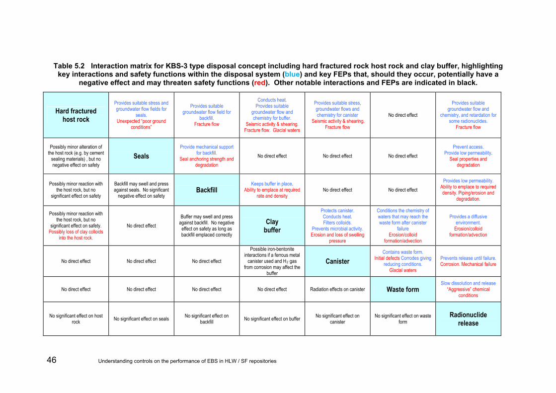
Table 5.2 Interaction matrix for KBS-3 type disposal concept including hard fractured rock host rock and clay buffer, highlighting key interactions and safety functions within the disposal system (blue) and key FEPs that, should they occur, potentially have a
negative effect and may threaten safety functions (red). Other notable interactions and FEPs are indicated in black.
Hard fractured host rock
Provides suitable stress and groundwater flow fields for
seals. Unexpected “poor ground
conditions”
Provides suitable groundwater flow field for
backfill. Fracture flow
Conducts heat. Provides suitable
groundwater flow and chemistry for buffer.
Seismic activity & shearing. Fracture flow. Glacial waters
Provides suitable stress, groundwater flows and chemistry for canister
Seismic activity & shearing. Fracture flow
No direct effect
Provides suitable groundwater flow and
chemistry, and retardation for some radionuclides.
Fracture flow
Possibly minor alteration of the host rock (e.g. by cement
sealing materials) , but no negative effect on safety
Seals Provide mechanical support
for backfill. Seal anchoring strength and
degradation No direct effect No direct effect No direct effect
Prevent access. Provide low permeability.
Seal properties and degradation
Possibly minor reaction with the host rock, but no
significant effect on safety
Backfill may swell and press against seals. No significant
negative effect on safety Backfill
Keeps buffer in place. Ability to emplace at required
rate and density No direct effect No direct effect
Provides low permeability. Ability to emplace to required density. Piping/erosion and
degradation.
Possibly minor reaction with the host rock, but no
significant effect on safety. Possibly loss of clay colloids
into the host rock.
No direct effect Buffer may swell and press
against backfill. No negative effect on safety as long as backfill emplaced correctly
Clay buffer
Protects canister. Conducts heat. Filters colloids.
Prevents microbial activity. Erosion and loss of swelling
pressure
Conditions the chemistry of waters that may reach the waste form after canister
failure Erosion/colloid
formation/advection
Provides a diffusive environment.
Erosion/colloid formation/advection
No direct effect No direct effect No direct effect
Possible iron-bentonite interactions if a ferrous metal
canister used and H2 gas from corrosion may affect the
buffer
Canister Contains waste form.
Initial defects Corrodes giving reducing conditions.
Glacial waters
Prevents release until failure. Corrosion. Mechanical failure
No direct effect No direct effect No direct effect No direct effect Radiation effects on canister Waste form Slow dissolution and release
“Aggressive” chemical conditions
No significant effect on host rock No significant effect on seals No significant effect on
backfill No significant effect on buffer No significant effect on canister
No significant effect on waste form
Radionuclide release
46 Understanding controls on the performance of EBS in HLW / SF repositories

Table 5.3 Interaction matrix for disposal concepts including mudrock host rock and clay buffer, highlighting key interactions and safety functions within the disposal system (blue) and FEPs that, should they occur, potentially have a negative effect and may
threaten safety functions (red). Other notable interactions and FEPs are indicated in black.
Mudrock host rock
Provides suitable stress & groundwater flow fields for
seals. Unexpected “‘poor ground
conditions”.
Provides suitable groundwater flow field for
backfill.
Conducts heat. Provides suitable
groundwater flows and chemistry for buffer.
Glacial waters.
Provides suitable stress, groundwater flows and chemistry for canister
Seismic activity & shearing. No direct effect
Provides suitable groundwater flow and
chemistry, and retardation for some radionuclides.
Possibly minor alteration of the host rock (e.g. by cement
sealing materials) , but no negative effect on safety
Seals Provide mechanical support
for backfill. Seal anchoring strength &
degradation. No direct effect No direct effect No direct effect
Prevent access. Provide low permeability.
Seal properties and degradation.
Possibly minor reaction with the host rock, but no
significant effect on safety
Backfill may swell and press against seals. No significant
negative effect on safety Backfill
Keeps buffer in place. Ability to emplace at required
rate and density. No direct effect No direct effect
Provides low permeability & retardation for some
radionuclides. Ability to emplace to required
density. Degradation.
No significant effect on safety No direct effect Buffer may swell and press
against backfill. No negative effect on safety as long as backfill emplaced correctly
Clay buffer
Protects canister. Conducts heat. Filters colloids.
Prevents microbial activity. Loss of swelling pressure.
Conditions the chemistry of waters that may reach the waste form after canister
failure
Provides a diffusive environment & retardation for
some radionuclides.
No direct effect No direct effect No direct effect
If a ferrous metal canister is used there may be iron-
bentonite interactions and H2 gas from corrosion may affect
the buffer
Canister Contains waste form.
Initial defects. Corrodes giving reducing conditions.
Glacial waters.
Prevents release until failure. Corrosion. Mechanical failure.
No direct effect No direct effect No direct effect No direct effect Radiation effects on canister Waste form Slow dissolution and release
‘Aggressive’ chemical conditions.
No significant effect on host rock No significant effect on seals No significant effect on
backfill No significant effect on buffer No significant effect on canister
No significant effect on waste form
Radionuclide release
Understanding controls on the performance of EBS in HLW / SF repositories 47

Table 5.4 Interaction matrix for disposal concepts including mudrock host rock and supercontainer with cement buffer, highlighting key interactions and safety functions within the disposal system (blue) and FEPs that, should they occur, potentially have a negative
effect and may threaten safety functions (red). Other notable interactions and FEPs are indicated in black.
Mudrock host rock
Provides suitable stress & groundwater flow fields for
seals. Unexpected “poor ground
conditions”.
Conducts heat. Migration of aggressive
species from the host rock may corrode the envelope.
No direct effect No direct effect No direct effect Provides a low permeability, preferably diffusive, barrier to radionuclide migration. Sorbs
some radionuclides.
Early seal emplacement allows rapid re-saturation and prevents excessive host rock
deformation or oxidation Seals No direct effect No direct effect No direct effect No direct effect
Prevent access. Provide low hydraulic
conductivity. Seal properties and
degradation.
May limit the chemical alteration of the host rock by
the cement buffer No direct effect Supercontainer
envelope
Conducts heat. Facilitates fabrication of buffer, and
handling and emplacement of supercontainer
No direct effect No direct effect No direct effect or defined safety function
Localised chemical alteration of the host rock immediately outside the supercontainer
No direct effect Conditions high-pH,
passivates the envelope and minimises corrosion
Cement buffer
Conducts heat. Conditions high-pH. Prevents
rapid localised corrosion & microbial activity.
Limits chemical species migration
High pH may enhance HLW glass dissolution after
overpack failure.
Limits migration of some radionuclides and limits
solubility of some radionuclides by causing high
pH conditions
No direct effect No direct effect No direct effect
Heat may affect the moisture content and solid phases of the cement buffer. H2 gas from corrosion may move
through the buffer
Steel overpack
Provides complete containment for the thermal
phase. Corrodes predictably & gives
reducing conditions.
Provides complete containment for the thermal
phase. Corrodes predictably & gives
reducing conditions.
No direct effect No direct effect No direct effect No direct effect Radiation effects on overpack Waste form Slow dissolution and release after overpack failure
No significant effect on host rock No significant effect on seals No significant effect on
envelope No significant effect on buffer No significant effect on overpack
No significant effect on waste form
Radionuclide release
48 Understanding controls on the performance of EBS in HLW / SF repositories

Understanding controls on the performance of EBS in HLW / SF repositories 49
Table 5.5 Interaction matrix for disposal concepts including evaporite host rock and salt backfill, highlighting key interactions and safety functions within the disposal system (blue) and FEPs that, should they occur, potentially have a negative effect and may
threaten safety functions (red). Other notable interactions and FEPs are indicated in black.
Evaporite host rock
Provides suitable stress field for seals.
Unexpected “poor ground conditions”.
Creeps and compresses backfill
Conducts heat. Essentially prevents water from reaching
the canister. Brine pockets, interbeds.
No direct effect Essentially prevents water from being able to leach
radionuclides. Brine pockets, interbeds.
Possibly minor alteration of the host rock (e.g. by cement
sealing materials) , but no negative effect on safety
Seals
Provide mechanical support for backfill and prevent water
flow. Seal anchoring strength and
degradation.
Essentially prevents water from reaching the canister.
Seal degradation. No direct effect
Prevent access. Provide low hydraulic
conductivity. Seal properties and
degradation.
No significant negative effect on safety
No significant negative effect on safety
Salt backfill
Conducts heat. Fills tunnels and prevents water from reaching the
canister. Ability to emplace at required
density.
No direct effect Provides low hydraulic
conductivity. Poor backfilling.
No direct effect No direct effect Heat will largely drive the thermo-hydro-mechanical behaviour of the backfill.
Minor gas generation possible Canister
Contains waste form. Initial defects.
Minor corrosion leading to reducing conditions.
Water inflow.
Prevents release until failure. Corrosion. Mechanical failure.
No direct effect No direct effect No direct effect Radiation effects on canister Waste form Slow dissolution and release
Stability of HLW glass in brine.
No significant effect on host rock No significant effect on seals No significant effect on
backfill No significant effect on
canister No significant effect on waste
form Radionuclide
release

5.3 FEP audit FEPs and FEP groups identified in Section 5.2 were audited against FEPs in the NEA’s FEP list (NEA, 2000; Appendix B). The aims of the audit were to:
• build confidence that the FEPs and FEP groups identified in Section 5.2 cover all the potentially important controls on repository performance;
• define more precisely the FEPs and FEP groups identified in Section 5.2 in terms of the “standard” FEP definitions in the NEA’s FEP list;
• provide a means for linking the scoping calculations in Section 6 to individual FEPs in the standardised NEA’s FEP list.
Definitions of FEPs in the NEA list are general. Furthermore, each FEP could influence every other FEP to some degree (only a subset of these will influence repository performance directly). These factors mean that there is some subjectivity in judgments of:
• FEPs that should be screened from the NEA’s FEP list;
• FEPs that should be represented implicitly10 or explicitly in audit;
• correspondence between the FEPs in Section 5.2 and FEPs in the NEA list.
Firstly, the audit involved removing FEPs from the NEA list that were irrelevant for this project or redundant because their effects could be represented by other FEPs (see Appendix B for details of the screening process; screened NEA FEPs are in Table B.2). The second step was to identify FEPs from this list that corresponded completely or in part to each FEP or group identified in Section 5.2. This exercise did not determine which FEPs in the screened list could impact on each FEP or group from Section 5.2. For example, in the case of the KBS-3 type disposal concept including a hard fractured host rock and a clay buffer (Table 5.2), the FEP group “‘Aggressive chemical conditions caused by waste form” is a potential cause of radionuclide release. This FEP group is effectively described by four FEPs in the screened NEA’s FEP list:
• 2.1.09 Chemical/geochemical processes & conditions (in wastes and EBS).
• 3.2.01 Dissolution, precipitation and crystallisation, contaminant.
• 3.2.02 Speciation and solubility, contaminant.
• 3.2.03 Sorption/desorption processes, contaminant.
This comparison revealed that each of the FEPs and FEP groups identified in Section 5.2 correspond to at least one FEP in the screened NEA’s list. Conversely, each of the FEPs in this list is represented by at least one FEP or group in Section 5.2 in at least one of the concepts considered. That is, the audit builds confidence that all likely key controls on repository performance have been taken into account.
10 A FEP is represented implicitly if it is excluded from the subset of NEA FEPs to be compared with the FEPs and FEP groups identified in Section 5.2, but would have the same net effect as one or more FEPs included in this subset of NEA’s FEPs.
50 Understanding controls on the performance of EBS in HLW / SF repositories

In a few cases, a particular FEP from Table B.2 was not represented by the collection of safety functions and threats to safety functions corresponding to one or more of the considered concepts. These cases are summarized in Table 5.6 below.
Understanding controls on the performance of EBS in HLW / SF repositories 51

Understanding controls on the performance of EBS in HLW / SF repositories 52
Table 5.6 Summary of NEA FEPs from screened list in Table B.2 that are not relevant to any disposal concepts. Yellow shading indicates that the FEP corresponds to one or more safety functions and/or threats to safety functions appropriate to the concept listed
in the left-most column of the table.
FEPs from NEA FEP List 1.1.09 1.2.03 1.2.09 2.1.06 2.1.12 2.2.01 2.2.05
Concepts Schedule and planning
Seismicity Salt diapirism and dissolution
Other engineered materials features and characteristics
Gas sources and effects (in wastes and EBS)
Excavation disturbed zone/host rock
Contaminant transport path characteristics (in geosphere)
Longer-lived waste package/overpack + clay buffer + hard fractured rock
Not considered Considered Not considered Not considered Not considered Considered Considered
Mudrock host rock and a clay buffer Not considered Considered Not considered Not considered Considered Considered Considered
Mudrock host rock and a supercontainer with a cement buffer
Considered Not considered Not considered Considered Considered Considered Considered
Evaporite host rock and a salt backfill Not considered Not considered Considered Not considered Considered Not considered Not considered
Explanation of differences between FEPs considered
For mudrock host rock with supercontainer and cement buffer, early sealing is favourable for long-term supercontainer functioning. In other concepts, scheduling will be important but is not mentioned explicitly.
Environments where a supercontainer has been proposed have plastic clay host rock and brittle deformation is unlikely, hence seismicity is not considered a threat. In concepts where host rocks could undergo brittle deformation seismicity may be more significant.
Salt diapirism and dissolution is likely to be important only for the concept with an evaporite host rock.
Only in the case of the supercontainer are components that are not represented explicitly by other FEPs considered to be significant from the perspective or repository performance.
The KBS-3-based concept has a relatively longer-lived Cu-canister and H2 gas from corrosion will be insignificant. However, in all the other concepts, Fe/steel canisters will be used and corrosion could generate greater amounts of H2.
The EDZ developed in an evaporite host rock would probably self-seal rapidly compared with the time taken for waste containers to fail. Therefore this FEP is not considered for the evaporite host rock concept, but excavation disturbance could be more important in other host rocks.
Continuous contaminant transport paths are unlikely to occur in a salt host rock. In contrast, such pathways are much more likely in other rock types.

6 Assessment and implications Calculations were undertaken as an aid to identifying factors that would influence the performance of the different EBS components, for each of the four combinations of disposal concept and host rocks in Table 5.2 to Table 5.5. Simple descriptions (conceptual models) of each of the four host rocks and associated disposal concepts were developed as a basis for the calculations. These are illustrated in Figure 6.1 to Figure 6.4.
In the subsequent text the different concepts are referred to as follows:
• Concept 1: strong fractured host rock with KBS-3V type concept.
• Concept 2: mudrock with clay buffer.
• Concept 3: mudrock with supercontainer and cement buffer.
• Concept 4: salt with salt backfill.
For each concept, a number of variants are explored to help identify key controls; although the variants are designed for situations that may occur, their inclusion does not imply that they are likely to occur for any particular repository.
All the calculations presented here are for a single canister. There is no reason to believe that there is any strong influence from one canister on another except through thermal effects that are not explicit in the calculations. Different threats will be relevant for the whole repository or for just a few canisters; the calculations here should be viewed as being for a typical canister.
6.1 Conceptual models Figure 6.1 shows the KBS-3V type disposal concept (Concept 1) in hard fractured host rock. Although the host rock is of low permeability at large scales, at small scales advective groundwater flow and contaminant transport will occur in the fractures if there is a head gradient to drive flow, as shown in Figure 6.1. Large fractures may intersect the access tunnels, but disposal holes that intersect large fractures will not be used. Smaller fractures are assumed to provide only local connections and are considered to form part of the ‘background’ geosphere pathway rather than the direct potentially high flow pathway through large fractures. The rock matrix between fractures has very low permeability in these systems and there is no major flow other than in the fractures.
The buffer, backfill and seals comprise clays (swelling bentonite for the buffer and seal, and natural swelling clay for the backfill) with hydraulic conductivities specified by the design that are much lower than the geosphere’s hydraulic conductivity. Since these materials are plastic, and swell, under design conditions they will not contain any fractures. Contaminant transport will be by diffusion. The key purpose of the buffer is to provide physicochemical protection of a long-lived (copper in the KBS-3V concept) canister that is the main barrier. In this concept we assume the seals play a relatively minor role in mitigating radionuclide transport. Rather, they act as operational components, and their role in long-term performance is limited to maintaining the general integrity of the repository by limiting fluid migration and resisting the swelling pressure developed in the buffer/backfill.
Understanding controls on the performance of EBS in HLW / SF repositories 53

Buffer
Backfill Seal
EDZ
Waste
Canister
Small Fracture
Large Fracture
Potential release
pathways
Buffer
Backfill Seal
EDZ
Waste
Canister
Small Fracture
Large Fracture
Potential release
pathways
Figure 6.1 Conceptual model for hard fractured host rock with KBS-3V type disposal (Concept 1), with potential radionuclide release pathways indicated by
red arrows.
Figure 6.2 shows the model for waste disposed in a clay buffer in mudrock (Concept 2). In this case any fractures in the mudrock are considered to be non-conductive of water, solutes and gas at repository scales and hence are not represented. The host rock (geosphere) is of low hydraulic conductivity such that groundwater flows are negligible and contaminant transport will be dominated by diffusion. The hydraulic conductivity will be enhanced in the EDZ, although it will still be low. Flow in the EDZ will be enhanced compared with the host rock and some flow will focus towards the EDZ.
The low hydraulic conductivity of the host rock means that groundwater heads at repository depth might not be in equilibrium with ground surface boundary conditions. The resultant vertical head gradients may be high (far higher than can be sustained in a relatively conductive fractured host rock) and might drive flow in the EDZ. However, this potential vertical head gradient is more relevant to flow in the EDZ of the inclined/vertical access tunnels rather than local flow in the EDZ around emplacement tunnels, because these large-scale features can connect (possibly via their associated EDZ) zones of high and low groundwater head. This could induce groundwater flows and create transport pathways to potential receptors.
The waste is disposed in a shorter-lived canister that provides operational shielding and acts as a barrier. This canister is primarily intended to act as a barrier during the early heat-generating phase in which material performance is more uncertain, solubilities and radionuclide mobility generally higher and, in the case of HLW, glass dissolution rates elevated (Andra, 2005c). However, since the supply of oxidants to the
54 Understanding controls on the performance of EBS in HLW / SF repositories

canister will be low due to the low hydraulic conductivity host rock and buffer, the canister may act as a barrier for a long time. Again we assume that the seals play a relatively minor role mitigating radionuclide transport directly, but provide a more general role in maintaining the integrity of the repository by limiting fluid migration.
For this conceptual model, the geosphere is a major barrier, while strong fractured rock is a much less significant barrier. Therefore, total system performance is less reliant on the near-field barriers compared with Concept 1.
Potential release
pathways Seal
Waste
Canister
Clay Buffer
Backfill
EDZ
Perpendicular tunnel and seal
Flow through seal into perpendicular tunnel
backfill
Figure 6.2 Conceptual model for mudrock host rock with clay buffer disposal (Concept 2), with potential radionuclide release pathways indicated by red
arrows.
Figure 6.3 shows the model for waste disposed in a supercontainer with cement buffer in mudrock (Concept 3). The conceptual model is similar to the system with a clay buffer but with a few notable differences. The cement will initially be of high pH and this will increase the lifetime of the canister by reducing the corrosion rate. The cement will degrade with time as it reacts with groundwater and as it degrades its pH will decrease. The porosity and hydraulic conductivity of the concrete may increase as the cement degrades due to leaching of cement minerals and potentially cracking through precipitation of minerals such as ettringite. However, some reactions such as carbonation may decrease the porosity and hydraulic conductivity, and the lithological confining pressure will resist cracking. The reactions that occur will depend on the geochemistry of the host rock porewaters. For the purposes of the calculations presented below, the mean porosity and hydraulic conductivity of the cement are assumed to increase with time.
The supercontainer is made of stainless steel. Although Ondraf/Niras (2002) do not treat this component as a barrier, the stainless steel may act as such for a period of time due to the low rate of supply oxidants in mudrock host rock, and hence low corrosion rates.
Figure 6.4 shows the model for disposal in salt (Concept 4). The canister is disposed in a tunnel that is backfilled with salt. The access tunnels are also backfilled with salt. The salt host rock creeps with time, such that the backfill will reconstitute and its properties will become indistinguishable from the host rock.
Understanding controls on the performance of EBS in HLW / SF repositories 55

The host rock is of very low porosity and hydraulic conductivity. Contaminant transport will be by diffusion alone. Although the canister will corrode, the rate of supply of oxidants in groundwater will be so low that the canister may last for a long time.
Potential release
pathways Seal
Waste
Canister
Cement Buffer
Backfill
EDZ
Perpendicular tunnel and seal
Steel supercontainer
Flow through seal into perpendicular tunnel
backfill
Figure 6.3 Conceptual model for mudrock host rock with supercontainer and cement buffer disposal (Concept 3), with potential radionuclide release pathways
indicated by red arrows.
Potential release
pathways
Waste
Canister
Backfill
Host rock
Perpendicular tunnel and
backfill
Potential release
pathways
Waste
Canister
Backfill
Host rock
Perpendicular tunnel and
backfill
Figure 6.4 Conceptual model for evaporite host rock with salt backfill (Concept 4), with potential radionuclide release pathway indicated by a red arrow.
56 Understanding controls on the performance of EBS in HLW / SF repositories

6.2 Calculations Calculations of barrier performance were undertaken for each of the four concepts using the conceptual models developed above. For each concept, a base case calculation was undertaken along with a number of variant calculations to illustrate the impacts of the FEP groups/safety functions identified in Section 5.2 that threaten barrier performance.
Additionally, for Concept 1, probabilistic calculations were undertaken to explore the sensitivity to event timing (canister failure) and to parameter values (dissolution rate, solubility limit and distribution coefficient). The effects of these parameter variations for the other concepts would be expected to be similar.
6.2.1 Concept 1
From Table 5.2 and the experience of SKB (2006a), that the canister is the primary containment mechanism, and, when operating as designed, releases from the canister will be negligible. Furthermore, SKB (2006a) states that during the normal evolution of the KBS-3V concept, canister failure is not anticipated within the 1 million year timescale of the safety assessment. Although some diffusion of H-3 through the metal canister may occur, due to the short half-life of H-3 the release from the near-field will be negligible. The diffusion time for other radionuclides is sufficiently long to limit the possibility of any major release. Therefore for Concept 1 base case there will not be any releases from the near-field, and so no calculations were made.
The only mechanism for release of radionuclides without human intrusion is if some or all of the canisters fail. On the basis of the information given in Table 5.2 and SKB (2006a), hypothetical canister failure scenarios are considered for Concept 1 to form variant calculations that cover a range of failure scenarios. It is stressed that these scenarios are not expected to occur and the calculations were undertaken simply to illustrate the consequences of the hypothetical failure mechanisms. Failure of the canisters is considered to come about from defects in the canister as constructed, failure of the buffer to protect the canister from corrosion and natural disruption of the canister/buffer system. This gives rise to the following three variant cases to investigate the likely effects of different types of canister failure:
• growing pinhole;
• buffer erosion and canister corrosion;
• canister shearing.
The first variant to be considered is the growing pinhole case. It is assumed that some copper canisters have a pinhole defect in the welds. Consistent with SKB (2006a) the pinhole is taken to be two mm in diameter. Radionuclide releases from the canister, due to corrosion of the iron canister insert causing gas generation and pressurisation within the canister, and due to heat generation in the canister, do not occur for the first thousand years. Radionuclides then begin to diffuse out of the canister through the pinhole at 1,000 years until conservatively the canister is assumed to fail completely at 10,000 years, owing to the loss of strength caused by the corrosion of the iron insert. At this time diffusive release of contaminants occurs across the whole canister surface.
In the second variant, relatively oxidizing groundwater is introduced to repository depth by a process such as glacial loading. Erosion of the buffer by this groundwater flowing in host rock fractures is assumed to cause exposure of the canister to increased fluxes of oxidizing groundwater. The locally increased flux of dissolved oxidants increases the
Understanding controls on the performance of EBS in HLW / SF repositories 57

canister corrosion rate, which is virtually zero under undisturbed reducing conditions. Once a canister fails, the eroded buffer does not act as a barrier. Corrosion is assumed to be uniform, and results in canister failure at 100,000 years.
The mechanism of corrosion for the uniform corrosion case is different to the pinhole case. The pinhole corrosion assumes a manufacturing defect in the canister which is exploited by geochemical conditions inside the canister. This permits relatively rapid corrosion along a tightly focussed section of copper. In contrast, the uniform corrosion case considers the impact of microbial and geochemical conditions outside the canister and is considered by SKB to be a much slower process occurring over the whole surface of the canister.
The third variant assumes that a tectonic event occurs at 100,000 years, resulting in movement along a fracture in the host rock. This movement shears the canister and increases the hydraulic conductivity of the fracture. The canister is assumed to fail completely due to shearing. A fracture cannot develop through the buffer, which exhibits plastic behaviour, but transport through the buffer increases due to the increased geosphere fracturing.
No variant for seal failure is considered here, as the effect of the seals in this concept is not important for containment of radionuclides; in fractured rocks there will be paths that bypass the seal and its role is to physically contain the backfill. However, the seals are vital to maintaining the integrity of the EBS and hence the canister.
6.2.2 Concept 2
As reflected in Table 5.3, a key aspect of Concept 2 is that it cannot be assumed that the iron canister will remain intact as a barrier to radionuclide release for as long as in Concept 1 For the Concept 2 base case, the iron canister is assumed to begin to fail after 10,000 years and to have completely failed after 100,000 years, consistent with Andra (2005c). Therefore, there are no releases in the first 10,000 years.
Table 5.3 also highlights mechanisms by which performance of the disposal system may be compromised, through release of more radionuclides from the waste form or disposal package, or mechanisms that may lead to enhanced transport to potential receptors. Therefore in addition to the base case, three variant calculations were undertaken for Concept 2.
• repository seal failure;
• shearing of the canister;
• poor buffer construction.
Seal failure and poor buffer construction variants are exactly as the base case, except that the seal and buffer are assumed to contain construction defects which could enhance transport and release to potential receptors. This is reflected in elevated hydraulic conductivities of these features. Although flows through the near-field will be increased if these barriers are defective, the flows will still be small due to the low hydraulic conductivity of the host rock.
For the shear failure variant to have a major impact on releases, the shearing event is assumed to occur at 10,000 years compared with 100,000 years in Concept 1. If the shearing event were assumed to occur at 100,000 years, the canister would have already failed for Concept 2. This case is an ‘extreme’ canister failure scenario and is unlikely to occur through natural processes (such as seismic- or glaciation-induced stresses, for example) in England and Wales.
58 Understanding controls on the performance of EBS in HLW / SF repositories

It is assumed that the host rock is not plastic and a transmissive fracture develops in it. Consistent with Concept 1, the clay buffer, backfill and seal are assumed to be plastic, so the fracture does not pass through these features. Although a fracture can develop in the host rock, it is assumed that, unlike Concept 1, transport through the buffer does not increase notably. Unless the fracture zone is connected to a more permeable horizon (source of water), flow in the fracture that connects to the buffer will be low.
Buffer erosion is not relevant in a mudrock host rock.
6.2.3 Concept 3
Concept 3 is similar to Concept 2 (compare Table 5.3 to Table 5.4), except that the waste is assumed to be within a stainless steel supercontainer that contains a cement backfill. Because of this similarity only the base case calculations are considered for this concept for comparison with the Concept 2 base case.
As identified in Table 5.4 the supercontainer itself has no post-closure safety function; its sole purpose is to aid manufacturing and emplacement of the waste package. However, its presence will have an impact on canister degradation times. Ondraf/Niras (2002) stated that such a container should remain sealed for a minimum of 2,000 years if a clay buffer is used. With a cement buffer the supercontainer could last longer due to the higher pH of the cement and hence reduced corrosion of the inside of the container. Depending on the host rock conductivity and supply of oxidants, the container could potentially form a barrier for much longer. However, for the purposes of these calculations it is assumed that the supercontainer begins to fail after 2,000 years and completely fails after 5,000 years.
Ondraf/Niras (2002) state that the canister is designed to remain sealed for a minimum of 1,000 years assuming a clay buffer. With a cement buffer, and taking into account the time for the supercontainer to degrade, it is assumed that the canister begins to fail after 10,000 years. It is also assumed that the canister has completely failed after 150,000 years. This is slightly later than for Concept 2, to illustrate the potential impact of reduced corrosion rates due to the cement. As the cement degrades and the pH in the buffer decreases, the canister corrosion rate will increase. The cement is therefore treated as having degraded fully at the time of total canister failure.
The porosity and hydraulic conductivity of the cement, and the distribution coefficients and diffusivities of the radionuclides within the cement change linearly with time as the cement degrades. Radionuclide solubilities in the cement porewaters entering the waste canister change in a stepwise manner as the solubility limiting phases change. Solubility limits in the waste canister are assumed to exhibit a step change once the concrete has fully degraded.
An alkaline plume is released from the supercontainer and degrades the adjacent host rock, backfill and clay seals; the calculations assume that this degradation increases their hydraulic conductivities. Although this process increases the flow through the near-field, the effect will be limited by the low conductivity of the host rock outside of the alkaline altered zone.
6.2.4 Concept 4
Table 5.5 shows that the primary safety functions for this concept relate to the small quantities of free water available to corrode the disposal canisters to mediate the transport of radionuclides from the water to potential receptors. Hence for Concept 4, a
Understanding controls on the performance of EBS in HLW / SF repositories 59
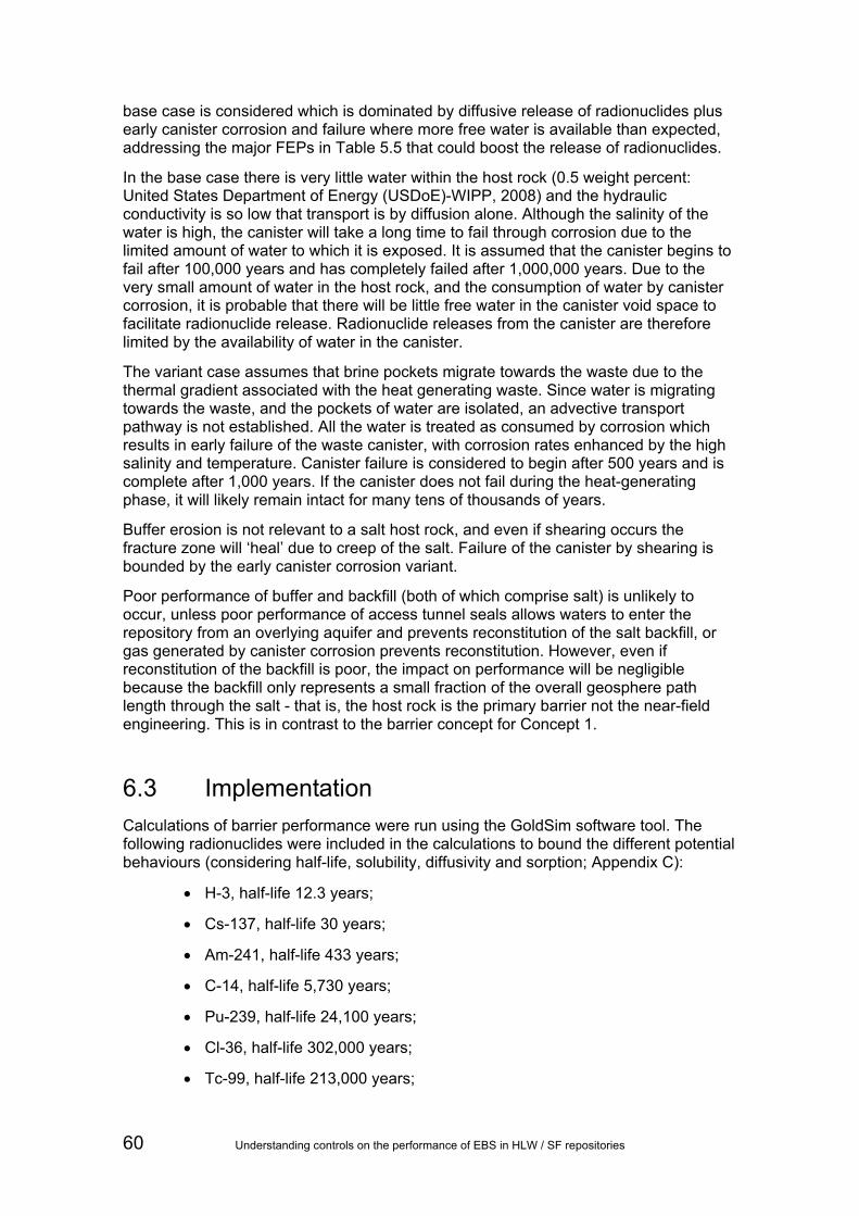
base case is considered which is dominated by diffusive release of radionuclides plus early canister corrosion and failure where more free water is available than expected, addressing the major FEPs in Table 5.5 that could boost the release of radionuclides.
In the base case there is very little water within the host rock (0.5 weight percent: United States Department of Energy (USDoE)-WIPP, 2008) and the hydraulic conductivity is so low that transport is by diffusion alone. Although the salinity of the water is high, the canister will take a long time to fail through corrosion due to the limited amount of water to which it is exposed. It is assumed that the canister begins to fail after 100,000 years and has completely failed after 1,000,000 years. Due to the very small amount of water in the host rock, and the consumption of water by canister corrosion, it is probable that there will be little free water in the canister void space to facilitate radionuclide release. Radionuclide releases from the canister are therefore limited by the availability of water in the canister.
The variant case assumes that brine pockets migrate towards the waste due to the thermal gradient associated with the heat generating waste. Since water is migrating towards the waste, and the pockets of water are isolated, an advective transport pathway is not established. All the water is treated as consumed by corrosion which results in early failure of the waste canister, with corrosion rates enhanced by the high salinity and temperature. Canister failure is considered to begin after 500 years and is complete after 1,000 years. If the canister does not fail during the heat-generating phase, it will likely remain intact for many tens of thousands of years.
Buffer erosion is not relevant to a salt host rock, and even if shearing occurs the fracture zone will ‘heal’ due to creep of the salt. Failure of the canister by shearing is bounded by the early canister corrosion variant.
Poor performance of buffer and backfill (both of which comprise salt) is unlikely to occur, unless poor performance of access tunnel seals allows waters to enter the repository from an overlying aquifer and prevents reconstitution of the salt backfill, or gas generated by canister corrosion prevents reconstitution. However, even if reconstitution of the backfill is poor, the impact on performance will be negligible because the backfill only represents a small fraction of the overall geosphere path length through the salt - that is, the host rock is the primary barrier not the near-field engineering. This is in contrast to the barrier concept for Concept 1.
6.3 Implementation Calculations of barrier performance were run using the GoldSim software tool. The following radionuclides were included in the calculations to bound the different potential behaviours (considering half-life, solubility, diffusivity and sorption; Appendix C):
• H-3, half-life 12.3 years;
• Cs-137, half-life 30 years;
• Am-241, half-life 433 years;
• C-14, half-life 5,730 years;
• Pu-239, half-life 24,100 years;
• Cl-36, half-life 302,000 years;
• Tc-99, half-life 213,000 years;
60 Understanding controls on the performance of EBS in HLW / SF repositories

• Zr-93, half-life 1,530,000 years;
• Np-237, half-life 2,140,000 years;
• I-129, half-life 15,700,000 years;
• U-235, half-life 704,000,000 years.
These radionuclides were selected to represent the full range of half-lives and major chemical properties, notably tendency to sorb and redox sensitivity, exhibited by the radionuclides present in large amounts in the UK radioactive waste inventory (Defra and NDA, 2008). The approach to selecting these radionuclides is described in Appendix C. In a full assessment, it would be necessary to model more radionuclides, but for the purposes of this study, which aims to understand the way in which the different barriers limit releases, a representative set suffices.
Radionuclide decay was considered in the calculations, but the in-growth and subsequent behaviour of daughter radionuclides was not considered. In the chains of interest there is a long-lived nuclide (U-238, U-235, Np-237, Th-232) that can decay into a chain of shorter-lived daughters. During transport through the geosphere, the original inventory of these daughters will decay, but there will be ongoing generation (in-growth) due to decay of the long-lived nuclide. Thus, the rate at which the daughters arrive in the near-surface environment is decoupled from the rate at which they leave the EBS. Rather, their arrival rates at the surface will depend on the rates at which the long-lived nuclides leave the EBS, therefore the parent radionuclides are the focus here. Also worth comment is the case where relatively short-lived parents decay to relatively long-lived daughters (such as Am-241 to Np-237). In this case the daughter activities generated are negligible and so these decays and in-growth can be safely omitted from the calculations.
Groundwater flow and radionuclide transport calculations were run by representing the disposal systems using a number of cells in GoldSim. A generic discretisation was developed that enables calculations for the different conceptual models and variants by selecting appropriate input data using a switch in the GoldSim model.
The discretisation is illustrated in Figure 6.5 and comprises:
• one cell representing the waste;
• one cell representing the void space between the waste and the canister;
• five cells representing the buffer;
• five cells representing the backfill;
• five cells representing the geosphere (note that the first geosphere cell is actually split into two cells).
Five cells are used for each of the buffer, backfill and geosphere. Although this is a coarse discretisation, it is adequate for these calculations. In diffusive zones, a pseudo-equilibrium profile is quickly established and a small number of cells is able to capture this well; in advective cases, a small number of cells introduces numerical dispersion with an effective Peclet number of twice the number of cells, 10 in the current case, which broadly corresponds to Peclet numbers observed in macroscopic systems over a wide range of lengths. The numerical approximations introduced have little effect on calculated breakthroughs, particularly compared to the inevitable uncertainty in transport properties. A numerical study of these issues was done by Xu et al. (2007).
Understanding controls on the performance of EBS in HLW / SF repositories 61

The canister, seal and supercontainer are not represented as cells, but their impacts on release and groundwater flows through the components are accounted for in the calculations through the way they control flow and transport between cells in the neighbouring components.
Z
X
Y
FP1 FP2
FP3
Fuel
Void
Canister
Buffer
Backfill
Seal
Supercontainer
Geosphere
Affect flows, but not represented as cells.
Z
X
Y
FP1 FP2
FP3
Fuel
Void
Canister
Buffer
Backfill
Seal
Supercontainer
Geosphere
Affect flows, but not represented as cells.
Figure 6.5 Generic discretisation used in the GoldSim calculations here. The red lines show the flow paths modelled.
The calculations consider a single waste canister. The inventory is taken from SKB (2006b), and the same inventory is used for all conceptual models and variant calculations to make them comparable. However, it is not our intention to state that one disposal system performs better than another, but rather to provide a common basis to illustrate different aspects of performance. This is an important point because these calculations only consider near-field barrier performance. The different concepts are designed taking into account the overall near-field and geosphere system performance as a whole. As the performance of the geosphere as a barrier increases, so the required performance of the near-field barriers decreases. For example, the canister performance in Concept 1 would need to be greater than the canister performance in Concept 2. These differences reflect the fact that in Concept 1 transport in the host rock is advection-dominated, whereas in Concept 2 it is diffusion-dominated.
The inventory considers radionuclides within the matrix of the fuel and an IRF on the surface of the fuel and along fuel grain boundaries. The matrix inventory is assigned to the cell representing the waste and the IRF is assigned to the cell used to represent the void space between the fuel and the canister. Once the canister fails and water enters, radionuclides can be released from the void space. The fuel begins to dissolve (at a slow rate) on contact with water, releasing additional radionuclides to the void space.
For HLW the main differences would be: a different inventory; an absence of the IRF; and a different, generally faster, dissolution rate from the waste form (Nagra 2002).
62 Understanding controls on the performance of EBS in HLW / SF repositories

Three flow paths (FP) are considered (Figure 6.5):
• through the buffer to the geosphere (FP1);
• through the buffer and backfill to the geosphere (FP2);
• through the buffer, backfill and seal to the geosphere (FP3).
Note that these paths have diffusive components as well as advective components. Diffusion is treated as occurring radially.
For Concept 1, equivalent flow rates were used from SKB (2006a). These rates sum the contributions of advection and diffusion and were applied throughout the buffer. It is possible to explore the behaviour of advection and diffusion separately through input parameters; it is simply a modelling convenience to lump the processes into a single flux. Only the advective equivalent flows along FP1, 2 and 3 were considered in the calculations. Radial diffusion was not considered explicitly. Calculating flow proportions along different pathways is complex; however for illustrative purposes it was assumed that 75 per cent of the transport through the buffer is to the geosphere (FP1) and 25 per cent is to the backfill (FP2). Flow through the seal (FP3) was not considered because it was assumed that the primary purpose of the seal is to maintain the integrity of the repository as a whole. The consequence of the seal not performing as designed would be to increase the availability of water and net flow rates, not create a specific transport path.
For Concepts 2 and 3, the hydraulic conductivities of each material with time were specified. These were used to calculate the most conductive flow path (FP1, 2 or 3), with advective flow and transport occurring along the most conductive flow path. Radial diffusion was included explicitly in the calculations.
For Concept 4 there is no advective flow, and only radial diffusion was considered. Advective flows along FP1, 2 and 3 were set to zero.
Key data used in the calculations are summarised in Table 6.1.
Table 6.1 Data used in the calculations.
Parameter Concept 1 Concept 2 Concept 3 Concept 4 Canister inventory
SKB (2006b) SKB (2006b) SKB (2006b) SKB (2006b)
Matrix dissolution rate
SKB (2006b) SKB (2006b) SKB (2006b) SKB (2006b)
Solubility limits SKB (2006b) (Limit for U
only)
SKB (2006b) (Limit for U
only)
Mallants et al. (2005)
Assume as Case 1 in
absence of specific data
Buffer Kd SKB (2006b) SKB (2006b) Savage and Stenhouse
(2002)
US EPA (1998)
Buffer porosity SKB (2006b) SKB (2006b) Savage and Stenhouse
(2002)
WIPP (2008)
Buffer relative diffusivities
Use equivalent flow rates from SKB (2006b)
SKB (2006b) Mallants et al. (2005)
Assume as Case 1 in
absence of specific data
Buffer Use equivalent SKB (2006b) Assumed N/A
Understanding controls on the performance of EBS in HLW / SF repositories 63

Parameter Concept 1 Concept 2 Concept 3 Concept 4 hydraulic
conductivity flow rates from SKB (2006b)
no flow
Backfill Kd SKB (2006b) SKB (2006b) SKB (2006b) US EPA (1998)Backfill porosity
SKB (2006b) SKB (2006b) SKB (2006b) WIPP (2008)
Backfill relative diffusivities
Use equivalent flow rates from SKB (2006b)
SKB (2006b) SKB (2006b) Assume as Case 1 in
absence of specific data
Backfill hydraulic
conductivity
Use equivalent flow rates from SKB (2006b)
Assumed Assumed N/A no flow
Seal hydraulic conductivity
Use equivalent flow rates from SKB (2006b)
SKB (2006b) SKB (2006b) N/A no flow
Host rock Hard fractured rock (K of 1.0 x 10⁻⁹ m/s based on Watson et al. (2007). For
Case 3 (shearing)
average K at the model
scale assumed to increase by
x5)
Mudrock (K of 1.0 x 10⁻¹¹ m/s based on Watson et al. (2007). For
Case 3 (shearing)
average K at the model
scale assumed to increase by
x10)
Mudrock (K of 1.0 x 10⁻¹¹ m/s based on Watson et al.
(2007). K increases to
1.0 x 10⁻⁹ m/s at 100,000
years due to formation of
alkaline disturbed
zone)
Salt (no
groundwater flow)
In all cases, a hydraulic gradient of 0.1 was used in the calculations.
6.4 Results
6.4.1 Results of deterministic calculations
The model results are presented in terms of the ratio of radionuclide flux into and out of each barrier with time, illustrating the significance of each component. The ratios of cumulative fluxes are presented, total out versus total in for each component. Where none of a nuclide reaches the component, it is omitted from the corresponding graph.
Concept 1
Figure 6.6 and Figure 6.7 show the cumulative radionuclide fluxes out of the waste canister compared to the initial waste inventory for the Concept 1 pinhole variant and buffer erosion and canister corrosion variant cases respectively. The canister failure time has a major impact on release of shorter lived radionuclides, and particularly those in the IRF such as C-14, but as half-life increases the impact of canister failure time on cumulative release decreases; for example, for I-129 delaying failure by 90,000 years reduces the cumulative flux at one million years by less than 10 per cent. The results for the canister shear variant are similar to those for the buffer erosion and canister
64 Understanding controls on the performance of EBS in HLW / SF repositories

corrosion variant and so are not shown here. Here the comparison is only between the central deterministic cases. In the following section, probabilistic calculations shed more light on the contributions of variability in input parameters to the results.
Figure 6.8 shows the ratio of the cumulative flux out of the buffer compared with the cumulative flux into the buffer. Note that for some radionuclides at some times, most notably prior to release, fluxes in and out are both zero, the ratio is undefined and hence not plotted over the undefined interval. This figure shows that the buffer acts to delay the release of long-lived mobile radionuclides such as I-129 and Cl-36 but eventually a large proportion of the flux into the buffer will pass out of the buffer. For long-lived radionuclides that are strongly sorbed such as Zr-93, flux out of the buffer is small. The buffer here includes the transport resistance to leave the buffer and enter the next component; it is this resistance that dominates buffer behaviour, rather than diffusion across the buffer itself. The reason this resistance dominates is because the geometry causes radionuclides leaving the waste canister to enter a small fracture through which they can be transported as part of the background advective geosphere transport. This migration invokes a tremendous focussing effect, effectively a four-metre height diffusion front concentrating to a small number of millimetre-scale fractures. This reduces the apparent concentration gradient and hence reduces the diffusive release from the canister. This effect is real and an extremely important aspect of assessing the release of radionuclide from an HLW or SF canister.
For the buffer erosion and canister corrosion variant, the buffer does not act as a barrier and so no results are shown.
Figure 6.9 shows the impact of increased transport through the buffer as a result of shearing and enhanced fracture flow in the host rock. Radionuclide travel times through the buffer are lower than for the pinhole variant.
Figure 6.10 shows the ratio of the cumulative flux out of the backfill compared with the cumulative flux into the backfill for the pinhole variant. Initially there is no flux into the backfill and the ratio is undefined. The flux out of the backfill is initially very small and similar to the very small flux into the backfill. The ratio is unity. As the breakthrough curve from the buffer enters the backfill the ratio falls. As the peak flux from the buffer into the backfill is reached the ratio reaches a minimum. As the flux from the buffer into the backfill begins to decrease, the ratio increases back to unity, except for C-14 which decays significantly in the backfill due to its shorter half-life.
Understanding controls on the performance of EBS in HLW / SF repositories 65
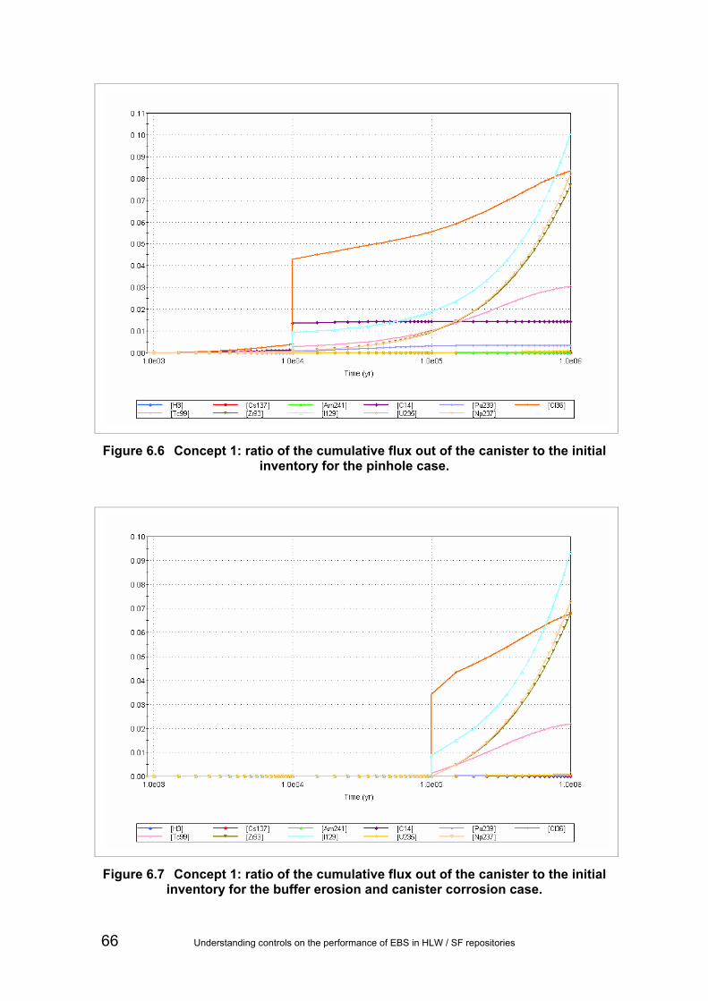
Figure 6.6 Concept 1: ratio of the cumulative flux out of the canister to the initial inventory for the pinhole case.
Figure 6.7 Concept 1: ratio of the cumulative flux out of the canister to the initial inventory for the buffer erosion and canister corrosion case.
66 Understanding controls on the performance of EBS in HLW / SF repositories
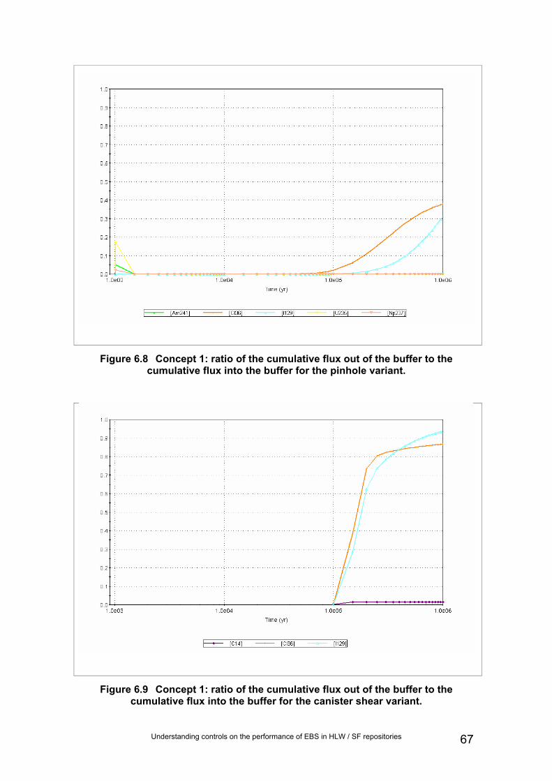
Figure 6.8 Concept 1: ratio of the cumulative flux out of the buffer to the cumulative flux into the buffer for the pinhole variant.
Figure 6.9 Concept 1: ratio of the cumulative flux out of the buffer to the cumulative flux into the buffer for the canister shear variant.
Understanding controls on the performance of EBS in HLW / SF repositories 67

Figure 6.10 Concept 1: ratio of the cumulative flux out of the backfill to the cumulative flux into the backfill for the pinhole variant.
Concept 2
Figure 6.11 shows the cumulative radionuclide fluxes out of the waste canister for the Concept 2 base case. The results are similar to the pinhole variant of Concept 1. The results are also similar to the other Concept 2 variant calculations and for the Concept 3 base case (Figure 6.14), except that for the latter the effects of changing chemistry can be seen for Tc-99 and Np-237 at 100,000 years.
Figure 6.12 shows the ratio of the cumulative flux out of the buffer compared with the cumulative flux into the buffer for the Concept 2 base case. Mobile radionuclides move rapidly through the buffer. The buffer is a less effective barrier than for Concept 1 because in Concept 2 the entire surface area of the buffer is available for radial diffusion into the host rock. For Concept 1, radionuclides are only able to diffuse out of the buffer where host rock fractures intersect the buffer. This illustrates the significance of this ‘mass transport resistance’, which is a real and important effect.
The buffer results for the other Concept 2 variants are similar to the base case.
Figure 6.13 shows the ratio of the cumulative flux out of the backfill compared with the cumulative flux into the backfill for the Concept 2 base case. Similar to the buffer, the backfill is not a major barrier for long-lived mobile radionuclides. The transport of less mobile long-lived radionuclides from the buffer into the backfill is seen, although they are not transported out of the backfill in the 106 year time frame for the calculations. The backfill results are similar for the Concept 2 variant calculations.
68 Understanding controls on the performance of EBS in HLW / SF repositories

Figure 6.11 Concept 2: ratio of the cumulative flux out of the canister to the initial inventory for the base case.
Figure 6.12 Concept 2: ratio of the cumulative flux out of the buffer to the cumulative flux into the buffer for the base case.
Understanding controls on the performance of EBS in HLW / SF repositories 69
Figure 6.13 Concept 2: ratio of the cumulative flux out of the backfill to the cumulative flux into the backfill for the base case.
Concept 3
Figure 6.14 shows the ratio of the cumulative flux out of the canister compared with the initial inventory, while Figure 6.15 shows the ratio of the cumulative flux out of the buffer compared with the cumulative flux into the buffer for the Concept 3 base case. The results are different to the Concept 2 base case, especially after 105 years. The impacts of degradation of the cement buffer can be seen, with radionuclides such as U-235 and Zr-93 able to migrate through the buffer once it has degraded.
Figure 6.16 shows the ratio of the cumulative flux out of the backfill compared with the cumulative flux into the backfill for the Concept 3 base case. The results are similar to the Concept 2 base case, except that some radionuclides are transported more rapidly into the backfill from the buffer.
70 Understanding controls on the performance of EBS in HLW / SF repositories

Figure 6.14 Concept 3: ratio of the cumulative flux out of the canister to the initial inventory for the base case.
Figure 6.15 Concept 3: ratio of the cumulative flux out of the buffer to the cumulative flux into the buffer for the base case.
Understanding controls on the performance of EBS in HLW / SF repositories 71

Figure 6.16 Concept 3: ratio of the cumulative flux out of the backfill to the cumulative flux into the backfill for the base case.
Concept 4
Figure 6.17 and Figure 6.18 show the cumulative radionuclide fluxes out of the waste canister compared to the initial waste inventory for the Concept 4 base case and early canister corrosion variant. In this conceptual model the waste is dry, so the rate of radionuclide diffusion out of the canister is low. The cumulative flux of long-lived radionuclides is not affected by the canister failure time. The flux of shorter lived radionuclides such as C-14 is affected by the canister failure time, but the cumulative flux released is still only a fraction of the initial inventory (note the vertical axis scale).
Figure 6.19 and Figure 6.20 show the cumulative radionuclide fluxes out of the buffer compared to fluxes into the buffer for Concept 4 base case and early canister corrosion variant. Distribution coefficient data are only available for Np and U in salt; for all other radionuclides, there is assumed to be no sorption. Although the unretarded mean travel time through the buffer is only of the order of 20,000 years, the salt backfill represents only a small fraction of the total diffusive path length through the host rock.
72 Understanding controls on the performance of EBS in HLW / SF repositories

Figure 6.17 Concept 4: ratio of the cumulative flux out of the canister to the initial inventory for the base case.
Understanding controls on the performance of EBS in HLW / SF repositories 73

Figure 6.18 Concept 4: ratio of the cumulative flux out of the canister to the initial inventory for the early canister corrosion variant.
Figure 6.19 Concept 4: ratio of the cumulative flux out of the buffer to the cumulative flux into the buffer the base case.
74 Understanding controls on the performance of EBS in HLW / SF repositories

Figure 6.20 Concept 4: ratio of the cumulative flux out of the buffer to the cumulative flux into the buffer the canister corrosion variant.
6.4.2 Results of probabilistic calculations
A number of probabilistic calculations were undertaken for the Concept 1 pinhole variant to illustrate the effects of:
• sensitivity to the timing of key processes (canister failure);
• parameter sensitivity (fuel matrix dissolution rate, solubility, sorption and flow rates).
In reality, flow rates are coupled to the material properties and condition of the near-field features. For the purposes of these illustrative calculations, these couplings were ignored. In the Concept 1 pinhole variant the buffer, backfill and seal are of much lower hydraulic conductivity than the host rock. The key control on advective flow through the buffer, backfill and seal is the host rock conductivity and hence the number of fractures in contact with the buffer/backfill and the aperture of those fractures. Therefore in the probabilistic calculations flow rates through the host rock, buffer, backfill and seal were fully correlated (correlation coefficient of +1) using GoldSim’s capability to specify degrees of correlation between different sampled parameters.
Truncated log-normal parameter distributions were used for the calculations as detailed in Table 6.2 and shown graphically in Figure 6.21. Mean values of the distributions are those used in the deterministic calculations presented above. For each calculation, 100 realisations were run.
Understanding controls on the performance of EBS in HLW / SF repositories 75

Table 6.2 Probabilistic Density Function (PDF) Data.
Calculation Mean Standard deviation
Minimum value
Maximum value
Canister failure 10,000 years 10,000 years 10 years 1,000,000 y
Fuel dissolution rate1
1 2 0 1E10 (Effectively unlimited)
Solubility1 1 2 0 1E10
(Effectively unlimited)
Sorption1 1 2 0 1E10
(Effectively unlimited)
Flow rate1 1 2 0 1E10
(Effectively unlimited)
1 Deterministic values were scaled by multiplying with a PDF with the above properties.
Figure 6.21 Probability density functions for canister failure time and scaling factor used in the probabilistic calculations.
Figure 6.22 shows the impact of uncertainty in the canister failure time on release of I-129. Consistent with the interpretation of the deterministic results, although the canister failure time affects release at early times, the long-term total release is negligibly changed. Figure 6.23 shows the equivalent results for C-14. This exhibits different behaviour to I-129, with C-14 release decreasing as the canister failure time increases, due to the time for decay within the canister. The median curves for both I-129 and C-14 both have a distinctive ‘kink’ at 10,000 years, which reflects the mean canister failure time.
76 Understanding controls on the performance of EBS in HLW / SF repositories
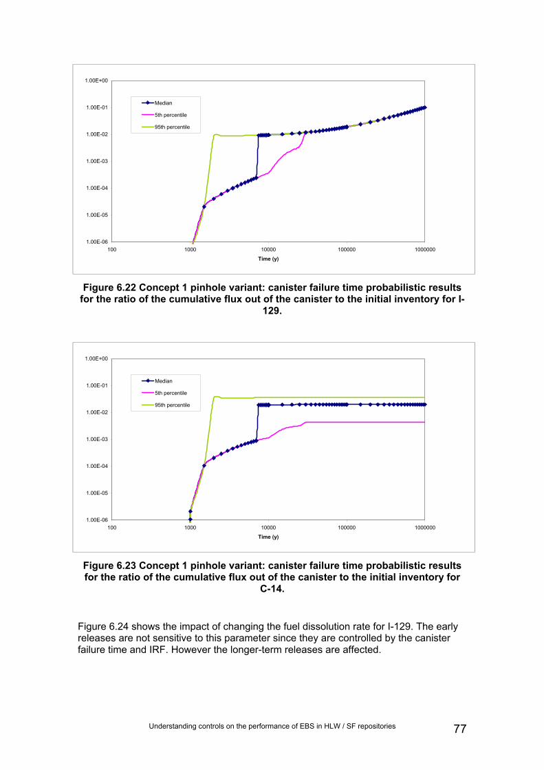
1.00E-06
1.00E-05
1.00E-04
1.00E-03
1.00E-02
1.00E-01
1.00E+00
100 1000 10000 100000 1000000
Time (y)
Median
5th percentile
95th percentile
Figure 6.22 Concept 1 pinhole variant: canister failure time probabilistic results for the ratio of the cumulative flux out of the canister to the initial inventory for I-
129.
1.00E-06
1.00E-05
1.00E-04
1.00E-03
1.00E-02
1.00E-01
1.00E+00
100 1000 10000 100000 1000000
Time (y)
Median
5th percentile
95th percentile
Figure 6.23 Concept 1 pinhole variant: canister failure time probabilistic results for the ratio of the cumulative flux out of the canister to the initial inventory for
C-14.
Figure 6.24 shows the impact of changing the fuel dissolution rate for I-129. The early releases are not sensitive to this parameter since they are controlled by the canister failure time and IRF. However the longer-term releases are affected.
Understanding controls on the performance of EBS in HLW / SF repositories 77

1.00E-06
1.00E-05
1.00E-04
1.00E-03
1.00E-02
1.00E-01
1.00E+00
1000 10000 100000 1000000
Time (y)
Median
5th percentile
95th percentile
Figure 6.24 Concept 1 pinhole variant: fuel dissolution rate probabilistic results for the ratio of the cumulative flux out of the canister to the initial inventory for I-
129.
Figure 6.25 shows the impact of changing the solubility limit of U, which is the only element considered to be solubility limited in Concept 1. The results show that solubility limitation is a key control on the release of U-235, with releases scaling in proportion to the change in solubility limit.
1.00E-06
1.00E-05
1.00E-04
1.00E-03
1.00E-02
1000 10000 100000 1000000
Time (y)
Median
5th percentile
95th percentile
Figure 6.25 Concept 1 pinhole variant: solubility limit probabilistic results for the ratio of the cumulative flux out of the canister to the initial inventory for U-235.
78 Understanding controls on the performance of EBS in HLW / SF repositories

Radionuclide transport through the near field (buffer, backfill and seal) was found to be insensitive to variation in distribution coefficients for the radionuclides included in the calculations. This occurred for a number of reasons:
• The radionuclide is not considered to be sorbed or is only weakly sorbed, such as I-129, Cl-36. Relative retardation (which controls the relative speed of movement of the transported radionuclide) is calculated by
ϑρ dKR += 1 . When the distribution coefficient (Kd) is small, variations in this parameter must be many times the median value to create a retardation coefficient significantly different to one.
• The half-life is short compared to canister failure time and buffer travel time so there is never any significant flux out of the buffer, such as Am-241.
• The radionuclide sorbs so strongly that it never migrates through the buffer within calculation timescales, even for the minimum distribution coefficient used, such as Zr-93.
Sorption onto the waste canister and associated corrosion products is not considered in the calculations and therefore releases from the canister are not affected by this process.
Figure 6.26 shows the impact of changing the flow rate through the near-field and host rock (geosphere) on the ratio of the cumulative flux of I-129 transported out of the buffer compared to the cumulative flux transported into the buffer. As the flow rate increases I-129 is transported more rapidly though the buffer. Had the calculations been run beyond one million years the peak values for the three curves (median, 5th and 95th percentiles) would have been similar.
With the exception of Cl-36 and C-14 equivalent plots for all the other radionuclides show almost no variation about the median. The Cl-36 response is similar to that for I-129, and the response for C-14 is shown in Figure 6.27. Up to 10,000 years there is only diffusion of C-14 out of the pinhole, and the results are the same for all realisations. The canister is assumed to fail completely at 10,000 years and advective radionuclide transport begins. The C-14 results are then sensitive to the flow rate PDF.
Understanding controls on the performance of EBS in HLW / SF repositories 79

0.00001
0.0001
0.001
0.01
0.1
1
1000 10000 100000 1000000
Time (y)
Median
5th percentile
95th percentile
Figure 6.26 Concept 1 pinhole variant: flow rate probabilistic results for the ratio of the cumulative flux out of the buffer to the cumulative flux into the buffer for I-
129.
0.00000001
0.0000001
0.000001
0.00001
0.0001
0.001
1000 10000 100000 1000000
Time (y)
Median
5th percentile
95th percentile
Figure 6.27 Concept 1 pinhole variant: flow rate probabilistic results for the ratio of the cumulative flux out of the buffer to the cumulative flux into the buffer for
C-14.
6.4.3 Conclusions from simple numerical analysis
The results of these illustrative calculations show that for SF the buffer and backfill are secondary barriers to contaminant transport, except for radionuclides that are strongly sorbed onto the buffer and backfill materials. For key long-lived radionuclides such as I-129, the buffer and backfill act to delay release rather than reduce the flux from the EBS. The key role of the buffer and backfill is to protect the canister for as long as is required. The length of time for which canister integrity needs to be maintained depends on the EBS and geosphere system as a whole. For Concept 1, the KBS-3V
80 Understanding controls on the performance of EBS in HLW / SF repositories

type concept aims to maintain canister integrity for as long as possible because the host rock (geosphere) is a relatively poor barrier, while Concept 2, the Andra type concept, only aims to maintain canister integrity during the early heat-generating phase when the majority of the inventory decays.
Understanding controls on the performance of EBS in HLW / SF repositories 81

7 Discussion of controls on repository performance
7.1 Differences between HLW and SF The main focus of the work reported here concerns controls on the performance of repositories for HLW and SF. However, the calculations described in Section 6 were run for SF. Key differences between the characteristics of HLW and of SF that could be reflected in controls on the performance of repositories for these wastes are:
• the presence of an IRF in SF, but not in HLW;
• different inventories of radionuclides in SF and HLW (the former containing a greater proportion of longer-lived radionuclides);
• differing dissolution rates of waste forms containing SF and HLW.
These different characteristics are reflected principally in different:
• rates of radionuclide release following canister failure;
• thermal evolution of the waste (notably expressed in different peak temperatures and different timing of peak temperatures);
• radiation fluxes at any particular time.
HLW is derived from the radioactive liquid produced during reprocessing of SF and is typically in the form of glass. HLW therefore contains the majority of fission products present in SF. In contrast, SF is present dominantly in the form of metal, metal oxides (such as UO2 assemblies) and metallic claddings (which may have varied compositions in different kinds of fuel). These different characteristics are reflected in different heat outputs and radionuclide release characteristics from the different kinds of waste. For example, in the Swiss concept for disposal of HLW and SF in the Opalinus Clay, SF canisters containing only UO2 assemblies, or UO2 and MOX (mixed oxide) fuel assemblies each have an initial heat output restricted to 1,500 W per canister (Johnson et al. 2002). However, the heat output of the UO2/MOX canisters decreases more slowly, because there are greater quantities of Pu present. In contrast, HLW canisters contain less actinide than SF canisters and hence the initial heat output of HLW canisters is only around 700 W/canister. Additionally, this heat output decreases more rapidly than the heat output of either kind of SF canister.
The different physical characteristics of HLW and SF place different constraints on the maximum temperatures that are acceptable following repository closure. In the Swiss concept the HLW glass is required to remain below 500°C to prevent devitrification while SF cladding temperatures must be below 350°C to avoid the possibility of creep, thereby causing rupturing.
82 Understanding controls on the performance of EBS in HLW / SF repositories

7.2 Implications of whole repository upscaling Some of the threats to the safety functions identified in Sections 4 and 5 will affect the entire repository, whereas others will tend to impact on a small subsection of the repository or just a single canister (Table 7.1).
The calculations in Section 6 were done for a single canister. However, the results are presented as the proportion of each radionuclide that is retained by each barrier as a function of time. Consequently, the applicability of the results to an entire repository depends on whether the release process is likely to operate at the repository scale.
The degree to which each calculation applies to the whole repository is summarized in
Table 7.1. The base case of each calculation concerns normal (expected) evolution of a single canister. In
Table 7.1, we have assumed that all waste canisters behave similarly and therefore the calculated proportion of each radionuclide that is retained in each barrier is applicable not only for a single canister, but also for an entire repository. In contrast, the variant calculation cases are applicable to greater or lesser degrees to the scale of the full repository, depending on the assumptions for that case.
In the case of buffer erosion and canister corrosion, the release process would reflect the heterogeneous spatial distributions of groundwater flow pathways in the host rock. Buffer erosion and hence corrosion would occur only adjacent to relatively transmissive structural features in the rock mass, such as a fracture zone. Consequently, this process is not relevant for an entire repository.
Similarly, canister shearing would be controlled by structural heterogeneities in the host rock. This process would most likely occur only in the unlikely event that some pre-existing fracture underwent movement.
A growing pinhole in a canister would normally affect a small number of canisters. Most likely, this would be the case where pinhole development reflects manufacturing defects in the canister. However, this process might affect a large number of canisters, or all the canisters in a repository eventually. Potentially, both circumstances could affect a repository at different times. At earlier times, manufacturing defects could cause pinhole development in a small number of canisters. At later times, pinholes might develop in most of the remaining canisters.
Seal failure can have consequences for the entire repository or only subsections depending upon how many seals fail and where they fail. If the seal fails because of heterogeneities in the host rock or due to quality control issues, only a small proportion of a repository is likely to be affected, probably in the earlier stages. Eventually all seals could fail, in which case the entire repository would be affected.
In the case of poor buffer performance, or canister corrosion/failure occurring early, the effects on radionuclide release are likely to affect only a small proportion of the repository. A poor buffer throughout the repository would imply a systematic lack of quality control, and/or inferior buffer design. Sufficient work has been conducted to conclude that such scenarios are highly unlikely to occur. A similar argument may be used to conclude that early canister corrosion/failure is unlikely to occur throughout a repository.
Understanding controls on the performance of EBS in HLW / SF repositories 83

Table 7.1 Summary of the regions within a repository to which the calculation variants in Section 6 apply.
Concept 1 Concept 2 Concept 3 Concept 4 Calculation case Strong fractured host rock with KBS-3V type concept
Mudrock with clay buffer
Mudrock with supercontainer and cement buffer
Salt with salt backfill
Base case Whole repository Whole repository Whole repository Whole repository Growing pinhole If related to
construction defects, likely to affect a few canisters; will affect all canisters eventually
Not calculated Not calculated Not calculated
Buffer erosion and canister corrosion
Likely to affect a few canisters
Not calculated Not calculated Not calculated
Canister shearing
Likely to affect a few canisters
Likely to affect a few canisters
Not calculated Not calculated
Seal failure
Not calculated Could affect individual tunnels of the entire repository
Not calculated Not calculated
Poor buffer Not calculated Could affect a range of repository scales e.g. a single emplacement, an entire tunnel, or even the entire repository (although this is unlikely since it implies poor quality control throughout repository lifetime).
Not calculated Not calculated
Early canister corrosion/failure
Not calculated Not calculated Not calculated Most likely to affect a few canisters, but could affect the whole repository. Small possibility that a large enough brine pocket could impact on the whole facility.
In terms of the calculations conducted here, no distinction is made between the release associated with a spatial cluster of a small number of failed canisters and the same number of canisters failing in a non-spatially correlated fashion. This work focussed on the degree to which quantities of radionuclides are retained in each part of the disposal system. If an assessment were conducted where likely concentrations of radionuclides in the disposal system and geosphere were important (such as for contaminated drinking water calculations), serious consideration would have to be given to representing this spatial distribution, as discussed above. Temporal clustering, for example canister failure time, might also be important, depending on the distribution of failure times envisaged. However for the purposes of our calculations it is sufficient to highlight this inevitable simplification and emphasise the need to consider spatial
84 Understanding controls on the performance of EBS in HLW / SF repositories

clustering effects, and temporal distributions of failures, when conducting a more complete assessment.
7.3 Key controls and the relationship to FEPs FEPs from the NEA’s FEP list that could potentially affect repository performance can be deduced from:
• the review in Section 3 of disposal concepts proposed for HLW and SF;
• the review and analysis of safety functions in Section 4;
• the review and audit of FEPs associated with these concepts in Section 5.
These FEPs are given in Table 7.2 and can be grouped according to the underlying controls on EBS - host rock system performance influenced directly by each FEP. The identification of these controls is somewhat subjective, but the number of alternative classifications of underlying controls will increase as the number of controls increases. On the other hand, the number of defined performance indicators should be sufficiently large that underlying physical, chemical and radiological controls are distinguished, thereby relating to the kinds of safety arguments that would need to be developed. Consequently, the approach to defining performance controls taken here was:
• to define performance controls to minimize duplication of underlying chemical, physical and radiological processes and characteristics among different controls;
• to ensure the set of performance controls corresponds to a minimal number of safety arguments, using for guidance the kinds of safety arguments made in radioactive waste management programmes throughout the world.
This approach resulted in the following eleven controls being identified:
• (1) chemical stability of engineered barriers;
• (2) physical stability of engineered barriers;
• (3) chemical environment of the EBS;
• (4) groundwater flow characteristics;
• (5) deformation characteristics of the host rock;
• (6) waste characteristics;
• (7) transport characteristics in the host rock;
• (8) structure of the host rock;
• (9) thermal conditions in the geosphere;
• (10) thermal conditions in the EBS;
• (11) radioactive decay and in-growth.
Understanding controls on the performance of EBS in HLW / SF repositories 85

Table 7.2 Subset of FEPs from the NEA (2000) International FEP list that could exert an influence on repository performance.
FEP Control FEP Control1.1.03 Emplacement of wastes and
backfilling 1 + 2
2.1.12 Gas sources and effects
(in wastes and EBS) 1 + 2
1.1.04 Closure and repository sealing
1 + 2
2.1.13 Radiation effects (in wastes and EBS)
1 + 2 + 6
1.1.07 Repository design 1 + 2
2.2.01 Excavation disturbed zone/host rock
5
1.1.08 Quality control 1 + 2 2.2.02 Host rock 3 + 4 + 5
1.1.09 Schedule and planning 1 + 2
2.2.04 Discontinuities, large scale (other)
8
1.2.02 Deformation, elastic, plastic or brittle
2 + 4 + 5
2.2.05 Contaminant transport path characteristics (in geosphere)
3 + 4 + 8
1.2.03 Seismicity 3 + 4 + 5
2.2.06 Mechanical processes and conditions (in geosphere)
5
1.2.09 Salt diapirism and dissolution 3 + 5
2.2.07 Hydraulic/hydrogeological processes and conditions (in geosphere)
4
1.2.10 Hydrological/hydrogeological response to geological changes
4
2.2.08 Chemical/geochemical processes and conditions (in geosphere)
3
1.3.07 Hydrological/hydrogeological response to climate changes
4
2.2.10 Thermal processes and conditions (in geosphere)
9
2.1.01 Inventory, radionuclide and other material
6
2.2.11 Gas sources and effects (in geosphere)
3 + 4
2.1.02 Waste form materials and characteristics
1 + 2
3.1.01 Radioactive decay and in-growth
11
2.1.03 Container materials and characteristics
1 + 2
3.2.01 Dissolution, precipitation and crystallisation, contaminant
3 + 7
2.1.04 Buffer /backfill materials and characteristics
1 + 2
3.2.02 Speciation and solubility, contaminant
3 + 7
2.1.05 Seals cavern/tunnel/shaft 1 + 2
3.2.03 Sorption/desorption processes, contaminant
3 + 7
2.1.06 Other engineered materials features and characteristics
1 + 2
3.2.04 Colloids, contaminant interactions and transport with
3 + 7
2.1.07 Mechanical processes and conditions (in wastes and EBS)
2
3.2.05 Chemical/complexing agents, effects on contaminant speciation/transport
3 + 7
2.1.08 Hydraulic/hydrogeological processes and conditions (in wastes and EBS)
7
3.2.06 Microbial/biological/plant-mediated processes, contaminant
3 + 7
2.1.09 Chemical/geochemical processes and conditions (in wastes and EBS)
3
3.2.07 Water-mediated transport of contaminants
4 + 7
2.1.11 Thermal processes and conditions (in wastes and EBS)
10
86 Understanding controls on the performance of EBS in HLW / SF repositories

Understanding controls on the performance of EBS in HLW / SF repositories 87
7.4 Characteristics of concepts that affect the relative importance of controls
In any of the generic concepts, all the considered (unscreened) FEPs would exert some influence on repository performance, although the relative importance of the different FEPs would depend upon site-specific characteristics, many of which were not considered here as they were outside the scope of the report. For example, in the UK it is possible that FEP “1.3.07 Hydrological/hydrogeological response to climate changes” would be more significant in areas likely be glaciated in future (in Wales and more northerly parts of England) than in areas less likely to be glaciated (in southerly parts of England).
The potential influences of geological environments and concepts on important repository performance controls are given in Table 7.3. These influences can be mapped to important controlling FEPs drawn from the NEA’s international FEP list (NEA, 2000), in Table 7.2. These FEPs can then be mapped to the safety functions of the various concepts via Table B.3. to Table B.6. The ways in which these safety functions influence interactions between EBS components can then be seen in Table 5.2 to Table 5.5.

Table 7.3 Characteristics of disposal concepts that affect key underlying controls on repository performance given in Section 7.3.
Shorter-lived waste package/overpack – clay buffer
Longer-lived waste package/overpack – clay buffer
Shorter-lived waste package/overpack – clay buffer
Shorter-lived waste package/overpack – cement buffer
Shorter-lived waste package/overpack – no buffer
Shorter-lived waste package/overpack – no buffer Control
Hard fractured rock
Hard fractured rock
Mudrock Mudrock Mudrock Bedded evaporite
1 Chemical stability of engineered barriers
Chemical heterogeneity related to transmissive fracture distribution
Chemical heterogeneity related to transmissive fracture distribution
Reactive constituents of host rock (especially clays on which cation exchange may occur, sulphides, organics)
High-pH from cement; reactive constituents of host rock (especially clays on which cation exchange may occur, sulphides, organics)
Reactive constituents of host rock (especially clays on which cation exchange may occur, sulphides, organics)
Highly saline porewater/ groundwater
2 Physical stability of engineered barriers
Host rock may undergo brittle deformation; presence of fractures
Plastic deformation of buffer
Host rock may undergo brittle deformation; presence of fractures
Plastic deformation of buffer
Host rock may deform plastically
Plastic deformation of buffer
Host rock may deform plastically
Brittle deformation of buffer
Host rock may deform plastically
Host rock deforms plastically
3 Chemical environment of the EBS
Chemical heterogeneity related to transmissive fracture distribution
Chemical heterogeneity related to transmissive fracture distribution
Reactive constituents of host rock (especially clays on which cation exchange may occur, sulphides, organics)
Reactive constituents of host rock (especially clays on which cation exchange may occur, sulphides, organics)
Reactive constituents of host rock (especially clays on which cation exchange may occur, sulphides, organics)
Highly saline porewater/ groundwater
4 Groundwater flow characteristics
Dominantly advective transport
Dominantly advective transport
Dominantly diffusive transport
Dominantly diffusive transport
Dominantly diffusive transport
Dominantly diffusive transport
88 Understanding controls on the performance of EBS in HLW / SF repositories

Shorter-lived waste package/overpack – clay buffer
Longer-lived waste package/overpack – clay buffer
Shorter-lived waste package/overpack – clay buffer
Shorter-lived waste package/overpack – cement buffer
Shorter-lived Shorter-lived waste waste package/overpack package/overpack – no buffer – no buffer Control
Hard fractured rock
Hard fractured rock
Mudrock Mudrock Mudrock Bedded evaporite
5 Deformation characteristics of the host rock
Host rock may undergo brittle deformation; presence of fractures
Host rock may undergo brittle deformation; presence of fractures
Host rock may deform plastically OR undergo brittle deformation, depending upon particular mudrock
Host rock may deform plastically OR undergo brittle deformation, depending upon particular mudrock
Host rock may deform plastically OR undergo brittle deformation, depending upon particular mudrock
Plastic deformation; no fracturing
6 Waste characteristics No specific characteristic
No specific characteristic
No specific characteristic
No specific characteristic
No specific characteristic
No specific characteristic
7 Transport characteristics in the host rock
Frequency and transmissivities of fractures in host rock
Frequency and transmissivities of fractures in host rock
Low-permeability host rock; no advective flow paths
Low-permeability host rock; no advective flow paths
Low-permeability host rock; no advective flow paths
Low-permeability host rock; no advective flow paths
8 Structure of the host rock Fractures in host rock
Fractures in host rock
No significant brittle deformation
No significant brittle deformation
No significant brittle deformation
No significant brittle deformation
9 Thermal conditions in the geosphere
No specific characteristic: differing hard fractured rocks may have widely different thermal conductivities – generally increase with increasing silica contents
No specific characteristic: differing hard fractured rocks may have widely different thermal conductivities – generally increase with increasing silica contents
Relatively low host rock thermal conductivity
Relatively low host rock thermal conductivity
Relatively low host rock thermal conductivity
Relatively high host rock thermal conductivity
Understanding controls on the performance of EBS in HLW / SF repositories 89
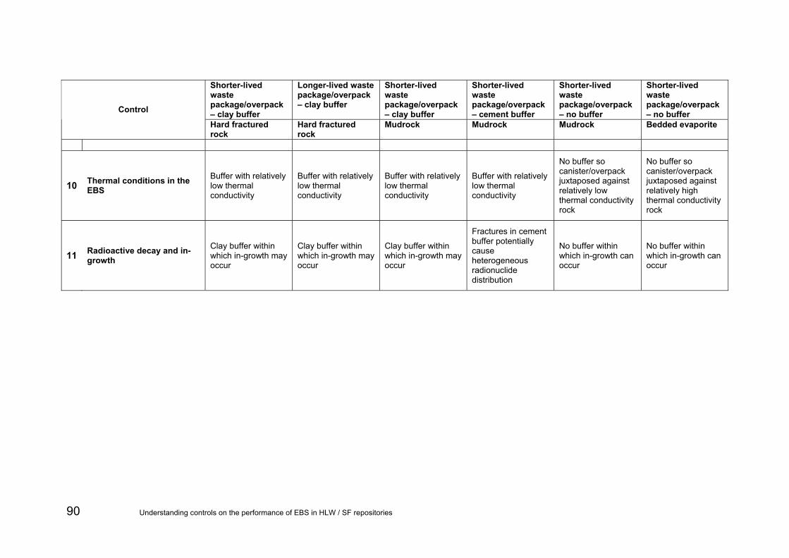
90 Understanding controls on the performance of EBS in HLW / SF repositories
Shorter-lived waste package/overpack – clay buffer
Longer-lived waste package/overpack – clay buffer
Shorter-lived waste package/overpack – clay buffer
Shorter-lived waste package/overpack – cement buffer
Shorter-lived waste package/overpack – no buffer
Shorter-lived waste package/overpack – no buffer Control
Hard fractured rock
Hard fractured rock
Mudrock Mudrock Mudrock Bedded evaporite
10 Thermal conditions in the EBS
Buffer with relatively low thermal conductivity
Buffer with relatively low thermal conductivity
Buffer with relatively low thermal conductivity
Buffer with relatively low thermal conductivity
No buffer so canister/overpack juxtaposed against relatively low thermal conductivity rock
No buffer so canister/overpack juxtaposed against relatively high thermal conductivity rock
11 Radioactive decay and in-growth
Clay buffer within which in-growth may occur
Clay buffer within which in-growth may occur
Clay buffer within which in-growth may occur
Fractures in cement buffer potentially cause heterogeneous radionuclide distribution
No buffer within which in-growth can occur
No buffer within which in-growth can occur

7.5 Interactions between disposal system components
In this section, a summary is provided of the most important interactions between components of the system. This summary is based on the issues from Table 5.2 to Table 5.5, together with the calculations presented in Section 6.
7.5.1 Importance of interactions between wastes and EBS
The only major impact from wastes on the EBS is thermal. Spent fuel and HLW produce large quantities of heat (up to several kW per canister initially) and so raise the temperature of the EBS. Each international programme has looked at this issue and chosen a canister separation distance and repository layout that prevents temperatures from reaching damaging levels (see for example SKB, 2006a). Too high temperatures could lead to alteration of the buffer and/or interfere with buffer resaturation and hence impact on buffer performance. In the calculations presented here, we have assumed this does not happen. Calculations to support a similar conclusion should be presented for any chosen design and site.
The EBS is designed to perform two safety functions. First, it prevents any release for a period of time, long enough for short-lived nuclides to decay away to insignificant levels. Once this primary containment function fails, the role of the EBS is to limit release of the radionuclides. This is achieved by limiting groundwater access and providing a suitable and stable chemical environment. For different concepts, the period of complete containment varies. Requirements are largely determined by characteristics of the host rock; a fractured hard rock environment may provide less of a barrier function than a mudrock and so more reliance is placed on the EBS and canister. However, in practice there are few important nuclides with half-lives in the range where increasing canister lifetime from 1,000 to 100,000 years has a significant effect on inventory at the time of canister failure. An exception is C-14, where Figure 6.23 shows that increasing canister lifetime can reduce releases.
The second function of providing a suitable and stable chemical environment is key. The slow dissolution of SF or glass and solubility constraints on some nuclides are important controls. Figure 6.24 shows that fuel dissolution rate has a strong effect even for I-129, when one might expect the IRF to dominate. Figure 6.25 shows that the solubility of uranium directly controls the release of uranium isotopes. Note that the fraction of uranium released over a million-year period is a very small, emphasising the role of the chemically controlled properties.
7.5.2 Importance of interactions between EBS components
The key interaction between EBS components is between the buffer and the canister. In the salt concept, the backfill plays an equivalent role to the buffer in other cases. The buffer protects the canister from failure by limiting groundwater access, by controlling the chemistry and by acting as physical protection against mechanical disruption. Its main role is to limit corrosion. For the shorter-lived (steel) canisters, a reducing environment and zero or low flow is important; for the salt case the actual amount of water is limited and for the supercontainer the high pH plays a role. For the longer-lived (copper) canister corrosion will be extremely slow under the naturally reducing conditions that will occur following closure and the processes that could
Understanding controls on the performance of EBS in HLW / SF repositories 91

potentially lead to corrosion are different. If it occurs, a key process would be reaction between the canister and sulphide, which could be microbially produced. Thus, the buffer has an important role in preventing microbial access to the canister. Rock shearing is another threat to canister integrity, largely for the longer-lived canisters, and the buffer is expected to mitigate small movements. As Figure 6.9 shows, shearing has the potential to enhance releases if canister failure and opening up of a transport path are linked.
Interactions between the buffer and backfill are limited. The role of the backfill is to prevent voidage that could lead to flow enhancement and loss of compaction for the buffer. A calculation for the mudrock with clay buffer showed that a poor buffer is not necessarily significant. However, for the long-lived canister a poorly compacted buffer could undermine the safety functions by allowing corrosion and enhancing release.
7.5.3 Importance of interactions between EBS and geosphere
The EBS is initially in disequilibrium with the geosphere, chemically and hydraulically, and so there will be an initial period of strong interaction. Thus, the EBS design must be matched to the geosphere properties. Adequate design will mean that the EBS meets its safety functions after the transient phase is over. This interaction is a key control on EBS behaviour, as it is the most significant threat to the design performance.
The thermal interaction is also important. Heat produced by waste is ultimately carried away by conduction in the geosphere and the thermal properties of the host rock should be sufficiently well characterised. This is particularly the case for a design being optimised to minimise its footprint, when thermal effects will be a key constraint.
When conditions in the geosphere change, these can impact the EBS. The most notable example is the buffer erosion case for the long-lived canister concept, developed by SKB. If dilute (low-calcium) groundwater reaches repository depth (during an episode of glacial melting) the buffer can become unstable and erode, leaving the canister exposed and liable to corrode. With the buffer gone, any releases are direct to the geosphere. The probability of this scenario occurring in England and Wales is lower than in more northerly countries, owing to the reduced likelihood of glaciations in England and Wales. However, this scenario is indicative of natural processes that can influence long-term engineering material performance.
Shear movement on faults in the geosphere have the potential to damage EBS components. An understanding of the fault structure of the host rock should minimise this threat, but this understanding is not easy to obtain.
In general, the stability of the geosphere is a key control on the EBS performance.
The other interaction with the geosphere is that it provides boundary conditions for the movement of radionuclides. A diffusive geosphere will greatly limit release. A fractured geosphere limits release in a different way, by only having small areas of flowing water in contact with the EBS. Clearly a more permeable porous host rock would not limit release as effectively, as the extremely high transport resistance effects associated with diffusing radionuclides to a small number of fractures would not apply – diffusion would only be limited by the radionuclide diffusivity in the buffer.
92 Understanding controls on the performance of EBS in HLW / SF repositories

7.5.4 Importance of interactions between the EBS and radionuclide transport
The role of the EBS in limiting radionuclide transport once released from the canister is less significant than is sometimes supposed. Figure 6.12 shows limited delays to release provided by the buffer. In general buffers and backfill are only metres in scale and so diffusive timescales are likely to be relatively short compared to potential delays in the geosphere.
The key role of the EBS in radionuclide transport is to limit it at source –initially by total containment and later by controlling the release rate from the waste.
7.6 Other controls on repository performance This work has focussed on identifying the most important direct controls on the performance of the EBS. However, there are other controls which, though strictly outside the scope of this project, may nevertheless impact upon repository performance. These controls may be divided into the following groups:
• controls related to the context of a repository programme (including regulatory and political factors that influence repository siting and design);
• controls related to the overall geological setting of a repository;
• controls related to future environmental climatic changes;
• controls related to future human activities (and human intrusion).
The first of these controls will influence whether there is implementation of any of the concepts in Table 3.7 that are considered to be over-engineered.
The second control recognizes the fact that the EBS and surrounding host rock do not exist in isolation from other geological features. For example, the immediate repository environment will depend partly upon whether there are cover rocks above the host formation and the characteristics of any cover rocks. If a hard fractured host rock extends to the surface, any safety case is likely to place greater emphasis on the EBS than if there is a low-permeability cover sequence above the host rock (Metcalfe and Watson, 2009). Similarly, the characteristics of groundwater flow (directions and fluxes) and groundwater chemistry (notably salinity) will depend on the general geological setting of the repository. For instance, highly saline groundwater may migrate into any kind of host rock from nearby halite-bearing sedimentary rock sequences.
The impacts of future climatic changes are also likely to depend partly on the location of the repository. For example, more southerly locations are less likely to be glaciated in the future than are more northerly locations. Similarly, higher-altitude inland locations are less likely to be submerged during marine transgressions than low-lying coastal locations. While it is probable that neither glaciations nor changes in sea level will have negative impacts on repository performance, it will be necessary to prove this; such demonstration will require some understanding of the potential ways in which these environmental changes might impact upon the EBS.
Human intrusion is a potential impact upon an EBS which would inevitably be negative. The potential for this occurring would need to be minimised by suitable repository siting and “signposting” of the repository.
Understanding controls on the performance of EBS in HLW / SF repositories 93

7.7 Implications for other wastes The characteristics of other wastes may have widely varying implications for repository performance. The physical characteristics of the wastes and the ways in which they are packaged/encapsulated will be major controls, as will the presence and characteristics of any IRF, the radionuclide inventory, and solubility of the wastes. It will be necessary to assess the implications of these controls on a case-by-case basis, taking into account the nature of the disposal concept to be implemented.
DETR (1999) set out a research and development strategy for HLW and SF disposal in the UK. As part of this study, the impact of additional wastes was considered (QuantiSci, 1999). The additional wastes considered were:
• late-arising ILW from decommissioning activities;
• depleted uranium tails from fuel enrichment and reprocessing activities;
• plutonium for reprocessing activities;
• miscellaneous wastes of small volume.
All issues for the final category were considered to be covered by the first three.
The late-arising ILW was considered important because the timing of decommissioning arisings was then thought to occur after closure of any repository constructed for HLW/SF. This waste is now best considered in the more general context of co-location.
It was suggested that depleted uranium could be used in the buffer to condition the geochemical environment.
It was concluded that the most significant impacts would be from Pu declared as waste. The issues identified largely concerned the development of a suitable waste form. The thermal impacts of Pu waste would be longer term than for HLW or SF and could require design or layout changes. Similarly, criticality and safeguard issues would have to be considered; deep borehole disposal might be necessary.
Thus, key controls do not seem to be affected by consideration of other wastes, but the need to develop new waste forms or modify designs could affect the knowledge base supporting associated safety cases. Deep boreholes have not been considered here.
In the case of higher burn-up wastes, there will be higher levels of fission products with relatively short half-lives, particularly Cs-137 and Sr-90 than in lower burn-up fuel. As a result, a specified quantity of higher burn-up SF will produce greater heat soon after closure than would the same quantity of SF from a lower degree of burn-up.
Possible direct disposal of Magnox SF would raise a number of performance-related issues, principally due to the propensity for Magnox to corrode. If Magnox fuel is encapsulated in cementitious grout, corrosion of U may continue until all the free water in the grout has been consumed, which may cause storage problems. Waste packages may also fail relatively soon following closure. The physical degradation of the Magnox may also be detrimental to the chemical barrier. Corrosion of Magnox will also result in H2 gas generation in the repository. Depending upon the disposal concept, this may be an issue for repository gas pressures, resaturation behaviour, pressures across seals and also bulk gas pressure driving C-14 labelled gas transport.
This report has not considered SF that may arise from possible new-build reactors. The precise implications of these wastes for repository performance will be highly
94 Understanding controls on the performance of EBS in HLW / SF repositories
dependent upon the nature of the new-build reactors, the encapsulation methods, the storage conditions and the disposal concept that is chosen.
7.8 Implications for co-location DETR (1999) also considered co-location of a cementitious repository for ILW, as did the supporting report (QuantiSci, 1999).
The issues identified included the potential for thermal and chemical interactions and design implications in terms of sealing, retrieval and safeguards.
Clearly, a cementitious repository has the potential to generate a high pH plume in the geosphere that might adversely impact on the chemical environment for a HLW/SF repository, although the geosphere would act as a pH buffer in most situations. The likelihood of such an interaction will depend on details of the layout and design as well as the hydrogeological properties of the host rock. Clearly an ILW repository should be down-gradient (hydraulically) from a HLW/SF repository, but early flow patterns during resaturation would need to be carefully analysed.
The impact of the temperature rise for an ILW repository could be minimised by ensuring a suitable separation distance (on the order of several hundred metres).
7.9 Knowledge limitations Much is known about the fundamental physical and chemical processes that underlie the controls on repository performance identified in the previous sections. However, to predict how these controls will operate at any particular site will require site-specific information and data.
There are several areas where better fundamental understanding is required, in addition to site-specific information, concerning:
• confirmation of the mechanisms of canister failure;
• coupled processes in the early phase of repository evolution, during the phase of high temperatures immediately following closure;
• impacts of pre-closure activities on post-closure performance (in particular the impact of EBS evolution under oxidizing conditions during any prolonged open period on post-closure performance);
• reliability of thermodynamic databases under highly saline groundwater conditions;
• behaviour of wastes other than vitrified HLW and SF.
Understanding controls on the performance of EBS in HLW / SF repositories 95

8 Summary and conclusions A combination of literature reviews and an expert workshop were used to identify key controls on repository performance. These controls were audited against the international FEP list of the NEA (NEA, 2000) to build confidence that no major issue had been omitted. The main controls were then illustrated by simple numerical simulations for four combinations of host rock and disposal concept. The simulations also shed light on the relative importance of the different controls.
Eleven main controls on repository performance were identified and their relationships to the safety functions of EBS components deduced. However, the relative importance of these different controls and their overall impact upon safety will depend upon:
• site-specific characteristics (notably rock chemistry and hydrogeological properties, forces driving groundwater flow and groundwater chemistry);
• the detailed nature of the concept to be implemented;
• the detailed repository design;
• implementation of the repository design.
The required performance of an EBS is also variable and will depend not only on technical issues connected with the EBS itself, but also on the regulatory environment, the actual wastes to be disposed and characteristics of the surrounding geosphere (outside the scope of this project).
In general, there are two aspects to the performance of each barrier component:
• containment of radionuclides;
• retardation of radionuclides.
All disposal concepts include a container for the waste. However, the function required of the container, and the performance criteria that it must meet, is different in different concepts. Where employed, the primary function of a buffer is to protect the canister and the retardation of radionuclides is only of secondary importance.
Some controls on performance will affect an entire repository, whereas other controls will affect only a single canister or a small number of canisters. In this latter case, it is difficult to demonstrate how many canisters may be affected by a particular control. As a result it may be difficult for proponents of a repository to provide safety arguments.
An important implication for EBS design is that it must meet regulatory requirements by working together with the geological environment in which it is to be emplaced. Thus, in the absence of information about the regulatory context and specific geological environment where a repository is to be sited, it is not possible to determine the optimum waste form, waste packaging and repository design. Conversely, it is quite conceivable that more than one design could achieve adequate performance in any particular geological environment.
The illustrative calculations show that for SF the buffer and backfill are secondary barriers to contaminant transport, except for radionuclides that sorb strongly onto the buffer and backfill materials. For certain long-lived radionuclides such as I-129 the buffer and backfill only delay release, rather than reduce the flux from the EBS. The main role of the buffer and backfill is to protect the canister for the period required to meet safety targets. Thus, canister integrity will need to be maintained for a period that depends upon the EBS and geosphere system as a whole.
96 Understanding controls on the performance of EBS in HLW / SF repositories
The calculations also show that the influence on radionuclide release of canister failure time and groundwater flow through the EBS depends upon the half-life and chemical characteristics of the radionuclides considered. An implication is that packaging needs to be carefully matched to the nature of the wastes and the repository concept that is implemented. In the case of legacy wastes that have already been packaged (primarily ILW) it will be necessary to design a barrier system that will perform adequately given the characteristics of existing packaging; re-packaging of most wastes is likely to prove infeasible.
All barriers employed in a particular EBS will interact with one another physically and chemically to some degree. These barriers will also interact chemically and physically with the host rock. Three kinds of interaction in particular could have adverse consequences for barrier performance:
• interactions between highly saline groundwater and barrier components;
• extrusion/loss of buffer into transmissive features of a rock mass;
• interactions between any cementitious barriers and clays in the EBS and/or host rock.
The first of these could occur in any kind of host rock lithology, but will certainly occur in halite host rocks. Whether highly saline waters occur in other kinds of host rock will depend upon the geological setting (for example, whether there is a halite-bearing sedimentary basin nearby as a source of highly saline water). While not necessarily disadvantageous for performance, a complicating factor is that predictive chemical models tend to be less reliable in highly saline groundwater systems than in fresher systems. Consequently, it may prove harder to justify safety arguments.
Extrusion/loss of buffer material into transmissive features of the rock mass is most likely to be a difficulty when siting a repository in hard fractured rock or sedimentary rocks. However, the possibility of this process having major effects could be eliminated by emplacing waste canisters in unfractured volumes of the host rock.
Negative effects of interactions between cementitious and clay components of any EBS, or between cementitious components and a clay host rock, chiefly concern clay alteration. There could be localised increases in clay porosity and, in the case of bentonite buffers, a loss of swelling capacity. However, these effects are to some extent counter-balanced by interactions that are potentially positive for safety. Notably, the cement will produce an alkaline environment in which rates of metal corrosion are reduced.
Understanding controls on the performance of EBS in HLW / SF repositories 97

References ABRAITIS, P.K., McGRAIL, B. P., TRIVEDI, D.P., LIVENS, F.R. and VAUGHAN, D.J., 2000. Single-pass flow-through experiments on a simulated waste glass in alkaline media at 40°C.: II. Experiments conducted with buffer solutions containing controlled quantities of Si and Al. Journal of Nuclear Materials, 280, 206-215.
ALHEID, H.J., ARANYOSSY, J.F., BLUMLING, P., HOTEIT, N. AND VAN GEET, M., 2005. EDZ development and evolution – State of the art report for Component 4 of NF-PRO project.
ATOMIC ENERGY OF CANADA LIMITED (AECL), 1994. Environmental Impact Statement (EIS) on the Concept for Disposal of Canada’s Nuclear Fuel Waste. Atomic Energy of Canada Limited Report No. AECL-10711, COG 93-1, Ottawa.
AGENCE NATIONALE POUR LA GESTION DES DECHÉTS RADIOACTIFS (ANDRA), 2005a. Dossier 2005: Synthesis Report, Evaluation of the Feasibility of a Geological Repository, Meuse/Haute-Marne Site (English translation of the original “Dossier 2005 Argile” documentation written in French). ANDRA Report Series, Dossier 2005 Argile, Andra, Paris, 241pp.
AGENCE NATIONALE POUR LA GESTION DES DECHÉTS RADIOACTIFS (ANDRA), 2005b. Dossier 2005 Granite: Assets of Granite Formations for Deep Geological Disposal Document du Synthèsis. Andra, Paris.
AGENCE NATIONALE POUR LA GESTION DES DECHÉTS RADIOACTIFS (ANDRA) 2005c. The phenomenological evolution of a geological repository. Andra, Paris.
BALDWIN, T., CHAPMAN, N. AND NEALL, F. 2008. Geological disposal options for high-level waste and spent fuel. Galson Sciences Report to NDA RWMD. 118pp.
BAUER, C., PÉPIN, G. AND LEBON P., 2004. EDZ in the performance assessment of the Meuse/Haute-Marne site: Conceptual model used and questions addressed to the research program. Proceedings of the European Commission CLUSTER EDZ Conference and Workshop on Impact of the Excavation Disturbed or Damaged Zone (EDZ) on the Performance of Radioactive Waste Geological Repositories, Luxembourg, 3-5 November 2003, European Commission Report EUR 21028 EN.
BECHTHOLD, W., SMAILOS, E., HEUSERMANN, S., BOLLINGERFEHR, W., BAZARGAN SABET, B., ROTHFUCHS, T., KAMLOT, T., GRUPA, J., OLIVELLA, S. AND HANSEN, F., 2004. Backfilling and Sealing of Underground Repositories for Radioactive Waste in Salt (BAMBUS-II Project). EU Commission, EUR 20621 EN.
BENNETT, D.G., AND GENS, R. 2008. Overview of European concepts for high-level waste and spent fuel disposal with special reference to waste container corrosion. Long-term prediction of corrosion damage in nuclear waste systems, 14-18 May 2007, USA. Journal of Nuclear Materials, 379, 1-8.
BLÜMLING, P., BERNIER, F., LEBON, F. AND MARTIN, C.D., 2007. The excavation damaged zone in clay formations time-dependent behaviour and influence on performance assessment. Physics and Chemistry of the Earth, 32, 588-599.
BOJINOV, M., HINTTALA, J., KINNUNEN, P., LAITINEN, T., LILJA, C., MÄKELÄ, K., AND SAARIO, T. 2003. Approaches chosen to predict the effect of different forms of corrosion on copper in disposal conditions of spent fuel. In: Proceedings of an International Workshop on Prediction of Long-Term Corrosion Behaviour in Nuclear Waste Systems, European Federation of Corrosion, Volume 36, 62-72.
98 Understanding controls on the performance of EBS in HLW / SF repositories

BOSSART, P., MEIER, P., MÖRI, A., TRICK, Th. AND MAYOR, J-C., 2002. Geological and hydraulic characterisation of the excavation disturbed zone in the Opalinus Clay of the Mont Terri Rock Laboratory. Engineering Geology, 66, 19-38. BROCZKOWSKI, M.E., NOËL, J.K. AND SHOESMITH, D.W. 2007. The influence of dissolved hydrogen on the surface composition of doped uranium dioxide under aqueous corrosion conditions. Journal of Electroanalytical Chemistry, 602, 8-16. DEPARTMENT FOR ENVIRONMENT FOOD AND RURAL AFFAIRS (DEFRA) AND NUCLEAR DECOMMISSIONING AUTHORITY (NDA) 2008. The 2007 UK Radioactive Waste Inventory Main Report. Defra/RAS/08.002; NDA Report NDA/RWMD/004. DEPARTMENT OF ENVIRONMENT TRANSPORT AND THE REGIONS (DETR), 1999. An R&D Strategy for the Disposal of High-Level Radioactive Waste and Spent Nuclear Fuel. UK DETR Report DETR/RAS/99.016. EMPRESA NACIONAL DE RESIDUOS RADIOACTIVOS, S.A. (ENRESA), 2001. ENRESA-2000 : Performance Assessment of a Spent Fuel repository in a granitic formation. ENRESA Report 49-IPP-L-15-01. ENRESA, Madrid. FAIRHURST, C., 1999. Rock mechanics and nuclear waste repositories. In: Saeb, S. and Francke, C. (editors), Proceedings of the international workshop on the rock mechanics of nuclear waste repositories, Vail, Colorado, 5-6 June 1999. GENS, R., BEL, J., POURBAIX, A., HÉLIE, M., WICKHAM, S.M. AND BENNETT, D.G., 2006. Corrosion Processes and the Expected Evolution of the BSC-1 Supercontainer Design for Disposal of Belgian spent fuel and HLW. NUCPERF 2006, Cadarache, France, 27-30 March, 2006. GRAMBOW, B. ET AL., 2008. NF-PRO, Understanding and Physical and Numerical Modelling of the Key Processes in the Near-Field and their Coupling for Different Host Rocks and Repository Strategies, Final Synthesis Report RTD Component 1: Dissolution and Release from the Waste Matrix. European Commission Contract Number: FI6W-CT-2003-02389. HERBERT, H-J., BECKER, D., HAGEMANN, S., MEYER, T., NOSECK, U., RÜBEL, A., MAUKE, R. AND WOLLRATH, J., 2005. Alteration of Non-Metallic Barriers and Evolution of Solution Chemistry in Salt Formations in Germany. In: NEA (2005) Engineered Barrier Systems (EBS) in the Context of the Entire Safety Case: Process Issues, Workshop Proceedings, Las Vegas, United States, 14-17 September 2004. Paris: OECD. ISBN 92-64-01313-X. INTERNATIONAL ATOMIC ENERGY AGENCY (IAEA), 2003. Radioactive Waste Management Glossary. 2003 Edition. IAEA, Vienna. 61pp.
JAPAN NUCLEAR CYCLE DEVELOPMENT INSTITUTE (JNC), 2000. H12: Project to establish the technical and scientific basis for HLW disposal in Japan. JNC Technical Report TN1410 2000-001, JNC, Tokai-mura Japan (five volumes).
JOHNSON, L.H., NIEMEYER, M., KLUBERTANZ, G., SIEGEL, P. AND GRIBI, P., 2002. Calculations of the temperature evolution of a repository for spent fuel, vitrified high-level waste and intermediate-level waste in opalinus clay. , Nagra Technical Report NTB 01-04, Nagra, Wettingen, Switzerland. 80pp.
JOHNSON, L.H., POINSSOT, C., FERRY, C. AND LOVERA, P. 2004. Estimates of the Instant Release Fraction for UO2 and MOX fuel at t = 0. European Commission SFS
Understanding controls on the performance of EBS in HLW / SF repositories 99

Project Report, Contract No. FIKW-CT-2001-20192-SFS, Nagra Technical Report NTB 04-08, Nagra, Wettingen, Switzerland.
JOHNSON, L.H., 2005. Spent Fuel Dissolution under Disposal Conditions. Synthesis of Results from the EU SFS Project. European Commission SFS Project Report, Contract No. FIKW-CT-2001-20192-SFS, Nagra Technical Report NTB 04-09, Nagra, Wettingen, Switzerland.
JOHNSON, L.H. AND SCHNEIDER, J.W., 2007. The impact of alternative spent fuel dissolution models on calculated releases from the EBS – some insights from the opalinus clay safety case. In: NEA (2007) Engineered Barrier Systems (EBS) in the Safety Case: The Role of Modelling - Workshop Proceedings, La Coruña, Spain 24-26 August 2005, OECD Nuclear Energy Agency, 2007. ISBN: 9789264006645.
KURSTEN, B. AND DRUYTS, F. 2007. Methodology to make a robust estimation of the carbon steel overpack lifetime with respect to the supercontainer design. Long-Term Prediction of Corrosion Damage in Nuclear Waste Systems, 14-18 May 2007, USA. Journal of Nuclear Materials 379:1-3(2008), p. 91-96.
MALLANTS, D., VOLCKERT, G. AND MARIVOET, J., 2005. Probability density functions for radionuclide migration properties of cementitious material and their application in safety assessment. The 10th International Conference on Environmental Remediation and Radioactive Waste Management (ICEM) September 4-8, 2005. ICEM05-1127.
METCALFE, R. AND WALKER, C., 2004. Proceedings of the international workshop on bentonite-cement interaction in repository environments. Nuclear Waste Management Organisation of Japan (NUMO) report NUMO-TR-04-05 (also published by POSIVA as Working Report 2004-25). 190pp.
METCALFE, R. AND WATSON, 2009. Technical issues associated with deep repositories for radioactive waste in different geological environments. Environment Agency Report SC060054/SR1. 224pp.
NAGRA, 2002. Project Opalinus Clay: Models, Codes and Data for the Safety Assessment. NTB 02-06.
NATIONALE GENOSSENSCHAFT FÜR DIE LAGERUNG RADIOAKTIVER ABFÄLLER (NAGRA), 1994. Kristallin-1 Safety Assessment Report. Nagra Technical Report 93-22. 430pp.
NATIONALE GENOSSENSCHAFT FÜR DIE LAGERUNG RADIOAKTIVER ABFÄLLER (NAGRA), 2002. Project Opalinus Clay: Safety Report. Demonstration of disposal feasibility (Entsorgungsnachweis) for spent fuel, vitrified high-level waste and long-lived intermediate-level waste. Nagra Technical Report NTB 02-05. 472pp.
NUCLEAR ENERGY AGENCY (NEA), 2000. Feature, events and processes (FEPs) for geologic disposal of radioactive wastes: an international database. OECD. Paris.
NUCLEAR ENERGY AGENCY (NEA), 2003. Engineered barrier systems and the safety of deep geological repositories: state-of-the-art report. Organisation for Economic Cooperation and Development (OECD) Paris. ISBN 92-64-18498-8.
NUCLEAR ENERGY AGENCY (NEA), 2005. Engineered Barrier Systems (EBS) in the Context of the Entire Safety Case: Process Issues. Workshop Proceedings, Las Vegas, United States, 14-17 September 2004. ISBN 92-64-01313-X. OECD. Paris.
NUCLEAR ENERGY AGENCY (NEA), 2007. Engineered Barrier Systems (EBS) in the Safety Case: Design Confirmation and Demonstration, Workshop Proceedings, Tokyo, Japan, 12-15 September 2006. OECD. Paris.
100 Understanding controls on the performance of EBS in HLW / SF repositories

ONDRAF/NIRAS, 2002. Safety Assessment and Feasibility Interim Report 2. Ondraf Report No. NIROND 2001-05F.
ONDRAF/NIRAS, 2007. The Ondraf-Niras Long-Term Safety Strategy for the Disposal of High Level Waste. SFC Level 4 Report: First Full Draft. Belgian agency for radioactive waste and enriched fissile materials. ONDRAF/NIRAS Report NIROND-TR 2006–04E. 90pp.
ONDRAF/NIRAS, 2008. Evolution of the Near-Field of the Ondraf-Niras Repository Concept for Category C Wastes, First Full Draft. NIROND-TR 2007-07E.
POSIVA, 2007. Safety Assessment for a KBS-3H Spent Nuclear Fuel Repository at Olkiluoto, Summary Report. POSIVA Report 2007-06. ISBN 978-951-652-154-4, ISSN 1239-3096.
QuantiSci, 1999. High-level waste and spent-fuel disposal research strategy: Task 2.5, Impact of additional wastes on the research requirements and strategy. QuantiSci Report to the DETR, RW 8/18/12-TR-14 Version 3. 46pp.
ROLLIN, S., SPAHIU, K. AND EKLUND, U.B., 2000. Determination of dissolution rates of spent fuel in carbonate solutions. Radiochimica Acta, 88, 739-749.
SAARIO, T., 2006. Stress Corrosion Analysis of Copper – Progress Report 2006. VTT Research Report No. VTTR1121106.
SAVAGE, D. AND STENHOUSE, M.J., 2002. SFR 1 Vault Database. Statens Kärnkraftinspektion (SKI) Report 02:53. 52pp.
SAVAGE, D., BENNETT, D.G., APTED, M., SÄLLFORS, G., SAARIO, T. AND SEGLE, P., 2008. International Expert Review of SR-Can: Engineered Barrier Issues. Statens Kärnkraftinspektion (SKI) Report 08:10.
SPAHIU, K., WERME, L. AND EKLUND, U. B. 2000. The influence of near-field hydrogen on actinide solubilities and spent fuel leaching. Radiochimica Acta, 88, 507-512.
SUNDER, S., BOYER, G.D. AND MILLER, N.H., 1990. XPS Studies of UO2 Oxidation by Alpha Radiolysis of Water at 100 °C. Journal of Nuclear Materials, 175, 163-169.
SVENSK KÄRNBRÄNSLEHANTERING AB (SKB), 1999. The effect of hydrogen and gamma radiation on the oxidation of UO2 in 0.1 mol.dm-3 NaCl solution, Svensk Kärnbränslehantering AB (SKB) Technical Report TR 99 27, Swedish Nuclear Fuel and Waste Management Company, Stockholm, Sweden.
SVENSK KÄRNBRÄNSLEHANTERING AB (SKB), 2006a. Long-term safety for KBS-3 repositories at Forsmark and Laxemar – A First Evaluation: Main Report of the SR-Can Project. Svensk Kärnbränslehantering AB (SKB) Technical Report TR-06-09. 620pp.
SVENSK KÄRNBRÄNSLEHANTERING AB (SKB), 2006b. Data Report for the Safety Assessment SR-Can. Svensk Kärnbränslehantering AB (SKB) Technical Report TR-06-25. 243pp.
TYRRELL,T., SHEPHERD, J.G. AND CASTLE, S., 2007. The long-term legacy of fossil fuels. Tellus B, 59, 664-672.
UNITED STATES DEPARTMENT OF ENERGY WASTE ISOLATION PILOT PLANT (USDoE-WIPP), 1996. Compliance Certification Application for the Waste Isolation Pilot Plant. United States Department of Energy Waste Isolation Pilot Plant, Carlsbad Field Office Carlsbad, New Mexico.
Understanding controls on the performance of EBS in HLW / SF repositories 101

UNITED STATES DEPARTMENT OF ENERGY WASTE ISOLATION PILOT PLANT (USDoE-WIPP), 2008. Waste Isolation Pilot Plant Hazardous Waste Permit. Attachment I2 Appendix A Material Specification. Shaft Sealing System Compliance Submittal Design Report. United States Department of Energy Waste Isolation Pilot Plant, Carlsbad Field Office Carlsbad, New Mexico. 50pp.
UNITED STATES ENVIRONMENTAL PROTECTION AGENCY (USEPA), 1998. Technical Support Document for Section 194.14: Assessment of Kds used in the CCA. USEPA, Office of Radiation and Indoor Air Center for the Waste Isolation Pilot Plant, Washington DC. Docket No. A-93-02 V-B-4. 42pp.
WATSON, S., METCALFE, R., PAULLEY, A., McEWEN, T. AND MICHIE, U., 2007. Identification of how aspects of Nirex PGRC would differ if adapted to alternative geologies. Quintessa Report QRS-1338A-1. 203pp.
WASTE ISOLATION PILOT PLANT (WIPP), 2008. WIPP Hazardous Waste Facility Permit. Attachment I2 Appendix A Material Specification Shaft Sealing System Compliance Submittal Design Report. WIPP. 50pp.
XU, S., WÖRMAN, A. AND DVERSTORP, B. 2007. Criteria for resolution-scales and parameterisation of compartment models of hydrological and ecological mass flows. Journal of Hydrology, 335, 364-373.
102 Understanding controls on the performance of EBS in HLW / SF repositories

Glossary and List of abbreviations AECL Atomic Energy of Canada Limited
ANDRA Agence Nationale Pour la Gestion des Déchets Radioactifs, the French national radioactive waste management agency
AGR Advanced gas-cooled reactor
CARE Cavern retrievable disposal concept
CDC Concrete disposal casks
CoRWM Committee on Radioactive Waste Management
DBE Die Deutsche Gesellschaft zum Bau und Betrieb von Endlagern für Abfallstoffe mbH, the German company for the construction and operation of waste repositories
Defra Department for Environment, Food and Rural Affairs
DETR Department of Environment, Transport and the Regions
DUCRETE Depleted uranium concrete
EA Environment Agency
EDZ Excavation damaged zone
EBS Engineered barrier system
Enresa Empresa Nacional de Residuos Radioactivos SA, the Spanish radioactive waste management organisation
EPR 10 Environmental Permitting (England and Wales) Regulations 2010 FEP Features, events and processes GRA Guidance on requirements for authorisation HLW High-level (radioactive) waste IAEA International Atomic Energy Agency ILW Intermediate-level radioactive waste IRF Instantaneous release fraction JAEA Japan Atomic Energy Agency JNC Japan Nuclear Cycle Development Institute LLW Low-level waste MPC Multi-purpose transport/storage/disposal containers Nagra Nationale Genossenschaft für die Lagerung Radioaktiver Abfäller,
the Swiss organisation charged with preparing and implementing a sustainable waste management solution for radioactive waste
NDA Nuclear Decommissioning Authority NEA Nuclear Energy Agency (of the OECD) NUMO Nuclear Waste Management Organisation of Japan
Understanding controls on the performance of EBS in HLW / SF repositories 103

NWAT Nuclear Waste Assessment Team of the Environment Agency OECD Organisation for Economic Cooperation and Development ONDRAF/NIRAS Organisme National des Déchets Radioactifs et des Matières
Fissiles enrichies/De Nationale Instelling voor Radioactief Afval en Veriiikte Splijtstoffen, the Belgian agency for radioactive waste and enriched fissile materials
OPG Ontario Power Generation PA Performance assessment Posiva The Finnish radioactive waste management organisation
RWMD Radioactive Waste Management Directorate (of the NDA). This body has taken over work previously carried out by UK Nirex Ltd.
Safety Case Synthesis of evidence, analyses and arguments to quantify and substantiate that a repository will be safe after closure and beyond the time when active control of facility can be relied on (NEA, 2008)
Supercontainer Pre-fabricated engineered waste package assembly in which the vitrified waste canisters or spent fuel assemblies are placed
SF Spent fuel
SFR Swedish Final Repository for Radioactive Operational Waste
SKB Svensk Kärnbränslehantering AB, the Swedish Nuclear Fuel and Waste Management Company
SKI Statens Kärnkraftinspektion, the Swedish Nuclear Power Inspectorate
THMC Thermal-hydrological-mechanical-chemical coupled processes
Transmissivity Measure of how much water can be transmitted through a rock formation or structure (such as a fault or fracture) under the influence of a specified driving potential (head) gradient
URL Underground rock or research laboratory
US DoE United States Department of Energy
WIPP Waste Isolation Pilot Plant
104 Understanding controls on the performance of EBS in HLW / SF repositories

Appendix A
Understanding controls on the performance of repositories for high-level waste and spent fuel
Record of a Workshop held on 7th May 2008
M.J. Egan
with contributions by
D.G. Bennett and
P.C. Robinson
Distributed to the Environment Agency and Workshop Participants as document: QRS-1398C-TN1 Version 1.0
January 2009
Version Number: Version 1.0 (draft) Date: October 2008 Notes: Version 1.0 (draft) reviewed by Prepared by: MJ Egan, with contributions by DG Bennett and PC Robinson Reviewed by: Environment Agency and workshop participants, as agreed with
the client Version Number: Version 1.0 Date: January 2009 Prepared by: R Metcalfe (Version 1.0(draft) revised to address comments
received from Environment Agency and workshop participants). Reviewed by: MJ Egan Approved by: R Metcalfe
Understanding controls on the performance of EBS in HLW / SF repositories 105

Contents
1 Introduction 107 2 Summary of the workshop 108 3 Presentations 109 4 Record of discussions 112
5 Next steps 116
106 Understanding controls on the performance of EBS in HLW / SF repositories

1 Introduction As part of any future staged regulatory process associated with the development of a geological disposal facility in England and Wales, the Environment Agency will need to carry out reviews of post-closure safety cases and supporting work. The Environment Agency has therefore established an agreement with the Nuclear Decommissioning Authority (NDA) to review the work of its Radioactive Waste Management Directorate (RWMD) in planning and implementing the construction, operation and final closure of such a facility.
While noting that in the UK Spent Fuel (SF) is not currently considered to be waste, in order to illustrate a broad range of issues that will potentially impact upon repository performance, initially the project aims to focus on:
• the major kinds of high-level waste (HLW) and SF that are being considered for disposal in other countries;
• radioactive materials present in relatively large quantities in the UK that might in future be declared as waste (specifically Magnox and advanced gas-cooled reactor (AGR) fuel).
However, once these materials have been considered, some statements will be made about the significance for repository performance of other UK-specific materials that might in future be classified as wastes (e.g. separated Pu/U stocks, submarine fuel).
Although the Environment Agency has developed experience over a number of years in relation to concepts for the disposal of the UK’s intermediate-level waste (ILW), there is less direct experience on the disposal of high-level waste (HLW) and spent fuel. Hence, Quintessa was appointed to carry out an independent research project (Ref: SC060055) aimed at developing the Environment Agency’s understanding of the key controls on the performance of a geological repository for HLW and spent fuel. The aim of the project is to provide the Environment Agency with a perspective on the importance of key barriers and how they work in combination to determine the overall long-term performance of, and hence the safety case for, such a disposal system. In particular there is an interest in identifying key topics relating to confidence in long-term safety as well as to the optimisation of repository concepts and designs for possible UK host environments. This, in turn, will assist the Environment Agency in carrying out critical reviews of future work undertaken by NDA RWMD.
The workshop reported here was held at the Environment Agency’s offices at Richard Fairclough House, Warrington, on 7 May 2008. It was organised as a contribution to the first phase of the project being undertaken by Quintessa. The primary purpose of the workshop was to consider proposals for how the principal work of the project should be undertaken, and the extent to which quantitative analysis could be beneficial. The outcome of the workshop would contribute to the Environment Agency’s decision on whether and how the work programme should proceed.
This note does not aim to reproduce every detail of the workshop discussions, but rather to summarize the key elements of what was said and examine the significance of the discussions for the way in which the project should proceed. In order to ensure that this process would not misrepresent participants’ views, the note was circulated in draft form to participants to enable them to correct any inaccuracies. However, neither the Environmnet Agency nor the Quintessa project team necessarily agree with the all of the statements made by participants, and the technical accuracy of all the statements made has not been verified.
Understanding controls on the performance of EBS in HLW / SF repositories 107

2 Summary of the workshop The first half of the workshop focused on presentations by Paul Abraitis (Environment Agency) and Michael Egan (Quintessa). These provided a focus for general discussion on the scope of the project, the objectives it was designed to achieve, and the broad general approach required to meet those objectives.
In the second part of the workshop, participants were split into three break-out groups, each of which considered a different aspect of the planned approach to the analysis required by the project.
There were 15 participants at the workshop. All of the attendees had been involved in radioactive waste-related work for many years and collectively had expertise and experience on key disciplines of relevance to the project. The names and affiliations of participants are summarized in Table A.1.
Table A.1 Details of workshop participants.
Name Affiliation Discussion Group
Paul Abraitis Environment Agency/NWAT 1 Michael Egan Quintessa (project team) 1 Sam King NDA RWMD 1 Michael Ojovan Sheffield University 1 Roger Yearsley Environment Agency 1 David Bennett Terrasalus (project team) 2 David Copplestone Environment Agency/
Science Group 2
Francis Livens CoRWM 2 Stuart Lyon Manchester University 2 Gavin Thomson Environment Agency/NWAT 2 Ian Barraclough Environment Agency/NWAT 3 Susan Duerden Environment Agency/NWAT 3 Peter Jackson Serco Assurance (since the
workshop renamed Serco) 3
Peter Robinson Quintessa (project team) 3 Joe Small Nexia Solutions (since the
workshop renamed the National Nuclear Laboratory)
3
The technical issues considered by each group were as follows:
• Group 1 focused on the approach to identifying and defining cases for analysis within the project.
• Group 2 considered how the role of safety functions played by different barriers of the disposal system could best be examined by the project.
• Group 3 focused on the role and extent of quantitative analysis that might need to be undertaken to support the project objectives.
Following the group discussions, there was a plenary session in which the project team member from each discussion group summarized their group’s discussions and presented the main conclusions. These presentations again led into general discussion among all participants on implications for the way forward.
108 Understanding controls on the performance of EBS in HLW / SF repositories

3 Presentations
3.1 Introduction to the project Paul Abraitis (Environment Agency) presented the background to the project and summarised what the Environment Agency was seeking to achieve through the work. He summarised the current position in relation to Government policy and the role of the Environment Agency in the development of a geological disposal facility.
He then briefly described the primary objectives of the project, underlining that it was not the intention to generate “new knowledge” but rather to boost understanding and documentation of the main factors relevant to optimisation of design and confidence in long-term safety performance for a UK disposal facility. The intention was that this should draw on the current status of world-wide knowledge in disposal system design. The focus of the project was on the engineered barrier system (waste form, container/overpack, buffer) and its function in relation to the geological environment in which it is constructed, rather than issues associated with (say) transport of released radionuclides to the surface. The intention was to provide an informed and independent basis for the Environment Agency to set priorities for the scrutiny of the programme developed by NDA RWMD, and identify research and resource requirements to be better prepared for the regulatory review of safety cases when they arise.
The Environment Agency also supports another R&D project to boost understanding of the key technical issues associated with different geological environments and how they might be addressed in safety arguments. Information generated by the other project (which is planned to end before this project) will feed into the current work.
Important “ground rules” identified for the project were:
• The project must not prejudge outcomes of site selection or its implications for repository design – a range of possible repository/EBS concepts therefore need to be considered.
• The focus should be on issues relevant to post-closure safety case and aspects that could affect the long-term safety functions of EBS.
• The main waste forms for consideration are HLW and spent nuclear fuel, according to current inventory projections, although consideration should be given to changes in future arisings (such as higher burn-up).
• The possible implications of co-locating a repository for HLW and spent fuel with one for ILW should be reflected in the analysis, but are not the main focus of the study.
Paul Abraitis pointed out that the purpose of the workshop was to provide a “sanity check” on current proposals for work to meet the Environment Agency’s overall aims and objectives. The conclusions from the workshop would be taken into account in determining the scope and content of the project.
It was noted that, in developing an understanding of controls on long-term safety, the project should strike a balance between factors influencing the function of individual engineered barriers and the way in which those barriers combine to provide isolation and containment of the wastes. For example, too great a focus on individual barriers, at the expense of the wider “system level” context, could lead to attention and resources being wrongly directed towards solving specific engineering problems rather than
Understanding controls on the performance of EBS in HLW / SF repositories 109

issues most important to overall design optimisation. However, if attention was directly solely at the system, rather than individual safety functions, simplifying assumptions necessary to support system-level understanding might obscure the identification of controlling issues and constraints associated with specific components.
In discussions among workshop participants, the following observations were made.
• Whereas the Environment Agency should expect NDA RWMD to take a broad view on disposal facility design options ahead of the identification of a preferred site, regulators should not simply duplicate that work. Nevertheless, the Environment Agency needs to be properly informed on the factors that influence concept choice (particularly for UK geologies and wastes), which is a key component of system optimisation, as defined in regulatory guidance on authorisation (GRA; Environment Agency, 2008).
• HLW and spent nuclear fuel have different properties in terms of their radionuclide content, potential instantaneous release fraction, and long-term durability. The performance requirements on engineered barriers to ensure adequate isolation and containment are therefore likely to differ between the two, which means that optimisation of design/concept for one type of waste will not necessarily represent optimisation for the other.
• In the case of spent fuel, fuel cladding itself has the potential to be considered as a barrier to radionuclide release. It may be appropriate to consider the implications of disposal concepts in which the fuel rods are cut into sections prior to being put into the disposal package.
3.2 Workshop briefing Michael Egan (Quintessa) presented work by the project team to date in developing an approach to analysis in support of the Environment Agency’s overall objectives. The presentation covered:
• The identification of “reference cases” for analysis, based on potential combinations of broad disposal concept and generic host environments. The latter could be divided broadly into:
- environments in which groundwater and solute transport would be mainly by diffusion (hard fractured rock, hard sediments);
- environments within which groundwater and solute transport would be dominantly by diffusion (indurated mudstone, bedded evaporite).
• The concept of barrier “safety functions” as primary focus for the analysis, emphasising the importance of identifying design objectives and providing confidence that those objectives can be met, rather than focusing on dose/risk endpoints as the sole measures of performance.
• Alternative approaches to the use of quantitative analysis in the examination of reference cases.
In discussion, there was broad recognition of the value of organising the analysis of key factors according to different hydrogeochemical environments in which safety functions would need to be explored. The Environment Agency’s expectation was that the work should largely be concerned with capturing and analysing the existing knowledge base regarding scientific understanding of processes and their interactions that could be significant for long-term safety performance. The examination of concepts, arguments and approaches used in existing projects, and the understanding on which they are
110 Understanding controls on the performance of EBS in HLW / SF repositories

based, should thereby “create intelligence” of value to NWAT in examining and evaluating future programme proposals. It was desirable that the final reporting of the analysis would involve a degree of abstraction to identify key issues, rather than basing judgments on specific assessment results.
The discussion also covered the approaches to quantitative analyses. The discussion of potential modelling inputs to the study noted that it was probably more appropriate to be talking about “quantitative analysis” rather than modelling. It was pointed out by participants from the Environment Agency that these analyses should aim to illustrate individual processes that might influence the performance of particular aspects of a repository system (for example, how the performance of a bentonite backfill might be influenced by groundwater fluxes). That is, it was outside the scope of the project to develop a new performance assessment (PA) capability or to attempt to develop a safety case for a particular kind of repository.
Understanding controls on the performance of EBS in HLW / SF repositories 111

4 Record of discussions Workshop discussion groups were focused on the three main components of the proposed approach, as outlined in Michael Egan’s presentation.
4.1 Inputs from Discussion Group 1 The group agreed that the most important aspect of the reference cases presented for analysis was the examination of alternative combinations of waste container and buffer design. Based on knowledge of design concepts developed worldwide for the disposal of HLW and spent fuel, a general distinction can be drawn between systems based on containers designed to provide high corrosion resistance (such as copper, titanium) and those in which there is a measure of corrosion allowance (such as steel). As far as buffers are concerned, the standard distinction is between cementitious buffers of differing composition and clay-based systems. Appropriate combinations of container and buffer (or absence of buffer) need to be considered, consistent with the potential host environment.
It was suggested that consideration be given to classifying host environment according to dominant hydrogeological and hydrogeochemical features (such as advective/ diffusive flow, or presence of particular chemical species), rather than by rock type. This would represent a further abstraction from the example environments proposed in the Quintessa presentation, but was considered appropriate to a study focused on key controls on repository performance, rather than specific geological or geographical contexts. Nevertheless, the broad categories would in practice remain broadly similar to those presented earlier, and could still be mapped onto the types of environment assumed in the other project (SC060054). The implications of different combinations of container/buffer and host environment for containment and isolation of the wastes, and the radionuclides they contain, could then be considered.
It would be important to document the state of knowledge regarding the origin and purpose of different disposal concepts, work done in evaluating their performance, and lessons learned on key controls on performance. One way of providing assurance of a comprehensive coverage of issues might be to examine safety functions in relation to key features, events and processes (FEPs), such as those catalogued by the OECD Nuclear Energy Agency. It would be important to consider FEPs in terms of how they contribute to safety functions and as potential threats to the desired performance of engineered barriers, with reference to different host geological environments associated with England and Wales.
The question of co-location could be addressed principally by identifying FEPs relevant to the way in which the presence of an adjacent ILW repository could influence the performance of a disposal system for HLW and spent fuel. Transient situations (principally those associated with repository construction and operation and the return to equilibrium following repository closure) are potentially of significance in determining barrier evolution and performance.
The role played by backfilling and sealing as a contribution to overall system design should not be forgotten. As a general rule, however, participants considered that the key consideration was to ensure that the approach taken to repository closure design should be consistent with the remainder of the EBS. Where particular challenges arose from backfilling and sealing in terms of demonstrating confidence in performance of the overall engineered system for different types of host geological environment, these would need to be identified.
112 Understanding controls on the performance of EBS in HLW / SF repositories

4.2 Inputs from Discussion Group 2 The group briefly reviewed the safety functions associated with the Swedish/Finnish (KBS-3) and Belgian disposal concepts, and how these contributed to the development of long-term safety cases. There was general support for an approach to analysis based on developing understanding of safety functions and the controlling factors on barrier performance. In particular, it was noted that such an approach focuses on key scientific and technical issues relevant to design of the engineered barrier system, which was important in any evaluation of design optimisation and confidence in long-term performance. Nevertheless, there were wider considerations to be taken into account in judgements on system design, not least the desire or otherwise to ensure that wastes could readily be retrieved prior to final closure of the disposal facility.
Generic safety functions can be summarised under the following headings:
• Isolation – primarily achieved by the depth of emplacement and nature of the host geology.
• Containment – primarily associated with the waste container and buffer, and achieved through:
- providing a stable environment to maintain physical integrity of system;
- protection of container from water and corrodant influx;
- providing resistance to corrosion.
• Retardation – delaying the migration of radionuclides that may be released from the waste, through low conductivity and chemical sorption.
The waste form, as well as other engineered components such as the backfill materials used at facility closure, also provides safety functions as a contribution to overall long-term performance.
It should be relatively straightforward to identify safety functions associated with different disposal concepts, but it is clearly more difficult to assess the relative importance of safety functions provided by different components in each system, or the conditions in which failure of a particular function might occur. A review of existing literature provides an essential starting point and can help to reveal knowledge gaps relevant to UK conditions.
Scoping calculations/sensitivity analysis can help with assessing the importance of different barriers and thereby support the prioritisation in future Environment Agency reviews. Sensitivity analyses, in particular, can help to identify the circumstances in which barrier safety functions may be compromised, and where regulatory scrutiny needs to be focused to provide confidence in long-term safety performance. Models to analyse safety function performance can in principle be complex, coupled process-based systems. For the purposes of the current analysis of key controls, it is advisable to keep models as simple as possible, while at the same time going beyond similar parameterisations such as “assumed failure time”.
4.3 Inputs from Discussion Group 3 There may be circumstances in which it will be important to consider the implications of changing parameter values within existing models used in other studies, to reflect better the UK context. Alternatively, it may be appropriate to consider how process models (such as for radionuclide release from fuels and HLW) would need to be modified to better represent UK conditions. Key sources of information relating to
Understanding controls on the performance of EBS in HLW / SF repositories 113

worldwide experience in this area include the recent European Research Project NF-PRO and the OECD Nuclear Energy Agency’s review of engineered barriers.
Calculations in support of the current study should therefore focus on assessing the implications of situations specific to the UK, where additional quantitative analysis is required to supplement understanding gained from elsewhere. The level of ambition for any calculations in the project should be to keep the analysis simple and transparent, as far as possible, recognising that the primary objective of the work is to draw together knowledge to inform future research priorities, rather than to undertake the research itself. However, there may be situations where more in-depth analysis is appropriate to the nature of the issue under study, to assess its importance to repository performance.
Moreover, given the range of uncertainty associated with what is inevitably a generic study, the results of quantitative analysis should not be used in an absolute sense to compare projections of safety performance and the importance for different barrier systems, but rather to convey general conclusions regarding the degree of confidence required from different barriers under different conditions. The project should consider the sensitivity of conclusions on confidence in barrier performance in terms of their contribution to containment and (where appropriate) retardation of key radionuclides (for example, in terms of radiological significance and taking account of their half-life and chemical properties).
As a general rule, the focus of calculations should be on single component performance or single processes, and on specific interactions between components or processes, rather than attempting to represent the safety performance of the disposal facility as a whole. Nevertheless, in interpreting the outcome of such calculations, the results should be set in the context of wider understanding of the importance of particular safety functions to overall system performance.
The discussion also highlighted the desirability of developing a conceptual framework for the calculations in which the components of a repository system (waste form, container, backfill and backfill container) are linked together. This framework could be developed using an approach similar to the “Rock Engineering Systems” (RES) approach, as proposed by Hudson (1992) and employed by SKB (Eng et al., 1994).
4.4 Plenary discussion In summary, it was agreed that:
• The output from the discussion groups provided a constructive basis for moving forward with the project.
• A discussion of safety functions associated with different components of the engineered barrier system, with reference to example design concepts, could help to provide an important focus for the overall study. It would be important for the Environment Agency to understand the origins of and basis for existing design concepts.
• Key controls on barrier performance for different combinations of waste container and buffer design should be explored with reference to potential UK hydrogeochemical contexts. This would define the key “reference cases” for examination in the study.
• The emphasis should be on qualitative understanding of controls, drawing on understanding gained from existing studies. Quantitative evaluation would be appropriate mainly to consider UK implications of situations that
114 Understanding controls on the performance of EBS in HLW / SF repositories

cannot be determined on the basis of existing knowledge (such as differences in the controlling FEPs, or changing parameter values).
• The implications of container and buffer performance should be discussed in relation to containment and isolation of radionuclides associated with assumed waste forms. Possible sensitivities to variations in known factors such as burn-up and HLW blend should be identified.
Understanding controls on the performance of EBS in HLW / SF repositories 115

5 Next steps Following the workshop, the Environment Agency’s Project Board discussed the outcome with Quintessa. The summary points from the plenary discussion were noted, and it was agreed that the project should continue on such a basis.
The programme of work emerging from the workshop was as follows:
• The range of engineered barrier systems for HLW/SF proposed or considered by waste management organisations worldwide will be summarized and analyzed qualitatively. The key output from the task is the set of reference systems to be taken forward for analysis in the remainder of the project, consistent with the directions emerging from the workshop discussions. It is anticipated that six reference cases will adequately cover the range of types of disposal system that need to be explored.
• Safety functions associated with each of the key engineered components of the identified reference disposal systems will be defined and documented. Information from HLW/SF disposal programmes and safety assessments will be used to identify and link safety functions to key issues, or groups of features, events and processes (FEPs), that may affect the ability of a disposal system or its components to fulfil their safety functions. These, in essence, have the potential to act as key controls on the safety of the disposal system, on which regulators may wish to focus attention in evaluating proposals put forward by NDA RWMD.
• The implications of individual FEP interactions for the EBS system as a whole will be evaluated qualitatively. The aim is to identify those FEPs that influence interactions between the different EBS components and consider how these interactions might affect individual components. In this way it should be possible to identify key controls on overall safety performance of each reference case engineered barrier system and the role played by each barrier in ensuring safety. The outcome will therefore be a systematic evaluation of these key controls, with emphasis on generic categories of waste container and buffer material and the safety functions they would be expected to perform. The analysis will identify where, in the UK context, there are gaps in the work carried out to date. Consideration will be given to the anticipated normal evolution of the system, in addition to more unusual scenarios. Transient situations (principally those associated with repository construction and operation and the return to equilibrium following repository closure) are of potential significance in barrier evolution and performance.
• A combination of qualitative and quantitative assessments will be run, with the aim of describing more fully the implications of different controls on safety performance and, where appropriate, carrying out scoping calculations to fill knowledge gaps. The level of ambition for any calculation will be to keep the analysis simple and transparent, as far as possible, and to focus on areas where conclusions cannot be drawn from the evidence of studies carried out elsewhere. Moreover, given the range of uncertainty associated with what is inevitably a generic study, the emphasis will be on conveying general conclusions regarding the degree of confidence required of analyses of different engineered barriers under varying conditions.
• In the light of the outputs from the above steps, the implications for repository performance of emplacing other materials that might in future be
116 Understanding controls on the performance of EBS in HLW / SF repositories

classified as wastes (specifically Magnox and AGR fuels, separated Pu/U stocks and submarine fuel) will be discussed.
• A contactor-approved draft final report will be produced covering the output of the technical tasks, for delivery in February 2009. This will be reviewed by the Environment Agency’s Project Board, and written comments will be taken into account in providing a revised final report by 31 March 2009.
An initial analysis of possible disposal concept/geological environment combinations is outlined in Table A.2. It is intended to treat the host geology only as “diffusion-dominated” or “advection-dominated” from the perspective of analyzing transport. However, the general types of host rock are indicated in the table to:
• show that the range of major host rock types have been considered;
• highlight mechanical and chemical properties of the host rocks that would impact upon the performance of an EBS.
Within the table, light blue shading highlights situations where there is a recognised match between disposal concepts that have been, or are being, explored for HLW and/or SF disposal in other countries and potential geological host environments in England and Wales. As such, they represent priority cases that are evidently suitable for examination as part of this exercise.
The yellow shading corresponds to situations considered feasible in principle, but for which it is not clear whether it is appropriate to explore them. Indeed, there may be good reasons why other waste management organisations have not chosen to develop such concepts. For example, the use of a high-integrity container, coupled with a clay buffer, constructed in indurated mudrock, could be considered a case of over-engineered design (and indeed may well be why no such combination has been explored in detail elsewhere). Likewise, no major proposal has been developed using a high-integrity container for disposal in salt – largely because sufficient containment is usually assumed to be provided by the host rock.
Understanding controls on the performance of EBS in HLW / SF repositories 117

Table A.2 Summary of simplified combinations of geological environments and EBS to be evaluated in Phase 2 of the project, based in part on discussions at
the workshop on 7 May 2008.
Host geology
Hard fractured rock
Indurated mudstone
Bedded evaporite
Hard sediments
Low integrity –clay buffer
Nagra (Kristallin), JNC/NUMO, ANDRA (Granite), Enresa (Granite)
Nagra (Opalinus),JNC/NUMO, ANDRA (Argile), Niras/Ondraf (SAFIR 2)*
Buffer incompatible with salt
Possible (cf. Horonobe research facility)
High integrity – clay buffer
SKB Posiva OPG
Possible (but could be considered over-engineered for a “good” site?)
Buffer incompatible with salt
Possible
Low integrity – cement
Considered in preliminary work on Japanese CARE concept
Niras/Ondraf (supercontainer)
Buffer incompatible with salt
Possible if unfractured (similar to indurated clays)
Low integrity – no buffer
Water flow regime at depth of mined repository likely to preclude un-buffered concepts. Potentially relevant to deep borehole disposal.
ANDRA (Argile/HLW)
DBE (Gorleben) Possible if unfractured (similar to indurated clays)
High integrity – no buffer
Water flow regime at depth of mined repository likely to preclude un-buffered concepts. Potentially relevant to deep borehole disposal.
ANDRA (Argile/spent fuel)
Possible (but could be considered over-engineered for a “good” site?)
Possible if unfractured (similar to indurated clays)
1 The SAFIR2 concept is no longer being pursued by Niras/Ondraf. It was also developed for plastic (Boom) clay, rather than indurated clay.
118 Understanding controls on the performance of EBS in HLW / SF repositories
Appendix A References ENG, J., HUDSON, J.A., STEPHANSSON, O., SKAGIUS, K. AND WIBORGH, M. 1994. Scenario development methodologies. Svensk Kärnbränslehantering AB (SKB) Technical Report TR-094-28. 80pp.
ENVIRONMENT AGENCY, 2008. Deep geological disposal facilities on land for solid radioactive wastes: guidance on requirements for authorisation. Draft for Consulation, 15 May 2008. 103pp.
HUDSON, J.A. 1992. Rock Engineering Systems: Theory and Practice. Ellis Horwood, Chichester, UK. 185pp.
Understanding controls on the performance of EBS in HLW / SF repositories 119

Appendix B FEP Audit The features, events and processes (FEPs) and FEP groups identified in Section 5.2 were audited against FEPs in the NEA’s FEP list (NEA, 2000). The approach to the FEP audit was to:
• remove FEP categories and sub-categories to generate a list of FEPs for comparison with the FEPs and FEP groups identified in Section 5.2 (the features and processes of the categories and sub-categories are represented by the FEPs at the lowest level of the hierarchy);
• screen FEPs in the NEA’s FEP list that are inapplicable, because they are not relevant to the repository conditions expected in England and Wales, or because they are outside the scope of the project;
• remove those FEPs in the NEA’s FEP list that can be taken into account implicitly in the subsequent analysis (that is, remove FEPs from the NEA list that are “redundant” in the context of the analysis);
• identify which of the remaining NEA’s FEPs correspond wholly or in part to each FEP or FEP group identified in Section 5.2.
Table B.1 gives all the NEA’s FEPs and indicates how each one was treated during the FEP audit.
Table B.1 NEA’s FEP list (from NEA, 2000) and the application of each FEP in this list during the present audit. FEPs with the same status are shown with the
same colour.
Number FEP description Status in Audit FEPs taken to cover “implicit” FEP
0 Assessment basis Implicit, not considered
directly1
0.01 Impacts of concern Not considered, outside scope2
0.02 Timescales of concern Implicit, not considered directly 0.03 Spatial domain of concern Implicit, not considered directly 0.04 Repository assumptions Implicit, not considered directly 0.05 Future human action
assumptions Not considered, outside scope
0.06 Future human behaviour (target group) assumptions
Not considered, outside scope
0.07 Dose response assumptions Not considered, outside scope 0.08 Aims of the assessment Implicit, not considered directly 0.09 Regulatory requirements and
assumptions Not considered, outside scope
0.10 Model and data issues Implicit, not considered directly 1 External factors Represent in audit by sub-
FEPs
1.1 Repository issues Represent in audit by sub-
FEPs
1.1.01 Site investigation Not considered, outside scope 1.1.02 Excavation/construction Not considered, outside scope 1.1.03 Emplacement of wastes and
backfilling Used in audit
1.1.04 Closure and repository sealing Used in audit 1.1.05 Records and markers,
repository Not considered, outside scope
120 Understanding controls on the performance of EBS in HLW / SF repositories

Number FEP description Status in Audit FEPs taken to cover “implicit” FEP
1.1.06 Waste allocation Implicit, impact covered by other considered FEPs3
1.1.07, 2.1.01, 2.1.02
1.1.07 Repository design Used in audit 1.1.08 Quality control Used in audit 1.1.09 Schedule and planning Used in audit 1.1.10 Administrative control,
repository site Not considered, outside scope
1.1.11 Monitoring of repository Implicit, impact covered by other considered FEPs
1.1.04, 1.1.07, 1.1.08, 1.1.09, 2.1.04, 2.1.05
1.1.12 Accidents and unplanned events
Not considered, outside scope
1.1.13 Retrievability Implicit, impact covered by other considered FEPs
1.1.04, 1.1.07, 1.1.08, 1.1.09, 2.1.03, 2.1.04, 2.1.05
1.2 Geological processes and
effects Used in audit
1.2.01 Tectonic movements and orogeny
Implicit, impact covered by other considered FEPs
1.2.02, 1.2.03, 1.2.10
1.2.02 Deformation, elastic, plastic or brittle
Used in audit
1.2.03 Seismicity Used in audit 1.2.04 Volcanic and magmatic activity Not considered, not relevant to
England and Wales
1.2.05 Metamorphism4 Implicit, impact covered by
other considered FEPs 1.2.02, 1.2.10, 2.2.02, 2.2.06, 2.2.07, 2.2.08, 2.2.10, 2.2.11
1.2.06 Hydrothermal activity Not considered, avoided during site selection
1.2.07 Erosion and sedimentation Implicit, impact covered by other considered FEPs
1.2.02, 1.2.10, 2.2.06, 2.2.07, 2.2.08, 2.2.10
1.2.08 Diagenesis4 Implicit, impact covered by
other considered FEPs 1.2.02, 1.2.09, 1.2.10, 2.2.02 2.2.06, 2.2.07, 2.2.08, 2.2.10, 2.2.11
1.2.09 Salt diapirism and dissolution Used in audit 1.2.10 Hydrological/hydrogeological
response to geological changes
Used in audit
1.3 Climatic processes and effects Represent in audit by sub-
FEPs
1.3.01 Climate change, global Implicit, impact covered by other considered FEPs
1.3.07, 2.2.07, 2.2.08, 2.2.10
1.3.02 Climate change, regional and local
Implicit, impact covered by other considered FEPs
1.3.07, 2.2.07, 2.2.08, 2.2.10
1.3.03 Sea level change Implicit, impact covered by other considered FEPs
1.3.07, 2.2.06, 2.2.07, 2.2.08, 2.2.10
1.3.04 Periglacial effects Implicit, impact covered by other considered FEPs
1.3.07, 2.2.06, 2.2.07, 2.2.08, 2.2.10
1.3.05 Glacial and ice sheet effects, local
Implicit, impact covered by other considered FEPs
1.2.02, 1.3.07, 2.2.06, 2.2.07, 2.2.08, 2.2.10
1.3.06 Warm climate effects (tropical and desert)
Implicit, impact covered by other considered FEPs
1.3.07, 2.2.06, 2.2.07, 2.2.08, 2.2.10
1.3.07 Hydrological/hydrogeological response to climate changes
Used in audit
1.3.08 Ecological response to climate changes
Not considered, outside scope
1.3.09 Human response to climate changes
Not considered, outside scope
1.4 Future human actions Not considered, outside scope 1.4.01 Human influences on climate Not considered, outside scope 1.4.02 Motivation and knowledge
issues (inadvertent/deliberate human actions)
Not considered, outside scope
1.4.03 Unintrusive site investigations Not considered, outside scope
Understanding controls on the performance of EBS in HLW / SF repositories 121

Number FEP description Status in Audit FEPs taken to cover “implicit” FEP
1.4.04 Drilling activities (human intrusion)
Not considered, outside scope
1.4.05 Mining and other underground activities (human intrusion)
Not considered, outside scope
1.4.06 Surface environment, human activities
Not considered, outside scope
1.4.07 Water management (wells, reservoirs, dams)
Not considered, outside scope
1.4.08 Social and institutional developments
Not considered, outside scope
1.4.09 Technological developments Not considered, outside scope 1.4.10 Remedial actions Not considered, outside scope 1.4.11 Explosions and crashes Not considered, outside scope 1.5 Other 1.5.01 Meteorite impact Not considered, because very
low likelihood
1.5.02 Species evolution Not considered, outside scope 1.5.03 Miscellaneous and FEPs of
uncertain relevance No other FEPs considered
2 Disposal system domain:
environmental factors Represent in audit by sub-FEPs
2.1 Wastes and engineered
features Represent in audit by sub-FEPs
2.1.01 Inventory, radionuclide and other material
Used in audit
2.1.02 Waste form materials and characteristics
Used in audit
2.1.03 Container materials and characteristics
Used in audit
2.1.04 Buffer /backfill materials and characteristics
Used in audit
2.1.05 Seals cavern/tunnel/shaft Used in audit 2.1.06 Other engineered materials
features and characteristics Used in audit
2.1.07 Mechanical processes and conditions (in wastes and EBS)
Used in audit
2.1.08 Hydraulic/hydrogeological processes and conditions (in wastes and EBS)
Used in audit
2.1.09 Chemical/geochemical processes and conditions (in wastes and EBS)
Used in audit
2.1.10 Biological/biochemical processes and conditions (in wastes and EBS)
Implicit, impact covered by other considered FEPs
2.1.09, 2.1.12, 3.2.06
2.1.11 Thermal processes and conditions (in wastes and EBS)
Used in audit
2.1.12 Gas sources and effects (in wastes and EBS)
Used in audit
2.1.13 Radiation effects (in wastes and EBS)
Used in audit
2.1.14 Nuclear criticality Not considered, because very low likelihood
2.2 Geological environment Represent in audit by sub-
FEPs
2.2.01 Excavation disturbed zone/host rock
Used in audit
2.2.02 Host rock Used in audit 2.2.03 Geological units, other Implicit, impact covered by
other considered FEPs 2.2.05, 2.2.06, 2.2.07, 2.2.08 2.2.10, 2.2.11
122 Understanding controls on the performance of EBS in HLW / SF repositories

Number FEP description Status in Audit FEPs taken to cover “implicit” FEP
2.2.04 Discontinuities, large scale (other)
Used in audit
2.2.05 Contaminant transport path characteristics (in geosphere)
Used in audit
2.2.06 Mechanical processes and conditions (in geosphere)
Used in audit
2.2.07 Hydraulic/hydrogeological processes and conditions (in geosphere)
Used in audit
2.2.08 Chemical/geochemical processes and conditions (in geosphere)
Used in audit
2.2.09 Biological/biochemical processes and conditions (in geosphere)
Implicit, impact covered by other considered FEPs
2.2.08, 2.2.11, 3.2.06
2.2.10 Thermal processes and conditions (in geosphere)
Used in audit
2.2.11 Gas sources and effects (in geosphere)
Used in audit
2.2.12 Undetected features (in geosphere)
Implicit, impact covered by other considered FEPs
2.2.01, 2.2.04, 2.2.05
2.2.13 Geological resources Not considered, avoided during site selection
2.3 Surface environment Not considered, outside scope 2.3.01 Topography and morphology Not considered, outside scope 2.3.02 Soil and sediment Not considered, outside scope 2.3.03 Aquifers and water-bearing
features, near-surface Not considered, outside scope
2.3.04 Lakes, rivers, streams and springs
Not considered, outside scope
2.3.05 Coastal features Not considered, outside scope 2.3.06 Marine features Not considered, outside scope 2.3.07 Atmosphere Not considered, outside scope 2.3.08 Vegetation Not considered, outside scope 2.3.09 Animal populations Not considered, outside scope 2.3.10 Meteorology Not considered, outside scope 2.3.11 Hydrological regime and water
balance (near-surface) Not considered, outside scope
2.3.12 Erosion and deposition Not considered, outside scope 2.3.13 Ecological/biological/microbial
systems Not considered, outside scope
2.4 Human behaviour Not considered, outside scope 2.4.01 Human characteristics
(physiology, metabolism) Not considered, outside scope
2.4.02 Adults, children, infants and other variations
Not considered, outside scope
2.4.03 Diet and fluid intake Not considered, outside scope 2.4.04 Habits (non-diet-related
behaviour) Not considered, outside scope
2.4.05 Community characteristics Not considered, outside scope 2.4.06 Food and water processing and
preparation Not considered, outside scope
2.4.07 Dwellings Not considered, outside scope 2.4.08 Wild and natural land and
water use Not considered, outside scope
2.4.09 Rural and agricultural land and water use (incl. fisheries)
Not considered, outside scope
2.4.10 Urban and industrial land and water use
Not considered, outside scope
2.4.11 Leisure and other uses of environment
Not considered, outside scope
Understanding controls on the performance of EBS in HLW / SF repositories 123
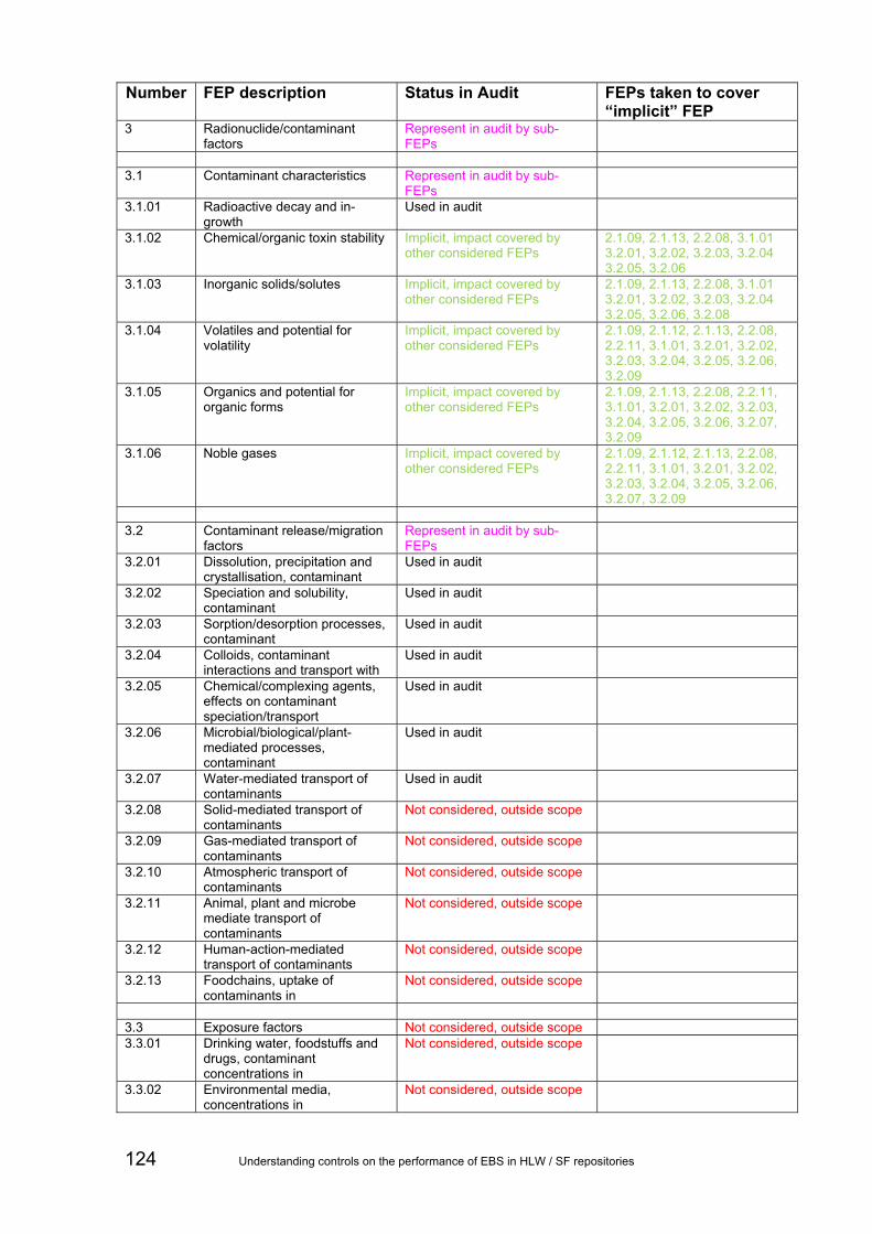
Number FEP description Status in Audit FEPs taken to cover “implicit” FEP
3 Radionuclide/contaminant factors
Represent in audit by sub-FEPs
3.1 Contaminant characteristics Represent in audit by sub-
FEPs
3.1.01 Radioactive decay and in-growth
Used in audit
3.1.02 Chemical/organic toxin stability Implicit, impact covered by other considered FEPs
2.1.09, 2.1.13, 2.2.08, 3.1.01 3.2.01, 3.2.02, 3.2.03, 3.2.04 3.2.05, 3.2.06
3.1.03 Inorganic solids/solutes Implicit, impact covered by other considered FEPs
2.1.09, 2.1.13, 2.2.08, 3.1.01 3.2.01, 3.2.02, 3.2.03, 3.2.04 3.2.05, 3.2.06, 3.2.08
3.1.04 Volatiles and potential for volatility
Implicit, impact covered by other considered FEPs
2.1.09, 2.1.12, 2.1.13, 2.2.08, 2.2.11, 3.1.01, 3.2.01, 3.2.02, 3.2.03, 3.2.04, 3.2.05, 3.2.06, 3.2.09
3.1.05 Organics and potential for organic forms
Implicit, impact covered by other considered FEPs
2.1.09, 2.1.13, 2.2.08, 2.2.11, 3.1.01, 3.2.01, 3.2.02, 3.2.03, 3.2.04, 3.2.05, 3.2.06, 3.2.07, 3.2.09
3.1.06 Noble gases Implicit, impact covered by other considered FEPs
2.1.09, 2.1.12, 2.1.13, 2.2.08, 2.2.11, 3.1.01, 3.2.01, 3.2.02, 3.2.03, 3.2.04, 3.2.05, 3.2.06, 3.2.07, 3.2.09
3.2 Contaminant release/migration
factors Represent in audit by sub-FEPs
3.2.01 Dissolution, precipitation and crystallisation, contaminant
Used in audit
3.2.02 Speciation and solubility, contaminant
Used in audit
3.2.03 Sorption/desorption processes, contaminant
Used in audit
3.2.04 Colloids, contaminant interactions and transport with
Used in audit
3.2.05 Chemical/complexing agents, effects on contaminant speciation/transport
Used in audit
3.2.06 Microbial/biological/plant-mediated processes, contaminant
Used in audit
3.2.07 Water-mediated transport of contaminants
Used in audit
3.2.08 Solid-mediated transport of contaminants
Not considered, outside scope
3.2.09 Gas-mediated transport of contaminants
Not considered, outside scope
3.2.10 Atmospheric transport of contaminants
Not considered, outside scope
3.2.11 Animal, plant and microbe mediate transport of contaminants
Not considered, outside scope
3.2.12 Human-action-mediated transport of contaminants
Not considered, outside scope
3.2.13 Foodchains, uptake of contaminants in
Not considered, outside scope
3.3 Exposure factors Not considered, outside scope 3.3.01 Drinking water, foodstuffs and
drugs, contaminant concentrations in
Not considered, outside scope
3.3.02 Environmental media, concentrations in
Not considered, outside scope
124 Understanding controls on the performance of EBS in HLW / SF repositories

Number FEP description Status in Audit FEPs taken to cover “implicit” FEP
3.3.03 Non-food products, concentrations in
Not considered, outside scope
3.3.04 Exposure modes Not considered, outside scope 3.3.05 Dosimetry Not considered, outside scope 3.3.06 Radiological toxicity/effects Not considered, outside scope 3.3.07 Non-radiological toxicity/effects Not considered, outside scope 3.3.08 Radon and radon-daughter
exposure Not considered, outside scope
1“Implicit, not considered directly” means this FEP is considered as a matter of course when evaluating the factors that control repository performance. Thus, during the audit there is no need to check whether the safety functions and FEP groups identified in Section 3 cover these “implicit” FEPs. 2“Not considered, outside scope” means the FEP is outside the scope of the project; it is inappropriate to check whether the safety functions and FEP groups identified in Section 3 cover these “implicit” FEPs.
3“Implicit, impact covered by other considered FEPs” means that the effects of the FEP can be represented by other FEPs and therefore it is not included in the set of FEPs used to audit safety functions and FEP groups identified in Section 3. Judgment as to whether a FEP is “Implicit” is made bearing in mind the aims of this project. For example, for the purposes of this project, the influence on repository performance of FEP 1.1.06 “Waste allocation” can be covered by the effects of FEPs 1.1.07 “Repository design”, 2.1.01 ”Inventory, radionuclide and other material” and 2.1.02 “Waste form materials and characteristics”.
4The NEA’s FEP list does not include alteration of igneous rocks at temperatures/pressures comparable to those under which diagenesis of sedimentary rocks occurs. There is much literature on this “low-grade metamorphism” (see Frey and Robinson, 1998). Instead, the NEA’s list defines “metamorphism” to be “The processes by which rocks are changed by the action of heat (>200 °C) and pressure at great depths (usually several kilometres) beneath the Earth’s surface or in the vicinity of magmatic activity.” It also defines “diagenesis” to be “The processes by which deposited sediments at or near the Earth’s surface are formed into rocks by compaction, cementation and crystallisation, i.e. under conditions of temperature and pressure normal to the upper few kilometres of the Earth’s crust”. Thus, on the basis of these definitions, “metamorphism” would be excluded from the audit (since it applies to temperatures above 200 °C, which would not occur in any repository environment) while alteration of igneous rocks at lower temperatures would not be included (because diagenesis affects only sediments/sedimentary rocks). As a result, FEP 1.2.05 is in fact relevant to the project, although its significant safety-relevant effects can be taken into account by suitably treating other FEPs in the analysis.
The above screening process produced the list of FEPs in Table B.2. These FEPs were then used to audit the FEPs and groups of FEPs in Section 4.2 of the report.
Table B.2 FEPs from the NEA’s FEP list (NEA, 2000) used in the audit and their potential impacts on safety functions.
Number FEP description Potential impact(s) on safety functions
1.1.03 Emplacement of wastes and backfilling Positive (if undertaken
appropriately) 1.1.04 Closure and repository sealing Positive (if undertaken
appropriately) 1.1.07 Repository design Positive (if undertaken
appropriately) 1.1.08 Quality control Positive (if undertaken
appropriately) 1.1.09 Schedule and planning Positive (if undertaken
appropriately) 1.2.02 Deformation, elastic, plastic or brittle Positive and/or negative 1.2.03 Seismicity Usually no effect, any effect
likely to be negative but may be positive
Understanding controls on the performance of EBS in HLW / SF repositories 125

Number FEP description Potential impact(s) on safety functions
1.2.05 Metamorphism3 Positive and/or negative
1.2.08 Diagenesis Positive and/or negative 1.2.09 Salt diapirism and dissolution Negative 1.2.10 Hydrological/hydrogeological response to
geological changes Positive and/or negative
1.3.07 Hydrological/hydrogeological response to climate changes
Positive and/or negative
2.1.01 Inventory, radionuclide and other material Positive and/or negative 2.1.02 Waste form materials and characteristics Positive (if selected
appropriately) 2.1.03 Container materials and characteristics Positive (if selected
appropriately) 2.1.04 Buffer/backfill materials and characteristics Positive (if selected
appropriately) 2.1.05 Seals cavern/tunnel/shaft Positive (if materials selected
appropriately) 2.1.06 Other engineered materials features and
characteristics Positive (if materials selected appropriately)
2.1.07 Mechanical processes and conditions (in wastes and EBS)
Positive and/or negative
2.1.08 Hydraulic/hydrogeological processes and conditions (in wastes and EBS)
Positive and/or negative
2.1.09 Chemical/geochemical processes and conditions (in wastes and EBS)
Positive and/or negative
2.1.11 Thermal processes and conditions (in wastes and EBS)
Positive and/or negative
2.1.12 Gas sources and effects (in wastes and EBS) Most likely negative, some positive
2.1.13 Radiation effects (in wastes and EBS) Most likely negative 2.2.01 Excavation disturbed zone/host rock Most likely negative, some
positive 2.2.02 Host rock Positive (if selected
appropriately) 2.2.04 Discontinuities, large scale (other) Positive and/or negative 2.2.05 Contaminant transport path characteristics (in
geosphere) Positive and/or negative
2.2.06 Mechanical processes and conditions (in geosphere)
Positive and/or negative
2.2.07 Hydraulic/hydrogeological processes and conditions (in geosphere)
Positive and/or negative
2.2.08 Chemical/geochemical processes and conditions (in geosphere)
Positive and/or negative
2.2.10 Thermal processes and conditions (in geosphere) Positive and/or negative 2.2.11 Gas sources and effects (in geosphere) Most likely negative, some
positive 3.1.01 Radioactive decay and in-growth Positive and/or negative 3.2.01 Dissolution, precipitation and crystallisation,
contaminant Positive and/or negative
3.2.02 Speciation and solubility, contaminant Positive and/or negative 3.2.03 Sorption/desorption processes, contaminant Positive and/or negative 3.2.04 Colloids, contaminant interactions and transport
with Positive and/or negative
3.2.05 Chemical/complexing agents, effects on contaminant speciation/transport
Positive and/or negative
3.2.06 Microbial/biological/plant-mediated processes, contaminant
Positive and/or negative
3.2.07 Water-mediated transport of contaminants Negative
126 Understanding controls on the performance of EBS in HLW / SF repositories

Comparisons between the FEPs and groups of FEPs identified in Section 5.2 and the FEPs from the screened NEA’s FEP list in Table B.2, are given in are given in B.3 to B.6.
Understanding controls on the performance of EBS in HLW / SF repositories 127

Appendix B References FREY, M. AND ROBINSON, D. 1998. Low-grade metamorphism. Blackwell Scientific Publishing, Oxford, 328pp.
NUCLEAR ENERGY AGENCY (NEA), 2000. Features, events and processes (FEPs) for geologic disposal of radioactive waste: an international database. Organisation for Economic Cooperation and Development (OECD). Paris. ISBN: 9789264024397. 89pp.
Understanding controls on the performance of EBS in HLW / SF repositories
128

Understanding controls on the performance of EBS in HLW / SF repositories 129
Table B.3 Comparison between the FEPs and FEP groups for the “longer-lived waste package/overpack + clay buffer + hard fractured rock” (Table 5.2) and the NEA’s FEPs in Table B2.
C = Correspond, denoting that the NEA FEP corresponds completely or in part to the safety function or FEP group.
Nuclear Energy Agency FEP’s
FEP’s or FEP group
1.1.03 Emplacement of wastes and backfilling
1.1.04 Closure and repository sealing
1.1.07 Repository design
1.1.08 Quality control
1.1.09 Schedule and planning
1.2.02 Deformation, elastic, plastic or brittle
‘Aggressive’ chemical conditions caused by wasteform Backfill C C C C Backfill keeps buffer in place C C Backfill may swell and press against seals C C Backfill provides low permeability C C Canister C C Canister contains wasteform Canister corrodes giving reducing conditions Canister prevents release until failure Clay buffer C C Clay buffer conditions the chemistry of waters that may reach the wasteform after canister failure C Clay buffer conducts heat C Clay buffer filters colloids C Clay buffer may swell and press against backfill C Clay buffer prevents microbial activity C Clay buffer protects canister C Clay buffer provides a diffusive environment C Clay buffer undergoes erosion and loss of swelling pressure Corrosion of canister Emplacement of the backfill at required rate and density C C C Emplacement of the backfill to required density C C C Erosion/colloid formation/advection within clay buffer Fracture flow in host rock Glacial waters Hard fractured host rock C Host rock conducts heat

Understanding controls on the performance of EBS in HLW / SF repositories 130
Nuclear Energy Agency FEP’s
FEP’s or FEP group
1.1.03 Emplacement of wastes and backfilling
1.1.04 Closure and repository sealing
1.1.07 Repository design
1.1.08 Quality control
1.1.09 Schedule and planning
1.2.02 Deformation, elastic, plastic or brittle
Host rock provides suitable groundwater flow and chemistry for buffer Host rock provides suitable groundwater flow and chemistry, and retardation for some radionuclides. Host rock provides suitable groundwater flow field for backfill Host rock provides suitable stress and groundwater flow fields for seals Host rock provides suitable stress, groundwater flows and chemistry for canister Initial defects in canister C Mechanical failure of canister Piping / erosion and degradation of the backfill Possibly iron-bentonite interactions if a ferrous metal canister used Possibly loss of clay colloids from the clay buffer into the host rock Possibly minor alteration of the host rock caused by the seal (e.g. by cement sealing materials) Possibly minor reaction of the backfill with the host rock Possibly minor reaction of the clay buffer with the host rock Radiation effects from waste form on canister Radionuclide release from wasteform Seal anchoring strength and degradation C C Seal properties and degradation C Seal provides low permeability C Seals C C C Seals prevent access C Seals provide mechanical support for backfill C Seismic activity and shearing Slow dissolution of waste form and release of radionuclides Unexpected ‘poor ground conditions’ C Wasteform C C Does the NEA FEP correspond to at least one safety function / FEP group? Yes Yes Yes Yes No Yes
Table B.3 continued: “longer-lived waste package/overpack + clay buffer + hard fractured rock” C = Correspond, denoting that the NEA FEP corresponds completely or in part to the safety function or FEP group.

Understanding controls on the performance of EBS in HLW / SF repositories 131
Table B.3 continued: “longer-lived waste package/overpack + clay buffer + hard fractured rock” C = Correspond, denoting that the NEA FEP corresponds completely or in part to the safety function or FEP group.
Nuclear Energy Agency FEP’s
FEP’s or FEP group
1.2.03 Seismicity
1.2.09 Salt diapirism and dissolution
1.2.10 Hydrological / hydrogeological response to geological changes
1.3.07 Hydrological / hydrogeological response to climate changes
2.1.01 Inventory, radionuclide and other material
‘Aggressive’ chemical conditions caused by wasteform Backfill Backfill keeps buffer in place Backfill may swell and press against seals Backfill provides low permeability Canister Canister contains wasteform Canister corrodes giving reducing conditions Canister prevents release until failure Clay buffer Clay buffer conditions the chemistry of waters that may reach the wasteform after canister failure Clay buffer conducts heat Clay buffer filters colloids Clay buffer may swell and press against backfill Clay buffer prevents microbial activity Clay buffer protects canister Clay buffer provides a diffusive environment Clay buffer undergoes erosion and loss of swelling pressure Corrosion of canister Emplacement of the backfill at required rate and density Emplacement of the backfill to required density Erosion/colloid formation/advection within clay buffer Fracture flow in host rock C C Glacial waters C Hard fractured host rock Host rock conducts heat

Understanding controls on the performance of EBS in HLW / SF repositories 132
Nuclear Energy Agency FEP’sFEP’s or FEP group
1.2.03 Seismicity
1.2.09 Salt diapirism and dissolution
1.2.10 Hydrological / hydrogeological response to geological changes
1.3.07 Hydrological / hydrogeological response to climate changes
2.1.01 Inventory, radionuclide and other material
Host rock provides suitable groundwater flow and chemistry for buffer C C Host rock provides suitable groundwater flow and chemistry, and retardation for some radionuclides. C C Host rock provides suitable groundwater flow field for backfill C C Host rock provides suitable stress and groundwater flow fields for seals C C Host rock provides suitable stress, groundwater flows and chemistry for canister C C Initial defects in canister Mechanical failure of canister Piping / erosion and degradation of the backfill Possibly iron-bentonite interactions if a ferrous metal canister used Possibly loss of clay colloids from the clay buffer into the host rock Possibly minor alteration of the host rock caused by the seal (e.g. by cement sealing materials) Possibly minor reaction of the backfill with the host rock Possibly minor reaction of the clay buffer with the host rock Radiation effects from waste form on canister Radionuclide release from wasteform C Seal anchoring strength and degradation Seal properties and degradation Seal provides low permeability Seals Seals prevent access Seals provide mechanical support for backfill Seismic activity and shearing C Slow dissolution of waste form and release of radionuclides Unexpected ‘poor ground conditions’ Wasteform C Does the NEA FEP correspond to at least one safety function / FEP group? Yes No Yes Yes Yes
Table B.3 continued: “longer-lived waste package/overpack + clay buffer + hard fractured rock” C = Correspond, denoting that the NEA FEP corresponds completely or in part to the safety function or FEP group.

Understanding controls on the performance of EBS in HLW / SF repositories 133
Table B.3 continued: “longer-lived waste package/overpack + clay buffer + hard fractured rock” C = Correspond, denoting that the NEA FEP corresponds completely or in part to the safety function or FEP group.
Nuclear Energy Agency FEP’s
FEP’s or FEP group
2.1.02 Waste form materials and characteristics
2.1.03 Container materials and characteristics
2.1.04 Buffer / backfill materials and characteristics
2.1.05 Seals cavern/ tunnel/ shaft
2.1.06 Other engineered materials features and characteristics
‘Aggressive’ chemical conditions caused by wasteform Backfill C Backfill keeps buffer in place C Backfill may swell and press against seals C Backfill provides low permeability C Canister C Canister contains wasteform C C Canister corrodes giving reducing conditions C Canister prevents release until failure C Clay buffer C Clay buffer conditions the chemistry of waters that may reach the wasteform after canister failure C Clay buffer conducts heat C Clay buffer filters colloids C Clay buffer may swell and press against backfill C Clay buffer prevents microbial activity C Clay buffer protects canister C Clay buffer provides a diffusive environment C Clay buffer undergoes erosion and loss of swelling pressure C Corrosion of canister C Emplacement of the backfill at required rate and density C Emplacement of the backfill to required density C Erosion/colloid formation/advection within clay buffer C Fracture flow in host rock Glacial waters Hard fractured host rock Host rock conducts heat

Understanding controls on the performance of EBS in HLW / SF repositories 134
Nuclear Energy Agency FEP’s
FEP’s or FEP group
2.1.02 Waste form materials and characteristics
2.1.03 Container materials and characteristics
2.1.04 Buffer / backfill materials and characteristics
2.1.05 Seals cavern/ tunnel/ shaft
2.1.06 Other engineered materials features and characteristics
Host rock provides suitable groundwater flow and chemistry for buffer Host rock provides suitable groundwater flow and chemistry, and retardation for some radionuclides. Host rock provides suitable groundwater flow field for backfill Host rock provides suitable stress and groundwater flow fields for seals Host rock provides suitable stress, groundwater flows and chemistry for canister Initial defects in canister C Mechanical failure of canister C Piping / erosion and degradation of the backfill C Possibly iron-bentonite interactions if a ferrous metal canister used C C Possibly loss of clay colloids from the clay buffer into the host rock Possibly minor alteration of the host rock caused by the seal (e.g. by cement sealing materials) Possibly minor reaction of the backfill with the host rock C Possibly minor reaction of the clay buffer with the host rock C Radiation effects from waste form on canister C C Radionuclide release from wasteform C Seal anchoring strength and degradation C Seal properties and degradation C Seal provides low permeability C Seals C Seals prevent access C Seals provide mechanical support for backfill C Seismic activity and shearing Slow dissolution of waste form and release of radionuclides C Unexpected ‘poor ground conditions’ Wasteform C Does the NEA FEP correspond to at least one safety function / FEP group? Yes Yes Yes Yes No
Table B.3 continued: “longer-lived waste package/overpack + clay buffer + hard fractured rock” C = Correspond, denoting that the NEA FEP corresponds completely or in part to the safety function or FEP group.

Understanding controls on the performance of EBS in HLW / SF repositories 135
Table B.3 continued: “longer-lived waste package/overpack + clay buffer + hard fractured rock” C = Correspond, denoting that the NEA FEP corresponds completely or in part to the safety function or FEP group.
Nuclear Energy Agency FEP’s
FEP’s or FEP group
2.1.07 Mechanical processes and conditions (in wastes and EBS)
2.1.08 Hydraulic / hydrogeological processes and conditions (in wastes and EBS)
2.1.09 Chemical / geochemical processes and conditions (in wastes and EBS)
2.1.11 Thermal processes and conditions (in wastes and EBS)
‘Aggressive’ chemical conditions caused by wasteform C Backfill Backfill keeps buffer in place C Backfill may swell and press against seals C Backfill provides low permeability C Canister Canister contains wasteform Canister corrodes giving reducing conditions C Canister prevents release until failure C C C Clay buffer Clay buffer conditions the chemistry of waters that may reach the wasteform after canister failure C Clay buffer conducts heat C Clay buffer filters colloids C Clay buffer may swell and press against backfill C Clay buffer prevents microbial activity C C Clay buffer protects canister Clay buffer provides a diffusive environment C Clay buffer undergoes erosion and loss of swelling pressure C Corrosion of canister C Emplacement of the backfill at required rate and density Emplacement of the backfill to required density Erosion/colloid formation/advection within clay buffer C Fracture flow in host rock Glacial waters C Hard fractured host rock Host rock conducts heat

Understanding controls on the performance of EBS in HLW / SF repositories 136
Nuclear Energy Agency FEP’s
FEP’s or FEP group
2.1.07 Mechanical processes and conditions (in wastes and EBS)
2.1.08 Hydraulic / hydrogeological processes and conditions (in wastes and EBS)
2.1.09 Chemical / geochemical processes and conditions (in wastes and EBS)
2.1.11 Thermal processes and conditions (in wastes and EBS)
Host rock provides suitable groundwater flow and chemistry for buffer C Host rock provides suitable groundwater flow and chemistry, and retardation for some radionuclides. Host rock provides suitable groundwater flow field for backfill Host rock provides suitable stress and groundwater flow fields for seals C Host rock provides suitable stress, groundwater flows and chemistry for canister C Initial defects in canister C Mechanical failure of canister C Piping / erosion and degradation of the backfill C Possibly iron-bentonite interactions if a ferrous metal canister used C Possibly loss of clay colloids from the clay buffer into the host rock C C Possibly minor alteration of the host rock caused by the seal (e.g. by cement sealing materials) C Possibly minor reaction of the backfill with the host rock C Possibly minor reaction of the clay buffer with the host rock C Radiation effects from waste form on canister Radionuclide release from wasteform C Seal anchoring strength and degradation C C C Seal properties and degradation C C C Seal provides low permeability C Seals Seals prevent access Seals provide mechanical support for backfill C Seismic activity and shearing C Slow dissolution of waste form and release of radionuclides C C Unexpected ‘poor ground conditions’ Wasteform Does the NEA FEP correspond to at least one safety function / FEP group? Yes Yes Yes Yes
Table B.3 continued: “longer-lived waste package/overpack + clay buffer + hard fractured rock” C = Correspond, denoting that the NEA FEP corresponds completely or in part to the safety function or FEP group.

Understanding controls on the performance of EBS in HLW / SF repositories 137
Table B.3 continued: “longer-lived waste package/overpack + clay buffer + hard fractured rock” C = Correspond, denoting that the NEA FEP corresponds completely or in part to the safety function or FEP group.
Nuclear Energy Agency FEP’s
FEP’s or FEP group
2.1.12 Gas sources and effects (in wastes and EBS)
2.1.13 Radiation effects (in wastes and EBS)
2.2.01 Excavation disturbed zone / host rock
2.2.02 Host rock
2.2.04 Discontinuities, large scale (other)
2.2.05 Contaminant transport path characteristics (in geosphere)
‘Aggressive’ chemical conditions caused by wasteform Backfill Backfill keeps buffer in place Backfill may swell and press against seals Backfill provides low permeability Canister C Canister contains wasteform Canister corrodes giving reducing conditions C Canister prevents release until failure Clay buffer Clay buffer conditions the chemistry of waters that may reach the wasteform after canister failure Clay buffer conducts heat Clay buffer filters colloids Clay buffer may swell and press against backfill Clay buffer prevents microbial activity Clay buffer protects canister Clay buffer provides a diffusive environment Clay buffer undergoes erosion and loss of swelling pressure Corrosion of canister C Emplacement of the backfill at required rate and density Emplacement of the backfill to required density Erosion/colloid formation/advection within clay buffer Fracture flow in host rock C C Glacial waters Hard fractured host rock C Host rock conducts heat

Understanding controls on the performance of EBS in HLW / SF repositories 138
Nuclear Energy Agency FEP’s
FEP’s or FEP group
2.1.12 Gas sources and effects (in wastes and EBS)
2.1.13 Radiation effects (in wastes and EBS)
2.2.01 Excavation disturbed zone / host rock
2.2.02 Host rock
2.2.04 Discontinuities, large scale (other)
2.2.05 Contaminant transport path characteristics (in geosphere)
Host rock provides suitable groundwater flow and chemistry for buffer C C C Host rock provides suitable groundwater flow and chemistry, and retardation for some radionuclides. C C Host rock provides suitable groundwater flow field for backfill C C C Host rock provides suitable stress and groundwater flow fields for seals C C C Host rock provides suitable stress, groundwater flows and chemistry for canister C C C Initial defects in canister Mechanical failure of canister Piping / erosion and degradation of the backfill Possibly iron-bentonite interactions if a ferrous metal canister used Possibly loss of clay colloids from the clay buffer into the host rock Possibly minor alteration of the host rock caused by the seal (e.g. by cement sealing materials) Possibly minor reaction of the backfill with the host rock Possibly minor reaction of the clay buffer with the host rock Radiation effects from waste form on canister C Radionuclide release from wasteform Seal anchoring strength and degradation Seal properties and degradation Seal provides low permeability Seals Seals prevent access Seals provide mechanical support for backfill Seismic activity and shearing Slow dissolution of waste form and release of radionuclides Unexpected ‘poor ground conditions’ C Wasteform Does the NEA FEP correspond to at least one safety function / FEP group? Yes Yes Yes Yes Yes Yes
Table B.3 continued: “longer-lived waste package/overpack + clay buffer + hard fractured rock” C = Correspond, denoting that the NEA FEP corresponds completely or in part to the safety function or FEP group.

Understanding controls on the performance of EBS in HLW / SF repositories 139
Table B.3 continued: “longer-lived waste package/overpack + clay buffer + hard fractured rock” C = Correspond, denoting that the NEA FEP corresponds completely or in part to the safety function or FEP group.
Nuclear Energy Agency FEP’s
FEP’s or FEP group
2.2.06 Mechanical processes and conditions (in geosphere)
2.2.07 Hydraulic / hydrogeological processes and conditions (in geosphere)
2.2.08 Chemical / geochemical processes and conditions (in geosphere)
2.2.10 Thermal processes and conditions (in geosphere)
2.2.11 Gas sources and effects (in geosphere)
‘Aggressive’ chemical conditions caused by wasteform Backfill Backfill keeps buffer in place Backfill may swell and press against seals Backfill provides low permeability Canister Canister contains wasteform Canister corrodes giving reducing conditions Canister prevents release until failure Clay buffer Clay buffer conditions the chemistry of waters that may reach the wasteform after canister failure Clay buffer conducts heat Clay buffer filters colloids Clay buffer may swell and press against backfill Clay buffer prevents microbial activity Clay buffer protects canister Clay buffer provides a diffusive environment Clay buffer undergoes erosion and loss of swelling pressure Corrosion of canister Emplacement of the backfill at required rate and density Emplacement of the backfill to required density Erosion/colloid formation/advection within clay buffer Fracture flow in host rock C Glacial waters C Hard fractured host rock Host rock conducts heat C

Understanding controls on the performance of EBS in HLW / SF repositories 140
Nuclear Energy Agency FEP’s
FEP’s or FEP group
2.2.06 Mechanical processes and conditions (in geosphere)
2.2.07 Hydraulic / hydrogeological processes and conditions (in geosphere)
2.2.08 Chemical / geochemical processes and conditions (in geosphere)
2.2.10 Thermal processes and conditions (in geosphere)
2.2.11 Gas sources and effects (in geosphere)
Host rock provides suitable groundwater flow and chemistry for buffer C C Host rock provides suitable groundwater flow and chemistry, and retardation for some radionuclides. C C C C Host rock provides suitable groundwater flow field for backfill C Host rock provides suitable stress and groundwater flow fields for seals C C Host rock provides suitable stress, groundwater flows and chemistry for canister C C C Initial defects in canister Mechanical failure of canister C Piping / erosion and degradation of the backfill Possibly iron-bentonite interactions if a ferrous metal canister used Possibly loss of clay colloids from the clay buffer into the host rock Possibly minor alteration of the host rock caused by the seal (e.g. by cement sealing materials) C Possibly minor reaction of the backfill with the host rock C Possibly minor reaction of the clay buffer with the host rock C Radiation effects from waste form on canister Radionuclide release from wasteform Seal anchoring strength and degradation Seal properties and degradation Seal provides low permeability Seals Seals prevent access Seals provide mechanical support for backfill Seismic activity and shearing C Slow dissolution of waste form and release of radionuclides Unexpected ‘poor ground conditions’ C Wasteform Does the NEA FEP correspond to at least one safety function / FEP group? Yes Yes Yes Yes Yes
Table B.3 continued: “longer-lived waste package/overpack + clay buffer + hard fractured rock” C = Correspond, denoting that the NEA FEP corresponds completely or in part to the safety function or FEP group.

Understanding controls on the performance of EBS in HLW / SF repositories 141
Table B.3 continued: “longer-lived waste package/overpack + clay buffer + hard fractured rock” C = Correspond, denoting that the NEA FEP corresponds completely or in part to the safety function or FEP group.
Nuclear Energy Agency FEP’s
FEP’s or FEP group
3.1.01 Radioactive decay and in-growth
3.2.01 Dissolution, precipitation and crystallisation, contaminant
3.2.02 Speciation and solubility, contaminant
3.2.03 Sorption / desorption processes, contaminant
3.2.04 Colloids, contaminant interactions and transport with
‘Aggressive’ chemical conditions caused by wasteform C C C Backfill Backfill keeps buffer in place Backfill may swell and press against seals Backfill provides low permeability Canister Canister contains wasteform Canister corrodes giving reducing conditions Canister prevents release until failure Clay buffer Clay buffer conditions the chemistry of waters that may reach the wasteform after canister failure Clay buffer conducts heat Clay buffer filters colloids Clay buffer may swell and press against backfill Clay buffer prevents microbial activity Clay buffer protects canister Clay buffer provides a diffusive environment Clay buffer undergoes erosion and loss of swelling pressure Corrosion of canister Emplacement of the backfill at required rate and density Emplacement of the backfill to required density Erosion/colloid formation/advection within clay buffer Fracture flow in host rock Glacial waters Hard fractured host rock Host rock conducts heat

Understanding controls on the performance of EBS in HLW / SF repositories 142
Nuclear Energy Agency FEP’s
FEP’s or FEP group
3.1.01 Radioactive decay and in-growth
3.2.01 Dissolution, precipitation and crystallisation, contaminant
3.2.02 Speciation and solubility, contaminant
3.2.03 Sorption / desorption processes, contaminant
3.2.04 Colloids, contaminant interactions and transport with
Host rock provides suitable groundwater flow and chemistry for buffer Host rock provides suitable groundwater flow and chemistry, and retardation for some radionuclides. C C Host rock provides suitable groundwater flow field for backfill Host rock provides suitable stress and groundwater flow fields for seals Host rock provides suitable stress, groundwater flows and chemistry for canister Initial defects in canister Mechanical failure of canister Piping / erosion and degradation of the backfill Possibly iron-bentonite interactions if a ferrous metal canister used Possibly loss of clay colloids from the clay buffer into the host rock C Possibly minor alteration of the host rock caused by the seal (e.g. by cement sealing materials) Possibly minor reaction of the backfill with the host rock Possibly minor reaction of the clay buffer with the host rock Radiation effects from waste form on canister C Radionuclide release from wasteform C C C C Seal anchoring strength and degradation Seal properties and degradation Seal provides low permeability Seals Seals prevent access Seals provide mechanical support for backfill Seismic activity and shearing Slow dissolution of waste form and release of radionuclides C C C C Unexpected ‘poor ground conditions’ Wasteform Does the NEA FEP correspond to at least one safety function / FEP group? Yes Yes Yes Yes Yes
Table B.3 continued: “longer-lived waste package/overpack + clay buffer + hard fractured rock” C = Correspond, denoting that the NEA FEP corresponds completely or in part to the safety function or FEP group.

Understanding controls on the performance of EBS in HLW / SF repositories 143
Table B.3 continued: “longer-lived waste package/overpack + clay buffer + hard fractured rock” C = Correspond, denoting that the NEA FEP corresponds completely or in part to the safety function or FEP group.
Nuclear Energy Agency FEP’s
FEP’s or FEP group
3.2.05 Chemical / complexing agents, effects on contaminant speciation / transport
3.2.06 Microbial / biological / plant-mediated processes, contaminant
3.2.07 Water-mediated transport of contaminants
Does the safety function or FEP group correspond to at least one NEA FEP?
‘Aggressive’ chemical conditions caused by wasteform Yes Backfill Yes Backfill keeps buffer in place Yes Backfill may swell and press against seals Yes Backfill provides low permeability Yes Canister Yes Canister contains wasteform Yes Canister corrodes giving reducing conditions Yes Canister prevents release until failure Yes Clay buffer Yes Clay buffer conditions the chemistry of waters that may reach the wasteform after canister failure Yes Clay buffer conducts heat Yes Clay buffer filters colloids Yes Clay buffer may swell and press against backfill Yes Clay buffer prevents microbial activity C Yes Clay buffer protects canister Yes Clay buffer provides a diffusive environment Yes Clay buffer undergoes erosion and loss of swelling pressure Yes Corrosion of canister Yes Emplacement of the backfill at required rate and density Yes Emplacement of the backfill to required density Yes Erosion/colloid formation/advection within clay buffer Yes Fracture flow in host rock Yes Glacial waters Yes Hard fractured host rock Yes Host rock conducts heat Yes

Understanding controls on the performance of EBS in HLW / SF repositories 144
Nuclear Energy Agency FEP’s
FEP’s or FEP group
3.2.05 Chemical / complexing agents, effects on contaminant speciation / transport
3.2.06 Microbial / biological / plant-mediated processes, contaminant
3.2.07 Water-mediated transport of contaminants
Does the safety function or FEP group correspond to at least one NEA FEP?
Host rock provides suitable groundwater flow and chemistry for buffer Yes Host rock provides suitable groundwater flow and chemistry, and retardation for some radionuclides. C Yes Host rock provides suitable groundwater flow field for backfill Yes Host rock provides suitable stress and groundwater flow fields for seals Yes Host rock provides suitable stress, groundwater flows and chemistry for canister Yes Initial defects in canister Yes Mechanical failure of canister Yes Piping / erosion and degradation of the backfill Yes Possibly iron-bentonite interactions if a ferrous metal canister used Yes Possibly loss of clay colloids from the clay buffer into the host rock Yes Possibly minor alteration of the host rock caused by the seal (e.g. by cement sealing materials) Yes Possibly minor reaction of the backfill with the host rock Yes Possibly minor reaction of the clay buffer with the host rock Yes Radiation effects from waste form on canister Yes Radionuclide release from wasteform C C Yes Seal anchoring strength and degradation Yes Seal properties and degradation Yes Seal provides low permeability Yes Seals Yes Seals prevent access Yes Seals provide mechanical support for backfill Yes Seismic activity and shearing Yes Slow dissolution of waste form and release of radionuclides C C Yes Unexpected ‘poor ground conditions’ Yes Wasteform Yes Does the NEA FEP correspond to at least one safety function / FEP group? Yes Yes Yes
Table B.3 continued: “longer-lived waste package/overpack + clay buffer + hard fractured rock” C = Correspond, denoting that the NEA FEP corresponds completely or in part to the safety function or FEP group.

Understanding controls on the performance of EBS in HLW / SF repositories 145
Table B.4 Comparison between the FEPs and FEP groups for the “mudrock host rock and a clay buffer” (Table 5.3) and the NEA’s
FEPs in Table B.2. C = Correspond, denoting that the NEA FEP corresponds completely or in part to the safety function or FEP group.
Nuclear Energy Agency FEP’s
FEP’s or FEP group
1.1.03 Emplacement of wastes and backfilling
1.1.04 Closure and repository sealing
1.1.07 Repository design
1.1.08 Quality control
1.1.09 Schedule and planning
1.2.02 Deformation, elastic, plastic or brittle
‘Aggressive’ chemical conditions caused by wasteform Backfill C C C C Backfill keeps buffer in place C C Backfill may swell and press against seals C C Backfill provides low permeability and retardation for some radionuclides C C Buffer may be affected by H2 gas from corrosion if a ferrous metal canister used Canister C C Canister contains wasteform Canister corrodes giving reducing conditions Canister prevents release until failure Clay buffer C C C Clay buffer conditions the chemistry of waters that may reach the wasteform after canister failure C Clay buffer conducts heat C Clay buffer filters colloids C Clay buffer may swell and press against backfill C Clay buffer prevents microbial activity C Clay buffer protects canister C Clay buffer provides a diffusive environment and retardation for some radionuclides C Clay buffer undergoes loss of swelling pressure Corrosion of canister Degradation of backfill C C Emplacement of the backfill at required rate and density C C C Emplacement of the backfull to required density C C C Glacial waters

Understanding controls on the performance of EBS in HLW / SF repositories 146
Nuclear Energy Agency FEP’s
FEP’s or FEP group
1.1.03 Emplacement of wastes and backfilling
1.1.04 Closure and repository sealing
1.1.07 Repository design
1.1.08 Quality control
1.1.09 Schedule and planning
1.2.02 Deformation, elastic, plastic or brittle
Host rock conducts heat Host rock provides suitable groundwater flow and chemistry for buffer Host rock provides suitable groundwater flow and chemistry, and retardation for some radionuclides. Host rock provides suitable groundwater flow field for backfill Host rock provides suitable stress and groundwater flow fields for seals Host rock provides suitable stress, groundwater flows and chemistry for canister Indurated mudstone host rock C Initial defects in canister C Mechanical failure of canister Possibly iron-bentonite interactions if a ferrous metal canister used Possibly minor alteration of the host rock caused by the seal (e.g. by cement sealing materials) Possibly minor reaction of the backfill with the host rock Radiation effects from waste form on canister Radionuclide release from wasteform Seal anchoring strength and degradation C C Seal properties and degradation C Seal provides low permeability C Seals C C C Seals prevent access C Seals provide mechanical support for backfill C Seismic activity and shearing Slow dissolution of waste form and release of radionuclides Unexpected ‘poor ground conditions’ C Wasteform C C Does the NEA FEP correspond to at least one safety function / FEP group? Yes Yes Yes Yes No Yes

Understanding controls on the performance of EBS in HLW / SF repositories 147
Table B.4 continued: “mudrock host rock and a clay buffer” C = Correspond, denoting that the NEA FEP corresponds completely or in part to the safety function or FEP group.
Nuclear Energy Agency FEP’s
FEP’s or FEP group
1.2.03 Seismicity
1.2.09 Salt diapirism and dissolution
1.2.10 Hydrological / hydrogeological response to geological changes
1.3.07 Hydrological / hydrogeological response to climate changes
2.1.01 Inventory, radionuclide and other material
‘Aggressive’ chemical conditions caused by wasteform Backfill Backfill keeps buffer in place Backfill may swell and press against seals Backfill provides low permeability and retardation for some radionuclides Buffer may be affected by H2 gas from corrosion if a ferrous metal canister used Canister Canister contains wasteform Canister corrodes giving reducing conditions Canister prevents release until failure Clay buffer Clay buffer conditions the chemistry of waters that may reach the wasteform after canister failure Clay buffer conducts heat Clay buffer filters colloids Clay buffer may swell and press against backfill Clay buffer prevents microbial activity Clay buffer protects canister Clay buffer provides a diffusive environment and retardation for some radionuclides Clay buffer undergoes loss of swelling pressure Corrosion of canister Degradation of backfill Emplacement of the backfill at required rate and density Emplacement of the backfull to required density Glacial waters C

Understanding controls on the performance of EBS in HLW / SF repositories 148
Nuclear Energy Agency FEP’s
FEP’s or FEP group
1.2.03 Seismicity
1.2.09 Salt diapirism and dissolution
1.2.10 Hydrological / hydrogeological response to geological changes
1.3.07 Hydrological / hydrogeological response to climate changes
2.1.01 Inventory, radionuclide and other material
Host rock conducts heat Host rock provides suitable groundwater flow and chemistry for buffer C C Host rock provides suitable groundwater flow and chemistry, and retardation for some radionuclides. C C Host rock provides suitable groundwater flow field for backfill C C Host rock provides suitable stress and groundwater flow fields for seals C C Host rock provides suitable stress, groundwater flows and chemistry for canister C C Indurated mudstone host rock Initial defects in canister Mechanical failure of canister Possibly iron-bentonite interactions if a ferrous metal canister used Possibly minor alteration of the host rock caused by the seal (e.g. by cement sealing materials) Possibly minor reaction of the backfill with the host rock Radiation effects from waste form on canister Radionuclide release from wasteform C Seal anchoring strength and degradation Seal properties and degradation Seal provides low permeability Seals Seals prevent access Seals provide mechanical support for backfill Seismic activity and shearing C Slow dissolution of waste form and release of radionuclides Unexpected ‘poor ground conditions’ Wasteform C Does the NEA FEP correspond to at least one safety function / FEP group? Yes No Yes Yes Yes

Understanding controls on the performance of EBS in HLW / SF repositories 149
Table B.4 continued: “mudrock host rock and a clay buffer” C = Correspond, denoting that the NEA FEP corresponds completely or in part to the safety function or FEP group.
Nuclear Energy Agency FEP’s
FEP’s or FEP group
2.1.02 Waste form materials and characteristics
2.1.03 Container materials and characteristics
2.1.04 Buffer / backfill materials and characteristics
2.1.05 Seals cavern/ tunnel/ shaft
2.1.06 Other engineered materials features and characteristics
‘Aggressive’ chemical conditions caused by wasteform Backfill C Backfill keeps buffer in place C Backfill may swell and press against seals C Backfill provides low permeability and retardation for some radionuclides C Buffer may be affected by H2 gas from corrosion if a ferrous metal canister used C C Canister C Canister contains wasteform C C Canister corrodes giving reducing conditions C Canister prevents release until failure C Clay buffer C Clay buffer conditions the chemistry of waters that may reach the wasteform after canister failure C Clay buffer conducts heat C Clay buffer filters colloids C Clay buffer may swell and press against backfill C Clay buffer prevents microbial activity C Clay buffer protects canister C Clay buffer provides a diffusive environment and retardation for some radionuclides C Clay buffer undergoes loss of swelling pressure C Corrosion of canister C Degradation of backfill C Emplacement of the backfill at required rate and density C Emplacement of the backfull to required density C Glacial waters

Understanding controls on the performance of EBS in HLW / SF repositories 150
Nuclear Energy Agency FEP’s
FEP’s or FEP group
2.1.02 Waste form materials and characteristics
2.1.03 Container materials and characteristics
2.1.04 Buffer / backfill materials and characteristics
2.1.05 Seals cavern/ tunnel/ shaft
2.1.06 Other engineered materials features and characteristics
Host rock conducts heat Host rock provides suitable groundwater flow and chemistry for buffer Host rock provides suitable groundwater flow and chemistry, and retardation for some radionuclides. Host rock provides suitable groundwater flow field for backfill Host rock provides suitable stress and groundwater flow fields for seals Host rock provides suitable stress, groundwater flows and chemistry for canister Indurated mudstone host rock Initial defects in canister C Mechanical failure of canister C Possibly iron-bentonite interactions if a ferrous metal canister used C C Possibly minor alteration of the host rock caused by the seal (e.g. by cement sealing materials) Possibly minor reaction of the backfill with the host rock C Radiation effects from waste form on canister C C Radionuclide release from wasteform C Seal anchoring strength and degradation C Seal properties and degradation C Seal provides low permeability C Seals C Seals prevent access C Seals provide mechanical support for backfill C Seismic activity and shearing Slow dissolution of waste form and release of radionuclides C Unexpected ‘poor ground conditions’ Wasteform C Does the NEA FEP correspond to at least one safety function / FEP group? Yes Yes Yes Yes No
Table B.4 continued: “mudrock host rock and a clay buffer” C = Correspond, denoting that the NEA FEP corresponds completely or in part to the safety function or FEP group.
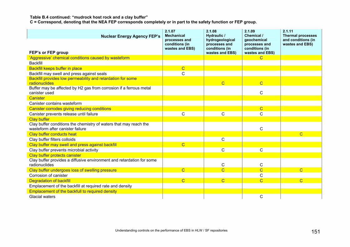
Understanding controls on the performance of EBS in HLW / SF repositories 151
Table B.4 continued: “mudrock host rock and a clay buffer” C = Correspond, denoting that the NEA FEP corresponds completely or in part to the safety function or FEP group.
Nuclear Energy Agency FEP’s
FEP’s or FEP group
2.1.07 Mechanical processes and conditions (in wastes and EBS)
2.1.08 Hydraulic / hydrogeological processes and conditions (in wastes and EBS)
2.1.09 Chemical / geochemical processes and conditions (in wastes and EBS)
2.1.11 Thermal processes and conditions (in wastes and EBS)
‘Aggressive’ chemical conditions caused by wasteform C Backfill Backfill keeps buffer in place C Backfill may swell and press against seals C Backfill provides low permeability and retardation for some radionuclides C C Buffer may be affected by H2 gas from corrosion if a ferrous metal canister used C Canister Canister contains wasteform Canister corrodes giving reducing conditions C Canister prevents release until failure C C C Clay buffer Clay buffer conditions the chemistry of waters that may reach the wasteform after canister failure C Clay buffer conducts heat C Clay buffer filters colloids C Clay buffer may swell and press against backfill C Clay buffer prevents microbial activity C C Clay buffer protects canister Clay buffer provides a diffusive environment and retardation for some radionuclides C C Clay buffer undergoes loss of swelling pressure C C C C Corrosion of canister C Degradation of backfill C C C C Emplacement of the backfill at required rate and density Emplacement of the backfull to required density Glacial waters C

Understanding controls on the performance of EBS in HLW / SF repositories 152
Nuclear Energy Agency FEP’s
FEP’s or FEP group
2.1.07 Mechanical processes and conditions (in wastes and EBS)
2.1.08 Hydraulic / hydrogeological processes and conditions (in wastes and EBS)
2.1.09 Chemical / geochemical processes and conditions (in wastes and EBS)
2.1.11 Thermal processes and conditions (in wastes and EBS)
Host rock conducts heat Host rock provides suitable groundwater flow and chemistry for buffer C Host rock provides suitable groundwater flow and chemistry, and retardation for some radionuclides. Host rock provides suitable groundwater flow field for backfill Host rock provides suitable stress and groundwater flow fields for seals C Host rock provides suitable stress, groundwater flows and chemistry for canister C Indurated mudstone host rock Initial defects in canister C Mechanical failure of canister C Possibly iron-bentonite interactions if a ferrous metal canister used C Possibly minor alteration of the host rock caused by the seal (e.g. by cement sealing materials) C Possibly minor reaction of the backfill with the host rock C Radiation effects from waste form on canister Radionuclide release from wasteform C Seal anchoring strength and degradation C C C Seal properties and degradation C C C Seal provides low permeability C Seals Seals prevent access Seals provide mechanical support for backfill C Seismic activity and shearing C Slow dissolution of waste form and release of radionuclides C C Unexpected ‘poor ground conditions’ Wasteform Does the NEA FEP correspond to at least one safety function / FEP group? Yes Yes Yes Yes
Table B.4 continued: “mudrock host rock and a clay buffer” C = Correspond, denoting that the NEA FEP corresponds completely or in part to the safety function or FEP group.

Understanding controls on the performance of EBS in HLW / SF repositories 153
Table B.4 continued: “mudrock host rock and a clay buffer” C = Correspond, denoting that the NEA FEP corresponds completely or in part to the safety function or FEP group.
Nuclear Energy Agency FEP’s
FEP’s or FEP group
2.1.12 Gas sources and effects (in wastes and EBS)
2.1.13 Radiation effects (in wastes and EBS)
2.2.01 Excavation disturbed zone / host rock
2.2.02 Host rock
2.2.04 Discontinuities, large scale (other)
2.2.05 Contaminant transport path characteristics (in geosphere)
‘Aggressive’ chemical conditions caused by wasteform Backfill Backfill keeps buffer in place Backfill may swell and press against seals Backfill provides low permeability and retardation for some radionuclides Buffer may be affected by H2 gas from corrosion if a ferrous metal canister used C Canister C Canister contains wasteform Canister corrodes giving reducing conditions C Canister prevents release until failure Clay buffer Clay buffer conditions the chemistry of waters that may reach the wasteform after canister failure Clay buffer conducts heat Clay buffer filters colloids Clay buffer may swell and press against backfill Clay buffer prevents microbial activity Clay buffer protects canister Clay buffer provides a diffusive environment and retardation for some radionuclides Clay buffer undergoes loss of swelling pressure Corrosion of canister C Degradation of backfill C Emplacement of the backfill at required rate and density Emplacement of the backfull to required density Glacial waters

Understanding controls on the performance of EBS in HLW / SF repositories 154
Nuclear Energy Agency FEP’s
FEP’s or FEP group
2.1.12 Gas sources and effects (in wastes and EBS)
2.1.13 Radiation effects (in wastes and EBS)
2.2.01 Excavation disturbed zone / host rock
2.2.02 Host rock
2.2.04 Discontinuities, large scale (other)
2.2.05 Contaminant transport path characteristics (in geosphere)
Host rock conducts heat Host rock provides suitable groundwater flow and chemistry for buffer C C C Host rock provides suitable groundwater flow and chemistry, and retardation for some radionuclides. C C Host rock provides suitable groundwater flow field for backfill C C C Host rock provides suitable stress and groundwater flow fields for seals C C C Host rock provides suitable stress, groundwater flows and chemistry for canister C C C Indurated mudstone host rock C Initial defects in canister Mechanical failure of canister Possibly iron-bentonite interactions if a ferrous metal canister used Possibly minor alteration of the host rock caused by the seal (e.g. by cement sealing materials) Possibly minor reaction of the backfill with the host rock Radiation effects from waste form on canister C Radionuclide release from wasteform Seal anchoring strength and degradation Seal properties and degradation Seal provides low permeability Seals Seals prevent access Seals provide mechanical support for backfill Seismic activity and shearing Slow dissolution of waste form and release of radionuclides Unexpected ‘poor ground conditions’ C Wasteform Does the NEA FEP correspond to at least one safety function / FEP group? Yes Yes Yes Yes Yes Yes
Table B.4 continued: “mudrock host rock and a clay buffer” C = Correspond, denoting that the NEA FEP corresponds completely or in part to the safety function or FEP group.

Understanding controls on the performance of EBS in HLW / SF repositories 155
Table B.4 continued: “mudrock host rock and a clay buffer” C = Correspond, denoting that the NEA FEP corresponds completely or in part to the safety function or FEP group.
Nuclear Energy Agency FEP’s
FEP’s or FEP group
2.2.06 Mechanical processes and conditions (in geosphere)
2.2.07 Hydraulic / hydrogeological processes and conditions (in geosphere)
2.2.08 Chemical / geochemical processes and conditions (in geosphere)
2.2.10 Thermal processes and conditions (in geosphere)
2.2.11 Gas sources and effects (in geosphere)
‘Aggressive’ chemical conditions caused by wasteform Backfill Backfill keeps buffer in place Backfill may swell and press against seals Backfill provides low permeability and retardation for some radionuclides Buffer may be affected by H2 gas from corrosion if a ferrous metal canister used Canister Canister contains wasteform Canister corrodes giving reducing conditions Canister prevents release until failure Clay buffer Clay buffer conditions the chemistry of waters that may reach the wasteform after canister failure Clay buffer conducts heat Clay buffer filters colloids Clay buffer may swell and press against backfill Clay buffer prevents microbial activity Clay buffer protects canister Clay buffer provides a diffusive environment and retardation for some radionuclides Clay buffer undergoes loss of swelling pressure Corrosion of canister Degradation of backfill Emplacement of the backfill at required rate and density Emplacement of the backfull to required density Glacial waters C

Understanding controls on the performance of EBS in HLW / SF repositories 156
Table B.4 continued: “mudrock host rock and a clay buffer” C = Correspond, denoting that the NEA FEP corresponds completely or in part to the safety function or FEP group.
Nuclear Energy Agency FEP’s
FEP’s or FEP group
2.2.06 Mechanical processes and conditions (in geosphere)
2.2.07 Hydraulic / hydrogeological processes and conditions (in geosphere)
2.2.08 Chemical / geochemical processes and conditions (in geosphere)
2.2.10 Thermal processes and conditions (in geosphere)
2.2.11 Gas sources and effects (in geosphere)
Host rock conducts heat C Host rock provides suitable groundwater flow and chemistry for buffer C C Host rock provides suitable groundwater flow and chemistry, and retardation for some radionuclides. C C C C Host rock provides suitable groundwater flow field for backfill C Host rock provides suitable stress and groundwater flow fields for seals C C Host rock provides suitable stress, groundwater flows and chemistry for canister C C C Indurated mudstone host rock Initial defects in canister Mechanical failure of canister C Possibly iron-bentonite interactions if a ferrous metal canister used Possibly minor alteration of the host rock caused by the seal (e.g. by cement sealing materials) C Possibly minor reaction of the backfill with the host rock C Radiation effects from waste form on canister Radionuclide release from wasteform Seal anchoring strength and degradation Seal properties and degradation Seal provides low permeability Seals Seals prevent access Seals provide mechanical support for backfill Seismic activity and shearing C Slow dissolution of waste form and release of radionuclides Unexpected ‘poor ground conditions’ C Wasteform Does the NEA FEP correspond to at least one safety function / FEP group? Yes Yes Yes Yes Yes

Understanding controls on the performance of EBS in HLW / SF repositories 157
Table B.4 continued: “mudrock host rock and a clay buffer” C = Correspond, denoting that the NEA FEP corresponds completely or in part to the safety function or FEP group.
Nuclear Energy Agency FEP’s
FEP’s or FEP group
3.1.01 Radioactive decay and in-growth
3.2.01 Dissolution, precipitation and crystallisation, contaminant
3.2.02 Speciation and solubility, contaminant
3.2.03 Sorption / desorption processes, contaminant
3.2.04 Colloids, contaminant interactions and transport with
‘Aggressive’ chemical conditions caused by wasteform C C C Backfill Backfill keeps buffer in place Backfill may swell and press against seals Backfill provides low permeability and retardation for some radionuclides C C C C Buffer may be affected by H2 gas from corrosion if a ferrous metal canister used Canister Canister contains wasteform Canister corrodes giving reducing conditions Canister prevents release until failure Clay buffer Clay buffer conditions the chemistry of waters that may reach the wasteform after canister failure Clay buffer conducts heat Clay buffer filters colloids Clay buffer may swell and press against backfill Clay buffer prevents microbial activity Clay buffer protects canister Clay buffer provides a diffusive environment and retardation for some radionuclides C C C C C Clay buffer undergoes loss of swelling pressure Corrosion of canister Degradation of backfill Emplacement of the backfill at required rate and density Emplacement of the backfull to required density Glacial waters

Understanding controls on the performance of EBS in HLW / SF repositories 158
Nuclear Energy Agency FEP’s
FEP’s or FEP group
3.1.01 Radioactive decay and in-growth
3.2.01 Dissolution, precipitation and crystallisation, contaminant
3.2.02 Speciation and solubility, contaminant
3.2.03 Sorption / desorption processes, contaminant
3.2.04 Colloids, contaminant interactions and transport with
Host rock conducts heat Host rock provides suitable groundwater flow and chemistry for buffer Host rock provides suitable groundwater flow and chemistry, and retardation for some radionuclides. C C Host rock provides suitable groundwater flow field for backfill Host rock provides suitable stress and groundwater flow fields for seals Host rock provides suitable stress, groundwater flows and chemistry for canister Indurated mudstone host rock Initial defects in canister Mechanical failure of canister Possibly iron-bentonite interactions if a ferrous metal canister used Possibly minor alteration of the host rock caused by the seal (e.g. by cement sealing materials) Possibly minor reaction of the backfill with the host rock Radiation effects from waste form on canister C Radionuclide release from wasteform C C C C Seal anchoring strength and degradation Seal properties and degradation Seal provides low permeability Seals Seals prevent access Seals provide mechanical support for backfill Seismic activity and shearing Slow dissolution of waste form and release of radionuclides C C C C Unexpected ‘poor ground conditions’ Wasteform Does the NEA FEP correspond to at least one safety function / FEP group? Yes Yes Yes Yes Yes

Understanding controls on the performance of EBS in HLW / SF repositories 159
Table B.4 continued: “mudrock host rock and a clay buffer” C = Correspond, denoting that the NEA FEP corresponds completely or in part to the safety function or FEP group.
Nuclear Energy Agency FEP’s
FEP’s or FEP group
3.2.05 Chemical / complexing agents, effects on contaminant speciation / transport
3.2.06 Microbial / biological / plant-mediated processes, contaminant
3.2.07 Water-mediated transport of contaminants
Does the safety function or FEP group correspond to at least one NEA FEP?
‘Aggressive’ chemical conditions caused by wasteform Yes Backfill Yes Backfill keeps buffer in place Yes Backfill may swell and press against seals Yes Backfill provides low permeability and retardation for some radionuclides C C C Yes Buffer may be affected by H2 gas from corrosion if a ferrous metal canister used Yes Canister Yes Canister contains wasteform Yes Canister corrodes giving reducing conditions Yes Canister prevents release until failure Yes Clay buffer Yes Clay buffer conditions the chemistry of waters that may reach the wasteform after canister failure Yes Clay buffer conducts heat Yes Clay buffer filters colloids Yes Clay buffer may swell and press against backfill Yes Clay buffer prevents microbial activity C Yes Clay buffer protects canister Yes Clay buffer provides a diffusive environment and retardation for some radionuclides C C C Yes Clay buffer undergoes loss of swelling pressure Yes Corrosion of canister Yes Degradation of backfill Yes Emplacement of the backfill at required rate and density Yes Emplacement of the backfull to required density Yes Glacial waters Yes

Understanding controls on the performance of EBS in HLW / SF repositories 160
Nuclear Energy Agency FEP’s
FEP’s or FEP group
3.2.05 Chemical / complexing agents, effects on contaminant speciation / transport
3.2.06 Microbial / biological / plant-mediated processes, contaminant
3.2.07 Water-mediated transport of contaminants
Does the safety function or FEP group correspond to at least one NEA FEP?
Host rock conducts heat Yes Host rock provides suitable groundwater flow and chemistry for buffer Yes Host rock provides suitable groundwater flow and chemistry, and retardation for some radionuclides. C Yes Host rock provides suitable groundwater flow field for backfill Yes Host rock provides suitable stress and groundwater flow fields for seals Yes Host rock provides suitable stress, groundwater flows and chemistry for canister Yes Indurated mudstone host rock Yes Initial defects in canister Yes Mechanical failure of canister Yes Possibly iron-bentonite interactions if a ferrous metal canister used Yes Possibly minor alteration of the host rock caused by the seal (e.g. by cement sealing materials) Yes Possibly minor reaction of the backfill with the host rock Yes Radiation effects from waste form on canister Yes Radionuclide release from wasteform C C Yes Seal anchoring strength and degradation Yes Seal properties and degradation Yes Seal provides low permeability Yes Seals Yes Seals prevent access Yes Seals provide mechanical support for backfill Yes Seismic activity and shearing Yes Slow dissolution of waste form and release of radionuclides C C Yes Unexpected ‘poor ground conditions’ Yes Wasteform Yes Does the NEA FEP correspond to at least one safety function / FEP group? Yes Yes Yes
Table B.4 continued: “mudrock host rock and a clay buffer” C = Correspond, denoting that the NEA FEP corresponds completely or in part to the safety function or FEP group.

Understanding controls on the performance of EBS in HLW / SF repositories 161
Table B.5 Comparison between the FEPs and FEP groups for the “mudrock host rock and a supercontainer with a cement buffer” (Table 5.4) and the NEA’s FEPs in Table B.2.
C = Correspond, denoting that the NEA FEP corresponds completely or in part to the safety function or FEP group.
Nuclear Energy Agency FEP’s
FEP’s or FEP group
1.1.03 Emplacement of wastes and backfilling
1.1.04 Closure and repository sealing
1.1.07 Repository design
1.1.08 Quality control
1.1.09 Schedule and planning
1.2.02 Deformation, elastic, plastic or brittle
Buffer may be affected by H2 gas from corrosion if a ferrous metal canister used Cement buffer C C Cement buffer causes localised chemical alteration of the host rock immediately outside the supercontainer Cement buffer conditions high pH Cement buffer conducts heat Cement buffer limits chemical species migration Cement buffer prevents rapid localised corrosion and microbial activity Cement buffer conditions high-pH, passivates the envelope and minimises corrosion Cement buffer limits migration of some radionuclides Early seal emplacement allows rapid re-saturation and prevents excessive host rock deformation or oxidation C C C Heat from the steel overpack may affect the moisture content and solid phases of the cement buffer High pH caused by cement buffer may enhance glass dissolution after overpack failure Host rock conducts heat Host rock provides a low permeability, preferable diffusive barrier to radionuclide migration Host rock provides suitable stress and groundwater flow fields for seals Host rock sorbs some radionuclides Migration of aggressive species from the host rock may corrode the envelope Mudstone host rock C Mudstone host rock allows gas escape Radiation effects from waste form on overpack

Understanding controls on the performance of EBS in HLW / SF repositories 162
Nuclear Energy Agency FEP’s
FEP’s or FEP group
1.1.03 Emplacement of wastes and backfilling
1.1.04 Closure and repository sealing
1.1.07 Repository design
1.1.08 Quality control
1.1.09 Schedule and planning
1.2.02 Deformation, elastic, plastic or brittle
Radionuclide release from wasteform Seal properties and degradation C Seal provides low hydraulic conductivity C Seal provides low permeability C Seals C C C Seals prevent access C Slow dissolution of waste form and release of radionuclides Steel overpack C C Steel overpack provides complete containment for the thermal phase Steel overpack corrodes predictably and gives reducing conditions Supercontainer envelope C C Supercontainer envelope conducts heat Supercontainer envelope facilitates fabrication of buffer and handling and emplacement of the supercontainer C C Supercontainer may limit chemical alteration of the host rock by the cement buffer Unexpected ‘poor ground conditions’ C Wasteform C C Does the NEA FEP correspond to at least one safety function / FEP group? Yes Yes Yes Yes Yes Yes
Table B.5 continued: “mudrock host rock and a supercontainer with a cement buffer” C = Correspond, denoting that the NEA FEP corresponds completely or in part to the safety function or FEP group.

Understanding controls on the performance of EBS in HLW / SF repositories 163
Table B.5 continued: “mudrock host rock and a supercontainer with a cement buffer” C = Correspond, denoting that the NEA FEP corresponds completely or in part to the safety function or FEP group.
Nuclear Energy Agency FEP’s
FEP’s or FEP group
1.2.03 Seismicity
1.2.09 Salt diapirism and dissolution
1.2.10 Hydrological / hydrogeological response to geological changes
1.3.07 Hydrological / hydrogeological response to climate changes
2.1.01 Inventory, radionuclide and other material
Buffer may be affected by H2 gas from corrosion if a ferrous metal canister used Cement buffer Cement buffer causes localised chemical alteration of the host rock immediately outside the supercontainer Cement buffer conditions high pH Cement buffer conducts heat Cement buffer limits chemical species migration Cement buffer prevents rapid localised corrosion and microbial activity Cement buffer conditions high-pH, passivates the envelope and minimises corrosion Cement buffer limits migration of some radionuclides Early seal emplacement allows rapid re-saturation and prevents excessive host rock deformation or oxidation Heat from the steel overpack may affect the moisture content and solid phases of the cement buffer High pH caused by cement buffer may enhance glass dissolution after overpack failure Host rock conducts heat Host rock provides a low permeability, preferable diffusive barrier to radionuclide migration C C Host rock provides suitable stress and groundwater flow fields for seals C C Host rock sorbs some radionuclides Migration of aggressive species from the host rock may corrode the envelope Mudstone host rock Mudstone host rock allows gas escape Radiation effects from waste form on overpack

Understanding controls on the performance of EBS in HLW / SF repositories 164
Nuclear Energy Agency FEP’s
FEP’s or FEP group
1.2.03 Seismicity
1.2.09 Salt diapirism and dissolution
1.2.10 Hydrological / hydrogeological response to geological changes
1.3.07 Hydrological / hydrogeological response to climate changes
2.1.01 Inventory, radionuclide and other material
Radionuclide release from wasteform C Seal properties and degradation Seal provides low hydraulic conductivity Seal provides low permeability Seals Seals prevent access Slow dissolution of waste form and release of radionuclides Steel overpack Steel overpack provides complete containment for the thermal phase Steel overpack corrodes predictably and gives reducing conditions Supercontainer envelope Supercontainer envelope conducts heat Supercontainer envelope facilitates fabrication of buffer and handling and emplacement of the supercontainer Supercontainer may limit chemical alteration of the host rock by the cement buffer Unexpected ‘poor ground conditions’ Wasteform C Does the NEA FEP correspond to at least one safety function / FEP group? No No Yes Yes Yes
Table B.5 continued: “mudrock host rock and a supercontainer with a cement buffer” C = Correspond, denoting that the NEA FEP corresponds completely or in part to the safety function or FEP group.

Understanding controls on the performance of EBS in HLW / SF repositories 165
Table B.5 continued: “mudrock host rock and a supercontainer with a cement buffer” C = Correspond, denoting that the NEA FEP corresponds completely or in part to the safety function or FEP group.
Nuclear Energy Agency FEP’s
FEP’s or FEP group
2.1.02 Waste form materials and characteristics
2.1.03 Container materials and characteristics
2.1.04 Buffer / backfill materials and characteristics
2.1.05 Seals cavern/ tunnel/ shaft
2.1.06 Other engineered materials features and characteristics
Buffer may be affected by H2 gas from corrosion if a ferrous metal canister used C C Cement buffer C Cement buffer causes localised chemical alteration of the host rock immediately outside the supercontainer C Cement buffer conditions high pH C Cement buffer conducts heat C Cement buffer limits chemical species migration C Cement buffer prevents rapid localised corrosion and microbial activity C Cement buffer conditions high-pH, passivates the envelope and minimises corrosion C Cement buffer limits migration of some radionuclides C Early seal emplacement allows rapid re-saturation and prevents excessive host rock deformation or oxidation C Heat from the steel overpack may affect the moisture content and solid phases of the cement buffer High pH caused by cement buffer may enhance glass dissolution after overpack failure C Host rock conducts heat Host rock provides a low permeability, preferable diffusive barrier to radionuclide migration Host rock provides suitable stress and groundwater flow fields for seals Host rock sorbs some radionuclides Migration of aggressive species from the host rock may corrode the envelope C Mudstone host rock Mudstone host rock allows gas escape Radiation effects from waste form on overpack C C

Understanding controls on the performance of EBS in HLW / SF repositories 166
Nuclear Energy Agency FEP’s
FEP’s or FEP group
2.1.02 Waste form materials and characteristics
2.1.03 Container materials and characteristics
2.1.04 Buffer / backfill materials and characteristics
2.1.05 Seals cavern/ tunnel/ shaft
2.1.06 Other engineered materials features and characteristics
Radionuclide release from wasteform C Seal properties and degradation C Seal provides low hydraulic conductivity C Seal provides low permeability C Seals C Seals prevent access C Slow dissolution of waste form and release of radionuclides C Steel overpack C Steel overpack provides complete containment for the thermal phase C Steel overpack corrodes predictably and gives reducing conditions C Supercontainer envelope C Supercontainer envelope conducts heat Supercontainer envelope facilitates fabrication of buffer and handling and emplacement of the supercontainer C C Supercontainer may limit chemical alteration of the host rock by the cement buffer Unexpected ‘poor ground conditions’ Wasteform C Does the NEA FEP correspond to at least one safety function / FEP group? Yes Yes Yes Yes Yes
Table B.5 continued: “mudrock host rock and a supercontainer with a cement buffer” C = Correspond, denoting that the NEA FEP corresponds completely or in part to the safety function or FEP group.

Table B.5 continued: “mudrock host rock and a supercontainer with a cement buffer” C = Correspond, denoting that the NEA FEP corresponds completely or in part to the safety function or FEP group.
Nuclear Energy Agency FEP’s
FEP’s or FEP group
2.1.07 Mechanical processes and conditions (in wastes and EBS)
2.1.08 Hydraulic / hydrogeological processes and conditions (in wastes and EBS)
2.1.09 Chemical / geochemical processes and conditions (in wastes and EBS)
2.1.11 Thermal processes and conditions (in wastes and EBS)
Buffer may be affected by H2 gas from corrosion if a ferrous metal canister used C Cement buffer Cement buffer causes localised chemical alteration of the host rock immediately outside the supercontainer C Cement buffer conditions high pH C Cement buffer conducts heat C Cement buffer limits chemical species migration C Cement buffer prevents rapid localised corrosion and microbial activity C C Cement buffer conditions high-pH, passivates the envelope and minimises corrosion C Cement buffer limits migration of some radionuclides C C Early seal emplacement allows rapid re-saturation and prevents excessive host rock deformation or oxidation C C C Heat from the steel overpack may affect the moisture content and solid phases of the cement buffer C C High pH caused by cement buffer may enhance glass dissolution after overpack failure C Host rock conducts heat Host rock provides a low permeability, preferable diffusive barrier to radionuclide migration Host rock provides suitable stress and groundwater flow fields for seals C Host rock sorbs some radionuclides Migration of aggressive species from the host rock may corrode the envelope C Mudstone host rock Mudstone host rock allows gas escape Radiation effects from waste form on overpack
167

Table B.5 continued: “mudrock host rock and a supercontainer with a cement buffer” C = Correspond, denoting that the NEA FEP corresponds completely or in part to the safety function or FEP group.
Nuclear Energy Agency FEP’s
FEP’s or FEP group
2.1.07 Mechanical processes and conditions (in wastes and EBS)
2.1.08 Hydraulic / hydrogeological processes and conditions (in wastes and EBS)
2.1.09 Chemical / geochemical processes and conditions (in wastes and EBS)
2.1.11 Thermal processes and conditions (in wastes and EBS)
Radionuclide release from wasteform C Seal properties and degradation C C C Seal provides low hydraulic conductivity C Seal provides low permeability C Seals Seals prevent access Slow dissolution of waste form and release of radionuclides C C Steel overpack Steel overpack provides complete containment for the thermal phase Steel overpack corrodes predictably and gives reducing conditions C Supercontainer envelope Supercontainer envelope conducts heat C Supercontainer envelope facilitates fabrication of buffer and handling and emplacement of the supercontainer Supercontainer may limit chemical alteration of the host rock by the cement buffer C C C Unexpected ‘poor ground conditions’ Wasteform Does the NEA FEP correspond to at least one safety function / FEP group? Yes Yes Yes Yes
168

Understanding controls on the performance of EBS in HLW / SF repositories 169
Table B.5 continued: “mudrock host rock and a supercontainer with a cement buffer” C = Correspond, denoting that the NEA FEP corresponds completely or in part to the safety function or FEP group.
Nuclear Energy Agency FEP’s
FEP’s or FEP group
2.1.12 Gas sources and effects (in wastes and EBS)
2.1.13 Radiation effects (in wastes and EBS)
2.2.01 Excavation disturbed zone / host rock
2.2.02 Host rock
2.2.04 Discontinuities, large scale (other)
2.2.05 Contaminant transport path characteristics (in geosphere)
Buffer may be affected by H2 gas from corrosion if a ferrous metal canister used C Cement buffer Cement buffer causes localised chemical alteration of the host rock immediately outside the supercontainer Cement buffer conditions high pH Cement buffer conducts heat Cement buffer limits chemical species migration Cement buffer prevents rapid localised corrosion and microbial activity C Cement buffer conditions high-pH, passivates the envelope and minimises corrosion Cement buffer limits migration of some radionuclides Early seal emplacement allows rapid re-saturation and prevents excessive host rock deformation or oxidation Heat from the steel overpack may affect the moisture content and solid phases of the cement buffer High pH caused by cement buffer may enhance glass dissolution after overpack failure Host rock conducts heat Host rock provides a low permeability, preferable diffusive barrier to radionuclide migration C C Host rock provides suitable stress and groundwater flow fields for seals C C C Host rock sorbs some radionuclides C Migration of aggressive species from the host rock may corrode the envelope Mudstone host rock C Mudstone host rock allows gas escape C Radiation effects from waste form on overpack C

Understanding controls on the performance of EBS in HLW / SF repositories 170
Nuclear Energy Agency FEP’sFEP’s or FEP group
2.1.12 Gas sources and effects (in wastes and EBS)
2.1.13 Radiation effects (in wastes and EBS)
2.2.01 Excavation disturbed zone / host rock
2.2.02 Host rock
2.2.04 Discontinuities, large scale (other)
2.2.05 Contaminant transport path characteristics (in geosphere)
Radionuclide release from wasteform Seal properties and degradation Seal provides low hydraulic conductivity Seal provides low permeability Seals Seals prevent access Slow dissolution of waste form and release of radionuclides Steel overpack C Steel overpack provides complete containment for the thermal phase Steel overpack corrodes predictably and gives reducing conditions C Supercontainer envelope Supercontainer envelope conducts heat Supercontainer envelope facilitates fabrication of buffer and handling and emplacement of the supercontainer Supercontainer may limit chemical alteration of the host rock by the cement buffer Unexpected ‘poor ground conditions’ C Wasteform Does the NEA FEP correspond to at least one safety function / FEP group? Yes Yes Yes Yes Yes Yes
Table B.5 continued: “mudrock host rock and a supercontainer with a cement buffer” C = Correspond, denoting that the NEA FEP corresponds completely or in part to the safety function or FEP group.

Understanding controls on the performance of EBS in HLW / SF repositories 171
Table B.5 continued: “mudrock host rock and a supercontainer with a cement buffer” C = Correspond, denoting that the NEA FEP corresponds completely or in part to the safety function or FEP group.
Nuclear Energy Agency FEP’s
FEP’s or FEP group
2.2.06 Mechanical processes and conditions (in geosphere)
2.2.07 Hydraulic / hydrogeological processes and conditions (in geosphere)
2.2.08 Chemical / geochemical processes and conditions (in geosphere)
2.2.10 Thermal processes and conditions (in geosphere)
2.2.11 Gas sources and effects (in geosphere)
Buffer may be affected by H2 gas from corrosion if a ferrous metal canister used Cement buffer Cement buffer causes localised chemical alteration of the host rock immediately outside the supercontainer Cement buffer conditions high pH Cement buffer conducts heat Cement buffer limits chemical species migration Cement buffer prevents rapid localised corrosion and microbial activity Cement buffer conditions high-pH, passivates the envelope and minimises corrosion Cement buffer limits migration of some radionuclides Early seal emplacement allows rapid re-saturation and prevents excessive host rock deformation or oxidation Heat from the steel overpack may affect the moisture content and solid phases of the cement buffer High pH caused by cement buffer may enhance glass dissolution after overpack failure Host rock conducts heat C Host rock provides a low permeability, preferable diffusive barrier to radionuclide migration C C Host rock provides suitable stress and groundwater flow fields for seals C C Host rock sorbs some radionuclides C Migration of aggressive species from the host rock may corrode the envelope C Mudstone host rock Mudstone host rock allows gas escape C C C Radiation effects from waste form on overpack

Understanding controls on the performance of EBS in HLW / SF repositories 172
Nuclear Energy Agency FEP’s
FEP’s or FEP group
2.2.06 Mechanical processes and conditions (in geosphere)
2.2.07 Hydraulic / hydrogeological processes and conditions (in geosphere)
2.2.08 Chemical / geochemical processes and conditions (in geosphere)
2.2.10 Thermal processes and conditions (in geosphere)
2.2.11 Gas sources and effects (in geosphere)
Radionuclide release from wasteform Seal properties and degradation Seal provides low hydraulic conductivity Seal provides low permeability Seals Seals prevent access Slow dissolution of waste form and release of radionuclides Steel overpack Steel overpack provides complete containment for the thermal phase Steel overpack corrodes predictably and gives reducing conditions Supercontainer envelope Supercontainer envelope conducts heat Supercontainer envelope facilitates fabrication of buffer and handling and emplacement of the supercontainer Supercontainer may limit chemical alteration of the host rock by the cement buffer C C Unexpected ‘poor ground conditions’ C Wasteform Does the NEA FEP correspond to at least one safety function / FEP group? Yes Yes Yes Yes Yes
Table B.5 continued: “mudrock host rock and a supercontainer with a cement buffer” C = Correspond, denoting that the NEA FEP corresponds completely or in part to the safety function or FEP group.

Understanding controls on the performance of EBS in HLW / SF repositories 173
Table B.5 continued: “mudrock host rock and a supercontainer with a cement buffer” C = Correspond, denoting that the NEA FEP corresponds completely or in part to the safety function or FEP group.
Nuclear Energy Agency FEP’s
FEP’s or FEP group
3.1.01 Radioactive decay and in-growth
3.2.01 Dissolution, precipitation and crystallisation, contaminant
3.2.02 Speciation and solubility, contaminant
3.2.03 Sorption / desorption processes, contaminant
3.2.04 Colloids, contaminant interactions and transport with
Buffer may be affected by H2 gas from corrosion if a ferrous metal canister used Cement buffer Cement buffer causes localised chemical alteration of the host rock immediately outside the supercontainer C C C Cement buffer conditions high pH Cement buffer conducts heat Cement buffer limits chemical species migration C C C C Cement buffer prevents rapid localised corrosion and microbial activity Cement buffer conditions high-pH, passivates the envelope and minimises corrosion Cement buffer limits migration of some radionuclides C C C C C Early seal emplacement allows rapid re-saturation and prevents excessive host rock deformation or oxidation Heat from the steel overpack may affect the moisture content and solid phases of the cement buffer High pH caused by cement buffer may enhance glass dissolution after overpack failure Host rock conducts heat Host rock provides a low permeability, preferable diffusive barrier to radionuclide migration Host rock provides suitable stress and groundwater flow fields for seals Host rock sorbs some radionuclides C Migration of aggressive species from the host rock may corrode the envelope Mudstone host rock Mudstone host rock allows gas escape Radiation effects from waste form on overpack C

Understanding controls on the performance of EBS in HLW / SF repositories 174
Nuclear Energy Agency FEP’sFEP’s or FEP group
3.1.01 Radioactive decay and in-growth
3.2.01 Dissolution, precipitation and crystallisation, contaminant
3.2.02 Speciation and solubility, contaminant
3.2.03 Sorption / desorption processes, contaminant
3.2.04 Colloids, contaminant interactions and transport with
Radionuclide release from wasteform C C C C Seal properties and degradation Seal provides low hydraulic conductivity Seal provides low permeability Seals Seals prevent access Slow dissolution of waste form and release of radionuclides C C C C Steel overpack Steel overpack provides complete containment for the thermal phase Steel overpack corrodes predictably and gives reducing conditions Supercontainer envelope Supercontainer envelope conducts heat Supercontainer envelope facilitates fabrication of buffer and handling and emplacement of the supercontainer Supercontainer may limit chemical alteration of the host rock by the cement buffer Unexpected ‘poor ground conditions’ Wasteform Does the NEA FEP correspond to at least one safety function / FEP group? Yes Yes Yes Yes Yes
Table B.5 continued: “mudrock host rock and a supercontainer with a cement buffer” C = Correspond, denoting that the NEA FEP corresponds completely or in part to the safety function or FEP group.

Understanding controls on the performance of EBS in HLW / SF repositories 175
Table B.5 continued: “mudrock host rock and a supercontainer with a cement buffer” C = Correspond, denoting that the NEA FEP corresponds completely or in part to the safety function or FEP group.
Nuclear Energy Agency FEP’s
FEP’s or FEP group
3.2.05 Chemical / complexing agents, effects on contaminant speciation / transport
3.2.06 Microbial / biological / plant-mediated processes, contaminant
3.2.07 Water-mediated transport of contaminants
Does the safety function or FEP group correspond to at least one NEA FEP?
Buffer may be affected by H2 gas from corrosion if a ferrous metal canister used Yes Cement buffer Yes Cement buffer causes localised chemical alteration of the host rock immediately outside the supercontainer Yes Cement buffer conditions high pH Yes Cement buffer conducts heat Yes Cement buffer limits chemical species migration C C C Yes Cement buffer prevents rapid localised corrosion and microbial activity C Yes Cement buffer conditions high-pH, passivates the envelope and minimises corrosion Yes Cement buffer limits migration of some radionuclides C C C Yes Early seal emplacement allows rapid re-saturation and prevents excessive host rock deformation or oxidation Yes Heat from the steel overpack may affect the moisture content and solid phases of the cement buffer Yes High pH caused by cement buffer may enhance glass dissolution after overpack failure Yes Host rock conducts heat Yes Host rock provides a low permeability, preferable diffusive barrier to radionuclide migration Yes Host rock provides suitable stress and groundwater flow fields for seals Yes Host rock sorbs some radionuclides Yes Migration of aggressive species from the host rock may corrode the envelope Yes Mudstone host rock Yes Mudstone host rock allows gas escape C Yes Radiation effects from waste form on overpack Yes

Understanding controls on the performance of EBS in HLW / SF repositories 176
Nuclear Energy Agency FEP’s
FEP’s or FEP group
3.2.05 Chemical / complexing agents, effects on contaminant speciation / transport
3.2.06 Microbial / biological / plant-mediated processes, contaminant
3.2.07 Water-mediated transport of contaminants
Does the safety function or FEP group correspond to at least one NEA FEP?
Radionuclide release from wasteform C C Yes Seal properties and degradation Yes Seal provides low hydraulic conductivity Yes Seal provides low permeability Yes Seals Yes Seals prevent access Yes Slow dissolution of waste form and release of radionuclides C C Yes Steel overpack Yes Steel overpack provides complete containment for the thermal phase Yes Steel overpack corrodes predictably and gives reducing conditions Yes Supercontainer envelope Yes Supercontainer envelope conducts heat Yes Supercontainer envelope facilitates fabrication of buffer and handling and emplacement of the supercontainer Yes Supercontainer may limit chemical alteration of the host rock by the cement buffer Yes Unexpected ‘poor ground conditions’ Yes Wasteform Yes Does the NEA FEP correspond to at least one safety function / FEP group? Yes Yes Yes

Understanding controls on the performance of EBS in HLW / SF repositories 177
Table B.6 Comparison between the FEPs and FEP groups for the “evaporite host rock and a salt backfill” (Table 5.5) and the NEA’s FEPs in Table B.2.
C = Correspond, denoting that the NEA FEP corresponds completely or in part to the safety function or FEP group.
Nuclear Energy Agency FEP’s
FEP’s or FEP group
1.1.03 Emplacement of wastes and backfilling
1.1.04 Closure and repository sealing
1.1.07 Repository design
1.1.08 Quality control
1.1.09 Schedule and planning
1.2.02 Deformation, elastic, plastic or brittle
Backfill conducts heat C C Backfill fills tunnels and prevents water from reaching the canister C C Backfill provides low hydraulic conductivity C C Brine pockets in host rock Canister C C Canister contains wasteform Canister prevents release until failure Corrosion of canister Emplacement of the backfill to required density C C C Evaporite host rock C C Gas generation by canister Gas pockets in host rock Host rock conducts heat Host rock creeps and compresses backfill C Host rock prevents water from reaching the canister Host rock prevents water from being able to leach radionuclides Host rock provides suitable stress field for seals Initial defects in canister C Interbeds in host rock Mechanical failure of canister Minor corrosion of canister giving reducing conditions Poor backfilling C C C Possibly minor alteration of the host rock caused by the seal (e.g. by cement sealing materials) Radiation effects from waste form on canister Radionuclide release from wasteform

Understanding controls on the performance of EBS in HLW / SF repositories 178
Nuclear Energy Agency FEP’s
FEP’s or FEP group
1.1.03 Emplacement of wastes and backfilling
1.1.04 Closure and repository sealing
1.1.07 Repository design
1.1.08 Quality control
1.1.09 Schedule and planning
1.2.02 Deformation, elastic, plastic or brittle
Salt backfill C C C C Seals C C C Seal anchoring strength and degradation C C Seal essentially prevents water from reaching the canister C Seals prevent access C Seals prevent water flow C Seal properties and degradation C Seals provide low hydraulic conductivity C Seals provide mechanical support for backfill C Slow dissolution of waste form and release of radionuclides Stability of HLW glass in brine Unexpected ‘poor ground conditions’ C Thermo-hydro-mechanical behaviour of the backfill driven by heat from the canister C Wasteform C C Water inflow to canister Does the NEA FEP correspond to at least one safety function / FEP group? Yes Yes Yes Yes No Yes
Table B.6 continued: “evaporite host rock and a salt backfill” C = Correspond, denoting that the NEA FEP corresponds completely or in part to the safety function or FEP group.

Understanding controls on the performance of EBS in HLW / SF repositories 179
Table B.6 continued: “evaporite host rock and a salt backfill” C = Correspond, denoting that the NEA FEP corresponds completely or in part to the safety function or FEP group.
Nuclear Energy Agency FEP’s
FEP’s or FEP group
1.2.03 Seismicity
1.2.09 Salt diapirism and dissolution
1.2.10 Hydrological / hydrogeological response to geological changes
1.3.07 Hydrological / hydrogeological response to climate changes
2.1.01 Inventory, radionuclide and other material
Backfill conducts heat Backfill fills tunnels and prevents water from reaching the canister Backfill provides low hydraulic conductivity Brine pockets in host rock Canister Canister contains wasteform Canister prevents release until failure Corrosion of canister Emplacement of the backfill to required density Evaporite host rock C Gas generation by canister Gas pockets in host rock Host rock conducts heat Host rock creeps and compresses backfill C C C Host rock prevents water from reaching the canister Host rock prevents water from being able to leach radionuclides Host rock provides suitable stress field for seals Initial defects in canister Interbeds in host rock Mechanical failure of canister Minor corrosion of canister giving reducing conditions Poor backfilling Possibly minor alteration of the host rock caused by the seal (e.g. by cement sealing materials) Radiation effects from waste form on canister Radionuclide release from wasteform C

Understanding controls on the performance of EBS in HLW / SF repositories 180
Nuclear Energy Agency FEP’s
FEP’s or FEP group
1.2.03 Seismicity
1.2.09 Salt diapirism and dissolution
1.2.10 Hydrological / hydrogeological response to geological changes
1.3.07 Hydrological / hydrogeological response to climate changes
2.1.01 Inventory, radionuclide and other material
Salt backfill Seals Seal anchoring strength and degradation Seal essentially prevents water from reaching the canister Seals prevent access Seals prevent water flow Seal properties and degradation Seals provide low hydraulic conductivity Seals provide mechanical support for backfill Slow dissolution of waste form and release of radionuclides Stability of HLW glass in brine Unexpected ‘poor ground conditions’ Thermo-hydro-mechanical behaviour of the backfill driven by heat from the canister Wasteform C Water inflow to canister Does the NEA FEP correspond to at least one safety function / FEP group? No Yes Yes Yes Yes
Table B.6 continued: “evaporite host rock and a salt backfill” C = Correspond, denoting that the NEA FEP corresponds completely or in part to the safety function or FEP group.

Understanding controls on the performance of EBS in HLW / SF repositories 181
Table B.6 continued: “evaporite host rock and a salt backfill” C = Correspond, denoting that the NEA FEP corresponds completely or in part to the safety function or FEP group.
Nuclear Energy Agency FEP’s
FEP’s or FEP group
2.1.02 Waste form materials and characteristics
2.1.03 Container materials and characteristics
2.1.04 Buffer / backfill materials and characteristics
2.1.05 Seals cavern/ tunnel/ shaft
2.1.06 Other engineered materials features and characteristics
Backfill conducts heat C Backfill fills tunnels and prevents water from reaching the canister C Backfill provides low hydraulic conductivity C Brine pockets in host rock Canister C Canister contains wasteform C C Canister prevents release until failure C Corrosion of canister C Emplacement of the backfill to required density C Evaporite host rock Gas generation by canister C Gas pockets in host rock Host rock conducts heat Host rock creeps and compresses backfill Host rock prevents water from reaching the canister Host rock prevents water from being able to leach radionuclides Host rock provides suitable stress field for seals Initial defects in canister C Interbeds in host rock Mechanical failure of canister C Minor corrosion of canister giving reducing conditions C Poor backfilling Possibly minor alteration of the host rock caused by the seal (e.g. by cement sealing materials) Radiation effects from waste form on canister C C Radionuclide release from wasteform C

Understanding controls on the performance of EBS in HLW / SF repositories 182
Nuclear Energy Agency FEP’s
FEP’s or FEP group
2.1.02 Waste form materials and characteristics
2.1.03 Container materials and characteristics
2.1.04 Buffer / backfill materials and characteristics
2.1.05 Seals cavern/ tunnel/ shaft
2.1.06 Other engineered materials features and characteristics
Salt backfill C Seals C Seal anchoring strength and degradation C Seal essentially prevents water from reaching the canister C Seals prevent access C Seals prevent water flow C Seal properties and degradation C Seals provide low hydraulic conductivity C Seals provide mechanical support for backfill C Slow dissolution of waste form and release of radionuclides C Stability of HLW glass in brine C Unexpected ‘poor ground conditions’ Thermo-hydro-mechanical behaviour of the backfill driven by heat from the canister C Wasteform C Water inflow to canister Does the NEA FEP correspond to at least one safety function / FEP group? Yes Yes Yes Yes No
Table B.6 continued: “evaporite host rock and a salt backfill” C = Correspond, denoting that the NEA FEP corresponds completely or in part to the safety function or FEP group.
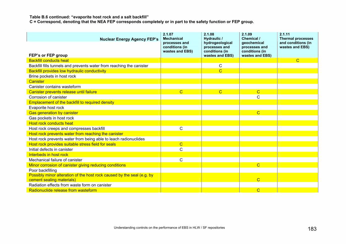
Understanding controls on the performance of EBS in HLW / SF repositories 183
Table B.6 continued: “evaporite host rock and a salt backfill” C = Correspond, denoting that the NEA FEP corresponds completely or in part to the safety function or FEP group.
Nuclear Energy Agency FEP’s
FEP’s or FEP group
2.1.07 Mechanical processes and conditions (in wastes and EBS)
2.1.08 Hydraulic / hydrogeological processes and conditions (in wastes and EBS)
2.1.09 Chemical / geochemical processes and conditions (in wastes and EBS)
2.1.11 Thermal processes and conditions (in wastes and EBS)
Backfill conducts heat C Backfill fills tunnels and prevents water from reaching the canister C Backfill provides low hydraulic conductivity C Brine pockets in host rock Canister Canister contains wasteform Canister prevents release until failure C C C Corrosion of canister C Emplacement of the backfill to required density Evaporite host rock Gas generation by canister C Gas pockets in host rock Host rock conducts heat Host rock creeps and compresses backfill C Host rock prevents water from reaching the canister Host rock prevents water from being able to leach radionuclides Host rock provides suitable stress field for seals C Initial defects in canister C Interbeds in host rock Mechanical failure of canister C Minor corrosion of canister giving reducing conditions C Poor backfilling Possibly minor alteration of the host rock caused by the seal (e.g. by cement sealing materials) C Radiation effects from waste form on canister Radionuclide release from wasteform C

Understanding controls on the performance of EBS in HLW / SF repositories 184
Nuclear Energy Agency FEP’s
FEP’s or FEP group
2.1.07 Mechanical processes and conditions (in wastes and EBS)
2.1.08 Hydraulic / hydrogeological processes and conditions (in wastes and EBS)
2.1.09 Chemical / geochemical processes and conditions (in wastes and EBS)
2.1.11 Thermal processes and conditions (in wastes and EBS)
Salt backfill Seals Seal anchoring strength and degradation C C C Seal essentially prevents water from reaching the canister C Seals prevent access Seals prevent water flow C Seal properties and degradation C C C Seals provide low hydraulic conductivity C Seals provide mechanical support for backfill C Slow dissolution of waste form and release of radionuclides C C Stability of HLW glass in brine C Unexpected ‘poor ground conditions’ Thermo-hydro-mechanical behaviour of the backfill driven by heat from the canister C C C C Wasteform Water inflow to canister C Does the NEA FEP correspond to at least one safety function / FEP group? Yes Yes Yes Yes
Table B.6 continued: “evaporite host rock and a salt backfill” C = Correspond, denoting that the NEA FEP corresponds completely or in part to the safety function or FEP group.

Understanding controls on the performance of EBS in HLW / SF repositories 185
Table B.6 continued: “evaporite host rock and a salt backfill” C = Correspond, denoting that the NEA FEP corresponds completely or in part to the safety function or FEP group.
Nuclear Energy Agency FEP’s
FEP’s or FEP group
2.1.12 Gas sources and effects (in wastes and EBS)
2.1.13 Radiation effects (in wastes and EBS)
2.2.01 Excavation disturbed zone / host rock
2.2.02 Host rock
2.2.04 Discontinuities, large scale (other)
2.2.05 Contaminant transport path characteristics (in geosphere)
Backfill conducts heat Backfill fills tunnels and prevents water from reaching the canister Backfill provides low hydraulic conductivity Brine pockets in host rock Canister C Canister contains wasteform Canister prevents release until failure Corrosion of canister C Emplacement of the backfill to required density Evaporite host rock C Gas generation by canister C Gas pockets in host rock Host rock conducts heat Host rock creeps and compresses backfill Host rock prevents water from reaching the canister Host rock prevents water from being able to leach radionuclides Host rock provides suitable stress field for seals Initial defects in canister Interbeds in host rock C C Mechanical failure of canister Minor corrosion of canister giving reducing conditions C Poor backfilling Possibly minor alteration of the host rock caused by the seal (e.g. by cement sealing materials) Radiation effects from waste form on canister C Radionuclide release from wasteform

Understanding controls on the performance of EBS in HLW / SF repositories 186
Nuclear Energy Agency FEP’s
FEP’s or FEP group
2.1.12 Gas sources and effects (in wastes and EBS)
2.1.13 Radiation effects (in wastes and EBS)
2.2.01 Excavation disturbed zone / host rock
2.2.02 Host rock
2.2.04 Discontinuities, large scale (other)
2.2.05 Contaminant transport path characteristics (in geosphere)
Salt backfill Seals Seal anchoring strength and degradation Seal essentially prevents water from reaching the canister Seals prevent access Seals prevent water flow Seal properties and degradation Seals provide low hydraulic conductivity Seals provide mechanical support for backfill Slow dissolution of waste form and release of radionuclides Stability of HLW glass in brine Unexpected ‘poor ground conditions’ C Thermo-hydro-mechanical behaviour of the backfill driven by heat from the canister Wasteform Water inflow to canister Does the NEA FEP correspond to at least one safety function / FEP group? Yes Yes No Yes Yes No
Table B.6 continued: “evaporite host rock and a salt backfill” C = Correspond, denoting that the NEA FEP corresponds completely or in part to the safety function or FEP group.

Understanding controls on the performance of EBS in HLW / SF repositories 187
Table B.6 continued: “evaporite host rock and a salt backfill” C = Correspond, denoting that the NEA FEP corresponds completely or in part to the safety function or FEP group.
Nuclear Energy Agency FEP’s
FEP’s or FEP group
2.2.06 Mechanical processes and conditions (in geosphere)
2.2.07 Hydraulic / hydrogeological processes and conditions (in geosphere)
2.2.08 Chemical / geochemical processes and conditions (in geosphere)
2.2.10 Thermal processes and conditions (in geosphere)
2.2.11 Gas sources and effects (in geosphere)
Backfill conducts heat Backfill fills tunnels and prevents water from reaching the canister Backfill provides low hydraulic conductivity Brine pockets in host rock C C Canister Canister contains wasteform Canister prevents release until failure Corrosion of canister Emplacement of the backfill to required density Evaporite host rock Gas generation by canister Gas pockets in host rock C Host rock conducts heat C Host rock creeps and compresses backfill C Host rock prevents water from reaching the canister C Host rock prevents water from being able to leach radionuclides C Host rock provides suitable stress field for seals C Initial defects in canister Interbeds in host rock Mechanical failure of canister C Minor corrosion of canister giving reducing conditions Poor backfilling Possibly minor alteration of the host rock caused by the seal (e.g. by cement sealing materials) C Radiation effects from waste form on canister Radionuclide release from wasteform

Understanding controls on the performance of EBS in HLW / SF repositories 188
Nuclear Energy Agency FEP’sFEP’s or FEP group
2.2.06 Mechanical processes and conditions (in geosphere)
2.2.07 Hydraulic / hydrogeological processes and conditions (in geosphere)
2.2.08 Chemical / geochemical processes and conditions (in geosphere)
2.2.10 Thermal processes and conditions (in geosphere)
2.2.11 Gas sources and effects (in geosphere)
Salt backfill Seals Seal anchoring strength and degradation Seal essentially prevents water from reaching the canister Seals prevent access Seals prevent water flow Seal properties and degradation Seals provide low hydraulic conductivity Seals provide mechanical support for backfill Slow dissolution of waste form and release of radionuclides Stability of HLW glass in brine C Unexpected ‘poor ground conditions’ C Thermo-hydro-mechanical behaviour of the backfill driven by heat from the canister Wasteform Water inflow to canister Does the NEA FEP correspond to at least one safety function / FEP group? Yes Yes Yes Yes Yes
Table B.6 continued: “evaporite host rock and a salt backfill” C = Correspond, denoting that the NEA FEP corresponds completely or in part to the safety function or FEP group.
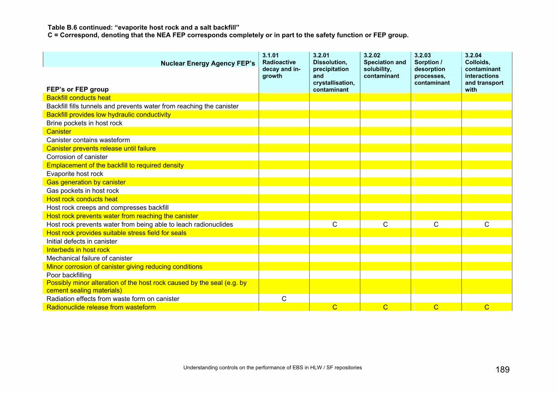
Understanding controls on the performance of EBS in HLW / SF repositories 189
Table B.6 continued: “evaporite host rock and a salt backfill” C = Correspond, denoting that the NEA FEP corresponds completely or in part to the safety function or FEP group.
Nuclear Energy Agency FEP’s
FEP’s or FEP group
3.1.01 Radioactive decay and in-growth
3.2.01 Dissolution, precipitation and crystallisation, contaminant
3.2.02 Speciation and solubility, contaminant
3.2.03 Sorption / desorption processes, contaminant
3.2.04 Colloids, contaminant interactions and transport with
Backfill conducts heat Backfill fills tunnels and prevents water from reaching the canister Backfill provides low hydraulic conductivity Brine pockets in host rock Canister Canister contains wasteform Canister prevents release until failure Corrosion of canister Emplacement of the backfill to required density Evaporite host rock Gas generation by canister Gas pockets in host rock Host rock conducts heat Host rock creeps and compresses backfill Host rock prevents water from reaching the canister Host rock prevents water from being able to leach radionuclides C C C C Host rock provides suitable stress field for seals Initial defects in canister Interbeds in host rock Mechanical failure of canister Minor corrosion of canister giving reducing conditions Poor backfilling Possibly minor alteration of the host rock caused by the seal (e.g. by cement sealing materials) Radiation effects from waste form on canister C Radionuclide release from wasteform C C C C

Understanding controls on the performance of EBS in HLW / SF repositories 190
Nuclear Energy Agency FEP’s
FEP’s or FEP group
3.1.01 Radioactive decay and in-growth
3.2.01 Dissolution, precipitation and crystallisation, contaminant
3.2.02 Speciation and solubility, contaminant
3.2.03 Sorption / desorption processes, contaminant
3.2.04 Colloids, contaminant interactions and transport with
Salt backfill Seals Seal anchoring strength and degradation Seal essentially prevents water from reaching the canister Seals prevent access Seals prevent water flow Seal properties and degradation Seals provide low hydraulic conductivity Seals provide mechanical support for backfill Slow dissolution of waste form and release of radionuclides C C C C Stability of HLW glass in brine Unexpected ‘poor ground conditions’ Thermo-hydro-mechanical behaviour of the backfill driven by heat from the canister Wasteform Water inflow to canister Does the NEA FEP correspond to at least one safety function / FEP group? Yes Yes Yes Yes Yes
Table B.6 continued: “evaporite host rock and a salt backfill” C = Correspond, denoting that the NEA FEP corresponds completely or in part to the safety function or FEP group.

Understanding controls on the performance of EBS in HLW / SF repositories 191
Table B.6 continued: “evaporite host rock and a salt backfill” C = Correspond, denoting that the NEA FEP corresponds completely or in part to the safety function or FEP group.
Nuclear Energy Agency FEP’s
FEP’s or FEP group
3.2.05 Chemical / complexing agents, effects on contaminant speciation / transport
3.2.06 Microbial / biological / plant-mediated processes, contaminant
3.2.07 Water-mediated transport of contaminants
Does the safety function or FEP group correspond to at least one NEA FEP?
Backfill conducts heat Yes Backfill fills tunnels and prevents water from reaching the canister Yes Backfill provides low hydraulic conductivity C Yes Brine pockets in host rock Yes Canister Yes Canister contains wasteform Yes Canister prevents release until failure Yes Corrosion of canister Yes Emplacement of the backfill to required density Yes Evaporite host rock Yes Gas generation by canister Yes Gas pockets in host rock Yes Host rock conducts heat Yes Host rock creeps and compresses backfill Yes Host rock prevents water from reaching the canister Yes Host rock prevents water from being able to leach radionuclides C C C Yes Host rock provides suitable stress field for seals Yes Initial defects in canister Yes Interbeds in host rock Yes Mechanical failure of canister Yes Minor corrosion of canister giving reducing conditions Yes Poor backfilling Yes Possibly minor alteration of the host rock caused by the seal (e.g. by cement sealing materials) Yes Radiation effects from waste form on canister Yes Radionuclide release from wasteform C C Yes

Understanding controls on the performance of EBS in HLW / SF repositories 192
Nuclear Energy Agency FEP’s
FEP’s or FEP group
3.2.05 Chemical / complexing agents, effects on contaminant speciation / transport
3.2.06 Microbial / biological / plant-mediated processes, contaminant
3.2.07 Water-mediated transport of contaminants
Does the safety function or FEP group correspond to at least one NEA FEP?
Salt backfill Yes Seals Yes Seal anchoring strength and degradation Yes Seal essentially prevents water from reaching the canister Yes Seals prevent access Yes Seals prevent water flow Yes Seal properties and degradation Yes Seals provide low hydraulic conductivity Yes Seals provide mechanical support for backfill Yes Slow dissolution of waste form and release of radionuclides C C Yes Stability of HLW glass in brine Yes Unexpected ‘poor ground conditions’ Yes Thermo-hydro-mechanical behaviour of the backfill driven by heat from the canister Yes Wasteform Yes Water inflow to canister Does the NEA FEP correspond to at least one safety function / FEP group? Yes Yes Yes
Table B.6 continued: “evaporite host rock and a salt backfill” C = Correspond, denoting that the NEA FEP corresponds completely or in part to the safety function or FEP group.

Appendix C Selection of representative radionuclides To ensure that the complexity of the calculations is minimized it is desirable to consider only a subset of radionuclides that occur in waste. However, the chosen radionuclides in the subset should have properties that adequately cover the full range of properties exhibited by all the radionuclides present in the inventory.
To select suitable nuclides for the calculations, all the nuclides present in the 2007 UK HLW inventory (Defra and NDA, 2008) were evaluated (Table A5). Those nuclides with shorter half-lives than 10 years were screened from further consideration. These nuclides would clearly exist at significant levels in the barriers beyond the waste formonly as a result of in-growth, which is not considered directly. Indeed, only nuclides with half-lives much in excess of 10 years would be transported in large proportions between barrier components. However, for illustrative purposes, it was considered desirable to include at least one nuclide with such a short half-life.
The remaining nuclides were then sorted in order of their half-lives. Groups of nuclides with half-lives with a similar order of magnitude were sorted in order of abundance in the waste. The most abundant nuclide from each group was selected for consideration in the calculations. Additionally, all non-sorbing nuclides were selected.
The resulting list of nuclides:
• H-3, half-life 12.3 years;
• Cs-137, half-life 30 years;
• Am-241, half-life 433 years;
• C-14, half-life 5,730 years;
• Pu-239, half-life 24,100 years;
• Cl-36, half-life 302,000 years;
• Tc-99, half-life 213,000 years;
• Zr-93, half-life 1,530,000 years;
• Np-237, half-life 2,140,000 years;
• I-129, half-life 15,700,000 years; and
• U-235, half-life 704,000,000 years
The chemical properties of these nuclides were compared with the properties of other nuclides in the inventory (Table C5). It is stressed that a complete review of radionuclide chemistry is outside the scope of this project, and only sufficient information to support the selection of nuclides for consideration in the calculations was assembled. This information came from: Stenhouse (1996), Bradbury and Baeyens (2003), Bradbury et al. (2005), Nirex (2003, 2006), and Wang et al. (2006).
It was confirmed that the major properties of the selected radionuclides adequately covered the range of properties of the full inventory. Notably:
• sorption characteristics;
193 Understanding controls on the performance of EBS in HLW / SF repositories

Understanding controls on the performance of EBS in HLW / SF repositories 194
Detailed properties of each nuclide are unique. However, based on the behaviour of the nuclides in the above list it would be possible to deduce qualitatively the expected behaviours of other radionulides in the inventory, for example U238.
• chemical complexation expected in aqueous solutions.
• pH-dependence of chemical speciation;
• redox-sensitivity of chemical speciation;

Table C.1 Summary of characteristics of radionuclides in the 2007 UK HLW inventory (Defra and NDA, 2008). Entries corresponding to radionuclides with half-lives having a similar order are shown with the same coloured shading.
Nuclide Half-life Activity at 1.4.2007
% activity
Half-life
order Sorption likely
significant?
Redox-sensitivity possible under likely repository conditions
(with most likely valence, most oxidized forms
likely during operational and immediate post-
closure phases)?
Likely most abundant aqueous species
(after post-closure return to reducing conditions,
only most reduced species will be present)
Comment
Years TBq
U-238 4.47E+09 2.6E-2 3.63E-8 9 Yes - stronger for U(IV) than U(VI) Yes (+4, +6)
U(OH)4(aq), UO2(OH)2(aq), UO2(CO3)2
2- and UO2(CO3)3
4-
Not considered since decay will not be significant over
considered timeframe and other properties the same
as U235
U-235 7.04E+08 9.30E-04 1.30E-09 8 Yes - stronger for U(IV) than U(VI) Yes (+4, +6)
U(OH)4(aq), UO2(OH)2(aq), UO2(CO3)2
2- and UO2(CO3)3
4-
I-129 1.57E+07 8.60E-02 1.20E-07 7
No (though weakly sorbing on some
oxides and clays and possibly strongly sorbing on some
sulphide minerals)
No (most likely -1, possibly +5 in aerobic phase) I-, (possibly IO3
- if oxidizing)
U-236 2.34E+07 6.00E-03 8.38E-09 7 Yes - stronger for U(IV) than U(VI) Yes (+4, +6) U(OH)4(aq), UO2(OH)2(aq)
and UO2(CO3)22-
Pb-205 1.52E+07 4.20E-07 5.87E-13 7 Yes - strong Yes (+2, +4) Pb2+, Pb(OH)3-, Pb(OH)2
0, Pb(OH)+, carbonate
Nb-92 3.50E+07 8.90E-10 1.24E-15 7 Yes- strong No (+5 only) Nb(OH)50, Nb(OH)6
-
Strong tendency to hydrolyse
Zr-93 1.53E+06 5.50E+02 7.69E-04 6 Yes - strong No (+4 only) Zr(OH)3+, Zr(OH)2
2+, Zr(OH)5
-
Strong tendency to hydrolyse
Cs-135 2.30E+06 1.80E+02 2.52E-04 6 Yes No (+1 only) Cs+
Pd-107 6.50E+06 2.80E+01 3.91E-05 6 Yes (little data, by analogy with Co, Ni,
Yes (+2, +4, though +2 most likely)
Pd(OH)20, other hydroxy
complexes Strong tendency to
hydrolyse
Understanding controls on the performance of EBS in HLW / SF repositories 195

Nuclide Half-life Activity at 1.4.2007
% activity
Half-life
order Sorption likely
significant?
Redox-sensitivity possible under likely repository conditions
(with most likely valence, most oxidized forms
likely during operational and immediate post-
closure phases)?
Likely most abundant aqueous species
(after post-closure return to reducing conditions,
only most reduced species will be present)
Comment
Cd and Pb)
Np-237 2.14E+06 2.80E+01 3.91E-05 6 Yes - stronger for Np(IV) than for Np(V) Yes (+4, +5) Np4+, Np(OH)3
+, Np(OH)22+,
NpO2(OH)0, carbonate
Be-10 1.60E+06 3.70E-02 5.17E-08 6 Yes - possibly (though no data) No (+2 only) chlorides, sulphates, Be2+,
Be(H2O)42+, Be(OH)4
2-
Experimental sorption data lacking, likely similar
to other alkaline earths (e.g. Mg, Ca)
Mn-53 3.70E+06 1.10E-07 1.54E-13 6 Yes Yes (+2, +4, +7) Tc-97 2.60E+06 7.70E-09 1.08E-14 6 Yes - weak to strong Yes (+4, +7) TcO(OH)2(aq)
Hf-182 8.99E+06 1.80E-10 2.52E-16 6 Yes No (+4 only) Hf4+
Sn(IV) is an analogue. Similar behaviour to Zr
Bi-210m 3.00E+06 1.00E-11 1.40E-17 6 Tc-99 2.13E+05 2.40E+03 3.35E-03 5 Yes - weak to strong Yes (+4, +7) TcO(OH)2(aq)
Sn-126 1.00E+05 2.10E+02 2.93E-04 5 Yes -strong Yes (+2, +4) Sn(OH)4, Sn(OH)5-,
Sn(OH)62-
Cl-36 3.02E+05 1.30E+00 1.82E-06 5 No No (-1 only) Cl-
Pu-242 3.74E+05 7.90E-01 1.10E-06 5 Yes Yes (+3, +4, +5, +6 possible, +4 most likely)
Pu(SO4)+, Pu4+, PuO2+,
PuO22+, Pu(OH)3+,
Pu(OH)22+,, Pu(OH)4,
PuO2(OH)0
Ca-41 1.03E+05 1.10E-01 1.54E-07 5 Yes (variable) No (+2 only) Sr2+
U-234 2.46E+05 5.90E-02 8.24E-08 5 Yes - stronger for U(IV) than U(VI) Yes (+4, +6)
U(OH)4(aq), UO2(OH)2(aq), UO2(CO3)2
2- and UO2(CO3)3
4-
U-233 1.59E+05 8.60E-04 1.20E-09 5 Yes - stronger for U(IV) than U(VI) Yes (+4, +6)
U(OH)4(aq), UO2(OH)2(aq), UO2(CO3)2
2- and UO2(CO3)3
4-
Cm-248 3.40E+05 2.90E-05 4.05E-11 5 Yes (little data, Am is analogue) No (+3 only) Cm3+, hydrolysed species (by
analogy with Am)
Understanding controls on the performance of EBS in HLW / SF repositories 196

Nuclide Half-life Activity at 1.4.2007
% activity
Half-life
order Sorption likely
significant?
Redox-sensitivity possible under likely repository conditions
(with most likely valence, most oxidized forms
likely during operational and immediate post-
closure phases)?
Likely most abundant aqueous species
(after post-closure return to reducing conditions,
only most reduced species will be present)
Comment
Pu-239 2.41E+04 2.40E+02 3.35E-04 4 Yes Yes (+3, +4, +5, +6 possible, +4 most likely)
Pu(SO4)+, Pu4+, PuO2+,
PuO22+, Pu(OH)3+,
Pu(OH)22+,, Pu(OH)4,
PuO2(OH)0
Se-79 6.50E+04 9.50E+01 1.33E-04 4 Yes (redox-dependent) Yes (+2, +4, +6) SeO4
2-, SeO32-, Se2-
Ni-59 7.49E+04 2.90E+00 4.05E-06 4 Yes - weak to strong No (+2 only) Carbonate and sulphate, Ni2+, Ni(OH)+, Ni(OH)2
0
Nb-94 2.03E+04 1.60E-01 2.24E-07 4 Yes- strong No (+5 only) Nb(OH)50, Nb(OH)6
-
Th-230 7.54E+04 5.20E-02 7.27E-08 4 Yes - weak to strong No (+4 only) Th4+, Th(OH)3+, Th(OH)2
2+, Th(OH)4
0
Pa-231 3.28E+04 6.50E-03 9.08E-09 4 Yes (but data limited) Possibly (+4, +5, but +5 probably dominant) Pa(OH)4
0, Pa(OH)50
La-137 6.00E+04 4.30E-04 6.01E-10 4
Am-243 7.36E+03 1.40E+03 1.96E-03 3 Yes - strong No (+3 expected to
dominate, but +4 and +5 also occur)
Am3+, Am(OH)2+, Am(OH)2+
Pu-240 6.56E+03 4.10E+02 5.73E-04 3 Yes Yes (+3, +4, +5, +6 possible, +4 most likely)
Pu(SO4)+, Pu4+, PuO2+,
PuO22+, Pu(OH)3+,
Pu(OH)22+,, Pu(OH)4,
PuO2(OH)0
Cm-245 8.50E+03 1.80E+01 2.52E-05 3 Yes (little data, Am is analogue) No (+3 only) Cm3+, hydrolysed species (by
analogy with Am)
C-14 5.73E+03 1.30E+01 1.82E-05 3 No (though weakly sorbing) Yes (-4, +4) H2CO3
0, HCO3-,CO3
2-
Cm-246 4.73E+03 3.70E+00 5.17E-06 3 Yes (little data, Am is analogue) No (+3 only) Cm3+, hydrolysed species (by
analogy with Am)
Mo-93 3.50E+03 1.80E-01 2.52E-07 3 No - weak only No (+6 only) MoO42−
Ho-166m 1.20E+03 7.60E-02 1.06E-07 3 Yes (little data, Am is analogue) No (+3 only) Ho3+, Ho(OH)3
Understanding controls on the performance of EBS in HLW / SF repositories 197

Nuclide Half-life Activity at 1.4.2007
% activity
Half-life
order Sorption likely
significant?
Redox-sensitivity possible under likely repository conditions
(with most likely valence, most oxidized forms
likely during operational and immediate post-
closure phases)?
Likely most abundant aqueous species
(after post-closure return to reducing conditions,
only most reduced species will be present)
Comment
Ra-226 1.60E+03 3.50E-04 4.89E-10 3 Yes - weak to strong No (+2 only) Ra2+, also chloride, phosphate, sulphate
Th-229 7.34E+03 1.40E-05 1.96E-11 3 Yes - weak to strong No (+4 only) Th4+, Th(OH)3+, Th(OH)2
2+, Th(OH)4
0
Ho-163 4.57E+03 7.60E-06 1.06E-11 3 Yes (little data, Am is analogue) No (+3 only) Ho3+, Ho(OH)3
Am-241 4.33E+02 3.00E+05 4.19E-01 2 Yes - strong No (+3 expected to
dominate, but +4 and +5 also occur)
Am3+, Am(OH)2+, Am(OH)2+
Am-242m 1.41E+02 9.40E+02 1.31E-03 2 Yes - strong No (+3 expected to
dominate, but +4 and +5 also occur)
Am3+, Am(OH)2+, Am(OH)2+
Ni-63 1.00E+02 3.30E+02 4.61E-04 2 Yes - weak to strong No (+2 only) Carbonate and sulphate, Ni2+, Ni(OH)+, Ni(OH)2
0
Ag-108m 4.18E+02 2.40E-03 3.35E-09 2
No (but this is a conservative
assumption since no reliable data)
Yes (+1, +2, +3, most likely +1) Choride complexes
Cf-249 3.51E+02 2.30E-04 3.21E-10 2 Cf-251 8.98E+02 1.00E-05 1.40E-11 2 Nb91 6.80E+02 3.90E-12 5.45E-18 2 Yes- strong No (+5 only) Nb(OH)5
0, Nb(OH)6-
Cs-
137/Ba137-m
3.00E+01 4.10E+07 5.73E+01 1 Yes No (+1 only) Cs+
Sr-90/Y-90 2.91E+01 3.00E+07 4.19E+01 1 Yes (variable) No (+2 only) Sr2+
Sm-151 8.87E+01 1.20E+05 1.68E-01 1 Yes (little data, Am is analogue) No (+3 only) Pm3+, Pm(OH)3
Cm-244 1.81E+01 1.00E+05 1.40E-01 1 Yes (little data, Am is analogue) No (+3 only) Cm3+, hydrolysed species (by
analogy with Am)
Pu-241 1.44E+01 2.40E+04 3.35E-02 1 Yes Yes (+3, +4, +5, +6 Pu(SO4)+, Pu4+, PuO2+,
Understanding controls on the performance of EBS in HLW / SF repositories 198

Understanding controls on the performance of EBS in HLW / SF repositories 199
Nuclide Half-life Activity at 1.4.2007
% activity
Half-life
order Sorption likely
significant?
Redox-sensitivity possible under likely repository conditions
(with most likely valence, most oxidized forms
likely during operational and immediate post-
closure phases)?
Likely most abundant aqueous species
(after post-closure return to reducing conditions,
only most reduced species will be present)
Comment
possible, +4 most likely) PuO22+, Pu(OH)3+,
Pu(OH)22+,, Pu(OH)4,
PuO2(OH)0
Sn-121m 5.00E+01 4.90E+03 6.85E-03 1 Yes -strong Yes (+2, +4) Sn(OH)4, Sn(OH)5-,
Sn(OH)62-
Cd-113m 1.41E+01 2.50E+03 3.49E-03 1 No if significant Cl, possibly otherwise No (+2 only) Cd2+, Cd(OH)2, Strong
chloro-complexes
Eu-152 1.33E+01 1.20E+03 1.68E-03 1 Yes No (+3 only) Eu3+, Eu(OH)2+, Eu(OH)2+,
Eu(OH)30, Eu(OH)-
4
Cm-243 3.00E+01 1.10E+03 1.54E-03 1 Yes (little data, Am is analogue) No (+3 only) Cm3+, hydrolysed species (by
analogy with Am)
Pu-238 8.77E+01 9.00E+02 1.26E-03 1 Yes Yes (+3, +4, +5, +6 possible, +4 most likely)
Pu(SO4)+, Pu4+, PuO2+,
PuO22+, Pu(OH)3+,
Pu(OH)22+,, Pu(OH)4,
PuO2(OH)0
Nb-93m 1.64E+01 2.90E+02 4.05E-04 1 Yes- strong No (+5 only) Nb(OH)50, Nb(OH)6
-
H-3 1.23E+01 2.20E+02 3.07E-04 1 No No H2O
Pm-145 1.77E+01 2.00E-02 2.79E-08 1 Yes (little data, Am is analogue) Yes (+2, +3 most likely) Sm2+, Sm3+, Sm(OH)3
Ac-227 2.18E+01 2.60E-03 3.63E-09 1 Yes (little data, Am is analogue) No (+3 only) Ac3+, hydrolysed species (by
analogy with Am)
Cf-250 1.31E+01 8.40E-04 1.17E-09 1
U-232 6.98E+01 5.40E-04 7.55E-10 1 Yes - stronger for U(IV) than U(VI) Yes (+4, +6)
U(OH)4(aq), UO2(OH)2(aq), UO2(CO3)2
2- and UO2(CO3)3
4-
Pb-210 2.23E+01 8.60E-05 1.20E-10 1 Yes - strong Yes (+2, +4) Pb2+, Pb(OH)3-, Pb(OH)2
0, Pb(OH)+, carbonate

Appendix C References BRADBURY, M.H., BAEYENS, B., GECKEIS, H. AND RABUNG, Th. 2005. Sorption of Eu(III)/Cm(III) on Ca-montmorillonite and Na-illite. Part 2: Surface complexation modelling. Geochimica et Cosmochimica Acta, 69, 5403-5412.
BRADBURY, M.H., BAEYENS, B. 2003. Far field sorption data bases for Performance Assessment of a high-level radioactive waste repository in an undisturbed Opalinus Clay host rock. PSI Report 03-08/NAGRA Report NTB-02-19. 138pp.
DEFRA and NDA, 2008. The 2007 UK Radioactive Waste Inventory Main Report. Defra Report Defra/RAS/08.002; NDA Report NDA/RWMD/004. 131pp.
NIREX, 2006. Near field sensitivity studies of a reference repository concept for UK high-level waste/spent fuel. Nirex Technical Note 510115. United Kingdom Nirex Limited, Harwell. 56pp.
NIREX, 2003. Analysis and interpretation of geosphere sorption data for a performance assessment. Nirex Report N/083, UK. Nirex Limited, Harwell, 122pp.
STENHOUSE, M.J. 1996. Sorption databases for crystalline, marl and bentonite for Performance Assessment. Nagra Technical Report NTB 93-06. Nagra, Wettingen, Switzerland. 107pp.
WANG, X., XUA, D., CHENB, L., TANA, X., ZHOU, X., RENA, A. AND CHENA, Ch. 2006. Sorption and complexation of Eu(III) on alumina: Effects of pH, ionic strength, humic acid and chelating resin on kinetic dissociation study. Applied Radiation and Isotopes, 64, 414-442.
Understanding controls on the performance of EBS in HLW / SF repositories 200

We are The Environment Agency. It's our job to look after your environment and make it a better place – for you, and for future generations.
Your environment is the air you breathe, the water you drink and the ground you walk on. Working with business, Government and society as a whole, we are making your environment cleaner and healthier.
The Environment Agency. Out there, making your environment a better place.
Published by: Environment Agency Rio House Waterside Drive, Aztec West Almondsbury, Bristol BS32 4UD Tel: 0870 8506506 Email: [email protected] www.environment-agency.gov.uk © Environment Agency All rights reserved. This document may be reproduced with prior permission of the Environment Agency.