Embed Size (px)
Citation preview
Underpinning and Foundation Refurbishment Techniques Procedures, Design and Safety Requirements
EXTENDED ABSTRACT
Manuel João Niza das Neves
Júri
Presidente: Prof. Doutor José Manuel Matos Noronha da Camara
Orientador: Prof. Alexandre da Luz Pinto
Vogal: Prof. Doutor Victor Manuel Pissarra Cavaleiro
October 2010

1
Underpinning and Foundation Refurbishment Techniques
Procedures, Design and Safety Requirements
EXTENDED ABSTRACT
1. Introduction
The safeguard of the built heritage has been gaining an increased importance among the
various entities related to construction. Nevertheless, the shift of paradigm that needs to take
place in order to achieve an overlap of new construction by rehabilitation/reuse of buildings is
still far from being established in contemporary society.
However, there are a few construction techniques, which have been successfully implemented
for several years, that enable the execution of temporary and definitive works, namely
excavations in urban areas and underpinning, in an economical, practical and, above all, safe
manner. The growing number of projects of this nature was not accompanied by the
development of standards and codes of practice specifically dedicated to this subject. As a
result, it is often required from engineers to thoughtfully adapt the existing regulations, applied
to new construction, to the project at hand.
This paper, whose main objective is to review/overview some of the construction techniques
associated with underpinning operations and the systematization of the needed steps applicable
to two procedures in particular (micropiles and jet grouting), aims to incorporate, in a single
document, the most important features and the safety requirements involved in these projects.
Finally, three case studies of underpinning are presented, concerning the application of the
stated techniques, design by the company JetSJ Geotecnia, Lda, between March and
September of 2010.
2. Underpinning project and construction techniques
The rehabilitation of an existing building, mostly 40 to 50 years old, motivated by a change of
use or structural damage, which may be a consequence of insufficient soil bearing capacity,
may require an underpinning project.
This type of work requires skilled labour, not only constructors, but also in the planning stage,
since there is not an universal solution applicable to all cases. In fact, the underpinning solution
depends on many factors, among which are the mechanical properties of the support stratum of
soil, the conservation conditions of the foundation elements and, above all, the restrictions
imposed during this operation.
The need for reinforcement of foundations is generally associated with works under an existing
construction or in their immediate proximity (changes in boundary conditions of the ground
foundation), or induced by the degradation with time of the foundation stratum. The first case is
becoming increasingly common in urban areas, due to the need of mobility, resulting in the
execution of tunnels or underpasses, but also the creation of underground car parks, associated
with the construction of several levels of basements.
2
It is possible to intervene in various manners in order to reinforce/underpin foundations. One
possibility is to improve the soil mechanical properties, increasing its bearing capacity and its
stiffness. On the other hand, it is also possible to act on the foundation itself, improving its
resistance or reducing the foundation-soil contact stresses.
2.1. Micropiles
Micropiles are presented as a variant of deep foundations, and consist of piles of small diameter
between 75mm and 350mm, cast in situ, vertical or executed with an angle. These elements,
when compressed, transmit their forces to the ground primarily by lateral friction (floating piles),
although there is a small contribution from the bearing resistance. In general, the execution of
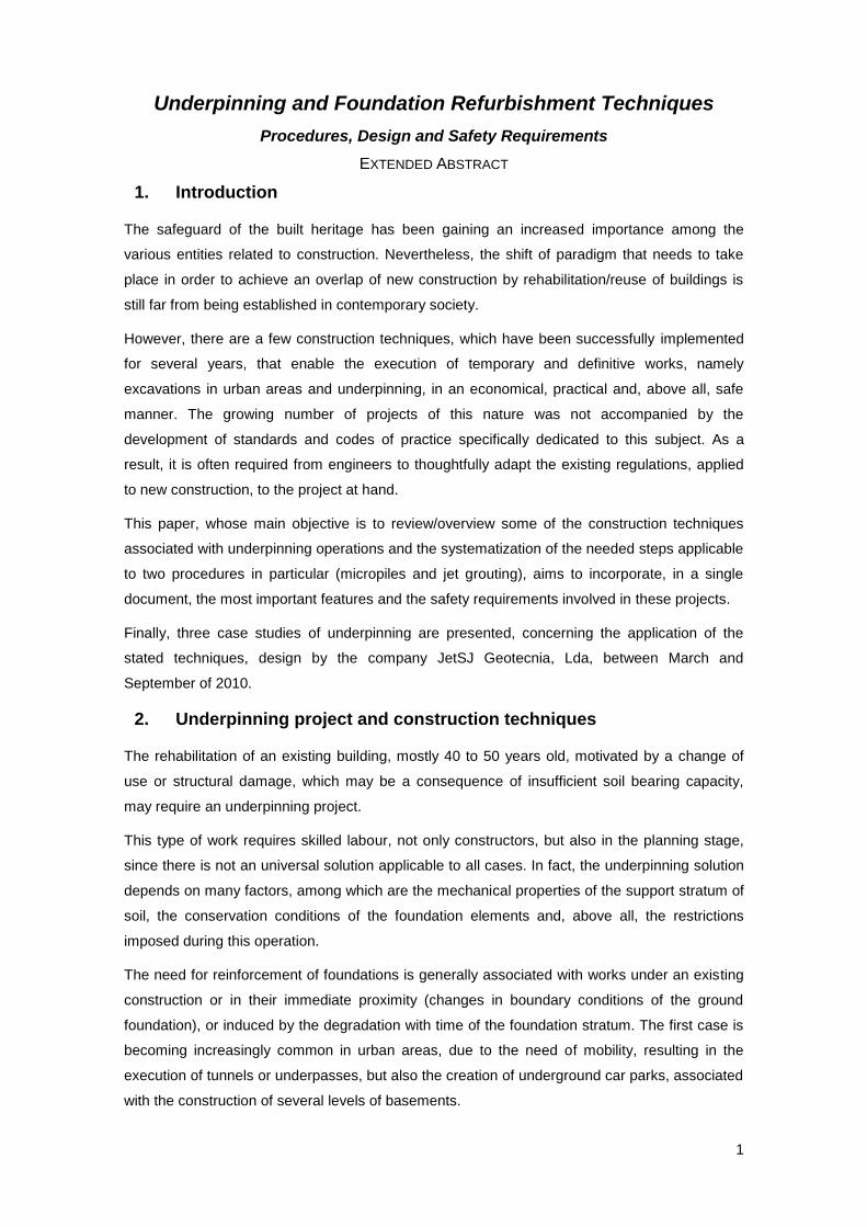
micropiles is divided into the following stages [1], as illustrated in Figure 1:
Drilling to the specified depth;
Placement of the reinforcement;
Gravity fill injection of grout;
Pressure postgrouting injection, when applicable.
FIGURE 1. TYPICAL MICROPILE CONSTRUCTION SEQUENCE [1].
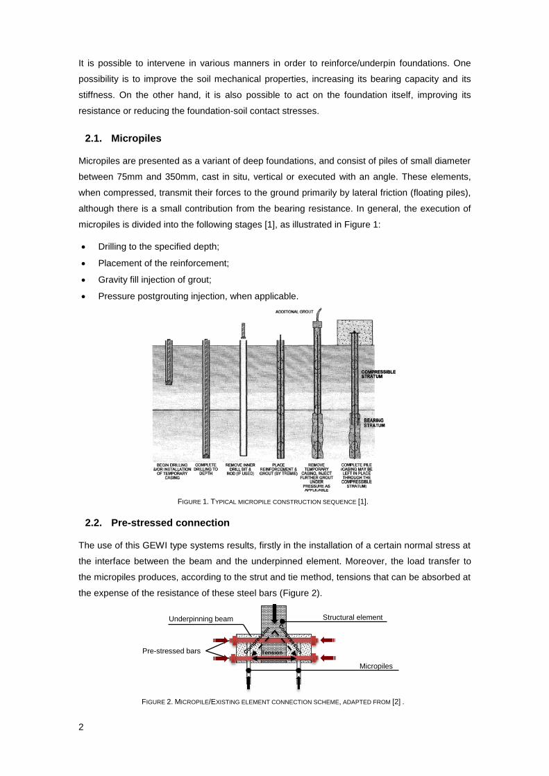
2.2. Pre-stressed connection
The use of this GEWI type systems results, firstly in the installation of a certain normal stress at
the interface between the beam and the underpinned element. Moreover, the load transfer to
the micropiles produces, according to the strut and tie method, tensions that can be absorbed at
the expense of the resistance of these steel bars (Figure 2).
FIGURE 2. MICROPILE/EXISTING ELEMENT CONNECTION SCHEME, ADAPTED FROM [2] .
Underpinning beam Structural element
Pre-stressed bars
Micropiles
Tension
3
2.3. Jet grouting
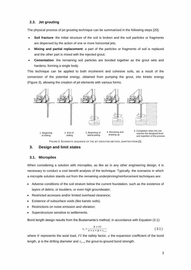
The physical process of jet grouting technique can be summarized in the following steps [20]:
Soil fracture: the initial structure of the soil is broken and the soil particles or fragments
are dispersed by the action of one or more horizontal jets;
Mixing and partial replacement: a part of the particles or fragments of soil is replaced
and the other part is mixed with the injected grout;
Cementation: the remaining soil particles are bonded together as the grout sets and
hardens, forming a single body.
This technique can be applied to both incoherent and cohesive soils, as a result of the
conversion of the potential energy, obtained from pumping the grout, into kinetic energy
(Figure 3), allowing the creation of jet elements with various forms.
FIGURE 3. SCHEMATIC SEQUENCE OF THE JET GROUTING METHOD, ADAPTED FROM [3].
3. Design and limit states
3.1. Micropiles
When considering a solution with micropiles, as like as in any other engineering design, it is
necessary to conduct a cost benefit analysis of the technique. Typically, the scenarios in which
a micropile solution stands out from the remaining underpinning/reinforcement techniques are:
Adverse conditions of the soil stratum below the current foundation, such as the existence of
layers of debris, or boulders, or even high groundwater;
Restricted accesses and/or limited overhead clearance;
Existence of subsurface voids (like karstic soils);
Restrictions on noise emission and vibration;
Superstructure sensitive to settlements.
Bond length design results from the Bustamante’s method, in accordance with Equation (3.1):
( 3.1 )
where represents the axial load, the safety factor, the expansion coefficient of the bond
length, is the drilling diameter and the grout-to-ground bond strength.
1. Beginning of drilling
2. End of drilling
3. Beginning of lateral jetting
4. Revolving and drawing up
5. Completion when the rod reaches the designed level and repetition of the process
4
When designing these elements the end bearing resistance is usually neglected. This decision
is justified by the reduced cross section of the tip of the micropile, but also due to the drilling
techniques used, that can result in an accumulation of debris on the bottom of the hole, difficult
to remove completely. The maximum axial compression that a micropile can be subjected to,
according to article § 6.7.3.2 (a) of the EC 4 [4] is expressed in Equation (3.2),
( 3.2 )
where represents the cross section of the steel hollow section and its yield stress, while
corresponds to the grout cross section and its design compressive strength. The last term
is related to the reinforcement bars inserted in the micropile, being and its cross section
and yield stress. However, the previous expression is only valid when the shear load is inferior
to half of the plastic shear resistance.
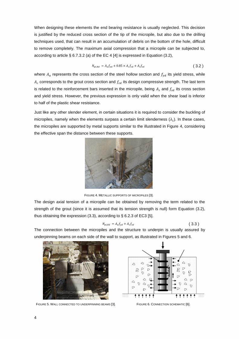
Just like any other slender element, in certain situations it is required to consider the buckling of
micropiles, namely when the elements surpass a certain limit slenderness ( ). In these cases,
the micropiles are supported by metal supports similar to the illustrated in Figure 4, considering
the effective span the distance between these supports.
FIGURE 4. METALLIC SUPPORTS OF MICROPILES [3].
The design axial tension of a micropile can be obtained by removing the term related to the
strength of the grout (since it is assumed that its tension strength is null) form Equation (3.2),
thus obtaining the expression (3.3), according to § 6.2.3 of EC3 [5].
( 3.3 )
The connection between the micropiles and the structure to underpin is usually assured by
underpinning beams on each side of the wall to support, as illustrated in Figures 5 and 6.
FIGURE 5. WALL CONNECTED TO UNDERPINNING BEAMS [3]. FIGURE 6. CONNECTION SCHEMATIC [6].
5
The serviceability limit state of micropiles is verified by evaluating the elastic vertical deflection
of the elements ( ), accordingly to Equations (3.4) and (3.5), and then comparing the obtained
value to the limits prescribed in Annex H of the EC7 [7].
( 3.4 )
( 3.5 )
Where is the axial load while and are the length and the axial stiffness of the micropile,
considering both the stiffness of the steel section ( ) and the grout ( ).
3.2. Jet grouting
Unlike the previous technique, where the material properties were entirely known, jet grouting
do not lead to accurate predictions of the final characteristics of the treated soil when in the
design stage. This situation is due to the fundamental concept of this technique, which is not to
replace completely the soil to be treated, but to improve its geomechanical characteristics by
adding grout. Therefore, the final product is strongly conditioned by the initial characteristics of
the soil, as well as its replacement percentage.
Typically, jet grouting solutions are profitable and stand out, in relation to other forms of
injection, in the following situations:
In heterogeneous soils, whose layers are well defined, resulting in an adjustment of the
parameters of the jet for each type of soil, obtaining a uniform treatment in depth;
When jet grouting columns have more than one purpose, such as excavations (common in
underpinning operations), where these elements prevent the entry of water into the work site,
as well as withstand the impulses of the soil and from other overloads;
In underpinning operations executed from the outside of buildings, that after the cure of the
material are perfectly bounded to the existing structure;
When there are noise and vibration restrictions.
To calculate the length of jet column ( ), the method of Bustamante is used, presented in
Equation (3.6):
( 3.6 )
where represents the axial load, safety factor, is the drilling diameter and the soil
cement-to-ground bond strength.
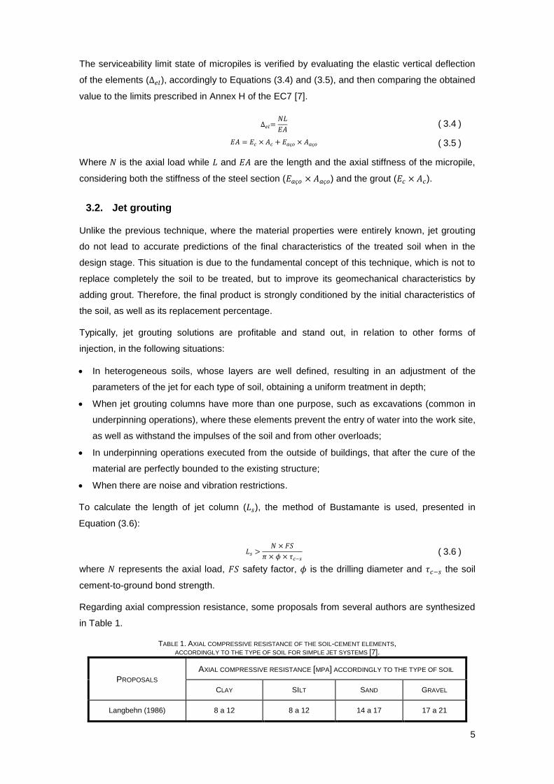
Regarding axial compression resistance, some proposals from several authors are synthesized
in Table 1.
TABLE 1. AXIAL COMPRESSIVE RESISTANCE OF THE SOIL-CEMENT ELEMENTS, ACCORDINGLY TO THE TYPE OF SOIL FOR SIMPLE JET SYSTEMS [7].
PROPOSALS
AXIAL COMPRESSIVE RESISTANCE [MPA] ACCORDINGLY TO THE TYPE OF SOIL
CLAY SILT SAND GRAVEL
Langbehn (1986) 8 a 12 8 a 12 14 a 17 17 a 21
6
Mosiici e Guatteri (1986) 2 6 12 -
Xanthakos et alli (1994) 4 a 7 4 a 7 7 a 14 10 a 17
Baumann et alli (1984) 3 a 10 3 a 10 5 a 14 6 a 18
Fiorotto (no date) 2 a 4 6 10 15
Given the high dispersion of resistance values presented it is usual, when in a design stage, to
specify a minimum compressive resistance, generally 2 MPa.
In situations where tensions are applied to the jet columns, the usual solution is to insert in to
them metallic elements, like micropiles, ignoring the tension resistance of the soil cement. In
these cases, the ultimate limit state of tension of the reinforcement element and the
geotechnical strength limit state between the reinforcement and the jet column should be
verified.
Regarding the verification of the serviceability limit state, the columns are treated as micropiles,
which means that the estimated vertical deflection of the elements ( ), calculated from
Equation (3.7), should be compared to the limits prescribed in Annex H of the EC7 [7]. In that
expression, is the axial load while and are the length and the axial stiffness of the jet
column.
( 3.7 )
An estimate of the stiffness module of the soil-cement columns can be obtained graphically,
which establishes a correspondence between de stiffness of the elements and their axial
compressive resistance (Figure 7).
FIGURE 7. WALL CONNECTED TO UNDERPINNING BEAMS [2].
From within the gathered research papers it was possible to conclude that the stiffness of jet
columns executed in incoherent soils is generally higher than when executed in cohesive soils.
Nevertheless, it is also clear that the curing also plays an important role in the final stiffness of
these elements.
(1) JJGA recomendation for all types of soils
(2) Lunardi, Mongilardi e Tornaghi, 1986 – fine and medium sands (Ródio – Italy)
(3) Paoli, et al, 1989 – peat soil (Ródio – Italy)
(4) Novatecna, 1994 – expansive silty clay for ultimate load
(5) Lunardi, Mongilardi e Tornaghi, 1986 – gravel with sand (Ródio – Italy)
(6) Novatecna, 1994 – expansive silty clay for 0.4 of the ultimate load
Axial compressive strength, qu (MPa)
Stifn
ess m
od
ulu
s E
(1
03 M
Pa
)
(fo
r 0
.4 q
u)
7
4. Case studies
4.1. Rosa Araújo Hotel
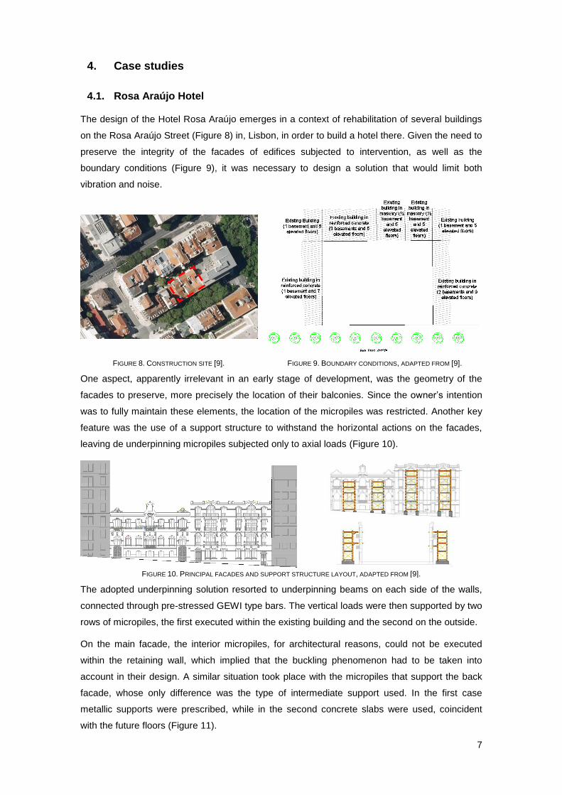
The design of the Hotel Rosa Araújo emerges in a context of rehabilitation of several buildings
on the Rosa Araújo Street (Figure 8) in, Lisbon, in order to build a hotel there. Given the need to
preserve the integrity of the facades of edifices subjected to intervention, as well as the
boundary conditions (Figure 9), it was necessary to design a solution that would limit both
vibration and noise.
FIGURE 8. CONSTRUCTION SITE [9]. FIGURE 9. BOUNDARY CONDITIONS, ADAPTED FROM [9].
One aspect, apparently irrelevant in an early stage of development, was the geometry of the
facades to preserve, more precisely the location of their balconies. Since the owner’s intention
was to fully maintain these elements, the location of the micropiles was restricted. Another key
feature was the use of a support structure to withstand the horizontal actions on the facades,
leaving de underpinning micropiles subjected only to axial loads (Figure 10).
FIGURE 10. PRINCIPAL FACADES AND SUPPORT STRUCTURE LAYOUT, ADAPTED FROM [9].
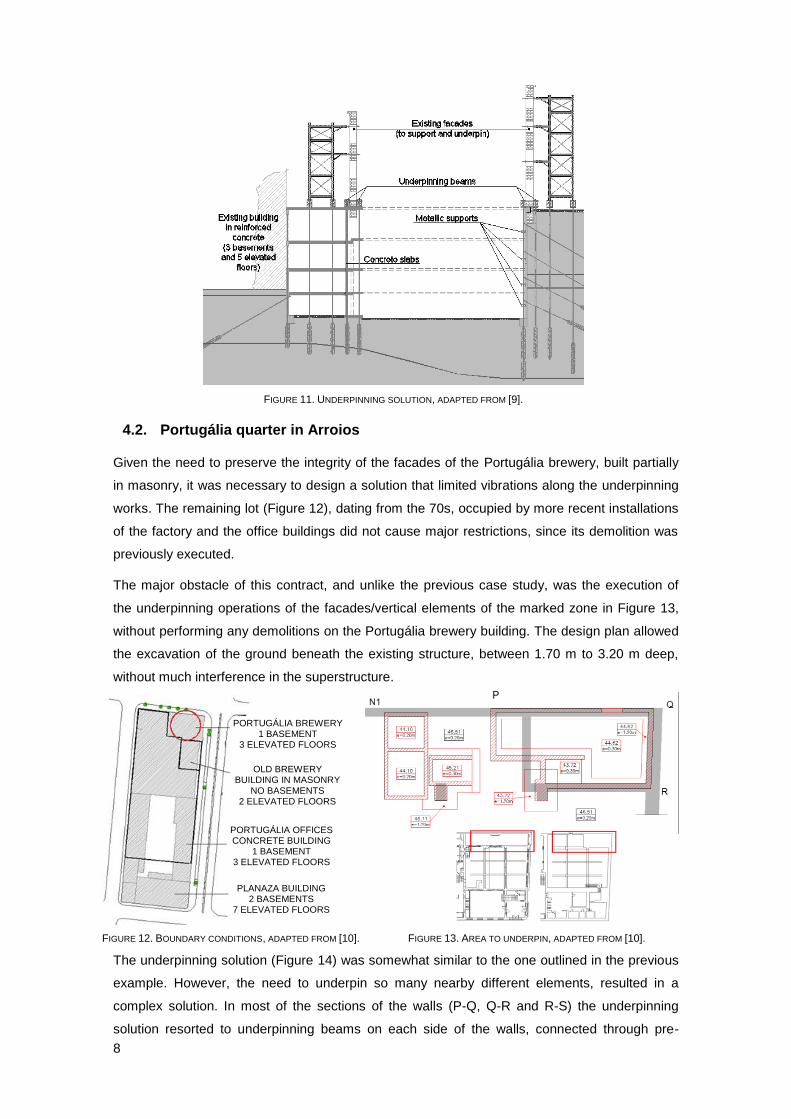
The adopted underpinning solution resorted to underpinning beams on each side of the walls,
connected through pre-stressed GEWI type bars. The vertical loads were then supported by two
rows of micropiles, the first executed within the existing building and the second on the outside.
On the main facade, the interior micropiles, for architectural reasons, could not be executed
within the retaining wall, which implied that the buckling phenomenon had to be taken into
account in their design. A similar situation took place with the micropiles that support the back
facade, whose only difference was the type of intermediate support used. In the first case
metallic supports were prescribed, while in the second concrete slabs were used, coincident
with the future floors (Figure 11).
8
FIGURE 11. UNDERPINNING SOLUTION, ADAPTED FROM [9].
4.2. Portugália quarter in Arroios
Given the need to preserve the integrity of the facades of the Portugália brewery, built partially
in masonry, it was necessary to design a solution that limited vibrations along the underpinning
works. The remaining lot (Figure 12), dating from the 70s, occupied by more recent installations
of the factory and the office buildings did not cause major restrictions, since its demolition was
previously executed.
The major obstacle of this contract, and unlike the previous case study, was the execution of
the underpinning operations of the facades/vertical elements of the marked zone in Figure 13,
without performing any demolitions on the Portugália brewery building. The design plan allowed
the excavation of the ground beneath the existing structure, between 1.70 m to 3.20 m deep,
without much interference in the superstructure.
FIGURE 12. BOUNDARY CONDITIONS, ADAPTED FROM [10]. FIGURE 13. AREA TO UNDERPIN, ADAPTED FROM [10].
The underpinning solution (Figure 14) was somewhat similar to the one outlined in the previous
example. However, the need to underpin so many nearby different elements, resulted in a
complex solution. In most of the sections of the walls (P-Q, Q-R and R-S) the underpinning
solution resorted to underpinning beams on each side of the walls, connected through pre-
PORTUGÁLIA BREWERY 1 BASEMENT
3 ELEVATED FLOORS
OLD BREWERY BUILDING IN MASONRY
NO BASEMENTS 2 ELEVATED FLOORS
PORTUGÁLIA OFFICES CONCRETE BUILDING
1 BASEMENT 3 ELEVATED FLOORS
PLANAZA BUILDING 2 BASEMENTS
7 ELEVATED FLOORS
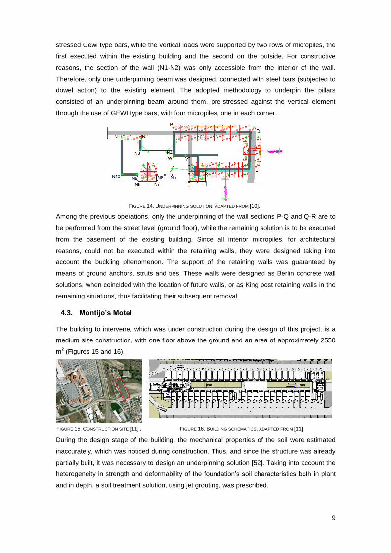
9
stressed Gewi type bars, while the vertical loads were supported by two rows of micropiles, the
first executed within the existing building and the second on the outside. For constructive
reasons, the section of the wall (N1-N2) was only accessible from the interior of the wall.
Therefore, only one underpinning beam was designed, connected with steel bars (subjected to
dowel action) to the existing element. The adopted methodology to underpin the pillars
consisted of an underpinning beam around them, pre-stressed against the vertical element
through the use of GEWI type bars, with four micropiles, one in each corner.
FIGURE 14. UNDERPINNING SOLUTION, ADAPTED FROM [10].
Among the previous operations, only the underpinning of the wall sections P-Q and Q-R are to
be performed from the street level (ground floor), while the remaining solution is to be executed
from the basement of the existing building. Since all interior micropiles, for architectural
reasons, could not be executed within the retaining walls, they were designed taking into
account the buckling phenomenon. The support of the retaining walls was guaranteed by
means of ground anchors, struts and ties. These walls were designed as Berlin concrete wall
solutions, when coincided with the location of future walls, or as King post retaining walls in the
remaining situations, thus facilitating their subsequent removal.
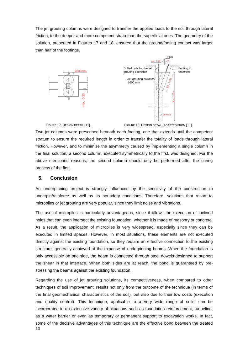
4.3. Montijo’s Motel
The building to intervene, which was under construction during the design of this project, is a
medium size construction, with one floor above the ground and an area of approximately 2550
m2 (Figures 15 and 16).
FIGURE 15. CONSTRUCTION SITE [11] . FIGURE 16. BUILDING SCHEMATICS, ADAPTED FROM [11].
During the design stage of the building, the mechanical properties of the soil were estimated
inaccurately, which was noticed during construction. Thus, and since the structure was already
partially built, it was necessary to design an underpinning solution [52]. Taking into account the
heterogeneity in strength and deformability of the foundation’s soil characteristics both in plant
and in depth, a soil treatment solution, using jet grouting, was prescribed.
10
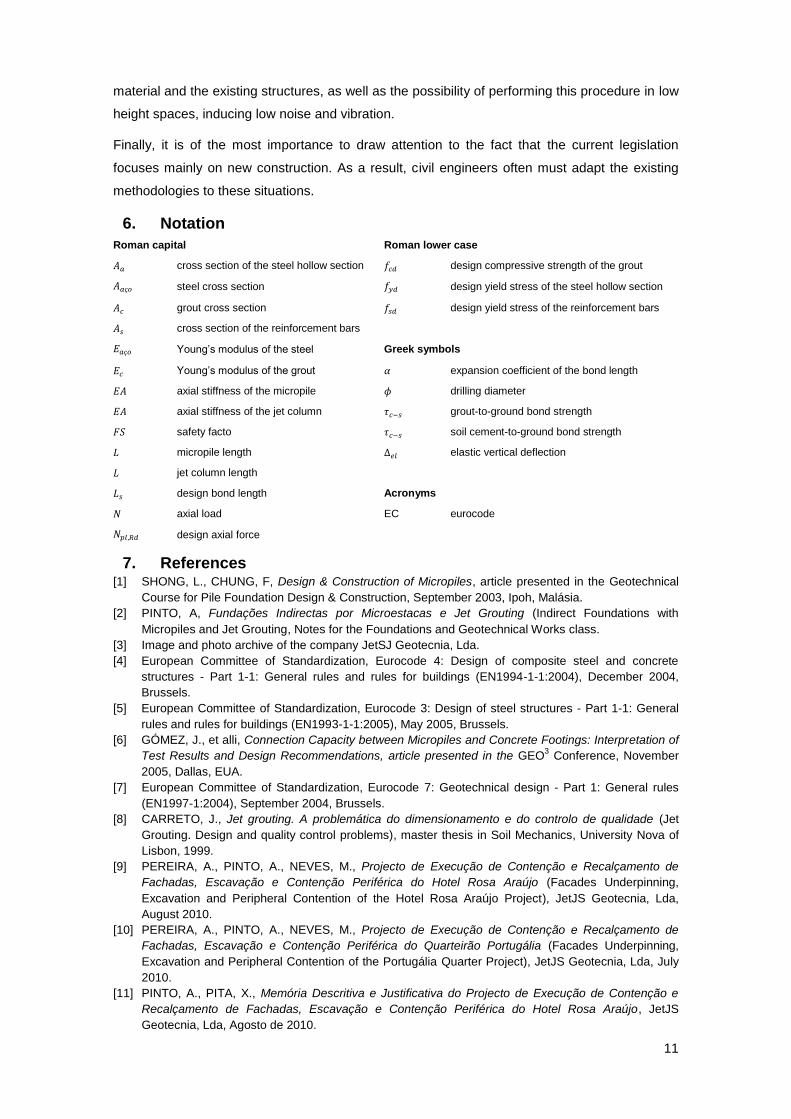
The jet grouting columns were designed to transfer the applied loads to the soil through lateral
friction, to the deeper and more competent strata than the superficial ones. The geometry of the
solution, presented in Figures 17 and 18, ensured that the ground/footing contact was larger
than half of the footings.
FIGURE 17. DESIGN DETAIL [11]. FIGURE 18. DESIGN DETAIL, ADAPTED FROM [11].
Two jet columns were prescribed beneath each footing, one that extends until the competent
stratum to ensure the required length in order to transfer the totality of loads through lateral
friction. However, and to minimize the asymmetry caused by implementing a single column in
the final solution, a second column, executed symmetrically to the first, was designed. For the
above mentioned reasons, the second column should only be performed after the curing
process of the first.
5. Conclusion
An underpinning project is strongly influenced by the sensitivity of the construction to
underpin/reinforce as well as its boundary conditions. Therefore, solutions that resort to
micropiles or jet grouting are very popular, since they limit noise and vibrations.
The use of micropiles is particularly advantageous, since it allows the execution of inclined
holes that can even intersect the existing foundation, whether it is made of masonry or concrete.
As a result, the application of micropiles is very widespread, especially since they can be
executed in limited spaces. However, in most situations, these elements are not executed
directly against the existing foundation, so they require an effective connection to the existing
structure, generally achieved at the expense of underpinning beams. When the foundation is
only accessible on one side, the beam is connected through steel dowels designed to support
the shear in that interface. When both sides are at reach, the bond is guaranteed by pre-
stressing the beams against the existing foundation.
Regarding the use of jet grouting solutions, its competitiveness, when compared to other
techniques of soil improvement, results not only from the outcome of the technique (in terms of
the final geomechanical characteristics of the soil), but also due to their low costs (execution
and quality control). This technique, applicable to a very wide range of soils, can be
incorporated in an extensive variety of situations such as foundation reinforcement, tunneling,
as a water barrier or even as temporary or permanent support to excavation works. In fact,
some of the decisive advantages of this technique are the effective bond between the treated
Pillar
Footing to underpin
Drilled hole for the jet grouting operation
Jet grouting columns
∅600 mm
11
material and the existing structures, as well as the possibility of performing this procedure in low
height spaces, inducing low noise and vibration.
Finally, it is of the most importance to draw attention to the fact that the current legislation
focuses mainly on new construction. As a result, civil engineers often must adapt the existing
methodologies to these situations.
6. Notation
Roman capital Roman lower case
cross section of the steel hollow section design compressive strength of the grout
steel cross section design yield stress of the steel hollow section
grout cross section design yield stress of the reinforcement bars
cross section of the reinforcement bars
Young’s modulus of the steel Greek symbols
Young’s modulus of the grout expansion coefficient of the bond length
axial stiffness of the micropile drilling diameter
axial stiffness of the jet column grout-to-ground bond strength
safety facto soil cement-to-ground bond strength
micropile length elastic vertical deflection
jet column length
design bond length Acronyms
axial load EC eurocode
design axial force
7. References [1] SHONG, L., CHUNG, F, Design & Construction of Micropiles, article presented in the Geotechnical
Course for Pile Foundation Design & Construction, September 2003, Ipoh, Malásia.
[2] PINTO, A, Fundações Indirectas por Microestacas e Jet Grouting (Indirect Foundations with
Micropiles and Jet Grouting, Notes for the Foundations and Geotechnical Works class.
[3] Image and photo archive of the company JetSJ Geotecnia, Lda.
[4] European Committee of Standardization, Eurocode 4: Design of composite steel and concrete
structures - Part 1-1: General rules and rules for buildings (EN1994-1-1:2004), December 2004,
Brussels.
[5] European Committee of Standardization, Eurocode 3: Design of steel structures - Part 1-1: General
rules and rules for buildings (EN1993-1-1:2005), May 2005, Brussels.
[6] GÓMEZ, J., et alli, Connection Capacity between Micropiles and Concrete Footings: Interpretation of
Test Results and Design Recommendations, article presented in the GEO3 Conference, November
2005, Dallas, EUA.
[7] European Committee of Standardization, Eurocode 7: Geotechnical design - Part 1: General rules
(EN1997-1:2004), September 2004, Brussels.
[8] CARRETO, J., Jet grouting. A problemática do dimensionamento e do controlo de qualidade (Jet
Grouting. Design and quality control problems), master thesis in Soil Mechanics, University Nova of
Lisbon, 1999.
[9] PEREIRA, A., PINTO, A., NEVES, M., Projecto de Execução de Contenção e Recalçamento de
Fachadas, Escavação e Contenção Periférica do Hotel Rosa Araújo (Facades Underpinning,
Excavation and Peripheral Contention of the Hotel Rosa Araújo Project), JetJS Geotecnia, Lda,
August 2010.
[10] PEREIRA, A., PINTO, A., NEVES, M., Projecto de Execução de Contenção e Recalçamento de
Fachadas, Escavação e Contenção Periférica do Quarteirão Portugália (Facades Underpinning,
Excavation and Peripheral Contention of the Portugália Quarter Project), JetJS Geotecnia, Lda, July
2010.
[11] PINTO, A., PITA, X., Memória Descritiva e Justificativa do Projecto de Execução de Contenção e
Recalçamento de Fachadas, Escavação e Contenção Periférica do Hotel Rosa Araújo, JetJS
Geotecnia, Lda, Agosto de 2010.