Embed Size (px)
Citation preview
Underground eLearning
Longwall Course Catalog
4/12/2018 – Longwall eLearning Catalog Page 2 of 30
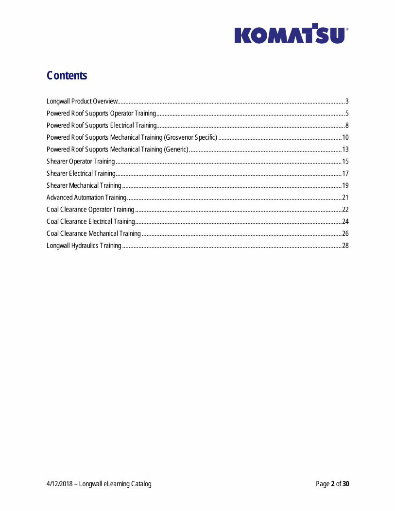
Contents
Longwall Product Overview ............................................................................................................................................ 3
Powered Roof Supports Operator Training .................................................................................................................... 5
Powered Roof Supports Electrical Training.................................................................................................................... 8
Powered Roof Supports Mechanical Training (Grosvenor Specific) ............................................................................ 10
Powered Roof Supports Mechanical Training (Generic) .............................................................................................. 13
Shearer Operator Training ........................................................................................................................................... 15
Shearer Electrical Training ........................................................................................................................................... 17
Shearer Mechanical Training ....................................................................................................................................... 19
Advanced Automation Training .................................................................................................................................... 21
Coal Clearance Operator Training ............................................................................................................................... 22
Coal Clearance Electrical Training ............................................................................................................................... 24
Coal Clearance Mechanical Training ........................................................................................................................... 26
Longwall Hydraulics Training ....................................................................................................................................... 28
4/12/2018 – Longwall eLearning Catalog Page 3 of 30
Longwall Product Overview
Description:
This is the Longwall Product Overview eLearning module. In this module, you will be given an overview of the operational, electrical, and mechanical topics for each of the major components on the Longwall system. These major components include the Powered Roof Supports, Shearer, and the Coal Clearance system.
Module Outline:
• Lesson 1.0 – Longwall System Integration • Lesson 1.1 - PRS Orientation • Lesson 1.2 - PRS Operational Overview • Lesson 1.3 - PRS Electrical Overview • Lesson 1.4 - PRS Mechanical Overview • Lesson 1.5 - Shearer Orientation • Lesson 1.6 - Shearer Operational Overview • Lesson 1.7 - Shearer Electrical Overview • Lesson 1.8 - Shearer Mechanical Overview • Lesson 1.9 - Coal Clearance Orientation • Lesson 1.10 - Coal Clearance Operational Overview • Lesson 1.11 - Coal Clearance Electrical Overview • Lesson 1.12 - Coal Clearance Mechanical Overview
Module Objectives:
Upon completion of this lesson you will be able to:
• Identify and describe all of the major components that make up an entire Longwall System. • Identify the PRS in a Longwall system and explain their purpose. • Identify and describe the different PRS modes of control. • Identify and give a general description of the major electrical components that the powered roof supports
use down the face of a Longwall system. • Identify and describe the basic function of the major mechanical and hydraulic components on a PRS. • Describe what a Shearer does in a Longwall system. • Identify major components on a Shearer. • Identify what is used to control the Shearer. • Identify the control switches, isolators/circuit breakers, JNA display screen, and audible alarm on a Shearer. • Identify the electric motors and controller case on a Shearer. • Identify main mechanical components for the haulage system and cutter system on a Shearer. • Identify the hydraulic compartment on any type of shearer as well as main hydraulic components.
4/12/2018 – Longwall eLearning Catalog Page 4 of 30
• Identify the different components that make up the coal clearance system on the Longwall. • Describe the main functions of each of the individual components that make up the coal clearance system. • Identify components used for emergency shutdown and isolation in the coal clearance System. • Identify different components used for coal clearance operations. • Describe the operation of the boot end and Identify what is used to operate it. • Explain safety points and pre and post startup checks as well as pre-shutdown checks on a coal clearance
system. • Identify and describe basic electrical components used in the Coal Clearance System on a Longwall • Identify the main mechanical and hydraulic features of the AFC, Crusher, BSL, and Boot End.
4/12/2018 – Longwall eLearning Catalog Page 5 of 30
Powered Roof Supports Operator Training
Description:
This is the Powered Roof Support Operator eLearning module. In this module, you will learn the different modes of control or the Roof Supports and how to operate the Powered Roof Supports on a Longwall system using each mode of control. Also, other operational functions such as Wedge Points, Marking, Face End Automation, Advance Faults, the Longwall Information System, Auto Drag, and Push Restoration will be covered.
Module Outline:
• Lesson 3.1 – Powered Roof Support Functions • Lesson 3.2 - Equipment Safety and Isolation • Lesson 3.3 - Modes of Control • Lesson 3.4 - Mimic Identification • Lesson 3.5 - Mimic LCD Display • Lesson 3.6.1 - Manual Hydraulic Control (Levers) • Lesson 3.6.2 - Manual Hydraulic Control (Push Buttons) • Lesson 3.6.3 - Manual Hydraulic Control (Grosvenor) • Lesson 3.7 - Adjacent Override Control • Lesson 3.8 - Remote Adjacent Control • Lesson 3.9 - Bank Control • Lesson 3.10 - Free Running Control • Lesson 3.11 - Shearer Initiation Control • Lesson 3.12 - Deleting, Canceling, and Pausing Primes • Lesson 3.13 - Wedge Points • Lesson 3.14 - Marking Shields • Lesson 3.15 - Face End Automation • Lesson 3.16 - Advance Faults / Reset System • Lesson 3.17 - Longwall Information System • Lesson 3.18 - Auto Drag • Lesson 3.19 - Push Restoration
Module Objectives:
Upon completion of this lesson you will be able to:
• Identify and describe the basic functions of a Powered Roof Support. • Describe how the support reacts to each to its main functions when a specific function is called. • List what should be done before starting or moving any of the longwall equipment. • Describe when to press an emergency stop and what happens when an emergency stop is pressed. • Demonstrate how to reset and recycle the emergency stop. • Describe the audible warnings that are emitted by the mimics.
4/12/2018 – Longwall eLearning Catalog Page 6 of 30
• Identify the different isolation valves on the shield and explain what they isolate. • Demonstrate how to isolate and un-isolate a shield using the mimic. • Identify and describe each of the PRS modes of control. • Identify the buttons on the mimic and describe what the buttons are used for. • Identify the indicator lights on the mimic and describe what they are indicating. • Navigate through all of the screens on the LCD display of a Mimic. • Describe and read the default operator screen on a Mimic. • List the screen sets on the Mimic and describe what screens used in each set display. • Identify where the compak valve bank is located on the shield. • Identify the different labels that are found on the control levers (Lever Compaks). • Identify the differences between did different Dual Solenoid Compak valves (Push Button & Grosvenor
Compaks). • Describe what function each symbol represents on the labels found on the different Compak valves. • Describe what function each Manual Push Button is responsible for (Push Button & Grosvenor Compaks). • Describe each of the control types for the Roof Supports, including Adjacent Override Control, Remote
Adjacent Control, Bank Control, Free Running Control, and Shearer Initiation Control. • Using a Mimic, Demonstrate how to do each of the control types for the Roof Supports, including Adjacent
Override Control, Remote Adjacent Control, Bank Control, Free Running Control, and Shearer Initiation Control.
• Demonstrate how to delete, cancel and pause primes on the face. • Explain the different ways to pause primes and what the pause zone is. • Describe why wedge points are used. • Demonstrate how to create a wedge point locally and remotely. • Demonstrate how to view and delete wedge points. • Describe what a marked shield does. • Demonstrate how to mark and un-mark a shield. • Explain what face end automation is used for. • Define the terms used for face end automation. • Describe headway and identify and define the parameters used for headway. • Explain the sequence of events for Bi-Di, Uni-Di, and Kaiser cutting sequences. • Describe what causes an advance fault. • Demonstrate how to identify advance faults on a mimic. • Demonstrate how to clear advance faults. • Describe what happens when you reset the system. • Demonstrate how to reset the system. • Describe what the Longwall Information System is. • Describe the different sections of the PRS Overview screen of the LIS. • Navigate to any screen on the LIS. • Demonstrate how to view and change parameters in the LIS. • Demonstrate how to change Graphs in the graphs page of the LIS. • Describe what auto drag is, when it is used, and the completed auto drag operation. • Activate auto drag in the LIS. • Read the operator screen on the mimic that shows the advance faults to determine the status of an auto
drag sequence.
4/12/2018 – Longwall eLearning Catalog Page 7 of 30
• Describe what push restoration is, when it is used, and the completed auto drag operation. • Activate push restoration in the LIS.
4/12/2018 – Longwall eLearning Catalog Page 8 of 30
Powered Roof Supports Electrical Training
Description:
This is the Powered Roof Support Electrical eLearning module. In this module, you will learn the layout of a typical PRS electrical system as well as the major components used in the electrical system.
Module Outline:
• Lesson 4.1 - System Layout • Lesson 4.2 - Major Components • Lesson 4.3 - Sync, Buffer, Barriers, and ACK • Lesson 4.4 - Dump Valves • Lesson 4.5 - Transducers • Lesson 4.6 - Inclinometers • Lesson 4.7 - Cameras • Lesson 4.8 - Lighting • Lesson 4.9 - Solenoids (Generic) • Lesson 4.10 - Solenoids (Grosvenor) • Lesson 4.11 - Power Up • Lesson 4.12 - RS20s Fault Finding
Module Objectives:
Upon completion of this lesson you will be able to:
• Describe the different mimics and micros that can be found in the RS20s system. • Identify the visual component connection diagram in the technical service manual. • Describe how the master micro is unique from the other micros in the system. • Identify the major electrical components used by the Powered Roof Supports. • Describe the functions of the major electrical components used by the Powered Roof Supports. • Locate the Sync, Buffer, Barrier, and ACK units on a Longwall system. • Describe what each of these units are used for. • Describe what the indicator lights mean for each unit. • Describe the functionality of the Dump Valve. • Describe how the Dump Valve is connected in the RS20s electrical system.
4/12/2018 – Longwall eLearning Catalog Page 9 of 30
• Identify the display screens used to monitor the Dump Valve and describe what they mean. • Identify the different transducers used on a shield and describe what they are measuring. • Identify how the transducers are connected in the electrical connections of a shield. • Describe and demonstrate how to calibrate a single shield for advance and push. • Describe what the Tilt Sensors on each shield are used for. • Identify the Tilt Sensors on each shield. • Describe how the Tilt Sensors are connected into the electrical system. • Identify a camera on a powered roof support. • Describe how the camera can be mounted on a powered roof support. • Describe how the camera is connected in the electrical system of a powered roof support. • Identify and distinguish between the Burnbrite LED and K&H Tri-Color Lights. • Describe how these lights are connected in the electrical system. • Describe what a solenoid valve is. • Describe where the solenoids are located on a shield. • Identify each individual solenoid on a shield as well as where it is connected to the STU. • Describe what the STU is and how it is connected to the electrical system. • Describe how the Powered Roof Supports are powered up. • Identify and describe the Mimic screens that you could see during the power up process. • Navigate to the LIS and describe where to look to identify any faults. • Describe any preliminary steps that you need to take before going through the fault finding process in the
electrical system. • Identify specific types of electrical faults in the PRS electrical system. • Describe the actions in sequence that need to be taken for the faults.
4/12/2018 – Longwall eLearning Catalog Page 10 of 30
Powered Roof Supports Mechanical Training (Grosvenor Specific)
Description:
This is the Powered Roof Support Mechanical eLearning module. In this module, you will learn the different components used in the Hydraulic system of a PRS, learn how to read the Hydraulic diagrams and interpret each circuit on the diagrams, cover safety topics such as how to isolate Supports and dissipate pressure from the supports, and learn how to test and determine if there are any faults on a support and what to do if there are any. This module is specific to the Grosvenor Longwall installation.
Module Outline:
• Lesson 5.1 - Powered Roof Support Layout • Lesson 5.2 - Major Hydraulic Components • Lesson 5.3 - PRS Hydraulic Legs • Lesson 5.4 - Dump Valves • Lesson 5.5 - Manifolds • Lesson 5.6 - Compak Valves • Lesson 5.7 - PRS Isolation and Dissipation • Lesson 5.8 - PRS Safety Devices • Lesson 5.9 - Standing Feed Circuit • Lesson 5.10 - Leg Set Circuit • Lesson 5.11 - Power Lower Circuit • Lesson 5.12 - High Pressure Set Circuit • Lesson 5.13 - Base Lift Circuit • Lesson 5.14 - Advance Circuits • Lesson 5.15 - Push Circuit • Lesson 5.16 - Water Curtain Circuit • Lesson 5.17 - Stabilizer Ram Circuit • Lesson 5.18 - Side Shield Circuits • Lesson 5.19 - Inner Sprag Circuits • Lesson 5.20 - Outer Sprag Circuits • Lesson 5.21 - Water Sprag Circuit • Lesson 5.22 - Leg Testing and Fault Finding • Lesson 5.23 - Stabilizer Ram Testing • Lesson 5.24 - Component Removal and Replacement
4/12/2018 – Longwall eLearning Catalog Page 11 of 30
Module Objectives:
Upon completion of this lesson you will be able to:
• Identify and describe all of the different components that make up a Powered Roof Support. • Identify the major hydraulic components on a PRS. • Match the major hydraulic component symbols with the actual components on the shield. • Locate the major hydraulic components on a shield. • Identify the hydraulic legs on a Powered Roof Support. • Identify the different parts that construct a PRS hydraulic leg. • Describe how the hydraulic legs function mechanically and hydraulically. • Describe what a Dump Valve does. • Explain how a dump valve operates mechanically and hydraulically. • Locate each hydraulic manifold on a Powered Roof Support. • Describe the difference between the Twin Feed and Return manifolds on a Face End shield compared to on
a Face PRS. • Read the hydraulic diagrams for the Feed and Return manifold and the Twin Feed and Return manifold. • Identify the different ports on the manifolds. • Identify the difference between the two Compak valves and locate them on a powered roof support. • Locate where they are on the Hydraulic diagram for the shield and understand how system pressure runs
through both Compak valves on initial start up. • Identify the different ports on each Compak valve and use the hydraulic diagram to determine how the ports
are used. • Identify each isolation and dissipation valve that affects the Powered Roof Supports on the Longwall
system. • Describe how to isolate and dissipate pressure from a roof support. • Describe the safety devices used on a Powered Roof Support. • Describe load and intensification protection. • Identify the safety devices on a PRS. • Identify the difference between the Face End and Face Shield hydraulic diagrams • Describe the standing feed circuit on the Face End and Face Shield hydraulic diagrams. • Identify the different hydraulic components used in the Leg Set Circuit. • Describe the Leg Set Circuit using the hydraulic schematic. • Identify the different hydraulic components used in the Leg Set Circuit. • Describe the Leg Set Circuit using the hydraulic schematic. • Identify the different hydraulic components used in the High Pressure Set Circuit. • Describe the High Pressure Set Circuit using the hydraulic schematic. • Identify the main components used for the Base Lift function on the PRS. • Identify the different parts of the main components used for the Base Lift function on the PRS. • Describe how the Base Lift function operates using the PRS hydraulic diagram. • Describe how the Base lowers using the PRS hydraulic diagram. • Identify the major components used during an Advance and Creep Advance function. • Describe how the Advance and Creep Advance circuit works using the PRS hydraulic diagram. • Identify the major components used during a Push function. • Describe how the Push circuit works using the PRS hydraulic diagram.
4/12/2018 – Longwall eLearning Catalog Page 12 of 30
• Identify the major components used during a Water Curtain function. • Describe how the water curtain circuit works using the PRS hydraulic diagram. • Identify the major components used during a canopy tip up or tip down function. • Describe how the canopy tip up and tip down circuits work using the PRS hydraulic diagram. • Identify the major components used during the Side Shield functions. • Describe how the Side Shield circuits work using the PRS hydraulic diagram. • Identify the major components used during a Inner Sprag Extend and Retract function. • Describe how the Inner Sprag Extend and Retract circuits work using the PRS hydraulic diagram. • Identify the major components used during an Outer Sprag Extend and Retract function. • Describe how the Outer Sprag Extend and Retract circuits work using the PRS hydraulic diagram. • Identify the major components used during a Water Spray function. • Describe how the Water Spray circuit works using the PRS hydraulic diagram. • Describe how to test a Roof Support Leg for any faults. • Determine if there are any faults on a Leg and diagnose the fault if there is one. • Test the Stabilizer Ram and Components on a Roof Support to determine if the Stabilizer Ram is faulty. • Locate any removal and replacement procedures in a Technical Manual. • Remove and Replace a Dual Solenoid Block and Spool Valve on the Compak.
4/12/2018 – Longwall eLearning Catalog Page 13 of 30
Powered Roof Supports Mechanical Training (Generic)
Description:
This is the generic Powered Roof Support Mechanical eLearning module. In this module, you will learn the different components used in the Hydraulic system of a PRS, learn how to read the Hydraulic diagrams and interpret each circuit on the diagrams, cover safety topics such as how to isolate Supports and dissipate pressure from the supports, and learn how to test and determine if there are any faults on a support and what to do if there are any. Although this module is designed to be generic, you may find some differences in what is covered compared to what you see on some Roof Supports hydraulic diagrams. The circuit lessons in this module are intended to be a general lesson on how to read hydraulic diagrams for any Roof Support rather than how to read a hydraulic diagram for a specific Roof Support. This module is intended to be generic and not specific to any installation.
Module Outline:
• Lesson 14.1 - Powered Roof Support Layout (Generic) • Lesson 14.2 - Major Hydraulic Components (Generic) • Lesson 14.3 - PRS Hydraulic Legs (Generic) • Lesson 14.4 - Dump Valves (Generic) • Lesson 14.5 - PRS Isolation and Dissipation (Generic) • Lesson 14.6 - PRS Safety Devices (Generic) • Lesson 14.7 - Ringmain Circuit (Generic) • Lesson 14.8 - Standing Feed Circuit (Generic) • Lesson 14.9 - Leg Set Circuit (Generic) • Lesson 14.10 - Power Lower Circuit (Generic) • Lesson 14.11 - Base Lift Circuit (Generic) • Lesson 14.12 - Advance Circuit (Generic) • Lesson 14.13 - Push Circuit (Generic) • Lesson 14.14 - Stabilizer Circuit (Generic) • Lesson 14.15 - Side Shield Circuits (Generic) • Lesson 14.16 - Inner Sprag Circuits (Generic) • Lesson 14.17 - Outer Sprag Circuits (Generic) • Lesson 14.18 - Water Circuits (Generic) • Lesson 14.19 - Leg Testing and Fault Finding (Generic) • Lesson 14.20 - Stabilizer Ram Testing (Generic)
Module Objectives:
Upon completion of this lesson you will be able to:
• Identify and describe all of the different components that make up a Powered Roof Support. • Identify major hydraulic components on a typical Powered Roof Support.
4/12/2018 – Longwall eLearning Catalog Page 14 of 30
• Identify major hydraulic components on a typical PRS hydraulic diagram. • Identify the hydraulic legs on a Powered Roof Support. • Identify the different parts that construct a PRS hydraulic leg. • Describe how the hydraulic legs function mechanically and hydraulically. • Identify and describe a Dump Valve and explain its operation. • Describe the difference between a SPIV and Standard Isolation Valve. • Describe how to properly isolate a Support. • Identify the different circuits and components that can be isolated on a typical Roof Support. • Demonstrate how to isolate solenoid activity as well as how to restore solenoid activity to a Roof Support. • Describe how to dissipate pressure from the Roof Support Legs. • Describe the safety devices used on a Powered Roof Support. • Describe load and intensification protection. • Identify the safety devices on a PRS. • Interpret and describe the Ringmain Circuit on any Longwall system. • Describe how the supply lines are connected throughout the Roof Supports in the Ringmain Circuit. • Interpret and describe the Standing Feed Circuit on a Powered Roof Supports hydraulic diagram. • Interpret and describe the Leg Set Circuit and High Pressure Set Circuit on a Powered Roof Supports
hydraulic diagram. • Identify the different valves used to complete a Power Lower function on a typical Powered Roof Support. • Read and Interpret the Power Lower circuit on a typical Powered Roof Support hydraulic diagram. • Identify the valves used in the Base Lift Circuit. • Interpret and describe the Base Lift Circuit on a typical Powered Roof Support hydraulic diagram. • Identify the different valves used for the different Advance functions (standard manual and creep) on a
typical Powered Roof Support. • Interpret and describe the different advance functions (standard manual and creep) on a typical Powered
Roof Support hydraulic diagram. • Identify the valves used during a Push function on a typical Powered Roof Support. • Read Interpret and describe the Push circuit on a typical Powered Roof Support hydraulic diagram. • Identify the valves that are used during a Canopy Tip Up or Canopy Tip Down function. • Read and interpret the Stabilizer Extend and Retract circuits on a typical PRS hydraulic diagram. • Identify the valves used in the Side Shield Extend and Side Shield Retract circuits. • Read and Interpret the Side Shield Extend and Side Shield Retract circuits on a typical PRS hydraulic
diagram. • Identify the valves used during Inner Sprag Extend and Retract functions on a typical Powered Roof
Support. • Read and Interpret the Inner Sprag Extend and Retract functions on a typical Powered Roof Support
hydraulic diagram. • Identify the valves typically involved in a Outer Sprag Extend and Outer Sprag Retract circuit. • Read interpret and describe the Outer Sprag Extend and Retract circuits on a typical Powered Roof
Support hydraulic diagram. • Identify the valves used to operate the water spray circuits on a typical Powered Roof Support. • Read Interpret and describe the water circuits on a typical Powered Roof Support hydraulic diagram. • Describe how to test a Roof Support Leg for any faults. • Determine if there are any faults on a Leg and diagnose the fault if there is one. • Test the Stabilizer Ram and Components on a Roof Support to determine if the Stabilizer Ram is faulty.
4/12/2018 – Longwall eLearning Catalog Page 15 of 30
Shearer Operator Training
Description:
This is the Shearer Operator eLearning module. In this module, you will learn safety and isolation with a Longwall Shearer, the different instruments and controls on a Shearer, how to operate the Shearer with a Two-Way Remote, how to charge and test the remotes battery, different FaceBoss screens, and typical Shearer maintenance.
Module Outline:
• Lesson 6.1 - Shearer Equipment Familiarization (Grosvenor Specific) • Lesson 6.1.2 - Shearer Equipment Familiarization (Generic) • Lesson 6.2 - Longwall Equipment Safety • Lesson 6.3 - Emergency Shutdown • Lesson 6.4 - Isolation • Lesson 6.5 - Shearer Instruments and Controls • Lesson 6.6 - Shearer Two-Way Remote Control • Lesson 6.7 - Remote Motion Monitoring • Lesson 6.8 - Battery Charger and Remote Test Station • Lesson 6.9 - Power Start-Up and Shutdown • Lesson 6.10 - FaceBoss Screens • Lesson 6.11 - Shearer Maintenance
Module Objectives:
Upon completion of this lesson you will be able to:
• List and identify the major components on the Longwall Shearer. • Identify the general characteristics of the Longwall Shearer. • Describe the role of a Shearer in a Longwall System. • Identify locations of major components on a Shearer. • Identify the control system of the Shearer and how the Shearer can be operated. • Identify the Access/Hazard Zones related to operation and maintenance of the Longwall Shearer. • Understand Equipment Safety as it relates to the Longwall Shearer. • Properly shutdown the Longwall Shearer in the event of an emergency. • Identify the Isolation procedures for the Longwall Shearer. • Identify all of the instruments and controls located on the controller case. • Identify the hydraulic control banks and gauges used to monitor hydraulic pressure. • Identify any controls and instruments around the Shearer that are not located on the controller case.
4/12/2018 – Longwall eLearning Catalog Page 16 of 30
• Identify the components used to communicate between the Two-Way Remote and the Shearer's FaceBoss system.
• Describe and demonstrate how to Teach/Learn the Two-Way Remote to the Shearer. • Describe and demonstrate how to use the Two-Way Remote to operate the Shearer for basic control,
auxiliary control, automation control, and water control. • Navigate, Describe, and Read the different display screens. • Identify the functions of the Remote Motion Monitoring used on the Longwall Shearer. • Learn about the remote battery. • Learn about when and how to charge a battery. • Learn about the test station and its test procedure. • Complete a successful test procedure. • Learn the recommended procedure to power the machine. • Learn to recommended start-up procedure. • Learn the recommended shutdown procedure. • Learn about the automated cutter start and water control. • Identify the FaceBoss Screens found on the Longwall Shearer. • Identify the Routine Shearer Maintenance required on the Longwall Shearer.
4/12/2018 – Longwall eLearning Catalog Page 17 of 30
Shearer Electrical Training
Description:
This is the Shearer Electrical eLearning module. In this module, you will learn Shearer electrical equipment familiaraization, Longwall safety, emergency shutdown on a Shearer, Shearer isolation, Motor Location, Shearer electrical enclosures, field devices, layout of the electrical panel and components, electrical schematics, control system and devices, the FaceBoss Display, and communication layout. There are specific lessons available for the Grosvenor installation as well as generic lessons that do not cover any specific longwall installation.
Module Outline:
• Lesson 7.1 - Equipment Familiarization (Grosvenor Specific) • Lesson 7.1.2 – Equipment Familiarization (Generic) • Lesson 7.2 - Longwall Equipment Safety • Lesson 7.3 - Machine Safety • Lesson 7.4 - Emergency Shutdown • Lesson 7.5 - Machine Isolation • Lesson 7.6 - Motor Location and Overview (Grosvenor Specific) • Lesson 7.6 - Motor Location and Overview (Generic) • Lesson 7.7 - Shearer Electrical Enclosures (Grosvenor Specific) • Lesson 7.7.2 - Shearer Electrical Enclosures (Generic) • Lesson 7.8 - Shearer Field Devices • Lesson 7.9 - Shearer Electrical Panel Layout and Components (Grosvenor Specific) • Lesson 7.9.2 – Shearer Electrical Case Components (Generic) • Lesson 7.10 - LWS Electrical Schematics • Lesson 7.11 - FaceBoss Control System and Devices • Lesson 7.12 - FaceBoss Display • Lesson 7.13 - Comms Layout
Module Objectives:
Upon completion of this lesson you will be able to:
• List and identify the major electrical components on the Longwall Shearer. • Identify the control system that controls and monitors a Joy Shearer. • Identify and locate major components on a Joy Shearer. • Locate any Isolators and Circuit Breakers on a Joy Shearer and describe their purpose. • Identify and locate the electric motors on a Joy Shearer. • Identify the Access/Hazard Zones related to operation and maintenance of the Longwall Shearer. • Understand Equipment Safety as it relates to the Longwall Shearer.
4/12/2018 – Longwall eLearning Catalog Page 18 of 30
• Identify the Machine Safety information as found in various publications related to the Longwall Shearer. • Properly shutdown the Longwall Shearer in the event of an emergency. • Identify the Isolation procedures for the Longwall Shearer. • Identify the Motor Locations, specifications, mounting and lubrication on the Longwall Shearer. • Identify and locate the Cutter, Haulage, and Pump motors on any Longwall Shearer. • Give an overview description of each of these motors. • Identify the Electrical Enclosures found on the Longwall Shearer. • Identify the different compartments that make up the Controller Case and describe differences of each one. • Identify some of the main components that came be found inside each of the different compartments. • Identify the Field Devices found on the Longwall Shearer. • Identify the electrical components and the electrical panel layout on the Longwall Shearer. • Identify and describe the common components found in the Controller Case of a Joy Shearer. • Identify the schematics for the Longwall Shearer. • Identify the FaceBoss Control System and Devices for the Longwall Shearer. • Navigate and interpret the FaceBoss Display on the Longwall Shearer. • Identify the Comms Layout that is found on the Longwall Shearer.
4/12/2018 – Longwall eLearning Catalog Page 19 of 30
Shearer Mechanical Training
Description:
Throughout the Shearer Mechanical eLearning module, you will learn about the mechanical and hydraulic components that are used throughout the Shearer. You will learn about equipment safety on the Longwall, hydraulic isolation, different hoses and staples used in the hydraulics, the mechanics of the haulage and cutter systems, how the hydraulics work on a typical shearer, how individual hydraulic components work such as the Control Valvebank, the dust and fire suppression system, as well as routine maintenance to the mechanics and hydraulics on a Shearer. In this module, you will find lessons that cover the specific installation for Grosvenor as well as generic lessons that do not cover any specific longwall installations.
Module Outline:
• Lesson 8.1 – Equipment Familiarization (Grosvenor Specific) • Lesson 8.1.2 – Equipment Familiarization (Generic) • Lesson 8.2 – Longwall Equipment Safety (Generic) • Lesson 8.3 – Emergency Shutdown (Generic) • Lesson 8.4 – Isolation (Generic) • Lesson 8.5 – Hose and Staple Identification (Generic) • Lesson 8.6 – Haulage System (Generic) • Lesson 8.7 – Cutter System (Generic) • Lesson 8.8 – Hydraulic System Overview (Grosvenor Specific) • Lesson 8.8.2 – Hydraulic System Overview (Generic) • Lesson 8.9 – Pump Circuit and Components (Grosvenor Specific) • Lesson 8.9.1 – Pump Circuit and Components (Generic) • Lesson 8.10 – Control Valvebank (Generic) • Lesson 8.11 – Function Circuits and Components (Generic) • Lesson 8.12 – Dust and Fire Suppression (Generic) • Lesson 8.13 – Control System Event Messages (Generic) • Lesson 8.14 – Routine Maintenance (Generic) • Lesson 8.15 – Mechanical Maintenance (Generic) • Lesson 8.16 – Hydraulic System Maintenance (Generic)
Module Objectives:
Upon completion of this lesson you will be able to:
• List and identify the major components on the Longwall Shearer.
• Locate and Identify major components on a Joy Shearer. • Locate the hydraulic compartment and identify the components inside the compartment on a Joy Shearer.
4/12/2018 – Longwall eLearning Catalog Page 20 of 30
• Identify the Access/Hazard Zones related to operation and maintenance of the Longwall Shearer. • Properly shutdown the Longwall Shearer in the event of an emergency. • Identify the Isolation procedures for the Longwall Shearer. • Understand Hose and Staple Identification for the Longwall Shearer. • Understand the workings of the Haulage System for the Longwall Shearer. • Identify the components of the Haulage System on the Longwall Shearer. • Understand the workings of the Cutter System for the Longwall Shearer. • Identify the components of the Cutter System on the Longwall Shearer. • Understand the Hydraulic System for the Longwall Shearer. • Understand the Hydraulic System for the Longwall Shearer. • Understand the workings of the Pump Circuit and Components found on the Longwall Shearer. • Identify and describe the components used in the Pump Circuit on a typical Shearer. • Describe the hydraulic operation of the Hydraulic Valvebank. • Identify the Control Valvebank and its components found on the Longwall Shearer. • Identify the Function Circuits and Components and its components found on the Longwall Shearer. • Identify the Dust and Fire Suppression and its components found on the Longwall Shearer. • Identify the Control System Event Messages on the Longwall Shearer. • Identify and understand the Routine Maintenance required for the Longwall Shearer. • Identify and understand the Mechanical Maintenance required for the Longwall Shearer.
4/12/2018 – Longwall eLearning Catalog Page 21 of 30
Advanced Automation Training
Description:
This is the Advanced Shearer Automation eLearning module. In this module, you will learn what Advanced Shearer Automation (ASA) is, what components are used in ASA, how to set up for ASA, and how to use the Graphical Offline Planner (GOLP) program to write sequence tables for ASA.
Module Outline:
• Lesson 9.1 - System Layout • Lesson 9.2 – Field Devices and Components • Lesson 9.3 – Machine Dimensions and Shearer Profiles • Lesson 9.4 – Operator Interfaces • Lesson 9.5 – Graphical Offline Planner Part 1 • Lesson 9.6 – Graphical Offline Planner Part 2
Module Objectives:
Upon completion of this lesson you will:
• Review the operational features provided by the ASA system. • Review the horizon control features provided by the ASA system. • Review the safety instructions for the Longwall system. • Learn about the components associated with the Advanced Shearer Automation system. • Learn about the field devices associated with the Advanced Shearer Automation system. • Learn about and practice calibrating some of the sensors on the shearer. • Learn about the different machine dimensions and how they relate to shearer automation. • Learn about the different shearer profiles and how they used by the automation system. • Learn about the boom control modes and how they control the ranging arms of the shearer. • Learn about and identify the boom mode LED lights. • Learn about the HHX display screens as they pertain to Advanced Shearer Automation. • Learn about the control functions for controlling the machine automation. • Learn about the ASA operator display screens. • Know the purpose of the Graphical Off-Line Planner. • Be able to navigate the different working windows of the Graphical Off-Line Planner. • Know the different components of the Graphical Off-Line Planner working windows. • Be able to create and edit a sequence table using the Graphical Off-Line Planner software. • Have an overview of a sequence table. • Review and identify the different general settings in a sequence table. • Review and identify the different boom modes. • Create a sequence table from Scratch.
4/12/2018 – Longwall eLearning Catalog Page 22 of 30
Coal Clearance Operator Training
Description:
In this eLearning module, you will learn the layout of the Coal Clearance System, major components used in the system, safety and isolation procedures, How to operate the system including boot end operation, starting and shutting down the system, and reverse operation. You will also learn about the Pivoting Arm Tensioner, different JOS Display Screens, and Routine Maintenance such as routine checks, lubrication, and grease points.
Module Outline:
• Lesson 5.1 - System Layout • Lesson 5.2 - Major Components • Lesson 5.3 - Equipment Safety and Isolation • Lesson 5.4 - Instruments and Controls • Lesson 5.5 - Boot End Operation • Lesson 5.6 - Pre-Start, Start-up, and Shutdown • Lesson 5.7 - Reverse Conveyor Operation • Lesson 5.8 - Pivoting Arm Tensioners Operation • Lesson 5.9 - JOS Display Screens • Lesson 5.10 - Routine Maintenance
Module Objectives:
Upon completion of this lesson you will be able to:
• Identify the major components of the Coal Clearance system and where they are located on the Longwall system.
• Identify the major components that are located on the different sections that make up the Coal Clearance system.
• Interpret the access zone charts and know where it is safe to be in any situation on a Longwall face. • Describe what you must do before starting or moving any Longwall equipment, know when to press an
Emergency Stop button on a Mimic, understand pinch points, and operate under poor mining conditions. • Identify the Isolation and Dissipation valves. • Interpret the Ringmain supply circuit. • Describe the operation of the TTT/Cooling Backflush Filter and Isolation valve. • Describe how to 'Test for Dead' after isolation. • Identify and describe the different instruments and controls throughout the Coal Clearance System. • Describe the different ways that the Boot End can move. • Describe and demonstrate how to use the Mimic and Manual Hydraulic Levers to operate the Boot End. • List and describe any checks that need to be complete before starting the Coal Clearance system. • List in order the start-up sequence for the Coal Clearance system.
4/12/2018 – Longwall eLearning Catalog Page 23 of 30
• List and describe any checks that need to be complete before shutting the Coal Clearance system down. • Describe any issues that running the AFC in reverse could cause, and also describe how to prevent each of
the issues from happening. • Describe the steps to run an AFC reverse operation. • Learn about engaging and disengaging the mechanical brake. • Learn component locations • Learn about disengaging the Pivot Arm Tensioner • Learn about the JOS Display Screens pertaining to Coal Clearance. • Review a list of checks they need to complete. • Learn about the lubrication and grease points.
4/12/2018 – Longwall eLearning Catalog Page 24 of 30
Coal Clearance Electrical Training
Description:
This is the Coal Clearance Electrical eLearning module. In this module, you will learn about equipment safety and isolation, the different motors that are used on the system, various electrical components used throughout the Coal Clearance system, the JOS Display Screen, and Joy Global diagrams that are provided with the equipment.
Module Outline:
• Lesson 11.1 - Equipment Safety and Isolation • Lesson 11.2 - Motor Details (Grosvenor Specific) • Lesson 11.2.1 – Motor Details (Specific) • Lesson 11.3 - BSL and Crusher Electrical Components (Grosvenor Specific) • Lesson 11.3.2 – BSL and Crusher Electrical Components (Specific) • Lesson 11.4 - AFC Electrical Components (Grosvenor Specific) • Lesson 11.4.2 – AFC Electrical Components (Generic) • Lesson 11.5 - Turbo Transmission Technologies • Lesson 11.6 - Vibration Sensors (Grosvenor Specific) • Lesson 11.6.2 – Vibration Sensors (Generic) • Lesson 11.7 - Cables (Generic) • Lesson 11.8 - AFC and BSL DCM Components (Generic) • Lesson 11.9 - Trip Amplifier and DCM Setup (Generic) • Lesson 11.10 - DCM Manual Control (Generic) • Lesson 11.11 - SAG Switch (Generic) • Lesson 11.12 - JOS Display Screens (Generic) • Lesson 11.13 - Joy Global Line Diagrams (Grosvenor)
Module Objectives:
Upon completion of this lesson you will be able to:
• Interpret the access zone charts and know where it is safe to be in any situation on a Longwall face. • Describe what you must do before starting or moving any Longwall equipment, know when to press an
Emergency Stop button on a Mimic, understand pinch points, what the conveyor stop buttons do, and operate under poor mining conditions.
• Describe what isolation means. • Identify and describe isolation recommendations for electrical isolation on the Coal Clearance system. • Describe what needs to be done to 'Test for Dead' after isolation. • Identify each of the drive units on the Coal Clearance system and describe what they are used for. • Identify each of the major components that make up each Drive Unit.
4/12/2018 – Longwall eLearning Catalog Page 25 of 30
• Describe key details of each Motor. • Point out and describe monitoring devices on the Crusher and BSL Drive Unit. • Identify each of the electrical components at the BSL and Crusher of the Coal Clearance System. • Describe the function of each of the electrical components at the BSL and Crusher of the Coal
Clearance System. • Identify and describe each of the electrical components found on the AFC of the Coal Clearance
System. • Identify and describe the components used to monitor and control the TTT. • Identify and describe the basic operation of the TTT as well as the different modes of operation that the
TTT operates in. • Identify and locate all of the Coal Clearance System's Vibration Sensors. • Describe how the Vibration Sensors are connected to the Longwall's computer system. • Identify each cable and connection type in the Coal Clearance System. • Identify the components that each cable and connection type is used for. • Locate, identify, and describe each of the components used in the AFC and BSL DCM systems. • Describe the operation of the AFC and BSL DCM systems. • Navigate the setup menu screens on the Trip Amplifier. • Properly setup the DCM system using the Trip Amplifier. • Identify and describe the different components on the DCM Manual Control Valve. • Demonstrate how to setup the DCM system for manual operation. • Demonstrate how to complete a DCM system reset. • Identify the location of the SAG Switches on the AFC. • Describe the operation of the SAG Switches. • Describe how the SAG Switches are connected into the electrical system of the AFC. • Navigate to the various JOS display screens including the main conveyor screen, any sub menu
screen, and any system services screen as well as the Event/Alarms screen. • Interpret and describe the main Conveyor Screen, Communications Overview Screen, AFC Healthy
Logic Screen, Conveyor Control Screen, and the Events/Alarms Screen.
4/12/2018 – Longwall eLearning Catalog Page 26 of 30
Coal Clearance Mechanical Training
Description:
This is the Coal Clearance Mechanical eLearning module. In this module, you will learn about equipment safety and isolation, major mechanical components of the Coal Clearance system, different hose and staple identifications, Turbo Transmission Technology (TTT), the DCM system, the mechanics of the Boot End, Ancillary Equipment on the Coal Clearance system, routine maintenance of the system, and component removal and replacement.
Module Outline:
• Lesson 12.1 - Equipment Safety and Isolation • Lesson 12.2 - Major Components • Lesson 12.3 - Hose and Staple Identification • Lesson 12.4 - Turbo Transmission Technologies • Lesson 12.5 - DCM System • Lesson 12.6 - Boot End • Lesson 12.7 - Ancillary Equipment • Lesson 12.8 - Routine Maintenance: Chain Maintenance • Lesson 12.9 - Routine Maintenance: General Maintenance • Lesson 12.10 - Lubrication • Lesson 12.11 - Component Removal and Replacement
Module Objectives:
Upon completion of this lesson you will:
• Interpret the access zone charts and know where it is safe to be in any situation on a Longwall face. • Describe what you must do before starting or moving any Longwall equipment, know when to press an
Emergency Stop button on a Mimic, understand pinch points, and operate under poor mining conditions.
• Identify the Isolation and Dissipation valves. • Interpret the Ringmain supply circuit. • Describe the operation of the TTT/Cooling Backflush Filter and Isolation valve. • Describe how to 'Test for Dead' after isolation. • Learn about the major components of the coal clearance system. • Test learner’s knowledge of the major components. • Learn about the hose color coding and identifying the hydraulic and electrical staples. • Test learner’s knowledge of the color coding and staple conditions. • Learn about Turbo Transmission Technology (TTT) coupling. • Learn about the Solenoid Controlled Valvebank. • Learn about the operation of the Turbo Transmission Technology (TTT) coupling. • Be assessed on the content learned in this lesson.
4/12/2018 – Longwall eLearning Catalog Page 27 of 30
• Describe what the DCM system is used for. • Identify the different components that make up the DCM system. • Read and interpret the hydraulic diagram for the DCM system. • Identify the components used to mechanically operate the Boot End. • Describe the different circuits on the Boot End hydraulic diagram. • Identify components used to control the Pivoting Tension Arms. • Describe the hydraulic diagram for the Pivoting Tension Arms. • Identify components used to control the Monorail Platform. • Describe the hydraulic diagram for the Monorail Platform. • Locate and read the maintenance schedules for the Coal Clearance system. • Test and adjust the AFC and BSL pretension to ensure it is set correctly before operation. • Identify and test chain elongation and describe what to do it a chain is elongated. • Identify sprocket wear and describe when the sprocket needs to be rotated. • Describe how to engage and lock the Pivoting Arm Tensioner. • Demonstrate how to change the DCM Chain Maintenance Reset parameter in the JOS system. • Identify the lubrication schedule and determine the type of lubricant, amount of lubricant, and servicing
period for specific components on the Coal Clearance System. • Identify where to find the Lubrication Procedures for specific components. • Identify and label components used to lubricate components on the Coal Clearance System. • Describe the steps of removal procedures including the Boot End Spool Valve, TTT Coupling Motor
End and Gearbox End, TTT Solenoid, and TTT Check, Fill, and Drain valves.
4/12/2018 – Longwall eLearning Catalog Page 28 of 30
Longwall Hydraulics Training
Description:
This eLearning module covers the Longwall Hydraulics oil hydraulic system, emulsion system and isolation, and the kamat pump system.
Module Outline:
• Lesson 1 – Overview and Familiarization • Lesson 2 – Tramming and Oil Hydraulic System • Lesson 3 – Emulsion System and Isolation • Lesson 4 – Hydraulic Circuits and SCADA Review • Lesson 5 – The Kamat Pump System • Lesson 6 – Field Devices and Basic Overview • Lesson 7 – Shearer Water Pump Filter Pod and Dump
Module Objectives:
Upon completion of this lesson you will be able to:
• List and identify the major components on the pump station. • Identify four emulsion hydraulic systems used on the pump station. • Identify three oil hydraulic systems used on the pump station. • Locate four items on the pump station requested by the trainer. • Describe the purpose of the emergency stop buttons. • Explain the engagement operation of the crawler track drives. • Explain the procedure to correctly connect the remote pendant controls. • Explain the procedure to correctly connect the LHD supply hoses. • Explain the operation of the hand pump systems. • Explain the function and purpose of the tow hitch transport lever. • Explain the hazard that exists when using the transport lever. • Explain the procedure to level the pump station platform. • Identify visual fluid level indicators used on the station. • Describe the purpose of the magnet, baffle covers, bypass system and filtration systems used on the
emulsion tank. • Explain the use of the isolation/bleed panels. • Explain the function and components of the boosted suction system. • Describe the purpose of the motor cooling system. • Describe the in basic terms how the track circuit operates.
4/12/2018 – Longwall eLearning Catalog Page 29 of 30
• Identify components on circuit drawings. • Describe, in basic terms, how the emulsion system circuit operates. • Locate information on the SCADA screen relevant to system operation. • Describe the individual functions of the K25055M and K25040M pumps. • Explain how the Kamat pump is structured. • Describe the purpose and layout of the oil lubrication and cooling system. • Describe the three emulsion pump supply systems on the pump station. • Locate the lifting points for the pump set assembly. • Locate the monitoring devices used to control all systems on the station. • Explain the Rotex A-H coupling removal and replacement procedures. • Describe the purpose, operation and common faults of the Kamat unloading valve assembly. • Explain the purpose and operation of a Kamat safety valve and describe the procedure for re-seating
after high pressure release has been activated. • Describe the difference with the motor cooling and safety valve flow switches. • Open discussion and review of field device list. • Describe how the unloader valve solenoid control operates. • Open discussion and review electrical schematics drawings. • Open discussion and review of the pump station functional specifications document. • Identify major components of the shearer water pump. • Describe isolation and bleed procedure of Dump pod. • Describe isolation and bleed procedure of Filter pod. • Identify components of Dump pod and filter pod.
Komatsu Mining Corp. http://mining.komatsu
Product designs, specifications and/or data in this document are provided for informational purposes only and are not warranties of any kind. Product designs and/or specifications may be changed at any time without notice. The only warranties that apply to sales of products and services are standard written warranties, which will be furnished upon request.
Trademarks and service marks used herein are the property of Komatsu Ltd., Komatsu Mining Corp., or their respective owners or licensees.
© 2017 Komatsu Mining Corp All rights reserved