Embed Size (px)
Citation preview

Underground Coal Gasification: A Brief Review of Current Status
Evgeny Shafirovich† and Arvind Varma*
School of Chemical Engineering, Purdue UniVersity, 480 Stadium Mall DriVe, West Lafayette, Indiana 47907
Coal gasification is a promising option for the future use of coal. Similarly to gasification in industrial reactors,underground coal gasification (UCG) produces syngas, which can be used for power generation or for theproduction of liquid hydrocarbon fuels and other valuable chemical products. As compared with conventionalmining and surface gasification, UCG promises lower capital/operating costs and also has other advantages,such as no human labor underground. In addition, UCG has the potential to be linked with carbon captureand sequestration. The increasing demand for energy, depletion of oil and gas resources, and threat of globalclimate change lead to growing interest in UCG throughout the world. In this article, we review the currentstatus of this technology, focusing on recent developments in various countries.
1. Introduction
Coal is an abundant source for energy and chemicals in manyparts of the world. As proven oil reserves are depleted, coal isexpected to play an increasingly important role, at least untileconomical renewable energy sources are developed. In thiscontext, gasification is considered to be a promising option forthe future use of coal. The coal gasification process producessyngas (a mixture of CO, H2, and other constituents), whichcan be used for the generation of electricity or for the productionof liquid hydrocarbon fuels, natural gas surrogates, and valuablechemical products. Although CO2 is also generated during theprocess, advanced coal gasification methods include solutionsfor carbon capture with lower costs than in conventional coal-fired power plants. It is expected that carbon sequestration willbecome a commercial technology, mandatory in newly con-structed power plants.
Coal gasification generally requires construction of specialplants, including large coal storage facilities and gasifiers.Meanwhile, there exists an alternative method, denoted under-ground coal gasification (UCG), in which injection and produc-tion wells are drilled from the surface and linked together in acoal seam. Once the wells are linked, air or oxygen is injected,and the coal is ignited in a controlled manner. Water present inthe coal seam or in the surrounding rocks flows into the cavityformed by the combustion and is utilized in the gasificationprocess. The produced gases (primarily H2, CO, CH4, and CO2)flow to the Earth’s surface through one or more productionwells. After being cleaned, these gases can be used to generateelectric power or synthesize chemicals (e.g., ammonia, methanol,and liquid hydrocarbon fuels).
The UCG process has several advantages over surface coalgasification such as lower capital investment costs (due to theabsence of a manufactured gasifier), no handling of coal andsolid wastes at the surface (ash remains in the undergroundcavity), no human labor or capital for underground coal mining,minimum surface disruption, no coal transportation costs, anddirect use of water and feedstock available in situ. In addition,cavities formed as a result of UCG could potentially be usedfor CO2 sequestration.
The UCG process, however, also has areas of potentialimprovement and customization to local conditions that mustbe addressed through additional research and development.These improvements must advance the effectiveness of thegasification process while minimizing any potential detrimentaleffects on the setting. Some of the domains where improvementscould optimize the process include the linking of injection andproduction wells within a coal seam, minimization of variationin the composition of the produced gas, and prevention of anydegradation of potable groundwater supplies.
UCG research and development have been conducted inseveral countries, including long-term commercial operation ofseveral UCG plants in the former Soviet Union. Informationon UCG technology, however, is limited, and despite theavailability of recent reports1-7 and monographs,8-10 there isa lack of compact review articles in this area. Further, books8-10
on this topic have been written in Russian, making them difficultfor anyone unfamiliar with the language. We have recentlyreviewed the current status of UCG throughout the world andanalyzed the criteria for selecting UCG locations. This articlepresents the main results of this work.
2. Analysis of the Current State of UCG Science andTechnology
2.1. USSR (before 1991); Russia, Ukraine, and Uzbe-kistan (after 1991). In the former Soviet Union (FSU), anintensive research and development (R&D) program on UCGwas conducted from the 1930s, leading to the operation ofseveral industrial-scale UCG plants. In the 1960s, five UCGgas production stations were operating, and as many as 3000people were involved in UCG research and development. InYuzhno-Abinsk (Kuznetsk Basin, Russia), a UCG stationproduced combustible gas for 14 boiler plants in the city ofKiselevsk from 1955 until closing in 1996.8 The only remainingcommercial UCG site in the independent states formed afterthe collapse of the FSU is located in Angren, Uzbekistan. It isgenerally believed that UCG in the FSU declined in the 1970sas a result of the discovery of extensive natural gas resourcesin Siberia. Yet, over 15 Mt of coal have been gasifiedunderground in the FSU, generating 50 Gm3 of gas. Forcomparison, only 50 and 35 Kt of coal have been gasified inthe United States and Australia, respectively.
Gregg and Edgar11 have provided a comprehensive reviewof UCG R&D in the USSR from the 1930s to the 1970s. Later,
* To whom correspondence should be addressed. Tel.: 765-494-4075.Fax: 765-494-0805. E-mail: [email protected].
† Current address: The University of Texas at El Paso, Mecha-nical Engineering Department, El Paso, TX 79968. E-mail:[email protected].
Ind. Eng. Chem. Res. 2009, 48, 7865–7875 7865
10.1021/ie801569r CCC: $40.75 2009 American Chemical SocietyPublished on Web 06/01/2009
Dow
nloa
ded
by P
UR
DU
E U
NIV
on
Sept
embe
r 13
, 200
9 | h
ttp://
pubs
.acs
.org
P
ublic
atio
n D
ate
(Web
): J
une
1, 2
009
| doi
: 10.
1021
/ie80
1569
r

detailed reviews were published in the Russian language.9,12,13
Recent monographs8,9 also review old Soviet UCG activity and,in addition, include information on recent work in Russia.
In particular, one problem of UCG technology is the necessityto link the injection and production wells within the coal seam.In many cases, the coal seam has low permeability, and a linkagetechnology is necessary. After testing different methods forlinking the injection and production wells, relatively inexpensivetechnologies were developed in the FSU, such as hydraulicfracturing of the coal seam by pressurized air (or water) (thistechnology is common in the oil and gas industry) and so-calledreverse combustion linking (ignition near the production welland counter-current flame propagation toward the injection well).It should be noted that directional in-seam drilling has beensuccessfully competing with these technologies for manydecades. Nevertheless, hydraulic fracturing and reverse combus-tion linking remain attractive because of their relatively lowcosts, and they can be used either alone or in combination withdrilling.
The results of UCG R&D in the FSU are important for theselection of UCG sites. For example, it was shown8 that theUCG process based on injecting air produces fuel gas with aheating value limited to 4.6-5.0 MJ/m3, typically 3.3-4.2 MJ/m3. Long-distance transportation of this gas decreases theeconomic effectiveness; thus, the best approach is to use it (forpower generation or for conversion to other products) near theUCG site. Note, however, that the heating value of the producedgas can be increased by oxygen enrichment of the injected air.This was demonstrated, for example, in a UCG station inLisichansk (Donetsk Basin, Ukraine) where cheap oxygen wasavailable as a byproduct of inert gas production.8 Use of steamand O2 injection can increase the heating value of the fuel gasto 10-12 MJ/m3. Although the use of oxygen increases thecosts, the technique remains economically feasible. A carefulcost/benefit analysis is required to evaluate different options,such as constructing a power plant vs transporting the gas longdistance and using oxygen instead of air.
Another important result is related to the coal seam thickness.It was shown that a decrease in the seam thickness can reducethe heating value of the produced gas, which is associated withheat loss to the surrounding formation. For example, for oneparticular UCG plant, the gas heating value decreased signifi-cantly as the seam thickness fell below 2 m (Figure 1).
As mentioned above (section 1), the UCG process usuallyconsumes water contained in the coal seam and adjacent strata.Also, water can be pumped as steam, along with air or oxygen,into the injection well. In any case, some amount of water willremain unreacted, which potentially can lead to contaminationof groundwater by harmful byproducts of the UCG process. Toavoid this, environmental monitoring during and after the UCGprocess needs to be conducted. The results of environmentalmonitoring in the FSU can be illustrated by the example of theYuzhno-Abinsk Podzemgaz station in the Kuznetsk Basin,
where increases in the phenol concentration in the groundwaterwere observed, but it was concluded that water contaminationduring UCG was of a local nature and at admissible concentra-tions of harmful compounds. Specifically, the phenol concentra-tion in water samples from the UCG cavity achieved a maximumof 0.017 mg/L, but in the surrounding area, water sampled from18 monitoring boreholes contained only 0.0007-0.0042 mg/Lphenol.14 In three months after the completion of gasificationoperations, the phenol concentration in water samples from thecavity was lower than the maximum allowable concentrationof phenol in drinking water, 0.001 mg/L.8 In addition, it wasshown experimentally that coals are highly effective in removingphenols, thus ensuring self-purification of contaminated ground-water.15 Note, however, that phenol is not a good indicator ofcontamination, as it is water-soluble and, hence, can be washedaway by regional groundwater flow. In contrast, compoundssuch as benzene, ethylbenzene, toluene, and xylenes (BETX)and polycyclic aromatic hydrocarbons (PAHs) are not solubleand are more significant indicators of environmental perfor-mance. The monitoring of BETX, PAHs, and phenolic com-pounds along with inorganic contaminants has been prominentin recent UCG projects in Australia and South Africa,16 and itwill be required in future UCG projects.
Research and development of underground gasificationtechnology have been conducted in the FSU using mathematicalmodeling to simulate gasification processes and products. Asteady-state model was developed for coal gasification in a longchannel with a constant cross section, where air and water flowinto the channel and react with the coal.17 This model involvesheterogeneous chemical reactions
C + O2 f CO2 (2)
2C + O2 f 2CO (3)
C + CO2 f 2CO (4)
C + H2O f CO + H2 (5)
C + 2H2O f CO2 + 2H2 (6)
C + 2H2 f CH4 (7)
and reactions in the gas phase
2CO + O2 f 2CO2 (8)
2H2 + O2 f 2H2O (9)
CH4 + 2O2 f CO2 + 2H2O (10)
CO + H2O f CO2 + H2 (11)
CO + 3H2O f CH4 + H2O (12)
It is assumed that the flow is turbulent and that the gas is radiallywell mixed (no gradients over the channel cross section). Themodel includes balance equations for gas species (O2, CO2, CO,H2O, H2, CH4, and N2), momentum, and energy, as well as athermal conduction equation for the coal. Kinetic parametersfor the involved reactions are taken from the literature. Gascompositions and temperatures along the channel axis can becalculated for various parameters, such as the entrance pressure,air flow rate, and water-to-coal ratio. In the published example,the channel cross section (area ) 1 m2) was an isosceles trianglewith the legs as the coal walls and the base as the inert wall.The calculations were made for an air flow rate of 5000 m3/hand pressure at the channel entrance of 200 kPa. Figure 2 showsthe calculated concentrations of the gas species (O2, CO2, CO,H2, and CH4) and the temperatures of coal (Tc) and gas (Tg) asfunctions of the channel length, x, at 1 m3 water vapor per ton
Figure 1. Effect of seam thickness and the specific water inflow intogasification zones on the heating value of gas obtained by UCG.11
7866 Ind. Eng. Chem. Res., Vol. 48, No. 17, 2009
Dow
nloa
ded
by P
UR
DU
E U
NIV
on
Sept
embe
r 13
, 200
9 | h
ttp://
pubs
.acs
.org
P
ublic
atio
n D
ate
(Web
): J
une
1, 2
009
| doi
: 10.
1021
/ie80
1569
r
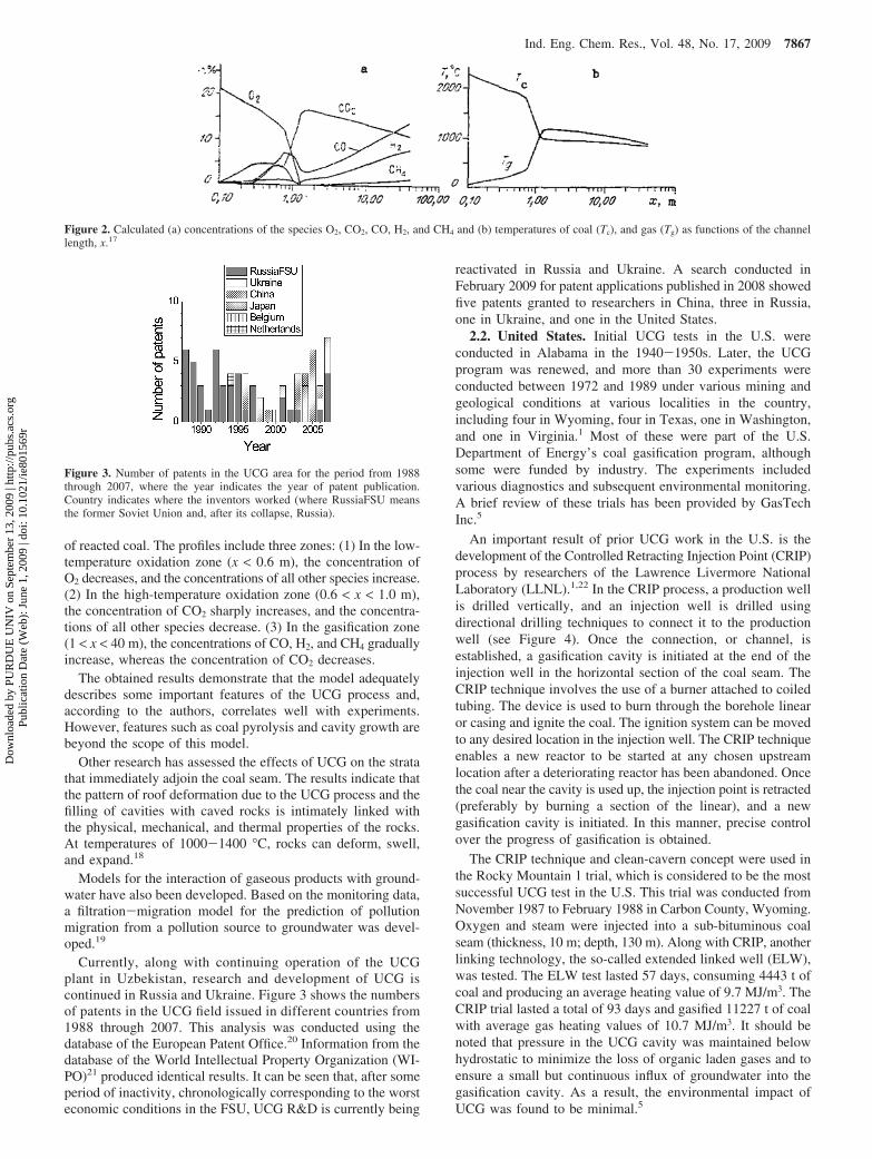
of reacted coal. The profiles include three zones: (1) In the low-temperature oxidation zone (x < 0.6 m), the concentration ofO2 decreases, and the concentrations of all other species increase.(2) In the high-temperature oxidation zone (0.6 < x < 1.0 m),the concentration of CO2 sharply increases, and the concentra-tions of all other species decrease. (3) In the gasification zone(1 < x < 40 m), the concentrations of CO, H2, and CH4 graduallyincrease, whereas the concentration of CO2 decreases.
The obtained results demonstrate that the model adequatelydescribes some important features of the UCG process and,according to the authors, correlates well with experiments.However, features such as coal pyrolysis and cavity growth arebeyond the scope of this model.
Other research has assessed the effects of UCG on the stratathat immediately adjoin the coal seam. The results indicate thatthe pattern of roof deformation due to the UCG process and thefilling of cavities with caved rocks is intimately linked withthe physical, mechanical, and thermal properties of the rocks.At temperatures of 1000-1400 °C, rocks can deform, swell,and expand.18
Models for the interaction of gaseous products with ground-water have also been developed. Based on the monitoring data,a filtration-migration model for the prediction of pollutionmigration from a pollution source to groundwater was devel-oped.19
Currently, along with continuing operation of the UCGplant in Uzbekistan, research and development of UCG iscontinued in Russia and Ukraine. Figure 3 shows the numbersof patents in the UCG field issued in different countries from1988 through 2007. This analysis was conducted using thedatabase of the European Patent Office.20 Information from thedatabase of the World Intellectual Property Organization (WI-PO)21 produced identical results. It can be seen that, after someperiod of inactivity, chronologically corresponding to the worsteconomic conditions in the FSU, UCG R&D is currently being
reactivated in Russia and Ukraine. A search conducted inFebruary 2009 for patent applications published in 2008 showedfive patents granted to researchers in China, three in Russia,one in Ukraine, and one in the United States.
2.2. United States. Initial UCG tests in the U.S. wereconducted in Alabama in the 1940-1950s. Later, the UCGprogram was renewed, and more than 30 experiments wereconducted between 1972 and 1989 under various mining andgeological conditions at various localities in the country,including four in Wyoming, four in Texas, one in Washington,and one in Virginia.1 Most of these were part of the U.S.Department of Energy’s coal gasification program, althoughsome were funded by industry. The experiments includedvarious diagnostics and subsequent environmental monitoring.A brief review of these trials has been provided by GasTechInc.5
An important result of prior UCG work in the U.S. is thedevelopment of the Controlled Retracting Injection Point (CRIP)process by researchers of the Lawrence Livermore NationalLaboratory (LLNL).1,22 In the CRIP process, a production wellis drilled vertically, and an injection well is drilled usingdirectional drilling techniques to connect it to the productionwell (see Figure 4). Once the connection, or channel, isestablished, a gasification cavity is initiated at the end of theinjection well in the horizontal section of the coal seam. TheCRIP technique involves the use of a burner attached to coiledtubing. The device is used to burn through the borehole linearor casing and ignite the coal. The ignition system can be movedto any desired location in the injection well. The CRIP techniqueenables a new reactor to be started at any chosen upstreamlocation after a deteriorating reactor has been abandoned. Oncethe coal near the cavity is used up, the injection point is retracted(preferably by burning a section of the linear), and a newgasification cavity is initiated. In this manner, precise controlover the progress of gasification is obtained.
The CRIP technique and clean-cavern concept were used inthe Rocky Mountain 1 trial, which is considered to be the mostsuccessful UCG test in the U.S. This trial was conducted fromNovember 1987 to February 1988 in Carbon County, Wyoming.Oxygen and steam were injected into a sub-bituminous coalseam (thickness, 10 m; depth, 130 m). Along with CRIP, anotherlinking technology, the so-called extended linked well (ELW),was tested. The ELW test lasted 57 days, consuming 4443 t ofcoal and producing an average heating value of 9.7 MJ/m3. TheCRIP trial lasted a total of 93 days and gasified 11227 t of coalwith average gas heating values of 10.7 MJ/m3. It should benoted that pressure in the UCG cavity was maintained belowhydrostatic to minimize the loss of organic laden gases and toensure a small but continuous influx of groundwater into thegasification cavity. As a result, the environmental impact ofUCG was found to be minimal.5
Figure 2. Calculated (a) concentrations of the species O2, CO2, CO, H2, and CH4 and (b) temperatures of coal (Tc), and gas (Tg) as functions of the channellength, x.17
Figure 3. Number of patents in the UCG area for the period from 1988through 2007, where the year indicates the year of patent publication.Country indicates where the inventors worked (where RussiaFSU meansthe former Soviet Union and, after its collapse, Russia).
Ind. Eng. Chem. Res., Vol. 48, No. 17, 2009 7867
Dow
nloa
ded
by P
UR
DU
E U
NIV
on
Sept
embe
r 13
, 200
9 | h
ttp://
pubs
.acs
.org
P
ublic
atio
n D
ate
(Web
): J
une
1, 2
009
| doi
: 10.
1021
/ie80
1569
r

In parallel to the trials, a number of mathematical modelsfor UCG have also been developed in the U.S. A brief reviewof UCG models developed through the end of 1970s wasprovided by Gregg and Edgar.11 Among later developments,analytical23,24 and numerical25 models should be mentioned.Britten and Krantz23,24 applied the method of activation energyasymptotics to analyze the dynamics of a planar combustionwave traveling in a porous medium in a direction opposed tothe forced oxidant flux, similar to reverse combustion linking.The model assumes an infinite effective Lewis number and one-step, first-order Arrhenius kinetics for this two-phase, oxygen-limited combustion process. The fuel is modeled as a single-component gas-phase species devolatilized from the mediumahead of the combustion zone. The obtained values of steadyfront velocity and front temperature agree well with results ofnumerical calculations. The analysis also determines conditionsfor the extinction of the steady reverse combustion front in termsof the heat loss strength and oxidant flux and shows the existenceof two solutions for heat losses below the extinction value. Thepredicted dependences of the steady front velocity and temper-ature on the heat loss intensity agree qualitatively withexperimental observations.
Britten and Thorsness25 have developed a model describingcavity growth and gas production during UCG in thick (∼10-m) coal layers. It is applicable to the UCG of shrinking coalsin which oxidant injection is maintained at a fixed point low inthe coal seam. The model is based on a few fundamentalassumptions, namely, that the cavity is axisymmetric about theinjection point, all resistance to injected gas flow is throughash and overburden rubble that accumulates on the cavity floor,thermal radiation dominates in the well-mixed void space, andthe coal and overburden spall or rubble on a small scale as aresult of parametrized thermal effects. A unified model integratesresults of separate but interacting submodels that describe keyphenomena occurring at different locations in and around theUCG reactor, as shown in Figure 5. These submodels quantifywater influx from the coal aquifer; flow dispersion through arubble bed at the bottom of the cavity; thermal degradation andchemical attack of rubble-covered coal sidewalls contacted bythe injected reactants; and recession of cavity surfaces enclosinga void space in the upper cavity, caused by small-scalefragmentation and gasification driven primarily by radiative heattransfer. The model predicts recession rates of cavity surfacesand generation rates of major product species that compare wellwith experimental data from two UCG field tests. For example,Figure 6 shows H2 and CO production rates in the first twoCRIP reactors during the Rocky Mountain I UCG field test. Itcan be seen that the model predictions are in accord with the
measurements. The drop in flows around day 53 is due topurposely lowered injection flows immediately before and afterthe CRIP pipe-cutting maneuver that initiated the second reactor.Note, however, that the Rocky Mountain I field tests wereconducted in a thick (7.6-m) seam and the model might not beapplicable for thinner seams (discussed later in section 2.3).
The research in the U.S. has highlighted the importance ofassessing the geological and hydrogeological settings for UCG.A recent investigation at LLNL was focused on geomechanicalprocesses in coal and surrounding rocks during UCG.26 A suite
Figure 4. Schematic of the CRIP process.1
Figure 5. Schematic of the UCG cavity and occurring processes.25
Figure 6. Model predictions of H2 and CO production rates compared withfield data.25
7868 Ind. Eng. Chem. Res., Vol. 48, No. 17, 2009
Dow
nloa
ded
by P
UR
DU
E U
NIV
on
Sept
embe
r 13
, 200
9 | h
ttp://
pubs
.acs
.org
P
ublic
atio
n D
ate
(Web
): J
une
1, 2
009
| doi
: 10.
1021
/ie80
1569
r

of highly nonlinear computational tools in both two and threedimensions was applied to a series of UCG scenarios. Thesimulations included combinations of continuum and discretemechanical responses by employing fully coupled finite-elementand discrete-element capabilities.
After the decline of oil and gas prices in the early 1980s,large-scale UCG projects were not conducted in the U.S. Inrecent years, because of growing energy needs, interest in UCGhas been rejuvenated. BP and GasTech Inc. are developing aUCG demonstration project in the Powder River Basin (WY)that will be followed by a commercial-scale UCG project. InJuly 2007, BP and LLNL signed a technical cooperationagreement on UCG. The initial two-year technical agreementaddresses three broad areas of UCG technology: carbonmanagement to evaluate the feasibility of carbon dioxide storageunderground, environmental risk assessment and management,and numerical modeling of the UCG processes to understandpilot-test results and match them with historical data. Thetechnical objective is for LLNL to provide BP with expertise,model results, new capabilities, and insights into the operationand environmental management of UCG.27
The issue of carbon management during the UCG process isan important aspect of UCG development in the U.S.1,28 It isnoted that all three main approaches to CO2 capture in surfacepower plants (precombustion, postcombustion, and oxy-fuel) canbe combined with UCG. There are two options for usinggeological CO2 sequestration with UCG. One option is to useseparate cavities for CO2 storage, and the other is to use thecavities that were formed during UCG. The latter option isattractive (for example, because of reduced costs for drilling,etc.), but there are limitations and problems that require furtherinvestigation.29 Note that the cavity should be located deeperthan 800 m, so that CO2 can be stored in the supercritical state,allowing significantly higher utilization of the pore spaceavailable. The potential risks include sudden phase changesduring CO2 injection, adverse geomechanical and geochemicalresponses, groundwater displacement, and CO2 leakage.1
2.3. European Union. A number of UCG tests have beencarried out in Western Europe. A significant difference of thesetests is the large depth of coal seams (600-1200 m, as comparedwith <300 m in the FSU and U.S.).
In France, the first trial was conducted30 at Bruay en Artois(coal seam thickness, 1.2 m; depth, 1170 m) in 1980-1981.Two technological and five monitoring wells were drilled. Thedistance between the injection and production wells was 65 m.Hydraulic fracturing (pressure, 50.7 MPa) did not lead to asatisfactory link between the wells. Attempts to use reversecombustion linking also failed because of coal self-ignition nearthe injection well. The main reason for the failure of thisexperiment was apparently a poor hydraulic connection betweenthe wells, which led to the need for high pressure in the reversecombustion procedure and, as a result, to the coal self-ignition.The second trial was conducted31 at La Haute Deule (coal seamthickness, 1.8 m; depth, 880 m) in 1983. Two vertical wellswere drilled (distance, 60 m). The hydraulic fracturing andreverse combustion linking were again unsuccessful. In bothtrials, gasification of the coal seam was not achieved.
In the framework of a joint Belgium-Germany project, UCGtrials were conducted near Thulin, Belgium.32-34 In 1982, fourwells were drilled, and an attempt to link them by reversecombustion was unsuccessful. A new attempt in 1984 also failed.Subsequent attempts to gasify coal resulted in the productionof small portions of gas with different compositions, but
hydraulic resistance between the wells remained large, indicatingthat the wells were not linked properly.
In the 1990s, a UCG project of the European Union wasconducted by Spain, the U.K., and Belgium at El Tremedal inthe Province of Teruel, Spain, which was chosen based on itsgeological suitability, coal seam depth (550 m), and extensiveset of available borehole data.35,36 The objectives were to testthe use of directional drilling to construct the well configurationand to evaluate the feasibility of gasification at depths greaterthan 500 m. The injection well, obtained by directional drilling,had vertical and horizontal parts as in the CRIP technique (seeFigure 4). Three attempts to create the UCG process usingoxygen were undertaken. During the experiments, continuouspressure monitoring was conducted, and pressure was main-tained close to the hydrostatic value at the coal seam depth (5.3MPa). The first attempt lasted 9 days and resulted in theproduction of a gas mixture containing 24.9% H2, 8.7% CO,14.3% CH4, 43.4% CO2, and 8.3% H2S, with a heating value10.97 MJ/m3. The second test lasted 3 days and produced asimilar gas composition of 24.7% H2, 15.6% CO, 12.4% CH4,39.4% CO2, and 8.8% H2S, with a heating value 10.9 MJ/m3.During the third test, technical problems, such as a malfunctionof the ignition system and a failure of the temperature measure-ment system, resulted in the accumulation of methane and asubsequent explosion. The injection well was damaged, and thedecision was made to terminate the trial.
It should be noted that the high gas pressure used in theEuropean trials led to higher concentrations of methane inthe product gas.35 This can be illustrated by comparison withthe results of the UCG trial at 0.4 MPa (U.S.), where oxygenwas also used. The gas obtained at 0.4 MPa contained 38.1%H2, 20.8% CO, 4.7% CH4, 34.9% CO2, and 1.5% H2S. Theeffect of pressure is simply a consequence of the methanationreaction (eq 12). Because the volume decreases during thisreaction, according to Le Chatelier’s principle, an increase inpressure shifts the equilibrium to the right, so that the yield ofmethane increases.
In the 1990s, in addition to experiments, numerical modelsof the cavity growth in thin coal seams were developed inBelgium37-39 and The Netherlands.40-42 For UCG in thin (<2m) European seams, the permeable-packed-bed concept usedby Britten and Thorsness25 (see section 2.2) is applicable onlyduring the initial stages of the gasification process. Theresearchers in Europe have developed channel-gasificationmodels, based on a simplified description proposed by Wilks43
and postulated two zones in the UCG gasifier: a low-perme-ability zone of rubble/ash around the injection well and a high-permeability, narrow, peripheral zone near the coal wall (Figure7). The Belgian group developed a two-dimensional model forUCG cavity growth in thin seams.39 The model combineslaminar flow through a porous medium around the injectionpoint with the calculation of chemical processes in the peripheralzone adjacent to the coal wall. Figure 8 shows the calculatedcavity shape and stream lines around the injection point. Thebottom image corresponds to the situation where the low-permeability zone reaches the production well. This criterioncan be used to define the end of the gasification process.
The Dutch group developed a two-dimensional, quasi-steady-state model of a laterally extending, partially collapsing gasifica-tion channel.40 The model includes the chemistry of coalgasification, diffusional transport phenomena, pyrolysis of coal,and radiant heat exchange within the channel and with spallingcap rock. The quasi-steady-state approach leads to relativelysimple model equations in which only one single cross-sectional
Ind. Eng. Chem. Res., Vol. 48, No. 17, 2009 7869
Dow
nloa
ded
by P
UR
DU
E U
NIV
on
Sept
embe
r 13
, 200
9 | h
ttp://
pubs
.acs
.org
P
ublic
atio
n D
ate
(Web
): J
une
1, 2
009
| doi
: 10.
1021
/ie80
1569
r

element of the channel needs to be considered. The model wasused to demonstrate the influence of operating conditions suchas pressure, air injection rate, and water injection rate on theproduct gas composition. A comparison between observationsfrom the UCG field test (seam thickness, 2 m) in Pricetown,West Virginia, and model predictions showed similar gascomposition and process temperatures.
Later, the Dutch group developed a more comprehensivemodel41,42 for studying the transport phenomena in UCG cavitiesbased on a finite volume discretization of the Navier-Stokesequations and the k-ε turbulence model. Depending on the
operating conditions, the fluid flow was dominated by eitherbuoyancy due to temperature or concentration gradients. Thepredicted composition and heating value of the product gas werein good agreement with both the experimental data from thePricetown field test and the results of simplified model.40
In the U.K., the Department of Trade and Industry Technol-ogy (DTI) identified UCG as one of the potential futuretechnologies for the development of the U.K.’s large coalreserves.4 An initial prefeasibility study was completed inJanuary 2000 by the DTI in conjunction with The CoalAuthority, and work then began on the selection of a U.K. sitefor a drilling and in-seam gasification trial. Detailed work wasdone on the geological and hydrogeological criteria for UCG,the evaluation of suitable sites, and the legislative policies thatwould apply to an onshore UCG scheme. This work emphasizedthe growing importance of environmental issues, and a thoroughinvestigation of these issues will likely be undertaken beforelegislative approval of a test site. Sury et al.6,7 provided adetailed analysis of the environmental aspects of UCG.
Currently, the Hydrogen Oriented Underground Coal Gas-ification for Europe (HUGE) project is being conducted byresearch organizations in Poland and several other countries ofthe European Union.44 Major attention in this project is paid tothe integration of gasification processes with heat- and mass-transfer phenomena occurring in geological multiphase systemsof complex geometry. Valuable expertise from UCG, geologicalCO2 storage, and enhanced oil recovery is being compiled,critically assessed, and used as building blocks in designing thehydrogen-oriented UCG plant. The concept of a georeactor thatintegrates UCG with geothermal heat exchange and with carboncapture and storage is being investigated.
2.4. China. It is generally believed that China has thelargest UCG program currently underway. This is confirmedby the relatively large number of patents in the UCG areathat have been obtained by Chinese engineers (see Figure2). Since the late 1980s, many UCG trials have been carriedout or are currently operating. Chinese trials utilize abandonedgalleries of used coal mines for the gasification. Verticalboreholes are drilled into the gallery to act as the injection andproduction wells.
Researchers at the China University of Mining and Technol-ogy investigated the two-stage UCG process proposed in theearly 1930s in the USSR45 for the production of hydrogen, inwhich a system of alternating air and steam injection is used.The experiments, conducted in Woniushan coal mine, Xuzhou,Jiangsu Province, confirmed the feasibility of using UCG forlarge-scale hydrogen production.46
Current technological projects include construction of a pilotindustrial UCG plant at the Gonggou coal mine, Wulanchabu,
Figure 7. Schematic of a UCG reactor in thin seams.39
Figure 8. Cavity shape and stream lines after 0, 5, 10, 15, and 18 days ofgasifier development,39 for a 50-m distance between injection and productionwells.
7870 Ind. Eng. Chem. Res., Vol. 48, No. 17, 2009
Dow
nloa
ded
by P
UR
DU
E U
NIV
on
Sept
embe
r 13
, 200
9 | h
ttp://
pubs
.acs
.org
P
ublic
atio
n D
ate
(Web
): J
une
1, 2
009
| doi
: 10.
1021
/ie80
1569
r

Northern Inner Mongolia Autonomous Region. The $112 millionproject is a joint venture between the China University of Miningand Technology and Hebei Xin’ao Group.
2.5. Canada. In Canada, Ergo Exergy Technologies Inc. isa small but active UCG development company. According tothe information on the company’s Web site,47 prior to foundingthe company in 1994, the principals of Ergo Exergy worked atthe Angren UCG plant in Uzbekistan. Recently, Ergo Exergyexperts completed a UCG trial in Australia (see section 2.6).They are currently working on a UCG pilot plant in South Africa(see section 2.7). It should be noted that, according to ErgoExergy, they use their proprietary εUCG technology. Burton etal.1 suggest the εUCG might be based on the old Soviet UCGtechnology.
Laurus Energy Inc., an exclusive Canadian licensee of theεUCG technology, is developing a commercial project targetingpower generation and supply of fuel and hydrogen for the localindustrial markets near Edmonton, Alberta, Canada. The startedproject development includes regulatory and environmentalapprovals, site selection and a prefeasibility study, and a sitecharacterization program.48 Note that coal gasification can beused to generate steam for oil recovery from tar sands, whichare a major source of oil in Canada.49
In addition, Michael Blinderman, a director of Ergo Exergy,collaborates with researchers at the University of Queensland(Australia) in modeling the UCG process. Recently, they havedeveloped new models for reverse and forward combustionregimes in UCG.50-52 In contrast with the earlier model,23,24
both oxygen-deficient and coal-deficient cases were analyzed.Hydrodynamic and pulsating stability were considered, andspecial attention was paid to the vicinity of the stoichiometricpoint. Also, curved flames were analyzed in this work. Alongwith asymptotic methodologies, in several instances, simplifiedformulations were used, and compact analytical representationswere obtained. This approach resulted in an overall theory ofreverse combustion linking during UCG that determines therelationships between key parameters of the process. Preliminaryresults of applying the theory to specific UCG conditionsdemonstrated reasonable conformity with the data obtained inpractical UCG operations. For example, Figure 9 shows thespeed of reverse combustion linking as a function of the suppliedair flow rate. It can be seen that the predicted values are ingood agreement with the experimental data from the Chinchillatrial. For forward combustion, a two-dimensional model was
developed, assuming quasi-stationary flow of gas through a thincoal seam. It was shown that the speed and efficiency of forwardcombustion linking are significantly lower than those of reversecombustion, which correlates with prior experimental results.
2.6. Australia. The development of UCG technology inAustralia was advocated by Prof. Ian Stewart of the Universityof Newcastle. In 1983, his program of laboratory research wasfollowed by a government funded feasibility study of UCG atthe Leigh Creek coal mine in South Australia. The studyconcluded that the use of UCG gas as a fuel for combustion ingas turbines would be cost competitive with other sources ofpower.53 Currently, commercial UCG projects are being devel-oped by at least three Australian companies: Cougar EnergyLtd., Linc Energy Ltd., and Carbon Energy Ltd.
The Managing Director of Cougar Energy, Dr. Len Walker,has actively pursued an interest in UCG since 1982. In 1996,he formed an association with Dr. Michael Blinderman fromErgo Exergy. Together, they initiated a UCG trial at Chinchillain South East Queensland, conducted between 1999 and 2002.54
Cougar Energy is planning to use Ergo Exergy’s εUCGtechnology in the current projects. In Queensland, CougarEnergy has completed resource definition at its Kingaroy siteand is undertaking final site characterization prior to commenc-ing the pilot burn for a 400 MW combined-cycle power project.In Victoria, Cougar Energy’s plan is to determine whethersignificant localized deposits of Victorian lignite exist that mightbe suitable for application of the UCG process.
The aforementioned Chinchilla trial was conducted by LincEnergy, using the technology provided by Ergo Exergy. Theproject involved drilling 9 injection/production wells and 19monitoring wells to a coal seam at the average depth 140 m.During the project period, 35000 t of coal was gasified, with95% recovery of the coal resource and 75% total energyrecovery. This resulted in the production of 80 × 106 Nm3 ofgas (heating value, 4.5-5.7 MJ/m3). Results from an evaluationof the product gas composition showed that gas turbine unitscan operate satisfactorily on air-blown UCG gas. A maximumcapacity of 80000 N m3/h (675 t of coal per day) was reached,and the availability of gas production over 30 months wasdemonstrated. The Chinchilla project also demonstrated thefeasibility of controlling the UCG process, including shutdownand restart, and resulted in successful environmental perfor-mance according to independent audit reports. Specifically, nogroundwater contamination was registered, no subsidence oc-curred, no surface contamination was detected, and no envi-ronmental issues were identified.
It should be noted that, at the end of 2006, the collaborationbetween Linc Energy and Ergo Exergy was terminated. InDecember 2006, Linc Energy signed cooperation agreementswith the Skochinsky Institute of Mining in Moscow, Russia,and its parent organization, the Scientific-Technical MiningAssociation. In October 2007, Linc Energy acquired a control-ling interest in Yerostigaz, which owns the UCG site in Angrenin Uzbekistan. With the additional experienced employees andexpertise from Russia and Uzbekistan, Linc Energy plans tomove forward on expanding UCG operations in Australia (acommercial UCG and coal-to-liquids plant) and other coun-tries.53
Carbon Energy Ltd. is using CRIP technology and modelingpackages for site selection, process design, and process control,developed at the Commonwealth Scientific and IndustrialResearch Organization (CSIRO).55 Carbon Energy plans a large-scale demonstration trial at Bloodwood Creek, in the Surat Basinin Queensland. In September 2008, Carbon Energy announced
Figure 9. Predicted (curve) and experimental (points) speed of reversecombustion linking as a function of the air flow rate.50
Ind. Eng. Chem. Res., Vol. 48, No. 17, 2009 7871
Dow
nloa
ded
by P
UR
DU
E U
NIV
on
Sept
embe
r 13
, 200
9 | h
ttp://
pubs
.acs
.org
P
ublic
atio
n D
ate
(Web
): J
une
1, 2
009
| doi
: 10.
1021
/ie80
1569
r

successful completion of the directional drilling program, whichinvolved creating two parallel 850-m-long in-seam wells and avertical ignition well.55 The trial will be performed as the firstmodule of a commercial facility for generation of 1 PJ per yearof syngas with a three-year module life. It is planned that eachmodule will produce enough syngas to generate 20 MW ofelectricity in a combined-cycle gas-turbine power plant.
Along with the commercial developments described above,several research projects on the modeling of UCG processeshave been conducted at CSIRO, the University of Queens-land50-52 (see section 2.5), and the University of New SouthWales.56-58 Perkins and Sahajwalla56,57 developed a one-dimensional model of a reacting coal block to investigate theeffects of operating conditions and coal properties on the localrate of cavity growth and energy effectiveness in UCG process.The investigation revealed that the cavity growth rate is mostsensitive to the operating temperature, water influx, and gaspressure. The coal properties that most affect the cavity growthrate are the thermomechanical spalling behavior, the behaviorof the ash, and the amount of fixed carbon in the coal. Manytrends observed in the field trials are reproduced by the modelsimulations, and predicted cavity growth rates for six field trialsare comparable to those observed (Figure 10).
More recently, Perkins and Sahajwalla58 developed a two-dimensional axisymmetric CFD model of a UCG cavity partiallyfilled with ash. Simulations revealed that, when bottom injectionof the oxidant is applied, the flow in the void space above theash bed is dominated by a single buoyant force due totemperature gradients established by combustion. Optimumoxygen injection rates can be found that maximize the produc-tion of chemical energy in the product gas. When the oxidantis injected into the cavity from the top, most of the valuablegasification products are oxidized, leading to a product gas witha high temperature and a low caloric value. The simulationselucidate the important transport and reaction processes occur-ring in the underground cavity, and the results are in qualitativeagreement with observations from UCG field trials.
2.7. South Africa. Eskom, a coal-fired utility in South Africa,has been investigating UCG at its 4100 MW Majuba powerplant since 2001, using Ergo Exergy’s εUCG technology. Bythe end of 2008, the project generated about 15000 m3/h of flaredgas.16 The Eskom pilot project will be expanded in a stagedmanner, based on the success of the each preceding phase. Theultimate objective of the project is to fully evaluate thetechnology and produce a business case for the cofiring of 1200MW of electricity at Majuba. The natural progression for UCGproceeds into integrated gasification combined cycle (UCG-IGCC) and into other unminable coal resources in South Africa.
Eskom’s preliminary estimates show that there is 45 Gt of coalin South Africa that is presently regarded as unminable withcurrently available technologies but is still suitable for UCG.This will create a new energy source for Eskom that will enablethe present generating capacity of 41 GW to be increased9-fold.59
2.8. New Zealand. In 1994, a UCG project was undertakenin the Huntly coal reserve, 120 km south of Auckland. The testwas carried out over a 13-day period, and approximately 80 tof coal was consumed during reverse combustion linking offive vertical wells, which, however, was not followed by propergasification.16
New Zealand is a tectonically active country, which hasresulted in the coal deposits being both faulted and folded and,in some cases, laid down on undulating basement topography.This geological complexity presents considerable technicalchallenges to the successful planning and extraction of coal.Solid Energy New Zealand Ltd. is planning to use UCG tocomplement currently employed mining methods, for low-costaccess to coal that is currently not technically or economicallyaccessible. Solid Energy has exclusive rights to apply ErgoExergy’s εUCG technology within New Zealand and is currentlyinvestigating the potential for the application of UCG there.60
2.9. India. UCG is a promising technology for India, whichhas vast coal resources, primarily of low grade. India looks toutilize its coal reserves, which are the fourth-largest in the world,to reduce dependency on oil and gas imports. UCG is expectedto be used to tap India’s coal reserves, which are difficult toextract economically using conventional technologies. The Oiland Natural Gas Corporation Ltd. (ONGC) is planning to carryout pilot projects using recommendations of experts from theSkochinsky Institute of Mining in Moscow.61 The Gas Authorityof India Ltd. (GAIL) and AE Coal Technologies India Pvt.Limited, a company belonging to the Abhijeet Group of India,are implementing UCG projects using Ergo Exergy’s εUCGtechnology.62
Recently, computational fluid dynamics studies of complexflow patterns in a growing UCG cavity were conducted byresearchers of IIT-Bombay in collaboration with ONGC.63 Themain objective of this work was to understand the velocitydistribution and perform residence time distribution (RTD)studies in the UCG cavity. Based on the RTD studies, the actualUCG cavity at different times was modeled as a simplifiednetwork of ideal reactors, which might offer a computationallyless expensive and easier option to determine UCG processperformance as a function of time.
2.10. Japan. Japan, which has substantial coal interestsoutside its borders, as well as continental shelf resources, hasincluded UCG in its future research plans for coal exploitationand has been maintaining a low-level program for many years.The University of Tokyo and coal companies have beenconducting technical and economic studies of UCG on a smallscale and are considering conducting a trial in the near future.A feasibility study has been undertaken for a UCG trial, forwhich a 55 km2 site area was selected.64 Predictions were basedon analysis of field data from UCG trials in the U.S. The studyidentified the largest cost elements as drilling and oxygen.
3. Criteria for UCG Site Selection
The determination of selection criteria for UCG locations isan important problem. The criteria for underground mining,including technological and land-use restrictions, are well-known, but in some cases, the criteria for UCG are expected tobe different. For example, the UCG process has specific
Figure 10. Comparison of estimated cavity growth rates from six UCGfield trials with model simulations.57
7872 Ind. Eng. Chem. Res., Vol. 48, No. 17, 2009
Dow
nloa
ded
by P
UR
DU
E U
NIV
on
Sept
embe
r 13
, 200
9 | h
ttp://
pubs
.acs
.org
P
ublic
atio
n D
ate
(Web
): J
une
1, 2
009
| doi
: 10.
1021
/ie80
1569
r

requirements for the depth and thickness of coal seams that differfrom those applicable to mining.
3.1. Thickness of Coal Seam. The available information onthe minimum seam thickness for UCG is somewhat contradic-tory. GasTech5 indicates that the optimal thickness should bemore than 10 m. However, that report considered coal seamsof the Powder River Basin, Wyoming, which are mainly from10 to over 30 m in thickness. On the contrary, Ergo Exergystates that UCG can be used in coal seams as thin as 0.5 m.47
As mentioned above, UCG work in the FSU showed that theheating value of the produced gas decreases significantly withdecreasing coal thickness below 2 m (see Figure 1), so this valuemight be considered a desirable lower limit.
3.2. Depth of Coal Seam. Our analysis of the UCG literatureshows that the depth of coal seams is not a critical parameter.The depth varied from 30 to 350 m in the FSU developmentsand U.S. experiments, whereas Western European trials wereconducted in much deeper coals (600-1200 m). The LLNLexperts indicate that the minimum depth should be 12 m.1 Onthe other hand, relatively shallow coal seams are generally usedfor surface mining. Sixty meters is the typically applied limitto the depth of surface mining and is therefore considered abounding limit in this analysis. For example, the IndianaGeological Survey has used 200 feet (∼60 m) as the maximumdepth for surface mining.65 Taking into account the relativelylow cost of surface mining and assuming that use of thistechnology will continue, it is reasonable to expect that coalswith depths of less than 60 m have low suitability for UCG.Additionally, the proximity of potable and potentially potablegroundwater supplies at this shallow depth discourages furtherconsideration of those coals that are located near the groundsurface.
To decrease the risk of subsidence, Burton et al.1 recommendoperational depths of >200 m. Depths of more than 300 mrequire more complicated and expensive drilling technologies,but they also have advantages such as minimized risk ofsubsidence and the possibility of conducting the UCG processat higher pressure, which increases the heating value of theproduced gas. Also, deeper seams are less likely to behydrologically linked with potable aquifers, thus avoidingdrinkable water contamination problems. Further, if the productgas is to be used in gas turbines, additional compression mightnot be necessary. Finally, UCG cavities at depths of more than800 m could be used for CO2 sequestration.
If potential UCG sites are found at different depths, furtheranalysis should be made based on tradeoffs between the highercosts of deeper wells and the advantages of UCG productionfrom greater depths. As mentioned above (see section 2.3), amajor advantage of using deeper coals for UCG is the highergasification pressure, which yields a higher methane contentand hence a higher heating value. Of course, if the intent is toproduce chemicals and/or liquid fuels from the gasified coal,then maintaining high CO and H2 contents, rather than a highpercentage of methane, is of interest.
3.3. Coal Rank and Other Properties. With the presentstate of knowledge, low-rank, high-volatility, noncaking bitu-minous coals are preferable. UCG might work better on lower-rank coals because such coals tend to shrink upon heating,enhancing permeability and connectivity between injection andproduction wells.1 Also, the impurities in lower-rank coals mightimprove the kinetics of gasification by acting as catalysts forthe burn process. For coals of the same rank, the heating valueof the UCG gas increases with increasing heating value of thecoal.
The values of porosity and permeability within the coal seammight also be important factors, but it is difficult to use themas criteria at this point because of the scarcity of such data.Better cleated and more permeable seams allow for moreeffective connection between the injection and production wells,leading to faster transport of reactants and a higher rate ofgasification. On the other hand, higher porosity and permeabilityincrease the influx of water and increase product gas losses.
Also, it is often recommended that coals should not exhibitsignificant swelling upon heating. In particular, Sury et al.6 havestated that, in general, reverse combustion works well in shallownonswelling coal but is not recommended for use at great depthsand in swelling coals. This contradicts, however, the opinionof Burton et al.,1 who noted that the FSU methods demonstratedminimum sensitivity to coal swelling: the large-dimensionchannels formed in the linkage process employed in thoseoperations did not appear to be plugged by coal swelling. Areasof seams that are free of major faulting in the vicinity (<45 m)of the proposed gasifier and that could potentially provide apathway for water inflow or gas migration should be preferen-tially targeted.7
3.4. Dip of Coal Seam. Sury et al.7 have indicated thatshallow dipping coal seams are preferable. Such seams facilitatedrainage and the maintenance of hydrostatic balance within thegasifier; they also minimize potential damage to the down dipproduction well from material that is moved in association withthe UCG process. A report by GasTech5 recommends dip anglesof 0-20°. However, UCG has been successfully carried out insteeply dipping seams;8 thus, dip is not a critical constrainingfactor for selecting and operating UCG sites.
3.5. Groundwater. Water is an essential component of theUCG process, and thus its availability either from within a coalseam or from a source adjoining the seam is an importantcharacteristic. The adjoining rocks must contain saline water(>10000 ppm total dissolved solids, as per U.S. EnvironmentalProtection Agency regulations) and have a significant deliverablevolume. In many cases, the coal itself serves as the principleaquifer within the stratigraphic section and is bounded byimpermeable shales and low-density rock. In some cases,permeable sandstones form the roof rock and therefore are inhydrological connectivity with strata outside the coal seam. Suryet al.7 recommended using coal seams with no overlying potableaquifers within a distance of 25 times the seam height. Trialshave been successfully carried out in seams in closer proximityto potable underground aquifers, but the potential risk ofcontamination increases in such a setting.
3.6. Amount of Coal. Gas produced by the undergroundgasification process can potentially be used in several applica-tions. These applications range from supplying mobile units thatcould provide gas in agricultural areas to supporting large powerand chemical plants producing hundreds to thousands ofmegawatts of electrical energy and vast amounts of hydrocarbon-based products. For this reason, the evaluation of potentiallyproductive sites must include the determination of the amountof coal available in a gasification project in conjunction with aconsideration of the potential applications of the produced gas.Additionally, for each potential site, the productive lifetime ofthe site must be determined as a function of required gas yield.For illustration, for 20-year continuous operation of a 300 MWUCG-based combined-cycle power plant (efficiency, 50%), itis necessary to produce 75.6 × 10⁹ Nm3 of syngas with a heatingvalue of 5 MJ/m3. Based on the Chinchilla experimental data(see section 2.6), 33 × 106 metric tons needs to be gasified forthis purpose. Note that this amount can be decreased by a factor
Ind. Eng. Chem. Res., Vol. 48, No. 17, 2009 7873
Dow
nloa
ded
by P
UR
DU
E U
NIV
on
Sept
embe
r 13
, 200
9 | h
ttp://
pubs
.acs
.org
P
ublic
atio
n D
ate
(Web
): J
une
1, 2
009
| doi
: 10.
1021
/ie80
1569
r

of 2 by using oxygen and steam as injection gases, which,however, increases the cost.
3.7. Land-Use Restrictions. There is no indication in theliterature that UCG should be farther from towns, roads, andother objects than underground mines, assuming that the processdesign and environmental monitoring eliminate water contami-nation and air pollution. Thus, the land-use restrictions forunderground mining can be applied to potential UCG sites.
4. Summary and Recommendations
Our analysis of the current status of UCG shows that thistechnology has a great potential to grow and replace/complementtraditional methods for coal mining and surface gasification.New commercial UCG projects have started recently in severalcountries, and more projects will probably start soon. Selectionof the best UCG technology is a complex process, and a varietyof technical and geological factors must be taken into consid-eration for each site being evaluated.
Acknowledgment
It is a pleasure to participate in this celebration of ProfessorJ. B. Joshi. Acknowledgment is made to the Indiana Center forCoal Technology Research for financial support of this work.The authors also thank Drs. Maria Mastalerz and John Rupp ofthe Indiana Geological Survey for useful discussions, as wellas reviewers for thorough reviews of the manuscript and helpfulsuggestions.
Literature Cited
(1) Burton, E.; Friedmann, J.; Upadhye, R. Best Practices in Under-ground Coal Gasification; Contract W-7405-Eng-48; Lawrence LivermoreNational Laboratory: Livermore, CA, 2006.
(2) Creedy, D. P.; Garner, K. Clean Energy from Underground CoalGasification in China; DTI Cleaner Coal Technology Transfer Programme;Report COAL R250; DTI/Pub URN 03/1611; Department of Trade andIndustry Technology (DTI): London, 2004.
(3) Creedy, D. P.; Garner, K.; Holloway, S.; Jones, N.; Ren, T. X. ReViewof Underground Coal Gasification Technological AdVancements; ReportCOAL R211; DTI/Pub URN 01/1041; Department of Trade and IndustryTechnology (DTI): London, 2001.
(4) ReView of the Feasibility of Underground Coal Gasification in theUK; Cleaner Fossil Fuels Programme; DTI/Pub URN 04/1643; Departmentof Trade and Industry Technology (DTI): London, 2004.
(5) Viability of Underground Coal Gasification in the “Deep Coals” ofthe Powder RiVer Basin, Wyoming; Prepared for the Wyoming BusinessCouncil Business and Industry Division State Energy Office; GasTech, Inc.:Casper, WY, 2007.
(6) Sury, M.; White, M.; Kirton, J.; Carr, P.; Woodbridge, R.; Mostade,M.; Chappell, R.; Hartwell, D.; Hunt, D.; Rendell N. ReView of EnViron-mental Issues of Underground Coal Gasification; Report COAL R272; DTI/Pub URN 04/1880; Department of Trade and Industry Technology (DTI):London, 2004.
(7) Sury, M.; White, M.; Kirton, J.; Carr, P.; Woodbridge, R.; Mostade,M.; Chappell, R.; Hartwell, D.; Hunt, D.; Rendell N. ReView of EnViron-mental Issues of Underground Coal GasificationsBest Practice Guide;Report COAL R273; DTI/Pub URN 04/1881; Department of Trade andIndustry Technology (DTI): London, 2004.
(8) Kreinin, E. V. Nontraditional Thermal Technologies for Productionof HeaVy-Extractable Fuels: Coal, Hydrocarbons; OAO Gazprom: Moscow,Russia, 2004 (in Russian).
(9) Lazarenko, S. N.; Kreinin, E. V. Underground Coal Gasification inKuzbass: Present and Future; Institute of Coal, Siberian Branch of theRussian Academy of Sciences, Nauka: Novosibirsk, Russia, 1994 (inRussian).
(10) Lazarenko, S. N.; Kreinin, E. V. Underground Coal Gasificationin Kuzbass: New Opportunities; Institute of Coal and Geochemistry, SiberianBranch of the Russian Academy of Sciences: Kemerovo, Russia, 2006 (inRussian).
(11) Gregg, D. W.; Edgar, T. F. Underground Coal Gasification. AIChEJ. 1978, 24, 753–781.
(12) Kreinin, E. V.; Fedorov, N. A.; Zvyagintsev, K. N.; Pyankova, T. M.Underground Gasification of Coal Seams; Nedra: Moscow, Russia, 1982(in Russian).
(13) Antonova, R. I.; Bezhanishvili, A. E.; Blinderman, M. S. Under-ground Coal Gasification in the USSR; TsNIEIugol: Moscow, Russia, 1990(in Russian).
(14) Kreinin, E. V.; Dvornikova, E. V. Does In-Situ Gasification of CoalSeams Cause Pollution of Underground Water. Ugol′ 1993, 4, 39–40 (inRussian).
(15) Dvornikova, E. V. Role of Sorption Properties of GZh-Grade Coalin Self-Purification of Groundwaters. Ugol′ 1996, 5, 45–47 (in Russian).
(16) Blinderman, M. S. Ergo Exergy, Montreal, Canada. Personalcommunication, 2008.
(17) Kreinin, E. V.; Shifrin, E. I. Mathematical Model of CoalCombustion and Gasification in a Passage of an Underground Gas Generator.Combust., Explos., Shock WaVes 1993, 29, 148–154.
(18) Den’gina, N. I.; Kazak, V. N.; Pristash, V. V. Changes in Rocks atHigh Temperatures. J. Min. Sci. 1994, 29, 472–477.
(19) Kreinin, E. V.; Dvornikova, E. V. Forecast of Spreading of Zonesof Pollution Source Interaction with Groundwater. Dokl. Akad. Nauk 1999,365 (3), 371–373 (in Russian).
(20) Database of the European Patent Office available at http://ep.espacenet.com/?locale)en_ep (accessed March 2009).
(21) Database of the World Intellectual Property Organization (WIPO)available at http://www.wipo.int/pctdb/en (accessed March 2009).
(22) Hill, R. W. Review of the CRIP Process. In Proceedings of the12th Annual Underground Coal Gasification Symposium; DOE: Washington,DC, 1986 (Report DOE/FE/60922-H1).
(23) Britten, J. A.; Krantz, W. B. Linear Stability of Planar ReverseCombustion in Porous Media. Combust. Flame 1985, 60, 125–140.
(24) Britten, J. A.; Krantz, W. B. Asymptotic Structure of PlanarNonadiabatic Reverse Combustion Fronts in Porous Media. Combust. Flame1986, 65, 151–161.
(25) Britten, J. A.; Thorsness, C. B. A Model for Cavity Growth andResource Recovery during Underground Coal Gasification. In Situ 1989,13, 1–53.
(26) Morris, J.; Vorobiev, O.; Antoun, T.; Friedmann, S. J. Geome-chanical Simulations Related to UCG Activities. Presented at the Twenty-Fifth Annual International Pittsburgh Coal Conference, Pittsburgh, PA, Sep29-Oct 2, 2008; Paper 32-3.
(27) BP and LLNL Sign Technical Cooperation Agreement on Under-ground Coal Gasification; LLNL News Release NR-07-07-03; LawrenceLivermore National Laboratory: Livermore, CA, 2007; available athttps://publicaffairs.llnl.gov/news/news_releases/2007/NR-07-07-03.html.
(28) Friedmann, S. J. North America Prospects for UCG in a CarbonConstrained, Energy Secure World. Presented at the Twenty-Fifth AnnualInternational Pittsburgh Coal Conference, Pittsburgh, PA, Sep 29-Oct 2,2008; Paper 26-1.
(29) Blinderman, M. S.; Friedmann, S. J. Underground Coal Gasificationand Carbon Capture and Storage: Technologies and Synergies for Low-Cost, Low-Carbon Syngas and Secure Storage; Report UCRL-ABS-218560;Lawrence Livermore National Laboratory: Livermore, CA, 2006.
(30) Gadelle, C.; Lessi, J.; Sarda, J. P. Underground Coal Gasificationat Great Depth. The French Field Test of Bruay-En-Artois. Oil Gas Sci.Technol. ReV. IFP 1982, 37, 157–181.
(31) Gadelle, A.; Pavone, D.; Raffoux, J.; Ternot, A. Status of FrenchUCG Field Test at La Haute Deule. In Proceedings of the 11th AnnualUnderground Coal Gasification Symposium; DOE: Washington, DC, 1985;pp 92-106 (Reports DOE/METC-85/6028, DE85013720).
(32) Chandelle, V.; Fabry, R.; Kurth, M.; Li, T. K.; Patigny, J.; Sonntag,C. Overview about Thulin Field Test. In Proceedings of the 12th AnnualUnderground Coal Gasification Symposium; DOE: Washington, DC, 1986;pp 53-59 (Report DOE/FE/60922-H1).
(33) Kurth, M.; Depouhon, F.; Patigny, J.; Ledent, P. Linking andGasification in Thulin, A New Endeavor. In Proceedings of the 12th AnnualUnderground Coal Gasification Symposium; DOE: Washington, DC, 1986;pp 60-65 (Report DOE/FE/60922-H1).
(34) Chandelle, V. The Pushing Through Project of the GasificationChannel in Tulin Coal Field. Collect. Translat. Works Min. Technol. 1992,13 (2), 5–7.
(35) Green, M. B. Underground Coal GasificationsA Joint EuropeanTrial in Spain; Report Coal R196; DTI Pub URN99/1093; Department ofTrade and Industry Technology (DTI): London, 1999.
(36) Pirard, J. P.; Brasseur, A.; Coeme, A.; Mostade, M.; Pirlot, P.Results of the Tracer Tests during the El Tremedal Underground CoalGasification at Great Depth. Fuel 2000, 79, 471–478.
(37) Van Batenburg, D. W.; Biezen, E. N. J.; Bruining, J. A NewChannel Model for Underground Gasification of Thin, Deep Coal Seams.In Situ 1994, 18, 419–451.
7874 Ind. Eng. Chem. Res., Vol. 48, No. 17, 2009
Dow
nloa
ded
by P
UR
DU
E U
NIV
on
Sept
embe
r 13
, 200
9 | h
ttp://
pubs
.acs
.org
P
ublic
atio
n D
ate
(Web
): J
une
1, 2
009
| doi
: 10.
1021
/ie80
1569
r

(38) Kuyper, R. A.; van der Meer, T. H.; Hoogendoorn, C. J. TurbulentNatural Convection Flow due to Combined Buoyancy Forces duringUnderground Coal Gasification of Thin Seams. Chem. Eng. Sci. 1994, 49,851–861.
(39) Kuyper, R. A.; van der Meer, T. H.; Bruining, J. Simulation ofUnderground Gasification of Thin Coal Seams. In Situ 1996, 20, 311–346.
(40) Coeme, A.; Pirard, J. P.; Mostade, M. Modeling of the ChemicalProcesses in a Longwall Face Underground Gasifier at Great Depth. In Situ1993, 17, 83–104.
(41) Mathy, B.; Pirlot, P.; Pirard, J. P.; Coeme, A.; Mostade, M.; DeRo, P. Flow Modeling in an Underground Gasifier at Great Depth by theBoundary Element Method. In Situ 1994, 18, 399–418.
(42) Pirlot, P.; Pirard, J. P.; Coeme, A.; Mostade, M. A Coupling ofChemical Processes and Flow in View of the Cavity Growth Simulation ofan Underground Coal Gasifier at Great Depth. In Situ 1998, 22, 141–156.
(43) Wilks, I. H. C. The Cavity Produced by Gasifying Thin DeepSeams. In Proceedings of the 9th Annual Underground Coal GasificationSymposium; DOE: Washington, DC, 1983; pp 314-322 (Report DOE/METC/84-7).
(44) Rogut, J.; Steen, M. Hydrogen Oriented Underground CoalGasification of Coal. Presented at the Twenty-Fifth Annual InternationalPittsburgh Coal Conference, Pittsburgh, PA, Sep 29-Oct 2, 2008; Paper20-3.
(45) Kreinin, E. V. Two-stage In-situ Coal Gasification. Khim. TVerd.Topl. 1990, 6, 76–79 (in Russian).
(46) Yang, L.; Zhang, X.; Liu, S.; Yu, L.; Zhang, W. Field Test of Large-Scale Hydrogen Manufacturing from Underground Coal Gasification (UCG).Int. J. Hydrogen Energy 2008, 33, 1275–1285.
(47) See http://www.ergoexergy.com (accessed March 2009).(48) Maev, S. Development of a UCG Based Project in Canada.
Presented at the Twenty-Fifth Annual International Pittsburgh Coal Confer-ence, Pittsburgh, PA, Sep 29-Oct 2, 2008; Paper 32-6.
(49) Du Plessis, D. Gasification: A Key Technology Platform forWestern Canada’s Coal and Oil Sands Industries. Presented at the Twenty-Fifth Annual International Pittsburgh Coal Conference, Pittsburgh, PA, Sep29-Oct 2, 2008; Plenary Lecture.
(50) Blinderman, M. S.; Klimenko, A. Y. Theory of Reverse CombustionLinking. Combust. Flame 2007, 150, 232–245.
(51) Blinderman, M. S.; Saulov, D. N.; Klimenko, A. Y. ExergyOptimisation of Reverse Combustion Linking in Underground CoalGasification. J. Energy Inst. 2008, 81, 7–13.
(52) Blinderman, M. S.; Saulov, D. N.; Klimenko, A. Y. Forward andReverse Combustion Linking in Underground Coal Gasification. Energy2008, 33, 446–454.
(53) See http://www.lincenergy.com.au (accessed March 2009).(54) See http://www.cougarenergy.com.au (accessed March 2009).(55) See http://www.carbonenergy.com.au (accessed March 2009).(56) Perkins, G.; Sahajwalla, V. A Mathematical Model for the Chemical
Reaction of a Semi-infinite Block of Coal in Underground Coal Gasification.Energy Fuels 2005, 19, 1679–1692.
(57) Perkins, G.; Sahajwalla, V. A Numerical Study of the Effects ofOperating Conditions and Coal Properties on Cavity Growth in UndergroundCoal Gasification. Energy Fuels 2006, 20, 596–608.
(58) Perkins, G.; Sahajwalla, V. Modelling of Heat and Mass TransportPhenomena and Chemical Reaction in Underground Coal Gasification.Chem. Eng. Res. Des. 2007, 85 (A3), 329–343.
(59) See http://www.eskom.co.za (accessed March 2009).(60) Pearce, S. Maximizing the Potential of UCG by Leveraging Core
Mining Competencies. Presented at the SYNGAS Refiner’s 2008 Under-ground Coal Gasification Conference, Houston, TX, Jul 16-17, 2008; seehttp://www.syngasrefiner.com/ucg/agenda.asp (accessed March 2009).
(61) Khadse, A.; Qayyumi, M.; Mahajani, S.; Aghalayam, P. Under-ground Coal Gasification: A New Clean Coal Utilization Technique forIndia. Energy 2007, 32, 2061–2071.
(62) Jayaswal A. Underground Coal Gasification in IndiasAn Initiativeby AE Coal Technologies. Presented at the SYNGAS Refiner’s 2008Underground Coal Gasification Conference, Houston, TX, Jul 16-17, 2008;see http://www.syngasrefiner.com/ucg/agenda.asp (accessed March 2009).
(63) Aghalayam P.; Sateesh D.; Naidu, R.; Mahajani, S.; Ganesh, A.;Sapru R. K.; Sharma R. K. Compartment Modeling for Underground CoalGasification Cavity. Presented at the Twenty-Fifth Annual InternationalPittsburgh Coal Conference, Pittsburgh, PA, Sep 29-Oct 2, 2008; Paper32-4.
(64) Shimada, S.; Tarmari, A.; Ishii, E. Feasibility Study on UndergroundCoal Gasification in Japan. Shigen-to-Sozai (J. Min. Mater. Process. Inst.Jpn.) 1994, 110, 64–68.
(65) Mastalerz, M.; Drobniak, A.; Rupp, J.; Shaffer, N. Characterizationof Indiana’s Coal Resource: AVailability of the ReserVes, Physical andChemical Properties of the Coal, and the Present and Potential Uses; FinalReport to the Center for Coal Technology Research; Indiana GeologicalSurvey Open-File Study 04-02; Indiana University: Bloomington, IN, 2004.
ReceiVed for reView October 17, 2008ReVised manuscript receiVed April 14, 2009
Accepted April 15, 2009
IE801569R
Ind. Eng. Chem. Res., Vol. 48, No. 17, 2009 7875
Dow
nloa
ded
by P
UR
DU
E U
NIV
on
Sept
embe
r 13
, 200
9 | h
ttp://
pubs
.acs
.org
P
ublic
atio
n D
ate
(Web
): J
une
1, 2
009
| doi
: 10.
1021
/ie80
1569
r