Embed Size (px)
Citation preview
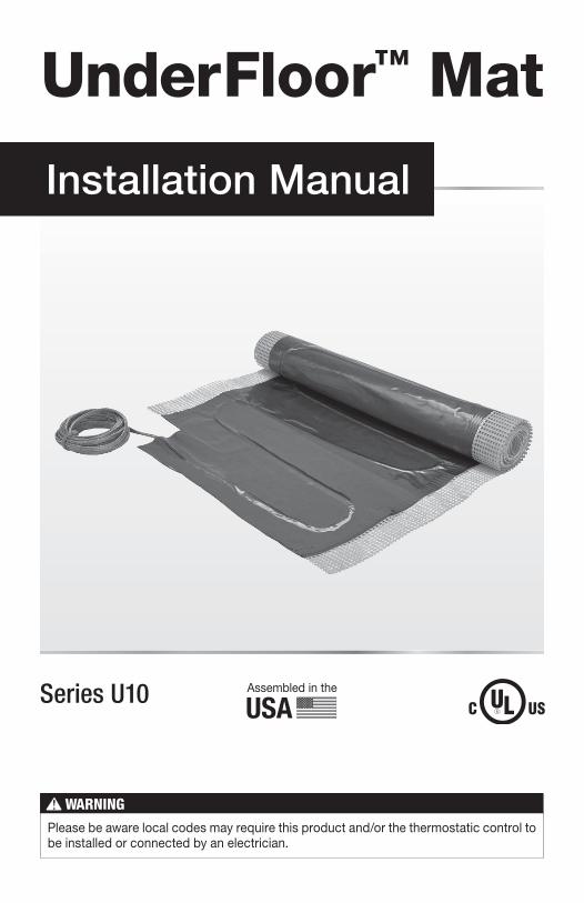
Assembled in the
USASeries U10
Installation Manual
UnderFloor™ Mat
Please be aware local codes may require this product and/or the thermostatic control to be installed or connected by an electrician.
IOM-WR-UF 1528 2 of 24
Read this Manual BEFORE using this equipment.
Failure to read and follow all safety and use information can result in death, serious personal injury, property damage, or damage to the equipment.
Keep this Manual for future reference.
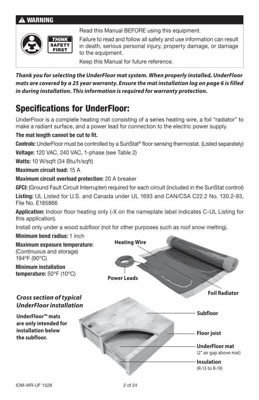
Specifications for UnderFloor:UnderFloor is a complete heating mat consisting of a series heating wire, a foil “radiator” to make a radiant surface, and a power lead for connection to the electric power supply.
The mat length cannot be cut to fit.
Controls: UnderFloor must be controlled by a SunStat® floor sensing thermostat. (Listed separately)
Voltage: 120 VAC, 240 VAC, 1-phase (see Table 2)
Watts: 10 W/sqft (34 Btu/h/sqft)
Maximum circuit load: 15 A
Maximum circuit overload protection: 20 A breaker
GFCI: (Ground Fault Circuit Interrupter) required for each circuit (included in the SunStat control)
Listing: UL Listed for U.S. and Canada under UL 1693 and CAN/CSA C22.2 No. 130.2-93, File No. E185866
Application: Indoor floor heating only (-X on the nameplate label indicates C-UL Listing for this application).
Install only under a wood subfloor (not for other purposes such as roof snow melting).
Minimum bend radius: 1 inch
Maximum exposure temperature: (Continuous and storage) 194ºF (90ºC)
Minimum installation temperature: 50ºF (10ºC)
Thank you for selecting the UnderFloor mat system. When properly installed, UnderFloor mats are covered by a 25 year warranty. Ensure the mat installation log on page 6 is filled in during installation. This information is required for warranty protection.
Cross section of typical UnderFloor installation
UnderFloor mat (2” air gap above mat)
Insulation(R-13 to R-19)
Floor joist
Subfloor
Foil Radiator
Heating Wire
Power Leads
UnderFloor™ mats are only intended for installation below the subfloor.

3 of 24 © 2015 Watts Water Technologies
Skill LevelInstallation must be performed by qualified persons, in accordance with local codes, ANSI/NFPA 70 (NEC Article 424) and CEC Part 1 Section 62 where applicable. Prior to installation please consult the local codes in order to understand what is acceptable. To the extent this information is not consistent with local codes, the local codes should be followed. However, electrical wiring is required from a circuit breaker or other electrical circuit to the control. It is recommended that an electrician perform these installation steps. Please be aware local codes may require this product and/or the control to be installed by an electrician.
Expected floor temperatureHeating performance is never guaranteed. The floor temperature attainable is dependent on how well the floor is insulated as well as the insulating value of the flooring materials. It also is dependent on the temperature of the floor before start up and how well the joist space is sealed against thermal leakage. Insulation is required for best performance. Refer to Phase 5 for important insulation considerations.
If the joist space is sealed against air leakage, exterior rim joists are insulated, and the underneath side of the UnderFloor is insulated per this manual, most floors can be heated up to 15°F warmer than they would otherwise be. Due to the insulation value of carpet, carpeted floors may not achieve the same temperature rise.
Important Safety Information
This is a safety-alert symbol. The safety alert symbol is shown alone or used with a signal word (DANGER, WARNING, or CAUTION), a pictorial and/or a safety message to identify hazards.
When you see this symbol alone or with a signal word on your equipment or in this Manual, be alert to the potential for death or serious personal injury.
This pictorial alerts you to electricity, electrocution, and shock hazards.
This symbol identifies hazards which, if not avoided, could result in death or serious injury.
This symbol identifies hazards which, if not avoided, could result in minor or moderate injury.
This symbol identifies practices, actions, or failure to act which could result in property damage or damage to the equipment.
Table of ContentsImportant Safety Information .....................3Table 1 ..................................................................4Phase 1 - Preparations ..............................6Table 2 - UnderFloor Mat Sizes .............................6Table 3 - Mat Resistance Log.................................7Table 4 - Floor Sensor Resistance Values ..............8Phase 2 - Electrical Rough-in ....................9Table 5 - Circuit Breakers and Supply Wire ............9
Phase 3 - Mat Installation ........................13Phase 4 - Control Installation ..................17Phase 5 - Install Insulation .......................18Connecting Multiple Mats ........................20Troubleshooting Guide.............................21Warranty ...................................................23
IOM-WR-UF 1528 4 of 24
NEVER install one mat on top of another or overlap the mat onto itself. Doing so will cause dangerous overheating.
NEVER forget to install the floor sensor included with the thermostat.
NEVER remove the nameplate label from the power leads. Make sure it is viewable for inspection later.
NEVER install mat in any walls, or over walls or partitions that extend to the ceiling.
NEVER allow metal objects such as staples, metal pipes, ductwork, or straps to remain in contact with the foil radiator of the mat.
NEVER staple closer than 1/4" from the heating wire.
NEVER install the mat closer than 2" from the subfloor.
NEVER install the mat closer than 8" from the edges of outlet boxes and junction boxes used to mount surface lighting fixtures.
NEVER run mats across joists.
NEVER insulate below the mat with greater than R-19, and no greater than R-11 total on top of the subfloor, including all floor coverings, rugs, and other items placed on top.
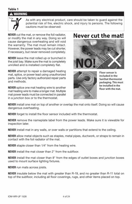
NEVER cut the mat, or remove the foil radiator, or modify the mat in any way. Doing so will cause dangerous overheating and will void the warranty. The mat must remain intact. However, the power leads may be cut shorter, if necessary, but never removed completely.
NEVER leave the mat rolled up or bunched in the joist bay. Make sure the mat is completely unrolled and is installed completely flat.
NEVER attempt to repair a damaged heating mat, splice, or power lead using unauthorized parts. Use only factory authorized repair parts and methods.
NEVER splice one mat heating wire to another mat heating wire to make a longer mat. Multiple mat power leads must be connected in parallel in a junction box or to the thermostat.
Table 1
Never cut the mat!
NO!Floor sensor is included in the SunStat thermostat packaging. This must be installed in the floor with the mat.
As with any electrical product, care should be taken to guard against the potential risk of fire, electric shock, and injury to persons. The following cautions must be observed:
5 of 24 © 2015 Watts Water Technologies
Installation must be performed by qualified personnel, in accordance with local codes and standards. A licensed electrician is recommended.
ALWAYS pay close attention to the voltage and amperage requirements of the breaker, the control, and the mat. For instance, do not supply 240 VAC to 120 VAC mats or damage will result.
ALWAYS make sure all electrical work is done by qualified persons in accordance with local building and electrical codes, Section 62 of the Canadian Electrical Code (CEC) Part I, and the National Electrical Code (NEC), especially Article 424.
ALWAYS use copper only as supply conductors. Do not use aluminum.
ALWAYS seek help if a problem arises. If ever in doubt about the correct installation pro-cedure to follow, or if the product appears to be damaged, the factory must be contacted before proceeding with the installation.
IOM-WR-UF 1528 6 of 24
120 VAC
Mat Size Amperage Draw
Resistance Range (ohms)
12" x 5.5 ft. 0.5 244-30012" x 8 ft. 0.7 169-208
12" x 10.5 ft. 0.9 116-14312" x 13 ft. 1.1 93-11512" x 16 ft. 1.3 77-96
16" x 4 ft. 0.4 256-31316" x 6 ft. 0.7 170-20916" x 8 ft. 0.9 120-147
16" x 9.5 ft. 1.1 96-11816" x 12 ft. 1.3 80–9916" x 14 ft. 1.6 66–8216" x 16 ft. 1.8 61–7516" x 18 ft. 2.0 51–64
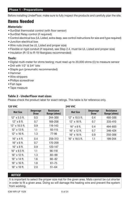
Before installing UnderFloor, make sure to fully inspect the products and carefully plan the site.
Items NeededMaterials:• SunStat thermostat control (with floor sensor)• SunStat Relay control (if required)• Control electrical box (UL Listed, extra deep, see control instructions for size and type required)• Junction electrical box• Wire nuts (must be UL Listed and proper size)• Flexible or rigid conduit (if required, see Step 2.4, must be UL Listed and proper size)• Insulation (R-13 to R-19 fiberglass recommended)
Tools:• Digital multi-meter for ohms testing; must read up to 20,000 ohms (Ω) to measure sensor• Drill with 1/2" & 3/4" bits• Staple gun (pneumatic recommended)• Hammer• Wire strippers• Phillips screwdriver• Fish tape• Tape measure
240 VAC
Mat Size Amperage Draw
Resistance Range (ohms)
12" x 10.5 ft. 0.4 480-58812" x 16 ft. 0.7 335-410
16" x 8 ft. 0.4 494-60516" x 12 ft. 0.7 346-42416" x 16 ft. 0.9 250-306
16" x 19.5 ft. 1.1 199-244
It is important to select the proper size mat for the given area. Mats cannot be cut shorter in order to fit a given area. Doing so will damage the heating wire and prevent the system from working.
Phase 1 - Preparations
Table 2 - UnderFloor mat sizesPlease check the product label for exact ratings. This table is for reference only.
7 of 24 © 2015 Watts Water Technologies
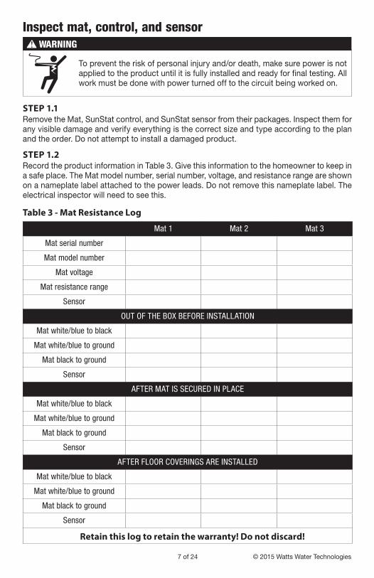
Inspect mat, control, and sensor
To prevent the risk of personal injury and/or death, make sure power is not applied to the product until it is fully installed and ready for final testing. All work must be done with power turned off to the circuit being worked on.
STEP 1.1Remove the Mat, SunStat control, and SunStat sensor from their packages. Inspect them for any visible damage and verify everything is the correct size and type according to the plan and the order. Do not attempt to install a damaged product.
STEP 1.2 Record the product information in Table 3. Give this information to the homeowner to keep in a safe place. The Mat model number, serial number, voltage, and resistance range are shown on a nameplate label attached to the power leads. Do not remove this nameplate label. The electrical inspector will need to see this.
Mat 1 Mat 2 Mat 3
Mat serial number
Mat model number
Mat voltage
Mat resistance range
Sensor
OUT OF THE BOX BEFORE INSTALLATION
Mat white/blue to black
Mat white/blue to ground
Mat black to ground
Sensor
AFTER MAT IS SECURED IN PLACE
Mat white/blue to black
Mat white/blue to ground
Mat black to ground
Sensor
AFTER FLOOR COVERINGS ARE INSTALLED
Mat white/blue to black
Mat white/blue to ground
Mat black to ground
Sensor
Retain this log to retain the warranty! Do not discard!
Table 3 - Mat Resistance Log
IOM-WR-UF 1528 8 of 24
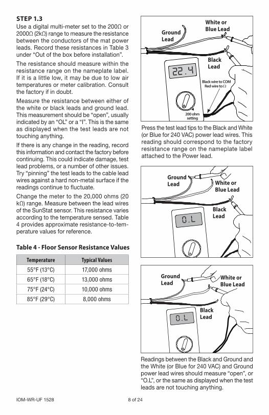
STEP 1.3 Use a digital multi-meter set to the 200Ω or 2000Ω (2kΩ) range to measure the resistance between the conductors of the mat power leads. Record these resistances in Table 3 under “Out of the box before installation”.
The resistance should measure within the resistance range on the nameplate label. If it is a little low, it may be due to low air temperatures or meter calibration. Consult the factory if in doubt.
Measure the resistance between either of the white or black leads and ground lead. This measurement should be “open”, usually indicated by an “OL” or a “I”. This is the same as displayed when the test leads are not touching anything.
If there is any change in the reading, record this information and contact the factory before continuing. This could indicate damage, test lead problems, or a number of other issues. Try “pinning” the test leads to the cable lead wires against a hard non-metal surface if the readings continue to fluctuate.
Change the meter to the 20,000 ohms (20 kΩ) range. Measure between the lead wires of the SunStat sensor. This resistance varies according to the temperature sensed. Table 4 provides approximate resistance-to-tem-perature values for reference.
Black Lead
White or Blue Lead
Ground Lead
Black Lead
White or Blue Lead
Ground Lead
Black Lead
White or Blue LeadGround
Lead
200 ohm setting
Black wire to COMRed wire to Ω
Temperature Typical Values
55°F (13°C) 17,000 ohms
65°F (18°C) 13,000 ohms
75°F (24°C) 10,000 ohms
85°F (29°C) 8,000 ohms
Table 4 - Floor Sensor Resistance Values
Readings between the Black and Ground and the White (or Blue for 240 VAC) and Ground power lead wires should measure “open”, or “O.L”, or the same as displayed when the test leads are not touching anything.
Press the test lead tips to the Black and White (or Blue for 240 VAC) power lead wires. This reading should correspond to the factory resistance range on the nameplate label attached to the Power lead.
9 of 24 © 2015 Watts Water Technologies
Phase 2 - Electrical Rough-in
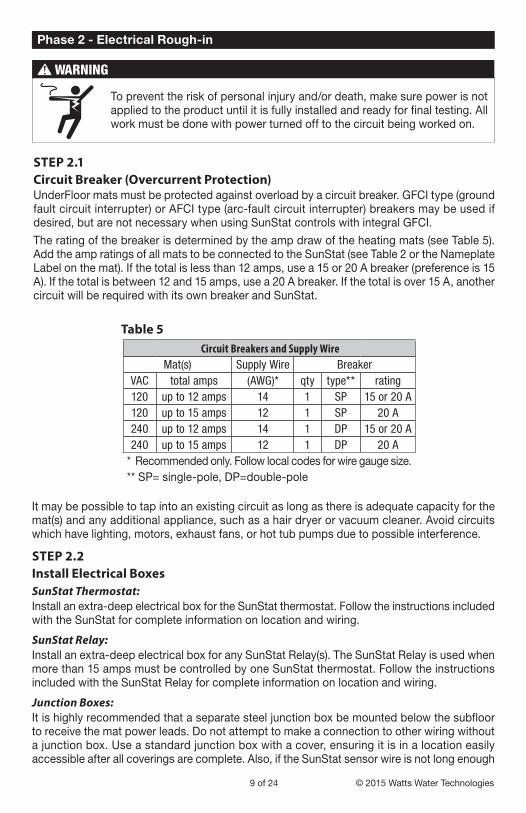
STEP 2.1Circuit Breaker (Overcurrent Protection) UnderFloor mats must be protected against overload by a circuit breaker. GFCI type (ground fault circuit interrupter) or AFCI type (arc-fault circuit interrupter) breakers may be used if desired, but are not necessary when using SunStat controls with integral GFCI.
The rating of the breaker is determined by the amp draw of the heating mats (see Table 5). Add the amp ratings of all mats to be connected to the SunStat (see Table 2 or the Nameplate Label on the mat). If the total is less than 12 amps, use a 15 or 20 A breaker (preference is 15 A). If the total is between 12 and 15 amps, use a 20 A breaker. If the total is over 15 A, another circuit will be required with its own breaker and SunStat.
To prevent the risk of personal injury and/or death, make sure power is not applied to the product until it is fully installed and ready for final testing. All work must be done with power turned off to the circuit being worked on.
Circuit Breakers and Supply WireMat(s) Supply Wire Breaker
VAC total amps (AWG)* qty type** rating120 up to 12 amps 14 1 SP 15 or 20 A120 up to 15 amps 12 1 SP 20 A240 up to 12 amps 14 1 DP 15 or 20 A240 up to 15 amps 12 1 DP 20 A
* Recommended only. Follow local codes for wire gauge size.** SP= single-pole, DP=double-pole
Table 5
It may be possible to tap into an existing circuit as long as there is adequate capacity for the mat(s) and any additional appliance, such as a hair dryer or vacuum cleaner. Avoid circuits which have lighting, motors, exhaust fans, or hot tub pumps due to possible interference.
STEP 2.2Install Electrical Boxes SunStat Thermostat: Install an extra-deep electrical box for the SunStat thermostat. Follow the instructions included with the SunStat for complete information on location and wiring.
SunStat Relay: Install an extra-deep electrical box for any SunStat Relay(s). The SunStat Relay is used when more than 15 amps must be controlled by one SunStat thermostat. Follow the instructions included with the SunStat Relay for complete information on location and wiring.
Junction Boxes:It is highly recommended that a separate steel junction box be mounted below the subfloor to receive the mat power leads. Do not attempt to make a connection to other wiring without a junction box. Use a standard junction box with a cover, ensuring it is in a location easily accessible after all coverings are complete. Also, if the SunStat sensor wire is not long enough

IOM-WR-UF 1528 10 of 24
to reach the SunStat directly, it may be extended. A junction box may be required by local code to make this connection. Follow the installation instructions included with the SunStat for details.
For construction with an existing wall or where the wall is covered, cut the necessary openings to mount the electrical boxes listed above. Wait to install the boxes until all wiring is fed into these locations to make it easier to pull the wire.
Suspended or unfinished ceilings below the mats allow for installation of junction boxes in the joist bays.
Drywall ceilings below the mats will require access doors or cover plates if there are joist bay junction boxes. An alternative is to install junction boxes with a cover plate in the space above.
STEP 2.3 Bottom Plate WorkDrill a hole up through the wall bottom plate to route the power wiring from the thermostat control box to the mats below the floor.
STEP 2.4Install Power Lead ConduitThe shielded power lead can be installed with or without electrical conduit depending on code requirements. Conduit is recommended for added protection against nails or screws. Remove one of the knockouts in the electrical box to route the power lead. If conduit is not required by code, install a wire collar to secure the power leads where they enter the box. If conduit is required, install 1/2" or 3/4" conduit.
STEP 2.5 Rough-in WiringInstall appropriate 12 or 14 AWG electrical wire from the circuit breaker or branch circuit source to the SunStat electrical box following all codes and then to the junction box below the floor for the mat leads. Leave 6"–8" of extra wire at the control box and junction box. Refer to the wiring diagrams in the Appendix for assistance.
If SunStat Relay(s) are used, feed appropriate wire between the SunStat Relay(s) and the SunStat thermostat. See SunStat Relay instructions for details of wire size and type.
11 of 24 © 2015 Watts Water Technologies
STEP 2.6 Install SunStat SensorA floor sensor comes with the SunStat thermostat and must be installed correctly to control the floor temperature. Remember to locate the sensor in a floor where a mat is located. The following are recommended methods for installing the sensor. Other equivalent methods may be used.
Before installing the sensor, make sure to test it with an ohmmeter. See Phase 1.
Method 1. Since a sensor may be difficult to install in some existing floors, the sensor may be placed under the subfloor. However, keep in mind that the temperature the sensor gives will not be a true floor surface temperature and the floor-sensing control may need to be adjusted accordingly.
Drill a hole through the bottom plate of the wall to route the sensor wire. Feed the sensor wire down from the control box through the floor. (A fish-tape may need to be used in order to do this.)
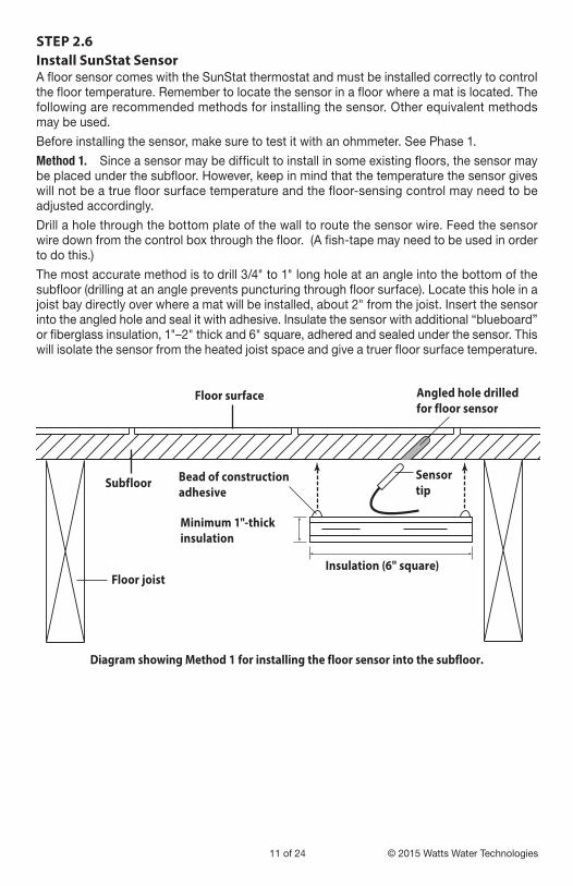
The most accurate method is to drill 3/4" to 1" long hole at an angle into the bottom of the subfloor (drilling at an angle prevents puncturing through floor surface). Locate this hole in a joist bay directly over where a mat will be installed, about 2" from the joist. Insert the sensor into the angled hole and seal it with adhesive. Insulate the sensor with additional “blueboard” or fiberglass insulation, 1"–2" thick and 6" square, adhered and sealed under the sensor. This will isolate the sensor from the heated joist space and give a truer floor surface temperature.
Subfloor
Floor surface
Sensor tip
Bead of constructionadhesive
Angled hole drilled for floor sensor
Floor joist
Minimum 1"-thickinsulation
Insulation (6" square)
Diagram showing Method 1 for installing the floor sensor into the subfloor.

IOM-WR-UF 1528 12 of 24
Method 2. If it is not possible to drill a hole to set the sensor in the subfloor, it may be held flat to the subfloor with a nylon wire clip. Locate the sensor in a joist bay directly over where a mat will be installed, about 2" from the joist. Insulate the sensor with additional “blueboard” or fiberglass insulation, 1" to 2" thick and 6" square. This will help isolate the sensor from the heated joist space.
Method 3: Remove the grout 1/4" to 1/2" deep. Install sensor. Reinstall grout over the sensor and sensor wire.
Method 3. If possible, install the sensor directly into or under the floor covering area.
If the floor surface is tiled, a grout line can be removed and the sensor laid into this grout line.
Drill a hole into the wall behind the baseboard trim area and directly below the control electrical box.
Feed the sensor through the knock-out, down to the hole that was drilled near the floor, and out into the floor above where the heating mat will be installed. Locate the sensor at least 1 ft. from outside walls and near the center of a joist space.
Complete the rest of the installation before covering or regrouting over the sensor.
13 of 24 © 2015 Watts Water Technologies
Phase 3 - Mat Installation
To prevent the risk of personal injury and/or death, make sure power is not applied to the product until it is fully installed and ready for final testing. All work must be done with power turned off to the circuit being worked on.
Do not allow the foil radiator of the mat to be mounted such that it contacts metal objects such as nails, staples, metal pipes, heating ducts, and joist straps.
Keep the mat at least 2" away from recessed fixtures (lights, etc.), ventilation openings, and other openings.
Keep the mat at least 8" away from the edges of outlet boxes and junction boxes used to mount surface lighting fixtures.
Keep the mat at least 6" away from heat-sensitive items such as toilet rings, flexible ducting, and other items rated less than 194°F (90°C). Consult manufacturers of those items.
Do not leave the mat rolled up or bunched up in any way in the joist bay. Doing so will cause dangerous overheating and possible damage. Mats must be installed so that they are completely flat across the joist cavity.
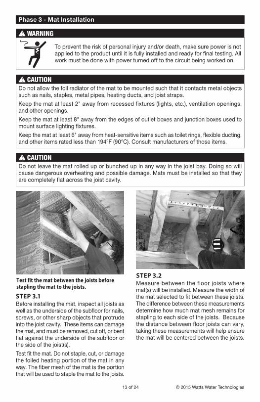
STEP 3.1Before installing the mat, inspect all joists as well as the underside of the subfloor for nails, screws, or other sharp objects that protrude into the joist cavity. These items can damage the mat, and must be removed, cut off, or bent flat against the underside of the subfloor or the side of the joist(s).
Test fit the mat. Do not staple, cut, or damage the foiled heating portion of the mat in any way. The fiber mesh of the mat is the portion that will be used to staple the mat to the joists.
Test fit the mat between the joists before stapling the mat to the joists.
STEP 3.2Measure between the floor joists where mat(s) will be installed. Measure the width of the mat selected to fit between these joists. The difference between these measurements determine how much mat mesh remains for stapling to each side of the joists. Because the distance between floor joists can vary, taking these measurements will help ensure the mat will be centered between the joists.
IOM-WR-UF 1528 14 of 24
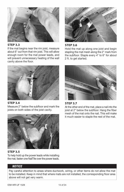
Pay careful attention to areas where ductwork, wiring, or other items do not allow the mat to be installed. Keep in mind that where mats are not installed, the corresponding floor area above will not get very warm.
STEP 3.3If the mat begins near the rim joist, measure about 6" out from that rim joist. This will allow enough room for the mat power leads, and will prevent unnecessary heating of the wall cavity above the floor.
STEP 3.4Measure 2" below the subfloor and mark the joists on both sides of the joist cavity.
STEP 3.5To help hold up the power leads while installing the mat, fasten one NailTite over the power leads.
STEP 3.6Hold the mat up along one joist and begin stapling the mat mesh along the 2" mark from the subfloor. Staple every 4" to 6" for about 2 ft. to get started.
STEP 3.7At the other end of the mat, place a nail into the joist at 2" below the subfloor. Hang the fiber mesh of the mat onto the nail. This will make it much easier to staple the rest of the mat.

15 of 24 © 2015 Watts Water Technologies
STEP 3.9Raise the mat to the other joist and staple the mat mesh 2" below the subfloor.
STEP 3.10Using the same techniques, staple up all other mats.
STEP 3.8Continue stapling the mat mesh at 2" below the subfloor, every 4" to 6". Then remove the nail at the end that held it up.

IOM-WR-UF 1528 16 of 24
STEP 3.11Power Lead InstallationIf you have not already done so, mount a junction box below the subfloor within reach of the mat power leads. Install more than one junction box, if needed, for larger jobs. The junction box must remain accessible in accordance with electrical codes, so consider the location of the junction box carefully should the ceiling be finished after installation of the mat(s).
Route the power leads from the mat(s) to the junction box following all electrical and building codes using conduit and additional electrical boxes where required.
Junction box with multiple sets of mat lead wires, connected in parallel, and connected to the power supply.
For multiple mats, follow all electrical codes concerning “box fill” maximums. Connect the leads in parallel (black-to-black, white-to-white), and not in series.
Connect the mat leads to the power drop from the SunStat thermostat or SunStat Relay.
STEP 3.12Take photographs of the mat installation. This can be very useful later during remodel work to help avoid possible wire damage. Keep the photos with this installation manual and provide to end user upon completion.
17 of 24 © 2015 Watts Water Technologies
STEP 4.1 Install the ControlRead and follow the instructions included with the SunStat thermostat and SunStat Relay for complete connection instructions, requirements, and mounting.
STEP 4.2 Connect the power supply leads, the power drop to the mat junction box, and the floor sensor wire to the SunStat. Follow proper wiring procedures.
STEP 4.3Make any final connections to the circuit breaker or branch circuit source.
STEP 4.4Test the SystemAfter the controls are installed and connected, energize the system briefly to test operation of all components.
Refer to the installation sheets provided with the SunStat for proper setting.
Without floor insulation, the mat will not heat the floor. When the SunStat calls for heat to the mat, the mat will begin to feel warm to the touch within 1 to 2 minutes or so. If this does not occur, recheck the SunStat settings, wiring connections, and power supply.
Phase 4 - Control Installation
CKT#
CKT#
CKT#
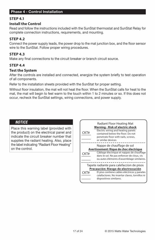
Radiant Floor Heating MatWarning - Risk of electric shock
Electric wiring and heating panels contained below the floor. Do not penetrate floor with nails, screws, or similar devices
Nappe de chauffage de solAvertissement: Rique de choc électrique
Câblage électrique et nappes de chauffage dans le sol. Ne pas enfoncer de clous, vis ou autes éléments d’assemblage similaires.
Tapete radiante para calefaccion de pisosPrecaución: Riesgo de electrocución
El piso contiene cables eléctricos y paneles calafactores. No insertar clavos, tornillos ni dispositivos similares.
Place this warning label (provided with the product) on the electrical panel and indicate the circuit breaker number that supplies the radiant heating. Also, place the label indicating “Radiant Floor Heating” on the control.

IOM-WR-UF 1528 18 of 24
Install R-13 to R-19 fiberglass insulation below the mat. Gently press the insulation up to the mat for best results and secure in place with rods, staples, or other method. A gap between the insulation and mat is acceptable but will not give the best heating results.
Make sure to insulate at the end of all heated joist cavities. Install insulation vertically in these areas to seal the ends of the heated joist areas or, 6" after the mat “stops” in a joist space, push the insulation up tight against the subfloor and staple to the subfloor. This ensures that no heated air can escape from the heated joist space. If this is not done, much heat will “escape” horizontally through band joists, rim joists, exterior walls, and open ends of joist spaces, and the floor will not warm as it should.
Seal openings around pipes, waste lines, ducts, joist blocking, and all other gaps with silicone caulking or urethane foam. The system should now operate as designed. Please leave this instruction manual, SunStat instructions, and copies of photos of the installed heating system with the end user.
Phase 5 - Install Insulation
Insulate ends of joist bays
Insulate outside heated area
UnderFloor mats
Install mats 2" below subfloor
2"
19 of 24 © 2015 Watts Water Technologies
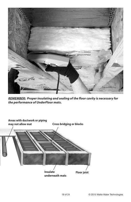
REMEMBER: Proper insulating and sealing of the floor cavity is necessary for the performance of UnderFloor mats.
Cross bridging or blocks
Insulate underneath mats
Areas with ductwork or piping may not allow mat
Floor joist
IOM-WR-UF 1528 20 of 24
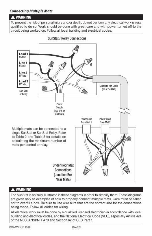
Power LeadFrom Mat 2
Power LeadFrom Mat 1
G
G
Sun Stator Relay
SunStat / Relay Connections
UnderFloor MatConnections
(Junction BoxNear Mats)
PowerSupply
(120 VAC or240 VAC)
Load 1
Line 1
Line 2
Black
Black
White
White
Load 2Standard NM Cable
(12 or 14 AWG)
Connecting Multiple Mats
Multiple mats can be connected to a single SunStat or SunStat Relay. Refer to Table 2 and Table 5 for details on calculating the maximum number of mats per control or relay.
To prevent the risk of personal injury and/or death, do not perform any electrical work unless qualified to do so. Work should be done with great care and with power turned off to the circuit being worked on. Follow all local building and electrical codes.
The SunStat is not fully illustrated in these diagrams in order to simplify them. These diagrams are given only as examples of how to properly connect multiple mats. Care must be taken not to overfill a box. Be sure to use wire nuts that are the correct size for the connections being made. Follow all codes for wiring.
All electrical work must be done by a qualified licensed electrician in accordance with local building and electrical codes, and the National Electrical Code (NEC), especially Article 424 of the NEC, ANSI/NFPA70 and Section 62 of CEC Part 1.
21 of 24 © 2015 Watts Water Technologies
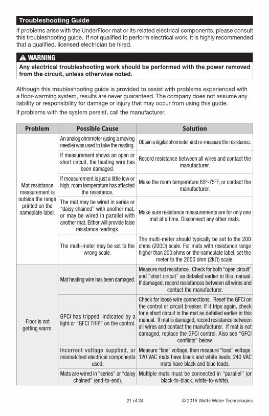
If problems arise with the UnderFloor mat or its related electrical components, please consult this troubleshooting guide. If not qualified to perform electrical work, it is highly recommended that a qualified, licensed electrician be hired.
Problem Possible Cause Solution
Mat resistance measurement is
outside the range printed on the
nameplate label.
An analog ohmmeter (using a moving needle) was used to take the reading. Obtain a digital ohmmeter and re-measure the resistance.
If measurement shows an open or short circuit, the heating wire has
been damaged.
Record resistance between all wires and contact the manufacturer.
If measurement is just a little low or high, room temperature has affected
the resistance.
Make the room temperature 65º-75ºF, or contact the manufacturer.
The mat may be wired in series or “daisy chained” with another mat, or may be wired in parallel with another mat. Either will provide false
resistance readings.
Make sure resistance measurements are for only one mat at a time. Disconnect any other mats.
The multi-meter may be set to the wrong scale.
The multi-meter should typically be set to the 200 ohms (200Ω) scale. For mats with resistance range higher than 200 ohms on the nameplate label, set the
meter to the 2000 ohm (2kΩ) scale.
Floor is not getting warm.
Mat heating wire has been damaged.
Measure mat resistance. Check for both “open circuit” and “short circuit” as detailed earlier in this manual. If damaged, record resistances between all wires and
contact the manufacturer.
GFCI has tripped, indicated by a light or “GFCI TRIP” on the control.
Check for loose wire connections. Reset the GFCI on the control or circuit breaker. If it trips again, check for a short circuit in the mat as detailed earlier in this manual. If mat is damaged, record resistance between all wires and contact the manufacturer. If mat is not damaged, replace the GFCI control. Also see “GFCI
conflicts” below.
Incorrect voltage supplied, or mismatched electrical components
used.
Measure “line” voltage, then measure “load” voltage. 120 VAC mats have black and white leads. 240 VAC
mats have black and blue leads.
Mats are wired in “series” or “daisy chained” (end-to-end).
Multiple mats must be connected in “parallel” (or black-to-black, white-to-white).
Troubleshooting Guide
Any electrical troubleshooting work should be performed with the power removed from the circuit, unless otherwise noted.
Although this troubleshooting guide is provided to assist with problems experienced with a floor-warming system, results are never guaranteed. The company does not assume any liability or responsibility for damage or injury that may occur from using this guide.
If problems with the system persist, call the manufacturer.

IOM-WR-UF 1528 22 of 24
Problem Possible Cause Solution
Floor heats continuously.
Incorrect wiring. The control was “bypassed” when it was wired to
the power supply.
Make sure wiring connections are correct. Consult the wiring diagram on the back of the control, the instructions that came with the control, or the wiring
diagrams in this manual.
Defective control. Return control to dealer for replacement.
Control is not working correctly.
If a programmable control, the programming may be incorrect.
Carefully read and follow control programming instructions.
Incorrect voltage supplied, or mismatched
components used.
Test voltage, verify parts. See “Incorrect voltage supplied” above.
Floor sensor is not wired properly, or is not working properly.
Make sure only one floor sensor is connected to the control.
Loose connection(s) on line side and/or load side of control.
Remove and reinstall the wire nuts at each connection. Make sure the wire nuts are tight.
Check all connections back to the breaker.
Control is not working at all.
No power is supplied.Check circuit breaker. Measure voltage at the control (Line1 to Line2). Check all connections between
breaker and control.
Defective control. Return control to dealer for replacement.
GFCI conflicts and false-trips.
An electric motor or a ballasted light source is sharing the circuit with
the control.
Electric motors and other electrical devices can cause a GFCI to false-trip. Run a dedicated circuit to the floor-warming system or select a different branch circuit.
WARNING: This product contains chemicals known to the State of California to cause cancer and birth defects or other reproductive harm. For more information: Watts.com/prop65
23 of 24 © 2015 Watts Water Technologies
Electric Floor-warming Products 25-year Limited WarrantySunTouch and Watts Radiant (the Companies) warrant their respective electric floor heating mats and cables (the Products) to be free from defects in materials and workmanship for twenty-five (25) years from the date of manufacture. Thermostats and controls sold by the Companies are warranted, parts and materials, for two (2) years from the date of purchase. The sole remedy for controls is product replacement. This warranty is only provided to customers who purchase the Products from authorized resellers, and is transferable to subsequent owners of properties where the Products are initially installed.
Under this Limited Warranty, the Companies will provide the following:If the Product is determined by the Companies to be defective in materials and workmanship, and has not been damaged as a result of abuse, misapplication or modification, the Companies will refund all or part of the manufacturer’s published list price of the Product at the time of purchase in accordance with the following: 100% for the first ten (10) years, then prorated on a diminishing 25-year scale for the remaining warranty period.
For example: (1) Product found defective in the 5th year will receive the
full manufacturer’s published list price of the Product at the time of purchase;
(2) Product found defective in the 15th year, with 10 years remaining in the warranty period, will receive 10/25ths of the manufacturer’s published list price of the Product at the time of purchase.
In order to make a claim, you must:(a) Provide the Company with sufficient details relating to
the nature of the defect, the installation, the history of operation, and any repairs that may have been made.
(b) At the Company’s discretion and at the owner’s expense, ship the Product to the Company or the Company’s local representative or distributor.
(c) Provide proof that the Product was installed in accordance with the applicable Product Installation Manual and any special written design or installation guidelines by the Companies for this project.
(d) Provide proof that the Product was installed in accordance with the National Electrical Code (NEC) or the Canadian Electrical Code (CEC), and all applicable local building and electrical codes.
(e) Provide a retail sales receipt or proof of purchase.
The following are not covered by this Limited Warranty:(a) Any incidental or consequential damage, including
inconvenience, loss of time or loss of income.(b) Any labor or materials required to repair or replace the
Product or control, not authorized in writing by the Company.
(c) Any labor or materials required to remove, repair or replace flooring materials.
(d) Any freight or delivery costs related to the Product, the control, or any related flooring or electrical products.
The Companies assume no responsibility under this warranty for any damage to the Product caused by any trades people, visitors on the job site, or damage caused as a result of post-installation work. The staff at the Company is available to answer any questions regarding the proper installation or application of the Product at this toll-free phone number: 800-276-2419. If you are ever in doubt about the correct installation procedure to follow, or if the Product appears to be damaged, you must call us before proceeding with the installation, or proposed repair.
THE COMPANIES DISCLAIM ANY WARRANTY NOT PROVIDED HEREIN, INCLUDING ANY IMPLIED WARRANTY OF MERCHANTABILITY OR IMPLIED WARRANTY OF FITNESS FOR A PARTICULAR PURPOSE. THE COMPANIES FURTHER DISCLAIM ANY RESPONSIBILITY FOR SPECIAL, INDIRECT, SECONDARY, INCIDENTAL, OR CONSEQUENTIAL DAMAGES ARISING FROM OWNERSHIP OR USE OF THIS PRODUCT, INCLUDING INCONVENIENCE OR LOSS OF USE. THERE ARE NO WARRANTIES WHICH EXTEND BEYOND THE FACE OF THIS DOCUMENT. NO AGENT OR REPRESENTATIVE OF THE COMPANIES HAS ANY AUTHORITY TO EXTEND OR MODIFY THIS WARRANTY UNLESS SUCH EXTENSION OR MODIFICATION IS MADE IN WRITING BY A CORPORATE OFFICER.DUE TO DIFFERENCES IN BUILDING AND FLOOR INSULATION, CLIMATE, AND FLOOR COVERINGS, THE COMPANIES MAKE NO REPRESENTATION THAT THE FLOOR TEMPERATURE WILL ACHIEVE ANY PARTICULAR TEMPERATURE, OR TEMPERATURE RISE. UL® STANDARD LISTING REQUIREMENTS LIMIT THE HEAT OUTPUT OF REGULAR MATS AND CABLES TO 15 WATTS PER SQUARE FOOT DEPENDING ON CABLE INSTALL SPACING, AND UNDERFLOOR MATS TO 10 WATTS PER SQUARE FOOT, AND AS SUCH, USERS MAY OR MAY NOT BE SATISFIED WITH THE FLOOR WARMTH THAT IS PRODUCED. THE COMPANIES DO WARRANT THAT ALL PRODUCTS WILL PRODUCE THE RATED OUTPUT LISTED ON THE PRODUCT NAMEPLATE, WHEN OPERATED AT THE RATED VOLTAGE.Some states do not allow the exclusion or limitation of incidental or consequential damages and some states do not allow limitations on how long implied warranties may last. Therefore, the above limitations or exclusions may not apply to you. This warranty gives you specific legal rights and you may also have other rights, which vary from state to state. SO FAR AS IS CONSISTENT WITH APPLICABLE STATE LAW, ANY IMPLIED WARRANTIES THAT MAY NOT BE DISCLAIMED, INCLUDING IMPLIED WARRANTIES OF MERCHANTABILITY OR FITNESS FOR A PARTICULAR PURPOSE ARE LIMITED IN DURATION TO TWENTY-FIVE YEARS FROM THE DATE OF MANUFACTURE.
Terms and ConditionsShipping Discrepancies: Incoming materials should be inven-toried for completeness and for possible shipping damage. Any visible damages or shortages must be noted prior to accepting the material. Once the receiving personnel accept the material on their dock, they have relieved the freight company of any responsibility. Any discrepancy concerning type or quantity of material shipped, must be brought to the attention of the Companies within 15 days of the shipping date entered on the packing slip for the order.Return Policy: The Companies items may be returned within one year from the date of purchase, if they are not damaged or used. There will be a 15% restock charge applied to items returned due to overstock or customer order error. All returned items must be in new condition. Products, controls or other parts that have a quality defect will be replaced (not credited) at no charge to the customer. If an item is shipped in error, there will be no restocking charge. All items returned, for replacement, credit or repair, must have a Returned Goods Authorization (RGA) number, or they will not be accepted. Please call our order desk for an RGA number. Products older than one year are excluded from these terms and conditions and may not be returned. No returns will be accepted for the Custom TapeMat product.Products that have been damaged, or Products that have been cut, may not be returned. This includes Products that have had mortar or concrete materials applied to them. These Products cannot be repaired and cannot be resold; therefore, we cannot accept them.Effective: APRIL 1, 2006. This warranty applies to all Products purchased after this date.
IOM-WR-UF 1528 EDP#81009042 ©2015 Watts Water Technologies
Affiliations:
The SunTouch and Watts Radiant manufacturing facility’s Quality System is an ISO 9001:2008 registered facility through LRQA.
8 4 0 2 1 3 1 1 3 3 2 2
SunTouch Customer SupportUSA Toll-free: (888) 432-8932
USA Fax: (417) 831-4067Canada Toll-free: (888) 208-8927
Canada Fax: (905) 332-7068Latin America Tel: (52) 81-1001-8600
Latin America Fax: (52) 81-8000-7091SunTouch.com
Watts Radiant Customer SupportUSA Toll-free: (800) 276-2419
USA Fax: (417) 864-8161WattsRadiant.com
Canada Toll-free: (888) 208-8927Canada Fax: (905) 332-7068
Watts.ca