Embed Size (px)
Citation preview
Underbalanced Drilling
14 May 2015
Agenda
• Drilling overview
• Underbalanced Drilling
– What is it?
– Why to drill UBD?
– Evaluation Criteria
– Equipment
– Well Control
• Case Study
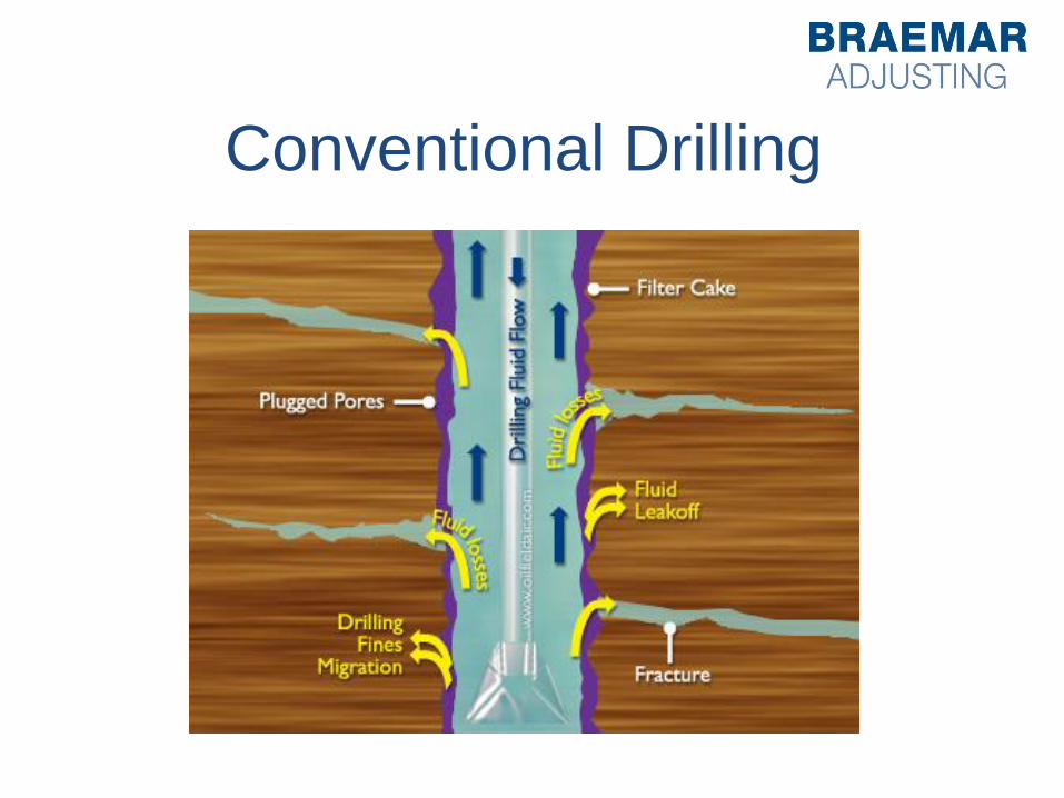
Conventional Drilling
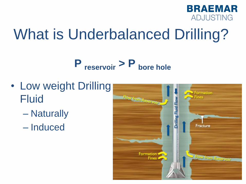
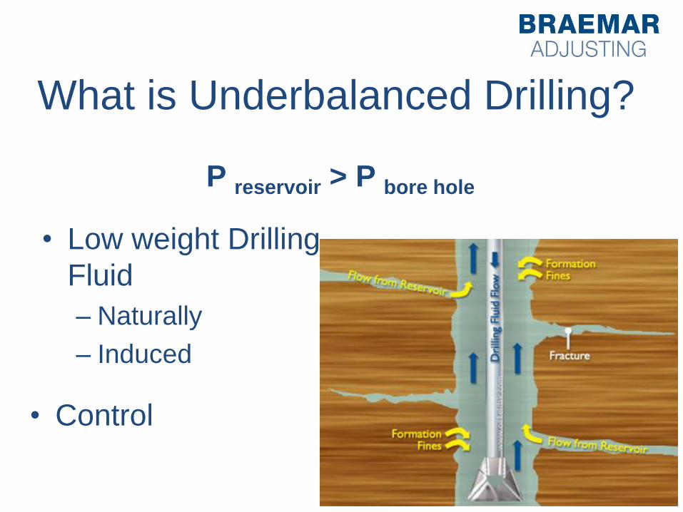
What is Underbalanced Drilling?
• Low weight Drilling
Fluid
– Naturally
– Induced
P reservoir > P bore hole
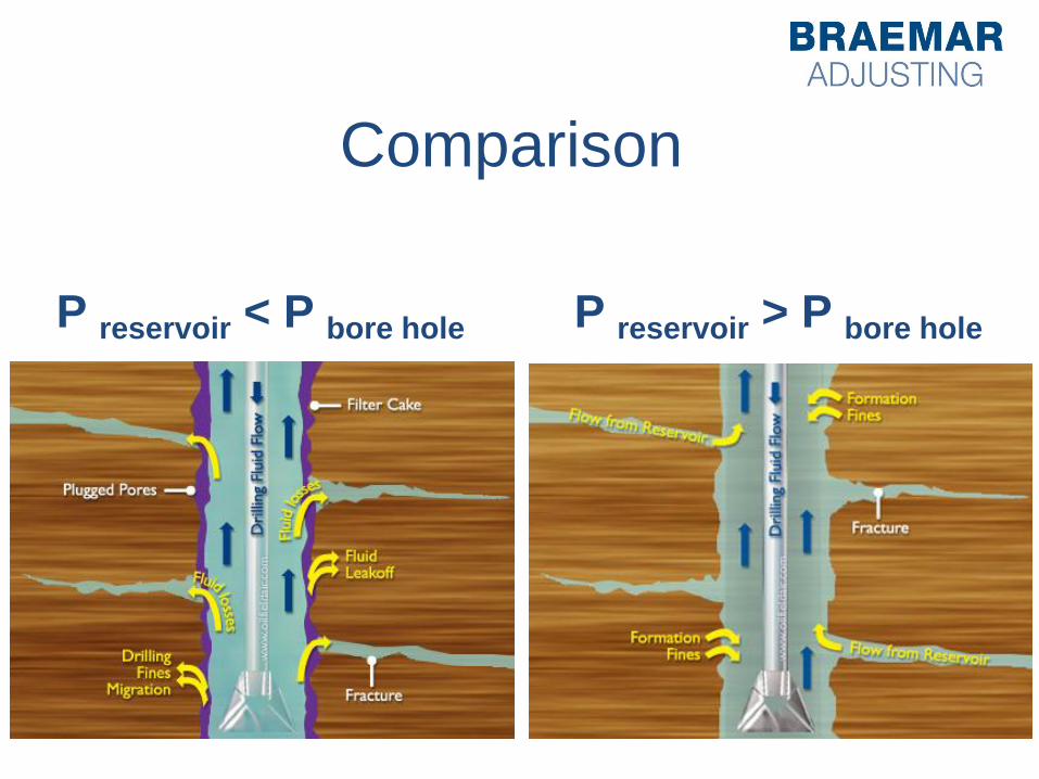
Comparison
P reservoir > P bore hole P reservoir < P bore hole
What is Underbalanced Drilling?
• Low weight Drilling
Fluid
– Naturally
– Induced
P reservoir > P bore hole
• Control
Why to Drill Underbalanced?
• To maximize hydrocarbon recovery
– Reduce formation damage
– Produce earlier
– Increase reservoir knowledge
– Enhanced oil recovery
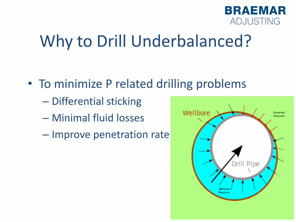
Why to Drill Underbalanced?
• To minimize P related drilling problems
– Differential sticking
– Minimal fluid losses
– Improve penetration rate
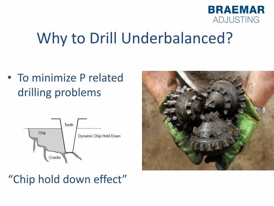
Why to Drill Underbalanced?
“Chip hold down effect”
• To minimize P related drilling problems
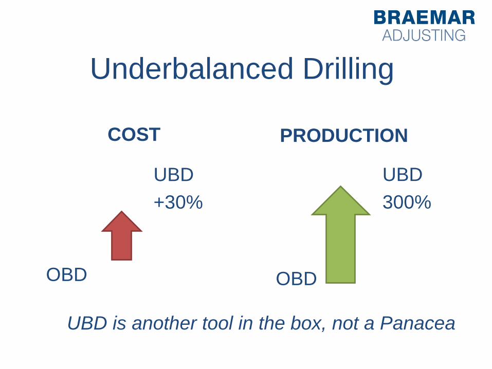
Underbalanced Drilling
COST
UBD
+30%
OBD
PRODUCTION
OBD
UBD
300%
UBD is another tool in the box, not a Panacea
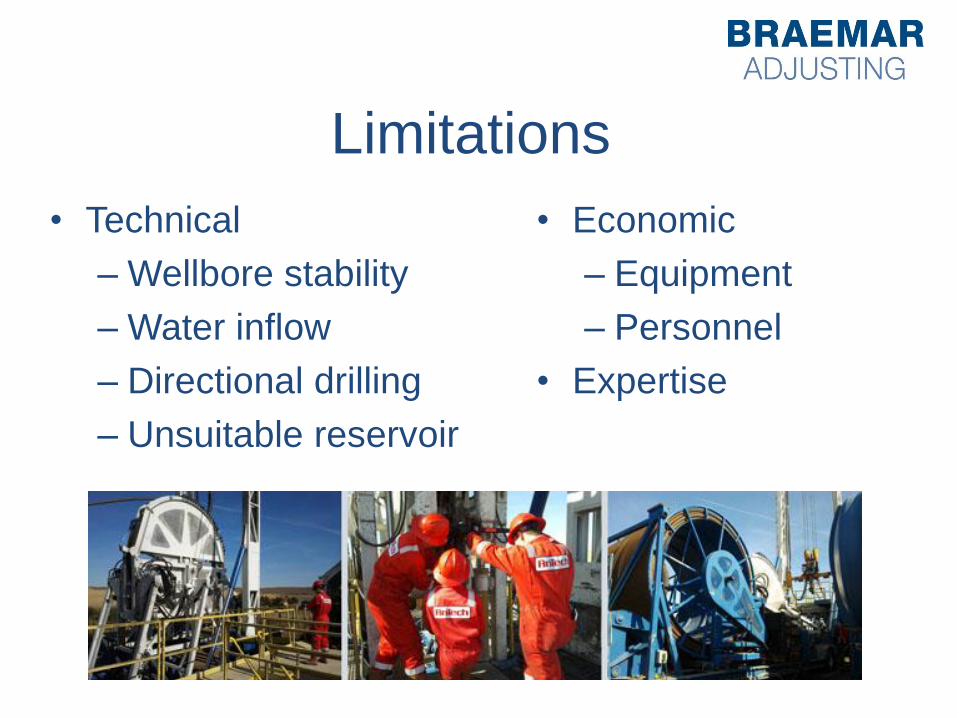
Limitations
• Technical
– Wellbore stability
– Water inflow
– Directional drilling
– Unsuitable reservoir
• Economic
– Equipment
– Personnel
• Expertise
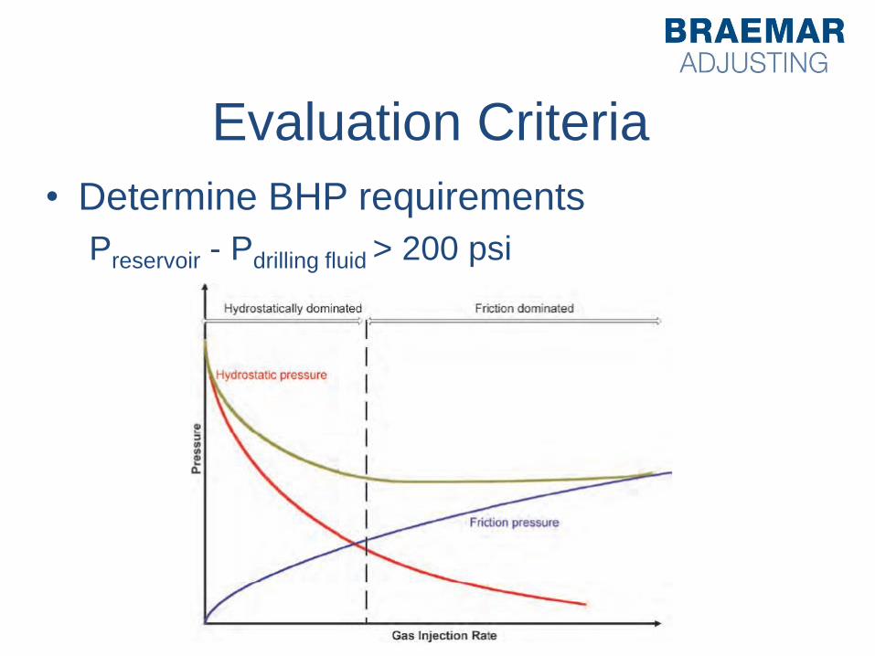
Evaluation Criteria
• Determine BHP requirements
Preservoir - Pdrilling fluid > 200 psi
Evaluation Criteria
• Identify the drilling fluid system
– Gas-air
– Gasified Fluid
– Stable Foam
– Drilling Fluid
Evaluation Criteria
• Identify the drilling fluid system
– Gas-air
– Gasified Fluid
– Stable Foam
– Drilling Fluid
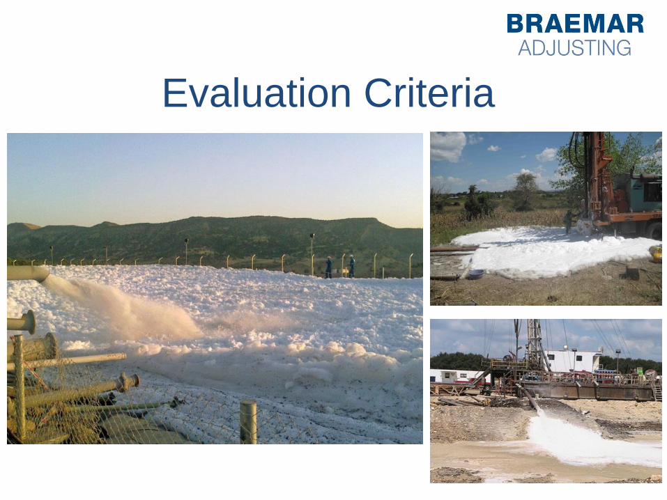
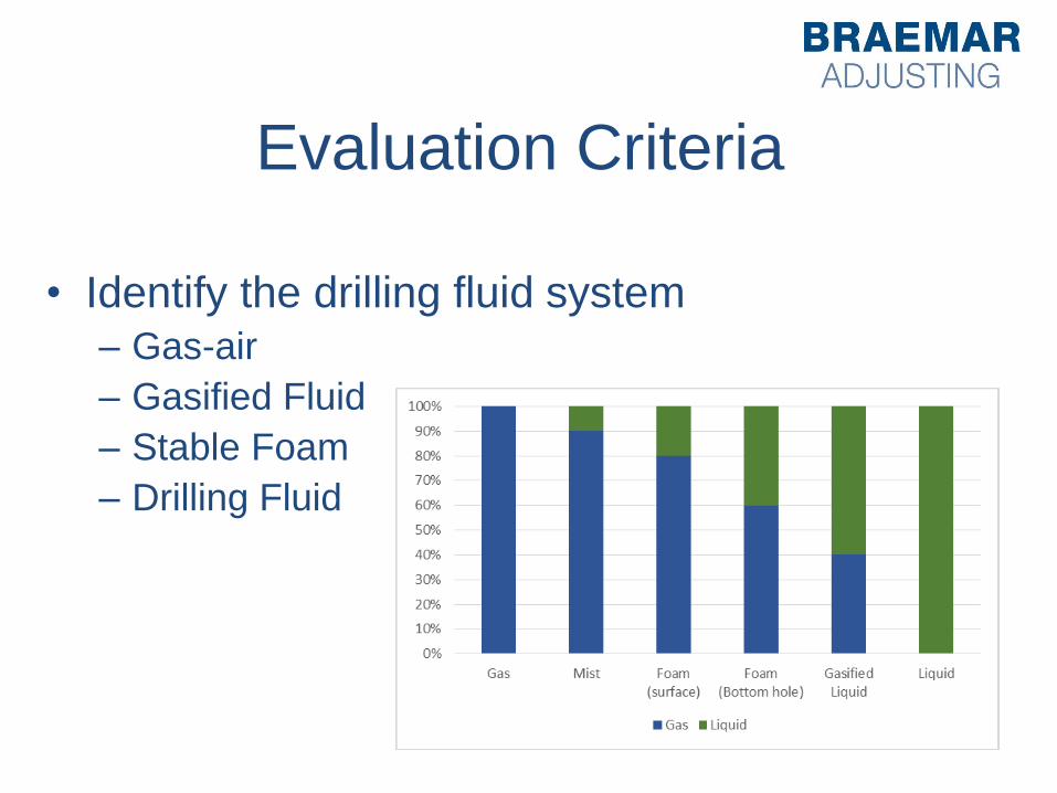
Evaluation Criteria
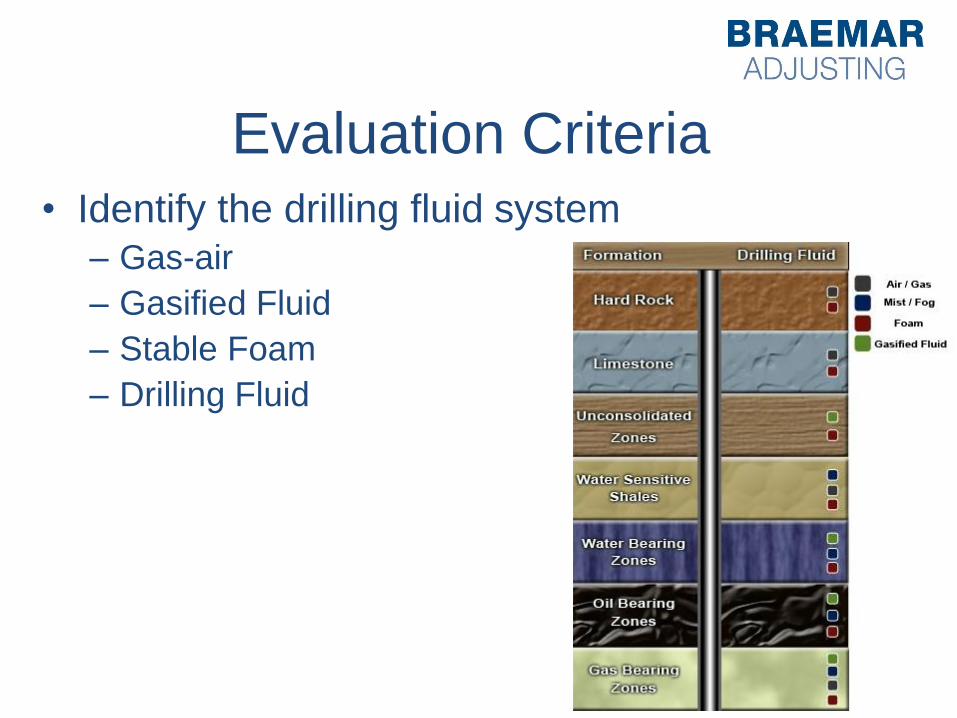
Evaluation Criteria
• Identify the drilling fluid system
– Gas-air
– Gasified Fluid
– Stable Foam
– Drilling Fluid
Evaluation Criteria
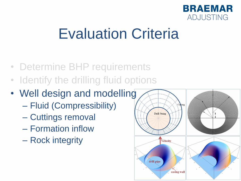
• Determine BHP requirements
• Identify the drilling fluid options
• Well design and modelling
– Fluid (Compressibility)
– Cuttings removal
– Formation inflow
– Rock integrity
Evaluation Criteria
• Determine BHP requirements
• Identify the drilling fluid system
• Well design and modelling
• Select the surface equipment
– Productivity -> Capacity at surface
Case Study
• On-shore, New Mexico, 20 June 2006
• Spud date 17 May 2006
• Overbalanced drilling until @ 9,471 ft
• Expected formation pressure is 5,000 psi
• Drilling underbalanced 300 psi
• Hydrostatic pressure used was 4,700 psi
• Mud weight: 9.5 ppg, diesel based
Case Study
• Highly permeable formation with large fluid
losses expected
• Objective was to avoid economical losses
due to the loss of drilling fluids and excess
rig time
• Objective to prevent differential sticking of
drill pipe
Case Study
• Drilling system: jointed pipe
• No gas generation equipment because the
chose liquid system: diesel
• Rotating head
• Basic mud gas separation
• Gas production sent to flair
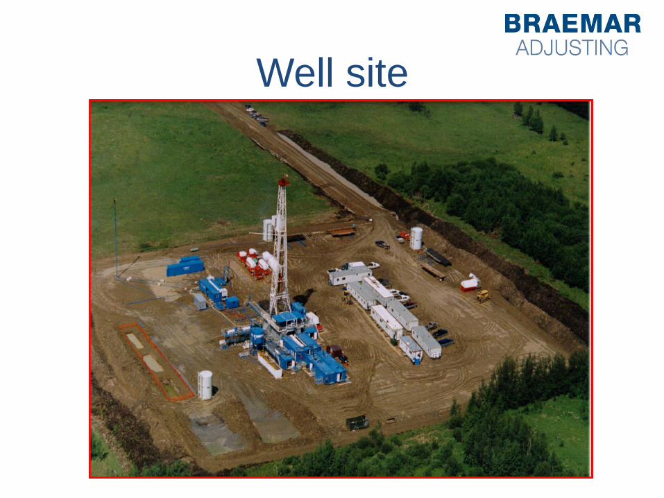
Well site
Surface Equipment
• Drilling System
• Well control equipment
• Gas-generation equipment
• Surface separation equipment
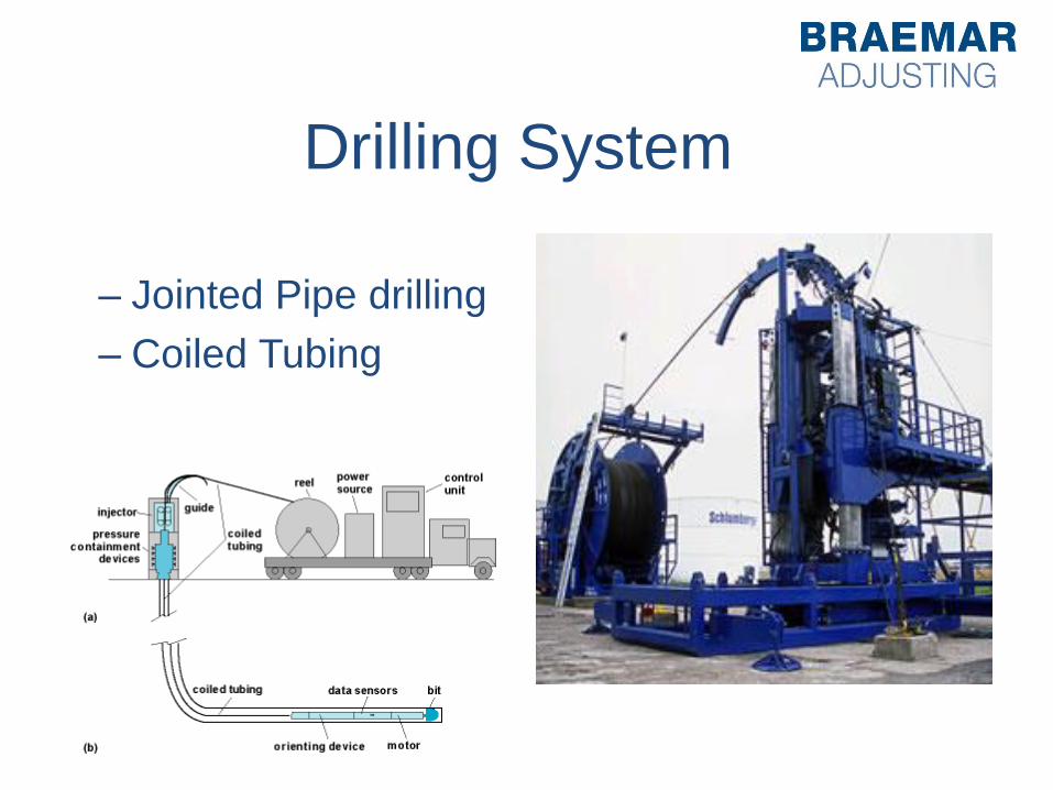
Drilling System
– Jointed Pipe drilling
– Coiled Tubing
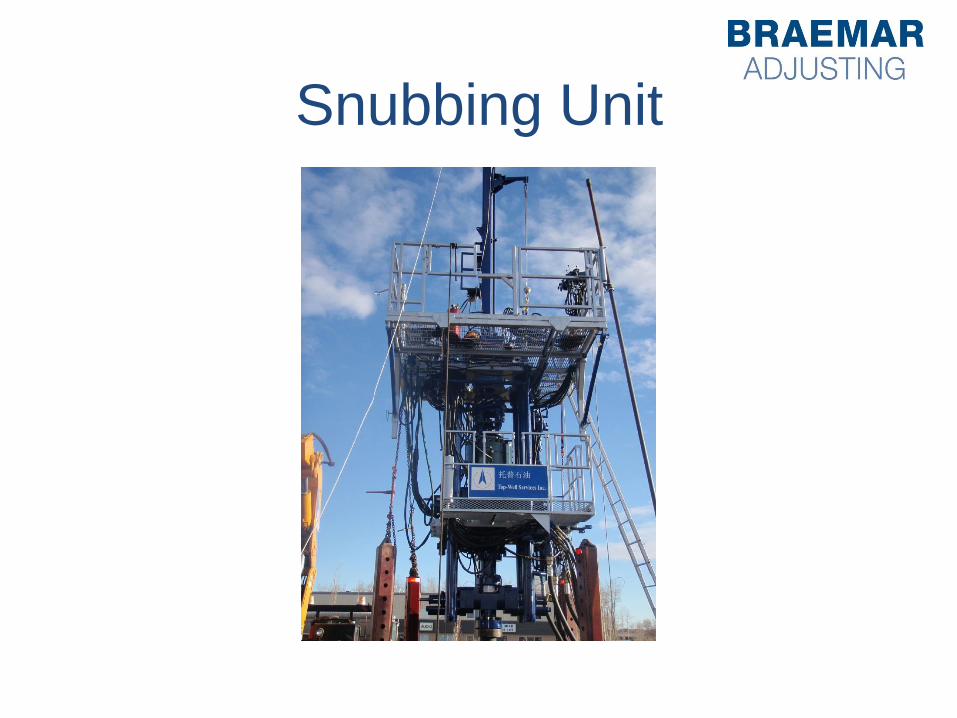
Snubbing Unit
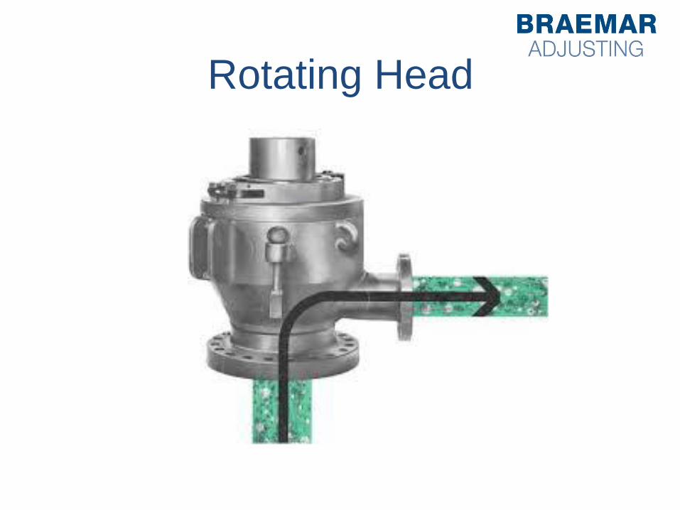
Rotating Head

Well site
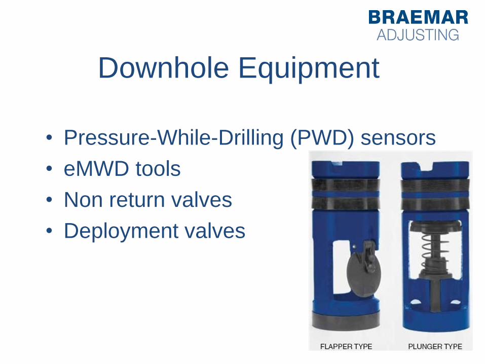
Downhole Equipment
• Pressure-While-Drilling (PWD) sensors
• eMWD tools
• Non return valves
• Deployment valves
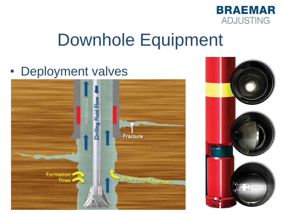
Downhole Equipment
• Deployment valves
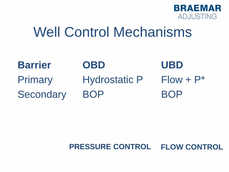
Well Control Mechanisms
Barrier
Primary
Secondary
UBD
Flow + P*
BOP
PRESSURE CONTROL FLOW CONTROL
OBD
Hydrostatic P
BOP
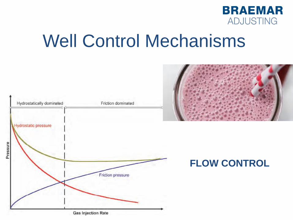
Well Control Mechanisms
FLOW CONTROL

Well Control Mechanisms
PRESSURE CONTROL FLOW CONTROL
OBD
– Hydrostatic
(Dynamic)
– Friction
(Dynamic)
– BOP
UBD
– Hydrostatic (Passive)
– Flow and pressure
control Friction
(Dynamic)
– Choke Pressure
Due Diligence
• Underbalanced
– “… that method of drilling whereby the terrastatic
pressure exceeds the pressure exerted by the
drilling fluid column in the bore of a well.”
• Producing While Drilling
– “… those methods of drilling whereby the
formation fluids are deliberately allowed in the
bore of a Drilling Well and thence removed to the
surface while … Drilling activities are continued
…
Conditions
I. “… a blowout preventer configuration
including one rotating head …”
II. “… any sources of ignition are removed
… from any area … which operations are
being conducted …”
III. “all oil/gas separators … will be placed at
a safe distance from the drilling rig …”
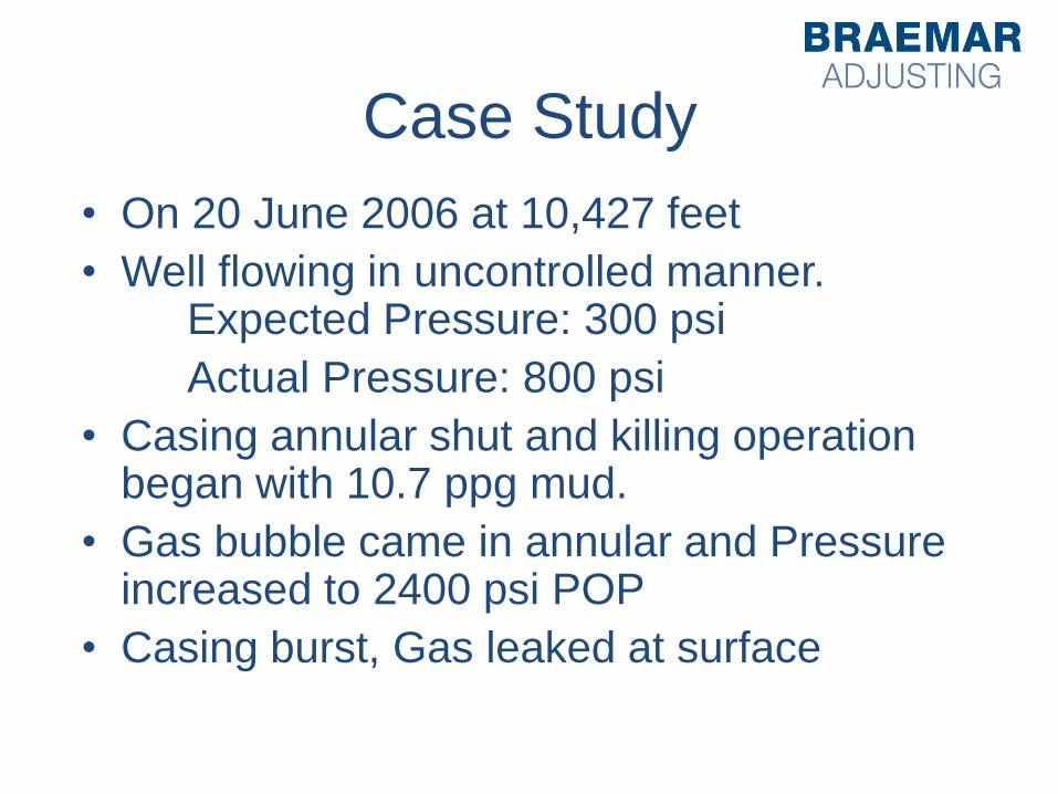
Case Study
• On 20 June 2006 at 10,427 feet
• Well flowing in uncontrolled manner. Expected Pressure: 300 psi
Actual Pressure: 800 psi
• Casing annular shut and killing operation began with 10.7 ppg mud.
• Gas bubble came in annular and Pressure increased to 2400 psi POP
• Casing burst, Gas leaked at surface
Case Study
• Failure on the rotating head caused a gas
build up in the annular.
• Well control: increased drilling fluid to 11.2
ppg
• 25 June 2006 finally killed the well
Case Study
• Remedial measures
– Located the burst section and squeezed
• Remedial Casing 7 in and then continued
with plan UBD section
• Claim: 3.5 MM
• Deductible: 250 k
Increased Risk?