Embed Size (px)
Citation preview
19 June 2015
AstroNet-II International Final Conference
Tossa de Mar, Spain
UnconventionalSolar Sailing
Matteo Ceriotti
2
2cos ˆr
a n
r
,s max
g
a A
a m
Use of solar radiation pressure to generate a net force on the spacecraft
J. C. Maxwell, in his theory of electromagnetic fields and radiation (1864), showed that light has momentum and thus can exert pressure on objects.
F. Zander, “Problems of flight by jet propulsion: interplanetary flights” (1925)
Solar sailing
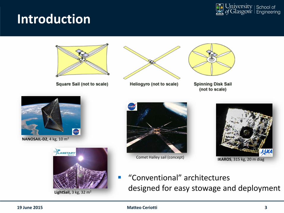
Introduction
19 June 2015 3Matteo Ceriotti
“Conventional” architecturesdesigned for easy stowage and deployment
NANOSAIL-D2, 4 kg, 10 m2
LightSail, 3 kg, 32 m2
Comet Halley sail (concept) IKAROS, 315 kg, 20 m diag
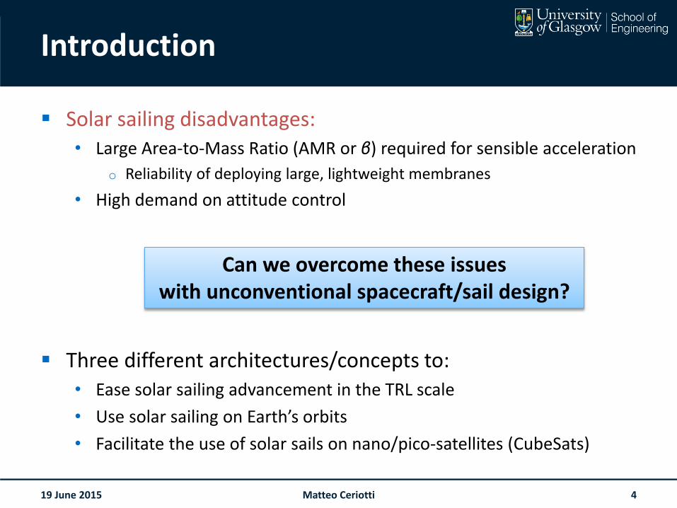
Introduction
Solar sailing disadvantages:• Large Area-to-Mass Ratio (AMR or β) required for sensible acceleration
o Reliability of deploying large, lightweight membranes
• High demand on attitude control
Three different architectures/concepts to:• Ease solar sailing advancement in the TRL scale
• Use solar sailing on Earth’s orbits
• Facilitate the use of solar sails on nano/pico-satellites (CubeSats)
19 June 2015 4Matteo Ceriotti
Can we overcome these issueswith unconventional spacecraft/sail design?
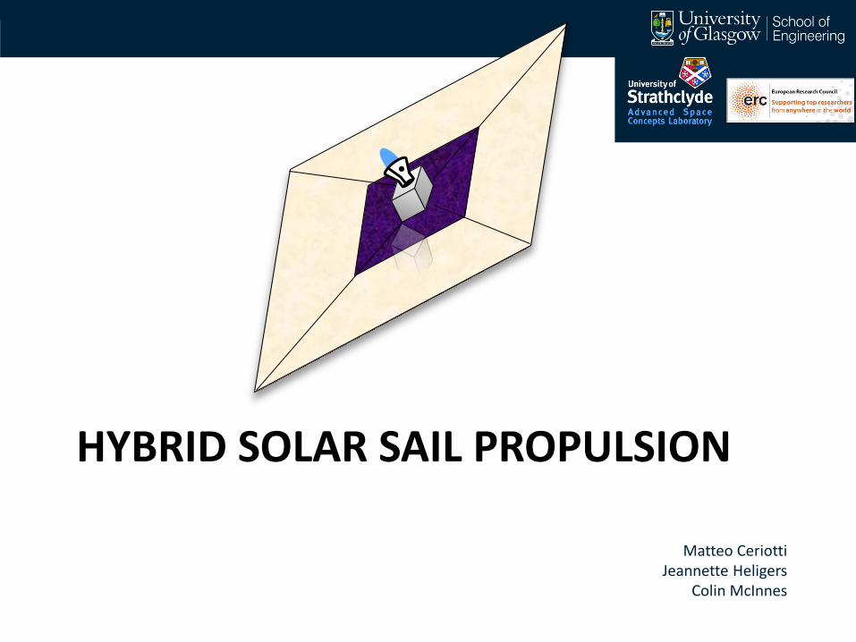
HYBRID SOLAR SAIL PROPULSION
Matteo CeriottiJeannette Heligers
Colin McInnes
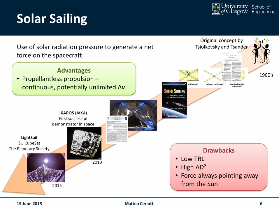
Solar Sailing
19 June 2015
Use of solar radiation pressure to generate a net force on the spacecraft
IKAROS (JAXA)First successful
demonstrator in space
2010
Drawbacks• Low TRL• High AD2
• Force always pointing away from the Sun
Advantages• Propellantless propulsion –
continuous, potentially unlimited Δv
1900’s
NASA
Original concept by Tsiolkovsky and Tsander
LightSail3U CubeSat
The Planetary Society
2015
Matteo Ceriotti 6
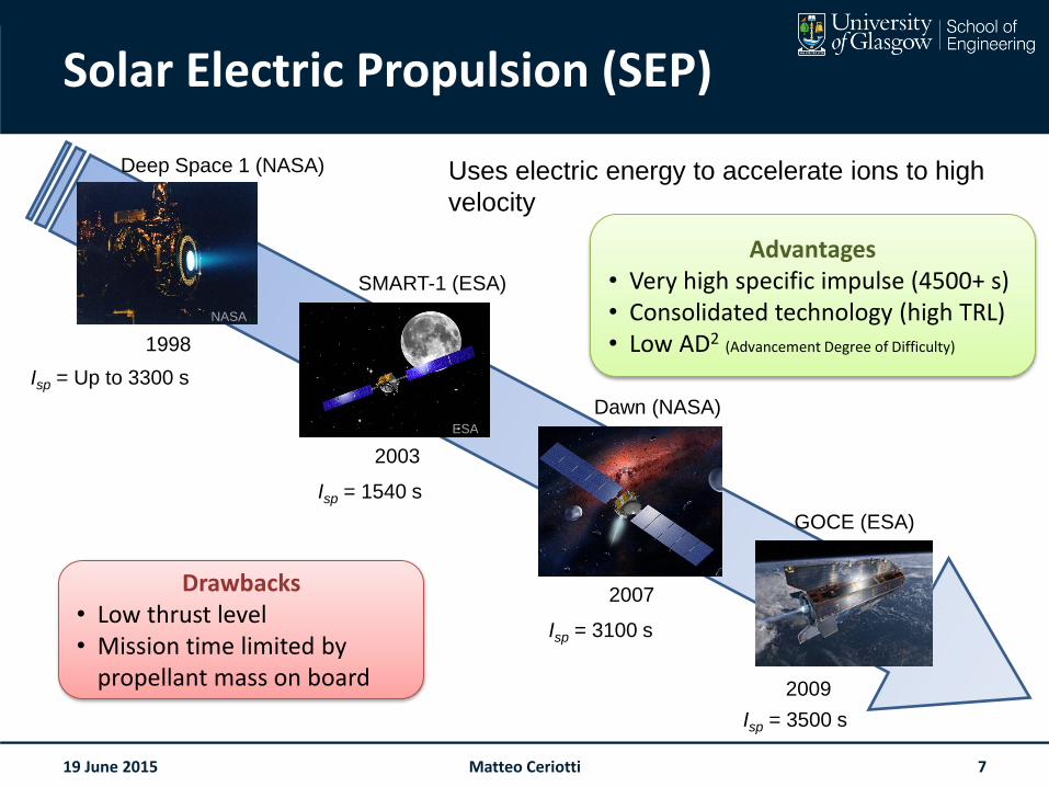
Solar Electric Propulsion (SEP)
19 June 2015
NASA
Deep Space 1 (NASA)
1998
ESA
SMART-1 (ESA)
2003
Dawn (NASA)
2007
GOCE (ESA)
2009
Isp = 3500 s
Isp = 3100 s
Isp = 1540 s
Advantages• Very high specific impulse (4500+ s)• Consolidated technology (high TRL)• Low AD2 (Advancement Degree of Difficulty)
Drawbacks• Low thrust level• Mission time limited by
propellant mass on board
Isp = Up to 3300 s
Uses electric energy to accelerate ions to high
velocity
Matteo Ceriotti 7
19 June 2015
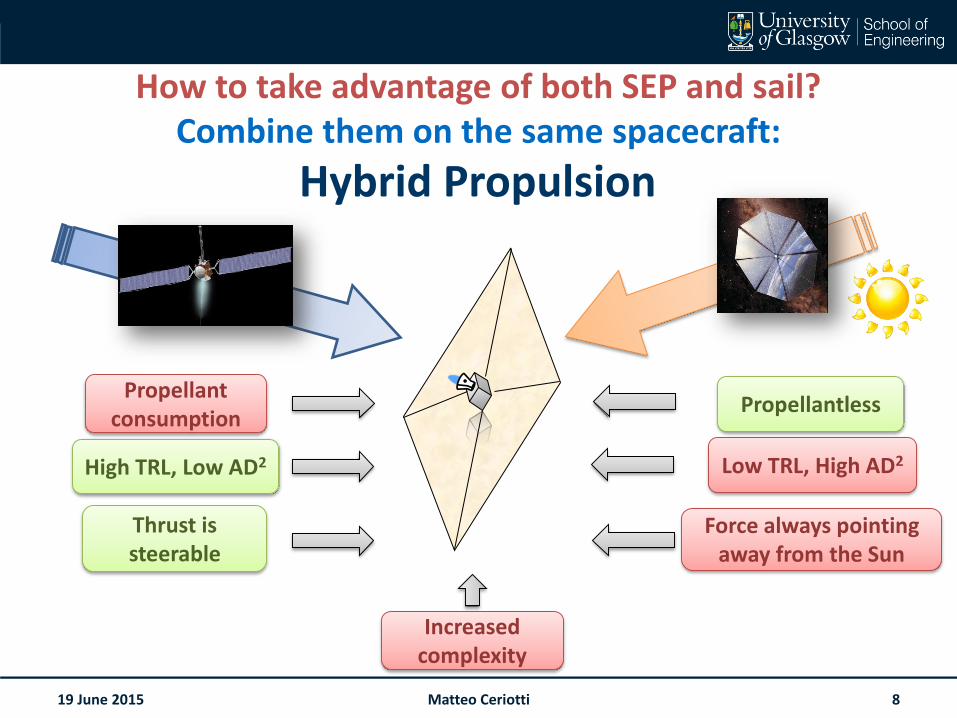
Hybrid Propulsion
Force always pointing away from the Sun
Propellant consumption
Low TRL, High AD2
Propellantless
Thrust is steerable
High TRL, Low AD2
Increased complexity
How to take advantage of both SEP and sail?Combine them on the same spacecraft:
Matteo Ceriotti 8
19 June 2015
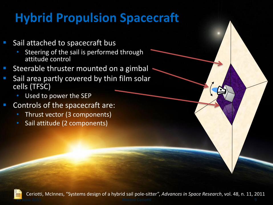
Hybrid Propulsion Spacecraft
Sail attached to spacecraft bus• Steering of the sail is performed through
attitude control
Steerable thruster mounted on a gimbal Sail area partly covered by thin film solar
cells (TFSC)• Used to power the SEP
Controls of the spacecraft are:• Thrust vector (3 components)• Sail attitude (2 components)
Ceriotti, McInnes, “Systems design of a hybrid sail pole-sitter”, Advances in Space Research, vol. 48, n. 11, 2011Matteo Ceriotti 9
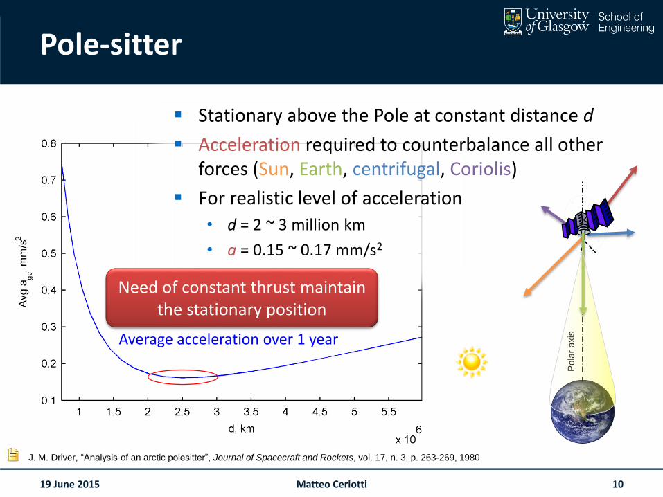
Pole-sitter
19 June 2015
J. M. Driver, “Analysis of an arctic polesitter”, Journal of Spacecraft and Rockets, vol. 17, n. 3, p. 263-269, 1980
Average acceleration over 1 year
Need of constant thrust maintain the stationary position
Stationary above the Pole at constant distance d
Acceleration required to counterbalance all other forces (Sun, Earth, centrifugal, Coriolis)
For realistic level of acceleration
• d = 2 ~ 3 million km
• a = 0.15 ~ 0.17 mm/s2
Matteo Ceriotti 10
Pola
r axis
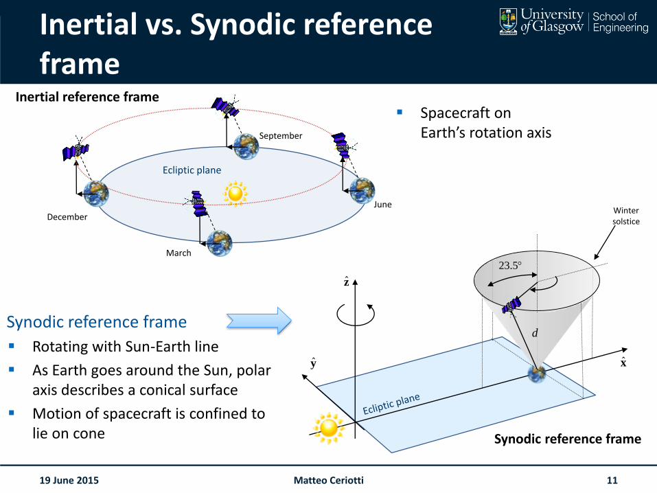
Inertial vs. Synodic reference frame
19 June 2015
Synodic reference frame
Rotating with Sun-Earth line
As Earth goes around the Sun, polar axis describes a conical surface
Motion of spacecraft is confined to lie on cone
y x
z
Winter solstice
d
23.5
Synodic reference frame
Inertial reference frame
June
September
December
March
Ecliptic plane
Spacecraft on Earth’s rotation axis
Matteo Ceriotti 11
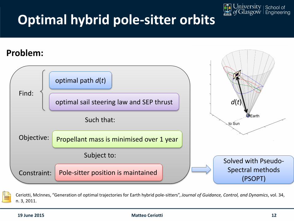
Optimal hybrid pole-sitter orbits
19 June 2015
Problem:
Ceriotti, McInnes, “Generation of optimal trajectories for Earth hybrid pole-sitters”, Journal of Guidance, Control, and Dynamics, vol. 34, n. 3, 2011.
Solved with Pseudo-Spectral methods
(PSOPT)
d(t)Find:
Such that:
Objective:
Subject to:
Constraint:
optimal path d(t)
optimal sail steering law and SEP thrust
Propellant mass is minimised over 1 year
Pole-sitter position is maintained
Matteo Ceriotti 12
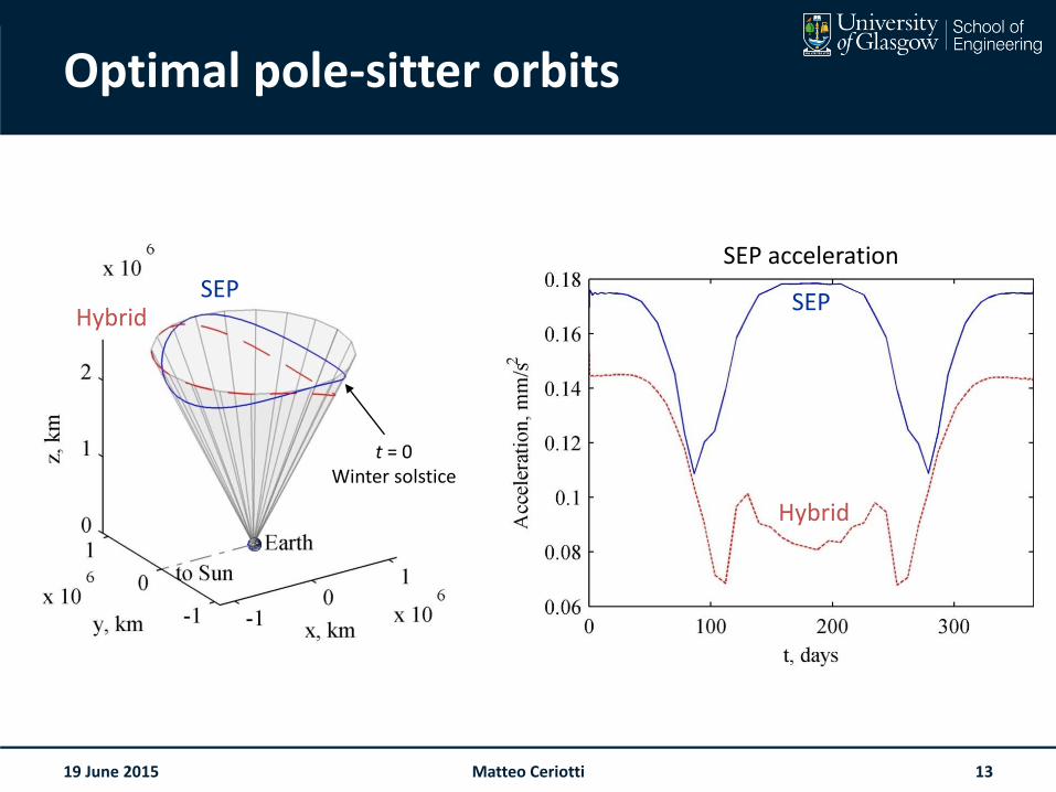
Optimal pole-sitter orbits
19 June 2015
HybridSEP
t = 0Winter solstice
SEP acceleration
Hybrid
SEP
Matteo Ceriotti 13
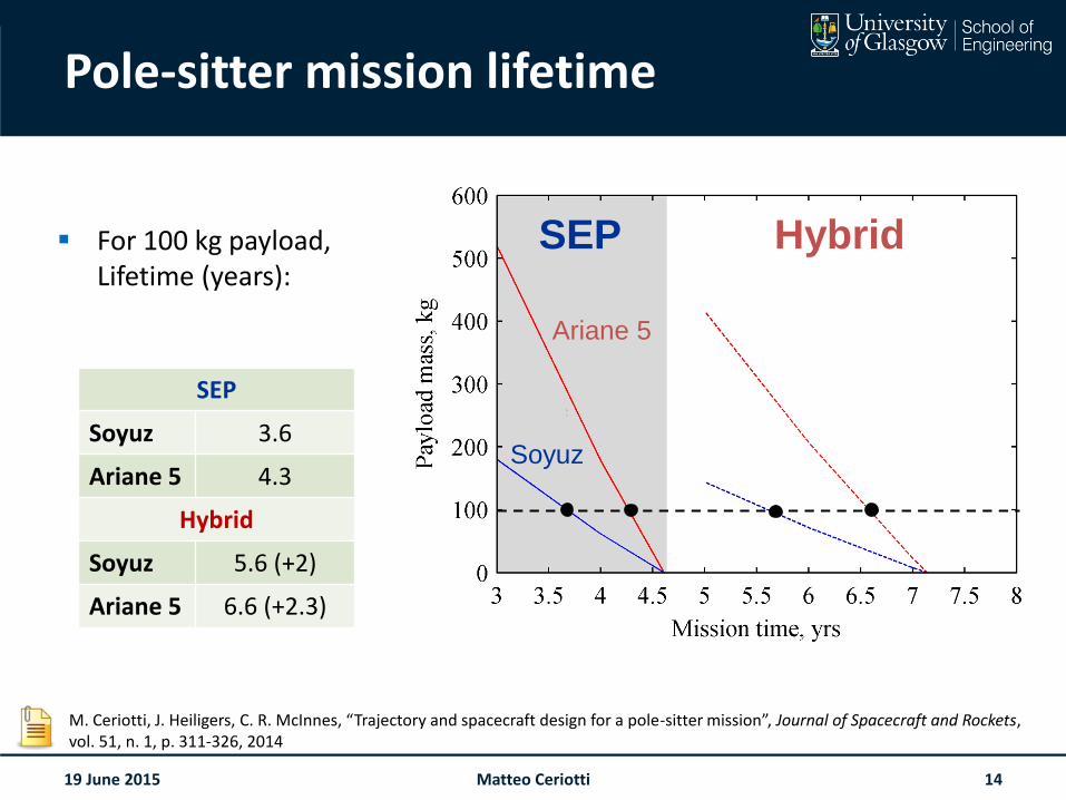
Pole-sitter mission lifetime
For 100 kg payload, Lifetime (years):
19 June 2015
HybridSEP
Ariane 5
Soyuz
SEP
Soyuz 3.6
Ariane 5 4.3
Hybrid
Soyuz 5.6 (+2)
Ariane 5 6.6 (+2.3)
M. Ceriotti, J. Heiligers, C. R. McInnes, “Trajectory and spacecraft design for a pole-sitter mission”, Journal of Spacecraft and Rockets, vol. 51, n. 1, p. 311-326, 2014
Matteo Ceriotti 14
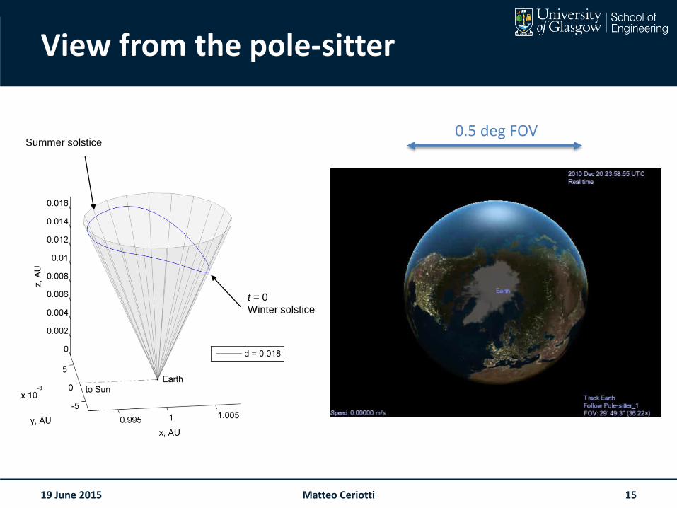
View from the pole-sitter
19 June 2015
t = 0
Winter solstice
Summer solstice0.5 deg FOV
Matteo Ceriotti 15
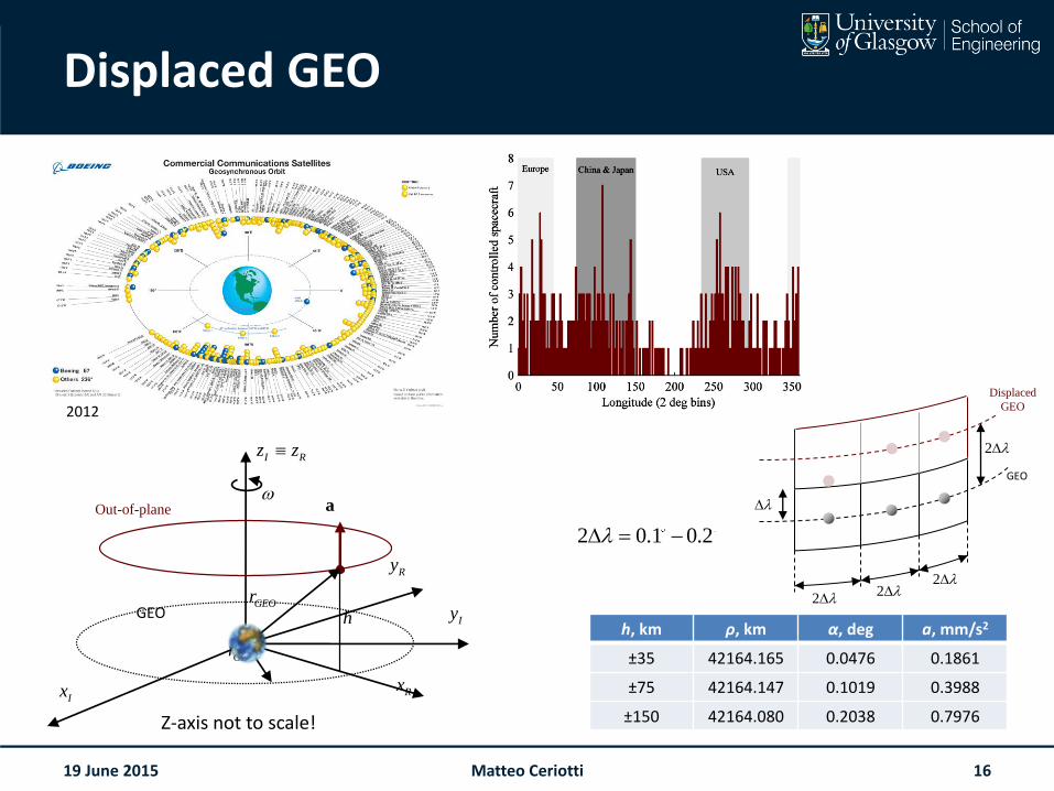
Displaced GEO
19 June 2015
2 0.1 0.2
h, km ρ, km α, deg a, mm/s2
±35 42164.165 0.0476 0.1861
±75 42164.147 0.1019 0.3988
±150 42164.080 0.2038 0.7976
2012
a Out-of-plane
Ix
Rx
GEO GEOr
GEOr
Ry
h Iy
I Rz z
Z-axis not to scale!
2 2 2
2
GEO
Displaced
GEO
Matteo Ceriotti 16
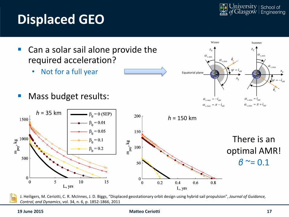
Displaced GEO
Can a solar sail alone provide the required acceleration?• Not for a full year
Mass budget results:
19 June 2015
h = 35 kmh = 150 km
Ex
Ez
obli
ˆsr
Ex
Ez
Summer
,mins ,mins
,maxs
,maxs
.min
,max
s obl
s obl
i
i
Winter
.min
,max
s obl
s obl
i
i
obli
ˆsr
Equatorial plane
J. Heiligers, M. Ceriotti, C. R. McInnes, J. D. Biggs, “Displaced geostationary orbit design using hybrid sail propulsion”, Journal of Guidance, Control, and Dynamics, vol. 34, n. 6, p. 1852-1866, 2011
There is an optimal AMR!
β ~= 0.1
Matteo Ceriotti 17
Earth solar sailing
How can we use solar radiation pressure only for orbit manoeuvring around the Earth?
19 June 2015 Matteo Ceriotti 18
ADDING AN ELECTRIC THRUSTER IS CHEATING!
It’s no more solar sailing!
Earth solar sailing
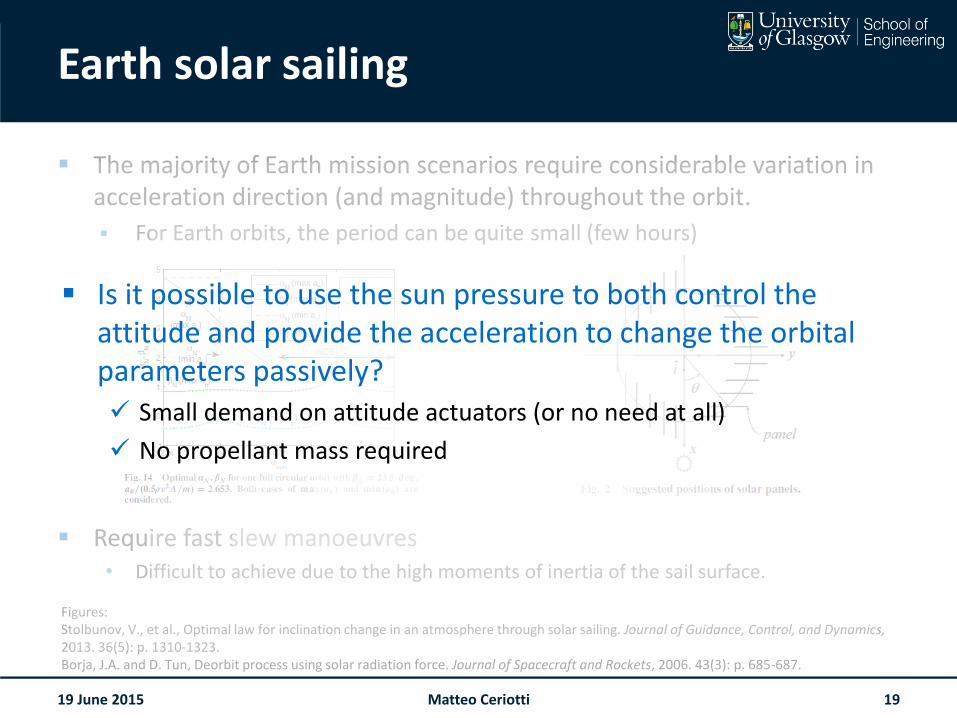
The majority of Earth mission scenarios require considerable variation in acceleration direction (and magnitude) throughout the orbit.
For Earth orbits, the period can be quite small (few hours)
Require fast slew manoeuvres• Difficult to achieve due to the high moments of inertia of the sail surface.
19 June 2015
Figures:Stolbunov, V., et al., Optimal law for inclination change in an atmosphere through solar sailing. Journal of Guidance, Control, and Dynamics, 2013. 36(5): p. 1310-1323.Borja, J.A. and D. Tun, Deorbit process using solar radiation force. Journal of Spacecraft and Rockets, 2006. 43(3): p. 685-687.
Matteo Ceriotti 19
Is it possible to use the sun pressure to both control the attitude and provide the acceleration to change the orbital parameters passively? Small demand on attitude actuators (or no need at all)
No propellant mass required
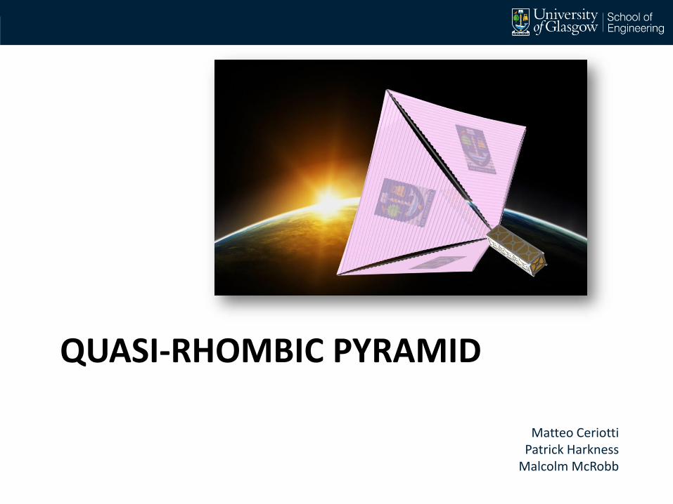
QUASI-RHOMBIC PYRAMID
Matteo CeriottiPatrick Harkness
Malcolm McRobb
Quasi-rhombic pyramid
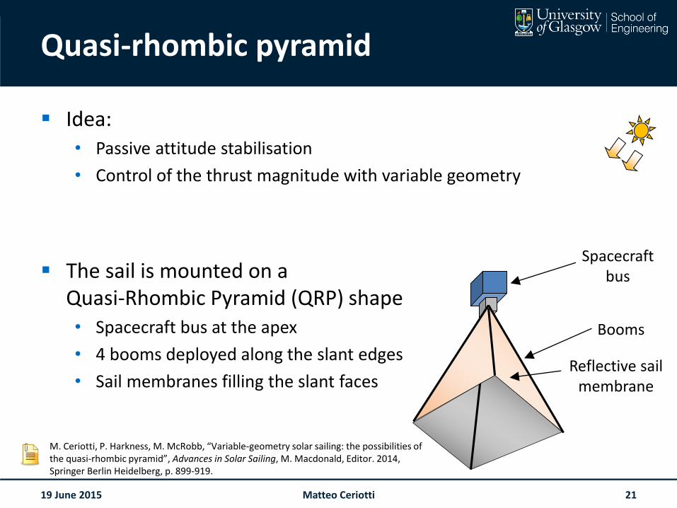
Idea:• Passive attitude stabilisation
• Control of the thrust magnitude with variable geometry
The sail is mounted on a Quasi-Rhombic Pyramid (QRP) shape• Spacecraft bus at the apex
• 4 booms deployed along the slant edges
• Sail membranes filling the slant faces
19 June 2015
Reflective sail membrane
Spacecraft bus
Booms
M. Ceriotti, P. Harkness, M. McRobb, “Variable-geometry solar sailing: the possibilities of the quasi-rhombic pyramid”, Advances in Solar Sailing, M. Macdonald, Editor. 2014, Springer Berlin Heidelberg, p. 899-919.
Matteo Ceriotti 21
Quasi-rhombic pyramid
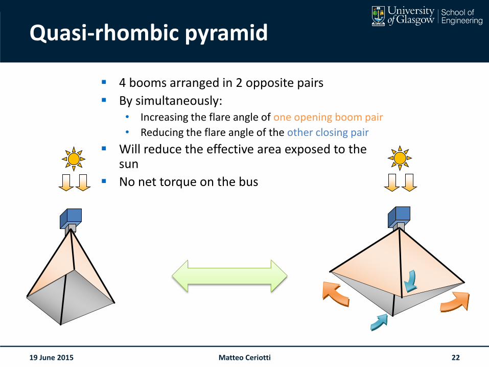
4 booms arranged in 2 opposite pairs
By simultaneously:• Increasing the flare angle of one opening boom pair
• Reducing the flare angle of the other closing pair
Will reduce the effective area exposed to the sun
No net torque on the bus
19 June 2015 Matteo Ceriotti 22
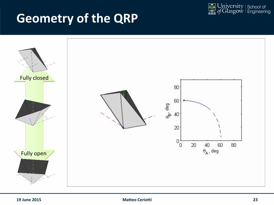
Geometry of the QRP
19 June 2015
Fully closed
Fully open
Matteo Ceriotti 23
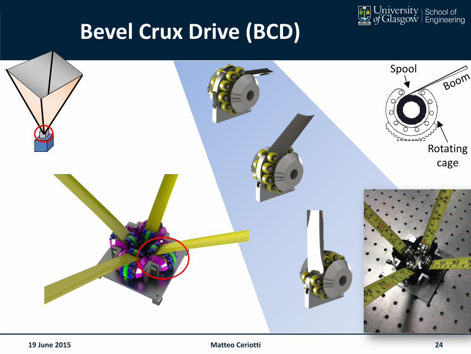
Bevel Crux Drive (BCD)
19 June 2015
Spool
Rotatingcage
Matteo Ceriotti 24
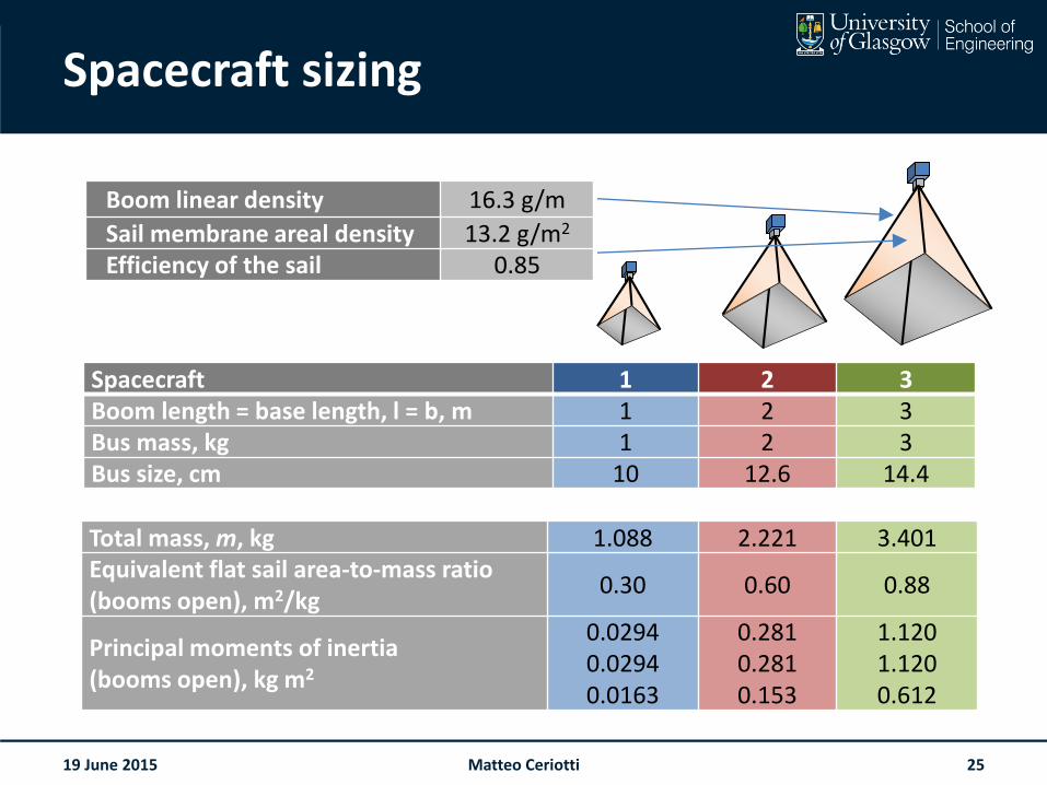
Spacecraft sizing
19 June 2015
Spacecraft 1 2 3Boom length = base length, l = b, m 1 2 3Bus mass, kg 1 2 3Bus size, cm 10 12.6 14.4
Total mass, m, kg 1.088 2.221 3.401Equivalent flat sail area-to-mass ratio(booms open), m2/kg
0.30 0.60 0.88
Principal moments of inertia(booms open), kg m2
0.02940.02940.0163
0.2810.2810.153
1.1201.1200.612
Boom linear density 16.3 g/m
Sail membrane areal density 13.2 g/m2
Efficiency of the sail 0.85
Matteo Ceriotti 25
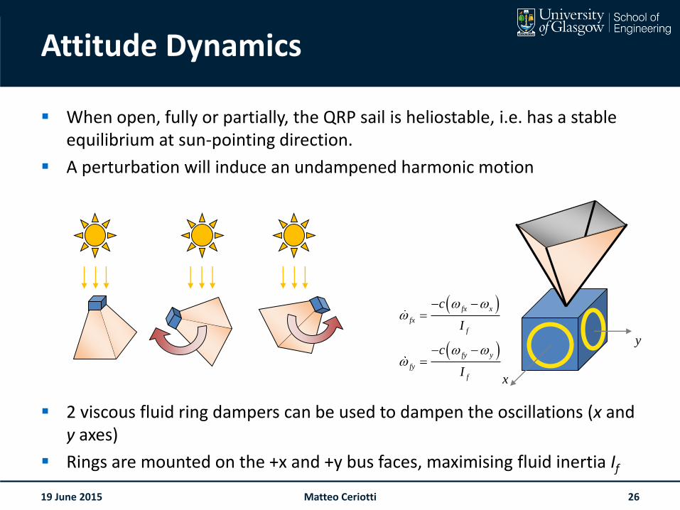
Attitude Dynamics
When open, fully or partially, the QRP sail is heliostable, i.e. has a stable equilibrium at sun-pointing direction.
A perturbation will induce an undampened harmonic motion
2 viscous fluid ring dampers can be used to dampen the oscillations (x and y axes)
Rings are mounted on the +x and +y bus faces, maximising fluid inertia If
19 June 2015
y
x
fx x
fx
f
fy y
fy
f
c
I
c
I
Matteo Ceriotti 26
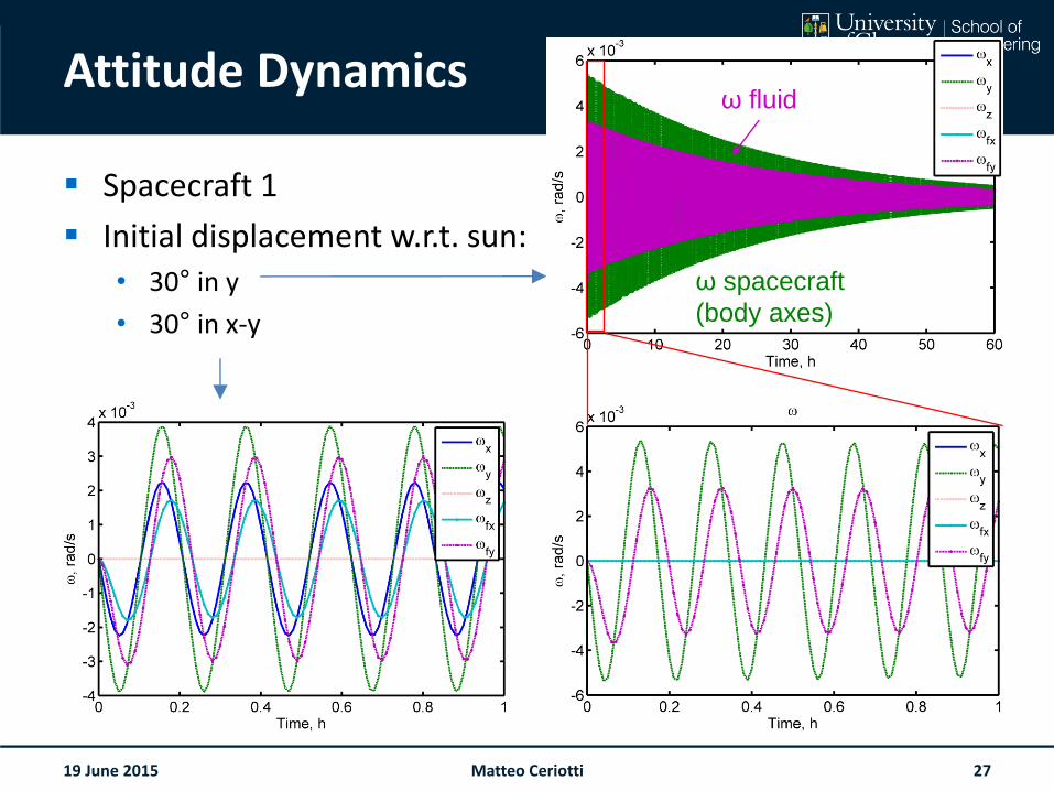
Attitude Dynamics
Spacecraft 1
Initial displacement w.r.t. sun:• 30° in y
• 30° in x-y
19 June 2015
ω spacecraft
(body axes)
ω fluid
Matteo Ceriotti 27
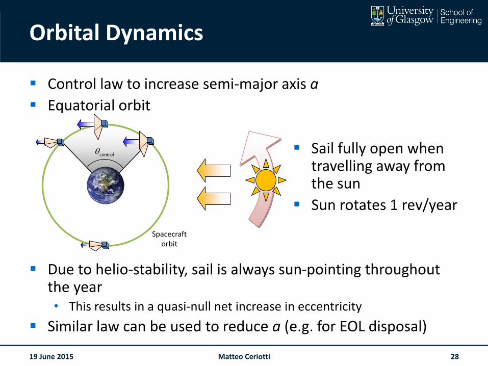
Orbital Dynamics
Control law to increase semi-major axis a
Equatorial orbit
Sail fully open when travelling away from the sun
Sun rotates 1 rev/year
Due to helio-stability, sail is always sun-pointing throughout the year• This results in a quasi-null net increase in eccentricity
Similar law can be used to reduce a (e.g. for EOL disposal)
19 June 2015
Spacecraftorbit
control
Matteo Ceriotti 28
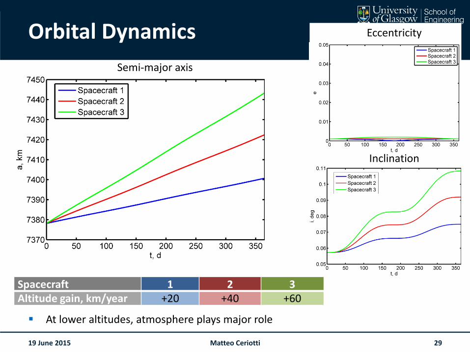
Orbital Dynamics
At lower altitudes, atmosphere plays major role
19 June 2015
Spacecraft 1 2 3Altitude gain, km/year +20 +40 +60
Semi-major axis
Eccentricity
Inclination
Matteo Ceriotti 29
WHAT HAPPENS DURING ECLIPSES?
Matteo CeriottiPatrick HarknessLeonard Felicetti
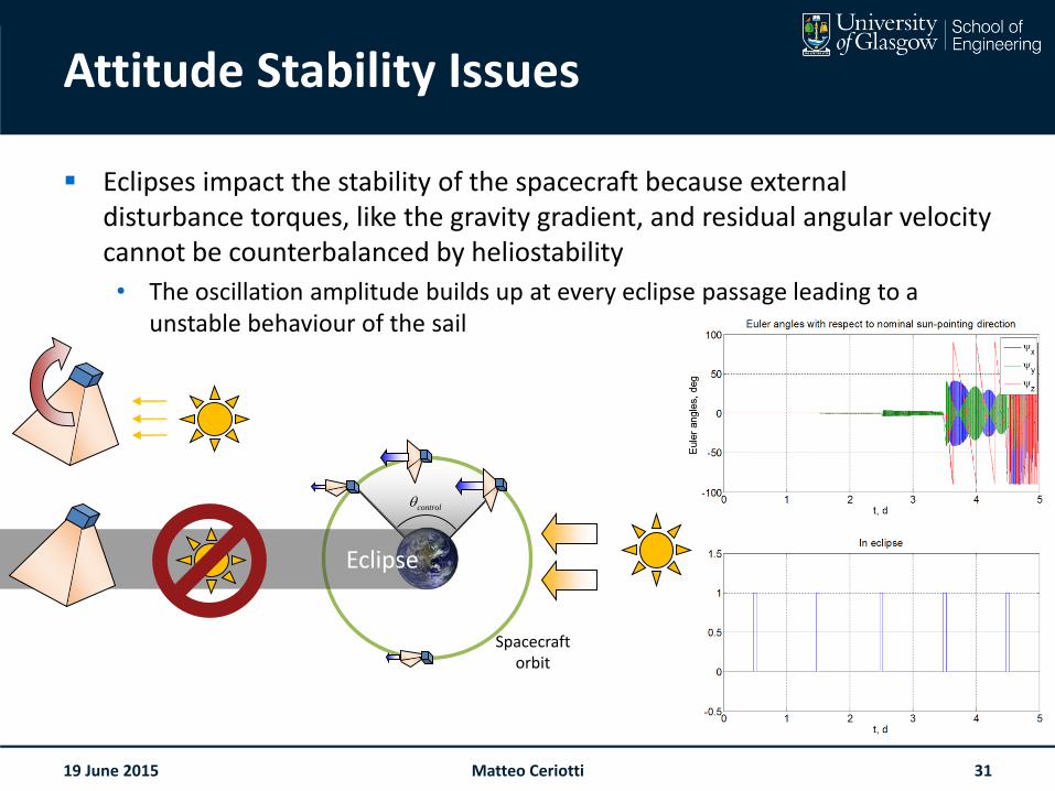
Attitude Stability Issues
Eclipses impact the stability of the spacecraft because external disturbance torques, like the gravity gradient, and residual angular velocity cannot be counterbalanced by heliostability
• The oscillation amplitude builds up at every eclipse passage leading to a unstable behaviour of the sail
19 June 2015
Spacecraftorbit
control
Eclipse
Matteo Ceriotti 31
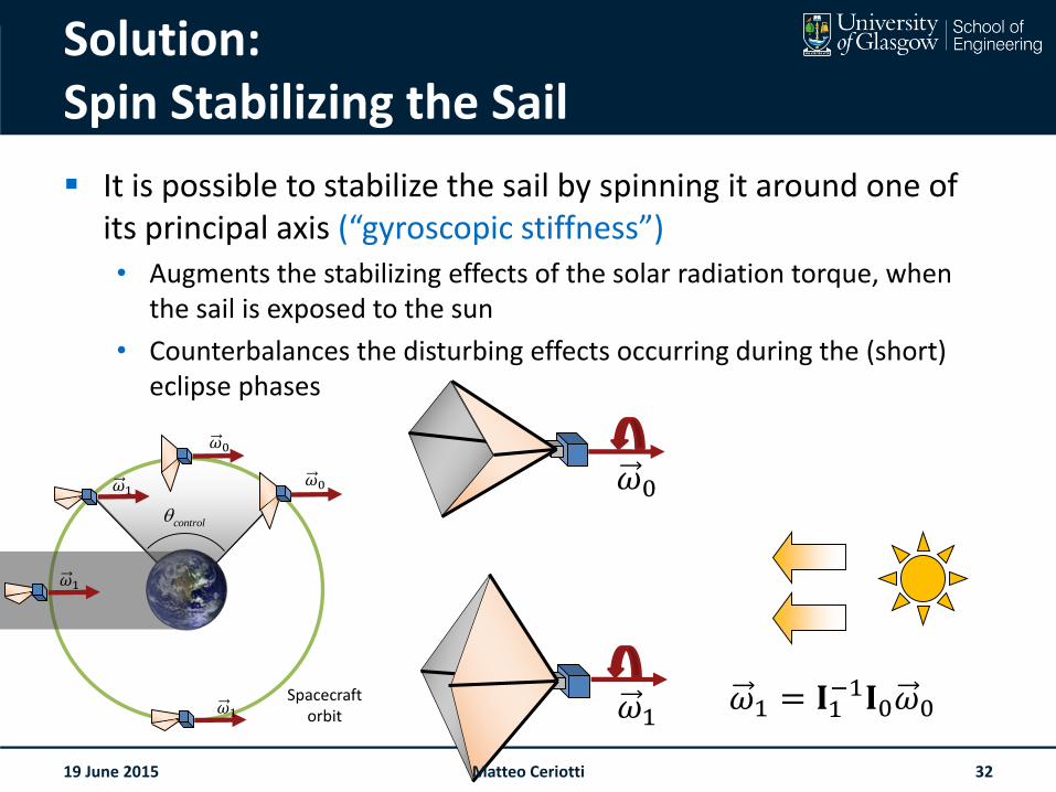
Solution:Spin Stabilizing the Sail
It is possible to stabilize the sail by spinning it around one of its principal axis (“gyroscopic stiffness”)• Augments the stabilizing effects of the solar radiation torque, when
the sail is exposed to the sun
• Counterbalances the disturbing effects occurring during the (short) eclipse phases
19 June 2015
Spacecraftorbit
control
𝜔0
𝜔0
𝜔1
𝜔1
𝜔1𝜔1 = 𝐈1
−1𝐈0𝜔0
𝜔0
𝜔1
Matteo Ceriotti 32
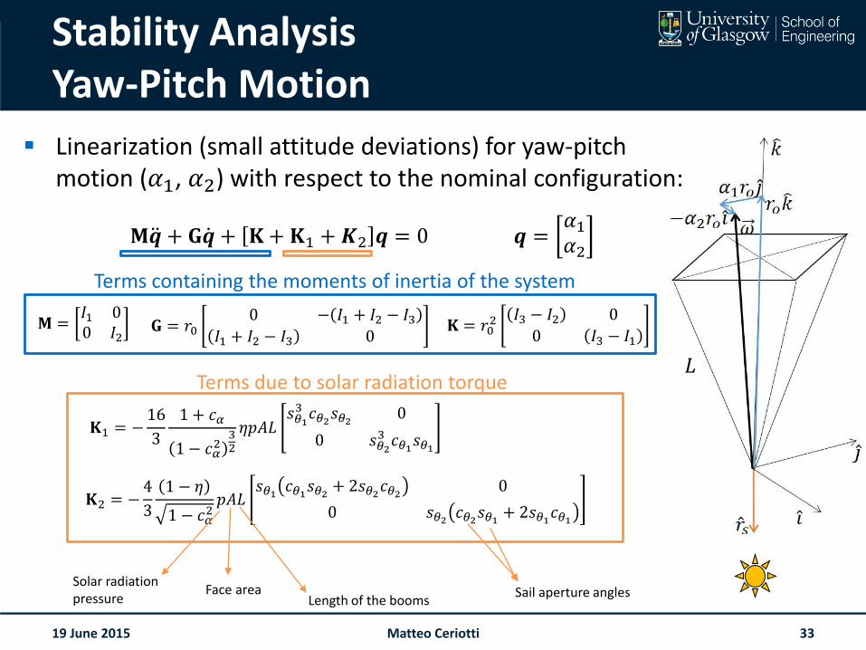
Stability AnalysisYaw-Pitch Motion
19 June 2015
𝐌 𝒒 + 𝐆 𝒒 + 𝐊 + 𝐊1 +𝑲2 𝒒 = 0 𝒒 =𝛼1𝛼2
𝐌 =𝐼1 00 𝐼2
𝐆 = 𝑟00 − 𝐼1 + 𝐼2 − 𝐼3
𝐼1 + 𝐼2 − 𝐼3 0𝐊 = 𝑟0
2 𝐼3 − 𝐼2 0
0 𝐼3 − 𝐼1
𝐊2 = −4
3
1 − 𝜂
1 − 𝑐𝛼2𝑝𝐴𝐿
𝑠𝜃1 𝑐𝜃1𝑠𝜃2 + 2𝑠𝜃2𝑐𝜃2 0
0 𝑠𝜃2 𝑐𝜃2𝑠𝜃1 + 2𝑠𝜃1𝑐𝜃1
𝐊1 = −16
3
1 + 𝑐𝛼
1 − 𝑐𝛼2
32
𝜂𝑝𝐴𝐿𝑠𝜃13 𝑐𝜃2𝑠𝜃2 0
0 𝑠𝜃23 𝑐𝜃1𝑠𝜃1
Terms due to solar radiation torque
Solar radiation pressure
Face area Sail aperture anglesLength of the booms
𝐿
Linearization (small attitude deviations) for yaw-pitch motion (𝛼1, 𝛼2) with respect to the nominal configuration:
Matteo Ceriotti 33
Terms containing the moments of inertia of the system
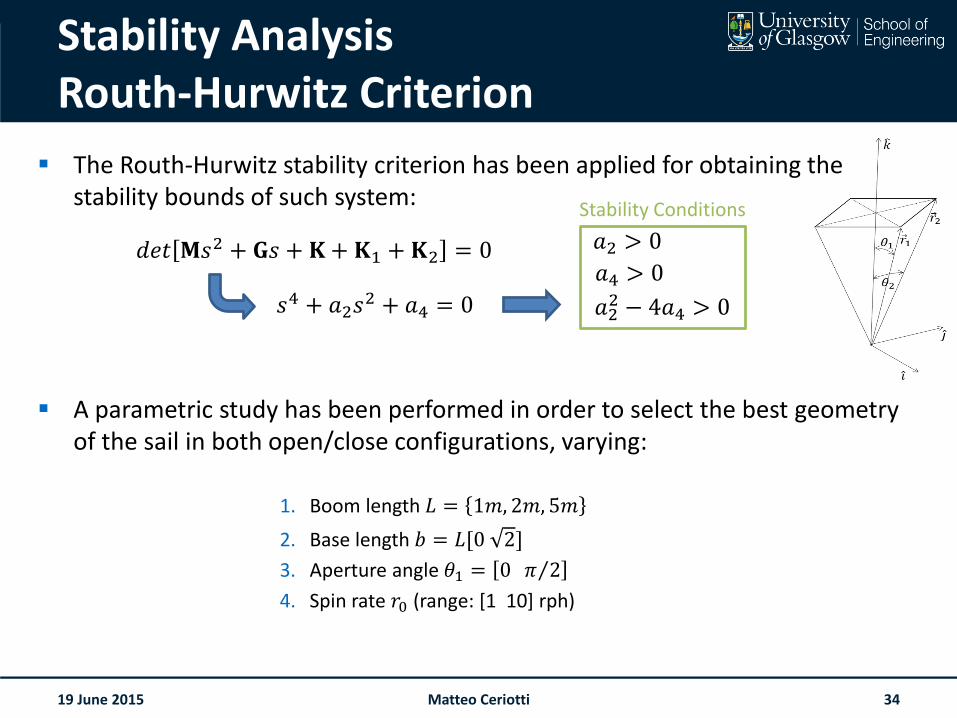
The Routh-Hurwitz stability criterion has been applied for obtaining the stability bounds of such system:
A parametric study has been performed in order to select the best geometry of the sail in both open/close configurations, varying:
1. Boom length 𝐿 = 1𝑚, 2𝑚, 5𝑚
2. Base length 𝑏 = 𝐿[0 2]
3. Aperture angle 𝜃1 = 0 𝜋 2
4. Spin rate 𝑟0 (range: [1 10] rph)
Stability AnalysisRouth-Hurwitz Criterion
19 June 2015
𝑑𝑒𝑡 𝐌𝑠2 + 𝐆𝑠 + 𝐊 + 𝐊1 + 𝐊2 = 0
𝑠4 + 𝑎2𝑠2 + 𝑎4 = 0
𝑎2 > 0
𝑎4 > 0
𝑎22 − 4𝑎4 > 0
Stability Conditions
Matteo Ceriotti 34
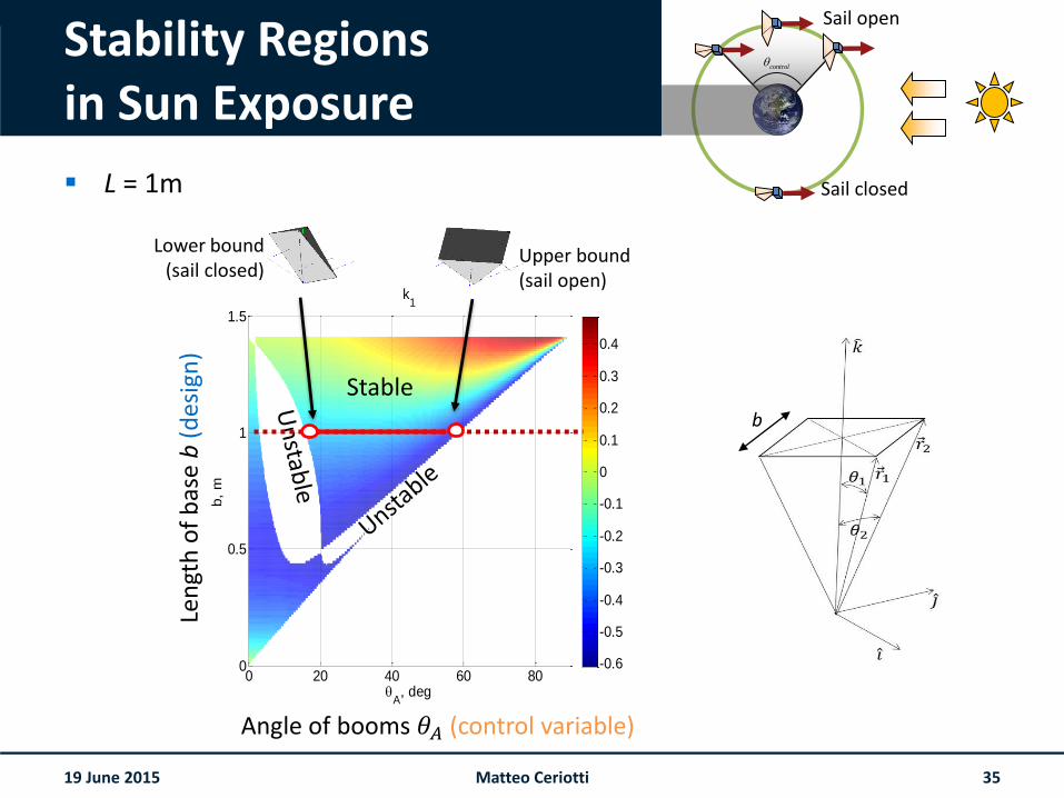
Stability Regionsin Sun Exposure
L = 1m
19 June 2015
control
Sail open
Sail closed
0 20 40 60 800
0.5
1
1.5
k1
A, deg
b,
m
0 20 40 60 800
0.5
1
1.5
A, deg
k2
b,
m
-0.6
-0.5
-0.4
-0.3
-0.2
-0.1
0
0.1
0.2
0.3
0.4
-0.6
-0.5
-0.4
-0.3
-0.2
-0.1
0
0.1
0.2
0.3
0.4
Stable
Lower bound(sail closed)
Upper bound (sail open)
Len
gth
of
bas
e b
(des
ign
)
Angle of booms 𝜃𝐴 (control variable)
Matteo Ceriotti 35
b
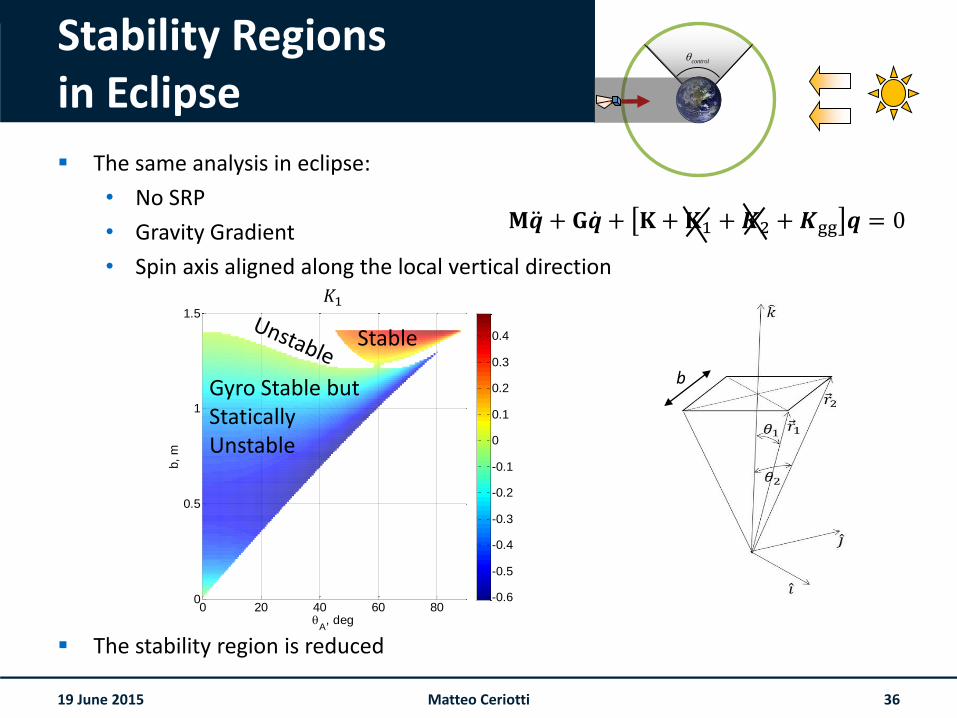
Stability Regionsin Eclipse
The same analysis in eclipse:
• No SRP
• Gravity Gradient
• Spin axis aligned along the local vertical direction
The stability region is reduced
19 June 2015
𝐌 𝒒 + 𝐆 𝒒 + 𝐊 + 𝐊1 +𝑲2 +𝑲gg 𝒒 = 0
control
0 20 40 60 800
0.5
1
1.5
A, deg
b,
m
0 20 40 60 800
0.5
1
1.5
A, deg
b,
m
-0.6
-0.5
-0.4
-0.3
-0.2
-0.1
0
0.1
0.2
0.3
0.4
-0.6
-0.5
-0.4
-0.3
-0.2
-0.1
0
0.1
0.2
0.3
0.4Stable
Gyro Stable but StaticallyUnstable
𝐾1
Matteo Ceriotti 36
b
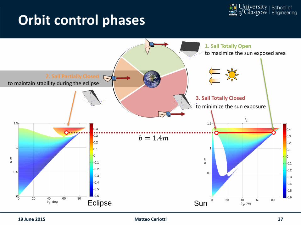
Orbit control phases
3. Sail Totally Closed
to minimize the sun exposure
19 June 2015
0 20 40 60 800
0.5
1
1.5
A, deg
b,
m
0 20 40 60 800
0.5
1
1.5
A, deg
b,
m
-0.6
-0.5
-0.4
-0.3
-0.2
-0.1
0
0.1
0.2
0.3
0.4
-0.6
-0.5
-0.4
-0.3
-0.2
-0.1
0
0.1
0.2
0.3
0.4
Eclipse0 20 40 60 80
0
0.5
1
1.5
k1
A, deg
b,
m
0 20 40 60 800
0.5
1
1.5
A, deg
k2
b,
m
-0.6
-0.5
-0.4
-0.3
-0.2
-0.1
0
0.1
0.2
0.3
0.4
-0.6
-0.5
-0.4
-0.3
-0.2
-0.1
0
0.1
0.2
0.3
0.4
Sun
2. Sail Partially Closedto maintain stability during the eclipse
1. Sail Totally Opento maximize the sun exposed area
𝑏 = 1.4𝑚
Matteo Ceriotti 37
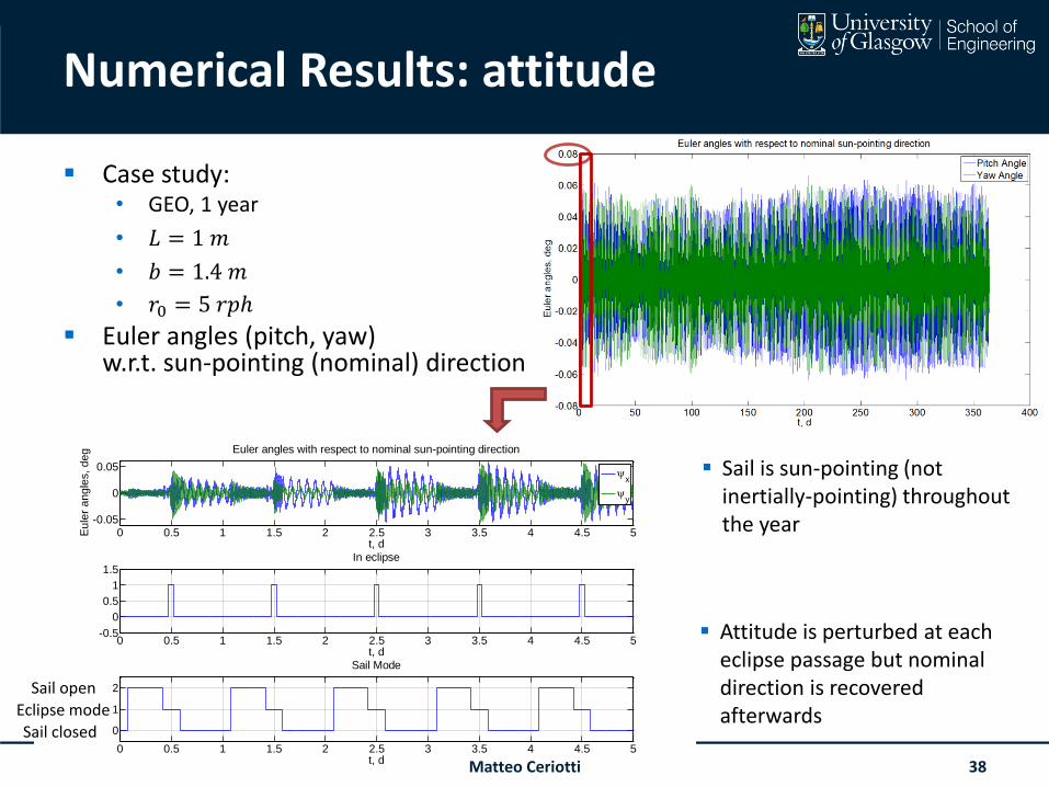
Numerical Results: attitude
Case study:• GEO, 1 year
• 𝐿 = 1 𝑚
• 𝑏 = 1.4 𝑚
• 𝑟0 = 5 𝑟𝑝ℎ
Euler angles (pitch, yaw)w.r.t. sun-pointing (nominal) direction
19 June 2015
0 0.5 1 1.5 2 2.5 3 3.5 4 4.5 5-0.05
0
0.05
t, d
Eu
ler
an
gle
s,
de
g Euler angles with respect to nominal sun-pointing direction
x
y
0 0.5 1 1.5 2 2.5 3 3.5 4 4.5 5-0.5
0
0.5
1
1.5
t, d
In eclipse
0 0.5 1 1.5 2 2.5 3 3.5 4 4.5 5
0
1
2
t, d
Sail Mode
Sail closed
Eclipse mode
Sail open
Attitude is perturbed at each eclipse passage but nominal direction is recovered afterwards
Matteo Ceriotti 38
Sail is sun-pointing (not inertially-pointing) throughout the year
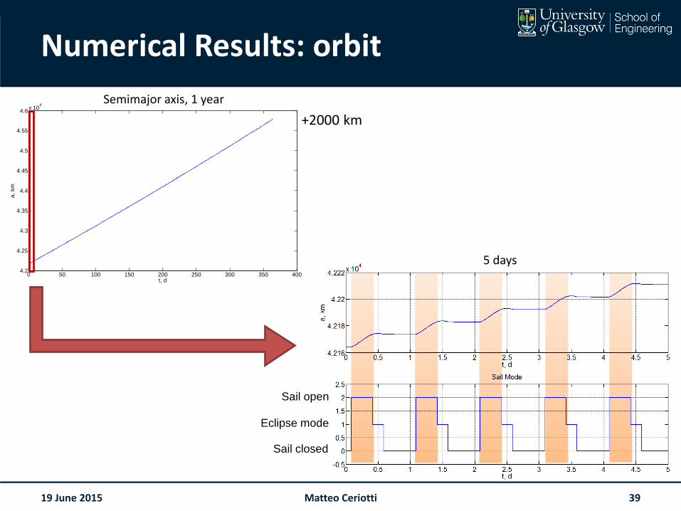
Numerical Results: orbit
19 June 2015
0 50 100 150 200 250 300 350 4004.2
4.25
4.3
4.35
4.4
4.45
4.5
4.55
4.6x 10
4
t, d
a,
km
Semi-major axis
Sail open
Eclipse mode
Sail closed
+2000 km
Semimajor axis, 1 year
5 days
Matteo Ceriotti 39
Earth solar sailing
QRP provides a passive, self-stabilizing effect under solar radiation pressure
By varying the boom angles, it is possible to change the effective area-to-mass ratio of the spacecraft for orbit control.
By spinning the sail, it is possible to achieve stable sun-pointing throughout the year and even in eclipses
Realistic architectures appear likely to have the capability to raise or lower the orbit of CubeSat-class spacecraft by several 10’s km/year in LEO (>1000 km), 1000’s km/year in GEO
19 June 2015 Matteo Ceriotti 40
Earth solar sailing
The heliostable sail (QRP) reduces the demands on an attitude control system
Yet, it requires control of the boom flare angle (open/close)
Is it possible to envisage a completely passive system?• Heliostability
+
• Orbit control
Use of a heliostable oscillating sailto create forces alternating throughout the orbit
19 June 2015 Matteo Ceriotti 41
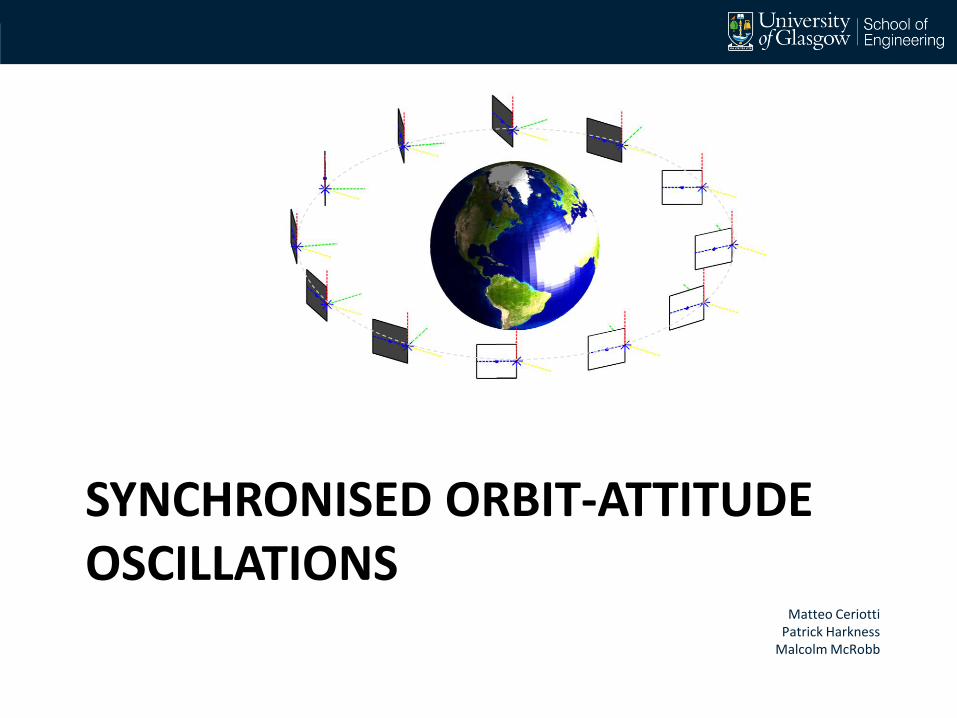
SYNCHRONISED ORBIT-ATTITUDE OSCILLATIONS
Matteo CeriottiPatrick Harkness
Malcolm McRobb
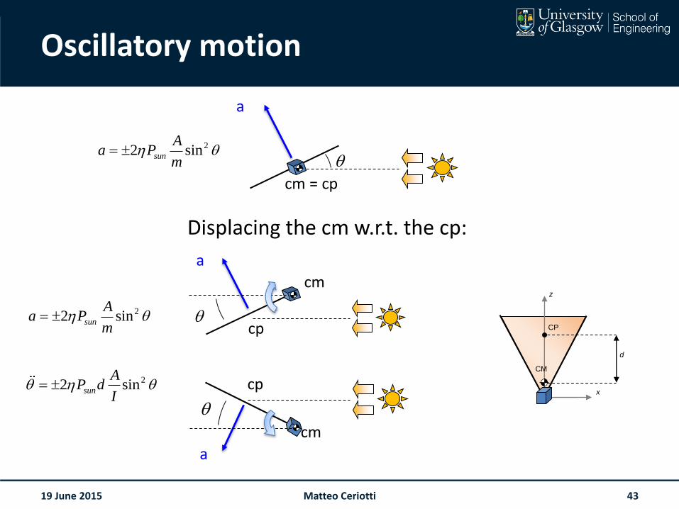
Oscillatory motion
Displacing the cm w.r.t. the cp:
19 June 2015
22 sinsun
Aa P
m
x
z
CP
CM
d
cm = cp
a
22 sinsun
Aa P
m
22 sinsun
AP d
I
cp
a
cm
cp
a
cm
Matteo Ceriotti 43
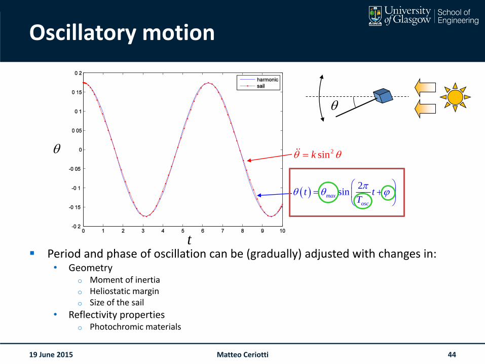
Oscillatory motion
Period and phase of oscillation can be (gradually) adjusted with changes in:• Geometry
o Moment of inertiao Heliostatic margino Size of the sail
• Reflectivity propertieso Photochromic materials
19 June 2015
2
sinmax
osc
t tT
2sink
t
Matteo Ceriotti 44
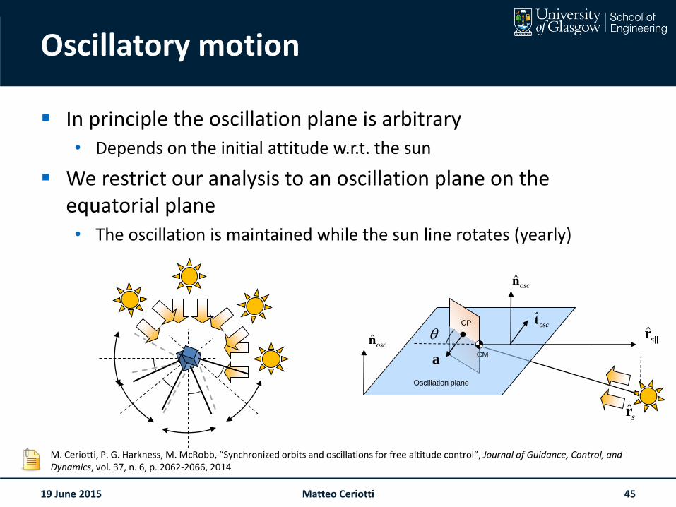
Oscillatory motion
In principle the oscillation plane is arbitrary• Depends on the initial attitude w.r.t. the sun
We restrict our analysis to an oscillation plane on the equatorial plane• The oscillation is maintained while the sun line rotates (yearly)
19 June 2015
ˆsr
ˆsr
ˆoscn
ˆoscn
CP
Oscillation plane
CMa
ˆosct
M. Ceriotti, P. G. Harkness, M. McRobb, “Synchronized orbits and oscillations for free altitude control”, Journal of Guidance, Control, and Dynamics, vol. 37, n. 6, p. 2062-2066, 2014
Matteo Ceriotti 45
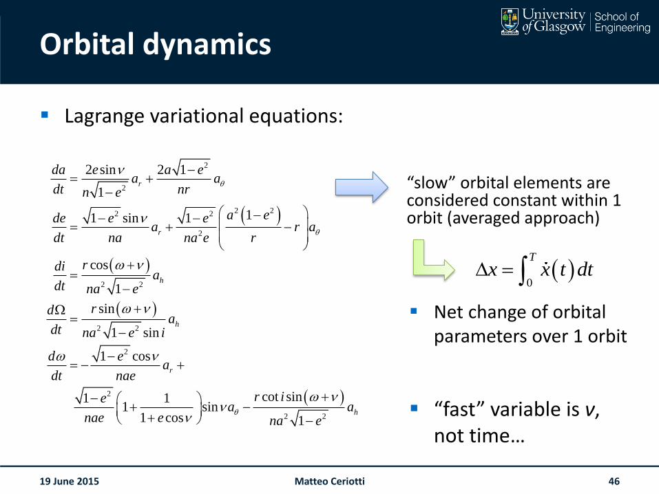
Orbital dynamics
Lagrange variational equations:
19 June 2015
2
2
2 22 2
2
2 2
2 2
2
2
2 2
2 sin 2 1
1
11 sin 1
cos
1
sin
1 sin
1 cos
cot sin1 11 sin
1 cos 1
r
r
h
h
r
h
da e a ea a
dt nrn e
a ede e ea r a
dt na rna e
rdia
dt na e
rda
dt na e i
d ea
dt nae
r iea a
nae e na e
0
T
x x t dt
Net change of orbital parameters over 1 orbit
“slow” orbital elements are considered constant within 1 orbit (averaged approach)
“fast” variable is ν, not time…
Matteo Ceriotti 46
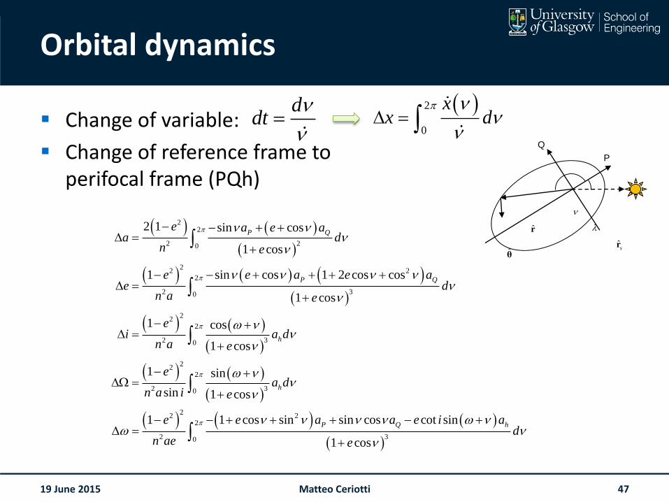
Orbital dynamics
Change of variable:
Change of reference frame toperifocal frame (PQh)
19 June 2015
22
2 20
22 2
2
2 30
22
2
2 30
22
2
2 30
22 2
2
2 1 sin cos
1 cos
1 sin cos 1 2 cos cos
1 cos
1 cos
1 cos
1 sin
sin 1 cos
1 1 cos sin sin co
P Q
P Q
h
h
P
e a e aa d
n e
e e a e ae d
n a e
ei a d
n a e
ea d
n a i e
e e a
n ae
2
30
s cot sin
1 cos
Q ha e i ad
e
2
0
xx d
r
θ
ˆsr
Q
P
ddt
Matteo Ceriotti 47
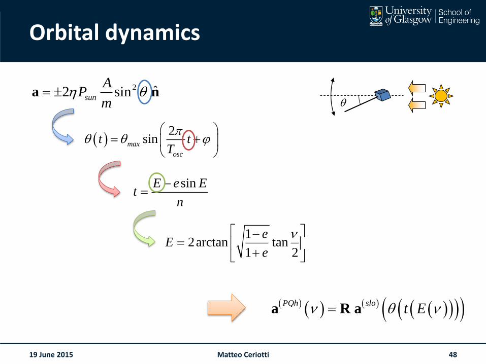
Orbital dynamics
19 June 2015
PQh slot E a R a
sinE e Et
n
2
sinmax
osc
t tT
2 ˆ2 sinsun
AP
m a n
12arctan tan
1 2
eE
e
Matteo Ceriotti 48
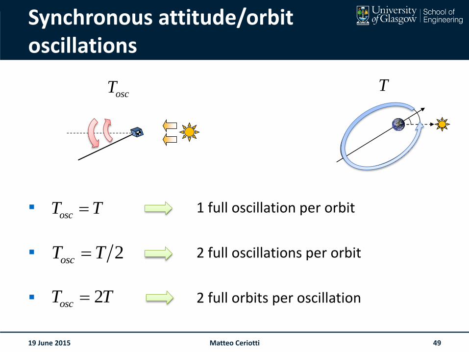
Synchronous attitude/orbit oscillations
1 full oscillation per orbit
2 full oscillations per orbit
2 full orbits per oscillation
19 June 2015
oscT T
2oscT T
2oscT T
oscT T
Matteo Ceriotti 49
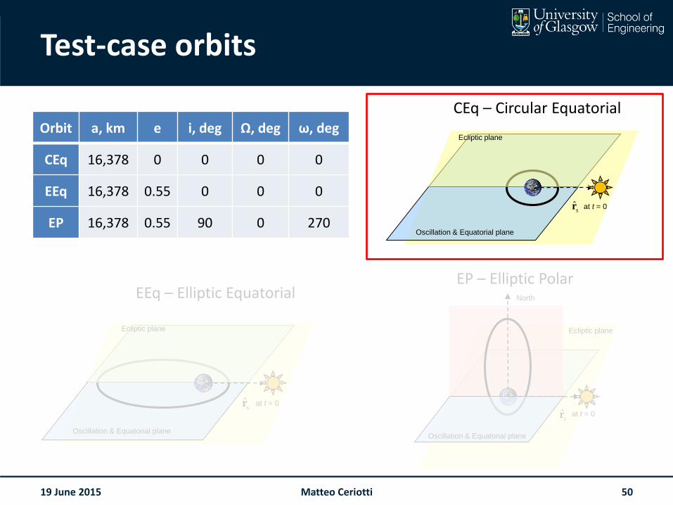
Test-case orbits
Orbit a, km e i, deg Ω, deg ω, deg
CEq 16,378 0 0 0 0
EEq 16,378 0.55 0 0 0
EP 16,378 0.55 90 0 270
19 June 2015
ˆsr at t = 0
Oscillation & Equatorial plane
Ecliptic plane
ˆsr at t = 0
Oscillation & Equatorial plane
Ecliptic plane
ˆsr at t = 0
North
Ecliptic plane
Oscillation & Equatorial plane
CEq – Circular Equatorial
EEq – Elliptic EquatorialEP – Elliptic Polar
Matteo Ceriotti 50
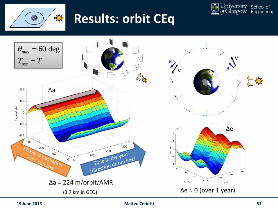
Results: orbit CEq
19 June 2015
60 degmax
oscT T
(3.7 km in GEO)
Δa = 224 m/orbit/AMRΔe ≈ 0 (over 1 year)
Δe
Δa
a
va
v
Matteo Ceriotti 51
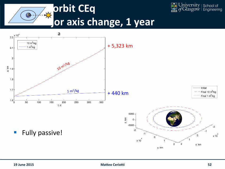
Results: orbit CEqSemimajor axis change, 1 year
Fully passive!
19 June 2015 52Matteo Ceriotti
+ 5,323 km
+ 440 km
a
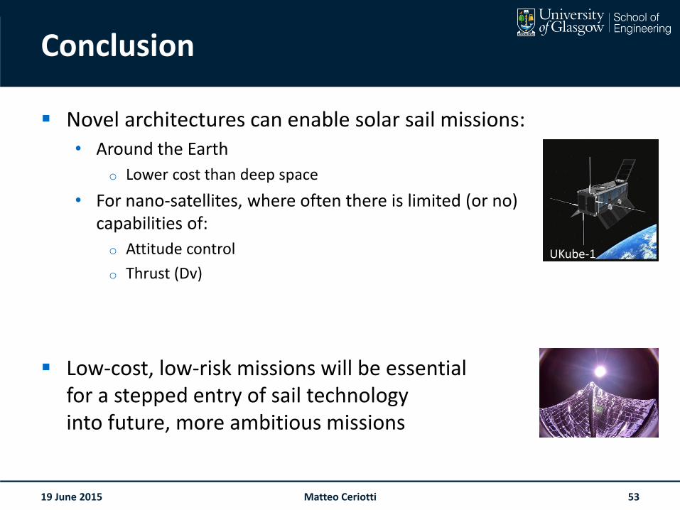
Conclusion
Novel architectures can enable solar sail missions:• Around the Earth
o Lower cost than deep space
• For nano-satellites, where often there is limited (or no) capabilities of:
o Attitude control
o Thrust (Dv)
Low-cost, low-risk missions will be essentialfor a stepped entry of sail technologyinto future, more ambitious missions
19 June 2015 Matteo Ceriotti 53
UKube-1
Space Glasgow
@SpaceGlasgow
www.glasgow.ac.uk/space
Thank you!
@mtcerio
Acknowledgements
Part of this work was carried out at the University of Strathclyde,funded by the European Research Council, project 227571 VISIONSPACE
I would like to acknowledge all the collaborators involved in this research
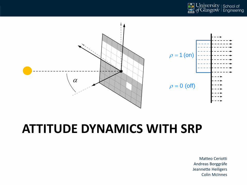
ATTITUDE DYNAMICS WITH SRP
Matteo CeriottiAndreas BorggräfeJeannette Heiligers
Colin McInnes
1 (on)
0 (off)
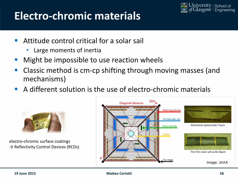
Electro-chromic materials
Attitude control critical for a solar sail• Large moments of inertia
Might be impossible to use reaction wheels
Classic method is cm-cp shifting through moving masses (and mechanisms)
A different solution is the use of electro-chromic materials
electro-chromic surface coatings→ Reflectivity Control Devices (RCDs)
Image: JAXA
19 June 2015 Matteo Ceriotti 56
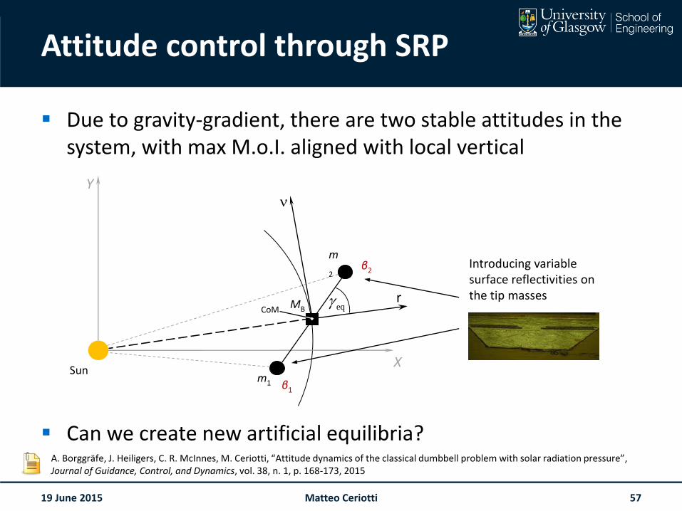
Attitude control through SRP
Due to gravity-gradient, there are two stable attitudes in the system, with max M.o.I. aligned with local vertical
Can we create new artificial equilibria?
m1
m
2
Sun
CoM
Y
X
β2
β1
rMB eq
Introducing variable surface reflectivities on the tip masses
A. Borggräfe, J. Heiligers, C. R. McInnes, M. Ceriotti, “Attitude dynamics of the classical dumbbell problem with solar radiation pressure”, Journal of Guidance, Control, and Dynamics, vol. 38, n. 1, p. 168-173, 2015
19 June 2015 Matteo Ceriotti 57
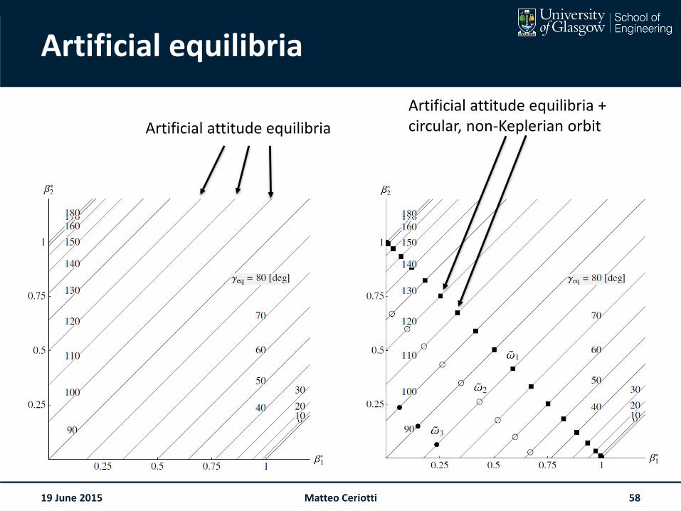
Artificial equilibria
19 June 2015 Matteo Ceriotti 58
Artificial attitude equilibria + circular, non-Keplerian orbitArtificial attitude equilibria
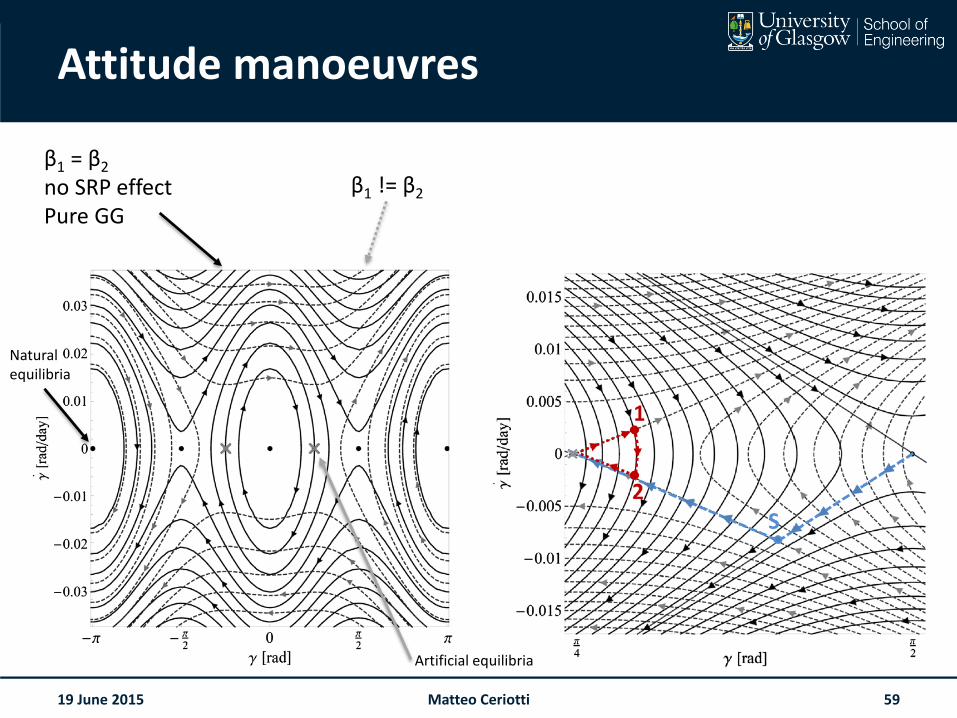
Attitude manoeuvres
19 June 2015 Matteo Ceriotti 59
β1 = β2
no SRP effectPure GG
β1 != β2
Natural equilibria
Artificial equilibria
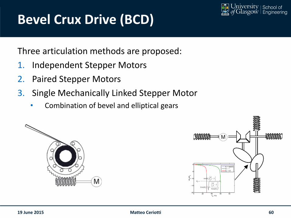
Bevel Crux Drive (BCD)
Three articulation methods are proposed:
1. Independent Stepper Motors
2. Paired Stepper Motors
3. Single Mechanically Linked Stepper Motor• Combination of bevel and elliptical gears
19 June 2015
2
2
22
22
2
sin 2
2
2cos 14cos
A
B A
A
A
b
l
b
l
Matteo Ceriotti 60
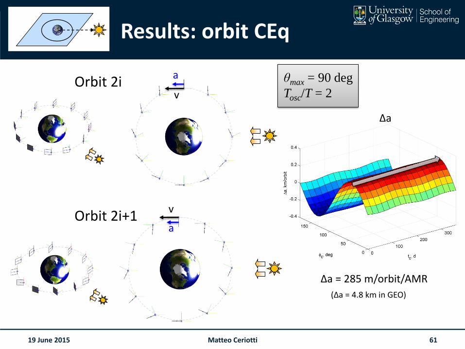
Results: orbit CEq
Orbit 2i
Orbit 2i+1
19 June 2015
θmax = 90 deg
Tosc/T = 2
Δa = 285 m/orbit/AMR
(Δa = 4.8 km in GEO)
Δa
a
v
a
v
Matteo Ceriotti 61
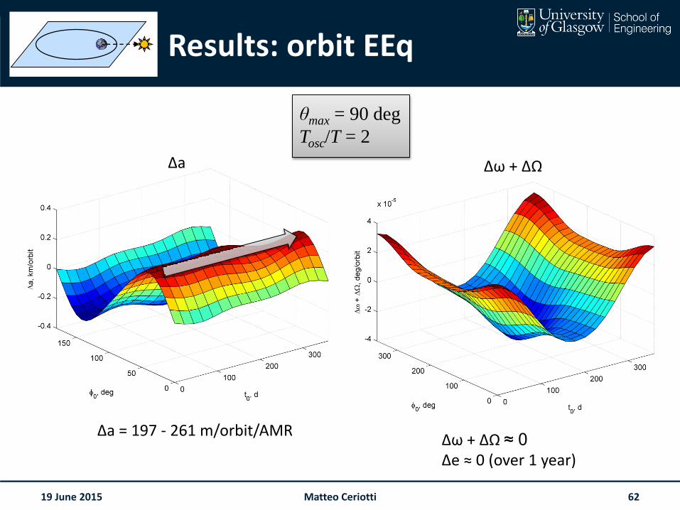
Results: orbit EEq
19 June 2015
θmax = 90 deg
Tosc/T = 2
Δa = 197 - 261 m/orbit/AMRΔω + ΔΩ ≈ 0
Δe ≈ 0 (over 1 year)
Δa Δω + ΔΩ
Matteo Ceriotti 62
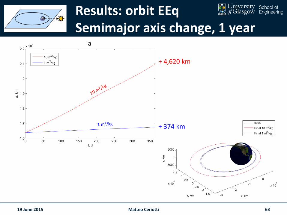
Results: orbit EEqSemimajor axis change, 1 year
19 June 2015
+ 4,620 km
+ 374 km
a
Matteo Ceriotti 63
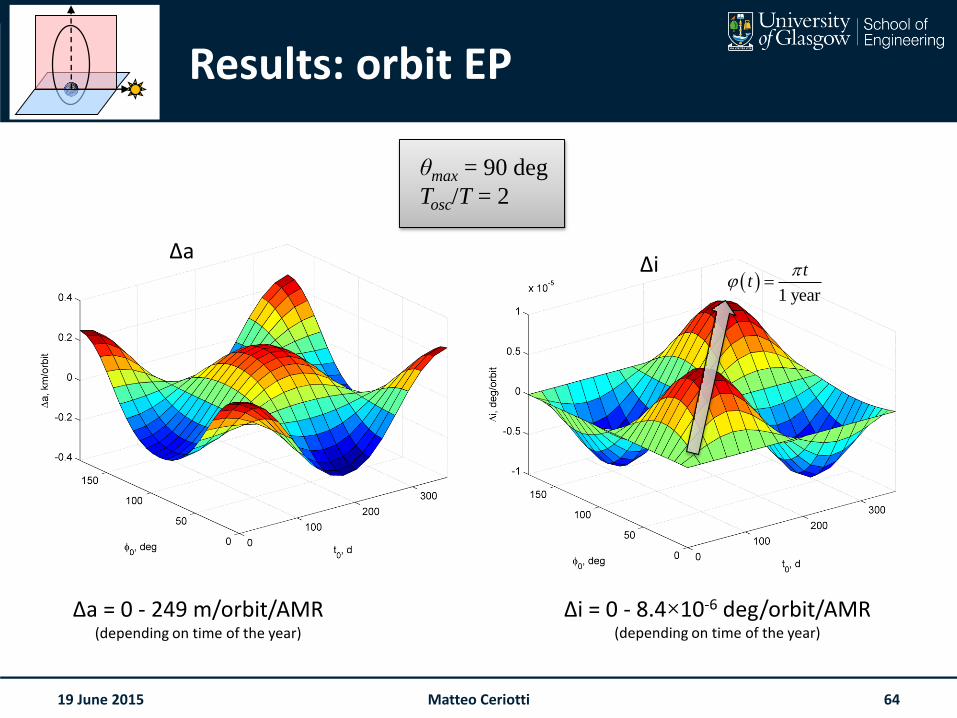
Results: orbit EP
19 June 2015
θmax = 90 deg
Tosc/T = 2
Δa = 0 - 249 m/orbit/AMR(depending on time of the year)
Δi = 0 - 8.4×10⁻⁶ deg/orbit/AMR(depending on time of the year)
1 year
tt
0
ΔaΔi
Matteo Ceriotti 64
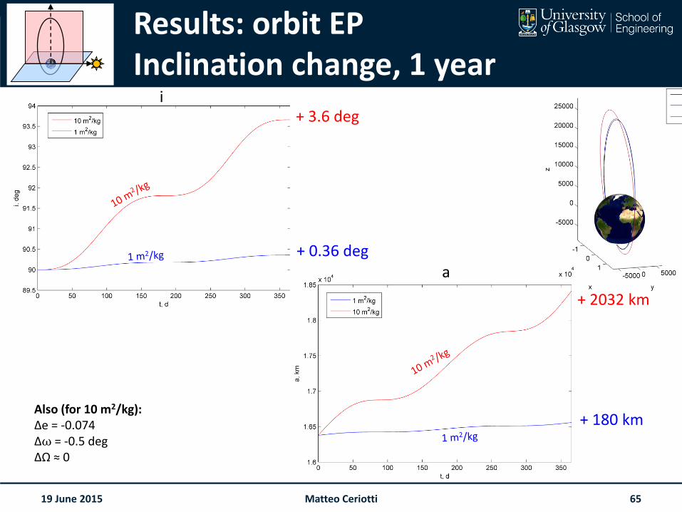
Results: orbit EPInclination change, 1 year
xzzz
19 June 2015
0
+ 3.6 deg
+ 0.36 deg
+ 2032 km
+ 180 kmAlso (for 10 m2/kg):Δe = -0.074Δω = -0.5 degΔΩ ≈ 0
a
i
Matteo Ceriotti 65