Embed Size (px)
Citation preview
Unconventional P&A (Phase 1) by bullheading a
combination of gasified and foamed fluids in a
deepwater gas well
Marcelo Victor Tomaz de Matos
Rafael Peralta Muniz Moreira
__INTRODUCTION
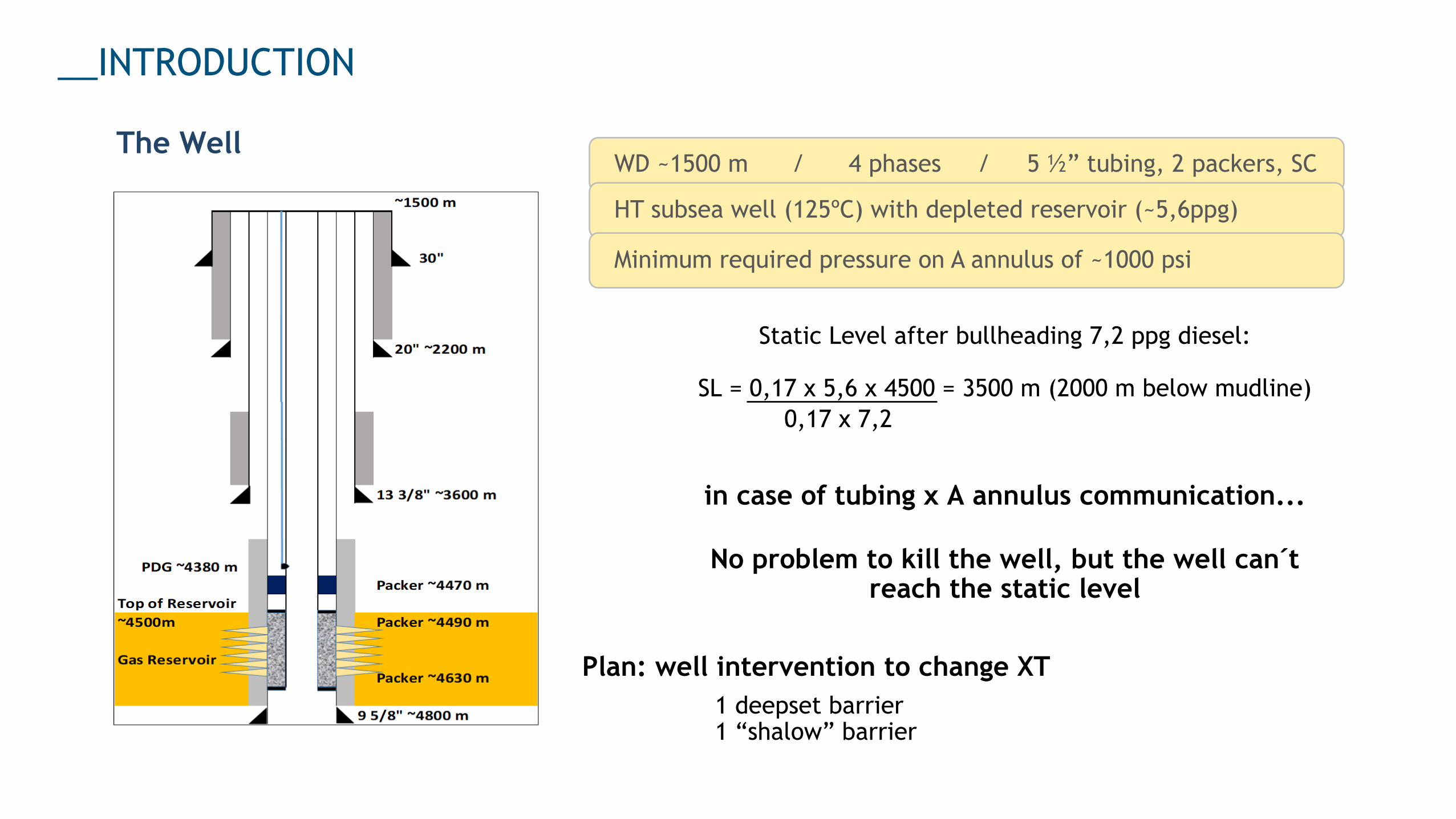
WD ~1500 m / 4 phases / 5 ½” tubing, 2 packers, SC
HT subsea well (125ºC) with depleted reservoir (~5,6ppg)
Minimum required pressure on A annulus of ~1000 psi
The Well
Static Level after bullheading 7,2 ppg diesel:
SL = 0,17 x 5,6 x 4500 = 3500 m (2000 m below mudline)
0,17 x 7,2
in case of tubing x A annulus communication...
No problem to kill the well, but the well can´treach the static level
Plan: well intervention to change XT
1 deepset barrier1 “shalow” barrier
Investigation Planning & Preparation Verif.
__INTRODUCTION
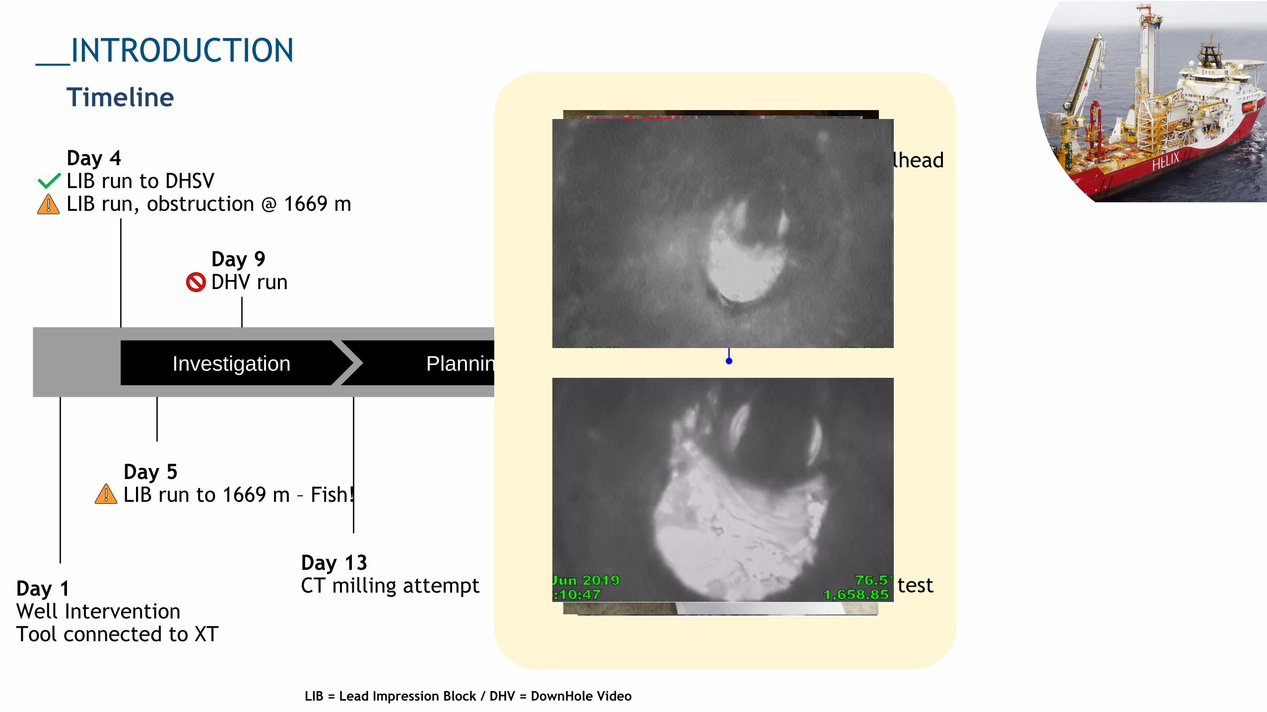
LIB = Lead Impression Block / DHV = DownHole Video
Timeline
Day 13CT milling attemptDay 1
Well InterventionTool connected to XT
Day 5LIB run to 1669 m – Fish!
Day 9DHV run
Day 51Cement plug test
Day 49Execution: Cement bullheadoperation
Day 4LIB run to DHSVLIB run, obstruction @ 1669 m
~1500 m
30"
Top of Colapse
~1650 m
20" ~2200 m
??
13 3/8" ~3600 m
PDG ~4380 m
Packer ~4470 m
Top of Reservoir
~4500m Packer ~4490 m
Gas Reservoir
Packer ~4630 m
9 5/8" ~4800 m
__INTRODUCTION
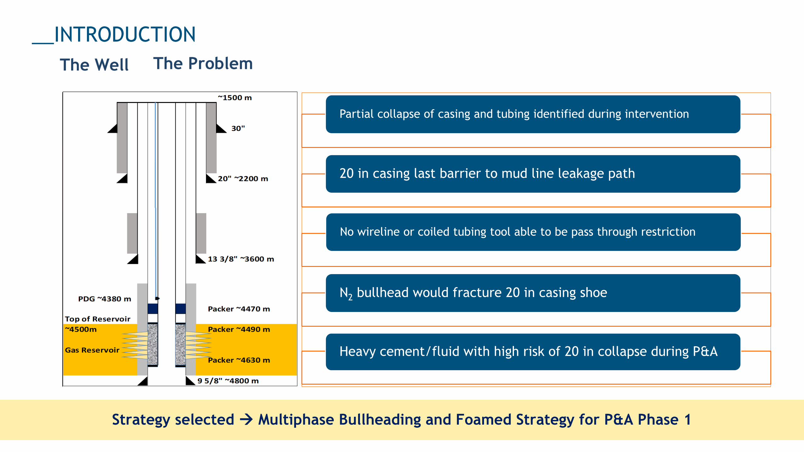
Partial collapse of casing and tubing identified during intervention
20 in casing last barrier to mud line leakage path
No wireline or coiled tubing tool able to be pass through restriction
N2 bullhead would fracture 20 in casing shoe
Heavy cement/fluid with high risk of 20 in collapse during P&A
Strategy selected → Multiphase Bullheading and Foamed Strategy for P&A Phase 1
The ProblemThe Well
Strategy selected → Multiphase Bullheading and Foamed Strategy for P&A Phase 1
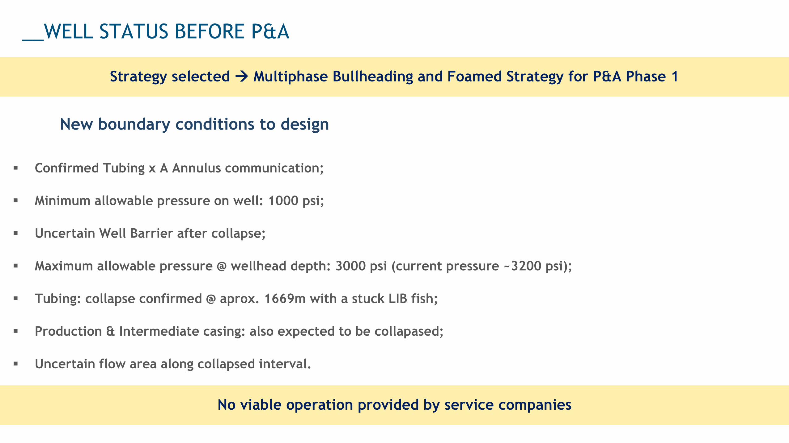
__WELL STATUS BEFORE P&A
New boundary conditions to design
▪ Confirmed Tubing x A Annulus communication;
▪ Minimum allowable pressure on well: 1000 psi;
▪ Uncertain Well Barrier after collapse;
▪ Maximum allowable pressure @ wellhead depth: 3000 psi (current pressure ~3200 psi);
▪ Tubing: collapse confirmed @ aprox. 1669m with a stuck LIB fish;
▪ Production & Intermediate casing: also expected to be collapased;
▪ Uncertain flow area along collapsed interval.
No viable operation provided by service companies
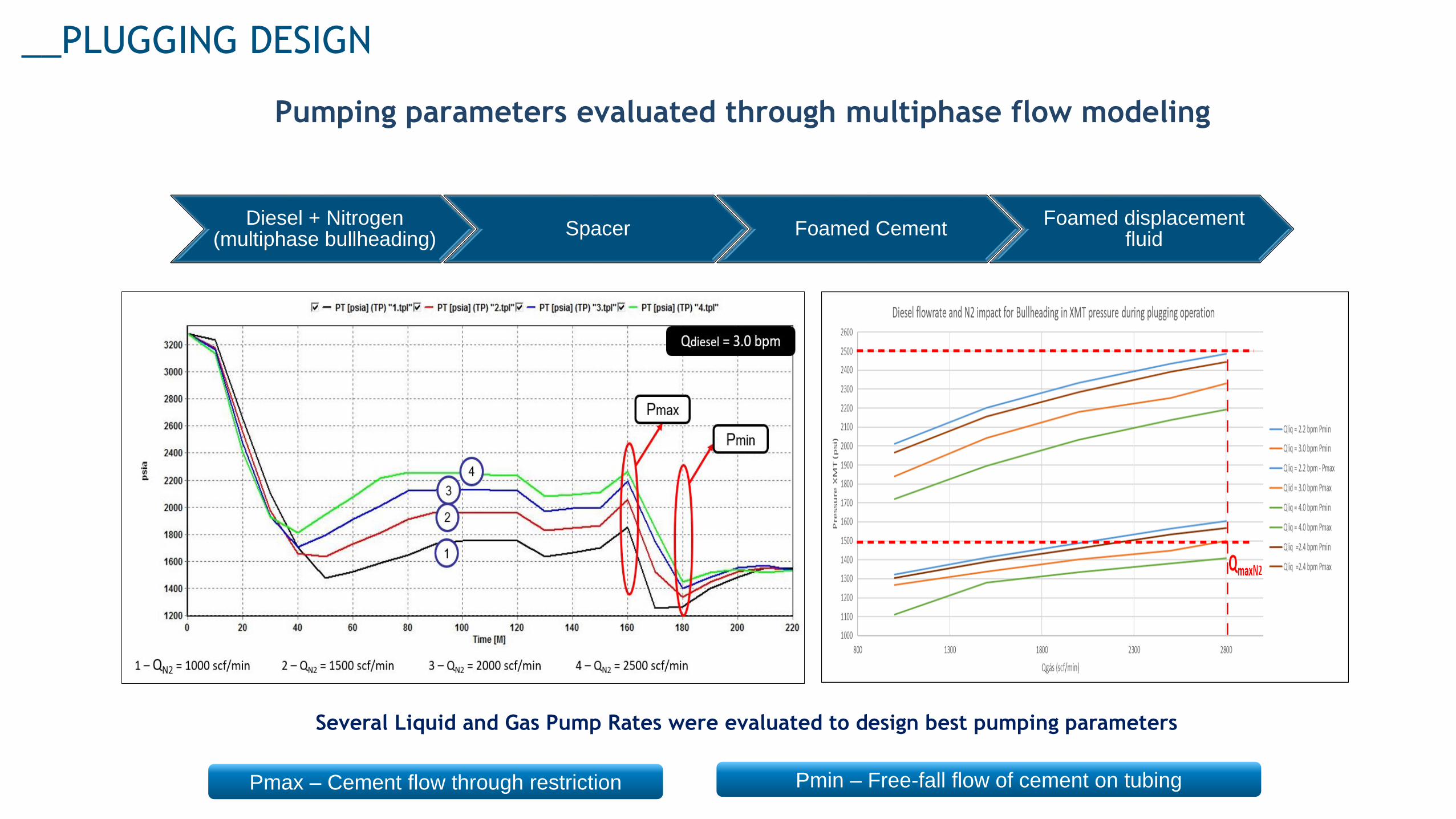
__PLUGGING DESIGN
Pumping parameters evaluated through multiphase flow modeling
Several Liquid and Gas Pump Rates were evaluated to design best pumping parameters
Diesel + Nitrogen(multiphase bullheading)
Spacer Foamed CementFoamed displacement
fluid
Pmax – Cement flow through restriction Pmin – Free-fall flow of cement on tubing
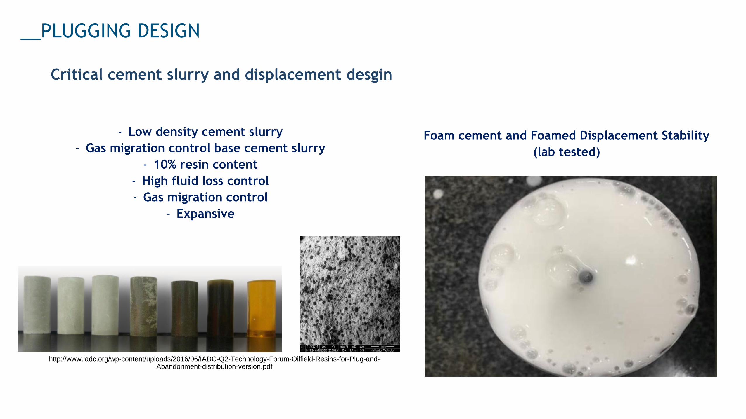
__PLUGGING DESIGN
Critical cement slurry and displacement desgin
- Low density cement slurry
- Gas migration control base cement slurry
- 10% resin content
- High fluid loss control
- Gas migration control
- Expansive
Foam cement and Foamed Displacement Stability
(lab tested)
http://www.iadc.org/wp-content/uploads/2016/06/IADC-Q2-Technology-Forum-Oilfield-Resins-for-Plug-and-Abandonment-distribution-version.pdf
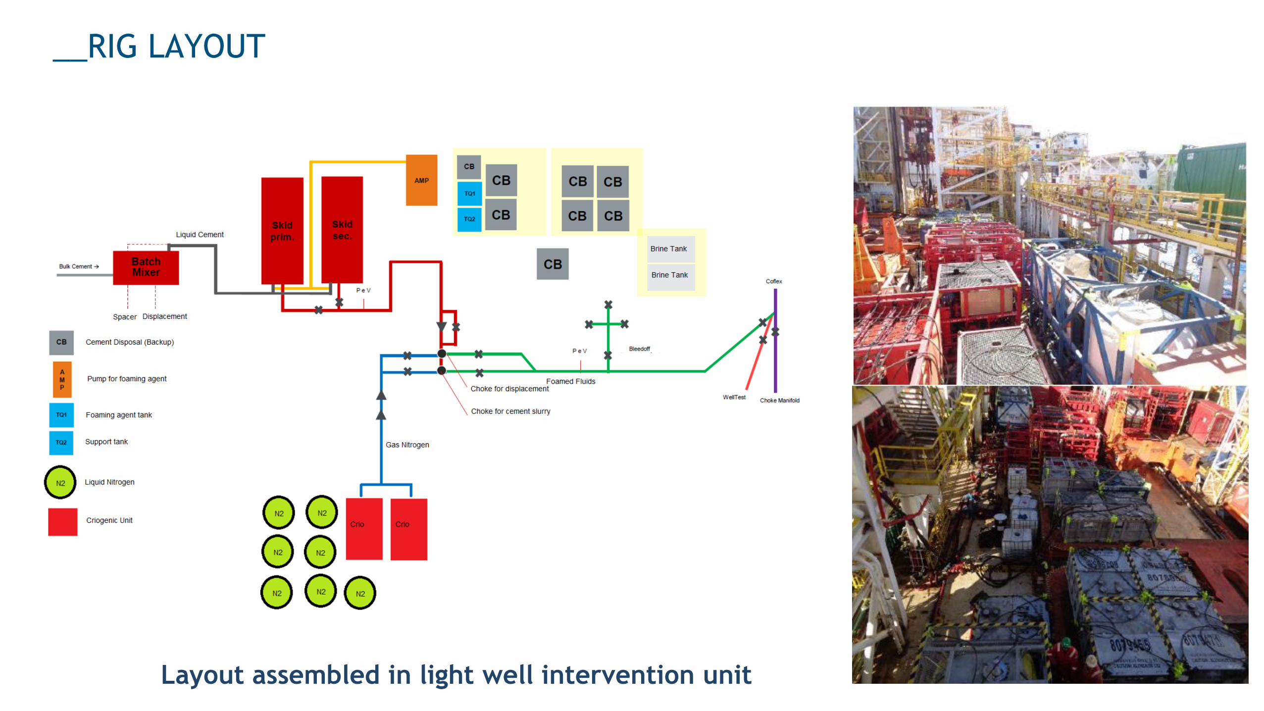
__RIG LAYOUT
Layout assembled in light well intervention unit
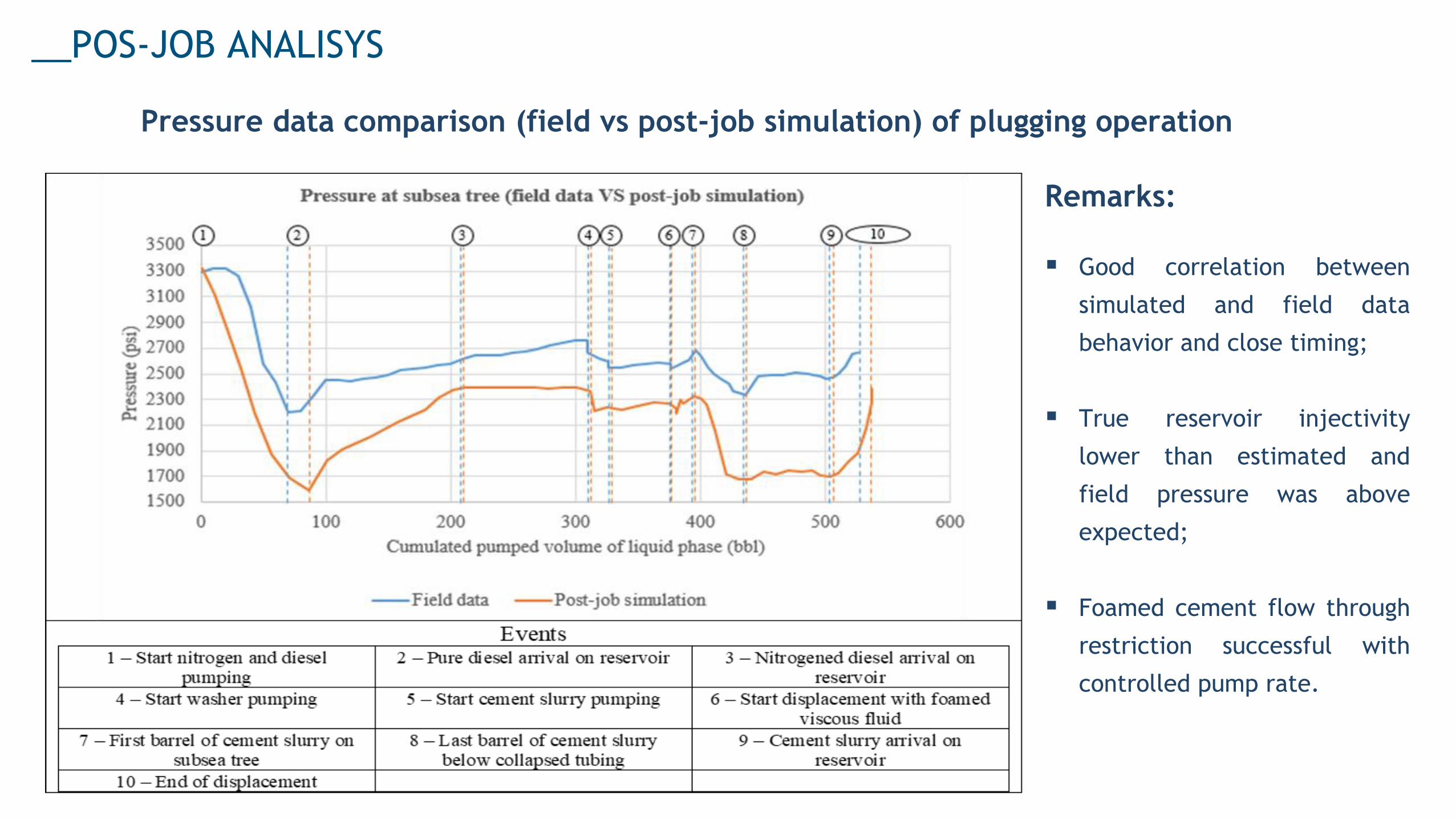
__POS-JOB ANALISYS
Pressure data comparison (field vs post-job simulation) of plugging operation
Remarks:
▪ Good correlation between
simulated and field data
behavior and close timing;
▪ True reservoir injectivity
lower than estimated and
field pressure was above
expected;
▪ Foamed cement flow through
restriction successful with
controlled pump rate.
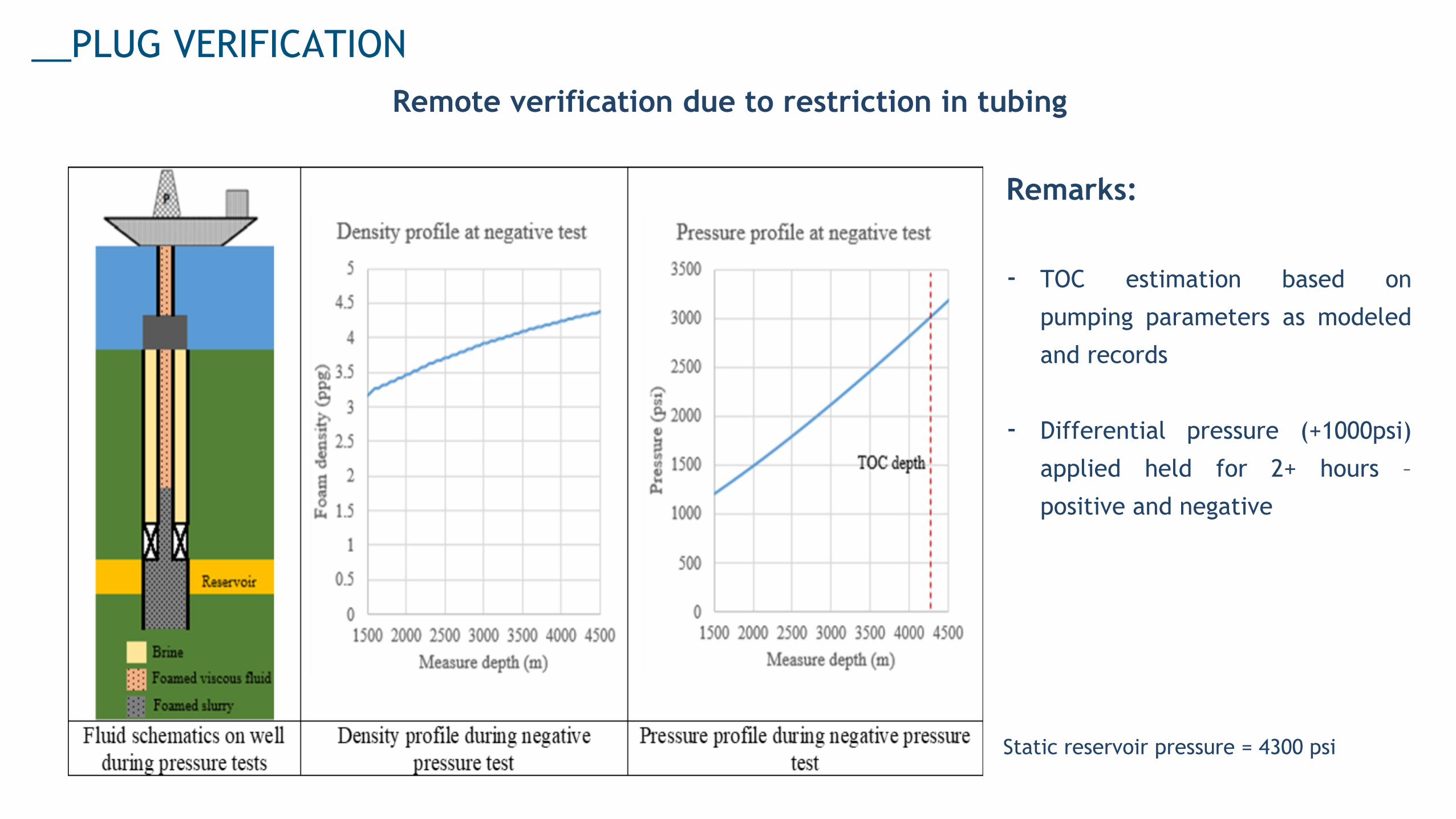
__PLUG VERIFICATION
Remote verification due to restriction in tubing
Remarks:
- TOC estimation based on
pumping parameters as modeled
and records
- Differential pressure (+1000psi)
applied held for 2+ hours –
positive and negative
Static reservoir pressure = 4300 psi
• Successful and useful modeling for bullheading with multiphase fluids and foamed cement
and displacement;
• Successful isolation achieved verified by both negative and pressure tests and pumping
parameters;
• Extremely valuable information provided by both XT sensors for the control of pumping
parameters;
• Well in safe conditions for phase 2 P&A;
• There is opportunity to develop / improve simulation capabilities for challenging P&A
operations.
__CONCLUSIONS

THANK YOU
Marcelo Victor Tomaz de Matos
Rafael Peralta Muniz Moreira