Embed Size (px)
Citation preview
Uncompromising safety and comfortThe next MCB generation within the proved System pro M compact®
2 2CDC 002 026 B0204
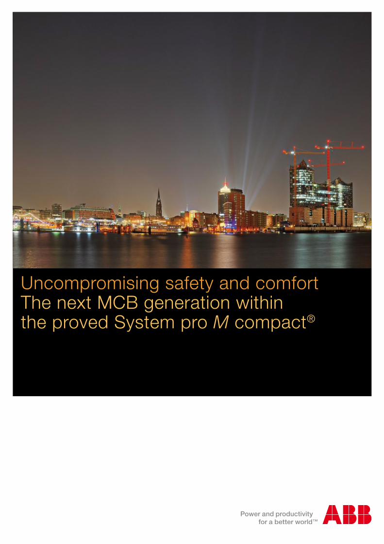
In 1923, Hugo Stotz combined a thermal and a magnetic trip unit in a single device and thereby invented a new and innovative circuit breaker, which was a revolution in electrical installation. As it could simply be screwed into usual fuse sockets it was a big success for the company, which is located in Germany for more than 120 years.
In 1923 the first of its kind – today the best. Our miniature circuit breaker MCB S 200 and S 200 M
2CDC 002 026 B0204 3
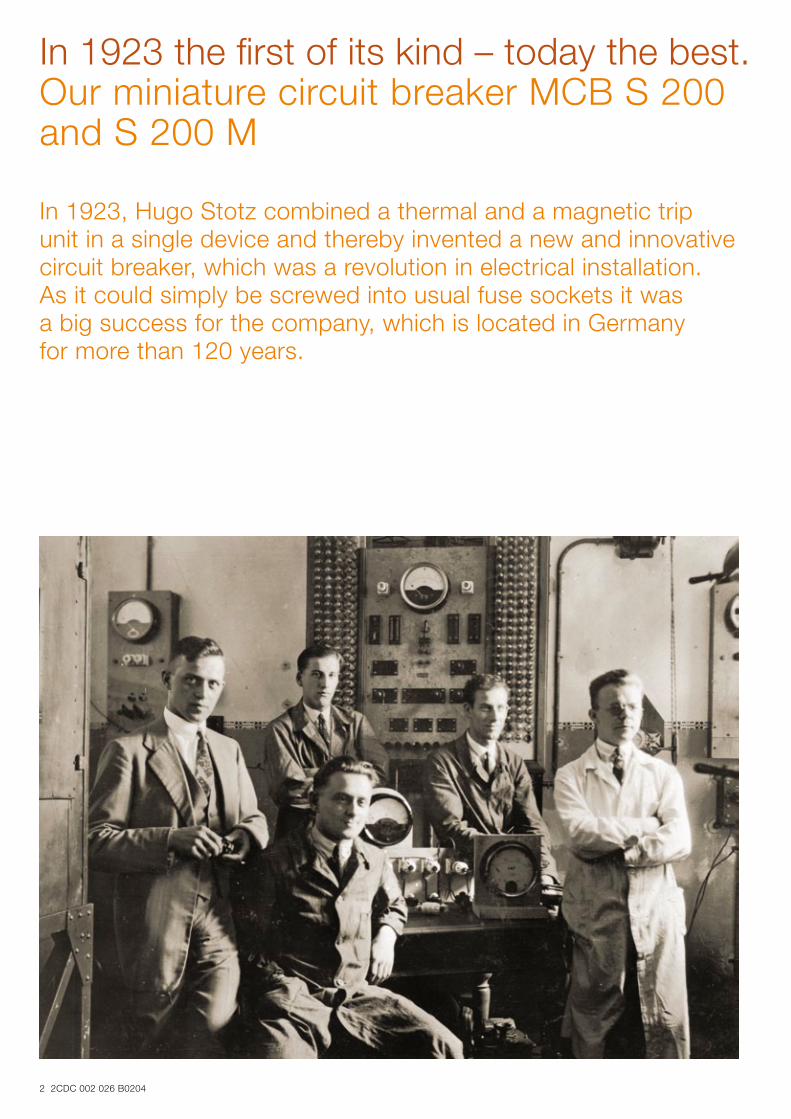
Easy product coding – easy identification: basic technical information already integrated into the name
New, patented twin terminals with captive screws: highest comfort, safety and flexibility
Laser printing: scratch and solvent resistant marking
Immediate system availability after fault by simply switching on the MCB, even by unskilled people
High rated voltage with same performance
Real contact position indication, directly connec-ted to the moving contact, for more comfort and safety
New, patented housing design: environmental friendly and performance-optimized
Patented tripping device: uncompromising safety
A range designed to ensure efficiency and protectionOur MCBs are advanced for more than 120 years in the history and mindset of Hugo Stotz. Today we offer feasible MCB solutions for all kind of applications, which are developed in close touch to market requirements from various branches.
Facts which speak for themselvesNumerous patents have been made during this time and ensure our market position as the “original” and innovation leader.
Terminal: The extended terminal size with insulating part for IP20 protection and the new pressure plate for improved conductor connection facilitate the handling and increase safety.
Switching mechanism: A new functional design and the assembly of the switching mechanism was developed to increase the reliability of triggering even under tough conditions.
Design of contacts: Contact design with snap action mechanism for improved arc movement and for an opti-mized switching behavior. Tripping device: Optimized arrangement of the thermal and electromagnetic tripping device in consideration of the arc extinguishing system to improve safety.
4 2CDC 002 026 B0204
The details make the differenceMiniature circuit-breakers MCB S 200
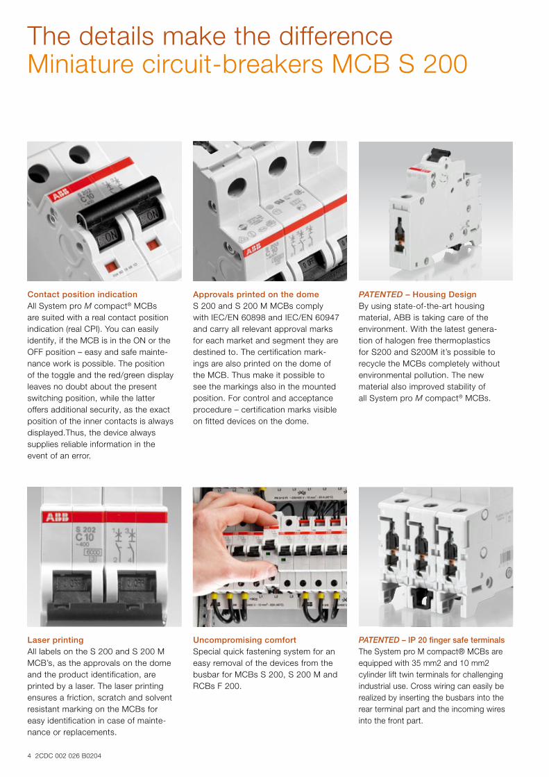
Contact position indication All System pro M compact® MCBs are suited with a real contact position in dication (real CPI). You can easily identify, if the MCB is in the ON or the OFF position – easy and safe mainte-nance work is possible. The position of the toggle and the red/green display leaves no doubt about the present switching position, while the latter offers additional security, as the exact position of the inner contacts is always displayed.Thus, the device always supplies reliable information in the event of an error.
Approvals printed on the dome S 200 and S 200 M MCBs comply with IEC/EN 60898 and IEC/EN 60947 and carry all relevant approval marks for each market and segment they are destined to. The certification mark-ings are also printed on the dome of the MCB. Thus make it possible to see the markings also in the mounted position. For control and acceptance procedure – certification marks visible on fitted devices on the dome.
PATENTED – Housing Design By using state-of-the-art housing material, ABB is taking care of the envi ronment. With the latest genera-tion of halogen free thermoplastics for S200 and S200M it’s possible to recycle the MCBs completely without environmental pollution. The new material also improved stability of all System pro M compact® MCBs.
Laser printing All labels on the S 200 and S 200 M MCB’s, as the approvals on the dome and the product identification, are printed by a laser. The laser printing ensures a friction, scratch and solvent resistant marking on the MCBs for easy identification in case of mainte-nance or replacements.
Uncompromising comfort Special quick fastening system for an easy removal of the devices from the busbar for MCBs S 200, S 200 M and RCBs F 200.
PATENTED – IP 20 finger safe terminalsThe System pro M compact® MCBs are equipped with 35 mm2 and 10 mm2 cylinder lift twin terminals for challenging industrial use. Cross wiring can easily be realized by inserting the busbars into the rear terminal part and the incoming wires into the front part.
2CDC 002 026 B0204 5
Worldwide approved S 200 / S 200 M meet all international standards
The next generation MCB S 200 / S 200 M product range provides highest safety solutions for the installer according to all relevant standards worldwide.
Besides the fact that the MCBs meet worldwide standards it is helpful if your business is global, because you can use the same basic technology throughout the world for nearly every application and installation type. And with the com-prehensive range of additional products in the System pro M compact® you can solve every task in elec trical installation.
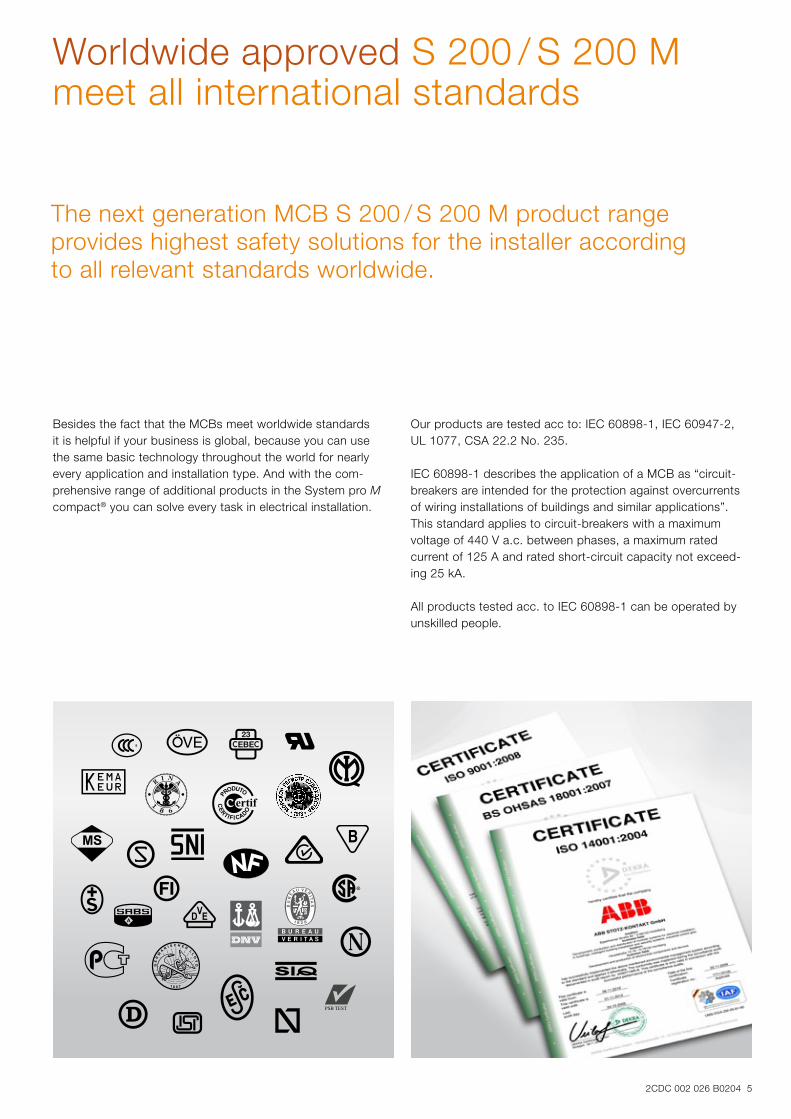
Our products are tested acc to: IEC 60898-1, IEC 60947-2, UL 1077, CSA 22.2 No. 235.
IEC 60898-1 describes the application of a MCB as “circuit-breakers are intended for the protection against overcurrents of wiring installations of buildings and similar applications”. This standard applies to circuit-breakers with a maximum voltage of 440 V a.c. between phases, a maximum rated current of 125 A and rated short-circuit capacity not exceed-ing 25 kA.
All products tested acc. to IEC 60898-1 can be operated by unskilled people.
6 2CDC 002 026 B0204
Clear and strong Definitions acc. to standards for Circuit Breakers
Rated insulation voltage (Ui) according IEC/EN 60664-1:R.M.S. withstand voltage value assigned by the manufac-turer to the equipment or to a part of it, characterizing the specified (long-term) withstand capability of its insulation.
NOTE: The rated insulation voltage is not necessarily equal to the rated voltage of the equipment which is primarily related to functional performance.
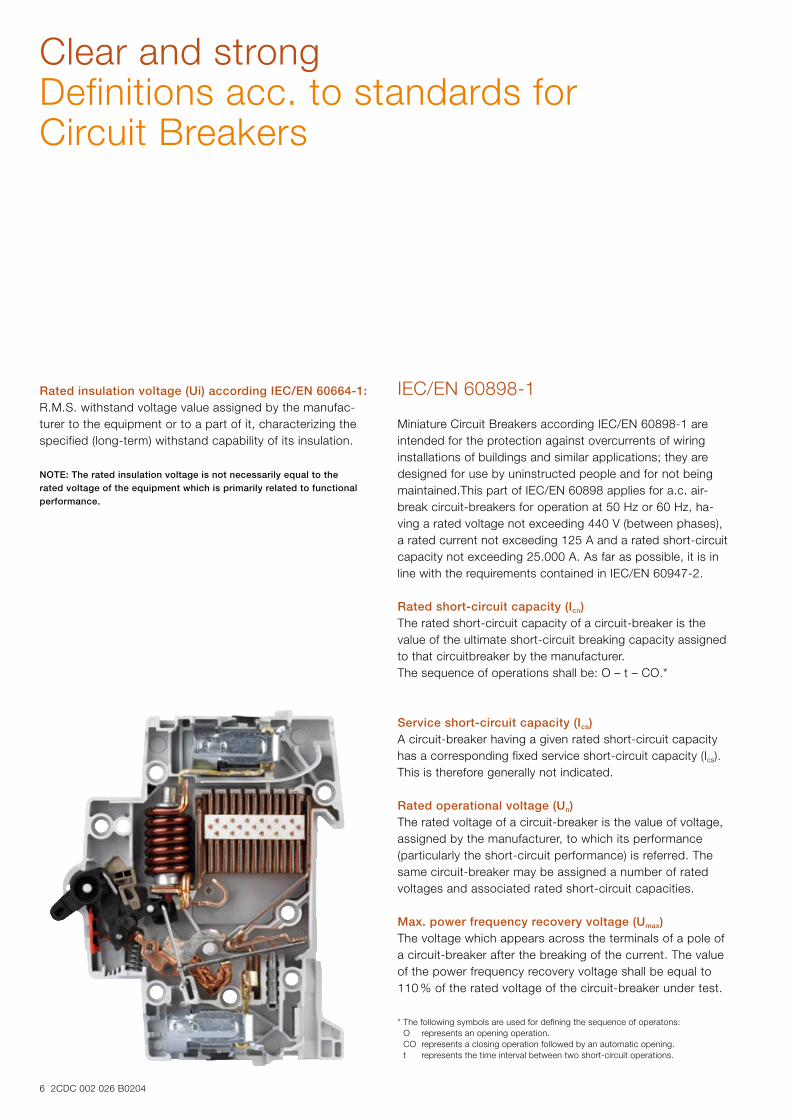
IEC/EN 60898-1 Miniature Circuit Breakers according IEC/EN 60898-1 are intended for the protection against overcurrents of wiring installations of buildings and similar applications; they are designed for use by uninstructed people and for not being maintained.This part of IEC/EN 60898 applies for a.c. air-break circuit-breakers for operation at 50 Hz or 60 Hz, ha-ving a rated voltage not exceeding 440 V (between phases), a rated current not exceeding 125 A and a rated short-circuit capacity not exceeding 25.000 A. As far as possible, it is in line with the requirements contained in IEC/EN 60947-2.
Rated short-circuit capacity (Icn)The rated short-circuit capacity of a circuit-breaker is the value of the ultimate short-circuit breaking capacity assigned to that circuitbreaker by the manufacturer. The sequence of operations shall be: O – t – CO.*
Service short-circuit capacity (Ics)A circuit-breaker having a given rated short-circuit capacity has a corresponding fixed service short-circuit capacity (Ics).This is therefore generally not indicated.
Rated operational voltage (Un)The rated voltage of a circuit-breaker is the value of voltage,assigned by the manufacturer, to which its performance (particularly the short-circuit performance) is referred. The same circuit-breaker may be assigned a number of rated voltages and associated rated short-circuit capacities.
Max. power frequency recovery voltage (Umax)The voltage which appears across the terminals of a pole of a circuit-breaker after the breaking of the current. The value of the power frequency recovery voltage shall be equal to 110 % of the rated voltage of the circuit-breaker under test.
* The following symbols are used for defining the sequence of operatons: O represents an opening operation. CO represents a closing operation followed by an automatic opening. t represents the time interval between two short-circuit operations.
2CDC 002 026 B0204 7
IEC/EN 60947-2
This part of the IEC/EN 60947 applies to circuit-breakers, the main contacts of which are intended to be connected to circuits, the rated voltage of which does not exceed 1.000 V a.c. or 1.500 V d.c.. It applies whatever the rated currents, the method of construction or the proposed applications of the circuit-breakers may be. The circuit-breakers are designed for use by instructed people.
Rated ultimate short-circuit breaking capacity Icu
The rated ultimate short-circuit breaking capacity of a circuit-breaker is the value of ultimate short-circuit breaking capacity assigned to that circuit-breaker by the manufacturer for the corresponding rated operational voltage. It is expressed as the value of the prospective breaking current, in kA (r.m.s. value of the a.c. component in the case of a.c.). The sequence of operations shall be: O – t – CO.*
Rated service short-circuit breaking capacity Ics
The rated service short-circuit breaking capacity of a circuit-breaker is the value of service short-circuit breaking capacity assigned to that circuit-breaker by the manufacturer for the cor-responding rated operational voltage. It is expressed as a value of prospective breaking current, in kA, corresponding to one of the specified percentages of the rated ultimate short-circuit breaking capacity and rounded up to the nearest whole number. It may be expressed as a % of Icu (for example Ics = 25 % Icu). The sequence of operations shall be: O – t – CO – t – CO.*
Rated operational voltage (Ue)The rated operational voltage of an equipment is a value of voltage which, combined with a rated operational current, determines theapplication of the equipment and to which the relevant tests and the utilization categories are referred. For single-pole equipment it is generally stated as the voltage across the pole. For multi pole equipment it is generally stated as the voltage between phases. An equipment my be assigned a number of combinations of rated operational voltage and associated making and breaking capacities for different duties and utilization categories.
Max. power frequency recovery voltage (Umax)Voltage which appears across the terminals of a pole of a switching device after the breaking of the current. For all breaking capacities and short-circuit breaking capacity tests, the value of the power-frequency recovery voltage shall be 105 % of the value of the rated operational voltage. This value shall be within the specified tolerance (voltage 0 / + 5%).
NOTE: The value of 1.05 times the rated operational voltage for the power frequency recovery voltage, together with the test voltage tolerance resulting in a maximum voltage of 1.1 times the rated operational voltage, is deemed to cover the effects of variations of the system voltage under normal service conditions.
UL 489 The requirements of this standard cover molded-case circuit breakers, circuit breaker and ground-fault circuit-interrupters, fused circuit breakers, and accessory high-fault protectors. These circuit breakers are specifically intended to provide service entrance, feeder, and branch circuit protection in accordance with the National Installation Codes in Annex B, Ref. No.1. This standard also covers instantaneous-trip circuit breakers (circuit interrupters) specifically intended for use as part of a combination motor controller in accordance with the National Installation Codes in Annex B, Ref. No. 1.
UL 1077
These requirements apply to supplementary protectors intended for use as overcurrent, or over- or under-voltage protection within an appliance or other electrical equipment where branch circuit overcurrent protection is already pro-vided, or is not required. Compliance with this standard is acceptable for use as a component of an end product.
8 2CDC 002 026 B0204
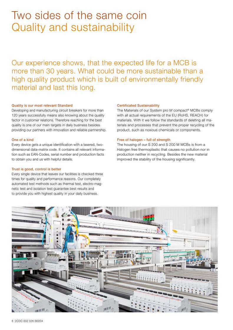
Two sides of the same coinQuality and sustainability
Our experience shows, that the expected life for a MCB is more than 30 years. What could be more sustainable than a high quality product which is built of environmentally friendly material and last this long.
Quality is our most relevant StandardDeveloping and manufacturing circuit breakers for more than 120 years successfully means also knowing about the quality factor in customer relations. Therefore reaching for the best quality is one of our main targets in daily business besides providing our partners with innovation and reliable partnership.
One of a kindEvery device gets a unique identification with a lasered, two-dimensional data-matrix code. It contains all relevant informa-tion such as EAN-Codes, serial number and production facts to obtain you and us with helpful details.
Trust is good, control is betterEvery single device that leaves our facilities is checked three times for quality and performance reasons. Our completely automated test methods such as thermal test, electro-mag- n etic test and isolation test guarantee best results and to provide you with highest quality in your daily business.
Certificated SustainabilityThe Materials of our System pro M compact® MCBs comply with all actual requirements of the EU (RoHS, REACH) for materials. With it we follow the standards of deleting all ma-terials and processes that prevent the proper recycling of the product, such as noxious chemicals or components.
Free of halogen – full of strengthThe housing of our S 200 and S 200 M MCBs is from a Halogen free thermoplastic that causes no pollution nor in production neither in recycling. Besides the new material improved the stability of the housing significantly.
2CDC 002 026 B0204 9
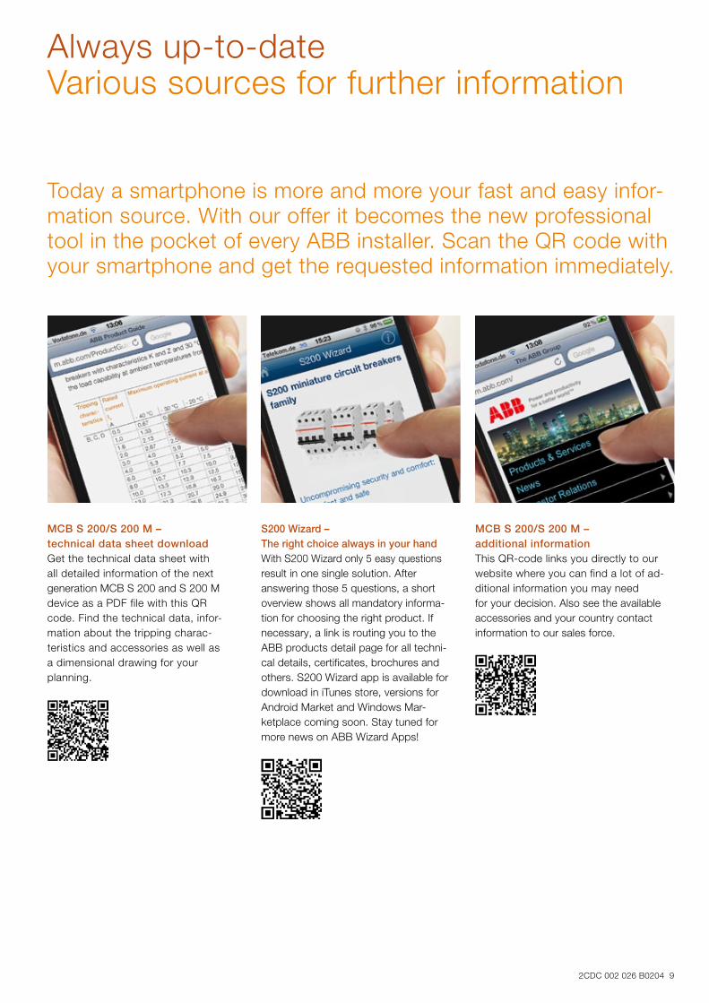
Always up-to-dateVarious sources for further information
Today a smartphone is more and more your fast and easy infor-mation source. With our offer it becomes the new professional tool in the pocket of every ABB installer. Scan the QR code with your smartphone and get the reques ted information immediately.
MCB S 200/S 200 M – technical data sheet downloadGet the technical data sheet with all detailed information of the next generation MCB S 200 and S 200 M device as a PDF file with this QR code. Find the technical data, infor-mation about the tripping charac-teristics and accessories as well as a dimen sional drawing for your planning.
S200 Wizard – The right choice always in your hand With S200 Wizard only 5 easy questions result in one single solution. After answering those 5 questions, a short overview shows all mandatory informa-tion for choosing the right product. If necessary, a link is routing you to the ABB products detail page for all techni-cal details, certificates, brochures and others. S200 Wizard app is available for download in iTunes store, versions for Android Market and Windows Mar-ketplace coming soon. Stay tuned for more news on ABB Wizard Apps!
MCB S 200/S 200 M – additional informationThis QR-code links you directly to our website where you can find a lot of ad-ditional information you may need for your decision. Also see the available accessories and your country contact information to our sales force.
All-rounders for every applicationThe comprehensive circuit breaker range
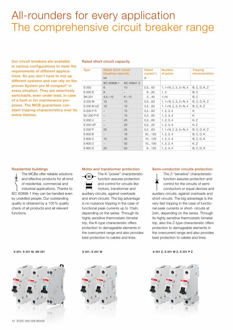
Rated short circuit capacityOur circuit breakers are available in various configurations to meet the requirements of different applica-tions. So you don’t have to mix up different systems and can rely on the proven System pro M compact® in every situation. They are selectively switchable, even under load, in case of a fault or for maintenance pur-poses. The MCB guarantees con-stant tripping-characteristics over its entire lifetime.
S 201, S 201 M, SN 201 S 201, S 201 M S 201 Z, S 201 M Z, S 201 P Z
Residential buildingsThe MCBs offer reliable solutions and effective products for all kind of residential, commercial and industrial applications. Thanks to
IEC 60898-1 they can be handled even by unskilled people. Our outstanding quality is obtained by a 100 % quality check of all products and all relevant functions.
Motor and transformer protectionThe K-”power” characteristic-function assures protection and control for circuits like motors, transformer and
auxiliary circuits, against overloads and short-circuits. The big advantage is no nuisance tripping in the case of functional peak currents up to 10xIn, depending on the series. Through its highly sensitive thermostatic bimetal trip, the K-type characteristic offers protection to damageable elements in the overcurrent range and also provides best protection to cables and lines.
Semi-conductor circuits protectionThe Z-”sensitive” characteristic-function assures protection and control for the circuits of semi-conductors or equal devices and
auxiliary circuits, against overloads and short-circuits. The big advantage is the very fast tripping in the case of functio-nal peak currents or short- circuits at 2xIn, depending on the series. Through its highly sensitive thermostatic bimetal trip, also the Z-type characteristic offers protection to damageable elements in the overcurrent range and also provides best protection to cables and lines.
Type Rated short circuit breaking capacity
Rated current In
Number of poles
Tripping characteristics
kA A
IEC 60898-1 IEC 60947-2
S 200 6 10 0,5…63 1, 1+ N, 2, 3, 3 + N, 4 B, C, D, K, Z
S 200 S 6 – 6…20 1, 3 B, C
SN 201 4,5 – 10 6 – 10 2…40 1+ N B, C
S 200 M 10 15 0,5…63 1, 1+ N, 2, 3, 3 + N, 4 B, C, D, K, Z
S 200 M UC 10 10 0,5…63 1, 1+ N, 2, 3, 3 + N, 4 B, C, K, Z
S 200 P R – 15 0,2…63 1, 2, 3, 4 K
SU 200 P R – 15 0,2…63 1, 2, 3, 4 K
S 200 U – 25 0,2…63 1, 2, 3, 4 K, Z
S 200 UP – 25 0,2…25 1, 2, 3, 4 K, Z
S 200 P 25 25 0,2…63 1, 1+ N, 2, 3, 3 + N, 4 B, C, D, K, Z
S 800 B – 16 32…125 1, 2, 3, 4 B, C, D, K
S 800 C 15 25 10…125 1, 2, 3, 4 B, C, D, K
S 800 U – 50 10…100 1, 2, 3, 4 K, Z
S 800 S 25 50 6…125 1, 2, 3, 4 B, C, D, K
10 2CDC 002 026 B0204
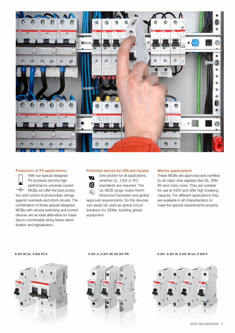
S 201 M UC, S 802 PV S S 201 U, S 201 UP, SU 201 PR S 201, S 201 M, S 201 M UC, S 200 P
Protection of PV applicationsWith our special designed PV products and the high performance universal current MCBs we offer the best protec-
tion and control of photovoltaic strings against overloads and short-circuits. The combination of those special designed MCBs with remote switching and control devices are an ideal alternative for fuses due to comfortable string failure identi-fication and signalization.
Protection devices for USA and CanadaOne solution for all applications,whether UL, CSA or IEC standards are required. The UL MCB range meets North American/Canadian and global
approval requirements. So the devices can easily be used as global circuit breakers for OEMs, building global equipment.
Marine applicationsThese MCBs are approved and certified by all major ship registers like GL, DNV, BV and many more. They are suitable for use at 440V and offer high breaking capacity. For different applications they are available in all characteristics to meet the special requirements properly.
2CDC 002 026 B0204 11
12 2CDC 002 026 B0204
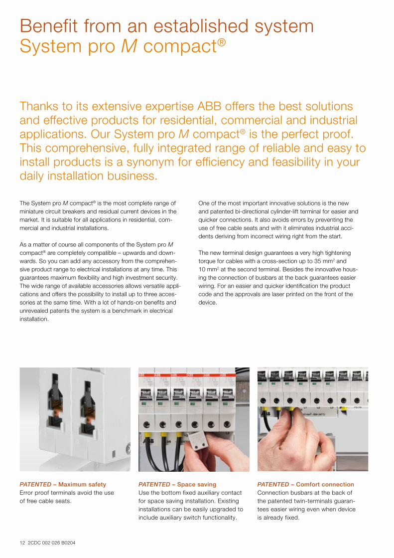
Benefit from an established systemSystem pro M compact®
Thanks to its extensive expertise ABB offers the best solutions and effective products for residential, commercial and industrial applications. Our System pro M compact® is the perfect proof. This comprehensive, fully integrated range of reliable and easy to install products is a synonym for efficiency and feasibility in your daily installation business.
The System pro M compact® is the most complete range of miniature circuit breakers and residual current devices in the market. It is suitable for all applications in residential, com-mercial and industrial installations.
As a matter of course all components of the System pro M compact® are completely compatible – upwards and down-wards. So you can add any accessory from the comprehen-sive product range to electrical installations at any time. This guarantees maximum flexibility and high investment security. The wide range of available accessories allows versatile appli-cations and offers the possibility to install up to three acces-sories at the same time. With a lot of hands-on benefits and unrevealed patents the system is a benchmark in electrical installation.
One of the most important innovative solutions is the new and patented bi-directional cylinder-lift terminal for easier and quicker connections. It also avoids errors by preventing the use of free cable seats and with it eliminates industrial acci-dents deriving from incorrect wiring right from the start.
The new terminal design guarantees a very high tightening torque for cables with a cross-section up to 35 mm2 and 10 mm2 at the second terminal. Besides the innovative hous-ing the connection of busbars at the back guarantees easier wiring. For an easier and quicker identification the product code and the approvals are laser printed on the front of the device.
PATENTED – Maximum safetyError proof terminals avoid the use of free cable seats.
PATENTED – Space savingUse the bottom fixed auxiliary contact for space saving installation. Existing installations can be easily upgraded to include auxiliary switch functionality.
PATENTED – Comfort connectionConnection busbars at the back of the patented twin-terminals guaran -tees easier wiring even when device is already fixed.
2CDC 002 026 B0204 13
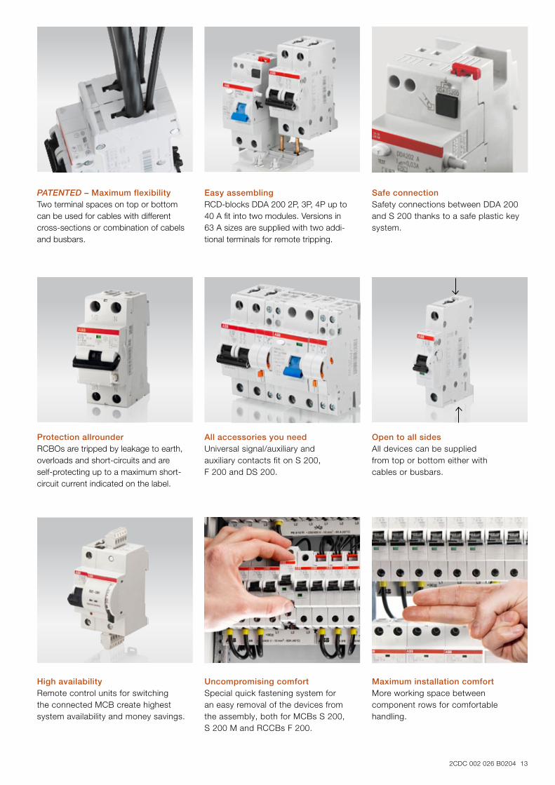
Protection allrounderRCBOs are tripped by leakage to earth, overloads and short-circuits and are self-protecting up to a maximum short-circuit current indicated on the label.
All accessories you needUniversal signal/auxiliary and auxiliary contacts fit on S 200, F 200 and DS 200.
Open to all sides All devices can be supplied from top or bottom either with cables or busbars.
High availabilityRemote control units for switching the connected MCB create highest system availability and money savings.
Uncompromising comfortSpecial quick fastening system for an easy removal of the devices from the assembly, both for MCBs S 200, S 200 M and RCCBs F 200.
Maximum installation comfort More working space between component rows for comfortable handling.
PATENTED – Maximum flexibilityTwo terminal spaces on top or bottom can be used for cables with different cross-sections or combination of cabels and busbars.
Easy assemblingRCD-blocks DDA 200 2P, 3P, 4P up to 40 A fit into two modules. Versions in 63 A sizes are supplied with two addi-tional terminals for remote tripping.
Safe connectionSafety connections between DDA 200 and S 200 thanks to a safe plastic key system.
14 2CDC 002 026 B0204
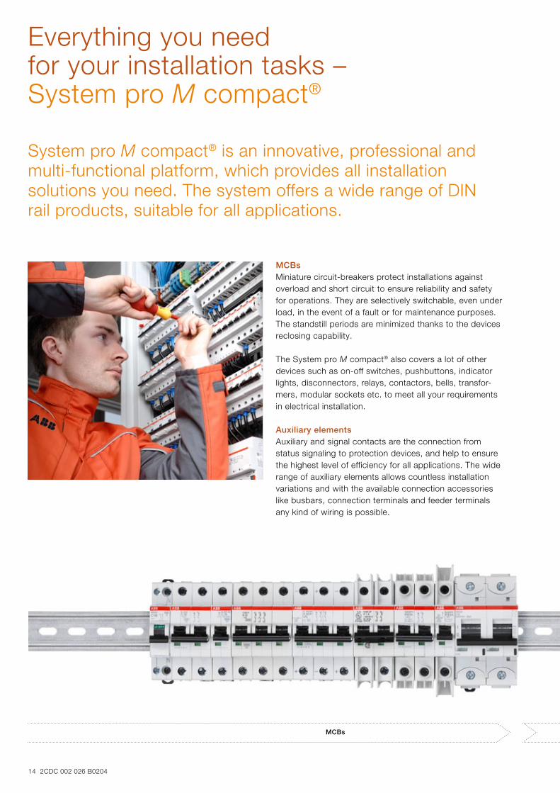
Everything you need for your installation tasks – System pro M compact®
MCBsMiniature circuit-breakers protect installations against overload and short circuit to ensure reliability and safety for operations. They are selectively switchable, even under load, in the event of a fault or for maintenance purposes. The standstill periods are minimized thanks to the devices reclosing capability.
The System pro M compact® also covers a lot of other devices such as on-off switches, pushbuttons, indicator lights, disconnectors, relays, contactors, bells, transfor-mers, modular sockets etc. to meet all your requirements in electrical installation. Auxiliary elementsAuxiliary and signal contacts are the connection from status signaling to protection devices, and help to ensure the highest level of efficiency for all applications. The wide range of auxiliary elements allows countless installation variations and with the available connection accessories like busbars, connection terminals and feeder terminals any kind of wiring is possible.
System pro M compact® is an innovative, professional and multi-functional platform, which provides all installation solutions you need. The system offers a wide range of DIN rail products, suitable for all applications.
MCBs
2CDC 002 026 B0204 15
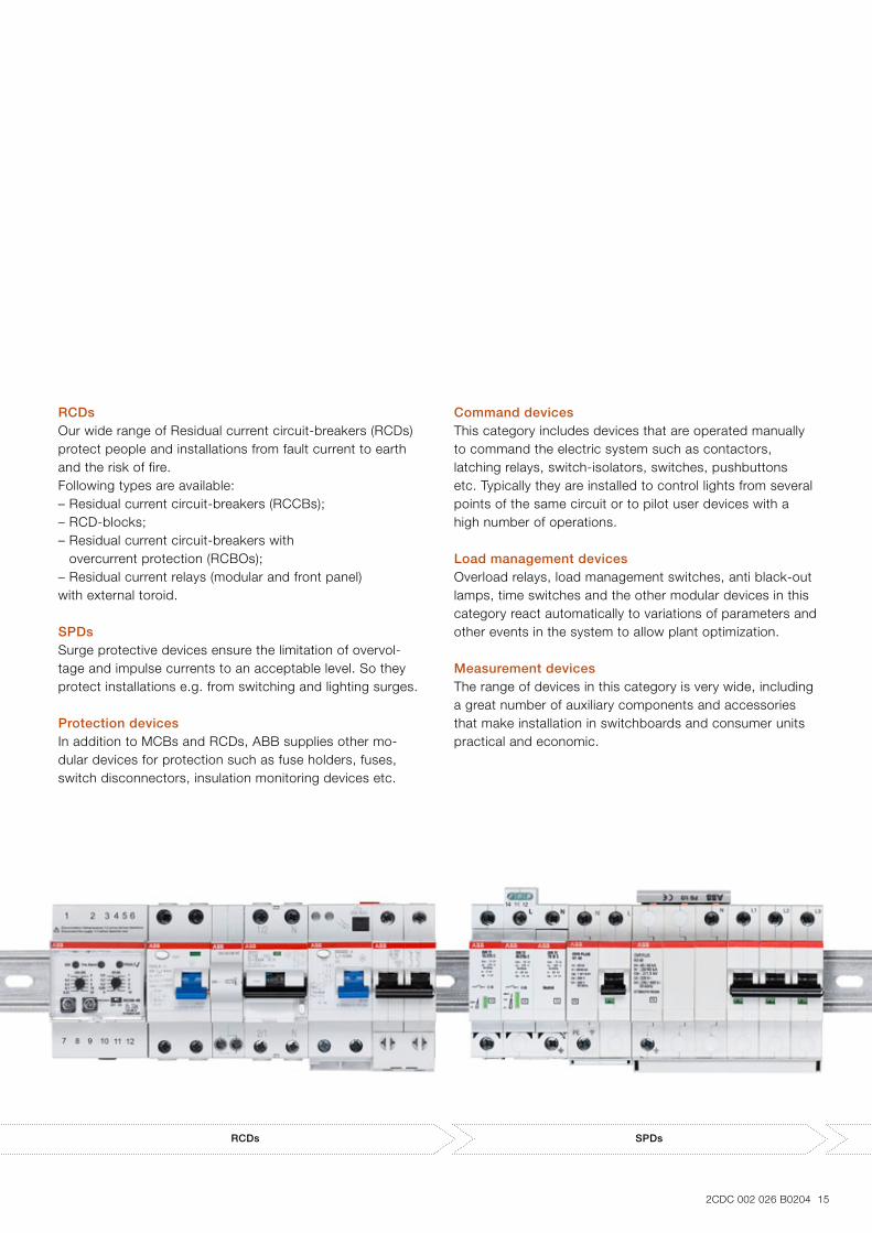
RCDsOur wide range of Residual current circuit-breakers (RCDs) protect people and installations from fault current to earth and the risk of fire. Following types are available:– Residual current circuit-breakers (RCCBs);– RCD-blocks;– Residual current circuit-breakers with
overcurrent protection (RCBOs);– Residual current relays (modular and front panel) with external toroid. SPDsSurge protective devices ensure the limitation of overvol-tage and impulse currents to an acceptable level. So they protect installations e.g. from switching and lighting surges. Protection devicesIn addition to MCBs and RCDs, ABB supplies other mo-dular devices for protection such as fuse holders, fuses, switch disconnectors, insulation monitoring devices etc.
Command devicesThis category includes devices that are operated manually to command the electric system such as contactors, latching relays, switch-isolators, switches, pushbuttons etc. Typically they are installed to control lights from several points of the same circuit or to pilot user devices with a high number of operations. Load management devicesOverload relays, load management switches, anti black-out lamps, time switches and the other modular devices in this category react automatically to variations of parameters and other events in the system to allow plant optimization.
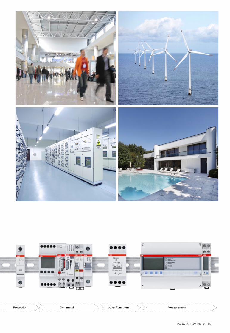
Measurement devicesThe range of devices in this category is very wide, including a great number of auxiliary components and accessories that make installation in switchboards and consumer units practical and economic.
RCDs SPDs
2CDC 002 026 B0204 16
Protection Command other Functions Measurement
18 2CDC 002 026 B0204
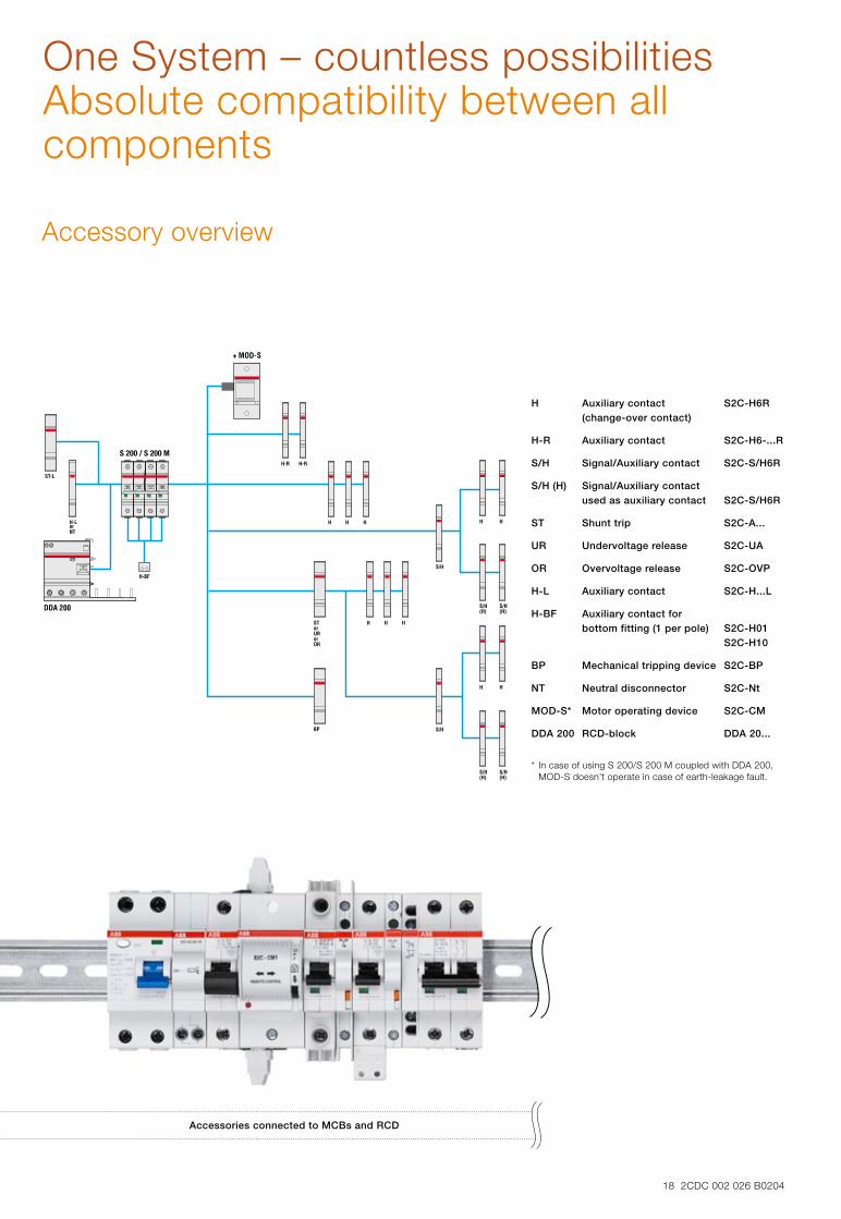
One System – countless possibilitiesAbsolute compatibility between all components
Accessories connected to MCBs and RCD
H Auxiliary contact S2C-H6R (change-over contact)
H-R Auxiliary contact S2C-H6-...R
S/H Signal/Auxiliary contact S2C-S/H6R
S/H (H) Signal/Auxiliary contact used as auxiliary contact S2C-S/H6R
ST Shunt trip S2C-A...
UR Undervoltage release S2C-UA
OR Overvoltage release S2C-OVP
H-L Auxiliary contact S2C-H...L
H-BF Auxiliary contact for bottom fitting (1 per pole) S2C-H01 S2C-H10
BP Mechanical tripping device S2C-BP
NT Neutral disconnector S2C-Nt
MOD-S* Motor operating device S2C-CM
DDA 200 RCD-block DDA 20...
* In case of using S 200/S 200 M coupled with DDA 200,
MOD-S doesn’t operate in case of earth-leakage fault.
Accessory overview
Contact us
Ord
er n
um
ber
2C
DC
002
026
B02
04 0
7/12
-pd
fABB STOTZ-KONTAKT GmbH Eppelheimer Straße 82 69123 Heidelberg, Germany Phone: +49 (0) 6221 7 01-0 Fax: +49 (0) 6221 7 01-13 25 E-Mail: [email protected] You can find the address of your local sales organization on the ABB home page http://www.abb.com/contacts -> Low Voltage Products and Systems
Note:We reserve the right to make technical changes or modify the contents of this document without prior notice. With regard to purchase orders, the agreed particulars shall prevail. ABB AG does not accept any responsibility whatsoever for potential errors or possible lack of information in this document.
We reserve all rights in this document and in the subject matter and illustrations contained therein. Any reproduction, disclosure to third parties or utilization of its contents – in whole or in parts – is forbidden without prior written consent of ABB AG.
Copyright© 2012 ABB All rights reserved