Embed Size (px)
Citation preview

Unclassified PresentationUnclassified Presentation
Julio C. G. Pimentel
IEEE
Dept. of Computer
and Electrical Engineering
Ste. Foy, Quebec, Canada
Yosef Gavriel Tirat-GefenIEEE, AIAA
Castel Research Inc.www.castelresearch.com
Fairfax, VAe-mail:
[email protected]& George Mason University
Fairfax, VA
Validation of Mission Critical Power and Control Systems
for Lunar Settlement

OverviewOverview MotivationMotivation Related WorkRelated Work Mission Critical SystemsMission Critical Systems Power Systems for Lunar SettlementPower Systems for Lunar Settlement Control Systems ValidationControl Systems Validation Solar Array Based Power System Solar Array Based Power System
ExampleExample ConclusionConclusion

MotivationMotivation Major systems to be used in the Lunar Major systems to be used in the Lunar
settlement:settlement: Power GenerationPower Generation Life SupportLife Support TransportTransport
Systems are subject to malfunction, faults, Systems are subject to malfunction, faults, etc…etc…
Need to Validate the systems forNeed to Validate the systems for Design errorsDesign errors Degraded operation under faultDegraded operation under fault Sensitivity to design parametersSensitivity to design parameters
Validation cost should be affordableValidation cost should be affordable
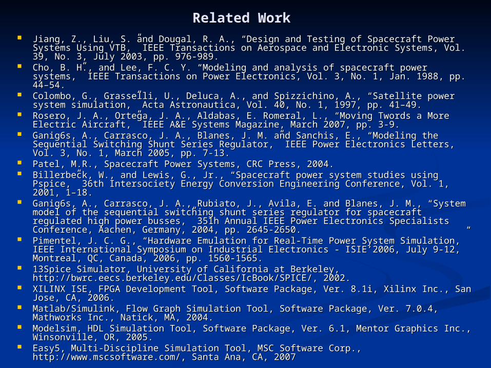
Related WorkRelated Work Jiang, Z., Liu, S. and Dougal, R. A., “Design and Testing of Spacecraft Power Systems Jiang, Z., Liu, S. and Dougal, R. A., “Design and Testing of Spacecraft Power Systems
Using VTB,” IEEE Transactions on Aerospace and Electronic Systems, Vol. 39, No. 3, Using VTB,” IEEE Transactions on Aerospace and Electronic Systems, Vol. 39, No. 3, July 2003, pp. 976-989.July 2003, pp. 976-989.
Cho, B. H., and Lee, F. C. Y. “Modeling and analysis of spacecraft power systems,” Cho, B. H., and Lee, F. C. Y. “Modeling and analysis of spacecraft power systems,” IEEE Transactions on Power Electronics, Vol. 3, No. 1, Jan. 1988, pp. 44–54.IEEE Transactions on Power Electronics, Vol. 3, No. 1, Jan. 1988, pp. 44–54.
Colombo, G., Grasselli, U., Deluca, A., and Spizzichino, A., “Satellite power system Colombo, G., Grasselli, U., Deluca, A., and Spizzichino, A., “Satellite power system simulation,” Acta Astronautica, Vol. 40, No. 1, 1997, pp. 41–49.simulation,” Acta Astronautica, Vol. 40, No. 1, 1997, pp. 41–49.
Rosero, J. A., Ortega, J. A., Aldabas, E. Romeral, L., “Moving Twords a More Electric Rosero, J. A., Ortega, J. A., Aldabas, E. Romeral, L., “Moving Twords a More Electric Aircraft,” IEEE A&E Systems Magazine, March 2007, pp. 3-9.Aircraft,” IEEE A&E Systems Magazine, March 2007, pp. 3-9.
Ganig6s, A., Carrasco, J. A., Blanes, J. M. and Sanchis, E., “Modeling the Sequential Ganig6s, A., Carrasco, J. A., Blanes, J. M. and Sanchis, E., “Modeling the Sequential Switching Shunt Series Regulator,” IEEE Power Electronics Letters, Vol. 3, No. 1, Switching Shunt Series Regulator,” IEEE Power Electronics Letters, Vol. 3, No. 1, March 2005, pp. 7-13.March 2005, pp. 7-13.
Patel, M.R., Spacecraft Power Systems, CRC Press, 2004.Patel, M.R., Spacecraft Power Systems, CRC Press, 2004. Billerbeck, W., and Lewis, G., Jr., “Spacecraft power system studies using Pspice,” Billerbeck, W., and Lewis, G., Jr., “Spacecraft power system studies using Pspice,”
36th Intersociety Energy Conversion Engineering Conference, Vol. 1, 2001, 1–18.36th Intersociety Energy Conversion Engineering Conference, Vol. 1, 2001, 1–18. Ganig6s, A., Carrasco, J. A., Rubiato, J., Avila, E. and Blanes, J. M., “System model of Ganig6s, A., Carrasco, J. A., Rubiato, J., Avila, E. and Blanes, J. M., “System model of
the sequential switching shunt series regulator for spacecraft regulated high power the sequential switching shunt series regulator for spacecraft regulated high power busses,” 351h Annual IEEE Power Electronics Specialists Conference, Aachen, busses,” 351h Annual IEEE Power Electronics Specialists Conference, Aachen, Germany, 2004, pp. 2645-2650.Germany, 2004, pp. 2645-2650.
Pimentel, J. C. G., “Hardware Emulation for Real-Time Power System Simulation,” Pimentel, J. C. G., “Hardware Emulation for Real-Time Power System Simulation,” IEEE International Symposium on Industrial Electronics - ISIE’2006, July 9-12, IEEE International Symposium on Industrial Electronics - ISIE’2006, July 9-12, Montreal, QC, Canada, 2006, pp. 1560-1565.Montreal, QC, Canada, 2006, pp. 1560-1565.
13Spice Simulator, University of California at Berkeley, 13Spice Simulator, University of California at Berkeley, http://bwrc.eecs.berkeley.edu/Classes/IcBook/SPICE/, 2002.http://bwrc.eecs.berkeley.edu/Classes/IcBook/SPICE/, 2002.
XILINX ISE, FPGA Development Tool, Software Package, Ver. 8.1i, Xilinx Inc., San XILINX ISE, FPGA Development Tool, Software Package, Ver. 8.1i, Xilinx Inc., San Jose, CA, 2006.Jose, CA, 2006.
Matlab/Simulink, Flow Graph Simulation Tool, Software Package, Ver. 7.0.4, Matlab/Simulink, Flow Graph Simulation Tool, Software Package, Ver. 7.0.4, Mathworks Inc., Natick, MA, 2004.Mathworks Inc., Natick, MA, 2004.
Modelsim, HDL Simulation Tool, Software Package, Ver. 6.1, Mentor Graphics Inc., Modelsim, HDL Simulation Tool, Software Package, Ver. 6.1, Mentor Graphics Inc., Winsonville, OR, 2005.Winsonville, OR, 2005.
Easy5, Multi-Discipline Simulation Tool, MSC Software Corp., Easy5, Multi-Discipline Simulation Tool, MSC Software Corp., http://www.mscsoftware.com/, Santa Ana, CA, 2007http://www.mscsoftware.com/, Santa Ana, CA, 2007

Critical Systems in a Lunar Critical Systems in a Lunar SettlementSettlement
Power System
Life Support (e.g. O2 and H2O processing and generation)
Transport system (e.g. evacuation modules)
Distributed Control Systems (e.g. supervisory control)

Validation and Validation and VerificationVerification
SimulationSimulation Off-lineOff-line Real-timeReal-time Hardware in the loopHardware in the loop
Formal methodsFormal methods Design by assertionDesign by assertion May be coupled to simulation based May be coupled to simulation based
methodsmethods

SimulationSimulation(Validate only what we know about)(Validate only what we know about)
System Model (Implementation)
Environmental Parameters
System Model
(high-level/ behavioral)
Low-level Simulator
High-level Simulator
Compare
Report of Bugs / Design Errors
Simulation => more computationally efficient

Formal MethodFormal Method(automatically validate the whole (automatically validate the whole
design space)design space)System Model
(Implementation)
Environmental Parameters
System Assertions
Model Checker
(Theorem Proofing)
Report of Bugs / Design Errors
Formal Methods => Much less efficient what limits the size of the design it can handle

State of the ArtState of the Art
Simulation:Simulation: Widely usedWidely used Not able to detect/cover all possible faultsNot able to detect/cover all possible faults Time consuming (write/run many simulation Time consuming (write/run many simulation
cases)cases) Formal Methods:Formal Methods:
Starting to be used for digital hardware Starting to be used for digital hardware designdesign
Not fully understood for hybrid systemsNot fully understood for hybrid systems Combinatory explosionCombinatory explosion

Mixed ApproachMixed Approach
System Model (Implementation)
Environmental Parameters
System Assertions
Model Checker
(Theorem Proofing)
Report of Bugs / Design Errors
Scenario co-simulation

Real-Time SimulationReal-Time SimulationHardware in the LoopHardware in the Loop
EquipmentUnderTest
DigitalRealTime
Simulator
(processing)(Z-1)
AnaAna
Ana
Dig
Dig
SamplingZ-1
Z-1
Sampling
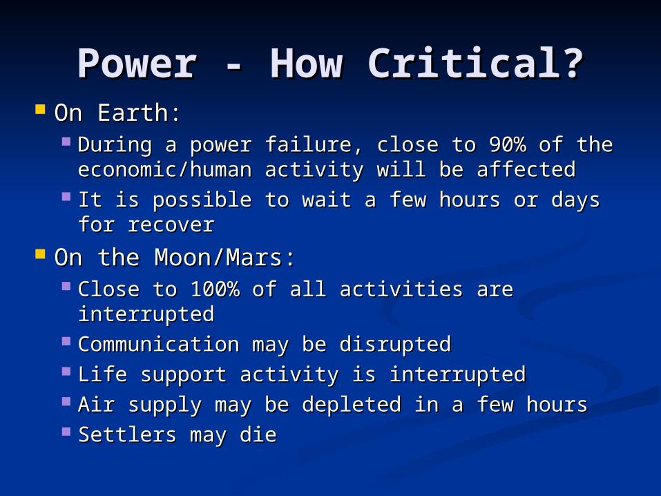
Power - How Critical?Power - How Critical? On Earth:On Earth:
During a power failure, close to 90% of the During a power failure, close to 90% of the economic/human activity will be affectedeconomic/human activity will be affected
It is possible to wait a few hours or days for It is possible to wait a few hours or days for recoverrecover
On the Moon/Mars:On the Moon/Mars: Close to 100% of all activities are interruptedClose to 100% of all activities are interrupted Communication may be disruptedCommunication may be disrupted Life support activity is interruptedLife support activity is interrupted Air supply may be depleted in a few hoursAir supply may be depleted in a few hours Settlers may dieSettlers may die
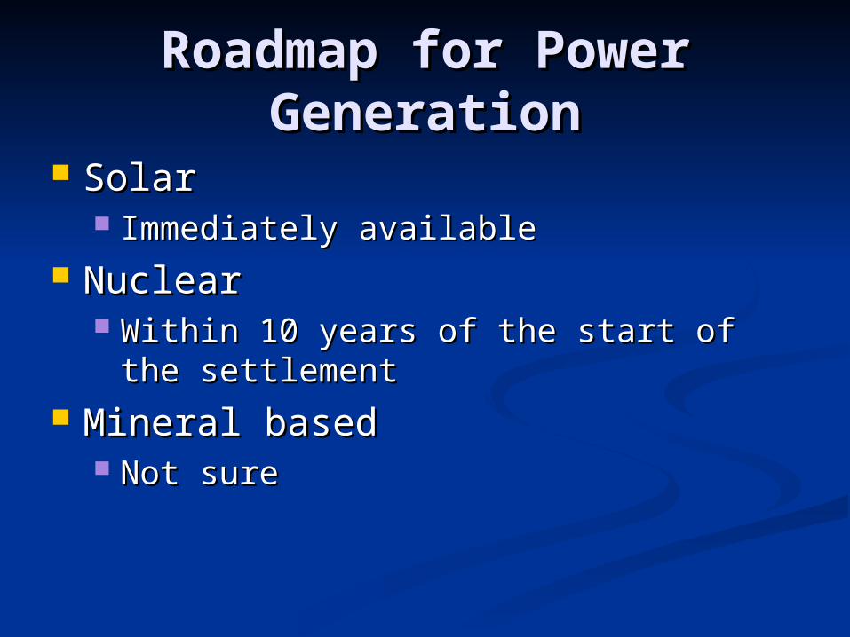
Roadmap for Power Roadmap for Power GenerationGeneration
SolarSolar Immediately availableImmediately available
NuclearNuclear Within 10 years of the start of the Within 10 years of the start of the
settlementsettlement Mineral basedMineral based
Not sureNot sure
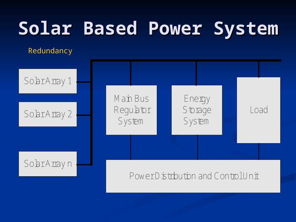
Solar Based Power Solar Based Power SystemSystem
Solar Array 1
Solar Array 2
Solar Array n
LoadEnergyStorageSystem
Main BusRegulatorSystem
Power Distribution and Control Unit
Redundancy
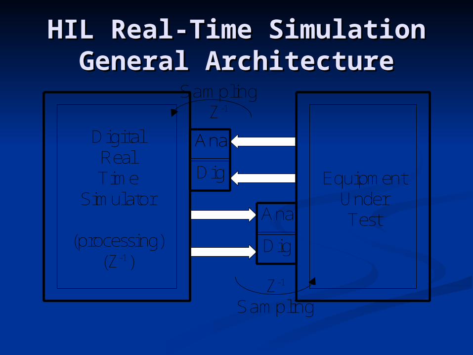
HIL Real-Time SimulationHIL Real-Time SimulationGeneral ArchitectureGeneral Architecture
EquipmentUnderTest
DigitalRealTime
Simulator
(processing)(Z-1)
AnaAna
Ana
Dig
Dig
SamplingZ-1
Z-1
Sampling

High Level ArchitectureHigh Level Architecture
Linearsub-circuit
Control
VoltageCurrent
VoltageCurrent
VoltageCurrent
VoltageCurrent
VoltageCurrent
VoltageCurrent
Scheduler
Non linear sub-circuits
State Space(Ad, Bd, Cd, Dd)
Control Control
Non linearSub-circuit
Non linearSub-circuit
Non linearSub-circuit
Non linearSub-circuit
Non linearSub-circuit
Non linearSub-circuit
Control
Examples of ModulesExamples of Modules
Voltages
EOC
LogicalSignals
Sub
CircuitCurrents
Voltages
Currents
LogicalSignals
RSTCLKS_CLKF_CLKENSTCREG
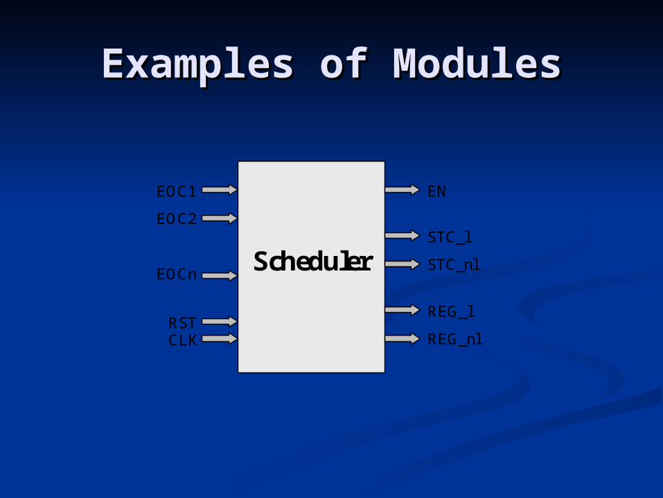
Examples of ModulesExamples of Modules
RSTCLK
EOC1
EOC2
EOCnScheduler
EN
STC_l
STC_nl
REG_l
REG_nl
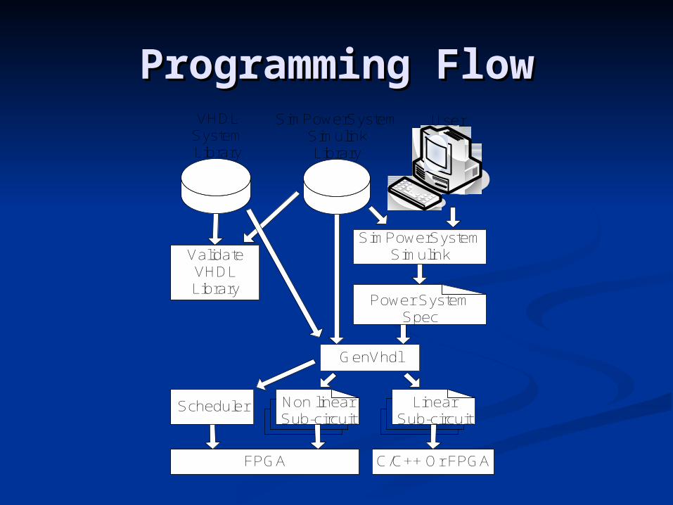
Programming FlowProgramming Flow SimPowerSystem
SimulinkLibrary
VHDLSystemLibrary
SimPowerSystemSimulink
GenVhdl
ValidateVHDLLibrary
User
Power SystemSpec
Non linearSub-circuit
LinearSub-circuit
C/C++ Or FPGAFPGA
Scheduler

Hardware Description Hardware Description LanguageLanguage
Component ModelingComponent Modelingentity DiscPIController isgeneric (NBits:natural:=8; NBitsRadix:natural:=8; NBitsCoef:natural:=8; PIType:natura :=0; NCycles:natural:=1; A1:natural:=1; A2:natural:=1; Init:natural:=0; UpperBound:integer:=1; LowerBound: integer:=0 ); port (CLK: in STD_LOGIC; RST: in STD_LOGIC; EN: in std_logic; STC: in std_logic; Reg_output: in std_logic; Verr: in std_logic_vector (NBits-1 downto 0); Vcont: out std_logic_vector (NBits-1 downto 0); EOC: out std_logic );
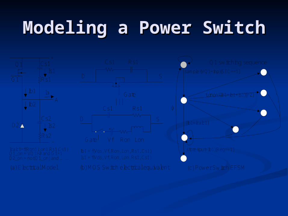
Modeling a Power SwitchModeling a Power Switch
ψ
sample!{VQ1=inp}[STC==1]
store!{out=Ib1}[Reg==1]
turnon!{Ib1=Ib1+Is1}[P2]
{Ib1=Icalc1}
Icalc1=f(Ron1,Lon1,Rs1,Cs1)
Rs1
Rs2
Cs1
Cs2D2
Q1
G1
+
-
A
Ib1
Ib2
Q1 switching sequence
Is1
Is2
Ia
Q1_on = VQ1>0 and G1=1D2_on = not(Q1_on) and …...
D S
Gate
D S
Gate
Cs1 Rs1
Cs1 Rs1
Ron Lon
Ib1 = f(Vds, Vf, Ron, Lon, Rs1, Cs1)
Vf
Is1 = f(Vds, Vf, Ron, Lon, Rs1, Cs1)
(a) Electrical Model (b) MOS Switch electrical equivalent (c) Power Switch EFSM Model

Mathematical ModelMathematical Model
( ) ( ) ( ) ( )ds f on ds on ds
dV t V t R I t L I t
dt
( ) (1/ )( )
( ) ( ) 1 ( / )ds on
ds f on on
I s RH s
V s V s s L R
1 2( ) ( ) ( 1))ds ds dsI n A V n A I n
sonon
on
sonon
s
TRL
LA
TRL
TA
21 ,
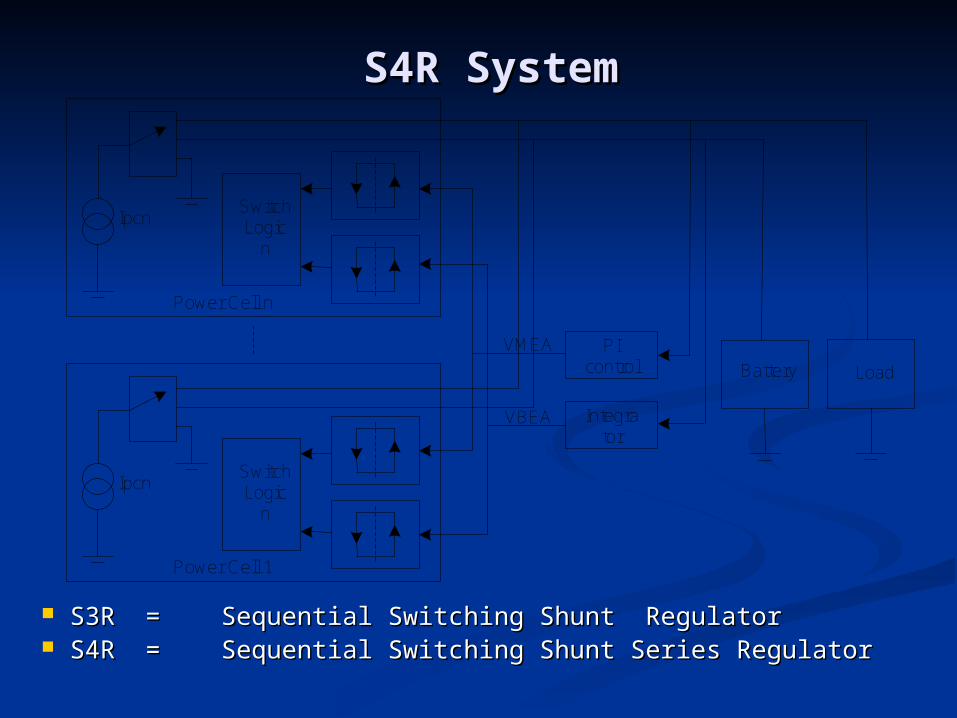
S4R SystemS4R System
SwitchLogic
n
Ipcn
Power Cell n
SwitchLogic
n
Ipcn
Power Cell 1
LoadBattery
PI control
Integrator
VMEA
VBEA
S3RS3R == Sequential Switching Shunt RegulatorSequential Switching Shunt Regulator S4RS4R == Sequential Switching Shunt Series RegulatorSequential Switching Shunt Series Regulator
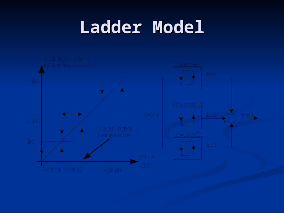
Ladder ModelLadder Model
Vcmp1 Vcmp2 Vcmpn
VMEA
VBEA
Main Bus CurrentBattery Bus Current Power cell n
Power cell 2
Power cell 1
++
+VMEA Itotal
Ipcn
Ipc2
Ipc1Ipc
2 Ipc
n Ipc
Bus or BatteryComparators
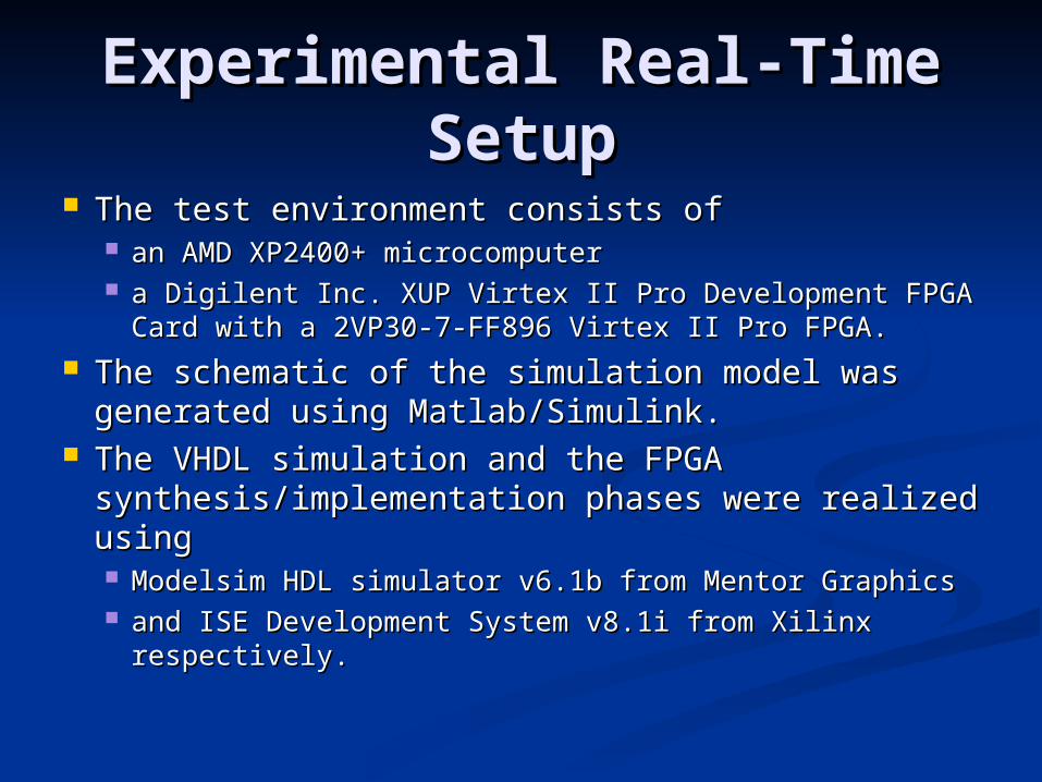
Experimental Real-Time Experimental Real-Time SetupSetup
The test environment consists of The test environment consists of an AMD XP2400+ microcomputer an AMD XP2400+ microcomputer a Digilent Inc. XUP Virtex II Pro Development FPGA a Digilent Inc. XUP Virtex II Pro Development FPGA
Card with a 2VP30-7-FF896 Virtex II Pro FPGA. Card with a 2VP30-7-FF896 Virtex II Pro FPGA. The schematic of the simulation model was The schematic of the simulation model was
generated using Matlab/Simulink. generated using Matlab/Simulink. The VHDL simulation and the FPGA The VHDL simulation and the FPGA
synthesis/implementation phases were realized synthesis/implementation phases were realized using using Modelsim HDL simulator v6.1b from Mentor Graphics Modelsim HDL simulator v6.1b from Mentor Graphics and ISE Development System v8.1i from Xilinx and ISE Development System v8.1i from Xilinx
respectively.respectively.
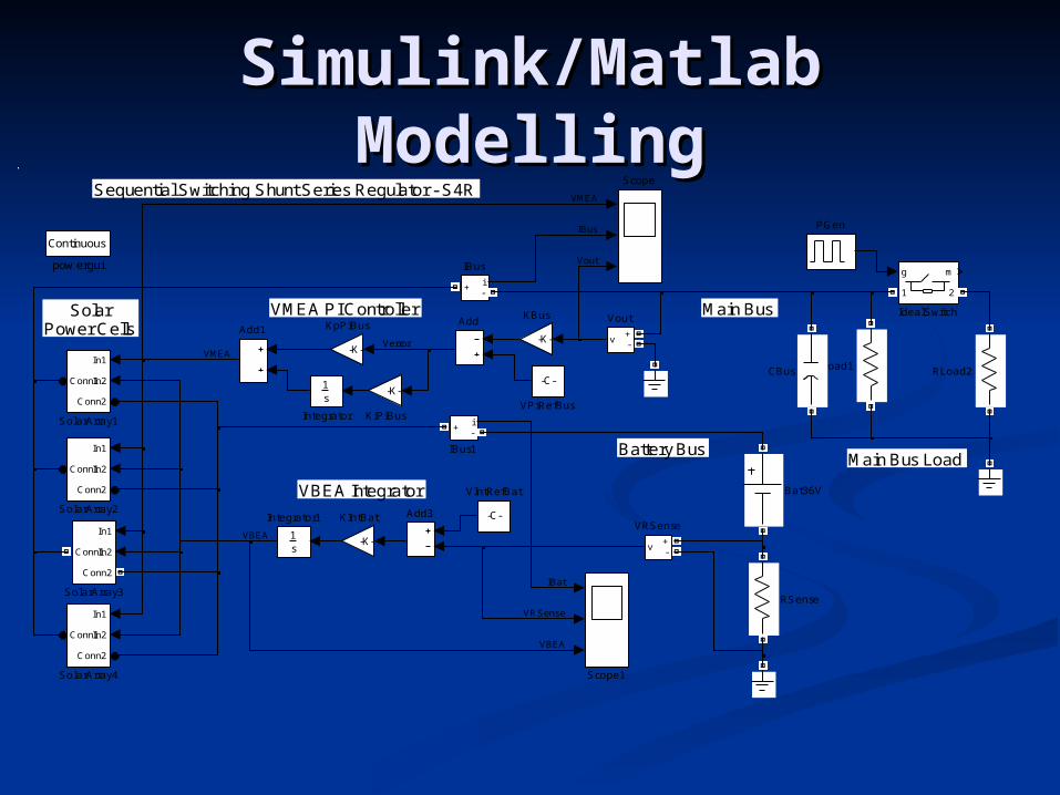
Simulink/Matlab Simulink/Matlab ModellingModelling
Main Bus
Battery BusMain Bus Load
SolarPower Cells
Sequential Switching Shunt Series Regulator - S4R
VBEA Integrator
VMEA PI Controller
Continuous
pow ergui
v+-
Vout
v+-
VRSense
-C-
VPiRefBus
-C-
VIntRefBat
In1
In2
Conn2
Conn1
SolarArray4
In1
In2
Conn2
Conn1
SolarArray3
In1
In2
Conn2
Conn1
SolarArray2
In1
In2
Conn2
Conn1
SolarArray1
Scope1
Scope
RSense
RLoad2RLoad1
PGen
-K-
KpPiBus
-K-
KiPiBus
-K-
KIntBat
-K-
KBus
1s
Integrator1
1s
Integrator
g m
1 2
IdealSwitch
i+ -
IBus1
i+
-
IBus
CBus
Bat36V
Add3
Add1Add
Vout
Verror
VMEA
VMEA
VRSense
VBEA
VBEA
IBat
IBus
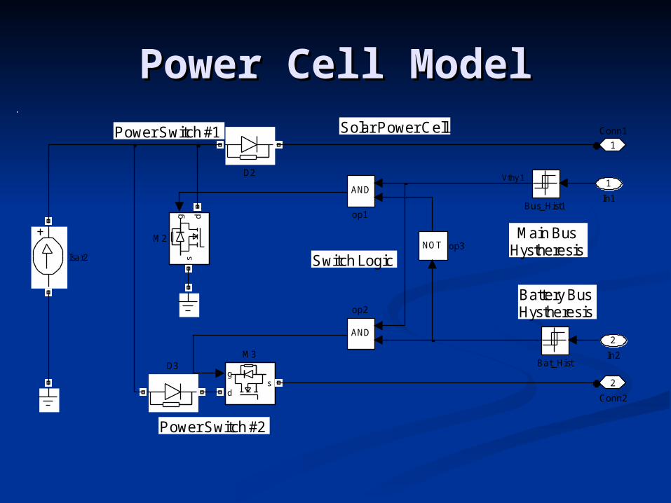
Power Cell ModelPower Cell ModelPower Switch #1
Power Switch #2
Solar Power Cell
Switch Logic
Main BusHystheresis
Battery BusHystheresis
2
Conn2
1
Conn1
NOT op3
AND
op2
AND
op1
g
ds
M3
g ds
M2
Isar2
D3
D2
Bus_Hist1
Bat_Hist
2
In2
1
In1
Vthy 1

S4R Main Bus Results S4R Main Bus Results (Matlab)(Matlab)
0 0.01 0.02 0.03 0.04 0.05
2
4
6
VM
EA
s4r1cell - Matlab/SymPowerSystems Simulation
0 0.01 0.02 0.03 0.04 0.050
2
4
IBu
s
0 0.01 0.02 0.03 0.04 0.0549.5
50
50.5
Vou
t
time(seconds)
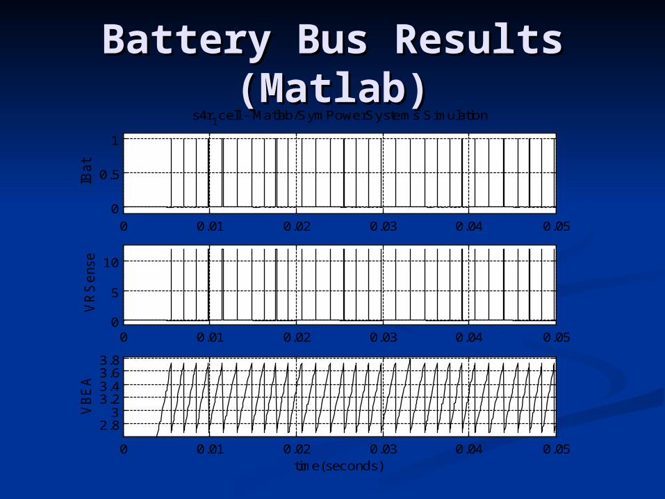
Battery Bus Results Battery Bus Results (Matlab)(Matlab)
0 0.01 0.02 0.03 0.04 0.050
0.5
1
IBa
t
s4r1cell - Matlab/SymPowerSystems Simulation
0 0.01 0.02 0.03 0.04 0.050
5
10
VR
Se
nse
0 0.01 0.02 0.03 0.04 0.05
2.83
3.23.43.63.8
VB
EA
time(seconds)

Bus Error (Matlab)Bus Error (Matlab)
0.021 0.0215 0.022 0.0225 0.023 0.0235 0.024
6
6.5
7
VM
EA
s4r1cell - Matlab/SymPowerSystems Simulation
0.0215 0.022 0.0225 0.023 0.0235 0.024
3
3.5
4
IBu
s
0.0215 0.022 0.0225 0.023 0.0235 0.024
49.9
50
50.1
Vou
t
time(seconds)
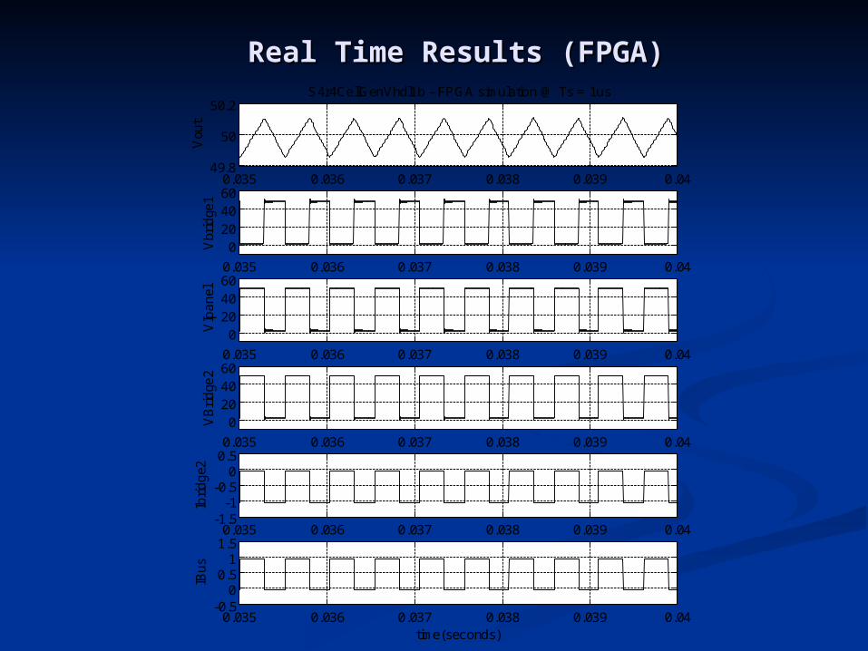
Real Time Results (FPGA)Real Time Results (FPGA)
0.035 0.036 0.037 0.038 0.039 0.0449.8
50
50.2
Vou
t
S4r4CellGenVhdl1b - FPGA simulation @ Ts = 1us
0.035 0.036 0.037 0.038 0.039 0.04
0204060
Vbr
idge
1
0.035 0.036 0.037 0.038 0.039 0.04
0204060
VIp
an
el
0.035 0.036 0.037 0.038 0.039 0.04
0204060
VB
rid
ge2
0.035 0.036 0.037 0.038 0.039 0.04-1.5
-1-0.5
00.5
Ibri
dg
e2
0.035 0.036 0.037 0.038 0.039 0.04-0.5
00.5
11.5
IBu
s
time(seconds)

Real Time Results (FPGA)Real Time Results (FPGA)
0.03 0.035 0.04 0.045 0.0549.5
50
50.5
Vou
t
S4r4CellGenVhdl4b - FPGA simulation @ Ts = 1us
0.03 0.035 0.04 0.045 0.050
5
IBus
time(seconds)

DiscussionDiscussion
The simulator uses low cost The simulator uses low cost reconfigurable computing infrastructure reconfigurable computing infrastructure (e.g. embedded processors and FPGAs).(e.g. embedded processors and FPGAs).
It is capable of having simulation steps It is capable of having simulation steps on the order of 0.4 microseconds.on the order of 0.4 microseconds.
It is suitable to represent typical It is suitable to represent typical modern aerospace power systems. modern aerospace power systems.
We realized the simulation of a We realized the simulation of a sequential switching shunt series sequential switching shunt series regulator (S4R) system regulator (S4R) system
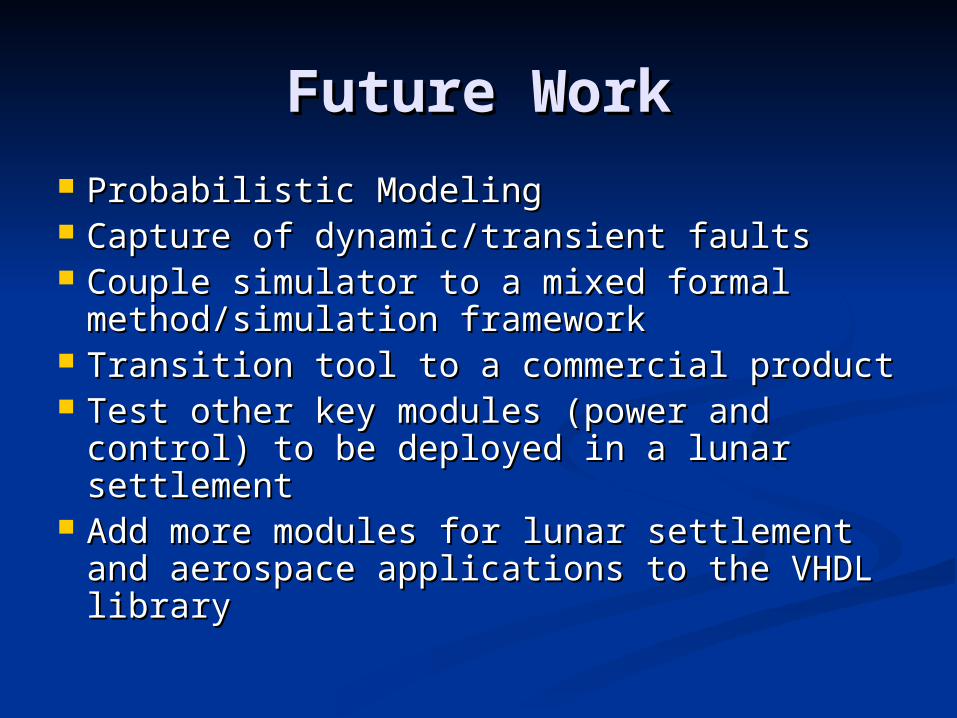
Future WorkFuture Work Probabilistic ModelingProbabilistic Modeling Capture of dynamic/transient faults Capture of dynamic/transient faults Couple simulator to a mixed formal Couple simulator to a mixed formal
method/simulation frameworkmethod/simulation framework Transition tool to a commercial productTransition tool to a commercial product Test other key modules (power and control) Test other key modules (power and control)
to be deployed in a lunar settlementto be deployed in a lunar settlement Add more modules for Add more modules for lunar settlementlunar settlement and and
aerospace applications to the VHDL library aerospace applications to the VHDL library