Embed Size (px)
Citation preview

Unclassified NEA/CSNI/R(2015)5 Organisation de Coopération et de Développement Économiques Organisation for Economic Co-operation and Development 01-Jun-2015
___________________________________________________________________________________________
_____________ English text only NUCLEAR ENERGY AGENCY
COMMITTEE ON THE SAFETY OF NUCLEAR INSTALLATIONS
Bonded or Unbonded Technologies for Nuclear Reactor Prestressed Concrete Containments
JT03377502
Complete document available on OLIS in its original format
This document and any map included herein are without prejudice to the status of or sovereignty over any territory, to the delimitation of
international frontiers and boundaries and to the name of any territory, city or area.
NE
A/C
SN
I/R(2
01
5)5
Un
classified
En
glish
text o
nly

NEA/CSNI/R(2015)5
2
ORGANISATION FOR ECONOMIC CO-OPERATION AND DEVELOPMENT
The OECD is a unique forum where the governments of 34 democracies work together to address the economic,
social and environmental challenges of globalisation. The OECD is also at the forefront of efforts to understand and to
help governments respond to new developments and concerns, such as corporate governance, the information economy
and the challenges of an ageing population. The Organisation provides a setting where governments can compare policy
experiences, seek answers to common problems, identify good practice and work to co-ordinate domestic and
international policies.
The OECD member countries are: Australia, Austria, Belgium, Canada, Chile, the Czech Republic, Denmark,
Estonia, Finland, France, Germany, Greece, Hungary, Iceland, Ireland, Israel, Italy, Japan, Luxembourg, Mexico, the
Netherlands, New Zealand, Norway, Poland, Portugal, the Republic of Korea, the Slovak Republic, Slovenia, Spain,
Sweden, Switzerland, Turkey, the United Kingdom and the United States. The European Commission takes part in the
work of the OECD.
OECD Publishing disseminates widely the results of the Organisation’s statistics gathering and research on
economic, social and environmental issues, as well as the conventions, guidelines and standards agreed by its members.
NUCLEAR ENERGY AGENCY
The OECD Nuclear Energy Agency (NEA) was established on 1 February 1958. Current NEA membership consists
of 31 countries: Australia, Austria, Belgium, Canada, the Czech Republic, Denmark, Finland, France, Germany, Greece,
Hungary, Iceland, Ireland, Italy, Japan, Luxembourg, Mexico, the Netherlands, Norway, Poland, Portugal, the Republic of
Korea, the Russian Federation, the Slovak Republic, Slovenia, Spain, Sweden, Switzerland, Turkey, the United Kingdom
and the United States. The European Commission also takes part in the work of the Agency.
The mission of the NEA is:
– to assist its member countries in maintaining and further developing, through international co-operation, the
scientific, technological and legal bases required for a safe, environmentally friendly and economical use of
nuclear energy for peaceful purposes;
– to provide authoritative assessments and to forge common understandings on key issues, as input to government
decisions on nuclear energy policy and to broader OECD policy analyses in areas such as energy and sustainable
development.
Specific areas of competence of the NEA include the safety and regulation of nuclear activities, radioactive waste
management, radiological protection, nuclear science, economic and technical analyses of the nuclear fuel cycle, nuclear
law and liability, and public information.
The NEA Data Bank provides nuclear data and computer program services for participating countries. In these and
related tasks, the NEA works in close collaboration with the International Atomic Energy Agency in Vienna, with which it
has a Co-operation Agreement, as well as with other international organisations in the nuclear field.
This document and any map included herein are without prejudice to the status of or sovereignty over any territory, to the delimitation of
international frontiers and boundaries and to the name of any territory, city or area.
Corrigenda to OECD publications may be found online at: www.oecd.org/publishing/corrigenda.
© OECD 2015
You can copy, download or print OECD content for your own use, and you can include excerpts from OECD publications, databases and multimedia products in your own documents, presentations, blogs, websites and teaching materials, provided that suitable acknowledgment of the OECD as source
and copyright owner is given. All requests for public or commercial use and translation rights should be submitted to [email protected]. Requests for
permission to photocopy portions of this material for public or commercial use shall be addressed directly to the Copyright Clearance Center (CCC) at
[email protected] or the Centre français d'exploitation du droit de copie (CFC) [email protected].

NEA/CSNI/R(2015)5
3
THE COMMITTEE ON THE SAFETY OF NUCLEAR INSTALLATIONS
The NEA Committee on the Safety of Nuclear Installations (CSNI) is an international committee
made up of senior scientists and engineers with broad responsibilities for safety technology and
research programmes, as well as representatives from regulatory authorities. It was created in 1973 to
develop and co-ordinate the activities of the NEA concerning the technical aspects of the design,
construction and operation of nuclear installations insofar as they affect the safety of such
installations.
The committee’s purpose is to foster international co-operation in nuclear safety among NEA
member countries. The main tasks of the CSNI are to exchange technical information and to promote
collaboration between research, development, engineering and regulatory organisations; to review
operating experience and the state of knowledge on selected topics of nuclear safety technology and
safety assessment; to initiate and conduct programmes to overcome discrepancies, develop
improvements and reach consensus on technical issues; and to promote the co-ordination of work that
serves to maintain competence in nuclear safety matters, including the establishment of joint
undertakings.
The priority of the committee is on the safety of nuclear installations and the design and
construction of new reactors and installations. For advanced reactor designs, the committee provides a
forum for improving safety-related knowledge and a vehicle for joint research.
In implementing its programme, the CSNI establishes co-operative mechanisms with the NEA
Committee on Nuclear Regulatory Activities (CNRA), which is responsible for issues concerning the
regulation, licensing and inspection of nuclear installations with regard to safety. It also co-operates
with other NEA Standing Technical Committees, as well as with key international organisations such
as the International Atomic Energy Agency (IAEA), on matters of common interest.

NEA/CSNI/R(2015)5
4

NEA/CSNI/R(2015)5
5
TABLE OF CONTENTS
FOREWORDS ................................................................................................................................................ 7
LIST OF CONTRIBUTORS ........................................................................................................................... 8
LIST OF ABBREVIATIONS ......................................................................................................................... 9
VOCABULARY ........................................................................................................................................... 11
EXECUTIVE SUMMARY ........................................................................................................................... 13
1. CONTEXT AND OBJECTIVE ............................................................................................................. 15
1.1 Context ............................................................................................................................................ 15
1.2 Objective ......................................................................................................................................... 16
2. SAFETY OBJECTIVES OF THE CONCRETE PRESTRESSED CONTAINMENT ......................... 17
2.1 Safety objectives ............................................................................................................................. 17
2.2 General provisions for the containment prestressing from a safety point of view (for each
phases of the project) ................................................................................................................................. 18
3. OVERVIEW OF DIFFERENT PRESTRESSING TECHNOLOGIES COMPONENTS ..................... 21
3.1 General ............................................................................................................................................ 21
3.2 Prestressing reinforcements example (EPR) ................................................................................... 23
3.3 Overview of different prestressing technologies for nuclear containments VVER 1000 V-320
type containment ........................................................................................................................................ 24
3.4 Greased sheathed strands (GSS) technology .................................................................................. 27
4. GENERAL PHILOSOPHY OF BONDED AND UNBONDED, AIRCRAFT ASPECTS AND
TECHNICAL CONSIDERATIONS ............................................................................................................. 31
4.1 General philosophy ......................................................................................................................... 31
4.2 Aircraft impact aspects ................................................................................................................... 32
4.3 Technical considerations for both technologies .............................................................................. 34
5. FEEDBACK EXPERIENCE OF THE PERFORMANCE OF PRESTRESSING TENDONS ............. 37
5.1 Introduction ..................................................................................................................................... 37
5.2 Non-nuclear domain ........................................................................................................................ 37
5.3 Nuclear domain ............................................................................................................................... 45
5.4 Conclusions from non-nuclear and nuclear feedback ..................................................................... 58
6. DESIGN ................................................................................................................................................. 59
6.1 Introduction ..................................................................................................................................... 59
6.2 Design Basis Level ......................................................................................................................... 59
6.3 Beyond design ................................................................................................................................. 79
7. CONSTRUCTION ............................................................................................................................... 109
7.1 General principles ......................................................................................................................... 109
7.2 Requirements for containment structure ....................................................................................... 109
7.3 Material handling, traceability and tests ....................................................................................... 115
7.4 Manufacturing of tendons ............................................................................................................. 120
7.5 Installation..................................................................................................................................... 121

NEA/CSNI/R(2015)5
6
7.6 Tensioning..................................................................................................................................... 123
7.7 Injection of tendons by cement grout ............................................................................................ 125
7.8 Injection of tendons by grease ...................................................................................................... 128
7.9 Installation of tendon instrumentation .......................................................................................... 129
7.10 Anchor protection .................................................................................................................... 129
7.11 Summary report ....................................................................................................................... 130
7.12 Full-scale mock-up for qualification – an example for EPR ................................................... 130
8. IN-SERVICE INSPECTION FOR CONTAINMENTS ...................................................................... 143
8.1 Unbonded tendons ........................................................................................................................ 143
8.2 Bonded tendons ............................................................................................................................. 157
8.3 GSS technology ............................................................................................................................ 201
9. IN-SERVICE INSPECTION: CZECH EXPERIENCE ....................................................................... 208
9.1 Check of cables prestressing ......................................................................................................... 208
9.2 Check of cables condition ............................................................................................................. 209
9.3 Tests of strain-gauge measuring systems ...................................................................................... 213
9.4 Tests of the cables taken out ......................................................................................................... 214
9.5 Tests of drag anchors and eye rings .............................................................................................. 217
9.6 Qualification of measuring systems (sensors of force) ................................................................. 219
10. SUMMARY AND RECOMMENDATIONS .................................................................................. 221
11. REFERENCES ................................................................................................................................. 223

NEA/CSNI/R(2015)5
7
FOREWORDS
This report has been written in the framework of the Working Group on Integrity and Ageing of
Components and Structures (IAGE WG) of NEA, and more precisely with an active participation of
members of the Concrete sub-group. This activity is fully consistent with the OECD/NEA-medium-
term strategies for IAGE concrete working group (2006) and specifically with the proposed priorities
(High priorities: Containment & Tightness and Prestressing Losses). This report is the result of three
workshops:
The Lyon April 20th and 21th 2011 workshop dedicated to technical presentation in order the
share technical experience and feedback, and to agree the organization of the document and
main work load distribution
The Lyon November 26th and 27th 2011 workshop dedicated to the detailed definition of the
document content and additional technical presentations focused on critical issues.
The Helsinki December 9th and 10
th 2013 workshop dedicated to the detailed review of an
official draft given to everybody before the meeting
But this activity has to be considered not only on the basis of this report but also as an actual
international platform for technician exchanges. These exchanges have been particularly intense not
only during meeting, but also between meeting, and we hope also after.
OECD/NEA thanks every contributors whose list is just here after and specifically the two
inseparable and complementary pilots of this CAPS activity who was Etienne Gallitre and Pentti
Varpasuo.

NEA/CSNI/R(2015)5
8
LIST OF CONTRIBUTORS
Abrishami, Homayoun Candu Energy Inc., Canada
Barré, Francis Geodynamique et Structures, France
Borgerhoff, Michael Stangenberg und Partner Ingenieur-GmbH, Germany
Bumann, Urs ENSI, Switzerland
Calonius, Kim VTT Technical Research Centre of Finland
Courtois, Alexis EDF, France
Debattista, Jean-Marc EDF, France
Elison, Oscar Scanscot Technology, Sweden
Gallitre, Etienne EDF, France
Graves, Herman U.S. NRC, USA
Huerta, Alejandro OECD Nuclear Energy Agency (NEA)
Isard, Cedric EDF, France
Jackson, Paul Ramboll, UK
Kjellin, Daniel SSM, Sweden
Lillhök, Sofia SSM, Sweden
Louhivirta, Jari STUK, Finland
Martin, José CSN, Spain
Myllymäki, Jukka STUK, Finland
Nakano, Makio JNES, Japan
Puttonen, Jari Aalto University, Finland
Rambach, Jean-Mathieu IRSN, France
Sircar, Madhumita U.S. NRC, USA
Smith, Leslie Office for Nuclear Regulation, UK
Stepan, Jan UJV, Czech Republic
Tarallo, François IRSN, France
Tcherner, Julia Candu Energy Inc., Canada
Touret, Jean-Pierre Scanscot Technology, France
Varpasuo, Pentti Fortum, Finland
Välikangas, Pekka STUK, Finland
White, Andrew OECD Nuclear Energy Agency (NEA)

NEA/CSNI/R(2015)5
9
LIST OF ABBREVIATIONS
ACI: American Concrete Institute
AFCEN: French Association for Nuclear Reactor Codification
ASME: American Society of Mechanical Engineers
CCB: Concrete Containment Building
CEN: European Committee for Standards
CSA: Canadian Standards Association
COFRAC: Le Comité français d’accréditation
EN: European standards maintained by CEN (European Committee for Standardization)
EPR: European Pressurized Reactor
ETA: European Technical Approval
ETAG: European Technology Assessment Group
ETC-C: EPR Technical Code for Civil works
FIB: International Organization for Concrete
FE: Finite Element
FEM: Finite Element Method
GSS: Greased Sheathed Strands
HPDE: High Density Polyethylene
ILRT: Integrated Leak Rate Test
ISIT: Initial Structural Integrity Test
JSME: The Japan Society of Mechanical Engineers
LOCA: Loss of Cooling Accident
LCPC: (French) National Laboratory for Bridges and Roads (today: IFSTTAR)
LVDT: Linear Variable-Differential Transformer
LRT: Leak Rate Test
NPP: Nuclear Power Plant
OCN: Oconee Nuclear station
OSS: Optimal Surveillance System (French practice)
PCC: Prestressed Concrete Containment
PP: Polypropylene
PPT: Preoperational Proof Test
PE: Polyethylene
PVC: Polyvinylchloride
RC: Reinforced concrete
RG: (US) Regulatory Guide
SCOSS: (UK) Standing Committee on Structural Safety

NEA/CSNI/R(2015)5
10
SETRA: (French) State Division for Transportation Studies
SIA: Swiss Society of Engineers and Architects
SL-2: Seismic Level 2 (usually design earthquake)
THTR: Thorium High Temperature Reactor
USNRC: Nuclear Regulatory Commission for the United States of America
VIPP: Bridge with simply supported spans using prestressed beams
VWSG: Vibrating Wire Strain Gauge
NEA/CSNI/R(2015)5
11
VOCABULARY
Anchor head: End of tendon where prestressed forces are transferred to the concrete
through a dedicated metallic device
Bonded: With mechanical connection
Containment: Structure surrounding the reactor which prevents the release of radioactive
products and can withstand to pressure in case of accident
Creep: Property of material which volume decreases when submitted to load
Duct: Pipe put in place in the formwork which contain the tendons
Design Basis Domain: Set of load cases covered by national codes
Design Extension Domain: Set of load cases not covered by national codes, but which have to be
taken into account for design or for safety assessment
Discretization: Modelling technique consisting on dividing structure element into small
parts called finite elements
Eurocode: European Standard for Civil Works Design
Grease: Organic semi-liquid material dedicated to tendon anti-corrosion protection
Grout: Product made of cement and water which protects the tendons from
corrosion
Lift-off: Short uplift of prestressed tendon end in order to measure the effective
tension
Relaxation: Diminution of stress with time
Sheathed: Located inside a protection sheath
Shrinkage: Property of material which volume decreases with time
Strand: Set of wires for prestressing system (a set of strands is a tendon)
Tendon: Set of strands or set of wires if these wires are not gathered in strands
Unbonded: Without mechanical connection
Wax: Solid greased dedicated to tendon anti-corrosion protection
Wire: Unique filament of metal

NEA/CSNI/R(2015)5
12

NEA/CSNI/R(2015)5
13
EXECUTIVE SUMMARY
OECD/NEA/CSNI Working Group on Integrity and Ageing of Components and Structures
(WGIAGE) has the main mission to advance the current understanding of those aspects relevant to
ensuring the integrity of structures, systems and components under design and beyond design loads, to
provide guidance in choosing the optimal ways of dealing with challenges to the integrity of operating
as well as new nuclear power plants, and to make use of an integrated approach to design, safety and
plant life management. The work related to the risks of the loss of pre-stressing force in concrete
structures has been in high priority during the activities of the concrete sub-group of WGIAGE.
Therefore, the CAPS of WGIAGE: Study on post-tensioning methodologies in containments, was
approved by CSNI in June 2009.
In this study the two post-tensioning methodologies: bonded and unbonded methods and their
technological features are analysed. In the bonded technology, the tendon cannot slide in its duct due
to the cement grouting which is injected after tensioning. In the unbonded technology, the tendon can
slide inside its duct, the corrosion protection is given by grease, wax or dry air. A key point
concerning the assessment of durability and safety of prestressed concrete containments is the
technology chosen for tendon protection: bonded with cement grout or unbonded and protected by
grease or soft products. The mechanical behaviour of the containment is directly influenced by the
adherence of the tendons to the concrete, locally and under high stresses in case of severe accident.
The bonded or unbonded tendons of post-tensioned concrete containment of the Nuclear Power Plants
have the major role of containment (balance of the pressure effect during design basis and beyond
design accident). Many difficulties around the design, the construction and the in service inspection
are related to the tendons.
The main goal of the CAPS work was to clarify the consequences and necessary procedures when
choosing the post-tensioning technologies in terms of design basis, in terms of behaviour during
severe accident, in term of construction requirements as well as in term of monitoring and in-service
inspection of the containment. The choice of the post-tensioning technology is related to the life time
extension procedures of old plants as wells as to the construction methods of new NPP’s. Today, the
performance of the containment in severe accident conditions is a part of the design safety assessment
and this report presents how the different technologies impact these methods.
The work was done by collecting the information on methods and different methodologies
including their application and operating experiences in the existing plants and ongoing projects in
member countries during three workshops in years 2011-2013. The document has three parts: design,
construction and in service inspection in order to cover all aspects, from the beginning to the end:
every part will be summarised in the full paper. This work led to a very productive exchange platform,
where the main experts of this subject have contributed with their experiences regarding these
problems and methods used to solve them.
The results of the work are summarised in chapter 10. The most important results are as follows:
For new structures, data collection should start during construction (at least at the beginning
of the tensioning of the cables) so that the initial state, i.e. baseline parameters could be
established at the end of the construction period.

NEA/CSNI/R(2015)5
14
Differences of the unbonded and for bonded tendons to the maintenance aspects are taken
into account in the early design of new construction to be sure that all aspects to the
accessibility, inspections and preventive maintenance are managed in a relevant way.
Procedures of monitoring and In-Service Inspection methods of containment should
carefully be defined and approved with special features of chosen technology for the new
and existing plants to make sure that all safety goals are fulfilled
Direct monitoring of the bonded post-tensioning system is currently not possible, proven
reliable indirect methods should be used for the new and existing plants to ensure continuous
integrity of the post-tensioning system over the service life of the plant.
One important recommendation of this study is that the correct modelling of the tendon bonding
condition with concrete around the tendons is important, especially when the Design Extension
Conditions are taken into account in the design of new constructions. For the new and existing plants
the lifetime monitoring, maintenance and testing procedures must be designed and reviewed according
to the choice of the protective system for tendons, namely, bonded or unbonded protective system.

NEA/CSNI/R(2015)5
15
1. CONTEXT AND OBJECTIVE
1.1 Context
This OECD activity has been launched in the frame of a NEA/CSNI CAPS as it is usually done for
such a technical topic. The context is related to two main challenges for nuclear engineering, life time
extension of existing plants and construction of new ones. The post tensioning methodology has to be
carefully addressed in both situations due to the high importance of the tendons for the containment
capacity. To perform this analyse two aspects have to be tacked: The performance of the containment in
severe accident conditions is today a part of the plant safety re-assessment: such re-assessment needs
numerical simulation. The way to represent the tendons and their link to the concrete may have an impact
on the results. This question concerns both new and existing plants
For existing plants the questions are mainly related to In-Service Inspection and Monitoring
which obviously depend on the technology. Monitoring has to be linked to parameter values
intended for safety assessment and ISI scoping has to be consistent with variability of the
materials and the ageing effects.
These two issues are not so easily solved, and an international cooperation is necessary in order to
share good and bad experiences.
1.1.1Definitions
Unbonded technology: in this technology, the tendon can slide inside its duct, the corrosion
protection is given by grease, wax or dry air (GSS belong to that family)
Figure 0.1 Unbonded tendons
Bonded technology: in this technology, the tendon cannot slide in its duct due to the cement
grouting which is injected after tensioning.

NEA/CSNI/R(2015)5
16
Figure 0.2 Bonded tendons (grouted with cementitious grout)
A key point concerning the assessment of durability and safety of prestressed concrete containments
is the technology chosen for tendon protection: bonded with cement grout or unbonded and protected by
grease or soft products. The mechanical behaviour of the containment is directly influenced by the
adherence of the tendons to the concrete, locally and under high stresses in case of severe accident.
1.2 Objective
One objective is to clearly identify the technical considerations of both technologies (bonded versus
unbonded), not in order to rank one before the other, which would be useless due to the reliability of both,
but in order to properly address the drawbacks.
In this document, we will use the term bonded instead of grouted to emphasize on mechanical contact
between tendons and concrete by bond. Instead of “greased”, we will use the term “unbonded” which
emphasizes the inspectability of the tendons during the lifetime of the plant.
To do this it is necessary to understand the mechanisms that affect the materials, our ability to catch
them in reality, our ability to represent the behaviour of structure, in order to summarize our ability to
predict the containment performance under accidental conditions, taking into account ageing effects.
Every participant in this OECD activity has actual experience of areas of these issues but needs more
information and more cross check validation due to the complexity of the situation.
The main objective of this CAPS is, obviously, to produce a guideline to help every country in the
choice of technology but mainly to clarify the consequences of their choice in terms of design basis, in
terms of behaviour during severe accident, in term of construction requirements, in term of monitoring and
in-service inspection of the containment.

NEA/CSNI/R(2015)5
17
2. SAFETY OBJECTIVES OF THE CONCRETE PRESTRESSED CONTAINMENT
2.1 Safety objectives
The containment is the final barrier to protect the environment and public against uncontrolled release
of radionuclides, so the PCC has to fulfil the following requirements:
Confinement (tightness): improving the leak tightness of the wall (in the absence of steel liner or
complementary coating),
Resistance against pressure loads by limiting its membrane tension forces and flexural moments
when submitted to inner pressure (by pressure test or internal LOCA or Severe accident),
Limitation of concrete cracking in all situations, namely along the inner face (in contact with the
steel liner or without liner) improving the reversibility of the mechanical behaviour (elastic
behaviour) of the wall,
Protection against internal and external hazards,
Stability of the containment wall, during the lifetime of the installation.
2.1.1 Defence in depth
In addition to the design provisions, the prestressing shall exhibit sufficient ruggedness/robustness, in
order to avoid any cliff-edge effect, when considering any variation of parameters of interest on the actions
side (pressure, temperature, concrete creep and shrinkage) and on the resistance side (yield limits, ultimate
deformation, losses due to tendon/sheath friction, steel relaxation, anchorage draw-in, tensioning force). In
particular, the tendons are generally the last component of the containment that remain in its elastic domain
when the inner pressure level increases and they can be considered as the ultimate structural reinforcement
responsible for the leak tightness (by limitation of the steel liner deformations) and later of the overall
stability. So the following defence in depth principles have to be considered.
2.1.1.1 Proven engineering design
Robustness in conception and design itself shall be found by using proven engineering design, for
instance by using hand calculation for the spacing of the tendons in parts of the containment wall. The FE
models are used for checking the stress state in concrete and for the general overview of the losses of
prestressing during the construction phases and at the end of lifetime of the installation.
2.1.1.2 Design extension and margins
The bonded tendons adhere to their ducts and therefore to the rest of the structure; the unbonded
tendons are not continuosly fixed onto the surrounding structure and, in case of overtension, they tend to
slip along the duct when the imposed deformation by the wall is not homogeneous: this situation is difficult
to simulate by calculation and may initiate wire/strand/tendon rupture. In case of wire rupture, the missing
force is added to the adjacent wires that may in turn induce successive wire ruptures, up to strand failure
then up to the tendon failure itself: a local rupture of any bonded tendon induces the loss of all the

NEA/CSNI/R(2015)5
18
prestressing from the tendon. The margins in prestressing are to be found in the tensioning level (the lower
the tensioning force, the higher the margin) and in the losses of prestressing in the tendon (due to anchor
draw-in, friction coefficient, deferred permanent deformation). New concepts for tendons (like sheathed
greased strands) exhibit a better use of the prestressing steel, with less losses of prestressing (namely by
reducing the friction coefficients), but, conversely, they exhibit less margins regarding beyond design
considerations.
2.2 General provisions for the containment prestressing from a safety point of view (for each phases
of the project)
2.2.1 General provisions
Design the prestressing force distribution shall counteract, for the best, the external applied forces by
adapting the tendon locations (through their position in the section and their spacing inside the grid) and a
modified level of tensioning force; the design shall comply with a design code for prestressing that
complies with the approved reference described in the Safety Report.
2.2.2 Modification of containment
Bonded tendons do not allow any major modification of the containment (like widening the
equipment hatch or creating a new penetration), as opposed to the unbonded tendons that may be (partially)
detensioned, replaced (if necessary) and retensioned. However, for this type of tendon, great attention has
to be paid to the detensioning and retensioning, in terms of quantity of tendons and of operations phasing,
in order to limit any detrimental effects on the structure.
2.2.3 Construction
Competence: the civil Contractor in charge of the implementation of the prestressing shall be
competent in this highly specialized domain; it is recalled that the prestressing is a system (not only a
collection of items and a succession of acts), generally patented, for which the final responsibility cannot
be simply shared.
Procurement: the procurement and storage conditions shall comply with the standard of the
provider(s) for all necessary items involved in the prestressing, these standards being mentioned in an
approved reference that shall be described in the Safety Report.
Erection: all the activities dealing with the prestressing erection before tensioning shall comply with
the standards of the Contractor in charge, these standards being mentioned in an approved reference that
shall be described in the Safety Report; special attention must be paid to the location of the ducts within the
formwork according to tolerances defined by the Designer.
Tensioning: all the activities dealing with the tensioning shall comply with the standards of the
Contractor in charge, these standards being mentioned in an approved reference that shall be described in
the Safety Report; the tensioning sequences have to be defined by the Designer in order to minimize
potential harmful effects and any field modifications shall be approved by the Designer; the mechanical
parameters responsible of the losses of prestressing are to be checked in situ and interpreted by the
Designer, before the tensioning; the effectiveness of the tendon forces shall be confirmed by monitoring
during the tensioning; the tendon extension has to be recorded by the Contractor, transmitted to the
Designer and compared to its theoretical value.
Protection: the materials for protection (cementitious grout mix, wax or grease) and the procedure for
injection shall be defined, approved and tested on site by mock-ups.

NEA/CSNI/R(2015)5
19
2.2.4 Operating
Monitoring: the maintenance of the tension in the tendon and/or of the compression in concrete wall
shall be checked by adequate monitoring and recording throughout the life of the containment and during
periodic tests (mechanical and air leakage); the results should be reported to the responsible parties and
analysed properly Maintenance: all visible parts of the containment shall be periodically inspected, and if
necessary repaired; failed monitoring sensors shall be replaced.
2.2.5 Decommissioning
Decommissioning and dismantling: dismantling shall be forecast, at conception and at design stage, in
order to minimize the risks for the operators during tendon detensioning.

NEA/CSNI/R(2015)5
20

NEA/CSNI/R(2015)5
21
3. OVERVIEW OF DIFFERENT PRESTRESSING TECHNOLOGIES COMPONENTS
3.1 General
The safety of all nuclear facilities depends on the integrity of civil structures, among them the
prestressed concrete pressure vessel of advanced gas cooled reactors and the PCC of PWRs are key
structures. The containment building is a large volume reinforced concrete structure, which houses the
reactor, reactor cooling or recirculation system, pressurizer and pumps.
The PCC is highly reliable under maximum design conditions and accident loads and actions from
outside. A typical PCC is a large vertical cylinder closed at the bottom with a flat slab and at the top with a
convex hemi-spherical or sloping ellipsoid dome.
The high in-service reliability of the PCC is determined primarily by the fact that operating as well as
the emergency loads are supported by the post-tensioning system.
This system consists of a large number of prestressed tendons made of high-strength wire, strand or
bar. The tendons are inserted in tendon sheaths, which form ducts through the concrete shell between
anchorage points. The duct through which the tendon passes can be filled with a corrosion inhibiting
grease. Tendons are tensioned and then anchored to the hardened concrete forming the PCC.
Tendons operate independently with multiple overlapping of the action zones of each. An unlikely
failure of one or several tendons does not result in any appreciable changes in the stress and strain state of
the PCC and it is able to sustain high internal pressures (in incidents) and protects the reactor against
extreme climatic and external effects in-service.
Three major categories of prestressing reinforcement exist depending on the type of tendon utilized: wire,
bar or strand tendons. The different schemes of tendons layout in PCC adopted in various countries are
presented in

NEA/CSNI/R(2015)5
22
Figure 0.1 below.

NEA/CSNI/R(2015)5
23
Figure 0.1 Different schemes of tendon layout
3.2 Prestressing reinforcements example (EPR)
The prestressing tendons are made of high-strength wire. In the European PWR project, they are
composed of steel class 1860 MPa strands which comply with the following requirements:
The nominal diameter of strands shall be 15.7 mm. Each strand are composed of 7 wires and
have a nominal cross section area of 150 mm².
Tendons are composed of a maximum of 55 strands. The number of strands per tendon and the
number of tendons is defined by the detailed designer specifications.
Other class of strands (higher class only) may be used, but are to be justified in accordance with the
design and the whole objective of prestressing.
Strands are certified, according to the regulation, by the Approved Body (or Notified Body) as defined
by ETAG 013. The following requirements are included in the certification rules:
Strands are constituted of special non-alloy special steels according to EN 10020
Standard Pr EN 10138 applies, modified by the following requirements:
- The diameter of the central wires of the strands are at least 1.02 times greater than the
diameter of the outer peripheral wires of the strands,
- The relaxation of the strands are evaluated with loads equal to 0.7 Fm,a and 0.8 Fm,a and
the results are respectively lower than or equal to 2.5% and 4.5% at 1000 h. The relaxation
test are performed over at least 240 h, and results may be extrapolated to 1000 h,
- Corrosion strength under stress is evaluated with solution A (as defined in EN 15630-3).
Durations are greater or equal to 1.5 h and the average duration are greater or equal to 4 h.
3.2.1 Anchorage components
All anchorage components comply with the ETA of post-tensioning system (including the permanent
or temporary anchorage caps).
The bearing device consists of a cast-iron plate with a non-separate guide. The guide shall possess two
load transfer flanges.

NEA/CSNI/R(2015)5
24
3.2.2 Ducts
Ducts can be either of the 2 following types:
Rigid hand-bendable steel strip sheaths: used for non-deviating horizontal tendons (hoops with
radius of curvature ≥ 80 times the inner diameter of the sheath),
Machine-bendable steel tubes: used for all other ducts or parts of ducts.
3.2.3 Steel tubes
Tubes are round steel section, fabricated from hot-rolled products and longitudinally welded. Welds
have to be smoothed. The tubes have to be capable of withstanding the following shaping operations:
Cold forming at ends so as the minimum internal diameter at bell-mouth ends is equal to the
external diameter of the tube in a continuous section plus a value justified in the dedicated
procedure of the post-tensioning specialist company;
Bending by machine with a regular minimum radius. If the section becomes ovalised, the
minimum internal diameter has to be greater than the specified minimum value given in the
dedicated procedure of the post-tensioning specialist company.
3.2.4 Steel strip sheaths
Steel strip sheaths are fabricated from rolled steel strips. Sheaths are, in general, phosphated and
soaped: the friction coefficient is checked by tests.
3.2.5 Heat-shrinkable sleeves
Heat-shrinkable sleeves can be made with reticulated modified polyolefin, with a heat-fusible internal
coating and dimensions such that the external nominal diameter of the duct and the sleeve diameter before
shrinkage are adapted to the ducts and tubes.
3.3 Overview of different prestressing technologies for nuclear containments VVER 1000 V-320 type
containment
The VVER1000 V-320 type unit has a PWR reactor and a containment of prestressed reinforced concrete.
The containment structure is a part of the reactor building and is placed on a reinforced concrete slab of
thickness 2.4 m at a level of +13.20 m – see

NEA/CSNI/R(2015)5
25
Figure 0.2. The containment consists of a cylindrical and a dome part. The wall thickness of the
cylindrical shell is 1.2 m, the dome wall thickness is 1.1m. Connection between the cylindrical and dome
parts is made with the help of a rigid ring beam in which the anchoring blocks of the prestressing tendons
are placed. There is a gap between the containment structure and internal structures as well as between the
containment structure and external surrounding structures. The containment is made of concrete, grade B40
according to the Czech standards (CSN) – approximately corresponds to 30/37 according EN 1992-1-1
[12]. The tightness of the containment is ensured by the steel liner of a thickness of 8 mm made of carbon
steel.
The prestressing unbonded tendons are conducted in polyethylene tubes. The cylindrical part of the
containment is prestressed by 96 tendons running in a helical direction – see Figure 0.3. The tendon
anchors are installed in the upper part of the ring beam, the bending of the tendons takes place in the slab at
a level of +13.20 m. The dome part of the containment is prestressed by an orthogonal grid plan of 36
prestressing tendons. Two tendons are always conducted against each other, anchors of one tendon and
bending of the other one are situated on one side. The tendons of the cylinder and dome parts are of the
same structure and cross section. Every tendon is formed by 450 wires featuring a diameter of 5 mm, the
scheme of the tendon is in Figure 0.4. Low-relaxation wire is used for production, its yield point being
1620 MPa. The initial nominal prestressing force according to the design is 10 MN. Tendon preservation is
made with grease during production (there is no filling of ducts by grease), preservation of anchors is made
by grease after prestressing.

NEA/CSNI/R(2015)5
26
Figure 0.2 Section view of VVER1000 V-320 type Reactor building, concrete containment is
marked by green filling

NEA/CSNI/R(2015)5
27
.Figure 0.3 Scheme of prestressing of VVER1000 V-320 type containment.
Figure 0.4 Scheme of tendon – final anchor head in on the left side and inserter used for installation
of the tendon into the structure is on the right side.
3.4 Greased sheathed strands (GSS) technology
3.4.1 Technology overview
In the field of Nuclear Civil Engineering, prestressing technologies by post-tension are generally
separated into two broad categories: prestressing technologies injected with cement grout (bonded) and
+66,50
+61,50
+55,60
+13,20
+10,80
Bends of cylinder cables
Anchors of cylinder cables
Anchors of 1/2 dome cables
and bendes of 2/2 dome cablesAnchors of 2/2 dome cables
and bendes of 1/2 dome cables

NEA/CSNI/R(2015)5
28
prestressing technologies injected with grease or wax (unbonded). In each of these cases, the injection
process aims to ensure effective protection of the tendon against corrosion during the operating life of the
structure.
An alternative technology was developed: prestressing by Greased Sheathed Strands (GSS), see
Figure 0.5. These tendons have the particular feature of being made up of greased strands, individually
sheathed at the manufacturing stage by a layer of hot-extruded high density polyethylene (HDPE). All
strands are then gathered into a general duct (thick HDPE or metallic). This approach lies in the fact that
the duct is injected with cement grout before tensioning. This allows setting the geometry of the tendon to
limit interactions between the strands at the tensioning phase. Indeed, it prevents damage to their individual
protection (consisting of grease and the individual sheath)
Figure 0.5 Section view of a GSS tendon - Example of a tendon 19T15, 7
Thus, this technology allowing each strand to slide freely in its sheath gives an optimal anti corrosion
protection formed by the individual HDPE sheath, grease and by injecting cement grout in the general
duct. This protection is provided from strand manufacturing, at the stage of implementation on site and
throughout the operational phase of the plant. In addition, the friction coefficient between the tendon and
the sheath, which is very low, allows optimisation of the prestressing design. Finally, as this prestressing
technology is unbonded, tendons restress or replacement during the operating life of the structure is
possible. Nevertheless, the design of a containment building with prestressing (partial or total) through a
Greased Sheathed Strand (GSS) solution results in a certain number of notable impacts on the design and
requires to take into account specific structural arrangements.

NEA/CSNI/R(2015)5
29
Figure 0.6 Bright strand and sheathed greased strand T15, 7
3.4.2 Geometric characteristics
3.4.2.1 Strands
Sheathed greased strands have geometric characteristics identical to bright strands used in a
prestressing injected with cement grout, grease or wax. Their diameter is slightly increased due to the
presence of the individual HDPE sheath.
3.4.2.2 Ducts
For GSS tendons, the ducts used can be thick HDPE duct, steel strip sheaths or metallic tubes.
However, whatever the type of duct selected, they are systematically larger in diameter than the diameter
used for tendon injected with cement grout or grease of the same unit. Thus, this parameter must be taken
into account when defining the location of the ducts in the wall and can affect the thickness of the different
parts of the containment (cylinder wall, dome).
3.4.2.3 Anchorages
GSS tendon anchorages (anchorage blocks, wedges) may be identical to anchorages used for tendons
injected with cement grout or grease of the same unit as the individual sheaths of the strands are removed
near the anchorage area. The entire anchoring system must be covered by technical approval.

NEA/CSNI/R(2015)5
30
NEA/CSNI/R(2015)5
31
4. GENERAL PHILOSOPHY OF BONDED AND UNBONDED, AIRCRAFT ASPECTS AND
TECHNICAL CONSIDERATIONS
4.1 General philosophy
The containment is a prestressed concrete structure and it goes back to the beginning of the decade of
the 60’s. The evolution followed the growing of nuclear power reactors with the consequences of a
reference accident more severe in terms of pressure and temperature (from around 0.1 MPa for the
graphite-gas, the pressure rose to 0.6 MPa for the last generation of PWR and even higher in case of
beyond design accidents).
The prestressing is “THE” solution to sustain such pressures despite all the drawbacks in terms of
difficulties in design, construction work and monitoring. The prestressing in a nuclear power plant, has an
essential function in case of internal accident. A containment is a reinforced “concrete + prestressed”
structure which can suffer of durability problems under certain conditions. In many cases, such problems
were accompanied with corrosion of the non-prestressed and prestressed reinforcement in the structure.
However, the corrosion of the reinforcement is usually not the root cause of the durability problem but
rather a consequence of inadequate consideration for durability in the overall design of the structure.
The problem is that the design life of existing NPPs was often chosen to be 30-40 years. However, the
economical constraints push the utilities to extend plant service life (60 years total being a quoted target)
and decommissioning strategies that involve use of the containment as a "safestore" for periods of up to
100 years, mean that the containment buildings may have to perform safety functions for a time period
significantly greater than their initial design life.
The containment is, with the vessel, the 2 main components impossible to replace. So the
requirements in terms of durability of the prestressing system are very stringent.
The main concern is the loss of prestressing forces due to ageing phenomena of materials (creep and
shrinkage of concrete, relaxation or corrosion of steel). Every phenomenon has been studied for many
years and can be handled in a proper manner (high performance concrete, new material for tendons and
rebars). The protection against corrosion remains a pending option, mainly the question of grouting or not
grouting the tendons into their ducts.
Almost half of the nuclear containments in the world are unbonded and half are bonded.
The philosophy is the following:
Bonded technology: these countries favour the mechanical aspects of the structure behaviour and
prefer to make an important effort at the construction phase (injection has to be "qualified" by a
mock-up) and perform an visual inspection coupled with mechanical structural analysis with the
periodical pressurization test thanks to instrumentation which is a good tool to assess the global
mechanical behaviour of the prestressing system.
Unbonded technology: these countries have the "St Thomas" philosophy; they believe only on
what that can be seen during the NPP life time and this technology is the only one that can
directly give direct information. Retensioning of tendons is available in case of prestressing loss.
The mechanical behaviour, using the unbonded technology, is slightly different from the bonded
technology because locally the tendons can slide inside the ducts, particularly in case of severe accident
(see section 0 regarding beyond design).

NEA/CSNI/R(2015)5
32
The lessons learned from the past showed that for the plants in operation the ageing of concrete and
consequently the loss of prestressing force was often encountered (see the OECD WS in Civaux in 1997)
but also some evidences of steel corrosion in unbonded tendons.
Safety considerations have to be recalled and kept in mind when comparing advantages and
drawbacks of the tendon protection either by cementitious grouting or by grease/wax injection:
4.2 Aircraft impact aspects
4.2.1 Introduction
In the event of an aircraft impact, a concrete containment can be subjected to loads and damage,
possibly reaching the ultimate capacity of the structure. Thus, each part of the structure (the concrete itself,
reinforcing steel, prestressing steel, liner, etc.) plays its role in the resistance and in the leak tightness of the
wall. As investigated below, the behaviour and the confining performance of a prestressed wall submitted
to an impact may depend on whether the tendons are bonded to the surrounding concrete or not.
4.2.2 Structural behaviour of the containment wall
An aircraft crash on a civil structure has, in broad outline, four types of consequences on that
structure: axial and bending deformations of the wall, shear deformations of the wall, local damage (for
instance spalling and penetration) of the wall and induced vibrations.
Figure 0.1 Missile impact effects on concrete target (from Q. M. Li et al. International
Journal of Impact Engineering 32 (2005) 224-284)
For the present thoughts, the depth of the local damages being a key parameter, two cases are
considered, whether the tendons are damaged or not.
a) The tendons are not damaged
In the case the tendons are not directly harmed during the crash, the projectile might have caused
some spalling of the front face of the wall, possibly has penetrated in the wall, but leaving the ducts and the
tendons undamaged.

NEA/CSNI/R(2015)5
33
For a given impact, the dynamic response of the impacted structure depends on its dimensions, on its
reinforcement and on the prestressing forces applied to the wall. During the impact, the curvature of the
wall does not change much and the prestressing forces remain more or less identical, whatever the
protection is (bonded or unbonded tendons). In the case of unbonded tendons, some sliding of the tendons
in their ducts may occur, but no significant modification of the prestressing forces is expected.
Finally, the main difference between the two technologies lies in the fact that, in the case of bonded
tendons, the tendons act, in addition to the structure prestressing effect, as passive steel (like rebars) and
contribute to the resistance of the reinforced concrete sections in the impacted zone, increasing the
mechanical resistance of the wall. That advantage has to be quantified on a case by case basis.
b) One or several tendons are damaged
In this case some parts of the projectile have caused significant damage to the wall; their penetrations
into the concrete have reached the tendons, so that strands or complete tendons are ruptured. Due to the
metallurgical nature and to the tension state of the prestressing steel, any notch might lead to the brittle
failure of a wire, strand or tendon. Those failures of impacted tendons lead to a thorough loss of
prestressing forces if the tendons are unbonded. If the tendons are bonded, the loss of prestressing is only
localised, because of the link between tendons, bonded ducts and concrete.
Then, the capacity of the containment following an impact can differ: if a few tendons are broken and
completely untensioned (unbonded tendons), the ability of the containment wall to withstand an internal
pressure will be affected, possibly leading to early releases in the environment if ever a LOCA is the
consequence of the airplane crash. Conversely, if the broken tendons are bonded, the loss of prestressing
forces is limited to the vicinity of the damaged zone, and a possible internal pressure may be balanced by
the wall. Of course, that conclusion is valid only if no perforation or important through-wall cracking of
the wall occurs.
Besides, in the case of unbonded tendons, the ducts being not completely filled with resistant material
(steel or grout), the concrete structure is less monolithic than in the case of bonded tendons. Leak tightness
of the containment wall
Following an aircraft impact, the leak tightness requirement assigned to the containment depends on
the accident scenario, which can be with or without inner pressure.
In the case of heavy damage to the containment wall induced by an aircraft crash, the leak tightness of
that wall depends on its crack network. Important and numerous cracks mean not only a poor leak tightness
of the concrete itself, but also significant strains imposed to the steel liner, increasing the probability of its
tearing. In that situation, the possibly pressurized air and steam fluids present in the reactor building will
seek their way out through the wall, even more easily if they find some voids or possible paths that
interconnect the cracks. If not completely sealed, the prestressing ducts could offer such paths. In that
respect, the bonded ducts technology appears as safer.
4.2.3 Conclusion
As a conclusion, a containment wall whose tendons are protected by grouting, thus bonded to the
structure, appears as more robust to impact loads than a containment whose tendons are greased or waxed,
thus unbonded to the structure. The main reasons are the ability of bonded tendons to remain anchored to
the concrete even if they are locally ruptured, and the contribution of bonded tendons (as passive steel) to
the capacity of the reinforced concrete sections in the zone of the impact.
NEA/CSNI/R(2015)5
34
4.3 Technical considerations for both technologies
4.3.1 Durability & ageing management
The ageing management has to be a concern from the very beginning of a project, all along the life of
the prestressing items. The main difference between bonded and unbonded tendons relies on the fact that
bonded tendons cannot be directly tested and cannot be replaced. Bonded tendon durability relies on the
control and surveillance of all related activities under quality procedures and, once bonded, on the
monitoring of the deformation of the containment wall. Unbonded tendons can be tested (by lift-off) and
replaced if necessary. The program of inspection shall be consistent, in terms of quantity of tendons to be
tested, of periodicity and of adequacy of protection by wax or grease.
4.3.1.1 Bonded tendons
The cementitious grout surrounds the tendon in an alkaline environment that will inhibit corrosion of
the steel, and prevents the ingress and circulation of corrosive fluids. In case of break of a tendon, due to
the bond with the grout, part of the prestress remains transmitted to the concrete. Therefore bonded tendons
are less vulnerable than unbonded tendons to local damage. They reduce the risk of the containment being
by-passed via tendon ducts, particularly important where the containment is unlined. However, bonded
tendons cannot be visually inspected, mechanically tested or re-tensioned in the event of greater than
expected loss of prestress.
4.3.1.2 Unbonded tendons
Prestressing force is transmitted to the concrete, primarily, at the location of the anchorages.
Corrosion is prevented by organic petroleum based greases or corrosion inhibiting compounds. These are
either applied to the surface of the tendon prior to installation or injected into the tendon duct following
completion of the stressing sequence. Some countries use a combination of both coating and injection.
Tendons can be removed for visual inspection/replacement; mechanically tested in-situ; and retensioned to
maintain prestress. Ducts may provide a route for containment by-pass in unlined containments, although
the practice of keeping ducts filled with corrosion protection medium reduces the likelihood of by-pass.
4.3.2 Synthesis of technical considerations
A list of technical considerations is given below:
Unbonded tendons have a lower construction cost: installation is quicker than for bonded
tendons,
The possibility of monitoring the state of the unbonded tendons during the entire lifespan of the
plant and in particular for identifying the breakings of strands is a good point,
Ease of replacement of defective elements of unbonded tendons is a good point,
The possibility of retensioning the unbonded tendons if necessary is a good point,
Unbonded tendons need more effort during lifetime for corrosion protection,
The sensitivity to corrosion of unbonded tendons requires increased strict maintenance
procedures,
NEA/CSNI/R(2015)5
35
In the case of double containment, unbonded tendons are more vulnerable to fires: in particular
there is a risk of losing horizontal cables because the anchoring areas are located in the inter
space between reactor containments, which is classified as safety fire zone (SFZ). This sector
type is created to protect the safety lines from common cause failure. The walls boundaries of
these safety fire sectors must have an (R) El 120 level of fire resistance and active or passive fire
protection devices should be installed, where necessary, to ensure their integrity, in the event that
the 120 minutes resistance is exceeded. That is to say that the cap, the anchorage heads and the
cables must have to be protected against the fire effects. It should be noted that the problem deals
with the soft protecting product which is sensitive to high temperatures (the temperature in such a
closed space can reach at least 500°C after 5 minutes),
The availability of retensioning the unbonded tendons is limited by the capacity of resistance: in
some cases, the tension of the unbonded tendons may be limited by the capacities of resistance in
compression of the metallic liner, which is already reached only under operational conditions,
including creep and shrinkage of concrete. Moreover, some feedback shows that the rare ruptures
of strands observed occurred during tensioning phases at an early stage,
Any detensioning or retensioning operations of unbonded tendons must be carefully planned and
executed taking into account,
The practicability of retensioning unbonded tendons depends on the prestressing system
employed. The number of tensioning and detensioning operation completed may limit the life on
the cables,
Other issues about restressing possibilities of unbonded tendons may be limited for technological
reasons (number of detensioning/retensioning, values. relaxation, etc.),
The rupture of a bonded cable is irremediable, whereas in the case of the rupture of a bonded
cable the effect of adherence between cable and concrete enables the cable to continue to provide
passive reinforcement, albeit with a reduced capacity.
4.3.3 Technical considerations about GSS technology
The GSS tendons allow:
Strength of all the tendons can be checked, tendons can be restressed, removed and replaced
(unbonded technology),
Very low friction coefficient: less tendons are necessary and the prestressing strength is better
spread,
Very good protection against corrosion due to many fences: grease and HPDE individual sheath
(from strand manufacturing), cement grout and general duct,
Due to the individual protection, strands can be threaded inside the ducts and cement grouted
during the containment construction: the prestressing schedule can be reduced.
On the other hand, GSS technology requires:
Greater diameter of the ducts used for GSS tendons than those of injected tendons,

NEA/CSNI/R(2015)5
36
Participation of tendons cannot be taken into account in the reinforcement calculation (except for
membrane strains),
If a tendon failure occurs, the prestressing strength is lost all along the tendon (unbonded
tendons) contrary to bonded tendons,
Significant impacts on layout: sufficient excess length of the tendons to consider, maintenance
area near the ribs, the upper ring beam and prestressing gallery to take into account.

NEA/CSNI/R(2015)5
37
5. FEEDBACK EXPERIENCE OF THE PERFORMANCE OF PRESTRESSING TENDONS
5.1 Introduction
In fact, due to the strong connections between nuclear and non-nuclear activities, civil engineers were
necessarily influenced by the problems encountered on bridges or other structures like tanks or silos.
Concerning the problem of tendon corrosion, unbonded tendons have been preferred by Dischinger in early
posttensioned structures. However, under the influence of Freyssinet and other prominent engineers, the
advantages of structures with bonded tendons were emphasized and this type of tendon became the
common practice.
5.2 Non-nuclear domain
Tendons that are left permanently unbonded can also be used in bridges. The most common such
application in new construction is the use of external tendons in precast segmental structures. One of the
advantages of unbonded tendons may be the speed of the construction.
The prestressing steel, enclosed in plastic ducts and injected with grease or wax, is protected from
severe environment. Unbonded tendons can also be used for rehabilitation of existing bridges. For deck
slabs with high concentration of chlorides but otherwise sound concrete and reinforcement, for example,
providing an additional layer of concrete reinforced with transversely with unbonded tendons may be less
costly alternative to deck replacement.
Between 1979 and 1992 the UK Standing Committee on Structural Safety (SCOSS) published annual
reports (SCOSS, 1979-1992) which included reports on suspected deficiencies of grouting of post-
tensioning tendons and in 1992 the UK Department of Transport banned ducted bonded post-tensioning in
bridges. This marked the beginning of a process of investigation and review of standards and procedures
which have lead over 20 years to national and international bodies introducing improvements to help
ensure the safety and reliability of post-tensioned structures.
There are significant lessons to learn from the feedback experience for structural designers, material
scientists, and owners of structures both for new designs and for asset maintenance.
Figure 0.1 Results of post-tensioning tendon inspection of 447 bridges in the UK, [62]
External unbonded tendons were banned in the UK in the 1970's after some problems have been
found. External tendons have later been strongly promoted by Jean Muller and other French engineers in

NEA/CSNI/R(2015)5
38
conjunction with precast segmental bridge construction in France and in particular in Florida. Under the
auspices of SETRA (State design office of highway authority in France) many bridges have been built in
France using either external tendons only or a combination of internal bonded, and external unbonded
tendons.
While this construction practice was not accepted previously, the German highway administration
recently declared unbonded tendons as the preferred type of bridge tendons.
The feedback experience documents that there is not one superior type of technologies but it may be
appropriate to repeat the strengths and weaknesses of bonded and unbonded tendons.
5.2.1 Experience feedback from French sector
Concerning the problems encountered on prestressed structures, the area for which the most complete
experience feedback is available is that of bridges. The birth of French prestressing engineering was in
1939 when E. Freyssinet developed the conical friction anchorage and the double-acting jack. However,
the origins of prestressed concrete are much older, when Freyssinet built in 1908 an experimental arch at
Moulins with 50 m span and 2m rise. The ‘injection’ was very simple – only sand-sealed by a hydraulic
mortar – and when excavations were carried out in 1993, the steels rebars were still in good condition.
Since the Second World War, much attention has been given to the problem of durability of tendon
protection.
5.2.1.1 Problems arising from the cement grouting
At the time of construction of the first generation of VIPP (bridges with simply supported spans using
prestressed concrete beams) cement grouting methods were far from being mastered. However, with
experience, manufacturers improved their products and contractors improved grouting methods in order to
solve the many existing problems. From 1970 onwards, the gammagraphy examination of tendons, by
ensuring a control of the results of grouting, made it possible to detect filling defects and to improve the
technique.
The Provisional Directive for grouting the ducts of prestressed concrete bridges was issued on 28
March 1973 by LCPC and SETRA (SETRA is the technical department of the French Ministry responsible
for public works and transport in charge of design and construction of motorways). It deals with the
specifications which the grouting should meet (traditional and special grouting), the consistency of the
specimens for design and conformity, the manufacture of the grout, the carrying out and checking of the
injection, the reporting of any incidents, etc.. This Directive made it possible to solve most grouting
problems discovered between 1970 and 1973; it was accompanied by the development of regional
formulations of grouts and the implementation of a policy of controlling duct filling using gammagraphy.
From 1978, the change introduced to the standardization of cements led to a progressive neglect of
regional grout formulas, and from the beginning of the1980s the use of gammagraphy to control duct
filling decreased rapidly to the point of not being implemented at all except for in occasional cases, due to
the opinion that grouting operations had been sufficiently mastered.
During the last 20 years, progress has been made with the use of increasingly fluid grouts to facilitate
the injection of the cable ducts. From the 1980s onwards, the search for a greater fluidity was accompanied
by a generalised use of super-plasticizers. These developments in grout formulation and grouting methods
were imposed by the contractors themselves, without, however, regularly ensuring the effective filling of
the ducts.
NEA/CSNI/R(2015)5
39
However, other anomalies were detected during a gammagraphy survey on a box girder bridge under
construction in 1994, consisting of a lack of filling and a presence of soft and wet paste. As it was not the
first anomaly of this type, LCPC reproduced the defects during tests of injection of cement grout with
admixture carried out in tilted transparent tubes. When certain conditions are met, there is a separation by
density between the cement suspension in the course of hydration and these lighter mineral materials. A
whitish product is thus created and transported by air bubbles to form a layer of whitish paste at the end of
the test. This paste was analysed and all the components identified. This phenomenon is amplified by the
super-plasticizer which can present an incompatibility with the cement.
Thus, in absence of a sweating of the grouting, and even using a grout without exudation problems,
the injection of very long tendons (200 to 300 m) can suffer problems such as air pockets. For this reason,
the LCPC has developed a test on a tilted 5 m length, in order to validate a normalized test and the
different parameters important for avoiding these anomalies.
5.2.1.2 Problems with sheaths
Problems with sheaths are very rare on bridges due to the properties of the material used: High
Density Polyethylene (HDPE). Only 2 cases are reported for sheaths cracking, due probably to an
inadequate formulation of the HDPE.
The only concern of the sheaths is his leak tightness and on this fact, his influence is more sensitive is
the nuclear domain.
5.2.1.3 Problems with grouting using soft products
Injection by soft products covers the use of grease and oil wax. The first injections of external tendons
with grease did not give completely satisfactory results, mainly because grease proved to be unstable in the
short-term and because of leakage through ducts, often constituted of the oily part of the grease (example
of the strengthening of the Bayonne Bridge by additional prestressing). It is for this reason that soft
injections are currently carried out with wax which is a more stable product in the long-term, and which
until now has not posed any problems with regards to durability, according to the few sheath or anchoring
cap openings which have been made.
It remains also progresses and R&D to achieve in the domain of soft products.
5.2.2 Historical background of post-tensioning in Great-Britain
Post-tensioning is a relatively young technology compared with reinforced concrete, and dates from
the mid-20th century. The theory and history of post-tensioning is well documented and mainly falls into
two types – external and internal post-tensioning, with both being pioneered and leading to distinct
structural forms.
High carbon high strength steels are used to provide this tensile strength to concrete structures in the
parts subjected to tension, with the concrete itself providing the compressive resistance in compression
zones. However these high strength steels are more sensitive to corrosion in the presence of chlorides than
normal reinforcement, and the common use of de-icing salts on roads has caused problems.
Common to most systems was the need to inject cement grout into the ducts to protect the steel from
corrosion and, for internal tendons, to provide bond to the structure. Ducts for internal tendons were seen
as a means to provide a conduit to place the steel where it was needed, and were sometimes initially simply
cardboard tubes, or formed by inflated rubber tubes, but later became more commonly of steel.

NEA/CSNI/R(2015)5
40
Other systems rely on grease and plastic sheathing to provide corrosion protection. Early use included
polyvinylchloride (PVC) sheathing which was subsequently found to be susceptible to release of hydrogen
ions and damaging to high carbon steels. Modern plastic sheathing is normally polyethylene (PE) or
polypropylene (PP). External post-tensioning systems usually had purpose cast or forged steel deflectors
connected or cast into the concrete structure to deviate the tendons.
One could describe such post-tensioned structures as “highly strung” in that they are finely tuned and
there does tend to have less redundancy or reserve of strength, although this depends on the disposition of
steel reinforcing bars and the structural form. For example precast concrete segments held together simply
by post-tensioning are totally reliant on the prestressing, whereas an in-situ concrete structure with
continuous reinforcement has some degree of additional capacity.
5.2.2.1 Review of problems
From quite early on there were problems discovered in some UK post-tensioned structures, primarily
bridges, for various reasons. Where inspection was possible, often this was attributable to leaking of water
reaching the tendons of external post-tensioned bridges.
Other problems related to materials or were unaccounted for. Two significant externally post-
tensioned bridges, Braidley Road Bridge in Bournemouth and the A3/A31 Bridge over the A3 in
Guildford, both had their external tendons completely replaced in the 1980’s. The fact that such
replacement could be achieved is a pointer to one of the major advantages of external post-tensioning.
As most of the early evidence of problems had been concentrated on externally post-tensioned
structures, simply because their cables were visible for inspection, there was a ban introduced by the UK
Department of Transport in 1977 on use of external post-tensioning in bridges. With the benefit of
hindsight, one can challenge whether this was a sensible decision. There is little doubt that external post-
tensioning has a significant advantage in that it is relatively easily inspectable, whereas internal post-
tensioning is buried inside the body of the concrete and despite significant investment in recent years has
proved extremely difficult to inspect.
Nevertheless fortunately development of external post-tensioning technology continued outside of the
UK and now forms an important part of many significant concrete bridges. In the UK the Camel Viaduct in
Cornwall, completed in 1993 was the first to utilise new design rules developed by the Highways Agency
(1994) and included innovative features to allow replacement of the post-tensioning cables in the future.
In 1985 the sudden collapse of the Ynys-y-Gwas Bridge in Wales had sparked investigations which
raised serious concerns over the underlying durability of internal post-tensioning. In that instance it was a
single span precast segmental bridge with internal tendons which passed through thin concrete joints
between the units in ducts formed with cardboard. Over the years de-icing salts had penetrated and
corroded the prestressing steel at the joints resulting in collapse.
In 1986 the bridge over the Mandovi River in Goa, India collapsed after less than 20 years in service
due to corrosion of the post-tensioning cables. Cracks were unattended for six years and corrosion of
prestressed wires, which was noticed in 1983, was neglected until the bridge collapsed. It is reported by
Arullappan (2010) that the available workforce was probably not able to provide the required standard of
workmanship to construct the bridge.
In 1992 a further bridge collapse occurred in Belgium. The Malle Bridge over the river Schelde relied
entirely on buried tie-down prestressing tendons for its stability which failed due to corrosion (ASBI
1998). The tie down cables were completely uninspectable and this is a prime example of a high-risk form
of structure. Such details should be avoided.

NEA/CSNI/R(2015)5
41
It was not only bridges which experienced durability problems with prestressing. In Berlin the roof of
the West Berlin Congress Hall collapsed in 1980. The thin shell roof had post-tensioning bars in ducts
which had corroded partly due to poor quality of grouting (Buchhardt et al, 1984).
Doubts were shed on the adequacy of grouting materials and techniques and some of the construction
details, and following the SCOSS concerns a ban on bonded duct post-tensioning was introduced in 1992
by the Department of Transport.
There already existed the ban on externally post-tensioned bridges due to previous failures. It was
generally accepted that this did not mean that all post-tensioned structures were unsafe, but the immediate
response was to carry out a study of different types of post-tensioned structures and systems and broadly
categorise them by risk assessment of the potential impact of deficient grouting and possible corrosion of
the tendons. At the same time a programme of physical intrusive investigations was embarked upon to
assist in understanding the degree of deficiencies and current extent of damage with a view to establishing
a programme of repair options. Early studies published by Woodward (1981) had shown a mixed picture of
different conditions in existing structures. This manifested itself in some cases as fully bonded but in others
as complete lack of grouting, or just a thin coating of the steel. However, generally little corrosion was
found.
The Highways Agency in 1994 started a significant structured series of inspections of their bridges
and this gradually provided evidence that there was a growing problem with some post-tensioned
structures.
5.2.2.2 Lessons learned and areas for improvement
In 1992 the Concrete Society and the Concrete Bridge Development Group plan and instigate a
program of studies with a view to making recommendations for improvements for future structures, with
the intent to allow the ban to be lifted. This involved reviewing existing standards, carrying out
development and testing of new materials, consultations with consultants, suppliers and contractors.
Concrete Society issued different reports in 1995, the Technical Report No 47 (1996) which resulted
in the ban being lifted. It has been revised over the years and is now Technical Report No 72 (Concrete
Society 2010). This has a comprehensive record of the work carried out and contains many
recommendations.
In the rest of the world there was a growing awareness of the problems in the UK disseminated
through bodies such as the International Federation for Structural Concrete (fib) and gradually it became
apparent that the problem was not just limited to the UK. In the USA important bridges in Florida revealed
problems at Sunshine Skyway, Niles Channel and some other major bridges and other states. Swiss,
German, Japanese and French experience was shared. Fib established a working group to prepare guidance
on grouting published as Bulletin 20 (fib 2002) and another to give guidance on use of plastic ducts. A
workshop on durability of post-tensioning tendons was held in Belgium (Ghent) 15-16 November 2001
(Bulletin 15).
5.2.2.2.1 Grout
For many post-tensioned structures grout is used to protect the steel from corrosion. This has proved
to be a fundamental weakness in many cases and something to which major attention has been paid over
recent years to improve. Long used test methods were found to be inadequate to distinguish between good
and bad grout formulations, which resulted in some tendons having voids in their protection or poor quality
of grout leaving the steel susceptible to attack by penetrating chlorides. An understanding has been gained
through research of the key qualities of grout needed to assist ability to fully grout the ducts and to provide

NEA/CSNI/R(2015)5
42
long-lasting protection, with a particular focus on control of bleeding. Use of factory formulated pre-
bagged grouts has now become almost the norm in the UK and a certification scheme is in operation.
5.2.2.2.2 Ducts
The role of long term protection provided by the ducts was identified at an early stage as an area for
possible improvement. In aggressive environments such as bridges steel ducts are not considered adequate
where de-icing salts may penetrate to corrode them, especially at joints in concrete members. The
requirements for the development of new product were essentially simple – what was needed was a
sufficiently robust non-corrodible watertight duct to be able to be set to the required profile, withstand the
duress of concreting and strand installation and stressing operations and be fully fillable with grout. It also
had to be able to transmit cable force by bond to the concrete body.
The challenge of coordinating introduction of requirements for new non-corrodible plastic ducts was
taken up by fib who published an authoritative guideline Bulletin 7 (fib 2000) which has become
referenced internationally. Plastic ducts had been previously used in Switzerland with good experience but
a new generation of ducts needed to be brought to market.
5.2.2.2.3 Quality and skills
The UK also proposed an industry certification scheme which ensued from the process in direct
response to requirements of the new recommendations, covering requirements for post-tensioning
companies to satisfy certain levels of training and experience of personnel, as well as having documented
QA procedures for carrying out post-tensioning work. This also raised a classic dilemma; how to require
companies to demonstrate skills and experience with a new set of standards before the standards were in
operation.
The solution was to introduce, with the support of the UK Highways Agency, an interim pre-
certification scheme to allow close scrutiny, monitoring and recording, which would lead to full
certification. Similar schemes are not universally used around the world although the Post Tensioning
Institute in USA has comprehensive skills and training qualification for firms and their operatives, and
many global post-tensioning companies now have their own documented requirements in this area. In
Europe similar requirements are now covered by EN13670 (BSI 2009) and the need for companies to hold
a European Technical Approval for their system (EOTA 2002) and to comply with a CEN Workshop
Agreement for installation (CEN 2003).
5.2.2.2.4 Detailing
In addition to the practical aspects of improving the materials it was considered vitally important to
learn from design details which had failed or proved to be troublesome and provide guidance for structural
designers.
Experience of corrosion of tendons in or near their anchorages, informed the need for added
protection to anchors placed in vulnerable locations under expansion joints or construction joints. This was
developed to provide the concept of multi-layer protection whereby a second or third line of defence was
provided to the tendons rather than simply relying on one single protection method. It was recommended to
avoid anchorages in pockets in the top slab of bridges as these appeared particularly vulnerable to leakage.
Additional double layers of deck waterproofing was recommended in certain locations and guidance given
on placement and sealing of duct vents which had been shown from trials to help complete grouting at
vulnerable high-points in duct profiles.
Full scale prototype trials were advocated on projects to verify the suitability of proposed grouting
materials and techniques prior to full scale use.

NEA/CSNI/R(2015)5
43
Experience on these was invaluable to reassure clients and designers that the ducts could be fully
bonded and also inform simple but crucial detailed changes to, for example, grout vent locations and
grouting procedures.
The concept of multi-layer protection and suggested design details to avoid such problems are
described in Concrete Society Report TR72 [33] and in fib bulletin No. 33 [25].
5.2.2.2.5 Inspection
Owners of post-tensioned structures, especially bridges, have had a wake-up call and special
inspection procedures and risk assessments for these structures were introduced by many authorities. Even
so it is still the case that defects are in some cases a surprise when discovered such as recently on the
Hammersmith Flyover in London which is currently the subject of a major emergency strengthening
program (New Civil Engineer 2012). This precast segmental bridge, post-tensioned both internally and
externally was built in 1962 and has classic features of high risk with in situ concrete joints. It does not
seem surprising to the author that the post-tensioning cables in ducts at the top slab over the piers could be
suffering from chloride induced corrosion, the extent of which has only now been discovered 50 years on.
Methods of inspection are well documented (Concrete Society 1996) and intrusive investigation is
generally recognized as the only reliable way to check condition of internal post-tensioning. In many cases
this is difficult but initial examination of design details can and must be used to inform targeted
investigations.
It is clear that in most cases a post-tensioned structure will be unlikely to show visual signs of distress
when close to failure. This makes it all the more important to carry out full investigations where there may
be vulnerable high risk details.
Owners of post-tensioned structures must be helped to understand that these structures are unique and
very careful consideration needs to be given to their inspection.
5.2.2.2.6 Maintenance
Experience of repairs of post-tensioned structures is relatively limited. Several bridges have been so
complex to evaluate the overall state with confidence that they have been demolished and replaced.
However where there has been significant confidence to design strengthening or replacement, various
techniques have been used, including supplementary tendons, as in the case of Hammersmith Flyover,
passive FRP strengthening, or tendon replacement.
The bridge at Palau in Indonesia collapsed suddenly in 1992 some weeks after completion of a
strengthening program and a protracted legal case resulted in details not being revealed until several years
later. This was an extremely long span internally post-tensioned box girder cantilever bridge with a pin at
midspan. It was initially hypothesized by some that the additional prestressing which was applied to
strengthen the structure and help correct significant sag of the main span may have contributed to the
failure. However a later published paper (Burgoyne et al, 2008) postulates (with a cautionary note) that
there were weaknesses in the original design and workmanship which could have been the main reason.
Tendon corrosion was not apparently a contributor.
It is clear that many poor details on existing post-tensioned bridges should be corrected to ensure
longevity and arrest possible deterioration. For many, however, without any obvious poor details,
experience is that they should remain trouble-free. Post-tensioned structures when designed and detail
properly certainly have the potential to be one of the most durable and long-lasting forms of construction.

NEA/CSNI/R(2015)5
44
5.2.3 New standards: UK, European and international developments
Publication of substantial new recommendations in the first edition of Concrete Society Report TR47
(1996) had led to the UK Highways Agency announcing a lifting of the ban on internal post-tensioned
bridges. This was welcomed by industry but it was recognized that further development was necessary,
assisted and informed by the International community.
In parallel CEN had instigated a review of existing standards for grouting, ENs 445, 446 and 447 (BSI
2007a, 2007b, 2007c) and publication of these was the product of a consensus view across Europe for
improved grouting materials and injection techniques.
A second edition of TR47 followed in the UK in 2002 to reflect the European experiences. In the
meantime international developments were being followed and fib had published bulletin 33 (fib 2005)
which further disseminated state-of-the-art knowledge.
By the mid 2000’s Engineers were gradually coming to a consensus view of the ways to improve the
durability of grouting for post-tensioning, so an ISO Committee was convened in 2008 to develop
International Standards for grouting informed by the ENs, new National standards in USA, Japan and
many European countries.
ISO14824 Parts 1, 2 and 3 published in 2012 covers basic requirements, test methods and grouting
procedures. However there is still remaining much to learn.
Experience from developing these standards has revealed that the current European requirement for
grout to contain less than 0.01% of sulfide ion is apparently impossible to ascertain from any current ISO
test (it is below measureable tolerances). It has emerged that there has been very little research into
threshold limits for sulfide ions in contact with prestressing steel and even more concerning, that it appears
that although this has been a required limit in the current EN for some 10 years suppliers appear not to
have tested their compliance. This is a note of caution for standard developers to always seek firm
evidence as back-up before including requirements proposed by one country.
5.2.4 Recent experience and future developments
5.2.4.1 Recent problems
In the USA it was revealed in 2011 that SIKA, a pre-bagged grout supplier, had been supplying grout
which had chloride levels significantly higher than the USA specification limit of 0.08%. This apparently
had been supplied undiscovered and untested for several years, with the supplier relying on the supplier of
the bought cement to comply with its certification regarding chloride levels and no further testing being
carried out. It is reported (US FHWA 2012) that this grout has been used on over 30 bridge projects in the
USA and may have serious implications which are currently under investigation.
This is potentially seriously damaging for the credibility of self-certification as well as for post-
tensioning in general. We must learn from this that Audit testing MUST be a routine part of every
supplier’s procedure.
The 2011 findings of major corrosion to tendons in the 50 year old Hammersmith Flyover in London
have luckily come in time to potentially save that vitally important structure. We must learn from this to be
more questioning and reinforce to owners of structures the need to make deeper and more searching
investigations where it appears fairly likely that our older structures have vulnerable details, even though it
may be more costly.

NEA/CSNI/R(2015)5
45
5.2.4.2 Successes
We should also champion successes. Relatively few post-tensioned bridges have been constructed in
the UK in the last 20 years but those which have will have benefited from much improved technology.
Better still is the fact that many post-tensioned elements of UK buildings are also now using much
improved standards having learned from the experience gained in bridges. This is an important example.
The latest edition of the National Structural Concrete Specification (Concrete Centre 2010) embodies many
of the key features of good practice for grouting learnt by industry as well as embracing Eurocodes.
Techniques have developed considerably in recent years for investigation and monitoring of post-
tensioned structures, and in particular the health of their prestressing cables. However there is certainly
further to go and scope for further development. These include acoustic and ultrasound technology as well
as use of sensors embodied within the cables at the time of construction. Time has yet to tell whether the
latter will prove valuable for long term health monitoring.
New materials are always being developed. Currently there are higher strength steels, carbon based
composites and new epoxy fillings for coated strands. Each of these will need to be proven but what we
have learnt from the past should enable us to take care about their use.
5.3 Nuclear domain
5.3.1 Feedback from the United States
In 1999, the U.S. Nuclear Regulatory Commission (NRC) has issued an information notice to alert
addressees to the degradation of prestressing systems components of prestressed concrete containments
(PCCs). Inspections of PCCs and PCC tendons have identified a number of concerns related to the
degradation of prestressing tendon systems in PCCs. Findings relevant to these concerns are the following:
Breakage of prestressing tendon wires
Recent observations related to containment prestressing systems have revealed conditions that may
precipitate breakage of tendon wires. Conditions such as uneven shim stack heights on the anchor-heads,
spalling and cracking of concrete beneath the anchor-head base plates, free water in the bottom grease
caps, poorly drained top anchorage ledges, and the absence of filler grease in various areas can lead to
corrosion of tendons and eventually to wire breakage. Specific plant observations and instances of the
failure of tendons and associated anchorages are detailed in Attachment 1.
Effects of high temperature on the prestressing forces in tendons
Licensees at a number of plants have reported lower-than-predicted prestressing forces for vertical,
hoop, and dome tendons. Investigations and analyses have indicated that the relaxation losses in
prestressing tendon range from 15.5 to 20 percent over 40 years at an average sustained temperature of
32°C around the tendons. However, the tendon relaxation loss values assumed in the original design of
PCCs vary between 4 and 12 percent. These values were determined at the presumed ambient temperature
of 20°C. The relevant plant observations and discussions are reported in Attachment 2.
Comparison and trending of prestressing forces
It is important to adhere to the guidance in Regulatory Guide 1.35.1 ("Determining Prestressing
Forces for Inspection of Prestressed Concrete Containments") or equivalent methods to maintain the safety
function of the prestressing tendon system and the concrete containment. Moreover, proper comparison
and trending analysis are critical in determining the future trends in prestressing force in PCCs. Licensees
have reported losses using the average forces determined from the lift-off testing, thereby masking the true
variation in the loss of prestressing forces. An analysis using an average of the lift-off forces for regression

NEA/CSNI/R(2015)5
46
analysis does not give results that are statistically valid. Attachment 3 contains the staff's discussion of the
variation in trend analysis of tendon prestressing forces.
In the United States, reviews of the performance of the prestressing tendons in these structures have
revealed that corrosion related incidents are extremely limited. The evolution of corrosion inhibitors and
the use of organic-petrolatum-based compounds designed especially for corrosion protection of
prestressing materials have virtually eliminated corrosion of prestressing materials.
The few incidences of corrosion that were identified, occurred early in the use of prestressed concrete
for containment structures. Where these failures involved tendons coated by petroleum-based materials, the
failures generally resulted from the use of off-the-shelf corrosion inhibitors that had not been specially
formulated for prestressing materials.
5.3.1.1 Problems and experiences during construction of PCCs
In general, the development of the various components of prestressing systems has been substantiated
by careful study, testing and thorough evaluations by vendors, engineers and regulators. However, there
have been a few occasions, either due to breakdown of the quality control, or due to non-scrutinized
construction methods, where significant component failures have occurred. The following is a summary of
such reported failures.
At Calvert Cliff nuclear plant (Units 1 and 2) some of the bearing plates under anchor heads of
vertical tendons became depressed into the concrete. These depressions ranged in size from 0.8
mm (0.03 in.) to 4.8 mm (0.19 in.) and were generally on the inside edges of the plates. The
problem was corrected by detensioning the tendons at affected plates, reinstalling the plates,
pressure grouting and retensioning.
At Bellefonte nuclear plant (Units 1 and 2), failures occurred in the top anchor heads of 170-wire
rock anchor tendons during installation of the rock anchorages. Anchorage of the 12.2 m (40 ft.)
long tendons to the rock was to be performed using a two stage grouting operation. Failures of
the top anchor heads were observed just prior to the second stage of grouting that during the
period between the first and second stage grouting despite the fact that the top anchor heads were
covered with grease; metallographic and fractographic examinations in conjunction with the
study of the environment indicated that the failures were the result of stress corrosion cracking.
In November 1979 four anchor heads of 179-wire tendons failed between 1 and 64 days after
post-tensioning the Unit 1 containment at the Byron nuclear plant. Failures were timed delayed
and occurred in a decreasing stress field.
Concrete cracking and grease leakage were noted at various locations on the dome surface,
predominately in the southern portion, after tensioning of approximately two-thirds of the dome
tendons at Turkey Point Nuclear Power Plant (Unit 3). It was concluded that the dome
delaminations were caused by the combined action of inadequate concrete consolidation and
weakness at construction joints.
Some engineers at NRC, however, believe that well designed radial reinforcing would help prevent
the situation from repeating in the domes of similar containments.
In April 1976, surface cracking and voids in the dome concrete at Unit 3 of Crystal River Nuclear
Power Plant were discovered (by accident) after the dome had been constructed and fully post-
tensioned. Primary causes of the delaminations were thought to be the use of low quality coarse

NEA/CSNI/R(2015)5
47
aggregate materials accompanied by high radial tension forces above the top tendons, and
compression-tension interaction. Other potential contributing factors were tendon misalignment
and construction methods. Corrective measures included detensioning of some of the tendons,
removal of the delaminated cap, installation of top orthogonal and radial reinforcing, and
installation of a new cap concrete.
In April 1998, the NRC staff visited the Oconee Nuclear Station (OCN) to discuss issues related
to the licensee's license renewal technical report. During the visit, the staff performed a
walkdown inspection of the OCN containments and other structures.
The following observations are related to the prestressing system degradations reported by the staff:
At Tendon 12V6, the concrete beneath the 5.1-centimeter (2-inch) thick anchor-bearing plate had
spalled along the outer edge; a cavity existed below the plate. Cracks in the concrete beneath the
outer edge of the bearing plates were observed for a number of tendons.
Tendon grease had leaked from a significant number of hoop tendons in the containments of all
three units at OCN.
The Unit 1 tendon access gallery showed water infiltration and standing water at several
locations. The licensee indicated that the Unit 2 tendon access gallery at one time held as much as
51 centimetres (20 inches) of water. The licensee is periodically purging the tendon galleries of
all three units to remove water.
5.3.1.2 Feedback on Crystal River 3 (CR3) containment delamination
In October 2009, a delamination was discovered in the cylindrical concrete wall of the Crystal River
Unit 3 post-tensioned 6-buttress containment during construction activities for creating a construction
opening for steam generator replacement. The licensee’s condition assessment determined that the extent
of the delamination was limited to bay 3-4, and corresponded to an hourglass shaped area including the
steam generator replacement construction opening. Following the incident, the licensee performed an
extensive investigation and developed a repair program.
The delaminated condition was not an immediate safety concern, since the plant was shut down when
the condition was discovered and remained in a safe shutdown condition since discovery. Along with other
contributing causal factors, the technical root cause was determined to be inadequate scope and sequence
of detensioning of tendons associated with the steam generator replacement construction opening activities,
which resulted in redistributed stresses that exceeded the tensile capacity of the concrete. Other
contributing factors included containment concrete with lower than normal tensile strength and limited
crack-arresting capability because of the fragility of the soft coarse aggregate used, relatively higher level
of containment prestress, and resulting stress concentrations around the tendon sleeves. Through state-of-
the-art computer models, the licensee determined that the complex interplay between all the contributing
causes resulted in the delamination, with the driver being tendon detensioning.
In March 2011, during the final phase of tendon retensioning to complete the repair of Bay 3-4, the
CR3 containment experienced a second delamination in Bay 5-6. Subsequently, a third delamination was
observed in Bay 1-2. In June 2011, the licensee announced a tentative plan to repair the delamination(s) in
the Unit 3 containment building. The plan posed significant construction challenges since the containment
bays that needed to be repaired were surrounded by rooflines, and in some areas inside, obstructed by
adjacent buildings. The proposed repair was estimated to take up to 5 years to complete and would involve
significant construction and replacement power costs. In February 2013, the licensee decided to terminate

NEA/CSNI/R(2015)5
48
the proposed repair of the containment and announced that it would permanently cease operations at
Crystal River Unit 3 and eventually decommission the unit.
5.3.2 Feedback from the Czech Republic
5.3.2.1 Problems with prestressing system of VVER1000 V-320 type containments
Breakage of prestressing tendon wires
Results of on-site inspections and inspections and laboratory tests done on removed tendons indicate
that the most sensitive part of tendon to breakage of wires is at the anchor head. There is a concentration of
mechanical damage of wires that occur during the process of fabrication and installation of a tendon
increased in some cases by man indiscipline (e.g. not removing of fixation tapes during installation of
tendon). Another possible source of wires breakage is crossing of the individual layers of wires on anchor
head arising during tendon installation which could cause local damage of crossed wires due to local
pressure in crossing after prestressing of the tendon. Above mentioned potential sources of wire breakage
could be eliminated by rigorous manufacturing processes. Furthermore, in Czech design the changes of
anchor head have been made in comparison to original design with the aim to minimize the risk of wire
breakage.
Degradation of grease
Inspections that have been done on removed tendons yet show that degradation of grease occurs in the
area of anchors under anchor covers. The reasons are hard climatic conditions under anchor covers due to
the enclosure of this space and the direct exposure to external environmental conditions. Depending on the
site climatic conditions, there is a great difference in protective properties of the grease influenced mainly
by air and condensed humidity and also thinning of the layer due to higher temperatures. Impact of grease
degradation on tendon corrosion is eliminated by periodical inspections of anchors along with eventual
replacement of grease. The effects of cover aeration have been tested also but without any final decision
for the present. Considerable occurrence of grease degradation in areas out of anchors have not been noted
yet.
5.3.3 Feedback from Canada
The CANDU reactor building at Gentilly-1 (G-1), Quebec, Canada (250 MWe) was built in the early
1970s and is currently in a decommissioned state. The structure at present is under surveillance and
monitoring. In year 2000, a field investigation was conducted as part of a condition assessment and
corrosion was detected in some of the unbonded post-tension cable strands. However, no further work was
done at that time to determine the cause, nature, impact and extent of the corrosion.
An investigation of Gentilly-1 containment building is currently underway to assess the condition of
unbonded post-tensioning cables and reinforced concrete. At two selected locations, concrete and steel
reinforcements were removed from the containment building wall to expose horizontal cables. Individual
cable strands and reinforcement bars were instrumented and measurements were taken in-situ before
removing them for forensic examination and destructive testing to determine the impact of ageing and
corrosion. Concrete samples were also removed and tested in a laboratory.
The purpose of the field investigation and laboratory testing, using this structure as a test bed, was
also to collect material ageing data and to develop potential Non-destructive Examination (NDE) methods
to monitor Containment Building Integrity.

NEA/CSNI/R(2015)5
49
What where the results? The first phase of the field investigation yielded a wealth of information on
the ageing of the containment building wall of the CCB nearing 40 years of age. The second phase of the
investigation will include the dome of the CCB.
The concrete and reinforcement bars were found to be in good condition. The concrete ultimate
compressive strength obtained by laboratory testing was 40% higher than the design specification of 35
MPa. Concrete suffered micro cracking probably due to alkali aggregate reaction. However, this has not
affected the performance of the concrete in the orientation in which the testing was conducted. This could
be due to the confining effect of post-tensioning system. Ultimate strength of reinforcement bars ranged
between 865 MPa to 900 MPa indicating that they have suffered no apparent adverse ageing effects.
The horizontal post tensioning cable strands in both test areas exhibited a varied range of surface
corrosion. In spite of that, the strands appeared to be performing well, still meeting the design
specifications in ultimate strength. The corrosion of the strands likely occurred during construction when
the horizontal wall cables remained in the ducts for an extended period of time before being tensioned and
unbonded. It seems that the cement grout has well protected steel cable strands from further degradation.
The in-situ residual strain in most of the cable strands measured was in the range of 4000 to 5000
micro strain. This compared well with the original design value of 4600 micro strain corresponding to the
specified design working stress of 141,000 psi at 0.6 of the design ultimate stress of 235,000 psi. The
following topics will be further investigated in the second phase of the project:
Investigation of the ageing of the CCB dome,
The cause and impact of pattern micro-cracks in concrete,
Reasons for the high in-situ tensile stress in horizontal reinforcement bars,
Development of NDT technologies to monitor the condition of PT cables.
5.3.4 Feedback from France
5.3.4.1 Operational experience on instrumentation
If relevant instrumentation is required for In-Service Inspection, this raises the question of sensor life
expectancy. A classical maintenance program can be considered for monitoring devices that are mounted
on the containment surface and then remain accessible during operation. However, it is no longer possible
to achieve direct maintenance for embedded sensors (extensometers or thermometers). If the functional and
metrological test should be performed regularly, repairs or replacements are hardly possible. Then, an
adequate redundancy of sensors should be included in the design of the monitoring system, to cope with
the possible failures during operation. Among more than 3.000 embedded sensors, EDF’s experience
shows that the mean failure rate is less than 1% per year in operation, leading to about 25% of failed
sensors after 40 years operation and 33% after 60 years. It was founded that the concreting is a critical
phase for the monitoring systems. According to EDF’s experience, the failure rate can increase to 10%.
During concrete pouring special care should be taken to mounting specifications and protection systems.
Other data are provided by the literature, for example in [56] that reports a 50% failure rate after 25 years
operation.

NEA/CSNI/R(2015)5
50
5.3.4.2 Operational experience on Bugey “specific monitoring”
In France, EDF installed a rather large number (more than 400 per unit) of specific VWSGs within 4
NPP (Bugey 2, 3, 4 and 5). It was a kind of experiment, dedicated to an enhancement of the knowledge on
containment behaviour at time where construction of the PWR fleet had just started in France. Some of the
sensors were attached to the ducts and monitored the duct strain to follow up the tendon integrity over
time. The intent was to analyse the strain histories to detect any possible tendon breakage by a change in
the trend of the strain curve. The amount of data provided by these sensors was so large that EDF decided
to stop the experiment in the early 1990s, after about 12 years of “intensive” monitoring. No sign of tendon
degradation has been found out during this period.
5.3.5 Feedback from Germany
5.3.5.1 Experience with the prestressed concrete reactor vessel of the THTR NPP
The large cylindrical prestressed concrete pressure vessel (PCPV) of the 300 MWe THTR (Thorium High
Temperature Reactor) prototype NPP in Hamm-Uentrop, Germany (see

NEA/CSNI/R(2015)5
51
Figure 0.2 and Figure 0.3) is - mainly because of its prototype character - equipped with extensive
measuring instrumentation (see

NEA/CSNI/R(2015)5
52
Figure 0.4), which has been monitored over the whole period of the vessel life from erection until
decommissioning of the NPP.

NEA/CSNI/R(2015)5
53
Figure 0.2 Model of the THTR PCPV

NEA/CSNI/R(2015)5
54
Figure 0.3 Section through THTR PCPV

NEA/CSNI/R(2015)5
55
Figure 0.4 Measuring instrumentation
The prestressing system consists of 292 vertical and 560 circumferential, buttress anchored tendons of
the BBRV System, each with a bearing capacity of about 9000 kN. A total of 30 prestressing force
transducers are installed at 10 vertical and 10 horizontal circumferential tendons, which are not grouted
like the others but filled with the grease "Astrolan". Each monitored vertical tendon is equipped with 1
transducer because the vertical tendons are prestressed only from one end. The horizontal tendons have
transducers at both anchors.
Measurements have been recorded periodically from 1976 to 1995 during erection, commissioning,
test operation and decommissioning. The evaluation of these measurements is based on a comparison of
predicted and measured values. The mechanical calculations of the vessel history have been carried out
mainly by use of the axisymmetric model of its prestressed concrete structure shown in Figure 0.5. A
realistic calculation of stresses and deformations of the PCPV at particular points of time based on the time
dependent material behaviour required the load history until that time to be taken into account. The
idealized load history of the THTR PCPV is depicted in Figure 0.5.
The measured and calculated prestressing forces of one selected hoop tendon at both anchor heads are
depicted vs. time in Figure 0.6. The measured values are plotted as crosses. The calculated values are
linked by straight lines. The dotted curves characterize the tolerances due to the effects of measuring
inaccuracies quantified as follows:
1% of the measured value due to the influence of the measuring facility,
2.5% of the measured value due to deviation from linearity,
300 kN due to the installation of the transducers under site conditions.
The abscissa unit is the time in days since the midst of the prestressing period.

NEA/CSNI/R(2015)5
56
Figure 0.5 Left: Axisymmetric computation model. Right: Idealised load history

NEA/CSNI/R(2015)5
57
Figure 0.6 Measured and calculated prestressing forces of one hoop tendon
The conclusions from the long-term measurements are as follows:
In the first time phase, the measured prestressing forces decreased less than the calculated values
due to substantially lower initial creep deformations.
After this initial period, the measured and calculated prestressing forces mainly proceed in
parallel with mostly small deviations.
43% of all force transducers have transmitted measurements with similarly good agreement of
calculated and measured prestressing forces (as shown in the left diagram of Figure 0.6 for one
anchor head of the examined tendon). At 13% of the transducers, prestressing forces have been
measured which run out of the lower margin (as shown in the right diagram). Fortunately, in the
case of this tendon it can be concluded from the measurements at the opposite anchor head that
the tendon is all right. Hence, the assessed deviations must be connected with defaults of
measuring. The left over transducers have transmitted measuring results, which remain within the
tolerable limits.

NEA/CSNI/R(2015)5
58
5.4 Conclusions from non-nuclear and nuclear feedback
There is little doubt that much has been learned over the past 20 years and more will be learned in the
future to enhance the durability and longevity of post-tensioned structures.
SCOSS were absolutely correct to start raising concerns as early as 1979 about the sufficiency of
grouting, which has been a key influencing factor in starting the drive for improvements.
Poor detailing has been as much to blame as poor grouting.
Although properly designed, well detailed and constructed post-tensioned structures have potentially
long life if well maintained, we should and must not be complacent about post-tensioned structures –
especially the older ones. Owners and Engineers should be pro-active to ensure these have full and proper
investigations, especially where tendering requirements may act against thoroughness of approach.
The importance of suitably frequent audit testing for materials must be emphasized, however
comprehensive other requirements for compliance with standards may appear to be.
IAEA TECDOC 1025 [22] provides guidance on ageing management of concrete containment
buildings. The IAEA document was issued in 1998 and is currently being revised to incorporate lessons
learned and to include other concrete structures (e.g. spent fuel bays). The revised document contains
guidelines for assessment, monitoring and inspection of concrete containment structures using bonded or
unbonded post-tensioning system including methods to monitor prestressing force losses. Furthermore,
corrosion evaluation techniques are discussed.

NEA/CSNI/R(2015)5
59
6. DESIGN
6.1 Introduction
Today attention of the containment designers should be put on the evolution of the design domain. In
order to clarify this point, now we use to break down the design domain into two sub-domains:
Design Basis Domain
Design Extension Domain
6.1.1 Design Basis Domain
This domain comprises itself two sub-domains the Design Basis Conditions (depending on reactor
conditions: with basic accidents such as Loss of Cooling Accident or Steam Pipe Break) and Design Basis
Hazards (hazards such as SL-2 earthquake). In the Design Basis Domain the justification principles are
based on:
Codes and standards adapted to size such structures in accidental conditions, with tightness
function depending on national requirements.
6.1.2 Design Extension Domain
This domain comprises it-self two sub-domains, Design Extension Conditions and Design Extension
Hazards for which the justification principles are based on:
Realistic assumptions and best-estimate rules and methodologies with the purpose of further
improving the safety of the NPP by enhancing the plant’s capabilities to withstand, without
unacceptable radiological consequences, accidents that are either more severe than design basis
accidents
Note: as required in the IAEA document NS-G-1.10 [23], for new plants, severe accident which scenarios
are inside the design extension domain should lead to limited permanent deformation.
6.1.3 Accidental scenarios that did not belong to Design Basis nor to Design Extension Domains
The other scenarios are managed by Ultimate Capacity Assessment of the containment that can be
used for Probabilistic Safety Assessment.
6.2 Design Basis Level
6.2.1 Introduction
Prestressing system plays a vital role in ensuring the structural integrity of the prestressed
containment structure through the design life of the reactor building. The prestressing system of a
prestressed concrete containment is a principal strength element of the structure in the case of any
accidental loads. The ability of the containment to withstand the extreme loads and severe accidents during
the service life (i.e. short-term and long-term) strongly depends of the functional reliability of the
prestressing tendons and anchorages system. Therefore, in addition to design for structural loads, the
prestressing system should be designed for durability in order to maintain the functional and performance
requirements through the design life of the containment structure. Various proprietary post-tensioning

NEA/CSNI/R(2015)5
60
systems are available. These systems differ in the type of tendon that they employ, in the manner in which
the tendons are tensioned, and in the anchorage devices which are used.
The designer of prestressed concrete structures must be knowledgeable and experienced about the
technology associated with prestressing and must be familiar with the terminology. Prestressing forces on
the containment structure are strongly affected by the material characteristics of the concrete (i.e.
mechanical properties, shrinkage, creep, thermal properties and ageing) and tendons (i.e. mechanical
properties, relaxation, thermal properties and stress-corrosion) as well as the prestressing system (i.e.
tendon layout, anchorage devices, bonded vs. unbonded and friction losses). In addition, the prestressing
forces are time dependent and may vary during the service life of the structure. Any unrealistic design
assumption for predicting prestressing forces can result catastrophic failure and may present potential risk
to the public safety.
Due to the complex nature of nuclear structures, in addition to design consideration during operating
life, designer of the nuclear power plant should take into account any impact from construction phase and
decommissioning phase during his design process.
6.2.2 Design objectives
The main objective of this section is to provide technical information for the designer of prestressed
containment structure with respect to the prestressing system of both bonded and unbonded tendons.
6.2.3 Prestressing system components in containment structure
The basic components of the post tensioning system are as follows:
Ducts (sheaths or tubes), the conduits through which the post-tensioning tendons run;
Tendons, a number prestressing strands made from steel wire wound together;
Anchorages, consist of a thick steel bearing plate to transfer the prestressing tendon force to
concrete, usually with an integral transition guide or trumpet that mates with the duct;
Anchor heads and wedges, holds the ends of prestressing tendons against the post-tensioning
force.
In-fill material such as grout or greased materials
6.2.4 Background
As indicated earlier, an expert meeting on prestressing system was held in Lyon, France in April
2011. A summary of issues, concerns and findings with respect to the design part is given below:
Comparison of design criteria and material specifications of regulatory requirements,
international standards and codes of practice and specify similarities and differences
Realistic modelling of the containment geometry and tendon paths around singularities (disturbed
regions)
Effect of concrete shrinkage and creep on containment design and prestressing

NEA/CSNI/R(2015)5
61
Tendon rupture mechanism for bonded vs. unbonded tendons
Prestressing losses
Development of finite element modelling to represent the realistic behaviour of prestressing
system and containment structure
Modelling of bonded tendons vs. unbonded tendons
Non-linear vs. linear analysis
Sensitivity analysis
Simplified method vs. sophisticated methods of analysis
It should be noted that a status report on ageing of concrete NPP structures was prepared during 1995
by a task group to initiate activities in this field under PWG3/OECD. The topic of prestress loss was
identified as one of the highest priority. This topic was also notified in 2011 expert meeting on prestressing
system.
6.2.5 Prestressing losses
The initial prestressing force applied to the containment structure undergoes a progressive process of
reduction immediately after prestressing and over a period of time. Consequently, it is important to
determine the level of the prestressing force at any loading stage, from the stage of transfer of the
prestressing to the concrete, to the various stages of prestressing available at service load, up to the end of
life of the NPP. Essentially, the reduction in the prestressing force can be grouped into two categories:
Immediate prestress losses due to:
- Friction loss
- Anchorage seating loss
- Elastic-shortening of concrete
Long-term prestress losses due to:
- Shrinkage of concrete
- Creep of concrete
- Relaxation of tendons
An exact determination of the magnitude of prestress losses, particularly the time-dependent ones, is
not feasible since they depend on a multiplicity of interrelated factors (i.e. material characteristics of
concrete and tendons).
To predict the prestress losses due to friction, anchorage seating loss, tendon relaxation and elastic
shortening of concrete the technical information on curvature friction, wobble friction and anchorage
devices shall be provided from the manufactures of prestressing system and to be used in the analysis.
Factors affecting losses due to elastic shortening of concrete, shrinkage and creep can be obtained by
concrete stress-strain, shrinkage and creep values of concrete. More realistic prediction of prestress losses
results in more accurate determination of effective prestressing forces for the design purpose.

NEA/CSNI/R(2015)5
62
The immediate prestress losses can be assessed by measurements before and during the tensioning.
The friction factor can be checked by friction tests and by elongation measurements of each tendon and by
comparison between measurements and calculation. In the same way, the anchorage seating is measured
for each tendon. The elastic-shortening of concrete can be assessed by monitoring device during the
tensioning. So the initial tension in tendon can be estimated after tensioning, but in order to obtain margins
it is necessary during the design process to introduce conservative design assumptions.
The long term losses can be assessed by monitoring device and extrapolation until the NPP end of life
can give the final tension in the tendons. But it is more difficult to predict at the design stage the long term
losses and higher design safety margins shall be taken into account, for example with small concrete
Young's modulus and small ambient humidity.6.2.6 Comparison of bonded and unbonded tendons
Comparison of bonded and unbonded tendons showed that:
Bonded tendons provide good corrosion protection considering good quality of the grouting
(materials and construction process). However, properly placed grease will provide adequate
corrosion protection for unbonded tendons,
Bonded tendon provide a degree of bond between tendons and concrete,
Bonded tendons are not available for direct inspection and force measurements. Therefore,
Prestressing force should be measured by supplementary methods such as lift off beam tests and
monitoring analysis; Unbonded tendons can be physically inspected if required,
Unbonded tendons can be re tensioned and replaced if required, but it is necessary to adapt the
layout in order to permit the access close to the anchorages during the NPP life. The re-tension or
replacement is feasible but particular care should be watch out for damage to the strand by the
wedges.
6.2.7 Design approach - Design process
As a general design guide the first step that shall be considered is to assure that all the design
requirements including safety requirements, regulatory requirements, applicable standards and codes of
practice are well established. Performance based design may be implemented particularly for durability. In
order to perform analysis, the material characteristics of concrete, reinforcement and prestressing system
shall be specified. Analysis models shall represent the realistic behaviour of the geometry of the
containment structure, time dependent material characteristics and boundary conditions.
The main phases of the design process are the following in order:
a) Choice of the prestress unit which could govern the concrete containment thickness,
b) Choice of the global containment geometry (dome geometry and ribs number) which governs the
tendons layout,
c) Determination of the tendons number or the spacing between two tendons,
d) Layout of the tendons around the small or big opening and optimisation of this layout,
e) Linear calculations for the several design load combinations "normal loads", "accident loads at the
design pressure" and "some severe accident loads at higher pressure", in order to check the
concrete compressive stresses, to determine the reinforcement and to obtain the liner strains
imposed by the concrete.
f) Specific liner studies to justify the no-tearing of the liner,

NEA/CSNI/R(2015)5
63
g) Suitable behaviour of anchorages,
h) First estimation of the ultimate pressure,
i) Verification of some severe accident scenario with beyond design pressure.
The choice of the prestress unit which correspond to a choice of ducts diameter imposes a wall
thickness in order to install all the type of tendons inside the wall thickness.
The choice of the global containment geometry imposes the global tendons geometry, with gammas
tendons, inverted U tendons, horizontal tendons in the dome or not.
The spacing between two tendons is determined in order to balance by the prestress, the force due to
the pressure and due to the liner thrust. This calculation is depending to the design criteria. In the ASME
III division 2, formally no criteria are given concerning the equilibrium by the prestress and by the rebar.
In the ASME III division 2, the governing load case in case of accident is a factored load cases "D + F +
1.5 Pa + Ta". In the ETC-C-2010 as in the old RCC-G, criteria are given which imposes a minimal
prestress force in order to avoid tensile stresses in the concrete in case of tests or in case of accident at the
design level. In this case the load combination is an un-factored load cases "D + F + Pa + Ta". These last
criteria are given in current part of the containment and in areas where these criteria is not complying,
additional reinforcement is required in order to avoid high cracks opening through the wall thickness.
After the choice of the spacing between two tendons, a major design phase is the layout of the
tendons. It is important to optimise the tendons layout in order to avoid an important unbalanced force
between pressure and prestress. Higher is the tendon layout optimisation, smaller is the reinforcement
required for the unbalanced forces.
The tendons modelling shall take into account the precise tendons position, because, as the tendons
force is high, a layout imprecision can generate higher friction losses or high unintentional bending
moment.
The scope of the preliminary linear calculation is to check the prestress layout by the checking of the
concrete compressive stresses, the checking of the liner strains imposed by the concrete. Another criterion
is the reinforcement quantities which are needed for the equilibrium (membrane force and bending
moment). In some case an iterative process is necessary with a better optimisation of the tendon layout.
It is to notice that specific liner studies are necessary in order to obtain a design of the liner and of the
anchorage which assure a leak-tightness behaviour. The main objective of these specific studies is to avoid
tearing of the liner in particular close to the anchorage.
When the containment is defined by the wall thickness, the prestress, the liner and the reinforcement
quantities, a first estimation of the ultimate pressure can be implemented in order to compare several
failure modes and to detect eventually some weaknesses. This study is the first step of the Probability
Safety Assessment (level 2) of the containment. The PSA analysis can be more precisely achieved only
when the all the construction material characteristics are knows.
After these Design level studies, other studies can be applied with non-linear models in order to define
the containment behaviour under some beyond design accident scenario.
6.2.8 Summary of standards and codes of practice on prestressing steel
This section provides a brief description for prestressing systems in nuclear codes and standards.
Discussion of findings is given below for the specified codes.

NEA/CSNI/R(2015)5
64
The codes consist of General Rules, Materials and Designs. General Rules part contain scope and
terminology. Materials part contain cement, aggregate, mixture, rebar, tendon, anchorage, corrosion
protection medium, liner plate, etc. Designs contain design of CCV, concrete part, liner plate and anchor,
allowable stress, etc.
6.2.8.1 Canada and internationally
CSA N287.2-08, "Material Requirements for Concrete Containment Structures for CANDU
Nuclear Power Plants", Canadian Standards Association, Mississauga, ON, 2008.
CSA N287.3-93, "Design Requirements for Concrete Containment Structures for CANDU
Nuclear Power Plants", Canadian Standards Association, Rexdale,, ON, 1993.
ASME III Division 2, "Code for Concrete Containments - Rules for Construction of Nuclear
Facility Components", American Society of Mechanical Engineers", New York, NY, 2011. Note:
Also ACI 359-10.
ETC-C-2012, "EPR Technical Code for Civil Works", French Society for Design, Construction
and In-Service Inspection Rules for Nuclear Island Components (afcen), Paris, 2010.
EJ/T 926-95, "The Design Code for the Prestressed Concrete Containment of the PWR NPP"
Nuclear Industry Standards of the People's Republic of China.
It should be noticed that the ETC-C 2010 was written in order to take into account some severe
accident at the design stage.
6.2.8.2 Japanese code for materials and design of the concrete containment vessels
JSME S NE1-2011, "Rules on Concrete Containment Vessels for Nuclear Power Plants"
This standard applies to materials and design of concrete, liner plate, liner anchor, penetration sleeve,
penetration anchor, attachment, knuckle and body anchor for the concrete containment vessels. The
concrete containment vessels are including prestressed concrete containment vessel and reinforced
concrete containment vessel.
6.2.8.3 Russian standard used for design of NPP containment buildings
NTD, tema 08.05.50. Нормы проeктирования сооружений локализующич систем
безопасности атомных станций (Normy projektirovanija sooruzhenij lokalozujushhih sistem
bezopasnosti atomnych stancij – Standard on Design of Safety Important NPP Buildings).
Interatomenergo, Moscow 1989.
PiNAE G-10-007-89 Нормы проектирования железобетонных сооружений локализующич
систем безопасности атомных станций (Normy projektirovanija zelezobetonnych sooruzenij
lokalozujushhih sistem bezopasnosti atomnych stancij – Standard on Design of Reinforced
Concrete Structures of Safety Important NPP Buildings). Gosatomenergonadzor USSR, Moscow
1989.
SNiP 2.03.01-84 Бетонные и железобетонные конструкции (Betonnyje i železobetonnyje
konstrukcii – Concrete and Reinforced Concrete Structures). Gosstroj, Moscow 1985.

NEA/CSNI/R(2015)5
65
6.2.8.4 Codes for the design of the NPP prestressing systems in Sweden
The codes (regarding prestressing) used for the Swedish nuclear power plants has varied over time.
The oldest power plant in Sweden still in operation is Oskarshamn 1 (built: 1966-1968, start of operation:
1972). The youngest power plant in Sweden still in operation is Oskarshamn 3 (built: 1979-1982, start of
operation: 1985). All power plants in Sweden are prestressed with either BBRV or VSL systems. Both
bonded and unbonded tendon systems are used in Sweden.
In addition to the general containment design principles, the applied codes for the prestressing system
used for the prestressed concrete containments were:
Kungliga Väg- och vattenbyggnadsstyrelsen, Statliga Betongbestämmelser 1949. (Oskarshamn 1)
Kungliga Väg- och vattenbyggnadsstyrelsen, Brobyggnadsanvisningar 1965.
For later designs regarding the prestressing system:
Statens Planverks spännbetongnormer för husbyggnader SBN-S25:21, supplemented with AB
Strängbetongs arbetsbeskrivning av den 10.4.1970.
The concrete containment building at Oskarshamn 3 were partly designed using ASME Boiler and
Pressure Vessel Code, Section III, Div 2, Article CC3100-CC3522 and CC3900-CC3932.
6.2.8.5 Prestressing steel
The CSA N287.2-08 provisions for prestressing steel allows a number of different types of tendons
(strand, wires and bars). The 2010 ASME III Division 2 requirements have a more limited choice of
prestressing steel. The ETC-C-2010 code requires the use of 15 mm low-relaxation strand (relaxation equal
to 2.5% at 1000 h). The CSA N287.2-08 code should consider providing a list of possible prestressing steel
that is limited to more practical cases as is done in the 2010 ASME III Division 2. For example, the
revision 2007 of the ASME II division 2, permits the use of the strand with a section equal to 150 mm² and
grade 1860. It is the strand used for the EPR project.
The advantage of the strand system is the possibility to obtain large unit of prestress forces.
6.2.8.6 Bonded versus unbonded
CSA N287.2-08 and the 2010 ASME III Division 2 requirements permit the use of unbonded and
bonded tendons. The ETC-C-2010 code requires that bonded post-tensioning systems be used with a
cement grout.
6.2.8.7 Ducts
The ETC-C-2010 code requirements for ducts are more detailed than the requirements in the CSA
N287.2 and the 2010 ASME III Division 2 codes. In particular the frictional properties of the ducts are to
meet the values used in the friction loss calculations and there are more detailed requirements for the
bending of ducts.

NEA/CSNI/R(2015)5
66
The ETC-C-2010 specifies also the ducts type, either steel tubes for vertical or dome tendons and on
specific part of the horizontal tendons, either steel corrugated sheaths for the main part of the horizontal
tendons.
6.2.8.8 Grout
The CSA N287.2-08 code for grout requires minimum air content as a function of temperature. This
differs from the 2010 ASME III Division 2 and the ETC-C-2010 codes which have no specified air content
requirement.
Generally, the grout quality and the grouting methodology is checked by tests on mock-up.
6.2.8.9 Prestressing steel jacking and anchorage stress limits
The N287.3-93, the 2010 ASME III Division 2 and the ETC-C-2011 codes give very similar limits on
the stress in the prestressing steel as shown in the Table 0.1.
Table 0.1 Comparison of jacking and anchorage stress limits for prestressing steel.
Code Stress limit
N287.3-93
- Jacking
- Transfer
- At anchorages or couplers
0.94fpy but not greater than 0.85fpu
0.82fpy but not greater than 0.74fpu
0.70fpu
2010 ASME III Division 2
- Jacking
- Transfer
- At anchorages or couplers
0.94fpy but not greater than 0.80fpu
0.81fpy but not greater than 0.73fpu
0.70fpu
ETC-C-2011
- Jacking
- Transfer
- At anchorages or couplers
0.90fp0.1k but not greater than 0.8fpk
0.85fp0.1k but not greater than 0.75fpk
6.2.9 Analysis techniques and design guide
6.2.9.1 Introduction
Both linear and non-linear analysis may be performed during design process. Obviously use of
reliable software and benchmarks are needed prior to perform any finite element analysis. Software shall
be verified and validated before use and their limitation shall not impact on the design process. Linear
analysis can be used during normal operations while non-linear analysis may be more adapted in certain
cases for accidental loads. In general prestressing tendons can be modelled in two ways. Prestressing
tendons can be replaced by “equivalent prestressing forces” acting to the containment structure or
implementing finite elements such as “truss elements” in the analysis. It was found that modelling
prestressing tendons as equivalent prestressing force is only appropriate for elastic analysis (for bonded
and unbonded tendons) and it can be inappropriate for severe accident analysis when the concrete cracking
is important.
It is always argument of simplified method vs. sophisticated methods. Simplicity is an advantage at
the conceptual design phase however, oversimplification may result unrealistic output in the analysis.
NEA/CSNI/R(2015)5
67
Simplified methods usually need more assumption in the pre-processing stage of the analysis and also
necessity of the interpretation of results in the post-processing. An example of using simplification in the
analysis is to model creep and shrinkage of concrete with thermal strains and prestressing tendons by
equivalent force. More sophisticated modelling requires more preparation time, computation time,
numerical difficulties and extra input data. However, in return, the analysis output provides more realistic
information on the structural behaviour particularly at disturbed regions and local areas. The rules of
interpretation depend on thresholds and guidelines adapted to the modelling techniques and parameters
adopted (initial states, material properties evolution, loading conditions and boundary and environmental
conditions). Sensitivity analysis particularly mesh size sensitivity analysis is necessary to be carried out to
verify and validate the accuracy of the results.
In the design level, the main non-linear effect is the liner plasticity and equivalent force which
represents the liner plasticity can be used with linear behaviour of the concrete wall.
Another non-linear effect is the concrete cracking in case of severe accident. In order to calculate the
rebar stresses it is necessary to take into account the concrete cracking, but the wall stiffness shall be
estimated with the concrete tensioning effect.
6.2.9.2 Finite element discretization
In general, there are multitudes of ways in which a containment structure can be discretized into a
finite element model. The discretization may depend on the loads that are to be analysed, the FE-software
that is used, the level of detail that is required, the geometry of the containment, whether non-linear
behaviour is expected etc. It is also important to note that bonded tendons are modelled differently from
unbonded tendons.
E.g., the containment model shall capture the non-linear temperature distribution across the section
thickness. Both solid elements and shell elements are suitable for modelling the non-linear temperature
distribution through the containment wall. For the reinforcement calculation, the reinforcement model has
to calculate the stress integration in order to obtain membrane forces, bending moments and shear forces. It
is important that the model captures the behaviour of the chosen tendon system. E.g., in case off unbonded
tendons, special attention to the interaction between tendon ducts and the tendons (friction, forces,
temperature, etc.) has to be taken.
A suggested and common method to discretise a concrete containment structure into a three-
dimensional finite element model is to model the containment wall concrete with solid elements, while the
steel liner can be modelled with shell elements rigidly attached to the inside of the concrete wall and the
steel reinforcement bars can be modelled with membrane elements embedded in the solid elements. The
tendons are commonly represented with two-node truss elements. See Figure 0.1 for an example model.
The concrete can also be modelled with shell elements. In that case, considerably less elements are
needed, but some geometrical details cannot be represented. Furthermore, non-linear shear deformation
cannot be calculated with most shell element types available. The bending reinforcement is usually
represented as rebar layers, i.e. equivalent stiffness, within the shell elements. See Figure 0.2 for an
example model.
Note that a check-up of the validity of the model always has to be carried out regardless of the chosen
method of discretization (benchmarking, hand-calculation using analytical solution formulas etc.).
Furthermore, a mesh convergence study shall be performed in order to satisfactorily balance accuracy and
computing resources.

NEA/CSNI/R(2015)5
68
Figure 0.1 An example of an FE-model where the containment concrete wall is modelled with
solid elements. The tendons are modelled with truss elements
Figure 0.2 An example of an FE-model where the containment concrete wall is modelled with shell
elements. The tendons are modelled with truss elements
6.2.9.3 Material modelling
Modelling of materials should represent the realistic behaviour of the materials for both short-term
and long-term responses.
If concrete structures are to be modelled and concrete material models are to be used, special attention
should be paid to material characteristics. In addition to mechanical properties (stress-strain curve),
shrinkage, creep and thermal properties shall be considered. Tension stiffening shall be taken into account
when non-linear analysis is carried out.
A damage model for tensile cracking and compression crushing should also be included in non-linear
cases with high accidental loads. It is important, in the FE model, that the concrete is able to lose its

NEA/CSNI/R(2015)5
69
stiffness, i.e. the capacity to carry the loads from a high inner overpressure. Thus, the loads shall be taken
by the remaining load-carrying components, mainly the tendons and the reinforcement. The same applies
to other components as well, especially if an assessment of the containment ultimate capacity is to be
carried out.
The material model used for the prestressing tendon steel shall include thermal properties in addition
to the mechanical properties. Since the behaviour of concrete and prestressing tendons vary with time, the
analysis should consider both short-term and long-term responses
6.2.9.4 Tendon modelling
In general, prestressing tendons can be modelled in two ways. Prestressing tendons can be replaced
with “equivalent prestressing forces” acting on the containment structure or they can be explicitly
modelled using finite elements such as truss or beam elements. Truss elements do not have bending
stiffness themselves, but they contribute to the bending stiffness of the containment wall section. It was
found that modelling prestressing tendons as equivalent prestressing force (i.e. no bending stiffness
contributed to the section) is only appropriate for elastic analysis (for both bonded and unbonded tendons)
and it can be inappropriate for severe accident analysis when the concrete cracking is important[64].
6.2.9.5 Bonded vs. unbonded
It should be noted that the bonded tendons have different behaviour than unbonded tendons, either at
design pressure, or at ultimate pressure.
6.2.9.6 Behaviour at design pressure
In the event of concrete cracking and if the tendons are bonded, the cables contribute as passive
reinforcement to limit the cracks opening. The over-tensions along the tendon are not uniform with higher
over-tension on the crack than over-tension between two cracks. Even if the rebar are yielded, the bonded
tendons can contribute to limit the cracks opening. For unbonded tendons the over-tension is about uniform
along the tendons and is limited by the average concrete strain.
If bonded tendons are not explicitly represented in the model as bar elements (e.g. beam or truss
elements) but only by their forces effects, they can be taken into account as additional reinforcement
section.
If tendons are explicitly represented in the model as bar elements, it is preferable to use two types of
mesh, a concrete mesh and a tendons mesh, with kinematic connections between the nodes of the two
meshes. The tendons mesh shall be more refined than the concrete mesh. This methodology is more
consistent for bonded tendons than unbonded tendons because the connections are not perfectly rigid in
case of unbonded tendons[63].
6.2.9.7 Behaviour at ultimate pressure
In the event of rupture of a bonded tendon, the cables contribute to re-anchor themselves and continue
to act as passive reinforcement and resist some of the force previously resisted by the ruptured tendon. For
unbonded tendons, when a rupture occurs the force that was resisted by the ruptured tendon must be taken
up by the surrounding tendons which can cause overstress in the remaining tendons.
The localisation of the containment failure under over-pressure is different for unbonded tendons and
for bonded tendons. The localisation of the main failure mode of the containment is close to the ribs in case
of bonded tendons, because it is the point where the initial tendon tension is higher. The localisation of the

NEA/CSNI/R(2015)5
70
main failure mode is more uncertain in case of unbonded tendons, because a redistribution of the over-
tension along the tendons.
Modelling unbonded tendons as (perfectly) bonded may produce approximate and acceptable results
but can lead to premature prediction of tendon rupture, as tendon strain increase is equal to containment
wall strains. Modelling bonded tendons as rigidly embedded into the elements modelling the concrete wall
will produce realistic results for most studies. However, great care must be taken in implementing the
proper stress distribution in the tendons (the stress distribution prior to grouting, which is given
automatically in case the tendons are modelled unbonded and the prestressing is simulated). As expected,
the displacements in the bonded model are more variable (not as uniform) as those in the unbonded model.
Due to the force transfer mechanisms creep of concrete in bonded and unbonded tendons are different and
may impact on the analysis results.
If a combination of bonded and unbonded tendons is used in a containment structure this effect shall
be considered in the modelling.
6.2.9.8 Disturbed regions - local effects
Disturbed regions (i.e. geometry discontinuities, load concentrations) should be considered in the
modelling. Tendon profile and any tendon deviation particularly around opening shall be considered in the
modelling. Modelling of anchorage zones as close as possible to the anchorage behaviour is necessary to
predict the true behaviour in disturbed regions. There is an advantage to use a complementary set of local
models. It is generally the case for the local analysis of steam pipes under local rupture. The opening may
be ignored in the modelling if the size of the opening is less than the containment wall thickness.
6.2.9.9 Impact of construction phase on design
Since the construction of the containment structure and prestressing the tendons take a number of
years, the impact of the construction phase shall be considered in analysis and design. In a normal practice
it is assumed that the analysis is carried out using the completed containment structure with all prestressing
tendons stressed at the same time. Sequencing of prestressing has impact on concrete cracking and on
prestress losses and effective prestressing forces: simplified methods can be used to address these
phenomena. Concrete pouring at different stages (i.e. fresh concrete vs. relatively hardened concrete) may
result non-uniform restrained shrinkage and creep along the containment wall and dome. The effects of the
pouring stages and of the tensioning sequences can be checked by an analysis of the measurement given by
the monitoring devices.
This non-uniform shrinkage and creep should be addressed by material laws that consider the
thickness of the concrete element to assess the delayed deformations. This phenomenon leads also to a
non-uniform stress distribution in the concrete section which has an impact on cracking pattern and some
codes as ETC-C rev 2010 (principles coming from Eurocode 2) propose simplified procedures.
In the design phase, the containment geometry shall avoid high concrete thickness variation, in order
to avoid differential deformations between to area of the containment.
The scope of these construction phases studies (mainly the tensioning phases) is to check that the
phases does not create damage in the containment. Generally the tensioning sequences are defined in order
to no add specific reinforcements, except for the delamination reinforcement. Another exception
concerning the reinforcement under construction phases is the polar crane which is generally tested before
the tensioning and for which reinforcement is needed.

NEA/CSNI/R(2015)5
71
6.2.9.10 An example of French analysis practice
The French practice for the design level (as specific criterion are given for minimal prestress force) is
to use a linear equivalent model, which takes into account the nonlinear effect due to the liner plasticity
and concrete cracking.
For all the design load combinations which represent situations without liner yielding (construction,
normal operating, testing, etc.), the liner and the concrete are modelled with linear properties. The concrete
basic creep is taken into account by modifying the Young’s modulus. The shrinkage and the desiccation
creep are modelled by additionally imposed strains.
For all the design load combinations which represent situations with liner yielding (mainly due to the
temperature increase in case of accident), the concrete is modelled with finite elements and the liner is
modelled by equivalent load forces. In this case, the concrete is linear, but if the concrete is cracked due to
the thermal gradient, reduction factors are taken into account for the estimation of the thermal solicitations
which are used for the reinforcement calculations.
6.2.9.11 Analysis steps
An example of a general analysis set-up is presented below, regarding load application for analysing
containment behaviour when subjected to accidental loads. Note that including long-term effects might be
un-conservative for some load combinations.
Step 1) Dead load, service loads
Step 2) Tensioning of the tendons and seating (locking)
Step 3) Application of long-term effects (creep, shrinkage, relaxation)
Step 4) Accidental loads (internal overpressure, point loads, temperature etc.)
6.2.10 Durability design considerations for prestressing system
Prestressing system and prestressing forces shall perform with acceptable level of confidence during
the design life of the containment structure. Therefore, in addition to structural design (i.e. strength and
serviceability), durability design is a major requirement during the design life of the containment structure.
Modern structure codes are increasingly based on the performance of the structures (performance based
Design). Major issues on durability design with respect to prestressing system are long-term prestressing
losses and stress corrosion. Protections during the construction phases are necessary in order to limit
friction losses and to avoid corrosion before tensioning (use of sufficient concrete cover, use of stoppers at
the end of ducts).
Low friction coefficients (curvature and wobble friction coefficients) can be obtained with a high
quality of construction (detailed specification, tolerances and site checking). Prestressing losses may be
reduced by using prestressing tendon with low relaxation and prestressing losses due to shrinkage and
creep can be reduced by using high-performance concrete with lower shrinkage and creep coefficients. In
order to protect tendons against stress corrosion appropriate permanent corrosion-preventive coatings,
sufficient concrete cover and high-performance concrete with special characteristics such as lower water
cement ratio may be used.
6.2.11 Design assessment
Design assessment shall be carried out during the plant life of the structure including operating period
and decommissioning phase. Existing material characteristics of concrete, reinforcement and post-
tensioning system such as strength, stress-strain behaviour, shrinkage, creep, relaxation and thermal

NEA/CSNI/R(2015)5
72
properties should be implemented for the purpose of design assessment. Standards and codes of practice
used for original design should be reviewed and any change on the design requirements during the service
life of the structure that has any impact on the structural performance should be considered.
6.2.12 Innovations in material performance
Implementing latest innovations in concrete and prestressing characteristics have major impact on
design performance. In the design of prestressing system extensive knowledge on the latest innovations
developed in concrete and prestressing industries are inevitable. Performance of the prestressing is strongly
relies on the performance of both concrete and prestressing system. Many recent innovations in advanced
concrete materials technology have made it possible to produce modern concrete such as high-performance
concrete with exceptional performance characteristics. Prestressing system also has gone to many
developments since the last decades. The designer of the prestressing system is expected to be aware of
any innovations and manufacturer information in both concrete and prestressing system that can be used in
the analysis input and design process.
For example, the evolution of the prestress technology is to use prestress system which was developed
mainly for the nuclear structures, with high prestress force with more than 50 strands, with specific devices
in order to avoid high tension dispersion between each strand or with high jack displacement.
Another example is the possible use of “individually sheath greased tendons”. This technology bring
many answers in term of durability, but leads to additional questions such as monitoring, possibility to re-
tension or to replace, behaviour under the temperature effects and test pressure level: these questions are
addressed in the following sections below.
6.2.13 Design for greased sheathed strands (GSS)
6.2.13.1 Impact on the calculation phase
6.2.13.1.1 Tension losses
One main special feature of GSS tendons is a very low friction coefficient between the strands and the
sheaths linked to a high transmission coefficient value for the tendon ensuring high prestressing efficiency.
ETC-C (for tendons injected with cement grout) and ETA-06/0226 (for GSS tendons) gives the
following values presented in Table 0.2, fitted with the specific features of containments.
Table 0.2 Comparison of friction coefficients.
Tendons injected with cement grout GSS Tendons
Friction coefficient μ [rad-1] 0.18 (in steel corrugated sheath)
0.16 (in metallic tube) 0.05
Wobble coefficient k [rad/ml] 0.009 (horizontal and dome tendons)
0.005 (vertical tendons) 0.012
Thus, the initial tension of a GSS tendon will exceed that of a tendon injected with cement grout or
grease to optimise prestressing. So, it appears that the initial tension of the GSS tendons is about:
25% higher for non-deflected horizontal tendons than for tendons with cement grout (or grease),
1% higher for vertical non-deflected tendons than for tendons with cement grout (or grease),

NEA/CSNI/R(2015)5
73
10% higher for non-deflected dome tendons than for tendons injected with grout (or grease).
Gains are higher for deflected tendons because losses due to deflection near penetrations are also
lower for GSS.
Gains in terms of initial tension linked to the use of GSS tendons can be assessed in several ways:
By reducing the number of tendons and thus their spacing (leading to gains in prestressing
planning, reduced cost and improved constructability),
Considering weaker tendons units to optimise design (reduced wall thicknesses, for example).
For GSS tendons, relaxation of the tendons is a little greater because of the increased initial tension
(the steel grade is the same), particularly for horizontal tendons and dome tendons (to a lesser extent).
6.2.13.1.2 Diameter of the ducts - Positioning of the elements in the wall
The ducts used for GSS tendons have a diameter greater than those of injected tendons (grease or
cement grout). At the design stage, this may have an impact on the layout of all the elements in the wall
(steel, prestressing ducts, liner) and their relative positions. The greater overall dimension of the ducts used
for GSS tendons must be considered when determining the radii for tendon layout (vertical, various
horizontal beds) in the cylinder wall and dome.
Figure 0.3 Recommendations for the implementation of prestressing ducting [12]
For GSS tendons, it is possible to optimise the spacing usually provided when using tendons injected
with cement grout or grease because the GSS tendons injection is performed before tensioning. The risk of
collapsing a duct when prestressing is reduced significantly. However, ensure that the ducts are not too
compressed, which could pose difficulties during tensioning or while changing a strand. Thus, two ducts
may be in contact if they are stacked vertically. In this case, it is recommended to use metallic tubes.
Horizontally, it could be planned to reduce the distance between two ducts to ϕ/2.
The application of these structural arrangements associated with larger diameter ducts may require
increasing the thickness in some areas (cylinder wall, dome) to:
Avoid bending moment caused due to the eccentricity of vertical tendons relative to the mean fibre
of the wall,

NEA/CSNI/R(2015)5
74
Ensure adequate coating,
Limit vertical tendons closeness to intrados facings, strongly heated by accident.
The choice of a weaker prestressing unit can eventually limit the impact on the thickness of the
cylinder wall or dome.
6.2.13.1.3Participation of tendons in the reinforcement calculations
In the common area, for tendons injected with cement grout, a part of the horizontal tendons section
participates in the limitation of crack openings. This is no longer the case with GSS tendons, which are
considered in the construction codes as unbonded prestressing technology.
Since the strands can slide in their sheath, there is no compatibility of the strains between the GSS
tendon steel and the surrounding concrete. Hence, unlike passive steel and bonded prestressing steel, the
GSS tendon cannot contribute to resist traction locally when concrete is cracking under bending. Therefore
greater quantities of passive steel are required when GSS tendons are used instead of bonded tendons.
Their participation is limited to a uniform increase of the stress in the tendon inducing excess tension,
limited by design codes. The consequences result in increased quantities of passive steel to implement in
the cylinder wall and dome common area, mainly for thermal loads.
6.2.13.1.4Tendons behaviour under thermal load case
In the event of a severe accident, the containment is subjected to high temperatures maintained for a
long time.
According to the hypothesis of ETC-C (Part 1), taking into account a very conservative estimate of
the evolution of the temperature within the containment, up to 170°C for 12 hours (cf. graph below),
vertical tendons reach a temperature between 55°C and 70°C in the long term (thickness between 1,30 and
1,80m), between 40°C and 55°C, for the warmest horizontal layers, around 70°C for the warmest tendons
in the dome (thickness of 1,00m). These temperatures would be much lower for a thicker containment.

NEA/CSNI/R(2015)5
75
Figure 0.4 Severe Accident Scenario - Evolution of the temperature in the containment [4]
The problem is to ensure that the mechanical behaviour of materials (sheaths strands and grease) is
not affected when the temperature reaches 70°C for a relatively long time after the beginning of the
accident to avoid risk of significant loss of tension in the tendons.
Polyethylene ducts can withstand over 120°C (123°C corresponds to the softening point of
polyethylene) and grease melts at 130°C. Maintaining a temperature of 70°C should not damage the
tendon. It should be noted that when using GSS tendons in the field of cable-stayed bridges, they may bear
such temperatures under the effects of sunlight.
To confirm these points, tests could be performed aimed at characterizing the mechanical behaviour
of the tendons at those temperatures, and the effects on the strands.
6.2.13.2 Impact on the layout
Some arrangements must be taken into account at the design stage, to enable the measurement, the
initial tensioning, retensioning or detensioning of the GSS tendons:
A sufficient tendon excess length,
A maintenance area near the ribs, the upper ring beam and prestressing gallery,
The impact on the geometry of the upper ring beam for a double containment.
6.2.13.2.1 Tendon excess lengths
When the tendon is inserted, it must have sufficient excess length (fastening excess length, marked G)
to be hung by the jack. This value depends on the type of jack considered.
After tensioning, the excess length of the tendon corresponds to the previous value (G) to which it is
appropriate to add the elongation of the tendon.
To remove the jack, at least a distance equal to the latter to which the length of the jack must be added
(marked E) is required (assuming the tendon is not cut before removing the jack).

NEA/CSNI/R(2015)5
76
Thus, the distance needed is E + G + elongation.
The diameter of the jack depends on the type of jack considered.
For tendons injected with cement grout, after receiving the tendons, the strands can be cut to less than
200 mm and injected. For GSS tendons, in order to retain the ability to measure or restress the tendon, it is
necessary to maintain an excess length at least equal to the sum of the fixing excess length (G) and the
elongation of the tendon, except if a single-strand jack is used, which allows to reduce slightly excess
lengths. However the clearance must remain at least equal to that provided for measuring tendons
(approximately 1.00 m excess length necessary for detensioning and retensioning with a single-strand jack
in comparison with approximately 3.50 m for a multi- strand jack).
Thus, it can be stated:
When using injected tendons, a minimum clearance during work of about E + G + elongation is
required to achieve the tensioning. After tensioning, the tendons do not exceed the dimension of
the protective cap (about 250 mm),
When using GSS tendon intended to be measured and retensioned, but not changed, an extra
length of tendon is required for all tendons (at least equal to G). A clearance has to be available to
perform measuring or retensioning operations. The value depends on the type of the jack, at least
upper than E + G + additional elongation during the retensioning operation,
When using GSS tendons intended to be detensioned if needed with a multi-strand jack, an extra
length of tendon is required for all tendons (at least equal to G + elongation). The clearance to
perform detensioning and retensioning operations. The value depends on the type of the jack, at
least upper than E + G + total elongation during the tensioning operation,
When using GSS tendons intended to be detensioned if needed with single-strand jack, an extra
length of tendon is required (at least equal to G + elongation). The value of G is much lower than
with a multi-strand jack.
6.2.13.2.2 Maintenance areas to be kept available
The size of the ribs is not sensitive to the prestressing technology used. However, maintenance areas
around the ribs are to be provided and maintained during the entire operating life of the containment. The
dimensions of these areas must be compatible with excess lengths defined above.
Thus, no penetration, no floor (except for removable floors) may be installed in this area to allow for a
pod of the type used for initial prestressing of the containment in the construction phase, to circulate over
the entire height of the rib during measuring or retensioning operations. The space to keep around the ribs
must be similar to that provided in the initial prestressing phase. Access for tendons maintenance at the rib
must be provided to carry the necessary equipment.

NEA/CSNI/R(2015)5
77
Figure 0.5 Space to provide for the maintenance area around the rib
6.2.13.2.3 Geometry of the upper ring beam - Double wall containment case
For a containment having an upper ring beam, the geometry must include:
Tendon tensioning phasing (impact on the section),
Limiting tension losses in the tendon in the dome according on the inclination angle of the
tendons.
For GSS tendons, it is necessary to consider prestressing work after completing the construction.
Thus, for a double containment, the minimum distance between the inner and outer containment must be
compatible with the operations to be performed on the prestressing tendons.
In this case, the use of GSS tendons may require changing the output angle of the tendons to minimise
impact on the size of the spacing between the containment and the upper ring beam. The upper ring beam
has a larger section, with more slanted tendons to allow them to be measured or retensioned. Tension in the
tendons will be smaller due to the additional deflection to be provided (about 3% additional).
This new dome geometry is also reflected by a decrease in the height of the ribs. As the GSS gamma
tendons are very slanted at the upper ring beam outlet, the horizontal stress no longer allow to apply
horizontal prestressing to the bottom portion of the upper ring beam. This decrease of horizontal stress at
the upper ring beam will result in an increase in the passive steel section to support the additional stress
created in the event of internal overpressure.
Figure 0.6 Development of the upper ring beam geometry when using GSS tendons – Double
containment design

NEA/CSNI/R(2015)5
78
Figure 0.7 Evolution of the temperature in the wall during a Severe Accident (thickness: 1.30 m)
Figure 0.8 Evolution of the temperature in the wall during a Severe Accident (thickness: 1.80m)
0
20
40
60
80
100
120
140
160
180
0 0,1 0,2 0,3 0,4 0,5 0,6 0,7 0,8 0,9 1 1,1 1,2 1,3 1,4
Tem
pé
ratu
re ( °
C)
Epaisseur de Paroi (m)
Propagation de la courbe de température d'AG de l'ETCC pour une paroi de 1.3 m
t = 0h
t = 12h
t = 24h
t = 36h
0
20
40
60
80
100
120
140
160
180
0 0,1 0,2 0,3 0,4 0,5 0,6 0,7 0,8 0,9 1 1,1 1,2 1,3 1,4 1,5 1,6 1,7 1,8 1,9
Tem
pé
ratu
re ( °
C)
Epaisseur de Paroi (m)
Propagation de la courbe de température d'AG de l'ETCC pour une paroi de 1.8 m
t = 0h
t = 12h
t = 24h
t = 36h

NEA/CSNI/R(2015)5
79
Figure 0.9 Evolution of the initial stress in a prestressing tendon for different technologies
6.3 Beyond design
Two main events have to be considered for the assessment of strengthening of containment beyond
design:
Internal event: severe accident,
External event: large aircraft impact (see section 0).
6.3.1 Scope
This document addresses deterministic methods for structural integrity evaluations of containment
structures of prestressed concrete containments with bonded or unbonded tendons.
Prestressed concrete containments include the structural concrete pressure-resisting shells and shell
components, steel metallic liners, penetration liners extending the containment liner through the
surrounding shell concrete, and tendons and anchorage system.
6.3.2 Severe accident
This document describes methods for predicting by analytical means the internal pressure capacity for
containment structures above the design-basis accident pressure.
The internal pressure capacity in this estimation is an internal pressure capacity at which the structural
integrity is retained and a failure leading to a significant release of fission products does not occur.

NEA/CSNI/R(2015)5
80
This document provides methods for an analysis that specifically address the issues for containment
structures in nuclear power plants under severe accident conditions.
6.3.3 Design objectives and methods for Beyond Design condition [40]
The objective is to assess the pressure capacity of the containment at which the structural integrity is
retained, and a failure leading to a significant release of fission products does not occur. For estimating the
pressure capacity of the containment structure by deterministic structural simulation with the aid of the
static nonlinear 3D finite element analysis will be needed for predicting the global response. Large
penetrations are usually included in the finite element model; smaller penetrations and penetration closure
components are analysed using a local finite element models either separate or as parts of modified global
finite element model.
For cylindrical containment structures the use of analytical solution formulas to estimate the pressure
capacity are possible as first link in the analysis sequence.
The initial condition for the nonlinear analysis of the containment structure should be the linear elastic
response caused by dead load and design pressure, at the design temperature. The internal pressure is
incrementally increased until a failure is reached.
The nonlinear stress-strain curve for steel materials should be based on the code-specified minimum
yield strength for the specific grade of steel and a stress-strain relationship beyond yield that is
representative of the specific grade of steel in the relevant temperature conditions. The nonlinear stress-
strain curve for concrete should be based on experimentally verified test results corresponding to relevant
temperature conditions.
The pressure capacity for cylindrical prestressed concrete containments is to be based on the
contribution from each structural element considered in the analysis, using the stress-strain curve for each
material and the strain level in each material, as determined based on overall strain compatibility between
all of the credited structural elements such as concrete, liner, tendons and reinforcement bars.
In addition for estimating the cylindrical shell capacity in ideal membrane state, the analysis should
consider additional failure modes, such as concrete shear and concrete crushing which may occur near
discontinuities.
The analysis methods described above apply to the global containment capacity. A complete
evaluation of the internal pressure capacity should also address major local components such as equipment
hatches, personnel airlocks, and major piping penetrations.
6.3.4 Modelling considerations for beyond design analyses for bonded and unbonded tendon systems
and for concrete cracking in PCCV’s
The possibility of slip between tendon and tendon duct should be enabled by some suitable modelling
arrangement like with the use of slot connectors modelling the contact between tendon and grout or grease
in the tendon duct. This means that the tendons as general rule should be modelled explicitly using bar
elements in the containment model. The preferable arrangement of the meshing of the composite model
consisting of tendons and containment wall concrete is the coincident nodes of tendon mesh consisting of
rod elements and concrete mesh consisting of shell or solid elements. Regulating the connector stiffness of
slot connector either perfect or total lack of bond between tendon and concrete can be simulated.
Cracking of concrete can be simulated using various model approaches depending on the precision
and size of the model. So called smeared crack concept is one modelling possibility assuming that

NEA/CSNI/R(2015)5
81
decreased stiffness caused by concrete cracking is distributed evenly on the tributary area of material
connected to one integration point inside one particular finite element. Other possible modelling
approaches could be the brittle cracking modelling approach or damaged plasticity modelling approach or
individual micro-plane modelling approach specifying the one dimensional stress-strain relationship of the
concrete material for a multitude of directions called micro-planes.
6.3.5 Estimation of the leak - rate through the containment wall based on liner strains simulated on a
specific value of the internal pressure load [60]
For pure membrane loads, the width of the crack could be assumed to be uniform through the
containment wall thickness. By using this assumption the flow through a crack in the containment wall can
be approximately modelled as a flow through a gap between two parallel plates. The mass flow rate and the
friction are assumed to be constant along the flow path. The expression for momentum balance, which
states that the summation of forces should be equal to the change in the momentum, is given with the aid of
the following equation:
PA – (P-dP)A - 2τ0Bdx = ρAV(V+dV) - ρAV(V) Eq. 0.1
Equation 0.1 can be also written in the following form
dP + ρVdV + 2τ0(B/A)dx = 0 Eq. 0.2
In Equation 0.2, P is the absolute gas pressure at any section, V is the velocity of gas at any section, ρ
is the gas density, B is the length of the crack, A = B*W and W is the crack width and τ0 is the shear stress
due the friction in containment wall and dx is differential distance in the direction of gas flow. The mass
flow rate and the friction coefficient are assumed to be constant along the flow path. Thus in a steady and
uniform flow in a conduit with constant cross-section, shear stress can be expressed in terms of gas
velocity V, gas density ρ and dimensionless friction coefficient f as follows: τ0 = (f/4)*(ρV2/2). Using this
expression for shear stress and integrating Equation 0.2 along the depth of the crack in the direction of flow
L and neglecting insignificant terms the Equation 0.3 or so called Rizkalla [53] equation is obtained:
((P12 - P2
2) / L) = (k
n / 2)(μ / 2)
n(RT)
n-1|(P2q2) / B|
2-n(1/W
3) Eq. 0.3
In Equation 0.3 L is the wall thickness, μ is the gas viscosity, R is the molar gas constant, T is the
temperature, B is the crack length, W is the crack width, P1 is the containment internal pressure, P2 is the
pressure outside the containment (1atm) and q2 is the leak volume rate outside the containment
(atmospheric conditions). Entities k and n are dimensionless parameters. The q2 in Equation 0.3 can be
solved in the following way:
q2 = [((P12-P2
2)W
3) / L / (k
n / 2) / (μ / 2)
n / (RT)
n-1]
(1/(2-n))B / P2 Eq. 0.4
The parameters k and n are defined to be as follows:
k = 2.907*10-7*(W3)
0.428*(1 / (0.3048
3)
0.428)) Eq. 0.5
n = (0.133 / (W3)
0.081)*(0.3048
3)
0.081 Eq. 0.6
For other parameters in the Equations 0.3 - 0.6 the following values were used:
R = 8.3145(J/(mol*K)) / 0.02802(kg/mol) = 296.73(J/kg/K)
m = 1.76E-5(Ns/m2)
L = 0.325 m
B = 0.34 m
T = 300 K
The crack width W was defined by the Equation 0.6 as follows:

NEA/CSNI/R(2015)5
82
W = W(Le, εθ) = Le(c1εθ + c2εθ2) Eq. 0.7
The hoop strain field εθ in Sandia test at the internal pressure of 3.5*Pd = 1.365 MPa is given in Figure
0.10.
Figure 0.10 The hoop strain field εθ in Sandia test specimen at the internal pressure of 3.5*Pd =
1.365 MPa
In Equation 0.7, Le = 0.46 m, which is the representative width of the liner element used in hoop strain
field analysis. εθ is the hoop strain at particular point on the liner. The parameters c1 and c2 are tuning
parameters to be determined so that Equation 0.4 yields good match to the reference leak data from Sandia
test. The total leak rate is determined as the sum of all the leak rates calculated for the strain value
locations. The strain points at the buttress locations were omitted from the procedure. It should be noted
that we use unit system [m, kg, Kº and s] in our equations. That is why k and n have additional multipliers.
After optimization it was found that the tuning parameter values c1 = 7.5E-03 and c2 = 2.25 yield good
estimation of the reference curve from the Sandia test. The curve fit can be seen in

NEA/CSNI/R(2015)5
83
Figure 0.11 [65].

NEA/CSNI/R(2015)5
84
Figure 0.11 Estimation based on Rizkalla equation in the Sandia ISP-48 1:4 scale test against
the reference data, which is provided with a separate 1:4 scale test (NUREG 6810)
6.3.6 Illustrative examples for estimating the ultimate pressure capacity and beyond design load
behaviour of containments
6.3.6.1 Use of analytical solution formulas
6.3.6.1.1 Sandia scale model
The following definitions refer to the formulae in this subsection to use analytical formulas to develop
the pressure capacity of 1:4-Scale Prestressed Concrete Containment Vessel Model tested to ultimate
failure in Sandia laboratories [36].
The tendons in Sandia containment model specimen were unbonded.
Prestress load and corresponding radial displacement
ρ= reinforcement ratio = 0.0228
ρhoop rebar = ρhr = Area of hoop reinforcement/gross concrete area = 0.00865
ρliner = Area of liner/gross concrete area = 0.00492
ρhoop tendons = ρht = 0.00927
tliner = thickness of liner = 0.16 cm
teq = equivalent concrete thickness or transformed section thickness (concrete section area
With steel portion transformed by ratio of Young's Moduli) = 35.2 cm
t'eq = teq including rebar and tendons 37.0 = cm
tc = thickness of concrete wall = 32.5cm

NEA/CSNI/R(2015)5
85
σo(concrete) = compressive concrete stress after prestressing = -8.83 MPa
R = Inside radius of cylinder = 538 cm
Erebar, Etendon, Eliner = Young's Moduli of rebar, tendon, and liner = 200 000 MPa
Ec = Young's Modulus of concrete = 33 000 MPa
εcr = Concrete cracking strain = 80 x 10-6
εly = liner yield strain = 270/200 000 = 0.00135
εry = rebar yield strain = 470/200 000 = 0.00235
εry = tendon yield strain = 1300/200 000 = 0.006
σlinerult = liner ultimate strength = 498 MPa
σbarult = rebar ultimate strength = 658 MPa
σtendonult = tendon ultimate strength = 1876 MPa
Stress at 4.77% strain was used in this analysis as an upper bound; the Prestressed Concrete Vessel
test at Sandia [36] suggests ultimate tendon strains of 1 to 2% might be more realistic.
Prestress load and corresponding radial displacement
There are four hoop tendons of area 3.39cm2 in every 45cm wall segment.
ρhoop,tendons = (4 * 3.39 cm2) / (32.5 * 45) = 0.00927
In compression under tendon action,
σ0(concrete) = -ρtendon σitendon = -0.00927 x 953 MPa
(Average prestress in hoop tendons including assumed losses).
σ0 = -8.83 MPa
Inward pressure Pinward, prestress to correspond prestress, Fprestress is
Pinward, prestress = σ0*teq/R = -8.83 * 35.3 / 538 = -0.580 MPa
Corresponding inward radial displacement = (-8.83) / (33000) * 538 * 10 mm ≈ - 1.44 mm
Pressure at which cylinder stress overcomes prestress, Po
In compression under tendon action,
σ0(concrete) = -ρtendon σtendon = -0.00927 x 953 MPa
(Average prestress in hoop tendons including assumed losses)
σ0 = -8.83 MPa
Pressure to overcome prestress, Po is
P0 = σ0 * teq / R = 8.83 * 35.3 / 538 = 0.580 MPa
Corresponding radial displacement = 0 cm
Cylinder hoop cracking pressure, Phc
Phc = tc * Ec * εcr / R + P0 ≈ 32.5 * 33000 * 80 * 10-6
/ 538 + 8.83 * 35.3 / 538 = 0.74 MPa
Radial displacement at concrete cracking ≈ 0.00008 * 538 * 10 mm ≈ 0.43 mm
Pressure at Liner Yield, Ply
Assuming the tendons have not yielded, the hoop stiffness after cracking is approximately that of
elastic rebar, liner and tendons acting alone. Therefore:
εly = σly / Esteel = 270 / 200000 = 0.00135
Solving,
Ply = (0.00135 * 0.0228 * 32.5 * 200000) / 538 + 8.83 * 35.3 / 538 = 0.95 MPa

NEA/CSNI/R(2015)5
86
Liner yield displacement ≈ 0.001 * 538 * 10 mm ≈ 5.38 mm
(To calculate the liner yield displacement the steel strain is assumed to be 35% higher than the average
shell strain, which means that the average shell strain calculated for whole circumference is less than the
steel strain at cracks because of the stiffness increase in un-cracked portions of shell wall).
Pressure at rebar yield, Pry
Assuming the tendons have not yielded, the hoop stiffness after cracking is the stiffness of elastic
rebar, liner and tendons acting alone. Therefore,
εry = σry / Esteel = 470 / 200000 = 0.00235
Solving,
Pry = (0.00235 * (0.0228 - 0.00492) * 32.5 * 200000) / 538 + (0.00135 * 0.00492 * 32.5 * 200000)
/ 538 + 8.83 * 35.3 / 538 = 1.17 MPa
Rebar yield displacement drebar,yield ≈ 0.002 * 538 * 10 mm ≈ 10.76 mm
(To calculate the rebar yield displacement the steel strain is assumed to be 35% higher than the average
shell strain, which means that the average shell strain calculated for whole circumference is less than the
steel strain at cracks because of the stiffness increase in un-cracked portions of shell wall).
Ultimate cylinder membrane failure based on ultimate strengths of steel components, Pult
Pult = (0.006 * (0.0228 - 0.00492 - 0.00865) * 32.5 * 200000) / 538 + (0.00235 * 0.00865 * 32.5 *
200000) / 538 + (0.00135 * 0.00492 * 32.5 * 200000) / 538+8.83 * 35.3 / 538 = 1.57 MPa ≈ 4 * Pd
Ultimate radial displacement, dultimate ≈ 0.006 * 538 *10 ≈ 32.3 mm
The developments calculated above are presented in Table 0.3 and plot format in

NEA/CSNI/R(2015)5
87
Figure 0.12 and Figure 0.13 below.
Table 0.3 Pressure – displacement relationship showing the conceptual sequence developed by using
analytical formulas for the cylinder of the infinite length of Sandia 1:4 model test up to the pressure
capacity.
1:4 Sandia containment model test
Pressure [MPa]
Rad disp. [mm]
Corresponding pressure at test (
Figure 0.11)
Corresponding displacement at test (
Figure 0.11)
prestress 0 -1.44 0 (green curve) -1.78
pressure to overcome prestress
0.58 0 0.582 (green curve) 0
concrete cracking
0.74 0.43 0.595 (green curve) 0.662
liner yield 0.95 5.38 0.972 (green curve) 8.13
rebar yield 1.17 10.76 1.111 (green curve) 11.7
tendon yield 1.57 32.3 1.400 (red curve) 79.2

NEA/CSNI/R(2015)5
88
Figure 0.12 Conceptual corner points of Sandia 1:4 containment model test, the design pressure
for the Sandia containment model was 0.39 MPa
Figure 0.13 The actual pressure – radial displacement relationship in the Sandia 1:4 containment
model test
The green curve in Figure 0.13 shows pressure – radial displacement relationship in cylinder mid-height
for leak-rate (LST) test performed for un-cracked containment and the red curve shows radial displacement
conceptual cornerpoints in Sandia 1:4 cont model test
-5
0
5
10
15
20
25
30
35
0 0.2 0.4 0.6 0.8 1 1.2 1.4 1.6 1.8
internal pressure (MPa)
radia
l dis
pla
cem
ent at cylin
der
mid
heig
ht (m
m)
-0.010
0.000
0.010
0.020
0.030
0.040
0.050
0.060
0.070
0.080
0.0 0.2 0.4 0.6 0.8 1.0 1.2 1.4 1.6
Pressure [MPa]
Dis
pla
ce
me
nt
[m]
SOL 5 un-grouted SFMT DYN LST-PLST DYN simple anal. disp. SOL 5 grouted

NEA/CSNI/R(2015)5
89
relationship in cylinder mid-height for ultimate pressure capacity test (SFMT) performed for already
cracked containment. The yellow curve (simple anal. disp.) repeats the conceptual corner points of the
curve in

NEA/CSNI/R(2015)5
90
Figure 0.11. The blue curve (SOL 5 unbonded) shows the FEM simulation results of the Sandia test
specimen with unbonded tendons given in [27]. The brown curve (SOL 5 bonded) shows the FEM
simulation results of the Sandia test specimen with unbonded tendons given in [27].
It can be seen from Figure 0.13 that estimated ultimate capacity in tendon modelling with bond is 1.56
MPa and that estimated ultimate capacity in tendon modelling without bond is 1.44 MPa meaning 8%
difference in estimated ultimate capacity.
6.3.6.1.2 Bechtel-IVO design on LO3 VVER440 containment, 1985 [61]
The tendons in LO3 containment design are unbonded.
Prestress load and corresponding radial displacement
There is one hoop tendon of area 51.15 cm2 in every 44 cm wall segment with wall thickness of 1.2
m.
ρhoop tendons = (51.15cm2)/(120*44 cm
2) = 0.00968
In compression under tendon action,
σ0(concrete) = -ρtendon σitendon = -0.00968 x 976 MPa
(Average prestress in hoop tendons including assumed losses).
σ0 = -9.45 MPa
Inward pressure Pinward, prestress to correspond prestress, Fprestress is
Pinward, prestress = σ0 * t / R = -9.45 * 1.2 / 21.60 = -0.525 MPa
Corresponding inward radial displacement = (-9.45)/(33500)*21600 mm ≈ - 6.09 mm
Pressure at which cylinder stress overcomes prestress, Po
In compression under tendon action,
σ0(concrete) = -ρtendon σitendon = -0.0068 x 996 MPa
(Average prestress in hoop tendons including assumed losses).
σ0 = -9.45 MPa
Pressure to overcome prestress, Po is
P0 = σ0*t/R = 9.45*1200/21600 = 0.525 MPa
Corresponding radial displacement = 0 cm
Cylinder hoop cracking pressure, Phc
Phc = tc * Ec * εcr / R + P0 ≈ 1200 * 33500 * 100 * 10-6
/ 21600 + 9.45 * 1200 / 21600 = 0.71 MPa
Radial displacement at concrete cracking ≈ 0.0001 * 21600 ≈ 2.16 mm
Pressure at liner yield, Ply
Assuming the tendons have not yielded, the hoop stiffness after cracking is approximately that of
elastic rebar, liner and tendons acting alone. Therefore:
εly = σly / Esteel = 270 / 200000 = 0.00135
ρ = reinforcement ratio = 0.0167
ρhoop rebar = ρhr = Area of hoop reinforcement/gross concrete area = 0.002
ρliner = Area of liner/gross concrete area = 6 / 1200 = 0.005
ρhoop tendons = (51.15 cm2) / (120 * 44 cm
2) = 0.00968
Solving,
Ply = (0.00135 * 0.0167 * 1200 * 200000) / 21600 + 9.45 * 1200 / 21600 = 0.775 MPa

NEA/CSNI/R(2015)5
91
Liner yield displacement ≈ 0.00075 * 21600 ≈ 16.2 mm
(To calculate the liner yield displacement the steel strain is assumed to be 40% higher than the average
shell strain, which means that the average shell strain calculated for whole circumference is less than the
steel strain at cracks because of the stiffness increase in un-cracked portions of shell wall).
Pressure at rebar yield, Pry
Assuming the tendons have not yielded, the hoop stiffness after cracking is approximately that of
elastic rebar, liner and tendons acting alone. Therefore:
εry = σry / Esteel = 470 / 200000 = 0.00235
Pry = (0.00235 * (0.0167 - 0.005) * 1200 * 200000) / 21600 + (0.00135 * 0.005 * 1200 * 200000) /
21600 + 9.45 * 1200 / 21600 = 1.17 MPa
Rebar yield displacement drebar, yield ≈ 0.002 * 21600 ≈ 43.2 mm
(To calculate the rebar yield displacement the steel strain is assumed to be 35% higher than the average
shell strain, which means that the average shell strain calculated for whole circumference is less than the
steel strain at cracks because of the stiffness increase in un-cracked portions of shell wall).
Ultimate cylinder membrane failure based on ultimate strengths of steel components, Pult
Pult = (0.006 * (0.0167 - 0.005 - 0.002) * 1200 * 200000) / 21600 + (0.00235 * 0.002 * 1200 *
200000) / 21600 + (0.00135 * 0.005 * 1200 * 200000) / 21600 + 9.45 * 1200 / 21600 = 1.3 MPa ≈
3.7 * Pd
Ultimate radial displacement dultimate ≈ 0.006 * 21600 ≈ 129.6 mm
The ultimate stress estimate by BECHTEL/FINEL nonlinear axisymmetric finite element code was
2.2*Pd.

NEA/CSNI/R(2015)5
92
Figure 0.14 Conceptual corner points of LO3 containment preliminary design, the design
pressure for LO3 containment was Pd = 0.35 MPa
6.3.6.1.3 OL3 EPR containment, 2005 [43]
The tendons in LO3 containment design are bonded.
Prestress load and corresponding radial displacement
There is one hoop tendon of area 154 cm2 in every meter wall segment with wall thickness of 1.3
meters.
ρhoop tendons = (187 cm2) / (130 * 100 cm
2) = 0.01438
In compression under tendon action,
σ0(concrete) = -ρtendon σitendon = -0.01438x 960 MPa, (Avg. prestress in hoop tendons including
assumed losses)
σ0 = -13.80 MPa
Inward pressure Pinward_prestress to correspond prestress, Fprestress is
Pinward_prestress = σ0 * t / R = -13.80 * 1300 / 24050 = -0.746 MPa
Corresponding inward radial displacement = (-13.80) / (33500) * 24050 ≈ - 9.91 mm
Pressure at which cylinder stress overcomes prestress, Po
In compression under tendon action,
σ0(concrete) = -ρtendon σitendon = -0.01438 x 960 MPa
(Average prestress in hoop tendons including assumed losses).
σ0 = -13.8 MPa
Pressure to overcome prestress, Po is
P0 = σ0 * t / R = 13.8 * 1300 / 24050 = 0.746 MPa
Corresponding radial displacement = 0 cm
conceptual cornerpoints in LO3 cont prelim design 1985
-20
0
20
40
60
80
100
120
140
0 0.2 0.4 0.6 0.8 1 1.2 1.4
internal pressure (MPa)
radia
l dis
pla
cem
ent at cylin
der
mid
heig
ht (m
m)

NEA/CSNI/R(2015)5
93
Cylinder hoop cracking pressure, Phc
Phc = tc * Ec * εcr / R + P0 ≈ 1300 * 33500 * 100 * 10-6
/ 24050 + 13.8 * 1300 / 24050 = 0.93 MPa
Radial displacement at concrete cracking ≈ 0.0001 * 24050 ≈ 2.4 mm
Pressure at liner yield, Ply
Assuming the tendons have not yielded, the hoop stiffness after cracking is approximately that of
elastic rebar, liner and tendons acting alone. Therefore:
εly = σly / Esteel = 270 / 200000 = 0.00135
ρ= reinforcement ratio = 0.004615 + 0.004615 + 0.01438 = 0.02361
ρhoop rebar = ρhr = Area of hoop reinforcement/gross concrete area = 60 / 130 / 100 = 0.04615
ρliner = Area of liner/gross concrete area = 6 / 1300 = 0.004615
ρhoop tendons = (187 cm2) / (130 * 100 cm
2) = 0.01438
Solving,
Ply = (0.00135 * 0.02361 * 1300 * 200000) / 24050 + 13.8 * 1300 / 24050 = 0.775 MPa
Liner yield displacement ≈ 0.00075 * 24050 ≈ 18.04 mm
(To calculate the liner yield displacement the steel strain is assumed to be 40% higher than the average
shell strain, which means that the average shell strain calculated for whole circumference is less than the
steel strain at cracks because of the stiffness increase in un-cracked portions of shell wall).
Pressure at rebar yield, Pry
Assuming the tendons have not yielded, the hoop stiffness after cracking is approximately that of
elastic rebar, liner and tendons acting alone. Therefore:
εry = σry / Esteel = 470 / 200000 = 0.00235
Pry = (0.00235 * (0.02361 - 0.004615) * 1300 * 200 000) / 24050 + (0.00135 * 0.004615 * 1300 *
200000) / 224050 + 13.8 * 1300 / 24050 = 1.17 MPa
Rebar yield displacement drebar, yield ≈ 0.002 * 24050 ≈ 48.1 mm
(To calculate the rebar yield displacement the steel strain is assumed to be 35% higher than the average
shell strain, which means that the average shell strain calculated for whole circumference is less than the
steel strain at cracks because of the stiffness increase in un-cracked portions of shell wall).
Ultimate cylinder membrane failure based on ultimate strengths of steel components, Pult
Pult = (0.006 * (0.02361 - 0.004615 - 0.004615) * 1300 * 200000) / 24050 + (0.00235 * 0.004615 *
1300 * 200000) / 24050 + (0.00135 * 0.004615 * 1300 * 200000) / 24050 + 13.8 * 1300 / 24050 =
1.86 MPa ≈ 4.13 * Pd
Ultimate radial displacement dultimate ≈ 0.006 * 24050 ≈ 144.3 mm

NEA/CSNI/R(2015)5
94
Figure 0.15 Conceptual corner points of Olkiluoto3 containment design, the design
pressure for OL3 containment was Pd = 0.53 MPa (abs)
6.3.6.2 Ultimate capacity by 3D modelling
6.3.6.2.1 Tianwan unit 1 & 2, 1998 [58]
The Tianwan inner containment is a prestressed concrete shell structure that consists of a cylindrical
part and a hemispherical dome. The inner surface of the containment is covered with a 6 mm thick carbon
steel plate to secure the tightness. The inside diameter of the cylinder is 44.0 m. The height of the cylinder
part is 41.6 m and the top of the dome is at level +71.60 m. The thickness of the cylinder and dome are 1.2
m and 1.0 m respectively. Concrete characteristics are given in Table 0.4 below.
Table 0.4 Concrete characteristics for Tianwan containment.
Notation Description Grade B45
fc' Specified compressive strength of concrete 37.5 MPa
Ec Modulus of elasticity of concrete 29 000 MPa
c Poisson's ratio of concrete 0.2
c Coefficient of thermal expansion of concrete 1.010-5 /C
In the non-linear analysis the isotropic material of the concrete of grade B45 is described using the
stress-strain relationship presented in Table 0.5. The liner plate and reinforcement has been taking into
account by giving the tension strength for the concrete. Design internal pressure for Tianwan containment
was 0.4 MPa and the beyond design check was made for 1.5 times the design pressure.
conceptual cornerpoints in Olkiluoto3 containment design 2005
-20
0
20
40
60
80
100
120
140
160
180
0 0.2 0.4 0.6 0.8 1 1.2 1.4 1.6 1.8 2
internal pressure (MPa)
radia
l dis
pla
cem
ent at cylin
der
mid
heig
ht (m
m)

NEA/CSNI/R(2015)5
95
Table 0.5 Non-linear concrete stress-strain characteristics for Tianwan containment.
Strain [10-3]
-1000 -2.0 -1.5 -1.0 -0.5 0.0 1.95 1000
Stress [MPa]
-37.5 -37.5 -35.5 -28.0 -14.5 0.0 2.613 2.613
Tianwan containment prestressing tendons are Freyssinet type tendons consisting of 55 strands of
15.7 mm nominal diameter, made of high strength steel SUPER St 1630/1860. Nominal cross-section area
of a tendon is 8250 mm2. Strength and elastic characteristics for the prestressing steel is given in Table 0.6.
Table 0.6 Prestressing steel characteristics for Tianwan containment.
Notation Description St 1630/1860
fpu Specified tensile strength of tendon 1860
fpy Specified yield strength of tendon, 1% strain 1630
Ep Modulus of elasticity of tendon 199 000
p Coefficient of thermal expansion of tendon 1.010-5 /C
The extreme values of stresses in tendons without elastic losses are given Table 0.7.
Table 0.7 The extreme values of stresses in tendons without elastic losses in Tianwan containment.
Horizontal tendons [MPa] Vertical tendons [MPa]
Group 1 Group 2 Group 1 Group 2
After prestressing, max. 1452 1452 1413 1413
After prestressing, min. 603 649 740 672
After 40 years, max. 1347 1347 1315 1315
After 40 years, min. 540 583 674 610
In

NEA/CSNI/R(2015)5
96
Figure 0.16 the cross-section view of the Tianwan reactor building model is given. The total number
of degrees of freedom in the model is 140 000. The beyond design analysis for the containment was carried
out with the aid of the whole reactor building model. The yellow rod elements in the model represent the
foundation soil. The tendons in Tianwan containments were unbonded.

NEA/CSNI/R(2015)5
97
Figure 0.16 The cross-section view of the Tianwan reactor building model
The displacements (in meters) of the Tianwan inner containment shell for the internal pressure of 0.6 MPa
are given in

NEA/CSNI/R(2015)5
98
Figure 0.17.

NEA/CSNI/R(2015)5
99
Figure 0.17 The displacements (in meters) of the Tianwan inner containment shell for the
internal pressure of 0.6 MPa
6.3.6.2.2 BARCOM containment model tests [59]
In this subsection a preliminary mid-term analysis of the BARCOM test model is presented. The
BARCOM test model is a 1:4 scale of an existing pressurized heavy water reactor (PHWR) prestressed
concrete inner containment of 540 MW Tarapur Atomic Power Station 3 & 4 units in India. The analysis
was carried out using ABAQUS software. In the analysis explicit time integration was used in quasi static
setting. For the concrete material presentation the brittle cracking model was adopted. In the brittle
cracking model the value used for the ultimate tensile stress was 3.6 MPa which is slightly higher than the
value specified in the BARCOM documentation. The Young's modulus and Poisson's ratio used for
concrete were 30 GPa and 0.2, respectively. The tendons were assigned ideal plastic von Mises material
model with 1.683 GPa yield stress. The Young's modulus and Poisson's ratio used for tendons were 190
GPa and 0.3, respectively.
The mesh of the containment consists of 4 -node quadrilateral and 3 -node triangle general purpose
elements. In the analysis the bottom edge of the containment is fixed. The tendons in BARCOM specimen
were unbonded. The BARCOM specimen finite element model used in [59] is given in

NEA/CSNI/R(2015)5
100
Figure 0.18.

NEA/CSNI/R(2015)5
101
Figure 0.18 BARCOM specimen finite element model used in [59]
The ultimate capacity predictions from various participants in BARCOM benchmark in measuring location
SSL-1 are given in

NEA/CSNI/R(2015)5
102
Figure 0.19.

NEA/CSNI/R(2015)5
103
Figure 0.19 Ultimate capacity predictions in BARCOM benchmark. Fortum contribution [59]
is denoted by notation Fivarp
The comparison between measured displacement and simulated displacement by various participants in the
benchmark in BARCOM leak-rate test are given in

NEA/CSNI/R(2015)5
104
Figure 0.20. The ultimate capacity test in the BARCOM program is not carried out, April 2013.

NEA/CSNI/R(2015)5
105
Figure 0.20 Simulated and experimental results from BARCOM leak-rate test
6.3.7 Probabilistic methods for ultimate pressure capacity assessment
The objective is to assess the pressure capacity of the containment at which the structural integrity is
retained, and a failure leading to a significant release of fission products does not occur. For estimating the
pressure capacity of the containment structure by deterministic structural simulation with the aid of the
static nonlinear 3D finite element analysis will be needed for predicting the global response. It is possible
also to use the linear Finite Element model which is developed during the containment design process at
the design basis level.
6.3.7.1 Assessment of the mechanical capacity of the containment
The three-dimensional model of the containment wall, developed as part of the initial detailed design
is adapted for this assessment. The modelled structure represents the entire containment, from the base of
the gusset to the top of the dome. The model includes the tendon buttresses and the main openings of the
different hatches (equipment hatch and personal airlock) and associated metal sleeves. Prestressing is
accurately modelled by coding, discretisation of tendons and the application of loads induced on the finite
element model by prestressing or by modelled the tendons as steel sections in the FE model. The rebar are
not modelled as resistant bars because the model is used at the initial design stage for the rebar calculation.
The calculations performed are elastic and linear. The elementary load cases are: self-weight, pressure and
prestressing.
After the rebar calculation, the rebar drawings are established.
The beyond design assessment consists of determining possible containment failure modes and the
pressure associated with fracture. Several standard areas of the inner containment are assessed (Cylinder
general section at mid-height, central part of the dome, bottom part of the containment, base of the dome,

NEA/CSNI/R(2015)5
106
top of the cylinder beneath the dome). The analysis is finalised by an assessment of several singular zones
(Reinforcement of the equipment hatch, personnel airlocks and some through wall small penetrations).
The failure mode and median pressure associated with ultimate loads resulting in the failure of the
section (rupture pressure at 50% confidence: Pult,50) is estimated with the following methodology.
The methodology adopted for the failure analysis of the different areas assessed, consists of making a
direct comparison between the loads induced by a pressure Pult exerted on the inner surface of the
containment wall and the ultimate strength due to the various resistant elements present in the wall of the
section under assessment. Failure is reached when one of these elements ruptures (usually when it reaches
its maximum elongation).
For each standard area and each singular zone which are modelled, the loads induced in the concrete
wall are calculated on the basis of the results of the elementary cases from the three-dimensional finite
element model of the inner containment wall. For the sections around small penetrations, the loads are
determined using analytical formulae.
Changes in elastic loads N(P) and M(P) (Normal forces and bending moment according to the
pressure P) in the wall are then modelled on the assumption that they vary linearly as a function of the
pressure for each section. In singular zones, it is assumed that the appearance of locally non-linear
behaviour does not significantly affect the load distribution.
For each section, a resistance diagram is constructed using the elementary resistances of each
constituent of the wall and the pre-existing stresses that exist in some materials (liner compression, tension
in the prestressing tendons). The ultimate resistance domain of the section is then determined, ignoring the
tensile strength of the concrete.
The line defining the variation in loads N(P), M(P) as a function of the pressure is then superimposed
on the resistance diagram characterising the ultimate strength capacities of the section. The ultimate
pressure Pult is defined by the point of intersection of the line N(P), M(P) with the resistance diagram.

NEA/CSNI/R(2015)5
107
Figure 0.21 Example of resistance diagram
This deterministic approach is generally completed by a probabilistic assessment of the ultimate
resistance of the containment to determine the mechanical strength limit pressures, allowing for intrinsic
variability of the materials and models. The method used to determine the fragility curve is taken from the
EPRI report [18].
The analysis consists of establishing the variability linked to the mechanical characteristics taken into
consideration and the modelling considered in the analysis of the strength capacity of the structure and the
mechanical loads induced by the internal pressure. This variability, specific to each failure mode, is used to
determine the rupture pressure at a 95% confidence level (Pult,95).
The probabilistic assessment is performed considering the variable "pressure capacity" as a random
variable resulting from the product or quotient of independent random variables characterised by log-
normal probability laws. This hypothesis has two advantages: it can correctly describe the spread of the
mechanical characteristics of the materials (log-normal law) and associate the variable P with a probability
law of the same type using the mathematical properties of the independent random variables and the log-
normal law.
The "pressure capacity" variable is thus completely defined by three parameters:
Median ultimate pressure Pm,
Modelling variability βM,
Material variability βS.
The logarithmic βM and βS variability quantify the uncertainty due to the lack of information arising
from the differences between the analytical model and the actual structure and material properties.
Modelling uncertainties are introduced by the hypotheses and simplifications used to produce the analytical
models and their ability to provide an adequate representation of the failure conditions. Uncertainties in

NEA/CSNI/R(2015)5
108
terms of the strength of the section are linked to those regarding the materials (behaviour laws, yield and
tensile strength, influence of the temperature on the mechanical characteristics).
The ultimate rupture pressure at the 95% confidence level, corresponding to a probability of
occurrence equal to 5%, is therefore estimated using the following formula:
Pult,95 = Pm exp(-1.645 β) with β 2 = βM
2 + βS
2 Eq. 0.8
6.3.8 Assessment of the leak tightness of the containment
6.3.8.1 Beyond Design with nonlinear Finite Element Model
Large penetrations are usually included in the finite element model; smaller penetrations and
penetration closure components are analysed using a local finite element models either separate or as parts
of modified global finite element model.
For cylindrical containment structures the use of analytical solution formulas to estimate the strain
field in the wall in order to estimate leak tightness of the containment.
The initial condition for the nonlinear analysis of the containment structure should be the linear elastic
response caused by dead load and design pressure, at the design temperature. The internal pressure is
incrementally increased until a failure is reached.
The localization phenomena can be induced by:
Concrete cracking (cracks patterns is greatly depending of the choice bonded/unbonded tendons),
Steel liner deformation at anchorage vicinity or other local layout (e.g.: penetrations, change in
thickness).

NEA/CSNI/R(2015)5
109
7. CONSTRUCTION
7.1 General principles
The general principle of construction of post prestressing reinforced concrete containment of nuclear
reactors is a complex process but is almost the same for all types of envisaged prestressing technology:
Construction of reinforced concrete containment and metallic liner including instrumentation
placed into concrete walls,
Placing of the prestressing cables,
Tensioning of the cables,
Protection of cables by adequate system - grout or grease.
The prestressing operations are on the critical path of the global planning of plant construction. The
entire process takes around 2- third of a year, with roughly one-third of this time allocated for each of:
placing the cables, tensioning, and cement grouting. The non-grouting of the tendons can save some time
in the prestressing sequence, however this gain is theoretical as other factors must also be taken into
account (for example, the ducts are more encumbering and difficult to install). It is important to note that
all the available time is used – that is to say that the process is continuous.
Due to crucial importance of prestressing system for nuclear safety, Constructor (or Constructor's
prestressing system subcontractor) shall be certified for all kind of activities linked with prestressing
system from manufacturing till finishing after application of prestressing. Process of certification is driven
by requirements of Authorities in the country of construction site.
Generally, two kind of certification are required. First one is focused on nuclear safety and deals with
independent check of all construction processes including certification of design, used materials and
products. The goal of this certification is to demonstrate that design and its application meets required level
of nuclear safety. Second one is focused on technical safety during construction, especially during
application of prestressing. The constructor proofs that he has knowledge, qualification and practice for
required work.
7.2 Requirements for containment structure
7.2.1 Installation of instrumentation devices inside containment wall
Due to high importance of stress-strain response of prestressed concrete structures (both short and
long term), instrumentation measuring deformations and forces inside containment walls is installed.
Generally, sensors placed into the wall before concrete casting are used.
Individual sensors as well as complex measuring systems (compound from sensors, wires, electronics,
SW) shall be verified for assumed application and certified for using in NPP conditions. The kind of
certification shall follow expected role of measuring system in design – e.g. the design shall define if the
function of the system is required during and after LOCA.
The installation of containment monitoring systems should be performed by highly-qualified company
and experienced staff.

NEA/CSNI/R(2015)5
110
Before being installed within or on RC containment, monitoring instruments and devices should be
carefully stored and protected from extreme weather conditions, water ingress, corrosion, impact and
shocks.
Technical specifications should be provided for the mounting and installation of the sensors as well as
for their protection during the concrete pouring. Particular attention shall be paid to the following points:
Installation procedures should be approved by the Client,
If necessary, (e.g. delay between installation and operational use of the devices), temporary
protection should be implemented,
Just before and after mounting, checks and tests should be undertaken to verify that the
instruments are functional and suitable for the intended use. The results of these checks and tests
should be recorded in a Site Acceptance Test file, submitted to the Client for acceptance of the
installation,
Power and data wires should be protected during installation and concreting. This point is of
critical importance for sensors embedded within concrete members,
For embedded sensors, the exact position of the sensors should be recorded (tolerance about 5 cm
to the design drawings for the positioning of a measurement point). The direction of embedded
extensometers should be verified carefully.
The presence of monitoring devices (sensors, wire, junction and marshalling boxes) should be marked
properly on site.
Additional considerations can be proposed for the VWSG, which are commonly used for containment
monitoring. These sensors are set into the concrete in one of two ways: either by casting the devices into
the mix directly or by pre-casting into concrete “briquettes” that are subsequently cast into the structure.
If the VWSG are directly cast into the structure, the ends of the sensors can be attached to the
reinforcement rebars or attached to a specific supporting frame (see

NEA/CSNI/R(2015)5
111
Figure 0.1). Precautions should be taken to avoid damage to the cable or VWSG from vibrators. It is
also essential that large pebbles or aggregate do not rest against the gauge, as these will cause localized
strain discontinuities that may influence the gauge readings.

NEA/CSNI/R(2015)5
112
Figure 0.1 Example of VWSG mounting directly attached to reinforcement rebar (left) or with
specific supporting frame (right)
If the VWSG are pre-cast into briquettes of the same concrete mix as the mass concrete, the
fabrication of a briquette should be close to the concrete pouring and it should be continuously cured with
water until the placement into the structure.
7.2.2 Requirements for detailed design of containment structure
Before construction, detailed studies are carried out by the civil engineering office responsible for of
the preliminary design of the containment of the reactor building and the metallic liner.
During the prestressing phase of the horizontal cables, a stress analysis of the internal wall of the
containment is undertaken, considering that the internal wall was entirely concreted.
The stresses induced by the tensioning of the cables are calculated for all the sections studied in the
internal containment. The corresponding reinforcement required is then calculated. The rebar sections
obtained are then compared with that resulting from previous dimensioning calculations.
Figure 0.2 Example of planning for prestressing phase
It is not the objective of the document to give a detailed description of the cable tensioning process.
This can be defined in the detailed specifications by the Constructor in accordance with the construction
schedule and with the general instructions given in this report.
The tensioning of horizontal cables takes place after the tensioning of the vertical cables in order to
avoid excessive flexural effects.
7.5 month
5-6 weeks
3 month
6-7 weeks
6 weeks
7 weeks
7 weeks
7.5 month
5-6 weeks
3 month
6-7 weeks
6 weeks
7 weeks
7 weeks

NEA/CSNI/R(2015)5
113
7.2.3 Requirements for preparedness of containment structure for prestressing
The tensioning of the tendons should be carried out no earlier than 28 days after concreting in order to
limit early age concrete creep. As an example, for the case of the EPR, the tensioning of the gamma cables
is carried out when concreting of the dome has been completed and when the concrete of the last layer has
reached more than 28 days and attained the specified compressive strength. This is in order to ensure that
the concrete has sufficient mechanical resistance to support the tensioning of the cables and thus limit the
concrete creep deformations.
Designer should specify to contractor times for prestressing in consideration to creep (prestressing for
each part should be correlated to the time of casting).

NEA/CSNI/R(2015)5
114
Figure 0.3 Example of general program of cable tensioning of a nuclear containment
Construction of the cylindrical part
Polar crane insertion
End of cylindrical part concreting
Closing of dome liner
Polar crane tests
Dome concreting
105 horizontal tendons tensioning (not deviated tendons first)
43 pure vertical tendons tensioning
36 gamma tendons tensioning
32 gamma tendons tensioning
36 gamma tendons tensioning
Tensioning of horizontal tendons in high area
4 last pure vertical instrumented tendons tensioning

NEA/CSNI/R(2015)5
115
7.3 Material handling, traceability and tests
7.3.1 General requirements
The construction procedures should specify the manner in which material is to be received, stored,
and handled in the Fabricator's plant and at the construction site.
The Constructor's, Fabricator's, or Material Supplier's Quality Assurance Program shall provide for
material identification and segregation. Based on these programs, primary checks should be executed
during material take over procedure. Checks are focused on material specification, geometry parameters
and validity of authorization.
Whenever possible, standard procedures should be applied to reduce the risk.
In case of design according European standards, the post-tensioning system should have a European
Technical Approval (ETA) and a corresponding certificate of product conformity delivered respectively by
the relevant bodies as defined in ETAG 013 [17]. All post-tensioning system components should be
referenced in the ETA, and jacks should comply with additional requirements. The post-tensioning system
should satisfy the following documents (in order of priority):
The requirements of the present section,
The ETA.
Further to the demonstrations carried out under the scope of European Technical Approval, additional
specifications shall be required to prove that the post-tensioning system is suitable for use in the
containment of a nuclear power plant. These requirements are based on the feedback experience of the
construction of nuclear containments using bonded post-tensioning systems, and take into account:
The material and positioning of the ducts in order to control the friction coefficient inside the
ducts,
Strands threading, tensioning, and jack’s specifications in order to control possible deviation
between tension of the strands,
The injection of cement grouts to ensure ducts filling and strands protection in compliance with
the principle of the bonded post-tensioning system on the one hand and the control of corrosion
risks corresponding to the exposure conditions of the tendons on the other hand.
The Construction Specification should establish requirements for manipulation and storage of all
material to ensure that it is protected from detrimental mechanical damage and corrosion. Limits of
detrimental mechanical damage and corrosion should be specified in the Construction Specification.
Requirements for storage protection against corrosion should take into account different stage of
material operation during manufacturing of tendons:
Transport – short-time protection for outdoor conditions,
Manufacturing – short-time protection in interior with possibility to do manipulation easily,
Storage – long-time protection, material is waiting for application in structure.

NEA/CSNI/R(2015)5
116
The type of corrosion protection, the detailed procedure for its application, and the pertinent time
limitations should be specified in the construction procedures. For all these stage, effectiveness of
protection should be provided and validity time have to be assessed including periodical testing, if
necessary.
A temporary corrosion prevention coating should be applied to all unbonded tendons during or after
fabrication. The coating material should be compatible with the permanent corrosion preventing coating.
The temporary coating should be specified in the Construction Specification. It should be made to be easily
removable in the field with the use of nonchlorinated petroleum solvents for the installation of field
attached anchorages.
In case of Greased Sheathed Strands (GSS), the strands should be protected from direct sunlight to
which they may be exposed during transport and storage.
In case of bonded tendons using Cement Grouting Technology, a satisfactory quality of grouting work
can only be achieved if grouting equipment of a suitable capacity adapted to the particular project is used.
Such equipment should be confirmed prior to the actual grouting work during suitability testing to be able
to produce a sufficiently homogeneous grout mix. The quality and reliability of the filling of the tendon
duct and anchorages depends on the suitability of the chosen grouting procedure. Therefore, only grouting
procedures should be used which have been proven through sufficient experience and / or representative
testing.
7.3.2 Wire and strand
Wire or strand is delivered in packages. Each package shall be provided by identification indicating:
Manufacturer identification,
Basic geometric characteristics (wire diameter, strand composition),
Heat no. or other Fabricator's ID which enables to link package with previous steps of
manufacturing,
Package number.
Each package shall be complement by wire material certificate (based on Material Supplier's tests)
indicating:
Chemical composition,
Geometry of cross-section (check of diameter and marginal deviations, check of ovality),
Modulus of elasticity,
Nominal strength,
Yield strength,
Elongation,
Bend test (no. of reverse bends at specified diameter),

NEA/CSNI/R(2015)5
117
Relaxation (under different temperatures: 20°C, 40°C, 60°C recommended).
In case of Greased Sheathed Strands (GSS), the inner diameter of the coil must be greater than or
equal to 60 times the nominal diameter of the strand. To improve the ducting phase the winding should
allow easy unwinding on relevant device. Static leak tightness control and friction between sheaths and
strands should be carried out on samplings taken in factory. Each unit of strands delivered on site should be
subjected to a visual inspection of it surface condition (any visible damage, bubbles and traces of filling
material, etc.). In addition to the controls specified by the regulation, the following tests shall be
performed:
External diameter and thickness of the sheathing,
Mass of strand, sheath and grease per linear meter.
According to requirements of Authority in the country of construction site, Construction Specification
can also specify the extent of on-site tests of above mentioned material parameters including acceptance
criteria.
7.3.3 Anchor
Anchor parts Fabricator's Quality Assurance Program should specify all checks and tests of materials
and final products with respect to requirements on NI suppliers. According to requirements of Authority in
the country of construction site, Construction Specification can also specify additional on-site tests
including acceptance criteria.
Checks and tests, executed by anchor parts Fabricator, should include:
material tests (chemical composition, tensile strength, impact strength, hardness)
check of geometry
check of surface defects
check of internal defects (i.e. ultrasound method)
loading tests of individual parts and/or assemblies (i.e. application of loading in hydraulic press)
7.3.4 Grease
The permanent corrosion prevention coating applied to the tendons should guarantee long-term
protection for design service life of containment. According ASME Boiler & Pressure Vessel Code Section
III, Divisions 2, grease used for permanent corrosion prevention coating should be a microcrystalline wax
(petrolatum) base material containing additives to enhance the corrosion inhibiting, wetting, and moisture
displacing properties, as well as the ability to form a polar bond with the tendon steel.
In case of design according European standards, these soft products used should satisfy the
specifications of ETAG 013. The products should have a European Technical Approval (ETA) and a
corresponding certificate of conformity delivered by a notified body. Wax could be used. Other products
may be used with a specific justification in order to show that these products are stable and are able to
protect the constituents of the post tensioning system for the applicable working life.

NEA/CSNI/R(2015)5
118
Grease is delivered in packages. Each package should be provided by identification indicating:
Manufacturer and product identification,
Package number,
Date of production.
Manufacturer should specify storage policy and methodology of periodical tests including their
criteria for verification of protection function of grease. It should be verified that these products have a
certificate of compliance with the specifications of the supplier and the results of the internal inspections
performed.
In case of Greased Sheathed Strands (GSS), the origin of grease should be identified and test reports
on specified characteristics should be validated by the project before manufacturing. On each unit of
manufacture of grease following test should conducted as the measure of dropping point at beginning and
end of manufacturing, the measure of oil separation at beginning and end of manufacturing, the analysis of
the chemical contents. Before manufacturing, the origin of sheathing base material has to be identified and
test reports on specified characteristics should be validated by the project. On each representative sample
following tests are conducted as the tensile strength, the ultimate elongation at different temperatures.
7.3.5 Cement grout
Constituents of the grout should comply with the specifications presented in section 0 through 0 below.
7.3.5.1 Cement
Cements should comply with EN 197-1-A1-A3 and be certified for conformity by the marking “NF –
Liants hydrauliques”.
In specific cases, when non-standard special cements are used, an inspection equivalent to the
regulation of the marking “NF – Liants hydrauliques” should be carried out by a laboratory accredited by
an independent third party such as COFRAC (or equivalent in other country than France).
Cements used in grout should be CEM I, comply with the requirements of EN 197-1-A1-A3. Cements
should also comply with the following specifications:
Cl- < 0.05%,
S2- < 0.01%.
Cement should not contain any other element which leads to corrosion of the steel.
Secondary constituents < 3%,
Additives (Chrome VI reducing agent not included) < 0.1%.
Only the grinding agent additive is permissible.
Cements grouts should not contain any other element which leads to corrosion of steel.

NEA/CSNI/R(2015)5
119
7.3.5.2 Admixtures
Admixture products should be certified for conformity by an approved body in compliance with
standards EN 934-1 and EN 934-4 or EN 934-2.
The conditions of use of admixtures should comply with those given by the manufacturer in the data
sheet. When the use-by date on the manufacturer’s certificate is exceeded, the products shall no longer be
used.
Admixtures should be stored in an area protected from adverse weather and particularly frost,
observing the conditions of storage required by the manufacturer’s data sheet.
Admixtures should not contain any element which leads to corrosion of steel.
7.3.5.3 Mixing water
Mixing water should comply with EN 1008 and should also comply with the following specifications:
Chlorides Cl- ≤ 250 mg.l-1,
Sulphates SO42- ≤ 250 mg.l-1,
Magnesium Mg2+ ≤ 125 mg.l-1.
7.3.5.4 Final product of cement grout
Cement grout should comply with the requirements of EN 445 and EN 447, with the following
additional specifications:
The fluidity range should comply with the post-tensioning specialist company’s specifications
which should be justified by the tests performed on a mock-up,
For thixotropic grouts, the viscosity (shear rate) range should comply with the post-tensioning
specialist company’s specifications which should be justified by the tests performed on a mock-
up,
The working time should comply with the post-tensioning specialist company’s specifications
which should specify required fluidity ranges,
The bleeding of grouts should comply with EN 447 after a period of 3h, 24h and until the end of
the setting of the grout,
The volume change and bleeding of the grout should comply with EN 447 at 3 h, at 24 h and
until the end of setting of the grout.
Excess water in the grout has been confirmed as a major cause of grouting and durability problems.
Hence, control of the water added to the grout is essential including the water eventually present in the duct
system which should be sealed on site at all times to avoid ingress of rain or other water before grouting.
7.3.5.5 Qualification of permanent protection products
Before placing, cement grouts should be subject to the following:

NEA/CSNI/R(2015)5
120
For grouts which do not have an ETA: qualification tests with the chosen cement should be
carried out, so as to determine the optimum composition of the grout. The reliability of the
nominal formula should be justified. This justification should include an analysis of the content
variation of the constituents and an analysis of temperature change;
Qualification tests for grouts which have an ETA supplied by a notified body are limited to
specifications and criteria added to certification referential;
Suitability tests (carried out on the nominal formula adopted during the design study for grouts)
in order to ensure that the grouting equipment used on site will produce a grout in compliance
with the required characteristics.
At the end of this step, modifications according to those defined in the justification of the robustness
of the nominal formula may be necessary due to scale effects and efficiency of industrial equipment used.
Upon the delivery of the grout constituents, the following checks and controls should be conducted:
1. For each lorry or delivery container:
- A check of the packaging, markings and delivery note,
- A rapid identification test of the cement, to detect any errors in the delivery,
- A Tusschenbroeck test, in accordance with P 18-363, or equivalent (the cement should not
exhibit false setting),
- A control of the following characteristics once per delivery:
Determination of the setting and soundness, in accordance with EN 196-3,
Determination of the density, in accordance with EN 196-6.
These checks and controls should be conducted on the site upon arrival of the cement and before its
transfer to the silo.
Methods for taking and preparing samples of cement should be in accordance with EN 196-7 upon
arrival of the cement on the site. Five kilograms of tested cement should be stored for conservation.
The results should meet the specifications of EN 197-1 for the cement grade considered.
2. A test of the 28-day compressive strength, twice for each tendon category:
- These tests should be conducted in accordance with EN 196-1. The result should comply
with the requirements of EN 197-1 for the cement grade considered.
- For each batch of admixtures delivered on site, the following controls should be performed
in addition to the checking of the delivery note:
A control of the relative density,
A control of the conventional dry extract.
The tests and results should comply with EN 934-1.
An analysis of the mixing water used should be performed every six months or before each
production run of grouts.
7.4 Manufacturing of tendons
The construction procedures should specify the methods and procedures for cutting and cutting
tolerances of prestressing elements.

NEA/CSNI/R(2015)5
121
A detailed fabrication procedure, including a checklist of work and information as required by the
construction procedures, should be prepared before tendon fabrication. The checklist information for each
tendon should include traceability data such as heat number or element coil number, anchorage component
serial numbers, etc. It should also include length, location, numerical designations of the tendons, and the
temporary corrosion protection of the tendon.
Attention should be given to specific aspects such as dimensions, geometry, connections,
concentricity, alignment, angularity, and surface conditions. Limits and tolerances of these aspects should
be specified in the construction procedures.
According type of prestressing system and placement of tendon in structure, construction procedures
should specify requirements for twisting of tendon during manufacturing.
Coiling, when required for transportation, should be performed in a manner not to cause damage to
the tendon. Coil diameter should be specified in the construction procedures.
Upon completion of fabrication into a whole or partial tendon, the tendon should be identified with a
tendon number. The materials in the tendon should be recorded so that they can be traced to the tests that
have determined their quality.
7.5 Installation
7.5.1 General requirements
A detailed installation procedure, including a checklist of work and information as required by the
construction procedures, should be prepared before the tendon installation. The checklist should include
lengths, locations, and numerical designations of the tendons; inspection and preparation of the tendon
ducts; method and materials for the corrosion protection of the tendons; requirements for welding or
burning where tendons are handled and installed; and sequencing of installation. Prestressing system
components should not be installed, or shall be removed and replaced, if handling or storage causes their
characteristics to change beyond the tolerances established in the Construction Specification.
The post-tensioning specialist company should be certified according to AC CWA 14646 by a
notified body. Their personnel should be trained and qualified. These qualification requirements include
the following procedures:
Placing of embedded anchor parts,
Placing of anchor blocks for dynamometric systems,
Placing and connection of ducts,
Tendon installation and tensioning,
Injection of protection products.
All of these activities should be carried out by the post-tensioning specialist companies.
7.5.2 Tendon ducts and embedded anchorage components
The Construction Specification should specify the tolerances for position and alignment of tendon
ducts and embedded anchorage components. Tendon ducts and channels should be adequately supported
NEA/CSNI/R(2015)5
122
against displacement during concreting. Open ducts should be protected by capping or plugging to prevent
entry of concrete or other deleterious material. All joints should be made tight against the inleakage of
mortar or appreciable water from the fresh concrete. The Construction Specification should specify the
temporary corrosion protection system, if any, and the construction procedures should define the method
for its application.
The quality level of tendon duct construction must be rigorous in order to meet designer requirements.
For concrete joints and construction joints, the duct length exiting the concreted section should be
sufficient to enable the execution of the connection of the duct under good conditions.
The supports should be rigid and in sufficiently close proximity to avoid unintentional angular
deviation (sagging) and damage to the ducts during concreting. Specific supports should be placed near the
anchorages to reinforce the restraining of the ducts before or during concreting.
The restraining of the ducts should take into account concreting and vibration-induced loads. The
bursting reinforcement and bearing plates should be correctly positioned.
The upper extremities of the vertical tubes as well as the extremities of the horizontal ducts should be
sealed by a temporary stopper during the intermediate phases in order to avoid foreign bodies or concrete
entering the duct.
The position, shape and diameter of vents, drains, injection and re-injection points should be defined
according to the ETA and EN 446 by a procedure and methods which comply with design requirements
and with the specifications on the execution drawings.
In case of bonded tendons, a post-tensioning tendon can be only reliably and completely filled if the
entire tendon and duct system, including anchorages, hoses, etc. is leak tight. The leak tightness of the
tendon system may be confirmed by air pressure testing.
7.5.3 Transport of tendons
Tendons and anchors should be protected against weather during transport from manufacturing hall to
the site. Time of exposure should be minimized.
Packaging should provide mechanical protection and enable transfer by crane.
7.5.4 Duct checks
All water and debris should be removed from ducts prior to installation of tendons. Before installation
of each tendon, check of duct continuity should be done. Used equipment checks not only continuity of
duct but also sufficient diameter and radius of bends need for pulling the tendon through. Visual inspection
of internal surface of duct by camera is recommended.
7.5.5 Inserting into the structure
Suitable measures should be provided concerning weather protection and protection against
mechanical damage (both prestressing system and containment structure) during tendon installation and
prestressing.
In case of Greased Sheathed Strands (GSS), the strands threading must assure none damage on the
individual sheaths during the operation. Thanks to the protection against corrosion ensured by the

NEA/CSNI/R(2015)5
123
individual sheath and grease, the threading phase can be anticipated without specific arrangements.
Usually, during this phase, the end of the strand being threaded is caulked to avoid damaging the other
sheaths already in the duct. Indeed after ducts grouting and tendons tensioning, sheaths of strands must
allow slippage of strand in the sheath. The ability of strands threading should be demonstrated on full scale
mock-up representative of highly deviated horizontal duct and another representative of horizontal non
deviated duct to check the ability to thread the maximum number of strands expected. The complete visual
examination of the sheathing should show no visible damage and any visible filler grease. This mock-up
can be also an opportunity to check the procedure of replacement of a strand. Different methods can be
used to thread the tendons:
Threaded each strand one by one,
Precast the tendon and full threaded in one try,
Threaded by pack of some strands.
The method depends on the ducting of the containment, the unit of the tendons and the experience
feedback of the company in charge of the prestressing.
After installation of each tendon, detail visual inspection should be executed. Inspection is focused on
completion of tendon and presence of mechanical damage. Suitable protocol from this inspection is base
for approval for application of prestressing.
7.5.6 Grouting of GSS tendons
Preliminary tests should be performed on full scale mock-up representative of deviated duct threaded
with the maximum of strands expected in order to qualify different parameters and tolerances of grouting
methods as the cement grout characteristic. The ability to replace strands and the ability at the re-
tensioning in the anchors environment during construction and service life structure has to be checked.
Preliminary studies of the ducting can allow avoiding difficulties in relation to a specific geometry of the
project.
The nature of cement grout can be different between bonded tendons and GSS. The criteria linked
with the quality of the cement grout (filling, rate of acceptable space, etc.) can also be adapted. For bonded
tendons, the aim is to assure the efficiency of the protection against corrosion whereas for the GSS, the
main goal is to fix the geometry of the tendon before the tensioning (severe strains on the cement grout).
Detail information concerning grouting are presented in section 0 in this report.
7.6 Tensioning
The required sequence of prestressing shall be specified in the Construction Specification. Selected
prestressing sequence shall minimize the risk of damage of containment structure due to irregular
distribution of stress during prestressing process. Therefore, loading steps and corresponding groups of
tendons should be set based on numerical analysis of whole process of application of prestressing.
Tensioning should be performed with the aid of a hydraulic jack, fully compatible with the anchorage
block of the system, in accordance with the program defined by the designer, who specifies the order of
tensioning and the calculated elongation. The prestressing system, including jacks, should be checked in
order to prove it is suitable for works and to limit the differential loading between strands. The following
aspects should be checked:

NEA/CSNI/R(2015)5
124
Its implementation in all situations encountered during works,
Initial simultaneous tensioning of each strand of a tendon, with individual displacements of each
strand under a load between 10 and 15 kN for each strand at the anchorage,
Tensioning of the tendons in a single stroke of the jacks (at least 500 mm) without recovery of
tensioning,
The suitability for works of the jacks to satisfy the specifications should be justified. This
justification should be based on tests and include friction loss measurements in the jacks.
Pure vertical tendons should be tensioned at one end. Other tendons should be simultaneously
tensioned at both ends.
For each tendon, measurements and various observations should be recorded on the tensioning record
sheet, including any incidents that may have occurred.
The strand overlength shall not be cut before the acceptance of the tendon tensioning sheets and
thorough check of the compliance with the requirements.
All prestressing operations should be under the direction of an experienced supervisor and should be
carried out only by trained operators. Components of the tensioning equipment should be accurately set
and supported in line with the axis of the tendon to which they are fitted, and they should be squarely
seated on each other and on the anchorage before stressing is commenced. All anchorages, temporary
connections, and jacks should be checked for alignment before transmitting any significant load to the
tendon. Hydraulic pressure gages or dynamometers should be calibrated against standards traceable to the
National Standards before their use in the prestressing operation. Pressure gages and jacks should be
calibrated as a unit and shall always be used together.
In case of Greased Sheathed Strands (GSS), the tensioning of GSS tendons is performed after ducts
grouting.
Tendon extension should be measured during the application of the jacking force. The measurement
of extension should commence at a specified load of approximately 10% of the ultimate load of the tendon.
The calculated elongation due to the initial force applied prior to commencing measurement should be
added to the measured elongation. In addition, proper allowance should be made for any significant
elongations within the stressing equipment if they are included in the measured elongation. The load
applied to any tendon immediately prior to anchoring should not exceed the limits prescribed in the
Construction Specification. According ASME Boiler & Pressure Vessel Code Section III, Divisions 2, the
tensioning load shall be measured by load cells or equivalent means having an accuracy not less than ±2%
of the required tensioning force.
During stressing, records should be made of elongations as well as forces obtained. Dynamometer or
gage readings shall be checked against elongation of the tendons. According ASME Boiler & Pressure
Vessel Code Section III, Divisions 2, the cause of any discrepancy exceeding ±10% for individual tendons
and ±5% for the average of all tendons of one family (configuration; for example, hoop, dome, inverted U-
shaped) of tendons of that predicted by calculations, using average load elongation curves, shall be
resolved in consultation with the Designer. Final elongation and stress shall be recorded.
Deformation of containment during application of prestressing should be monitored. At least, change
of diameter of cylinder, total vertical deformation of cylinder and vertical deformation in the middle of

NEA/CSNI/R(2015)5
125
dome shall be measured. Evaluation of deformation changes should be done after each step of application
of prestressing. According ASME Boiler & Pressure Vessel Code Section III, Divisions 2, the cause of any
discrepancy exceeding ±30% of that predicted by calculations should be resolved in consultation with the
Designer. Final deformations of containment structure after finishing of prestressing should be measured
and recorded.
The acceptable damage of tendon due to application of prestressing force or loss of prestressing force
due to unreplaced, broken, or damaged prestressing elements shall be specified in the Construction
Specification. Reach of required level of prestressing force in all tendons and fulfilment of criteria for
acceptable damage of tendons are fundamental background data for final protocol from prestressing.
7.7 Injection of tendons by cement grout
7.7.1 General requirements
Grouting work on site is a complex activity. It needs to be well prepared. Once it has started it should
not be interrupted. The assessment of the quality of grout during injection is still based. Most, if not all,
grouting activities are on the critical path, in particular for grout mixes which show an early start of setting.
For all the above reasons, grouting work needs to be planned, and supervised by experienced technicians,
with a thorough understanding of the behaviour of grout, and awareness of the potential implications of
poor grouting on the durability of a posttensioned structure.
Following specific methods of grouting with cement grout adapted to these methods of injection are
required for all type of tendons:
For horizontal and vertical tendons, by injection from one anchorage to the other in one phase,
without the use of the different openings placed at the low points of the deviated ducts (these
openings are required to drain away either water before threading or oil pulverization before
injection when the delays between threading, tensioning and injection are not respected),
For gamma tendons, by injection in two phases (vertical part then deviated part).
Cement grouts should be delayed and/or thixotropic.
Preliminary tests on several mock-ups should be performed to enable quantification of the different
parameters and tolerances of grouting methods and the cement grout characteristics.
Specifications of EN 446 should be applied where they are not inconsistent with the requirements of
ETC-C.
Grouting procedures shall be documented and approved by the Project. They shall include at least:
The description of the equipment used and personnel resources,
The composition, characteristics and manufacturing process of the grout, the composition and
characteristics of the wax,
The injection method,
The order of injection of the ducts,

NEA/CSNI/R(2015)5
126
The injection parameters (rate and pressure),
The special orders and instructions to follow in case of an incident or when unfavourable climatic
conditions occur.
The ducts should allow free passage of the grouting products and should be free from foreign bodies which
may cause obstruction.
7.7.2 Execution
Three mock-ups for each tendon type should be tested (lightly and heavily diverted horizontal
tendons, pure verticals, "gamma” tendons) see section 0.
The injection pumps should be equipped with a pressu
pre-adjusted pressure switch. A pressure gauge is placed at the entry of the tendon.
The flow capacity of the grout pumping station is between 15 and 20 metres per minute. After setting
of the grout, the mock-ups should be cut in order to check the filling level.
The nature and frequency of the inspections to be undertaken has to be defined.
Acceptance criteria are listed below:
For all tendons and anchorage caps: wedges, anchor heads and strands should not be visible in
any voids.
In addition, for tendons:
- Ducts shall not contain free water or display potentially damaging cracks when opened,
- For pure vertical tendons and the vertical part of gamma tendons: volume voids should be
limited. Criteria should be submitted to the Project approval,
- For pure horizontal tendons, deviated horizontal tendons and dome sections of gamma
tendons: defects should not have dimensions (depth, width, length) that expose strands,
- For the descending part of deviated tendons: the volume of voids in the descending part of
the duct should be limited.
7.7.3 Controls
7.7.3.1 On the tendons before injection
The leak tightness of the ducts should be checked as follows:
For ducts of horizontal tendons: once the orifices in the duct are all sealed, except for the
injection vent, oil-free compressed air at a pressure between 0.5 and 0.7 MPa shall be blown into
the duct through this vent. It shall be checked that the pressure decrease does not exceed the
values established during the preliminary tests, conducted in accordance with the procedure
(losses shall be less than 0.1 MPa in 3 minutes).
For the ducts of injected tendons under partial vacuum: once the orifices in the tendon are all
sealed, except for the exit vent, the duct should be placed under vacuum through this vent. It

NEA/CSNI/R(2015)5
127
should be checked that the pressure increase does not exceed the values established during the
preliminary tests, conducted in accordance with the procedure.
For the two types of verification, in case of non-compliance or failure indicating a local leak and the
possibility of connection with other ducts, effects on neighbouring ducts should be investigated.
7.7.3.2 On the grout
Controls should be conducted in accordance with specifications and the measurement results should
observe the criteria given in the specifications.
7.7.3.3 During fabrication
Fluidity:
A measurement after mixing of each batch,
A measurement after re-mixing of grout in each tank.
Viscosity (for thixotropic grout): a measurement after addition of a thixotropic agent in the mixing
tank.
Bleeding and temperature:
A measurement at each start of the batching plant,
A measurement every ten batches.
In addition, measurements of the temperature of the water, cement and ambient air should be
performed at each start of the grout station and every ten batches.
The results should comply with the allowable range determined during the suitability test.
Any mix that does not satisfy one of the criteria should be rejected.
The mechanical strengths Rc and Rt, as well as the capillary absorption and shrinkage, should be
measured twice for each type of tendon.
7.7.3.4 During injection
Fluidity or viscosity and temperature:
A measurement at the start of pumping, for each grout transport tank,
A measurement before the restart of injection, in case of a pause of longer than one hour during
the grout pumping operation,
A measurement at the entry and exit of each tendon,
A measurement at specific exit vents for gamma tendons.

NEA/CSNI/R(2015)5
128
The measurement results should comply with the allowable range determined during the suitability
test.
Pressure: the injection pressure should be constantly monitored so as not to exceed the pressure limit
at the entry, which for each type of tendon should be as follows:
2.0 MPa for vertical tendons or vertical parts of gamma tendons,
1.0 MPa for other tendons.
For each duct, the progression of the quantities of injected grouts and the total quantity injected as
well as the duration of the operation should be recorded. An injection record sheet should be established as
and when the operations take place. The sheet should record the results of the measurements taken, diverse
observations and incidents encountered.
Injection should be stopped if any of the criteria are not observed.
7.8 Injection of tendons by grease
The Construction Specification should specify the permanent corrosion protection system, if any, and
the construction procedures should define the method for its application.
In case of bonded tendons, this injection process should be applied to the tendons instrumented with
dynamometers (usually vertical tendons).
7.8.1 Execution
The leak tightness of the ducts should be checked before injection, in accordance with the process
used for bonded tendons. The injection products should be melted as follows:
Either on the site, following an established procedure,
Or in the workshop, and then transported to site in an equipped tanker: the tank should be
insulated with a system for keeping at temperature and/or heating.
The product temperature before injection should be sufficiently high to avoid the formation of a
stopper, but should not exceed 100°C.
The injection should be performed using a pump with a flow capacity of at least 10 meters/minute.
7.8.2 Controls
The injection should be subject to the following controls:
Measurement of temperatures at the entry and exit,
Measurement of pressure during injection, and control with respect to the value prescribed,
Control of the quantity injected with respect to the volume of the duct.
NEA/CSNI/R(2015)5
129
7.9 Installation of tendon instrumentation
There should be installed an instrumentation enables the tension monitoring of the instrumented
tendon. There are different kinds monitoring of force in the tendons:
Dynamometric systems - these systems should be interposed between the anchor block (or anchor
head) and its support plate,
Magneto-elastic systems - these systems are installed on the duct and measure changes of the
stress in tendon steel,
Tensiometer systems - these systems are installed on the anchor body and measure changes of
anchor strain.
According kind of instrumentation, its installation should be done in appropriate period of
construction (before casting of concrete, before or after installation of tendons).
Requirements for measuring systems qualification and verification are the same as in case of
containment instrumentation – see section 0 in this report.
7.10 Anchor protection
All elements of prestressing system exposed to weather condition should be protected by removable
cover.
Tendon ends should be equipped with permanent or temporary caps. Protection of the anchorage
should be performed:
By injection of anchorage caps with a cement grout, at the same time as the ducts (in this case,
the external faces of the anchorage caps should be painted),
By injection of anchorage caps with a grease,
By covering of the anchor block with concrete, connected to the supporting concrete by joint
treatment involving scrabbling, and if necessary involving gluing with the product specified in
the operating procedure.
The dimensions of the caps should take into account the strand overlength if necessary. Furthermore,
on the dynamometer side, a specific watertight cap should protect the tendon head/dynamometer assembly
from externally generated hazards.
The injection hoses and the anchorage cap vent should have an internal diameter of at least 38 mm.
In case of Greased Sheathed Strands (GSS), the tendon ends should be equipped with permanent or
temporary specific caps: GSS restressable, measurable, detensionable tendons during the operating life of
the structure must keep sufficient excess length to allow performing these operations at a later date. This
excess length, depending on the planned operations for the tendons (measurement and retension, detension
and retension) requires establishing long caps (plastic or cast iron between 850 mm and 2.00 m), filled with
petroleum wax or grease as temporary and permanent protection. Grease rather than wax is recommended
to fill the long caps to avoid heating the anchorage and strands at high temperature. These caps are flame
retardant due to the presence of flammable material (HDPE and grease).

NEA/CSNI/R(2015)5
130
7.11 Summary report
All of the tensioning and injection operations should be described in an analysis and summary report,
which should include the results from the tensioning and injection record sheets.
As a part of this report, there should be an evaluation of the real tensioning process in the view of
design requirements and presumptions. The conclusion of this evaluation is a confirmation of fulfilment of
the design.
7.12 Full-scale mock-up for qualification – an example for EPR
Injection techniques should be qualified by the undertaking of tests based on full-scale mock-ups of
the prestressing system. Full-scale mock-ups should be created for the entire prestressing system, see
Figure 0.4 below showing a full-scale mock-up.
Figure 0.4 Example of a full scale mock-up
The injection technique should be considered to be qualified if three successively samples compliant
with the conditions of this section (successful samples) are obtained from each type of tendon described
below:
Non or slightly deviated horizontal tendon,
Highly deviated horizontal tendon,
Pure vertical tendon,
Vertical tendon returned on the dome (also referred to as a gamma tendon).
The representative mock-ups of ducts injected in two distinct phases may be carried out as partial full-
scale mock-ups. In this case the partial mock-ups should be representative of the whole duct injected in a
single phase.

NEA/CSNI/R(2015)5
131
Figure 0.5 Principles of grouting methods for gamma tendon
The interface between two injection phases should be included in the partial mock-up which is
representative of the second injection phase.
Where the injection grouts and the injection techniques are identical for several groups of tendons, the
mock up should be carried out on the worst case group of tendons.
Filling of the ducts should conform to the following criteria:
For all tendons and injection caps:
- Wedges, anchor blocks and strands should not be visible in any voids. In addition, for no
free water and no potentially damaging cracks should be present during the opening of the
ducts.
Pure vertical tendon:
- No voids should be present.
Gamma tendon
- Vertical part: the conformity criteria should be identical to those for pure vertical cables.
- Dome part: The depth of a defect should not be greater than 15 mm, the dimensions of a
defect (apart from the depth) should not be more than a few centimetres.
The volume of voids in each deviated part should be less than 0.3% of the theoretical volume of the
deviations concerned. The volume of voids should include bubbles with a diameter greater than 10 mm.
Non-deviated horizontal tendon
- Conformity criteria are identical to those for the dome part of gamma tendons, except for
the depth of voids, which should not be greater than to 2 mm.
Deviated horizontal tendon

NEA/CSNI/R(2015)5
132
- Parts with a downward radius of curvature: no voids should be present,
- Other parts: the conformity criteria should be identical to those for the dome part of gamma
tendons.
After the grout has hardened the mock-ups should be cut into sections in order to check the level of
filling.
7.12.1 Inclined tube test
7.12.1.1 Objective
This test serves to determine the bleed properties and stability of a grout, at full scale and includes the
filtering effect of strands. It also allows confirmation of the proposed grouting procedures, in particular the
effect of time between ending an initial grouting and starting of re-grouting on site, if specified, and
equipment used on site.
The intent of the test is to confirm that a duct on site can be completely filled with the proposed grout,
equipment and procedure, without unacceptable bleed and segregation of the grout.
7.12.1.2 Test method
In a first test phase, the bleed water and air accumulated on top of a tube filled with grout should be
determined. The grout is injected under pressure and is setting such that water losses due to evaporation are
prevented.
In a second phase, the effect of re-grouting of a tube on bleed water and air accumulated should be
determined, if such a procedure is envisaged by the PT specialist contractor in the grouting method
statement.
7.12.1.3 Test equipment and set-up
Two transparent PVC tubes, of approximately 80 mm diameter and 5 m long, equipped with caps
at each end including grout inlet at the lower end, and grout vent at the top. The tubes should be
able to sustain a grout pressure of at least 1 MPa.
12 prestressing strands Ø0.6” per tube, i.e. a total of 24.
Grouting equipment as per the grouting method statement.
A thermometer with automatic recording.
7.12.1.4 Test procedure
The two tubes are fixed on their supports such as to avoid noticeable deflections, at an inclination
of 30° ± 2° against a horizontal reference line. 12 strands should be installed in each tube. The
caps are subsequently installed on the tube ends (fixed with glue).
The grout is prepared as per the grouting method statement. Specimens should be taken from the
grout mix to confirm flow time according to the specification. In case of a thixotropic grout, other
suitable methods should be used.

NEA/CSNI/R(2015)5
133
7.12.1.4.1 Grouting of first tube
Grout is injected into the first tube (Tube 1) from the bottom end. When the grout exits from the vent
at the top with the same consistency as it enters at the bottom, the valve should be closed, and the grout
pressure should be maintained for the duration specified in the method statement.
Subsequently, the valve at the bottom is closed, and grouting of Tube 1 is considered complete.
The level of air, water, and any other eventual liquid on top of the grout should be measured. Such
eventual liquid on top of the grout can be distinguished from the grout by its whitish to yellowish colour,
usually clearer than the grout. A minimum of 4 measurements of levels should be taken between 0 and 24
hours after completion of grouting, with one measurement just before re-grouting of Tube 2 is started. The
following 4 measuring intervals are suggested: 30 minutes, 1 hour, 2 hours, and 24 hours after grouting.
7.12.1.4.2 Grouting of second tube
Grouting of Tube 2 shall follow the same procedure as used for Tube 1, and shall be done quasi
simultaneously with Tube 1. At a time specified in the method statement for re-grouting, the mixing of
grout in the equipment is started again, and the flow time of the grout is determined again.
Subsequently, the valves of inlet and vent of Tube 2 are opened again, and grouting is started again.
This will allow any liquid accumulated on top to be replaced by grout. When grout exits from the vent on
top, the valve is closed, and the grout pressure is maintained for the duration specified in the method
statement. Subsequently, the valve at the bottom is closed, and regrouting of Tube 2 is considered
complete.
The time between initial grouting and re-grouting, and the duration for the second mixing activity,
should comply with the grouting method statement. Typically, this time will be between 30 minutes and 2
hours.
Similar to Tube 1, the measurement of levels are done between 0 and 24 hours after completion of the
initial grouting. One of the measurements should be taken just prior of re-grouting of Tube 2, followed by
measurements 30 minutes, 1 hour, and 2 hours after completion of re-grouting.
7.12.1.5 Measurements and observations
The following measurements and observations should be made and recorded:
Description of test set-up,
Grout mix design, origin and certificates of all grout constituents,
Mixing procedure of grout,
Flow time of grout mix before initial grouting, and before re-grouting (or viscosity of a
thixotropic grout),
Method statement for grouting specified by the PT specialist contractor,
Measurements of level of air, water, and eventual liquid on top of the grout,
Any observations and comments on the formation of bleed or liquid, or on difficulties
encountered during the test,
NEA/CSNI/R(2015)5
134
Any observations and comments on cracking of the grout, with location, orientation, and
approximate widths of cracks,
Development of air temperature during the entire test period,
Photos illustrating test setup, and details of top end of tube with air, water and eventual liquid.
7.12.2 Wick-induced bleed test
7.12.2.1 Objective
This test serves to determine the bleed properties of a special grout. It is considered to be more
representative than the bleed test as per EN 445.
7.12.2.2 Test method
Bleed is expressed as the percentage of the bleed water depth on top of the grout column divided by
the original grout column height, up to 3 hours and after 24 hours.
7.12.2.3 Test equipment
One transparent PVC tube, of approximately 60 to 80 mm internal diameter, and 1 m long,
equipped with caps at each end, as used in the sedimentation test.
One 7-wire strand Ø0.6” of one meter length such as to fit inside the tube.
Grouting equipment as per the grouting method statement.
A thermometer with automatic recording.
7.12.2.4 Test procedure
The grout mix specified by the PT specialist contractor is prepared in the grout mixer intended to be
used on site. The transparent tube is placed and held vertically on a surface free from shocks or vibrations.
The strand is placed standing inside the tube and held concentrically.
The tube is filled with grout to about 10mm below the top and sealed to prevent evaporation. Up to 3
hours and after 24 hours the bleed water depth on top of the grout column is measured.
7.12.2.5 Measurements and observations
The following measurements and observations should be made and recorded:
Description of test set-up,
Grout mix design, origin and certificates of all grout constituents,
Mixing procedure of grout,
Flow time of grout mix before filling of tube (or viscosity of a thixotropic grout),
Record temperature of grout constituents before testing, and air temperature during test period,
Record type and size of strand installed in column,
NEA/CSNI/R(2015)5
135
Record the original grout column height,
Record bleed water depth at the top of the grout column up to 3 hours and after 24 hours,
Determine the bleed ratio of the grout column as the depth of bleed water divided by the original
height of the grout column,
Photographic documentation, and comments (not required for testing on site).
7.12.3 Sedimentation test
7.12.3.1 Objective
This test serves to determine the sedimentation properties of a grout. It is considered as a
measurement of the homogeneity of the grout mixed in the equipment intended to be used on site.
7.12.3.2 Test method
Sedimentation is measured as a percentage difference in density of the grout between the samples
taken from the top and bottom of the test specimen.
7.12.3.3 Test equipment
Two transparent PVC tubes, of approximately 60 to 80 mm internal diameter, and 1 m long,
equipped with caps at each end.
Grouting equipment as per the grouting method statement.
A thermometer with automatic recording.
7.12.3.4 Test procedure
The grout mix specified by the PT specialist contractor is prepared in the grout mixer intended to be
used on site. The two transparent tubes are placed and held vertically on a surface free from shocks or
vibrations.
The two tubes are filled with grout to the top and sealed to prevent evaporation.
At least 24 hours after filling, but after setting of the grout, the grout columns should be removed
gently from the tubes. The grout columns should be marked and subsequently cut into equal slices of about
50mm each over the entire height. The relative position of each slice in the column should be recorded.
The density of each slice should be measured by an approved method.
7.12.3.5 Measurements and observations
The following measurements and observations should be made and recorded:
Description of test set-up
Grout mix design, origin and certificates of all grout constituents
Mixing procedure of grout
Flow time of grout mix before filling of column

NEA/CSNI/R(2015)5
136
Record temperature of grout constituents before testing, and air temperature during test period
Record the density of each slice of both grout columns
Determine the sedimentation ratio, R, of each of the grout columns as the variation of grout
density between the bottom, D Bot , to the top, D Top , of the column as follows:
R = 1 – (D Top / D Bot)
Report any particular observation such as eventual bleed water on top of the grout column at the
time of removing the grout column (presence of water and quantity), or discoloration of grout
columns.
Photographic documentation, and comments
7.12.4 Full Scale Mock-up with large deviation
7.12.4.1 Principles
In nuclear industry, due to the particular shape of ducts (dome of reactor building, deviation of
horizontal and vertical cables around the equipment hatch and some other), injection techniques should be
qualified on entire or partial full-scale mock-up, three models for each tendon type should be tested (lightly
and heavily diverted horizontal tendons, pure verticals, domes and verticals turned over on the dome, also
designated as “gamma” tendons).
As the bonded technology is a “one shot” technology, this kind of full-scale mock-up is considered as
necessary.
7.12.4.2 Experience realized at Flamanville and Quinshan for European project EPR

NEA/CSNI/R(2015)5
137
Figure 0.6 and Figure 0.7 show a mock-up tested for the EPR reactors.

NEA/CSNI/R(2015)5
138
Figure 0.6 Mock-up tested for the last reactors EPR in Finland, China and France for deviated
tendons
Figure 0.7 Schematic sketch of the mock-up for deviated tendons
pre-adjusted pressure switch. A pressure gauge is placed at the entry of the tendon.
The flow capacity of the grout pumping station is between 15 and 20 metres per minute. After setting
of the grout, the mock-ups should be cut, as specified in Table 0.1, in order to check the filling level
following the requirements of Error! Reference source not found. below.

NEA/CSNI/R(2015)5
139
Table 0.1 Control of mock-up.
Type of control Non-deviated or vertical parts of the tendon
Slightly or highly-deviated part of the tendon
Cross section of ducts Every 5 m * Ascending and descending part of the deviation: beginning, middle and top *
Longitudinal window on upper part 17x40 cm Every 10 m * Descending part of the deviation
Anchorage caps If, upon removal of anchorage caps, defects are found which do not satisfy the criteria, a bearing device shall be cut transversely to characterize the defects
* If a defect is detected, additional windows shall be opened to characterise the defects.
Acceptance criteria are listed in Error! Reference source not found. (acceptance criteria used for the
lkiluoto and Tinshan NPP constructions). There are some elements difficult to obtain without any safety
reason and, to this fact, not really relevant between them and EDF tried to clarify.

NEA/CSNI/R(2015)5
140
Table 7.2 Filling requirements.
Parts of ducts Type of defect Acceptance Criteria following references
ETC-C [4] EDTGC100457 CCTG 2010
Horizontal Bubbles - - -
Voids No visible strand at opening at opening
No harmful voids
No void with radial size > 15 mm
No visible strand at opening
Depth of voids < 2 mm, size cms, Cumulated volume<0.3% (included bubbles with d > 10 mm)
Cracks No harmful crack No longitudinal crack No harmful crack
Bleed Water None - None
Vertical
Bubbles - - -
Voids No visible strand at opening
No voids
No voids No visible strand at opening
No voids
Cracks No harmful crack No harmful crack
Bleed Water None - None
Rising deviating part downward
Bubbles - - Identification of bubbles d > 10mm
Voids No visible strand at opening
No harmful voids
In upper part, no void radial size > 15 mm
In lower part, no void
Cumulated volume<0.3%
No visible strand at opening
Depth of voids < 15 mm, size cms, Cumulated volume<0.3%
Cracks No harmful crack No longitudinal crack No harmful crack
Bleed Water None - None
Downward deviating part
Bubbles - - Identification of bubbles d > 10mm
Voids No visible strand at opening
No harmful voids
Voids volume limited
In upper part, no void radial size > 15 mm
In lower part, no void
Cumulated volume<0.3%
No visible strand at opening
Depth of voids < 15 mm, size of some cms, Cumulated volume<0.3%
Cracks No harmful crack No longitudinal crack No harmful crack
Bleed Water None - None
Cap Bubbles - - -
Voids No strand at opening head of anchorage or key visible
No strand at opening head of anchorage or key visible
No strand at opening head of anchorage or key visible
Cracks - - -

NEA/CSNI/R(2015)5
141
EDF has proposed as a consensus between the different projects to state the following acceptance criteria
synthetized in Table 0.2 below where:
P is the depth of the void considered approximately as spherical,
vi is the volume of an elementary void (windows) / Va which is the volume of grout delimited by
a window,
Si is the surface of an elementary void (section) / Sa which is the internal section of the duct.
The minimal frequencies of controls after hardening of the grout are shown in Table 0.3 below.

NEA/CSNI/R(2015)5
142
Table 0.2 Acceptance criteria defined by EDF.
Parts of ducts Example of
duct or part of duct
Visible strands in voids
Keys or anchorage
blocks visible in voids
Voids
Bleed water Windows Section
Horizontal parts Pure horizontal
ducts None -
p< 7mm and Σvi
< 1%Va p < 7mm and Σsi
< 2% Sa None
Vertical deviation
Gamma ducts on dome
Deviated part of horizontal ducts
None -
For h> H/2: p < 16 mm and Σvi <
1% Va
For h> H/2: p < 16 mm and Vsi <
5% Sa
None For h < H/2: p <
18h/H+7 mm and Σvi < 1% Va
For h < H/2 Σsi < 5% Sa
For h =0: p < 7 mm and Σvi <
1% Va
For h =0: p < 7 mm and Σsi <
2% Sa
Vertical parts Vertical ducts
and vertical part of gamma ducts
None - None
Parts near the anchorages
Anchorage area of horizontal ducts and gamma
None - None None
Anchorage caps All ducts None None - - None
Table 0.3 The minimal frequencies of controls after hardening of the grout are the following.
Part of ducts Frequency of windows Frequency of sections
Horizontal parts Every 10m whom one in each part close to the anchorages
Every 5m
Vertical deviation One in lower part, one in the middle and one at the top
One in lower part, one in the middle and one at the top
Vertical rising deviation in the injection sens
On the entire part 5m
Vertical parts down in the injection sens Every 10m 5m
Parts near the anchorages One in each part close to the anchorages One in each part close to the anchorages
Anchorage caps Each cap is inspected Each cap is inspected

NEA/CSNI/R(2015)5
143
8. IN-SERVICE INSPECTION FOR CONTAINMENTS
8.1 Unbonded tendons
8.1.1 Introduction
Prestressed concrete containment structure is commonly used for nuclear power plants all over the
world. The principal functions of containment structures are to (1) protect the reactor coolant system from
potentially disastrous events such as, tornado, earthquake, wind-generated missiles, aircraft impact etc. and
(2) prevent the release of radio-nuclides in the event of a loss-of-coolant accident. Because of such a
critical safety-related function of the containment structure, an effective in-service inspection (ISI) and
monitoring program is required by regulation.
Within the United States almost all the prestressed concrete containments make use of post-tensioned
unbonded (greased) tendons with the exception of one operating plant, H. B. Robinson where the vertical
tendons are bonded.
Within the Czech Republic all the prestressed concrete containments make use of post-tensioned
unbonded (greased) tendons. Every tendon is formed by 450 wires featuring a diameter of 5 mm (wire goes
over anchors forming an independent loop). The initial nominal prestressing force according to the design
is 10 MN. Tendons corrosion protection is made with grease during production, preservation of anchors
was made after prestressing. There is no filling of ducts by grease after prestressing.
8.1.2 Overview
The use of unbonded tendons provides the opportunity for direct in-service inspection of the tendons.
Furthermore unbonded tendons can be replaced if found defective or degraded.
In the USA, containments with unbonded tendons are inspected in accordance with ASME section XI
“Rules for In-service Inspection of Nuclear Power Plant Components”, subsection IWL“ Requirements for
Class CC Concrete Components of Light-Water Cooled Plants” [6] and NRC Regulatory Guide 1.35, “In-
service Inspection of unbonded Tendons in Prestressed Concrete Containments.” [37].
Within the CZ, the program of inspections of prestressing system is based on original Russian ISI
program for this type of prestressing system. Application of original ISI program for CZ containments
takes into account changes in the area of prestressing forces measurement added onto all anchors
(frequency and extend of lift-off tests is decreased). The principles of NRC Regulatory Guide 1.35 [37]
have been also incorporated into ISI program. ISI program exists in the form of NPP Operator’s ISI
program. ISI program is represented by set of operator’s guides and it is approved by national authority.
During ISI of posttensioned concrete containments, all concrete surface areas (accessible and any area
suspect of degradation), tendon, wire or strand, anchorage hardware and surrounding concrete, corrosion
protection medium (grease), and free water are inspected. The approach for performing ISI of a
posttensioning system consists of a random sample of tendons selected from the accessible tendon
population. Anchorage components for each tendon in the sample are visually inspected for defects or
abnormalities. The prestressing force for each sample tendon is measured (with corresponding elongation
measurements), a grease sample is obtained for laboratory analysis of impurities, and a wire sample is
removed for material property determinations. The prestressing force, elongation, grease impurities, and
material properties are determined and compared with allowable limits. In the case of the prestressing
forces, these limits vary with time and must be calculated for the time of the surveillance.

NEA/CSNI/R(2015)5
144
8.1.3 Visual examination of concrete
Concrete surface areas are visually examined for evidence of conditions that indicate an existing or
potential damage and degradation. The degradation may be caused by chemical and physico-chemical
processes in the concrete and deterioration due to environmental conditions including, but not limited to,
aggressive chemical attack, erosion and cavitation, corrosion of embedded steel, freeze-thaw, settlement,
leaching of calcium hydroxide, reaction with aggregates, staining, grease leakage, increase in permeability
or porosity, and combined effects. ACI 201.1R, “Guide for Conducting a Visual Inspection of Concrete in
Service” [1] and ACI 349.3R, “Evaluation of Existing Nuclear Safety-Related Concrete Structures” [2]
provide guidance on visual examination. Cracking, spalling, excessive strain, loss of strength and stiffness
are some of the major factors that are looked for to estimate overall integrity of the concrete.
Figure 0.1 Vertical section through containment showing the different structural parts
included
8.1.4 Examination of unbonded post-tensioning systems
8.1.4.1 Tendon selection – US practice
During an inspection tendons to be examined are selected on a random basis except if it is
inaccessible or exempt from inspection. The population from which the random sample is drawn consists
of:
a) All tendons of a particular type (as defined in Table IWL-2521-1) not examined during earlier
inspections. The number of tendons to be examined during an inspection is also specified in
ASME section XI, Table IWL-2521-1 and Table IWL-2521-2.
b) One tendon of each type (as defined in Table IWL-2521-1) is selected from the first year
inspection sample and designated as a common tendon. Each common tendon is examined during
each inspection. A common tendon is not detensioned unless required for evaluation for another
reason. If a common tendon is detensioned, another common tendon of the same type is selected
from the first year inspection sample.

NEA/CSNI/R(2015)5
145
c) If a containment with a stranded post-tensioning system is constructed with a predesignated
number of detensionable tendons, one tendon of each type shall be selected from among those that
are detensionable. The remaining tendons are selected from among those that cannot be
detensioned.
d) The population of tendons from which a random sample is drawn for examination in accordance
with Table IWL-2521-1 need not include tendons subject to augmented examination in accordance
with Table IWL- 2521-2.
8.1.4.2 Remarks on sampling principle (NUREG/CR-2719 [34])
Sampling requirements proposed by both the NRC and ASME with respect to the number of the
tendons to be investigated during the surveillances appear to be inadequate when evaluated on a purely
statistical basis. However, this is somewhat misleading because the statistical study did not factor into the
analysis either the evaluation of prestressed concrete technology, quality control, and quality assurance
programs, or the history of proven performance of prestressing tendons in civil engineering structures over
the past several decades. For this reason an overview of the performance of prestressing in structural
application was conducted. The results of the overview revealed that the probability of prestressing tendon
corrosion was extremely low, i.e., on the order of 0.0007% which indicated that the proposed criteria of
monitoring 4% of the population of each tendon family (minimum of 4 from each group) for the first 3
surveillance, followed by a drop to 2% in future surveillances are reasonable, if no abnormal degradation is
uncovered.
The first few inspections are conducted primarily to identify construction defects, the 4% criteria
seems reasonable for the first 5 years after the Initial Structural Integrity Test.
8.1.4.3 Tendon selection – Czech practice
Tendons are divided into two groups - tendons of dome part and tendons of cylindrical part of
containment. Each group has specific limit criteria according to different characteristic length of tendons
and their trajectory.
For each tendon, history of inspections and force measurement is maintained. Inspections are
documented in form of inspection reports (stored in operators inspection report database) and in form of
individual detail reports from prestressing or lift-off tests. Force measurement is documented by individual
reports for each performing of measurement and full history of measured forces is maintained in database
of measurement (is used as an input for periodical containment evaluation).
In general, tendons to be examined are selected on a random basis but the history of each tendon is
taken into account and the most critical tendons are selected usually (e.g. tendons with considerable change
of prestressing force, tendons with higher no. of broken wires or tendons with risk of corrosion due to
repeated presence of water in their duct). Also a number of inspected tendons or period of inspections
could by modified according the results of previous inspections. In each inspection, approx. 30% of
anchors are selected for visual inspection and approximately 10% of anchors are selected for lift-off test.
8.1.4.4 Tendon force measurements
Within the USA, the prestressing forces in all inspection sample tendons are measured by lift-off or an
equivalent test. Equipment used to measure tendon force are calibrated in accordance with a calibration
procedure prior to the first tendon force measurement and following the final tendon force measurement of
the inspection period. Accuracy of the calibration is maintained within 1.5% of the specified minimum

NEA/CSNI/R(2015)5
146
ultimate strength of the tendon. If the post-test calibration differs from the pretest calibration by more than
the specified accuracy tolerance, the results of the examination are evaluated.
Within the CZ, the measurement of prestressing forces is installed on all anchors of tendons.
Measurement and its basic evaluation are executed every month. This measurement is used for
demonstration of sufficient level of prestressing of containment structure. Lift-off tests are used only as an
independent way of verification of measurement system. Accuracy of the calibration of the equipment used
to measure tendon force is maintained within 1% of the nominal prestressing force of the tendon.
There is also measurement of prestressing forces in several points along tendon length installed on
two tendons of dome part and two tendons of cylindrical part of containment. This measurement was used
mainly during application of prestressing for a verification of friction of tendons in ducts.
8.1.4.5 Tendon wire and strand sample examination and testing
Within the USA, one sample tendon of each type is completely detensioned. A single wire or strand is
removed from each detensioned tendon. Each removed wire or strand is examined over its entire length for
corrosion and mechanical damage. Strand wires are also examined for wedge slippage marks. Tension test
is performed on each removed wire or strand. Wire samples to be taken are one at each end, one at mid-
length, and one in the location of the most corroded area, if any. Values for yield strength, ultimate tensile
strength, and elongation are obtained from each test result.
Within the CZ, tendon structure (independent loop of wire) unable removing of single wires.
Therefore removing of whole tendon is applied. Removed tendon is examined over its entire length for
corrosion and mechanical damage. Verification of mechanical parameters of wires is executed on wire
samples - rules for samples selection is similar as within the USA. Special attention is paid to anchor areas
– these areas are critical for occurrence of corrosion and damage of wires.
8.1.4.6 Retensioning and elongation – US practice
Tendons that have been detensioned are retensioned to at least the force predicted for the tendon at the
time of the test. However, the tendon force after retensioning should not exceed 70% of the specified
minimum ultimate tensile strength of the tendon based on the number of effective wires or strands in the
tendon at the time of retensioning. During retensioning, the tendon stresses are maintained within the limits
of the construction code and the Nuclear Power Plant owner’s requirements. During retensioning of a
tendon, the tendon elongation is measured and recorded.
8.1.4.7 Tendon force and elongation acceptance by examination
Tendon forces and elongation are acceptable if the following conditions are met:
a) The average of all measured tendon forces, including those measured for each type of tendon is
equal to or greater than the minimum required prestress specified at the anchorage for that type of
tendon,
b) The measured force in each individual tendon is not less than 95% of the predicted force unless the
following conditions are satisfied.
1. The measured force in not more than one tendon is between 90% and 95% of the predicted
force.
2. The measured forces in two tendons located adjacent to the tendon described in (1) are not
less than 95% of the predicted forces.
NEA/CSNI/R(2015)5
147
3. For tendons requiring augmented examination (additional examination after repair or
replacement), the measured forces in two like tendons located nearest to but on opposite
sides of the tendon described in (1) are not less than 95% of the predicted forces.
4. The measured forces in all the remaining sample tendons are not less than 95% of the
predicted force.
c) The prestressing forces for each type of tendon measured during the inspection, and the
measurement from the previous examination, indicate a prestress loss such that predicted tendon
forces meet the minimum design prestress forces at the next scheduled examination.
d) The measured tendon elongation varies from the last measurement, adjusted for effective wires or
strands, by less than 10%.
8.1.4.8 Retensioning and elongation – Czech practice
Tendons that have been detensioned are retensioned to the average force predicted for the same
tendon type at the time of the retensioning. Because the force at anchor decreases due to clearance
adjustment among anchor part, prestressing force is increased with aim to balance these losses. Elongation
is measured and compared with the last measurement but there are no limiting criteria.
8.1.5 Corrosion protection medium (Petrolatum-based grease) NUREG/CR-6598 [35] - US practice
8.1.5.1 Visual examination
Bottom grease caps of all vertical tendons should be visually inspected to detect grease leakage or
grease cap deformations. Removal of grease caps is not necessary for this inspection.
The use of organic petrolatum-based corrosion protection compounds (greases) gained prominence for
use in prestressed concrete containments (PCCs) in the United States because of the relative ease with
which the tendons could be inspected and tested. Furthermore grease covering provides an approximately
50-percent reduction in the friction factor, thus permitting the use of longer tendons and fewer buttresses
and anchorages. Unbonded tendons may be relaxed, retensioned, and replaced as required. Also a
corrosion-protection coating applied in the shop (before shipment) permits the efficient scheduling of
installation and tensioning of tendons and the installation of grease during the construction sequence.
The petroleum-petrolatum wax type base plus additives filler greases have evolved over 30-40 years
to make the products more suitable to the application of unbonded (greased) tendons in PCCs. Initially, the
product consisted of a sheathing filler containing polar wetting agents, rust-prevention additives,
microcrystalline waxes, and proprietary constituents formulated to displace water, self-heal, and resist
electrical conductivity. The second generation of materials added a plugging agent to raise the low-flow
point of the products (approximately 39° C (100° F)) to keep them from seeking loose sheathing joints and
flowing into hairline cracks in concrete and eventually staining the concrete surface. A subsequent
refinement involved the incorporation of a light base number to provide alkalinity (3 mg KOH/gm of
product) for improved corrosion protection. The current generation of products has been formulated to
increase the viscosity without sacrificing pumpability, raise the congealing point to 57-63°C (135-145°F),
increase the resistance to flow from sheathing joints and increase water-displacing characteristics, and raise
the base number (35 mg KOH/gm of product) to provide higher reserve alkalinity.
8.1.5.2 Examination of grease and free water samples
Samples of the grease are taken from each end of each tendon examined. Free water outside should
not be included in the samples. Samples of free water are taken where water is present in grease in
quantities sufficient for laboratory analysis.

NEA/CSNI/R(2015)5
148
Each corrosion protection medium sample needs to be thoroughly mixed and analysed for reserve
alkalinity, water content, and concentrations of water soluble chlorides, nitrates, and sulphides. Analyses
shall be performed in accordance with the procedures specified in Table IWL-2525-1. Free water samples
are analysed to determine pH.
8.1.5.3 Removal and replacement of grease
After examining the tendon, wire/strand, anchorage hardware and surrounding concrete, grease
(corrosion protection medium) shall be replaced to ensure sufficient coverage of anchorage hardware,
wires, and strands. The amount of grease removed at each anchorage is measured and the total amount
removed from each tendon sheath and end cap is recorded. The total amount replaced in each tendon
sheath is recorded and differences between amount removed and amount replaced are documented.
Corrosion protection medium may be replaced using a pressurized system or cold pack, by pouring or by
non-pressurized pumping on each end. Maximum pressure to be used in a pressurized system and the
installation method for corrosion protection medium should be carefully selected.
8.1.5.4 Corrosion protection medium acceptance standard
Corrosion protection medium is acceptable when the reserve alkalinity, water content, and soluble ion
concentrations of all samples are within the limits specified in ASME, section XI, Table IWL-2525-1. The
absolute difference between the amount removed and the amount replaced shall not exceed 10% of the
tendon net duct volume.
8.1.6 Corrosion protection medium (petrolatum-based grease) – Czech practice
8.1.6.1 Visual examination
Visual examination is focused on integrity and uniformity of covering of anchor by grease and on
visual evidences of grease degradation. . Visual examination of grease apart from anchorages is performed
on removed tendons, examination is focused on grease degradation
8.1.6.2 Examination of grease and free water samples
Samples of the grease are taken from each removed tendon and tests focused on ability of grease to
fulfil protection against corrosion are examined. In case of anchor inspection, grease samples are taken
only in case that there are questions concerning grease degradation (e.g. change of colour or surface
structure of grease). Each corrosion protection medium sample needs to be thoroughly mixed and analysed
for reserve alkalinity, water content, and concentrations of water soluble chlorides, nitrates, and sulphides.
Due to not-filling of ducts by grease, periodical checks of presence of water in ducts are performed. In
case of cylindrical tendons, the checks are performed once a year by means of drainage runoffs. In case of
dome tendons, the checks are performed along with examination of anchorage zone of dome tendons.
Samples of free water from ducts or from areas under anchor coverings are taken where water is present in
quantities sufficient for laboratory analysis.
8.1.6.3 Removal and replacement of grease
After examining the tendon, wire and anchorage hardware, grease (corrosion protection medium)
shall be replaced to ensure sufficient coverage of anchorage hardware and wires. Inspection after grease
replacement is focused on sufficient thickness of coverage and integrity of coverage.
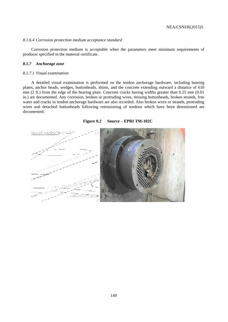
NEA/CSNI/R(2015)5
149
8.1.6.4 Corrosion protection medium acceptance standard
Corrosion protection medium is acceptable when the parameters meet minimum requirements of
producer specified in the material certificate.
8.1.7 Anchorage zone
8.1.7.1 Visual examination
A detailed visual examination is performed on the tendon anchorage hardware, including bearing
plates, anchor heads, wedges, buttonheads, shims, and the concrete extending outward a distance of 610
mm (2 ft.) from the edge of the bearing plate. Concrete cracks having widths greater than 0.25 mm (0.01
in.) are documented. Any corrosion, broken or protruding wires, missing buttonheads, broken strands, free
water and cracks in tendon anchorage hardware are also recorded. Also broken wires or strands, protruding
wires and detached buttonheads following retensioning of tendons which have been detensioned are
documented.
Figure 0.2 Source – EPRI TM-102C

NEA/CSNI/R(2015)5
150
Figure 0.3 Anchor of VVER1000 type prestressing tendon
8.1.7.2 Tendon anchorage areas acceptable limits
The condition of tendon anchorage areas is acceptable if there is no evidence of cracking in anchor
heads, shims, or bearing plates, no evidence of active corrosion, and no evidence of free water. In cases
where broken or unseated wires, broken strands, and detached buttonheads were documented and accepted
during a preservice examination or during a previous in-service examination; they will be acceptable in
subsequent examinations. Cracks in the concrete adjacent to the bearing plates should not exceed 0.01 in.
(0.25 mm) in width.
8.1.8 In-service inspection schedule - US practice
8.1.8.1 Concrete
Concrete is examined in accordance with at 1, 3, and 5 years following the completion of the
containment Structural Integrity Test and every 5 years thereafter. The 1, 3, and 5 year examinations
commence not more than 6 months prior to the specified dates and are completed not more than 6 months
after such dates. If plant operating conditions are such that examination of portions of the concrete cannot
be completed within this stated time interval, examination of those portions may be deferred until the next
regularly-scheduled plant outage.
The 10 year and subsequent examinations commence not more than 1 year prior to the specified dates
and should be completed not more than 1 year after such dates. If plant operating conditions are such that
examination of portions of the concrete cannot be completed within this stated time interval, examination
of those portions may be deferred until the next regularly-scheduled plant outage. Concrete surface areas
affected by a repair/replacement activity shall be examined at 1 year (± 3 months) following completion of
the repair/replacement activity. If plant operating conditions are such that examination of portions of the
concrete cannot be completed within this time interval, examination of those portions may be deferred until
the next regularly-scheduled plant outage.
8.1.8.2 Unbonded post-tensioning systems
Unbonded post-tensioning systems are examined at 1, 3, and 5 years following the completion of the
containment Structural Integrity Test and every 5 years thereafter. The 1, 3, and 5 year examinations
commence not more than 6 months prior to the specified dates and are completed not more than 6 months
FIXING LUG
WASHER
NUT
TENSION ANCHOR
T7T8
T5T6
A A

NEA/CSNI/R(2015)5
151
after such dates. If plant operating conditions are such that examination of portions of the post-tensioning
system cannot be completed within this stated time interval; examination of those portions may be deferred
until the next regularly-scheduled plant outage.
The 10-year and subsequent examinations commence not more than 1 year prior to the specified dates
and are completed not more than 1 year after such dates. If plant operating conditions are such that
examination of portions of the post-tensioning system cannot be completed within this stated time interval,
examination of those portions may be deferred until the next regularly-scheduled plant outage.
8.1.9 Sites with multiple plants
For sites with multiple plants, the examination requirements for the concrete containments may be
modified if the containments utilize the same prestressing system and are essentially identical in design, if
post-tensioning operations for each subsequent containment constructed at the site were completed not
more than 2 years apart, and if the containments are similarly exposed to or protected from the outside
environment. When these conditions are met, the inspection dates and examination requirements may be as
follows:
For the containment with the first Structural Integrity Test, all concrete surface areas (accessible
and suspect), tendon, wire or strand, anchorage hardware and surrounding concrete, corrosion
protection medium, free water shall be performed at 1, 3, and 10 years and every 10 years
thereafter.
Only the examinations of tendon anchorage and corrosion protection medium and free water shall be
performed at 5 and 15 years and every 10 years thereafter.
For each subsequent containment constructed at the site, all concrete surface areas (accessible
and suspect), tendon, wire or strand, anchorage hardware and surrounding concrete, corrosion
protection medium, free water shall be performed at 1, 5, and 15 years and every 10 years
thereafter.
Only the examinations of tendon anchorage and corrosion protection medium and free water shall be
performed at 3 and 10 years and every 10 years thereafter.
8.1.10 In-service inspection schedule - Czech practice
The following ISI are done every year:
Concrete - visual inspection of accessible concrete surface including coating and roof covering,
non-destructive testing of concrete strength,
Liner - visual inspection of accessible surface including coating, non-destructive testing of the
thickness.
ISI of prestressing system is divided into two basic time periods. First period is the first five years of
unit operation. During this period, inspections are done every year - primarily to identify construction
defects. Second period takes till the end of unit operation. During this period, inspections are done every
6th year. Removing of tendons is done every 12
th year beginning last year of the first period. Approx. 2% of
tendons are removed for detail inspection, i.e. one tendon of dome part and 2 tendons of cylindrical part of
containment.

NEA/CSNI/R(2015)5
152
No rules for Multiple Plants are applied due to low number of units operated in the Czech Republic.
8.1.11 Dry air ventilated tendons and greased tendons – Swedish practise
In Sweden there are ten reactors in operation. All the reactor containments consists of an outer bearing
prestressed concrete part, an inner sealing of tight-welded steel liner and an reinforced concrete part to
protect the steel liner. Three of the reactor containments are provided with greased tendons (PWRs
Ringhals 2,3 and 4) and three with dry air ventilated tendons (BWRs Forsmark 1, 2 and 3. The periodic
verification of leak-tight integrity of all the primary reactor containments is performed in accordance with
option A in NRC 10CFR50 appendix J to part 50 (Type A tests). The test interval is fixed and set to three
tests equally distributed over ten years.
The program used for inspection of reactor containments provided with dry air ventilated tendons and
greased tendons is based on NRC Regulatory Guide 1.35. The tendon forces are measured through the lift
off technique for a number of randomly (2-4 % from each group) selected cables every 5th year for the dry
air ventilated tendons and since 1989 every 10th year for the greased tendons. A few individual wires are
taken out to control changes in material properties. Analyses are made on the corrosion protective grease.
8.1.12 Trending prestressing force
RG 1.35.1 [38] provides one method for constructing the upper and lower bounds of prestressing
forces, based on the expected variation in the systemic time-dependent losses in prestressing forces.
Appendix B of RG 1.35.1 provides the upper and lower bounds and the minimum required prestressing
forces as a function of time. To be acceptable, the measured prestressing forces should exceed the
minimum required prestressing force derived from the design requirement to counteract the tensile stresses
in the containment shell induced by the postulated design-basis accident. Another way of predicting
prestressing force is to develop procedures that would enable the utilities to develop trend lines based on
measured forces recorded during all prior inspections.
Title 10, Section 50.55a(b)(2)(viii)(B), of the Code of Federal Regulation (USA) mandates “when
evaluation of consecutive surveillances of prestressing forces for the same tendon or tendons in a group
indicates a trend of prestress loss such that the tendon force(s) would be less than the minimum design
prestress requirements before the next inspection interval, an evaluation must be performed and reported in
the Engineering Evaluation Report as prescribed in IWL–3300”.
The provision essentially mandates corrective actions if, during an inspection, the trending of
prestressing forces based on the prior tendon force measurements indicates that the prestressing force value
is likely to fall below the minimum required value. In addition, in the license renewal applications, the
owners of plants with PCCs are required to perform a time-limited aging analysis of the tendon
prestressing forces to provide assurance that, at the end of the license renewal period, the tendon forces
will meet the licensing basis requirements. These two provisions required the owners of the plants to
perform a trending analysis of prestressing forces. The trend line only reflects the prestressing force values
at tendon anchorages. Trend lines do not represent the minimum prestressing forces along the tendons. The
minimum required prestressing force values must be adjusted to account for friction to compare them with
the values obtained from the trend lines. To maintain consistency when comparing the projected
prestressing forces from the trend lines with the minimum required prestressing forces, the tendons should
be grouped so that they exhibit similar time-dependent characteristics.
The monitoring and trending of prestressing tendon forces assure that the containment has adequate
compression to counteract the tension produced by various loadings for which the containment is designed.
The tension generated by the pressure associated with various postulated accident conditions represents the

NEA/CSNI/R(2015)5
153
major loading for which the prestressing force in a prestressed concrete containment is provided. The
trending of prestressing forces is essential for projecting the potential behaviour of prestressing forces
during plant-life extension. A statistically valid approach recommended for developing a trend line is
essential to performing the regression analysis of the measured prestressing forces.
8.1.13 Future action
The NRC is currently reviewing RG 1.35, RG 1.35.1 and RG 1.90 to assess the need for
improvement. This applies to containments in existing and future plants. The overall objective of this
review is to ensure there is no reduction of the safety margins of concrete containments under operating
and environmental conditions. The review includes operational experience of actual ISI, the latest codes
and standards for post-tensioned containments worldwide, and the latest research results that affect
prestressed losses. The outcome of the review will provide input for an evaluation of the appropriateness of
changes in the three regulatory guides.

NEA/CSNI/R(2015)5
154
8.1.14 Tables from ASME section XI, subsection IWL [6]
TABLE IWL-2500-1
EXAMINATION CATEGORIES
EXAMINATION CATEGORY L-A, CONCRETE
Item No.
Parts Examined
Test or Examination Requirement
Test or Examination Method
Acceptance Standard
Extent of Examination
Frequency of Examination
Deferral of Examination
L1.10 Concrete surface
L1.11 All accessible surface areas [Note (1)]
IWL-2510 General visual IWL-3210 IWL-2510 IWL-2410 NA
L1.12 Suspect areas IWL-2510 Detailed visual IWL-3210 IWL-2510 IWL-2410 NA
L1.13 Inaccessible Below-Grade Areas Note (2)]
IWL-2512(c) IWL-2512(c) [Note (3)]
IWL-3210 IWL-2512(a) IWL-2512(c) NA
NOTES:
(1) Includes concrete surfaces at tendon anchorage areas not selected by IWL-2521 or exempted by IWL-1220(a).
(2) Concrete surfaces exposed to foundation soil, backfill, or ground water.
(3) Method of examination as defined by the Responsible Engineer, based on IWL-2512(b) evaluation.
EXAMINATION CATEGORY L-B, UNBONDED POST-TENSIONING SYSTEM
Item No.
Parts Examined
Test or Examination Requirement
Test or Examination Method
Acceptance Standard
Extent of Examination
Frequency of Examination
Deferral of Examination
L2.10 Tendon IWL-2522 IWL-2522 IWL-3221.1 IWL-2521 IWL-2420 NA
L2.20 Wire or strand IWL-2523 IWL-2523.2 IWL-3221.2 IWL-2523.1 IWL-2420 NA
L2.30 Anchorage hardware and surrounding concrete
IWL-2524 Detailed visual IWL-3221.3 IWL-2524.1 IWL-2420 NA
L2.40 Corrosion protection medium
IWL-2525, IWL-2526
IWL-2525.2(a), IWL-2526
IWL-3221.4 IWL-2525.1(a), IWL-2526
IWL-2420 NA
L2.50 Free water IWL-2525 IWL-2525.2(b) IWL-2525.1(b) IWL-2420 NA
TABLE IWL-2521-1
NUMBER OF TENDONS FOR EXAMINATION
Inspection Period Percentage 1,2 of all Tendons of Each Type3
Required Minimum 1 Number of Each Type
Maximum Required Number of Each Type
1st Year 4 4 10
3rd Year 4 4 10
5th Year 4 4 10
10th Year4 4 2 3 5
NOTES:

NEA/CSNI/R(2015)5
155
(1) Fractional tendon numbers shall be rounded to the next higher integer. Actual number examined shall
not be less than the minimum required number and need not be more than the maximum required number.
(2) The reduced sample size listed for the 10th year and subsequent inspections is applicable only if the
acceptable criteria of IWL-3221.1 have been met for the last three inspections.
(3) A tendon type is defined by its geometry and position in the containment: e.g., hoop, vertical, dome,
helical, and inverted U.
(4) The number and percentage of tendons to be examined every 5th year thereafter shall remain the same.
TABLE IWL-2521-2
AUGMENTED EXAMINATION REQUIREMENTS FOLLOWING POST-TENSIONING
SYSTEM REPAIR/
REPLACEMENT ACTIVITIES
Examination Frequency Number (N) of Tendons of Each Type1 Affected by Repair/Replacement Activity
Required Minimum Percentage of Tendons of Each Type1 Affected by Repair/ Replacement Activity To Be Examined
Augmented Examination Requirement 2,3
Initial Inspection: 1 year (± 3 months) following completion of the Repair/Replacement Activity 4
3 < N < 5%
4%5
Lesser of 4% or 10 tendons
L2.10, L2.30, L2.40 & L2.50
L2.10, L2.20, L2.30, L2.40 & L2.50
Subsequent In-service Inspections scheduled to coincide with IWL-24206 following completion of the Repair/Replacement Activity
3 < N < 5%
4%
Lesser of 4% or
10 tendons
L2.10,L2.30,L2.40 & L2.50
L2.10,L2.20,L2.30,L2.40 & L2.50
NOTES:
(1) The tendon type is defined by its geometry and position in the containment: e.g., hoop, vertical, dome,
helical, and inverted U. If a repair/replacement activity affects a group of tendons, and differing actions are
performed on individual tendons in the group (e.g. tendon replacement, retensioning, and detensioning and
retensioning), each type of action performed on the tendons need not be considered separately when
calculating the number (N) of tendons affected.
(2) A common tendon need not be selected for examination as specified in IWL-2521(b).
(3) Examination requirements are identified in Table IWL-2500-1
(4) If plant operating conditions are such that examination of portions of the post-tensioning system cannot
be completed within this stated time interval, examination of those portions may be deferred until the next
regularly scheduled plant outage.
(5) Where the minimum number of tendons is given as a percentage, fractional tendon numbers shall be
rounded to the next highest integer and shall be considered the minimum number of tendons to be
examined. The percentage is to be applied separately to each type of tendon affected.
(6) The required minimum number of affected tendons of each type to be examined may be reduced to the
lesser of 2% or 5 tendons, if the acceptance criteria of IWL-3221.1 have been met for the last 2 (two)
inspections.

NEA/CSNI/R(2015)5
156
TABLE IWL-2525-1
CORROSION PROTECTION MEDIUM ANALYSIS
Characteristic Test Method Acceptance Limit
Water content ASTM D 95 10 percent maximum
Water soluble chlorides ASTM D 512 [Note (1)] or ASTM D 4327 [Note (1)] 10 ppm maximum
Water soluble nitrates ASTM D 992 [Note (1)] or ASTM D 3867 [Note (1)] or
ASTM D 4327 [Note (1)] or 4110 [Notes (1), (2)] or
4500-NO3 − [Notes (1), (2) ]
10 ppm maximum
Water soluble sulphides APHA 427 [Note (1)] or APHA 4500-S2− [Note (1)]
or 4500-S2− [Notes (1), (2)]
10 ppm maximum
Reserve alkalinity
(Base number)
ASTM D 974 Modified [Note (3)] [Note (4)]
NOTES:
(1) Water Soluble Ion Tests. The inside (bottom and sides) of a one (1) litre beaker, approx. OD 105 mm,
height 145 mm is thoroughly coated with 100 ±10 grams of the sample. The coated beaker is filled with
approximately 900 ml of distilled water and heated in an oven at a controlled temperature of 100°F (38°C)
±2°F (1°C) for 4 hours. The water extraction is tested by the noted test procedures for the appropriate water
soluble ions. Results are reported as PPM (parts/million) in the extracted water.
(2) These referenced test methods are published in “Standard Methods for the Examination of Water and
Wastewater,” published jointly by APHA, AWWA, and WEF. The following specific test methods are
approved for use:
(a) 4110 B. — Ion Chromatography with Chemical Suppression of Effluent Conductivity
(b) 4110 C. — Single-Column Ion Chromatography with Direct Conductivity Detection
(c) 4500-NO3 − E. — Cadmium Reduction Method
(d) 4500-NO3 − F. — Automated Cadmium Reduction Method
(e) 4500-NO3 − H. — Automated Hydrazine Reduction Method
(f) 4500-NO3 − I. — Cadmium Reduction Flow Injection Method
(g) 4500-S2− D. — Methylene Blue Method
(h) 4500-S2− I. — Distillation, Methylene Blue Flow Injection Method
(3) ASTM D 974 Modified. Place 10 g of sample in a 500 ml Erlenmeyer flask. Add 10 cc isopropyl
alcohol and 5 cc toluene. Heat until sample goes into solution. Add 90 cc distilled water and 20 cc 1
Normal (1N) H2SO4. Place solution on a steam bath for 1⁄2 hour. Stir well. Add a few drops of indicator
(1% phenolphthalein) and titrate with 1 Normal (1N) NaOH until the lower layer just turns pink. If acid or
base solutions are not exactly 1N, the exact normalities should be used when calculating the base number.
The Total Base Number (TBN), expressed as milligrams of KOH per gram of sample, is calculated as
follows:
TBN = [20 (NA) − (B)(NB)]56.1/W
Where
B = millilitres NaOH
NA = normality of H2SO4 solution
NB = normality of NaOH solution
W = weight of sample in grams

NEA/CSNI/R(2015)5
157
(4) The base number shall be at least 50% of the as-installed value, unless the as-installed value is 5 or less,
in which case the base number shall be no less than zero. If the tendon duct is filled with a mixture of
materials having various as-installed base numbers, the lowest number shall govern acceptance.
8.2 Bonded tendons
8.2.1 Technical background
This section deals with rationale, operating experience, current practices and further development
related to In-Service Inspection and Surveillance systems for containment with bonded tendons.
8.2.2 Introduction
In concrete structures with unbonded tendons, lift-off tests or other technologies (see EPRI report
[20]) can be used to measure the effective stress in the tendons. For containment prestressing design
involving tendons bonded with cement, it is obvious that the strands cannot be directly inspected, re-
tensioned, or removed. Furthermore, the force in the bonded tendons can’t be directly measured with
current monitoring systems. Following the IAEA guidelines for Surveillance and In-Service Inspection
[24] and the requirements from the concerned Regulators in the world, the choice of bonded ducts for
prestressed concrete containment shall be associated with a dedicated program, including specific and
appropriate instrumentation and pressure test during the operating life of the plant. The aim of this
instrumentation is to provide relevant and quantified data on the remaining prestressing forces in the
tendons and on the integrity of the strands over time.
In addition to periodic visual inspections of concrete surfaces and anchorage hardware, the
surveillance system shall be designed to monitor the following phenomena:
Stress relaxation of prestressing strands,
Delayed concrete strain due to shrinkage and creep,
Decrease of cross sectional area of wire or possible failure of strands, due to corrosion.
We note here that some specific methods dedicated to direct force monitoring for prestressing tendons
were proposed in the past, or are still under development. We can mention systems based on the magneto-
elastic couplings in the steel of the strands (such as TENSMOIMAG® proposed by Freyssinet or the
DYNAMAG [51]). These techniques rely on the monitoring of magnetic properties which are meant to
change with stress. If they have given satisfactory results in laboratory conditions and, for example, on
bridge structures, there is still a need for technical development when it comes to install the
electromagnetic sensors within a concrete wall for bonded tendon monitoring.
The following sections intent to:
Give an overview of the existing feedback from different countries,
Present some guidelines for implementing a In-Service Inspection and Surveillance program,
Address further needs in term of technical development.

NEA/CSNI/R(2015)5
158
8.2.3 Feedback on bonded tendons monitoring
Reference [19] provides a list of selected nuclear power plants fit with embedded sensors for
prestressing level monitoring:
Temelin (Czech Republic, VVER),
EDF fleet (France, PWR),
Tihange and Doel (Belgium, PWR),
Pont Lepreau (Canada, CANDU),
Uljin (Korea, PWR),
Wolsong (Korea, CANDU).
8.2.3.1 U.S.NRC guidance for bonded tendons for PWR and BWR (USA)
For In-Service Inspection of containment with bonded tendons, U.S.NRC provided the regulatory
guides RG 1.90 [39] which has been updated recently with a 30 year-feedback from several countries. It
entails two acceptable alternative methods for monitoring the containment:
Alternative A: a surveillance program based on monitoring the prestressed level by monitoring of
the tensile strains in the wires of bonded tendons and evaluating the prestress level at a section in
the containment structure from readings of appropriately located strain gauges or strain or stress
meters at the section and a pressure test at 1, 3, 5 and then at 10 year-intervals; with a comparison
with Initial Structural Integrity Test (ISIT), performed during the pre-operational test of the
containment and predicted prestress force.
Alternative B: Evaluating elastic response of containment subjected to pressure testing at 1, 3, 5
and then at 5 year-intervals, with a comparison with ISIT, performed during the pre-operational
test of the containment and predicted prestress force.
For both alternatives, the pressure test in the peak pressure PA representative for accidental conditions.
The prestress force inferred from monitoring data is compared with predicted forces calculated for
licensing by taking time-dependant losses of prestress (relaxation of steel and shrinkage/creep of concrete)
into account. Typically, records shall comply with acceptance band of prestress forces over time, which
take overall uncertainties into account (see

NEA/CSNI/R(2015)5
159
Figure 0.4).

NEA/CSNI/R(2015)5
160
Figure 0.4 Typical bands for acceptable prestress levels [39]
In addition, [39] recommends:
A force monitoring for 3 types of tendons left unbonded(in vertical, dome and hoop directions),
Periodic visual examinations of visible parts of the containment and of the prestressing systems.
8.2.3.2 EDF practice for PWR (France)
For French PWR in operation, the technical specifications are based on the code RCC-G [3]. For EPR
series, the technical requirements are stated in the code ETC-C [4].
The French methodology is rather similar with the alternative A of US NRC RG 1.90 [39] but
includes some differences also:
Force monitoring of unbonded test tendons (4 vertical tendons, whereas [39] specifies unbonded
test tendon for hoop and dome tendons as well ),
Monitoring of the prestress level from the prestressing phase to the end of life of the plant, by
using concrete strains as primary records to access to the force in the tendons by calculation,
Monitoring of deformation under pressure (10-year periodic pressure tests at PA, the pressure of
Design-Basis Loss of Coolant Accident),
Visual inspection of the concrete accessible surfaces and tendon anchorage systems, during
pressure tests and in operation. Crack width measurement systems are set in place to monitor the
main cracks during pressure tests. Moreover, in operation, a five-year inspection dedicated to
corrosion marks detection is carried out on seaside power stations.
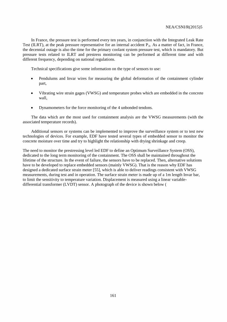
NEA/CSNI/R(2015)5
161
In France, the pressure test is performed every ten years, in conjunction with the Integrated Leak Rate
Test (ILRT), at the peak pressure representative for an internal accident PA. As a matter of fact, in France,
the decennial outage is also the time for the primary coolant system pressure test, which is mandatory. But
pressure tests related to ILRT and prestress monitoring can be performed at different time and with
different frequency, depending on national regulations.
Technical specifications give some information on the type of sensors to use:
Pendulums and Invar wires for measuring the global deformation of the containment cylinder
part,
Vibrating wire strain gages (VWSG) and temperature probes which are embedded in the concrete
wall,
Dynamometers for the force monitoring of the 4 unbonded tendons.
The data which are the most used for containment analysis are the VWSG measurements (with the
associated temperature records).
Additional sensors or systems can be implemented to improve the surveillance system or to test new
technologies of devices. For example, EDF have tested several types of embedded sensor to monitor the
concrete moisture over time and try to highlight the relationship with drying shrinkage and creep.
The need to monitor the prestressing level led EDF to define an Optimum Surveillance System (OSS),
dedicated to the long term monitoring of the containment. The OSS shall be maintained throughout the
lifetime of the structure. In the event of failure, the sensors have to be replaced. Then, alternative solutions
have to be developed to replace embedded sensors (mainly VWSG). That is the reason why EDF has
designed a dedicated surface strain meter [55], which is able to deliver readings consistent with VWSG
measurements, during test and in operation. The surface strain meter is made up of a 1m length Invar bar,
to limit the sensitivity to temperature variation. Displacement is measured using a linear variable-
differential transformer (LVDT) sensor. A photograph of the device is shown below (

NEA/CSNI/R(2015)5
162
Figure 0.5).
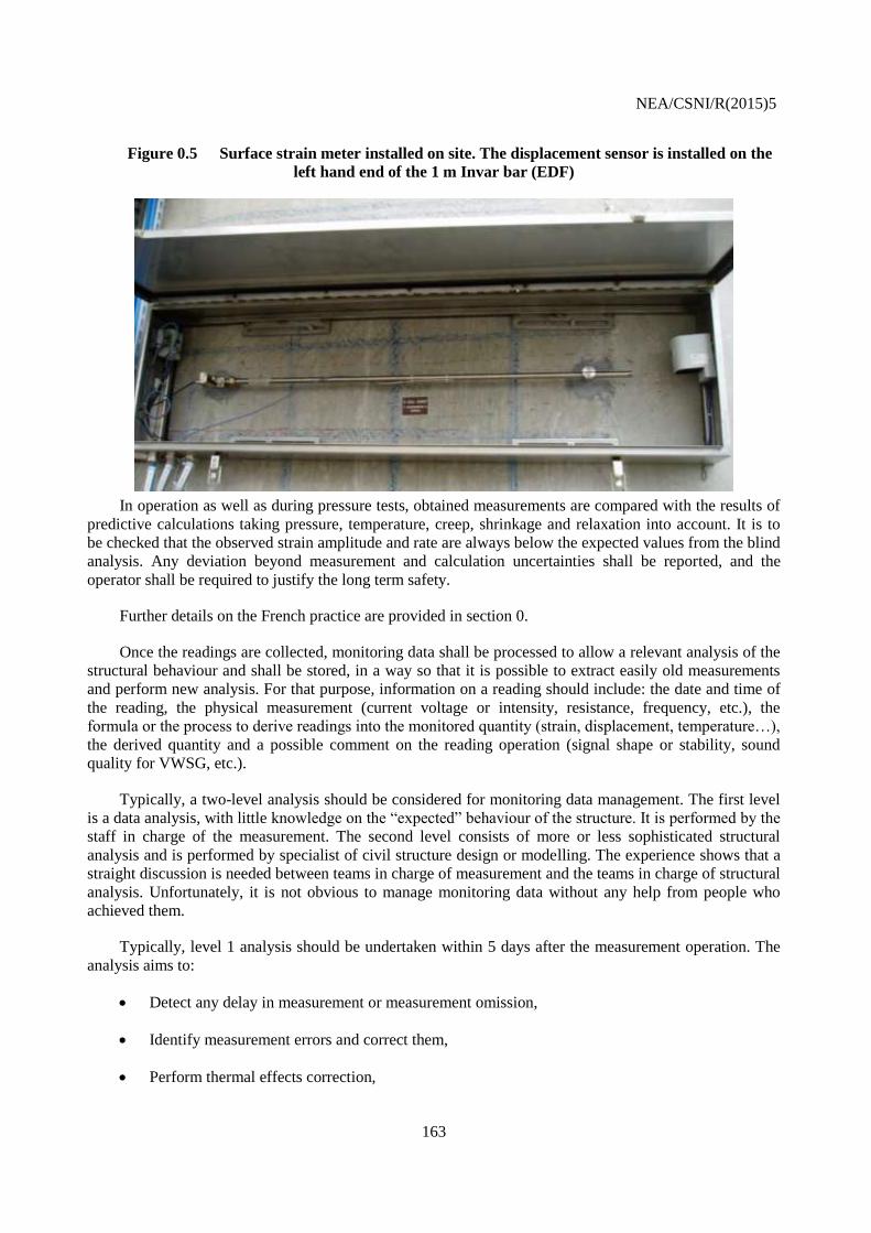
NEA/CSNI/R(2015)5
163
Figure 0.5 Surface strain meter installed on site. The displacement sensor is installed on the
left hand end of the 1 m Invar bar (EDF)
In operation as well as during pressure tests, obtained measurements are compared with the results of
predictive calculations taking pressure, temperature, creep, shrinkage and relaxation into account. It is to
be checked that the observed strain amplitude and rate are always below the expected values from the blind
analysis. Any deviation beyond measurement and calculation uncertainties shall be reported, and the
operator shall be required to justify the long term safety.
Further details on the French practice are provided in section 0.
Once the readings are collected, monitoring data shall be processed to allow a relevant analysis of the
structural behaviour and shall be stored, in a way so that it is possible to extract easily old measurements
and perform new analysis. For that purpose, information on a reading should include: the date and time of
the reading, the physical measurement (current voltage or intensity, resistance, frequency, etc.), the
formula or the process to derive readings into the monitored quantity (strain, displacement, temperature…),
the derived quantity and a possible comment on the reading operation (signal shape or stability, sound
quality for VWSG, etc.).
Typically, a two-level analysis should be considered for monitoring data management. The first level
is a data analysis, with little knowledge on the “expected” behaviour of the structure. It is performed by the
staff in charge of the measurement. The second level consists of more or less sophisticated structural
analysis and is performed by specialist of civil structure design or modelling. The experience shows that a
straight discussion is needed between teams in charge of measurement and the teams in charge of structural
analysis. Unfortunately, it is not obvious to manage monitoring data without any help from people who
achieved them.
Typically, level 1 analysis should be undertaken within 5 days after the measurement operation. The
analysis aims to:
Detect any delay in measurement or measurement omission,
Identify measurement errors and correct them,
Perform thermal effects correction,

NEA/CSNI/R(2015)5
164
Update and maintain the database,
Identify any failed devices,
Identify any faulty mechanical behaviour.
Statistics tools can be used to assess the dispersion of data and to identify possible outliers.
When investigations confirm that a measurement point deviates from the normal dispersion range by
more than the allowed limit a warning or an alert is issued.
The level 2 analysis is dedicated to periodic safety analyses, which are fed by monitoring data and to
alert management, if required. If an alert is raised, an initial set of basic analyses is undertaken to identify
more accurately the structural causes and consequences of the detected anomaly. The Regulator should be
officially informed of the alert as soon as possible and provided with the subsequent action plan within
adequate time period. An assessment is made as to justify the compliance of the containment behaviour
with safety criteria. If required, it can be considered to strengthen the structure, to increase the frequency of
measurement acquisition or to monitor other part or new phenomenon.
8.2.3.3 Canadian approach for CANDU reactors
CSA N287.7 [16] provides requirements related to containment in-service examination and testing for
CANDU reactors. Monitoring of the containment structure during Pre-operational Proof Test (PPT) and
Leakage Rate Test (LRT) is addressed in CSA N287.6 [15]. It is required to instrument containment
structure to enable evaluation of its behaviour during the PPT.
CSA N287.7 [16] requires the containment post-tensioning system that is used as principal
reinforcement to be a subject to an integrity evaluation. Guidelines for instrumented monitoring including
monitoring of the strain, temperature and deformation of the containment structure are provided in the
Standard. The in-service examination program includes visual examinations for visible parts of the
concrete and anchorage systems. The frequency of the in-service examination is at a minimum equal to the
frequency of the ILRT.
The standard also provides guidelines for an indirect method to monitor the post-tensioning system
behaviour, by the use of test beams. The beams are built at the time of containment structure construction
and use the same materials and the same post-tensioning system as the containment structure; concrete
cover and level of prestressing in the beams replicate that of the containment structure. They should be
stored in a manner so that they are exposed to the same environmental conditions. Number of beams that
need to be cast should be calculated to last the service life of the structure as well as to cover possibility of
life extensions. The beams are tested periodically, typically with a minimum frequency equal to that of
ILRT. The tests include flexure tests and destructive tests to confirm effectiveness of corrosion preventive
medium. Also, the lift-off tests are performed on the beams cast with unbonded tendons to estimate time
depending prestressing force losses. The Test beam method is also used in other countries (e.g. Finland,
Belgium) to evaluate integrity of the bonded post-tensioning system.
8.2.3.4 Chinese practice
Chinese experiences related to monitoring of containments with bonded tendons can be found in [57]
and [63]. Both articles deal with pre-operational integrity test reports on Chinese PWR, and show
applications of French and American practices, referring to [3], [5] and [39].

NEA/CSNI/R(2015)5
165
8.2.3.5 Belgian practice
Belgian practice, for instance reported in [28], refers to the 1977 version of [39] (alternative “A” for
the prestress level monitoring, to [5] and [6]. It includes also the use of test beams, such as in Canadian
specifications. Due to the embedded sensors failure (mostly VWSG), surface strain meters have also been
installed.
8.2.3.6 South African practice
The design of the ESKOM containment structures at Koeberg is similar to the French 900 MW PWR
series. The concrete structures are monitored and are required to meet the criteria of ASME XI [6]
subsection IWL with some exceptions due the cement grouting of the tendons, which makes it impossible
to comply with the prescribed method of inspection as described in ASME XI [6]. So, the Koeberg
monitoring program is a kind of mix between ASME XI [6] requirements and French practice.
The containment structures are subject to regular monitoring, which enable the performance of the
containment structures to be evaluated during routine in-service tests. The monitoring system includes the
same devices as used in France: topographical reference marks on the upper and lower rafts (since Koeberg
station is built on seismic isolators), vertical invar wires, pendulums, embedded VWSG and
thermocouples, dynamometers set on unbonded tendons.
The external concrete surfaces of the containment structures at Koeberg station are subject to
examination in accordance with ASME XI [6] subsections IWL and IWE. Due to the accelerated
degradation of the concrete integrity at Koeberg power station, this examination shall be performed during
every refuelling outage. The metallic liner is visually inspected during every second refuelling outage.
In-service testing of the containment structure is monitored by performing leak rate tests based on
ASME Operation and Maintenance code [7] and 10CFR50 Appendix J requirements. The behaviour of the
containment is also assessed by recording measurements from the monitoring devices acquired during the
pressure tests.
8.2.3.7 Swiss practice
With one exception all concrete structures of the Swiss NPPS are conventionally reinforced. For
bearing the roof loads the uppermost 5 metres of the cylindrical outer wall of the reactor buildings Beznau
I and II (secondary containments) are prestressed. The secondary containments are not designed to resist
internal pressure, these loads will be absorbed by the primary steel containments.
14 Groups of 4 parallel bonded tendons (system BBRV) are embedded all around the secondary
containments. The tendons consist of 43 wires with diameter 6 mm per wire. The original design bases for
the reactor buildings were:
ASME code, Section III [5],
Safety code for Design, Fabrication and Maintenance of Containment Structures for Stationary
Atomic Power Reactors, ASME,
Codes SIA 160/1956, SIA 161/1956, SIA 162/1956, Swiss Society of Engineers and Architects.
The tendons are examined within the scope of the ageing management program. Main inspections are
done every 10 years with interim inspections in between after 5 years. Amongst others the following tests
are carried out:

NEA/CSNI/R(2015)5
166
Visual inspections of the concrete surfaces,
Removing of concrete drill cores and testing of the concrete characteristics in the lab,
Potential field measurements to detect corrosion in the tendons,
Selective exposing and visual inspections of the anchor heads.
Up to now no signs for ongoing corrosion in the tendons were found. The inspected exposed anchor
heads were in faultless state.
8.2.3.8 Finnish practice
8.2.3.8.1 Operating plants in Olkiluoto
Currently there are two operating units with prestressed containments with unbonded tendons OL1
(1978) and OL2 (1980) Asea-Atom Ab BWR 660 MW (updated to 880MW). The units have different
prestressing systems: The OL1-unit containment has a VSL-system with Bridon Supa LR of 13 mm strands
and the OL2-unit has a BBRV system with tendons of single 7 mm wires. The tendons have been bonded
with cement grout.
Containment buildings are tested (A-test) with 0.4 MPa of overpressure. In addition to pressure,
temperature and humidity are measured during the test.
Strains are measured with an ISI system (strain gauges MDD 53 a). The measured strains are
compared with theoretical values acquired from finite element analysis. Before the test and during
maximum pressure, a visual inspection is made and a cracking map is created. Over 0.05 mm cracks are
recorded. Initial pressure test was at 0.525 MPa ABS (1.15 times the design over pressure) and the first A-
test with 0.4 MPa overpressure.
Integrity test details such as frequency and pressure have been set according to principles stipulated in
American regulations 10 CFR, Part 50, Appendix J.
Additional tests and inspections have been done with NDT equipment. 3D FEM analyses have been
done in order to verify test results.
8.2.3.8.2 OL3 under construction
The ISI-system of the containment of the OL3 EPR unit in Olkiluoto is based on French practice with
displacement, strain, temperature, humidity measurement of containment and force measurement of the
four unbonded tendons. An additional optical system was implemented to detect possible excess strains of
the liner. Humidity measurements of the containment wall will be verified with test samples stored in
reactor building annulus. One test sample consists 1.3 m long 150 mm diameter cylinder with 100 mm long
parts. One end of cylinder is left open while other surfaces are connected to tight mould to avoid loss of
moisture. Humidity of length on containment wall will be determined by weighting each part.
8.2.3.8.3 Regulations for new plants
Finnish legislation for nuclear power plants is based on the Nuclear Energy Act [30]. Design and
construction of buildings and structures shall adhere to Land Use and the Building Act [21]. Radiation and
Nuclear Safety Authority (STUK) is authorized to set safety regulations for design, construction and
operation. The Regulatory Guides on Nuclear Safety (YVL-Guides) have been completely updated in
2013. Guide [31] sets forth requirements and instructions for containment buildings. Guide [32] sets

NEA/CSNI/R(2015)5
167
requirements for design, materials and construction and ISI for containment building. Other standards
mentioned in YVL codes are:
Eurocode standard for loads, concrete and steel structures EN 1990 [9], EN 1991 [10], EN 1992
[11], EN 1993 [14],
SFS-EN 206-1 Concrete. Part 1: Specification, performance, production and conformity [29],
ETAG 013, Guideline for European Technical Approval of Post-Tensioning Kits for Prestressing
of Structures [17],
ASME Boiler and Pressure Vessel Code III Division 2, Code for Concrete Containments [5],
USNRC Regulatory Guide 1.90, In-service inspection of prestressed concrete containment
structures with unbonded tendons [39].
General rules for containment building according to new regulatory guides [31] and [32] are as
follows:
A test plan shall be made for pressure and leak tightness test and shall include:
- The deformations and the strains in different pressure levels (predictive analysis)
- Retrieving of the deformations and the strains (measurements)
- Mapping of the cracks
- Temperatures, amounts of leaks
Pressure test for 1.15Pd before commissioning
Periodical leak tightness test at accident pressure for containment building and penetrations.
Adequate instrumentation for retrieving deformations, strains, temperatures and moisture of base
slab and containment during pressure and leak tightness tests.
Tendon force for some tendons must be measurable.
ISI program shall be delivered to regulator for approval and shall include:
Periodical and during testing inspections for deformations, strains and leak tightness
Periodical inspections of tendons and anchors
Assessment for essential structures with testing or with other reliable means (core drill samples,
environmental samples, NDT, etc.)
ASME III Div.2 [5] and USNRC Regulatory Guide 1.90 [39] are mentioned as useful reference for
pressure and leak tightness program.

NEA/CSNI/R(2015)5
168
8.2.3.9 Swedish Practise
In Sweden there are ten reactors in operation. All the reactor containments consists of an outer
bearing prestressed concrete part, an inner sealing of tight-welded steel liner and an reinforced concrete
part to protect the steel liner. Four of the reactor containments are provided with bonded tendons (BWRs
Ringhals 1 and Oskarshamn 1, 2 and 3).
The periodic verification of leak-tight integrity of all the primary reactor containments is performed in
accordance with option A in NRC 10CFR50 appendix J to part 50 (Type A tests). The test interval is fixed
and set to three tests equally distributed over ten years.
The visual inspections of reactor containments provided with bonded tendons are supplemented with
crack mapping and in some cases also with the “hammer-method”. The anchor and the concrete
surrounding the anchor are inspected visually. The tendon forces can’t be measured.
8.2.3.10 Summary - bonded tendons monitoring
When the country is adopting bonded tendons, instrumentation of the different parts of the
containment is one of the keys to demonstrate, to the satisfaction of the regulator, that the prestressing
forces comply with the design requirements. The reliability and longevity of the instruments and also the
data collection and interpretation are the critical aspects of monitoring.
Full pressure tests are often considered to complement the monitoring of the delayed strain. It is then
important to keep carefully all the data acquired during the previous test to be able to get the overall trend
of the observed phenomena.
The acceptance criteria are often related to the design calculations or blind predictions results. It is
necessary to confirm the accuracy of the predictive analysis including ensuring that the codes used are
appropriate, ambient conditions (i.e. temperature, humidity) and material properties used are
representative. The consistency between the expected and observed containment behaviours is considered
as a satisfying proof of compliance with safety requirement.
Periodic visual inspection and direct force monitoring (on a few unbonded tendon) are considered as
well.
When interpreting results of the beams testing and projecting them to concrete containment structure,
the following should be well understood and taken into account:
Environment of exposure for the beams is not the same as environment that containment structure
is exposed to as the beams can only be exposed to environmental conditions outside or operating
condition inside the containment structure;
The major contributors to the prestressing force loss such as creep and shrinkage greatly depend
on the size of the concrete element; therefore prestressing force loss estimated by testing the
beams do not directly represent the prestressing force losses of the massive concrete containment
structure.
As an illustration, Table 0.1 below presents an outlook of the specifications for American and French
in-service inspection.
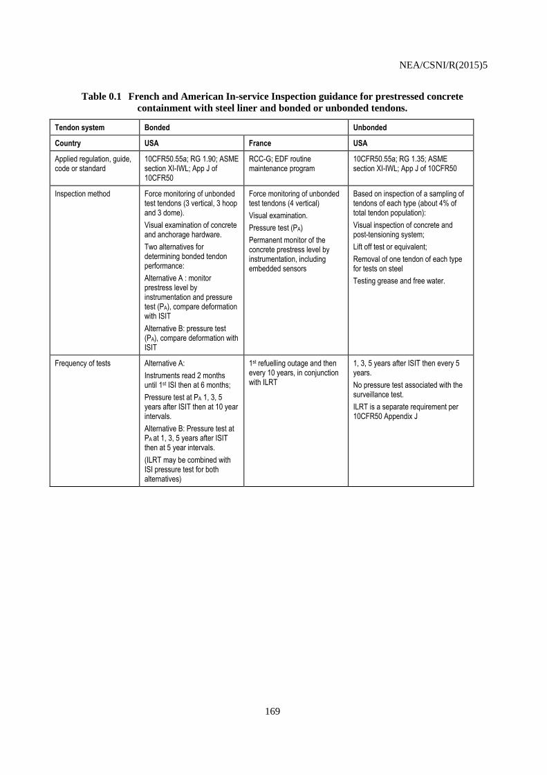
NEA/CSNI/R(2015)5
169
Table 0.1 French and American In-service Inspection guidance for prestressed concrete
containment with steel liner and bonded or unbonded tendons.
Tendon system Bonded Unbonded
Country USA France USA
Applied regulation, guide, code or standard
10CFR50.55a; RG 1.90; ASME section XI-IWL; App J of 10CFR50
RCC-G; EDF routine maintenance program
10CFR50.55a; RG 1.35; ASME section XI-IWL; App J of 10CFR50
Inspection method Force monitoring of unbonded test tendons (3 vertical, 3 hoop and 3 dome).
Visual examination of concrete and anchorage hardware.
Two alternatives for determining bonded tendon performance:
Alternative A : monitor prestress level by instrumentation and pressure test (PA), compare deformation with ISIT
Alternative B: pressure test (PA), compare deformation with ISIT
Force monitoring of unbonded test tendons (4 vertical)
Visual examination.
Pressure test (PA)
Permanent monitor of the concrete prestress level by instrumentation, including embedded sensors
Based on inspection of a sampling of tendons of each type (about 4% of total tendon population):
Visual inspection of concrete and post-tensioning system;
Lift off test or equivalent;
Removal of one tendon of each type for tests on steel
Testing grease and free water.
Frequency of tests Alternative A:
Instruments read 2 months until 1st ISI then at 6 months;
Pressure test at PA 1, 3, 5 years after ISIT then at 10 year intervals.
Alternative B: Pressure test at PA at 1, 3, 5 years after ISIT then at 5 year intervals.
(ILRT may be combined with ISI pressure test for both alternatives)
1st refuelling outage and then every 10 years, in conjunction with ILRT
1, 3, 5 years after ISIT then every 5 years.
No pressure test associated with the surveillance test.
ILRT is a separate requirement per 10CFR50 Appendix J

NEA/CSNI/R(2015)5
170
Tendon system Bonded Unbonded
Country USA France USA
Acceptance criteria Alternative A:
Verify prestress forces are within the predicted range (8% band).
Check unbonded tendon forces.
Linear and reversible deformation
Limited cracking and other defects
Report abnormal trend and implement corrective action
Alternative B (during test):
Limited increase of containment deformation as compared to ISIT
Verify prestress force are within the predicted range
Check unbonded tendon forces
Limited cracking and other defects
Linear and reversible deformation
Report abnormal trend and implement corrective action
Verify unbonded tendon force
In operation:
No abnormal trend in the records consistency with delayed strain predictions
Pressure test:
Linearity, reversibility consistent with design predictions
Limited cracks and other defects
Prestress force within predictive limit (average of tendon forces and individual force)
Tensile strength tests on removed tendon (greater than ultimate tensile strength)
Grease test criteria from ASME
8.2.4 Guidelines for bonded tendons monitoring
The recommendations provided for a typical ISI program for containment with bonded cables are
based on the current international practice. One should keep in mind that, if needed, designer and/or
operator will have to adapt the surveillance method to the national context (nuclear regulation and
industrial background) of the country where the NPP is built. Typically, the determination of the schedule
of the ISI program and the associated acceptance criteria have to be formally approved by the Safety
Authority/Regulatory body involved in the assessment of the power plant. Requirements may vary from
one country to another.
All the recommendations hereafter are to be considered as technical proposals derived from an
international feedback.
8.2.4.1 General provisions
In case of containment prestressing system with cement bonded tendons, it is recommended to include
in the ISI program the following items:
Force monitoring of some tendons left unbonded;
Concrete containment structure monitoring for performance of bonded tendons;
Visual inspection of concrete and visible part of the prestressing system.

NEA/CSNI/R(2015)5
171
If the performance of bonded tendons is assessed through a monitoring containment prestress level
during operating time (close to the Alternative A in [39]), it is recommended to start data collection as soon
as possible during the construction and especially during the tensioning phase of the cables. Despite the
additional cost involved, applying this option provides baseline information (as recommended in [24]) and
more reliable insights on the actual behaviour of the structure [54]. For that purpose, a permanent real-time
monitoring system seems more convenient to acquire and to process the data.
If case of an existing plant showing some gaps in its monitoring records (period without
measurement, for example), the following possible solutions might be considered:
Use available information from other similar plants (same structural design and similar
materials), if any;
Fill the gap using structural analysis, fed with available monitoring data;
Carry out laboratory tests on representative samples to determine the actual creep and shrinkage
laws and incorporate through modelling (see [47] for an example). Without any data at the
containment scale, the prediction capability of such a method might be limited to a few years, due
to the current performances of materials and structural analysis tools.
As a reminder, in every situation for civil structure long term surveillance, we recommend to select
the monitoring devices based on their performance, ease of use, robustness and reliability. Feedback is of
course of great interest to check if a system meets these specifications. [8] may be used as guidelines to
specify and to select new instrumentation devices.
Before being set in place, each sensor should be calibrated (if applicable) with a dedicated calibration
report. The minimum requirement is to get from the vendor a data sheet stating a relevant metrological
control for each sensor.
Data management is an issue to be addressed with caution. All the data relative to sensor fabrication
and all the records from the devices shall be stored for the entire operating life of the plant. The attention is
drawn to the fact that this requirement is not so easy to meet, because the operating life could reach 60
years or more. A dedicated system has to be developed by the owner for that purpose, with regular backup
and upgrade procedure.
Moreover, each sensor or acquisition system should be regularly checked and cleaned and, if possible,
calibrated, repaired or changed. When the repair is not possible (for embedded sensors, for instance), an
alternative system should be set in place to provide an information consistent with that which was
delivered by the failed device (for example the surface strain meter developed by EDF, see section 0).
8.2.4.2 Force monitoring in unbonded tendons
A few tendons can be left unbonded to allow for direct force measurements.
Apart from lift-off testing, alternative methods can be used to measure a force in a tendon, such as
hydraulic load cells or dynamometer based vibrating wire sensing or on linear variable-differential
transformer (LVDT). Generally, the time before failure allows acquiring enough data so that a relaxation
law fitting is possible. But it is difficult to rely on these sensors for all the expected operation time of the
plant. It is to point out that these dynamometers cannot be replaced in case of failure.
If needed, lift off can be considered to check the actual force in the unbonded tendons.

NEA/CSNI/R(2015)5
172
8.2.4.2.1 Location
Typically, minimum requirement is to have 3 vertical tendons along the axis of the cylinder available
for force monitoring. Following the way the monitoring data are used in the overall safety assessment,
more tendons can be considered, including tendons in the hoop direction or in the dome.
8.2.4.2.2 Frequency
The owner should define the frequency at which the force monitoring will be conducted. This
frequency should be based on the final use of the results of the measurements and the capability of the
measurement system. Of course, dynamometers enable more frequent measurements with fewer
disturbances for the structure.
The established frequency shall be submitted to the national Regulator for approval.
8.2.4.2.3 Instrument specifications
Requirements on the range and the precision of the measurement system mainly depend on the
expected tension variation in the tendon. The system should be operated normally within the range of
expected site temperature (typically -20°C /+60°C).
Temperature in the containment cylinder shall be measured also, for further data processing.
Accuracy below 1.5% of the minimum ultimate force is recommended.
8.2.4.2.4 Data processing
Raw data requires interpretation. A first step is to assess the effect of volumetric changes in concrete
due to temperature on the prestress force.
8.2.4.2.5 Possible acceptance criteria
The criteria listed below are given as examples. Acceptance criteria shall be based on the relevant
regulations for each country and on regulator’s review and assessment.
It is recommended to establish a band of acceptable prestress levels similar to that illustrated in

NEA/CSNI/R(2015)5
173
Figure 0.4. A possible criterion proposed in [39] is not to exceed 8% of the initial prestressing force
at a section after considering the short term losses (resulting from elastic shortening, anchorage take-up,
and friction). The minimum criterion is to establish at the design stage a lower bound of the acceptable
prestress force. Whatever the case, the comparison between readings and acceptable force should account
for measurement uncertainties.
The owner should report any force monitoring output indicating a prestress force below the lower
acceptable limit.
8.2.4.3 Monitoring for performance of bonded tendons
As the prestress force cannot be directly measured with current technologies in cement bonded
tendons, their performances are assessed through indirect method.
Evaluating directly strand strain requires careful attention during instrumentation installation. There is
little feedback information related to this technique (accuracy, drift, ease of use, reliability, robustness or
possible repair during operation). For the reason, it is recommended to assess tendon prestress level by
means of two types of instrumentation:
Embedded strain meters (or stress meters if sufficient accuracy is demonstrated), set up in
different sections of the concrete containment;
Displacement measuring instrumentation (pendulum, plumb lines, “long range” extensometers,
etc.) attached directly to the containment shell.
Embedded and “external” sensors should be used together. This redundancy will help to validate
measurements by crossed controls and to confirm possible measurement error during test or over operating
time.
The use of evaluation method based on strain measurement involves a good understanding of the
contributing factors to the observed behaviour: elastic shortening, response under test pressure, shrinkage,
creep and thermal strain.
Generally, the basic interpretation of the results relies on the devices located at sections away from
structural discontinuities.
8.2.4.3.1 Location and quantity of instrumentation
Strain or stress meter and temperature probes should be installed in sufficient numbers at strategic
locations and relevant direction in the containment structure so that loss in prestress levels can be assessed
in an accurate and reliable way. The temperature monitoring is useful for isolating thermal effects and
inferring delayed or elastic strains. The containment designer should be involved in the determination of
the layout of the sensors. Moreover, sufficient redundancy in the instrumentation should be provided to
evaluate anomalous readings and to isolate malfunctioning gauges. Currently, the selection of
instrumentation types, locations and quantities are under the responsibility of the plant owner, but this task
should be done in close association with the designer of the containment.
It is recommended to combine temperature probes (or thermocouples) with strain meters so that a
temperature reading is available for all of the strain records.
It is recommended that the directions of the monitored strains match the directions of the prestressing
cables, to get a better evaluation of the principal strains in the structure. The distribution of sensors through
a section depends on its thickness and on the expected distribution of strain within the structure at this

NEA/CSNI/R(2015)5
174
section. Basically, the sensors will be set in the middle of a wall section. But if needed, one can considered
that sensors are installed near the inner and the outer face of the wall (see

NEA/CSNI/R(2015)5
175
Figure 0.6).

NEA/CSNI/R(2015)5
176
Figure 0.6 Example of VWSG and temperature probe arrangement within a containment
wall
These local measurement devices are complemented by other “external” instruments, such as
pendulum, wire or inclinometer (tilt meter).
The minimum recommendations for the sensors quantities and locations are detailed hereafter:
The containment should be instrumented at different levels and in different areas: basemat, gusset,
cylinder, ring girder, buttresses for prestressing, equipment hatch, large penetrations and dome (see

NEA/CSNI/R(2015)5
177
Figure 0.7 and Figure 0.8);
The embedded sensors should be installed along at least 3 vertical lines of the cylinder, at 3
approximately equally spaced azimuths. These lines are extended to the dome and the basemat,
and are away from structural discontinuities. They are complemented with other vertical
measurement lines along buttresses (Figure 0.8);
It is recommended to measure the “overall” (in contrast to “local” strain) displacements and
deflection along the 3 vertical lines mentioned just above;
The basemat is instrumented at its centre and at different radii, as shown at Figure 0.9. It is recommended
to have two layers of sensors within the thickness of the slab, in order to assess any possible deflection
under settlement and test pressure (see

NEA/CSNI/R(2015)5
178
Figure 0.7);
The dome and the ring girder are instrumented as shown at

NEA/CSNI/R(2015)5
179
Figure 0.7 and Figure 0.9;
The cylinder and the gusset are instrumented as shown at

NEA/CSNI/R(2015)5
180
Figure 0.7 and Figure 0.8;
The equipment hatch is monitored through extensometers installed following the vertical and the
horizontal axis.

NEA/CSNI/R(2015)5
181
Figure 0.7 Typical embedded sensors layout in a vertical cross section of a containment
structure
Figure 0.8 Typical embedded sensors layout on a developed view of the cylinder

NEA/CSNI/R(2015)5
182
Figure 0.9 Typical embedded sensors layout in the dome (top view)
Figure 0.10 Typical embedded sensors layout in the raft (top view)
)
8.2.4.3.2 Frequency
The periodicity of measurement is to adapt to the monitored phenomena. The required frequncy for
data acquisition is higher in test conditions than in operating conditions. Of course, a real time monitoring
enhances the capability to manage the data acquisition and then allows a faster analysis of the behaviour of
the containment in any condition.

NEA/CSNI/R(2015)5
183
Pressure test
10-year period is the maximum acceptable interval between two consecutive pressure tests dedicated
to prestress level monitoring (ILRT program may include different time frames). During the test, it is
recommended to acquire data at intermediate pressure levels, and not to limit the acquisition to PA stage.
Typically, records for PA/2 level should be done during inflating and deflating of the containment.
Delayed strain assessment
It is recommended to adapt the measurement frequency to the phenomena, for example to creep and
shrinkage rate. In normal operating conditions, the minimum recommendation to collect readings from all
the monitoring system is:
Every 3 months if the measurement are performed manually;
Every 2 weeks if the data are automatically acquired.
8.2.4.3.3 Instrument specifications
The requirements over instrumental range and precision are derived from:
The expected behaviour of the structure;
The ambient conditions of the sensors;
The criteria to apply;
The provisions provided by the numerical calculations results with which the measurements
would be compared.
Materials used in the strain or stress meters are specifically chosen to minimize or to self-compensate
the temperature effects on the measurements. However, slight temperature effects can persist, and a
temperature correction is to apply. The correction factor shall be specified by the manufacturer.
The regular maintenance checks of the monitoring system (involved in pressure tests preparation but
also during normal operation) help to ensure satisfactory instrument performances are kept over time.
Some minimal guidance on range and accuracy of the measurement system (not only the sensors) is
provided in Table 0.2 below.

NEA/CSNI/R(2015)5
184
Table 0.2 Minimum instrument specifications.
Phenomenon Range of measurement Accuracy of the measurement system
Pressure (for pressure test) Including 0 barg and PA, no more than 4xPA +/- 2% of PA
Temperature -20°C / 60°C +/- 1°C
Strain (ex: embedded strain meter) About 3000.E-6
+/-5% of the maximum expected or observed value or 10.E-6, whichever is greater
Vertical displacement (ex: Invar wire) 80 mm +/- 1 mm
Horizontal or radial displacement (ex: pendulum)
40 mm +/- 1 mm
8.2.4.3.4 Data processing
After appropriate methods and instruments are employed for measurement, the measured data should
be analysed to determine an average stress and an average prestressing force at a section.
The surveillance results obtained are related to the conditions, involving thermal conditions, in which
the raw measurements were achieved. In complement to the direct temperature effect on the measurement
system, the engineer in charge of the structure behaviour assessment has to evaluate accurately the
reversible thermal volumetric changes of the structure (through the temperature readings), and to subtract
them from the associated raw records.
Various procedures can be proposed for this thermal correction. The first and simplest approach is the
thermo-differential correction method. The corrected values of strain εcorr are derived from the raw strain
εraw (deduced from readings) by using the following formula:
εcorr = εraw + αs.(T-T0) – αc.(Tm – Tm0) Eq. 0.1
With:
T: temperature recorded with the associated thermocouple at the time t (°C)
Tm: mean temperature of the wall (°C)
T0: initial temperature recorded with the associated thermocouple (°C)
Tm0: mean temperature of the wall at the initial time (°C)
αs: thermal expansion factor of the sensors (°C-1
). Typically, αs ranges between 10 and 12.E-6 °C-1
αc: concrete thermal expansion factor (°C-1
). Typically, αc ranges between 7 and 13.E-6 °C-1
Other methods can be proposed. We can mention the EDF’s practice, inspired by dam surveillance
(see [28] pp 105-106). This method consists in a statistical data processing, based on a multiple linear
regression analysis in which temperature and time are the explanatory variables.
If the measurements made on test beams are used as complement to the structural monitoring, those
measurements should be included in the raw data processing.
When extrapolations are needed, different approaches can be undertaken: rather simple, relying on
creep and shrinkage laws from standards [54], [48] or by finite element analysis [46].
It is recommended to provide a periodic report including the measurements and a diagnosis on the
actual conditions of the containment, with a comparison between measurements and design criteria
assumptions. The minimum outline of the report should include:

NEA/CSNI/R(2015)5
185
The layout of the instrumentation;
A description of the pressure test procedures, if any;
A comparison between measured values and response predicted by analysis including tolerance
and accuracy of both measurements and numerical model;
An evaluation of any deviation (such as test results exceeding allowable limits) and need for
correctives actions.
8.2.4.3.5 Possible acceptance criteria
The criteria listed below are given as examples. Acceptance criteria shall be based on the relevant
regulations for each country and on regulator’s review and assessment.
Limits of acceptable prestress levels, similar to that illustrated in

NEA/CSNI/R(2015)5
186
Figure 0.4, should be established for all the operation time of the plant.
The difference between strains measured during periodic pressure test and strains observed during the
Initial Structural Integrity Test (ISIT) should not exceed an acceptable threshold. This limit may vary over
the countries. The various sources of uncertainties should be taken into account in the data analysis.
The owner should report any measurement indicating a strain exceeding the pre-set acceptable limit.
8.2.4.4 Visual inspections
In addition to monitoring of the concrete containment structure using strategically located
instrumentation, visual inspection of accessible areas inside and outside of the containment structure
should be conducted periodically.
8.2.4.4.1 Location
Visual inspections should concentrate on critical areas, such as anchor regions of post-tensioning
system, joints, areas of high stress concentration as identified by analysis. In addition, those areas where
leakage was detected during ILRT and areas where problems were found previously should be visually
inspected. Areas where repairs were performed should also form part of periodic inspection to ensure
integrity of repairs (e.g. ASME XI section IWL requires “augmented” inspection for such areas).
8.2.4.4.2 Frequency
It is prudent to perform visual inspection during every outage. As a minimum, periodic inspection of
concrete containment structure are typically performed every 5 or 6 years, (e.g. [2] recommends visual
inspection of safety related structures to be performed every 5 years, while [16] has a minimum
requirement of 6 years between inspections. For seaside sites, it is recommended to adapt the frequency to
the risk of corrosion which is more likely to occur in a more aggressive atmosphere.
It is beneficial to perform visual inspection of the external surfaces of the containment structure
during the Proof Pressure Test and Integrated Leakage Rate Tests in order to observe the behaviour of the
structure under pressure. Detection of the leak paths associated with concrete structure or its components
may be associated with cracks, areas of unconsolidated concrete or other discontinuities or defects in the
structure.
8.2.4.4.3 Specifications
Some useful guidance for conducting a visual inspection of concrete structures: definitions,
illustrations, checklist for routine inspection, etc. is provided in [1].
The system should be able to detect and characterize the crack patterns on the visible concrete
surfaces of the containment. Remote systems should be considered in case of difficult access of areas by
the inspectors.
Depending on the configuration, remote visual inspection should be considered to monitor the critical
parts of the containment which are not easily accessible.
Pictures with appropriate resolution should be taken of the main cracks and visible defects, in order to
record the actual conditions and to get a relevant database for the patterns evolution. Crack maps should
be created.
Cracks and cracks patterns should be reported based on the observed lengths, spacing and widths. The
scope of the concrete conditions to report has to be defined prior to the inspection. For example, any cracks
with a width greater than 0.3 mm or a length greater than 200 mm may be considered as reportable.

NEA/CSNI/R(2015)5
187
In complement to cracks, defects such as stains, spalling, pop outs, corrosion marks and visible rusted
rebar may also be reportable.
During pressure tests, the widths of the main cracks should be monitored with temporary
displacement sensors with adequate accuracy (less than 0.1 mm).
8.2.4.4.4 Data processing
The reportable cracks and defects should be mapped to provide an overview of the containment
conditions.
Basic data processing can be considered to assess the cracks or defects distribution and their evolution
over time.
8.2.4.4.5 Possible acceptance criteria and reportable situations
The criteria listed below are given as examples. Acceptance criteria shall be based on the relevant
regulations for each country and on regulator’s review and assessment.
Guidelines provided by [2] for acceptance criteria for nuclear safety related structures can be applied
for containment structure. However, these are generic and more precise criteria may need to be established
so that functions of the structure as well as exposure conditions of a particular part of the containment
structure are taken into consideration.
[2] provides tiered approach; if considered necessary based on results of visual inspection, other
techniques, such as non-destructive / destructive tests or analysis may be used to identify the cause and
extent of the degradation.
The following situations should be considered as reportable by the owner of the plant:
At the structurally critical areas, any significant decrease in the spacing or any significant
increase in the widths of cracks compared to those observed during the ISIT at zero pressure after
depressurization;
Any significant degradation or movement of the anchor hardware.
8.2.4.5 Corrosion detection
Heat-treated steel is sensitive to stress-induced corrosion, which may lead to localized, non-ductile
failure of the tendon. Main functions of the grout are to protect prestressing steel from corrosion and to
bond the tendons to the surrounding concrete. Due to the bond between tendon and grout, bonded tendons
are less vulnerable to local damage than unbonded ones because if tendon breaks, part of the prestress
remains transmitted to the concrete.
The possibility of tendon corrosion is low if the grout and concrete surrounding tendons are in good
condition. The presence of voids within the tendon duct might be due to blockages, inadequate grouting
procedures, grouting material problems, and construction oversight. Inadequate grouting may not fully
protect the tendons against corrosion and hence reduce the durability, possibly causing the loss of the
cross-section and breakage of the tendons. In grouts with high water/cement ratio, bleeding may occur,
causing formation of pockets of water, particularly in the elevated areas of the prestressing ducts. High
operating and ambient temperatures will tend to facilitate corrosion once it is active.

NEA/CSNI/R(2015)5
188
Techniques for detection of corrosion in post-tensioning tendons are available as discussed below and
have been successfully used on civil structures (e.g. bridges). However, corrosion detection methods are
not widely used in nuclear industry. Large areas of the containment structure would have to be covered to
perform thorough investigation. If investigation is performed locally, detecting corrosion would raise
concern for the rest of the structure; however, if no corrosion is detected it would only be applicable to the
area tested. With instrumented monitoring, local capacity reduction would be detected by the sensors of
sufficient accuracy that are located strategically in appropriate quantities. Then corrosion detection
methods can be applied to further investigate identified location. Corrosion detection can also be used if
there is a concern with the quality of grouting.
Ultrasonic tomography is successfully used to detect voids in the grout of the post-tensioning system.
It is based on the ultrasonic echo method. The transducers applied to the concrete surface introduce low
frequency pulses of shear waves. A 3-D tomographer system with transducers sending and receiving the
reflected pulse is able to scan and detect the voids in the grout at a distance of up to about 0.5 m from the
surface depending on the amount of reinforcing steel (i.e. heavy reinforcement reduces “visibility”).
Post-Tech® Corrosion Evaluation method used by Vector Corrosion Technologies is based on the fact
that the possibility of corrosion depends on relative humidity at the location of tendons. The method is
partially destructive as small holes (about 16 mm diameter) need to be drilled into the structure to access
the tendon sheath. The dry gas is injected at a low pressure at an inlet. Measurements of relative humidity
and temperature are taken at the outlet port(s) to determine possibility of corrosion. Other methods for
corrosion detection in bonded prestressed concrete are described elsewhere (see [44] and [42]).
8.2.5 The French practice as an illustration
The purpose of this section is to show an example of existing monitoring system currently used for
containment building with bonded prestressing tendons. Obviously, it does not intend to enforce such a
system for all the operators and all the countries.
In France, EDF operates 58 PWR originally derived from Westinghouse design. Based on its
experience in the monitoring of large dams, EDF have applied a generic surveillance system which aims at
measuring the following parameters:
Horizontal displacements of the structure, along 4 vertical lines of the cylinder (devices:
pendulums);
Vertical displacements, along 4 vertical lines of the cylinder (Invar wires for the cylinder, levelling
pots for the raft);
Local strain measurements, in vertical and horizontal directions, at various locations inside the
prestressed concrete structure (embedded extensometers, such as VWSG and associated with
temperature probes, such as thermocouples);
Force in the tendons (dynamometers on 4 vertical unbonded tendons).
Pendulums provide measurements of the overall deformation of the containment whereas
extensometers readings give information on local measurements. Theoretical relationships between both
may be useful to make a diagnosis.
A sketch of the monitoring system is shown in

NEA/CSNI/R(2015)5
189
Figure 0.11 below.
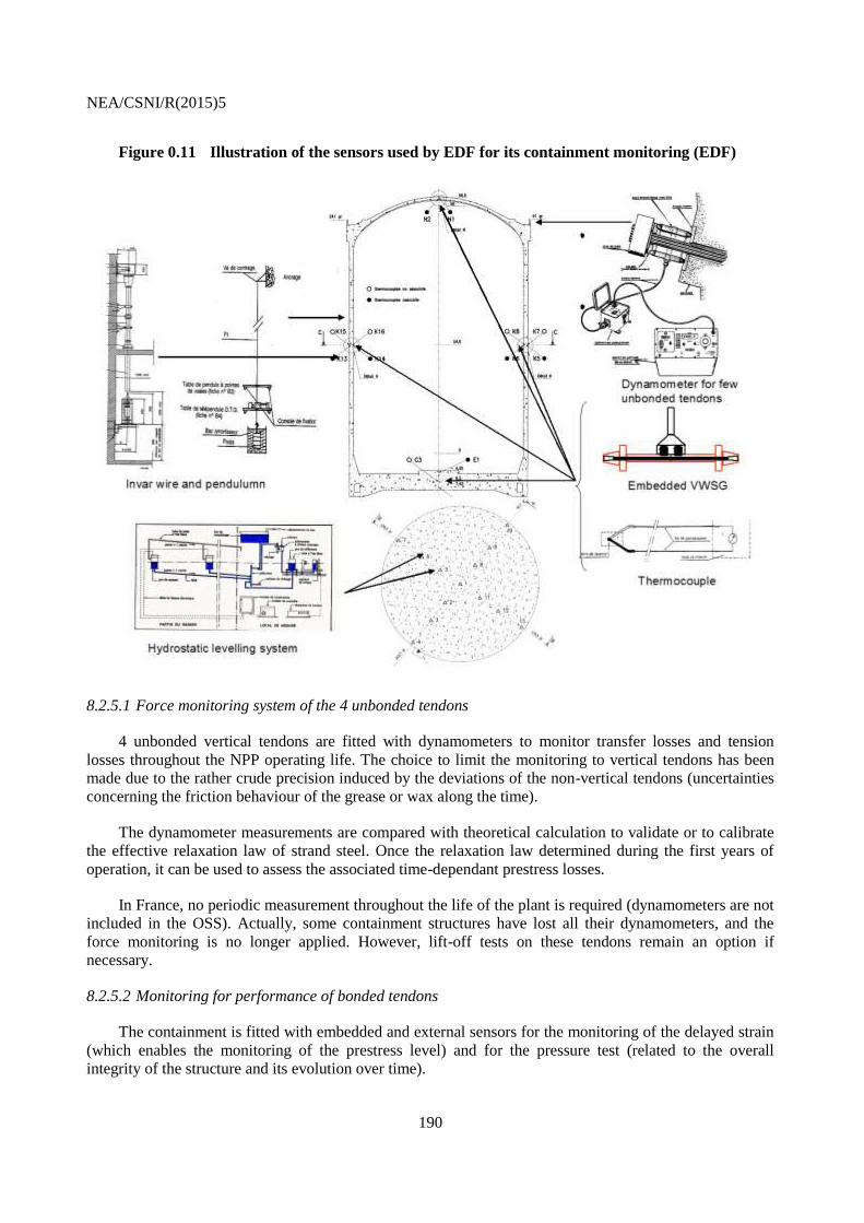
NEA/CSNI/R(2015)5
190
Figure 0.11 Illustration of the sensors used by EDF for its containment monitoring (EDF)
8.2.5.1 Force monitoring system of the 4 unbonded tendons
4 unbonded vertical tendons are fitted with dynamometers to monitor transfer losses and tension
losses throughout the NPP operating life. The choice to limit the monitoring to vertical tendons has been
made due to the rather crude precision induced by the deviations of the non-vertical tendons (uncertainties
concerning the friction behaviour of the grease or wax along the time).
The dynamometer measurements are compared with theoretical calculation to validate or to calibrate
the effective relaxation law of strand steel. Once the relaxation law determined during the first years of
operation, it can be used to assess the associated time-dependant prestress losses.
In France, no periodic measurement throughout the life of the plant is required (dynamometers are not
included in the OSS). Actually, some containment structures have lost all their dynamometers, and the
force monitoring is no longer applied. However, lift-off tests on these tendons remain an option if
necessary.
8.2.5.2 Monitoring for performance of bonded tendons
The containment is fitted with embedded and external sensors for the monitoring of the delayed strain
(which enables the monitoring of the prestress level) and for the pressure test (related to the overall
integrity of the structure and its evolution over time).

NEA/CSNI/R(2015)5
191
The layout of the sensors is driven by some basic principles: adequate instrumentation performance,
robustness, redundancy, diversity of techniques, ability to interpret the measurement in term of structural
behaviour. From a metrological point of view, it would be required to be able to check and calibrate
periodically all the sensors. For embedded sensors, accurate calibration is no longer possible, of course.
But long term experiments have been undertaken in controlled conditions to determine the possible
instrumental drift or other uncertainties sources for the VWSG embedded in containment concrete.
EDF takes advantage of the standardization of its nuclear fleet for the monitoring system as well. A
“first-of-a-kind” containment may include about 400 to 500 embedded sensors, the subsequent plants
requiring fewer devices, due to the acquired feedback from the prototype. To fully benefit from feedback, a
similar layout of the sensors applies among the different plants of a given series of plant.
The sensors are strategically placed within the structure:
In areas where the expected behaviour is representative of the overall response of the
containment and where the interpretation of measurements is relatively simple (mid-height of the
cylinder, centre of dome);
In areas where some tensions can occurs due to bending induced by pressure (gusset, cylinder-
dome junction, near the large penetrations, etc.).
If needed for dedicated analysis, other sensors can be added, such as inclinometers to monitor the
structure rotations in the areas which can undergo significant bending (gusset, dome ring girder). The
displacement between the flange of the equipment hatch and the surround concrete has also been measured
during pressure test in specific plant, where data were needed to feed numerical analysis or to assess the
effectiveness of maintenance operation (bolt replacement, for example).
An example of possible layout for pendulums, invar wires, dynamometers, VWSG, thermometers and
levelling pots for a standard case is shown in

NEA/CSNI/R(2015)5
192
Figure 0.12 below.

NEA/CSNI/R(2015)5
193
Figure 0.12 Example of a typical monitoring system used by EDF (sensors installed around
penetrations are not represented)
Table 0.3 below provides a list of the devices used for containment monitoring, with their specifications
and locations.

NEA/CSNI/R(2015)5
194
Table 0.3 Example of specifications for sensors included in EPR Flamanville 3 containment.
Sensor Monitored zone Number Property measured Comments
Dynamometers tendons injected with grease
4 Cable tension Vibrating wire technology (Telemac or Geoinstrumentation)
Embedded strain gauges
Foundation raft 30 Local strains VWSG (Telemac C110)
Sensitivity = 0.35 μm/m
Range = 2900 μm/m Gusset plate 72
Cylinder wall 114
Ring belt 30
Dome 39
Equipment hatch 12
Vertical invar wires Cylinder wall 3 Vertical deformation Placed on 3 vertical axes:
Pendulums Cylinder wall 9 Vertical displacement Placed on 3 vertical axes
Levelling pots Foundation raft 17 Settlement Water level type.
2 * 9 pots on the diameters 20°-200° and 60°-240° corresponding to the radii: 23m, 20m, 12m, 3m and the centre.
Temperature sensors Coupled with levelling pots (foundation raft)
17 Temperature PT100 probe
Foundation raft 10
Gusset plate 24
Cylinder wall 55
Ring belt 15
Dome 20
Equipment hatch 6
The rate of failure encountered on EDF containment is about 1% per year for the embedded VWSG,
and less for the temperature probes. In some cases, advanced measurement methods enable to recover
weak or disturbed signals from the sensors [56] and [55]. When it is no longer possible to retrieve
measurement from embedded sensors, EDF has defined a suited instrumentation dedicated to the long term
monitoring of the containment, called in French “Dispositif d’Auscultation Optimal” (DAO) or “Optimal
Surveillance System” (OSS). The OSS shall be maintained throughout the life of the structure. It includes
on one hand the sensors which deliver global displacement and which can be replaced (such as pendulum)
and, on the other hand, the sensors dedicated to local phenomena, initially embedded in concrete (such as
VWSG) and thus inaccessible (see Table 0.4). An equivalent system is then required to maintain the OSS
in case of failure of an embedded sensor. For that purpose EDF has developed new devices.
The OSS includes the following embedded sensors:

NEA/CSNI/R(2015)5
195
2 vertical and 2 hoop strain gages located at mid-height of the cylinder. To get a rather simple
interpretation and evaluation of the results, the instrument is located at sections away from
structural discontinuities (hatch, buttress, etc.);
2 strain gages at the centre of the dome, in two horizontal perpendicular directions;
1 vertical strain gage in the gusset (thick junction between raft and cylinder), available at least on
one plant of a site.
Table 0.4 Sensors included in the OSS of the EDF’s NPP fleet.
Quantity Original monitoring instruments
Part of the OSS Replaceable nature of the equipment
Displacement Survey markers YES YES
Displacement Plumb lines and Invar wires YES YES
Strain Vibratory strain meters embedded in the concrete
YES NO
Temperature Thermocouples YES YES
A maintenance plan is carried out throughout the operating life of the plant. The systems that can be
inspected (such as pendulum or Invar wire, but also data logger and cabling) are regularly checked and
calibrated with specific procedures by experienced technicians, with significant skill in measurement
devices. The usual period for calibration is one year for any measurement device, but thanks to the
feedback gained over the hardware and the sensors, the periodicity has been extended up to 4 years.
For normal operation period, the standard frequency of acquisition ranges from 15 days to 3 months,
depending on the acquisition system and on the rate of observed deformations. During pressure tests, the
data measurements can be performed every hour, with mandatory stages (baseline before inflating or
beginning and end of pressure plateaus, for example).
The acquired data are collected by specialist technical team, which is in charge to check the validity
of the measurement, from a metrological point of view and by comparing the new records with the overall
trend of the time history curves. If a reading is considered as an outlier, a new measurement process is
launched. If the reading is accepted from a metrological point of view but denotes an unexpected behaviour
of the structure, it gives rise to an alert, and further analysis and/or monitoring are undertaken to better
understand the observed phenomenon and to assess the impact on safety.
Whatever the behaviour of the containment, a monitoring report is issue every two to five years,
depending on the observed strain rate. The purpose is to propose an overview of the behaviour, to check if
the observed deformation and temperature are consistent with the prediction and to state a structural health
diagnosis.
For the data processing relative to strain or displacement, the measured temperatures are used to remove
the effect of thermal dilation (seasonal variation for example) from the measured total strains. The
following figures (Figure 0.13 and

NEA/CSNI/R(2015)5
196
Figure 0.14) provide an illustration of the thermal effect on strain measurement and on the
subsequent data processing by the temperature records.
Figure 0.13 Example of concrete strain time history, with raw data affected by seasonal effects
– vertical strain in blue, hoop strain in red (EDF)
Typical results of measurement during the life of structure
before thermal correction
-1200
-1000
-800
-600
-400
-200
0
200
400
1/1/92 31/12/93 1/1/96 31/12/97 1/1/00 31/12/01 1/1/04 31/12/05
str
ain
s (
µm
/m)
( µm
/m)

NEA/CSNI/R(2015)5
197
Figure 0.14 Same data as Figure 0.13, after data processing– vertical strain in blue colour,
hoop strain in red colour (EDF)
To go further in the data analysis, it is necessary to use models, from simple equations to more
complexes structural models (FEM), in order to assess the theoretical behaviour. The comparison between
modelling results and monitoring data aims at determining some parameters, such as concrete stiffness
(Young modulus), or at predicting the evolution of delayed strain until the end of the operation time. The
consistency between previous model predictions and updated monitoring data is checked regularly,
typically when a monitoring report is issued.
During pressure test, linearity and reversibility of the strain curve against pressure shall be checked in the
tension zones (typically, mid height of the cylinder or centre of the dome). Sometimes, due to short term
creep of concrete, the reversibility criterion is not met just after the come back to the normal pressure but
some hours or days later (see examples in
Typical results of measurement during the life of structure
-1200
-1000
-800
-600
-400
-200
0
200
400
1/1/92 31/12/93 1/1/96 31/12/97 1/1/00 31/12/01 1/1/04 31/12/05
co
rrecte
d s
train
s (
µm
/m)
(µm
/m)
Prestressing phase
Delayed and thermal volumetric strains
Pressure tests
Pressure tests

NEA/CSNI/R(2015)5
198
Figure 0.15). In some areas of the containment, where bending and tension can occur during pressure
tests, non-linear strain curves may be observed, but, in most cases, the phenomenon is reversible and the
cracks openings are limited (see Figure 0.16 for an illustration).

NEA/CSNI/R(2015)5
199
Figure 0.15 Typical strain-pressure curve observed during a containment pressure test at mid
height of the cylinder
Figure 0.16 Synthetic example of strain-pressure curve during test, with a reversible non-linear
behaviour
The possible variations of local strains over the different tests are assessed to lead to an overall
diagnosis.
8.2.5.3 Visual inspection
Just before a pressure test, an overall examination of the surface of the containment is undertaken with
respect to cracks and defects. At peak pressure stage, visual inspections will focus on the most critical
areas, with monitoring of the longest (longer than 1 meter), widest cracks (wider than 0.3 millimetres), and
detection and mapping of any significant defect (spalling, delaminations, etc.). After completion of the test,
a second examination is carried out, with special attention given to checking the propagation and closure of
cracks. Residual defects are mapped and recorded, to give a reference state for later tests.
Any unexpected observation will be reported to the Design Authority of the Operating Company and
to the Regulator, and further investigation and remedial actions will be taken as necessary. Further testing
may be required to check the effectiveness of any remedial actions.
In addition to the Periodic Tests, 5-year period visual examinations are also carried out to monitor
ageing of concrete (defects and cracks) and steel (corrosion of rebar). In these tests comparison is made
with results of previous visual inspections.

NEA/CSNI/R(2015)5
200
8.2.6 Further needs
Reliable and efficient system that would allow the direct measurement of the force of a bonded tendon
would be considered as a significant progress. Some research works are currently performed in this
direction [50].
Monitoring system that would allow an enhanced multiplexing capability would help to get a more
accurate overview of the containment behaviour. In this respect, distributed fibre optics is a rather
promising technique [49].
Shrinkage and creep of concrete, as well as rebar corrosion and alkali aggregate reaction are related to
water content variation in concrete. Moreover, evaluation of water content in concrete members used for
biological or radiological shield are needed for safety analysis of beyond design accidental conditions.
Further research for concrete water content monitoring can help for that purpose [45].
For crack monitoring and visual inspection, a valuable support could be provided by the use of
ultrasonic sensors, acoustic emission or digital image correlation.
Whatever the novel techniques, it is recommended to assess it by the procedure proposed in [8].
8.2.7 Conclusions and recommendations
Although, direct monitoring of the bonded post-tensioning system is currently not possible, proven
reliable indirect methods can be used to ensure continuous integrity of the post-tensioning system over the
service life of the plant.
Preferably embedded or otherwise attached (retrofitted) instrumentation should be used to monitor the
response of the concrete containment structure to external loads (i.e. pressure loads during PPT and ILRT).
Where possible, a few tendons should be left unbonded to allow for direct monitoring of prestressing force.
For new structures, data collection should start during construction (at least at the beginning of the
tensioning of the cables) so that the initial state, i.e. baseline parameters could be established at the end of
the construction period.
Instrumentation should be proven, calibrated and reliable and should have sufficient redundancy.
Instrumentation should be of sufficient accuracy to be able to identify failure of small enough number
of strands so that the integrity of the concrete containment structure is not compromised.
Instrumentation should be strategically located in the areas of high stresses and deformations; location
of instrumentation should allow for easy comparison with the theoretically estimated values.
Care should be taken when interpreting the results of the monitoring. Response of the structure to
environmental and operating conditions (e.g. temperature, humidity) as well as volumetric changes in
concrete and long term relaxation of the post-tensioning tendons in the given environment should be well
understood in order to confirm design assumptions and ensure that prestressing force losses are within
acceptance limits and sufficient margins are maintained at all times during service life of the plant. If
necessary, structural analysis should be updated with actual ambient conditions and material properties.
The methods of testing the beams cast during construction of the containment structure can be used to
ensure integrity of the post-tensioning system; however, limitations of this method should be well

NEA/CSNI/R(2015)5
201
understood and considered. It is recommended to use this method in conjunction with monitoring
instrumentation method and visual inspection.
Visual inspection of accessible areas of concrete containment structure should focus on critical areas,
such as, for example anchorage regions, construction joints, areas of stress concentration as well as those
areas where leakage is detected during ILRT.
It is recommended to encourage and support any R&D effort to develop new devices that are able to
measure directly prestressing force in bonded tendon.
8.3 GSS technology
To this day, international standards do not propose an ISI program specifically adapted to GSS
tendons. The available documents only include prestressed containments with tendons injected with grease
or wax (ASME section XI, RG 1.35, etc.) for which local measurements of the tension in tendons are
generally carried out, and prestressed containments with bonded tendons (ETC-C, RG 1.90, etc.) for which
a follow-up program on overall behaviour of the structure is generally carried out.
Therefore, the purpose of this document is to present guide lines allowing the definition of an ISI
program for a containment consistent with GSS tendons specifications, and thus ensure the structure's
durability over of its operation time.
The recommendations presented in this document can be applied to a containment prestressed entirely
or partially with GSS tendons, with a torospheric or hemispheric dome (proposal not yet implemented).
8.3.1 GSS tendon specifications - Inspection principles
An ISI program of a prestressed containment with GSS tendons must allow:
The analysis of the evolution of the structure's mechanical behaviour in relationship with the
main phenomena of ageing (shrinkage, creep and relaxation) during its operation time,
To carry out an extrapolation of the containment's behaviour at the end of its operation time, in
order to plan, if needed, an adapted maintenance process (tendons retensioning operation, for
example),
To check the presence of specific pathologies (corrosion, cracking, delayed ettringite formation
(DEF), alkali aggregate reaction (AAR...) and deterioration.
The evolution of the containment's mechanical behaviour during its operation time is directly linked
to prestressing losses induced by the shrinkage and creep of the concrete and the relaxation of tendons.
These phenomena are taken into consideration during the design stage, and are taken into account during
prestressing design (determination of the unit capabilities and tendons spacing). However, as GSS tendons
are unbonded, they can be retensioned. Thus, in the event of shrinkage or creep higher than the values
considered during design (a typical concrete behaviour) and relaxation of tendon, a retensioning operation
can be planned. Thus, the containment is not critical in terms of the plant unit's operation time.
In terms of corrosion risk, which can lead to ruptures of wires or strands, GSS tendons have particular
features that render them less sensitive to these phenomena. GSS tendons benefit from more effective
protection from corrosion than tendons injected with grease, wax, or cement grout. GSS tendons have the
particular feature of being composed of greased strands individually sheathed at the manufacturing stage
by a layer of extruded high density polyethylene (HDPE). All strands are then gathered into a general duct

NEA/CSNI/R(2015)5
202
made of thick HDPE or steel, which totally isolates them from the environment. Thus, their protection
from corrosion comes from both the individual HDPE sheath and the grease as well as the injection of
cement grout in the general duct providing a sealed barrier completely surrounding the peripheral surfaces
of the individual sheaths. This protection is provided starting from the manufacturing of the strands until
the implementation on the site, then during the entire operational phase of the structure.
However the GSS prestressing system presents an area not better protected against the corrosion risk
than the other prestressing system: the anchorages and tendons excess lengths have to be protected with a
means of protection appropriate and sustainable.
Generally, the pathologies associated with problematic corrosion of tendons are induced by:
Poor storage conditions during the construction phase (tendons injected with grease, wax, or
cement grout),
Migration of grease during the operation time (tendons injected with grease).
However, concerning GSS tendons:
Strands are not directly in contact with the environment during storage and threading phases
(protection provided by grease and individual sheath).
During the operation stage, the general duct injected with cement grout and the individual strand
protection, provides total isolation from the environment.
The tendon ends (excess length) are protected by a long cap injected with grease or wax, offering
protection comparable to tendons injected with grease or wax. Therefore, all caps can be
inspected during the overall operating life of the plant unit.
Note that the phenomena of stress corrosion, not dealt with here, which mainly depends on the grade
of steel provided, is mainly independent of the selected technology.
8.3.2 Proposal of an In-Service Inspection (ISI) program
8.3.2.1 Direct measurement of prestressing force
Two main ways can be used in order to perform the direct measurement of the prestressing force. The
measurement is either directly measured at reference tendons equipped with dynamometers (load cells) or
other measured by lift-off in order to:
Measure the relaxation of tendons and isolate the part attributable to creep and shrinkage,
Verify consistency between measured prestressing losses and design hypotheses.
Note that the purpose of a lift-off is to verify the force of a tendon after it has been stressed. This test may
be conducted with a hydraulic stressing jack by lifting the anchor head off the bearing plate to determine
the residual effective force in the tendon at the anchorage (see

NEA/CSNI/R(2015)5
203
Figure 0.17 for an example of a force/displacement curve obtained during a lift-off test).

NEA/CSNI/R(2015)5
204
Figure 0.17 Example of a force/displacement curve obtained during a lift-off test
In order to limit any measurement disturbances induced by friction, it is preferable to consider non-
deviated GSS tendons (ducting not affected by a close penetration) as reference tendons. Based on RG
1.90, it is recommended to consider reference tendons for each group (depending on the design):
3 pure vertical tendons,
3 horizontal tendons,
3 dome tendons,
4 gamma tendons,
3 inverted U tendons (hemispheric dome).
If the measurement of force in the reference tendons is performed by lift-off or equivalent test,
sufficient precautions must be taken in order to guarantee that these tension measurement operations are
not detrimental to the tendons. Therefore, it is preferable to carry out lift-off operations of complete blocks
(threaded blocks) with a dedicated annular jack in order to limit block displacement, necessary for the
measurement.
Lift-off test frequency is to be determined depending on the prestressing systems implemented as well
as the available experience feedback. Prior qualification tests on models can also be performed.
For the site's first plant unit, it is recommended to equip at least 4 vertical tendons (or inverted U
tendons) for the Initial Structural Integrity Test (ISIT). This provision allows for regular follow-up of the
relaxation phenomenon, for at least the first three years of operation in order to have an ample database on
the deferred behaviour of GSS tendons.
If the structure considered is prestressed with both, GSS tendons and tendons injected with cement
grout and it lacks non-deviated vertical GSS tendons able to be measured, only 4 vertical tendons (or
inverted U tendons) should be left ungrouted so that it could be equipped with dynamometers. The ducts
for these tendons shall be filled with grease in order to limit the number of tendons with different
prestressing technologies in the structure.
NEA/CSNI/R(2015)5
205
8.3.2.2 Overall monitoring of the containment's behaviour
A monitoring system of the containment must be implemented in order to analyse the evolution of the
overall behaviour of the structure in operation stage and during tests.
The monitoring device will be composed of a redundant and diversified instrumentation in order to
allow:
Verifying the containment's behaviour is consistent in comparison with the design hypotheses,
Verifying the evolution in the containment's behaviour over time, in operation (evolution of
deferred deformations, localised deformations) and during the tests (module evolution, localised
deformations, linear and reversible behaviour).
Thus, the monitoring system will consist at least of:
Pendulums (variation in diameter, inclination)
Invar wires (elongation, overall deformations),
A sufficient number of extensometers and thermocouples placed in specific points of the
containment, far from discontinuity areas (in the cylinder wall and in the dome).
The measurements and interpretations are carried out with an appropriate frequency that can evolve
with time, depending on the kinetics of the phenomena to study during the operation time. Based on RG
1.90 (alternative A), it is recommended to perform a measurement every 2 months until the first test, then
every 6 months after. In the case of specific needs, this frequency can be increased.
All of the sensors included in the monitoring system, necessary and sufficient to optimally follow-up
on the structure's behaviour during its entire operating life and to produce any necessary justifications,
must be defined. The functionality of the whole reduced number of sensors included in the optimal
monitoring system (called “OSS”, in ETC-C- Part 3) must be ensured during the structure's entire
operating life (cf. §”Monitoring for performance of bonded tendons”). Additional sensors can be added to
follow the structure's behaviour at a young age. However, the loss of sensors will not have an impact on the
follow-up of the structure's behaviour. Therefore, they won't necessarily be replaced, contrary to the
sensors included in the optimal monitoring system. These will need to be installed by verifying, as much as
possible, the redundancy and diversification of measurement means.
Thus, in the case of inoperative embedded extensometers, included in the OSS, during the structure's
operating life, they can be replaced by surface mounted extensometers, commonly used for substitution.
8.3.2.3 Tests
This document does not deal with test cases (independent of the type of prestressing technology)
which must be carried out frequently and at a sufficient pressure level. During the pressure tests, the
mechanical behaviour of the containment will be analysed based on a reinforced monitoring system (cf.
§0).

NEA/CSNI/R(2015)5
206
8.3.2.4 Visual examinations
Visual examinations must be regularly performed on the containment's surface (regular and specific
areas) and prestressing anchors (caps and tendon heads).
Periodical visual examinations of the containment surface must be performed (during operation
and pressure tests) in order to detect any deteriorations of the concrete (flaking, cracking) in the
common area. The most critical areas will also be inspected, particularly, the specific areas or
those under important solicitation, such as the areas near the prestressing anchors or the main
deviations (near air locks, ribs).
Periodical visual examinations of the prestressing anchor caps must be performed in order to
detect any pathology such as abnormal caps deformations, grease leaks, corrosion or other
deteriorations.
In this event, a few caps will be removed in order to inspect the anchor head and also to verify the
lack of corrosion marks, abnormal ageing or other deteriorations. The tendon samples subject to cap
removal will have a minimum of 4 caps per group of tendons, based on rules of RG 1.35, ASME section
XI IWL, concerning random selection of tendons to inspect. Thus, all the prestressing anchors must remain
accessible during the plant unit's entire operating life.
The frequency of visual inspections could be carried out 1, 3 and 5 years after the ISIT, then every 5
years (based on RG 1.35).
In the field of bridges industry, GSS tendons are often used for internal or external prestressing.
Inspection programs are defined to check the integrity of the prestressing system. The main practices
implemented are:
Measurement of the prestressing force with load cells set in anchorage blocs or using
magnetostrictive sensors,
Direct measurement of the strands stress by transversal pulling of the strand when the tendons are
accessible,
Lift off test,
Permanent acoustic monitoring on specific area,
X-ray or gamma-ray control to check the duct filling and detect strands failures,
Ultrasonic test to detect defects on strands near the measurement point,
Visual examination of the anchorages areas.
8.3.3 Assessment and outlook
This document provides elements which define an in-service inspection program for a prestressed
containment with GSS tendons, based on the adaptation of principles described in the ASME section XI,
RG 1.35, RG 1.90 and ETC-C. Thus, alternatives are proposed in order to avoid requiring operations
inappropriate for GSS tendons such as:

NEA/CSNI/R(2015)5
207
To require to remove entirely a tendon. Pulling out the strands of the wedges, necessary to carry
out this operation, can induce significant excess stress in the tendon (low tension losses of GSS),
which could lead to limit the initial tension (penalising for the design) or to change the whole
tendon (penalising for the operation). In addition, protection against corrosion of the strands
which have been re-threaded can be not as efficient as before, because the grease might be less
well spread along the strand than in the initial situation (operation carried out in the factory
during the manufacturing stage).
To carry out lift-off operations with pulling out the strands of the wedges. It can induce excess
tension in the tendon, inaccuracies in force measurement, initiate strand rupture in the case of a
wedge tightening in an area near the initial position. Therefore, this operation is to be avoided to
measure tendon force. However lift-off operations of complete threaded blocks can be carried out
without impact on the design.
To carry out stress measurements directly on the strands. This seems to present difficulties in
terms of setting up sensors and durability.
The elements proposed in this document fitted to containments with GSS tendons, are based rather on
the requirements for containments prestressed with bonded tendons than unbonded. If a sufficient level of
knowledge is reached on the GSS prestressing system and on non-destructive inspection means, allowing
individual integrity check of the tendons, an alternative could be proposed based on inspection procedures
habitually implemented for unbonded tendons. This would require testing and mock-up in order to validate
the consistency and representativeness of results obtained as well as the lack of detrimental consequences
for the tendons. This alternative could also be applied by using prestressed test beams stored in
environmental conditions to best duplicate that the containment structure in order to test the evolution of
the mechanical characteristics (concrete and tendons) and to check the ageing phenomenon.
To this day, an overall monitoring of the structure rather than a direct inspection of the prestressing
seems to be the best compromise.

NEA/CSNI/R(2015)5
208
9. IN-SERVICE INSPECTION; CZECH EXPERIENCE
9.1 Check of cables prestressing
Checks of prestressing are implemented by regular round measuring, when the connector of
tensometric sensors is connected to the connector of the measuring system and the tests is started.
Measuring is implemented regularly once in a month. Thus, every drag anchor is measured individually.
Cables of cylinder and cables of the dome are measured. Measuring on the cables of the dome is carried
out by the worker, who is in a cage lifted by the handling crane. Thus, every tensometric place is measured.
In case it is not possible to use the handling crate, there is a worker with climbing certification and
equipment, who is ready to rope down from the dome to each place measured. The data obtained and
measured are saved and recorded. The proper evaluation is carried out on computer.
For this purpose a one-purpose measuring system has been designed and produced. It serves only for
round checking of prestress.
The source of literature for this chapter is the Report on advanced tendons prestress measurement
systems, No. 201200766 [41].
9.1.1 Check of cables functionality
Checks of the wider scope, i.e. above the scope of the planned operating checks of prestressing cables,
were carried out on two cables, including the tests for assessment of their residual life. Checks of
functionality of cables were solved and carried out within implementation of the change of the cables
1.80S and 1.35K in 2009. When the original cable, which was installed approx. 16 years ago, was taken
out, the condition of the surface for presence of the corrosion and the places with possible occurrence of
corrosion in the nearest years were monitored. Further, the condition of the preservation layer along the
entire length of the cable was monitored. Places affected with corrosion and places with disrupted and
degraded preservation layer were ascertained during this monitoring process. After this situation was
ascertained, samples were taken from the cables - from the bends of the cables, i.e. bends with eye rings
and with 15 metres of wires. These segments were left for performance of tests.
After the performance of tests were suggested and agreed by the operator - NPP Temelin - both ends
of the cables were tested in 2010/2011 in the Test and verification training stend in the premises of ÚJV
Řež, a. s. (Nuclear Research Institute).
9.1.2 Calibration of tensometric measuring of prestress
Calibration of tensometric measuring is always performed when a significant deviation of the values
measured is ascertained. However, the proper performance is preceded by assessment of the cause. The
most frequent cause of this situation is the malfunction of the measuring elements - tensometric measuring
or cable output. If the malfunction ascertained is caused by the tensometric measuring elements, they are
always reinstalled.
The tensioning set is then used by means of which the real value of force of prestressing in cable is
ascertained. This moment - the point of the prestressing force - is ascertained by means of the nut position
sensors. The force is measured in the moment of separation of the nut from the washer, or separation of the
nut together with the washer. The point of separation is monitored on the control computer display. The
measured force is then assigned to the tensometric measuring so that the measuring of prestress of the
anchor equipment shows the right value of prestress.

NEA/CSNI/R(2015)5
209
Figure 0.1 Nut position sensors at the calibration of the tensometric measuring
9.2 Check of cables condition
9.2.1 Visual check of cables prestressing
Visual check of prestress of cables lies in check of integrity of the covers of drag anchors. Any defect
of these covers could indicate defect of the cable. The check of dome cables is carried out by means of
binoculars. All the covers are viewed from the area of concrete lining (so that it is not necessary to erect
scaffolding). Check of wall cables is already carried out as a round check. Any non-standard situation
ascertained is solved in detail. The protective cover of the drag anchor is removed and the condition is
examined.
9.2.2 Taking samples of preservative grease
The grease prescribed and used as the anticorrosive protection of prestressing cables of the
containment in the operating documentation is the grease used for arms and declared as “grease gun“. In
accordance with the Russian standard GOST 19537-83 [26], based on which the below (see Table 0.1)
specified quality certificates are issued and characteristics are prescribed.

NEA/CSNI/R(2015)5
210
Table 0.1 Analysing the preservative grease.
Indicator Value Testing methods
1 Appearance Homogeneous yellow up to brown colour
Paragraph. 4.2 [26]
2 Dripping point min. 60°C GOST 6793
3 Softening temperature min. 50°C GOST 6037 p. 4.3
4 Impacts of corrosion on metal fulfilled GOST 9.080 p. 4.4
5 Acidity number 0.50 to 1.00 GOST 5985 p. 4.5
6 Content of water no GOST 2477
7 Content of mechanical dirt not more than 0.07 hm% GOST 6370 p. 4.7
8 Content of acids and alkalis Slightly acidic GOST 6307 p. 4.7
9 Test of protective properties fulfilled GOST 9.054 (method 1)
10 Penetration 90 to 150 mm-1 GOST 5346 (method B)
Sampling of the preservative grease from the surface of the eye ring is carried out (once a year) on the
group of cables selected in advance. Part of the protective layer of the anchor equipment is taken for the
purpose of analyses at which the ability to provide reliably the protective function is ascertained. The
analysis is carried out in the process control laboratory of NPP Temelin. In case it is ascertained that the
sample already doesn't correspond to the properties required, a work order is issued for implementation of
renewal of preservation. Methods of performance of repairs are specified in chapter 0.
9.2.3 Analyses of the preservative grease and repairs of preservation
9.2.3.1 Analyses of the preservative grease
Analyses of the preservative grease may be divided into three parts according to the place where the
grease is found. One sample is taken from the anchor equipment, one sample is taken from the preservative
bath, and one sample is taken from the new grease from cans.
Analyses of the samples from the anchor equipment are carried out in accordance with the NPP
internal procedures and are performed in the process control laboratory of Temelin power plant. Other
analyses are implemented irregularly.
Based on the checks of the exposed cables taken out (1.80S and 1.35K) it is evident that the corrosion
damage of individual wires was caused always in places of cable bends on the eye rings of drag anchors.
The reason is probably the highest intensity of condensation of air humidity at changes of open-air
temperature and humidity just in these localities. Closing of metal covers of drag anchors significantly
extends the time of humidification of the cables and increases corrosion risks.
To ascertain, whether the properties of the preservative grease in the bath and of the new grease in
cans provide sufficient protection, it is necessary to take the samples which will be subject to analyses. The
analyses will be carried out in two workplaces, i.e. in the process control laboratory of the power plant and
in the accredited laboratory in the Ukraine. The process control laboratory will carry out the tests which
will determine, whether the grease meets the requirements or not. The accredited laboratory in Ukraine will
examine the samples in accordance with the original and still valid standard GOST, based on which the
grease was supplied years ago. Thus, it will be ascertained whether it meets the properties declared or not.

NEA/CSNI/R(2015)5
211
Sets of samples were taken for the purpose of analyses. They were two sets by four samples (0.2
litres).
The samples from the preservative bath were taken when the temperature of the hot bath was 70°C.
The sampling was carried out:
From the preservative bath - from the surface;
From the preservative bath - from the bottom;
From the store of grease – from 20 L can;
From the store of grease – from 200 L barrel.
9.2.3.2 Results of the samples from the anchor equipment
The laboratory of the Temelin power plant uses spectrometry in infra-red area of wave lengths - the
technology of attenuated absolute reflection - for the purpose of evaluation of the quality of preservative
grease. Based on the spectra measured it is possible to ascertain presence of absorption belts pertaining to
the types of chemical compounds occurring thanks to the oxidative degradation of hydrocarbons (wave
numbers approximately 1700 (1660-1800) and 1150 cm-1
); then it is possible to assess the rate of the
degradation according to the intensity of the absorption belt.
Presence of water is determined by means of absorption belts - OH groups in the area of the
approximate wave number of 3400 cm-1
.
The samples of the preservative grease from the cables of the prestressing system of the containment
supplied for the purpose of check to the laboratory often contain significant lack of homogeneity. That is,
only a small surface layer is degraded in many cases, in which also the increased content of water is
ascertained. It is probably the cause of the degradation. In some cases there are also small solid particles of
dirt. However, the grease is usually in good condition under this surface layer showing no significant
indications of degradation and without content of humidity or dirt. Quantification of e.g. content of water
for the whole sample delivered has no sense. The same applies also for quantitative determination of solid
particles of dirt. If any dirt is present in the grease, their occurrence is determined by smearing the sample
on the crystal using the technology of attenuated absolute reflection, the principle of which is simple or
multiple absolute reflection of radiation on the phase interface of the measured sample and the measuring
crystal with sufficiently high index refraction.
Routine infrared of the spectroscopic analysis carried out by the laboratory of the Temelin power
plant showed good condition of the grease in warehouse stock. The grease in the preservation bath showed
traces of oxidation degradation products, but it will be necessary to examine their extent by a complex
analysis carried out in accordance with GOST 19537-83 [26].
Taking into account the small quantity of samples the laboratory is not able to carry out the tests of
physical parameters.
9.2.3.3 Results of the samples from the preservative bath and from cans
Within the assessment the analyses of the following samples were carried out:
Sample no. 1 – grease from the surface of the preservative bath
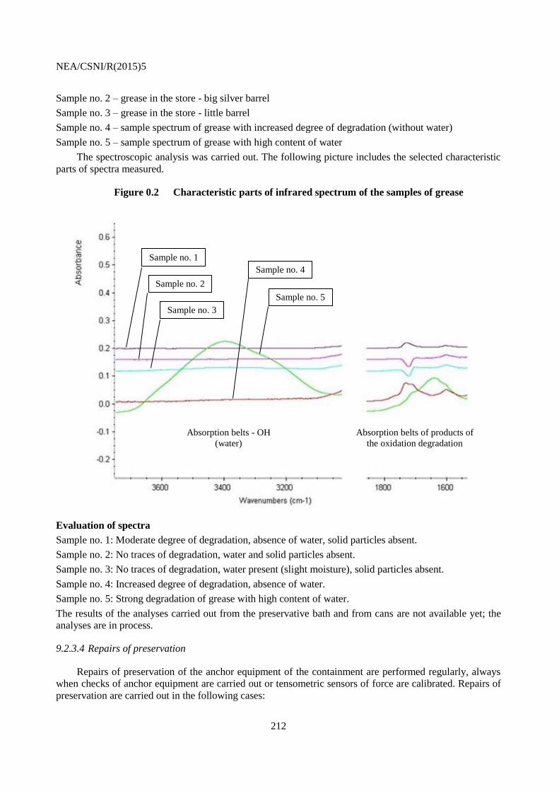
NEA/CSNI/R(2015)5
212
Sample no. 2 – grease in the store - big silver barrel
Sample no. 3 – grease in the store - little barrel
Sample no. 4 – sample spectrum of grease with increased degree of degradation (without water)
Sample no. 5 – sample spectrum of grease with high content of water
The spectroscopic analysis was carried out. The following picture includes the selected characteristic
parts of spectra measured.
Figure 0.2 Characteristic parts of infrared spectrum of the samples of grease
Evaluation of spectra
Sample no. 1: Moderate degree of degradation, absence of water, solid particles absent.
Sample no. 2: No traces of degradation, water and solid particles absent.
Sample no. 3: No traces of degradation, water present (slight moisture), solid particles absent.
Sample no. 4: Increased degree of degradation, absence of water.
Sample no. 5: Strong degradation of grease with high content of water.
The results of the analyses carried out from the preservative bath and from cans are not available yet; the
analyses are in process.
9.2.3.4 Repairs of preservation
Repairs of preservation of the anchor equipment of the containment are performed regularly, always
when checks of anchor equipment are carried out or tensometric sensors of force are calibrated. Repairs of
preservation are carried out in the following cases:
Absorption belts - OH
(water)
Absorption belts of products of
the oxidation degradation
Sample no. 1
Sample no. 2
Sample no. 3
Sample no. 4
Sample no. 5
NEA/CSNI/R(2015)5
213
Damage of preservation layer of anchor equipment;
If degradation of preservation layer is ascertained.
In the first case, only the damaged place is repaired by warming up the grease in a vessel and its
application on the surface preserved using a brush. In the second case, it is necessary to remove the
degraded layer using a plastic spatula, mostly as far as to the metal. Then, new grease is warmed up and it
is applied on the surface preserved using a brush. For application it is recommended to warm up the parts
by hot air, so that the new preservation layer mingles with the layer on the surface.
9.3 Tests of strain-gauge measuring systems
Tests of tensometric measuring systems were carried out so that tensometric sensors were installed on
the bolt of the drag anchor installed in the stend. Depending on the tested tensometric sensors also the
scope of load tests was proposed – standard, temperature tests (temperature tests -30 to +60°C in the area
around the drag anchor). The first tests were carried out on all tested variants. The second tests were
carried out only on two selected.
9.3.1 Summary of the requirements for sensors measuring the prestressing force
a) Requirements regarding utilization of measured values:
- Measuring of sensor in the scope of force in the cable from 0 to 12MN;
- Distinctiveness of measuring ±100kN;
- Accuracy of determination of the value of prestressing force ±200kN;
- The sensors must reliable measure during the whole period of life of the prestressing cable
(block).
b) Requirements regarding environment and conditions of action:
- Resistance against repeated changes of the force in the cable in the range from 0 to 10MN in
the minimum number 5 cycles ("big cycle");
- Resistance against cyclical changes of the force in the cable in the scope of ±100kN in the
order of 104 cycles (changes of stress caused by changes of the ambient temperature);
- Measuring in the scope of the temperatures from –30°C to +60°C;
- Measuring at the relative humidity from 10% to 100% with the option of surface
condensation;
- Functionality of the sensor for seismic events up to the level of the maximum calculating
earthquake.
c) Requirements regarding installation and operation of the measuring system:
- Installation and calibration without necessity to release prestress in the cable;
- Continuous renovation of sensors without the necessity to handle the prestressing cable.
9.3.2 Summary of the requirements for sensors proving functionality of the cable
a) Requirements regarding utilization of measured values:
- Measuring of sensor in the scope of force in the cable from 0 to 12MN;
- Guaranteed signalisation of change of prestressing force by more than 500kN;
- The sensors must reliable measure during the whole period of life of the prestressing cable
(block).

NEA/CSNI/R(2015)5
214
b) Requirements regarding environment and conditions of action:
- Resistance against cyclical changes of the force in the cable in the scope of ±100kN in the
order of 104 cycles (changes of stress caused by changes of the ambient temperature);
- Measuring in the scope of the temperatures from –30°C to +60°C;
- Measuring at the relative humidity from 10% to 100% with the option of surface
condensation;
- Functionality of the sensor for seismic events up to the level of the maximum calculating
earthquake.
c) Requirements regarding installation and operation of the measuring system:
- Installation and calibration without necessity to release prestress in the cable;
- Continuous renovation of sensors without the necessity to handle the prestressing cable.
9.4 Tests of the cables taken out
The tests created part of the technical aid of ÚJV Řež, a. s. within the project Creation and application
of the long-term strategy for stabilisation of the prestressing system of Temelin envelopes.
The goal of these tests was to perform a series of load tests of the cable taken out, evaluate the process
of these tests and take the determined sections of the cable tested for the purpose of subsequent analyses
and tests. The goal of the mentioned and the subsequent tests was the suggestion of technical and
organisational measures for minimisation of operational failures of prestressing cables of the containment.
The test starts in the moment of installation in the test stend.
9.4.1 Installation procedures
After the already tested sample of the cable with the length of 10m has been disassembled, the
auxiliary steel rope from 478 pcs of 5 mm diameter wires was pulled through the stend. The nuts of the
drag anchor were unscrewed to the maximum possible degree, so that the bolt of the drag anchor is inserted
in the stend as much as possible. The pulling clamp was attached to the cut end of the sample of the cable.
The pulling clamp was attached to the end of the rope pulled through. The cable was pulled through the
stend by means of the rope and the manual winch. In this phase the pulling bracket was installed.
Installation tapes were gradually removed during the installation of wires. After all wires had been
installed the wedge was installed, 2 pieces of hydraulic cylinders were assembled, and clamps were
attached. Wires of the cable were straightened by means of two linear hydraulic cylinders. The clamp was
tightened after all wires of the cable had been straightened.
The stressing device, which is placed on the movable undercarriage, was connected to the test stend.
Standard pushing device was used for connection, which interconnected the entire system with the eye
ring.
By subsequent slow drawing of individual pistons of the stressing gun out the cable was straightened
by gradual sitting down of the piston rod on the supporting platform of OSS. The maximum force in the
system not exceeding 0.1 MN is assumed there.

NEA/CSNI/R(2015)5
215
Figure 0.3 Fixed loose end of the cable
9.4.2 Load test procedure
The prestressing to the force of 9.5 MN was carried out gradually with the holding time of 5 minutes
at the values of 2 MN, 5 MN, 7.5 MN, and for 20 minutes with the force of 9 MN. The whole load
application was repeated 3 times. After the holding time on the 4th cycle of the third repeating the load was
applied on the test cable in another 10 cycles with the value of Fperzik = 9.2 MN and with the holding time of
5 minutes. The holding time between the individual cycles was 3 minutes. After 10 cycles were completed
the cable was stabilized on the force of 9 MN. The holding time of 5 minutes was before the last load
application to the value of Fmax = 9.5 MN.

NEA/CSNI/R(2015)5
216
Figure 0.4 The overview of the load cycles of the test procedure
9.4.3 Completion of the load test
After the series of the load cycles were performed the fastening clamp was dismantled, the tested
cable was released and taken out, and the condition of the cable was recorded focusing particularly on:
Burst wires in the eye ring bend;
Burst wires in the active length of the cable;
Depth of cuts and scratches in wires.
Samples were taken from the cable tested this way for the purpose of the subsequent analysis.

NEA/CSNI/R(2015)5
217
Figure 0.5 Draft of the sample taking of the eye ring segment
9.5 Tests of drag anchors and eye rings
The goal of the tests is performance of load tests of Drag anchors and Eye rings in accordance with
the work operation approved. The tests of the drag anchors were performed on the prestressing base of
Temelin nuclear power plant in the Test press ZK 12.5, where the 100% scope of tests was performed for
all tested drag anchors, including recording of the data in the plan of checks and tests with the attendance
of the authorized person. Each drag anchor went through the test assembly. Based on the tests successfully
performed the inspection report was issued.
9.5.1 Test procedure
Each drag anchor went through test assembly, successfully went through the Load test 1 – the load of
12.5MN was applied on the sets during the test (100% of the sets), through the Load test 2 – this test serves
for testing of connection of the drag anchor with the eye ring (by means of wedges), which must stand load
for tearing off with the force of 50 kN (10% of the sets), and disassembly with eye ring.
The drag anchor and the eye ring which met all the requirements, the compliance of which was
confirmed by PKZ (the plan of checks and tests), Final test, Inspection report, and Declaration on
conformity, shall be regarded as the set which complied with the test. The procedure of the Load tests no. 1
and no. 2 is the same as for eye rings testing.

NEA/CSNI/R(2015)5
218
Figure 0.6 Tests of sets of Drag anchor - Eye ring
Figure 0.7 Test of set of Eye ring - Drag anchor

NEA/CSNI/R(2015)5
219
9.6 Qualification of measuring systems (sensors of force)
The force sensors to be used for measuring on the prestressing tendon of the containment had to go
through vast tests first, which were performed on OSS, on Test press ZK 12.5, and on the Tensile machine
TS3. After the both phases of tests have been successfully performed, the third phase will be performed in
year 2012, during which concurrence of the current and the new measuring method will take place on the
selected ends of the cylinder cables of Temelin containment.
9.6.1 Requirements for newly installed sensors
a) Tests regarding utilization of measured values:
- Scope of measuring; its distinctiveness and accuracy;
- Impact of changes of the ambient temperature on measuring of the sensor - elimination of
the impact of changes of the ambient temperature on the value of the prestressing force
measured.
b) Tests regarding environment and conditions of action:
- Resistance against repeated changes of the force in the anchor as a result of easing of the
anchor;
- Resistance of the sensor against cyclical changes of the force in the anchor as a result of
changes of the ambient temperature;
- Resistance of the sensor against external impacts (humidity, changing temperature) and the
requirements for protection of the sensor against these impacts.
c) Tests regarding installation and operation of the measuring system:
- Determination and verification of the requirements for handling with the prestressing cable
at the installation of the sensor;
- Determination and examination of the requirements for installation of the sensors on already
prestressed cables in the construction (protection against weather, limiting conditions of
installation, time demandingness of installation, and handling with the cable during
installation);
- Examination of the ability of the sensor to measure changes of the force in the cable at the
failure of some measuring components of the sensor, possibilities of repairs of the sensor
without necessary calibration requiring handling with the prestressing cable;
- Life span of individual components of the sensor and requirements for maintenance and
continuous restoration of the sensor during operation of the system (intervals between the
replacement of the components, necessary maintenance, and calibration).
The tests and examinations performed for the individual types of sensors shall verify observance of
the requirements for new sensors. They are performed based on the data provided by the manufacturers of
individual components supplemented, as needed, by the tests of the entire sensor and its components. For
the tests of the entire sensor it is assumed that OSS and the test press ZK 12.5 will be used. They will allow
simulation of behaviour of the anchor of the prestressing cable with real placement of individual
components of the sensor. It is possible to test individual components of the sensor on individual devices
(e.g. fatigue tests and climatic impacts tests).
After the tests and examinations are completed in all areas for the selected types of sensors
determined for future installation on the construction, the certificates proving the fitness of the sensors to
perform the required function will be issued.
See Table 0.2 below for explanations of abbreviations and vocabulary used in this chapter.

NEA/CSNI/R(2015)5
220
Table 0.2 Specific abbreviations and vocabulary used in this chapter.
NPP Temelin Nuclear Power Plant Temelin
ÚJV Řež, a. s. ÚJV Řež, a. s., http://www.ujv.cz/en
OH OH group (in chemistry)
GOST Russian standard
OSS 10 meters long testing stend
PERZIK Periodic Leaking Test of the containment integrity
ZK 12,5 Test press no. 12,5
PKZ Plan of checks and tests
TS3 Tensile machine no.3

NEA/CSNI/R(2015)5
221
10. SUMMARY AND RECOMMENDATIONS
This activity of the concrete sub-group of OECD/NEA WGIAGE concrete subgroup: study on post-
tensioning methodologies in containments, was approved by CSNI in June 2009.
In this study the two post-tensioning methodologies: bonded and unbonded methods and their
technological features are analysed. The mechanical behaviour of the containment is directly influenced by
the adherence of the tendons to the concrete, locally and under high stresses in case of severe accident.
The main goal of this work has been to clarify the consequences and necessary procedures when choosing
the post-tensioning technologies in terms of design basis, in terms of behaviour during severe accident, in
term of construction requirements as well as in term of monitoring and in-service inspection of the
containment. The choice of the post-tensioning technology is related to the life time extension procedures
of old plants as wells as to the construction methods of new NPP’s.
The most important results of this work are as follows:
For new structures, data collection should start during construction (at least at the beginning of
the tensioning of the cables) so that the initial state, i.e. baseline parameters could be established
at the end of the construction period.
Differences of the unbonded and for bonded tendons to the maintenance aspects are taken into
account in the early design of new construction to be sure that all aspects to the accessibility,
inspections and preventive maintenance are managed in a relevant way.
Procedures of monitoring and In-Service Inspection methods of containment should carefully
defined and approved with special features of chosen technology for the new and existing plants
to make sure that all safety goals are fulfilled.
Direct monitoring of the bonded post-tensioning system is currently not possible, proven reliable
indirect methods should be used for the new and existing plants to ensure continuous integrity of
the post-tensioning system over the service life of the plant.
One important recommendation of this study is that the correct modelling of the tendon bonding
condition with concrete around the tendons is important, especially when the Design Extension Conditions
are taken into account in the design of new constructions. For the new and existing plants the lifetime
monitoring, maintenance and testing procedures must be designed and reviewed according to the choice of
the protective system for tendons, namely, bonded or un-bonded protective system.
The objective of this CAPS was not to establish guidelines for countries to follow but mainly to
clarify the consequences of the chosen containment tension technology in terms of design basis, in term of
behaviour during severe accident, in term of construction requirements, in term of monitoring and in-
service inspection of containment in various operating conditions due to the high importance of the tendons
for the containment capacity. This objective has been satisfactorily achieved in this report.

NEA/CSNI/R(2015)5
222

NEA/CSNI/R(2015)5
223
11. REFERENCES
[1] ACI, ACI 201.1R-08, Guide for Conducting a Visual Inspection of Concrete in Service, 2008.
[2] ACI, ACI 349.3R-02, Evaluation of Existing Nuclear Safety-Related Concrete Structures,
2002 (Reapproved 2010).
[3] AFCEN, RCC-G 88, Règles de Conception et de Construction pour le Génie Civil, 1988.
[4] AFCEN, ETC-C, EPR Technical Code for Civil works, 2012 Edition.
[5] ASME, Boiler and Pressure Vessel Code, Section III, Rules for Construction of Nuclear
Facility Components, 2013.
[6] ASME, Boiler and Pressure Vessel Code, Section XI, Rules for Inservice Inspection of
Nuclear Power Plant Components, 2013.
[7] ASME, OM-2012, Operation and Maintenance of Nuclear Power Plants, 2013.
[8] CEN, CEN/TR 14748, Non-destructive testing - Methodology for qualification of non-
destructive tests, October 2004.
[9] CEN, EN 1990, Eurocode: Basis of structural design, April 2002.
[10] CEN, EN 1991, Eurocode 1: Actions on structures, April 2002
[11] CEN, EN 1992, Eurocode 2: Design of concrete structures, December 2004
[12] CEN, EN 1992-1-1, Eurocode 2: Design of concrete structures - Part 1-1: General rules and
rules for buildings, December 2004.
[13] CEN, EN 1992-2, Eurocode 2: Design of concrete structures - Part 2: Concrete bridges -
Design and detailing rules, December 2004.
[14] CEN, EN 1993, Eurocode 3: Design of steel structures, May 2005:
[15] CSA, N287.6-11, Pre-operational Proof and Leakage Rate Testing Requirements for
Concrete Containment Structures for Nuclear Power Plants, 2011.
[16] CSA, N287.7-08, In-Service Examination and Testing Requirements for Concrete
Containment Structures for CANDU Nuclear Power Plants, 2008.
[17] EOTA, ETAG 013, Guideline for European Technical Approval of Post-Tensioning Kits for
Prestressing of Structures (These are commonly called Post-Tensioning Systems), June 2002.
[18] EPRI, Report 1002988, Seismic Fragility Application Guide, December 2002.
[19] EPRI, Report 2011.1023006, Advanced Nuclear Technology: Embedded Sensors in Concrete,
2011.
[20] EPRI, Report 2012.1025322, Nuclear Generating Station Containment Tendon Monitoring
Feasibility Study, 2012.
[21] Finlex, Finlex Data Bank, Land Use and Building Act 132/1999.
[22] IAEA, IAEA-TECDOC-1025, Assessment and Management of Ageing of Major Nuclear
Power Plant Components Important to Safety: Concrete Containment Buildings. 1998.
[23] IAEA, Safety Guide No. NS-G-1.10, Design of Reactor Containment Systems for Nuclear
Power Plants, 2004.
[24] IAEA, Safety Guide No. NS-G-2.6, Maintenance, Surveillance and In-service Inspection in
Nuclear Power Plants, October 2002.

NEA/CSNI/R(2015)5
224
[25] International Federation for Structural Concrete (fib), fib Bulletin No. 33, Durability of post-
tensioning tendons, 2005.
[26] Ministry of Oil Refining and Petrochemical Industry of the USSR, GOST 19537-83, Gun
grease. Specifications, 2002.
[27] OECD/NEA/IAGE, Concrete sub-group tendon caps kick-off meeting, April 20 - 22, 2011,
Lyon, France.
[28] OECD/NEA, Report NEA/CSNI/R(97)9, WANO/OECD - NEA Workshop, Civaux, France,
1997.
[29] SFS, Finnish Standards Association, SFS-EN 206-1, Concrete. Part 1: Specification,
performance, production and conformity, 2001.
[30] STUK, Nuclear Energy Act 11.12.1987/990.
[31] STUK, OHJE YVL B.6, Containment Of A Nuclear Power Plant, Helsinki 2013.
[32] STUK, OHJE YVL E.6, Buildings and Structures of a Nuclear Facility, Helsinki 2013.
[33] The Concrete Society, TR72, Durable post-tensioned concrete structures, 2010.
[34] U.S. NRC, NUREG/CR-2719, Evaluation of Inservice Inspection of Greased Prestressing
Tendons, September 1982.
[35] U.S. NRC, NUREG/CR-6598, An Investigation of Tendon Sheathing Filler Migration into
Concrete, September 1982.
[36] U.S. NRC, NUREG/CR-6906, SAND2006-2274P, Containment Integrity Research at Sandia
National Laboratories, An Overview, July 2006.
[37] U.S. NRC, Regulatory Guide 1.35, Inservice Inspection of Ungrouted Tendons in Prestressed
Concrete Containments, Revision 3, July 1990.
[38] U.S. NRC, Regulatory Guide 1.35.1, Determining Prestressing Forces for Inspection of
Prestressed Concrete Containments, July 1990.
[39] U.S. NRC, Regulatory Guide 1.90, Inservice Inspection of Prestressed Concrete Containment
Structures with Grouted Tendons, Revision 2, November 2012.
[40] U.S. NRC, Regulatory Guide 1.216 (New Regulatory Guide), Containment Structural
Integrity Evaluation for Internal Pressure Loadings Above Design-Basis Pressure, Revision
0, August 2010.
[41] ÚJV Řež, a. s., DITI 2310/01, No. 201200766, Report on advanced tendons prestress
measurement systems, 2012-02-22.
[42] Azizinamini A., Improved Inspection Techniques for Steel Prestressing/Post-tensioning
Strand, FDOT Contract No BDK80 977-13, 2012.
[43] Becue P., Barre F., Design of the EPR Containment, Proceedings of IABSE Symposium,
Lisbon, 2005.
[44] Ciolko A.T, Tabatabai H., Nondestructive Methods for Condition Evaluation of Prestressing
Steel Strands in Concrete Bridges, National Research Council, 1999.
[45] Courtois A., Taillade F., Moreau G., Clauzon T., Skoczylas F., Masson B., Water content
monitoring for nuclear concrete buildings: needs, feedback and perspectives, 5th BIOT
Conference on Poromechanics (BIOT-5), 10-12 July 2013, Vienna, Austria

NEA/CSNI/R(2015)5
225
[46] Goceski V., Gentilly 2 NPP – Concrete aging effects on long term prestress losses and
propagation of concrete cracking due to pressure testing, International Symposium on
materials investigations to improve the safety and performance of LWRs (Fontevraud 7), 26-
30 September 2010, Avignon, France.
[47] Granger L., Torrenti J.-M., Acker P., Thoughts about drying shrinkage: scale effects and
modeling, Materials and Structures Vol. 30, pp 96-105, March 1997.
[48] Heinfling G., Courtois A., Viallet E., Reliability Based Approach to Predict Long time
Behaviour of Prestressed Concrete Vessel – Application to the French PWR series,
CONCREEP 7, 12-14 September 2005, Nantes, France.
[49] Henault J.-M., Quiertant M., Delepine-Lesoille S., Salin J., Moreau G., Taillade F., Benzarti
K., Quantitative strain measurement and crack detection in RC structures using a truly
distributed fiber optic sensing system, Construction and Building Materials 37 (2012), pp
916–923.
[50] Jang J.B., Hwanga K.M., Leeb H.P., Kim B.H., An assessment of the prestress force on the
bonded tendon by SI and impact signal analysis techniques, Nuclear Engineering and Design
255 (2013), pp 9-15.
[51] Kvasnica B. and Fabo P., Highly precise non-contact instrumentation for magnetic
measurement of mechanical stress in low-carbon steel wires, Measurement Science and
Technology 7 (1996), pp 763-767.
[52] Philipose K., Shenton B., Integrity Assessment of Bonded Post-Tensioning Cables and
Reinforced Concrete of a Nuclear Containment Building. International Workshop on Ageing-
Management of Nuclear Power Plants and Waste Disposal Structures, Toronto 2010.
[53] Rizkalla S.H., Lau B.L., Simmonds S.H., Air leakage characteristics in reinforced concrete,
J. Struct. Eng. ASCE 110 (5), pp. 1149 – 116, 1984.
[54] Roy F., Guinet P., Barré F., Concrete monitoring analysis during the prestressing of a
containment and comparison with foreseen design values, 14th International Conference on
Structural Mechanics in Reactor Technology (SMiRT 14), Lyon, France, August 17-22, 1997,
paper id H01/2.
[55] Simon A., Courtois A., Structural monitoring of nuclear prestressed concrete containment for
ageing management, SMIRT 21, div VIII, paper id 196, 2011.
[56] Smith L.M., Brodt G.L., Stafford B., Performance Assessment and Reinstatement of Vibrating
Wire Strain Gauges in Nuclear Power Plant Structures, SMiRT 16, Washington DC, USA,
August, 2001, paper id 1886.
[57] Sun et al., Strength monitoring of a prestressed concrete containment with grouted tendons,
NED 216 (2002), pp 231-220.
[58] Varpasuo P., The Severe Accident Analysis of the Prestressed Concrete Containment for
Tianwan Nuclear Power Plant, Transactions of the 16th International Conference on
Structural Mechanics in Reactor Technology (SMiRT). Washington DC, USA, August 12-17,
2001.
[59] Varpasuo P., Kähkönen J., BARCOM Round Robin Analysis: FORTUM pre-test report, 20th
International Conference on Structural Mechanics in Reactor Technology (SMiRT 20),
Espoo, Finland, August 9-14, 2009.

NEA/CSNI/R(2015)5
226
[60] Varpasuo P., Kähkönen J., Leak Rate Estimation of the Standard Problem 48 Exercise
Containment, Transactions, SMiRT-22, San Francisco, California, USA - August 18-23,
2013.
[61] Whitcraft J.S. Jr., Daye M., Varpasuo P., Preliminary design of two buttress prestressed
concrete containment for a VVER 440 MW PWR, Transactions of 9th International
Conference on Structural Mechanics in Reactor Technology / Lausanne 17-21 August 1987.
[62] Woodward R., Durability of Post-tensioned Tendons on Road Bridges in the UK, Proceedings
of Workshop on Durability of Post Tensioning Tendons, Fédération internationale du béton
(fib), Bulletin 15, Lausanne 2001.
[63] Xuyao Z., 900 MW PWR containment mechanical behaviour characteristics during
containment test, Nuclear Engineering and Design 239 (2009), pp 1647-1652.
[64] Akin, L., R. Dameron, M. Sircar, H.L. Graves, and C. Jones, Improving the State of the Art in
FEM Analysis of PCCVS with Bonded and Unbonded Prestress Tendons, in the proceedings
of the 22nd International Conference on Structural Mechanics in Reactor Technology 2013
Division 9 (SMiRT-22): San Fransisco, CA.
[65] SNL/NRC SPE3 work:
1) Akin, L., M. Sircar, H.L. Graves, R. Dameron, and C. Jones, Improving the State of the Art
in Finite Element Method Analysis of Prestressed Concrete Containment Vessels to Beyond
Design Accident Loads through an International Round Robin Exercise, in the proceedings of
the 22nd International Conference on Structural Mechanics in Reactor Technology 2013
Division 9 (SMiRT-22): San Fransisco, CA.
2) Akin, L., R. Dameron, M. Sircar, H.L. Graves, and C. Jones, Predicting Leak Rate as a
Function of Pressure for Prestressed Concrete Pressure Vessels, in the proceedings of the
22nd International Conference on Structural Mechanics in Reactor Technology 2013 Division
9 (SMiRT-22): San Fransisco, CA
.