Embed Size (px)
Citation preview

frVnoat i4o UNCLASSIFIED
RIA-76-U287 lAD/tCJt//^
TECHNICAL
5 0712 01001509 6
REPORT NO 12106
TEST OF AUTOMATIC TEMPERATURE CONTROLLED HYDROSTATIC FAN DRIVE
TECHNICAL LIBRARY
August 1975
by R.P. Money
IACM GENERALO ELECTRIC
ORONANCi SYSTIMS
ttUMttl OIJOI
PROPULSION SYSTEMS LABORATORY
US. ARMY TANK AUTOMOTIVE COMMAND Warren, Michigan
UNCLASSIFIED

THE FINDINGS IN THIS REPORT ARE NOT TO BE CONSTRUED AS AN OFFICIAL DEPARTMENT OF THE ARMY POSITION,
UNLESS SO DESIGNATED BY OTHER AUTHORIZED DOCUMENTS.
THE CITATION OF COMMERCIAL PRODUCTS IN THIS REPORT DOES NOT CONSTITUTE AN OFFICIAL ENDORSEMENT OR
APPROVAL OF SUCH PRODUCTS
DESTROY THIS REPORT WHEN IT IS NO LONGER NEEDED DO NOT RETURN TO THE ORIGINATOR.

Technical Report No. _ 12106
TEST OF AUTOMATIC TEMPERATURE CONTROLLED HYDROSTATIC FAN DRIVE
Final Engineering Report
August 1975
Prepared by: R. P. Money R. L. Rio
Approved by: R. J. Dorgan, Manager Transmission Projects Engineering
Performed under the Technical Supervision Propulsion Systems Laboratory
U.S. Army Tank Automotive Command
Contract DAAE07-72-C-0306
Ordnance Systems General Electric Company
Pittsfield, Massachusetts 01201


UNCLASSIFIED SECURITY CLASSIFICATION OF THIS PAGE (When Dmte Entered)
REPORT DOCUMENTATION PAGE READ INSTRUCTIONS BEFORE COMPLETING FORM
1. REPORT NUMBER
12106 2. GOVT ACCESSION NO 3. RECIPIENT'S CATALOG NUMBER
4. TITL«: (and Subtitle)
Test of Automatic Temperature Controlled Hydrostatic Fan Drive
5. TYPE OF REPORT & PERIOD COVERED
Final Engineering Report
June 1972 - July 1975 6. PERFORMING ORG. REPORT NUMBER
7. AUTHORf«;
R. P. Money
8. CONTRACT OR GRANT NUMBERS
DAAE07-72-C-0306
9. PERFORMING ORGANIZATION NAME AND ADDRESS
Ordnance Systems, General Electric Company 100 Plastics Avenue Pittsfield, Massachusetts 01201
10. PROGRAM ELEMENT. PROJECT. TASK AREA a WORK UNIT NUMBERS
11. CONTROLLING OFFICE NAME AND ADDRESS
Propulsion Systems Laboratory U. S. Army Tank Automotive Command Warren, Michigan
12. REPORT DATE
August 1975 13. NUMBER OF PAGES
43 14. MONITORING AGENCY NAME ft ADORESS(7/ different from Controlling Office) 15. SECURITY CLASS, (of thte report)
Unclassified
15«. DECLASSIFIC ATI ON/DOWNGRADING SCHEDULE
16. DISTRIBUTION STATEMENT (of thim Report)
Approved for public release; distribution unlimited.
17. DISTRIBUTION STATEMENT (of the mbetrmct entered in Block 20, If different from Report)
18. SUPPLEMENTARY NOTES
19. KEY WORDS (Continue on reverme elde If neceeemry end Identify by block number)
Fan drive system Temperature controller Hydrostatic
20. ABSTRACT (Continue on reveree elde It neceeemry end Identify by block number)
In order to improve vehicle fuel economy and performance, it is desirable to employ a cooling fan system that will operate independently of engine speed and react solely to heat rejection requirements« This report describes the design, testing, and development of a temperature-controlled hydrostatic fan drive system intended for cooling engine and transmission oil in a military
tracked vehicle. The testing program demonstrated satisfactory system per- formance and durability characteristics.
on FORM yW 1 JAN 73 1473 EDITION OF I NOV 65 IS OBSOLETE
UNCLASSIFIED SECURITY CLASSIFICATION OF THIS PAGE (When Dmtm Entered)


TABLE OF CONTENTS
Page
1.0 Abstract 1
2.0 Introduction 2
3.0 Objectives 3
4.0 Conclusions and Recommendations 4
4.1 Conclusions 4
4.2 Recommendations 5
5.0 System and Component Description 6
5.1 System Description 6
5.2 Component Description ..... 7
6.0 Results and Discussion 12
6.1 Temperature/Speed Characteristics 12
6.2 Fan Speed Balance 13
6.3 Fan Over speed 14
6.4 Fan Stall 15
6.5 Effect of Pump Acceleration 15
6.6 Efficiency 16
6.7 System Performance 17
7.0 Test Procedure 18
7.1 Green Run 18
7.2 Controller Calibration 0 18
7.3 Performance Evaluation „ ..... . 18
7.4 Fan Speed Differentials 19
7.5 Stall Evaluation 19
7.6 Efficiency 19
7.7 System Evaluation with Thermostats Installed 19
APPENDIX - Fan Drive Specifications A-l
- i -

LIST OF ILLUSTRATIONS
Figure Page
1 Fan Drive System Schematic 21
2 Fan Drive Test Installation 22
3 Fan Speed Sensing and Control Circuit 23
4 Motor Assembly and Components 24
5 Thermostat Assembly and Components 25
6 Performance Matrix (6000 rpm fan system) 26
7 System Performance at Constant Pump Speed 27
8 Performance Matrix (8000 rpm fan system) 28
9 Speed Variation between Two Fans in Dual Fan System ... 29
10 Reaction of Fan Speed to Pump Acceleration 30
11 Single Fan Performance with One Fan Stalled 31
12 Pump Horsepower Requirements at Fan Idle 32
13 System Power Requirements (6000 rpm fan system) 33
14 System Power Requirements (8000 rpm fan system) 34
15 Thermostat Performance 35
16 System Performance Evaluation 36
- ii -

1.0 ABSTRACT
In order to improve vehicle fuel economy and performance, it is desirable
to employ a cooling fan system that will operate independently of engine
speed and react solely to heat rejection requirements.
This report describes the design, testing, and development of a tempera-
ture controlled hydrostatic fan drive system intended for cooling engine
and transmission oil in a military tracked vehicle.
The testing program demonstrated satisfactory system performance and dura-
bility characteristics.
- 1 -
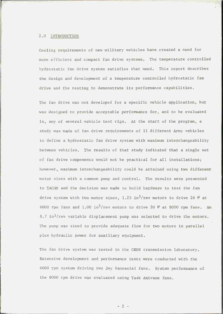
2.0 INTRODUCTION
Cooling requirements of new military vehicles have created a need for
more efficient and compact fan drive systems. The temperature controlled
hydrostatic fan drive system satisfies that need. This report describes
the design and development of a temperature controlled hydrostatic fan
drive and the testing to demonstrate its performance capabilities.
The fan drive was not developed for a specific vehicle application, but
was designed to provide acceptable performance for, and to be evaluated
in, any of several vehicle test rigs. At the start of the program, a
study was made of fan drive requirements of 11 different Army vehicles
to define a hydrostatic fan drive system with maximum interchangeability
between vehicles. The results of that study indicated that a single set
of fan drive components would not be practical for all installations;
however, maximum interchangeability could be attained using two different
motor sizes with a common pump and control. The results were presented
to TACOM and the decision was made to build hardware to test the fan
drive system with two motor sizes, 1.25 in^/rev motors to drive 26 W at
6000 rpm fans and 1.00 in3/rev motors to drive 20 IP at 8000 rpm fans. An
8.7 in^/rev variable displacement pump was selected to drive the motors.
The pump was sized to provide adequate flow for two motors in parallel
plus hydraulic power for auxiliary equipment.
The fan drive system was tested in the GEOS transmission laboratory.
Extensive development and performance tests were conducted with the
6000 rpm system driving two Joy Vaneaxial fans. System performance of
the 8000 rpm drive was evaluated using Task Axivane fans.
- 2 -

3.0 OBJECTIVES
The object of this contract was to demonstrate the concept of controlling
a dual fan hydrostatic fan drive system in proportion to the temperature
of two oil coolant lines and independently of engine speed. Both the
6000 rpm and 8000 rpm systems would turn from minimum to maximum speed
between the temperatures of 170°F and 210°F. A 100-hour system evaluation
was conducted with the 6000 rpm system and system performance of both fan
systems was assessed based on the following, points:
1. Demonstrate temperature/speed characteristics and demand cooling,
2. Determine if a flow divider is required to balance fan speed in a dual
fan system,
3. Determine if fan speed overrides are necessary,
4. Determine if system damage can occur due to fan stall,
5. Determine speed and pressure characteristics during engine speed tran-
sients at high overdrive ratios,
6. Determine system efficiency, and, in addition,
7. Investigate feasibility of utilizing a larger fan drive pump to pro-
vide auxiliary power for accessories (e.g., turret, suspension, air
compressor, bulldozer, etc.).
- 3 -

4.0 CONCLUSIONS AND RECOMMENDATIONS
4.1 Conclusions
1. The design, fabrication, and test of this temperature controlled
hydrostatic fan drive demonstrated the soundness of the concept and
the performance capabilities of a demand cooling system.
2. Flow dividers are not required to maintain speed balance when two or
more fans are driven in parallel from one pump. The torque-speed
characteristics of the fan and the resulting pressure-flow character-
istics of the fan motors act to keep the fan speeds in balance.
3. Fan speed overrides are not necessary with this fan drive control.
Fan speed is regulated by motor flow independently of fan torque and,
if fan speeds are unbalanced by some unforeseen cause, the speed of
the fastest fan is automatically controlled. Back-up protection
against overspeed is provided by the servo relief valve.
4. The servo relief valve prevents damage to the fan drive if both fans
are stalled. If only one fan is stalled, the operable fan is con-
trolled at the normal speed-temperature schedule. With normal cool-
ing of the fan drive oil, the system can be operated continuously
with one or both fans stalled, without damage to the system.
5. Acceleration tests with the drive at maximum overdrive ratio demon-
strated that the control response is fast enough to prevent excessive
pressure or fan speed overshoot.
6. The temperature controlled fan drive system will require less PTO
power than the direct drive fan for all operating conditions other
than the high temperature, high tractive effort operation. With less
- 4 -

fan drive power required, vehicle acceleration and high speed opera-
tion will be improved.
7. The fan drive pump has reserve capacity that could be used for auxil-
iary power, but, unless the pressure characteristics of the auxiliary
are compatible with the fan motor pressure, the added control complexity
and reduction in system efficiency could limit its use.
4.2 Recommendations
1. A system test should be performed in an actual vehicle application to
evaluate the performance of the fan drive system in a closed loop
cooling system.
2. A fan drive system design should be directed toward a specific vehicle
application rather than a universal application. Although some applica-
tions would probably prove to be satisfactory, the diverse cooling
requirements of the vehicle group would inevitably lead to poor system
efficiency.
3. A unique vernatherm should be developed to satisfy the exact temperature
control requirements of the fan drive system.
- 5 -

5.0 SYSTEM AND COMPONENT DESCRIPTION
5.1 System Description
A system description with brief functional information is included in this
section; a detailed description of the pump, controller, motors, and ther-
mostats follows in Section 5.2.
The temperature controlled hydrostatic fan drive system is shown schema-
tically in Figure 1 and consists of the following items:
- variable displacement pump,
- hydromechanical controller assembly,
- two fixed displacement hydraulic motors,
- two thermostat assemblies,
- two push-pull control cables,
- motor line check valves, and
- oil make-up and fan drive cooling circuit (including heat exchanger
and filter).
Figure 2 shows the actual test cell installation of the above components.
The system layout allows a great deal of packaging latitude by close coup-
ling the motor/controller and remotely mounting the thermostat assemblies
and fan motors.
The heart of the system is the variable displacement pump which supplies
a particular output flow to the fan motors according to stroking signals
from the controller assembly. It is this regulated flow which determines
the speed of the fan motors.
- 6 -

The controller communicates its pump stroking signal via a pilot valve.
This signal is the product of the mechanical action of the temperature
and speed sensor inputs upon the summing bar.
The position of the temperature input is a function of the temperature at
the remote thermostat. When the temperature at either thermostat reaches
170°F, a mechanical signal is communicated to the controller via a preci-
sion push-pull cable. This signal is proportional to temperature until
it reaches its full stroke at 210°F. In order to exercise exact control
over the controller assembly during the initial development testing, the
thermostats were not incorporated. Instead, the temperature inputs were
simulated by exact manual adjustment of a threaded piston inserted in the
controller housing in place of the thermostat cable.
The oil make-up circuit performs two functions. First, it supplies oil
from a gerotor pump to the ball piston pump pintle to "make up" for jour-
nal leakage. Secondly, it provides for fan system cooling and filtration.
Check valves have been incorporated in parallel to both fan motors to pre-
vent overpressurization in the return line during fan deceleration.
5.2 Component Description
5.2.1 Pump
The fan drive pump is basically the 8.7 in3/rev variable displacement
radial piston ball pump designed in 1966 for the XM-1 hydromechanical
transmission. The housing, pintle, and actuators were designed to con-
form to fan drive packaging criteria (e.g. PTO flange mounting and inte-
gral sump) and to be adaptable to a reversed direction of input shaft
- 7 -

rotation. The major elements of the pump are a rotating cylinder block,
a stationary porting pintle, a strokable race, stroke actuating pistons,
an integral make-up pump, and a relief valve.
The cylinder block is a seven-cylinder radial ball piston design which
rotates on a nodular iron pintle journal.
The race is anchored at the pintle pin and pivots on a spherical bushing
pressed into an ear on the race. Opposite the spherical bushing is a tang
on which actuator forces are applied to hold or stroke the race. Stroking
of the race is governed by the controller's hydraulic signal to the large
diameter actuator servo piston. The opposing actuator piston receives a
hydraulic signal from the pintle high pressure port. The stroke actuator
piston in this system is shimmed to produce a modest initial pump stroke.
This provides the fan system idle speed.
A gerotor make-up pump circulates oil through the fan drive cooler and
filter and back to the low pressure pump pintle port. Oil required to
compensate for ball piston and journal leakage enters the pintle; the
remainder is passed to sump through the relief valve at the pintle port.
The relief valve limits intake pressure to 50 psig.
The pump assembly is adaptable to reversed input rotation by orientation
in assembly of the make-up pump porting plate and the actuator housing.
5.2.2 Controller
The purpose of the controller is to regulate fan speed and limit pump out-
put pressure by communicating a stroke signal to the pump servo actuator
piston in response to temperature input signals, individual fan speeds,
- 8 -

and pump output pressure. The temperature input signals are mechanical
inputs from remote thermal power elements. Fan speed is communicated by
sensing the flow across an orifice in both fan return lines.
The controller is mounted directly to the pump pintle and consists of an
aluminum housing with a single valve servo relief circuit and a two-valve
speed sensing circuit.
The servo relief circuit is normally closed at the servo relief valve
until pump pressure reaches a predetermined value (approximately 10%
above system pressure at maximum fan speed). At this pressure, the valve
spring force is overcome and the relief valve feeds the pump destroking
piston causing pump output to decrease. The purpose of this circuit is
to prevent overpressurization in the event of fan stall or line blockage
and to prevent a gross overspeed of the fans (servo pressure is also a
function of fan speed).
The speed control circuit is responsible for controlling fan speed in
proportion to temperature input independently of engine speed. This is
accomplished by a summing bar and pilot valve used in conjunction with a
speed reference valve, thermostat input signals, and a light return spring
as shown in Figure 3.
The pilot valve communicates a hydraulic signal to the pump servo actua-
tor piston in response to the mechanical action of the speed reference
valve and temperature inputs on the summing bar.
The speed reference valve moves vertically upward in proportion to flow
across the fan return line orifice by balancing, with a spring, the
- 9 -

upstream and downstream orifice pressures at the ends of the valve. A
shuttle ball check valve is used between the upstream lines to select the
highest flow to be controlled. This flow differential between both fan
lines is insignificant during normal operation.
The temperature inputs act vertically downward on the summing bar in
proportion to the temperature at the thermostat housings.
For each position of the summing bar due to temperature input, there is
a corresponding geometric equilibrium position of the speed sensor valve
which allows the pilot valve to achieve a balanced (null) position. An
independent change of temperature or speed input moves the linkage bringing
the pilot valve out of its null position. The resultant pilot valve signal
to the pump servo actuator piston adjusts the pump flow to the new input
and restores equilibrium. Thus, the system maintains a constant fan speed
for a specific temperature input and is unaffected by pump speed.
5.2.3 Motor - Picture or Sketch.
The hydraulic motors are positive displacement radial ball piston motors whos
major components are front and rear housings, a twin port pintle, a rotating
cylinder block, 5/8 diameter precision steel balls, an elliptical race, and a
splined output shaft. (See figure 4) Two variations of this motor were buil
for the fan drive system. One was a 1.0 in^/rev motor with a seven-cylinder
block; the other was a 1.25 in /rev motor with a nine-cylinder block.
Oil supplied under pressure from the pump is fed to one of the pintle
ports, forcing the balls outward against an elliptical race. Part of
this outward force is vectorially resolved into a specific torque causing
- 10 -

the cylinder block and output shaft to turn. The oil charged cylinder
then surrenders its oil through the adjacent pintle exhaust port by the
inward movement of the ball as it runs in the race.
Orientation of the elliptical race in assembly gives the capability of
reversing the direction of motor rotation.
5.2.4 Thermostat Assembly
The thermostat assembly shown in Figure 5 has the function of communicat-
ing a mechanical signal to the controller to indicate the temperature of
the object cooling system.
The thermostat housing is mounted in a cooling line with the sensor end
of a thermal power element protruding slightly into the oil flow path.
This power element, when coupled to a specific spring reaction force and
rate, will produce a mechanical movement in proportion to temperature over
a specific range. The Vernatherm in this system activates at 170°F and
provides a signal up to 210°F. Its total mean piston travel is .450".
- 11 -

6.0 RESULTS AND DISCUSSION
6.1 Temperature/Speed Characteristics
With the temperature input to the summing bar accomplished manually, a
steady-state performance matrix was constructed by plotting fan speed at
various increments of controller input and pump speed. System response
during the test was smooth, accurate, and repeatable. The matrix for the
6000 rpra fan system is shown in Figure 6. A graph of fan speed versus
temperature input at constant pump speed is shown in Figure 7.
An analysis of Figure 7 shows that the fan control system is essentially
a dual stage system. The first stage is the fan idle mode which allows
the fans to turn at low speed when cooling is not required. The fan idle
speed, being a function of initial pump stroke, changes slightly in pro-
portion to pump speed. With pump speeds of 900 to 3200 rpm, the idle
speed varied from 105 to 340 rpm.
The second fan control stage begins when the thermostat input (or manual
actuation) begins to move the controller summing bar. At this point the
fan speed rises quickly and smoothly to approximately 2100 rpm. (The
thermostat input to signal this transition should be designed such that
it occurs at 170°F.) Any further incremental input to the summing bar
results in a corresponding change in fan speed. An input of .325 inch
will increase fan speed from 2100 rpm to 6000 rpm.
The horizontal nature of the isothermal fan speed lines demonstrates the
system independence of pump speed.
- 12 -

The maximum overdrive ratio line establishes the boundary beyond which
the pump is unable to supply sufficient output to maintain a high fan
motor speed. The position of this line in the matrix in no way hinders
the cooling capability of the system because the highest cooling require-
ments generally occur at relatively high engine speeds. Full cooling
capability is available at approximately 2100 rpm PTO speed.
A temperature/speed matrix was also plotted for the 8000 rpm fan system
and is shown in Figure 8. With this system the idle speed varies from
110 to 360 rpm over the range of pump speed. The threshold fan speed is
3100 rpm and .325 inch of summing bar stroke is required to increase the
fan speed to 8000 rpm.
6.2 Fan Speed Balance
For both the 6000 rpm and 8000 rpm dual fan systems, a series of tests
was run to determine if one fan speed would differ significantly from the
other. The results of that testing are shown in Figure 9. In summary,
even though high hydraulic line length ratios were used between the indi-
vidual fans, the difference in fan speed was judged to be insufficient to
warrant the use of flow divider devices.
The relatively equal fan speed performance is due to the fan's torque/
speed relationship. Fan speed varies with the square root of input
torque. Therefore, for any fan motor torque reduction due to increased
Line loss, the effect on fan speed will be attenuated by this square rela-
tionship. The uniformity of reaction of both fans to dynamic input is
demonstrated in Figure 10.
- 13 -

6.3 Fan Qverspeed
Analysis of the fan drive system shows that fan overspeed is not a pro-
blem and additional speed override devices are not required. Within the
controller, the speed of the fastest fan is automatically controlled and
the servo relief valve setting places an absolute ceiling on fan speed.
For such a fan system, fan overspeed was thought most likely to occur as
a result of excessive temperature input to the controller, high pump
acceleration rates at maximum pump stroke, or the stalling of one fan.
Extensive testing indicates that none of these areas present a serious
problem.
Sensitivity to increased pump stroke is shown by the position of the
dashed line on Figures 6 and 8. For both fan systems, maximum fan speed
(6000 or 8000 rpm) is attainable with .325 inch temperature input.
Speeds of 6600 and 8800 rpm are possible with .050 inch additional tra-
vel. (NOTE: The capability of the system to allow 10% overspeed was an
initial system objective.) Although higher speeds were not plotted, the
system will control to higher fan speed. For this reason, the actuating
thermal elements must be carefully matched to the system or a stroke
limiter should be incorporated into the thermostat assembly.
Figure 10 shows that under high pump acceleration the fan overspeed is
slight (285 rpm) and of brief duration.
Figure 11 shows that the stalling of one fan does have a slight effect on
the performance of the other at high speed. An overspeed of 300 rpm was
recorded at .325" adjustment.
- 14 -

6.4 Fan Stall
The system is designed so that it cannot be damaged by fan stall. The
servo relief valve protects against the stalling of both fans by destrok-
ing the pump. The stalling of one fan results in the other fan being con-
trolled by the normal controller speed/temperature schedule.
Testing to confirm the operation of the servo relief valve was clouded by
the poor condition of the valve and sleeve after an early incidence of
system contamination. Throughout the test the valve would become stuck
fast in the sleeve bore.
With one fan blocked, a performance matrix was run with the other fan and
is shown in Figure 11. Note that the maximum overdrive ratio has been
shifted significantly. This occurs because the pump output to the one
remaining fan motor doubles and high fan speeds are attainable at lower
pump speeds. The speed/temperature schedule was essentially unchanged
from the dual fan system. At the maximum temperature input stroke (.325")
the observed maximum fan speed was 6300 rpm. With both fans operating
the maximum speed was 6000 rpm.
6.5 Effect of Pump Acceleration
Figure 10 exhibits the reaction of fan speed to rapid acceleration of the
pump. This graph shows that both fan speeds behave uniformly and that
they are held in a fairly narrow band even though the pump speed is accel-
erating quickly through a wide range of speeds. With an eye toward possi-
ble fan overspeed, it can be seen that with extremely high pump accelera-
tions the maximum fan speed overshoots only 285 rpm (6075 rpm steady-
state, 6360 rpm transient).
- 15 -

6.6 Efficiency
The temperature controlled hydrostatic fan drive system allows greater
overall system efficiency by allowing the fans to idle at speeds from 100
to 360 rpm v/hen cooling is not required (below 170°F engine and transmis-
sion oil temperature). At these fan speeds the pump horsepower require-
ment varies from approximately 2 fP to 10 H5 depending on pump speed. The
fan idle speed characteristics are shown in Figure 12.
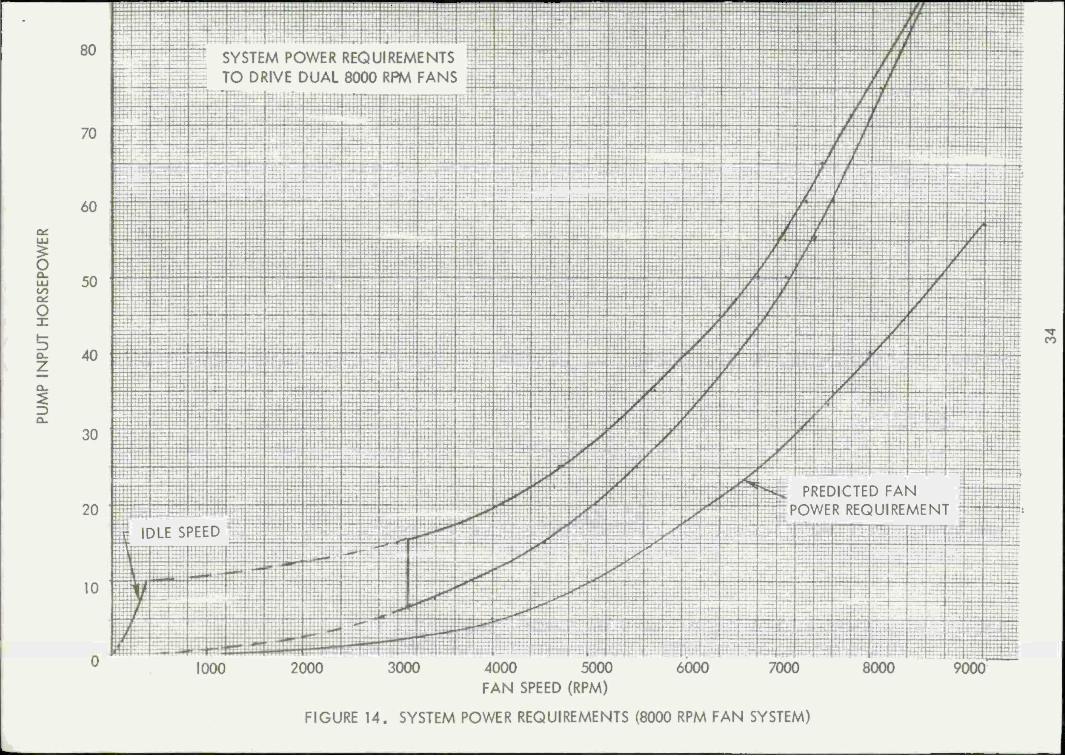
The power requirements for the full range of fan speeds are shown in
Figures 13 and 14. These curves are presented as bands because of the
pump input power to pump speed relationship (by the nature of the system,
any given fan speed can occur over a wide range of pump speeds and pump
input power will increase with pump speed).
The cubic relationship of fan speed and power is illustrated by both
figures. For reference purposes, an idealized fan power curve is also
shown in both figures.
Values may be compare! between the actual curves and the ideal curve to
gain a feel for the pump to fan efficiency. It must be remembered, how-
ever, that the reference curve is merely a mathematical idealization and
is not an actual fan performance curve. Two legitimate points on these
curves, however, are the rated speeds of 6000 and 8000 rpm. Based on
these points, the pump/fan efficiency is 69% (at 6000 rpm) for the 6000
rpm fan and 53.3% (at 8000 rpm) for the 8000 rpm fan system. The lower
efficiency of the 8000 rpm fan is a product of the sensiLivity of the wet
case motors to high speeds and the large pump/motor size ratio.
- 16 -

6.7 System Performance
Reference to the thermostat assembly output curve of Figure 15 indicates
the need for engineering a thermal power element specifically to the
requirements of the fan drive system. The thermal power element used
provided a continuous output signal from 170 F to 210°F as required; how-
ever, its output travel from this range was .450 inch and additional tra-
vel to over .500 inch at 235°F was noted. The initial design assumptions
for the controller provided for only .375 inch thermostat output with
this .375 inch travel allowing a 10% fan overspeed capability (6600 rpm
and 8800 rpm). To achieve the rated fan speeds of 6000 and 8000 rpm, an
input of .325 inch was required.
Without controller geometry changes, the increased travel of the thermo-
stat signal was inconsistent with the desired fan speed range.
To evaluate the performance of the thermostats in the system, a stroke
limiter was incorporated in the thermostat housing to eliminate any tra-
vel beyond .450 inch (at 210°F) and sufficient clearance was left at the
thermostat/summing bar interface to result in .325 inch travel. This
resulted in system activation at 185°F and the performance curve is shown
in Figure 16.
- 17 -

7.0 TEST PROCEDURE
All testing was performed in the spin stand facility with power supplied
by a 6V53 Detroit Diesel engine. Instrumentation was provided to monitor
pump parameters (input rpm, torque, make-up pressure, output pressure,
and sump temperature), motor parameters (rpm, inlet pressure, and outlet
pressure), and thermostat temperature. The testing procedure follows.
7.1 Green Run
The fans were run at 4000 rpm with pump speeds of 550, 1000, 1250, and
1500 rpm for 30 minutes at each speed. Teardown and component inspection
followed immediately.
7.2 Controller Calibration
The fan return line orifices and the speed sensor valve spring force were
adjusted to conform to the required speed envelope. After observing the
system pressure obtained while running at 6600 rpm (maximum) fan speed,
the servo relief valve was set on a flow bench at 10% above that pressure,
7.3 Performance Evaluation
To demonstrate the system temperature/speed characteristics, both a
steady-state performance matrix and a dynamic response test were run with
the system.
To construct a steady state matrix, fan speed was observed for discrete
increments of pump input speed and temperature input signal over their
entire ranges. The relationship of summing bar travel and fan speed was
observed to aid in the later installation of the thermostat assembly.
- 18 -

The dynamic response test was performed by recording on strip charts the
reaction of fan speed to rapid variations of pump input speed.
7.4 Fan Speed Differentials
A complete performance sequence was run to determine if the speed of one
fan would vary significantly from the other. Testing was performed with
both equal and unequal hydraulic line lengths.
7.5 Stall Evaluation
This test was run by communicating simulated fan stall conditions to the
controller and observing the system function. The effect of both fans
being stalled was evaluated by confirming the operation of the servo
relief valve with the flow to both fans blocked. The effect of a single
fan being stalled was evaluated by blocking flow to one fan and running
a complete performance evaluation of the other.
7.6 Efficiency
Efficiency data for both the 6000 and 8000 rpm fan systems were taken for
each point in their performance matrices. Since the instrumentation sys-
tem did not allow direct reading of fan torque, the system efficiency was
expressed indirectly as the horsepower requirements to drive the fans
through their entire speed range.
7.7 System Evaluation with Thermostats Installed
Prior to this section of the test, the temperature input to the control-
ler was simulated by manual actuation. This final system evaluation
would involve system control by the actual thermostat assemblies. To
accomplish this, the output characteristics of each thermostat assembly
- 19 -

were first determined by plotting the mechanical output as a function of
temperature. Knowing this and the required summing bar movement to obtain
the full range of fan speed, the thermostat assemblies were incorporated
into the system and the system performance parameters (thermostat tempera-
ture, fan speeds, and engine speed) were plotted on a strip chart recorder,
- 20 -

o FAM MOTOR
ro
X TAN DRIVE COOLER
REUEF VALVE-SOPSIG
FILTER -"K>/K
^T?JO INPUT
MOKE-UP PUMP .09 IN^REV
FIGURE 1 . FAN DRIVE SCHEMATIC

22

PILOT VALVE OUTPUT
DISC ORIFICE-
FAN RETURN LIME
o -J U.
1 ^
PILOT VALVE FEED PINTLE HIGH PRESSURE
PILOT VALVE SPOOL
k^O
THERMOSTAT CA8LE
LOW SPEED ADJUST
CONTROLLER HOUSING*
BALANCE SPRING
FIGURE 3. FAN SPEED SENSING AND CONTROL CIRCUIT

ho
FIGURE 4. MOTOR ASSEMBLY AND COMPONENTS
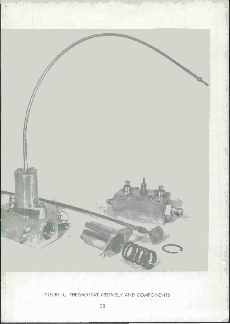
FIGURE 5. THERMOSTAT ASSEMBLY AND COMPONENTS
25

2
CX. on
z <
o 1000 2000
PUMP SPEED (RPM)
3000
FIGURE 6. PERFORMANCE MATRIX (6000 RPM FAN SYSTEM)
26

7000
i s UJ
Bi z <
6000
5000
4000
3000
2000
1000
' ^— , ■■ ■■'- -
y rjj JT
JT /
hrr
PFPFPiPMANTF Of s rfXrr ti\rvJi\/v\AMN^[; \jv jT AHH RPM FAN SYSTEM .X OUU rvi/Vi inlN j I Ji Liv\ s
AT 2600 RPM PUMP SPEED / j*
y / /
j
/ ::::: yr
/ / /
t :M. / / / / j
2 / / f
'",", .. .f-.U L
"! " .. X' i i
i • 1 l
0 .10 .20 .30
THERMOSTAT SIGNAL INPUT (INCHES)
.40
FIGURE 7. SYSTEM PERFORMANCE AT CONSTANT PUMP SPEED
27

1000 2000
PUMP SPEED (RPM) 3000
FIGURE 8. PERFORMANCE MATRIX (8000 RPM FAN SYSTEM)
2L

Fan Speed (rpm)
6000 rpm Fan System 8000 rpm Fan System
Fan Lines 129" and 69"
Length Ratio 1.86:1
Fan Lines 129" and 25"
Length Ratio 5.2:1
Fan Lines 102" and 66"
Length Ratio 1.55:1
Speed Difference
(rpm) % Difference
Speed Difference
(rpm) 7o Difference
Speed Difference
(rpm) 7o Difference
2000 10 .5 25 1.25
3000 30 1.0 45 1.5 30 1.0
4000 40 1.0 30 .75 30 .75
5000 50 1.0 75 1.50 75 1.50
6000 80 1.3 160 2.66 50 .83
7000 50 .72
8000 m _ _ _ 100 1.25
FIGURE 9 Speed Variation between Two Fans in Dual Fan System
- 29 -

CO o
'\
"\ t i
f
M
PUMP TORQUE
1
V^^
f
/tt ~:|;T i A / \ / j/
J vv_/' , -————-
FAN SPEED FAN* a
^_-^r x_ wv^^x^w-^-. ^
FAN SPEED FAN * 1
jf\ r\ ny\ r<^~\ r \j \j \y PUMP SPEED
•/
*«oo WOO
• S**oo ■ 4 800
slOO 3«>0O 30O0
^v^^^ ^"v-—^^_^
^*"~——»-^^ ^s^v.
—!— - ■ -
■ -. ihOO fcOOO
■ 5 MOO f- M800
SlOO 5600 300O
UK» »f
t 3000 -(■■■■ 2700
I moo
f l»0O 4 ISOO f noo
900 feOO 300
-I o «-a
FIGURE 10. REACTION OF FAN SPEED TO PUMP ACCELERATION

6000 RPM FAN SYSTEM MATRIX WITH ONE FAN STALLED
SINGLE FAN DUAL FAN
CO LU X U 2
5 z —I < z o CO
CO
o cm
1000 2000
PUMP SPEED (RPM)
3000
FIGURE 11 . SINGLE FAN SYSTEM PERFORMANCE WITH ONE FAN STALLED
31

LU
o Q_ LU CO OH
O X
Z) CL-
IO
1 1 1 1 1 " !
y / / / f f J J
/ / / / / / / / / /
j / / / f /
i *
/ J / J / / / / / / / / / /
j * / /
6000 RPM SYSTEM / / / / / J / /
/ j y X A
J -J£ Äfififl PPM QV^TPM / ir OUUU i\r/V\ JY JILM
/ 'Jr I" III J ? / f
/ y J y
/ J \ i s
/ A'
/ 1
_
0 100 200 300
FAN IDLE SPEED (RPM)
400
FIGURE 12. PUMP HORSEPOWER REQUIREMENTS AT FAN IDLE
32

GO CO
FIGURE 13. SYSTEM POWER REQUIREMENTS (6000 RPM FAN SYSTEM)
80
LU
O UJ oo
o x t— => Q-
z
=> a.
70 1 ■ ■
60
50
40 I
30
20
10
SYSTEM POWER REQUIREMENTS TO DRIVE DUAL 8000 RPM FANS
IDLE SPEED
I
/
JS
1 I
//
' : i '.A lliflU ; j£
/
/
■ jf
3
CO
. . —iff
>^ PREDICTED FAN
POWER REQUIREMENT
1000
:
2000 3000 4000 5000 6000 7000 8000 9000 FAN SPEED (RPM)
FIGURE 14. SYSTEM POWER REQUIREMENTS (8000 RPM FAN SYSTEM)

LU X u Z
i D CL »—
o
IS)
o 0£
,. —
^ 1 ' 50- __^: /
y y
\y *
w j __4 ■■ H
j J 1
1 J J 1 /
JU /
1
j I J j 1 1
L\J t
1 l /
/
/ i n / .10 /
/
/ i /
Jr
n ^ \ 170 180 190 200 210 220
THERMOSTAT TEMPERATURE (°F)
FIGURE 15. THERMOSTAT PERFORMANCE
230
35

I
tfiti. SP€ti
O
THEZMOSTfiT TEMP j (V)
(*P«) -***) $
MM tjj SPEED (RPM)
PUMP INPUT SPEED
r-l
FIGURE 16. SYSTEM PERFORMANCE EVALUATION

APPENDIX
FAN DRIVE SPECIFICATIONS
A - 1

COMPONENT SPECIFICATIONS
Pump Assembly
- Displacement: 0-8.7 in3/rev (seven 1.625" diameter balls)
- Pressure: 3000 psig maximum
- Speed: 4000 rpra maximum
- Direction of rotation: clockwise or counterclockwise
- Make-up pump: .89 in^/rev gerotor (14 gpm at 3600 rpm)
- Make-up relief pressure: 50 psig
- Servo relief pressure (ref): 1800 psig (adjustable)
- Mounting flange: eight 3/8 bolts on 7.00 in. diameter bolt circle
- Input spline: 16-tooth 30° P.A.; 16/32 pitch 1.00 P.D.
- Sump capacity: three quarts
- Oil: SAE 30
- Weight: 82.5 lb.
Controller
Hydromechanical, two valves with summing bar and servo relief valve.
- Temperature input: mechanical, variable
- Hydraulic input: pump pintle pressure; fan return line flow
- Output: hydraulic signal to pump actuator servo piston
- Servo relief pressure: 1800 psig (adjustable to suit fan speed
requirements)
- Weight: 9.8 lb.
Motor
- Type: fixed displacement radial ball piston double lobe
A - 2

- Displacement: 1.25 in3/rev, 9 cylinder, 5/7" ball
- Rated speed: 6000 rpm
- Rotation: clockwise or counterclockwise
- Mounting flange: four V bolts on 6.375" bolt circle
- Output spline: 13-tooth, 30°P.A.; 16/32 pitch .8125 P.D.
- Weight: 13.7 lb.
Motor (8000 rpm)
Same as above except:
- Displacement: 1.00 in3/rev, 7 cylinder, 5/8" ball
- Rated speed: 8000 rpm
Thermostat Assembly
Aluminum housing with thermal power element.
- Power element: .450" travel from 170°F to 210°F
- Reaction spring: 120 lb. initial load; 115 lb/in rate
- Control cable: push-pull precision ball bearing cable, 1.0" stroke,
4" bend radius
- Assembly weight: 7.6 lb.
Cooler
- Type: oil/air
- Heat rejection: 2257 BTU/min
- Oil outlet temperature: 208°F
- Air static drop: 5.3" H20
- Oil pressure drop: 6.3 psi
- Flow H.P. air: 3.23
A - 3

Filter
- 10 micron nominal
- 15 micron absolute
- 20 psi pressure drop at 14 gpm
Check Valve
- Opening pressure: 5 psig
- Proof pressure: 5000 psig
Hose and Fittings
- High pressure hose: 1.0 inch I.D,
- Low pressure hose: 1.0 inch I.D.
A - 4

DISTRIBUTION LIST
Number of Copies
Commander U.S. Army Tank Automotive Command Attn: AMDTA-RGT Warren, Michigan 48090
Commander U.S. Array Tank Automotive Command Attn: AMDTA-RE Warren, Michigan 48090
Commander U.S. Array Tank Automotive Command Attn: AMDTA-UL Warren, Michigan 48090
Commander 15 Defense Documentation Center Cameron Station Alexandria, Virginia 22314


ORDNANCE SYSTEMS
100 Plastics Avenue Pittsfield, Massachusetts 01201
Th>gress Is Our Most Important Product
GENERAL® ELECTRIC
RESEARCH, DESIGN AND PRODUCTION OF PRECISION ORDNANCE EQUIPMENT - SINCE 194